Page 1L152 0121A
U
L
CUS
R
Read and Save These Instructions
All Hoods Must Be Installed By A Qualied Installer
INSTALLATION INSTRUCTIONS
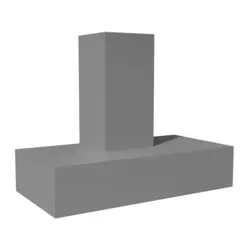
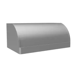
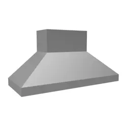
CWEH9 WALL MOUNT HOOD
Read All Instructions Thoroughly Before Beginning Installation
WARNING - TO REDUCE THE RISK OF FIRE, ELECTRIC SHOCK,
OR INJURY TO PERSONS, OBSERVE THE FOLLOWING:
A. Installation work and electrical wiring must be done by qualied person(s)
in accordance with all applicable codes and standards, including re-
rated construction. Switch power o at service panel and lock the service
disconnecting means to prevent power from being switched on accidentally
during installation.
B. When cutting or drilling into wall or ceiling, do not damage electrical wiring
and other hidden utilities.
C. Ducted fans must always be vented to the outdoors.
D. Sucient air is needed for proper combustion and exhausting of gases
through the ue (chimney) of fuel burning equipment to prevent back
drafting. Follow the heating equipment manufacturer’s guideline and
safety standards such as those published by the National Fire Protection
Association (NFPA), and the American Society for Heating, Refrigeration
and Air Conditioning Engineers (ASHRAE), and local code authorities.
E. ASHRAE residential ventilation standard 62.2 limits exhaust fans (total) to
a maximum of 15 CFM per 100 square feet of occupiable space, unless a
back drafting test is performed or make-up air is provided. Consult a local
HVAC engineer for make-up air evaluation.
WARNING - TO REDUCE THE RISK OF FIRE, USE ONLY METAL
DUCTWORK
Page 2L152 0121A
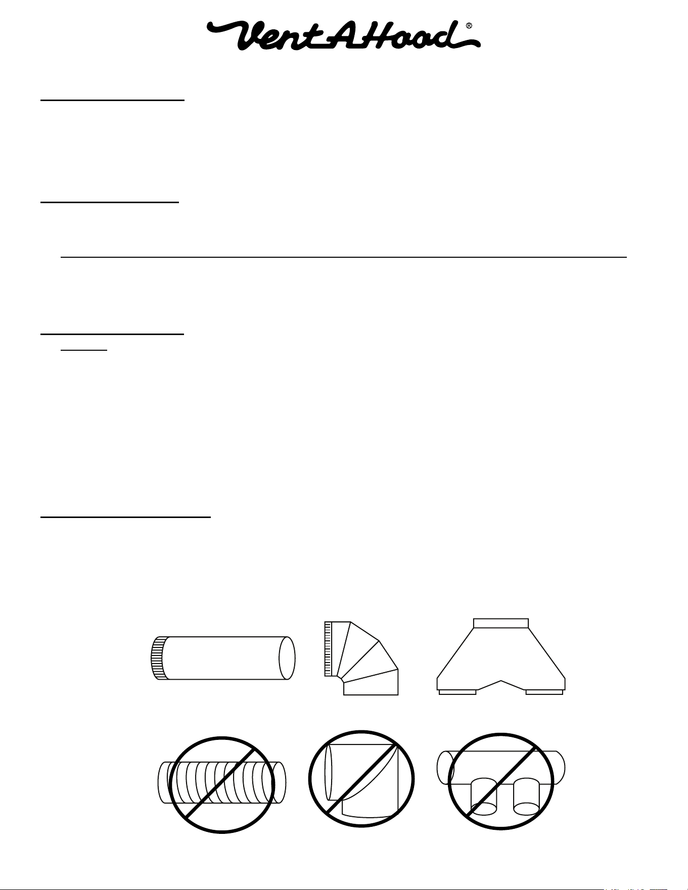
Ducting Do’s and Don’ts
YES
NO
Smooth Duct
Smooth Gradual Turn
Proper Combining
of Two Ducts
Flexible Duct
Sharp Angled Turns
Improper Combining
of Two Ducts
General Requirements
• Observe local codes regarding special duct requirements and placement of duct against combustibles.
• UsingVent-A-Hoodtransitions(backpage)willensurepropereciency.
• UsingVent-A-Hoodroofjacksorwalllouvers(backpage)willensurepropereciency.
• Where possible, seal joints with HVAC foil tape.
• The hood must be ducted to the outdoors without restrictions.
Blower Requirements
• The single blower unit (B100) requires 6” round duct or equivalent (28 square inches), and the dual
blower unit (B200) requires 8” round duct or equivalent (50 square inches).
Blower Combined Duct Dize Sq. Inch Area Vent-A-Hood Transition
Single (B100) 6" round or equivalent 28 sq. in. N/A
Dual (B200) 8" round or equivalent 50 sq. in. N/A
Single and Dual (B100 & B200) 10" round or equivalent 79 sq. in. N/A
Two Duals (Two B200s) 12" round or equivalent 113 sq. in. N/A
Ducting Requirements
• NEVER reduce the duct size.
• Whencombiningductstogether,thesquareinchareamustreectthetotalsquareinchareaofthe
ducts being combined.
• Donotuseexibleorcorrugatedduct.Thistypeofductwillrestrictairowandreduceperformance.
• Onlyusesmooth,galvanized,metalduct.
• Make the duct run as short and as straight as possible with as few turns as possible.
• Avoid sharp-angled turns. Instead, use smooth, gradual turns such as adjustable elbows or 45 degree
angled turns.
• Forductrunsover20feet,increasetheductdiameterbyoneinchforeverytenfeetofduct.
• A 90 degree elbow is equal to 5 feet of duct.
Termination Requirements
• Airowmustnotberestrictedattheendoftheductrun.
• A wall louver or roof jack is required for each duct run.
• Everywalllouverorroofjackmustincludeagravitydampertopreventbackdrafts.
• Do not use screen wire or spring-loaded doors on wall louvers or roof jacks.
• Donotterminateventingintoanatticorchimney.
Page 3L152 0121A
8" Round
Motor
Cooling
Vent
Electrical
8" Round 6" Round
Motor
Cooling
Vent
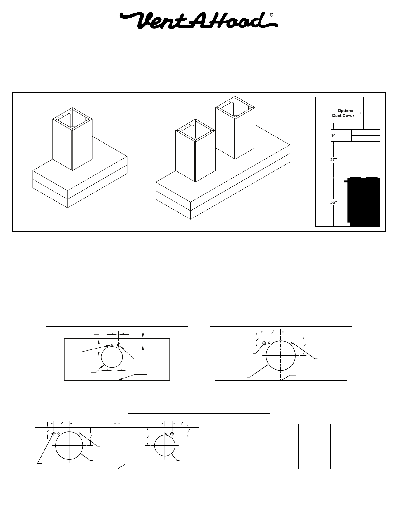
Model Width A Width B
CWEH9-342 8" 6.5"
CWEH9-348 10" 8.5"
CWEH9-354 11" 9.5"
CWEH9-360 12" 10.5"
Centerline
of Hood
Vent
Hole
6” Outlet
1 ½”
Electrical
Wall Side
1 ¾”
½”5 ¼”
Installation Details
1) Read all instructions thoroughly before beginning installation. Note: These instructions apply to standard hoods only.
Custom hoods may require additional specication consideration.
2) When installing a CWEH9 wall mount hood, it is recommended that the bottom edge of the hood be located no more
than 27” above the cooking surface for optimum performance.
3) IF THE HOOD IS TO BE “BACK VENTED”, PROCEED DIRECTLY TO STEP 4.
Install the duct(s) from the outside of the home down to the location of the exhaust outlet(s) on the top of the hood
plus 1”. This will allow the duct to engage 1” inside of the exhaust outlet. Consult the connection diagrams (below and
on next page) for further details on exhaust outlet placement.
Use HVAC foil tape to seal all joints. A complete listing of available Vent-A-Hood ducting materials is provided on the
back page of this instruction sheet.
4) Remove the hood from its packaging and place the hood, wall side down, on the oor or countertop in front of the wall
where it will hang.
Shown with duct cover(s) installed (sold separately).
Connection Diagram (30”- 48” Widths)
Connection Diagram (42”- 60” Widths)
900 CFM B200 Dual & B100 Single Blower
(Top View)
300 CFM B100 Single Blower
(Top View)
600 CFM B200 Dual Blower
(Top View)
Connection Diagram (30”- 54” Widths)
Outlet Spacing for
900 CFM Models
Page 4L152 0121A
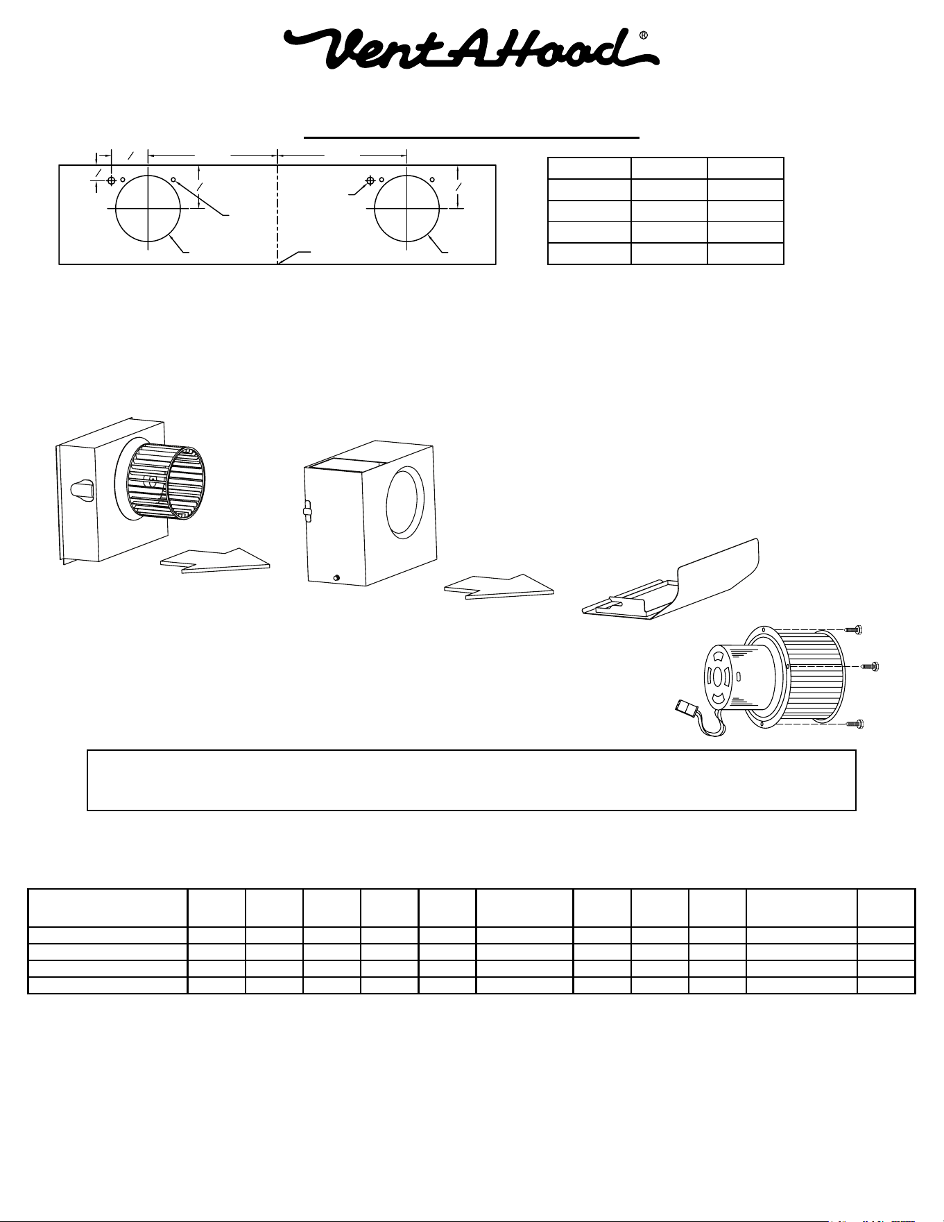
8" Round
8" Round
Motor
Cooling
Vent
Electrical (2)
Model Width A Width B
CWEH9-448 11" 11"
CWEH9-454 11" 11"
CWEH9-460 12" 12"
CWEH9-466 13" 13"
Installation Details Continued
5) Remove the shipping tape that is securing the E-Z Clean shield(s) inside the hood. Remove the E-Z Clean shield(s) by
lightly pulling it toward the front of the hood. Gently close the back draft damper(s) from the top side of the hood. To
remove the blower housing(s), unsnap the suitcase latches (one on each side of the housing). The housing(s) should
be pulled forward and gently “tipped” to clear the blower wheel(s) and then out of the hood.
6) Remove the three screws retaining the blower motor(s). Unplug
and remove the motor(s), taking care not to damage the blower
wheel(s). It is not necessary to remove the blower wheel from
the motor.
Connection Diagram (48”- 66” Widths)
1200 CFM Double B200 Dual Blowers
(Top View)
Outlet Spacing for
1200 CFM Models
7) Install an appropriate 1/2” UL listed electrical wire clamp through each motor box electrical opening on top of the
hood. Install electrical wiring from the service panel to the hood location for each motor box. Consult the connection
diagrams (on previous page and above) for further details on electrical placement.
Model Volts Amps Hz RPM
CFM
Equivalent CFM
•
CFM
CFM
CFM
Minimum Round
Duct Size
Sones
#
B100 Single 115 2.5 60 1550 300 450 273 245 225 6" (28 in.
2
) 5.4
B200 Dual 115 4.0 60 1550 600 900 531 480 430 8" (50 in.
2
) 6.5
B200 Dual & B100 Single 115 6.0 60 1550 900 1350 804 725 655 10" (79 in.
2
) 6.3
Two B200 Duals 115 7.5 60 1550 1200 1800 1062 960 860 12" (113 in.
2
) 6.6
• BecausetheMagicLung
®
blowerusescentrifugalltrationratherthanconventionalbafeormeshlters,theMagicLung
®
blowercanhandlecookingequipmentwithhighercubicfeetperminute(CFM)requirementsandcandeliverequivalentCFMmuchmore
efcientlythanotherltrationsystems.WhencomparingtheMagicLung
®
withotherblowerunitsmadebyothermanufacturers,usethe“EquivalentCFM”.
#
RatingsinaccordancewiththeStandardTestCodebytheEnergySystemsLaboratoryoftheTexasEngineeringExperimentStation.
Warning: Make sure power is o and locked at the service disconnecting
means on the service panel during installation.

Page 5L152 0121A
Installation Details Continued
8) Remove the duct cover from its packaging. Remove the duct cover front panel. The panel is held in place with four
snaps at the corners and at least one snap on the left and right. Begin by pulling the panel away at one corner. Work
around the duct cover disengaging one snap at a time until all the snaps are loose. Beware sharp corners and edges.
Use caution to prevent bending, scratching, or dropping the panel. Remove the duct cover mounting screws from the
bottom of the duct cover. Place the duct cover, wall side down, on the top of the hood and secure it to the hood using
the mounting screws previously removed. Note: There may only be two attaching screws for smaller width duct covers.
Repeat this process if you have a second duct cover. Lift the hood and duct cover assembly to the location on the wall
where it will be installed and lightly mark the wall with a short, horizontal mark along the bottom edge of the hood.
9) Remove the hood and duct cover assembly from the wall. On the back side of the hood, measure the distance between
the bottom edge of the hood and the top edge of the wood mounting strip. Measure this distance above the horizontal
line made in Step 8 and lightly mark the wall with a level, horizontal line. Measure where the center (left to right) of the
hood will be and mark the upper horizontal line on the wall with a short vertical centerline.
10) Remove the screws inside the top of the back of the hood that retain the wood strip that is recessed in the mounting
channel. Note: Some retaining screws may be located behind the blower(s). Remove the wood mounting strip from
the back of the hood and place the top edge of the strip on the upper, level horizontal line on the wall. Referencing the
vertical centerline from Step 9, place the mounting strip so it is centered (left to right) on the wall in the space where
the hood will be located. Drill pilot holes in the strip to prevent splitting. Using proper hardware, attach the mounting
strip to at least two wall studs.
11) FOR BACK VENTING APPLICATIONS ONLY. IF NOT BACK VENTING, PROCEED DIRECTLY TO STEP 12.
Note: Wall studs may interfere with back venting installations. Additional framing may be required. It is necessary to
cut duct access hole(s) in the wall prior to installing the hood.
To accomplish this, hold the hood and duct cover assembly on the mounting strip by aligning the channel at the top
of the back of the hood over the wood mounting strip on the wall. Place the appropriate elbow(s) on top of the hood in
line with the hood exhaust collar(s). On the wall, trace around the elbow(s). Remove the hood and elbow(s) from the
wall. Cut around the outside of the traced line(s), avoiding wall studs. Install the duct from the outside of the home to
the opening in the wall. Use HVAC foil tape to seal joints.
12) Hang the hood on the mounting strip by aligning the channel at the top of the back of the hood over the wood mounting
strip on the wall. While holding the hood in place, mark locations on the mounting strip through the mounting holes
in the channel at the top of the hood. Some mounting holes may be located behind the blower(s). Remove the hood
and drill 3/32” pilot holes at the center of the marks in the wood strip to prevent splitting.
13) FOR BACK VENTING APPLICATIONS ONLY. IF NOT BACK VENTING, PROCEED DIRECTLY TO STEP 14.
Place the appropriate elbow(s) on the top of the hood. Elbow(s) should be placed with the non-crimped end(s) on the
inside the collar(s) of the exhaust outlet(s). Use HVAC foil tape to seal joints.
14) Lift the hood and duct cover assembly up to the wall and hang the hood on the mounting strip, taking care to properly
align the duct connection(s) between the hood and the duct in the ceiling or wall. Secure the hood and duct cover
assembly to the mounting strip by installing the screws (previously removed from the strip in Step 10) into the pilot
holes drilled in Step 12.
Insert the electrical wire from the service panel into the electrical wire clamp on each motor box. Tighten the wire
clamp(s).
15) Replace the duct cover front panel(s) by aligning the snaps and pressing each snap into position.
16) From inside the hood, using UL listed wire nuts, attach the “neutral” wire(s) to the white lead(s), the “hot” wire(s) to
the black lead(s), and the ground wire(s) to the green lead(s) inside the motor box(es).
Warning: Do not operate hood without proper ground connection.

Page 6L152 0121A
Installation Details Continued
17) Plug the motor(s) into the hood and reinstall the blower motor(s) using the three retaining screws that were previously
removed in Step 6.
18) Replace the blower housing(s) and the blower shield(s). Make sure that the damper(s) open and close smoothly.
19) Refer to the Owner Maintenance Guide Operating Instructions for proper hood operation. Unlock and connect power
at the service panel. Test all blower and light functions to ensure they are operating properly.
Page 7L152 0121A
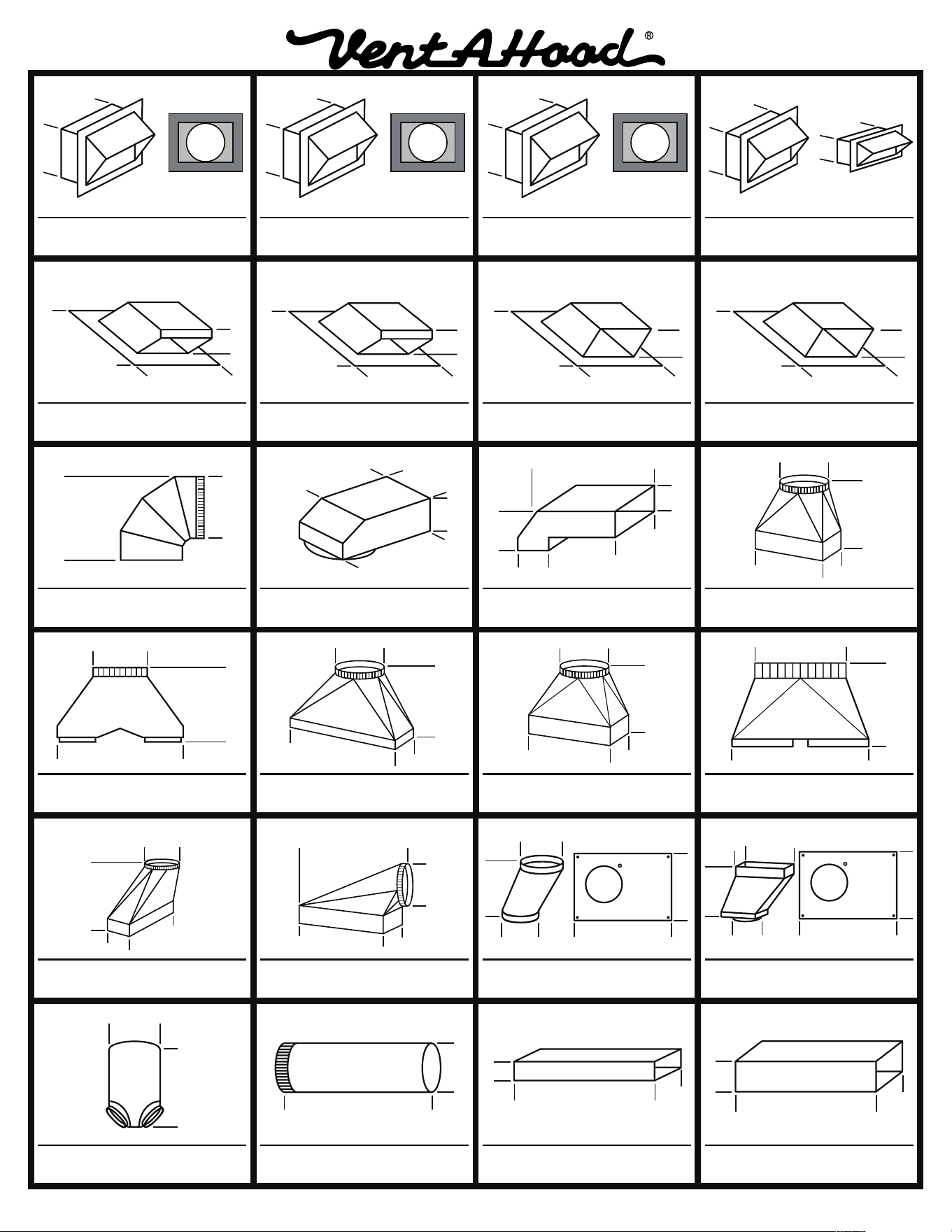
VENTING ACCESSORIES
6” RECTANGULAR DUCT PIPE
MODEL DIM
VP507 6” x 8 ½”
24”
8 ½”
6”
ROUND DUCT PIPE
MODEL DIM
VP500
VP501
VP502
6” Round
7” Round
8” Round
36”
6”
7”
8”
3 ¼” RECTANGULAR DUCT PIPE
MODEL DIM
VP504
VP505
VP506
3 ¼” x 10”
3 ¼” x 12”
3 ¼” x 16”
30”
10”
12”
16”
3 ¼”
OFFSET L & R TRANSITION
FOR ISLAND BLOWERS
MODEL DIM
VP542
VP543
Top Left
Top Right
8”
12”
5”
16”
SIDE VENT TRANSITION L & R
FOR ISLAND BLOWERS
MODEL DIM
VP544
VP545
Left Side
Right Side
19”
8”
16”
5”
OFFSET KIT - RECTANGULAR
MODEL DIM
VP550 6” Rnd to 3 ¼” x 10”
16”
11”
6”
11”
3 ¼”
10”
STANDARD ISLAND TRANSITION
MODEL DIM
VP565 5” x 16” to 8”
8”
9”
16”
5”
CLUSTER BLOWER TRANSITION
MODEL DIM
VP564 8” & 8” to 12”
18 ½”
12”
11 ¼”
“Y” TRANSITION
MODEL DIM
VP517
VP518
VP551
8” & 8” to 12”
6” & 8” to 12”
6” & 8” to 10”
18”
10”
12”
3 ¼” x 10” BACK VENT ELBOW
MODEL DIM
VP559 3 ¼” x 10”
4 ¼”
10”
14”
3 ¼”
3 ¼”
MULTI-BLOWER TRANSITION
MODEL DIM
VP562
VP563
6” & 8” to 10”
8” & 8” to 12”
VP562 - 17 ½”
VP563 - 16 ½”
10”
12”
VP562 - 23 ¼”
VP563 - 30 ½”
3 ¼” x 10” TO 7” TRANSITION
MODEL DIM
VP521 3 ¼” x 10” to 7”
7”
7 ½”
3 ¼”
10”
LOW PROFILE ROOF JACK
(MAXIMUM 4/12 PITCH)
MODEL DIM
6 ½”
VP539
VP540
VP541
6” Round
7” Round
8” Round
16 ¾”
16 ¾”
LOW PROFILE ROOF JACK
(MAXIMUM 4/12 PITCH)
MODEL DIM
10 ½”
VP552
VP553
10” Round
12” Round
22 ½”
20 ¾”
ADJUSTABLE ELBOW
MODEL DIM
VP513
VP514
VP515
6” Round
7” Round
8” Round
6”
7”
8”
VP513 - 8 ½”
VP514 - 9 9⁄16”
VP515 - 10 5⁄8”
BACK/SIDE VENT ELBOW
MODEL DIM
VP561 8” to 6” x 8 ½”
12”
6”
16”
8” Round
8 ½”
WALL LOUVER
MODEL DIM
6”
7”
8”
8 5⁄8”
VP526
VP527
VP528
6” Round
7” Round
8” Round
Back
View
1 ½” Flange
WALL LOUVER
MODEL DIM
11”
11”
VP554 10” Round
Back
View
1 ½” Flange
WALL LOUVER
MODEL DIM
13”
13”
VP555 12” Round
Back
View
1 ½” Flange
RECTANGULAR WALL LOUVER
MODEL DIM
3 ¼”
10”
VP538
VP560
6” x 8 ½“
3 ¼” x 10”
8 ½”
6”
1 ½” FLANGE
2” FLANGE
OFFSET KIT - ROUND
MODEL DIM
VP529 6” Rnd to 7” Rnd
16”
11”
6”
7”
10 ½”
LOW PROFILE ROOF JACK
(MINIMUM 4/12 PITCH)
MODEL DIM
10 ½”
VP552-HP
VP553-HP
10” Round
12” Round
22 ½”
20 ¾”
M1200 STANDARD TRANSITION
MODEL DIM
VP566 21” x 8” to 10”
10”
9”
8”
21”
LOW PROFILE ROOF JACK
(MINIMUM 4/12 PITCH)
MODEL DIM
6 ½”
VP539-HP
VP540-HP
VP541-HP
6” Round
7” Round
8” Round
16 ¾”
16 ¾”