PLANNING GUIDE
MODULAR COOKTOPS
CI152DTT | CI244DTT | CI304DTT | CI365DTT | CI122D | CI152D | CIT122D |
CIT152D | CG151D | CD5D
© FISHER & PAYKEL LIMITED 2025 PAGE 290003312C PLANNING GUIDE MoDULAR CooKToPS VERSIoN C - MAY 2025
The models shown in this Planning Guide may not be available in all markets and are subject to change at any time. Product specifications may vary from those shown. This Planning Guide should not be used as installation guidance for any product. Further information is required to safely and correctly install the
products featured here. Specific installation guidance will be available with the product on delivery and on our website fisherpaykel.com
CI152DTT | CI244DTT | CI304DTT | CI365DTT | CI122D | CI152D | CIT122D | CIT152D | CG151D | CD5DPLANNING GUIDE | MODULAR COOKTOPS
This comprehensive planning guide provides you with the framework and tools to achieve your desired design outcome with Fisher & Paykel appliances. In this guide, you will
find a range of conceptual, detailed, and dimensional product information to bring your ideas to life and create spaces that truly reflect your vision.
CONCEPT DESIGN PAGE DEVELOPED AND DETAILED DESIGN PAGE DEVELOPED AND DETAILED DESIGN PAGE
Specification Guide 3
System Overview 4
Primary Modules 5
Auxiliary Modules 6
Data Sheets 8
Primary Induction Cooktop, 15" 9
Primary Induction Cooktop, 24" 10
Primary Induction Cooktop, 30" 11
Primary Induction Cooktop, 36" 12
Auxiliary Induction Cooktop, 12" 13
Auxiliary Teppanyaki Cooktop, 12" 14
Auxiliary Induction Cooktop, 15" 15
Auxiliary Teppanyaki Cooktop, 15" 16
Gas on Glass Modular Cooktop, 15" 17
Auxiliary Ventilation, 5" 18
Recirculation Kit 22
Product Decisions 24
Modular System Capabilities 25
Modular System Options 26
Pairing Guide 27
Modular Ventilation Capabilities 28
Planning Considerations 29
Installation Overview 30
Combined Installation 31
Typical Configurations with Modular Ventilation 32
Typical Configurations with Overhead Ventilation 33
Countertop Details 34
Clamping Locations 35
Cooktop Ventilation 36
Installation with Built in Ovens 37
Modular Ventilation 38
Common Ducting Scenarios 39
Duct Length Recommendations 40
Blowerbox Cabinetry 41
Electrical Services 42
Modular Connections 44
CONTENTS
IMPORTANT NOTE
DO NOT install the cooktop directly above a dishwasher, fridge,
freezer, washing machine or clothes dryer, as the humidity may
damage the cooktop electronics.
<< CONTENTS
i
i

© FISHER & PAYKEL LIMITED 2025 PAGE 390003312C PLANNING GUIDE MoDULAR CooKToPS - VERSIoN C - MAY 2025
SPECIFICATION GUIDE
<< CONTENTS
© FISHER & PAYKEL LIMITED 2025 PAGE 490003312C PLANNING GUIDE MoDULAR CooKToPS VERSIoN C - MAY 2025
The models shown in this Planning Guide may not be available in all markets and are subject to change at any time. Product specifications may vary from those shown. This Planning Guide should not be used as installation guidance for any product. Further information is required to safely and correctly install the
products featured here. Specific installation guidance will be available with the product on delivery and on our website fisherpaykel.com
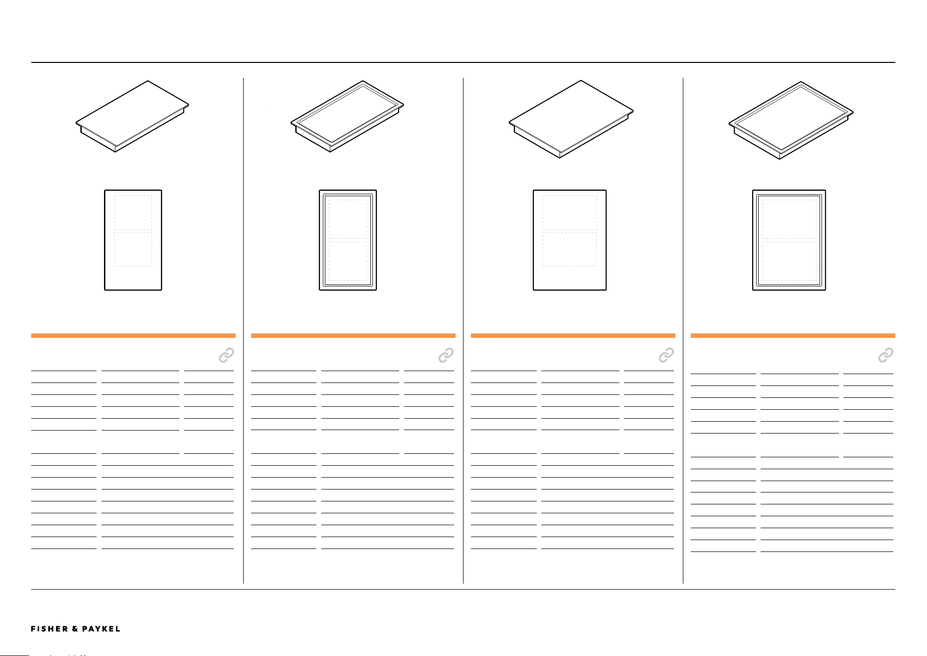
OVERVIEW
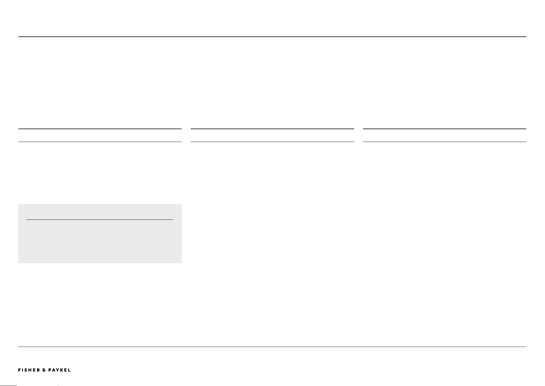
Create the ultimate culinary solution with our Series 9 and 11
modular cooktops. Using the dierent induction, teppan,
ventilation and gas modules, you can customize the cooking
area at the scale and format best suited to architectural plan
and user needs. Fusing precise induction technology with
innovative design, these modules are crafted to seamlessly
work together for perfect results.
FEATURES
1 Tailor the cooking space by pairing primary induction
cooktop modules with complementary auxiliary cooktops,
downdraft ventilation and gas on glass modules.
2 Control the auxiliary modular suite from the primary cooktop
using a large intuitive touchscreen.
3 Each module is designed to fit flush or raised with the
countertop for complete design freedom.
4 SmartHQ™ app connectivity to monitor product
and cook status.
CI152DB1
Auxiliary Modular Induction Cooktop, 15", 2 Zones with
SmartZone
CIT122DX1
Auxiliary Modular Teppanyaki Cooktop, 12", 2 Zones
CIT152DX1
Auxiliary Modular Teppanyaki Cooktop, 15", 2 Zones
AUXILIARY MoDULAR VENTILATIoN
No user interface. Controlled via paired primary cooktop.
CD5DB1
Auxiliary Modular Ventilation, 5", Duct Out
GAS oN GLASS MoDULAR CooKToP
Dial control, independently controlled.
CG151DLPGB5
Gas on Glass Modular Cooktop, 15", LPG
CG151DNGGB5
Gas on Glass Modular Cooktop, 15", Natural Gas
ACCESSoRIES
WTSC1
Wireless Temperature Sensor (1x included per Primary Modular
Induction Cooktop. Also available to purchase separately).
oAD225X12
Mainbox Outlet Adapter, 2.25" x 12"
oAB225X12
Blower Outlet Adapter, 2.25" x 12"
KRECIRCDDFT
Recirculation Kit
SPECIFICATION GUIDE | MODULAR COOKTOPS CI152DTT | CI244DTT | CI304DTT | CI365DTT | CI122D | CI152D | CIT122DX1 | CIT152DX1 | CD5D
5 Wireless Temperature Sensor precisely monitors and controls
cooking in real time, for complete control.*
6 Poach, Sous Vide and other Cook by Method functions
are available on product, when using the Wireless
Temperature Sensor.
7 Gas on Glass is independently controlled via a manual dial for
precise and flexible cooking options
* Selected models only.
PRODUCT OVERVIEW
PRIMARY MoDULAR INDUCTIoN CooKToPS
With touchscreen user interface
CI152DTTB1
Primary Modular Induction Cooktop, 15", 2 Zones with
SmartZone
CI244DTTB1
Primary Modular Induction Cooktop, 24", 4 Zones with
SmartZone
CI304DTTB1
Primary Modular Induction Cooktop, 30", 4 Zones with
SmartZone
CI365DTTB1
Primary Modular Induction Cooktop, 36", 5 Zones with
SmartZone
AUXILIARY MoDULAR CooKToPS
No user interface. Controlled via paired primary cooktop.
CI122DB1
Auxiliary Modular Induction Cooktop, 12", 2 Zones with
SmartZone
<< CONTENTS
© FISHER & PAYKEL LIMITED 2025 PAGE 590003312C PLANNING GUIDE MoDULAR CooKToPS VERSIoN C - MAY 2025
The models shown in this Planning Guide may not be available in all markets and are subject to change at any time. Product specifications may vary from those shown. This Planning Guide should not be used as installation guidance for any product. Further information is required to safely and correctly install the
products featured here. Specific installation guidance will be available with the product on delivery and on our website fisherpaykel.com
PRIMARY MODULES
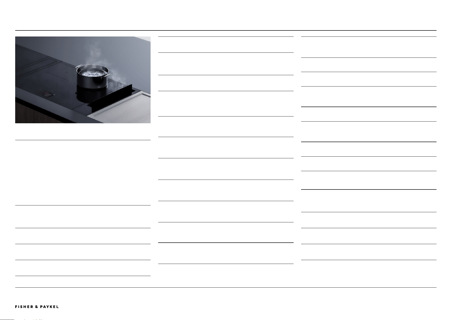
PRIMARY MODULAR INDUCTION COOKTOP, 15",
2 ZONES WITH SMARTZONE
Model no:
CI152DTTB1
Dimensions
W x D x H
in
mm
Product
15 5/32 x 20 7/8 x 2 7/16
385 x 530 x 62
Glass
15 5/32 x 20 7/8 x 1/4
385 x 530 x 6
Proud cutout
13 11/16 x 19 31/32
347 x 507
Flush cutout
13 11/16 x 20 1/32
347 x 509
Flush recess
15 5/16 x 21 1/32 x 1/4
389 x 534 x 6.5
Power Requirements
Supply
208 / 240 V, 60 Hz
Service
15 A
Connection
No plug, flex cord with stripped ends
Power Cable
74 13/16" (1900mm)
Weight
18lb / 8kg
PRIMARY MODULAR INDUCTION COOKTOP, 24",
4 ZONES WITH SMARTZONE
Model no:
CI244DTTB1
Dimensions
W x D x H
in
mm
Product
23 5/8 x 20 7/8 x 3 1/2
600 x 530 x 89
Glass
23 5/8 x 20 7/8 x 1/4
600 x 530 x 6
Proud cutout
22 1/8 x 19 31/32
562 x 507
Flush cutout
22 1/8 x 20 1/32
562 x 509
Flush recess
23 25/32 x 21 1/32 x 1/4
604 x 534 x 6.5
Power Requirements
Supply
208 / 240 V, 60 Hz
Service
30 A
Connection
No plug, flex metal conduit with stripped ends
Power Cable
54 5/16" (1380mm)
Weight
31lb / 14kg
PRIMARY MODULAR INDUCTION COOKTOP, 30",
4 ZONES WITH SMARTZONE
Model no:
CI304DTTB1
Dimensions
W x D x H
in
mm
Product
29 15/16 x 20 7/8 x 3 1/2
760 x 530 x 89
Glass
29 15/16 x 20 7/8 x 1/4
760 x 530 x 6
Proud cutout
28 7/16 x 19 31/32
722 x 507
Flush cutout
28 7/16 x 20 1/32
722 x 509
Flush recess
30 3/32 x 21 1/32 x 1/4
764 x 534 x 6.5
Power Requirements
Supply
208 / 240 V, 60 Hz
Service
30 A
Connection
No plug, flex metal conduit with stripped ends
Power Cable
54 5/16" (1380mm)
Weight
36lb / 16kg
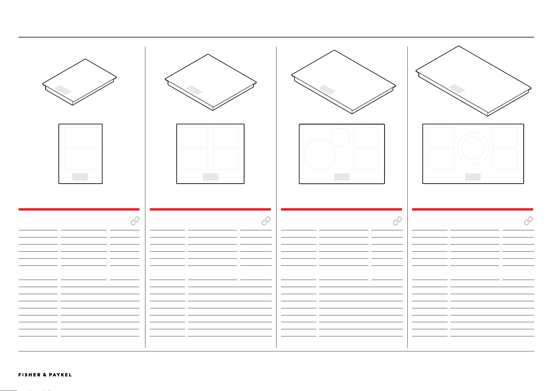
PRIMARY MODULAR INDUCTION COOKTOP, 36",
5 ZONES WITH SMARTZONE
Model no:
CI365DTTB1
Dimensions
W x D x H
in
mm
Product
35 7/16 x 20 7/8 x 3 1/2
900 x 530 x 89
Glass
35 7/16 x 20 7/8 x 1/4
900 x 530 x 6
Proud cutout
33 15/16 x 19 31/32
862 x 507
Flush cutout
33 15/16 x 20 1/32
862 x 509
Flush recess
35 19/32 x 21 1/32 x 1/4
904 x 534 x 6.5
Power Requirements
Supply
208 / 240 V, 60 Hz
Service
45 A
Connection
No plug, flex metal conduit with stripped ends
Power Cable
54 5/16" (1380mm)
Weight
43lb / 20kg
PRODUCT SPECIFICATIONS | MODULAR COOKTOPS
<< CONTENTS
© FISHER & PAYKEL LIMITED 2025 PAGE 690003312C PLANNING GUIDE MoDULAR CooKToPS VERSIoN C - MAY 2025
The models shown in this Planning Guide may not be available in all markets and are subject to change at any time. Product specifications may vary from those shown. This Planning Guide should not be used as installation guidance for any product. Further information is required to safely and correctly install the
products featured here. Specific installation guidance will be available with the product on delivery and on our website fisherpaykel.com
AUXILIARY MODULES
AUXILIARY MODULAR INDUCTION COOKTOP, 12",
2 ZONES WITH SMARTZONE
Model no:
CI122DB1
Dimensions
W x D x H
in
mm
Product
11 13/16 x 20 7/8 x 2 7/16
300 x 530 x 62
Glass
11 13/16 x 20 7/8 x 1/4
300 x 530 x 6
Proud cutout
10 5/16 x 19 31/32
262 x 507
Flush cutout
10 5/16 x 20 1/32
262 x 509
Flush recess
11 31/32 x 21 1/32 x 1/4
304 x 534 x 6.5
Power Requirements
Supply
208 / 240 V, 60 Hz
Service
15 A
Connection
No plug, flex cord with stripped ends
Power Cable
74 13/16" (1900mm)
Weight
15lb / 7kg
AUXILIARY MODULAR INDUCTION COOKTOP, 15",
2 ZONES WITH SMARTZONE
Model no:
CI152DB1
Dimensions
W x D x H
in
mm
Product
15 5/32 x 20 7/8 x 2 7/16
385 x 530 x 62
Glass
15 5/32 x 20 7/8 x 1/4
385 x 530 x 6
Proud cutout
13 11/16 x 19 31/32
347 x 507
Flush cutout
13 11/16 x 20 1/32
347 x 509
Flush recess
15 5/16 x 21 1/32 x 1/4
389 x 534 x 6.5
Power Requirements
Supply
208 / 240 V, 60 Hz
Service
15 A
Connection
No plug, flex cord with stripped ends
Power Cable
74 13/16" (1900mm)
Weight
18lb / 8kg
AUXILIARY MODULAR TEPPANYAKI COOKTOP, 15",
2 ZONES
Model no:
CIT152DX1
Dimensions
W x D x H
in
mm
Product
15 5/32 x 20 7/8 x 2 15/16
385 x 530 x 74
Plate
15 5/32 x 20 7/8 x 1/4
385 x 530 x 6
Proud cutout
13 11/16 x 19 31/32
347 x 507
Flush cutout
13 11/16 x 20 1/32
347 x 509
Flush recess
15 5/16 x 21 1/32 x 1/4
389 x 534 x 6.5
Power Requirements
Supply
208 / 240 V, 60 Hz
Service
15 A
Connection
No plug, flex cord with stripped ends
Power Cable
74 13/16" (1900mm)
Weight
32lb / 15kg
AUXILIARY MODULAR TEPPANYAKI COOKTOP, 12",
2 ZONES
Model no:
CIT122DX1
Dimensions
W x D x H
in
mm
Product
11 13/16 x 20 7/8 x 2 15/16
300 x 530 x 74
Plate
11 13/16 x 20 7/8 x 1/4
300 x 530 x 6
Proud cutout
10 5/16 x 19 31/32
262 x 507
Flush cutout
10 5/16 x 20 1/32
262 x 509
Flush recess
11 31/32 x 21 1/32 x 1/4
304 x 534 x 6.5
Power Requirements
Supply
208 / 240 V, 60 Hz
Service
15 A
Connection
No plug, flex cord with stripped ends
Power Cable
74 13/16" (1900mm)
Weight
27lb / 12kg
PRODUCT SPECIFICATIONS | MODULAR COOKTOPS
<< CONTENTS

© FISHER & PAYKEL LIMITED 2025 PAGE 790003312C PLANNING GUIDE MoDULAR CooKToPS VERSIoN C - MAY 2025
The models shown in this Planning Guide may not be available in all markets and are subject to change at any time. Product specifications may vary from those shown. This Planning Guide should not be used as installation guidance for any product. Further information is required to safely and correctly install the
products featured here. Specific installation guidance will be available with the product on delivery and on our website fisherpaykel.com
GAS ON GLASS MODULAR COOKTOP, 15"
Model no:
CG151DLPGB5 LPG
CG151DNGGB5 Natural Gas
Dimensions
W x D x H
in
mm
Product (excl. trivets)
15 5/32 x 20 7/8 x 2 9/16
385 x 530 x 65
Glass
15 5/32 x 20 7/8 x 1/4
385 x 530 x 6
Proud cutout
13 11/16 x 19 31/32
347 x 507
Flush cutout
13 11/16 x 20 1/32
347 x 509
Flush recess
15 5/16 x 21 1/32 x 1/4
389 x 534 x 6.5
Power Requirements
Supply
120 V, 60 Hz
Service
15 A
Connection
Plug
Gas Requirements
Supply
1/2" BSP minimum internal Ø 10mm flex line
Inlet
1/2" BSP
Weight
18lb / 8kg
AUXILIARY MODULES
AUXILIARY MODULAR VENTILATION, 5"
Model no:
CD5DB1
Dimensions
W x D x H
in
mm
Product
5 1/8 x 20 7/8 x 7 3/8
130 x 530 x 186
Glass
5 1/8 x 20 7/8 x 1/4
130 x 530 x 6
Proud cutout
3 7/8 x 19 31/32
98 x 507
Flush cutout
3 7/8 x 20 1/32
98 x 509
Flush recess
5 9/32 x 21 1/32 x 1/4
134 x 534 x 6.5
Power Requirements
Supply
120 V, 60 Hz
Service
5 A
Connection
Flex cord, 3-pin plug
Power Cable
28" (720mm)
Weight
7lb / 3kg
* Must be installed in combined cutout with cooktop
PRODUCT SPECIFICATIONS | MODULAR COOKTOPS
ELECTRICAL SERVICE FOR MULTIPLE PRODUCT INSTALLS
Where multiple products are being installed together, it is possible to use a smaller local distribution board,
rather than running multiple separate lines. For example, 2 x 15 A modules can be connected via a single 30
A breaker.
This cooktop must be connected to the mains power supply only by a suitably
qualified person.
<< CONTENTS

© FISHER & PAYKEL LIMITED 2025 PAGE 890003312C PLANNING GUIDE MoDULAR CooKToPS - VERSIoN C - MAY 2025
DATA SHEETS
<< CONTENTS
© FISHER & PAYKEL LIMITED 2025 PAGE 990003312C PLANNING GUIDE MoDULAR CooKToPS VERSIoN C - MAY 2025
IMPORTANT NOTE: Throughout this guide, dimensions may vary by ±2mm (1/16''). Please
read the installation manual for detailed information on installing the product. For full
installation instructions & specifications visit fisherpaykel.com
INDICATES CABINETRY / PRODUCT DATUM -------------------------
INDICATES CABINETRY CLEARANCES --------------------------------
INDICATES CUTOUT -------------------------------------------------------
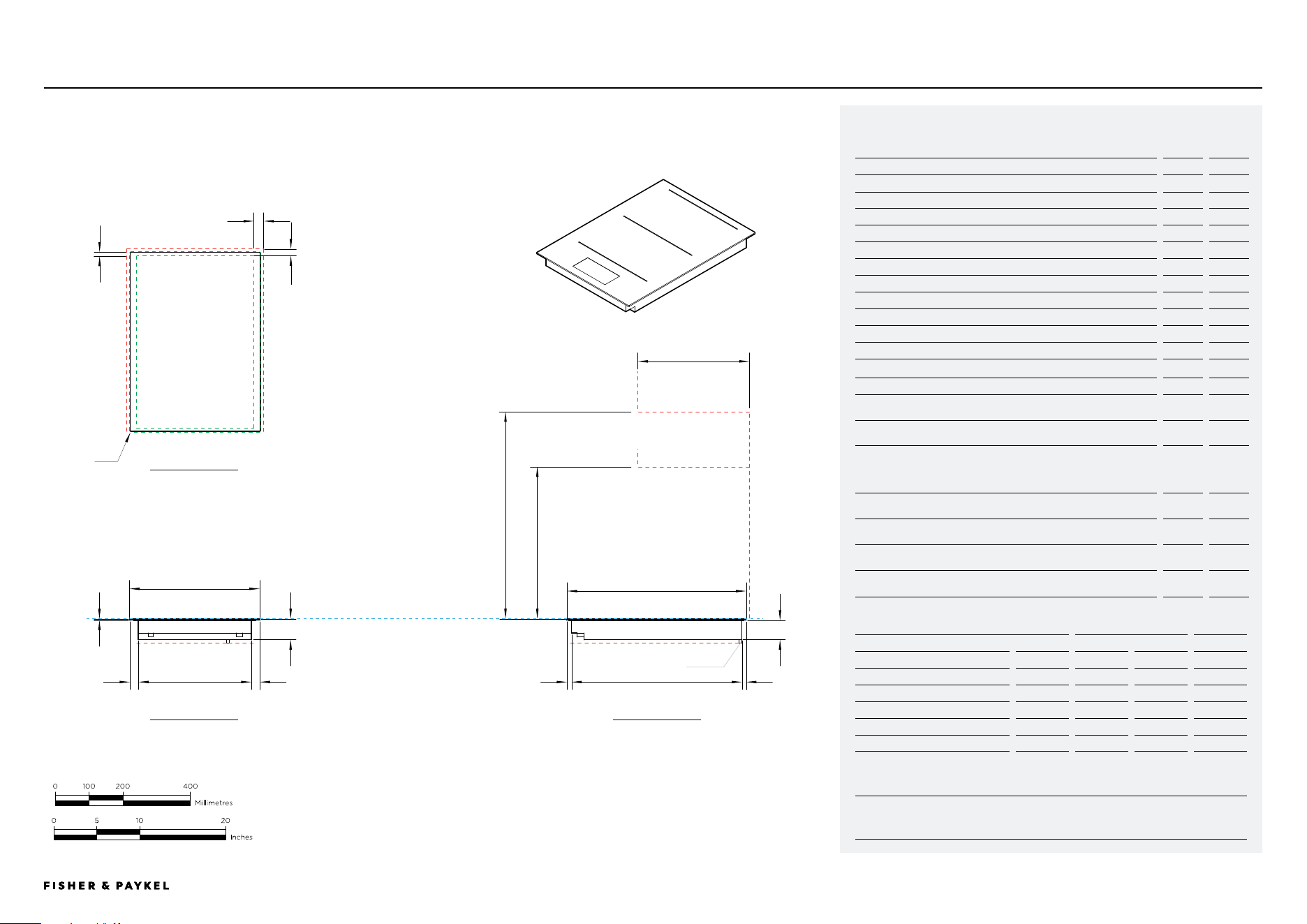
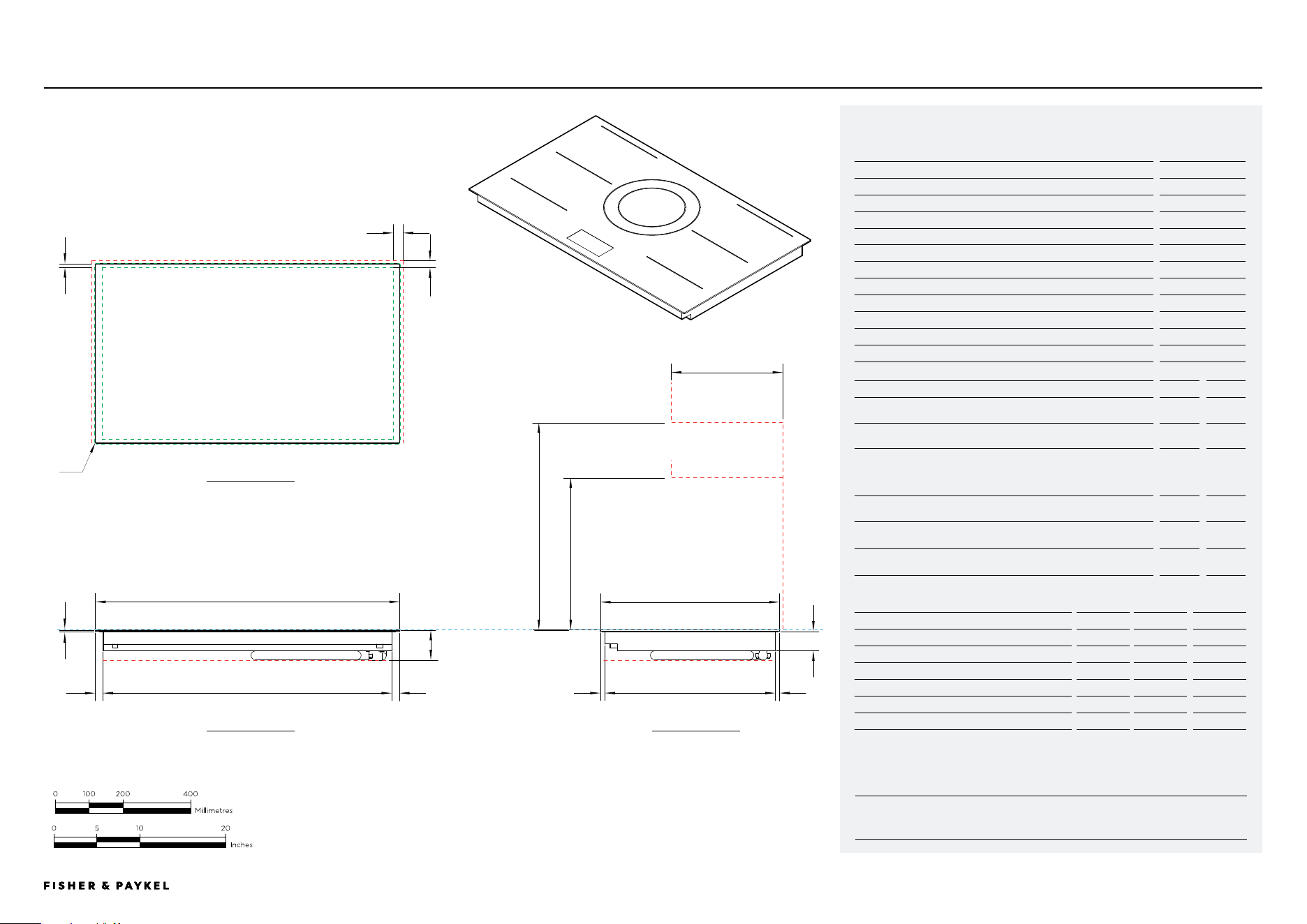
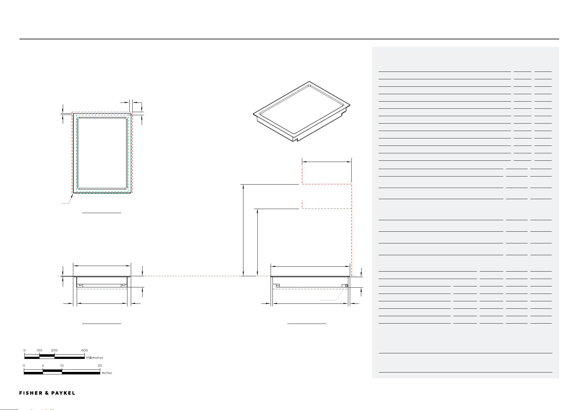
CI152DTTB1
Model no:
Primary Modular Induction Cooktop, 15", 2 Zones with SmartZone, Black - CI152DTTB1
Product Dimensions
in
mm
A Overall height of cooktop
2 7/16
62
B Overall width of cooktop
15 5/32
385
C Overall depth of cooktop
20 7/8
530
D Height of cooktop glass (includes flange and tape)
1/4
6
E Corner radius of glass
1/16
2
F Height of chassis
2 3/16
56
G Width of chassis
13 1/8
334
H Depth of chassis
19 13/16
504
I Width from side edges of cooktop to chassis
1
26
J Depth from front edge of cooktop to chassis
17/32
13.5
K Depth from back edge of cooktop to chassis
1/2
12.5
Product Clearances
in
mm
L Minimum clearance from side edges of cutout to nearest
combustible surface
1 3/16
29
M Minimum clearance from rear edge of cutout to nearest
combustible surface
7/ 8 21
N Minimum clearance from glass cook surface to:
Overhead cabinet centered above the cooktop (unprotected)
Overhead cabinet centered above the cooktop (protected)
Range hood
24
610
O Minimum clearance from glass cook surface to overhead cabinet
not directly above cooktop
17 3/4
450
P Maximum depth of unprotected overhead cabinets
from rear clearance
13
330
Minimum ventilation gap between bottom of countertop and top of
cabinetry fronts (not shown)
5/32
4
Minimum clearance from glass cook surface to top of any appliances,
companion product or obstruction below cooktop
2 7/ 8 72
NOTE: The oven installed below the cooktop MUST have a cooling fan. It is important that the induction cooktop
receives adequate air supply. For ventilation requirements please refer to the installation manual.
Cutout Dimensions*
Proud in
Proud mm
Flush in
Flush mm
Overall width of cutout
13 11/16
347
13 11/16
347
Overall depth of cutout
19 31/32
507
20 1/32
509
Overall width of recess
-
-
15 5/16
389
Overall depth of recess
-
-
21 1/32
534
Overall height of recess
-
-
1/4
6.5
Recess corner radius
-
-
5/32
4
*Note cutout position is centered to the cooktop.
DATA SHEETS | MODULAR COOKTOPS
K
L
e
m
d
i
a
ig
n o
j
F
k
h
p
CLEARANCE: RANGEHOOD,
OVERHEAD CABINET
CLEARANCE: OVERHEAD
CABINET NOT DIRECTLY ABOVE
CLEARANCE: BELOW COOKTOPCLEARANCE: BELOW COOKTOP
DATUM: TOP OF COOKSURFACE
CLEARANCE: COMBUSTIBLE SURFACE
CLEARANCE: COMBUSTIBLE SURFACE
b
15 5/32"
c
20 7/8"
POWER OUTLET
PRoFILE VIEW
FRoNT VIEW
PLAN VIEW
<< CONTENTS
© FISHER & PAYKEL LIMITED 2025 PAGE 1090003312C PLANNING GUIDE MoDULAR CooKToPS VERSIoN C - MAY 2025
IMPORTANT NOTE: Throughout this guide, dimensions may vary by ±2mm (1/16''). Please
read the installation manual for detailed information on installing the product. For full
installation instructions & specifications visit fisherpaykel.com
INDICATES CABINETRY / PRODUCT DATUM -------------------------
INDICATES CABINETRY CLEARANCES --------------------------------
INDICATES CUTOUT -------------------------------------------------------
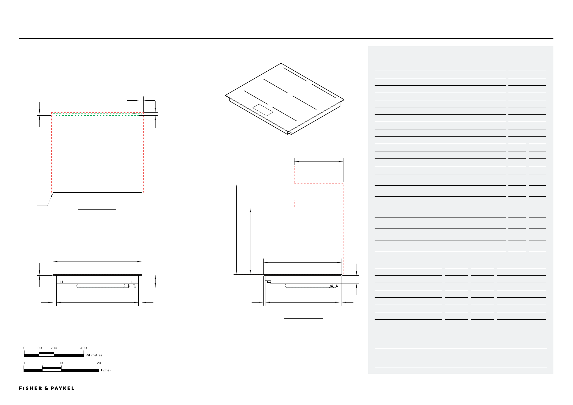
CI244DTTB1
Model no:
Primary Modular Induction Cooktop, 24", 4 Zones with SmartZone, Black - CI244DTTB1
Product Dimensions
in
mm
A Overall height of cooktop
3 1/2
89
B Overall width of cooktop
23 5/8
600
C Overall depth of cooktop
20 7/8
530
D Height of cooktop glass (includes flange and tape)
1/4
6
E Corner radius of glass
1/16
2
F Height of chassis
2 3/16
56
G Width of chassis
21 13/16
554
H Depth of chassis
19 13/16
504
I Width from side edges of cooktop to chassis
1
23
J Depth from front edge of cooktop to chassis
17/32
13.5
K Depth from back edge of cooktop to chassis
1/2
12.5
Product Clearances
in
mm
L Minimum clearance from side edges of cutout to nearest
combustible surface
1 3/16
29
M Minimum clearance from rear edge of cutout to nearest
combustible surface
7/ 8
21
N Minimum clearance from glass cook surface to:
Overhead cabinet centered above the cooktop (unprotected)
Overhead cabinet centered above the cooktop (protected)
Range hood
24
610
O Minimum clearance from glass cook surface to overhead cabinet
not directly above cooktop
17 3/4
450
Minimum ventilation gap between bottom of countertop and top of
cabinetry fronts (not shown)
5/32
4
Minimum clearance from glass cook surface to top of any appliances,
companion product or obstruction below cooktop
3 5/8
91
NOTE: The oven installed below the cooktop MUST have a cooling fan. It is important that the induction cooktop
receives adequate air supply. For ventilation requirements please refer to the installation manual.
Cutout Dimensions*
proud in
proud mm
flush in
flush mm
Overall width of cutout
22 1/8
562
22 1/8
562
Overall depth of cutout
19 31/32
507
20 1/32
509
Overall width of recess
-
-
23 25/32
604
Overall depth of recess
-
-
21 1/32
534
Overall height of recess
-
-
1/4
6.5
Recess corner radius
-
-
5/32
4
*Note cutout position is centered to the cooktop.
DATA SHEETS | MODULAR COOKTOPS
K
L
e
m
d
i
a
i
g
n o
j
F
k
h
p
CLEARANCE: RANGEHOOD,
OVERHEAD CABINET
CLEARANCE: OVERHEAD
CABINET NOT DIRECTLY ABOVE
CLEARANCE: BELOW COOKTOP
CLEARANCE: BELOW COOKTOP
DATUM: TOP OF COOKSURFACE
CLEARANCE: COMBUSTIBLE SURFACE
CLEARANCE: COMBUSTIBLE SURFACE
b
23 5/8"
c
20 7/8"
PRoFILE VIEW
FRoNT VIEW
PLAN VIEW
<< CONTENTS
© FISHER & PAYKEL LIMITED 2025 PAGE 1190003312C PLANNING GUIDE MoDULAR CooKToPS VERSIoN C - MAY 2025
IMPORTANT NOTE: Throughout this guide, dimensions may vary by ±2mm (1/16''). Please
read the installation manual for detailed information on installing the product. For full
installation instructions & specifications visit fisherpaykel.com
INDICATES CABINETRY / PRODUCT DATUM -------------------------
INDICATES CABINETRY CLEARANCES --------------------------------
INDICATES CUTOUT -------------------------------------------------------
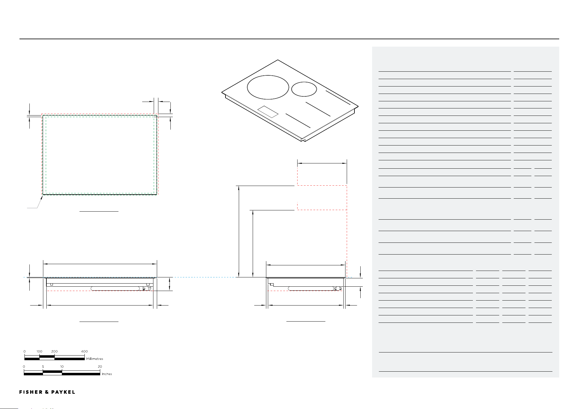
CI304DTTB1
Model no:
Primary Modular Induction Cooktop, 30", 4 Zones with SmartZone, Black - CI304DTTB1
Product Dimensions
in
mm
A Overall height of cooktop
3 1/2
89
B Overall width of cooktop
29 15/16
760
C Overall depth of cooktop
20 7/8
530
D Height of cooktop glass (includes flange and tape)
1/4
6
E Corner radius of glass
1/16
2
F Height of chassis
2 3/16
56
G Width of chassis
28 1/8
714
H Depth of chassis
19 13/16
504
I Width from side edges of cooktop to chassis
1
23
J Depth from front edge of cooktop to chassis
17/32
14
K Depth from back edge of cooktop to chassis
1/2
13
Product Clearances
in
mm
L Minimum clearance from side edges of cutout to nearest
combustible surface
1 3/16
29
M Minimum clearance from rear edge of cutout to nearest
combustible surface
7/ 8
21
N Minimum clearance from glass cook surface to:
Overhead cabinet centered above the cooktop (unprotected)
Overhead cabinet centered above the cooktop (protected)
Range hood
24
610
O Minimum clearance from glass cook surface to overhead cabinet
not directly above cooktop
17 3/4
450
Minimum ventilation gap between bottom of countertop and top of
cabinetry fronts (not shown)
5/32
4
Minimum clearance from glass cook surface to top of any appliances,
companion product or obstruction below cooktop
3 5/8
91
NOTE: The oven installed below the cooktop MUST have a cooling fan. It is important that the induction cooktop
receives adequate air supply. For ventilation requirements please refer to the installation manual.
Cutout Dimensions*
proud in
proud mm
flush in
flush mm
Overall width of cutout
28 7/16
722
28 7/16
722
Overall depth of cutout
19 31/32
507
20 1/32
509
Overall width of recess
-
-
30 3/32
764
Overall depth of recess
-
-
21 1/32
534
Overall height of recess
-
-
1/4
6.5
Recess corner radius
-
-
5/32
4
*Note cutout position is centered to the cooktop.
DATA SHEETS | MODULAR COOKTOPS
K
L
e
m
d
i
a
i
g
n o
j
F
k
h
p
CLEARANCE: RANGEHOOD,
OVERHEAD CABINET
CLEARANCE: OVERHEAD
CABINET NOT DIRECTLY
ABOVE
CLEARANCE: BELOW COOKTOP
CLEARANCE: BELOW COOKTOP
DATUM: TOP OF COOKSURFACE
CLEARANCE: COMBUSTIBLE SURFACE
CLEARANCE: COMBUSTIBLE SURFACE
b
29 15/16"
c
20 7/8"
PRoFILE VIEW
FRoNT VIEW
PLAN VIEW
<< CONTENTS
© FISHER & PAYKEL LIMITED 2025 PAGE 1290003312C PLANNING GUIDE MoDULAR CooKToPS VERSIoN C - MAY 2025
IMPORTANT NOTE: Throughout this guide, dimensions may vary by ±2mm (1/16''). Please
read the installation manual for detailed information on installing the product. For full
installation instructions & specifications visit fisherpaykel.com
INDICATES CABINETRY / PRODUCT DATUM -------------------------
INDICATES CABINETRY CLEARANCES --------------------------------
INDICATES CUTOUT -------------------------------------------------------
CI365DTTB1
Model no:
Primary Modular Induction Cooktop, 36", 5 Zones with SmartZone, Black - CI365DTTB1
Product Dimensions
in
mm
A Overall height of cooktop
3 1/2
89
B Overall width of cooktop
35 7/16
900
C Overall depth of cooktop
20 7/8
530
D Height of cooktop glass (includes flange and tape)
1/4
6
E Corner radius of glass
1/16
2
F Height of chassis
2 3/16
56
G Width of chassis
33 5/8
854
H Depth of chassis
19 13/16
504
I Width from side edges of cooktop to chassis
1
23
J Depth from front edge of cooktop to chassis
17/32
14
K Depth from back edge of cooktop to chassis
1/2
13
Product Clearances
in
mm
L Minimum clearance from side edges of cutout to nearest
combustible surface
1 3/16
29
M Minimum clearance from rear edge of cutout to nearest
combustible surface
7/ 8
21
N Minimum clearance from glass cook surface to:
Overhead cabinet centered above the cooktop (unprotected)
Overhead cabinet centered above the cooktop (protected)
Range hood
24
610
O Minimum clearance from glass cook surface to overhead cabinet
not directly above cooktop
17 3/4
450
Minimum ventilation gap between bottom of countertop and top of
cabinetry fronts (not shown)
5/32
4
Minimum clearance from glass cook surface to top of any appliances,
companion product or obstruction below cooktop
3 5/8
91
NOTE: The oven installed below the cooktop MUST have a cooling fan. It is important that the induction cooktop
receives adequate air supply. For ventilation requirements please refer to the installation manual.
Cutout Dimensions*
proud in
proud mm
flush in
flush mm
Overall width of cutout
33 15/16
862
33 15/16
862
Overall depth of cutout
19 31/32
507
20 1/32
509
Overall width of recess
-
-
35 19/32
904
Overall depth of recess
-
-
21 1/32
534
Overall height of recess
-
-
1/4
6.5
Recess corner radius
-
-
5/32
4
*Note cutout position is centered to the cooktop.
DATA SHEETS | MODULAR COOKTOPS
K
L
e
m
d
i
a
ig
n o
j
F
k
h
p
CLEARANCE: RANGEHOOD,
OVERHEAD CABINET
CLEARANCE: OVERHEAD
CABINET NOT DIRECTLY ABOVE
CLEARANCE: BELOW COOKTOP
CLEARANCE: BELOW COOKTOP
DATUM: TOP OF
COOKSURFACE
CLEARANCE: COMBUSTIBLE SURFACE
CLEARANCE: COMBUSTIBLE SURFACE
b
35 7/16"
c
20 7/8"
PRoFILE VIEW
FRoNT VIEW
PLAN VIEW
<< CONTENTS
© FISHER & PAYKEL LIMITED 2025 PAGE 1390003312C PLANNING GUIDE MoDULAR CooKToPS VERSIoN C - MAY 2025
IMPORTANT NOTE: Throughout this guide, dimensions may vary by ±2mm (1/16''). Please
read the installation manual for detailed information on installing the product. For full
installation instructions & specifications visit fisherpaykel.com
INDICATES CABINETRY / PRODUCT DATUM -------------------------
INDICATES CABINETRY CLEARANCES --------------------------------
INDICATES CUTOUT -------------------------------------------------------
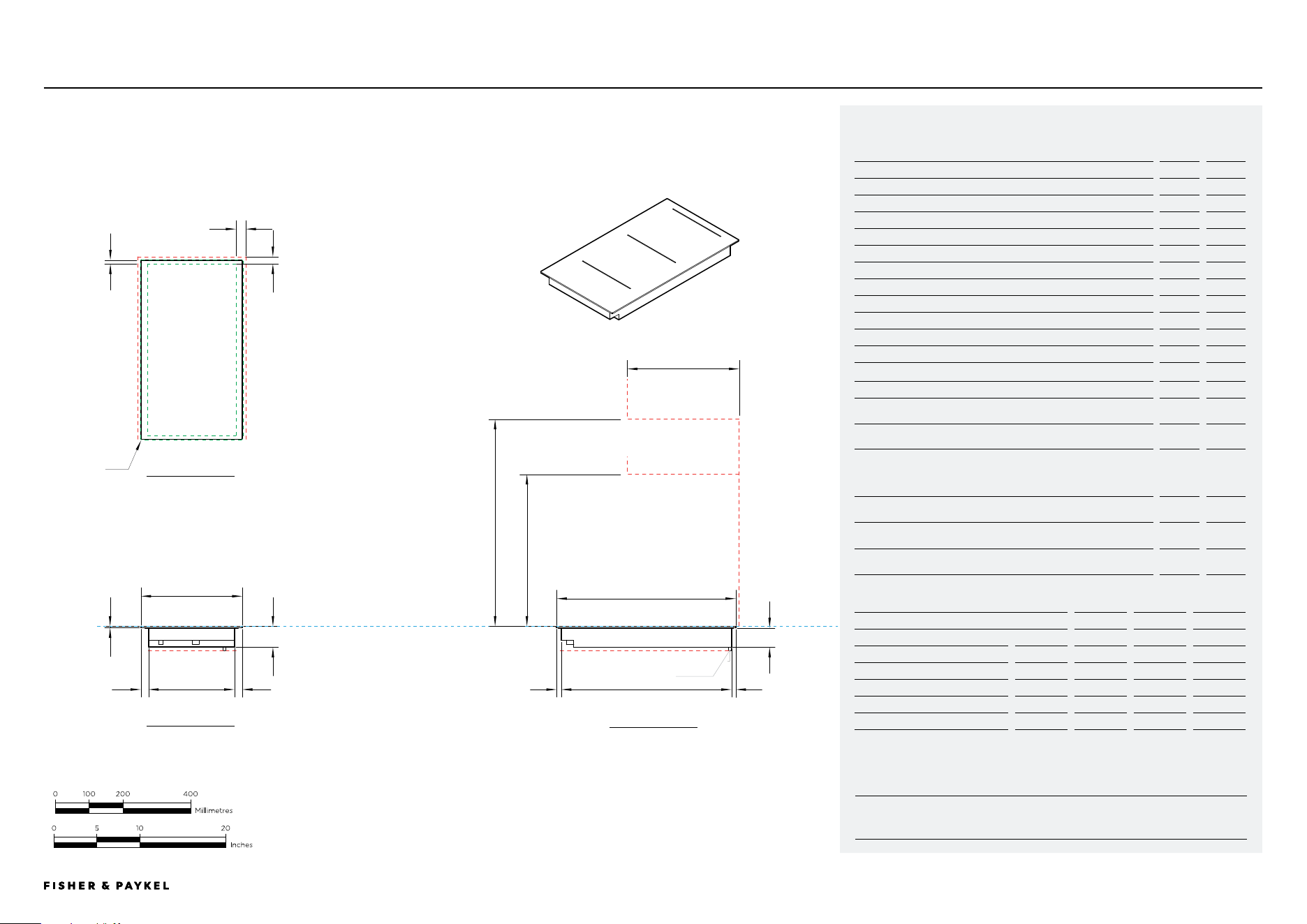
CI122DB1
Model no:
Auxiliary Modular Induction Cooktop, 12", 2 Zones with SmartZone, Black - CI122DB1
Product Dimensions
in
mm
A Overall height of cooktop
2 7/16
62
B Overall width of cooktop
11 13/16
300
C Overall depth of cooktop
20 7/8
530
D Height of cooktop glass (includes flange and tape)
1/4
6
E Corner radius of glass
1/16
2
F Height of chassis
2 3/16
56
G Width of chassis
10
254
H Depth of chassis
19 13/16
504
I Width from side edges of cooktop to chassis
1
26
J Depth from front edge of cooktop to chassis
17/32
13.5
K Depth from back edge of cooktop to chassis
1/2
12.5
Product Clearances
in
mm
L Minimum clearance from side edges of cutout to nearest
combustible surface
1 3/16
29
M Minimum clearance from rear edge of cutout to nearest
combustible surface
7/ 8
21
N Minimum clearance from glass cook surface to:
Overhead cabinet centered above the cooktop (unprotected)
Overhead cabinet centered above the cooktop (protected)
Range hood
24
610
O Minimum clearance from glass cook surface to overhead cabinet
not directly above cooktop
17 3/4
450
Minimum ventilation gap between bottom of countertop and top of
cabinetry fronts (not shown)
5/32
4
Minimum clearance from glass cook surface to top of any appliances,
companion product or obstruction below cooktop
2 7/ 8
72
NOTE: The oven installed below the cooktop MUST have a cooling fan. It is important that the induction cooktop
receives adequate air supply. For ventilation requirements please refer to the installation manual.
Cutout Dimensions*
proud in
proud mm
flush in
flush mm
Overall width of cutout
10 5/16
262
10 5/16
262
Overall depth of cutout
19 31/32
507
20 1/32
509
Overall width of recess
-
-
15 5/16
389
Overall depth of recess
-
-
21 1/32
534
Overall height of recess
-
-
1/4
6.5
Recess corner radius
-
-
5/32
4
*Note cutout position is centered to the cooktop.
DATA SHEETS | MODULAR COOKTOPS
K
L
e
m
d
i
a
i
g
n o
j
F
k
h
p
CLEARANCE: RANGEHOOD,
OVERHEAD CABINET
CLEARANCE: OVERHEAD
CABINET NOT DIRECTLY ABOVE
CLEARANCE: BELOW COOKTOP
CLEARANCE: BELOW
COOKTOP
DATUM: TOP OF COOKSURFACE
CLEARANCE: COMBUSTIBLE SURFACE
CLEARANCE: COMBUSTIBLE
SURFACE
b
11 13/16"
c
20 7/8"
POWER OUTLET
PRoFILE VIEW
FRoNT VIEW
PLAN VIEW
<< CONTENTS
© FISHER & PAYKEL LIMITED 2025 PAGE 1490003312C PLANNING GUIDE MoDULAR CooKToPS VERSIoN C - MAY 2025
IMPORTANT NOTE: Throughout this guide, dimensions may vary by ±2mm (1/16''). Please
read the installation manual for detailed information on installing the product. For full
installation instructions & specifications visit fisherpaykel.com
INDICATES CABINETRY / PRODUCT DATUM -------------------------
INDICATES CABINETRY CLEARANCES --------------------------------
INDICATES CUTOUT -------------------------------------------------------
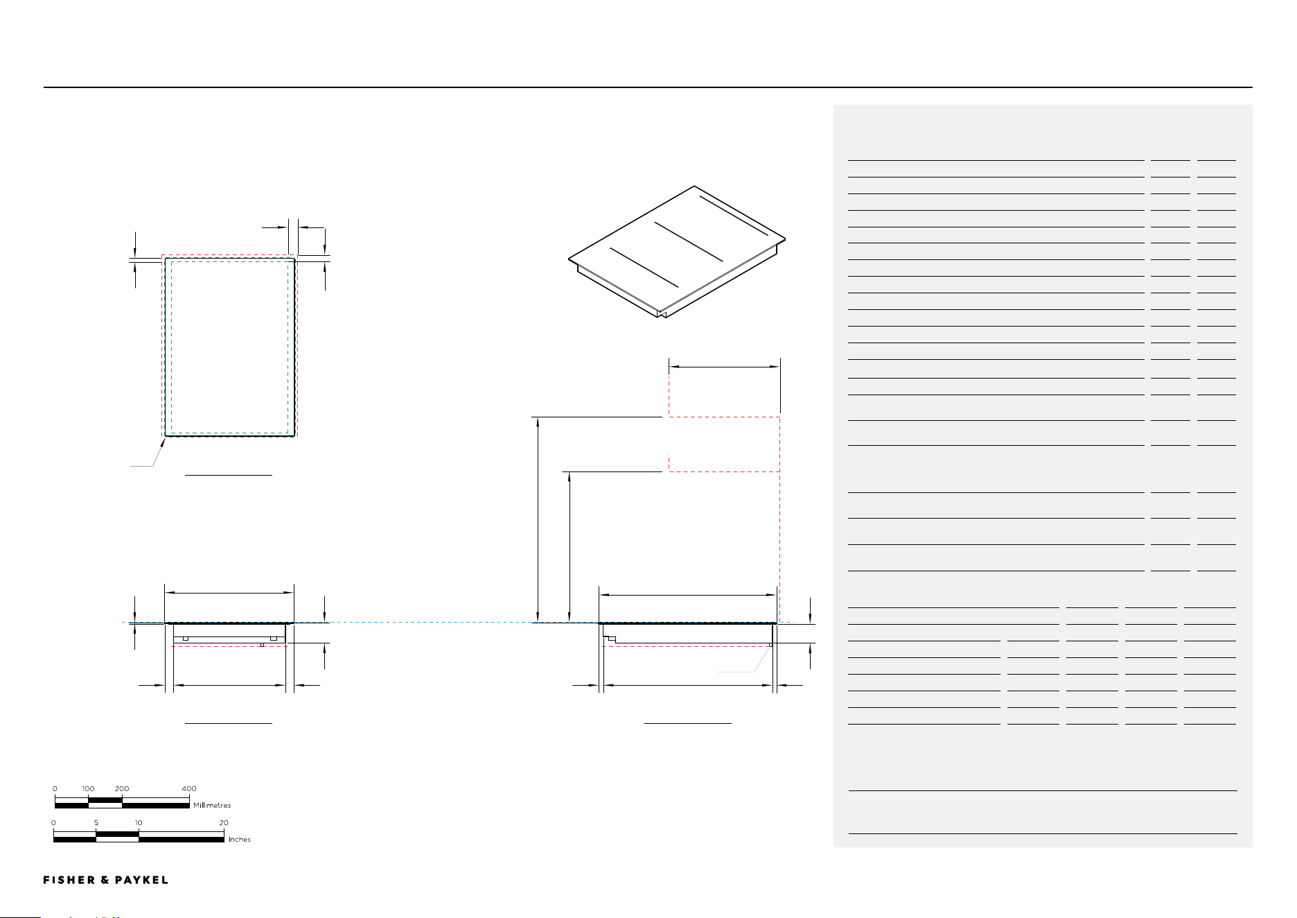
CIT122DX1
Model no:
Auxiliary Modular Teppanyaki Cooktop 12", 2 Zones - CIT122DX1
Product Dimensions
in
mm
A Overall height of cooktop
2 15/16
74
B Overall width of cooktop
11 13/16
300
C Overall depth of cooktop
20 7/8
530
D Height of stainless steel cook plate (includes flange and tape)
1/4
6
E Corner radius of stainless steel cook plate
1/16
2
F Height of chassis
2 11/16
68
G Width of chassis
9 7/ 8
251
H Depth of chassis
19 13/16
504
I Width from side edges of cooktop to chassis
1
24.5
J Depth from front edge of cooktop to chassis
17/32
13.5
K Depth from back edge of cooktop to chassis
1/2
12.5
Product Clearances
in
mm
L Minimum clearance from side edges of cutout to nearest
combustible surface
1 3/16
29
M Minimum clearance from rear edge of cutout to nearest
combustible surface
7/ 8
21
N Minimum clearance from stainless steel cook surface to:
Overhead cabinet centered above the cooktop (unprotected)
Overhead cabinet centered above the cooktop (protected)
Range hood
24
610
O Minimum clearance from cook surface to overhead cabinet not
directly above cooktop
17 3/4
450
Minimum ventilation gap between bottom of countertop and top of
cabinetry fronts (not shown)
5/32
4
Minimum clearance from cook surface to top of any appliances,
companion product or obstruction below cooktop
3 3/8
86
NOTE: The oven installed below the cooktop MUST have a cooling fan. It is important that the induction cooktop
receives adequate air supply. For ventilation requirements please refer to the installation manual.
Cutout Dimensions*
proud in
proud mm
flush in
flush mm
Overall width of cutout
10 5/16
262
10 5/16
262
Overall depth of cutout
19 31/32
507
20 1/32
509
Overall width of recess
-
-
15 5/16
389
Overall depth of recess
-
-
21 1/32
534
Overall height of recess
-
-
1/4
6.5
Recess corner radius
-
-
5/32
4
*Note cutout position is centered to the cooktop.
DATA SHEETS | MODULAR COOKTOPS
K
L
e
m
d
i
a
i
g
n o
j
F
k
h
p
CLEARANCE: RANGEHOOD,
OVERHEAD CABINET
CLEARANCE: OVERHEAD
CABINET NOT DIRECTLY ABOVE
CLEARANCE: BELOW COOKTOPCLEARANCE: BELOW
COOKTOP
DATUM: TOP OF COOKSURFACE
CLEARANCE: COMBUSTIBLE SURFACE
CLEARANCE: COMBUSTIBLE
SURFACE
b
11 13/16"
c
20 7/8"
POWER OUTLET
PRoFILE VIEW
FRoNT VIEW
PLAN VIEW
<< CONTENTS
© FISHER & PAYKEL LIMITED 2025 PAGE 1590003312C PLANNING GUIDE MoDULAR CooKToPS VERSIoN C - MAY 2025
IMPORTANT NOTE: Throughout this guide, dimensions may vary by ±2mm (1/16''). Please
read the installation manual for detailed information on installing the product. For full
installation instructions & specifications visit fisherpaykel.com
INDICATES CABINETRY / PRODUCT DATUM -------------------------
INDICATES CABINETRY CLEARANCES --------------------------------
INDICATES CUTOUT -------------------------------------------------------
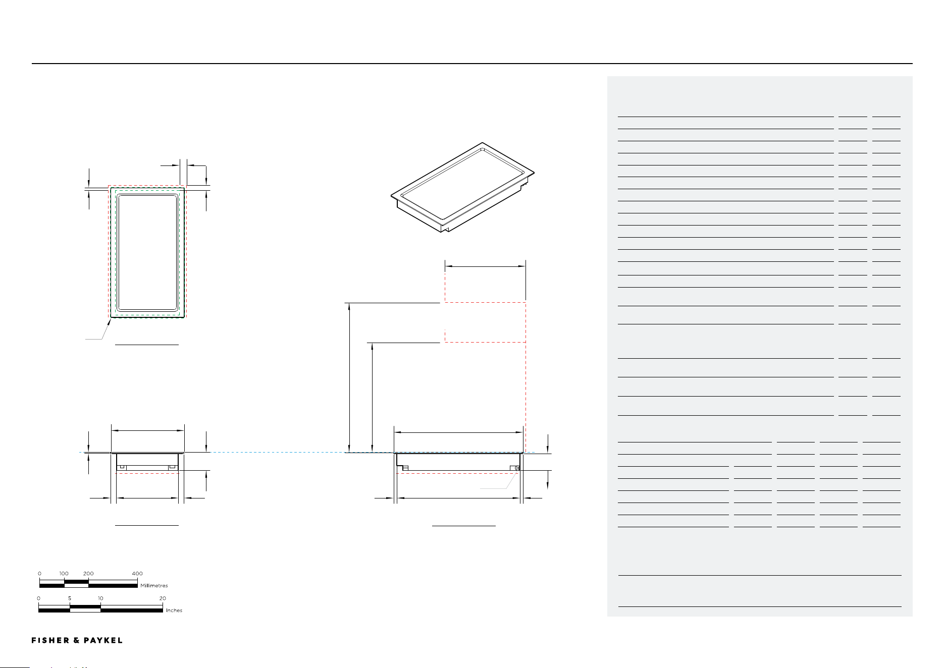
CI152DB1
Model no:
Auxiliary Modular Induction Cooktop, 15", 2 Zones with SmartZone, Black - CI152DB1
Product Dimensions
in
mm
A Overall height of cooktop
2 7/16
62
B Overall width of cooktop
15 5/32
385
C Overall depth of cooktop
20 7/8
530
D Height of cooktop glass (includes flange and tape)
1/4
6
E Corner radius of stainless steel
1/16
2
F Height of chassis
2 3/16
56
G Width of chassis
13 1/8
334
H Depth of chassis
19 13/16
504
I Width from side edges of cooktop to chassis
1
26
J Depth from front edge of cooktop to chassis
17/32
13.5
K Depth from back edge of cooktop to chassis
1/2
12.5
Product Clearances
in
mm
L Minimum clearance from side edges of cutout to nearest
combustible surface
1 3/16
29
M Minimum clearance from rear edge of cutout to nearest
combustible surface
7/ 8
21
N Minimum clearance from glass cook surface to:
Overhead cabinet centered above the cooktop (unprotected)
Overhead cabinet centered above the cooktop (protected)
Range hood
24
610
O Minimum clearance from glass cook surface to overhead cabinet
not directly above cooktop
17 3/4
450
Minimum ventilation gap between bottom of countertop and top of
cabinetry fronts (not shown)
5/32
4
Minimum clearance from glass cook surface to top of any appliances,
companion product or obstruction below cooktop
2 7/ 8
72
NOTE: The oven installed below the cooktop MUST have a cooling fan. It is important that the induction cooktop
receives adequate air supply. For ventilation requirements please refer to the installation manual.
Cutout Dimensions*
proud in
proud mm
flush in
flush mm
Overall width of cutout
13 11/16
347
13 11/16
347
Overall depth of cutout
19 31/32
507
20 1/32
509
Overall width of recess
-
-
15 5/16
389
Overall depth of recess
-
-
21 1/32
534
Overall height of recess
-
-
1/4
6.5
Recess corner radius
-
-
5/32
4
*Note cutout position is centered to the cooktop.
DATA SHEETS | MODULAR COOKTOPS
K
L
e
m
d
i
a
ig
n o
j
F
k
h
p
CLEARANCE: RANGEHOOD,
OVERHEAD CABINET
CLEARANCE: OVERHEAD
CABINET NOT DIRECTLY ABOVE
CLEARANCE: BELOW COOKTOPCLEARANCE: BELOW COOKTOP
DATUM: TOP OF COOKSURFACE
CLEARANCE: COMBUSTIBLE SURFACE
CLEARANCE: COMBUSTIBLE SURFACE
b
15 3/16"
c
20 7/8"
POWER OUTLET
PRoFILE VIEW
FRoNT VIEW
PLAN VIEW
<< CONTENTS
© FISHER & PAYKEL LIMITED 2025 PAGE 1690003312C PLANNING GUIDE MoDULAR CooKToPS VERSIoN C - MAY 2025
IMPORTANT NOTE: Throughout this guide, dimensions may vary by ±2mm (1/16''). Please
read the installation manual for detailed information on installing the product. For full
installation instructions & specifications visit fisherpaykel.com
INDICATES CABINETRY / PRODUCT DATUM -------------------------
INDICATES CABINETRY CLEARANCES --------------------------------
INDICATES CUTOUT -------------------------------------------------------
CIT152DX1
Model no:
Auxiliary Modular Teppanyaki Cooktop 15", 2 Zones - CIT152DX1
Product Dimensions
in
mm
A Overall height of cooktop
2 15/16
74
B Overall width of cooktop
15 5/32
385
C Overall depth of cooktop
20 7/8
530
D Height of stainless steel cook plate (includes flange and tape)
1/4
6
E Corner radius of stainless steel cook plate
1/16
2
F Height of chassis
2 11/16
68
G Width of chassis
13 1/8
336
H Depth of chassis
19 7/8
504
I Width from side edges of cooktop to chassis
1
26
J Depth from front edge of cooktop to chassis
17/32
13.5
K Depth from back edge of cooktop to chassis
1/2
12.5
Product Clearances
in
mm
L Minimum clearance from side edges of cutout to nearest
combustible surface
1 3/16
29
M Minimum clearance from rear edge of cutout to nearest
combustible surface
7/ 8
21
N Minimum clearance from stainless steel cook surface to:
Overhead cabinet centered above the cooktop (unprotected)
Overhead cabinet centered above the cooktop (protected)
Range hood
24
610
O Minimum clearance from cook surface to overhead cabinet not
directly above cooktop
17 3/4
450
Minimum ventilation gap between bottom of countertop and top
of cabinetry fronts (not shown)
5/32
4
Minimum clearance from cook surface to top of any appliances,
companion product or obstruction below cooktop
3 3/8
86
NOTE: The oven installed below the cooktop MUST have a cooling fan. It is important that the induction cooktop
receives adequate air supply. For ventilation requirements please refer to the installation manual.
Cutout Dimensions*
proud in
proud mm
flush in
flush mm
Overall width of cutout
13 11/16
347
13 11/16
347
Overall depth of cutout
19 31/32
507
20 1/32
509
Overall width of recess
-
-
15 5/16
389
Overall depth of recess
-
-
21 1/32
534
Overall height of recess
-
-
1/4
6.5
Recess corner radius
-
-
5/32
4
*Note cutout position is centered to the cooktop.
DATA SHEETS | MODULAR COOKTOPS
K
L
e
m
d
i
a
ig
n o
j
F
k
h
p
CLEARANCE: RANGEHOOD,
OVERHEAD CABINET
CLEARANCE: OVERHEAD
CABINET NOT DIRECTLY ABOVE
CLEARANCE: BELOW COOKTOP
CLEARANCE: BELOW COOKTOP
DATUM: TOP OF COOKSURFACE
CLEARANCE: COMBUSTIBLE SURFACE
CLEARANCE: COMBUSTIBLE SURFACE
b
15 3/16"
c
20 7/8"
POWER OUTLET
PRoFILE VIEW
FRoNT VIEW
PLAN VIEW
<< CONTENTS
© FISHER & PAYKEL LIMITED 2025 PAGE 1790003312C PLANNING GUIDE MoDULAR CooKToPS VERSIoN C - MAY 2025
IMPORTANT NOTE: Throughout this guide, dimensions may vary by ±2mm (1/16''). Please
read the installation manual for detailed information on installing the product. For full
installation instructions & specifications visit fisherpaykel.com
INDICATES CABINETRY / PRODUCT DATUM -------------------------
INDICATES CABINETRY CLEARANCES --------------------------------
INDICATES CUTOUT -------------------------------------------------------
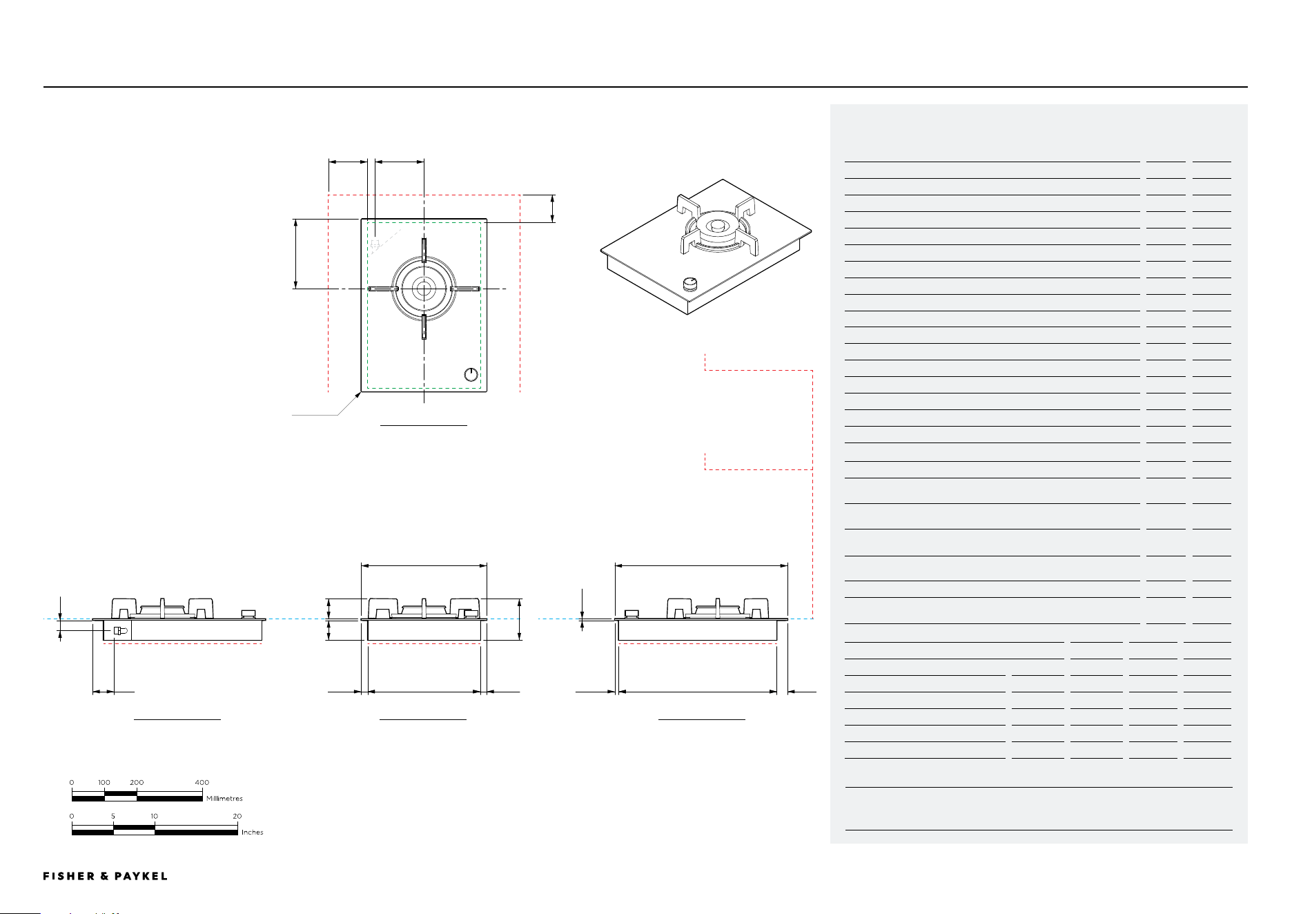
CG151DLPGB5, CG151DNGGB5
Model no:
Gas on Glass Modular Cooktop, 15", LPG - CG151DLPGB5,
Gas on Glass Modular Cooktop, 15", Natural Gas - CG151DNGGB5
Product Dimensions
in
mm
A Overall height of cooktop (including trivet)
5
127
B Overall width of cooktop
15 5/32
385
C Overall depth of cooktop
20 7/8
530
D Height of cooktop glass (includes flange and tape)
1/4
6
E Corner radius of glass
1/16
2
F Height of chassis
2 7/16
61
G Width of chassis
13 9/16
345
H Depth of chassis
19 1/8
485
I Width from side edges of cooktop to chassis
13/16
20
J Depth from front edge of cooktop to chassis
1/2
12
K Depth from back edge of cooktop to chassis
1 5/16
33
L Height of trivet
2 7/16
62
M Distance from centre of burner to rear of cooktop
8 7/16
214
N Height from centre of gas inlet to top of glass
1 1/4
32
O Width from centre of cooktop to gas inlet
5 15/16
150
P Distance from rear of cooktop to gas inlet
2 9/16
65
Product Clearances
in
mm
Q Minimum clearance from side edges of cutout to nearest
combustible surface
4 3/4
120
R Minimum clearance from rear edge of cutout to nearest
combustible surface
3 3/8
85
Minimum clearance from counter top to surface, cabinet or rangehood
directly centered above the cooktop
30
724
Minimum clearance from top of glass surface to overhead cabinet not
directly above cooktop
18
457
Maximum depth of overhead cabinets not directly above cooktop
13
330
Minimum clearance from top of glass surface to top of any appliance,
companion product or obstruction below cooktop
3
76
Cutout Dimensions*
proud in
proud mm
flush in
flush mm
Overall width of cutout
13 11/16
347
13 11/16
347
Overall depth of cutout
19 31/32
507
20 1/32
509
Overall width of recess
-
-
15 5/16
389
Overall depth of recess
-
-
21 1/32
534
Overall height of recess
-
-
1/4
6.5
Recess corner radius
-
-
5/32
4
*Note cutout position is centered to the cooktop.
DATA SHEETS | MODULAR COOKTOPS
n
p
e
m
a
i
F
i
g
l
d
j kh
CLEARANCE: RANGEHOOD,
OVERHEAD CABINET
CLEARANCE: OVERHEAD
CABINET NOT DIRECTLY ABOVE
CLEARANCE: BELOW COOKTOPCLEARANCE: BELOW COOKTOP
DATUM: TOP OF GLASS
CLEARANCE: COMBUSTIBLE SURFACE
CLEARANCE:
COMBUSTIBLE SURFACE
b
15 5/32"
c
20 7/8"
PRoFILE VIEW
FRoNT VIEW
PLAN VIEW
CLEARANCE: BELOW COOKTOP
o
PRoFILE VIEW
q
r
<< CONTENTS
© FISHER & PAYKEL LIMITED 2025 PAGE 1890003312C PLANNING GUIDE MoDULAR CooKToPS VERSIoN C - MAY 2025
INDICATES CABINETRY / PRODUCT DATUM -------------------------
INDICATES CABINETRY CLEARANCES --------------------------------
INDICATES CUTOUT -------------------------------------------------------
IMPORTANT NOTE: Throughout this guide, dimensions may vary by ±2mm (1/16''). Please
read the installation manual for detailed information on installing the product. For full
installation instructions & specifications visit fisherpaykel.com
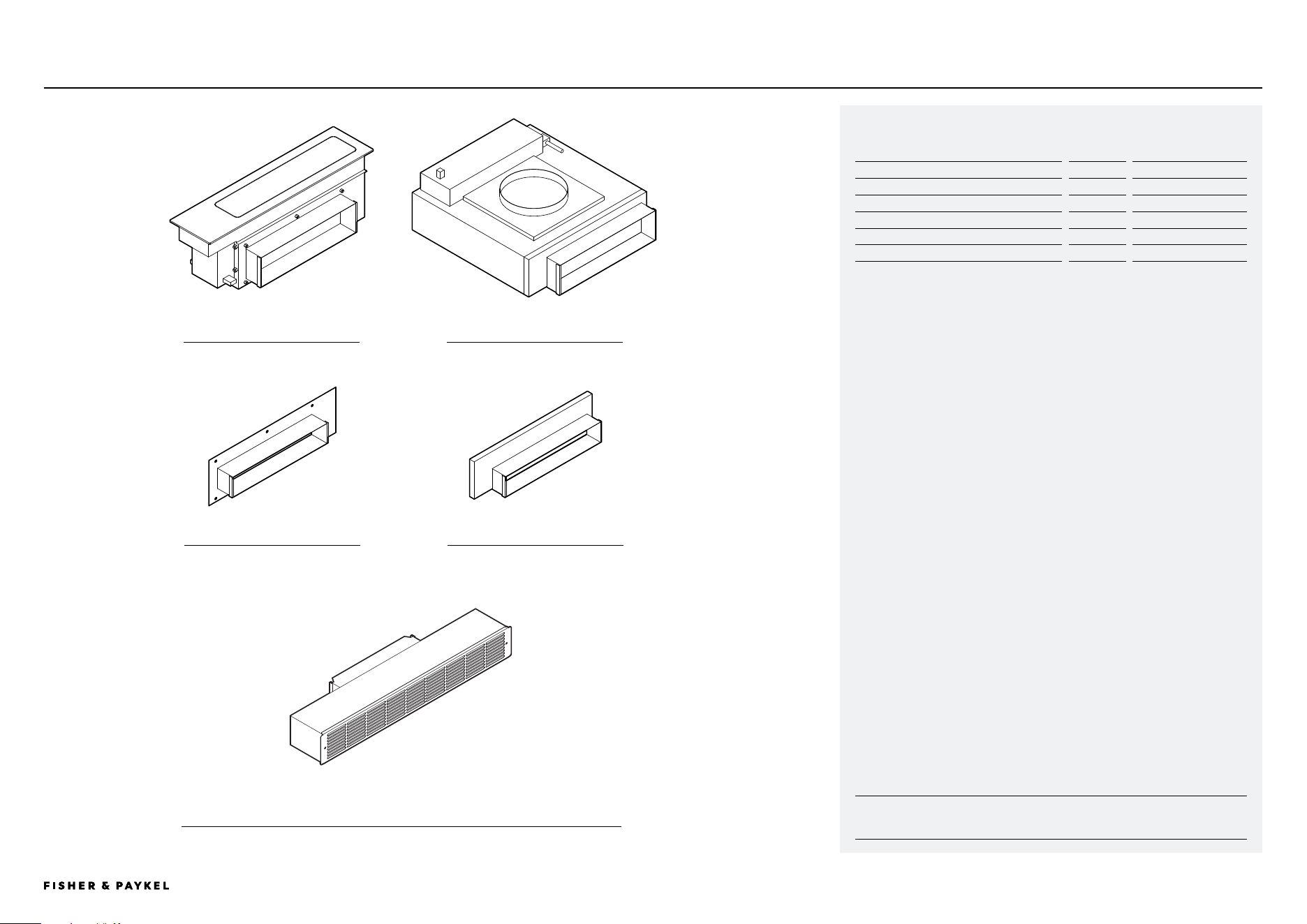
MAINBOX BLOWERBOX
Model no:
Auxiliary Modular Ventilation, 5", Black - DD5DB1
Component Description
Supplied
Optional Accessory
Mainbox
x1
Blowerbox
x1
Mainbox Outlet Adapter, 2.25" x 12"
OAD225X12
Blower Outlet Adapter, 2.25" x 12"
OAB225X12
Recirculation Kit
KRECIRCDDFT
CD5DB1
MAINBOX OUTLET ADAPTER BLOWERBOX OUTLET ADAPTER
DATA SHEETS | MODULAR COOKTOPS
RECIRCULATION KIT
<< CONTENTS
© FISHER & PAYKEL LIMITED 2025 PAGE 1990003312C PLANNING GUIDE MoDULAR CooKToPS VERSIoN C - MAY 2025
INDICATES CABINETRY / PRODUCT DATUM -------------------------
INDICATES CABINETRY CLEARANCES --------------------------------
INDICATES CUTOUT -------------------------------------------------------
IMPORTANT NOTE: Throughout this guide, dimensions may vary by ±2mm (1/16''). Please
read the installation manual for detailed information on installing the product. For full
installation instructions & specifications visit fisherpaykel.com
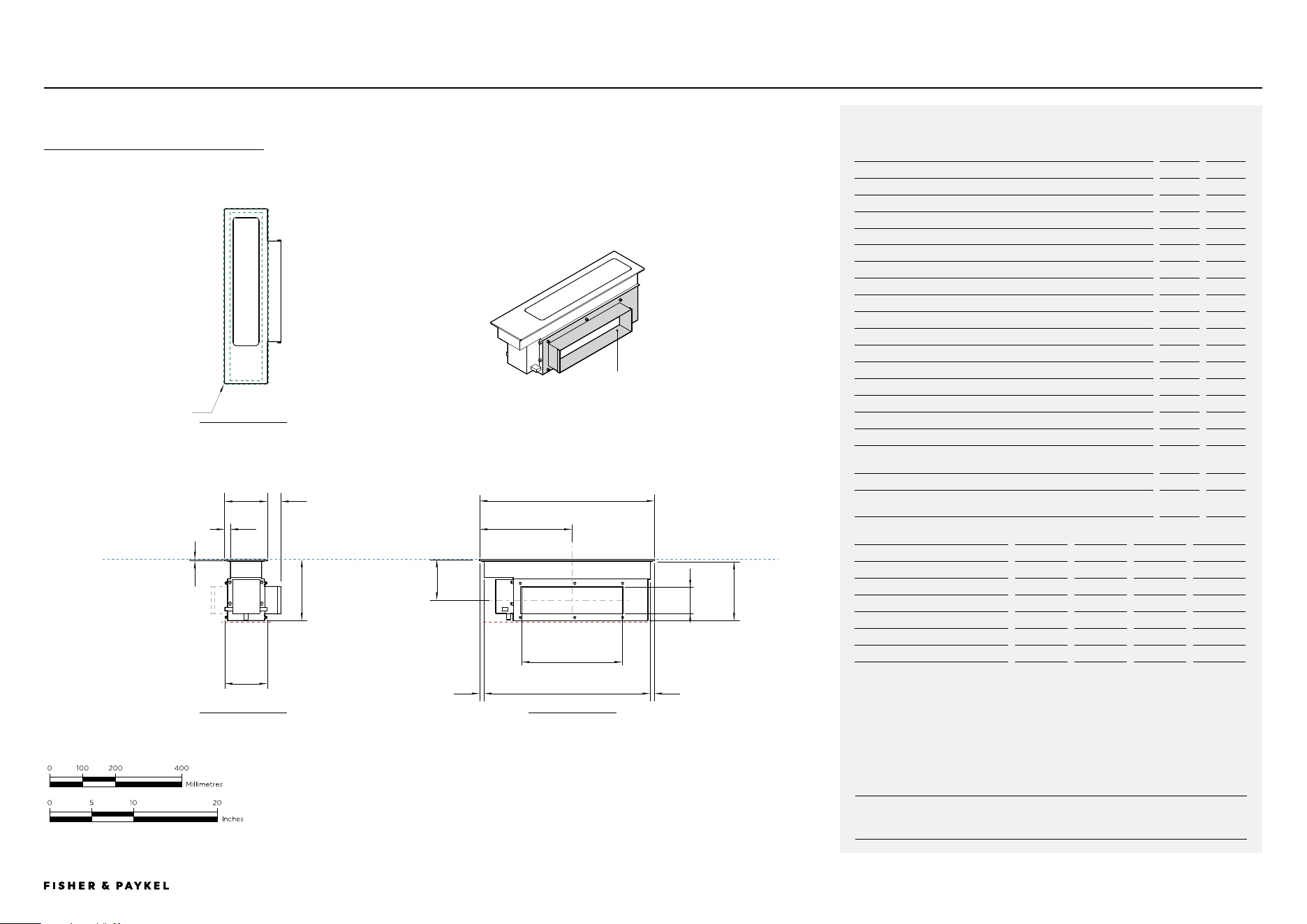
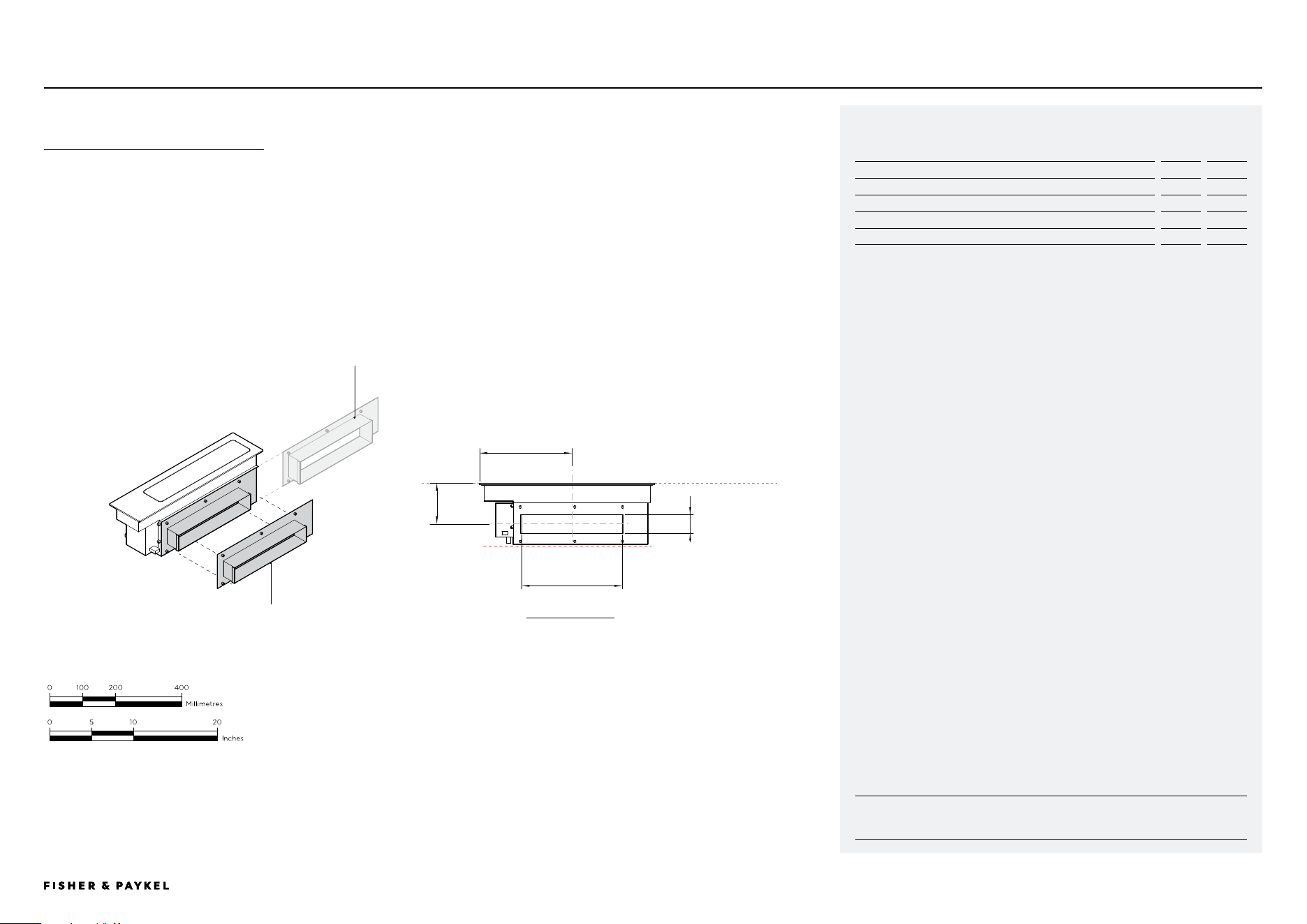
CD5DB1
Model no:
Auxiliary Modular Ventilation, 5", Black - CD5DB1
Product Dimensions
in
mm
A Overall height of mainbox
7 3/8
186
B Overall width of mainbox
5 1/8
130
C Overall depth of mainbox
20 7/8
530
D Height of glass (includes flange and tape)
1/4
6
E Corner radius of glass
1/16
2
F Height of chassis
7 2/16
180
G Width of lower chassis (includes communication ports)
5
126
H Width from sides of glass to neck of chassis
11/16
18
I Depth of chassis
19 7/8
504
J Depth from front edge of glass to chassis
17/32
13.5
K Depth from back edge of glass to chassis
1/2
12.5
L Height from top of glass to center of outlet
4 7/ 8
124
M Depth from front edge of glass to center of outlet
11
280
N Width from edge of glass to outside of outlet
1 5/8
41
O Height of outlet
3 1/4
83
P Width of outlet
12
305
Product Clearances
in
mm
Minimum clearance from top surface to top of any appliances,
companion product or obstruction below mainbox
7 7/ 8
200
Cutout Dimensions*
proud in
proud mm
flush in
flush mm
Overall width of cutout
3 7/ 8
98
3 7/ 8
98
Overall depth of cutout
19 31/32
507
20 1/32
509
Overall width of recess
-
-
5 9/32
134
Overall depth of recess
-
-
21 1/32
534
Overall height of recess
-
-
1/4
6.5
Recess corner radius
-
-
5/32
4
*Note cutout position is centered to the cooktop.
a
b
c
d
e
F
g
h
i
j k
l
m
n
o
p
MAINBOX
AS SUPPLIED
7 5/16"
5 1/8"
DATA SHEETS | MODULAR COOKTOPS
PRoFILE VIEW
FRoNT VIEW
PLAN VIEW
SUPPLIED OUTLET
Suits 3.25" x 12"
metal ducting.
DATUM: TOP OF GLASS
<< CONTENTS
© FISHER & PAYKEL LIMITED 2025 PAGE 2090003312C PLANNING GUIDE MoDULAR CooKToPS VERSIoN C - MAY 2025
INDICATES CABINETRY / PRODUCT DATUM -------------------------
INDICATES CABINETRY CLEARANCES --------------------------------
INDICATES CUTOUT -------------------------------------------------------
IMPORTANT NOTE: Throughout this guide, dimensions may vary by ±2mm (1/16''). Please
read the installation manual for detailed information on installing the product. For full
installation instructions & specifications visit fisherpaykel.com
CD5DB1
r
t
q
s
Model no:
Mainbox Outlet Adapter, 2.25" x 12" - OAD225X12
Product Dimensions
in
mm
Q Height from top of glass to center of outlet
4 7/ 8
124
R Depth from front edge of mainbox glass to center of outlet
11
280
S External height of outlet
2 1/4
57
T External width of outlet
12
305
MAINBOX
WITH MAINBOX OUTLET ADAPTER
MAINBOX OUTLET ADAPTER
Fixed directly to Mainbox.
Suits 2.25" x 12" metal ducting.
SUPPLIED OUTLET
Removed to allow fitting
of outlet adapter.
DATA SHEETS | MODULAR COOKTOPS
PRoFILE VIEW
<< CONTENTS
© FISHER & PAYKEL LIMITED 2025 PAGE 2190003312C PLANNING GUIDE MoDULAR CooKToPS VERSIoN C - MAY 2025
INDICATES CABINETRY / PRODUCT DATUM -------------------------
INDICATES CABINETRY CLEARANCES --------------------------------
INDICATES CUTOUT -------------------------------------------------------
IMPORTANT NOTE: Throughout this guide, dimensions may vary by ±2mm (1/16''). Please
read the installation manual for detailed information on installing the product. For full
installation instructions & specifications visit fisherpaykel.com
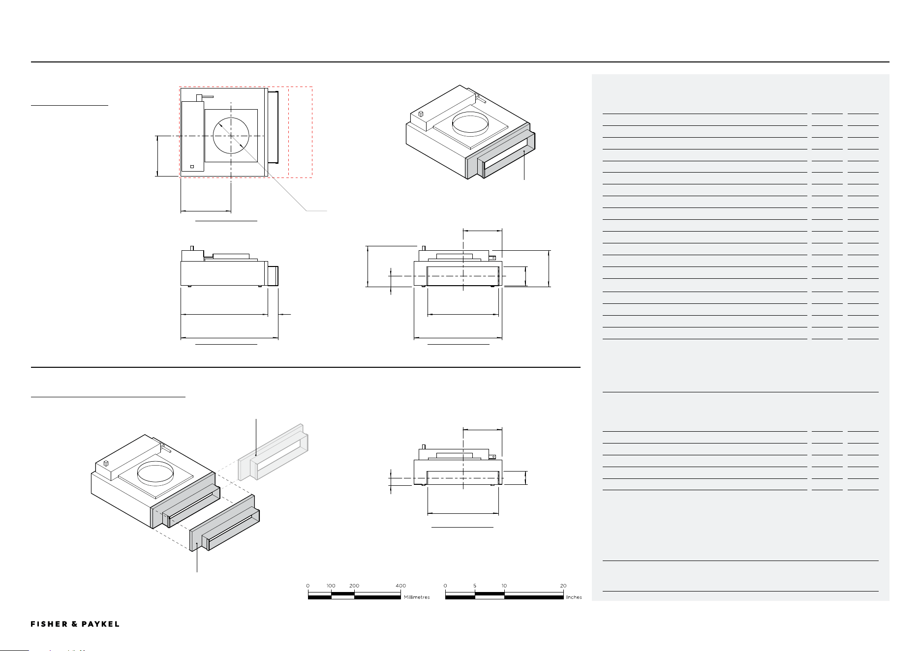
CD5DB1
Model no:
Auxiliary Modular Ventilation, 5", Black - CD5DB1
Product Dimensions
in
mm
A Overall height of blowerbox
6 15/16
175
B Overall width of blowerbox (including outlet)
16 1/2
419
C Overall depth of blowerbox
14 15/16
379
D Width of blowerbox chassis
14 13/16
375
E Width from corner to center of inlet
8 9/16
217
F Depth from corner to center of inlet
6 7/ 8
175
G Internal diameter of inlet
6 1/16
154
H Height from base of mainbox to center of outlet
1 5/16
33
I Width from outside of chassis to center of outlet
6 11/16
169
J Height of outlet
3 1/4
83
K Width of outlet
12
305
L Depth of outlet
1 3/4
44
M Height of blowerbox (excluding communications connector)
6 3/16
156
Cutout Dimensions*
in
mm
Recommended width of cutout **
22 7/16
570
Minimum width of cutout ***
18 1/2
470
Depth of cutout
15 3/8
390
*Blowerbox can be rotated to achieve desired outlet direction, cutout dimensions must be similarly rotated.
** Recommended width allows greater access to outlet for connecting ducting during installation.
*** Clearance only for blowerbox, does not provide allowances for connecting to ducting within kickstrip
BLOWERBOX
WITH BLOWER OUTLET ADAPTER
BLOWERBOX
AS SUPPLIED
OUTLET ADAPTER, BLOWER
Fixed directly to Blowerbox.
Suits 2.25" x 12" metal ducting.
SUPPLIED OUTLET
Removed to allow fitting
of outlet adaptor
A
B C
D
E
F
G
H
i
j
kl
Model no:
Blower Outlet Adapter, 2.25" x 12" - OAB225X12
Product Dimensions
in
mm
N Height from base of blowerbox to center of outlet
1 13/16
45
O Width from side of blowerbox chassis to center of outlet
6 11/16
169
P External height of outlet
2 1/4
57
Q External width of outlet
12
305
n
o
p
q
m
DATA SHEETS | MODULAR COOKTOPS
PRoFILE VIEW
FRoNT VIEW
PLAN VIEW
PRoFILE VIEW
SUPPLIED OUTLET
Suits 3.25" x 12" metal
ducting.
<< CONTENTS
© FISHER & PAYKEL LIMITED 2025 PAGE 2290003312C PLANNING GUIDE MoDULAR CooKToPS VERSIoN C - MAY 2025
INDICATES CABINETRY / PRODUCT DATUM -------------------------
INDICATES CABINETRY CLEARANCES --------------------------------
INDICATES CUTOUT -------------------------------------------------------
IMPORTANT NOTE: Throughout this guide, dimensions may vary by ±2mm (1/16''). Please
read the installation manual for detailed information on installing the product. For full
installation instructions & specifications visit fisherpaykel.com
RECIRCUL ATION KITDATA SHEETS | MODULAR COOKTOPS
Filter Box
Carbon Filter Downdraft FP US
Included, available as spare part FILTCARDDFT
Grille, brushed stainless steel
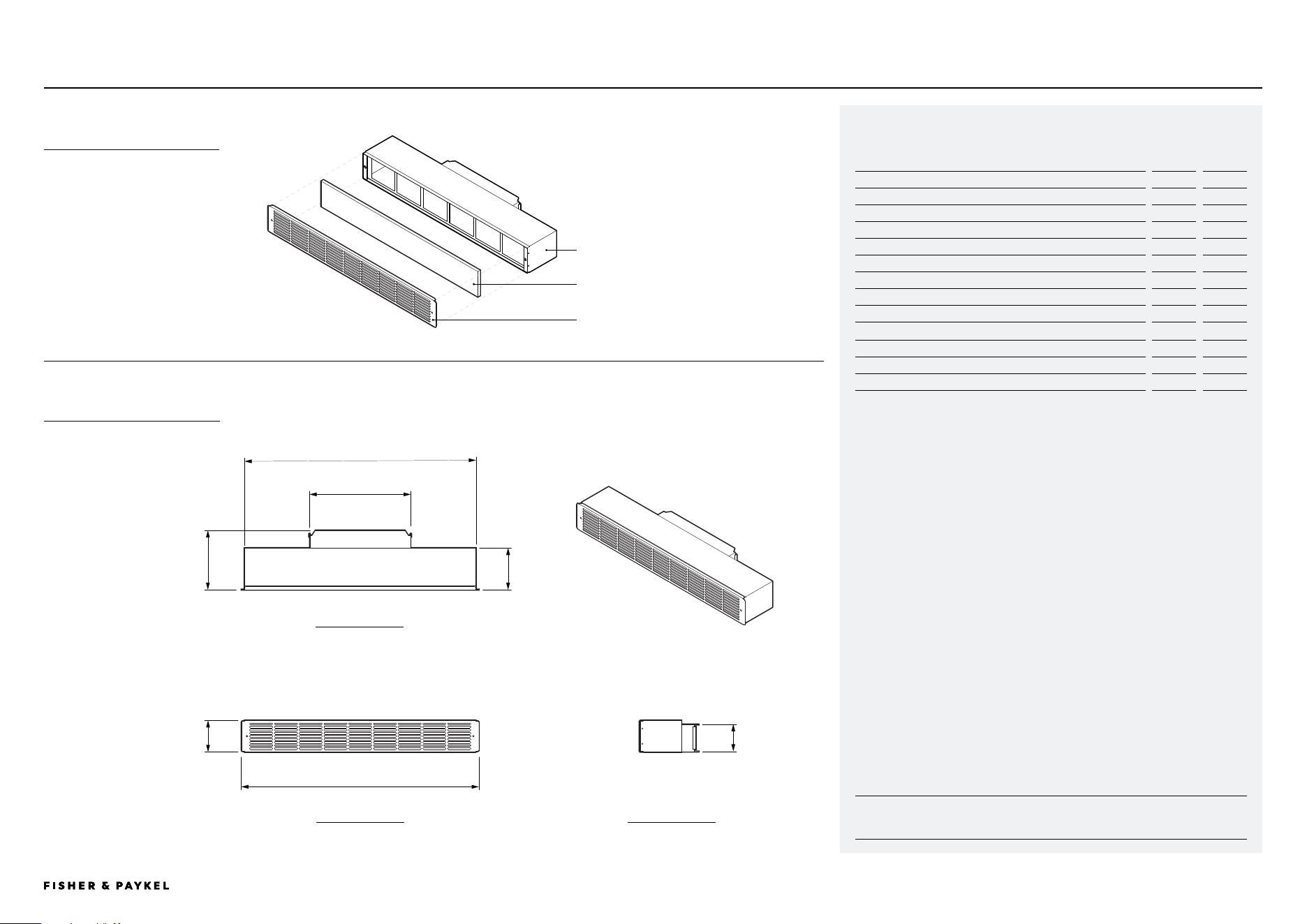
Model no:
Recirculation Kit - KRECIRCDDFT
Overall assembly
Product Dimensions
in
mm
A Overall height of recirculation kit
3 13/16
96
B Overall width of recirculation kit
28 3/8
720
C Overall depth of recirculation kit
7 1/8
180
D Width of filter box chassis
27 11/16
702
E Depth of filter box chassis and front grille
5
127
F Height of outlet
3 1/4
83
G Width of outlet
12
305
Cutout Dimensions
in
mm
Recommended width of cutout
27 3/4
705
Minimum width of cutout
3 7/ 8
99
RECIRCULATION KIT
COMPONENT OVERVIEW
RECIRCULATION KIT
OVERALL ASSEMBLY
B
a
g
f
c
PRoFILE VIEWFRoNT VIEW
PLAN VIEW
e
d
<< CONTENTS
© FISHER & PAYKEL LIMITED 2025 PAGE 2390003312C PLANNING GUIDE MoDULAR CooKToPS VERSIoN C - MAY 2025
INDICATES CABINETRY / PRODUCT DATUM -------------------------
INDICATES CABINETRY CLEARANCES --------------------------------
INDICATES CUTOUT -------------------------------------------------------
IMPORTANT NOTE: Throughout this guide, dimensions may vary by ±2mm (1/16''). Please
read the installation manual for detailed information on installing the product. For full
installation instructions & specifications visit fisherpaykel.com
RECIRCUL ATION KIT
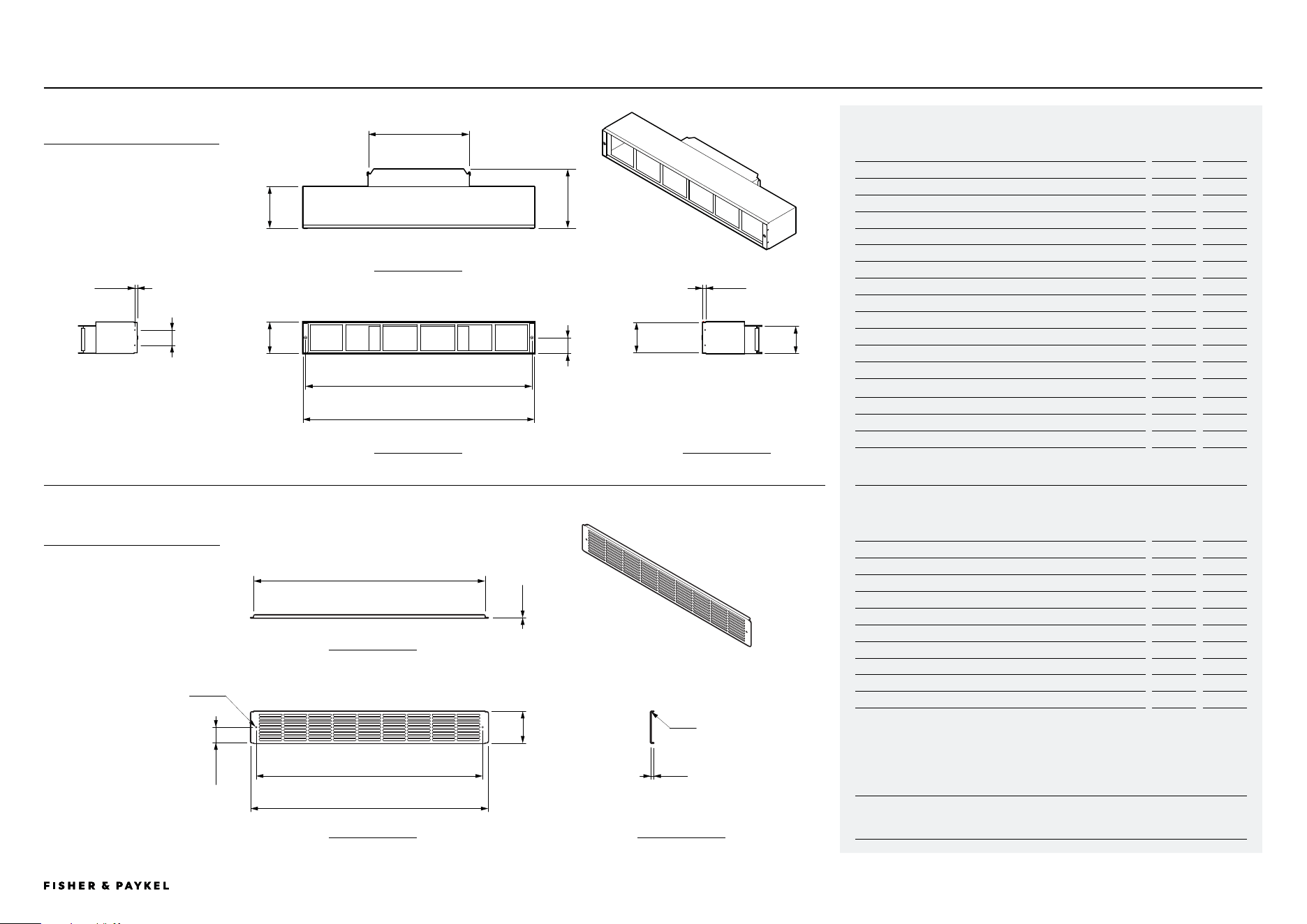
Model no:
Filter Box, Recirculation Kit
Product Dimensions
in
mm
A Overall height of filter box
3 13/16
96
B Overall width of filter box
27 5/8
702
C Overall depth of filter box
7 1/16
179
D Depth of filter box chassis (includes nutsert)
5
126
E Height of chassis step down for grille
3 5/8
92
F Depth of chassis step down for grille
7/ 1 6
11
G Width between grille fastening holes
27 1/32
686.5
H Height of grille fastening holes from base of chassis
1 7/ 8
48
I Height of outlet
3 1/4
83
J Width of outlet
12
305
K Height between centre of holes (central to chassis)
1 13/16
46
L Centre of holes to front of chassis (includes nutsert)
1/4
5/16
Cutout Dimensions
in
mm
Recommended width of cutout
27 3/4
705
Minimum width of cutout
3 7/ 8
99
Model no:
Grille, Recirculation Kit
Product Dimensions
in
mm
A Overall height of grille
3 13/16
96
B Overall width of grille
28 3/8
720
C Overall depth of grille
3/8
10
D Width of flange
27 5/8
701
E Thickness of sheet metal
1/16
1
F Internal radius of bend
1/32
0.5
G Height from base of grille to centre of holes
1 7/ 8
47.5
H Width between centre of holes
27 1/32
686.5
I Diameter of holes
7/ 3 2
5.5
DATA SHEETS | MODULAR COOKTOPS
PRoFILE VIEW
FRoNT VIEW
PLAN VIEW
C
B
A
e
g
d
f
j
i
RECIRCULATION KIT
FILTER BOX
RECIRCULATION KIT
GRILLE
h
A
h
g
b
d
i
e
c
PRoFILE VIEW
FRoNT VIEW
PLAN VIEW
f
K
L
<< CONTENTS

© FISHER & PAYKEL LIMITED 2025 PAGE 2490003312C PLANNING GUIDE MoDULAR CooKToPS - VERSIoN C - MAY 2025
PRODUCT DECISIONS
<< CONTENTS
© FISHER & PAYKEL LIMITED 2025 PAGE 2590003312C PLANNING GUIDE MoDULAR CooKToPS VERSIoN C - MAY 2025
The models shown in this Planning Guide may not be available in all markets and are subject to change at any time. Product specifications may vary from those shown. This Planning Guide should not be used as installation guidance for any product. Further information is required to safely and correctly install the
products featured here. Specific installation guidance will be available with the product on delivery and on our website fisherpaykel.com
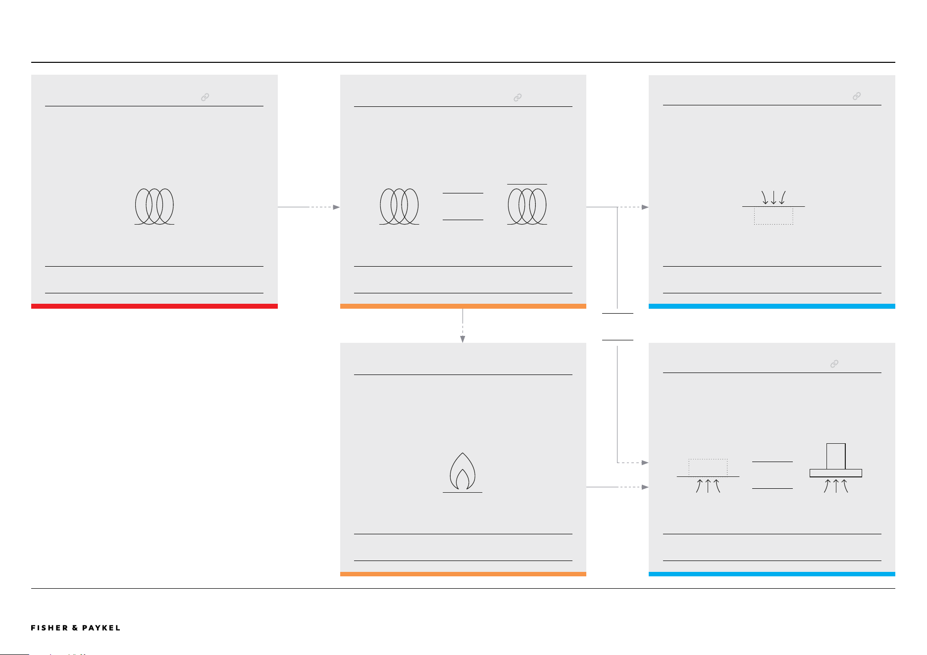
MODULAR SYSTEM CAPABILITIES
PRIMARY COOKTOP
Touchscreen user interface.
Paired with and controls auxiliary modules and overhead
ventilation units.
Available in 15", 24" 30" 36" widths.
INDUCTION
ESSENTIAL
1x MAXIMUM
PRODUCT DECISIONS | MODULAR COOKTOPS
GAS ON GLASS MODULAR COOKTOP
Independant control dial. Unable to be paired. Installation
compatible with primary and auxiliary cooktops.
Can not be used with Auxiliary Modular Ventilation.
Available in 15" widths.
OPTIONAL
0+
GAS
AUXILIARY COOKTOP
No user interface. Must be paired with and controlled via
the primary cooktop.
Available in 12" and 15" widths.
INDUCTION TEPPANYAKI
MIX AND
MATCH
OPTIONAL
0-2x
AUXILIARY MODULAR VENTILATION
No user interface. Must be paired with and controlled via
the primary cooktop.
Up to two modules can be paired, quantity dependant on
number and size of cooktop modules.
DOWNDRAFT
RECOMMENDED
1-2x
INSERT
RECOMMENDED
1x
OVERHEAD VENTILATION
A single rangehood can be paired with and controlled via
the primary cooktop.
Insert rangehoods available in 24", 30" and 36" widths.
Wall rangehoods available 30" and 36" widths.
WALL
EITHER
OR
OR
<< CONTENTS
© FISHER & PAYKEL LIMITED 2025 PAGE 2690003312C PLANNING GUIDE MoDULAR CooKToPS VERSIoN C - MAY 2025
The models shown in this Planning Guide may not be available in all markets and are subject to change at any time. Product specifications may vary from those shown. This Planning Guide should not be used as installation guidance for any product. Further information is required to safely and correctly install the
products featured here. Specific installation guidance will be available with the product on delivery and on our website fisherpaykel.com
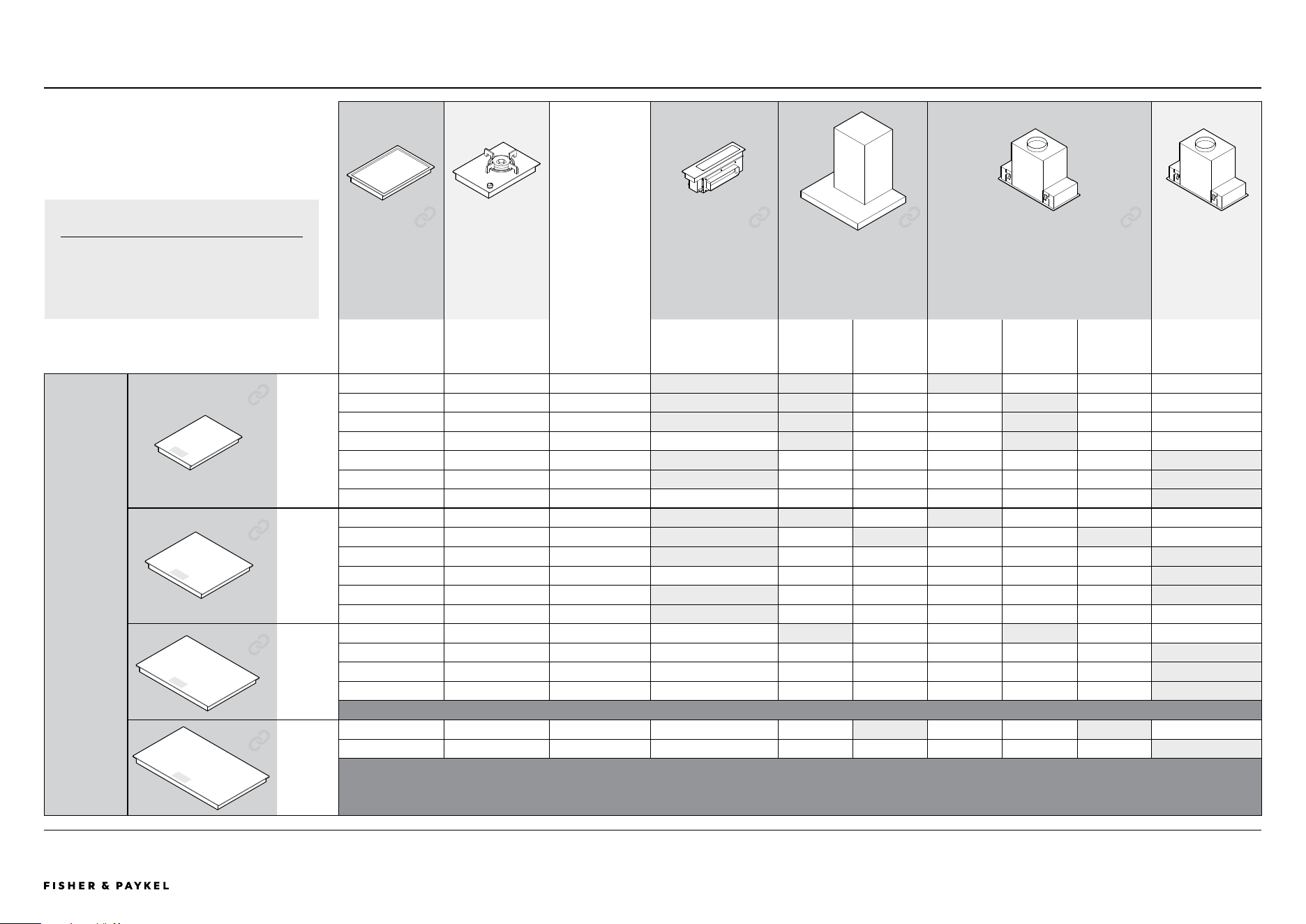
Primary cooktops have a touchscreen via which the Auxiliary Induction,
Teppanyaki and Ventilation modules are controlled. Gas on Glass modules are
independantly controlled and can not be paired with a Primary module.
Mix and match up to 2x Auxiliary cooktops and multiple Gas on Glass modules. Ventilation options are dependant on module sizes, pairings and cook type.
Overhead ventilation can be used for all cook types while Modular downdraft
ventilation can only be installed with with Induction and Teppanyaki modules
and never with Gas on Glass.
PRIMARY MODULAR COOKTOPS - CONNECTED GAS ON GLASS MODULAR COOKTOPS AUXILIARY MODULAR VENTILATION - CONNECTED
Primary Modular Induction Cooktop, 15" CI152DTTB1 Gas on Glass Modular Cooktop, 15", LPG CG151DLPGB5 Auxiliary Modular Ventilation, 5" CD5DB1
Primary Modular Induction Cooktop, 24" CI244DTTB1 Gas on Glass Modular Cooktop, 15", Natural Gas CG151DNGGB5
Primary Modular Induction Cooktop, 30" CI304DTTB1 OVERHEAD VENTILATION - CONNECTED
Primary Modular Induction Cooktop, 36" CI365DTTB1 AUXILIARY MODULAR COOKTOPS - CONNECTED Wall Range Hood, 30", Box Chimney HC30DCXB4
Auxiliary Modular Induction Cooktop, 12" CI122DB1 Wall Range Hood, 36" Box Chimney HC36DCXB4
Auxiliary Modular Induction Cooktop, 15" CI152DB1 Integrated Insert Range Hood, 24" HP24IDCHX4
Auxiliary Modular Teppanyaki Cooktop, 12" CIT122DX1 Integrated Insert Range Hood, 30" HP30IDCHX4
Auxiliary Modular Teppanyaki Cooktop, 15" CIT152DX1 Integrated Insert Range hood, 36" HP36IDCHX4
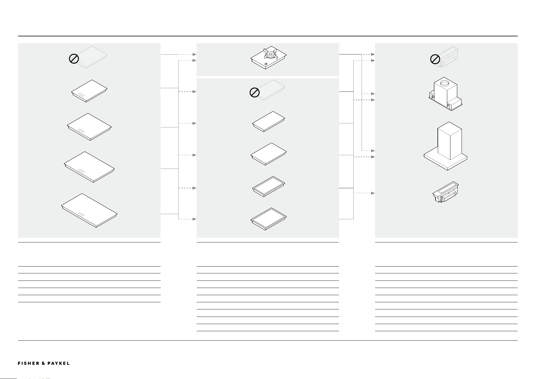
MODULAR SYSTEM PRODUCT OPTIONS
Primary Modular Induction Cooktop, 15"
Primary Modular Induction Cooktop, 24"
Primary Modular Induction Cooktop, 36"
NO Primary Modular Cooktop
NO Auxiliary Modular Cooktop
Auxiliary Modular Teppanyaki Cooktop, 15"
NO Auxiliary Modular Ventilation
Primary Modular Induction Cooktop, 30"
Auxiliary Modular Induction Cooktop, 12"
Auxiliary Modular Induction Cooktop, 15"
Auxiliary Modular Teppanyaki Cooktop, 12"
Gas on Glass Modular Cooktop, 15"
Insert Rangehood
Wall Rangehood
Auxiliary Modular Ventilation
PRODUCT DECISIONS | MODULAR COOKTOPS
<< CONTENTS
© FISHER & PAYKEL LIMITED 2025 PAGE 2790003312C PLANNING GUIDE MoDULAR CooKToPS VERSIoN C - MAY 2025
The models shown in this Planning Guide may not be available in all markets and are subject to change at any time. Product specifications may vary from those shown. This Planning Guide should not be used as installation guidance for any product. Further information is required to safely and correctly install the
products featured here. Specific installation guidance will be available with the product on delivery and on our website fisherpaykel.com
PAIRING GUIDEPRODUCT DECISIONS | MODULAR COOKTOPS
AUXILIARY
COOKTOP
GASS ON GLASS
COOKTOP
COMBINED
COOKTOP WIDTH
AUXILIARY MODULAR
VENTILATION
WALL RANGEHOOD INSERT RANGEHOOD INSERT RANGEHOOD
CONNECTED NOT connected CONNECTED CONNECTED CONNECTED NOT connected
x0-2 x0-2 x1-2 x1 x1 x1
CI122D
CIT122DX1
CI152D
CIT152DX1
CG151DLPGB5
CG151DNGGB5
Width of cooktop(s)
must be equal to
or smaller than
rangehood width
DOWNDRAFT
CD5D
30"
HC30DCXB4
36"
HC36DCXB4
24"
HP24IDCHX4
30"
HP30IDCHX4
36"
HP36IDCHX4
48"
HPB4819-12
PRIMARY
COOKTOP
CONNECTED
X1
15" x1 x1 x1
15"
CI152DTT
x1 12" 27" x1 x1 x1
x1 15" 30" x1 x1 x1
x1 15" 30" x1 x1
x2 12" 39" x2 x1
x2 15" 45" x2 x1
x1 15" x1 15" 45" x1
24" x2 x1 x1
24"
CI244DTT
x1 12" 36" x2 x1 x1
x1 15" 39" x2 x1
x1 15" 39" x1
x2 12" 48" x2 x1
x2 15" 54" x2
30" x1 x1
30"
CI304DTT
x1 12" 42" x1
x1 15" 45" x1
x1 15" 45" x1
Wider cooktop combinations are not able to be vented by modular ventilation or a single overhead unit.
36" x1 x1
36"
CI365DTT
x1 12" 48" x1
Wider cooktop combinations are not able to be vented by modular ventilation or a single overhead unit.
PLEASE NOTE
Alternative non-connected rangehood width
and styles are available.
<< CONTENTS
© FISHER & PAYKEL LIMITED 2025 PAGE 2890003312C PLANNING GUIDE MoDULAR CooKToPS VERSIoN C - MAY 2025
The models shown in this Planning Guide may not be available in all markets and are subject to change at any time. Product specifications may vary from those shown. This Planning Guide should not be used as installation guidance for any product. Further information is required to safely and correctly install the
products featured here. Specific installation guidance will be available with the product on delivery and on our website fisherpaykel.com
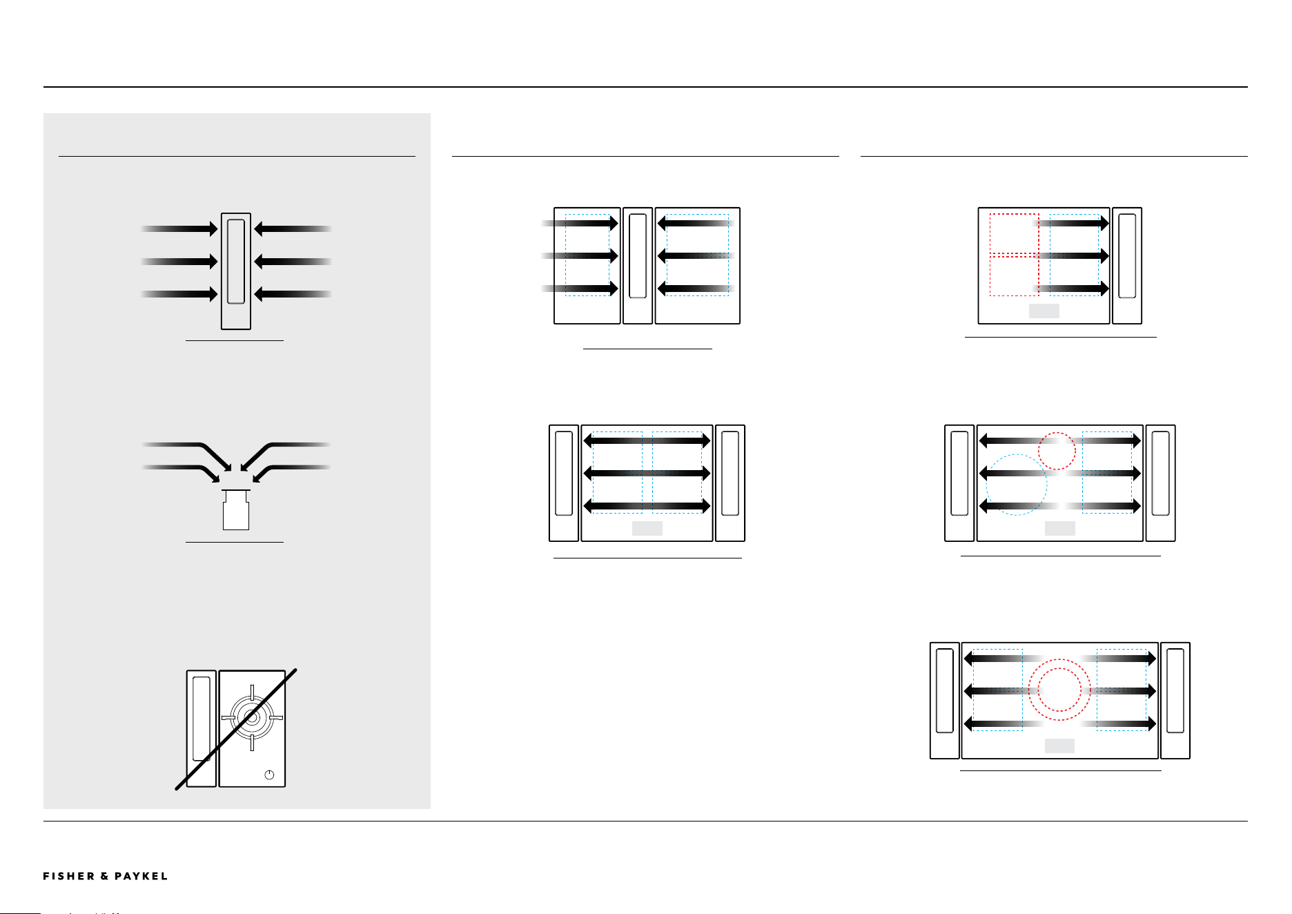
DOWNDRAFT VENTILATION
The modular ventilation unit is a downdraft ventilation system that
efficiently extracts air across and downwards.
The modular ventilation unit provides efficient ventilation to
adjacent cook zones. Consideration of cook zone layout and cook
module size is critical for optimum pairing of ventilation type and
quantity.
Important: Where modular ventilation is unable to provide efficient
venting it is recommended that overhead extraction is chosen.
WARNING:
Modular Ventilation cannot be used alongside a gas cooktop.
MODULAR VENTILATION CAPABILITIES
SUFFICIENT VENTILATION
ADJACENT COOK ZONES ARE EFFECTIVELY VENTED
INSUFFICIENT VENTILATION
NON-ADJACENT COOK ZONES ARE NOT SUFFICIENTLY VENTED
12" & 15" MoDULES
24" PRIMARY MoDULE WITH 2X DoWNDRAFT
24" PRIMARY MoDULE WITH 1X DoWNDRAFT
30" PRIMARY MoDULE WITH 2X DoWNDRAFT
36" PRIMARY MoDULE WITH 2X DoWNDRAFT
ToP VIEW
FRoNT VIEW
!
PRODUCT DECISIONS | MODULAR COOKTOPS
<< CONTENTS

© FISHER & PAYKEL LIMITED 2025 PAGE 2990003312C PLANNING GUIDE MoDULAR CooKToPS - VERSIoN C - MAY 2025
PLANNING CONSIDERATIONS
<< CONTENTS
© FISHER & PAYKEL LIMITED 2025 PAGE 3090003312C PLANNING GUIDE MoDULAR CooKToPS VERSIoN C - MAY 2025
The models shown in this Planning Guide may not be available in all markets and are subject to change at any time. Product specifications may vary from those shown. This Planning Guide should not be used as installation guidance for any product. Further information is required to safely and correctly install the
products featured here. Specific installation guidance will be available with the product on delivery and on our website fisherpaykel.com
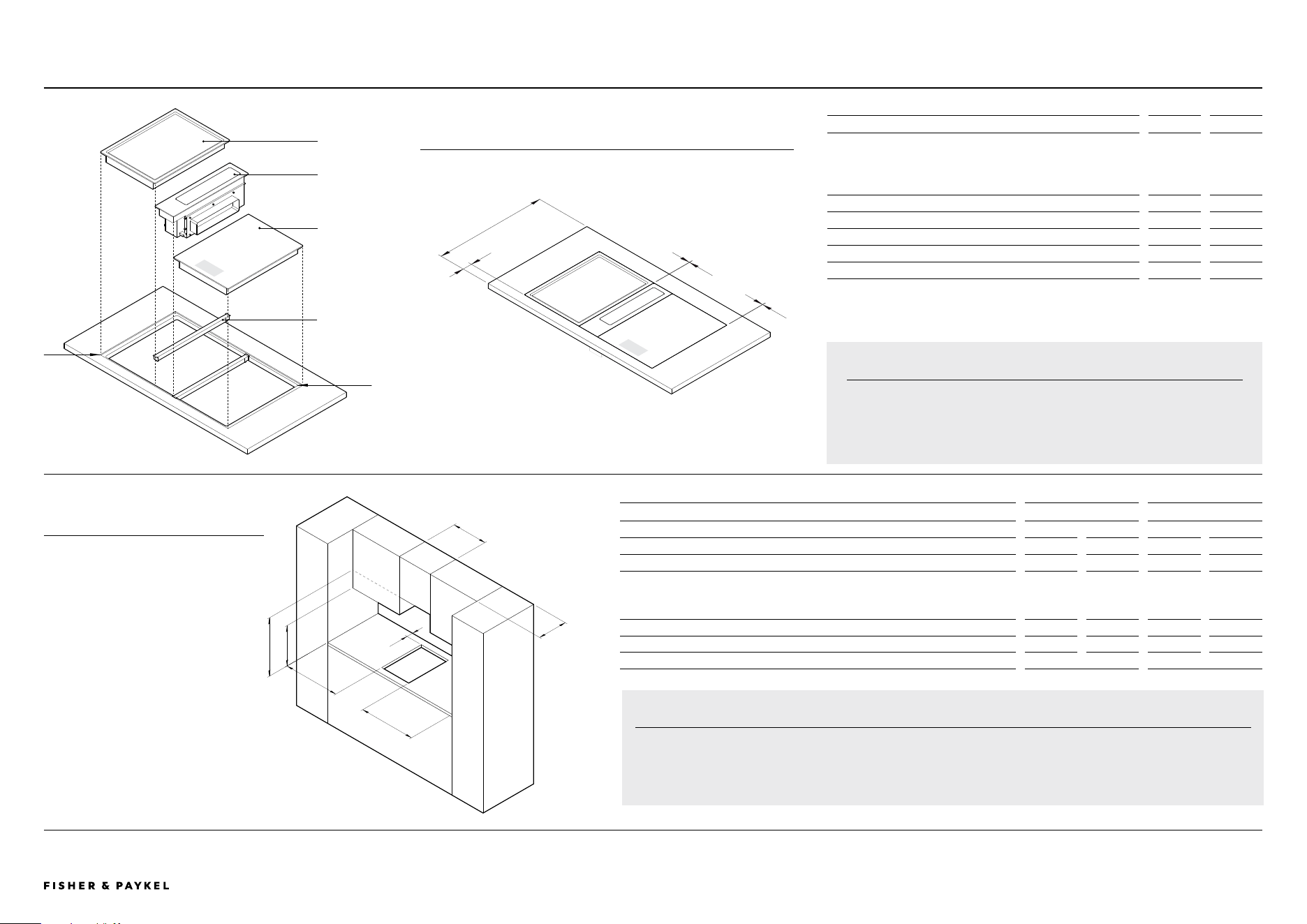
COUNTERTOP DIMENSIONS in mm
A Minimum countertop depth*
- Induction and teppanyaki
- with gas on glass cooktop
- with auxiliary ventilation, ducting routed below cooktops **
- with auxiliary ventilation, ducting routed to rear of cabinet **
23 5/8
26 3/16
23 5/8
27 9/16
600
665
600
700
B Nominal distance from front of countertop to front of cooktop 2 3/8 60
C Distance between modules 5/64 2
D Distance between edge of module and edge of recess 5/64 2
E Corner radii of cutout ** max 3/8 max 10
F Corner radii of recess ** 5/32 4
* Based on nominal distance 'B'. Does not allow for ducting. Dependant on countertop materials.
** Guideline only, based on generic metal ducting. Customer must supply ducting and calculate cabinetry and countertop
dimensions specific to chosen duct type and layout.
INSTALLATION OVERVIEW
a
B
C
D
E
F
JOINER BAR
Required between
modules, supplied
with auxiliary
modules.
PRIMARY
COOKTOP
AUXILIARY
VENTILATION
AUXILIARY
COOKTOP
IMPORTANT NOTE
Cutout widths and radii may not be possible in certain countertop
materials. Please refer to countertop suppliers material specifications and
fabrication parameters.
PLANNING CONSIDERATIONS | MODULAR COOKTOPS
g
g
h
i j
k
CABINETRY CLEARANCE DIMENSIONS Induction & Tepanyaki Gas on Glass
in mm in mm
G Minimum clearance from side edges of cutout to nearest combustible surface
1 3/16
29
4 3/4
120
H Minimum clearance from rear edge of cutout to nearest combustible surface 7/ 8
21
3 3/8
85
I Minimum clearance from countertop to:
Overhead cabinet centered above the cooktop (unprotected)
Overhead cabinet centered above the cooktop (protected)
Range hood
24
610
30
724
J Minimum clearance from countertop to overhead cabinet not directly above cooktop
18
457
18
457
K Maximum depth of overhead cabinetry 13 330 13 330
L Minimum distance between overhead cabinets (not centered above cooktop) combined cooktop width combined cooktop width
IMPORTANT NOTE
Gas on Glass modules have greater clearance requirements compared to Induction and Tepanyaki modules. For
multiproduct installations ensure clearances are achieved for the product with the greater clearance requirements.
l
INSTALLATION OVERVIEW
CLEARANCE OVERVIEW
<< CONTENTS
© FISHER & PAYKEL LIMITED 2025 PAGE 3190003312C PLANNING GUIDE MoDULAR CooKToPS VERSIoN C - MAY 2025
The models shown in this Planning Guide may not be available in all markets and are subject to change at any time. Product specifications may vary from those shown. This Planning Guide should not be used as installation guidance for any product. Further information is required to safely and correctly install the
products featured here. Specific installation guidance will be available with the product on delivery and on our website fisherpaykel.com
COMBINED INSTALLATION OVERVIEW
A
E
D
C
B
F
B
A
OVERALL WIDTH OF MODULES = COMBINED PRODUCT WIDTHS
add module widths
+ GAPS BETWEEN MODULES
5/32" (2mm) x
(number of modules -1)
B
WIDTH OF CUTOUT
FLUSH AND PROUD
= OVERALL WIDTH OF MODULES - LEFT OVERHANG
3/4" (19mm) Induction /
Teppanyaki / Gas OR
5/8" (16mm) Downdraft
- RIGHT OVERHANG
3/4" (19mm) Induction /
Teppanyaki / Gas OR
5/8" (16mm) Downdraft
C
DEPTH OF CUTOUT
PROUD
= 19 31/32"
(507mm)
B
WIDTH OF CUTOUT
FLUSH AND PROUD
= OVERALL WIDTH OF MODULES - LEFT OVERHANG
3/4" (19mm) Induction /
Teppanyaki / Gas OR
5/8" (16mm) Downdraft
- RIGHT OVERHANG
3/4" (19mm) Induction /
Teppanyaki / Gas OR
5/8" (16mm) Downdraft
D
DEPTH OF CUTOUT
FLUSH
= 20 1/32"
(509mm)
E
WIDTH OF RECESS
FLUSH
= OVERALL WIDTH OF MODULES + 5/32" (4mm)
5/32" (2mm) each side
F
DEPTH OF RECESS
FLUSH
= 21 1/32"
(534mm)
= 20 7/8" (530mm)
product depth
+ 5/32" (4mm)
5/32" (2mm) top and bottom
COMBINED COUNTERTOP EQUATIONS
Pairings of modular products have been designed to fit in a singular countertop cutout. When grouping modules it is essential to calculate
their combined cutout requirements. The following equations can be used to guide calculations.
For dimensions of common configurations please refer to subsequent pages.
FLUSH PROUD MODULES
PLANNING CONSIDERATIONS | MODULAR COOKTOPS
<< CONTENTS
© FISHER & PAYKEL LIMITED 2025 PAGE 3290003312C PLANNING GUIDE MoDULAR CooKToPS VERSIoN C - MAY 2025
The models shown in this Planning Guide may not be available in all markets and are subject to change at any time. Product specifications may vary from those shown. This Planning Guide should not be used as installation guidance for any product. Further information is required to safely and correctly install the
products featured here. Specific installation guidance will be available with the product on delivery and on our website fisherpaykel.com
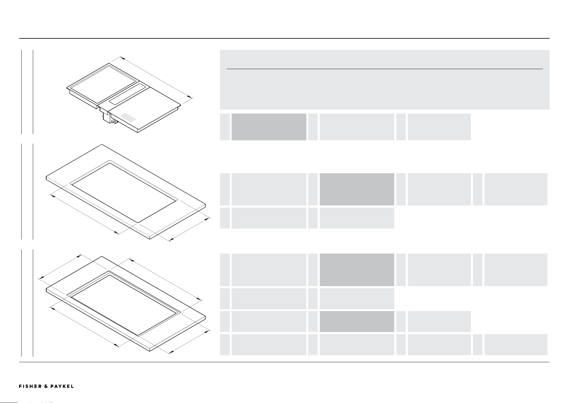
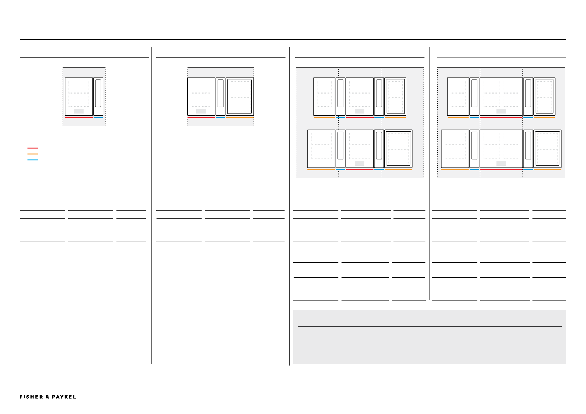
TYPICAL CONFIGURATIONS WITH MODULAR VENTILATION
5 THREE IN A ROW WITH MODULAR VENTILATION - 24+12+12
Dimensions WxDxH
in
mm
Combined Module Size
57 13/16 x 20 7/8 x 7 1/16
1468 x 530 x 180
Proud cutout
56 5/16 x 19 31/32
1430 x 507
Flush cutout
56 5/16 x 20 1/16
1430 x 509
Flush recess
57 31/32 x 21 1/32 x 1/4
1472 x 534 x 6.5
6 THREE IN A ROW WITH MODULAR VENTILATION - 60+15+15
Dimensions WxDxH
in
mm
Combined Module Size
64 1/2 x 20 7/8 x 7 1/16
1638 x 530 x 180
Proud cutout
63 x 19 31/32
1600 x 507
Flush cutout
63 x 20 1/16
1600 x 509
Flush recess
1642.3 x 21 1/32 x 1/4
1642 x 534 x 6.5
1 SINGLE WITH MODULAR VENTILATION - 15
Dimensions WxDxH
in
mm
Combined Module Size
20 3/8 x 20 7/8 x 7 1/16
517 x 530 x 180
Proud cutout*
19 x 19 31/32
482 x 507
Flush cutout*
19 x 20 1/16
482 x 509
Flush recess
20 17/32 x 21 1/32 x 1/4
521 x 534 x 6.5
*Cutout width not central to overall width of modules. Oset
specific to placement of downdraft unit to the left or right. Side
overhangs dier for downdraft and cooktop - downdraft 5/8"
(16mm), cooktops 3/4" (19mm). Refer 'Countertop Installation
Details' for more information.
2 TWO IN A ROW WITH MODULAR VENTILATION - 15+15
Dimensions WxDxH
in
mm
Combined Module Size
35 5/8 x 20 7/8 x 7 1/16
904 x 530 x 180
Proud cutout*
33 15/16 x 19 31/32
862 x 507
Flush cutout*
33 15/16 x 20 1/16
862 x 509
Flush recess
35 3/4 x 21 1/32 x 1/4
908 x 534 x 6.5
*Glass overhang at sides adjusted to fit 35 7/16" (900mm) cabinet
constructed from 3/4" (19mm) panels. 34 1/8" (866mm) width
cutout recommended if cabinetry construction allows.
1
24"
15"
SINGLE - COMPACT < 24"
TWO IN A ROW - MID 36"
THREE IN A ROW - EXTRA WIDE > 57"
IMPORTANT NOTE
Other configurations are possible.
Cutout widths may not be possible in certain countertop materials. Please refer to countertop suppliers
recommendations for material parameters and fabrication recommendations.
3 THREE IN A ROW WITH MODULAR VENTILATION - 15+12+12
Dimensions WxDxH
in
mm
Combined Module Size
49 5/16 x 20 7/8 x 7 1/16
1253 x 530 x 180
Proud cutout
47 7/8 x 19 31/32
1215 x 507
Flush cutout
47 7/8 x 20 1/16
1215 x 509
Flush recess
49 1/2 x 21 1/32 x 1/4
1257 x 534 x 6.5
4 THREE IN A ROW WITH MODULAR VENTILATION - 15+15+15
Dimensions WxDxH
in
mm
Combined Module Size
56 1/16 x 20 7/8 x 7 1/16
1423 x 530 x 180
Proud cutout
54 9/16 x 19 31/32
1385 x 507
Flush cutout
54 9/16 x 20 1/16
1385 x 509
Flush recess
56 3/16 x 21 1/32 x 1/4
1427 x 534 x 6.5
THREE IN A ROW - WIDE > 48"
3
4
24" 24" 24"
12" 15" 12"
15" 15" 15"
PRIMARY COOKTOP
AUXILIARY COOKTOP
AUXILIARY VENTILATION
15"
2
30"
15"
5
24"
6
24" 24"
12" 24" 12"
15" 24"
15"
PLANNING CONSIDERATIONS | MODULAR COOKTOPS
<< CONTENTS
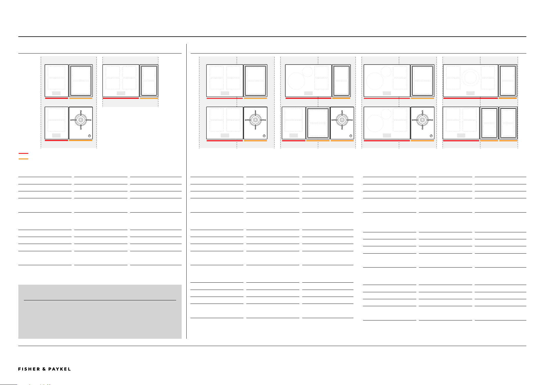
© FISHER & PAYKEL LIMITED 2025 PAGE 3390003312C PLANNING GUIDE MoDULAR CooKToPS VERSIoN C - MAY 2025
The models shown in this Planning Guide may not be available in all markets and are subject to change at any time. Product specifications may vary from those shown. This Planning Guide should not be used as installation guidance for any product. Further information is required to safely and correctly install the
products featured here. Specific installation guidance will be available with the product on delivery and on our website fisherpaykel.com
TYPICAL CONFIGURATIONS WITH OVERHEAD VENTILATION
1 TWO IN A ROW - 15 + 15
Dimensions W x D x H
in
mm
Combined Module Size 30 3/8 x 20 7/8 x 2 5/16
772 x 530 x 58
Proud cutout 28 15/16 x 19 31/32
734 x 507
Flush cutout 28 15/16 x 20 1/16
734 x 509
Flush recess 30 9/16 x 21 1/32 x 1/4
776 x 534 x 6.5
2 TWO IN A ROW - 24 + 12
Dimensions W x D x H
in
mm
Combined Module Size 35 1/2 x 20 7/8 x 3 1/2
902 x 530 x 89
Proud cutout 33 15/16 x 19 31/32
862 x 507
Flush cutout 33 15/16 x 20 1/16
862 x 509
Flush recess 35 11/16 x 21 1/32 x 1/4
906 x 534 x 6.5
*Glass overhang at sides adjusted to fit 35 7/16" (900mm) cabinet constructed from 3/4"
(19mm) panels. 34 1/8" (864mm) width cutout recommended if cabinetry construction
allows.
3 TWO IN A ROW - 24 + 15
Dimensions W x D x H
in
mm
Combined Module Size
38 7/8 x 20 7/8 x 3 1/2
987 x 530 x 89
Proud cutout
37 3/8 x 19 31/32
949 x 507
Flush cutout
37 3/8 x 20 1/16
949 x 509
Flush recess
39 1/32 x 21 1/32 x 1/4
991 x 534 x 6.5
4 TWO IN A ROW - 30 + 12
Dimensions W x D x H
in
mm
Combined Module Size
41 13/16 x 20 7/8 x 3 1/2
1062 x 530 x 89
Proud cutout
40 5/16 x 19 31/32
1024 x 507
Flush cutout
40 5/16 x 20 1/16
1024 x 509
Flush recess
42 x 21 1/32 x 1/4
1066 x 534 x 6.5
5 THREE IN A ROW - 15 + 15 + 15 *
Dimensions W x D x H
in
mm
Combined Module Size
45 5/8 x 20 7/8 x 3 1/2
1159 x 530 x 89
Proud cutout
44 1/8 x 19 31/32
1121 x 507
Flush cutout
44 1/8 x 20 1/16
1121 x 509
Flush recess
45 13/16 x 21 1/32 x 1/4
1163 x 534 x 6.5
* Primary and auxiliary cooktops must be adjacent due to communication cable. Gas must
be positioned on outside.
1 TWO IN A ROW - 30 + 15
Dimensions W x D x H
in
mm
Combined Module Size
45 3/16 x 20 7/8 x 3 1/2
1147 x 530 x 89
Proud cutout
43 11/16 x 19 31/32
1109 x 507
Flush cutout
43 11/16 x 20 1/16
1109 x 509
Flush recess
45 5/16 x 21 1/32 x 1/4
1151 x 534 x 6.5
6 TWO IN A ROW - 36 + 12
Dimensions W x D x H
in
mm
Combined Module Size
47 5/16 x 20 7/8 x 3 1/2
1202 x 530 x 58
Proud cutout
45 7/8 x 19 31/32
1164 x 507
Flush cutout
45 7/8 x 20 1/16
1164 x 509
Flush recess
47 1/2 x 21 1/32 x 1/4
1206 x 534 x 6.5
7 THREE IN A ROW - 24 + 12 + 12
Dimensions W x D x H
in
mm
Combined Module Size
47 7/16 x 20 7/8 x 3 1/2
1204 x 530 x 58
Proud cutout
45 15/16 x 19 31/32
1166 x 507
Flush cutout
45 15/16 x 20 1/16
1166 x 509
Flush recess
47 9/16 x 21 1/32 x 1/4
1208 x 534 x 6.5
MID < 36"
WIDE < 48"
IMPORTANT NOTE
Other configurations are possible.
Cutout widths may not be possible in certain countertop materials.
Please refer to countertop suppliers recommendations for material
parameters and fabrication recommendations.
PRIMARY COOKTOP
AUXILIARY OR GAS ON GLASS COOKTOP
36"
1
2
15" 15"
24" 12"
24" 24"
3
4
6
24" 15"
30" 12"
30" 15"
24" 24"
7
8
24" 12" 12"
36" 12"
PLANNING CONSIDERATIONS | MODULAR COOKTOPS
1
15" 15"
6
30" 15"
24" 24"
3
36"
24" 24"
24" 15"
5
15" 15" 15"
<< CONTENTS
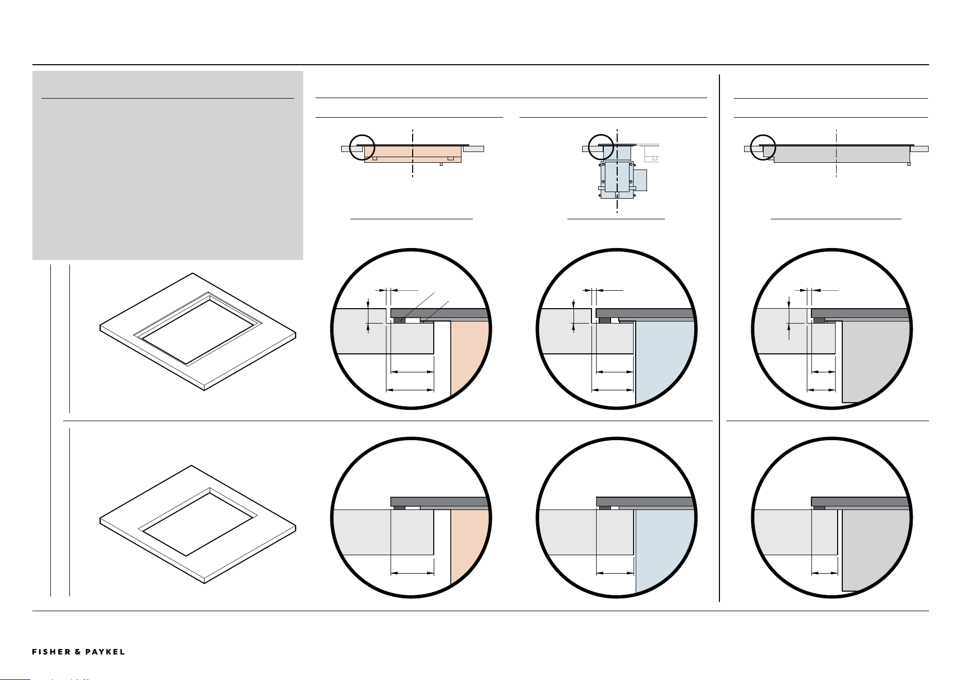
© FISHER & PAYKEL LIMITED 2025 PAGE 3490003312C PLANNING GUIDE MoDULAR CooKToPS VERSIoN C - MAY 2025
The models shown in this Planning Guide may not be available in all markets and are subject to change at any time. Product specifications may vary from those shown. This Planning Guide should not be used as installation guidance for any product. Further information is required to safely and correctly install the
products featured here. Specific installation guidance will be available with the product on delivery and on our website fisherpaykel.com
5/8"
(16mm)
COUNTERTOP INSTALLATION DETAILS
7/16"
(11.5mm)
FRoNT VIEW PRoFILE VIEW FRoNT VIEW
SIDE OVERHANGS
COOKTOP MODULES DOWNDRAFT MODULE
FRONT + REAR OVERHANG
ALL MODULES
COUNTERTOP DETAIL
PROUD FLUSH
COUNTERTOP INSTALLATION
A flush or proud finish between the top surface of the modules
and countertop is achievable.
Some overhang details are common left to right or front to back,
however there are small dimensional changes between proud and
flush, cooking modules and ventilation module.
Care needs to be taken during planning and fabrication to ensure
successful installation of modules.
Shimming may be required during flush installation.
13/32"
(10.5mm)
1/2"
(12.5mm)
5/32"
(2mm)
1/4"
(6.5mm)
3/4"
(19mm)
1/4"
(6.5mm)
23/32"
(18mm)
5/8"
(16mm)
5/32"
(2mm)
1/4"
(6.5mm)
3/4"
(19mm)
27/32"
(21mm)
5/32"
(2mm)
FOAM TAPE
SHIM
PLANNING CONSIDERATIONS | MODULAR COOKTOPS
<< CONTENTS
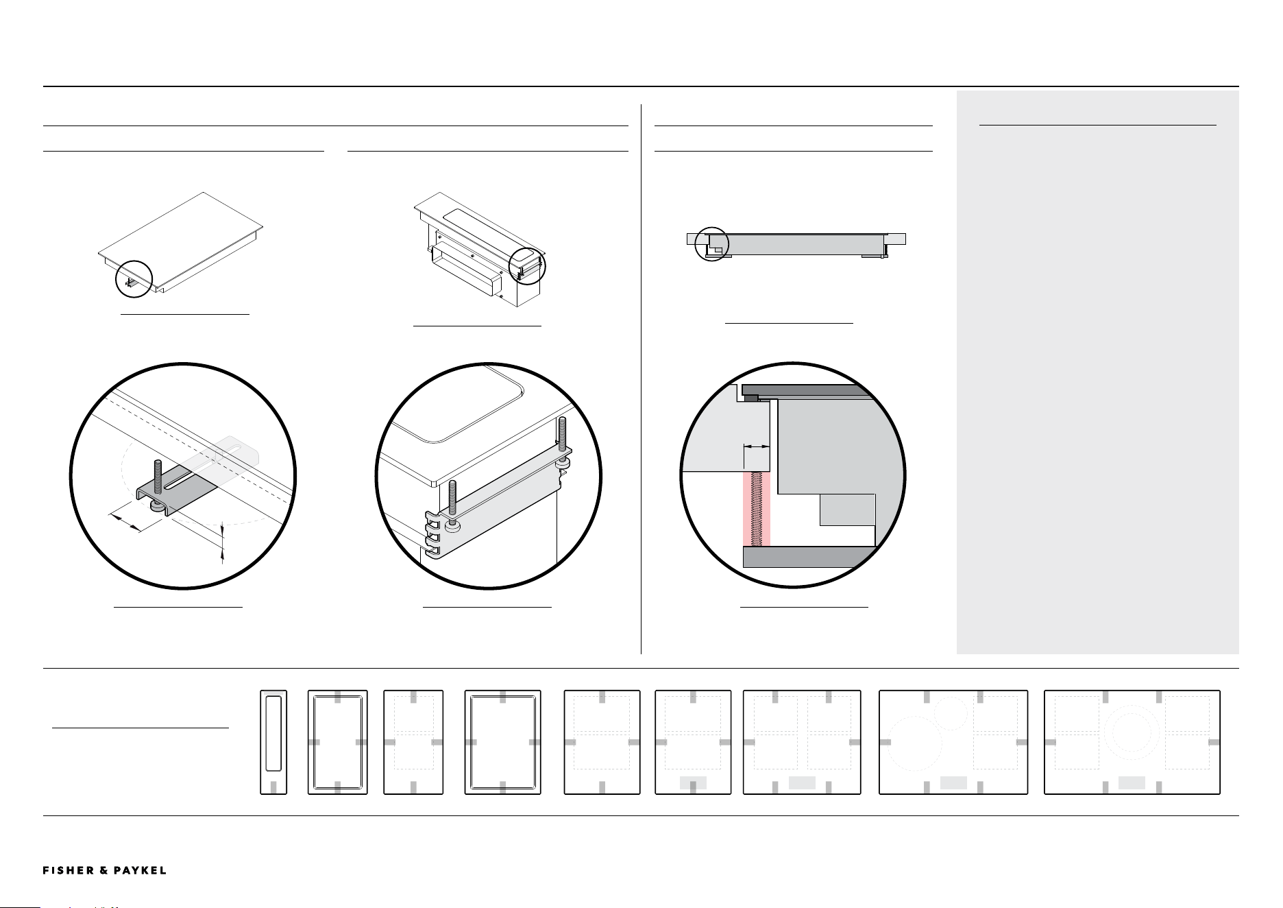
© FISHER & PAYKEL LIMITED 2025 PAGE 3590003312C PLANNING GUIDE MoDULAR CooKToPS VERSIoN C - MAY 2025
The models shown in this Planning Guide may not be available in all markets and are subject to change at any time. Product specifications may vary from those shown. This Planning Guide should not be used as installation guidance for any product. Further information is required to safely and correctly install the
products featured here. Specific installation guidance will be available with the product on delivery and on our website fisherpaykel.com
CLAMPS
Clamps are supplied with modules to secure
their position to benchtop. There are two
types, common and rear downdraft.
It is recommended to have 7/16" (10mm)
clearance from edge of cutout for clamp
engagement.
Clamps are attached to chassis at fixed
hole locations. A minimum of 2 clamps are
required per module, it is recommended they
are positioned on opposite sides of each
module eg. left and right or front and rear.
For more details please refer to Install Guide.
CLAMP FIXING LOCATIONS
PLAN VIEW
Minimum of 2 clamps per module.
DETAIL A
Can be rotated and moved
horizontally
ISo FRoNT VIEW
ISo REAR VIEW
SIDE VIEW
CLEARANCE REQUIREMENTS
ALL MODULES
BRACKET TYPES
COMMON BRACKET REAR DOWNDRAFT BRACKET
Applies to all bracket locations, excluding rear downdraft
7/16"
(10mm)
1 1/16"
(25mm)
7/16"
(10mm)
15" 24"12" 30" 36"15" 15"12"
DETAIL B
Bracket can be repositioned
vertically
A
B
C
DETAIL C
Minimum clearance common
to all brackets left/right and
front/rear
CLAMPING LOCATIONSPLANNING CONSIDERATIONS | MODULAR COOKTOPS
<< CONTENTS

© FISHER & PAYKEL LIMITED 2025 PAGE 3690003312C PLANNING GUIDE MoDULAR CooKToPS VERSIoN C - MAY 2025
The models shown in this Planning Guide may not be available in all markets and are subject to change at any time. Product specifications may vary from those shown. This Planning Guide should not be used as installation guidance for any product. Further information is required to safely and correctly install the
products featured here. Specific installation guidance will be available with the product on delivery and on our website fisherpaykel.com
COOKTOP VENTILATION REQUIREMENTS
VENTILATION REQUIREMENTS
Air intake at rear, outlet at front
CLEARANCE REQUIREMENTS
Induction and Tepanyaki
modules require clearance
below chassis to ensure air flow.
A
FRONT REAR
SERVICE CHANNEL INTAKE
Service channel at back of
cabinetry, where fresh air is
drawn up from kick cavity.
If cavity is tightly sealed,
ventilation holes in kick panel
are required.
ADJACENT CABINET INTAKE
2x Ø2" (Ø50mm) holes are
required in each side wall
through to adjacent cabinets.
Total of 4x holes required.
b
c
SIDE VIEW
1
1
FRoNT VIEW
DATUM: WIDTH OF
CHASSIS
RAIL
Single cutout in rail, full width of
chassis, 3/16" (4mm) high.
Example of alternate cutout
where equivalent ventilation
area is achieved.
EXAMPLE VENTILATION CUTOUTS
VENTILATION OUTLET
Hot air from Induction and Tepanyaki modules must be able to exit at front of
cabinets, the most direct route is recommended.
The detail below shows one solution where cutouts have been made in the
support rail at front of cabinet, other routes are possible but must meet
dimensional guidelines in table.
50mm
BENCHTOP
RAIL
FRONT PANEL
AIR VENT
D
DETAIL 1
SIDE VIEW
PLANNING CONSIDERATIONS | MODULAR COOKTOPS
VENTILATION OVERVIEW
The Induction and Tepanyaki modules require ventilation to allow cooling of
the electronic components within the chassis. Cooling fans are located on the
base of the product drawing cool air into the rear of the product while hot air
exits from vents at the front.
Provisions are required in cabinetry to allow fresh air to enter and hot air to
exit to ensure product ventilation and optimum product performance.
When multiple products are installed their individual ventilation requirements
must also be combined.
Gas on Glass modules do not require ventilation.
CLEARANCE REQUIREMENTS in mm
A Clearance below chassis from top of cook surface
Induction 12", 15" 2 7/ 8 72
Induction 24", 30", 36" 3 5/8 91
Teppanyaki 12", 15" 3 7/16 86
Gas on Glass 15" 3 76
VENTILATION REQUIREMENTS * in mm in
2
cm
2
INTAKE at rear
B via service channel, min depth 13/16 20 - -
C through adjacent cabinets, per side wall** 2x Ø2" 2x Ø50 6.2 40
OUTLET at front*
D 3/16" (4mm) gap along width of chassis
12" 10 1/16 x 3/16 255 x 4 1.6 10
15" 13 3/8 x 3/16 340 x 4 2.2 14
24" 21 7/8 x 3/16 555 x 4 3.4 22
30" 29 15/16 x 3/16 715 x 4 4.7 30
36" 33 11/16 x 3/16 855 x 4 5.3 34
* Not required for Gas on Glass modules
** Vents with equivalent-sized area possible. Must be positioned in front of product.
<< CONTENTS
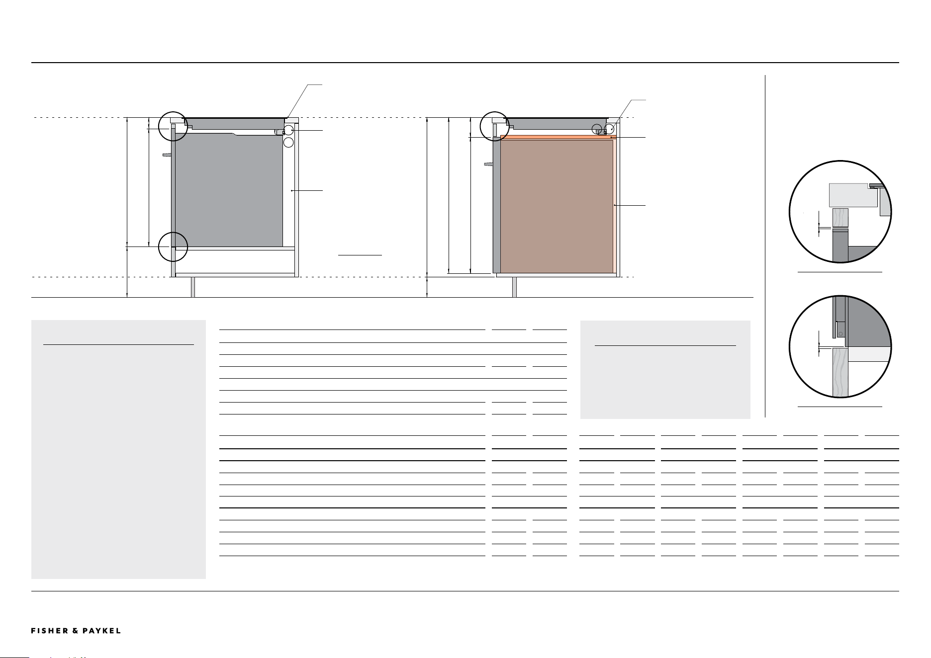
© FISHER & PAYKEL LIMITED 2025 PAGE 3790003312C PLANNING GUIDE MoDULAR CooKToPS VERSIoN C - MAY 2025
The models shown in this Planning Guide may not be available in all markets and are subject to change at any time. Product specifications may vary from those shown. This Planning Guide should not be used as installation guidance for any product. Further information is required to safely and correctly install the
products featured here. Specific installation guidance will be available with the product on delivery and on our website fisherpaykel.com
COOKTOP INSTALLATION WITH BUILT IN OVENS
FLUSH INSTALLATION
Heights based on glass finished flush with countertop.
For proud installation glass finishes 1/4" (6mm) higher
than countertop.
PLANNING CONSIDERATIONS | MODULAR COOKTOPS
CABINETRY DIMENSION OVERVIEW in mm in mm in mm in mm in mm
24" OVEN OB24 Induction 24" 30" 36" Induction 12", 15" Teppanyaki 12", 15" Gas on Glass 15" Modular Ventilation
C Minimum height from top of cooksurface to top of oven
2 7/16
61
1 15/16
49
2 1/2
63
2 1/8
53
6 7/16
164
D Minimum height from top of cooksurface to bottom of oven
25 15/16
659
25 1/2
647
26
661
25 5/8
651
30
762
E Resulting height from bottom of oven to floor *
10 1/16
255
10 1/2
267
10
253
10 3/8
263
6
152
30" OVEN OB30 Induction 24" 30" 36" Induction 12", 15" Teppanyaki 12", 15" Gas on Glass 15" Modular Ventilation
F Minimum height from top of cooksurface to top of oven
4
102
3 1/4
83
3 13/16
97
3 7/16
87
7 13/16
198
G Minimum height from top of cooksurface to bottom of oven
31 1/8
791
30 7/8
772
30 15/16
786
30 9/16
776
34 15/16
887
H Minimum height from top of cooksurface to bottom of cabinet **
31 7/8
810
31 1/8
791
31 11/16
805
31 5/16
795
35 11/16
906
I Resulting kick height from bottom of cabinet * **
4
104
4 13/16
123
4 5/16
109
4 11/16
119
5/16
8
* Based on countertop height of 36" (914mm) with cooktops installed flush with countertop, with cooktops and ovens installed to mimimum clearance specifications.
** Nominal panel thickness of 3/4" (19mm) used for cabinetry carcass and dividing panel. Thickness of panels can be reduced if airtightness and sucient strength to support oven can be maintained.
DETAIL A - ToP oF oVEN
1/16"
(2mm)
DETAIL B - BASE oF oVEN
1/16"
(2mm)
OVEN CLEARANCE TO PANELS
A minimum vertical clearance of
1/16" (2mm) is required between
ovens and cabinetry front panels.
The clearance above an oven
can contribute to ventilation
requirements of cooktops (refer
previous page).
914
104
AD
VENTILATION HOLES
Ventilation for cooktops must
not penetrate oven cavity.
c
bg
F
h
SEALED CAVITY
30" Ovens must be installed
in a separate cavity to the
cooktops. Ensure the cavity
is completely sealed with no
gaps. This is to ensure the
oven cooling system functions
correctly.
e
i
DIVIDING PANEL
Creates sealed cavity for 30"
Oven. Must be removeable to
allow for clamping of cooktops
during installation.
A
B
A
VENTILATION HOLES
Ventilation for cooktops
does not impact
performance of 24"
ovens.
PRODUCT CAVITY
24" Ovens can be
installed in the same
cavity as cooktops.
36" (914mm)
4" (102mm)
FISHER & PAYKEL 30" OVEN
FISHER & PAYKEL 24" OVEN
DATUM: TOP OF COOKSURFACE,
COUNTER TOP (FLUSH INSTALL)
INSTALLATION WITH OVENS
Fisher & Paykel 24" and 30" Built in
Ovens can be installed under modular
cooktops.
This overview is based on minimum
vertical clearance requirements
between cooktop, oven and cabinetry
(where required). A benchtop height
of 36" (914mm) has been used for
calculations.
When installing mulitple cooktops
the product with the greatest height
to oven should be used to determine
cabinetry requirements.
BUILT IN OVEN DIMENSIONS in mm
24" OVEN - OB24SDPTDX2, OB24SMPTDB1, OB24SMPTNB1, OB24SD16PLX1, OB24SD11PLX1, OB24SCD9PB1
A Height of oven
23 9/16
598
Width of oven
23 7/16
596
30" OVEN - OB30SPPTX1, OB30SDPTDB1, OB30SDPTDX2, OB30SD17PLX1, OB30SD14PLX1
B Height of oven
27 3/16
690
Width of oven
29 15/16
760
INSTALLATION WITH OVENS
For complete oven specifications
please refer to specific Planning
Guide, Installation Guide and CAD.
SIDE VIEW
<< CONTENTS
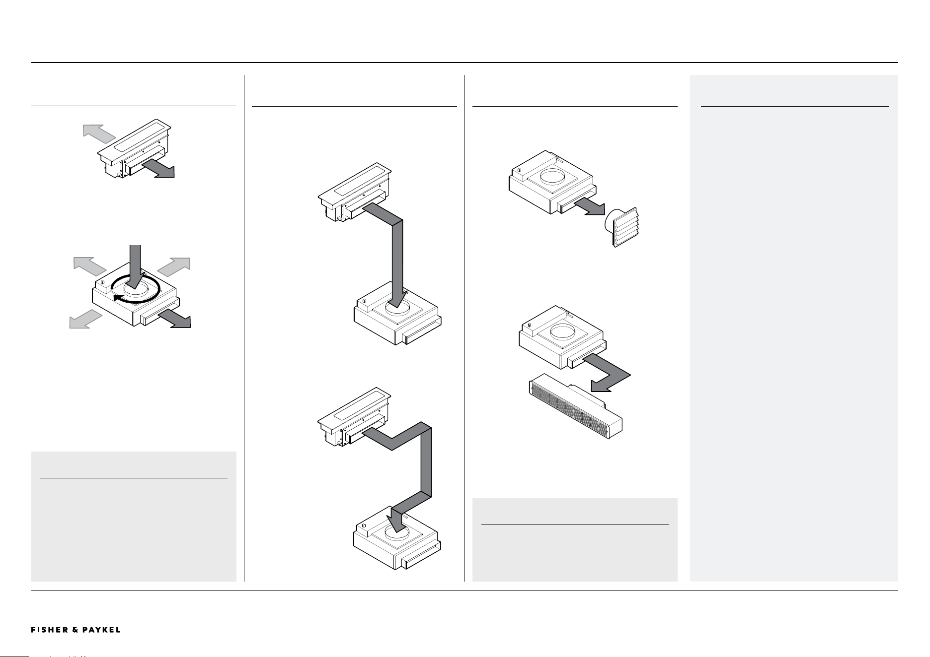
© FISHER & PAYKEL LIMITED 2025 PAGE 3890003312C PLANNING GUIDE MoDULAR CooKToPS VERSIoN C - MAY 2025
The models shown in this Planning Guide may not be available in all markets and are subject to change at any time. Product specifications may vary from those shown. This Planning Guide should not be used as installation guidance for any product. Further information is required to safely and correctly install the
products featured here. Specific installation guidance will be available with the product on delivery and on our website fisherpaykel.com
MODULAR VENTILATION COMPONENTS
MAINBOX
Outlet can be positioned to the left or right.
BLOWERBOX
Can be rotated 360° to allow a variety of outlet directions.
OUTLET
MODULAR VENTILATION COMPONENTS
INTAKE
IMPORTANT
Blowerbox inlet and outlet are offset, component
is not symmetrical.
CARE TO BE TAKEN WHEN PLANNING.
It is essential to work with CAD downloads of
modular ventilation components to design a
ducting layout best suited to specific cabinetry
requirements.
MODULAR VENTILATION
The Auxiliary Modular Ventilation system is
comprised of two key components, the mainbox
and blowerbox. The mainbox is positioned
alongside modular cooktops in the countertop,
while the blowerbox can be positioned on the
floor within cabinetry or below the floor eg.
basement.
The units are supplied with 3.25" x 12" outlets
which will accommodate metal ducting of
equivalent size. Alternate outlet adapters are
available to suit 2.25" x 12" duct systems.
IMPORTANT:
Model not supplied with ducting.
Use only metal ductwork to reduce the risk of
fire. Do not use flexible ducting.
Venting directly into the cabinet with no vent
is not permitted. Do not vent exhaust air into
spaces within the walls or ceilings or into attics,
crawl spaces, or garages.
WARNING:
The Modular Ventilation unit cannot be used
alongside a gas cooktop.
PLANNING CONSIDERATIONS | MODULAR COOKTOPS
SERVICE CHANNEL
Ducting routed through service
channel at rear of cabinet or behind
cabinet.
DIRECT
Minimal bends. Ducting routed
within cabinet.
Indicative of routing for AHAM
test.
DUCT ROUTING
Representational airflow showing indicative routing
for ducting.
VENTING
Ventilation can be externally vented or recirculated
internally.
EXTERNAL VENTILATION
Blowerbox is connected to grille
which vents air outside of building.
INTERNAL RECIRCULATION
Blower box is connect to Recirculation Kit
(accessory KRECIRCDDFT).
Air is filtered before being vented internally into buiding.
IMPORTANT
Air vented from multiple blower boxes must be
not be connected to a common external vent or
recirculation kit.
<< CONTENTS
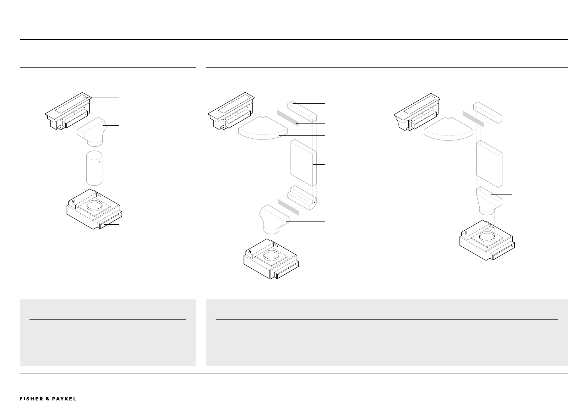
© FISHER & PAYKEL LIMITED 2025 PAGE 3990003312C PLANNING GUIDE MoDULAR CooKToPS VERSIoN C - MAY 2025
The models shown in this Planning Guide may not be available in all markets and are subject to change at any time. Product specifications may vary from those shown. This Planning Guide should not be used as installation guidance for any product. Further information is required to safely and correctly install the
products featured here. Specific installation guidance will be available with the product on delivery and on our website fisherpaykel.com
ROUTING THROUGH SERVICE CHANNEL
ELBOW, 90°
not supplied.
RECTANGULAR DUCT
Cut to length,
not supplied.
Additional straight ducting
FLAT ELBOW, 90°
not supplied.
ADAPTER, 90°
Rectangular to 6" diameter.
not supplied.
ELBOW, 90°
not supplied.
MAINBOX
Supplied with 3.25" x 12" outlet,
alternate 2.25" x 12" outlet available.
PLANNING CONSIDERATIONS | MODULAR COOKTOPS COMMON DUCTING SCENARIOS
ROUND DUCT, 6" DIAMETER
Cut to length, not supplied.
ADAPTER, 90°
not supplied
DIRECT ROUTING
IMPORTANT
AHAM test performed with direct routing.
BLOWERBOX
6" diameter inlet.
Supplied with 3.25" x 12" outlet,
alternate 2.25" x 12" outlet adapter
available.
DUCTING SCENARIO EXAMPLES
Diagrams are to provide examples of possible ducting layouts.
Ducting components and layout are indicative only and should be adapted to suit specific cabinetry requirements.
Ducting is shown for reference only. Fisher & Paykel does not supply ducting parts. These can be purchased from most hardware stores.
ADAPTER, STRAIGHT
Rectangular to 6" diameter,
not supplied.
<< CONTENTS
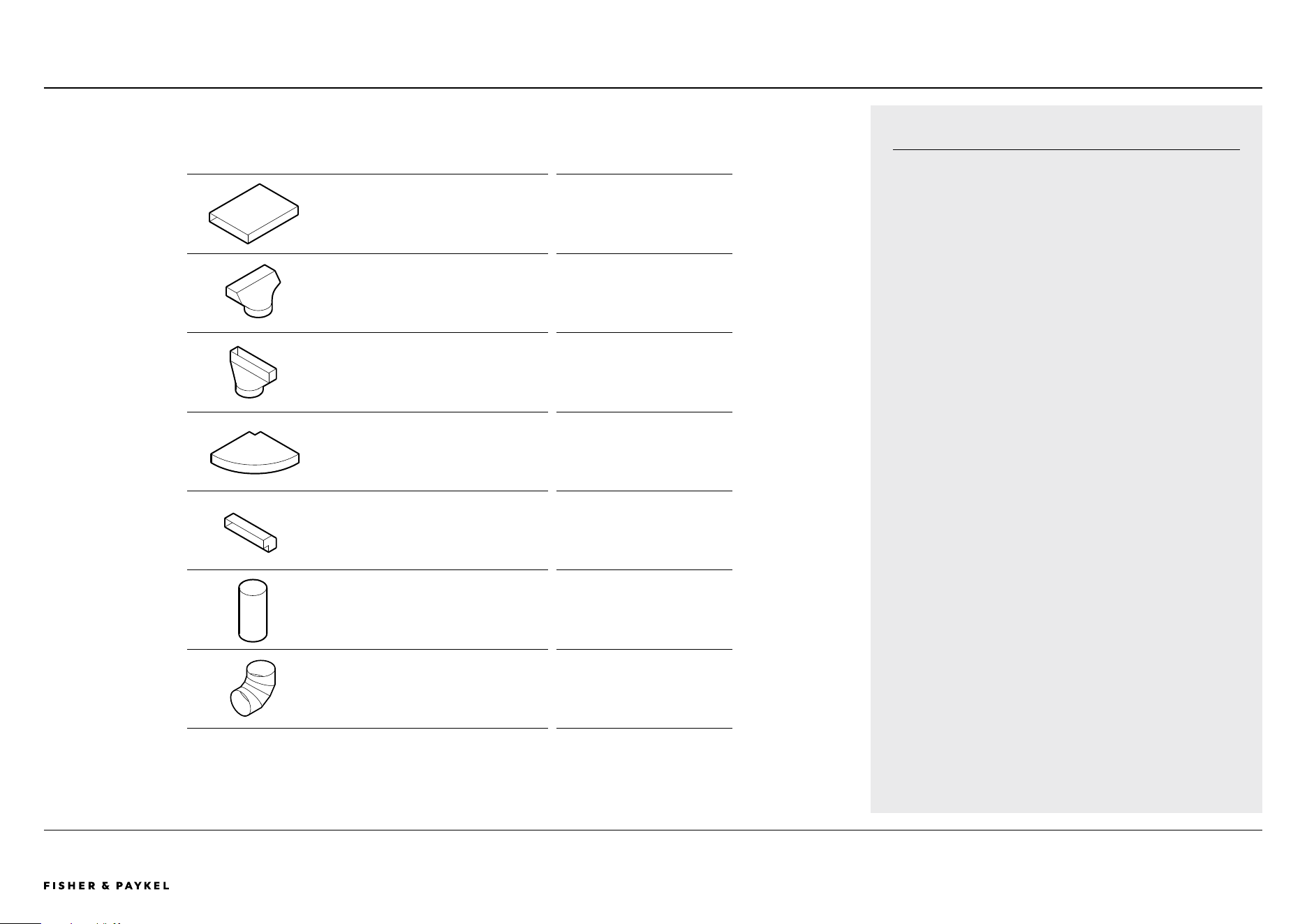
© FISHER & PAYKEL LIMITED 2025 PAGE 4090003312C PLANNING GUIDE MoDULAR CooKToPS VERSIoN C - MAY 2025
The models shown in this Planning Guide may not be available in all markets and are subject to change at any time. Product specifications may vary from those shown. This Planning Guide should not be used as installation guidance for any product. Further information is required to safely and correctly install the
products featured here. Specific installation guidance will be available with the product on delivery and on our website fisherpaykel.com
PLANNING CONSIDERATIONS | MODULAR COOKTOPS DUCT LENGTH RECOMMENDATIONS
COMPONENT EQUIVALENT LENGTH OF 3.25X12”
Metal straight ducting – 1ft length
(3.25x12”)
1 ft
Metal rectangular to round bend - 90°
(3.25x12” to 6”)
5 ft
Metal rectangular to round transition – straight
(3.25x12” to 6”)
4ft
Metal horizontal bend - 90°
(3.25x12”)
17 ft
Metal vertical bend - 90°
(3.25x12”)
25 ft
Metal straight ducting – 1ft length
(6” round)
1.7 ft
Round Metal bend - 90°
(6” round)
17 ft
RECOMMENDED DUCT LENGTH
3.25 x 12" ducting components are recommended for optimum
extraction performance.
Total equivalent length of ducting after the blower box is
recommended to be less than 100ft.
Refer to table for estimated equivalent lengths for various duct
components. Wall outlet cap has been taken into consideration.
Do not include in equivalent feet calculations.
Fisher & Paykel does not supply ducting components.
<< CONTENTS
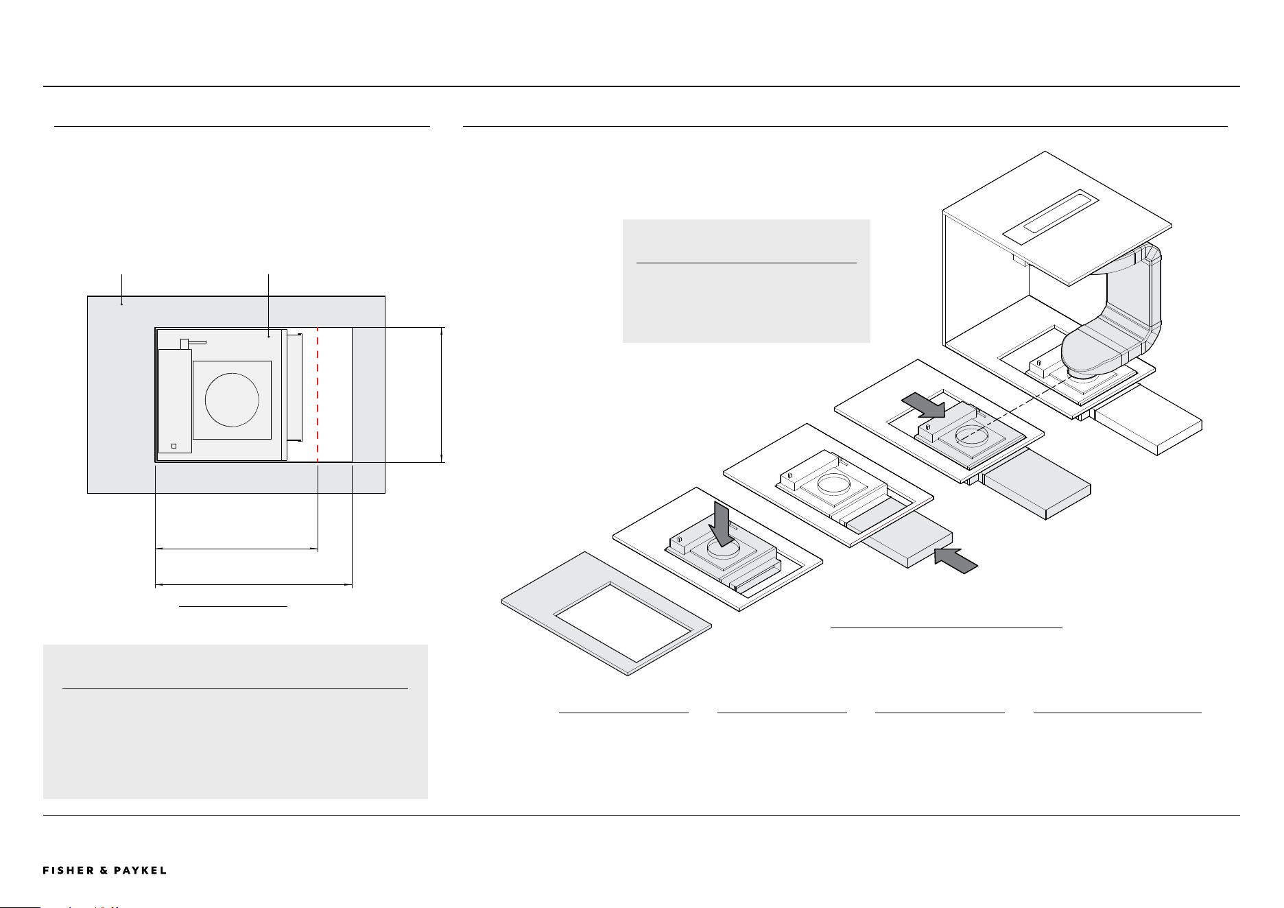
© FISHER & PAYKEL LIMITED 2025 PAGE 4190003312C PLANNING GUIDE MoDULAR CooKToPS VERSIoN C - MAY 2025
The models shown in this Planning Guide may not be available in all markets and are subject to change at any time. Product specifications may vary from those shown. This Planning Guide should not be used as installation guidance for any product. Further information is required to safely and correctly install the
products featured here. Specific installation guidance will be available with the product on delivery and on our website fisherpaykel.com
BLOWERBOX CABINETRY
18 1/2" (470MM) MINIMUM
22 7/16" (570MM) RECOMMENDED
15 3/8" (390MM)
MINIMUM
ISoMETRIC VIEW
PLAN VIEW
CABINETRY FLOOR PANEL BLOWERBOX
BLOWERBOX CUTOUT
The Blowerbox requires a minimum cutout of 15 3/8" x 18 1/2" (390mm x
470mm) in base of cabinetry so it can be positioned on the floor.
For ease of installation and connection to outlet ducting it is
recommended that the cutout is increased to 15 3/8" x 22 7/16" (390mm
x 570mm).
IMPORTANT
The position of the cutout may not be central to floor panel.
Pre-planning is required. It is essential to work with CAD
downloads of modular ventilation components to design a layout
suited to specific cabinetry requirements.
BLOWERBOX INSTALLATION OVERVIEW
1
Cut hole in bottom of
cabinetry panel
2
Lower blowerbox onto
floor.
3
Oversized hole allows
access to connect
ducting
4
Blowerbox repositioned to
achieve alignment with ducting.
PLEASE NOTE
Ducting is not included.
Illustration is representational only.
PLANNING CONSIDERATIONS | MODULAR COOKTOPS
<< CONTENTS
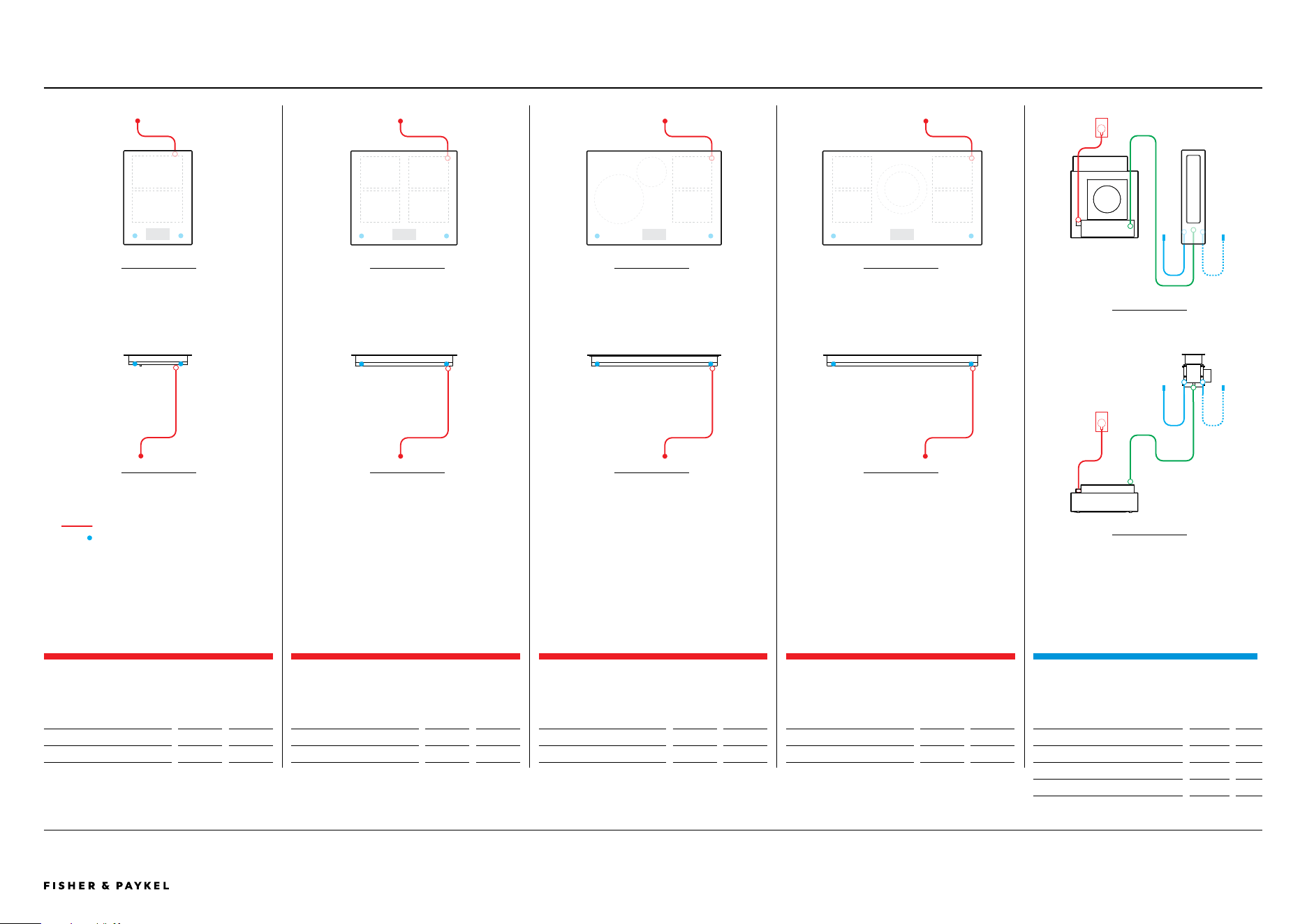
© FISHER & PAYKEL LIMITED 2025 PAGE 4290003312C PLANNING GUIDE MoDULAR CooKToPS VERSIoN C - MAY 2025
The models shown in this Planning Guide may not be available in all markets and are subject to change at any time. Product specifications may vary from those shown. This Planning Guide should not be used as installation guidance for any product. Further information is required to safely and correctly install the
products featured here. Specific installation guidance will be available with the product on delivery and on our website fisherpaykel.com
SERVICES
PRIMARY MODULAR INDUCTION COOKTOP, 15"
2 ZONES WITH SMARTZONE
Model no:
CI152DTTB1
Dimensions
in
mm
Power Cable
74 13/16
1900
PRIMARY MODULAR INDUCTION COOKTOP, 24"
4 ZONES WITH SMARTZONE
Model no:
CI244DTTB1
Dimensions
in
mm
Power Cable
54 5/16
1380
PRIMARY MODULAR INDUCTION COOKTOP, 30"
4 ZONES WITH SMARTZONE
Model no:
CI304DTTB1
Dimensions in
mm
Power Cable 54 5/16
1380
PRIMARY MODULAR INDUCTION COOKTOP, 36"
5 ZONES WITH SMARTZONE
Model no:
CI365DTTB1
Dimensions
in
mm
Power Cable
54 5/16
1380
FRoNT VIEW
ToP VIEW
FRoNT VIEW
ToP VIEW
FRoNT VIEW
ToP VIEW
FRoNT VIEW
ToP VIEW
POWER CABLE
COMMUNICATION PORT
PLANNING CONSIDERATIONS | MODULAR COOKTOPS
AUXILIARY MODULAR VENTILATION, 5"
Model no:
CD5DB1
Dimensions
in
mm
External Communication Harness*
19 11/16
500
Central Communication Harness*
66 15/16
1700
Power Cable
28
720
* x1 supplied with each auxiliary unit
FRoNT VIEW
ToP VIEW
<< CONTENTS
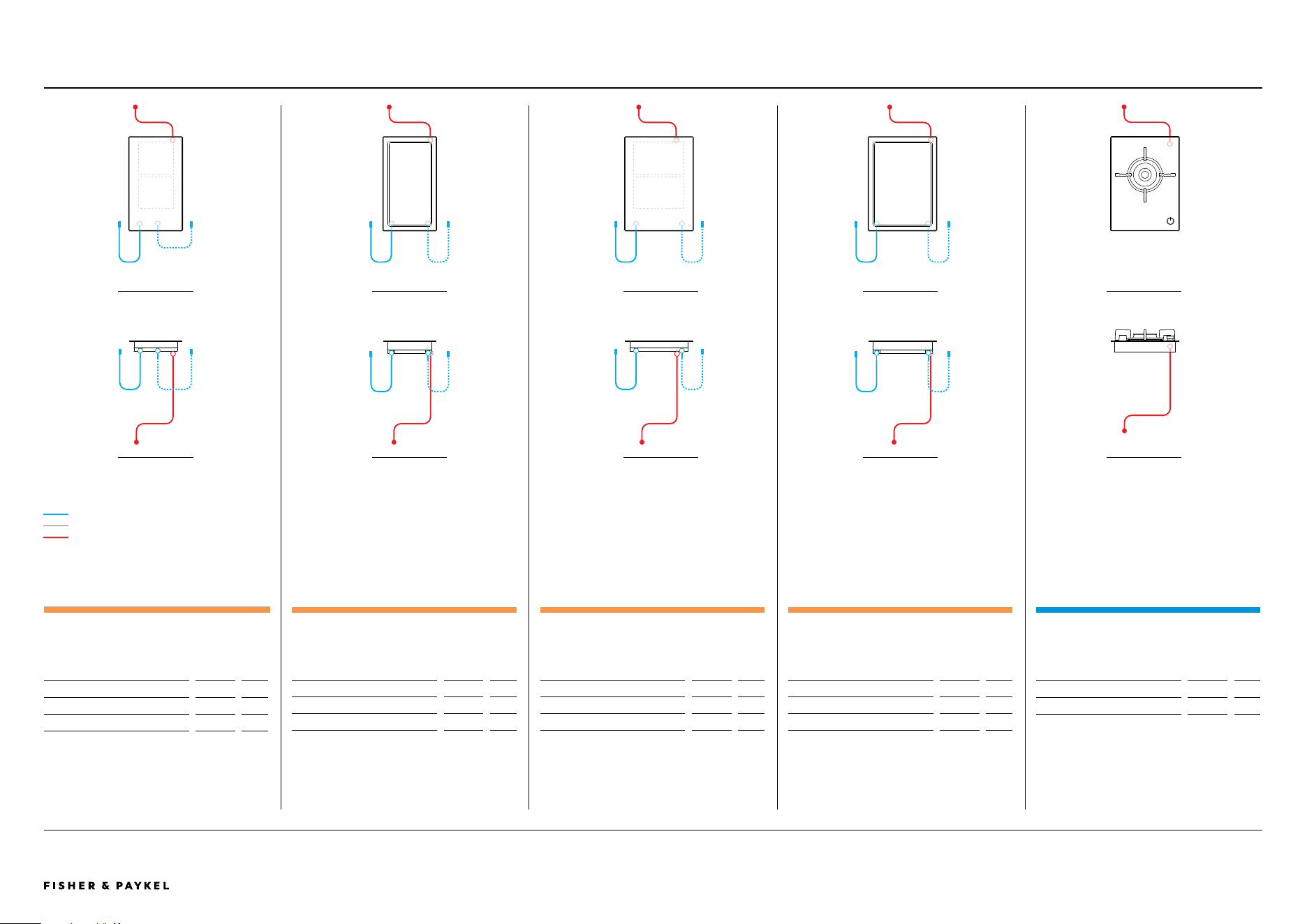
© FISHER & PAYKEL LIMITED 2025 PAGE 4390003312C PLANNING GUIDE MoDULAR CooKToPS VERSIoN C - MAY 2025
The models shown in this Planning Guide may not be available in all markets and are subject to change at any time. Product specifications may vary from those shown. This Planning Guide should not be used as installation guidance for any product. Further information is required to safely and correctly install the
products featured here. Specific installation guidance will be available with the product on delivery and on our website fisherpaykel.com
SERVICES
AUXILIARY MODULAR TEPPANYAKI COOKTOP, 12",
2 ZONES
Model no:
CIT122DX1
Dimensions
in
mm
External Communication Harness*
19 11/16
500
Power Cable*
74 13/16
1900
* x1 supplied with each auxiliary unit
AUXILIARY MODULAR INDUCTION COOKTOP, 12",
2 ZONES WITH SMARTZONE
Model no:
CI122DB1
Dimensions
in
mm
External Communication Harness*
19 11/16
500
Power Cable*
74 13/16
1900
* x1 supplied with each auxiliary unit
AUXILIARY MODULAR INDUCTION COOKTOP, 15",
2 ZONES WITH SMARTZONE
Model no:
CI152DB1
Dimensions
in
mm
External Communication Harness*
19 11/16
500
Power Cable*
74 13/16
1900
* x1 supplied with each auxiliary unit
AUXILIARY MODULAR TEPPANYAKI COOKTOP, 15",
2 ZONES
Model no:
CIT152DX1
Dimensions
in
mm
External Communication Harness*
19 11/16
500
Power Cable*
74 13/16
1900
* x1 supplied with each auxiliary unit
GAS ON GLASS MODULAR COOKTOP, 15"
Model no:
CG151DLPGB5 LPG
CG151DNGGB5 Natural Gas
Dimensions
in
mm
Power Cable
45 11/16
1160
FRoNT VIEW
ToP VIEW
FRoNT VIEW
ToP VIEW
FRoNT VIEW
ToP VIEW
FRoNT VIEW
ToP VIEW
FRoNT VIEW
ToP VIEW
EXTERNAL COMMUNICATION HARNESS
CENTRAL COMMUNICATION HARNESS
POWER CABLE
PLANNING CONSIDERATIONS | MODULAR COOKTOPS
<< CONTENTS
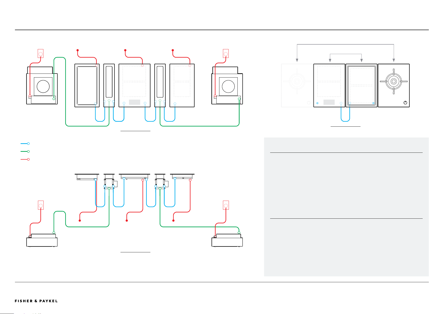
© FISHER & PAYKEL LIMITED 2025 PAGE 4490003312C PLANNING GUIDE MoDULAR CooKToPS VERSIoN C - MAY 2025
The models shown in this Planning Guide may not be available in all markets and are subject to change at any time. Product specifications may vary from those shown. This Planning Guide should not be used as installation guidance for any product. Further information is required to safely and correctly install the
products featured here. Specific installation guidance will be available with the product on delivery and on our website fisherpaykel.com
MODULAR CONNECTIONS
FRoNT VIEW
ToP VIEW
EXTERNAL COMMUNICATION HARNESS
CENTRAL COMMUNICATION HARNESS
POWER CABLE
SUPPLIED HARNESS
External communication harnesses connect auxiliary modules to the primary module.
These connections must be to the product directly adjacent in a 'daisy chain'
configuration (refer diagram). Gas on glass modules do not require a communication
harness and must not be placed between primary and auxiliary modules.
1x External communication harness is supplied with each auxiliary module (induction,
teppanyaki and downdraft ventilation).
1x Central communication harness is supplied with auxiliary modular ventilation to
connect downdraft mainbox with blowerbox.
ELECTRICAL SERVICE FOR MULTIPLE PRODUCT INSTALLS
Where multiple products are being installed together, it is possible to use a smaller
local distribution board, rather than running multiple separate lines. For example, 2 x
15 A modules can be connected via a single 30 A breaker.
This cooktop must be connected to the mains power supply only by a suitably
qualified person.
PLANNING CONSIDERATIONS | MODULAR COOKTOPS
ToP VIEW
Gas on Glass module(s) must be postioned on outside
Position of primary and auxiliary modules can be interchanged
<< CONTENTS