Operator’s Manual
www.mechmaxx.com
WARRANTY


1
www.mechmaxx.com
TRADEMARKS AND COPYRIGHTS
Compressor User's Manual 2024. No part of this manual
may be reproduced, adapted, or disseminated without
permission.
The trademarks on the products belong to their regis-
trants.
PRODUCT DESCRIPTION
The manufacturer has the right to design changes of
products and is not responsible for obligation to modify
and improve the products that have been shippied. We
may make modifications to the specifications or compo-
nents of certain products in the future without prior
notice.
MATTERS NEEDING ATTENTION
Before using the equipment, be sure to read this manual
and understand various contents, so as to correctly
install, debug, operate, and maintain the equipment. This
manual should be kept in the hands of the actual end user.
Be sure to keep this manual and the supporting docu-
ments with the air compressor together until the equip-
ment is scrapped.
SCOPE OF APPLICATION OF THIS MANUAL
This manual is applicable to the installation, commission-
ing, operation, maintenance, and repair of screw air
compressors. This manual does not include the operating
instructions for the permanent magnet motor drive
frequency converter. For its operating instructions and
maintenance, please refer to the user manual for the
frequency converter supplied with the air compressor.
If you have specialized knowledge in mechanical and
electrical aspects, you can better understand the
contents of this manual.
KNOWLEDGE REQUIRED TO READ THIS
MANUAL

2
www.mechmaxx.com
Welcome to purchase and use our company's products,
we will wholeheartedly serve you, and please carefully
read and understand the various contents of this opera-
tion manual to be able to use it correctly!
1.1Description of the compressor
1.2The compressor of our company is the result of years
of research and development. These prerequisites,
combined with high quality standards, can ensure that
the manufactured screw compressor has a long service
life, high reliability, and high operating efficiency, and the
product can meet all environmental requirements.
1.2 Scope of use
This series of machines are manufactured according to
mature technology and recognized safety rules. However,
if the following situations occur, they may still pose a
threat to the lives and limbs of users or third parties, or
cause damage to machines and other property:
▪ Incorrect range of use
▪ Operated by unqualified personnel
▪ Unreasonably modify parameters or mofify the machine
▪ Failure to comply with safe rules
Therefore, any person authorized to operate, maintain, or
repair the machine must read and comply with safety
regulations. If necessary, you can request a signature to
confirm this.
In addition, it is also necessary to comply with:
▪ Relevant accident prevention rules
▪ Recognized safety regulations
▪ National regulations
This series of machines and units must be used under
perfect technical conditions, must be used in accordance
with the scope of use specified in the operation manual,
and the users must have safety awareness and be able to
fully understand the dangers in the operating machine. If
any functional failure occurs, especially a failure that
affects safety, it must be repaired in time (or contact our
after-sales service for repair)!
The meaning of operating the machine within the scope of
use also includes complying with various requirements in
the operating manual, and conducting inspections and
maintenance as required.
1.3 Maintenance, service, and warranty
This machine must be carefully maintained to enable
screw compressors or compressor units to meet various
requirements. Therefore, it is necessary to carefully main-
tain the machine according to the specified maintenance
period, especially in harsh working conditions.
PREFACE
PREFACE
MAINTENANCE
Please contact the manufacturer in case of failure or need
for spare parts. If the equipment is damaged, our compa-
ny's trained maintenance personnel will definitely provide
prompt and good maintenance services using original
accessories. Genuine original spare parts are manufac-
tured using the most mature technology, thereby ensuring
the reliable operation of the machine.
SERVICE
Before operating this machine, it is necessary to accu-
rately understand the machine and relevant instructions,
and carefully read the operating instructions.
If the use of this machine does not conform to the appli-
cable scope or the purpose of use exceeds the scope
mentioned in this instruction, the company will not be
responsible for the safety of operation. Our company will
not accept warranty claims under the following circum-
stances:
▪ Operational errors
▪ Improper maintenance
▪ Misuse of excipients
▪ Our original accessories are not used
▪ Modify or modify this device
The company will not expand the warranty and indemnity
conditions of the general terms due to the above descrip-
tion.
The manufacturer will not accept claims or warranty
requirements for any unauthorized modifications to the
compressor or compressor station, or the installation of
components not approved by the manufacturer.
WARRANTY

3
www.mechmaxx.com
TABLE OF CONTENTS
TABLE OF CONTENTS
PREFACE
TABLE OF CONTENTS
SAFETY INSTRUCTIONS
2
CHECK AND TEST RUN BEFORE STARTING
THE MACHINE FOR THE FIRST TIME
21
CHECK BEFORE STARTING THE MACHINE FOR
THE FIRST TIME
21
TEST RUN
21
HANDLING METHODS FOR LONG-TERM SHUTDOWN
24
HANDLING METHODS FOR LONG-TERM SHUTDOWN
AND STORAGE
24
REBOOT PROGRAM
24
SAFETY PRECAUTIONS
25
REPLACEMENT AND MAINTENANCE OF AIR
FILTER ELEMENT
25
OIL GAS SEPARATION FILTER ELEMENT
REPLACEMENT
26
OIL FILTER REPLACEMENT
25
LUBRICATING OIL REPLACEMENT
27
MOTOR MAINTENANCE
27
MAINTENANCE OF FREQUENCY CONVERTERS
27
TROUBLESHOOTING TABLE (CONTINUED)
30
MAINTENANCE AND REPAIR ITEMS AND
MAINTENANCE CYCLE TABLE
28
EQUIPMENT ARRIVAL ACCEPTANCE
HANDLING OF AIR COMPRESSOR
INSTALLATION OF AIR COMPRESSOR
ELECTRICAL INSTALLATION
ELECTRICAL CONNECTIONS
INSPECTION BEFORE STARTUP
22
STARTING OPERATION
23
SHUTDOWN
23
WORKING PRINCIPLE OF AIR COMPRESSOR
7
PERMANENT MAGNET SYNCHRONOUS
MOTOR(INVERTER SCREW AIR COMPRESSOR)
ADVANTAGES OF PERMANENT MAGNET
VARIABLE FREQUENCY AIR COMPRESSOR
(INVERTER SCREW AIR COMPRESSOR)
7
8
7
INVERTER OVERVIEW(INVERTER SCREW AIR
COMPRESSOR)
3
4
7
21
OVERVIEW OF AIR COMPRESSOR
9
9
9
9
INSTALLATION OF AIR COMPRESSOR
AIR COMPRESSOR SYSTEM
OPERATION OF THE AIR COMPRESSOR
25
MAINTENANCE AND TROUBLESHOOTING
29
TROUBLESHOOTING TABLE
12
13
AIR FILTER
INTAKE VALVE
OIL GAS SEPARATOR
AFTERCOOLER
SAFETY AND RELIEF VALVES
15
15
15
15
15
LUBRICATING OIL SYSTEM
OIL FILTER
OIL COOLER
TEMPERATURE CONTROL VALVE
OIL GAS SEPARATOR
16
16
16
16
16
REMINDER LABEL
SECURITY PROTECTION SYSTEM AND ALARM
DEVICE
AIR COMPRESSOR ANTI REVERSE PROTECTION
18
18
18
PROTECTION AGAINST EXCESSIVE EXHAUST
TEMPERATURE
PROTECTION AGAINST LOW AMBIENT
TEMPERATURE
HIGH EXHAUST PRESSURE PROTECTION
19
19
19
LIGHT FAULT PROMPT FUNCTION
LUBRICATING OIL AND WEAR PARTS SERVICE LIFE
ALARM PROMPT
MECHANICAL PROTECTION OF THE MACHINE
20
20
20
SAFETY WARNINGS AND TIPS
SAFETY WARNING LABEL
17
17
SYSTEM FLOW DIAGRAM
AIR CIRCUIT SYSTEM
14
15
14
SECURITY PROTECTION AND ALARM SYSTEM 17
4
www.mechmaxx.com
SAFETY INSTRUCTIONS
SAFETY INSTRUCTIONS
FOR "CAUTION", "WARNING", AND "DANGER"
ABOUT OPERATIONS
ABOUT USES
ABOUT INSTALLATION
BE CAREFUL
Before installing, debugging, operating, and maintaining
the air compressor, please carefully read the "Safety
Instructions" and use the screw air compressor in the
correct way. This "Safety Instructions" contains import-
ant information that can enable you to use this product
safely, correctly, and efficiently, and prevent personal
injury and property damage to you or others. Please keep
this user manual properly after reading it so that the
operator of this product can consult it at any time If the
provisions in these instructions, especially those related
to safety, do not comply with local regulations, the strict-
er of the two shall prevail.
Sometimes, even if matters such as "attention" are
handled improperly or not observed, significant accidents
may occur depending on the situation. It is recommended
that the important contents proposed in this manual
must be observed.
Indicates that failure to follow this
instruction or improper handling can
cause hazardous conditions, such as
minor personal injury, and equipment
malfunction.
BE CAREFUL
Operating instructions must always be
available at the operating site of the
machine (such as in a tool room or storage
guide box for reference)! In addition to the
operating instructions, you must also
comply with all other applicable laws and
regulations on accident prevention and
environmental protection, and require
others to also comply.
BE CAREFUL
Frequently check whether the work of the
operators conforms to the operating
procedures and whether they pay atten-
tion to safety requirements.
BE CAREFUL
All safety notices and warning signs on
the machine must be observed The safety
instructions and warning signs posted on
the machine must always be complete and
clearly visible.
WARNING
Indicates that failure to follow this
instruction or improper handling can
result in hazardous conditions such as
moderate personal injury, minor injury,
and equipment failure.
WARNING
The air compressor room must be well
ventilated to allow the compressor to
absorb fresh and clean air. Avoid install-
ing the machine in places full of micropar-
ticles and toxic and corrosive.
DANGER
Indicates that failure to comply with this
instruction or improper handling can
cause hazardous conditions such as
serious personal injury, even death, and
equipment damage.
DANGER
Do not use compressed air in closed
rooms or tunnels.
It is prohibited to use compressed air for
respiratory purposes without professional
equipment processing.
5
www.mechmaxx.com
SAFETY INSTRUCTIONS
ABOUT OPERATIONS
WARNING
The incoming power line of the air com-
pressor must match the rated power of its
equipment, and safety devices such as
circuit breakers or fuses must be installed
to ensure the safety and reliability of elec-
trical equipment.
WARNING
The power supply of the air compressor
should be isolated from other precision
equipment. If necessary, a line filter
should be added to the front end of the
frequency converter to prevent the inter-
ference of higher harmonics generated by
the frequency converter on precision
equipment.
WARNING
When the air compressor is stopped from
use when the ambient temperature may be
lower than 0 ℉, drain the water in the oil
gas separator and pipeline to avoid freez-
ing and cracking the pipeline or damaging
the compressor.
WARNING
During machine operation, ensure smooth
ventilation of the compressor room.
During the operation of the frequency
converter, the parameters of the frequen-
cy converter shall not be modified without
permission.
WARNING
Before starting the machine, confirm that
there is no one in the machine, check
whether there are any remaining items
and tools, and close the air compression
chassis. When turning on, the personnel
around the machine should be notified to
pay attention to safety.
DANGER
The body and motor housing of the air
compressor must be reliably grounded,
and reliable lightning protection devices
must be installed if necessary. Unreliable
grounding can cause fire or personal
injury.
DANGER
When starting the machine for the first
time or changing the power cord, it is
necessary to pay attention to whether the
motor rotates in the direction indicated by
the arrow. If the rotation direction of the
motor is inconsistent with the arrow direc-
tion, any two phases of the motor intput
terminal wiring should be changed.
Note: Changing the incoming power
supply of the frequency converter cannot
change the rotation direction of the
motor.
DANGER
Do not operate above the exhaust pres-
sure specified on the nameplate of the air
compressor, otherwise it may cause the
motor or frequency converter to overload
and burn out.
DANGER
When the air compressor fails or unsafe
factors exist, do not forcibly start it. At
this time, cut off the power supply and
make a prominent mark.
DANGER
Keep your fingers and clothes away from
rotating motors, belts, and heating com-
ponents such as oil gas separators, pipe-
lines, and compressor housings. Do not
touch any exposed electrical parts with
your hands to avoid electric shock.
DANGER
Do not remove various protective cover
and components when the machine is
running. High temperature liquid and
pressurized air in the machine may cause
personal injury. Do not open the front
cover of the inverter or disassemble the
power supply or inverter output terminal
ground wiring.
Failure to heed the above warnings may
result in serious personal injury or even
death.
6
www.mechmaxx.com
SAFETY INSTRUCTIONS
REGARDING MAINTENANCE
ABOUT MODIFICATIONS
ABOUT LUBRICATING OIL
WARNING
When maintaining and overhauling the
machine, attention must be paid to sharp
parts of the machine to avoid scratching
the body.
WARNING
It is prohibited to use the compressor
host, frequency converter, and pipelines
as support points for the human body.
Failure to pay attention to this warning
may damage the equipment.
WARNING
WARNING
WARNING
After the maintenance and repair of the
machine, be sure to clean the garbage and
dust inside and around the machine to
avoid affecting the air quality or causing
clogging of the inverter air inlet.
Please regularly clean the heat dissipa-
tion components according to the user
manual of the general inverter to ensure
smooth ventilation.
DANGER
During maintenance or repair, it is neces-
sary to confirm that the power supply has
been cut off and hang warning signs such
as "Repair" or "Do Not Switch On" at the
power supply, otherwise incorrect opera-
tion by others may cause disability or
death of the maintenance personnel.
When performing maintenance or repair
on the main circuit, make sure all electri-
cal parts of the machine are fully
discharged.
DANGER
During shutdown and maintenance, it is
necessary to confirm that the compressed
air in the machine has been released, that
the machine has been isolated from other
air sources, and that the machine has
cooled down.
DANGER
The assembly of the compressor host and
the maintenance of the controller and
frequency converter require highly skilled
personnel and special tools. Users are not
allowed to disassemble and maintain the
main engine, controller, and frequency
converter of the air compressor by them-
selves.
The installation of a permanent magnet
synchronous motor is completed in a
dust-free workshop. Users should not
attempt to disassemble the permanent
magnet synchronous motor, otherwise the
motor will be damaged.
The complete air compressor has been
strictly tested before leaving the factory,
and any form of modification may affect
the performance and service life of the
machine. Without the permission of the
manufacturer, the machine shall not be
modified in any form.
Users' self modification of the air com-
pressor may cause machine failure and
even personal injury! Without the permis-
sion of the manufacturer, users can
modify the air compressor by themselves,
which will lead to the early end of the
warranty period of the machine.
WARNING
Be sure to use the special lubricating oil
for the air compressor of our company,
otherwise the efficiency of the compres-
sor will be reduced, and even the main
engine of the compressor will be dam-
aged.
WARNING
Please dispose of lubricating oil in accor-
dance with relevant national or local laws
and regulations. Incorrect handling of
lubricating oil may cause serious environ-
mental pollution.

7
www.mechmaxx.com
OVERVIEW OF AIR COMPRESSOR
OVERVIEW OF AIR COMPRESSOR
The main engine of this compressor is a screw type air
compressor, which filters the dust from the air filter at
atmospheric pressure and then enters the screw engine
through the intake valve for compression. The
compressed gas mixed with oil enters the oil-gas separa-
tor through the exhaust pipe for rotational separation.
After separation, the compressed air is filtered through
the oil-gas separator filter element and cooled by the
minimum pressure valve and aftercooler before being
discharged for use by the user terminal.
After using the frequency converter, it is possible to
change the rotation speed of the motor according to the
air supply pressure of the machine to achieve a balance
between the air compressor production and the end user
gas consumption, achieving maximum energy saving.
Its working principle:
(1)Preset the required variable frequency pressure value
in the operation screen. When the air supply pressure of
the machine fluctuates around the set of variable
frequency pressure value, the controller adjusts the
output frequency of the frequency converter, thereby
adjusting the rotational speed of the motor, making the
air supply pressure of the machine close to the variable
frequency pressure value, achieving the effect of
constant pressure air supply.
(2)The end user's gas consumption continues to
decrease, and the motor speed continues to decrease.
When the motor frequency drops to the lower limit
frequency, the motor maintains the lower limit frequency
operation. If the gas consumption continues to decrease
and the unit supply pressure increases, the machine
adjusts the supply and demand balance through loading
and unloading.
(3)Starting, loading, variable frequency speed regulation,
unloading, stopping when the vehicle is empty for a long
time, and automatically restarting and stopping are the
operating states of variable frequency compressors.
1.1.1 Working principle of oil-injected screw air compres-
sor (power frequency machine)
Starting, loading, unloading, stopping empty for too long
and automatically restarting, and stopping are the operat-
ing states of the oil-injected screw air compressor.
1.1.2 Working principle of frequency conversion fuel injec-
tion screw air compressor (frequency conversion
machine)
After using the inverter, the motor speed can be changed
according to the air supply pressure of the machine, so as
to achieve the balance between the air compressor gas
production and the end user's gas consumption, and
achieve maximum energy saving.
The air compressor is equipped with a permanent magnet
synchronous motor. The permanent magnet synchronous
motor adopts high-performance neodymium iron boron
permanent magnets, which do not lose excitation at 302
℉. The stator structure and working principle of the
permanent magnet synchronous motor are the same as
those of the AC asynchronous motor. The difference
between the permanent magnet synchronous motor and
the AC asynchronous motor is the rotor structure, on
which permanent magnet poles are installed.
Advantages of permanent magnet synchronous motors:
• High power density;
• Compared to three-phase asynchronous motors, it has
high efficiency and small size;
• The rotational inertia of the rotor is small.
(1)Constant pressure air supply
The gas supply pressure of the stabilized unit is near the
frequency conversion pressure value, extending the
service life of the terminal customer equipment. Setting
an appropriate frequency conversion pressure can maxi-
mize energy saving.
(2)Low load, low current startup
The frequency converter adopts a soft start method to
start the unit, with large starting torque and small start-
ing current, reducing the impact of air compressor startup
on the power grid.
WORKING PRINCIPLE OF AIR COMPRESSOR
PERMANENT MAGNET SYNCHRONOUS
MOTOR(INVERTER SCREW AIR COMPRESSOR)
ADVANTAGES OF PERMANENT MAGNET
VARIABLE FREQUENCY AIR COMPRESSOR
(INVERTER SCREW AIR COMPRESSOR)
8
www.mechmaxx.com
OVERVIEW OF AIR COMPRESSOR
(3)Energy Saving
The unloading process of non variable frequency units is a
process of energy consumption. Variable frequency units
reduce the unloading process of units through frequency
conversion and speed reduction, thereby achieving the
effect of energy conservation and consumption reduction;
According to the principle of constant pressure gas
supply by frequency converters, set appropriate frequency
conversion pressure values (just enough to meet the
pressure values used by terminal equipment), reduce high
pressure losses, and achieve further energy conservation.
The universal frequency converter is mainly used to
control and adjust the rotational speed of the motor. It
has user programmable functions, background software
monitoring, and communication bus functions. Its combi-
nation functions are rich and powerful, and its perfor-
mance is stable. For details, please refer to the operating
instructions of the matching frequency converter.
(1)Before performing maintenance operations on the
frequency converter, please carefully read the supporting
operating instructions of the frequency converter and
operate in strict accordance with the requirements of the
instructions.
(2)After the inverter cuts off the power supply, there
is still residual voltage in the internal capacitor. Residual
voltage can cause injury to operators. When operating the
frequency converter, wait for more than 10 minutes and
confirm that the charging indicator light is off.
INVERTER OVERVIEW(INVERTER SCREW AIR
COMPRESSOR)
DANGER
During the wiring operation of the
frequency converter, the incoming power
supply of the air compressor should be
cut off. Even if the power supply is turned
off, there is still residual voltage in the
internal capacitor. After switching off the
power, please wait at least 10 minutes.
9
www.mechmaxx.com
INSTALLATION OF AIR COMPRESSOR
INSTALLATION OF AIR COMPRESSOR
When you receive the equipment, you should carefully
inspect the air compressor. If you do not immediately
unpack and inspect, you should check for any signs of
improper shipping. If any defects are found, it is necessary
to obtain the carrier's signature for recognition, which will
facilitate your future insurance claims.
When checking the air compressor, please check the
following items:
(1)The nameplate of the machine should be checked
to confirm the specifications of the product you ordered.
Product Model: Please refer to the technical parameters
in Item 1.6 of this user manual to confirm that it is
consistent with the product you need.
Motor power: Convenient for you to choose power cables
and circuit breakers.
Weight and overall dimensions: It is convenient for you to
design the foundation of the air compressor. For the
design drawing of the air compressor station, please refer
to the outline dimension drawing in item 1.5 of this user
manual.
(2)Visually inspect for any damage that occurred
during transportation, such as pipe breakage, shell defor-
mation, and component damage or detachment.
(3)In addition to the machine body, there should also
be attached user manuals and other accompanying
accessories. Please check whether the attached acces-
sories are complete according to the packing list
attached to the machine.
2.2.1 Lift the air compressor with a crane
Pass the lead through the forklift hole of the equipment,
and support the air compressor with the top frame (if any)
or support frame of the packaging box to prevent the rope
from crushing the equipment shell.
2.2.2 Handling the air compressor with a forklift
Forklift holes are reserved for the air compressor for
users to transport the air compressor with a forklift.
During transportation, soft pads should be used to
protect the air compressor from bumps.
2.2.3 Handling the air compressor by rolling wood
The air compressor can also be transported in place with
load-bearing rollers.
2.3.1 Requirements for installation site of air compressor
The air compressor should be installed in a clean, well-lit,
well ventilated place with sufficient maintenance space
around it. A good computer room is a prerequisite for the
correct use of the air compressor system.
2.3.1.1 Ventilation, lighting, ambient temperature, main-
tenance space.
(1)Air compressor operation can generate a large
amount of heat, therefore, the air compressor must be
placed in a well ventilated room, and the cooling air inlet
area must be sufficient.
(2)The installation site should have good lighting, and
each side of the air compressor machine should be more
than 1.5 meters away from the wall, with a top space
distance of more than 1.5 meters, and the top of the
air-cooled machine should be more than 2.5 meters away
for easy operation and maintenance.
EQUIPMENT ARRIVAL ACCEPTANCE HANDLING OF AIR COMPRESSOR
INSTALLATION OF AIR COMPRESSOR
BE CAREFUL
• After unpacking, please properly store
the user manual and other accompany-
ing accessories.
• The top frame of the packaging box (if
any) can be used to lift the air compres-
sor. Do not discard it randomly.
BE CAREFUL
The crane and rope used for lifting should
meet the load bearing requirements,
otherwise it may cause equipment
damage or casualties.

INSTALLATION OF AIR COMPRESSOR
10
www.mechmaxx.com
(3)The ambient temperature should be lower than 104
℉ to avoid unnecessary high-temperature tripping. The
higher the ambient temperature, the less air output from
the air compressor. In addition, the ambient temperature
must be higher than 0 ℉, controlled above the condensa-
tion point temperature of water and lubricating oil.
(4)The environment around or near the air compressor
must be considered. The selected air compressor room
should have a low relative humidity and be free of dust,
chemicals, paint odor, and painting operations. If the
working environment is harsh, pre filtration equipment
should be installed in front of the intake port, and a venti-
lation duct should be installed to guide the intake end to
a place where the air is relatively clean.
2.3.1.2 Foundation requirements
A flat foundation can reduce the vibration of the machine
and extend the service life of the machine.
(1)The air compressor should be placed on a concrete
floor that can support its weight, and the floor should be
horizontal and flat. The air compressor should be installed
horizontally. If there is vibration from outside, vibration
isolation slots should be provided on the floor.
(2)It is recommended to use anchor bolts to fix the air
compressor.
(3)To connect the inlet and outlet pipelines, the
length and width of the cement platform are 100mm
larger than the overall size of the machine. The height of
the cement platform shall be 150 mm, and grooves shall
be opened around the platform to facilitate the shutdown
of the machine. During oil change and maintenance, oil
and water can flow away from the grooves and be collect-
ed for disposal by relevant departments.
2.3.2.2 The diameter of the pipeline should be greater
than or equal to the diameter of the compressor exhaust
pipe. The use of elbows and various valves in pipelines
should be minimized to reduce pressure losses. The
pressure drop of the pipeline should not be greater than
5% of the set pressure.Excessive pressure loss is not
conducive to energy conservation.
2.3.2.3 The main pipe should not be arbitrarily reduced. If
it is necessary to reduce or enlarge the pipe, use a
tapered pipe, otherwise there will be turbulence at the
joint, resulting in significant pressure loss and a signifi-
cant impact on the life of the pipe.
2.3.2.4 If the air consumption is large and the time is
short, it is best to install a buffer tank, which can reduce
the loading and unloading times of the air compressor and
extend the service life of the air compressor.
2.3.2.5 When multiple screw machines share a common
exhaust pipeline, each machine should install a stop valve
on its own exhaust pipeline to isolate each other. If a
screw unit and a reciprocating compressor are brought
together, an air storage tank must be installed between
the two machines. When installing an air storage tank, a
stop valve and a maintenance evacuation valve must be
installed between the air storage tank and the machine
(during shutdown, the compressed air between the
minimum pressure valve in the system and the stop valve
must be discharged).
2.3.2.6 The branch pipeline should be led out from the top
of the main pipeline to prevent the condensed water in
the pipeline from flowing down to the working machine.
An overflow valve should be installed on the compressor
pipeline.
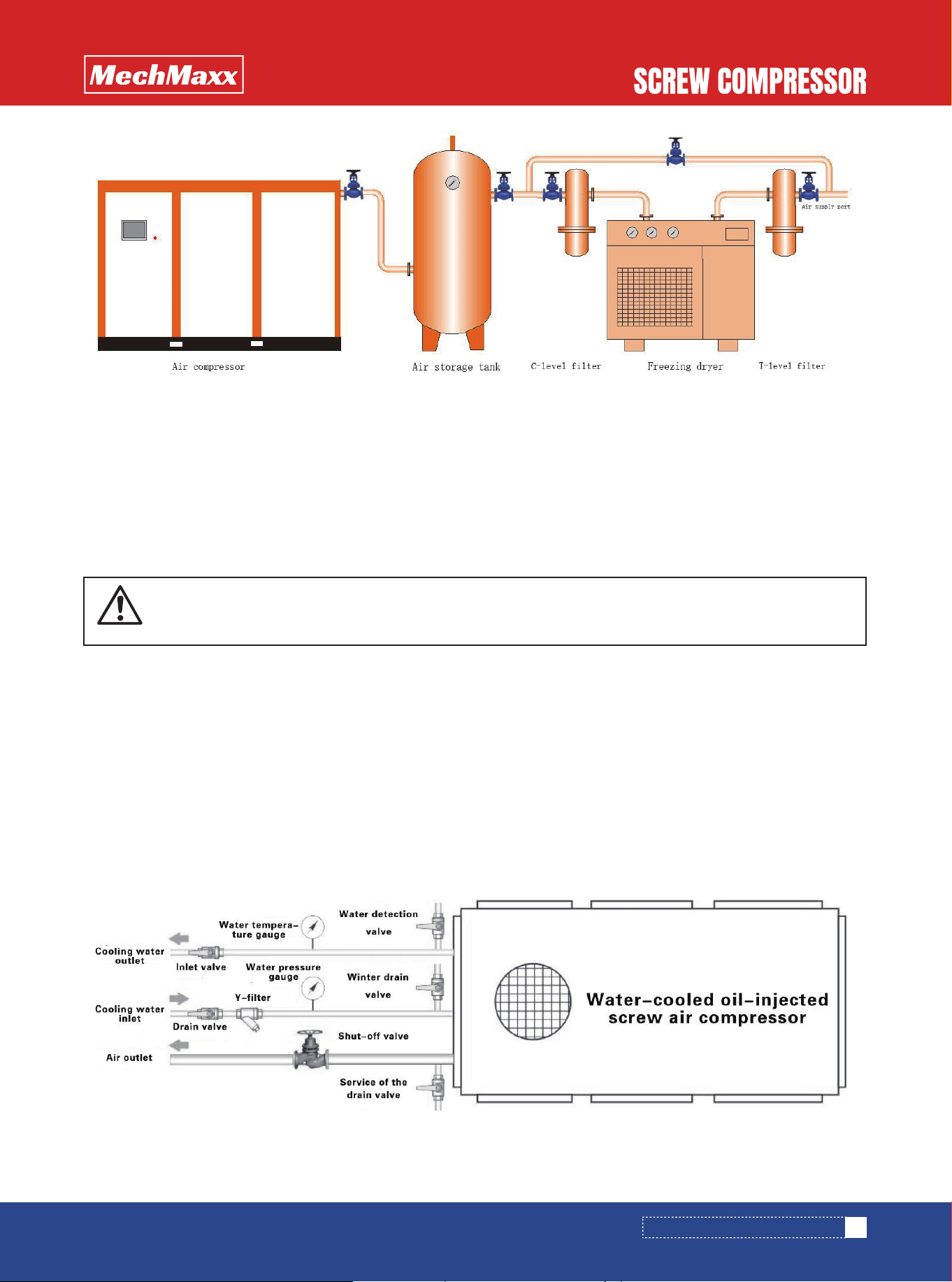
2.3.2.7 If there are air storage tanks and dryers after the
air compressor machine, the best piping order is air
compressor+air storage tank+dryer.
2.3.2 Pipe installation
2.3.2.1 When piping the main pipeline, the pipeline must
have an inclination of 1 ° to 2 °. It is conducive to the
discharge of condensed water in the pipeline.
WARNING
The oil and water leaked from the machine
should be collected and submitted to the
environmental protection department for
treatment to prevent environmental pollu-
tion.
INSTALLATION OF AIR COMPRESSOR
11
www.mechmaxx.com
2.3.3 Cooling system installation
2.3.3.1Installation of air-cooled cooling system
(1)The air-cooled screw air compressor should be installed in a well ventilated machine room, and installed with an
air guide hood to guide the heat generated by the air-cooled cooler to the outside.
(2)Install an air source near the air compressor to regularly clean the cooling fins of the air-cooled cooler.Regularly
clean the air-cooled cooler to prevent the machine from shutting down at high temperatures.
2.3.3.2 Water-cooled cooling system
(1) The cooling water of the air compressor should comply with the provisions of industrial water to avoid the calcium and
magnesium plasma in the water from causing chemical reactions due to high temperature, in the cooler
Scale builds, affecting the efficiency of the cooler. The cooling water quality should comply with the following regulations:
• The content of suspended solids should not be greater than 100mg/L;
• The PH value shall not be less than 6.5, and should not be greater than 9;
• Thermally stable
(2)The cooling water system of the air compressor should be used separately, if the cooling water tower circulation
system is used, the cooling water tower should comply with the cooling water specified by the air compressor volume,
while the selection of pump power should be correct.
(3) The water pressure of cooling but water must generally be maintained between 21.7~65 PSI; The cooling water outlet
temperature should be kept below 104℉.
(4) Cooling water consumption of water-cooled air compressor:
Figure 2-1 Air compressor+air storage tank+dryer system
BE CAREFUL
The installation of the wind guide cover should prevent outdoor dust and rain from pouring back
into the cooler of the air compressor.
12
www.mechmaxx.com
INSTALLATION OF AIR COMPRESSOR
(5) Regularly clean the scale in the radiator copper tube
to maintain efficient heat dissipation.
2.4.1 Selection and installation of circuit breakers
(1)The circuit breaker is mainly used to cut off the
main power supply of the air compressor and protect the
motor.
Select an appropriate circuit breaker based on the rated
current of the host motor. The circuit breaker must have a
motor overcurrent protection function.
(2)The circuit breaker must be a motor protected
circuit breaker with an instantaneous action setting of
8-15 times the rated current of the motor. Please avoid
using a power distribution type circuit breaker, and
choose a power distribution type circuit breaker. The
circuit breaker may malfunction when the motor is start-
ed.For inverter screw air compressors, avoid using circuit
breakers with leakage protection.
(3)The circuit breaker should be installed next to the
air compressor machine to facilitate maintenance of the
air compressor. The installation of circuit breakers should
comply with corresponding safety regulations.
2.4.2 Selection and installation of cables
Select the appropriate cable based on the rated voltage
and current of the air compressor, and determine it based
on factors such as environmental conditions, laying meth-
ods, and product technical data. The type selection and
installation shall generally be considered according to the
following principles:
(1)Cables should be laid underground or through
buried pipes as much as possible to reduce the damage
caused by external pressure on the cables. Plastic
sheathed cables shall be laid in pipes.
(2)The low-voltage power cable shall be a four-core
power cable, and the sheath method of the cable shall be
selected according to the laying method.
(3)The cable cross-section should be appropriately
increased when the ambient temperature is high, and the
cross-section must also be increased to reduce voltage
drop when the laying distance is long.
2.4.3 Power Requirements
The user's incoming power supply should be consistent
with the rated voltage and frequency of the air compres-
sor.
Power supply voltage requirements:
(1)The voltage fluctuation should not be too large, and
the voltage fluctuation should be between - 10%
and+10% of the rated voltage of the motor.
(2)The voltage imbalance should meet the standard,
and the three-phase imbalance of the three-phase power
supply voltage should not exceed 5%. If the fluctuation is
too large, a voltage stabilizer must be installed or the
power grid must be rectified.
(3)The capacity of the power grid meets the starting
requirements of the motor, otherwise it will be difficult to
start the motor, and even cause the circuit breaker to trip.
(4)It is best to use a separate power system for the
air compressor to facilitate maintenance.
2.4.4 Grounding requirements
The body and motor housing of the air compressor should
be reliably grounded to prevent static electricity from
causing a fire in the oil gas separator and causing hazards
due to electrical leakage.
The body and motor housing of the air compressor are
connected to the grounding body through yellow and
green dual color PE grounding wires or galvanized round
steel (flat steel), with a cross-section meeting relevant
requirements.
ELECTRICAL INSTALLATION
DANGER
Do not use cables with too small cross
sections, otherwise the cables are prone
to danger due to high temperatures;
Do not use cables with voltage that does
not meet the requirements, otherwise
serious accidents such as fire and electric
shock may occur.
DANGER
Do not use high-voltage power supplies
on low-voltage equipment, otherwise the
equipment may burn down and cause
personal injury.
Horse
Power
75
100
120
150
175
200
250
300
350
380
420
100 140 180 220 260
HP
2.5.1 Cable connection from user power supply to air
compressor control cabinet
Air compressor control cabinet uses three-phase AC
power supply AC230V/460V (~3 × L+PE), see Table 1-1
for connecting cables. The user power supply is connect-
ed to the R, S, and T terminals of the frequency converter
via a circuit breaker.
2.5.2 Ground wire connection
Connect the grounding terminal of the air compressor to
the grounding body with yellow and green dual color PE
wire. After grounding, use a grounding resistance measur-
ing instrument to measure the grounding resistance,
which should be less than 4 ohms.
ELECTRICAL CONNECTIONS
BE CAREFUL
The wiring work shall be completed by
electricians with electrician certificates.
Failure to heed warnings may result in
electric shock accidents or damage to
equipment.
BE CAREFUL
The cable connection must be firm and
not loose, otherwise it may cause the
cable to heat up, burn components, or
even cause a fire.
DANGER
Unreliable grounding or non grounding
may cause serious accidents such as fire
and electric shock.
It is strictly prohibited to use gas pipe-
lines and water pipelines as grounding
bodies. Otherwise, accidents may occur.
It is prohibited to connect the three-phase
power supply zero line to the air compres-
sor casing or grounding body, otherwise
causing equipment failure.
13
www.mechmaxx.com
INSTALLATION OF AIR COMPRESSOR
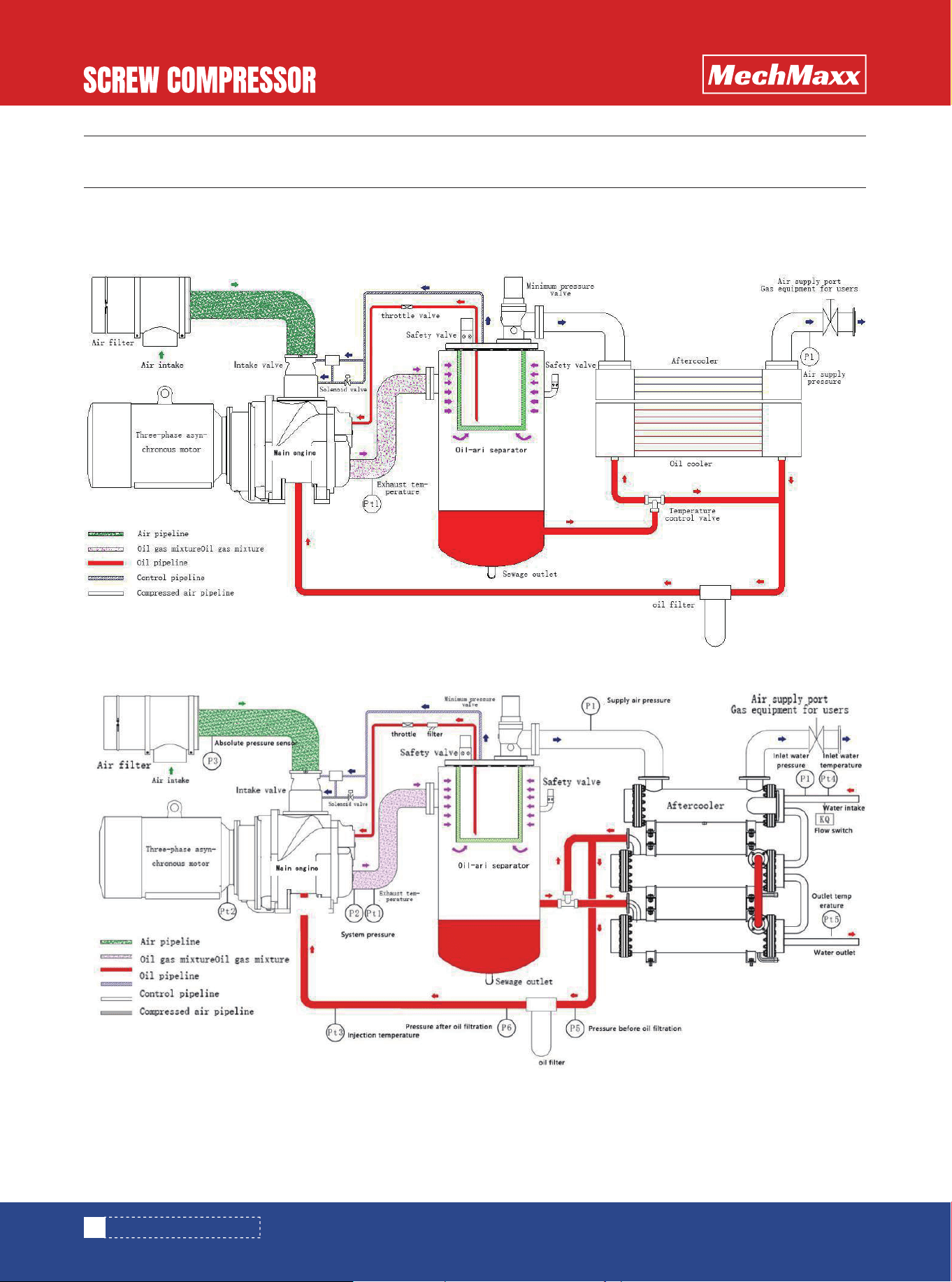
The system flow diagram of the air compressor is shown in Figure 3-1
Figure 3-1 System Flow Chart
3.2 Water-cooled air compressor system flow chart
SYSTEM FLOW DIAGRAM
AIR COMPRESSOR SYSTEM
14
www.mechmaxx.com
AIR COMPRESSOR SYSTEM
15
www.mechmaxx.com
The air circuit system consists of an air filter, an intake
valve, a main engine, an oil gas separator, a minimum
pressure valve, an aftercooler, and a gas pipe.
After dust removal by the air filter, the air flows through
the intake valve and enters the intake port of the host
machine. The air is compressed inside the host machine
and discharged from the exhaust port of the host
machine, and then enters the oil gas separator through
the exhaust pipe. Oily compressed air is separated by
rotary centrifugation in the upper part of the oil gas
separator, and the lubricating oil is gathered on the cylin-
der wall under the action of centrifugal force to condense
into droplets, which fall into the oil tank. After centrifugal
separation, compressed air enters the filter element in
the oil gas separator for fine separation. The finely sepa-
rated oil accumulates at the bottom of the filter element.
Due to the installation of a return pipe inside the filter
element, the oil at the bottom of the filter element enters
the intake pipe of the host machine through the return
pipe under pressure. The compressed air after two sepa-
rations is very clean. The compressed air flowing from the
oil gas separator is supplied to the user through the
minimum pressure valve and the aftercooler.
The main function of the air filter is to remove dust from
the air, to avoid premature wear of the compressor host
engagement pair, and to prevent clogging of the oil filter
and oil gas separation filter element.。
Generally, the dust on the surface should be removed and
removed every 500 hours by using low-pressure air to
blow the dust away from the inside out. In dusty areas,
the cleaning time should be shortened.
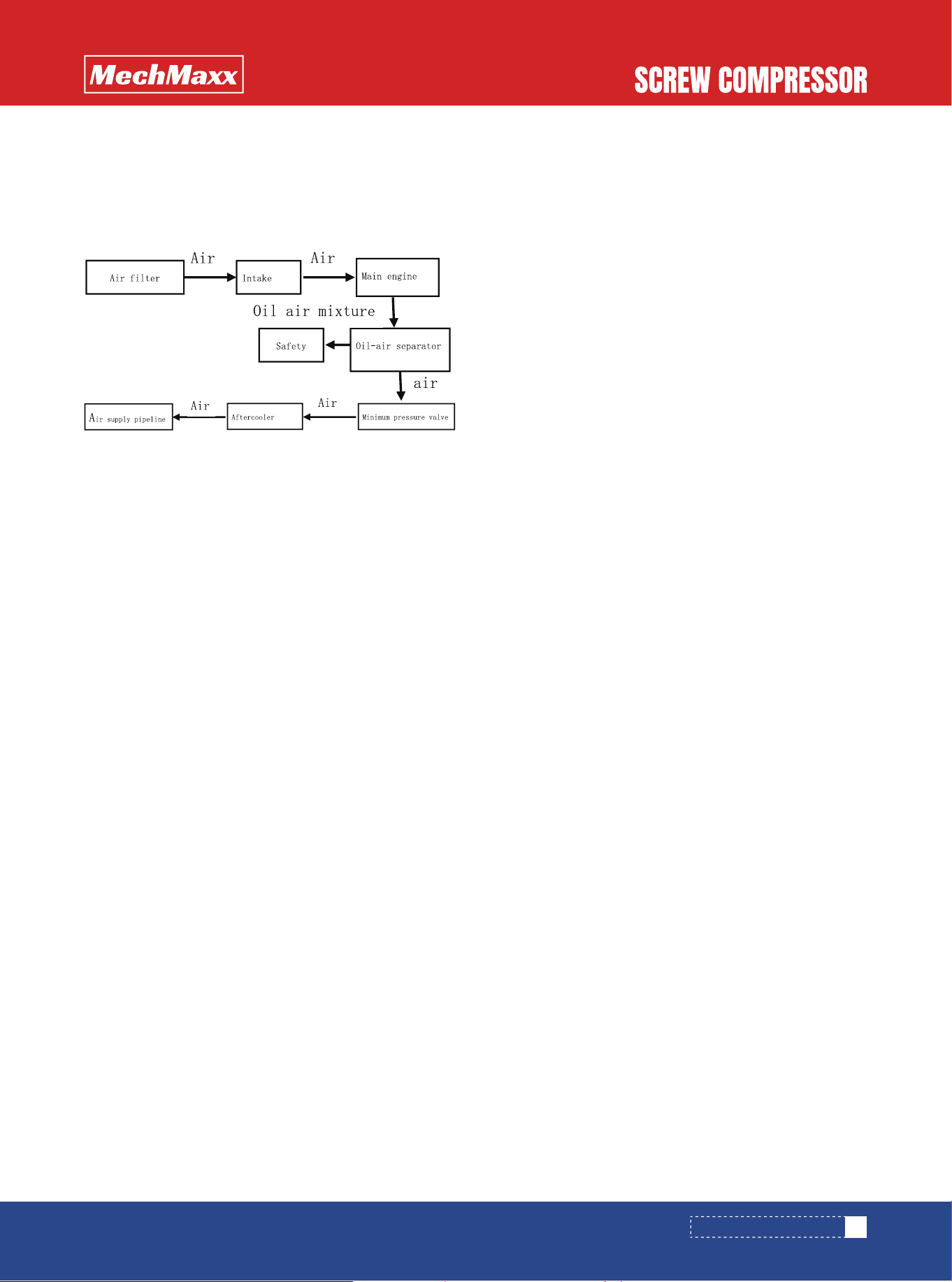
Figure 3-2 Air Path Flow Chart
AIR CIRCUIT SYSTEM
AIR FILTER
The intake valve has two main functions:
(1)When starting and unloading the compressor,
close the intake valve plate to keep the compressor in an
unloaded state, achieving low current starting and
unloading time and load operation;
(2)When the gas consumption changes, balance the
intake air of the compressor with the actual gas
consumption.
The minimum pressure valve is located at the outlet
above the oil gas separator and has the following
functions:
(1)When starting, priority should be given to estab-
lishing the circulation pressure required for lubricating oil
to ensure machine lubrication.
(2)When the pressure exceeds the opening pressure,
the valve opens, which can reduce the air flow rate
through the oil gas separator. In addition to ensuring the
oil gas separation effect, it can also protect the oil gas
separator filter element from damage due to excessive
pressure difference.
(3)Prevent system pressure backflow during empty
vehicle discharge (unloading).
An air-cooled cooler uses a cooling fan to draw in cold air
and cool compressed air through the cooler. Air cooled air
compressors are sensitive to ambient temperature condi-
tions, so it is best to pay attention to the ventilation
conditions of the environment when selecting a place to
place them.
(1)Safety valve:
When the pressure switch is improperly adjusted or fails,
resulting in the pressure at the outlet of the oil-gas
separator exceeding the rated exhaust pressure to a
certain value (for products with a working pressure of
145 PSI or less, the opening pressure of the safety valve
is the rated working pressure+14.5 PSI, and for products
with a working pressure of 145 PSI or more, the opening
pressure of the safety valve is the rated working pressure
× 1.1), the safety valve will jump open to relieve pressure.
INTAKE VALVE
OIL GAS SEPARATOR
AFTERCOOLER
SAFETY AND RELIEF VALVES
AIR COMPRESSOR SYSTEM
(2)Relief valve:
When the oil gas separator filter element has reached its
service life or is clogged, resulting in a large pressure
difference, and the pressure in the oil gas separator has
exceeded a certain value of the rated exhaust pressure
before the safety valve is activated (the opening pressure
of the relief valve is the rated working pressure × 1.2),
the relief valve will jump open to relieve pressure. When
the relief valve operates, the oil gas separation filter
element must be replaced.
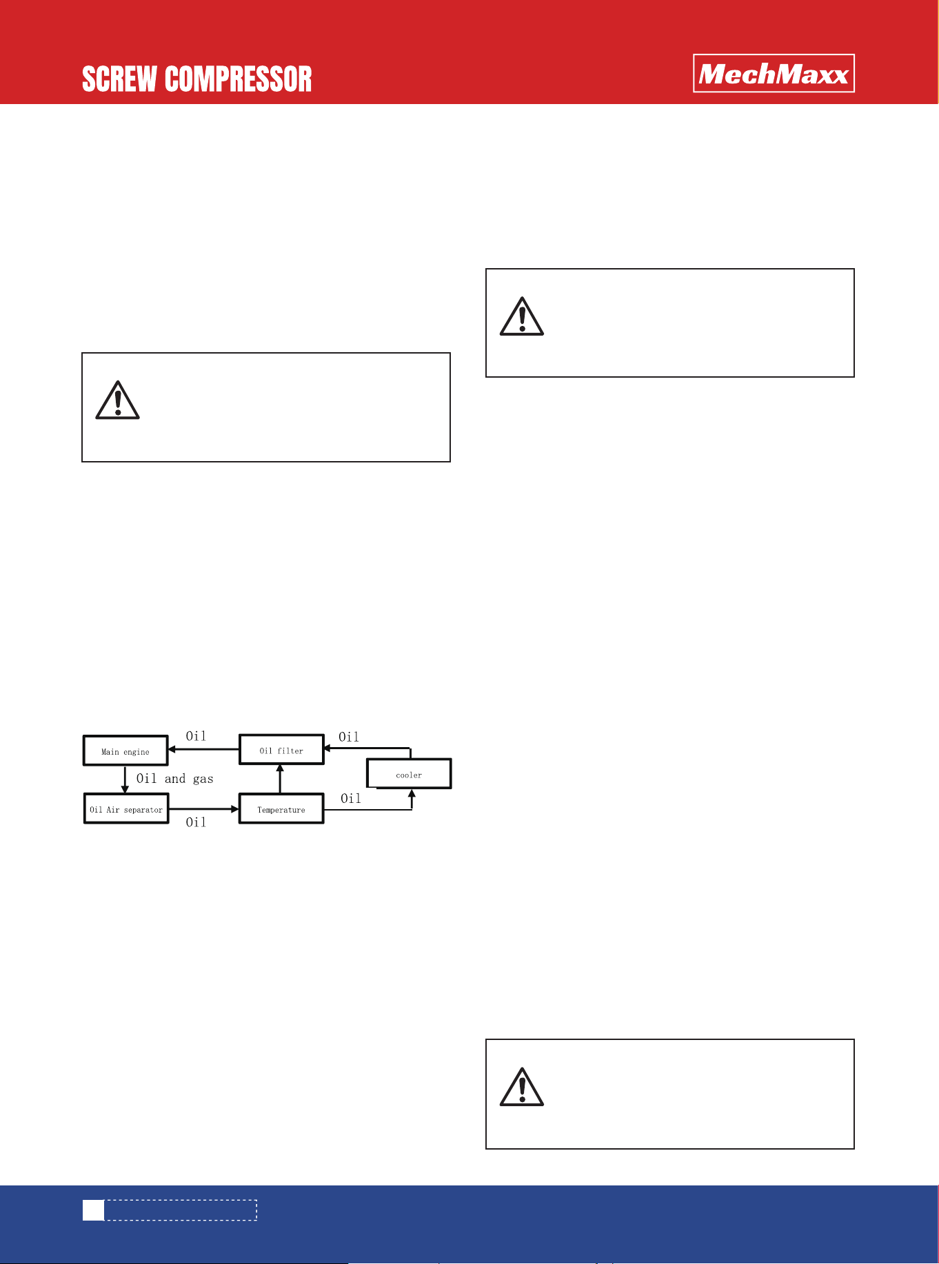
The lubricating oil for screw compressors has four main
functions: lubricating the contact surface between the
bearing and the screw, sealing the gap between the
meshing pairs, cooling the compressed gas, and reducing
noise. The lubricating oil in the oil gas separation filter
element is compressed into the oil cooler by high-pres-
sure gas for cooling, and then enters the compressor
after being cleaned of dirt and impurities through the oil
filter. (Machines 75 kW and below are not equipped with
temperature control valves)
The oil filter is a paper-based filter whose function is to
remove impurities in the oil, such as worn metal particles,
dust, oil compounds, etc. The filtering accuracy is
between 10u and 15u, providing perfect protection for
bearings and screws. The first time the new machine runs
for about 500 hours, the oil and oil filter need to be
replaced. Afterwards, they will be replaced according to
the oil filter timing or pressure difference fault alarm
indication. If the oil filter has a large differential pressure
and is not replaced, it may lead to insufficient oil intake,
causing a high temperature trip, and at the same time,
insufficient oil may affect the bearing life.
The fins of the air-cooled air compressor oil cooler are
covered with dust, which affects the cooling effect. The
exhaust temperature may be too high, resulting in a trip.
Therefore, it is necessary to regularly blow off the dust on
the surface of the fins with compressed air.
The function of the temperature control valve is to main-
tain the exhaust temperature above the pressure dew
point temperature. When starting up, the lubricating oil
temperature is low, and at this time, the bypass ports of
the temperature control valve are all open, and the oil
enters the engine body without passing through the oil
cooler. If the oil temperature rises above 140℉, the valve
slowly closes the bypass port. When the temperature
reaches 158℉, the bypass port is fully closed, and at this
time, all the oil passes through the oil cooler before enter-
ing the engine.
The oil gas separator has two functions: oil storage and
oil gas separation. An oil level gauge is installed on the
side, and the lubricating oil pointer should be located in
the middle of the upper and lower scale lines of the oil
level gauge during operation. The lower part of the tank
has an oil filler for refueling. An oil drain valve is installed
at the bottom of the oil gas separator. In wet seasons,
slightly open the oil drain valve before starting every day
to drain condensed water from the bottom of the oil gas
separator. The mist like oil and gas contained in the
compressed air can be almost completely filtered out
through the oil gas separator filter element, with an oil
content of less than 3 ppm. The oil filtered by the oil-gas
separation filter element is concentrated at the bottom
of the filter element. Then, it flows back to the engine
body through the filter, orifice, and oil mirror through the
oil return pipe.
Figure 3-3 Lubricating Oil Circuit Flow
LUBRICATING OIL SYSTEM
OIL FILTER
OIL COOLER
TEMPERATURE CONTROL VALVE
OIL GAS SEPARATOR
BE CAREFUL
In winter, in areas where the normal
temperature is below the freezing point,
the cooling water in the cooler must be
drained after the machine is shut down。
WARNING
The safety valve and relief valve have
been adjusted before leaving the factory.
Please do not adjust them randomly and
send them for regular inspection.
WARNING
The company does not recommend users
to choose other brands of lubricating oil,
as using unqualified oil will damage the
air compressor.
16
www.mechmaxx.com
AIR COMPRESSOR SYSTEM
This equipment is equipped with safety warning prompts,
safety protection systems, and alarm devices to prevent
machine damage or personal injury due to human opera-
tions, mechanical failures, and electrical failures. For your
safety, please be sure to follow any safety instructions on
the machine and in the user manual.
Safety warning labels and usage reminder labels are
posted on the body or components of the air compressor
to guide the operation and maintenance of the equipment.
Please strictly follow the precautions on the label when
operating or maintaining the air compressor to ensure
safe and reliable operation.
This user manual also contains safety instructions and
safety warnings. Please carefully read and understand
them, and strictly abide by them during the use of the
equipment.
1)Remove the transportation fixing label: Paste it next
to the main engine and motor transportation fixing bolts
to be removed, with the arrow pointing towards the trans-
portation fixing bolt. When the unit is started up and
running, the transportation fixing bolts and transportation
fixing seats (racks) here should be removed and properly
stored. During the next transportation, the bolts and
transportation fixing seats (racks) should be installed
and locked tightly.Failure to heed this warning may result
in compressor host and pipeline failures.
(2)Warning and Maintenance Plan Label: Please
carefully read and strictly implement the corresponding
contents and operations to ensure that the machine
operates in the optimal state.
(3)Determine the steering label (warning level):
Please refer to Section 4.1.2.
(4)Do not use it as a respiratory label (hazard level): It
is strictly prohibited to use compressed air directly for
breathing. Compressed air should be treated with
dedicated aftertreatment equipment before being used
for breathing. Otherwise, serious personal injury will
result.
(5)Label (Hazard Level): It is strictly prohibited to use
this machine in flammable and explosive environments.
Electric arcs generated during machine operation can
cause major accidents. Please use an air compressor
with corresponding explosion-proof grade in flammable
and explosive environments. Please consult our company
for sales information.
(6)Use caution label (warning level): The operation
and maintenance of the air compressor requires fixed
professional personnel. Before using the air compressor,
it is necessary to carefully read the operating instruc-
tions, strictly follow the instructions for operation and
maintenance, and use original spare parts. Otherwise, the
company cannot fulfill the originally agreed commitment
of free warranty and after-sales service.
(7)Air filter maintenance label (warning level): Regu-
larly clean the air filter to keep the machine running in the
best energy efficient state. During cleaning, the pressure
of compressed air used to clean the filter element should
not exceed 72.5 PSI. Excessive blowing pressure may
damage the filter element.
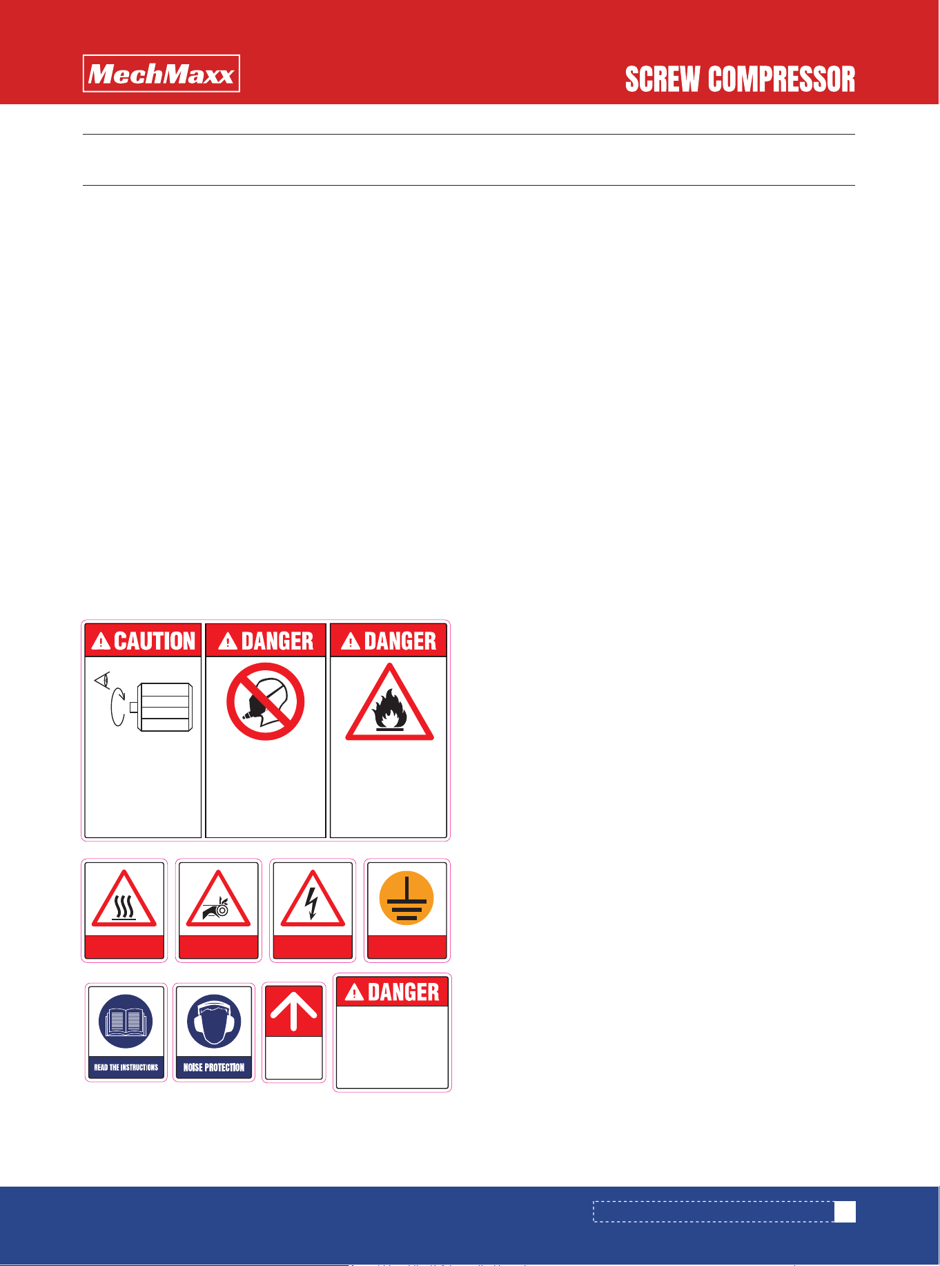
Figure 4-1 Safety Warning Label
SAFETY WARNINGS AND TIPS
SAFETY WARNING LABEL
SECURITY PROTECTION AND ALARM SYSTEM
17
www.mechmaxx.com
Before loosening or
removing the oil plug,
make sure that the oil
and gas separator
pressure gauge reads
0 Mpa.
It is forbidden to use this
machine in places where
flammable or explosive
gases are present.
Otherwise, the arc
generated by the unit will
cause a fire, resulting in
personal injury or property
damage!
Directly using compressed
air for breathing may result
in serious personal injury.
It is strictly forbidden to use
compressed air in a
confined space under
construction.
When running for the first
time or when the power cord
is changed, make sure that
the rotation of the compressor
motor and the cooling fan is in
the direction indicated by the
arrow.
Compressor reversal will
cause severe head failure.
HIGH TEMPERATURE
CAUTION
MECHANICAL INJURY
DANGER! ELECTRIC
GROUNDING
Be sure to remove
the red shipping
anchor bolt and
anchor frame
before starting up.
SECURITY PROTECTION AND ALARM SYSTEM
(8)Full pressure relief warning label (hazard level):
When disassembling pressure bearing components, the
residual pressure inside the machine may eject the
pressure bearing components, causing personal injury.
When disassembling pressure bearing components, it is
necessary to confirm that the pressure in the oil gas
separator is zero.
(9)Pay attention to the high temperature label (warn-
ing level): the temperature of the exhaust outlet pipeline
of the host and the surface of the oil-gas separator is
high. Please do not touch the corresponding parts to
avoid scalding.
(10)Beware of hand clamping (danger level): paste it
near the rotating parts (host motor coupling, fan rotating
parts). Do not touch the corresponding parts or prohibit
operation nearby. Be careful not to get involved, which
may lead to machine failure or serious personal injury.
(11)Electrical hazard label (hazard level): Posted on
the electrical box door and electrical insulation partition.
When opening the electrical box door or removing the
electrical insulation partition, please cut off the incoming
power supply to prevent electric shock.
(12)Be sure to place a grounding label (warning level)
near the grounding point. Please connect the air compres-
sor to a reliable grounding body in accordance with the
relevant electrical specifications. Do not use gas
pipelines or water pipelines as grounding devices, as this
may cause serious accidents.Unreliable grounding may
cause electrostatic ignition or electric shock accidents in
the oil gas separator filter element.
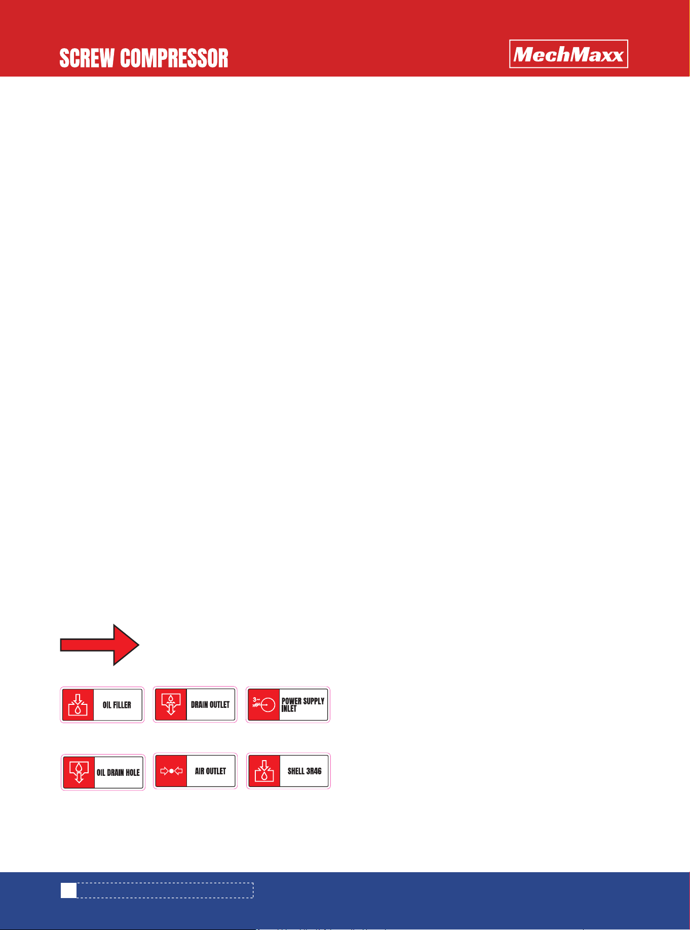
Figure 4-2 Reminder Label
(1)Motor steering label: used to determine whether
the motor's steering is consistent with this label.
(2)Oil inlet label: posted near the oil inlet of the oil gas
separator, indicating that this is the compressor oil inlet.
(3)Sewage outlet label: posted at the outlet position
of the air compressor water distributor, indicating that
the outlet is a sewage outlet. (Applicable to some
models)
(4)Power supply inlet label: posted at the external
inlet of the air compressor, indicating that the inlet is
power supply inlet.
(5)Oil outlet label: posted at the position of the oil
outlet at the lower end of the oil gas separator, indicating
that the outlet is an oil outlet. When not using this oil
outlet, please plug it with a plug.
(6)Air outlet label: posted at the exhaust port of the
air compressor, indicating that the port is an air outlet.
The electrical control system of the air compressor is
equipped with fault and alarm self-diagnosis functions.
When an abnormality occurs in the air compressor, the
electrical control system of the air compressor will
promptly diagnose and safely protect the shutdown or
issue an alarm signal.
The fault and alarm self-diagnosis function of the air
compressor is divided into heavy faults and light faults.
Any fault that causes the machine to shut down becomes
a serious fault. When a serious fault occurs, the machine
stops and locks, and the control panel displays fault
information or codes.
Reverse rotation of the air compressor can cause serious
damage to the compressor. In order to prevent the
compressor from reversing, the controller has a phase
sequence protection function. When the controller
displays a phase sequence error, switch any two phases
of the motor feed line.
REMINDER LABEL
SECURITY PROTECTION SYSTEM AND
ALARM DEVICE
AIR COMPRESSOR ANTI REVERSE
PROTECTION
18
www.mechmaxx.com
Direction of Rotation
1.
2.
3.
4.
5.
6. 7.
SECURITY PROTECTION AND ALARM SYSTEM
The reasons for motor protection shutdown include:
(1)Due to human operation reasons, such as self
adjustment of loading and unloading pressure, incorrect
adjustment of system parameters, frequent use of emer-
gency shutdowns, unstable wiring, and untimely mainte-
nance.
(2)Mechanical faults, such as internal loss of the
motor, stuck motor bearings, non action of the safety
valve, unclosed intake valve, excessive lubricating oil in
the main engine, etc.
(3)Electrical faults, such as low power supply voltage,
high current caused by loose cable joints, motor out of
phase operation, motor winding faults, etc.
The set temperature for overtemperature warning of
compressors with a rated pressure of 43.5 PSI~145PSI is
221℉. When the exhaust temperature exceeds this set
value, the alarm will not stop; When the exhaust tempera-
ture exceeds 230℉, an over temperature alarm will be
triggered and the machine will shut down.
The set temperature for overtemperature warning of
compressors with a rated pressure of 181 PSI to 232 PSI
is 239℉. When the exhaust temperature exceeds this
set value, the alarm will not stop; When the exhaust
temperature exceeds 248℉, an over temperature alarm
will be triggered and the machine will shut down.
There are many reasons for high exhaust temperature,
mainly:
(1)The fins of the air-cooled cooler are covered with
dust.
(2)The oil filter is blocked.
(3)The ambient temperature in the air compressor
room is too high and the ventilation is not smooth.
(4)The lubricating oil level of the oil gas separator is
too low.
The ambient temperature is too low, the lubricating oil
thickens, and it is difficult to start the machine; The
phenomenon of "ice blockage" is prone to occur in the oil
and gas separator, and forcibly starting the machine can
easily cause serious faults. When the ambient tempera-
ture is below 0 ℉, the unit cannot start.
After installing the minimum pressure valve, the air
compressor is equipped with a pressure transmitter that
displays the exhaust pressure of the machine. In addition,
the microcomputer controller is equipped with an
overpressure protection function. When the exhaust
pressure exceeds the rated pressure of the machine
by+7.2 PSI, the machine will report an exhaust overpres-
sure shutdown. This action occurs before the action of
the safety valve and relief valve.
PROTECTION AGAINST EXCESSIVE
EXHAUST TEMPERATURE
PROTECTION AGAINST LOW AMBIENT
TEMPERATURE
HIGH EXHAUST PRESSURE PROTECTION
WARNING
When debugging a new machine or chang-
ing the incoming power supply, even if the
controller does not display a phase
sequence error, it is necessary to jog the
air compressor to determine whether the
motor direction is consistent with the
marked direction.
WARNING
The air compressor must be started at an
ambient temperature above 0 ℉. In areas
with ambient temperatures below 0 ℉,
the oil drain valve should be opened
before each cold start of the machine to
confirm that there is no "ice blockage" in
the oil gas separator.
19
www.mechmaxx.com
BE CAREFUL
For machines equipped with frequency
converters, the rotation of the motor is not
affected by the phase sequence of the
incoming power supply.For frequency
converters, changes in the phase
sequence of the three-phase incoming
power supply cannot change the direction
of the motor's rotation.To change the
direction of the motor, it is necessary to
exchange any two phases of the
three-phase wires at the output end of the
frequency converter (connected to the
motor).
SECURITY PROTECTION AND ALARM SYSTEM
After an alarm occurs, an alarm that does not affect the
normal operation of the unit in the short term becomes a
minor fault. When a minor fault occurs, the unit does not
shut down.
When the service life of lubricating oil, motor lubricating
grease, air filter, oil filter, and oil gas separation filter
element reaches the prompt, the user should replace the
three filters and lubricating oil, and add motor lubricating
grease.
The air compressor oil gas separator filter element is
equipped with a relief valve in front of it, and the oil gas
separator cover is equipped with a safety valve.
LIGHT FAULT PROMPT FUNCTION
LUBRICATING OIL AND WEAR PARTS
SERVICE LIFE ALARM PROMPT
MECHANICAL PROTECTION OF THE
MACHINE
WARNING
After a minor malfunction occurs, please
promptly notify maintenance personnel to
maintain the air compressor. Long term
failure to handle may affect the perfor-
mance of the unit and even lead to the
occurrence of serious faults.
20
www.mechmaxx.com
SECURITY PROTECTION AND ALARM SYSTEM
OPERATION OF THE AIR COMPRESSOR
Although each screw compressor has undergone testing
before leaving the factory and strict inspection before
shipment, it cannot be guaranteed that there will be no
damage during transportation. Therefore, before debug-
ging, each compressor should be rechecked for damage,
and the transportation fixing bolts and transportation
fixing seats (frames) should be removed to check wheth-
er the red lines of the moving component bolts are consis-
tent. In addition, during the first few hours of operation,
attention should be paid to observing the operation of the
machine. The screw compressor is fully assembled before
leaving the factory and can be directly connected to the
compressed air main using a flexible joint.
(1)Check whether the pipeline joints, instruments,
circuit connection joints, etc. are loose or detached due
to transportation, installation, etc. If any, please tighten
it in a timely manner. Confirm that the exhaust valve is
open.
(2)Check if the air filter element and oil filter are
loose, and if so, tighten them in a timely manner.
(3)Please make sure that the power supply voltage
fluctuation range is within ±10% of the rated voltage
(230V/460V).
(4)Confirm that an independent circuit breaker is
installed for the air compressor, and the capacity of the
circuit breaker should be selected according to the
requirements of this manual.
(5)Check whether all wiring in the electrical box is
loose, and if so, please tighten it in time.Use a screw-
driver or wrench to check and tighten the wiring of the
main circuit and the control circuit of the AC contactor.
(1)Within 1-2 seconds after pressing the start button
on the touch screen, immediately press the "Emergency
Stop" button to check if the steering is correct (as
indicated by the arrow direction). If the steering is incor-
rect, please switch any two phases of the three-phase
wire at the output end of the frequency converter
(connected to the motor) to check if the fan steering is
correct.
(6)Check if the components inside the electrical box
are damaged and if the wires are damaged. If available,
please contact our company's after-sales service.
(7)Check whether the oil level in the oil and gas
separator is within the safety line. If not, please add the
appropriate amount of lubricating oil. If the oil level is very
low, please check whether the blowdown valve is open, or
the pipeline is loose and leaking oil.(8)Check the
cooling system for damage or damage.
(8)Check the safety valve and relief valve for damage.
(9)If the trial operation is only carried out after a long
time of delivery or if the shutdown time exceeds three
months before use, approximate lubricating oil should be
added to the intake valve and the air compressor should
be turned several times by hand to prevent oil shortage
and burning in the compressor host during start-up.
(10)According to the safety warning label (1) shown
in item 4.1.1 (this warning label is posted on the base
near the motor and the host in a prominent position),
remove the host and the motor transportation fixed
column (frame). It is recommended to retain the removed
main engine, motor transportation fixed frame, and
fasteners for use during long-distance transportation
(11)Check the cooling system.
CHECK AND TEST RUN BEFORE STARTING
THE MACHINE FOR THE FIRST TIME
CHECK BEFORE STARTING THE MACHINE
FOR THE FIRST TIME
TEST RUN
WARNING
(1)Before operating the machine, the
main engine support seat and motor
transportation fixing bracket must be
removed, otherwise it may damage the
compressor main engine.
(2)Before long-distance transporta-
tion, it is necessary to install the main
engine support seat and motor transpor-
tation fixing frame to protect the main
engine and compressor system.
21
www.mechmaxx.com
BE CAREFUL
The first start-up of a new air compressor
after installation, or the first start-up after
transportation to another location, must
undergo pre start-up inspection and trial
operation.
OPERATION OF THE AIR COMPRESSOR
(2)After resetting the emergency stop button, press
the start button and the air compressor will start running.
(3)Observe if there are any abnormal indications on
the display screen; Can the machine load normally; Is
there any abnormal vibration in the air compressor. If
there is any abnormal sound, vibration, water leakage, oil
leakage or other abnormal phenomena, immediately press
the stop button, and check after stopping the machine.
(4)Observe whether the motor speed changes when
the exhaust pressure rises to the variable frequency
pressure setting. When the pressure reaches the sleep
pressure, can the machine sleep normally. When the
pressure drops to the sleep start pressure, can the
machine start and operate normally.
(5)Press the stop button to check if the machine
stops normally.
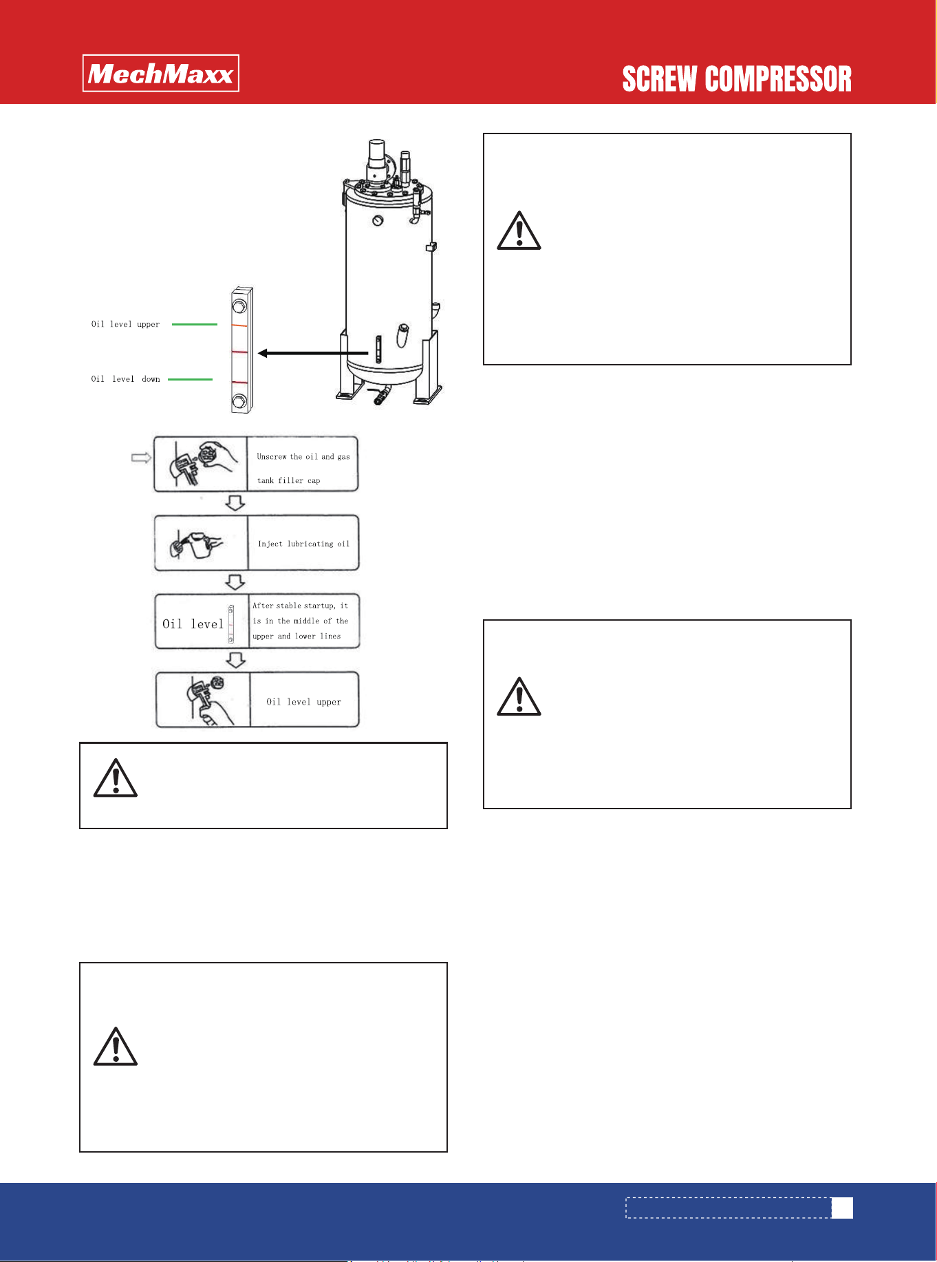
(2)Observe the oil level to ensure that the lubricating
oil level should be in the middle of the upper and lower
scale lines of the oil level gauge when the machine is
running. If the lubricating oil is too much, the machine
should be closed first, and then the oil drain valve can be
opened to discharge a part of the oil; If the lubricating oil
is insufficient, stop and press the emergency stop button
first, and then open the upper oil cap to refuel.The method
of injecting lubricating oil into the air compressor (as
shown in Figure 5-2)::
Figure 5-1
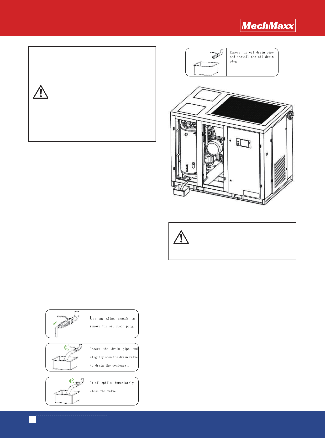
(1)Slightly open the drain valve at the bottom of the
oil gas separator to drain the condensate inside, and then
tighten it again. Condensate discharge method: as shown
in Figure 5-1.
INSPECTION BEFORE STARTUP
22
www.mechmaxx.com
BE CAREFUL
For machines equipped with frequency
converters, the rotation of the motor is not
affected by the phase sequence of the
incoming power supply.The change in
phase sequence of the variable frequency
machine, i.e. the three-phase incoming
power supply, cannot change the direction
of the motor.To change the direction of
the motor, it is necessary to exchange any
two phases of the three-phase wires at the
output end of the frequency converter
(connected to the motor).
BE CAREFUL
Before discharging condensate, it is
necessary to ensure that the pressure
inside the system is zero before proceed-
ing.
OPERATION OF THE AIR COMPRESSOR
(3)Rotate the coupling between the host and the
motor by hand, and it should move freely. If there is any
jamming, it should be checked before starting.
(4)Turn on the main power supply, open the shut-off
valve, and confirm that the pressure in the system is zero.
5.3.1 This compressor has a high degree of automation
and complete safety protection functions, generally
without the need for personnel to take care of it.
5.3.2 When there is abnormal sound, vibration, air
leakage, oil leakage, etc. during operation, the machine
should be immediately shut down.
5.3.3 Check every two hours during operation, record
voltage, current, air pressure, exhaust temperature, oil
level, etc. for future maintenance reference.
5.4.1 Press the stop button to automatically complete
the entire shutdown program for the compressor
machine. The time for complete shutdown will vary
depending on the state of the compressor unit at that
time, but the maximum time will not exceed half a minute.
5.4.2 Turn off the shut-off valve and the main power
supply.
5.4.3 In case of emergency, the emergency stop button
can be pressed to stop the machine, but it should not be
used under normal circumstances.
STARTING OPERATION
SHUTDOWN
WARNING
During operation, there is high pressure in
both the pipeline and the container. Some
components have high temperatures, and
electrical circuits have high pressure.
Therefore, the machine door should be
tightly closed and the pipeline should not
be loosened or other dangerous opera-
tions should be carried out.
23
www.mechmaxx.com
BE CAREFUL
Before discharging or refueling, it is
necessary to ensure that the pressure
inside the system is zero before entering.
BE CAREFUL
Before starting up, the oil drain valve must
be opened to drain the condensed water
inside the machine. If there is condensed
water inside the machine, it can cause
pollution to the unit. Customers can
determine the appropriate interval for
discharging condensate water based on
local usage.
BE CAREFUL
When the temperature in the area is below
zero degrees Celsius, it is necessary to
ensure that there is no "ice blockage" in
the oil and gas separator before starting
it, otherwise it may cause serious acci-
dents; For these cold regions, the conden-
sate should generally be discharged after
the last shutdown before the temperature
of the oil gas separator has dropped to
zero.
OPERATION OF THE AIR COMPRESSOR
Long term shutdown refers to a shutdown and storage
period of more than three months, including long-term
storage of new machines for more than three months and
long-term storage after operation for more than three
months. To ensure that the machine does not damage the
air compressor during long-term shutdown and can
operate normally and safely when resuming operation.
(1)To prevent the influence of humid gases, strict
packaging should be carried out and desiccants should be
added to keep the relative humidity inside the packaging
below 75%.
(2)If the shutdown does not exceed one year, the
condensate at the bottom of the oil gas separator should
be discharged after a few days of shutdown. If the
shutdown time exceeds one year or more, the lubricating
oil in the machine should be drained completely.
(3)Electrical equipment such as electric motors,
electronic control panels, solenoid valves, etc. should be
wrapped in plastic paper and placed with moisture-proof
agents in high and humid areas to prevent moisture intru-
sion.
(4)The machine should be stored in an environment
free from direct sunlight, dust, corrosive gases, flamma-
ble gases, steam, dripping water, and vibrations.
(1)Remove plastic paper from the machine or electri-
cal equipment.
(2)Measure the insulation resistance of the motor
with a 500V megohmmeter, and each data item should be
greater than or equal to 1 megohm.
(3)For machines with a shutdown time of no more
than one year, the color or amount of lubricating oil should
be checked to see if it meets the start-up requirements.
Machines that have been shut down for more than a year
should be injected with new lubricating oil.
(4)Perform the pre startup inspection and trial run
according to item 5.1 of this manual.
HANDLING METHODS FOR LONG-TERM
SHUTDOWN
HANDLING METHODS FOR LONG-TERM
SHUTDOWN AND STORAGE
REBOOT PROGRAM
WARNING
When using emergency shutdown or
sudden power outage, a large amount of
lubricating oil may flow into the main
engine. If starting again, first jog 2-3
times to allow the lubricating oil to flow
out of the main engine before normal
operation. If the inching method cannot
start the compressor, first turn the engine
for a few turns and feel that the engine
can be easily cranked before starting. If
the engine still cannot be started, open
the side cover of the engine, drain most of
the lubricating oil and add it to the oil gas
separator before running.2. When the
water-cooled air compressor is shut down
in winter, the accumulated water in the
cooler must be drained, otherwise it may
cause the cooler to freeze and crack!
WARNING
Disposal of waste oil: The waste oil
discharged from the air compressor
should be disposed of in accordance with
Chinese or local laws and regulations.
24
www.mechmaxx.com
OPERATION OF THE AIR COMPRESSOR
Maintenance personnel must have a certain level of
knowledge and operational skills in mechatronics, have a
certain understanding of air compressors, and carefully
read all the contents of this manual before maintenance.
6.1.1 Maintenance work must be carried out when the
machine is shut down, the shut-off valve is closed, and
the power supply is cut off.
6.1.2 Before disassembling any pressurized components,
it must be ensured that the pressure inside the system
has decreased to zero.
6.1.3 Some components in the system have high
temperatures during initial shutdown, so be careful to
avoid burns during operation.
6.1.4 After maintenance and repair, it must be confirmed
that there are no tools, parts, rags, etc. left inside the
compressor.
6.3.1 The oil filter should be replaced after the first 500
hours of operation and every 2000 hours of operation or
when changing the lubricating oil thereafter. The replace-
ment cycle should be shortened in dirty environments.
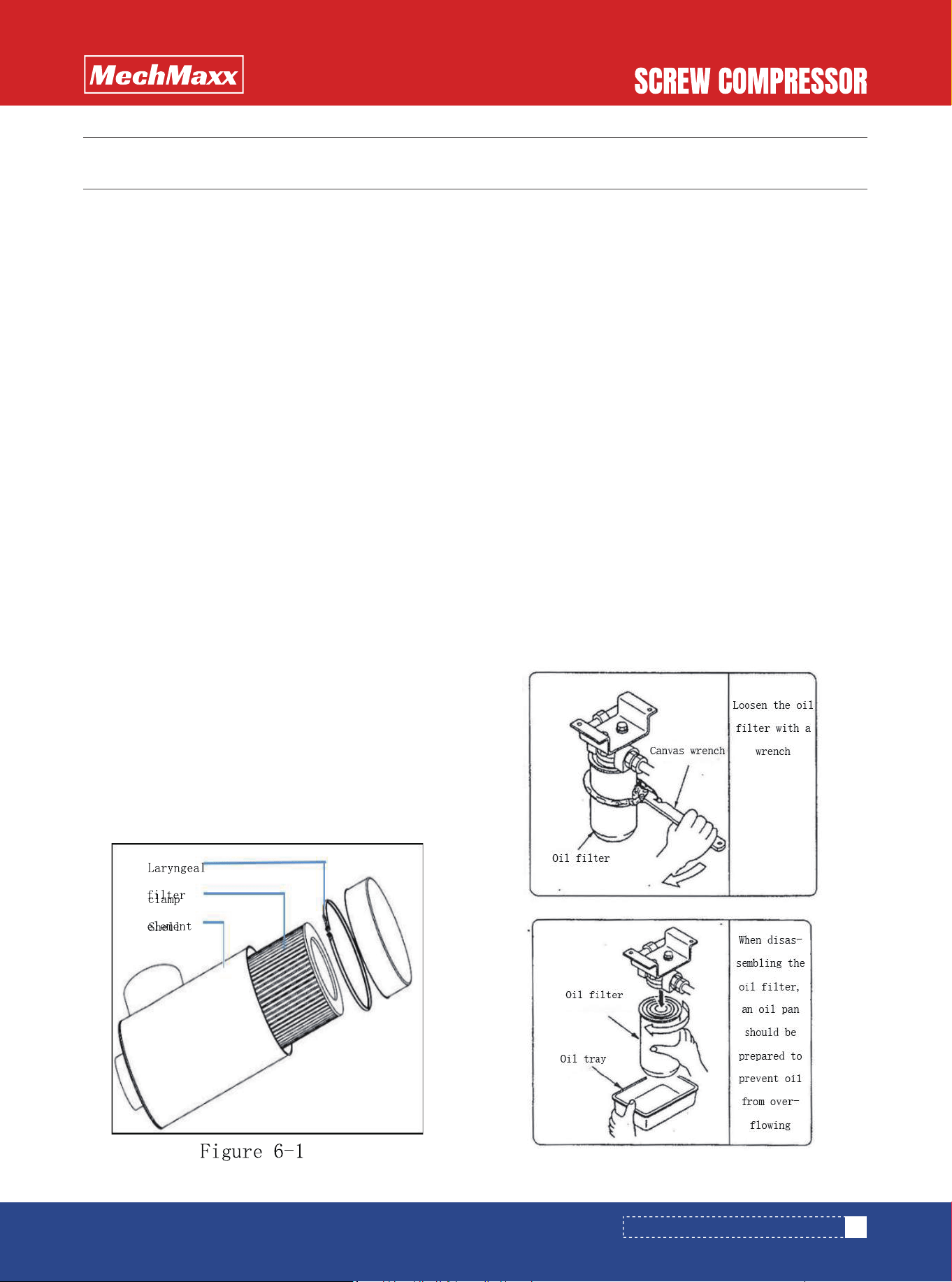
6.3.2 The oil filter alarm indicates that the oil filter is
blocked and should be replaced in a timely manner. The
replacement of the oil filter should be carried out after
shutdown and pressure relief. When replacing, use a
wrench to rotate the oil filter counterclockwise. To
prevent oil from splashing down, prepare a plate to catch
the lubricating oil flowing out. Reinstall the new oil filter,
do not use a wrench during installation, tighten by hand
until the components are in close contact, and then tight-
en by 1/5 turn with the wrench.
6.3.3 Turn on the machine to check for oil leakage. If there
is no oil leakage, it indicates that the replacement is
complete.
6.3.4 An example of oil filter replacement is shown in
Figure 6-2:
The operating conditions determine the maintenance
cycle. The air filter element should be replaced after about
500 hours of use for a new machine. The second replace-
ment time should be set at 2000 hours, and the replace-
ment cycle should be shortened in dusty environments. If
the air filter alarm message is displayed, the air filter
element needs maintenance or replacement.
SAFETY PRECAUTIONS
REPLACEMENT AND MAINTENANCE OF
AIR FILTER ELEMENT
OIL FILTER REPLACEMENT
25
www.mechmaxx.com
MAINTENANCE AND TROUBLESHOOTING
MAINTENANCE AND TROUBLESHOOTING
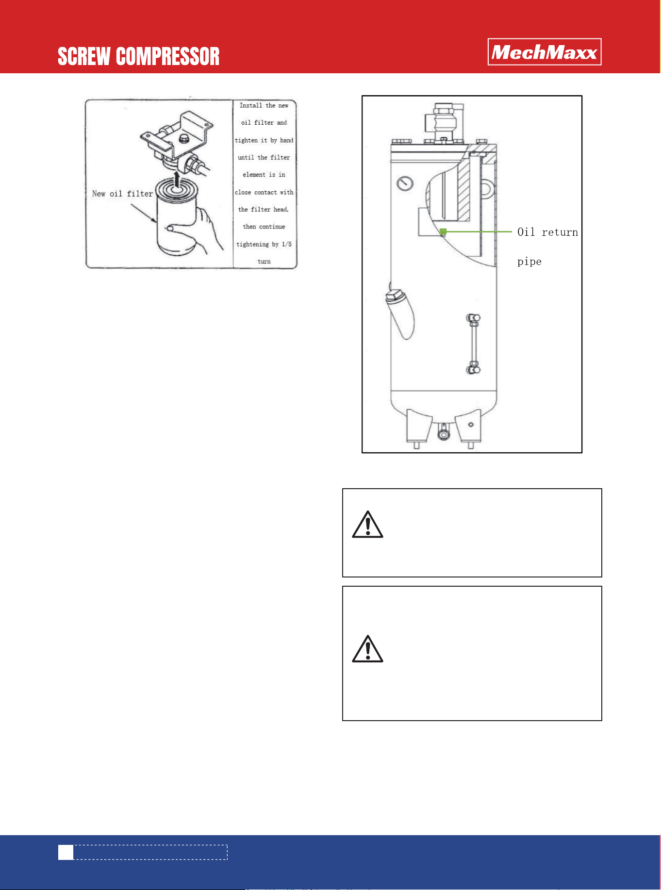
BE CAREFUL
When installing the return oil pipe, the
distance from the bottom of the oil pipe
should not exceed 3mm, otherwise it may
cause excessive oil content in the
exhaust.
The operating conditions determine the maintenance
cycle, and if the environment is poor, the replacement
time should be shortened. The first replacement time of
the new machine is 1500 hours; The second replacement
time is set to 2000 hours. If the timing alarm message of
the oil gas separation filter element is displayed, the filter
element must be replaced.
The replacement steps for the oil gas separation filter
element are as follows:
1. After the air compressor is stopped, close the air outlet
to confirm that the system is not pressurized.
2. Disassemble the pipeline above the oil and gas separa-
tor and at the same time put the outlet of the minimum
pressure valve
The flange bolt is removed.
3. The big machine should be disassembled back into the
oil pipe, and the small machine should directly remove the
cover, without dismantling.
4. Remove the fixing bolt on the upper cover of the oil and
gas separator.
5. Turn the lid bolt to move the upper cover up for a
distance and turn the upper cover (Figure
6-3)。
6. Remove the return tubing. (According to the actual
situation, some machines can be removed directly
without dismantling.)
7. Remove the filter element and replace it with a new
one.
8. Install the oil and gas separator in reverse order of
disassembly.
Figure 6-2
Figure 6-3
OIL GAS SEPARATION FILTER ELEMENT
REPLACEMENT
WARNING
The sealing gasket equipped with the oil
gas separation filter element method has
sealing and anti-static functions. If the
flange surface is replaced, a metal soft
gasket must be installed. If this regulation
is violated, it may cause serious conse-
quences and even burn the entire air com-
pressor.
26
www.mechmaxx.com
MAINTENANCE AND TROUBLESHOOTING
After 500 hours of operation of the new machine, the
lubricating oil alarms in a timed alarm state. The lubricat-
ing oil should be replaced. The second lubricating oil set
life timer alarm time is 2000 hours.
If the air compressor operates in dusty or high tempera-
ture environments, the oil change interval should be
shortened.
6.5.1 The oil change steps are as follows:
6.5.1.1 Confirm that the machine is completely shut
down and confirm that there is no air pressure inside the
oil gas separator. Disconnect the main circuit, mark it,
and disconnect the power supply of the starter.
6.5.1.2 Thoroughly drain the lubricating oil from the
system:
a.Disconnect the low point connection and drain oil from
the pipeline;
b. Drain oil from the oil gas separator drain valve;
c. Pour out the oil from the filter; And reinstall the used oil
filter.
6.5.1.3 Inject 50% new oil into the system:
a. Start the compressor and observe its operation.
b. Run for 5 minutes or until the exhaust temperature
stabilizes, then stop the machine.
6.5.1.4 Thoroughly drain the oil in the air compressor.
6.5.1.5 Replace with a new oil filter.
6.5.1.6 Fill the system with new oil and then reinstall the
fuel filler plug.
To ensure the safe and good operation of the air compres-
sor, please regularly maintain the motor. Please refer to
the motor manual for specific maintenance methods.
Blocking the air inlet of the frequency converter can easily
cause poor heat dissipation, and the frequency converter
is prone to heating, resulting in failure or reduced lifespan
of the frequency converter. To ensure the good operation
of the frequency converter, please regularly maintain the
frequency converter. Please refer to the inverter manual
for specific maintenance methods.
LUBRICATING OIL REPLACEMENT
MOTOR MAINTENANCE
MAINTENANCE OF FREQUENCY CONVERTERS
WARNING
Pressurized air and oil can cause serious
personal injury or death. Before removing
valves, nuts, plugs, installing screws, and
filters, turn off the compressor and
release all pressure in the system, discon-
nect the main circuit, mark it, and discon-
nect the power supply to the starter.
WARNING
Our company does not recommend users
to choose other brands of lubricating oil,
as using unqualified oil will damage the
air compressor.
WARNING
Excessive or insufficient lubricating
grease can cause damage to the motor, so
it is necessary to strictly follow the motor
manual and the motor's greasing name-
plate for greasing.
WARNING
When maintaining the frequency convert-
er, please cut off the incoming power
supply and wait for the charging indicator
light of the frequency converter to turn off
before operating the frequency converter.
Please dispose of lubricating oil in accor-
dance with relevant national or local laws
and regulations. Improper handling of
lubricating oil may cause serious environ-
mental pollution.
DANGER
The compressor, oil gas separator, and all
pipelines during and after operation may
be in a high-temperature state.
27
www.mechmaxx.com
MAINTENANCE AND TROUBLESHOOTING
MAINTENANCE AND REPAIR ITEMS AND MAINTENANCE CYCLE TABLE
WARNING
The content of this table is for users' reference. Customers should change the maintenance cycle
appropriately based on the actual operating environment and performance of the machine.
WARNING
When the air filter element and oil gas separation element are blocked and alarm occurs, they should
be replaced.
28
www.mechmaxx.com
MAINTENANCE AND TROUBLESHOOTING
Everyday
Weekly
Everythree months
Annually
Drain the condensate in the oil gas separator before start-
ing up every day
Check whether the unloading and loading pressure, return
oil sight glass, and return oil are normal
Check the cooler and clean it if necessary
Clean the air filter and frequency converter cooling air duct
Check for oil leaks
Check the oil level before startup and during operation
Check the exhaust temperature of the air compressor
Check if the electrical wiring is securely connected
The first 500 hours of operation of the new machine,
replace the oil filter and lubricating oil
Check the tightness of the oil and gas pipeline connection
Replace lubricating oil
Manual inspection of safety valves (annual inspection)
Replace the air filter element and clean the cooling air duct
of the frequency converter
Replace the oil filter
Check the motor and electrical system
Replace the oil-air separator core, clean the radiator,
Clean the intake valve
Maintenance content
Maintenance intervals
Operating hours
8
500
500
500
500
2000
2000
1000-2000
2000
4000
8

TROUBLESHOOTING TABLE
29
www.mechmaxx.com
1. Unable to
start
2. The
operating
current is
too high,
causing the
motor to
overload
and stop
3.The
exhaust
temperature
is often too
high
1.Electrical personnel inspect the control circuit and
switch it on or replace it.
2.Increase the ambient temperature.
3.Electrical personnel adjust the phase sequence.
4.Electrical personnel maintenance and replacement.
5.Reset the emergency stop button.
6.Electrical personnel maintenance and replacement.
7.Electrical personnel shall maintain and connect firmly.
8.Refer to the instructions and take appropriate
measures.
9.Replace the switch or jumper.
10.Manually rotate the host. If it cannot be rotated,
please contact our customer service center.
11.Electrical personnel maintenance
1. Check the pressure gauge and adjust the pressure
setting.
2. Check the oil number and replace the oil.
3. Replace the oil gas separation filter element.
4. Electrical personnel adjust the power system.
5. Stay away from vibration sources or take vibration
reduction measures.
6. Manually rotate the host. If it cannot be rotated,
please contact our customer service center.
7. Electrical personnel maintenance
1.The small circuit breaker trips or the fuse
blows.
2.The ambient temperature is too low.
3.The phase sequence of the power supply is
reversed.
4.Poor contact of the operation button.
5.The emergency stop button has not been
reset.
6.Motor malfunction.
7.Loose electrical wiring.
8.Read error messages from the touch
screen and frequency converter.
9.Remote contact virtual connection.
10.Host failure.
11.Loose communication line
1. The exhaust pressure is too high.
2. The lubricating oil specification is incor-
rect.
3. The oil gas separation filter element is
blocked and the system pressure is high.
4. Abnormal power supply voltage.
5. There is strong impact vibration nearby.
6. Host failure.
7. Poor contact of circuit contacts.
1. Insufficient or overdue use of lubricating
oil.
2. Insufficient cooling water volume.
3. The ambient temperature is high.
4. The dust filter is blocked.
5. The lubricating oil specification is incor-
rect.
6. The oil filter is blocked.
7. The temperature control valve is faulty.
8. Fan fault
9. The temperature sensor connection wire is
loose.
10. The oil cooler is blocked.
1.Check the pointer of the oil level gauge. During opera-
tion, the lubricating oil pointer should be located in the
middle of the upper and lower scale lines of the oil level
gauge.
2.Check the temperature of the inlet and outlet water
pipes and increase the cooling water flow rate.
3.Check the ventilation of the air compressor room and
increase the air circulation.
4.Cleaning and dust removal.
5.Check the oil number and replace the oil.
6.Replace the oil filter.
7.Repair the temperature control valve core.
8.Electrical personnel repair and replace the fan.
9.Electrical personnel repair or replace corresponding
components.
10.Repair or clean the oil cooler.
Exclusion method
Fault
Cause of occurrence
TROUBLESHOOTING TABLE

TROUBLESHOOTING TABLE (CONTINUED)
30
www.mechmaxx.com
6.Unable to
load
normally
under low
pressure
7. Unable to
automati-
cally unload
and operate
under high
pressure
8. High fuel
consump-
tion
9. High oil
content in
the air
10. The
exhaust
volume of
the
compressor
machine is
lower than
the normal
value
1.Adjust the loading pressure value.
2.Clean the control pipeline.
3.Adjust the discharge flow rate.
4.Repair, adjust, and replace with new products.
5.Replace solenoid valve.
6.Check the leak location and lock it tightly.
7.Replace the intake valve
1.Adjust the unloading pressure value.
2.Replace the intake valve.
3.Clean the control pipeline.
4.Adjust the discharge flow rate.
5.Replace the sealing gasket.
1.The loading pressure value is not set
correctly.
2.The control pipeline is blocked.
3.Leakage pipeline failure.
4.The minimum pressure valve is not
functioning properly.
5.The solenoid valve is faulty.
6.Severe leakage in the control pipeline.
7.The intake valve is faulty.
1.The unloading pressure value is not set
correctly.
2.The intake valve is not functioning properly.
3.The control pipeline is blocked.
4.Leakage pipeline failure.
5.The sealing gasket under the intake valve
is damaged.
1.The oil in the oil gas separator is too full.
2.The return pipe is blocked, damaged, or
loose.
3.The oil gas separation filter element is
broken.
4.Loose components
5.The minimum pressure valve is not
functioning.
6.Operate at high exhaust temperatures.
7.Using incorrect engine oil
1.The air filter element is blocked.
2.The intake valve is not functioning properly.
3.The oil gas separation filter element is
blocked.
4.Improper pressure control setting.
5.There is leakage in the system, safety
valve, or other pipelines.
6.Host failure.
7.The minimum pressure valve is faulty.
1.Clean or replace.
2.Disassemble, disassemble, and clean the
intake valve.
3.Repair and replacement
4.Adjust the settings.
5.Check and repair.
6.Manually rotate the main engine. If it
cannot be rotated, please contact our
company's after-sales service center.
7.overhaul
1.Drain excess oil from the system.
2.Replace damaged pipes
3.Replace.
4.Tighten all devices and gaskets.
5.Clean and replace
6.Reduce the exhaust temperature.
7.Replace with 'Special lubricating oil for
screw compressors'.
1.The oil content of gas is high.
2.Device and gasket oil leakage
1. Refer to "High Oil Content" below.
2.Lock or replace the device and gasket.
Exclusion method
Fault
Cause of occurrence
TROUBLESHOOTING TABLE

31
www.mechmaxx.com
11.
Frequent
conversion
times for
loading and
unloading
1.Check the leak location and lock it tightly.
2.Reset (usually with a pressure difference of 0.1MPa or
above).
3.Increase the capacity of the gas storage tank
1.Pipeline leakage
2.The set pressure difference for loading and
unloading is too small.
3.The air consumption is unstable.
Exclusion method
Fault
Cause of occurrence
TROUBLESHOOTING TABLE