Operator’s Manual
www. mechmaxx.com
WARRANTY
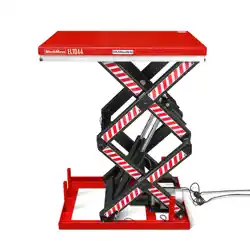
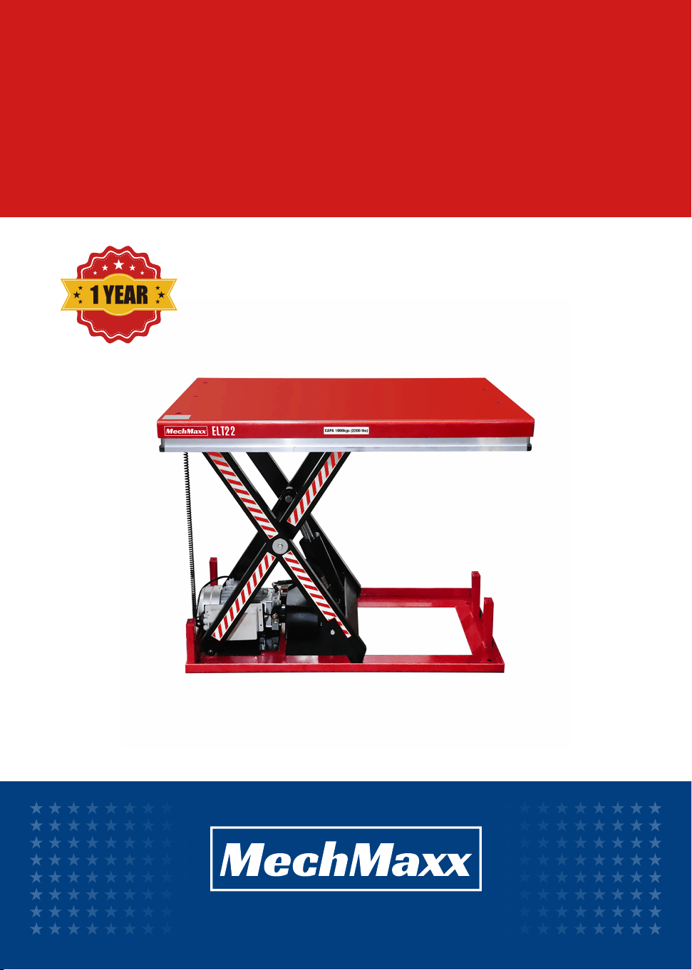
ELT22
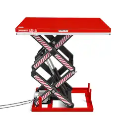
ELT44
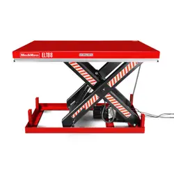
ELT88
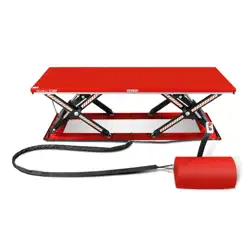
LOW PROFILE
LIFT TABLE

1
www. mechmaxx.com
TABLE OF CONTENTS
TABLE OF CONTENTS
6GREASING POINTS
6SERVICE INSTRUCTIONS
7TROUBLE SHOOTING
8LOW PROFILE LIFT TABLE ASSEMBLY
HYDRAULIC CRCUIT & ELECTRIC PRINCIPE DIAGRAM
5
OPERATING THE LIFT TABLE
4
DAILY INSPECTION 4
INSTALLATION 4
SAFETY 3
SAFETY PRECAUTIONS 3
BASIC DATA 2
LOW PROFILE
LIFT TABLE
2
www. mechmaxx.com
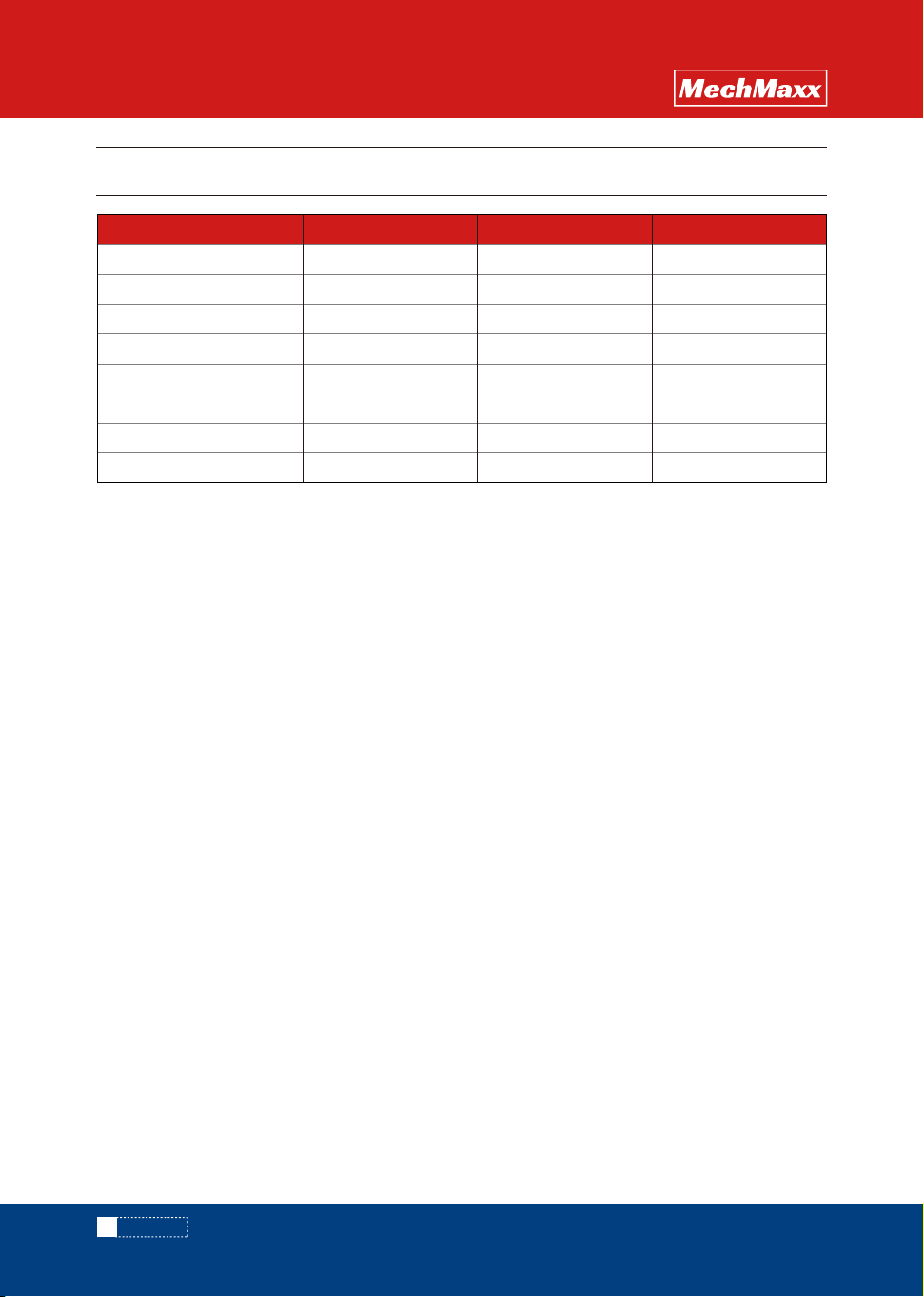
BASIC DATA
BASIC DATA
Capacity(lbs)
Model
2200 4400 8800
ELT22 ELT44 ELT88
Lowest Height (insh) 8 9 9.4
Max. Lift Height (insh)
39.4 41.3 43.3
Table Dimensions (insh)
32.3×51.2 33.5×51.2 47.2×66.9
Net Weight (lbs)
Approx. Lifting Time while
Loaded Rate Capacity(sec)
352.7 518.1 826.7
20~25 16~22 30~40
Packing Dimensions (insh) 51.6×32.3×8.3 51.6×33.9×9.4 67.3×47.6×9.8
LOW PROFILE
LIFT TABLE
3
www. mechmaxx.com
SAFETY PRECAUTIONS
SAFETY PRECAUTIONS
LOW PROFILE
LIFT TABLE
SAFETY
Note: This manual has been prepared for skilled and
competent personal. It provises instructions for using
the product correctly and parts list. This Manual cannot
replace the professional skills and expertise ofthe user:
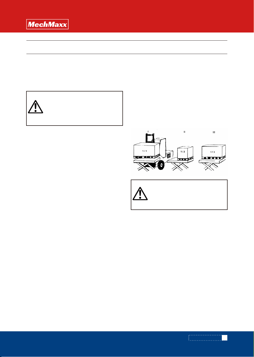
In accordance with EN1570, Safety Requirements for
Lifting Tables, the basic requirements are:
Ⅰ 100% of the rated load (maximu m load) uniformly
distributed over the entire
platform area.
Ⅱ or 50% of the rated load (maxi mum load) uniformly
distributed over half the length of the platform.
Ⅲ or 33% of the rated load (maxi mum load) uniformly
distributed over half the width of the platform.
▲ Read & thoroughly understand the instruction
manual completely before using. Follow all safety
instructions strictly.
▲ It is necessary to check all safety devices before
operation.
▲ Make sure that there are no obstacles in the working
area.
▲ Do not put foot or hand in scissors mechanism or
through frame.
▲ Screw the lifting eyes on the base frame before
working on the lift table.
▲ Do not overload the lif table. Load should be distributed
on the table according to relevant load distribution chart.
▲ Pay attention if local voltage and frequency is as
same as the input specification of the lift table.
▲ Use the lift table on flat and solid ground.
▲ All the electrical connection and disconnection
operations must be carried out by skilled and competent
personal.
▲ While operation, it is forbidden to contact the
moving parts of the lift table.
▲ While the lift table moving, it is forbidden to adjust
or to move the load.
▲ It is forbidden to lift the load, which perhaps does
harm to a person or other object.
▲ It is forbidden to operate the lift table while a person
is under the table.
▲ Do not adjust the safety valve of hydraulic power
pack.
▲ It is forbidden to operate the lift table even if there
is underf the table.
▲ Do not adjust the safety valve of hydraulic power
pack.
▲ It is forbidden to operate the lift table even if there
is small structure distortion.
▲ Do not use in an explosive or flammable place.
▲ The lift table is a moveable lifter designed to lift or
lower rated load. Do not use it for other purpose.
▲ Do not allow a person to operate the lift table, who
does not understand its operation.
▲ It is forbidden to change the lift table without manu-
facture's written admission.
▲ It is necessary to use the spare parts designated by
manufacturer.
▲ Make sure to keep a distance between the table and
ambient objects enough to operate the lift table safety.
▲ Keep the hydraulic system under clean and safe
condition.
▲ The hydraulic power pack features an electric lower-
ing control those coils. The coils must be fed with the
power supply voltage should not exceed + 10% of the
rated required votage.
▲ Always do maintenance and routine check while the
lift table is unloaded.
▲ The lift table is not waterproof and should be used in
a dry environment.
Note! Maximum load refers to the load being
uniformly distributed over the entire platform
area.
WARNING!
If operating the lift table improperly, a
person may be seriously! injured. Therefore,
operate properly according to the following
instruction.
CAUTION!
If operationg the lift table improperly. A
person may be iniured.Therefore,operate
properly according to the follwing instruction.
4
www. mechmaxx.com
SAFETY PRECAUTIONS
LOW PROFILE
LIFT TABLE
DAILYINSPECTION
OPERATING THE LIFT TABLE
1. The base frame of the lift table is not as standard
self-supporting. It is important that the flooring is flat
and stable and that the installation area or pit, when
necessary, is well drained.
2. Utilize a lifting sling through the scissor package. Tie
the base frame to the platform or the scissor mechanism.
Locate the table into the desire position. Turn the fixed
arm end to the side where the load will be moved on or off
at upper level.
See picture below.
3. Check the operation of the safety frame on all sides.
4. The control device should be positioned so that the
operator has a clear view over the lift table and the load
at all times when the lift is operated.
Daily inspection is effective to find the malfunction or
fault on the lift table.
Before operation, check the lift table according to the
following points.
▲ Check all the terms of WARNING and CAUTION.
▲ Check scratches, bending or crack on the lift table.
▲ Check smooth movement of the table.
▲ Check if there is any dydraulic oil leakage.
▲ Check the vertical creep of the table.
▲ Check if all the bolts and nuts are firmly tightened
The maximum capacity of the lift table is
2200lb/4400lb/8800lb. Load should be distributed on
the lift table equably.
▲ Screw and loose emergency stop switch.
▲ Push the UP button and power pack starts to work
to lift the load.
▲ Loose the UP button and power pack stops working,
▲ Push the DOWN button and the table will lower.
▲ Loose the DOWN button and the table will stop.
▲ The table is equipped with an aluminum guard to
avoid accidental danger.
▲ If aluminum guard strikes an object while the table
lowers, stop operation and check the lift table. After
making sure no any abnormality, strike the Up button
slightly and then the electric system will function as
before.
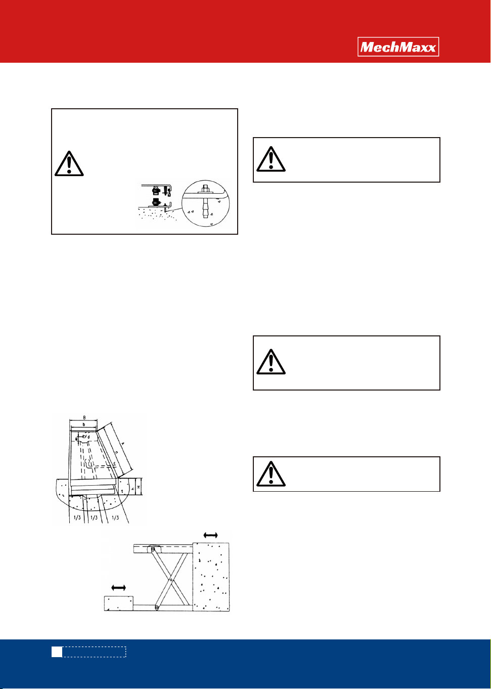
A. Pit length=a+30mm
B. Pit width=b+30mm
H. Pit depth=closed
height of table+5mm
a. Platform length
b. Platform width
c.Drainage hole (when
required)
d. Tube for external cables
and hoses Ф60mm
h. Lowest height
CAUTION!
Do not use the lift table if any malfunction or
fault is found.
WARNING!
Do not put foot or hand in scissors mechanism.
CAUTION!
Do not over load the lift table.Ensure the
banlance of loading. Do not load partially or
concentrically.
INSTALLATION OF LIFT TABLE ON THE
FLOOR/GROUND OR IN A PIT
Double or triple vertical scissors tables
must be fixed to the floor/ground.By means
of expander bolts or silimar, We also
remommend that all other lift table types,
with the exception of mobile units, are
securely affixed on the floor to Prevent
unintentional
movement
Mechanical/electrical installation
Loading
Lifting the Table
Lowering the table
Note
Pit drawing
Loading/unloading at
the fixed arm end
5
www. mechmaxx.com
SAFETY PRECAUTIONS
LOW PROFILE
LIFT TABLE
There are two methods of emergency stop as follows:
▲ Push down the emergency stop switch and the
movement of table stops.
▲ Strike aluminum guard upward and the movement of
table also stops.
Emergency stop
If necessary, the lift table can be transported with
attached righbolts.
▲ Pay attention to the maximum capacity of lifting
equipment to be used.
▲ Keep the righbolts with reasonableness.
Transportation
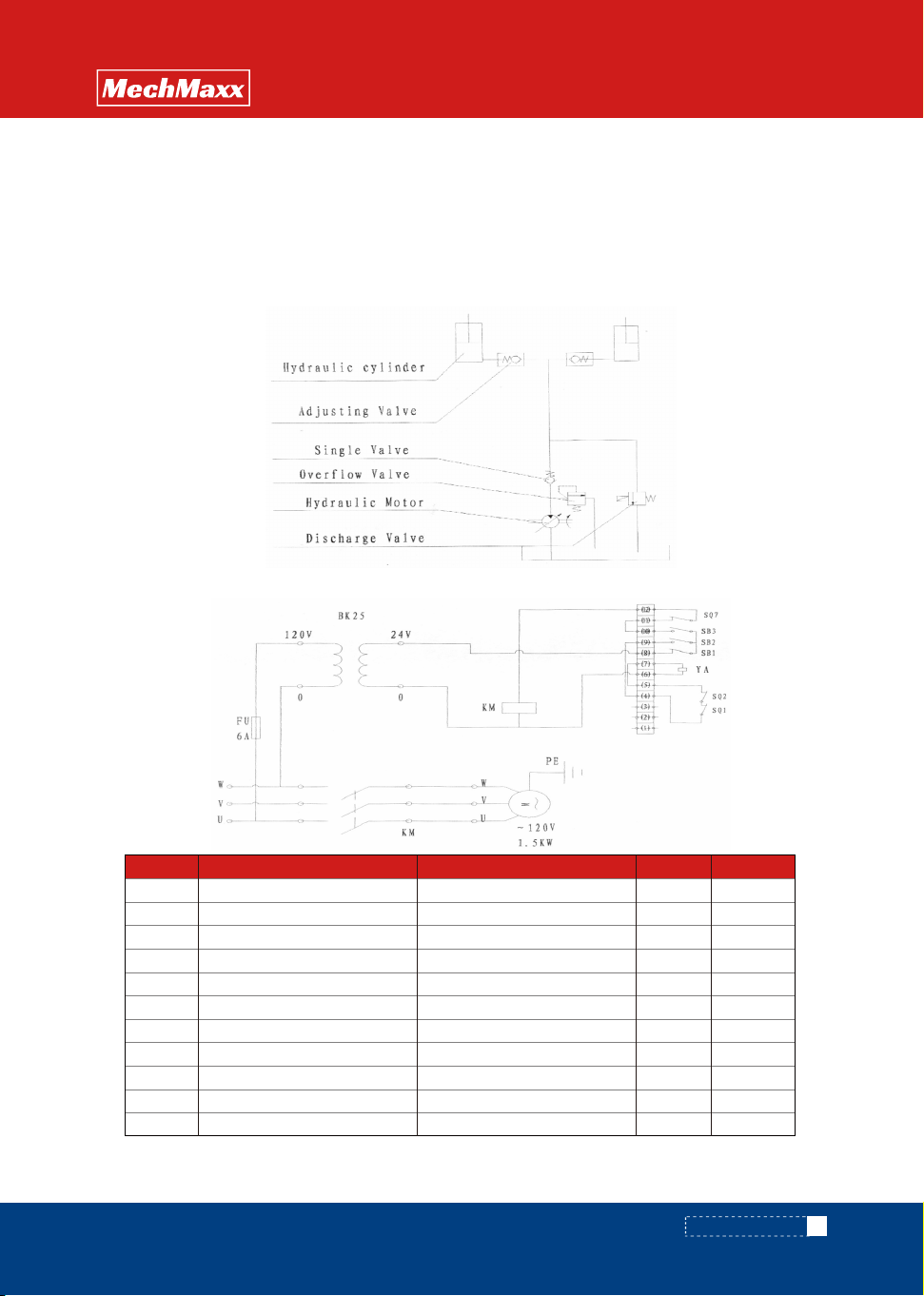
HYDRAULIC CIRCUIT & ELECTRIC PRINCIPLE DIAGRAM
See Figure 1 & Figure 2
Fig. 1 Hydraulic circuit
Fig. 2 ELECTRIC PRINCIPLE DIAGRAM
No.
BK
FU
KM
M
PE
SQ1-2
SQ7
YA
SB1
SB2
SB3
Description
Power Transformer 125W (120V-24V)
Fuse 1RT14-20 (6A)
Connect 1CJX2-1201/24V
Hydraulic Power Pack 1120V/1.5kw
Ground Wire 1
Control Switch-down 2TZ-8104
Control Switch-up 1
Fuse-down 1AC24V
Emergency Button 1
Button-up 1
Button-down 1
Specification Qty Marks
Content
After every 500 hours'
working or every
3 months later
After every 2000
hours' working or
every year
Check oil level of oil tank
Check the cleanliness of oil filter
Fasten all the connecting parts again
Check wear and tear of pressure oil pipes
Check hydraulic cylinder
Fix main parts tightly again
Check the function of micro-switches
Check whole working state of the lift table
Lubricate all the joints and privot points
Check wear and tear of all axial bushes
Replace hydraulic oil for the first time Accumulated working ten hours'
Replace hydraulic oil
Check oil leaking
Remark: ☆ stands for proceeding the item
☆
☆
☆
☆
☆
☆
☆
☆
☆
☆
☆
☆
▲ Do routine check of fasteners, packing and oil
leaking.
▲ Do routine check of the function of the lift table.
▲ Before service the lift table, make sure to turn off
the AC power supply.
▲ After service it is necessary to check the function of
the lift table again.
▲ ONLY a qualified personel can do service work.
▲ Do routine check of the micro-switches on the
safety guard.
▲ Do routine check of the hydraulic system by listening
its noise, touch motor's surface.
▲ Caution: It is necessary to turn off the AC power
supply before touch motor's surface
▲ Pay attention to clear or even replace the oil filter
after operating for a long time.
▲ Appropriate lubrication is necessary to make the lift
table work easily and have a prolonged service lift.
▲ Following table is recommended to service the lift
table periodically.
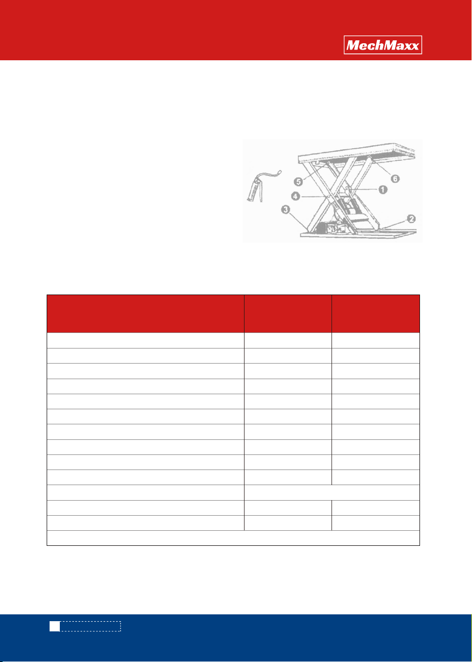
When greasing the bearing the lift table must not be loaded! When determining oil levels, bear in
mind that the tank contains the greatest amount when the lift table is in its lowest position,
Hydraulic oil must be treated as dangerous waste!
① Piston rod bearing
② Lower running wheel
③ Lower arm fixing
④ Arm center
⑤ Upper arm fixing
⑥ Upper running wheel
SERVICE INSTRUCTIONS GREASING POINTS
6
www. mechmaxx.com
SAFETY PRECAUTIONS
LOW PROFILE
LIFT TABLE
(23
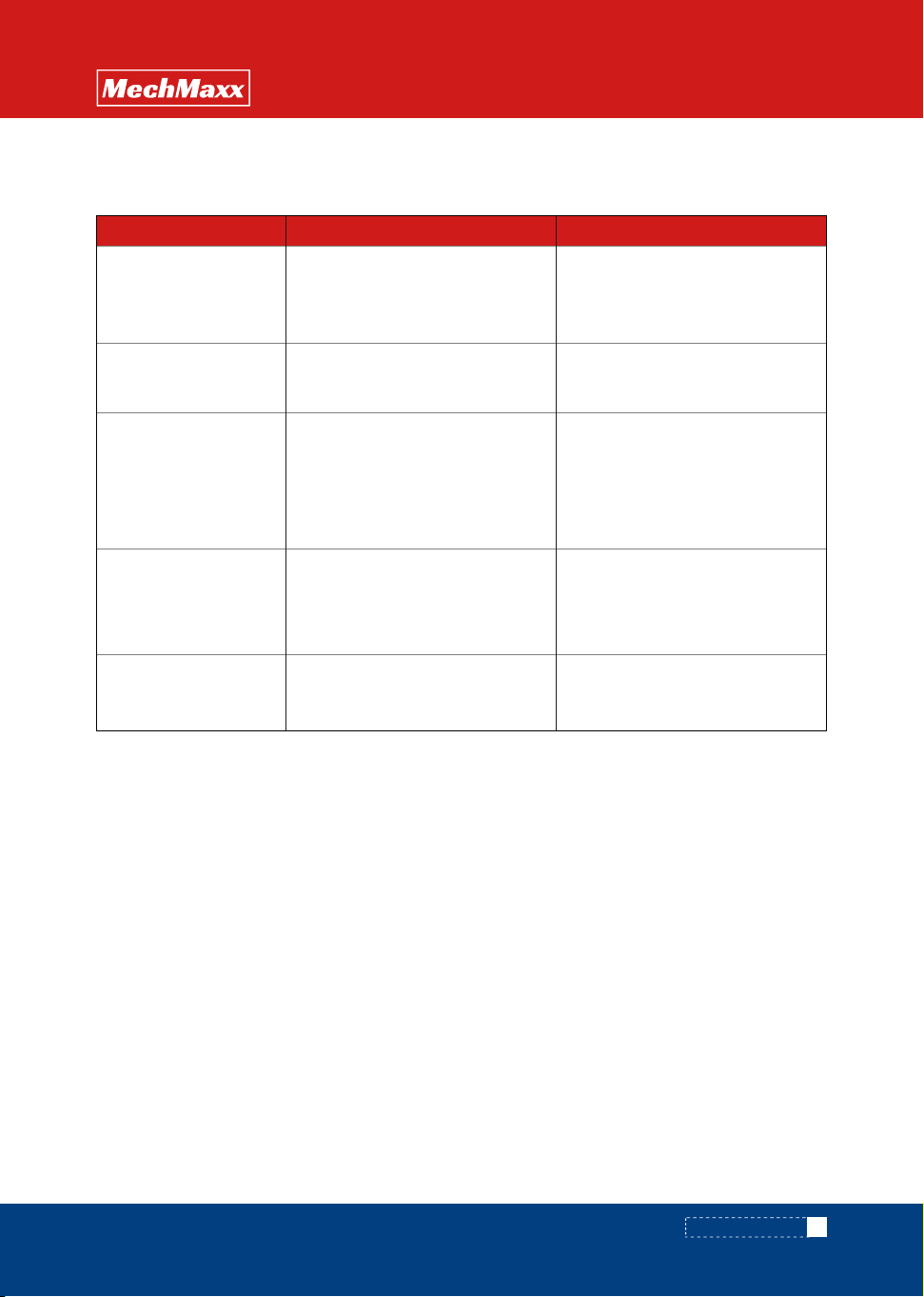
Remedy
1
CauseTrouble
Table cannot lift while
while motor works
mormally
▲
Eyebolt has not been removed
▲
AC Voltage phrases mistake
▲
Electromagnetic dysfunctions
▲
The table is overloaded
▲
Remove eyebolt
▲
Correct AC voltage phrase electro-
magnetic valve and repair it
▲
Remove excessive load
▲
Repair electromagnetic valve and if
necessary replace it
▲
Check and replace packing
▲
Replace lowering limit switch or
micro-switch.
▲
Check the function of electromagnetic
valve and repair it
▲
Strike the Up button slightly
▲
Replace electric circuit board
▲
Oil not enough
▲
Limit switch damaged
▲
Fill enough oil
▲
Check and repair limit switch. If
necessary, replace it
▲
Internal leaking in electromagnetic
valve
▲
Packing damaged in hydraulic
eylinder
▲
Lowering limit switch or micro-switch
on safety guard damaged
▲
Electromagnetic valve dysfunctions
▲
Safety guard works
▲
Something wrong with electric
circuit board
▲
Lowering limit switch (if switched)
damaged
▲
Replace limit switch
Table cannot lift and
motor does not work
Table cannot reach the
hightest position
Table cannot lower
Table's legs go over limit
position (if existed) while
table lowers
Cylinder
Note: Before service it is necessary to screw two eyebolts into relevant screw-holes on the basis lest the table
lowers accidentally.
7
www. mechmaxx.com
SAFETY PRECAUTIONS
LOW PROFILE
LIFT TABLE
TROUBLE SHOOTING
ELT22
8
www. mechmaxx.com
ASSEMBLY
LOW PROFILE
LIFT TABLE
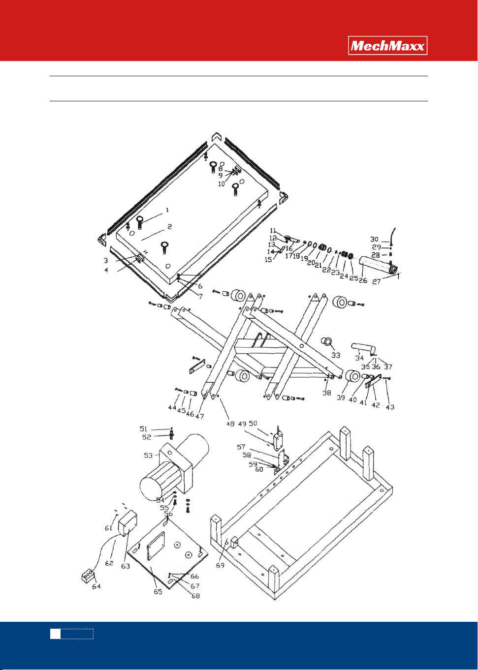
LOW PROFILE LIFT TABLE ASSEMBLY

9
www. mechmaxx.com
ASSEMBLY
QTYQTY
1
2
3
4
5
6
7
8
9
10
11
12
13
14
15
16
17
18
19
20
21
22
23
24
25
26
27
28
29
1
4
4
2
2
2
6
4
4
1
8
4
1
1
1
1
2
2
2
1
2
2
2
4
1
1
1
1
4
Lifting Bolt
Table
Switch
Fixed Board
Taper Spring
Aluminum Alloy Angle lron
Set Nut M8
Flat Washer Ф4
Spring Washer Ф4
Semicicle Screw M4×30
Oil Mouth
Bearing
Cylinder Pin
Spring Washer Ф8
Hex Cap Bolt M8×20
Lift Piston
Oil Seal TC50×62×7
C-ring Ф95
Steel C-ring
Top Nut
O-ring Ф80×3.1
O-ring Ф80×3.1
Steel C-ring Ф40×3.2
Piston
Oil Seal DAS80-62
Cylinder
Lock Pin Ф3.5×30
Safe Valve Assembly
O-ring Ф 10×1.9
30
4
High Pressure Oil Pipe
33
34
35
36
37
4
1
4
1
2
2
4
4
4
2
2
2
1
1
1
1
1
1
1
1
1
1
1
1
1
1
1
1
1
1
1
1
2
2
2
2
2
No Oil Bearing
Upper Scissor Pin
Flat Washer Ф8
Spring Washer Ф8
Hex Cap Bolt M8×20
PART DESCRIPTION PART DESCRIPTIONPART NO. PART NO.
Outer Scissor
Roller Guide
Roller Bushing
Separate Cover
Set Position Rod
Hex Cap Bolt
Hex Cap Bolt
No Oil Bearing
Scissor Cover
Inner Scissors
Set Nut M16
Semicircle Screw M4×25
Switch
O-ring Ф10x1.9
Oil Pipe Joint
Power Pack
Flat Washer Ф10
Spring Washer Ф10
Hex Cap Bolt M10x45
Fixed Board
Hex Cap Screw M6x12
Flat Washer Ф6
Spring Washer Ф6
Semicircle Screw M4x12
Wire
Batter Switch Cover
Button Switch
Install Board
Hex Cap Screw M8x20
Spring Washer
69
38
39
40
41
42
43
44
45
46
47
48
49
50
51
52
53
54
55
56
57
58
59
60
61
62
63
64
65
66
67
68 Flat Washer
Frame Seat
LOW PROFILE
LIFT TABLE
10
www. mechmaxx.com
ASSEMBLY
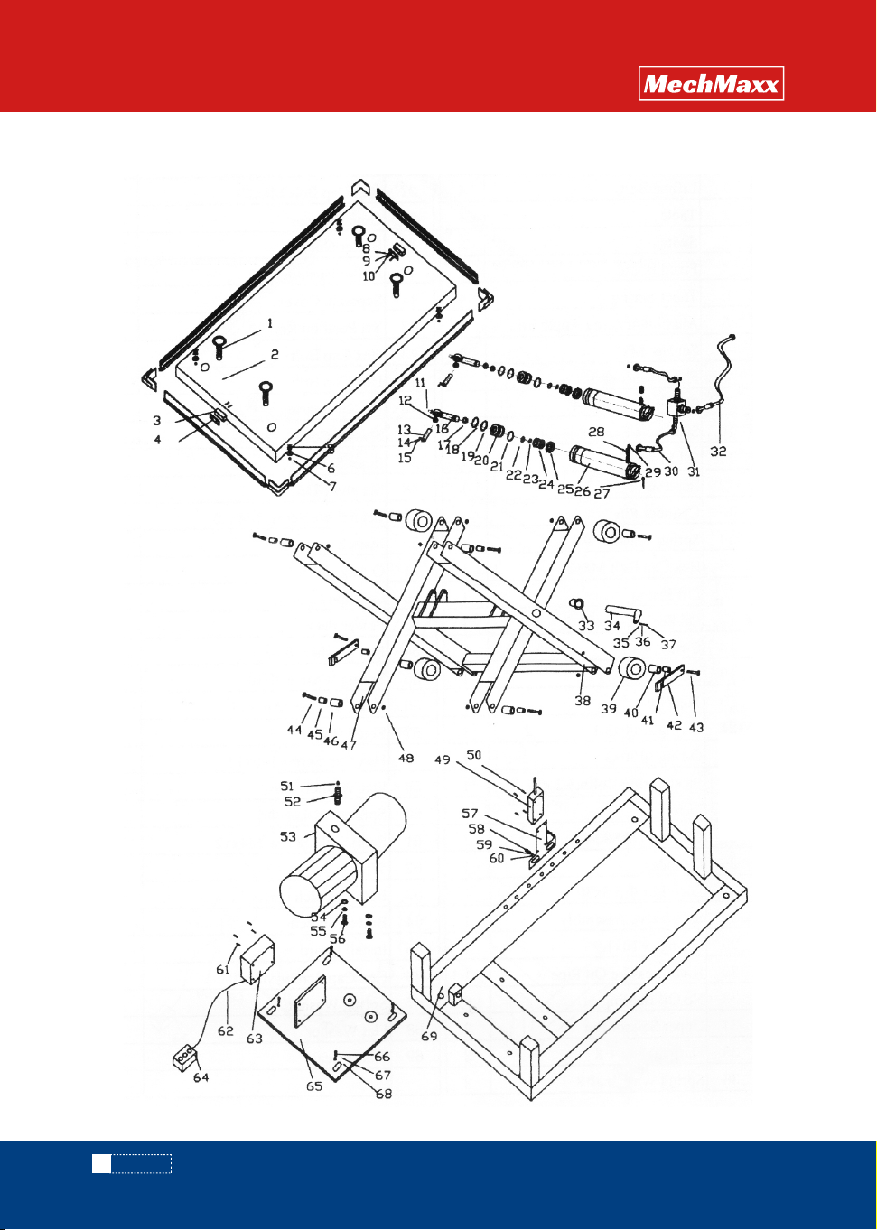
ELT44/ELT88
LOW PROFILE
LIFT TABLE
11
www. mechmaxx.com
ASSEMBLY
QTYQTY
1
2
3
4
5
6
7
8
9
10
11
12
13
14
15
16
17
18
19
20
21
22
23
24
25
26
27
28
29
1
4
4
2
2
2
6
4
4
1
8
4
1
1
1
1
2
2
2
1
2
2
2
4
1
1
1
1
4
Lifting Bolt
Table
Switch
Fixed Board
Taper Spring
Aluminum Alloy Angle lron
Set Nut M8
Flat Washer Ф4
Spring Washer Ф4
Semicicle Screw M4×30
Oil Mouth
Bearing
Cylinder Pin
Spring Washer Ф8
Hex Cap Bolt M8×20
Lift Piston
Oil Seal TC50×62×7
C-ring Ф95
Steel C-ring
Top Nut
O-ring Ф80×3.1
O-ring Ф80×3.1
Steel C-ring Ф40×3.2
Piston
Oil Seal DAS80-62
Cylinder
Lock Pin Ф3.5×30
Safe Valve Assembly
O-ring Ф 10×1.9
30
4
High Pressure Oil Pipe
T-joint
Long Hight Pressure Oil Pipe
31
32
33
34
35
4
1
4
1
2
2
4
4
4
2
2
2
1
1
1
1
1
1
1
1
1
1
1
1
1
1
1
1
1
1
1
1
2
2
2
2
2
No Oil Bearing
Upper Scissor Pin
Flat Washer Ф8
Spring Washer Ф8
Hex Cap Bolt M8×20
PART DESCRIPTION PART DESCRIPTIONPART NO. PART NO.
Outer Scissor
Roller Guide
Roller Bushing
Separate Cover
Set Position Rod
Hex Cap Bolt
Hex Cap Bolt
No Oil Bearing
Scissor Cover
Inner Scissors
Set Nut M16
Semicircle Screw M4×25
Switch
O-ring Ф10x1.9
Oil Pipe Joint
Power Pack
Flat Washer Ф10
Spring Washer Ф10
Hex Cap Bolt M10x45
Fixed Board
Hex Cap Screw M6x12
Flat Washer Ф6
Spring Washer Ф6
Semicircle Screw M4x12
Wire
Batter Switch Cover
Button Switch
Install Board
Hex Cap Screw M8x20
Spring Washer67
36
37
38
39
40
41
42
43
44
45
46
47
48
49
50
51
52
53
54
55
56
57
58
59
60
61
62
63
64
65
66
Flat Washer
Frame Seat
1
68
1
69
LOW PROFILE
LIFT TABLE