INSTRUCTION AND
INSTALLATION MANUAL
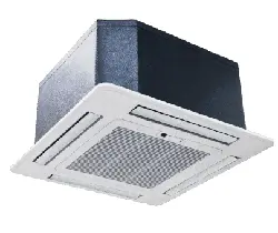
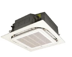
CEILING MOUNTED CASSETTE
AIR CONDITIONER
Compact Cassette
eiQ-CRFC18K
18,000 BTU
Round-Way Cassette
eiQ-SSRFC24K
24,000 BTU
eiQ-SSRFC36K
36,000 BTU
Round-Way Cassette
(3 Phase Outdoor)
eiQ-SSRFC48K
48,000 BTU
eiQ-SSRFC60K
55,000 BTU
Thank you for choosing an electriQ Air Conditioner
Please read this user manual before using this innovative
Air Conditioner and keep it safe for future reference.

2
CONTENTS
CONTENTS 2
SAFETY INSTRUCTIONS 3
HOW AIR CONDITIONERS WORK 5
OPERATION 6
PARTS 6
PANEL 7
OUTDOOR UNIT (DRAWINGS ARE FOR REFERENCE ONLY) 8
REMOTE CONTROL 9
MAINTENANCE 14
END OF SEASON 15
START OF SEASON 15
REPLACING THE BATTERIES 15
INSTALLATION GUIDE 16
TOOLS RECOMMENDED FOR INSTALLATION 18
INSTALLATION OF THE INDOOR CASSETTE UNIT 19
DRAINAGE PIPE INSTALLATION 24
PANEL INSTALLATION 26
INSTALLATION OF THE OUTDOOR UNIT 27
CONDENSATE DRAINAGE OF THE OUTDOOR UNIT 29
REFRIGERANT PIPE INSTALLATION 30
ELECTRICAL CONNECTION OF THE AIR CONDITIONER 36
TEST RUN 39
TROUBLESHOOTING AND SELF DIAGNOSIS 40
TECHNICAL SPECIFICATION 43
APPENDIX 46

3
SAFETY INSTRUCTIONS
IMPORTANT!
Carefully read the instructions before operating the unit
This appliance comprises of a cassette unit, a panel and an outdoor unit. The cassette is
designed exclusively for indoor installations while the external condenser can be installed
outside while still away from flood water or snow line.
Always place the unit on a dry and stable surface. Install the outdoor unit on a wall with wall-
mounting brackets or fix to a floor slab with special floor mounting slab bolts or brackets
away from flood or snow lines.
This appliance is intended for permanent installation into a fixed structure, and should not
be installed on vehicles.
The outdoor part of the air conditioner unit must always be stored and transported upright,
otherwise irreparable damage may be caused to the compressor; if in doubt we suggest
waiting at least 24 hours before starting the unit.
European Union regulations requires for an F-Gas trained engineer to handle any operation
where non-qualified intervention could cause fluorinated gas to escape. A commissioning
certificate must be issued with any installation.
This air conditioner contains R32 with a GWP of 675.
This air conditioner has been tested and is safe to use. However, as with any electrical
appliance - use it with care.
Disconnect the power before dismantling, assembling or cleaning.
Never connect the unit to an electrical outlet using an extension cord. Both the indoor and
outdoor units must be hardwired by a qualified electrician.
Never operate this appliance if the cord is damaged. Ensure the power cord is not stretched
or exposed to sharp objects or edges.
A damaged supply cord should be replaced by the manufacturer or a qualified electrician in
order to avoid a hazard.
Avoid touching any moving parts within the appliance.
Never insert fingers, pencils or any other objects through the guard
This appliance is not intended for use by persons (including children) with reduced physical,
sensory or mental capabilities. It is also not intended for use by those with a lack of
experience and knowledge, unless they have been given supervision or instruction
concerning the use of the appliance by a person responsible for their safety. Do not leave
children unsupervised with this appliance.
Do not clean the unit by spraying it or immersing it in water.
Any service other than regular cleaning or filter replacement should be performed by an
authorized service representative or a qualified air conditioning engineer. Failure to comply
could result in a voided warranty.
This air conditioner is intended for cooling / heating a room to a suitable level for human
comfort, and should not be used for any other purpose such as cooling food.
Avoid restarting the air conditioning unit unless 3 minutes have passed since being turned
off. This prevents damage to the compressor.
Never use the mains as a switch to start and turn off the air conditioning unit. Use the
provided ON/OFF button located on the remote control.
The indoor unit should not be installed in laundry or wet rooms.
After cleaning the mesh filter, reinstall it as soon as possible; do not operate the unit without
the mesh filter; otherwise it may affect the operation of the unit.
Lightning and other electromagnetic radiation sources may affect the operation of the unit.
During these conditions, disconnect the power supply and then power on after the
4
influence has been eliminated.
The operation parameters and protection device settings have been set during production;
these settings must only be changed by a qualified engineer with understanding of their
usage as incorrect settings could disable the unit’s protection features leading to damage of
the unit.
The unit must be sited far from any fire hazard. In case of fire due to short circuit, immediately
disconnect the power and extinguish the fire with a dry powder fire extinguisher. The unit
must only be installed by a qualified F-gas registered engineer.
Decommissioning or moving of the unit must only be carried out by a qualified F-gas
registered engineer.
Do not operate or store inflammable or explosive articles around or below the unit; otherwise
it may lead to a fire hazard.
If the unit is not to be used for a while, turn off the mains supply so as to avoid accident.
Avoid moisture ingress to the electric control system; otherwise it may lead to short circuit
or damage to the machine.
Please ensure the desired temperature is set correctly, especially when elderly, children or
people with limited mobility or mental capability are within the room.
In case of breakdown, the user should report the fault to the retailer or manufacturer for
consultation and repair rather than attempting diagnosis or repair; attempted repairs of the
unit by non-professional staff may lead to personal injury or damage to the unit, and may
invalidate the warranty.
In case of refrigerant leak, the stress meter will stop the operation of unit, a qualified F-gas
engineer should be contacted to arrange service;
The refrigerant may discompose into a harmful gas if allowed into contact with an open fire.
Do not touch the exhaust side pipe fittings to avoid scalding since the temperature may be
in excess of 100°C.
Sharp edges and the fin surfaces must not be touched to prevent the risk of cuts or injury.
WARNING
Do not use means to accelerate the defrosting process or to clean,
other than those recommended by the manufacturer.
The appliance shall be stored in a room without continuously
operating ignition sources (For example: open flames, an operating
gas appliance or an operating electric heater)
Do not pierce or burn.
Be aware that refrigerants may not contain an odour.
ENERGY SAVING AND UNIT SAFETY PROTECTION TIPS
Do not cover or restrict the airflow from the outlet or inlet grills.
For maximum performance the minimum distance from a wall or objects should be 50cm.
Keep the filters clean. Under normal conditions, filters should only need cleaning once every four
weeks (approximately). Since the filters remove airborne particles, more frequent cleaning maybe
necessary, depending on the air quality.
For the initial startup set the fan speed to maximum and the thermostat to 4-5 degrees lower than
the current temperature. After, set the fan switch to low and set the thermostat to your desired
setting.
To protect the unit we recommend not using the cooling mode when the ambient indoor
temperature is higher than 35℃.
To protect the unit we recommend not using the heating mode when the indoor ambient
temperature is lower than 7℃. Performance will be reduced at lower temperatures.
Note the manufacturer operating temperature ranges at the end of this user manual.
5
HOW AIR CONDITIONERS WORK
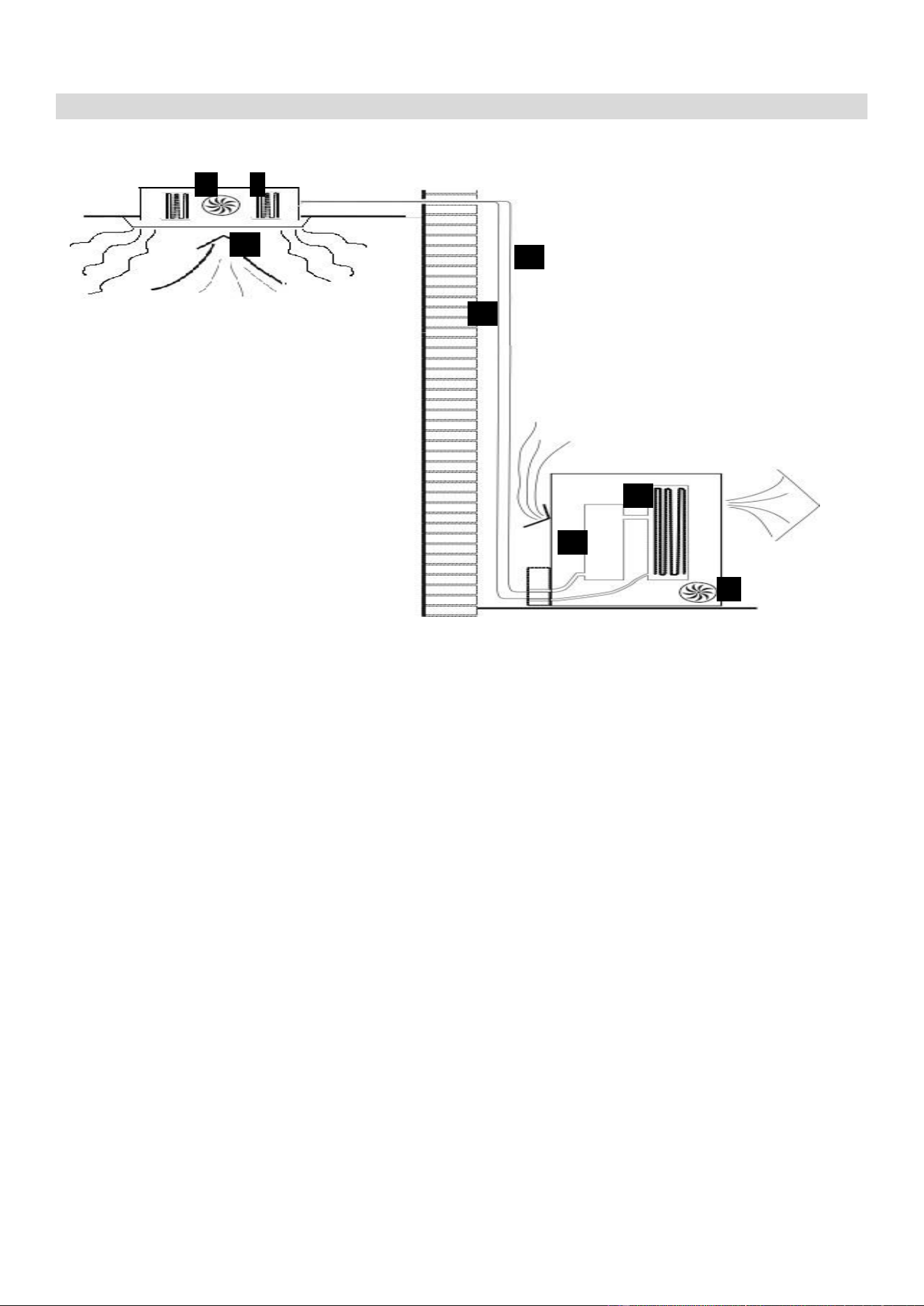
COOLING MODE
The compressor (6) in the external unit compresses the refrigerant into a high-temperature, high-
pressure gas. When this gas flows along the cooling fins of the condenser (7), heat is exuded and
the gas condenses into a liquid, which is then led to the evaporator (1) in the indoor unit. The liquid
expands into a gas at a low temperature and low pressure. This gas absorbs the warmth of the air
in the room, and a fan (3) draws the air through the filter and over the evaporator (1), blowing the
cooled air back into the room. The heat is moved to the compressor along with the gas. A fan (8)
draws air over the condenser and blows the warm air away.
1. Evaporator
2. Filter
3. Evaporator Fan
4. Gas Line
5. Liquid line
6. Compressor
7. Condenser
8. Condenser Fan
HEAT PUMP MODE
The system operates in reverse: the condenser works as an evaporator, the evaporator as
a condenser: warm air is blown into the room. It is ideal as a maintenance heating when
outside temperature is not too low and when the indoor temperature is more than 7°C.
DEHUMIDIFYING
As with cooling, the moisture in the air condenses on the cold evaporator at room temperature
acting as a powerful dehumidifier.
3 1
2
4
5
7
6
8
6
OPERATION
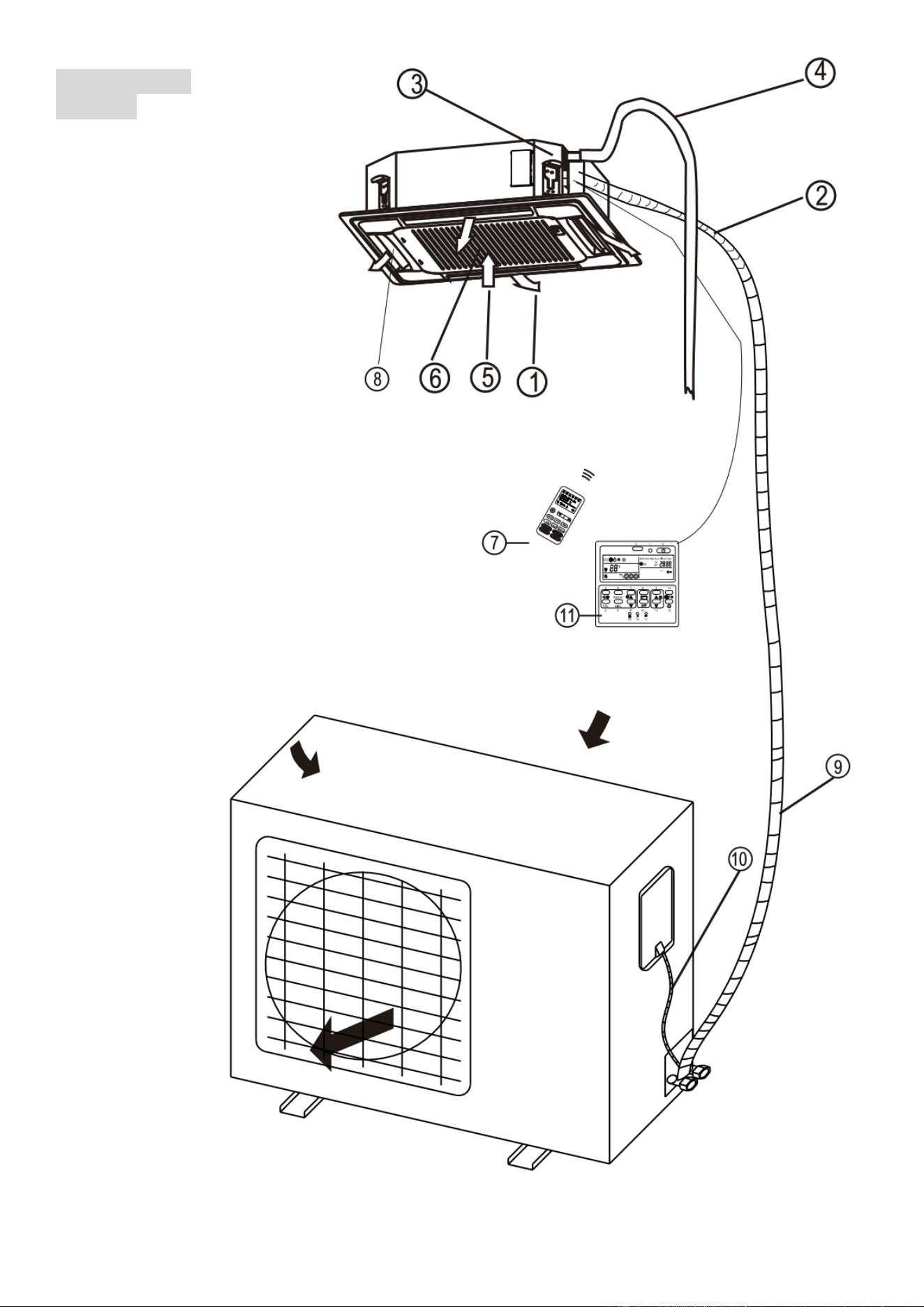
PARTS
INDOOR UNIT
1
Air Outlet
2
Refrigerant pipe junction
3
Uplift Pump
4
Drainage Pipe
5
Air Return
6
Filter
7
Remote Control
8
Louvre for airflow
9
Refrigerant pipes
10
Interconnecting Cable
11
Optional Wall Controller
OUTDOOR UNIT
7
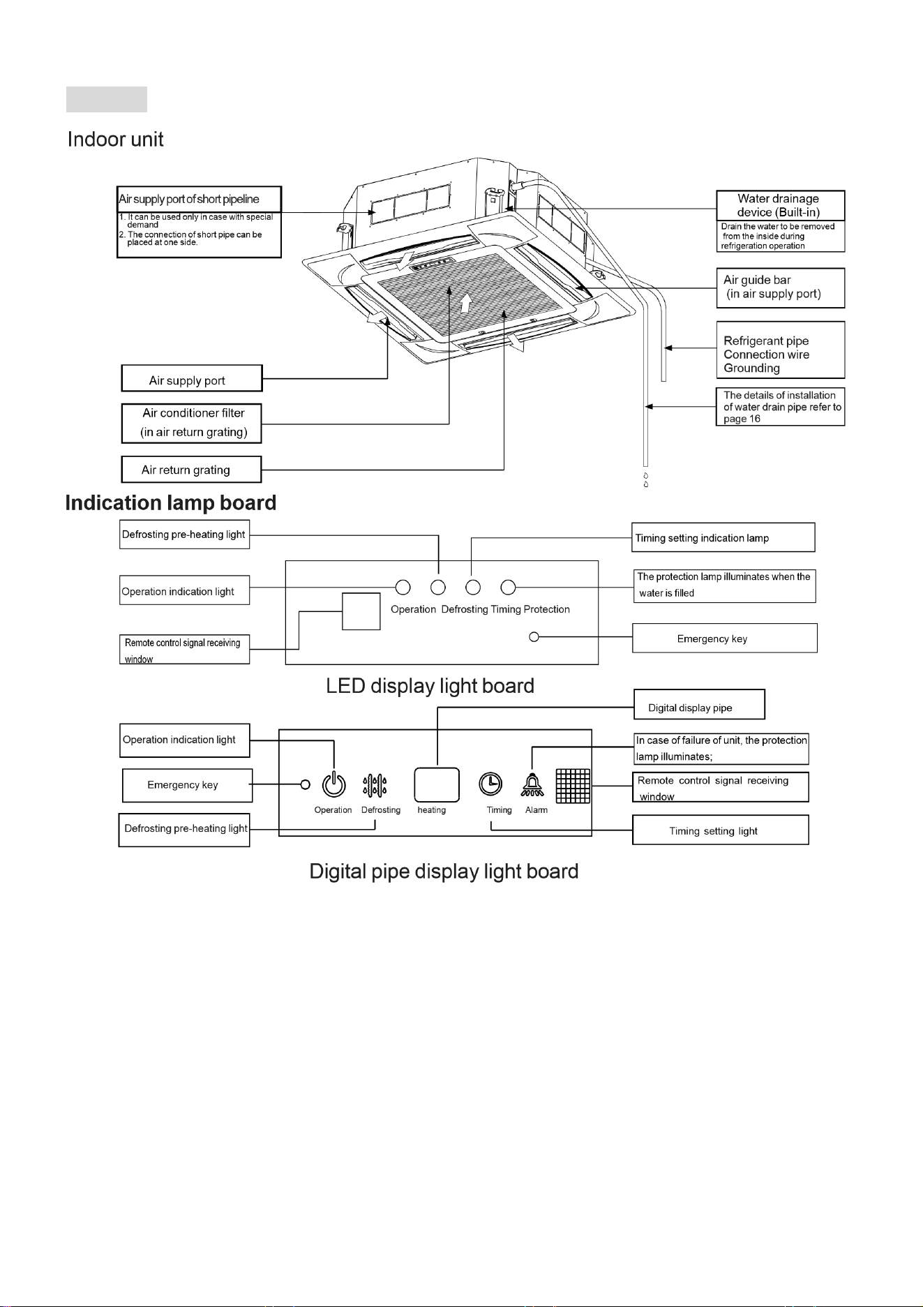
PANEL
8
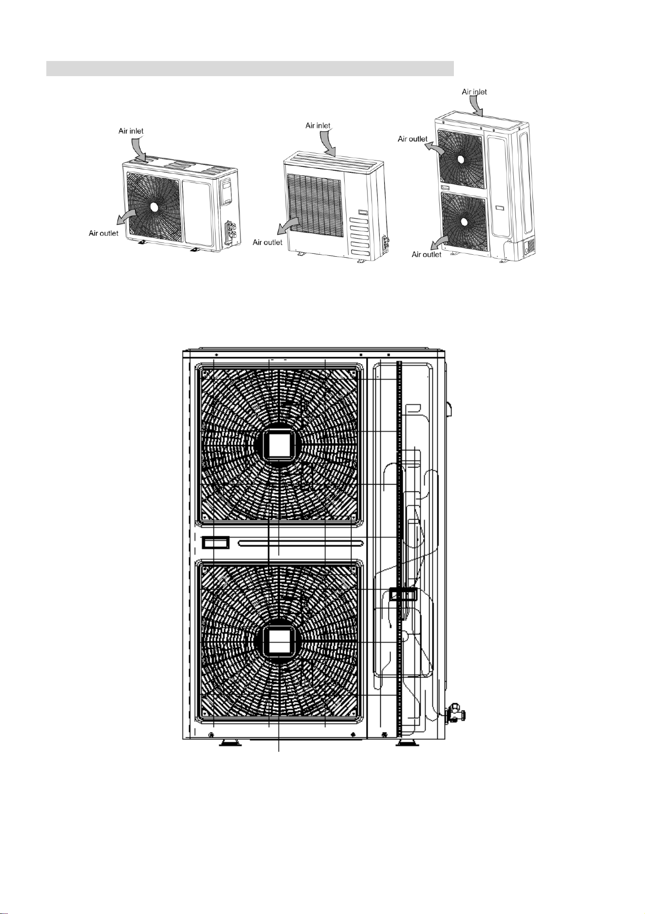
OUTDOOR UNIT (DRAWINGS ARE FOR REFERENCE ONLY)
9
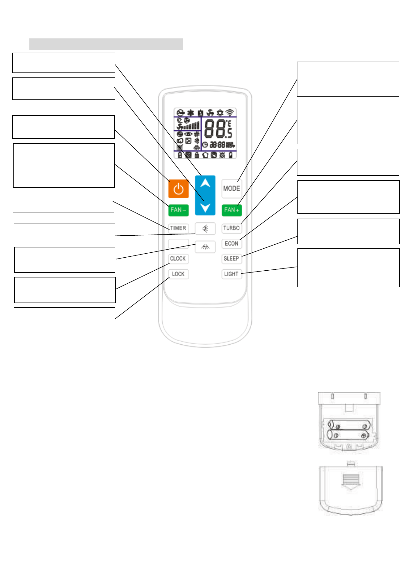
REMOTE CONTROL DIAGRAM
NOTICES FOR REMOTE CONTROL:
1.
Do not place the remote control near high temperature heat sources.
2.
Do not leave the remote control exposed to the direct sunshine.
3.
Be careful not to drop the remote as this may lead to damage.
4.
There must be no barrier between the signal receiver and remote control
as this may affect communication between them.
5.
Do not allow the remote control to be splashed or immersed in water.
6.
Do not place heavy items on top of the remote control.
Note: In case of failure of the remote control, please remove the back cover
and replace the batteries, before repeating the operation; if the failure still
exists, please run the air conditioner using the emergency operation method,
and contact the manufacturer or retailer.
POWER
Turn the appliance On / Off.
REDUCE FAN SPEED
Reduce the fan speed by one level.
Please note: When on the lowest fan
speed it will change to auto.
Pressing again will change the unit
to high
TIMER
Turn the timer ON/OFF.
CLOCK
Press to adjust the current time.
LOCK
Press to lock the buttons on the
remote.
INCREASE TEMPERATURE
Increase the desired temperature.
INCREASE FAN SPEED
Increase the fan speed by one level.
Please note: When on the highest
fan speed it will change to auto.
Pressing again will change the unit to
low.
TURBO (dependant on model)
Enter the turbo function for enhanced
short term performance.
ECON
Automatically sets the desired
temperature to 26 ℃ in cooling or
heating mode.
SLEEP (dependant on model)
The air conditioner will enter sleep
mode.
LIGHT (Dependant on model)
Forced closing or lighting of display
panel. Decide whether to have this
function according to the actual
model.
VERTICAL SWING
Press to activate the vertical swing.
HORIZONTAL SWING
(Dependant on model)
Press to activate the horizontal
swing.
MODE
Select between automatic, cooling,
dehumidification, fan and heating
modes.
REDUCE TEMPERATURE
Decrease the desired temperature.
10
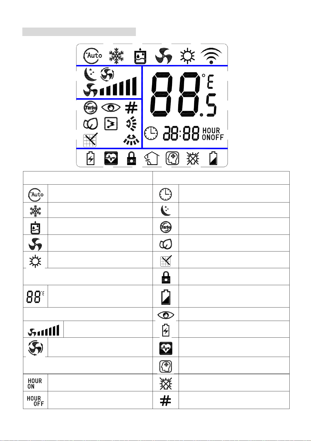
REMOTE CONTROL DISPLAY
MODES
OTHER ICONS
AUTO MODE
CLOCK
COOLING MODE
SLEEP FUNCTION
DEHUMIDIFIER MODE
TURBO FUNCTION
FAN MODE
ECON FUNCTION
HEATING MODE
CLEANING FUNCTION
TEMPERATURE DISPLAY
REMOTE LOCKED
CURRENT TEMPERATURE
Ranges between 16 - 32C
BATTERY LOW
FAN SPEED
AUTO CONFIG
LENGTH OF BAR
INDICATES FAN SPEED
POWER SAVING MODE
AUTOMATIC FAN SPEED
HEALTH MODE
TIMER
INTELLEGENT MODE
ON TIMER
BACKLIGHT OFF
OFF TIMER
ADDRESS

11
REMOTE CONTROL FUNCTIONS
POWER
This button will turn the air conditioner On and Off.
1. When first powered on, air conditioner will start with the default settings:
Desired temperature 25°C
Automatic mode and Automatic fan speed.
Vertical and Horizontal Swing.
TURBO, Sleep, Timer and lock off.
2. When powered on subsequently the unit will continue with the previously used settings but
sleep, TURBO, ECON and timer functions will be cancelled if previously activated.
MODE
1. Press this button to change between Automatic, cooling, dehumidify, fan and heating modes.
2. The dehumidification mode is set with a desired temperature of 25℃ and the temperature
cannot be adjusted.
REDUCE TEMPERATURE ▼
1. When pressing this button, the desired temperature will be reduced by 1°C. When pressing
this button in dehumidification and fan modes, the desired temperature will not be adjusted.
2. After the clock button has been pressed (The clock icon will flash), this button is used to set
the time.
INCREASE TEMPERATURE ▲
1. When pressing this button, the desired temperature will be increased by 1°C. When pressing
this button in dehumidification and fan modes, the desired temperature will not be adjusted.
2. After the clock button has been pressed (The clock icon will flash), this button is used to set
the time.
VERTICAL SWING - EXTERNAL FLAPS (Dependant on Model)
1. Press this button to change the vertical swing between fixed position and swing operation.
2. Press this button in dehumidify mode to close the external flaps.
HORIZONTAL SWING - INTERNAL FLAPS (Dependant on Model)
1. Press this button to change the horizontal swing between fixed position and swing operation.
2. Press this button in dehumidify mode to close the internal flaps.
REDUCE FAN SPEED
1. Press this button to reduce the fan speed. When going below low, the unit will enter Automatic
mode. When pressed again the fan speed will be set to high.
2. In dehumidify mode, the fan speed is fixed to low and is not adjustable.
INCREASE FAN SPEED
1. Press this button to increase the fan speed. When going above high, the unit will enter
Automatic mode. When pressed again the fan speed will be set to low.
2. In dehumidify mode, the fan speed is fixed to low and is not adjustable.

12
TIMER
The timer can be used as a start timer or a shutdown timer and can be set between 1 hour and
24 hours in 1 hour increments. This is a one use timer, and multiple timers cannot be combined.
START TIMER
1. With the air conditioner turned off, press the timer button, before using the ▲and ▼buttons
to set in how many hours you would like the unit to start.
2. The unit will operate with the settings used before the appliance was turned off.
SHUTDOWN TIMER
1. With the air conditioner running with the desired setting, press the timer button, before
using the ▲and ▼buttons to set in how many hours you would like the unit to turn off.
TURBO (Dependant on model)
1. The TURBO button will not work in Automatic, Dehumidify or fan modes.
2. Press this button in cooling or heating modes to turn the TURBO function on or off.
3. When in the TURBO mode the fan speed will not be displayed.
4. Switching modes or pressing the sleep button will turn off TURBO mode.
ECON
1. The ECON button will not work in automatic, dehumidify or fan modes.
2. Press this button in cooling or heating modes to turn on ECON mode.
3. When in ECON mode, the desired temperature is set to 26℃.
4. When ECON mode is turned off the desired temperature will return to the value before the
button was pressed.
5. Switching between modes will turn off ECON mode.
SLEEP
1. Sleep mode can be activated in all modes apart from Fan mode.
2. Switching mode will cancel the sleep function.
3. When sleep mode is activated the fan speed will automatically be set to low, but can still be
increased if necessary (except in dehumidification mode).
LIGHT (Dependant on Model)
1. Press to turn the backlight on and off.
CLOCK
1. This button is used to set the clock. Press to adjust the hour value, the hour figure on the LCD
will flash. Use the ▲and ▼ buttons to adjust.
2. When the hour is set, press the clock button again to adjust the minute value, the minute figure
on the LCD will flash. Use the ▲and ▼ buttons to adjust.
3. After adjusting, press the clock button again to confirm the time set. If no buttons are pressed
for 3 seconds, the changes will be cancelled and the remote will return to normal operation.
LOCK
1. Press the Lock button to lock the buttons on the remote control.
2. When the remote is locked, the only button still active is the lock button
BUTTON COMBINATION: FAN - + FAN +
Will change the remote from showing 3 fan speeds to 6 fan speeds. As the air conditioners only
supports 3 speeds, 1/2 is Low speed, 3/4 is Medium speed, and 5/6 is high speed.

13
IMPORTANT INFORMATION
AUTO RESTART
The air conditioner will automatically restart when electricity is restored after a power cut. If in
doubt, check the settings.
RANGE OF INTERNAL THERMOSTAT
The internal thermostat can be set at a desired temperature between 16 and 32°C. Note that
whether the desired value is achieved depends on the room size, temperature and insulation of
the room.
RANGE OF HEAT PUMP FUNCTION
The heat function can be used when the external ambient temperature is above -15°C. The
performance of the heat pump will degrade with lowering external temperatures. Please note the
performance will reduce when the outdoor temperature drops below 5°C.
CAPACITY
The required cooling or heating capacity depends greatly on the location and/or use of the room
where the air conditioner is installed. Strong sunlight and the presence of people, lights or
equipment creates an additional heat load. Normal living spaces require about 350 Btu per
square metre of floor surface. In strong sunlight or if other sources of heat are present, this may
be as much as 1200 Btu per sqm.
Tip: On warm days, let the air conditioner cool the room as much as possible during the night
and keep the temperature constant from night to daytime.
14
MAINTENANCE
FILTERS
Ensure the power is turned off to the unit before attempting to service the filters.
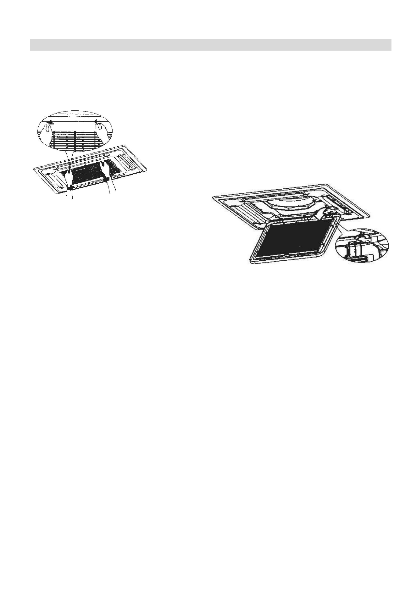
REMOVING THE GRILL
1.
Push the two grill switched towards the centre to
unhook the grill before pulling the centre of the panel
downwards.
2.
Care must be taken with the electrical
connectors (connecting the panel to the
main cassette) If necessary these
should be disconnected.
3.
Hold the grill at a 45 angle to the unit
and lift to unhook from the rear of the
panel.
4.
The filter can then be removed from the grill for cleaning.
CLEANING THE FILTERS
Clean the air filter with a vacuum cleaner or rinse with clean water.
If the filter is heavily soiled, a soft brush should be used with mild detergent.
Ensure the filter is fully dried before reinserting back into the grill and reattaching to the unit.
CLEANING THE OUTDOOR UNIT
While the unit is disconnected from power. Remove dirt and keep the air intake and exhaust
openings free of debris, etc. Cleaning with chemicals may cause damage.
15
END OF SEASON
If the air conditioner is not going to be used for an extended period:
•
Set in fan mode on a slightly warm day so that the inside of the appliance dries out.
•
Switch off the power at the fuse box and remove the batteries from the remote control.
•
Clean the filters.
•
Remove the batteries from the remote control.
•
Disconnect the power from the appliance
START OF SEASON
If the air conditioner is to be used again after an extended period:
•
Check that the air intake and exhaust openings of the interior and exterior units are not
blocked. Remove any dirt or debris that has accumulated.
•
Check that the filter is installed within the indoor unit and is clean.
•
Check that the condensation outlet drains properly and there is no dirt or organic blockage
(otherwise leakage may occur)
•
Install 2 AAA batteries in the remote control.
•
Check that the wiring between the cassette and the panel is connected, and there is no
damage to the interconnecting wires.
•
Turn the appliance on, set the time and desired setting.
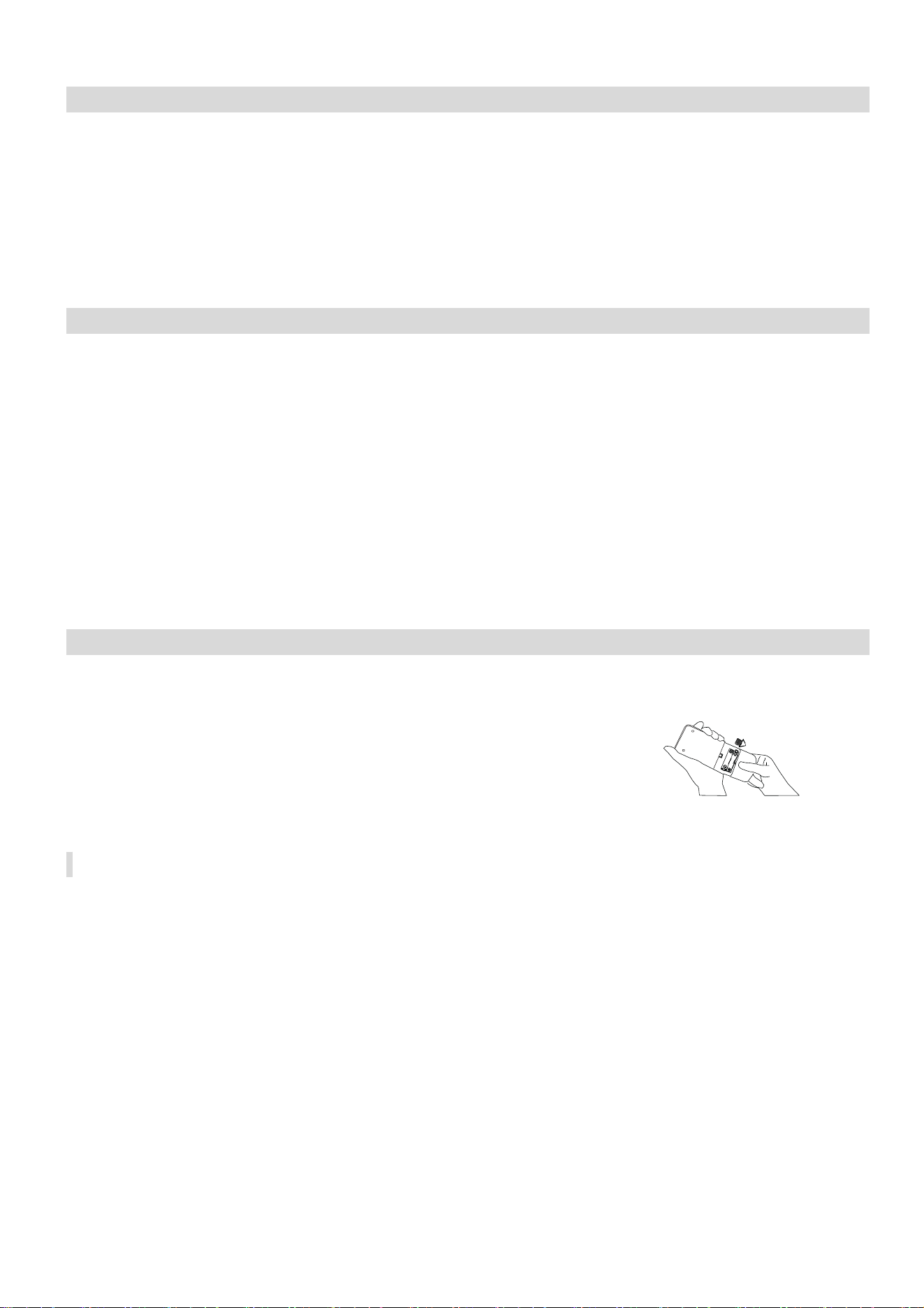
REPLACING THE BATTERIES
•
Remove the cover from the rear of the remote control.
•
Replace the AAA batteries, ensuring the correct polarity.
•
Reinstall the cover on the rear of the remote control.
•
If nothing is displayed on the remote, try pressing the power
button. If still no response, check the polarity of the batteries and
try replacing.

16
INSTALLATION GUIDE
SAFETY
Only qualified personnel should install this appliance. This installation manual is intended
for use by individuals possessing adequate backgrounds and qualifications in electrical,
electronic, refrigerant and mechanical fields. Any attempt to install or repair the appliance
may result in personal injury and property damage.
The manufacturer and retailer cannot be responsible for the interpretation of this
information, nor can it assume any liability in connection with its use.
The units are designed for permanent installation.
The equipment is designed for domestic or office use and we are not making any
endorsements for use in industrial or maritime environment.
Do not place near sources of heat, vapours, industrial machine oil or other
flammable gases.
High-frequency waves generated by radio equipment, welders and medical equipment
will interfere with the normal operation of the unit.
Install this device only when it complies with local/national legislation, ordinances and
standards.
Check the mains voltage and frequency. The information, specifications and parameter
are subject to change due to technical modifications or improvement without any prior
notice. The accurate specifications are presented on the nameplate label.
Please read this installation manual completely before installing the product.
When the power cord is damaged, replacement work shall be performed by authorized
personnel only.
Installation work must be performed in accordance with all European, national and / or
local directives and standards and must be done by authorized personnel only.
Always make sure to wear the correct personal safety protections such as protective
eyewear, gloves, ear protection etc.
This air conditioner contains a refrigerant and can be classified as pressurized
equipment. Therefore always contact an authorized air conditioning engineer for
installation and maintenance of the air conditioner.
The air conditioner must be inspected and serviced on an annual basis by an authorised
air conditioning engineer.
Each indoor unit has a separate refrigerant circuit, and as such each circuit must be
individually pressure tested and purged during installation.
Rating: This unit must be only connected to a suitable earthed power source.
The unit should use an independent power supply switch and a separate circuit to other
electric appliances; use a power supply cable with specified section area to supply the unit
and equip the circuit with the correct rating of circuit breaker (with electric leak protection
function).
Installation must be in accordance with the regulations of the country where the unit is
used.
Diagrams and pictures provided within the manual are for guidance only. Due to continual
product development, if there is any variance between the manual and the product
received, the information provided on the product should be followed.
The outdoor unit must be mounted in an area sheltered from excessive rain and direct
sunlight; we will not be liable for problems caused by installation in an unsuitable location.

17
The appliance must be installed 2 - 3m above floor level.
The unit must be mounted with an earth wire with the specified section area and securely
mounted; do not connect the earth wire with the earth wire of gas pipelines, water pipelines,
arrester conductor or phone systems so as not to cause an electric shock risk.
The main power supply switch of unit should be placed out of reach of children so as not to
cause a hazard.
INDOOR UNIT POSITION
The air inlet and outlet vent should be away from any obstruction, ensuring that there is a good
airflow through the whole air-conditioned space. Select a position where the condensing water can
be easily drained out, and the indoor unit can be easily connected to outdoor unit. The ceiling where
the unit is fixed should be strong enough to withstand the full weight and vibration of the unit. The
unit should be accessible for service and maintenance. The height of the installed unit should be
more than 200cm from the floor. The air conditioner must not be installed in a wet environment
such as a bathroom, shower or swimming pool etc.
OUTDOOR UNIT POSITION
A convenient position, dry and well ventilated, outside of direct sunlight or strong winds, which is
not on a flood line and where noise and airflow does not cause interference or inconvenience.
Select a location where there are no obstructions to the inlet and outlet vents. The location
should be able to withstand the full weight and vibration of the outdoor unit and permit safe
installation.
Make sure that the outdoor unit is installed in compliance with the installation dimension diagram
with easy maintenance access. Select a place where it is out of reach of children. Do not block
utilities access or fire escapes.
The external unit must be lifted and put in place by two people.
NOTES:
1. Only use a power supply with the correct ratings, making sure the correct sized power cables
are used
2. The appliance shall be installed in accordance with standard wiring regulations by qualified
personnel
3. Only replace fuses according to their printed rating or corresponding pcb boards.
18
TOOLS RECOMMENDED FOR INSTALLATION
Please note this is not an exhaustive list, and is provided as guidance for the most commonly
required tools.
Electric Drill
Hammer
Screwdrivers
Tape Measure
Core Hole Cutter
Spirit Level
Number 14 (7mm)
Masonry Drill
Pencil and Chalk
4 x M10 threaded
rods
Small Stepladder
7mm Wall Plugs
Protective Glasses
and Mask
Pipe and Cable
Detector
4 inch Plastic Ties
2 Inch Pipe Clips
Circuit Breaker
Garden Gloves
Dust Sheets
Foam Filler
Silicone Sealant
19
INSTALLATION OF THE INDOOR CASSETTE UNIT
Where possible the following areas should be avoided to avoid potential problems with the
appliance and/or safety risks:
1.
Where flammable gas is likely to be in the air.
2.
Where the air has a high salt content
3.
Where caustic gasses are likely to be in the air.
4.
Which is unable to safely bear the weight of the unit
5.
With high levels of electromagnetic interference.
6.
Where the unit may be subjected to acid or alkaline solutions.
7.
With high levels of humidity.
Select the installation location taking consideration of the following:
1.
Route of the pipework / wiring
2.
Access to the upper parts of the unit for connection of the pipework/wiring after hanging
the unit
3.
Ability of the area to support the weight of the unit.
Before hanging the unit the refrigerant pipes, drain pipe and connection wires should be led to
the location of the outdoor unit. Confirm the size of the indoor unit and ceiling opening using the
supplied installation template.
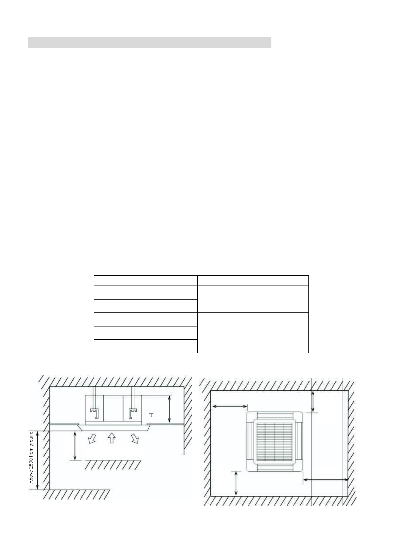
SPACE REQUIRED FOR INSTALLATION
Model
Machine body height (H) mm
eiQ-CRFC18K
267
eiQ-SSRFC24K
230
eiQ-SSRFC36K
285
eiQ-SSRFC48K
285
eiQ-SSRFC60K
285
Above1500
Above1500
Above1500
Above1500
Exhaust
Exhaust
Air inlet
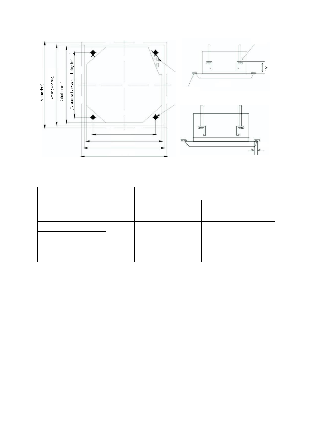
20
Hoisting
bolt x4
Above
Hanging
Bracket
Refrigerant
A
Ceiling
D(
Distance
between
hoisting
b
)
olts
C(indoor unit)
B(ceiling opening)
A(trim plate)
Unit: (mm)
Model
Size
A
B
C
D
E
eiQ-CRFC18K
650
610
565
528
528
eiQ-SSRFC24K
890
890
840
680
780
eiQ-SSRFC36K
eiQ-SSRFC48K
eiQ-SSRFC60K
21
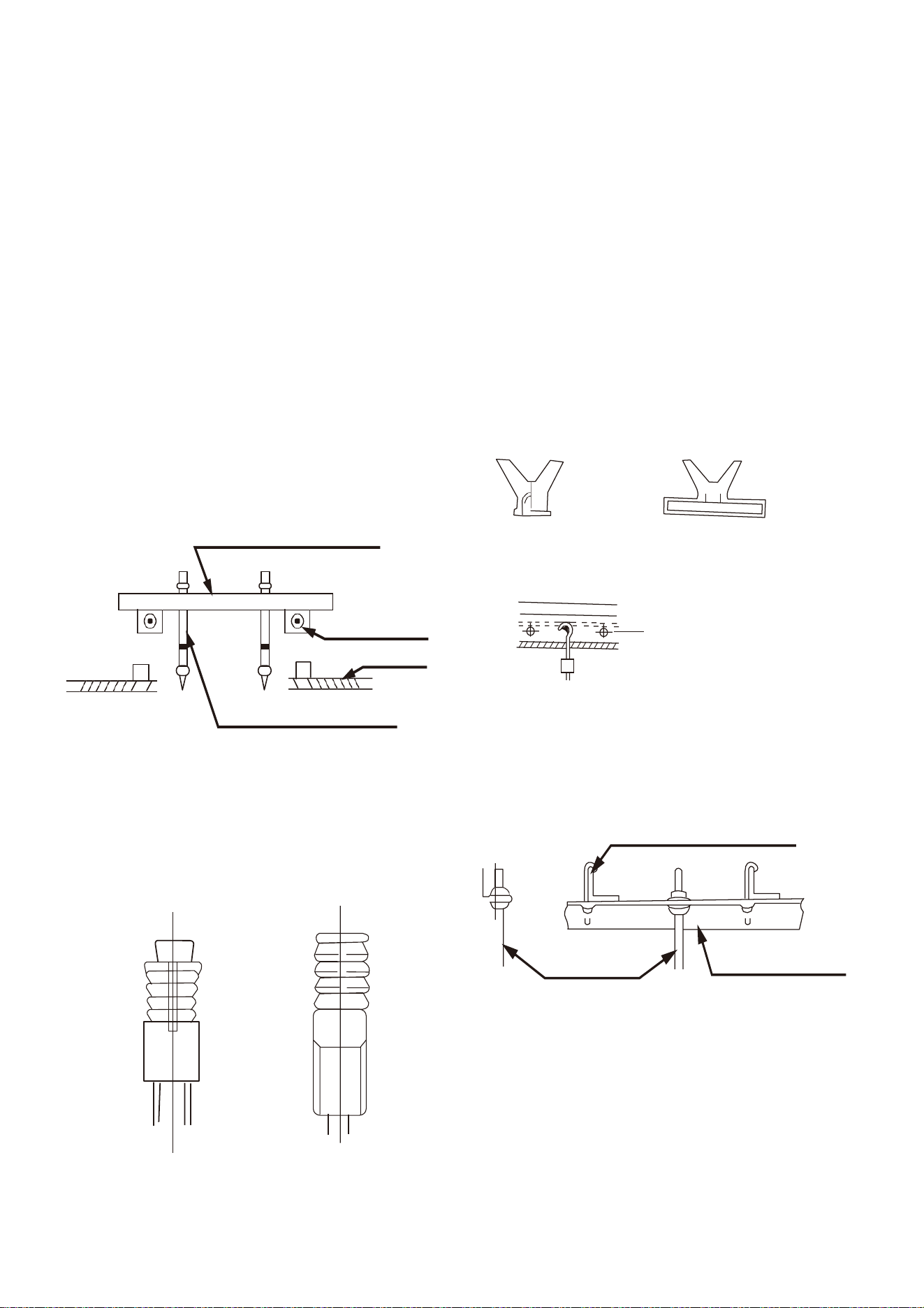
PREPARATION WORK ON THE CEILING
The indoor cassette unit is designed to be supported by 4 x threaded rods, connecting it to a solid
structure above.
The unit must be installed in accordance with current building regulations and the Installation
method should be adjusted depending on the structure of the ceiling. If in any doubt about what
installation method is suitable, independent advice should be sought.
After opening a hole, ensure that the ceiling is horizontal and strong to prevent vibration during
operation. Reinforcement of the ceiling around the opening may be necessary.
If beams require cutting to accommodate the unit, the remaining beams around the area should
be reinforced to compensate for the extra weight they are now supporting.
WOODEN CONSTRUCTION
Fix a square length of timber over the roof
beam and install the hanging screw bolts into it.
Timber over the beam
Roof beam
Ceiling
Hanging Screw Bolt
NEW CONCRETE PANELS
Blade shape
Slide insertion
Steel bar
Pipe hanging and
embedding screw bolt
FINISHED CONCRETE PANELS
Install the hanging hook using expandable bolts
into the concrete to a depth of at least 45mm to
prevent them coming use during operation.
STEEL ROOF BEAM STRUCTURE
Hanging screw bolt
Supporting
Hanging bolts
angle steel
22
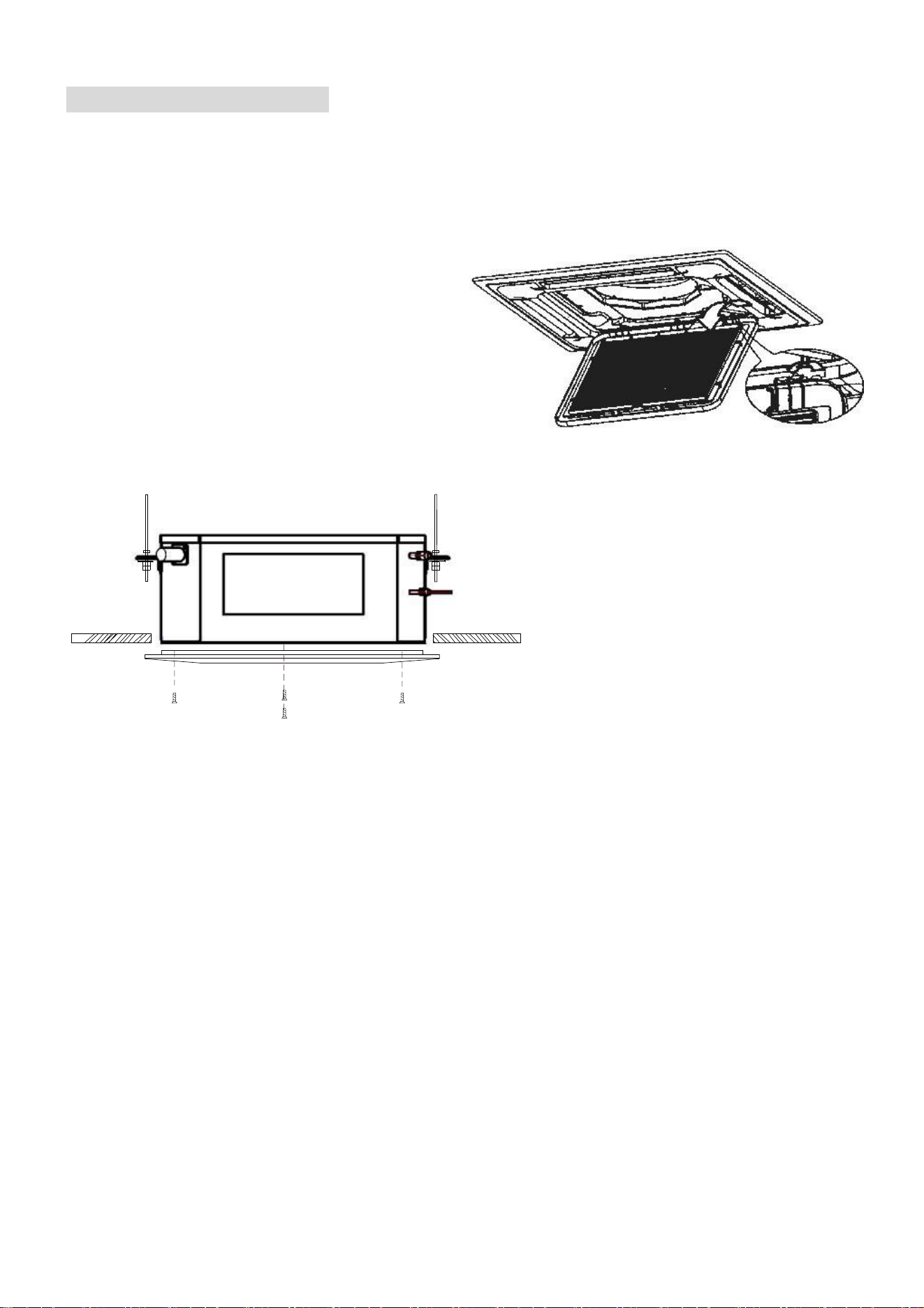
HANGING THE CASSETTE UNIT
WHEN THERE IS NO INSTALLATION POSITION ON THE CEILING
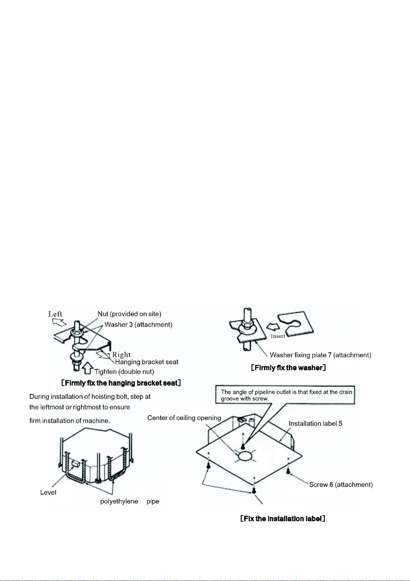
1. Attach the hanging bracket seat to the hoisting bolt; be sure to use bolt and nut separately at
upper and lower head of the hanging bracket seat to firmly fix the hanging bracket seat; use
locating plate 7 to avoid the washer coming-off.
2. For the dimensions of the ceiling opening please refer to the installation drawings. The details
refers to the building agent or carpenter. The indoor unit centre is marked on the attached
installation drawing. As shown in the figure below, the screws 6 (3 pcs) mount the installation
label on the unit; fix the angle of the drain channel at the pipeline outlet with a screw.
3. Adjust the unit to the correct installation position.
4. Check whether the unit is level. The indoor unit is equipped with an embedded drain and float
switch. Check whether the four angles of unit are level.
5. Remove the washer fixing plate 7 ensuring the water-proof washer remains in position and
tighten the upper nut.
6. Remove the installation label.
WHEN THERE IS INSTALLATION POSITION ON THE CEILING
1. Temporarily install the indoor unit Attach the hanging bracket on the hoisting bolts. Be sure
to use bolt and nut separately at upper and lower head of the hanging bracket seat to firmly
fix the hanging bracket seat; use locating plate 7 to avoid the washer coming-off.
2. Adjust the height and position of unit.
23
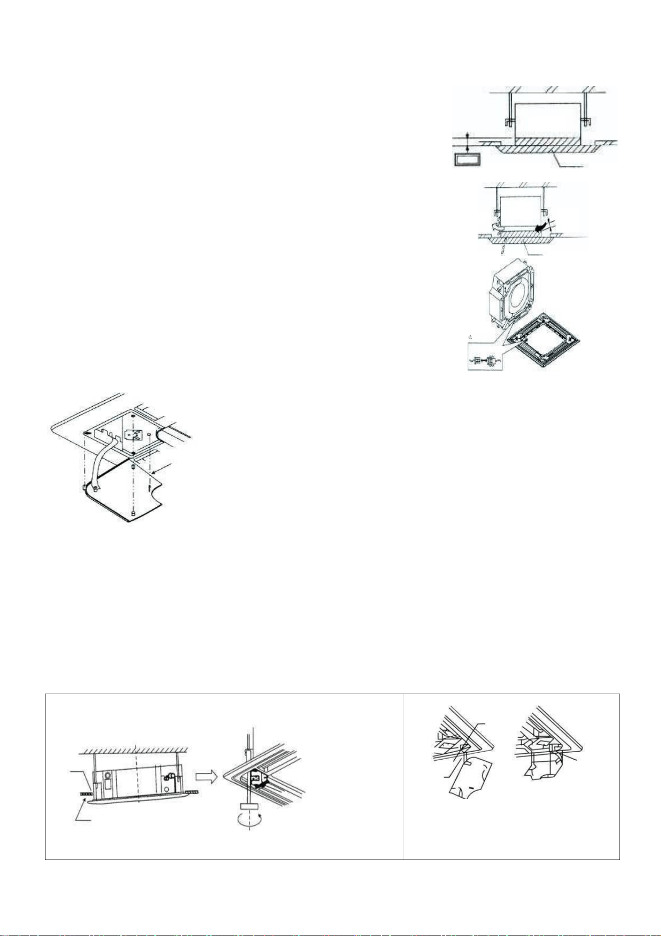
HOISTING HEIGHT OF INDOOR UNIT
Please adjust the hoisting height of indoor unit to make the
dimensions of indoor unit under the ceiling.
1. When there is gap between indoor unit and panel, condensation
may occur.
2. Line of trim panel (see right figure)
a. Connect the cable for the louvre motor (on the trim
panel).
b. If the connector is not connected, the louvres will not
function. Properly connect the joint.
c. Confirm the wires for the louvre motor are not clamped
between indoor unit and trim panel.
INSTALLATION OF AIR RETURN GRATING AND CAP
A. Install the air return grating
B. Install in reverse sequences to "Preparation of trim panel".
1013
Indoor unit
Panel
Install in reverse sequences to "Preparation of trim panel". While
rotating the air return grating, it can be installed in 4 directions. If
necessary to adjust the installation direction of the air return grating
as required by the user, the installation direction can be changed.
1. Firstly hang the air inlet grating onto the panel and then separately connect the connectors
from the louvre motor and control box on panel to related connectors of body.
2. Re-install the air inlet grating in reverse sequence to those when removing the air inlet grating;
3. Re-install the mounting cover plate.
4. Fix the mounting cover plate rope onto the lug (see the right figure); Gently press the mounting
cover plate in the panel.
①
First loosen the
Upper nut
No gap allowed
②
Adjust the
Lower nut
Install the cover plate
When installing the cover plate,
using a self tapping screw
mount the 4 slide fasteners into the
related slots.
~
Cool air
leak
Indoor
unit
Air guidance
clearance
Panel
Locationofindoorunit Attrimplate
24
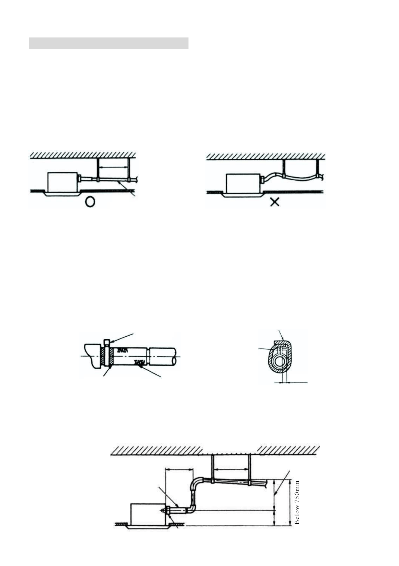
DRAINAGE PIPE INSTALLATION
Please confirm there are enough space at unit installation position to mount the drainage
pipeline, and ensure the drain pipe diameter is no less than that of connection pipe.
(Polyethylene pipe, dimension: 25mm; outer diameter; 32mm)
1. The drain pipe should be short, and the slope of sagging should be equal to and
more than 1%, to. ensure drainage smoothness and avoid condensate lag
2. If impossible to ensure adequate slope for the drainage hose, a drainage lift pipe shall be
installed.
3. To avoid bending of drainage hose, it will keep 1 to 1.5m distance between hanging
bracket.
Slope above 1/100
4. Use the attached drainage pipe ① and clamp ②.
Insert the drainage hose into drainage socket till the white rubber belt. Tighten the clamp
until the distance of screw head from hose is less than 4mm.
5. Condensation may lead to water leak, so it is necessary to fulfil thermal insulation
construction for following two components.
1.
Drainage pipe in room;
2.
The drainage socket refers to the figure below; insulate the thermal for clamp and
drainage pipe with attached large sealing pad ⑩.
Large sealing pad
⑩ (accessories)
Clamp ② (accessories)
Water drain pipe ①
Notice for the drainage lift pipe:
Clamp ②
Below 4mm
(accessories)
1. The installation height of drainage lift pipe shall be less than 550mm.
2. The exhaust lift pipe shall be perpendicular to the unit and be no more than 300mm from the
unit.
Ceiling
Within 300mm
1
-
1.5 m
Hanging bracket seat
Below 550mm
Drainage hose
①
( accessories )
Clamp
②
( accessories )
Drainage lift pipe
200 mm
0.8 to 1 m
Adhesive tape (white)
25
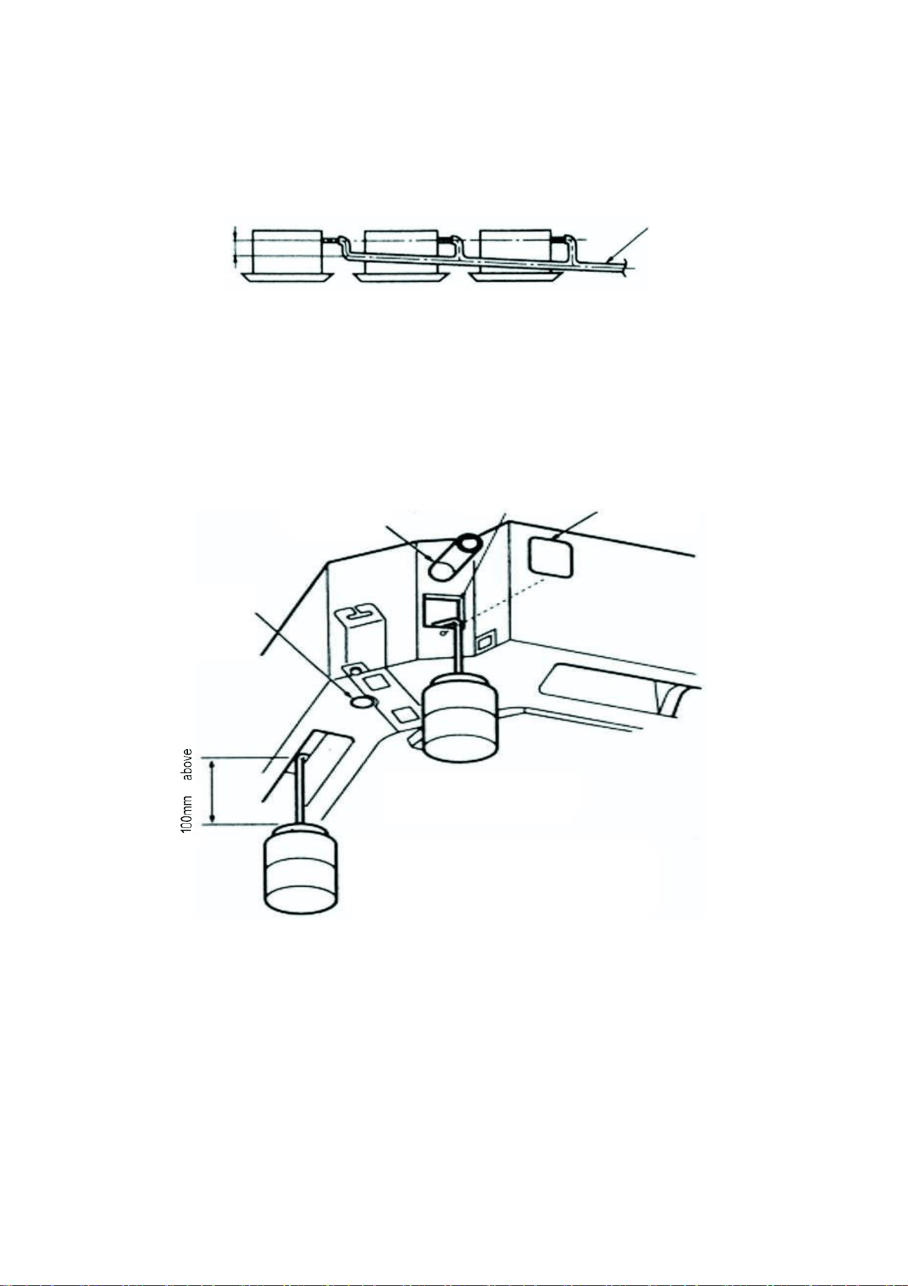
Notes:
1.
Do not make the attached drainage hose subjected to excess force or bending and
twisting. (It may lead to water leak)
2.
Please install according to following procedure if several drainage pipes converge.
T- Joint
converge
drainage pipe
Above 100mm
The specification of selected converge drainage pipe shall be suitable for operation
capacity of unit. After completed the installation, slowly fill 2000cc water in the exhaust
port or inspection hole and check whether the drainage is smooth; after installation of
electric circuit, check the drainage conditions during refrigerant operation and the
detailed instructions refer to "test run". Water injection method
Access hole
Drainage pipe
Inspection hole
Service hood
Drainage outlet for
Maintenance (with rubber
plug)(discharge the water in
( Fill water from inspection hole )
Plastic spraying pot
( The pipe shall be about 100mm long
)
( Injection from exhaust port )
26
PANEL INSTALLATION
The panel should be installed after the pipework and wiring have been connected.
Following installation ensure that the gaps between the panel and the ceiling are sealed to
prevent air and liquid leakage.
1. Push the two grill switched towards the
centre to unhook the grill before pulling the
centre of the panel downwards to remove it
from the panel.
2. Hold the grill at a 45 angle to the unit and lift
to unhook from the rear of the panel.
3. Hold the panel against the cassette
unit, lining up the red arrow on the
electrical box with the one on the
panel, before loosely fastening with
the M6 bolts.
4. Connect the cables for the step
motors and display panel to the
cassette following the wiring diagram
provided, ensuring that the cables will
not get trapped when tightening the
panel.
5. If the optional wired display panel is also to be installed, it should be also be connected to the
cassette at this point.
6. Check the position of the panel before fully tightening the bolts, so that the panel is flush to the
cassette unit.
7. Reattach the Grill to the panel following the reverse of removal.
8. If there is a gap between the panel and the ceiling after tightening the screws, readjust the
height of the cassette, ensuring it is kept level.
27
INSTALLATION OF THE OUTDOOR UNIT
In order to ensure the correct working of the air conditioner, in the choice of installation
location, the following guidelines must be followed:
1.
Upon installation of the outdoor unit, the air discharged outdoors should not return, and
enough space for maintenance must be left around the machine.
2.
The ventilation must be excellent in mounting points, so that the machine can intake and
discharge sufficient air. Make sure there are no obstacles for air inlet and outlet; any
obstacles should be removed.
3.
The installation location is strong enough to withstand the weight of the outdoor unit, and
has the effect of sound insulation and vibration reduction. And to ensure that outlet air
and noise of the unit will not affect the neighbours.
4.
Avoid direct sunlight, it's best to put up an sunshade for protection.
5.
In the mounting position, rain and condensate water must be drained.
6.
In the installation position, it must be ensured that the machine will not be buried in the
snow, and not subject to the effects from garbage and mists.
7.
In the installation position, it must be ensured that the air outlet is not facing the strong
wind.
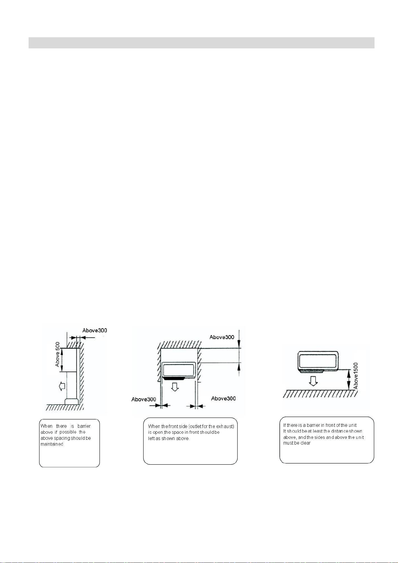
INSTALLATION REQUIREMENTS AND MAINTENANCE SPACE (OUTDOOR UNIT)
1.
Single unit installation (unit: mm)
28
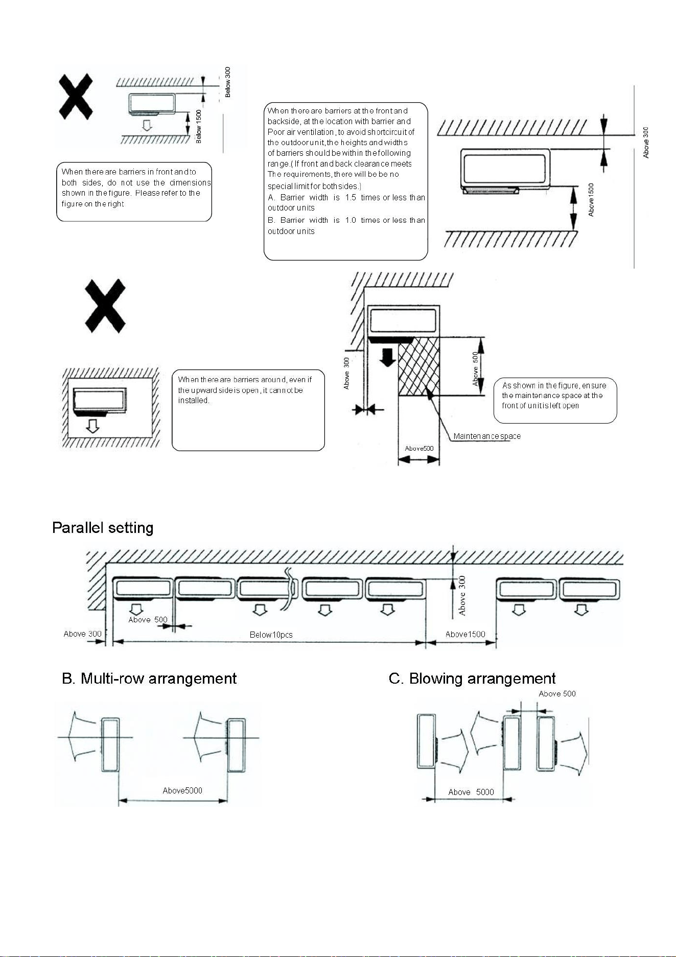
MULTI UNIT INSTALLATION
29
MOUNTING ON A ROOF OR OTHER WINDY POSITIONS
When the outdoor unit is to be mounted on the roof or place around which there is no building, it
is necessary to avoid strong winds directly blowing into the air outlet of the outdoor unit. To avoid
impairing the heating or cooling effect and failure of the outdoor unit heat exchanger due to
inadequate air flow.
A. When there is wall nearby, please locate the air exhaust facing the wall and keep about
500mm distance from the wall.
B. When the air exhaust is affected by strong wind or wind direction, it is necessary to
change the air intake unit position to make the exhaust port perpendicular to the wind
direction.
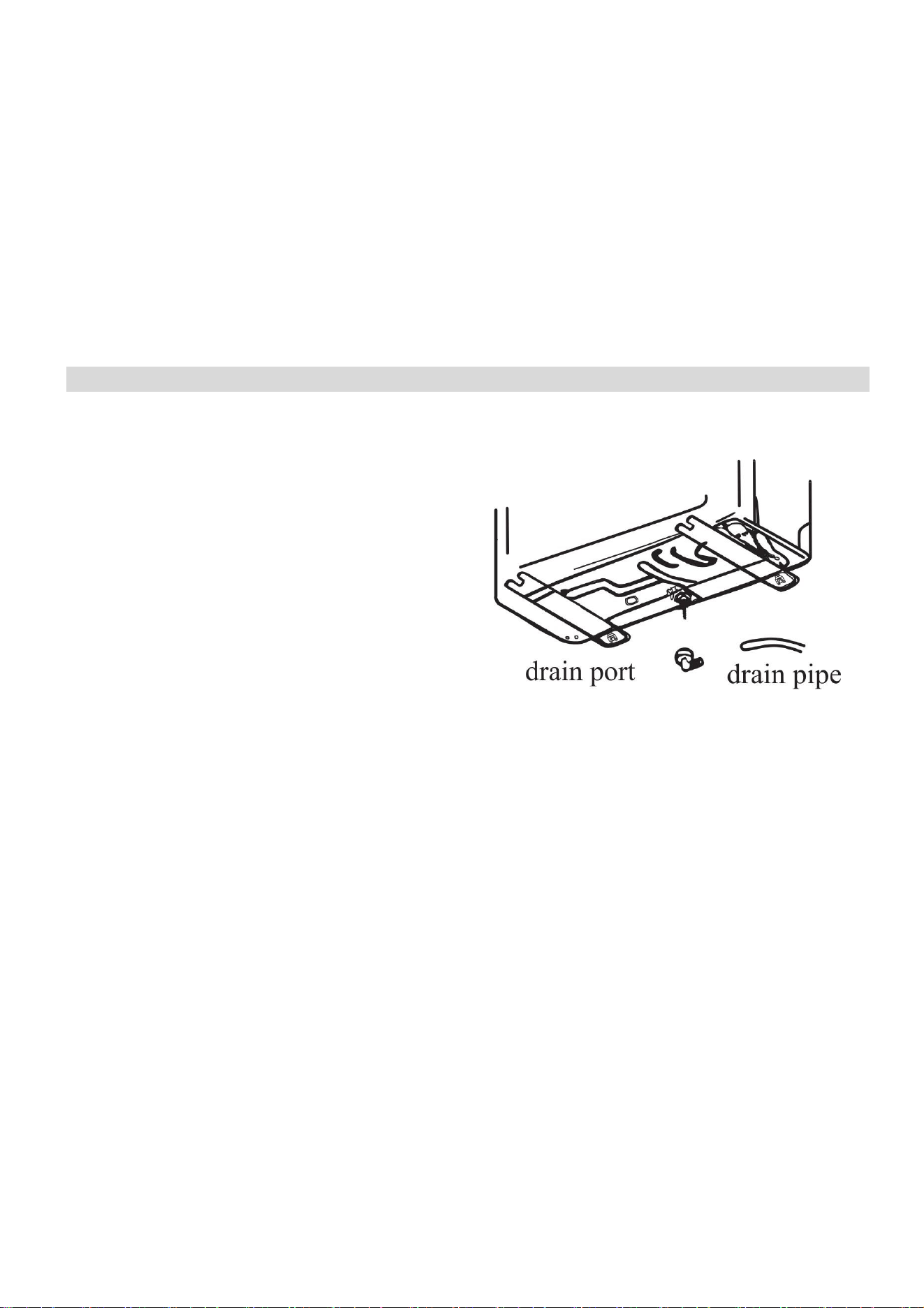
CONDENSATE DRAINAGE OF THE OUTDOOR UNIT
When operating in heating mode condensate
will collect and drain through the base of the
outdoor unit. The air conditioner is supplied with
an elbow joint which can be connected to the
underside of the outdoor unit for drainage.
1. Connect the elbow joint to the drainage hole
on the underside of the outdoor unit.
2. Connect a drain hose (not supplied) to the
elbow joint and run downhill to your chosen
drainage point.
Please note: The drainage is gravity fed, and so
must run downhill.
30
REFRIGERANT PIPE INSTALLATION
Note:
1.
Refrigerant pipe is not supplied with the unit, but a selection are available from the same
retailer as the air conditioner.
2.
A thermal insulation sleeve of more than 9mm thick and with favourable thermal
insulation performance should be used to avoid condensation when selecting the
refrigerant pipe.
3.
When installing the drainage hose (not supplied), additionally procure the cable tray
connection exhaust pipe with inner diameter of φ16, and bind up with the thermal insulation
sleeve of 9mm thick to avoid condensation.
DIMENSION OF REFRIGERANT PIPE
Model
Refrigerant Liquid Pipe
Diameter
Refrigerant Gas Pipe
Diameter
eiQ-CRFC18K
6.4 (1/4”)
12.7 (1/2”)
eiQ-SSRFC24K
9.52 (3/8”)
15.88 (5/8”)
eiQ-SSRFC36K
eiQ-SSRFC48K
eiQ-SSRFC60K
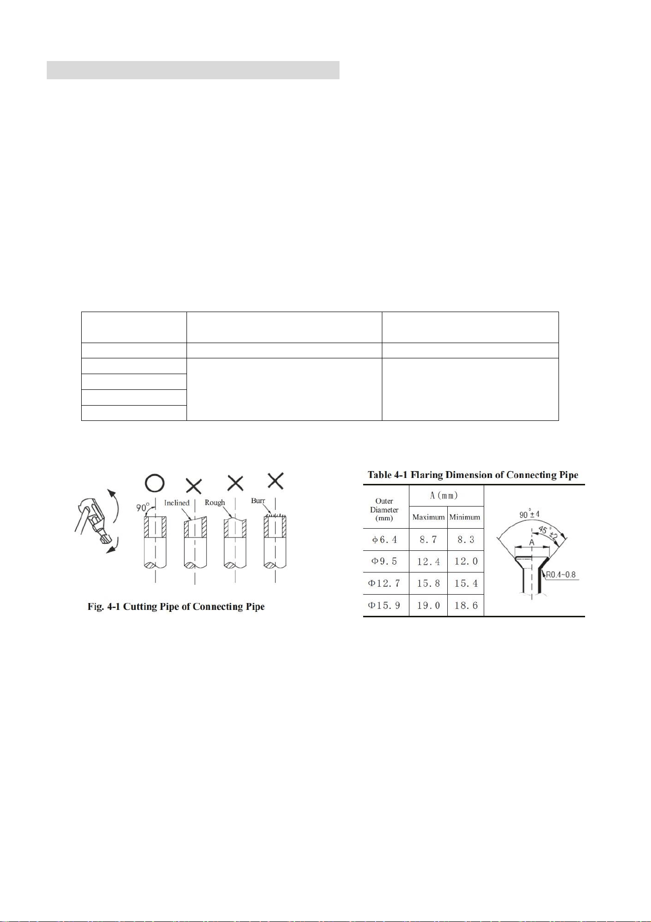
FLARING THE PIPES
31
LENGTH AND HEIGHT DIFFERENCE OF ULTRA-LONG PIPING OF AIR CONDITIONING
UNIT
eiQ-
CRFC18K
eiQ-
SSRFC24K
eiQ-
SSRFC36K
eiQ-
SSRFC48K
eiQ-
SSRFC60K
Max Pipe
Length
15M
20M
50M
50M
50M
Max Height
Difference
8M
10M
20M
20M
20M
Max Pipe
bends
10
10
15
15
15
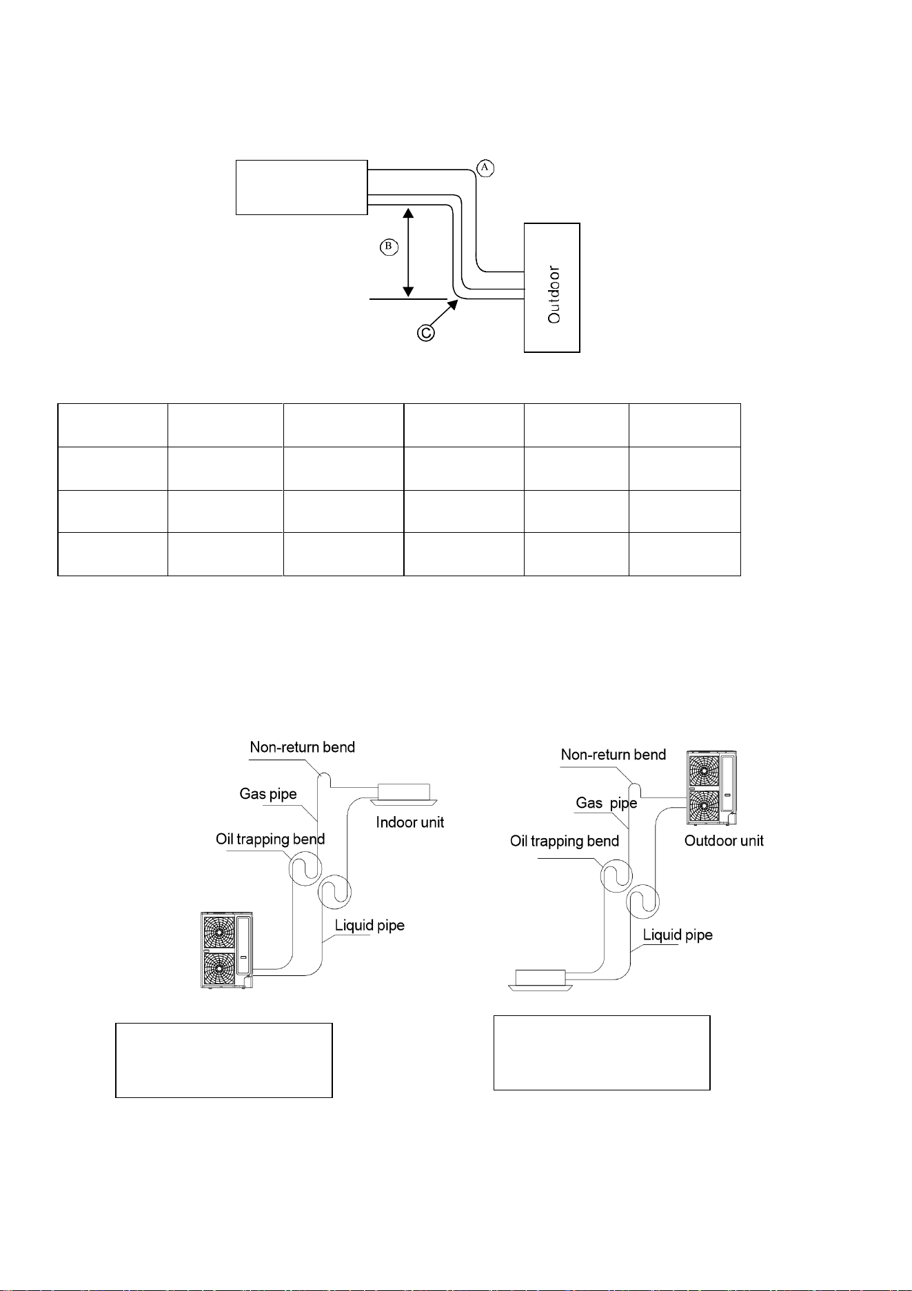
Note: When the height is more than 5m, set the oil trapping bend and non-return bend according
to relative positions of outdoor unit and indoor unit.
Outdoor unit Indoor unit
When the installation position
of indoor unit is higher than
outdoor unit
When the installation position
of indoor unit is higher than
outdoor unit
Indoor unit
32
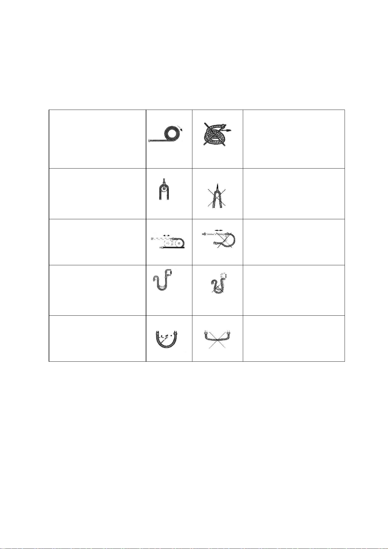
NOTES:
The copper pipe used in the refrigeration lines are very soft, high pressure copper and prone to
get damaged if not handled correctly. Try to avoid bending or stretching the pipework. Always
ensure the pipes are protected when running through the wall to help prevent damage to the
pipes.
To keep the allowed
bending radius please
make the packed soft
pipes vertical before
extending
Please do not extend only
one side of the packed soft
pipes.
Please make use of
semicircle pulley to keep the
allowed bending angle
Extreme bending could
damage the pipes
Please use a twisting
wheel to avoid improper
bending.
Over bent soft pipes will lead
to irregular bending
Please use rigid elbow to
keep the bending angle
while soft pipes operating.
Undersize bending will
damage the soft pipe.
Please keep the minimum
bending angle while
installing
Do not use short sharp
angle bends.
33
STANDARD PIPELINES CONNECTION & AIR PURGING
No dust or any other particles, air or moisture should be allowed to enter the air conditioning
system. Careful attention should be paid when pipeline connection for outdoor unit is made. Try
to avoid repeated curves as much as possible; otherwise damage to the copper pipes may occur.
Suitable wrenches should be used when the pipeline connection is done so as to ensure
appropriate torque (refer to following torque table).
Excessive torque action might damage the joints while too little torque might lead to leakage.
Torque based upon the wrench to be used
Follow the procedures below:
1. Remove the dust caps from the indoor and outdoor units and the connecting pipe.
2. Align the joint of the connecting pipe between the indoor and outdoor and tighten the
connecting nut by hand to prevent cross threading. Secure them with a wrench, applying
the maximum torque as shown in the table above.
3. Pressure test and vacuum pump the pipework for each refrigerant circuit.
4. Remove the two valve core caps from the outdoor unit and turn on the high and low
pressure valve cores with an socket wrench, then tighten the two valve core caps of the
outdoor unit. Finally you can wrap hot insulating tape around the joints of indoor and
outdoor units
Copper pipe diam.
Tightening torque
Strengthened tightening torque
6.35(1/4")
160kgf.cm(63kgf.inch)
200kgf.cm(79kgf.inch)
9.52(3/8")
300kgf.cm(118kgf.inch)
350kgf.cm(138kgf.inch)
12.7(1/2")
500kgf.cm(197kgf.inch)
550kgf.cm(216kgf.inch)
15.88(5/8")
750kgf.cm(295kgf.inch)
800kgf.cm(315kgf.inch)
34
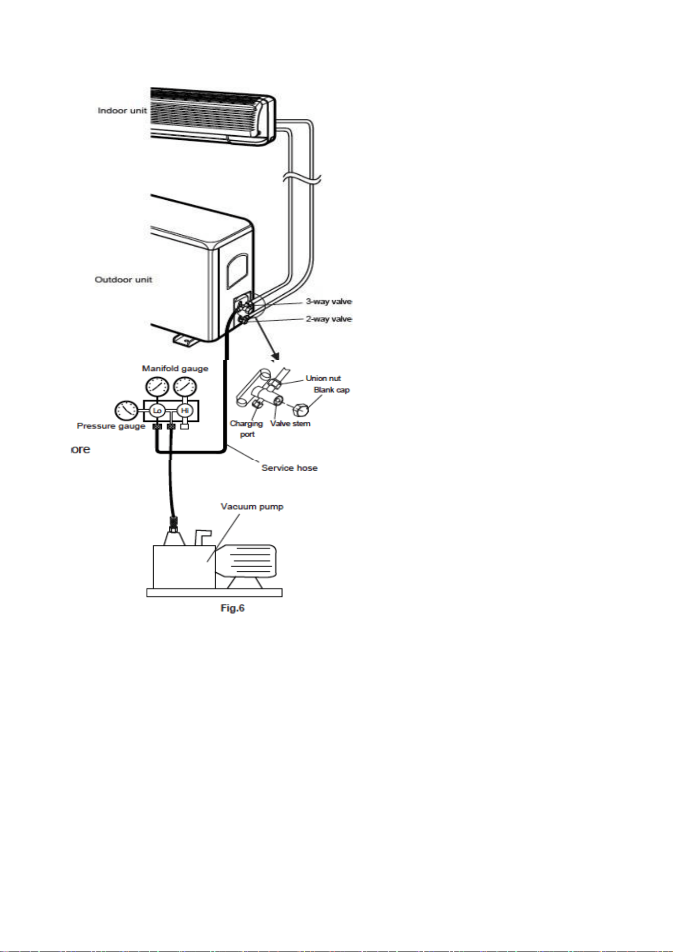
AIR PURGING WITH VACUUM
PUMP
1.
Check that pipelines connection
have been properly connected,
remove the charging port cap, and
connect the manifold gauge and
the vacuum pump to the charging
valve using service hoses as
shown
2.
Open the valve on the low-
pressure side of the manifold
gauge, then run the vacuum
pump. Vacuum the indoor unit and
the connecting pipes until the
pressure in them lowers to below
1.5mmHG (The operation time for
vacuuming is about 10 minutes).
When the desired vacuum is
reached, close the low pressure
valve on the manifold and stop the
vacuum pump.
3.
Disconnect the service hoses and
fit the cap to the charging valve.
4.
Remove the blank caps, and fully
opens the spindles of the 2-way
and 3-ways valves with a service
valve wrench.
5.
Tighten the blank caps of the 2-
way and 3-ways valves, applying
the torque listed in the table
above.
35
PRESSURE TEST, VACUUMING AND LEAK TEST OF CONNECTING PIPE AND
INDOOR UNIT PIPELINE:
After installed the connecting pipe and indoor unit, firstly charge the nitrogen into the
connecting pipe and indoor unit pipe to 3.0Mpa and keep the pressure for 24h; at
same time, check for leaks with soap bubble at the connectors and welding
positions; if no leak detected, discharge the nitrogen and vacuum with a
vacuum pump (the vacuum degree shall be less than 30Pa), and then open the
main machine valve for a test run ; if the refrigerant pipe length is more than 5m,
refill the refrigerant and refer to following table:
eiQ-CRFC18K
eiQ-SSRFC24K
eiQ-SSRFC36K
eiQ-SSRFC48K
eiQ-SSRFC60K
Refrigerant to be
added per metre of
liquid pipework above
5m.
0.012Kg
0.024Kg
0.024Kg
0.024Kg
0.024Kg
i.e. If liquid pipe on an eiQ-SSRFC24K is 7m, amount of refrigerant to be added would be (7 –
5)*0.024Kg, so 0.048kg should be added.
When refilling the refrigerant, use the needle valve on low pressure valve body of
outdoor unit in refrigeration mode.
GAS LEAKAGE INSPECTION
After the pipeline connection is done, use a leakage inspection device to carefully check
if there is any leakage at the joints. This is an important step to ensure the quality of
installation. Once a leak is detected, proper action should be taken immediately.
36
ELECTRICAL CONNECTION OF THE AIR CONDITIONER
The electrical connections can be found under the protective plastic cover. Remove
this from the side of the outdoor unit to gain access to the electrical connections.
Connect the indoor power and control wires with the matching outdoor wire as per
the electrical diagram.
Do not attempt to connect the wires in a different way to the diagram on the air
conditioner as this could damage the unit and invalidate the warranty.
Secure the wires and replace the cover before operating the unit.
The appliance should be installed in accordance with national wiring regulations.
If the supply cord is damaged, it must be replaced by the manufacturer, its service
agent or a suitably qualified person in order to avoid a hazard.
The unit is designed to be hard wired and a suitable switch with a contact separation
of at least 3mm in all poles must be added to the fixed wiring.
The air conditioner electrical wiring must follow the specific country regulations. If
power cord is damaged must be replace by a qualified electrician.
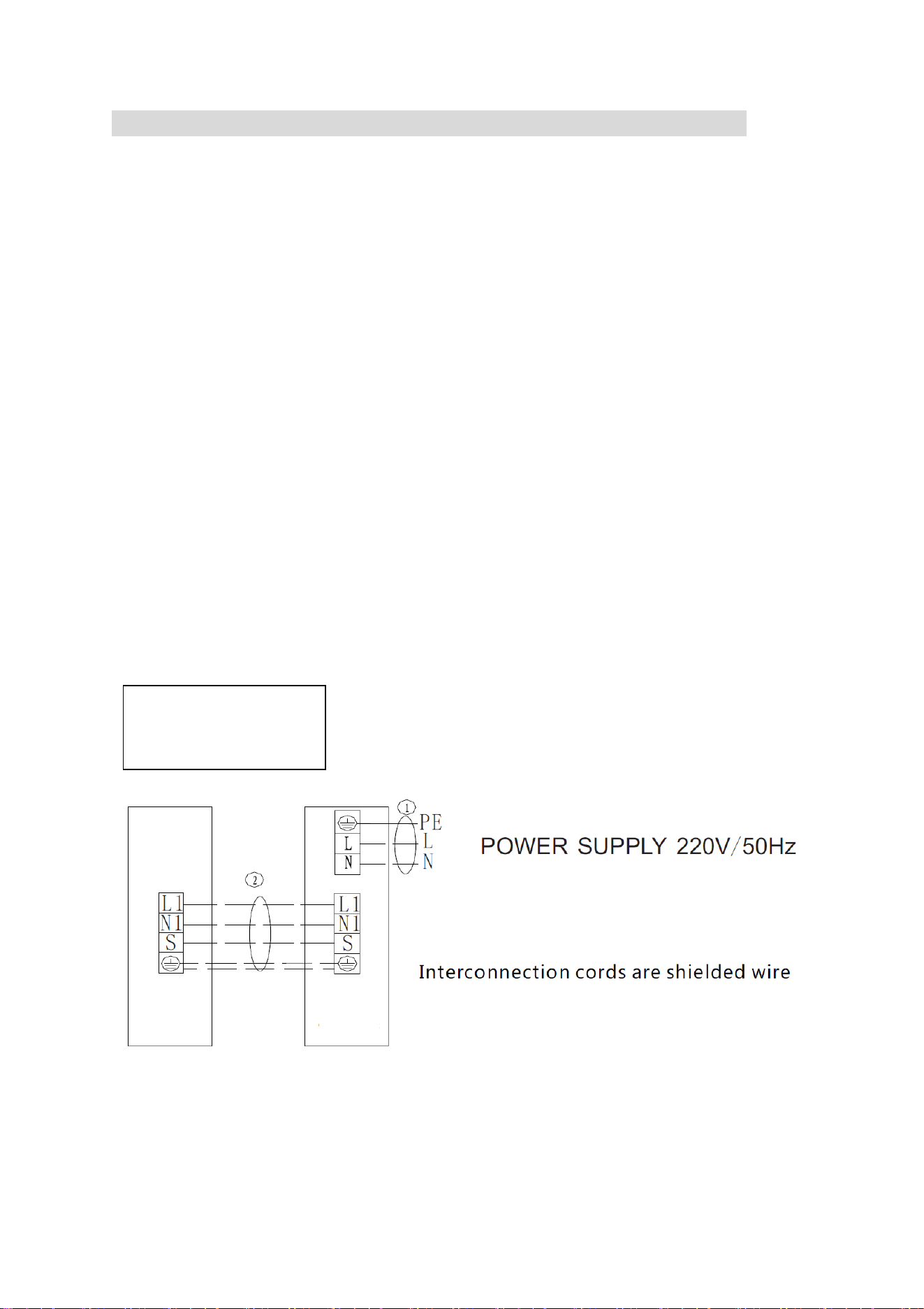
Schematic wiring diagram of power supply (according to user power supply conditions
and different models, execute wiring according to the schematic diagram shown in the
figure below)
eiQ-CRFC18K
eiQ-SSRFC24K
eiQ-SSRFC36K
Indoor
Unit
Outdoor
Unit
37
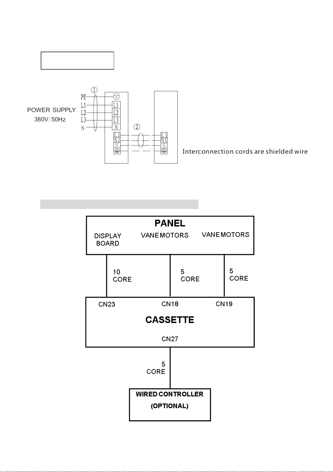
Outdoor
Unit
Indoor
Unit
SIMPLIFIED PANEL WIRING DIAGRAM
eiQ-SSRFC48K
eiQ-SSRFC60K
38
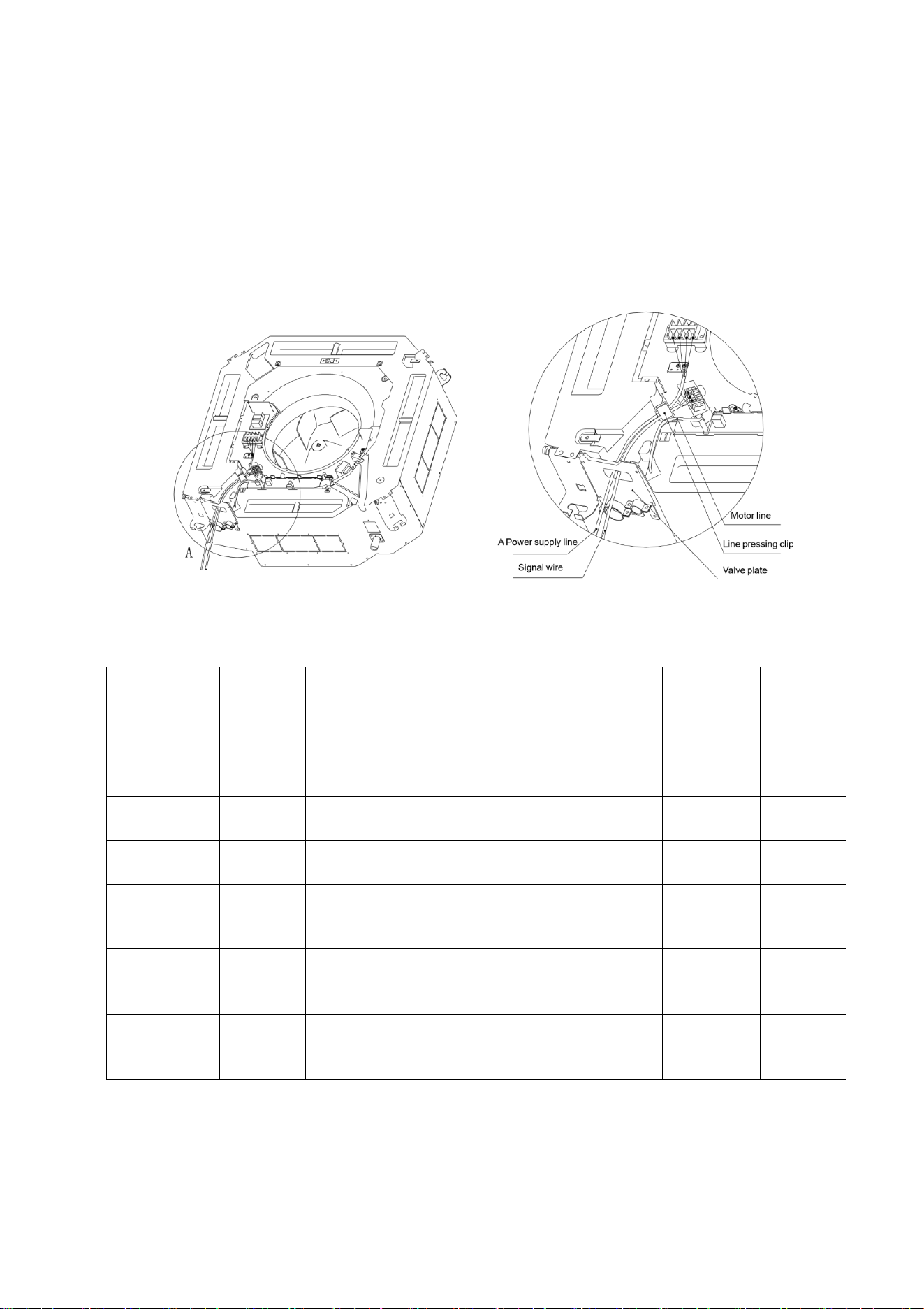
ELECTRIC CONNECTION OF INDOOR UNIT:
1.
Remove the cover plate of indoor unit electric appliance box.
2.
Connect the power supply line and signal line with related terminals ash shown
in the figure.
3.
Open the wire pressing clip, pass the power supply line and signal line through
the valve plate and firmly hold in the pressing clip.
4.
Install the electric appliance box board.
A
Note: Only the wiring methods of signal line and power supply line are shown in in the
figure; the wiring methods please refer to the wiring schematic diagram of power
supply.
Outdoor
Power
Supply
Line
H05RM-
F
Indoor
Power
Supply
Line
H05VV-
F
Indoor /
Outdoor
Connection
Line( no of
Cores,
Diameter)
Power Supply
Method
Outdoor
Min Fuse
(A)
Indoor
Min
Fuse
(A)
eiQ-
CRFC18K
3 x
2.5mm
2
N/A
4 x 2.5mm
2
Outdoor Power
Supply
16
N/A
eiQ-
SSRFC24K
3 x
2.5mm
2
N/A
4 x 2.5mm
2
Outdoor Power
Supply
16
N/A
eiQ-
SSRFC36K
3 x
4.0mm
2
N/A
4 x 2.5mm
2
Outdoor Power
Supply
40
(Single
Phase)
N/A
eiQ-
SSRFC48K
5 x
2.5mm
2
N/A
4 x 2.5mm
2
Outdoor Power
Supply
20
(Three
Phase)
N/A
eiQ-
SSRFC60K
5 x
2.5mm
2
N/A
4 x 2.5mm
2
Outdoor Power
Supply
20
(Three
Phase)
N/A
* For lengths 20 – 50M 3 x 4mm
2
should be used
39
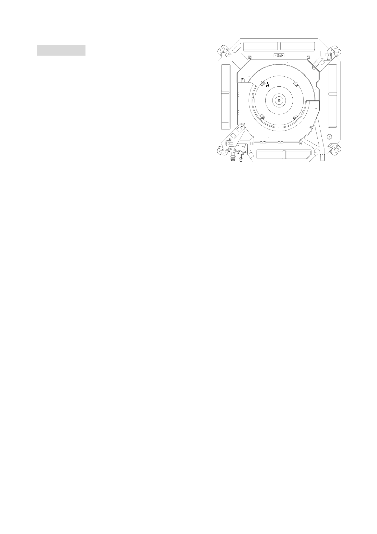
TEST RUN
CONFIRMATION BEFORE TEST RUN
After installation of indoor and outdoor units,
piping and wiring, please confirm there is no
refrigerant leak, loss of power supply line and
signal line, and no mistaken polarity.
Note: The compressor will not run in case of
incorrect connection of the power supply line.
Note: Before test run, be sure to take out 4 air
wheel damper blocks (A) and fixing tape!
TEST RUN
1.
Connect the main power supply of unit.
2.
Press the emergency operation switch (refrigeration or heating) and the air
conditioner starts; the operation indication lamp will illuminate; check whether the
operation of unit is normal; when the emergency operation switch is pressed again, it
will stop the operation.
3.
Press the "ON/OFF" button on the remote control and confirm whether the indoor
unit emits a sound; if heard, the remote control functions and the emergency
operation will be canceled; then operate the buttons of remote controller to observe
whether the operation modes of unit changes correspondingly.
A.
Press "mode" key and select "air supply" mode; check whether there is air
blowing out from the airconditioner.
B.
Press "mode" key and select refrigeration mode; check whether there is cool
air blowing out of the airconditioner.
C.
Press "mode" key and select heating mode; check whether there is hot air
flowing out of the airconditioner (without this mode for single cold type unit)
D.
Press "wind speed" mode and select high speed mode; check whether there
is strong wind blowingout of the air conditioner.
E.
Press the "swing" mode, and observe if wind grate is normal swing.
TEST THE DRAINAGE DEVICE
1.
After installation of the unit, it is necessary to check the drainage device.
2.
During test run, it is necessary to correctly drain out and ensure no leak of connector.
After installation and test run, the installation personnel shall introduce the operation
method and safety notices to the user according to the operation instructions.
40
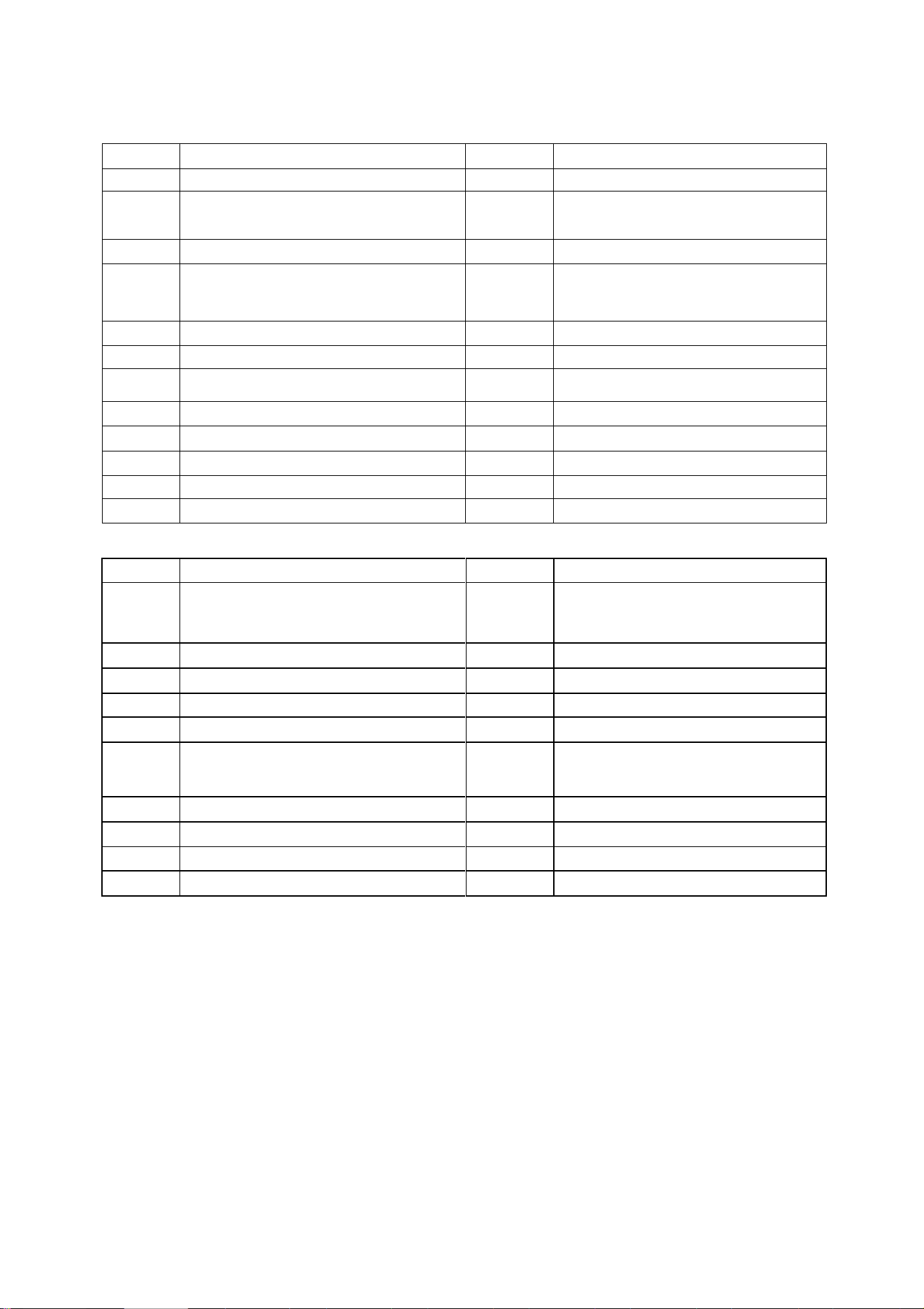
TROUBLESHOOTING AND SELF DIAGNOSIS
MALFUNCTION
POSSIBLE CAUSE
The appliance
does not
operate
Power failure
Damaged indoor/outdoor unit fan motor
Faulty compressor thermomagnetic circuit breaker
Faulty protective device or fuses
Loose connections
Self protection in adverse conditions
Voltage higher / lower than the voltage range
Active TIMER-ON function
Damaged electronic control board
Strange odour
Air filter dirty
Noise of running
water
Back flow of liquid in the refrigerant circulation
A fine mist
comes from
the air outlet
This occurs when the air in the room becomes very cold, for example
in the COOLING or DEHUMIDIFYING modes.
A strange noise
can be heard
This noise is made by the expansion or contraction of the front panel
due to variations in temperature and does not indicate a problem.
Insufficient
airflow, either
hot or cold
Inappropriate temperature setting.
Air inlet or outlet of indoor or outdoor unit has been blocked.
Air filter is blocked.
Fan speed set at minimum.
Other sources of heat in the room.
No refrigerant.
The appliance
does not
respond to
commands
Remote control is not near enough to indoor unit.
Battery in Remote controller may have been exhausted..
Obstacles between remote control and signal receiver in indoor unit.
The display is
off
Active LED function
Power failure
Remote cannot
select heating
mode.
Remove the batteries from the remote and follow the guide for
setting up the remote.
Switch off the air conditioner immediately and cut off the power supply in the
event of:
Strange noises during operation.
Faulty electronic control board
Faulty fuses or switches.
Spraying water or objects inside the appliance.
Overheated cables.
Very strong smells coming from the appliance.
41
SELF DIAGNOSIS FUNCTION
Table 1: Failure code list of indoor unit
Fault Description
4LED fault indication
Digital display
Wired remote display
Three-phase power phase sequence fault
E0
E0
Indoor and outdoor unit communication failure
Timing lights flash
E1
E1
Temperature sensor (T1) fault
Running lights flash
E2
E2
Pipe temperature sensor in the evaporator (T2) fault
Running lights flash
E3
E3
Pipe temperature sensor in the evaporator (T2B) fault
Running lights flash
E4
E4
Outdoor unit failure
Warning lights flash slowly
E5
E5
The indoor unit EEPROM fault
Defrost lights flash slowly
E7
E7
Water over protection
Warning lights flash
EE
EE
Indoor unit with line controller communication failure
E9
E9
Note: The flash frequency for each of the above indicator is 2.5Hz, slow flashing frequency is 1Hz
Table 2: Parameter table for spot inspection of outdoor unit
The digital tube display the indoor unit amount connected and communicated with during standby
The digital tube displays the frequency value during operation of compressor; the digital tube
displays"dF" during defrosting;
Spot check
NO.
Content
Spot check
NO.
Content
1
Indoor unit capacity
11
Opening of EXV
2
Indoor unit capacity demand
12
Running frequency of
compressor
3
Indoor demand after T4 amendment
13
Primary voltage/4
4
Indoor demand after T2 amendment
5
Indoor room temperature (T1)
temperature
6
Indoor coil middle temperature (T2)
temperature
7
Indoor coil outlet temperature (T2B)
temperature
8
Outdoor unit condenser outlet (T3)
temperature
9
Outdoor temperature (T4) temperature
10
Compressor top temperature (T5)
temperature (maximum 99
℃
)
42
Table 3: Failure code list of outdoor unit
Display
Error description
Display
Error description
E0
Phase protection
F0
(reserved)
E1
Communication error between outdoor unit and
indoor unit
F1
(reserved)
E2
Indoor room temperature (T1) sensor error
F2
(reserved)
E3
Indoor coil middle temperature (T2) sensor error
F3
Outdoor unit current error cannot recover
Display P3 error for 3 times within 60
minutes
E4
Indoor coil outlet temperature (T2B) sensor error
F4
Outdoor temperature (T4) sensor error
E5
Outdoor unit error
F5
(reserved)
E6
Zero speed protection
F6
Outdoor unit condenser outlet (T3) sensor
error
E7
EERPOM error
F7
Secondary side current protection
E8
Indoor fan motor speed lose protect ion
F8
Heat T2 temp. protection
E9
Wired controller communication error
F9
Outdoor unit voltage error
EE
Water level alarm error
EF
(reserved)
Display
Error description
Display
Error description
P0
(reserved)
H0
Communication error between outdoor
unit main
board and driver board
P1
(reserved)
H1
(reserved)
P2
(reserved)
H2
(reserved)
P3
Primary/secondary overcurrent protection
H3
(reserved)
P4
Exhaust temperature over-high protection
H4
3 times of P6 error within 30 minutes
P5
Outdoor unit condenser outlet (T3)
temperature
over-high protection
H5
3 times of P2 error within 30 minutes
P6
Compressor driver error or IPM protection
H6
3 times of P4 error within 100 minutes
P7
(reserved)
H7
(reserved)
P8
(reserved)
H8
(reserved)
P9
Outdoor unit DC fan motor error
H9
2 times of P9 error within 10 minutes
43
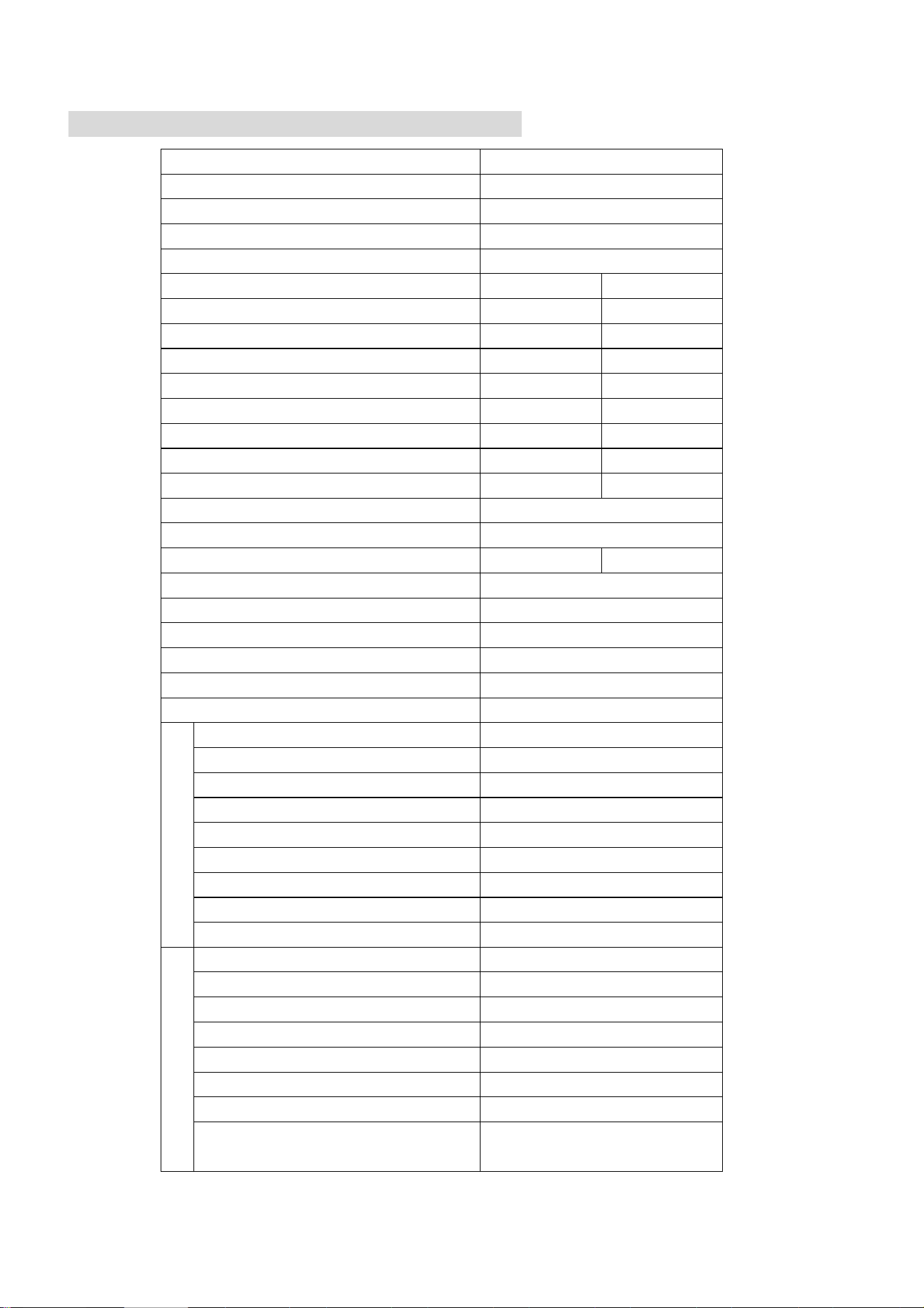
TECHNICAL SPECIFICATION
Model
eiQ-CRFC18K-V4
Indoor Rated voltage and frequency (Ph-V-Hz)
N/A
Outdoor Rated voltage and frequency (Ph-V-Hz)
1Ph/220-240V~/50Hz
Indoor Fuse Required
N/A
Outdoor Fuse Required
16A
Mode
Cooling
Heating
Rated capacity (KW)
5.3 (2.0-5.6)
5.9 (2.5-6.0)
Power input (W)
1555 (420-2100)
1445 (500-1940)
Current input (A)
2.1-10.1
2.5-9.2
SEER/SCOP(W/W)
6.1 / A++
4.0 / A+
Nominal load (kW)
5.300
4.800
Balance point temperature heating (
o
C)
-
-7
Min. outdoor operating temperature (
o
C)
-15
-15
Thermostat-off mode (W)
45
11
Standby mode (W)
1
Off mode (W)
1
Annual consumption (kW)
319
1765
Copper Pipe Type length
-
Liquid side / Gas side (mm/inch)
Φ6.35/Φ12.7
Max. refrigerant pipe length
15
Max. elevation
8
Interconnecting Cable
4x2.5mm
2
Moisture Removal (L/h)
2.47
Indoor
Air Flow (m
3
/h)
650
Body Dimensions (L*W*H) (mm)
565x267x565
Panel Dimensions (L*W*H) (mm)
650x29.8x650
Body Packaging (L*W*H (mm)
745x375x675
Panel Packaging (L*W*H (mm)
750x95x750
Body Net / Gross weight (Kg)
16.5/21.5
Panel Net / Gross weight (Kg)
2.7/4.0
Noise – Sound pressure level (dB/A)
36-43
Noise – Sound power level (dB/A)
46-55
Outdoor
Dimension (L*W*H) (mm)
925x366x700
Packaging (L*W*H) (mm)
990x410x770
Net / Gross Weight (Kg)
45/48
Noise – Sound pressure level (dB/A)
52
Noise – Sound power level (dB/A)
63
Refrigerant type/weight
R32 / 1300g
Defrost mode
Automatic defrosting
Applicable climate types
Cooling (-15
o
C – 50
o
C)
Heating(-15
o
C – 30
o
C)
Due to continuous product development process specification may change.
These units contain a gas governed by F-Gas regulations. The gas must be handled by qualified F-Gas engineers.
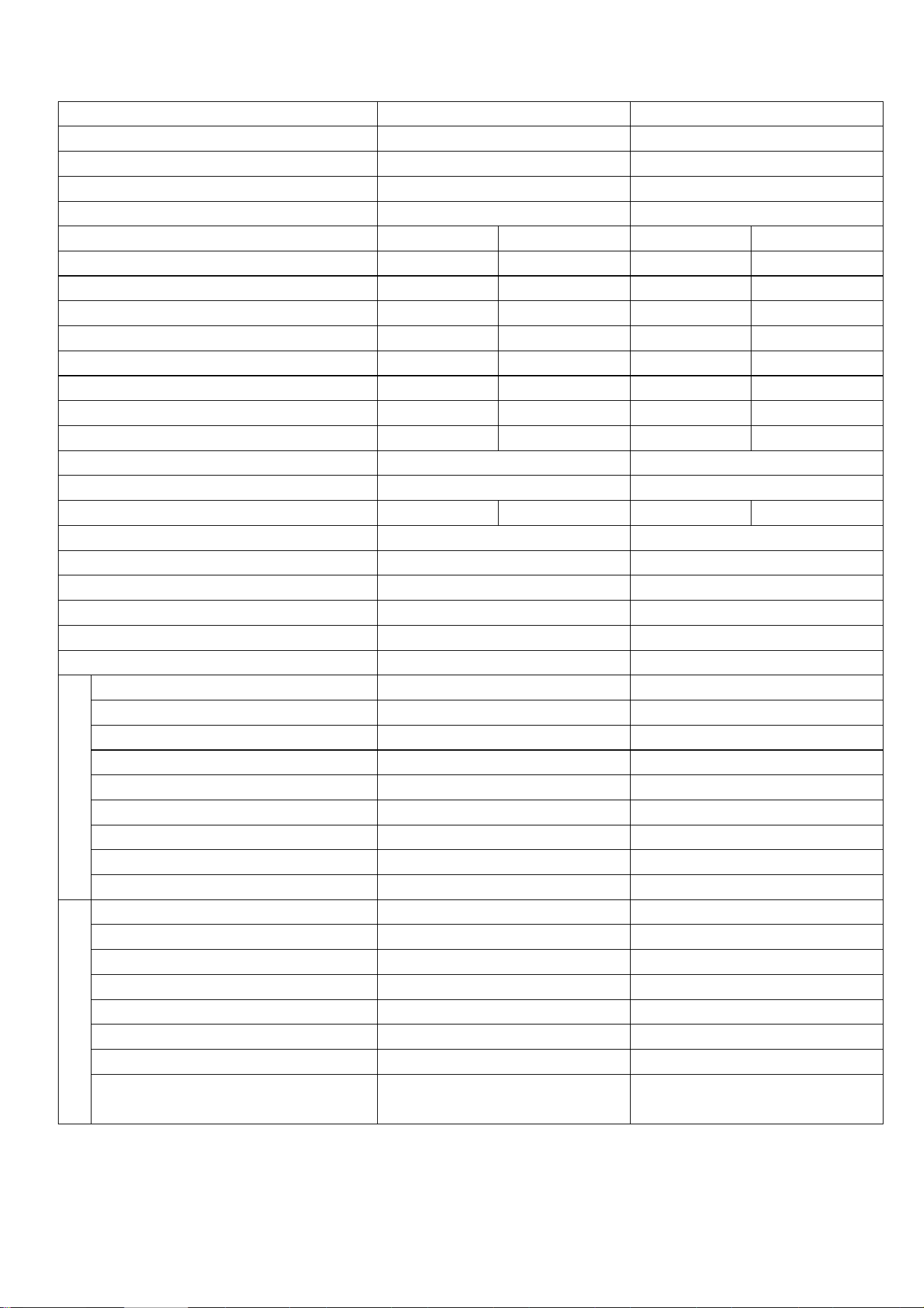
44
Model
eiQ-SSRFC24K-V4
eiQ-SSRFC36K-V4
Indoor Rated voltage and frequency (Ph-V-Hz)
N/A
N/A
Outdoor Rated voltage and frequency (Ph-V-Hz)
1Ph/220-240V~/50Hz
1Ph/220-240V~/50Hz
Indoor Fuse Required
N/A
N/A
Outdoor Fuse Required
16A
40A
Mode
Cooling
Heating
Cooling
Heating
Rated capacity (KW)
7.0 (3.5-8.0)
7.7(4.5-8.5)
10.5 (6.6-12.8)
11.5(7.35-13.2)
Power input (W)
2140 (600-3000)
1920 (1500-2600)
3150 (740-3900)
3375 (1100-4000)
Current input (A)
2.5-13
5.5-11
2.8-20
4.2-20.4
SEER/SCOP(W/W)
6.1 / A++
4.0 / A+
6.1 / A++
4.0 / A+
Nominal load (kW)
7.000
6.000
10.500
7.500
Balance point temperature heating (
o
C)
-
-7
-
-7
Min. outdoor operating temperature (
o
C)
-15
-15
-15
-15
Thermostat-off mode (W)
45
45
45
45
Standby mode (W)
1
1
Off mode (W)
1
1
Annual consumption (kW)
423
2512
610
3080
Copper Pipe Type length
-
-
Liquid side / Gas side (mm)
Φ9.52/Φ15.88
Φ9.52/Φ15.88
Max. refrigerant pipe length
20
65
Max. elevation
10
30
Interconnecting Cable
4 x 2.5mm
2
4 x 2.5mm
2
Moisture Removal (L/h)
2.59
3.51
Indoor
Air Flow (m
3
/h)
1100
1800
Body Dimensions (L*W*H) (mm)
840x230x840
840x285x840
Panel Dimensions (L*W*H) (mm)
950x50x950
950x50x50
Body Packaging (L*W*H (mm)
920x265x920
920x310x920
Panel Packaging (L*W*H (mm)
1030x100x1030
1030x100x1030
Body Net / Gross weight (Kg)
25/30
30.5/36
Panel Net / Gross weight (Kg)
6.5/9.5
6.5/9.5
Noise – Sound pressure level (dB/A)
43-49
43-48
Noise – Sound power level (dB/A)
56-63
53-61
Outdoor
Dimension (L*W*H) (mm)
958x843x392
1030X788X432
Packaging (L*W*H) (mm)
1025x960x430
1120X900X485
Net / Gross Weight (Kg)
52/62
68/74
Noise – Sound pressure level (dB/A)
54
55
Noise – Sound power level (dB/A)
67
68
Refrigerant type/weight
R32 / 1700g
R32 / 2150g
Defrost mode
Automatic defrosting
Automatic defrosting
Applicable climate types
Cooling (-15
o
C – 50
o
C)
Heating(-15
o
C – 30
o
C)
Cooling (-15
o
C – 50
o
C)
Heating(-15
o
C – 30
o
C)
Due to continuous product development process specification may change.
These units contain a gas governed by F-Gas regulations. The gas must be handled by qualified F-Gas engineers.
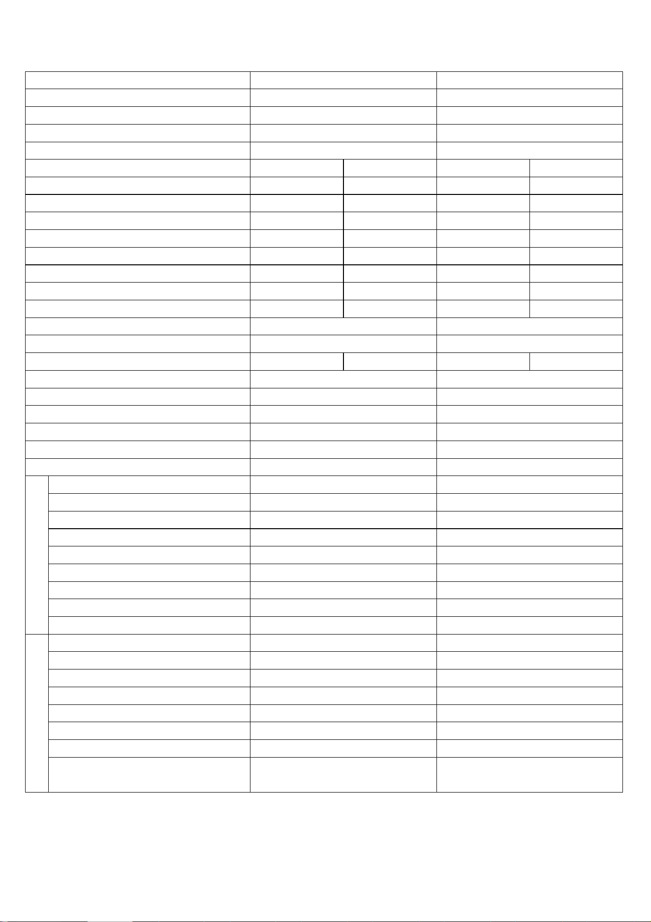
45
Model
eiQ-SSRFC48K-V4
eiQ-SSRFC60K-V4
Indoor Rated voltage and frequency (Ph-V-Hz)
N/A
N/A
Outdoor Rated voltage and frequency (Ph-V-Hz)
380~415/3/50
380~415/3/50
Indoor Fuse Required
N/A
N/A
Outdoor Fuse Required
20A
20A
Mode
Cooling
Heating
Cooling
Heating
Rated capacity (KW)
14.0 (7.0-15.5)
15.2 (8.0-16.0)
16.0(7.5-17.0)
16.8 (8.5-17.5)
Power input (W)
4950 (1100-5800)
4920 (1200-6000)
5900 (1400-6300)
5460 (1500-6500)
Current input (A)
2.8-14.6
3.0-15.0
3.5-15.8
3.7-16.3
SEER/SCOP(W/W)
6.1 / A++
4.0 / A+
6.1 / A++
4.0 / A+
Nominal load (kW)
14.000
11.500
16.000
12.000
Balance point temperature heating (
o
C)
-
-7
-
-7
Min. outdoor operating temperature (
o
C)
-15
-15
-15
-15
Thermostat-off mode (W)
101
23.9
128
23.6
Standby mode (W)
3
3
Off mode (W)
3
3
Annual consumption (kW)
795
3723
911
4046
Copper Pipe Type length
-
-
Liquid side / Gas side (mm/inch)
Φ9.52/Φ15.88
Φ9.52/Φ15.88
Max. refrigerant pipe length
65
65
Max. elevation
30
30
Interconnecting Cable
4 x 2.5mm
2
4 x 2.5mm
2
Moisture Removal (L/h)
5.08
7.96
Indoor
Air Flow (m
3
/h)
1900
2000
Body Dimensions (L*W*H) (mm)
840x285x840
840x285x840
Panel Dimensions (L*W*H) (mm)
950x50x950
950x50x950
Body Packaging (L*W*H (mm)
920x310x920
920x310x920
Panel Packaging (L*W*H (mm)
1030x100x1030
1030x100x1030
Body Net / Gross weight (Kg)
29/34
29/34
Panel Net / Gross weight (Kg)
6.5/9.5
6.5/9.5
Noise – Sound pressure level (dB/A)
45-52
45-52
Noise – Sound power level (dB/A)
56-63
56-63
Outdoor
Dimension (L*W*H) (mm)
1014x1430x450
1014x1430x450
Packaging (L*W*H) (mm)
1095x485x1545
1095x485x1545
Net / Gross Weight (Kg)
109/123.6
112/126.6
Noise – Sound pressure level (dB/A)
58
58
Noise – Sound power level (dB/A)
70
70
Refrigerant type/weight
R32 / 3800g
R32 / 3800g
Defrost mode
Automatic defrosting
Automatic defrosting
Applicable climate types
Cooling (-15
o
C – 50
o
C)
Heating(-15
o
C – 30
o
C)
Cooling (-15
o
C – 50
o
C)
Heating(-15
o
C – 30
o
C)
Due to continuous product development process specification may change.
These units contain a gas governed by F-Gas regulations. The gas must be handled by qualified F-Gas engineers.
46
APPENDIX
Disposal: Do not dispose this product as unsorted municipal waste. Collection
of such waste must be handled separately as special treatment is necessary.
Recycling facilities are now available for all customers at which you can
deposit your old electrical products. Customers will be able to take any old
electrical equipment to participating sites run by their local councils. Please
remember that this equipment will be further handled during the recycling
process, so please be considerate when depositing your equipment. Please
contact the local council for details of your local household waste recycling
centres.
47
We recommend that you note the details of your purchase below and retain your original
proof of purchase receipt with this manual. Keep these documents safe in the event of a
warranty claim.
Purchase Date:
Retailer name:
Model number:
Serial number:
Installation Date:
Installer name:
Service Date:
Engineer/ Company name:
electriQ UK SUPPORT
Please, for your own convenience, check the troubleshooting guide before calling the service line.
If the unit still fails to operate call: 0871 620 1057 or complete the online form Office hours:
9AM - 5PM Monday to Friday
www.electriQ.co.uk/support
Unit J6, Lowfields Business Park
Lowfields Way, Elland
West Yorkshire, HX5 9DA
WARRANTY INFORMATION
electriQ guarantee provides cover against material or manufacturing faults.
This means that if your air conditioner develops a fault during the guarantee
period, we will arrange for it to be repaired or replaced.
Faults arising from a faulty installation are specifically excluded.
The system must be serviced annually by qualified personnel.
This unit must be operated under conditions as recommended in this user manual,
at voltages indicated on the unit. Any attempts made to service or modify the unit
by unqualified person, will render this WARRANTY VOID.
This warranty is in addition to, and does not affect, your statutory rights.
Our warranty is RTB warranty and cover parts and labour only.