Visit Our Website
SCAN ME
PyleUSA.com
USER GUIDE
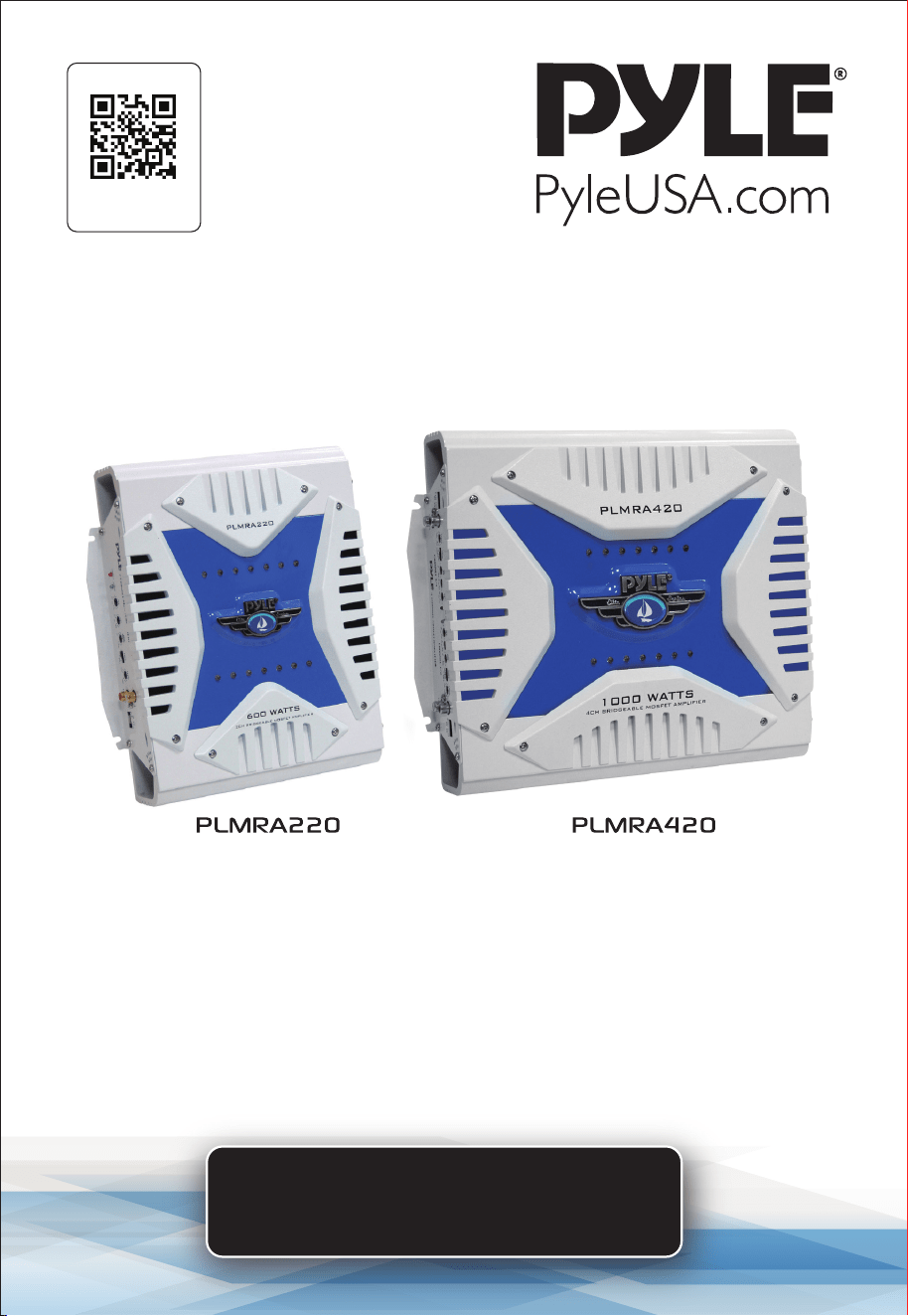
Waterproof Marine Bridgeable Amplifier
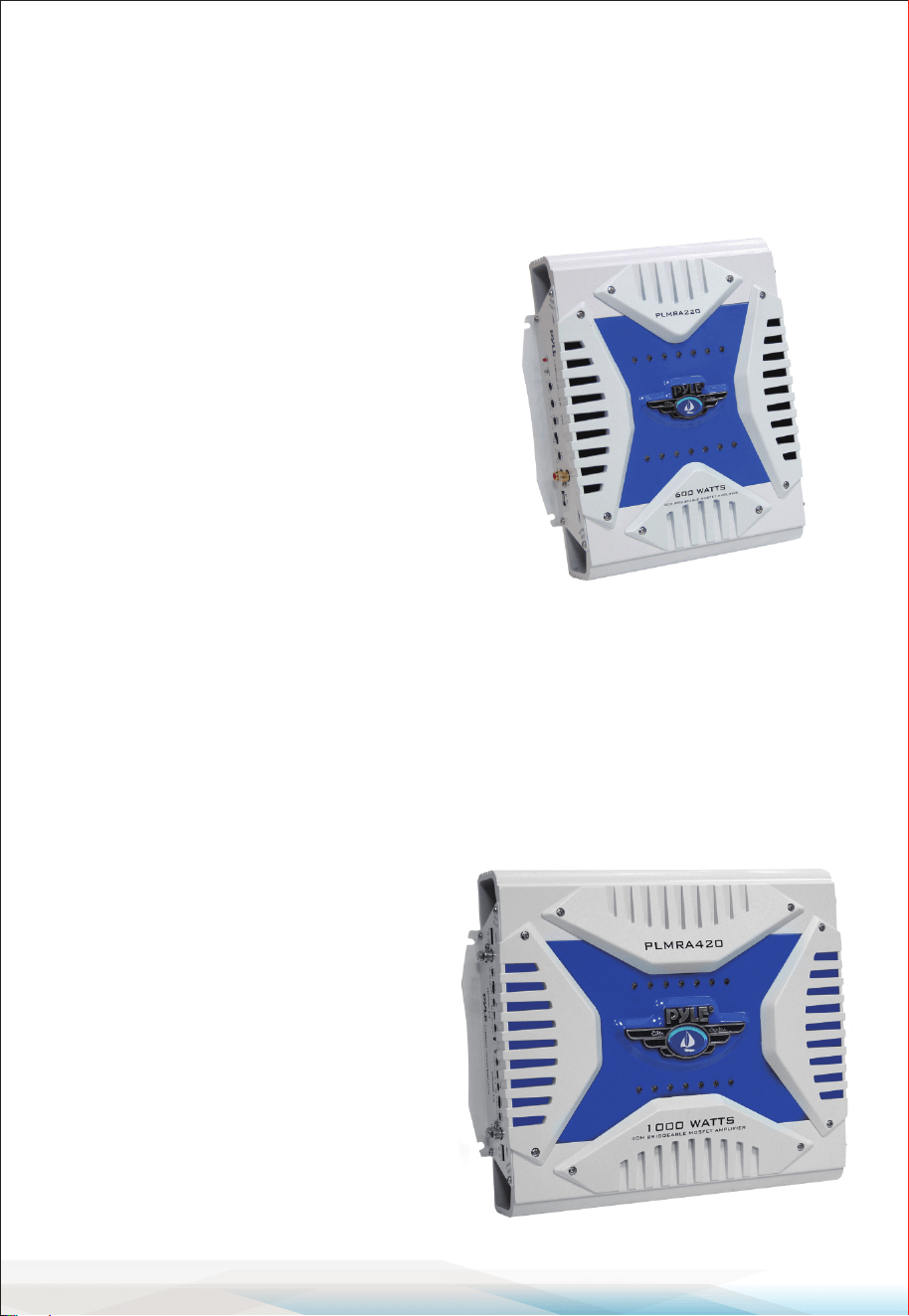
PLMRA220 - PLMRA420

www.PyleUSA.com
2
About PyleUSA
Pyle, founded in the 1960s, has evolved into a renowned manufacturer
of high-quality advanced woofers. Our journey started with the iconic
Pyle Driver, becoming a household name in original speakers. In the late
20th century, we expanded into replacement speakers, car audio, home
audio, marine audio, and professional audio & musical instruments with
our Pyle Pro line.
Pyle Car:
Transform your car into a perfect listening environment with our c
ompetitively priced speakers, ampliers, and head units. Upgrade from
factory speakers to enhance your music experience. Explore accessories
like navigation systems, DVD players, iPod interfaces, and safety-focused
cameras.
Pyle Home:
Discover a range of home entertainment products, including projectors,
TVs, mounts, stands, and HD technology. Pyle Home oers bass-expanding
mini speakers, headphones, vintage turntables, power ampliers, horn
speakers, and more for an enriched media experience at home and on
the go.
Pyle Pro:
As the leading source of audio equipment worldwide, Pyle Pro caters to
musicians, studio engineers, and amateurs. Our PA Systems, featuring
wireless microphones, rechargeable batteries, and iPod/iPhone docks,
are ideal for various events. Explore our emerging guitar line, eects
pedals, and USB-to-analog converters without compromising on quality.

www.PyleUSA.com
3
California Prop 65 Warning
WARNING:
This product may expose you to chemicals, which is known to
the state of California to cause cancer, birth defects and other
reproductive harm. Do not ingest.
For more info go to: www.P65warnings.ca.gov
CONTENTS
GENERAL FEATURES
FEATURES AND CONTROLS
ELECTRICAL CONNECTIONS
STEREO INPUT CONNECTIONS
MONO INPUT CONNECTIONS PLMRA220
2/4 CHANNEL INPUT CONNECTIONS
HIGH LEVEL INPUT CONNECTIONS
MONO INPUT CONNECTIONS PLMRA420
HIGH LEVEL MONO INPUT CONNECTIONS
SPEAKER CONNECTIONS
MOUNTING AND INSTALLATION
PRECAUTIONS
PROTECTION CIRCUITRY
TROUBLESHOOTING
FCC CAUTION
IC WARNING
REGISTER PRODUCT
READ ALL INSTRUCTIONS CAREFULLY BEFORE USING THIS PRODUCT.
RETAIN THIS OWNER’S MANUAL FOR FUTURE REFERENCE.
4
5
9
10
11
11
12
12
13
13
15
16
16
17
18
19
19
www.PyleUSA.com
4
General Features
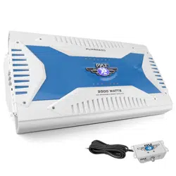
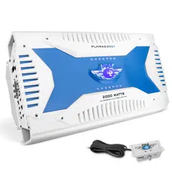
PLMRA220
High-Performance 600 Watt 2-Channel Bridgeable MOSFET Amplier
• 300 Watts x 2 Output
• 600 Watts x 1 Bridged Output
• Variable Hi/Lo Electronic Crossover Network
• Variable Bass Boost (0 to +18 dB @ 60Hz)
• Variable Input Level (Gain) Control
• Remote Turn On/O
• Gold-Plated RCA Inputs
• High-Level MOLEX Input
• Power ON LED Indicator
• LED Protection Indicator
• S/N Ratio: > 95 dB
• THD: < 0.04%
• Thermal Protection
• Overload Protection
• Short Circuit Protection
• Anti-Thump Turn-On
• Blue LED Level Display
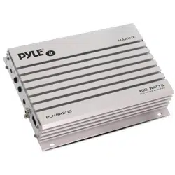
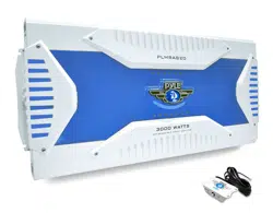
PLMRA420
High-Performance 1000 Watt 4-Channel Bridgeable MOSFET Amplier
• 250 Watts x 4 Output
• 500 Watts x 2 Bridged Output (250 Watts x 2 + 500 Watts x 1)
• Dual Variable Hi/Lo Electronic Crossover Network
• Dual Variable Bass Boost (0 to +18 dB @ 60Hz)
• Variable Input Level (Gain) Control
• Remote Turn On/O
• Gold-Plated RCA Inputs
• High-Level MOLEX Inputs
• Power ON LED Indicator
• LED Protection Indicator
• S/N Ratio: > 95 dB
• THD: < 0.04%
• Thermal Protection
• Overload Protection
• Short Circuit Protection
• Anti-Thump Turn-On
• Tri-Mode Congurable
• Blue LED Level Display
www.PyleUSA.com
5
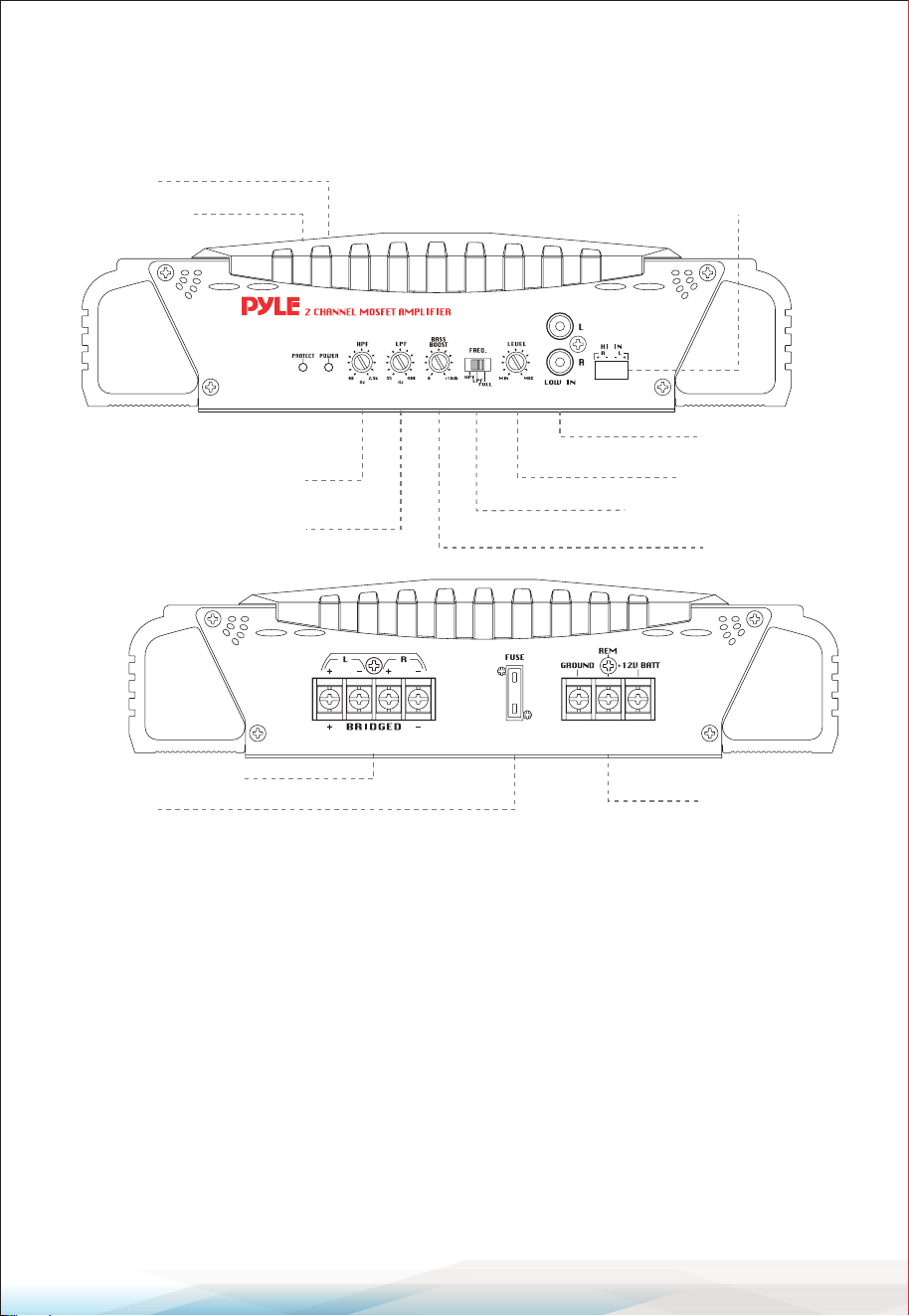
Features and Controls
PLMRA220 - 2 Channel Amplier
Control Functions
Crossover Mode Selector: When used with normal full-range systems, set this
switch to "FULL." If you wish to use the internal crossover to power a driver of a
specic frequency range, use the "LOWPASS" or "HIGHPASS" settings.
Input Level Control: Use this control to match the output of your head unit to
the amplier. Start with your head unit set at about the 2 o'clock position,
increase the amp level control until distortion begins, and then reduce slightly.
Low Pass Frequency Control: When the crossover selector switch is in "LOW
PASS" mode, this control sets the upper frequency limit for the audio program
sent to the speakers.
Speaker Connections
Power Fuse
Power Terminals
Power LED
Protection LED
High-Level Inputs
Low-Level Inputs
Input Level Control
Crossover Mode Selector
Bass Boost Level
High Pass Frequency Control
Low Pass Frequency Control

www.PyleUSA.com
6
High Pass Frequency Control: When the crossover selector switch is in "HIGH-
PASS" mode, this control sets the lower frequency limit for the audio program
sent to the speakers.
Bass Boost Level Control: This control permits adjustment of the bass level up
to an increase of approximately 18 dB.
Low-Level Inputs: This amp features gold-plated RCA input jacks for high
impedance input. Use these with car stereo outputs that utilize RCA-type
connector cables.
High-Level Inputs: If your car stereo lacks RCA-type output jacks, you may
connect the speaker output leads to these input connectors.
Power LED: This indicator lights up when power is applied.
Protection LED: This indicator lights up when the built-in protection circuitry is
activated.
Power Fuse: The fuse protects the amplier and your car's electrical system
from short circuits.
Power Terminals: Use these connectors to deliver power, ground, and remote
turn-on control to the amplier.
Speaker Connections: These terminals are 14K gold-plated to guarantee high
conductivity and minimize signal loss.
Technical Specications
Output Power @ 14.4V DC, 1KHz:
• RMS Power @ 4 Ohms: 40 Watts x 2
• RMS Power @ 2 Ohms: 70 Watts x 2
• Maximum Power Output: 300 Watts x 2
Frequency Response: 15 Hz - 30 KHz
Input Impedance:
• Low-Level Inputs: 10K Ohms
• High-Level Inputs: 100 Ohms
www.PyleUSA.com
7
Input Sensitivity:
• Low-Level Inputs: 250mV
• High-Level Inputs: 2.5V
Power Supply Voltage: 14.4V DC Negative Ground (10.5-16V)
Matching Speaker Impedance:
• Stereo Mode: 2-4 Ohms
• Bridged Mode: 4-8 Ohms
Maximum Current Draw: 15A
Dimensions (W x H x D): Inches: 10.9 x 2.7 x 8.25
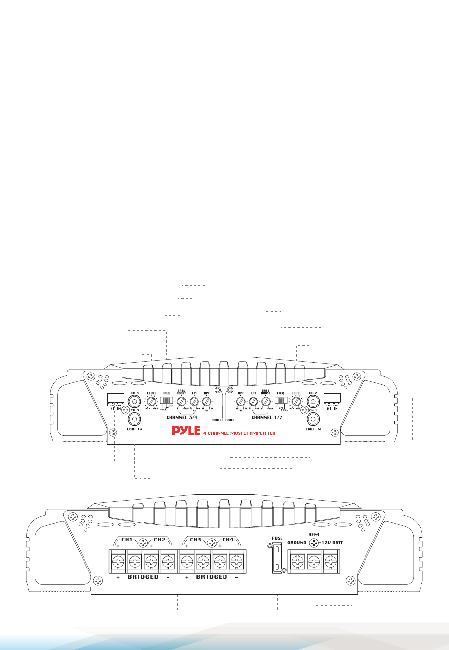
Features and Controls
PLMRA420 - 4 Channel Amplier
Control Functions
Speaker Connections Power Fuse
Power Terminals
CH 3/4 High Pass Frequency Control
CH 3/4 Low Pass Frequency Control
CH 3/4 Bass Boost Level Control
CH 3/4 Crossover Mode
Selector Switch
CH 3/4 Input Level Control
CH 3/4
High-Level
Inputs
CH 3/4 Low-Level Inputs
Protection LED
Power LED
CH 1/2
High-Level
Inputs
CH 1/2 High Pass Frequency Control
CH 1/2 Low Pass Frequency Control
CH 1/2 Bass Boost Level Control
CH 1/2 Crossover Mode
Selector Switch
CH 1/2 Input Level Control
CH 1/2 Low-Level Inputs

www.PyleUSA.com
8
Crossover Mode Selector: When used with normal, full-range systems, set this
switch to “FULL.” For specic frequency range drivers, use the “LOWPASS” or
“HIGHPASS” settings.
Input Level Control: Match the outputs of your head unit to the amplier.
Start with the head unit at about the 2 o’clock position, then adjust the amp
level control until distortion begins, and reduce slightly.
Low Pass Frequency Control: When the crossover selector switch is in
“LOWPASS” mode, this control sets the upper frequency limit for audio sent
to the speakers.
High Pass Frequency Control: When the crossover selector switch is in
“HIGHPASS” mode, this control sets the lower frequency limit for audio sent
to the speakers.
Bass Boost Level Control: Adjusts the bass level up to an increase of a
pproximately 18 dB.
Inputs and Outputs
• Low-Level Inputs: Gold-plated RCA input jacks for high impedance input,
ideal for car stereos with RCA-type connector cables.
• High-Level Inputs: Connect speaker output leads if your car stereo lacks
RCA-type output jacks.
Indicators and Protection
• Power LED: Illuminates when power is applied.
• Protection LED: Illuminates when built-in protection circuitry is activated.
• Power Fuse: Protects the amplier and your car’s electrical system from short
circuit conditions.
Technical Specications
Output Power @ 14.4V DC, 1KHz:
• RMS Power @ 4 Ohms: 35 Watts x 4
• RMS Power @ 2 Ohms: 50 Watts x 4
• Maximum Power Output: 250 Watts x 4
Frequency Response: 15 Hz - 30 KHz
www.PyleUSA.com
9
Input Impedance:
• Low-Level Inputs: 10K Ohms
• High-Level Inputs: 100 Ohms
Input Sensitivity:
• Low-Level Inputs: 250mV
• High-Level Inputs: 2.5V
Power Supply Voltage: 14.4V DC Negative Ground (10.5 - 16V)
Matching Speaker Impedance:
• Stereo Mode: 2-4 Ohms
• Bridged Mode: 4-8 Ohms
• Maximum Current Draw: 20A
• Dimensions (W x H x L): 10.9 x 2.7 x 12 inches
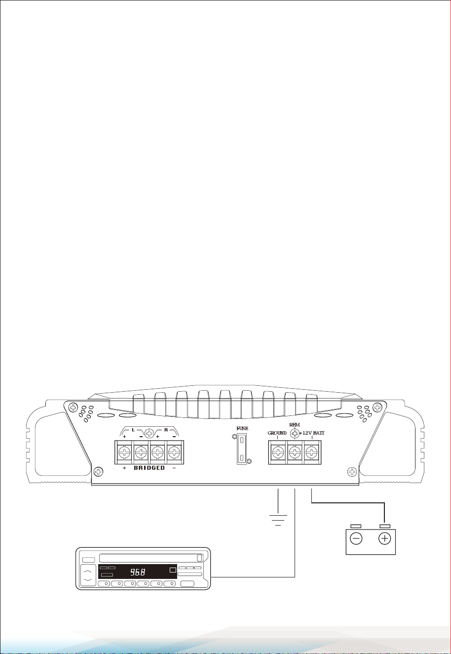
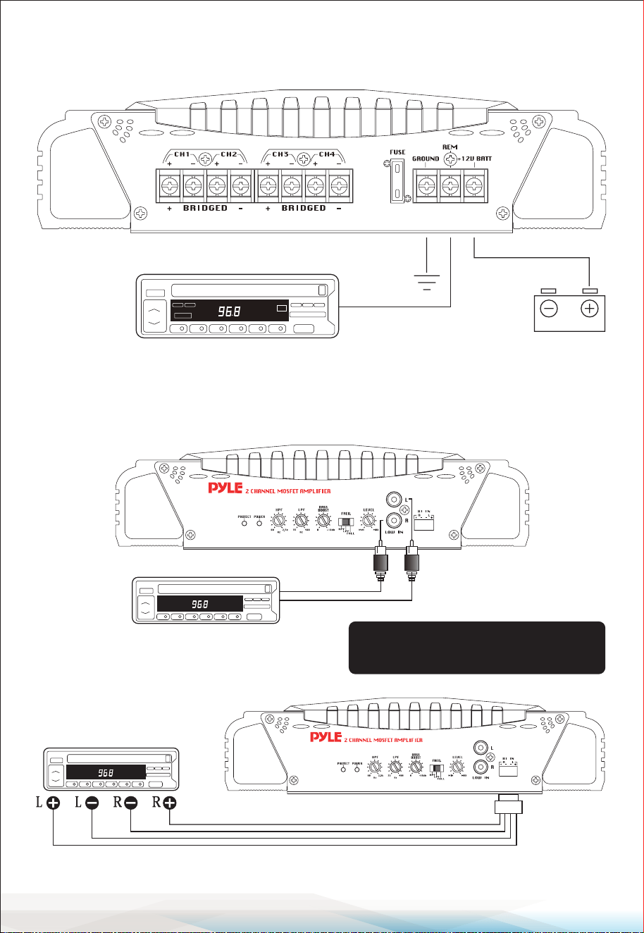
Electrical Connections
PLMRA220
Head Unit
Turn ON remote
+12V
12V battery
www.PyleUSA.com
10
Electrical Connections
PLMRA420
Stereo Input Connections
PLMRA220
Using Low Level Inputs
Using High-Level Inputs
Head Unit
Turn ON remote
+12V
12V battery
Head Unit
L/R Audio Outputs
from speaker terminals Wiring harness
Head Unit
PLEASE NOTE:
If using high-level inputs, do not use the
low-level RCA inputs at the same time.
www.PyleUSA.com
11
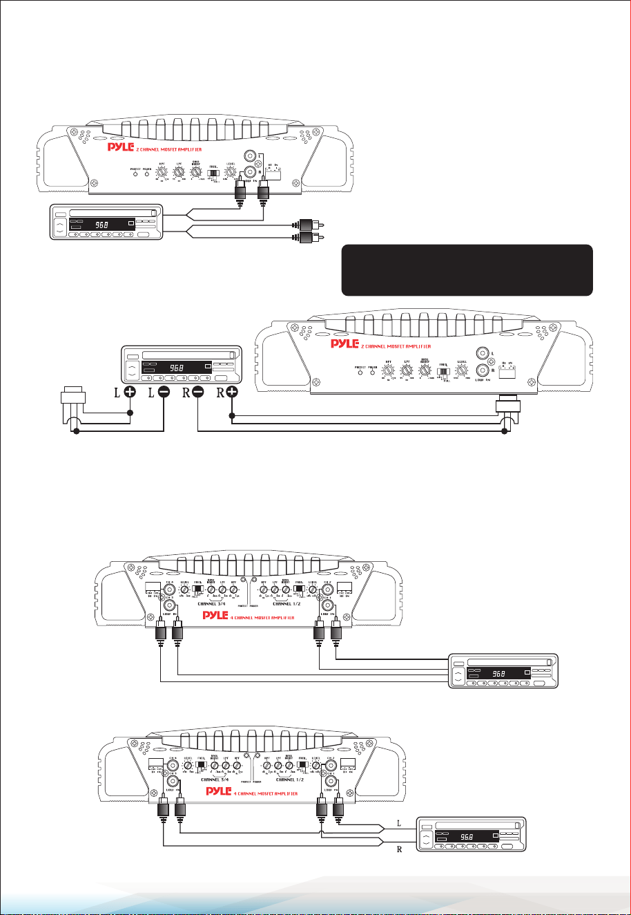
Mono Input Connections
PLMRA220
Using Low Level Inputs
Using High-Level Inputs
2/4 Channel Input Connections
PLMRA420
4 CH Input Connections Using Low-Level Inputs
2 CH Input Connections Using Low-Level Inputs
from speaker terminals Wiring harness
Head Unit
To a Second
Amplier
Y Adaptors
To a Second Amplier
Head Unit
PLEASE NOTE:
If using high-level inputs, do not use the
low-level RCA inputs at the same time.
Head Unit
L/R Front
Audio Outputs
L/R Rear
Audio Outputs
Y Adaptors
www.PyleUSA.com
12
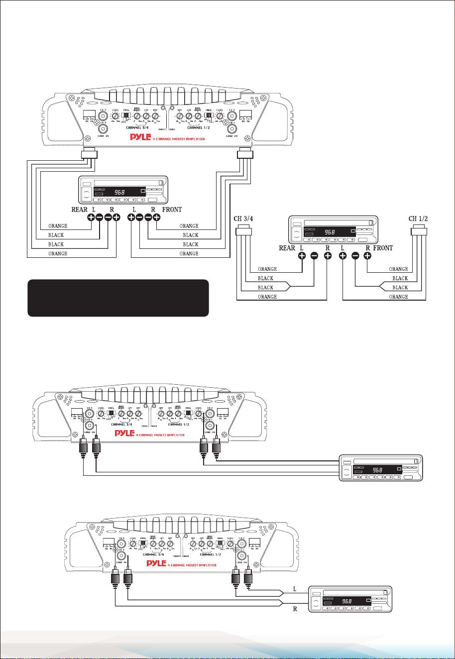
High Level Input Connections
PLMRA420
4 CH Floating Ground Connections
Mono Input Connections
PLMRA420
4 CH Mono Input Connections Using Low-Level Inputs
2 CH Input Connections Using Low-Level Inputs
PLEASE NOTE:
If using high-level inputs, do not use the
low-level RCA inputs at the same time.
from speaker terminals
from speaker terminals
4 CH Harness Wiring for
Common Ground Connections
Head Unit
Right Front
Audio Outputs
Right Rear Audio Outputs
Left Front Audio Outputs
Left Rear Audio Outputs
Y Adaptors
www.PyleUSA.com
13
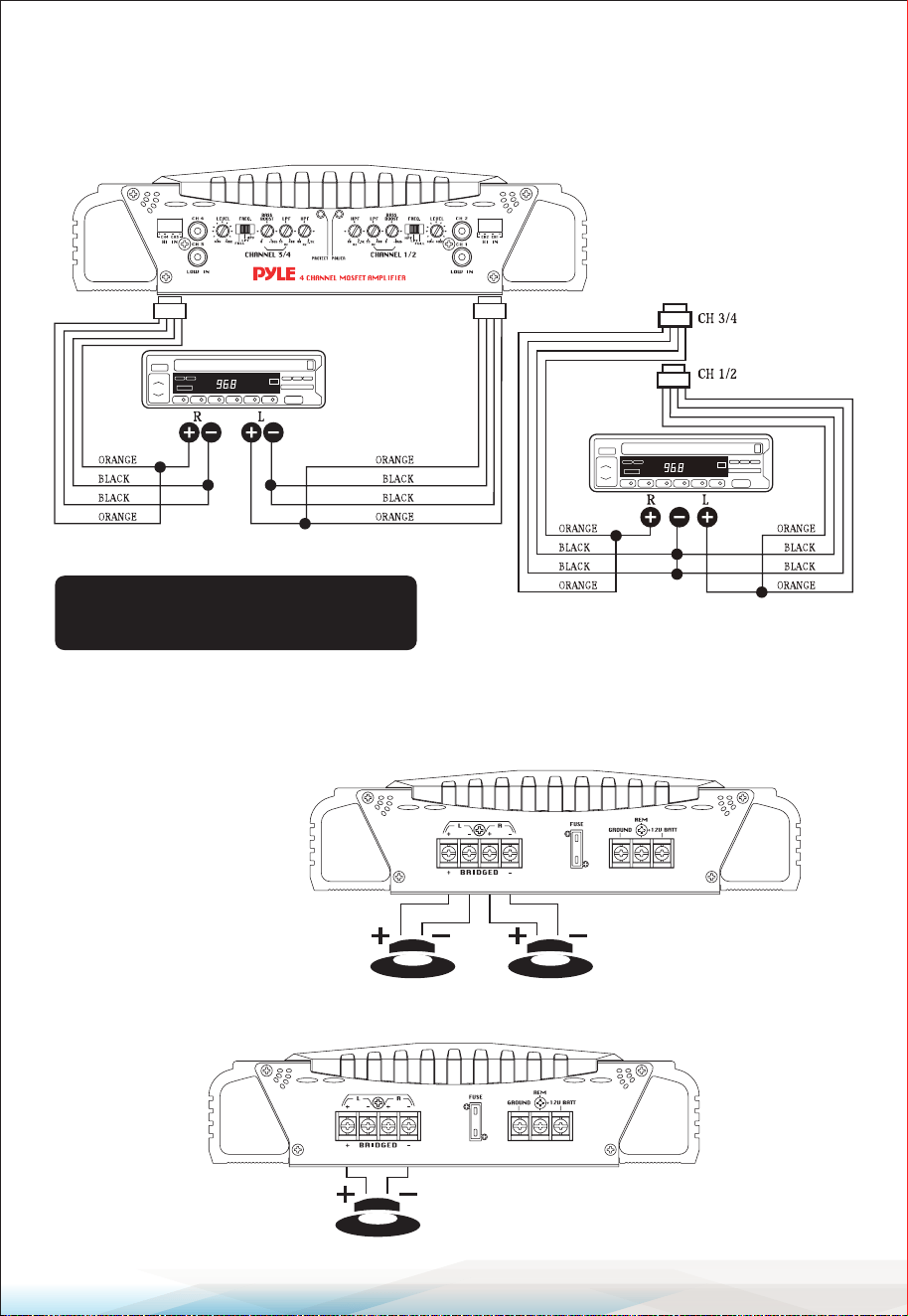
High Level Mono Input Connections
PLMRA420
4 CH Floating Ground Connections
Speaker Connections
PLMRA220
Stereo Output Mode
Bridged Mono Output Mode
PLEASE NOTE:
If using high-level inputs, do not use the
low-level RCA inputs at the same time.
from speaker terminals
4 CH Harness Wiring for
Common Ground Connections
from speaker terminals
Minimum Speaker
Impedance: 4 Ohms
Left Speaker Right Speaker
Speaker
www.PyleUSA.com
14
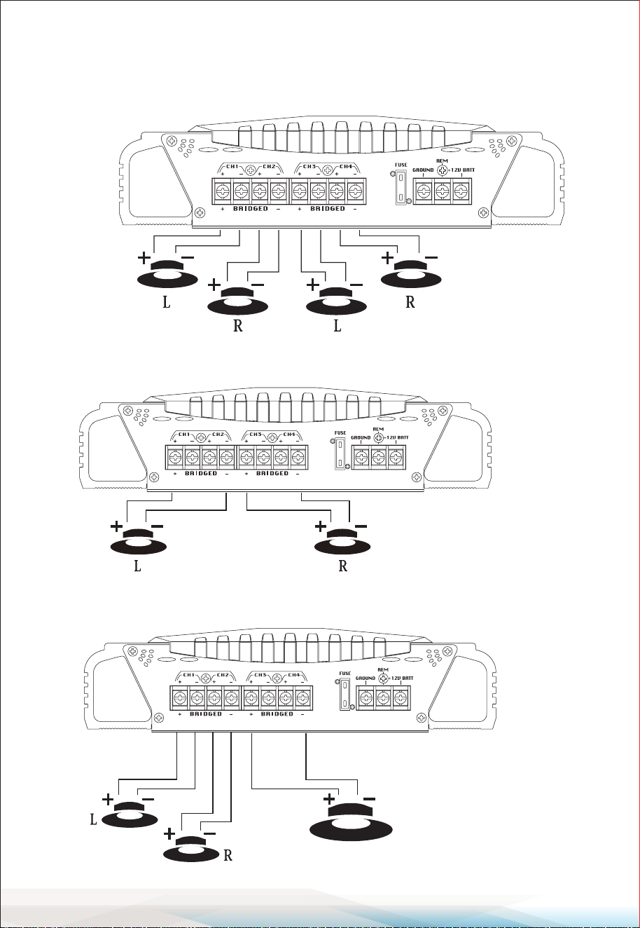
Speaker Connections
PLMRA420
4 CH Output Mode
Bridged Dual Mono Output Mode
4 CH Stereo Output Mode with Mono Bridged Subwoofer Output
Front Speaker Rear Speaker
Minimum Speaker
Impedance: 4 Ohms
Speakers
Minimum Speaker
Impedance: 4 Ohms
Speakers
Subwoofer

www.PyleUSA.com
15
Mounting and Installation
Mounting
Your new Pyle Marine Series amplier comes with all necessary mounting
hardware. When choosing a location in your vehicle, keep in mind that the
amplier is a high-power electronic device that generates signicant heat.
Key Considerations for Mounting
• Choose a location with low vibration, adequate ventilation, minimal dust, and
no moisture.
• Ensure there is sucient airow around the cooling ns.
Steps for Mounting
1. Position the Amplier: Place the amplier where you want to install it.
2. Mark Screw Holes: Use a scribe or one of the mounting screws to mark the
mounting surface through the screw holes. If the surface is carpeted,
measure the hole centers and mark them with a felt-tip pen.
3. Check for Obstructions: Before drilling, check for any wires, lines, or other
components behind the mounting surface.
4. Drill Pilot Holes: Drill the pilot holes in the marked locations.
5. Secure the Amplier: Insert and tighten the mounting screws securely.
Wiring Tips
When connecting your amplier, follow these guidelines:
• Power and Ground Connections: Use at least 8 gauge wire.
• Direct Connection: Wire the amplier directly to the car battery.
• Grounding: Use the shortest possible wire to connect to a good chassis
ground point.
• Remote Connection: Wire the Remote connection to the auto start lead of
your head unit, equalizer, or power antenna.
About Power Fuses
Pyle Marine Series ampliers have a built-in fuse system to protect both the
amplier and your vehicle's electrical system from faults.
Fuse Replacement: If you need to replace a fuse, use one with the exact same
type and rating. Using a dierent type or rating could cause damage or a re.

www.PyleUSA.com
16
Precautions
Mounting: Do not operate the amplier when it is unmounted. Securely attach
all audio system components within the vehicle to prevent damage, especially
in case of an accident.
Wiring Protection: Ensure the wire connections are protected, not pinched,
and not likely to be damaged by nearby objects.
Battery Disconnection: Before making or breaking power connections,
disconnect the vehicle battery. Make sure your head unit or other equipment is
turned o while connecting the input jacks and speaker terminals.
Fuse Replacement: If you need to replace the power fuse, only use a fuse
identical to the one supplied with the amplier. Using a dierent type or rating
may result in damage that isn’t covered under the manufacturer's warranty.
Protection Circuitry
The built-in protection circuitry in the Marine ampliers will disable the
amplier if it detects:
• Input overload
• Speaker short circuit
• Extreme temperature conditions
Protection LED:
When the protection circuit is activated, the Protection LED will illuminate.
Steps to Follow:
• Thermal Overload: If the shutdown is due to thermal overload, allow the
amplier to cool down before restarting.
• Input Overload/Speaker Short Circuit: If the shutdown is due to input
overload or a speaker short circuit, correct the issue before restarting.
• Restarting: Turn the remote power OFF and then ON again to restart the
amplier.

www.PyleUSA.com
17
Troubleshooting
No Output:
• Ensure all terminal strip connections are secure and tight.
• Check both in-line and built-in fuses. Both the +12V and the Remote terminals
must have +12V referenced to the chassis ground.
• Verify that the audio signal source (car radio, equalizer, etc.) is connected and
supplying an output signal.
• To check if the amp is supplying a signal, unplug the cables from the signal
source (but leave them plugged into the amp). Briey tap the center pin of
each disconnected RCA plug with your nger. This should produce a noise
(feedback) in your speakers.
Only One Channel Works:
• Ensure all terminal strip connections are secure and tight.
• Check the Balance control on the head unit (or other source) to ensure it is set
to the midpoint.
• If using the Low-Level RCA input, reverse the input plugs at the amplier
(i.e., switch the L with the R). If the silent channel switches to the other side,
the problem is either in the head unit/other source or the connecting cables.
Weak Output: Adjust the Input Level Control(s) to better match the input signal.
Noise in the Audio:
• Whine (Engine Speed-Dependent): Ensure that the amplier and any other
signal sources (head unit, etc.) are properly grounded.
• Clicking/Popping (Engine Speed-Dependent): This usually indicates that the
vehicle has resistor spark plugs and wires, or the ignition needs servicing.
• Check Wiring: Ensure that the speaker and input wires are not near wires that
interconnect lights and other accessories.
• If these steps don't resolve the noise interference, consult a professional
mobile audio installer.

www.PyleUSA.com
18
FCC Caution
This device complies with part 15 of the FCC Rules. Operation is subject to the
following two conditions: (1) This device may not cause harmful interference,
and (2) this device must accept any interference received, including interference
that may cause undesired operation.
Any Changes or modications not expressly approved by the party responsible
for compliance could void the user's authority to operate the equipment.
Note:
This equipment has been tested and found to comply with the limits for a Class
B digital device, pursuant to part 15 of the FCC Rules. These limits are designed
to provide reasonable protection against harmful interference in a residential
installation. This equipment generates uses and can radiate radio frequency
energy and, if not installed and used in accordance with the instructions, may
cause harmful interference to radio communications. However, there is no
guarantee that interference will not occur in a particular installation.
If this equipment does cause harmful interference to radio or television
reception, which can be determined by turning the equipment o and on, the
user is encouraged to try to correct the interference by one or more of the
following measures:
• Reorient or relocate the receiving antenna.
• Increase the separation between the equipment and receiver.
• Connect the equipment into an outlet on a circuit dierent from that to which
the receiver is connected.
• Consult the dealer or an experienced radio/TV technician for help.
The device has been evaluated to meet general RF exposure requirement.
The device can be used in portable exposure condition without restriction.

www.PyleUSA.com
19
IC warning
- English:
This device complies with Industry Canada licence-exempt RSS standard(s).
Operation is subject to the following two conditions:
(1) This device may not cause interference, and (2) This device must accept any
interference, including interference that may cause undesired operation of the
device.
- French:
L’émetteur/récepteur exempt de licence contenu dans le présent appareil est
conforme aux CNR d’Innovation, Sciences et Développement économique
Canada applicables aux appareils radio exempts de licence.
L’exploitation est autorisée aux deux conditions suivantes:
(1) L’appareil ne doit pas produire de brouillage; (2)L’appareil doit accepter tout
brouillage radioélectrique subi, même si le brouillage est susceptible d’en
compromettre le fonctionnement.
This equipment complies with IC RSS-102 radiation exposure limits set forth for
an uncontrolled environment. This equipment should be installed and operated
with minimum distance 20cm between the radiator & your body.
Cet équipement est conforme aux limites d'exposition aux rayonnements IC
établies pour un environnement non contrôlé. Cet équipement doit être installé
et utilisé avec un minimum de 20cm de distance entre la source de rayonnement
et votre corps.
Register Product
Thank you for choosing PyleUSA. By registering your product,
you ensure that you receive the full benets of our exclusive
warranty and personalized customer support.
Complete the form to access expert support and to keep
your PyleUSA purchase in perfect condition.
PyleUSA.com/register

Questions or Comments?
We are here to help!
Phone: 1.718.535.1800
PyleUSA.com/ContactUs