
49-5000888 Rev. 5
AIR CONDITIONER
RV
OWNER’S MANUAL
Rooftop Units:
Standard Height
GRCS13XHH_
GRHS13XHH_
GRCS13XAH_
GRHS13XAH_
GRCS15XAH_
GRHS15XAH_
Low Profile
PLCS13XHH_
PLHS13XHH_
PLCS13XAH_
PLHS13XAH_
PLCS15XAH_
PLHS15XAH_
Indoor Assemblies:
RPRED_ _
RPREN_ _
RGRED_ _
RGREN_ _
RGRMN_ _
ENGLISH
GE is a trademark of the General Electric Company. Manufactured under trademark license.
49-5000888 Rev. 5 05-25
Write the model and serial numbers
here:
Model # _______________
Serial # _______________
You can find them on a label on the
air conditioner.
SAFETY INFORMATION .........3
INSTALLATION INSTRUCTIONS
Before You Begin ......................4
Tools You will Need. . . . . . . . . . . . . . . . . . .4
RGRMN_ _ Parts List ...................5
RGREN_ _ Parts List ...................6
RGRED_ _ Parts List ...................7
RPREN_ _ Parts List ....................8
RPRED_ _ Parts List ....................9
Roof Requirements ...................10
Roof Requirements and Prep ...........12
Electrical Requirements ...............12
Placing Unit on Roof ..................12
Installing Unit ........................14
Electrical Control Installation ...........15
USING THE AIR CONDITIONER
Controls .............................18
Air Direction. . . . . . . . . . . . . . . . . . ......19
Normal Operating Sounds .............19
CARE AND CLEANING
Indoor Panel ........................ 20
Air Filter. . . . . . . . . . . . . . . . . . ......... 20
Annual Maintenance .................. 20
TROUBLESHOOTING TIPS ......21
SCHEMATIC DIAGRAMS ........22
LIMITED WARRANTY ...........23
CONSUMER SUPPORT ......... 24

2 49-5000888 Rev.5
THANK YOU FOR MAKING GE APPLIANCES A PART OF YOUR RV
Whether you grew up with GE Appliances, or this is your first, we’re happy to have you in the family.
We take pride in the craftsmanship, innovation and design that goes into every GE Appliances
product, and we think you will too. Among other things, registration of your appliance ensures that we
can deliver important product information and warranty details when you need them.
Register your GE appliance now online. Helpful websites and phone numbers are available in the
Consumer Support section of this Owner’s Manual.
349-5000888 Rev. 5
SAFETY INFORMATION
IMPORTANT SAFETY INFORMATION
READ ALL INSTRUCTIONS BEFORE USING THE APPLIANCE
WARNING
For your safety, the information in this manual must be followed to minimize the risk of
fire, electric shock or personal injury.
Ŷ8VHWKLVDSSOLDQFHRQO\IRULWVLQWHQGHGSXUSRVHDV
described in this Owner’s Manual.
ŶThis air conditioner must be properly installed in
accordance with the Installation Instructions before it
is used.
ŶReplace immediately all electric service cords that
have become frayed or otherwise damaged.
ŶTurn the unit OFF and disconnect all power to the
vehicle before cleaning and servicing.
ŶTo avoid risk of injury or property damage, the air
conditioner should only be serviced by a qualified
servicer who holds a current valid certificate from
an industry-accredited assessment authority, which
authorizes their competence to handle refrigerants
safely in accordance with industry recognized
assessment specifications.
ŶFor your safety, do not store or use combustible
materials, gasoline or other flammable vapors or
liquids in the vicinity of this or any other appliance.
ŶAll air conditioners contain refrigerants, which
under federal law must be removed prior to product
disposal. If you are getting rid of an old product
with refrigerants, check with the company handling
disposal about what to do.
ŶThese R32 air conditioning systems require
contractors and technicians to use tools, equipment,
and safety standards approved for use with this
refrigerant. DO NOT use equipment certified for
other refrigerants only.
ŶThis appliance is not intended for use by persons
(including children) with reduced physical, sensory
or mental capabilities, or lack of experience and
knowledge, unless they have been given supervision
or instruction concerning use of the appliance by a
person responsible for their safety.
For appliance recycling information, please visit GEAppliances.com/recycling
READ AND SAVE THESE INSTRUCTIONS
Ŷ'RQRWXVHPHDQVWRDFFHOHUDWHWKHGHIURVWLQJSURFHVV
or to clean, other than those recommended by the
manufacturer.
ŶThe appliance shall be stored in a room without
continuously operating ignition sources (for example:
open flames, an operating gas appliance or an
operating electric heater.
ŶDo not pierce or burn refrigerant tubing. Be aware that
refrigerants may not contain an odor.
ŶKeep ventilation openings clear of obstruction.
ŶWhen handling, installing, and operating the appliance,
care should be taken to avoid damage to the
refrigerant tubing.
ŶDo not drill holes in the unit.
ŶMaintenance, cleaning, and service should only be
performed by technicians properly trained and qualified
in the use of flammable refrigerants.
ŶGEAppliances does not support any servicing of
sealed system components (i.e. refrigerant containing
parts) in the air conditioner.
ŶDispose of air conditioner in accordance with Federal
and Local Regulations. Flammable refrigerants require
special disposal procedures. Contact your local
authorities for the environmentally safe disposal of your
air conditioner.
WARNING
Risk of Fire or Explosion. This unit contains flammable refrigerant.
Additional safety precautions must be followed.
A2L
4 49-5000888 Rev.5
General Knowledge
BEFORE YOU BEGIN
Read these instructions completely and carefully.
• Save these instructions for local inspector’s use.
• Observe all governing codes and ordinances.
• Note to Installer – Be sure to leave these
instructions with the Consumer.
• Note to Consumer – Keep these instructions for
future reference.
• Skill level – Installation of this appliance requires a
qualified RV technician.
• Completion time
– Approximately 1 hour
• We recommend that two people install this product.
• Proper installation is the responsibility of the installer.
• Product failure due to improper installation is not
covered under the Warranty.
<RX0867XVHDOOVXSSOLHGSDUWVDQGXVHSURSHU
installation procedures as described in these
instructions when installing this air conditioner.
Questions? Call 1-877-540-7837 or Visit our Website at: GEAppliances.com
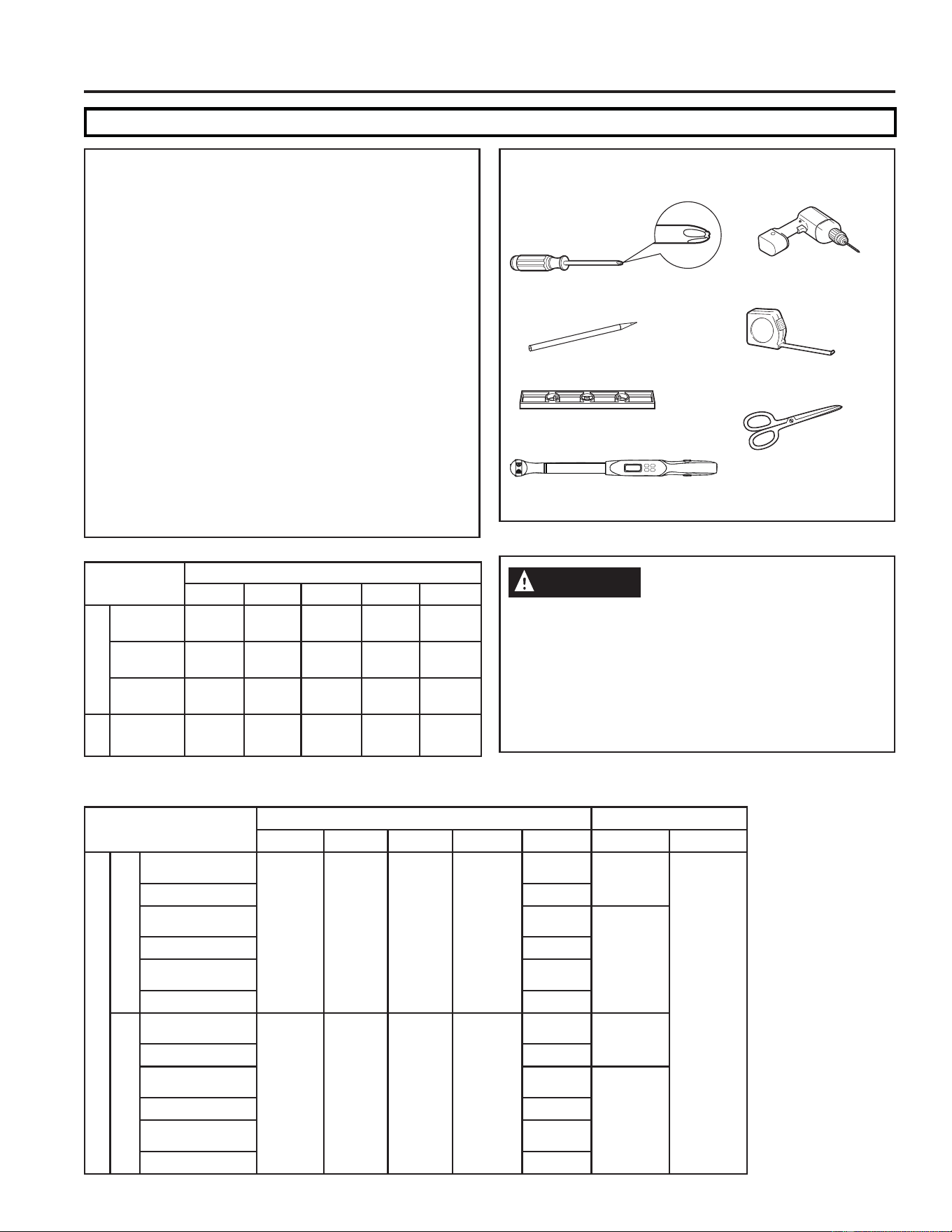
TOOLS YOU WILL NEED
Phillips head screwdriver
Ruler or tape measure
Pencil
Level
Scissors or knife
Torque Wrench (0-60 in-lbs)
Drill and 1/8” drill bit
CAUTION
Be cautious of sharp edges as they may cause
injury. When lifting the air conditioner, use 2
people to lift.
Electrical wiring may be present between roof
and ceiling. Be sure that power is disconnected
at the mains and battery. Be sure that the gas
supply is shut off. Failure to do so may result in
injury or death.
Indoor Assemblies
RPRED RPREN RGRED RGREN RGRMN
Elec. Control
RGREC1A
X
RGREC2A
X
RGREC3A
X
Tstat
RGRWT
X
Indoor Unit Breaker Size
RPRED RPREN RGRED RGREN RGRMN MCA MOP
Outdoor Unit
Standard Height
GRCS13XHH_
15A
20A
GRHS13XHH_
X
GRCS13XAH_
20A
GRHS13XAH_
X
GRCS15XAH_
GRHS15XAH_
X
Low Profile
PLCS13XHH_
15A
PLHS13XHH_
X
PLCS13XAH_
20A
PLHS13XAH_
X
PLCS15XAH_
PLHS15XAH_
X
INSTALLATION GUIDE
549-5000888 Rev. 5
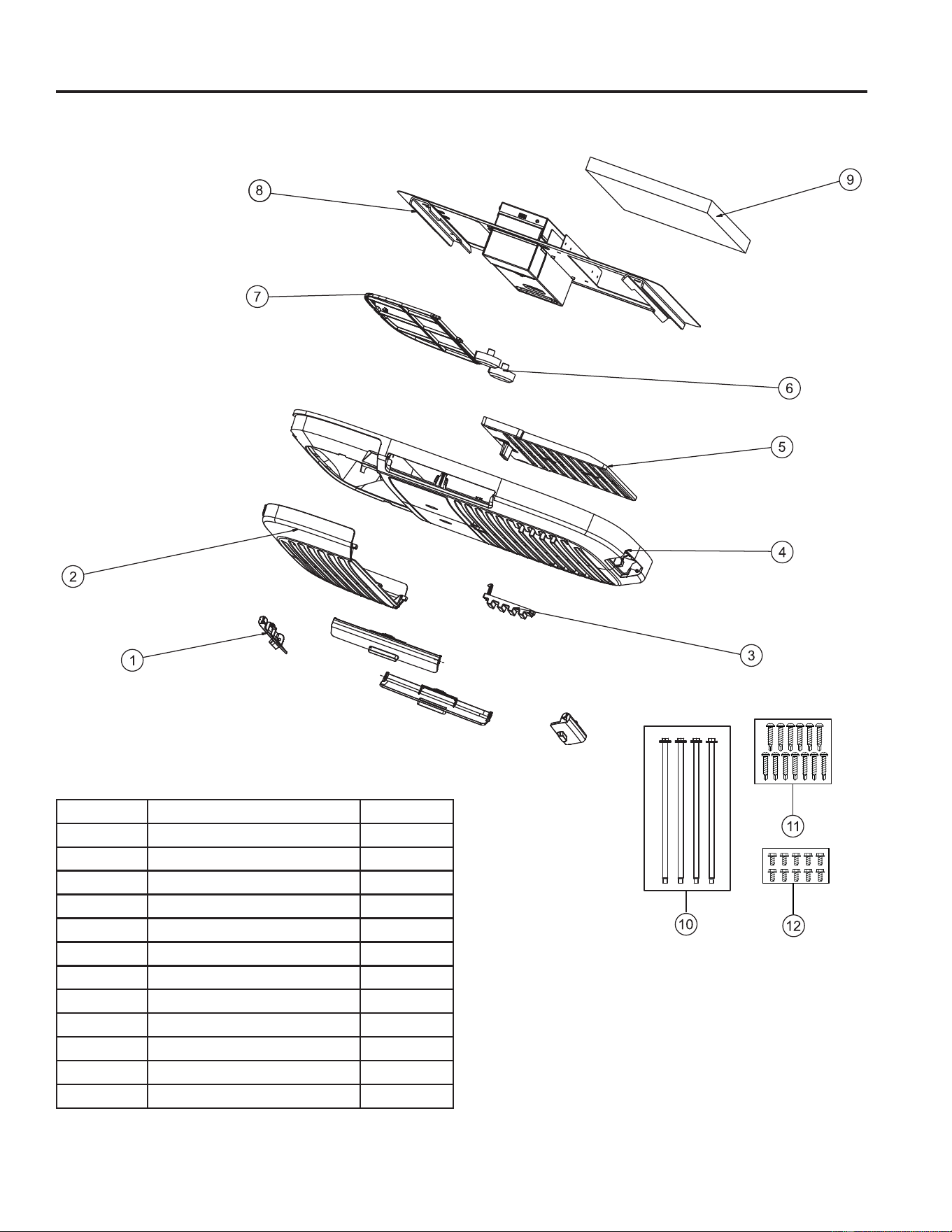
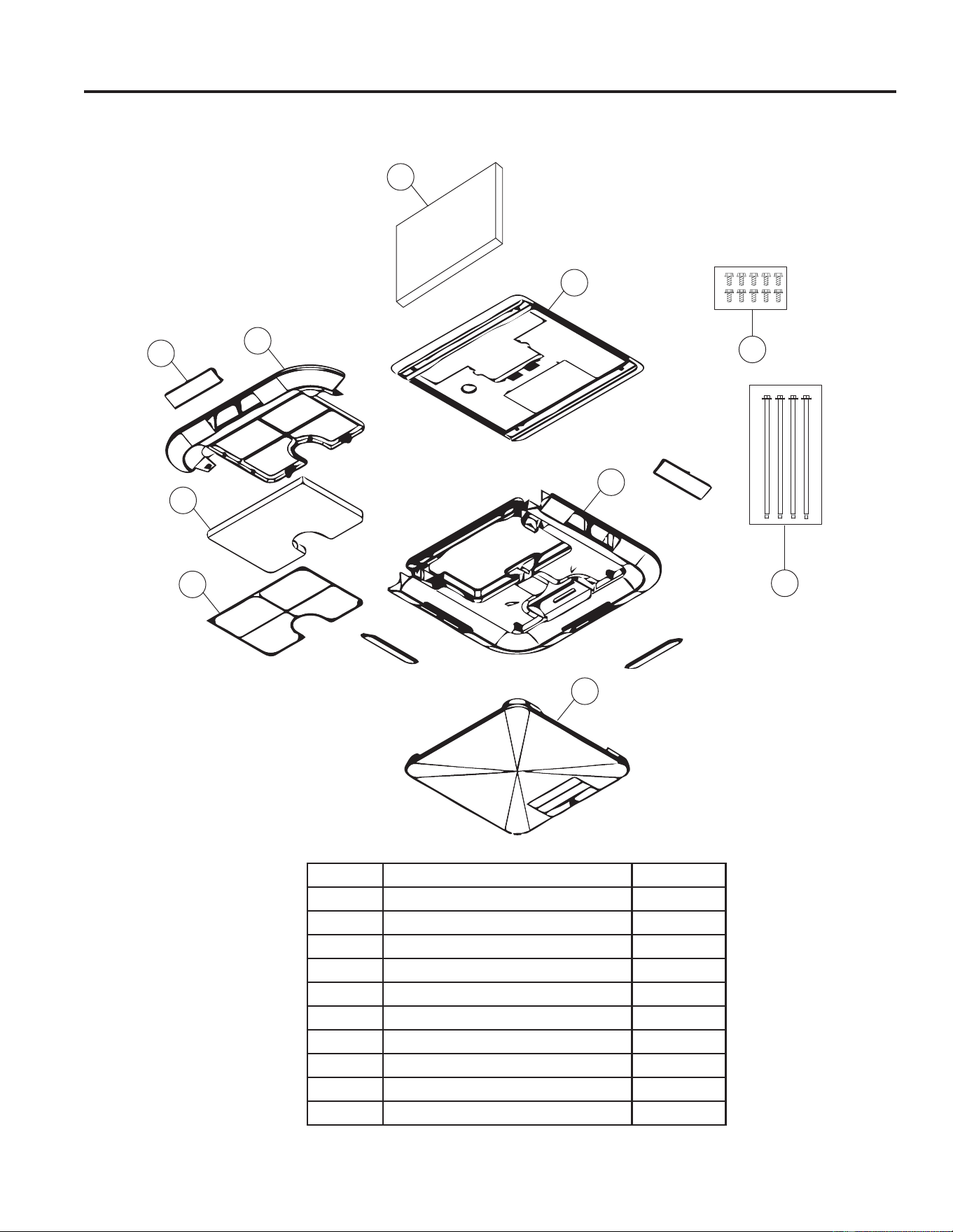
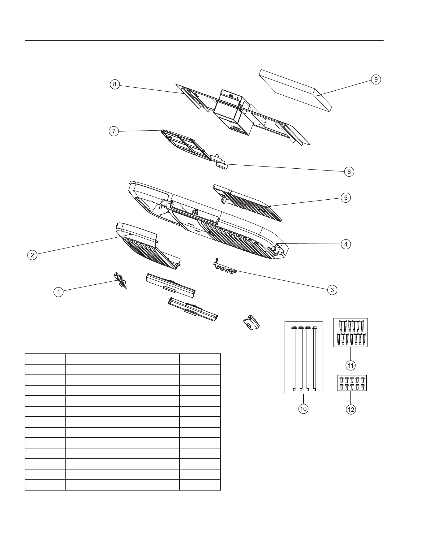
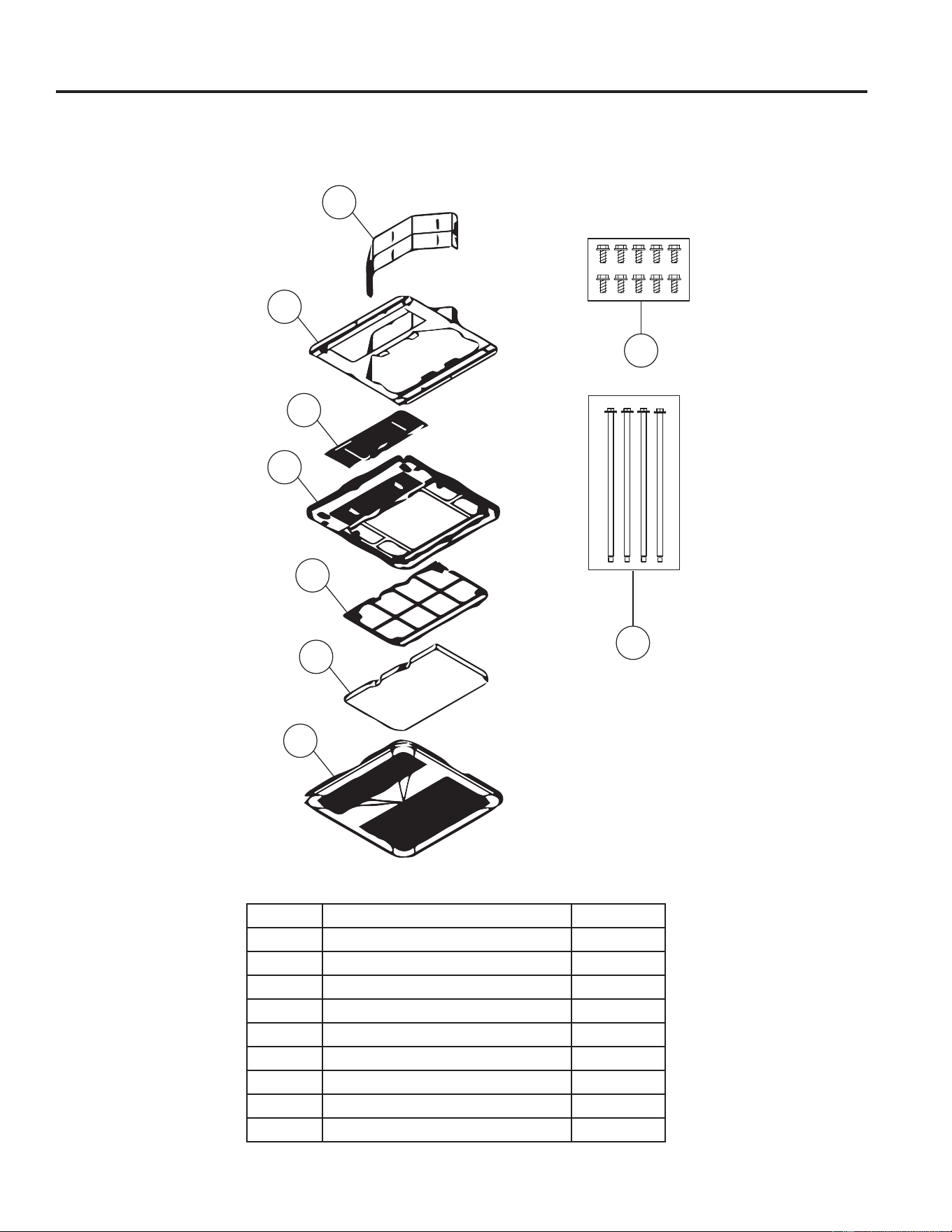
Exploded View
RGRMN
8
INSTALLATION GUIDE
Number Part Name Quantity
1 Air Discharge Louver 4
2 Filter Cover 1
3 Screw Cover 2
4 Ceiling Panel 1
5 Direct Air Discharge Guide 1
6 Knob 2
7 Filter 1
8 Mounting Template 1
9 Air Division Baffle 1
10 M8 Mounting Bolts 4
11 Wood Screws 13
12 Sheet Metal Screws 10
6 49-5000888 Rev.5
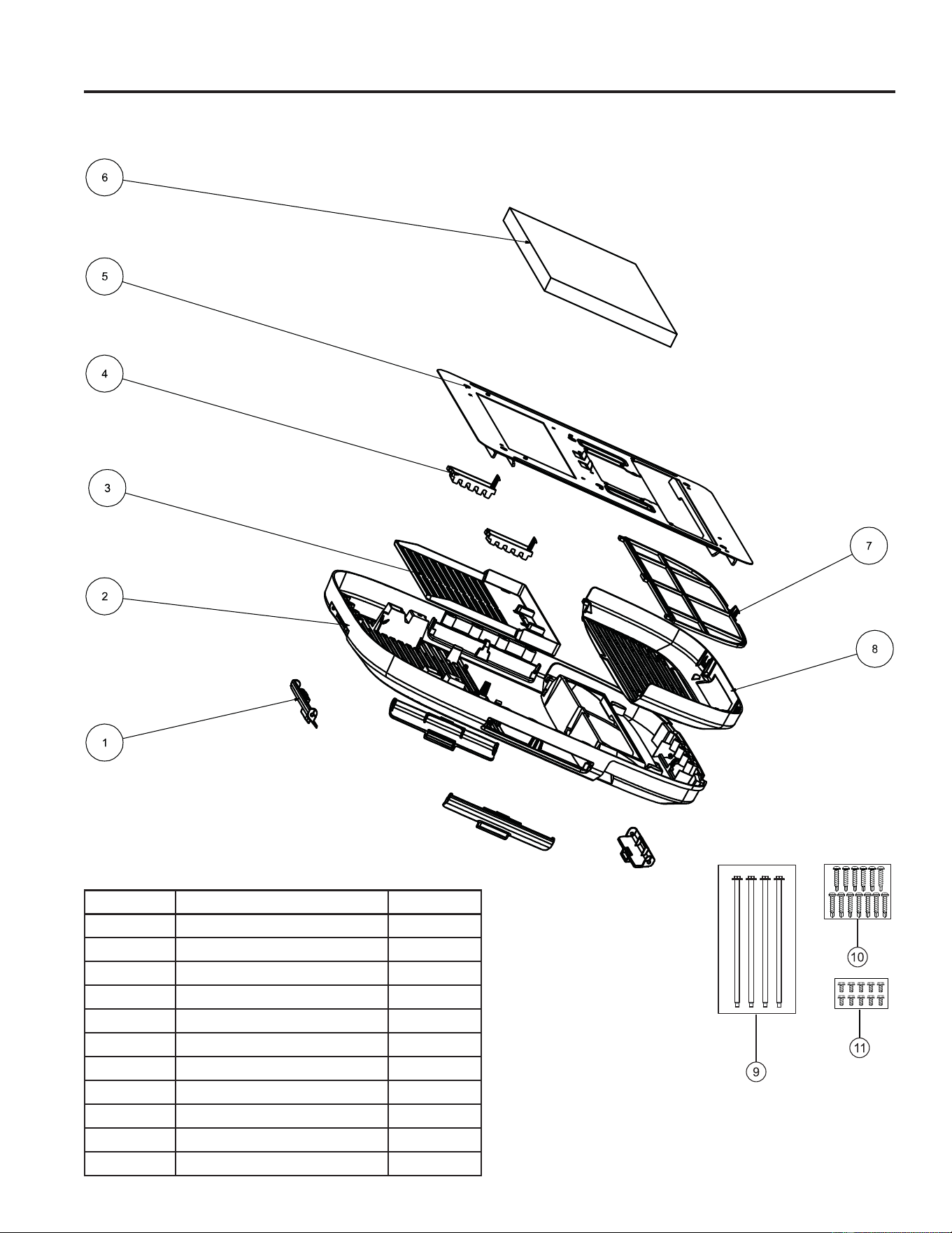
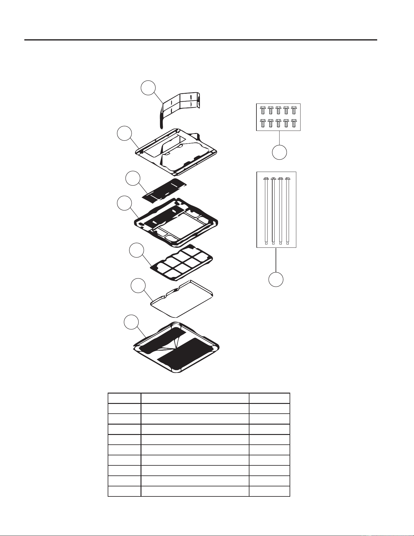
Exploded View
RGREN
INSTALLATION GUIDE
Number Part Name Quantity
1 Air Discharge Louver 4
2 Ceiling Panel 1
3 Filter Cover 1
4 Filter 1
5 Mounting Template 1
6 Air Division Baffle 1
7 Screw Covers 2
8 Direct Air Discharge Guide 1
9 M8 Mounting Bolts 4
10 Wood Screws 13
11 Sheet Metal Screws 10
749-5000888 Rev. 5
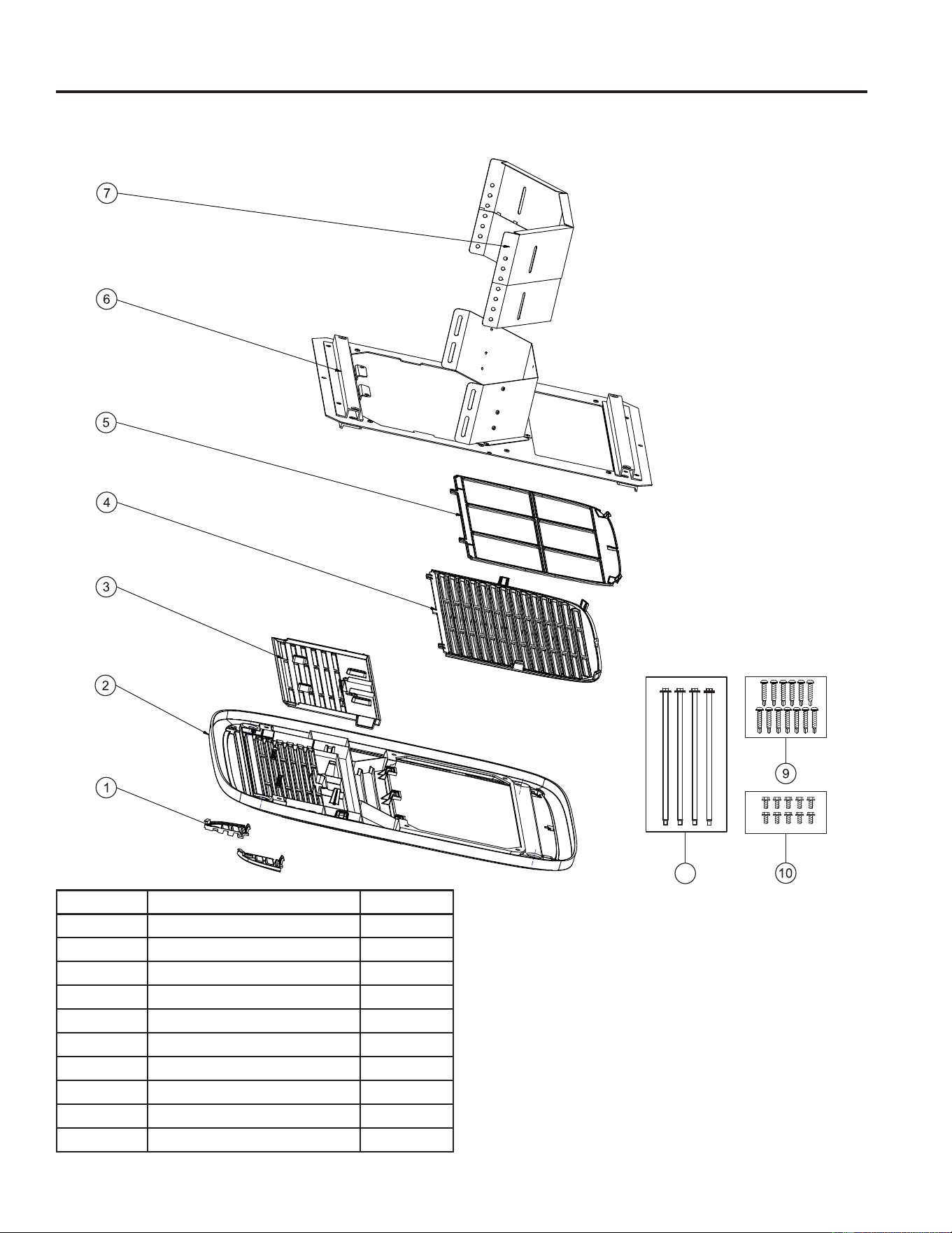
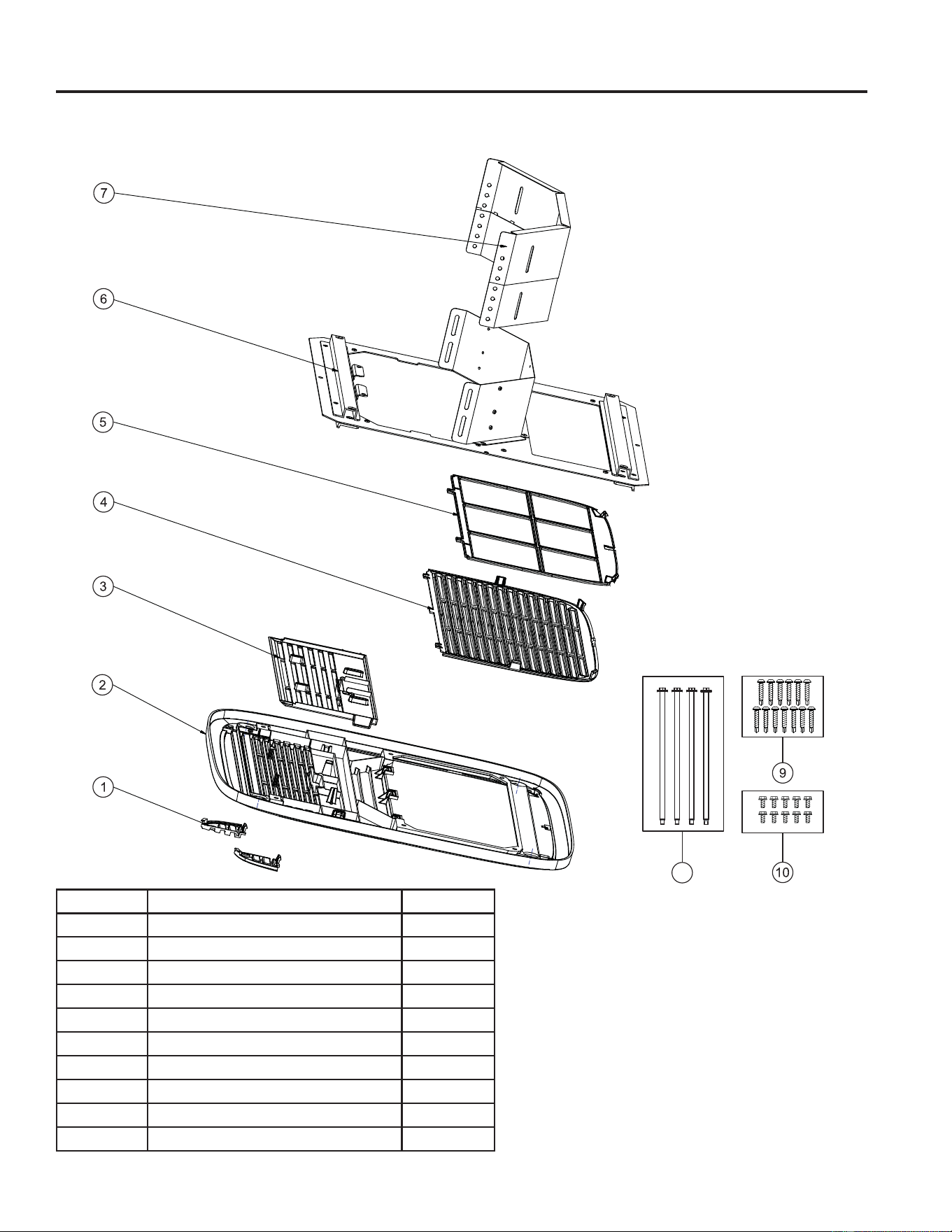
Exploded View
RGRED
INSTALLATION GUIDE
8
Number Part Name Quantity
1 Screw Covers 2
2 Ceiling Panel 1
3 Direct Air Discharge Guide 1
4 Filter Cover 1
5 Filter Retainer + Filter 1
6 Mounting Template 1
7 Air Division Baffle 1
8 M8 Mounting Bolts 4
9 Wood Screws 13
10 Sheet Metal Screws 10
8 49-5000888 Rev.5
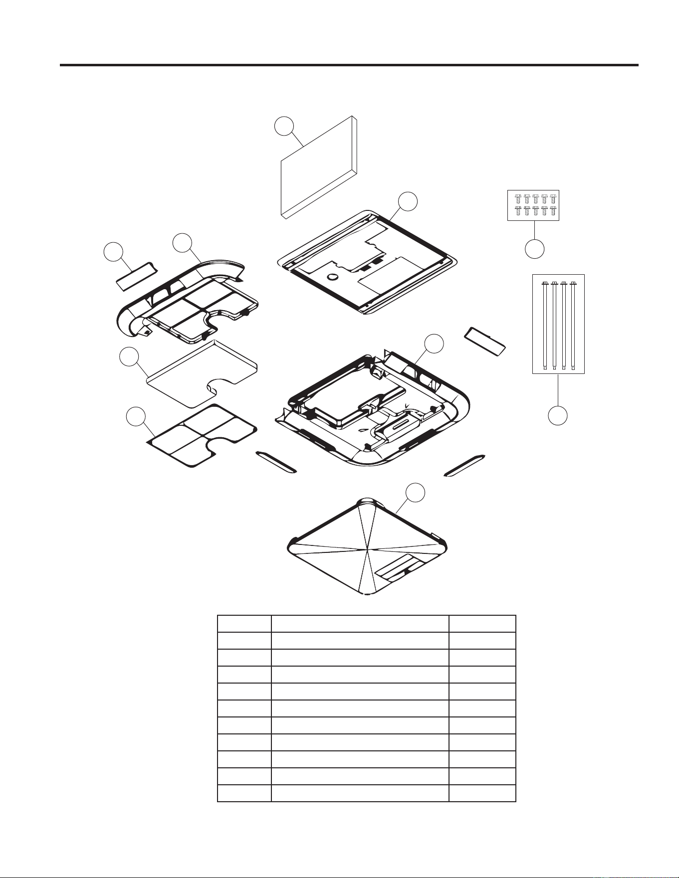
Exploded View
RPREN_ _- Electronic Non-Ducted
Check the contents of the accessories supplied with your air conditioner as shown below:
1
2
3
10
9
4
5
6
7
8
Number Part Name QTY.
1 Air Division Baffle 1
2 Mounting Template 1
3 Ceiling Panel Base 1
4 Ceiling Panel Cover 1
5 Filter Retainer 1
6 Filter 1
7 Filter Tray 1
8 Side Discharge Louver 4
9 M8 Mounting Bolts 4
10 Sheet Metal Screws 10
INSTALLATION GUIDE
949-5000888 Rev. 5
INSTALLATION GUIDE
RPRED_ _- Electronic Ducted
Check the contents of the accessories supplied with your air conditioner as shown below:
Exploded View
9
8
1
2
3
4
5
6
7
Number Part Name QTY.
1 Air Division Baffle 1
2 Mounting Template 1
3 Direct Discharge Guide 1
4 Ceiling Panel Base 1
5 Filter Retainer 1
6 Filter 1
7 Ceiling Panel Cover 1
8 M8 Mounting Bolts 4
9 Sheet Metal Screws 10
10 49-5000888 Rev.5
Figure 3: GE Appliances Indoor Non-Ducted Unit:
Installation Instructions
A. ROOF REQUIREMENTS AND DETERMINING LOCATION FOR INSTALLATION
• Air conditioners covered in this manual are designed for
installation on an RV’s roof.
• Installation of this air conditioner must be in accordance with
NFPA 1192 and NFPA 70.
• For proper installation, there must be a 14ñ»”x14ñ»” (+/-ï»”)
square opening in the roof and ceiling of the RV.
• There must be 2-6” of space between the RV ceiling and the
roof to accommodate our air division baffle.
• Air conditioners covered in this manual are designed to fit
over preexisting roof vent openings.
• If a roof vent opening isn’t available, use the following
guidelines:
8QLWLVWREHLQVWDOOHGFHQWHUHGVLGHWRVLGHRQWKH59URRI
8QLWLVWREHLQVWDOOHGRQDVHFWLRQRIURRIZKLFKLVOHYHOZLWK
respect to the RV roof if parked on a flat, level surface.
• Roof at the point of install can have a maximum tilt angle of
15° toward the front or rear of the RV.
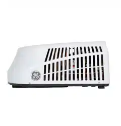
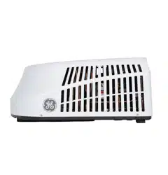
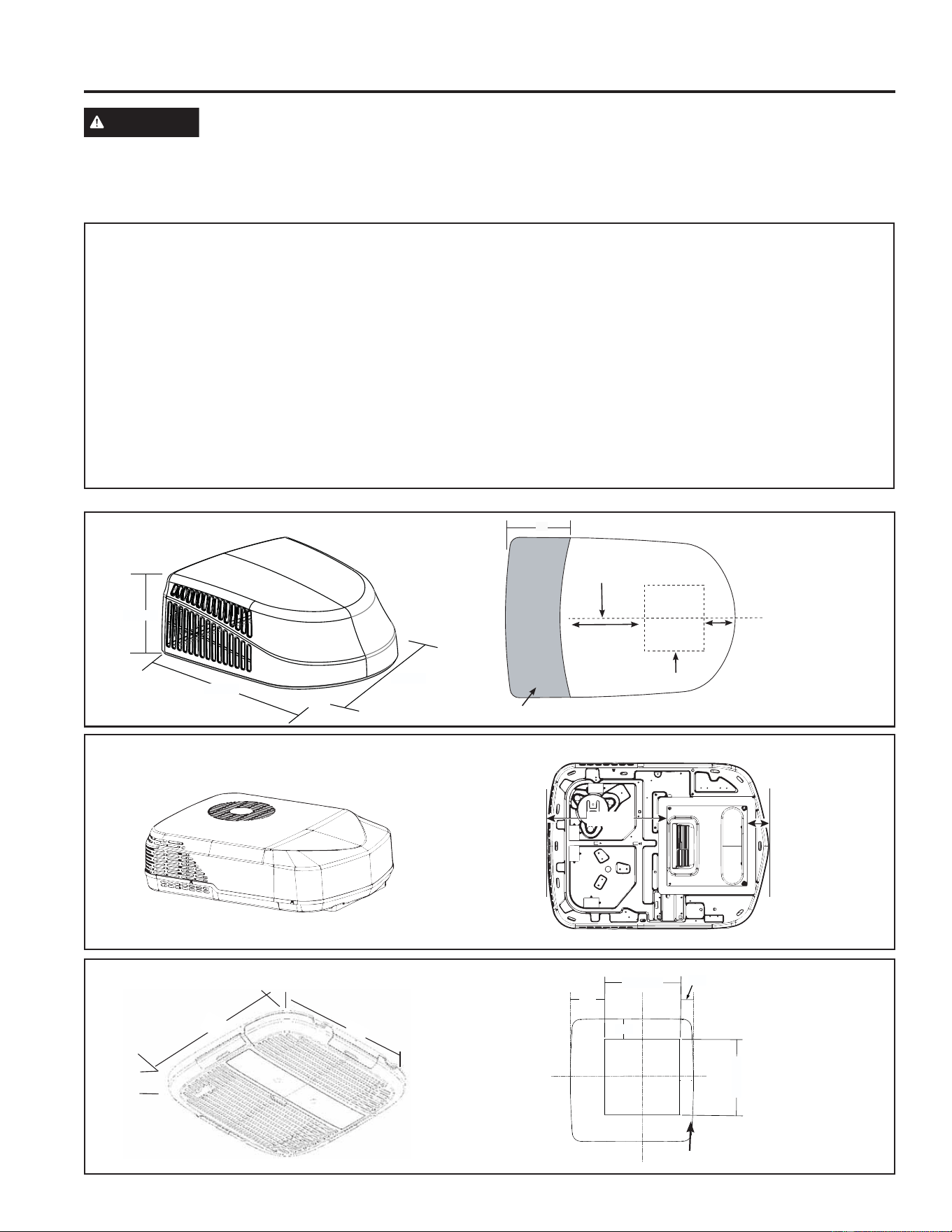
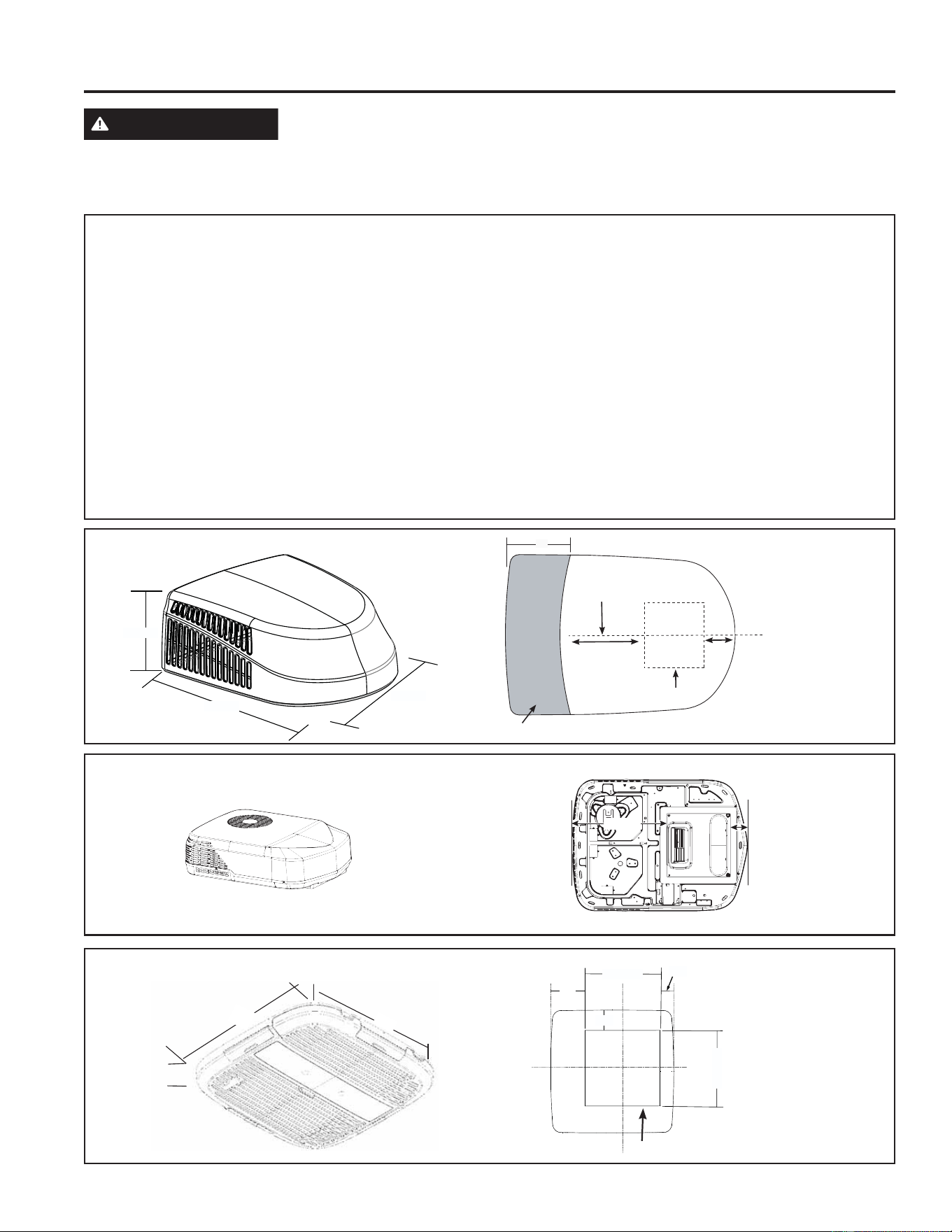
Figure 1: GE Appliances Outdoor Unit
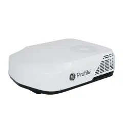
Figure 2: GE Profile Outdoor Unit
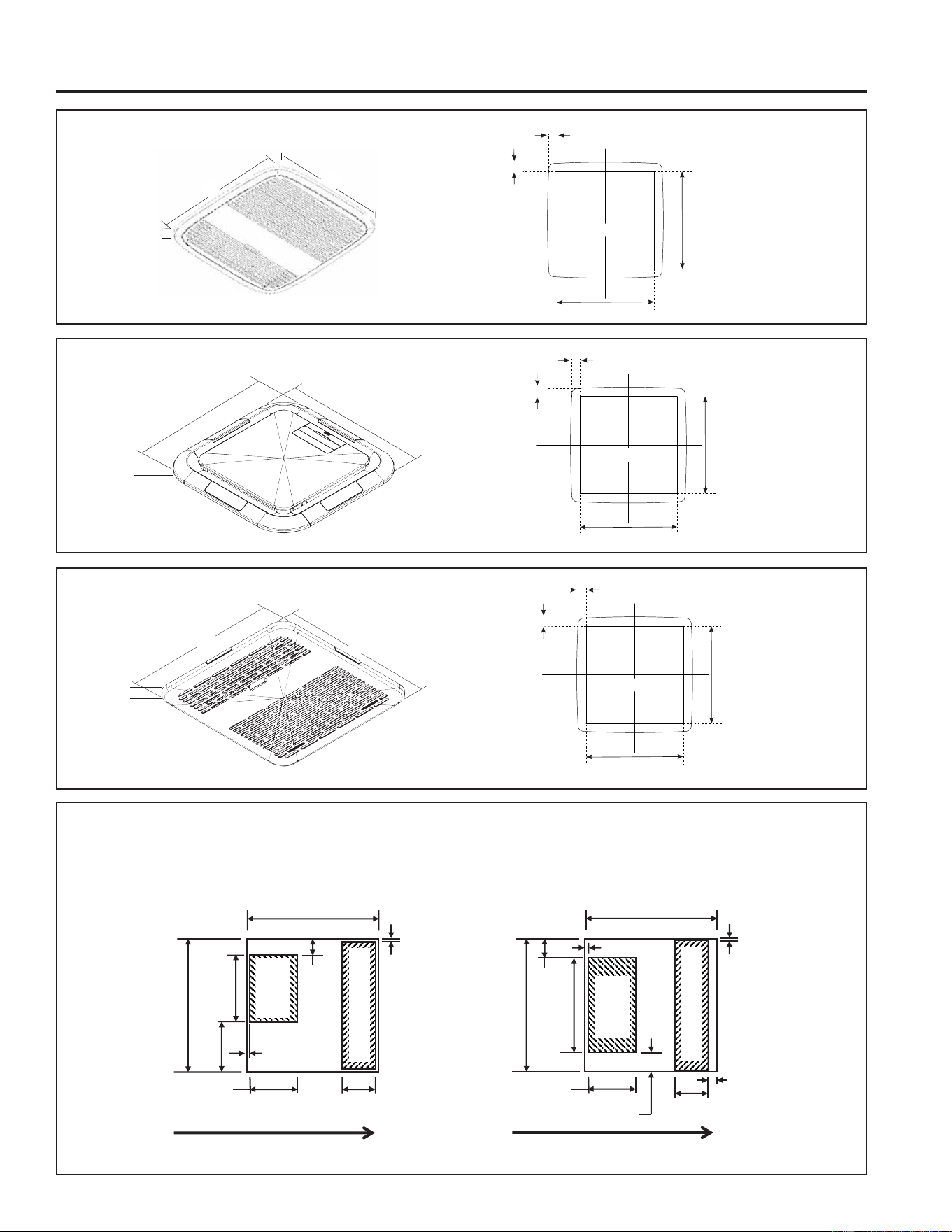
Figure 3: GE Appliances Indoor Non-Ducted Unit
(RGRMN)
Figure 4: GE Appliances Indoor Ducted Unit (RGRED)
Figure 5: GE Profile Indoor Non-Ductged Unit (RPREN)
Figure 6: GE Profile Indoor Ducted Unit (RPRED)
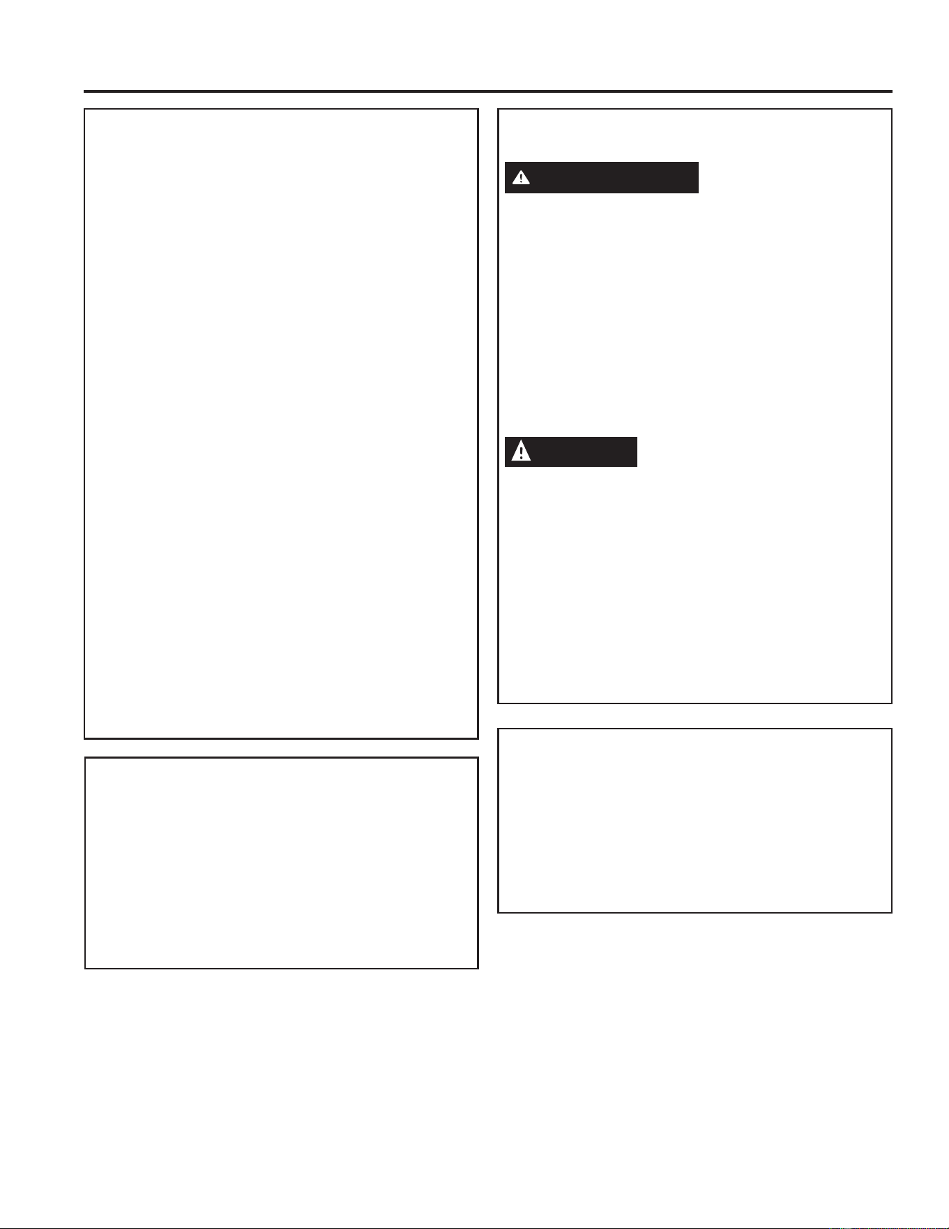
Figure 7: Guidelines for Top-Down Mounting
Figure 1: GE Appliances Outdoor Unit:
Figure 2: GE Profile Outdoor Unit:
WARNING
ELECTRICAL SHOCK HAZARD
Death or serious injury can result from failure to follow these instructions.
• Disconnect 115VAC and 12VDC power supply before beginning installation and/or servicing
• Ensure product is properly grounded according to the applicable codes
• Replace all parts and panels before operating
32.8”
26.2”
13.9”
18”
Center Line of unit
Keep at least 18” free of obstructions at rear of unit.
Roof opening
Front
13 - 3/4”
4 - 3/4”
21.238”
3.834”
14 - 3/8”
3 - 3/8”
14 - 3/8”
4”
2 - 5/8”
Roof opening
21”
21”
2-1/2”
INSTALLATION INSTRUCTIONS
1149-5000888 Rev. 5
Figure 7: Guidelines for Top-Down Mounting:
INSTALLATION INSTRUCTIONS
Figure 4: GE Appliances Indoor Ducted Unit:
Figure 5: GE Profile Indoor Non-Ducted Unit:
Figure 6: GE Profile Indoor Ducted Unit:
Roof Opening
14 - 3/8”
14 - 3/8”
1 - 1/16”
1 - 1/16”
Roof Opening
14 - 3/8”
14 - 3/8”
1 - 3/8”
1 - 3/8”
Roof Opening
14 - 3/8”
14 - 3/8”
1 - 3/8”
1 - 3/8”
Installation Instructions
21”
21”
4.1”
17.5”
17.5”
1.2”
3/4”
17”
17”
(6-3/4 in)
14-3/8 in
14-3/8 in
3/8 ± ¼ in
1-3/4 in MAX
4-7/8 ± ¼ in
4 ± ¼ in
¼ ± ¼ in
14-3/8 in
14-3/8 in
3/8 in ± ¼
in
2 in MAX
5 in ± ¼ in
(10-1/4 in)
3-5/8 ± ¼ in
3/8 ± ¼ in
1in MAX
2-1/8 in MAX
5-7/8in MAX
Standard Height Models (GRC/GRH)
TOP-DOWN VIEW
/RZ3UR¿OH0RGHOV3/&63/+6
TOP-DOWN VIEW
TOP AND
BOTTOM
3 SIDES
AIR
287/(7
AIR
287/(7
AIR INLET
AIR INLET
)52172)81,7 )52172)81,7
12 49-5000888 Rev.5
Installation Instructions
C. ELECTRICAL REQUIREMENTS
These models require a 115V, 60-Hz protected with
either a 15-amp or 20-amp time-delay fuse or circuit
breaker (see table 1 on page 4).
8VHDPLQLPXPRIVKHDWKHG$:*FRSSHUZLUH
with ground.
Be sure that 16” of supply wire is passed through the
framing. This ensures enough wire is available for an
easy connection in the junction box.
NOTE:
For the following indoor assembly installations,
proceed to the corresponding section:
RGRMN: Section E1, page 14
RGREN: Section E1, page 14
RPREN: Section E1, page 14
RGRED: Section F, page 16
RPRED: Section F, page 16
B. ROOF REQUIREMENTS AND
PREPARATION
If a preexisting roof vent opening will be used:
8QVFUHZDQGUHPRYHURRIYHQWIURP59
2. Seal all holes and seams with a weather resistant
sealant.
3. Measure the width and length of the vent opening.
If the opening doesn’t comply with the requirements
from section A, it must be resized.
If a preexisting opening will not be used, a new opening
will be cut through both the roof and ceiling of the RV.
7KLVRSHQLQJ0867EHEHWZHHQVWUXFWXUDOURRI
members.
2. Do NOT cut structural roof members to create
opening for this air conditioner. Doing so may cause
damage to RV and air conditioner.
3. Do NOT create a low spot on the RV roof. Water
can pool and may leak through the opening.
The square opening must be boxed with framing
at least 3/4” thick to withstand the load from the
compression bolts.
Be sure to provide an access hole for RV wiring
toward the front of the 14 ñ»” x 14 ñ»” opening.
Roof and RV structure at point of install must be
strong enough to support air conditioner without
any deflection. If in doubt, please contact your RV
manufacturer. Deflection will allow water to pool at the
air conditioner’s gasket, and may cause a leak.
D. PLACING UNIT ON ROOF
CAUTION
LIFTING HAZARD. Ensure proper
lifting methods and controls are
used when lifting unit to the RV roof. Failure to do so
can result in injury.
1. Remove unit from packaging and dispose of
packaging.
2. Do not slide the unit on its mounting gasket.
'DPDJHWRJDVNHWFDQFDXVHDOHDN8VLQJWZR
people, lift the unit and place it over the prepared
opening. The front of the unit must face the RV’s
direction of travel. Damage to condenser fan and
coil will occur if this instruction is not followed.
WARNING
It is important that these installation
instructions are read and understood before
installation and use.
Failure to securely install the unit to the RV before
moving the RV may result in personal injury or death.
Do not operate the unit or recreational vehicle until the
unit is fully secured on roof.
3. Bring the ceiling assembly with all provided
mounting hardware into the RV. If you are using an
indoor assembly, all work on the exterior of the RV
is now complete.
INSTALLATION INSTRUCTIONS

1349-5000888 Rev. 5
INSTALLATION INSTRUCTIONS
Installation Instructions
TOP-DOWN MOUNTING
1. If your roof has two individual openings as shown in Section A, Figure 7, proceed to step 1A. Otherwise,
proceed to step 1B.
1A. You will need to install accessory RGRFG1A foam gasket to prevent the inlet and outlet airflows from
mixing. Tilt your unit up and peel the adhesive release liner from the back of the RGRFG1A foam gasket.
Adhere the gasket to the bottom of the unit’s base pan between the air inlet and outlet openings.
1B. Tilt your unit up and position your baffle such that it separates inlet and outlet airflow without interfering
with the ductwork in your roof opening. Then, set your unit back down, maintaining the positioning
referenced in Section A.
2. Remove the outdoor shroud by unscrewing the 4 screws around the perimeter of the unit and place it off to the
side.
3. Remove the EPP Evaporator cover and store it with the shroud cover. Pull the 115VAC and the 12VDC power
supply cords as well as the thermostat wiring from the RV roof opening through the ovular air inlet opening at
the front of the air conditioner’s base-pan.
4. Identify the indented areas in the lower piece of the evaporator EPP Cover. These 4 locations are where you
will drive your lag bolts to secure the air conditioner to the RV’s roof.
5. If you are mounting into a wooden frame, use lag bolts rated for wood and torque to 35+/- 5 in-lbs. If you are
mounting into an aluminum frame, use lag bolts rated for metal and torque to 35 +/- 5 in-lbs.
6. 6HHWKH&RQWURO8VH&DUH0DQXDOIRUFRQQHFWLQJSRZHUWKHUPLVWRUVDQGDWKHUPRVWDWWR\RXUFRQWURO
7. With your control securely closed and fastened, slide it into the mounting bracket at the front of the unit. The
tabs that protrude from the side of the control should slide into the bracket’s cavity.
8. 8VHRIWKHVKHHWPHWDOVFUHZSURYLGHGZLWK\RXUFRQWUROWRVHFXUHLWWRWKHEUDFNHWYLDWKHSURWUXGLQJWDEV
9. Reinstall the EPP Evaporator cover, ensuring proper alignment to the EPP base. Failure to do this will result in
decreased performance from the air conditioner.
10. Reinstall the outdoor shroud by driving the 4 screws removed in step 2.
11. You have successfully installed your unit
14 49-5000888 Rev.5
Installation Instructions
E1. NON-DUCTED INSTALLATION
(RGRMN, RGREN, & RPREN)
1. From inside the RV, double check the gasket’s
position and alignment above the roof opening.
Adjust if necessary. The air conditioner can be
moved and adjusted by pushing upwards from
inside the RV.
2. Reach through the base pan and pull the electrical
power cord from the air conditioner through the
ceiling opening.
3. Measure ceiling to roof thickness.
4. Cut rows from the bottom of the foam baffle
according to the table below:
Ceiling to roof thickness (in) Rows to cut
Minimum Maximum
22.510
2.5 3 8
3.5 4 6
4.5 5 4
55.52
5.5 6 0
Best Practice:
Cut away one row at a time and check installation
position of baffle. With the top foam compressed onto
the air conditioner’s base pan, the bottom of the baffle
should be flush to the ceiling opening.
5. Place foam baffle into position between 2 retainer
plates.
6. Push the mounting template into the roof opening,
and begin hand-threading each of the 4 mounting
bolts through the nuts in the base pan.
7. Tighten the 4 bolts evenly to 35 ± 5 inch pounds
using a torque wrench at least rated for 0-60 in-lbs.
Even compression is required to prevent leaks
through the gasket.
STOP!
For RGRMN go to section E2 – Mechanical
Non-Ducted Wiring
For RGREN & RPREN go to section E3 – Electronic
Non-Ducted Wiring
E1. NON-DUCTED INSTALLATION
(RGRMN, RGREN, & RPREN)
(cont.)
8. Secure the ceiling panel to the mounting template
via 2 sheet metal screws per the 2 holes in the
filter cavity. The filter must be removed to install the
screws.
9. Applying pressure to the center of the ceiling panel,
drive two wood screws in the holes under the louver
located closest to the direct discharge guide. The
side discharge ports should be removed to allow
access to the mounting holes.
10. Drive the remaining 6 wood screws located under
the side discharge ports. Access the mounting
holes via the method in the previous step.
11. Reinstall the filter.
12. Installation is complete. Refer to “Controls” on
page 18 Before attempting to operate the air
conditioner.
INSTALLATION INSTRUCTIONS

1549-5000888 Rev. 5
INSTALLATION INSTRUCTIONS
Installation Instructions
E2. MECHANICAL NON-DUCTED
INSTALLATION (RGRMN_ _)
1. Remove the 4 and 3-pin connector cover from the
ceiling assembly by removing 2 screws.
2. Plug the cord with the 3 and 4-pin connector into the
respective receptacles on the mounting template.
3. Reinstall the 3 and 4-pin connector cover, routing
WKHFRUGWKURXJKWKH8VKDSHGRSHQLQJWDNLQJFDUH
not to pinch the wires.
8QLQVWDOOWKHMXQFWLRQER[FRYHUE\UHPRYLQJ
screws.
5. Route the 115 VAC power supply cord through the
2-screw strain relief of the ceiling assembly. Then,
tighten the strain relief, taking care not to damage
the wires.
8VLQJZLUHFRQQHFWRUVUDWHGIRU\RXUZLUHJDXJH
connect line to black, neutral to white, and ground to
green.
8VLQJHOHFWULFDOWDSHVHFXUHWKHFRQQHFWRUVWR
prevent any potential movement due to vehicle
vibration. If wire nuts are used, be sure to apply the
tape in the direction the nut was tightened so as to
not unintentionally loosen the connection.
8. Position the power supply wires and connections
inside the junction box and reinstall the junction box
cover.
9. Align the plastic ceiling panel to the mounting
template using the control knob posts as guides.
10. Install the 2 control knobs, ensuring the D-shaped
contour is properly aligned on the posts.
11. Proceed to step 8 of Section E1.
E3. ELECTRONIC NON-DUCTED
INSTALLATION (RGREN_ _ &
RPREN__)
8QLQVWDOOWKHEODQNLQJSODWHIURPWKHPRXQWLQJ
template by removing 3 screws
2. Mount the main control box (RGREC_A) to the
mounting template using 2 screws.
3. Remove 3 screws from the base of the main control
box, allowing the base to hinge open. The control
board is now visible and accessible.
4. Route the 115 VAC power supply cord through the
strain relief of the control box. Then, tighten the
strain relief, taking care not to damage the wires.
8VLQJZLUHFRQQHFWRUVUDWHGIRU\RXUZLUHJDXJH
connect line to blue, neutral to white, and ground to
green/yellow.
8VLQJHOHFWULFDOWDSHVHFXUHWKHFRQQHFWRUVWR
prevent any potential movement due to vehicle
vibration. If wire nuts are used, be sure to apply the
tape in the direction the nut was tightened so as to
not unintentionally loosen the connection.
E3. ELECTRONIC NON-DUCTED
INSTALLATION (RGREN_ _ &
RPREN__)
(cont.)
7. Route the 3 and 4-pin connectors from the outdoor
XQLWWKURXJKWKH8VKDSHGRSHQLQJRQWKHFRQWURO
box. Mate these connectors to their corresponding
plugs on the control board.
8. Connect the 12VDC power supply wire and ground
wire coming from your RV to the removable 2
pin connector terminals labeled “12V” and “GND”
UHVSHFWLYHO\6HHWKHFRQWURO8VHDQG&DUHPDQXDO
for connecting your specific control to your wall
thermostat.
9. Your unit will come with 2 thermistors pre-installed
in your air conditioning unit that need to be
connected to the main control board. The indoor coil
freeze sensor is a 2-pin connector that needs to be
plugged into the T2 terminal on the control board
and the indoor air outlet temperature sensor is a
3-pin connector that needs to be plugged into the
T3 connector on the main control board. Heat pump
models also have a 4-pin connector that contains
an outdoor coil thermistor and outdoor ambient
temperature thermistor—this needs to be connected
to the T4/T5 terminal on the main control board.
Failure to make the specified connections will result
in fault codes and can result in lack of function of
your unit.
10. If you are using the RGRES1A room sensor with
your air conditioning unit, you will need to connect
the sensor to the main control board via the
removable 2-pin terminal labeled “LS”.
11. OPTIONAL: If you want your air conditioning unit
to be connected to your RV’s load shed system
(Not included with all RVs), you will need to
connect your load shed system to the main control
board. If you are using an RGREC1A control,
connect the load shed system via the removable
2-pin connector labeled “LS”. If you are using an
RGREC2A control, connect the load shed system
via the terminal on the detachable 8-pin connector
labeled “LS”.
12. OPTIONAL: If you have a furnace you would
like to control via your thermostat, connect your
IXUQDFHWRWKHWZRWHUPLQDOVODEHOHG³)85´RQWKH
removable 4-pin connector. Refer to your furnace’s
owner’s manual..
13. OPTIONAL: All controls have the option for auto
generator start functionality. If you want to enable
this function, connect your generator to the two
terminals labeled “GEN” on the removable 4-pin
connector.
14. Keeping all connections inside the control box,
URXWHWKHZLUHVWKURXJKWKH8VKDSHGRSHQLQJ
on the side. Then, taking care not to pinch/crush
any wires, rotate the base of the main control box
upward and reinstall the 3 screws removed in Step
3 to seal the control box.
16 49-5000888 Rev.5
Installation Instructions
E3. ELECTRONIC NON-DUCTED
INSTALLATION (RGREN_ _ &
RPREN__)
(cont.)
15. Install the cover plate via 3 screws that attach
to the mounting template and 2 screws that that
attach to the main control box.
16. For RGREN, proceed to step 8 of Section E1. For
RPREN proceed to step 16 of Section E3
17. Secure the ceiling panel base to the mounting
template using 4 sheet metal screws
18. Install your filter and filter retainer into the filter
tray.
19. Aligning the filter tray with the corresponding
grooves in the ceiling panel base, slide the filter
tray into position
8VLQJWKHIRXUHPERVVHGJXLGHIHDWXUHVRQWKH
ceiling panel base, install the ceiling panel cover
21. Installation is complete. Refer to thermostat
operating instructions before attempting to
operate.
F. ELECTRONIC DUCTED
(RGREN & RPRED)
INSTALLATION
(cont.)
7. Mount the dividing baffle to the framing timber using
two screws on each side, creating an airtight seal.
For additional sealing, use aluminum tape to seal
any potential leaks between the framing timber and
the baffle.
8. Mount the Main Control Box (RGREC_ _) to the
mounting template using four screws.
9. Remove three screws from main control box,
allowing the bottom section to hinge open. Control
board is now visible and accessible.
10. Route the 115 VAC power cord through the strain
relief of the control box. Tighten the strain relief,
making sure not to damage the wires.
8VLQJZLUHFRQQHFWRUVUDWHGIRU\RXUZLUHJDXJH
connect line to blue, neutral to white, and ground
to green/yellow.
8VLQJHOHFWULFDOWDSHVHFXUHWKHFRQQHFWRUVWR
prevent any potential movement due to vehicle
vibration.
13. Route the 3 and 4-pin connectors from the outdoor
XQLWWKURXJKWKH8VKDSHGRSHQLQJRQWKHFRQWURO
box. Mate these connectors to their corresponding
plugs on the control board.
14. Connect the 12VDC power supply wire and
ground wire coming from your RV to the
removable 2 pin connector terminals labeled “12V”
DQG³*1'´UHVSHFWLYHO\6HHWKHFRQWURO8VHDQG
Care manual for connecting your specific control
to your wall thermostat.
15. Your unit will come with 2 thermistors pre-installed
in your air conditioning unit that need to be
connected to the main control board. The indoor
coil freeze sensor is a 2-pin connector that needs
to be plugged into the T2 terminal on the control
board and the indoor air outlet temperature sensor
is a 3-pin connector that needs to be plugged into
the T3 connector on the main control board. Heat
pump models also have a 4-pin connector that
contains an outdoor coil temperature and outdoor
ambient temperature thermistor—this needs to
be connected to the T4/T5 terminal on the main
control board. Failure to make the specified
connections will result in fault codes and can
result in lack of function of your unit.
F.
ELECTRONIC DUCTED
(RGRED & RPRED) INSTALLATION
1. From inside the RV, double check the gasket’s
position and alignment above the roof opening.
Adjust if necessary. The air conditioner can be
moved and adjusted by pushing upwards from
inside the RV.
2. Reach through the base pan and pull the electrical
power cord from the air conditioner through the
ceiling opening.
3. Push the ceiling mounting template into the roof
opening and begin hand-threading each of the 4
mounting bolts through the nuts in the base pan.
4. Tighten the 4 bolts evenly to 35 ± 5 inch pounds
using a torque wrench at least rated for 0-60 in-lbs.
Even compression is required to prevent leaks
through the gasket.
5. Place dividing baffle into position on the ceiling
assembly. Ensure baffle is pressed against the
base pan, forming an airtight seal.
6. Mount the dividing baffle to the mounting template
using three screws.
INSTALLATION INSTRUCTIONS

1749-5000888 Rev. 5
INSTALLATION INSTRUCTIONS
F. ELECTRONIC DUCTED (RGRED & RPRED) INSTALLATION (cont.)
16. If you are using the RGRES1A room sensor with
your air conditioning unit, you will need to connect
the sensor to the main control board via the
removable 2-pin terminal labeled “LS”.
17. OPTIONAL: If you want your air conditioning unit
to be connected to your RV’s load shed system
(Not included with all RVs), you will need to
connect your load shed system to the main control
board. If you are using an RGREC1A control,
connect the load shed system via the removable
2-pin connector labeled “LS”. If you are using an
RGREC2A control, connect the load shed system
via the terminal on the detachable 8-pin connector
labeled “LS”.
18. OPTIONAL: If you have a furnace you would like to
control via your thermostat, connect your furnace to
WKHWZRWHUPLQDOVODEHOHG³)85´RQWKHUHPRYDEOH
4-pin connector. Refer to your furnace’s owner’s
manual.
19. Keeping all connections inside the control box,
URXWHWKHZLUHVWKURXJKWKH8VKDSHGRSHQLQJ
on the side. Then, taking care not to pinch/crush
any wires, rotate the base of the main control box
upward and reinstall the 3 screws removed in Step
9 to seal the control box.
20. For RGRED, align the plastic ceiling panel to the
mounting template. For RPRED, align the ceiling
panel base to the mounting template.
8VLQJWKHSURYLGHGVKHHWPHWDOVFUHZVVHFXUH
the ceiling panel or ceiling panel base to the
mounting template. The filter and filter cover must
be removed to install these screws.
22. For RGRED, install the filter and filter cover by
depressing the single tab at the middle of the filter
cover and snap it into the filter cavity. Next install
the left and right screw cover by inserting them into
their respective cavities.
23. For RPRED, install the filter retainer with the filter
into the ceiling panel base by sliding it under two
tabs on the ceiling panel base and then rotating
downwards. Then align the ceiling panel cover via
the slide knob and push upward in the direction
of the ceiling to snap the ceiling panel cover into
place.
24. Installation is complete. Refer to thermostat
operating instructions before attempting to operate.
25. OPTIONAL: All controls have the option for auto
generator start functionality. If you want to enable
this function, connect your generator the two
terminals labeled “GEN” on the removable 4-pin
connector.
Installation Instructions
18 49-5000888 Rev.5
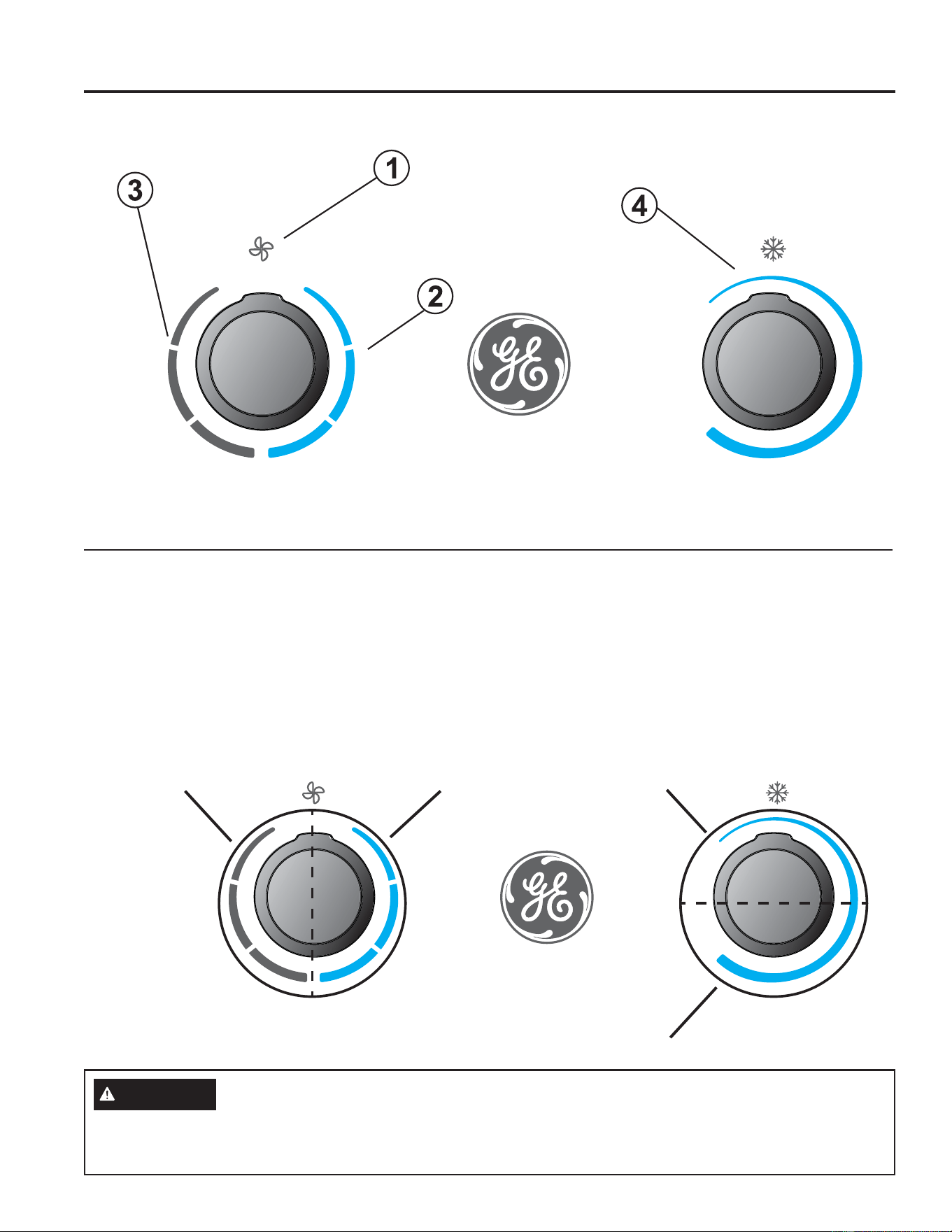
Controls
Controls
1. Power Off
The air conditioner is off in this position.
2. Air Conditioning Modes
In these positions, the compressor and fans will run
to provide cold air. The three modes correspond to
low, medium, and high fan speeds.
3. Fan Only Modes
In these modes, the fans will run to circulate air
in the RV. The three modes correspond to low,
medium, and high fan speeds.
4. Temperature Selection
This knob determines the room set point
temperature. Turn this knob to increase or decrease
how cold the air conditioner will make the room.
Features and appearance will vary.
Air Conditioner Controls
CAUTION
To prevent circuit breaker from tripping, wait a minimum of 3 minutes between turning the compressor off and
then back on (i.e. wait 3 minutes before moving the dial from position 1A to 1B back to 1A or moving from position
2A to 2B back to 2A (pictured above)
Ma
x
Cool
With A
C
O
ff
F
an Speed
T
emperature
Ma
x
Coo
l
W
ith A
C
O
f
f
F
an S
p
eed
T
em
p
eratur
e
Position
2B
Position
2A
Position
1A
Position
1B
USING THE AIR CONDITIONER
1949-5000888 Rev. 5
USING THE AIR CONDITIONER
Using the Air Conditioner
IMPORTANT:
• When you turn off the air conditioner, wait at least 3 minutes before turning it back on. This prevents the compressor
from overloading. This 3 minute delay also applies when switching from cool mode to fan and back.
• Do not operate your air conditioner in the Cool mode when the outside temperature is below 60°F (15° C). The
inside evaporator coil may freeze up, and the air conditioner will not operate properly.
Air Direction
8VHWKHOHYHUWRRSHQRUFORVHYHQWRQIDFHRIFRQWURO
panel.
Open or close 4 side ports to adjust airflow from the air
conditioner.
Front View
Lever is located
between the two
knobs
Normal Operating Sounds
When your air conditioner is operating normally, you may hear sounds such as:
Ŷ'URSOHWVRIZDWHUKLWWLQJWKHFRQGHQVHUFDXVLQJDSLQJLQJRUFOLFNLQJVRXQG7KHZDWHUGURSOHWVKHOSFRROWKH
condenser.
Ŷ$LUPRYHPHQWIURPWKHIDQ
Ŷ&OLFNVIURPWKHFRQWUROF\FOLQJ
Ŷ$KXPRUSXOVDWLQJQRLVHFDXVHGE\WKHFRPSUHVVRUF\FOLQJRQDQGRII
20 49-5000888 Rev.5
CARE AND CLEANING
Care and Cleaning
Indoor Panel
Turn the air conditioner off and disconnect power from the
air conditioner before cleaning.
To clean, use water and a mild detergent. Do not use
bleach or abrasives.
Annual Maintenance
Your air conditioner needs annual maintenance to help
ensure steady, top performance throughout the year.
Call your local authorized dealer to schedule an annual
checkup. The expense of an annual inspection is your
responsibility.
Air Filter
The air filter should be checked every 2 weeks and
cleaned if necessary.
DO NOT operate the air conditioner without a filter
because dirt and lint will clog it and reduce performance.
Cleaning the Air Filter
1. Turn off the air conditioner.
2. Remove the air filter cover per the following figures to
gain access to the filter.
8VHDYDFXXPFOHDQHUWRFOHDQDLUILOWHU,IWKHDLU
filter is very dirty, wash it in warm water with a mild
detergent. Do not wash the air filter in the dishwasher
or use any chemical cleaners. Air dry the air filter
completely before replacing to ensure maximum
efficiency.
4. Reassemble the air filter to the grill.
5. Carefully reassemble the grill and filter assembly to
the main panel.
6. Turn on the air conditioner.
NOTE: RPREN and RPRED assemblies use a merv
6 filter which should be periodically checked and
maintained to be debris free.
Push both tabs toward the GE logo to release the cover.
RPRED
RPREN

2149-5000888 Rev. 5
TROUBLESHOOTING
Troubleshooting Tips... Before you call for service
Save time and money! Review the charts on the following pages first and you may not need to call for service.
Problem Possible Cause What To Do
Air Conditioner
does not operate
An RV fuse has blown, or circuit
breaker has tripped.
Replace the fuse or reset the circuit breaker. If the problem
continues, call an electrician. See “Electrical Requirements.”
The mode setting is in the OFF
position.
Press POWER or turn the Mode control to an active setting.
The local power has failed. Wait for power to be restored.
Air conditioner
blows fuses
or trips circuit
breakers
Too many appliances are being used
on the same circuit.
8QSOXJRUUHORFDWHDSSOLDQFHVWKDWVKDUHWKHVDPHFLUFXLW
Time-delay fuse or circuit breaker of
the wrong capacity is being used.
Replace with a time-delay fuse or circuit breaker of the
correct capacity. See “Electrical Requirements.”
You are trying to restart the air
conditioner too soon after turning off
the air conditioner.
Wait at least 3 minutes after turning off the air conditioner
before trying to restart the air conditioner.
Air conditioner
seems to run too
much
The air conditioner is in a heavily
occupied room, or heat-producing
appliances are in use in the room.
8VHH[KDXVWYHQWIDQVZKLOHFRRNLQJRUEDWKLQJDQGWU\QRW
to use heat producing appliances during the hottest part of
the day. A higher capacity air conditioner may be required
depending on the size of the room being cooled.
Air conditioner
cycles on and off
too much or does
not cool room in
cooling mode
The air conditioner is not properly
sized for your RV.
Check the cooling capabilities of your RV air conditioner.
The filter is dirty or obstructed by
debris.
Clean or replace the filter.
There is excessive heat or moisture
(open container cooking, showers,
etc.) in the room.
8VHDIDQWRH[KDXVWKHDWRUPRLVWXUHIURPWKHURRP7U\QRW
to use heat-producing appliances during the hottest part of
the day.
The louvers or ducts are closed. Make sure louvers are open.
The outside temperature is below
60°F (15°C).
Do not try to operate your air conditioner in the cooling mode
when the outside temperature is below 60°F (15°C).
The temperature of the room you are
trying to cool is extremely hot.
Allow extra time for the air conditioner to cool off a very hot
room.
Windows or doors to the outside are
open.
Close all windows and doors.
The Temperature control is not at a
cool enough setting.
Adjust the TEMP control to a cooler setting by pressing the
minus button to reduce the temperature. Set the Fan Speed
control to the highest setting.
Wall thermostat improperly installed Verify proper installation of Wall Thermostat per installation
instructions (pg. 5 …not on exterior wall or in direct
sunlight… …in an area affected by a vent or duct…)
Water drips from
cabinet into your
house
The indoor coil may be frozen. De-ice by running the fan only until clear.
The air conditioner’s mounting gasket
may not be sealed against the roof.
Check mounting bolts and tighten to 35 ± 5 in-lbs if
necessary.
AC blows fuses
or trips circuit
breaker
The condenser coil or condenser fan
is blocked or obstructed
Remove any obstructing material or debris from the
condenser coil or the condenser fan

22 49-5000888 Rev.5
SCHEMATIC DIAGRAMS
Schematic Diagrams
AC WIRING DIAGRAM
NOTE
3mm
3mm
WIRE COLOR
CONNECTOR
From
①
to
ĺ
,and to
,one to one.
B
1 3
Y/G
W
1
2
3
4
R
OR
①②③
1
2
3
④
GR
Y
0011526311A
3
1
Y/G:YELLOW/GREEN
B :BLACK
W :WHITE
R :RED
BL:BLUE
Y :YELLOW
OR:ORANGE
BR:BROWN
GR:GREY
CAP.
~
R
C
M
S
COMP.
R
W
W
B
B
B
3
1
W
W
D
W
W
ID FAN
MOTOR
L
M
H
~
M
N
Y/G
CAP.
③①
W
OR
Y
R
BR BL
N
M
~
Y/G
OD FAN
MOTOR
BRBL
GR
W
B
④
GR
C
1
2
GR
W
CAP.
1
2
1
2
W
Y/G
W
B
OPTIONAL
CONDENSATE
PUMP
②
120mm
80mm
3mm
3mm
HP WIRING DIAGRAM
NOTE
WIRE COLOR
CONNECTOR
From
①
to
ĺ
,and to
,one to one.
3
1
B
1 3
Y/G
W
1
2
3
4
R
BL
OR
①
②
③
1
2
3
④
GR
0011526291A
Y/G:YELLOW/GREEN
B :BLACK
W :WHITE
R :RED
BL:BLUE
Y :YELLOW
OR:ORANGE
BR:BROWN
GR:GREY
CAP.
~
R
C
M
S
COMP.
R
W
W
B
B
B
3
1
W
W
D
W
W
ID FAN
MOTOR
L
M
H
~
M
N
Y/G
CAP.
③①
W
OR
Y
R
BR BL
N
M
~
Y/G
OD FAN
MOTOR
BRBL
GR
W
B
④
GR
C
1
2
4-WAY
BL
BL
②
BL
GR
W
CAP.
1
2
1
2
W
Y/G
W
B
OPTIONAL
CONDENSATE
PUMP
120mm
80mm
2349-5000888 Rev. 5
LIMITED WARRANTY
GE Appliances Air Conditioner Limited Warranty
Ŷ,PSURSHULQVWDOODWLRQGHOLYHU\RUPDLQWHQDQFH,I\RX
have an installation problem, or if the air conditioner
is of improper cooling capacity for the intended use,
contact your dealer or installer. You are responsible for
providing adequate electrical connecting facilities.
Ŷ)DLOXUHRIWKHSURGXFWUHVXOWLQJIURPPRGLILFDWLRQV
to the product or due to unreasonable use including
failure to provide reasonable and necessary
maintenance.
Ŷ/DERUQHFHVVDU\WRPRYHWKHXQLWWRDORFDWLRQZKHUHLW
is accessible for service by an individual technician.
Ŷ5HSODFHPHQWRIKRXVHIXVHVRUUHVHWWLQJRIFLUFXLW
breakers.
Ŷ'DPDJHWRWKHSURGXFWFDXVHGE\LPSURSHUSRZHU
supply voltage, accident, fire, floods or acts of God.
Ŷ,QFLGHQWDORUFRQVHTXHQWLDOGDPDJHFDXVHGE\
possible defects with this air conditioner.
Ŷ'DPDJHFDXVHGDIWHUGHOLYHU\
What GE Appliances Will Not Cover:
This limited warranty is extended to the original purchaser and any succeeding owner for products purchased
IRU59XVHZLWKLQWKH86$DQG&DQDGD,IWKHSURGXFWLVORFDWHGLQDQDUHDZKHUHVHUYLFHE\DQDXWKRUL]HG59
servicer is not available, you may be required to bring the product to an authorized service location for service.
Authorized GE Service location for service.
Some states do not allow the exclusion or limitation of incidental or consequential damages. This limited warranty
gives you specific legal rights, and you may also have other rights which vary from state to state. To know what
your legal rights are, consult your local or state consumer affairs office or your state’s Attorney General.
Warrantor: GE Appliances, a Haier company
Louisville, KY 40225
All warranty service must be provided by certified RV Service Centers.
To schedule service call 1-866.835.0179
Have serial number and model number available when calling for service.
EXCLUSION OF IMPLIED WARRANTIES—Your sole and exclusive remedy is product repair as provided in
this Limited Warranty. Any implied warranties, including the implied warranties of merchantability or fitness
for a particular purpose, are limited to two years or the shortest period allowed by law.
For The Period Of: GE Appliances Will Replace:
Two Years
From the date of the
original purchase
Any part of the air conditioner which fails due to a defect in materials or workmanship.
During this limited two-year warranty, GE Appliances will also cover all labor and
related service to replace the defective part.
Staple your receipt here. Proof of the original purchase
date is needed to obtain service under the warranty.

24 49-5000888 Rev.5
Consumer Support
CONSUMER SUPPORT
GE Appliances Website
Have a question or need assistance with your appliance? Try the GE Appliances Website 24 hours a day, any day
of the year! You can also shop for more great GE Appliances products and take advantage of all our on-line support
VHUYLFHVGHVLJQHGIRU\RXUFRQYHQLHQFH,QWKH86GEAppliances.com
Register Your Appliance
Register your new appliance on-line at your convenience! Timely product registration will allow for enhanced
communication and prompt service under the terms of your warranty, should the need arise. You may also mail in
WKHSUHSULQWHGUHJLVWUDWLRQFDUGLQFOXGHGLQWKHSDFNLQJPDWHULDO,QWKH86GEAppliances.com/register
Schedule Service
Visit us at: GEAppliances.com/service or call 1.866.835.0179 during normal business hours.
Extended Warranties
Purchase a GE Appliances extended warranty and learn about special discounts that are available while your
warranty is still in effect. You can purchase it on-line anytime. GE Appliances Services will still be there after your
ZDUUDQW\H[SLUHV,QWKH86GEAppliances.com/extended-warranty or call 800.626.2224 during normal
business hours.
Parts and Accessories
Individuals qualified to service their own appliances can have parts or accessories sent directly to their homes
(VISA, MasterCard and Discover cards are accepted). Order on-line today 24 hours every day.
,QWKH86GEApplianceparts.com or by phone at 877.959.8688 during normal business hours.
Instructions contained in this manual cover procedures to be performed by any user. Other servicing
generally should be referred to qualified service personnel. Caution must be exercised, since improper
servicing may cause unsafe operation.
Contact Us
If you are not satisfied with the service you receive from GE Appliances, contact us on our Website with all the
details including your phone number, or write to:
General Manager, Customer Relations | GE Appliances, Appliance Park | Louisville, KY 40225
GEAppliances.com/contact

49-5000888 Rev. 5
GE est une marque déposée de General Electric Company. Fabriqué sous licence de marque.
CLIMATISEUR
individuel
MANUEL
D’UTILISATION
Unités de toit :
Hauteur standard
GRCS13XHH_
GRHS13XHH_
GRCS13XAH_
GRHS13XAH_
GRCS15XAH_
GRHS15XAH_
Profile Bas
PLCS13XHH_
PLHS13XHH_
PLCS13XAH_
PLHS13XAH_
PLCS15XAH_
PLHS15XAH_
Assemblages intérieurs :
RPRED_ _
RPREN_ _
RGRED_ _
RGREN_ _
RGRMN_ _
FRANÇAIS
Écrivez le modèle et les numéros de
série ici:
Modèle # ______________
Serial # _______________
Vous pouvez les trouver sur une
étiquette sur le climatiseur.
INFORMATION DE SÉCURITÉ ...3
INSTRUCTIONS D’INSTALLATION
Avant de commencer ..................4
Outils dont vous pouvez avoir besoin. . . . 4
RGRMN_ _ Pièces incluses ..............5
RGREN_ _ Pièces incluses ..............6
RGRED_ _ Pièces incluses. . . . . . . . . . . . . . .7
RPREN_ _ Pièces incluses ...............8
RPRED_ _ Pièces incluses ...............9
Exigences et détermination de
l’emplacement d’installation sur le toit . .10
Exigences et préparation du toit ........12
Exigences électriques .................12
Mise en place de l’appareil sur le toit ....12
Installation de l’appareil ...............14
Instr. Pour électricité ..................15
UTILISANT LE CONDITIONNEUR
D’AIR
Commandes .........................18
Orientation de l’air. . . . . . . . . . . . . . . . . . . 19
Ces phénomènes sont normaux .........19
ENTRETIEN ET NETTOYAGE
Panneau intérieur .................... 20
Filtre à air. . . . . . . . . . . . . . . . . . ....... 20
Maintenance annuelle ................ 20
CONSEILS DE DÉPANNAGE ....21
SCHÉMAS DE PRINCIPE ........22
GARANTIE LIMITÉE .............23
SOUTIEN AU
CONSOMMATEUR .............. 24
49-5000888 Rev. 5 05-25

2 49-5000888 Rev. 5
NOUS VOUS REMERCIONS D’ACCUEILLIR GE APPLIANCES CHEZ VOUS RV
Que vous ayez grandi avec GE Appliances ou qu’il s’agisse de votre première acquisition, nous
sommes heureux de vous accueillir dans notre famille.
Nous sommes fiers du savoir-faire, de l’innovation et de l’esthétique qui composent chaque appareil
GE Appliances, et nous pensons que vous le serez aussi. Dans cette optique, nous vous rappelons
que l’enregistrement de votre électroménager vous assure la communication de renseignements
importants sur le produit et la garantie lorsque vous en avez besoin.
Enregistrez votre électroménager GE en ligne dès maintenant. Des sites Web et des numéros de
téléphone utiles figurent dans la section Soutien au consommateur de ce manuel d’utilisation.
349-5000888 Rev. 5
AVERTISSEMENT
Pour votre sécurité, vous devez suivre les instructions de ce manuel pour réduire les
risques d’incendie, d’explosion, de choc électrique, de dommage à la propriété, de blessure ou de décès.
Ŷ1¶XWLOLVH]FHWDSSDUHLOTXHSRXUVRQXVDJHSUpYXWHOTXH
décrit dans le Manuel de l’utilisateur.
Ŷ9RXVGHYH]ELHQPRQWHUFHFRQGLWLRQQHXUFRQIRUPpPHQW
aux Instructions de montage, avant de l’utiliser.
Ŷ5HPSODFH]LPPpGLDWHPHQWWRXWFRUGRQG¶DOLPHQWDWLRQ
abîmé ou endommagé. Un cordon d’alimentation électrique
endommagé ne doit pas être réparé mais plutôt remplacé
par un autre cordon d’alimentation obtenu du fabricant.
N’utilisez pas un cordon d’alimentation qui montre des
fissures ou des signes d’abrasion sur sa longueur ou encore
près de la prise ou du connecteur.
ŶeWHLJQH]O¶DSSDUHLOHWGpEUDQFKH]WRXWHVOHVVRXUFHV
d’alimentation du véhicule avant d’effectuer le nettoyage ou
les réparations.
Ŷ$ILQGHSUpYHQLUOHULVTXHGHEOHVVXUHRXGHGRPPDJHjOD
propriété, le climatiseur doit être réparé par un technicien
TXDOLILpVHXOHPHQW&HOXLFLGRLWGpWHQLUXQFHUWLILFDWjMRXU
valide attribué par un organisme d’évaluation de l’industrie
TXLVDQFWLRQQHVDFRPSpWHQFHjPDQLSXOHUGHVIULJRULJqQHV
d’une manière sûre, en conformité avec une norme
d’évaluation reconnue par l’industrie.
Ŷ3RXUYRWUHVpFXULWp«QHUDQJH]MDPDLVRXQ¶XWLOLVH]MDPDLV
des matériaux combustibles, de l’essence ou d’autres
YDSHXUVRXOLTXLGHVLQIODPPDEOHVjSUR[LPLWpGHFHW
appareil ou de tout autre appareil électroménager.
Ŷ7RXVOHVFRQGLWLRQQHXUVFRQWLHQQHQWGHVIOXLGHVIULJRULJqQHV
qui, en vertu de la loi fédérale, doivent être retirés avant la
mise au rebut de l’appareil. Si vous vous débarrassez d’un
vieil appareil contenant des fluides frigorigènes, renseignez-
vous sur la façon de faire auprès de l’entreprise qui
s’occupe de la mise au rebut.
Ŷ&HVV\VWqPHVGHFOLPDWLVDWLRQ5H[LJHQWTXHOHV
entrepreneurs et les techniciens utilisent des outils, des
équipements et des normes de sécurité approuvés pour ce
W\SHGHUpIULJpUDQW1¶XWLOLVH]3$6XQpTXLSHPHQWFHUWLILp
pour d’autres réfrigérants seulement.
Ŷ&HWDSSDUHLOQ¶HVWSDVGHVWLQpjrWUHXWLOLVpSDUGHV
personnes (y compris des enfants) dont les capacités
physiques, sensorielles ou mentales sont réduites, ou
dont l’expérience et les connaissances sont insuffisantes,
jPRLQVTX¶HOOHVQHVRLHQWVRXVVXUYHLOODQFHRXTX¶HOOHV
Q¶DLHQWUHoXGHVLQVWUXFWLRQVTXDQWjO¶XWLOLVDWLRQGHO¶DSSDUHLO
par une personne responsable de leur sécurité.
LIRE ET CONSERVER CES INSTRUCTIONS
INFORMATION DE SÉCURITÉ
INFORMATION DE SÉCURITÉ IMPORTANTES
LISEZ TOUTES LES DIRECTIVES AVANT D'UTILISER L'APPAREIL
Risque d’incendie ou d’explosion. Cet appareil contient un
réfrigérant inflammable. Des mesures de sécurité supplémentaires
doivent être observées.
Ŷ1¶XWLOLVH]SDVGHPR\HQVYLVDQWjDFFpOpUHUOHGpJLYUDJH
ou le nettoyage autres que ceux recommandés par le
fabricant.
Ŷ/¶DSSDUHLOGRLWrWUHHQWUHSRVpGDQVXQHSLqFHGpSRXUYXH
de sources d’allumage fonctionnant en permanence (par
H[HPSOHIODPPHVQXHVDSSDUHLOjJD]RXUDGLDWHXU
électrique en fonctionnement.
Ŷ$EVWHQH]YRXVGHSHUFHURXGHEUOHUODWXEXOXUHGH
réfrigérant. Sachez que les réfrigérants peuvent être
inodores.
Ŷ*DUGH]OHVRULILFHVGHYHQWLODWLRQOLEUHVGHWRXWH
obstruction.
Ŷ/RUVGHODPDQLSXODWLRQGHO¶LQVWDOODWLRQHWGHO¶XWLOLVDWLRQ
GHO¶DSSDUHLOYHLOOH]jQHSDVHQGRPPDJHUODWXEXOXUHGH
réfrigérant.
Ŷ1HSHUFH]SDVGHWURXGDQVO¶DSSDUHLO
Ŷ/¶HQWUHWLHQOHQHWWR\DJHHWOHVUpSDUDWLRQVGRLYHQWrWUH
effectués uniquement par des techniciens dûment formés
pour manipuler des réfrigérants inflammables.
Ŷ*($SSOLDQFHVQHSUHQGSDVHQFKDUJHODUpSDUDWLRQGHV
FRPSRVDQWVpWDQFKHVGXV\VWqPHF¶HVWjGLUHGHVSLqFHV
contenant du réfrigérant) dans le climatiseur.
Ŷ0HWWH]OHFOLPDWLVHXUDXUHEXWFRQIRUPpPHQWDX[
UpJOHPHQWDWLRQVIpGpUDOHHWORFDOH/HVUpIULJpUDQWV
inflammables exigent des procédures de mise au rebut
spéciales. Contactez les autorités locales pour la mise au
rebut écologique de votre climatiseur.
3RXUSOXVG¶LQIRUPDWLRQVVXUOHUHF\FODJHGHVDSSDUHLOVUHQGH]YRXVVXUOHVLWHGEAppliances.com/recycling.
AVERTISSEMENT
A2L
4 49-5000888 Rev. 5
Connaissances générales
AVANT DE COMMENCER
Lisez ces instructions attentivement et en totalité.
•
Conservez ces instructions pour l’inspecteur local.
•
Observez tous les codes et règlements en vigueur.
• Note au monteur – Conservez le Manuel du propriétaire.
• Note au consommateur – Conservez ces instructions
pour consultation ultérieure.
• Niveau de compétence – /¶LQVWDOODWLRQGHFHWDSSDUHLO
requiert un technicien de véhicule récréatif qualifié.
• Temps d’exécution – Environ 1 heure
• Nous recommandons que l’installation de ce produit soit
effectuée par deux personnes.
/DUHVSRQVDELOLWpGHO¶H[DFWLWXGHGHO¶LQVWDOODWLRQLQFRPEHj
l’installateur.
/DJDUDQWLHQHFRXYUHSDVOHVGpIHFWXRVLWpVGXSURGXLW
causées par une installation inadéquate.
9RXVGHYH]XWLOLVHUWRXWHVOHVSLqFHVIRXUQLHVHWVXLYUHOHV
procédures appropriées qui figurent dans ces instructions
lors de l’installation de ce climatiseur.
Questions? Composez le 1.800.361.3400 ou visitez notre site web à : electromenagersge.ca
OUTILS DONT VOUS POUVEZ
AVOIR BESOIN
7RXUQHYLVjWrWH3KLOOLSV
0qWUHjUXEDQRXULGJH
Crayon
Niveau
Scissors ou couteau
3HUFHXVHHWIRUHWSR
ATTENTION
3UHQH]JDUGHDX[ERUGVDFpUpVSRXUpYLWHUOHVEOHVVXUHV
Deux personnes sont nécessaires pour soulever ce
climatiseur.
Du câblage électrique peut se trouver entre le toit et le
plafond. Assurez-vous que l’alimentation est hors tension
depuis les sources principales et la batterie. Assurez-vous
TXHO¶DUULYpHGHJD]HVWIHUPpH/DGpVREpLVVDQFHjFHV
consignes représente un risque de blessure ou la mort.
GUIDE D’INSTALLATION
Clé dynamométrique (0-60 in-lbs)
Assemblages Intérieurs
RPRED RPREN RGRED RGREN RGRMN
Elec. Control
RGREC1A
X
RGREC2A
X
RGREC3A
X
Tstat
RGRWT
X
Unités Intérieures Intensité du Disjoncteur
RPRED RPREN RGRED RGREN RGRMN MCA MOP
Unités Extérieures
Hauteur Standard
GRCS13XHH_
15A
20A
GRHS13XHH_
X
GRCS13XAH_
20A
GRHS13XAH_
X
GRCS15XAH_
GRHS15XAH_
X
Profile Bas
PLCS13XHH_
15A
PLHS13XHH_
X
PLCS13XAH_
20A
PLHS13XAH_
X
PLCS15XAH_
PLHS15XAH_
X
549-5000888 Rev. 5
GUIDE D’INSTALLATION
Vue éclatée
RGRMN
8
Numéro Nom de la pièce QTÉ
1 9ROHWGHGpFKDUJHG¶DLU 4
2 Couvercle du filtre 1
3 Cache-vis 2
4 3DQQHDXGHSODIRQG 1
5 Guide de décharge directe de l’air 1
6 Boutons 2
7 Filtre 1
Gabarit de montage 1
9 Chicane pour division de l’air 1
10 9LVjERLV 4
11 3ODTXHVGHUHWHQXHGHFKLFDQH 13
12 9LVjW{OH 10

6 49-5000888 Rev. 5
Vue éclatée
GUIDE D’INSTALLATION
RGREN
Numéro Nom de la pièce QTÉ
1 9ROHWGHGpFKDUJHG¶DLU 4
2 3DQQHDXGHSODIRQG 1
3 Couvercle du filtre 1
4 Filtre 1
5 Gabarit de montage 1
6 Chicane pour division de l’air 1
7 Cache-vis 2
Guide de décharge directe de l’air 1
9 9LVjERLV 4
10 3ODTXHVGHUHWHQXHGHFKLFDQH 13
11 9LVjW{OH 10
749-5000888 Rev. 5
GUIDE D’INSTALLATION
Vue éclatée
RGRED
8
Numéro Nom de la pièce QTÉ
1 Cache-vis 2
2 3DQQHDXGHSODIRQG 1
3 Guide de décharge directe de l’air 1
4 Couvercle du filtre 1
5 3ODTXHGHUHWHQXHGXILOWUH + Filtre 1
6 Gabarit de montage 1
7 Chicane pour division de l’air 1
9LVjERLV 4
9 3ODTXHVGHUHWHQXHGHFKLFDQH 13
10 9LVjW{OH 10
49-5000888 Rev. 5
Vue éclatée
RPREN_ _-Électronique non canalisé
Assurez-vous que tous les accessoires suivants ont été livrés avec votre climatiseur :
1
2
3
10
9
4
5
6
7
8
Numéro Nom de la pièce QTÉ
1 Chicane pour division d’air 1
2 Gabarit de montage 1
3 Base du panneau de plafond 1
4 Couvercle du panneau de plafond 1
5 3ODTXHGHUHWHQXHGXILOWUH 1
6 Filtre 1
7 3ODWHDXGHILOWUH 1
9ROHWGHGpFKDUJHODWpUDOH 4
9 %RXORQVGHPRQWDJH0 4
10 9LVjW{OH 10
GUIDE D’INSTALLATION
949-5000888 Rev. 5
GUIDE D’INSTALLATION
Vue éclatée
RPRED_ _- Conduit électronique
Assurez-vous que tous les accessoires suivants ont été livrés avec votre climatiseur :
9
8
1
2
3
4
5
6
7
Numéro Nom de la pièce QTÉ
1 Chicane pour division d’air 1
2 Gabarit de montage 1
3 Guide de décharge directe 1
4 Base du panneau de plafond 1
5
3ODTXHGHUHWHQXHGXILOWUH 1
6
Filtre 1
7
Couvercle du panneau de plafond 1
%RXORQVGHPRQWDJH0 4
9 9LVjW{OH 10
10 49-5000888 Rev. 5
Instructions d’installation
A.
EXIGENCES ET DÉTERMINATION DE L’EMPLACEMENT D’INSTALLATION SUR LE TOIT
/HVFOLPDWLVHXUVFRXYHUWVSDUFHPDQXHOVRQWFRQoXVSRXU
être installés sur le toit d’un véhicule
/¶LQVWDOODWLRQGHFHFOLPDWLVHXUGRLWrWUHFRQIRUPHDX[
QRUPHVHWGHOD1)3$
3RXUTXHO¶LQVWDOODWLRQVRLWDGpTXDWHXQHRXYHUWXUHFDUUpH
de 14 ñ» x 14 ñ»SRï» po) dans le toit et le plafond du
véhicule récréatif.
,OGRLW\DYRLUXQHVSDFHGHjSRHQWUHOHSODIRQGGX95
et le toit pour accommoder notre déflecteur de division d’air.
/HVFOLPDWLVHXUVFRXYHUWVSDUFHPDQXHOVRQWFRQoXVSRXU
être installés sur des ouvertures d’aération existantes sur un
toit.
5HVSHFWH]OHVGLUHFWLYHVVXLYDQWHVVLDXFXQHRXYHUWXUH
d’aération n’est disponible sur le toit :
/¶DSSDUHLOGRLWrWUHLQVWDOOpDXFHQWUHGHSDUWHWG¶DXWUHVXUOH
toit du véhicule récréatif.
/¶DSSDUHLOGRLWrWUHLQVWDOOpVXUXQHSDUWLHGXWRLWpWDQWj
niveau avec le toit du véhicule récréatif si ce dernier est
VWDWLRQQpVXUXQHVXUIDFHSODQHHWjQLYHDX
• /HWRLWDXSRLQWG¶LQVWDOODWLRQSHXWDYRLUXQDQJOHG¶LQFOLQDLVRQ
PD[LPDOGHYHUVO¶DYDQWRXO¶DUULqUHGX95
Illustration 1 : Unité extérieure GE Appliances
Illustration 2 : Unité extérieure GE Profile
Illustration 3 : Unité intérieure sans conduits GE
Appliances (RGRMN)
Illustration 4 : Unité intérieure à conduits GE Appliances
(RGRED)
Illustration 5 : Unité intérieure sans conduits GE Profile
(RPREN)
Illustration 6 : Unité intérieure à conduits GE Profile
(RPRED)
Illustration 7: Directives pour le montage de haut en bas
AVERTISSEMENT
RISQUE D’ÉLECTROCUTION
Des blessures graves ou mortelles peuvent survenir si ces instructions ne sont pas respectées.
'pEUDQFKH]ODVRXUFHG¶DOLPHQWDWLRQGH9&$DYDQWGHFRPPHQFHUO¶LQVWDOODWLRQRXOHVUpSDUDWLRQV
$VVXUH]YRXVTXHFHSURGXLWHVWPLVjODWHUUHFRQIRUPpPHQWDX[FRGHVHQYLJXHXU
• Installez toutes les pièces et les panneaux avant de mettre l’appareil en marche.
Illustration 1: Unité extérieure GE Appliances:
Illustration 2: Unité extérieure GE Profile:
32.8”
26.2”
13.9”
18”
Center Line of unit
Keep at least 18” free of obstructions at rear of unit.
Roof opening
Front
13 - 3/4”
4 - 3/4”
21.238”
3.834”
/LJQHFHQWUDOHGHO¶XQLWp
Devant
Ouverture de toit
*DUGH]DXPRLQV´OLEUHVG¶REVWUXFWLRQVjO¶DUULqUHGHO¶XQLWp
Illustration 3: Unité intérieure sans conduits GE Appliances:
14 - 3/8”
3 - 3/8”
14 - 3/8”
4”
2 - 5/8”
Ouverture du toit
INSTRUCTIONS D’INSTALLATION
21”
21”
2-1/2”
1149-5000888 Rev. 5
INSTRUCTIONS D’INSTALLATION
Instructions d’installation
Illustration 4: Unité intérieure à conduits GE Appliances:
Illustration 5: Unité intérieure sans conduits GE Profile:
Illustration 6: Unité intérieure à conduits GE Profile:
Roof Opening
14 - 3/8”
14 - 3/8”
1 - 3/8”
1 - 3/8”
Roof Opening
14 - 3/8”
14 - 3/8”
1 - 3/8”
1 - 3/8”
21”
21”
4.1”
17.5”
17.5”
1.2”
Roof Opening
14 - 3/8”
14 - 3/8”
1 - 1/16”
1 - 1/16”
3/4”
17”
17”
Illustration 7: Directives pour le montage de haut en bas:
(6-3/4 in)
14-3/8 in
14-3/8 in
3/8 ± ¼ in
1-3/4 in MAX
4-7/8 ± ¼ in
4 ± ¼ in
¼ ± ¼ in
14-3/8 in
14-3/8 in
3/8 in ± ¼
in
2 in MAX
5 in ± ¼ in
(10-1/4 in)
3-5/8 ± ¼ in
3/8 ± ¼ in
1in MAX
2-1/8 in MAX
5-7/8in MAX
0RGqOHVjKDXWHXUVWDQGDUG*5&*5+
98('(+$87(1%$6
0RGqOHVjSUR¿OEDV$3,3/+6
98('(+$87(1%$6
+DXWHW
Bas
3 Côtés
Sortie
d’air
Sortie
d’air
Entrée d’air
Entrée d’air
$9$17'(/¶$33$5(,/$9$17'(/¶$33$5(,/
12 49-5000888 Rev. 5
C. EXIGENCES ÉLECTRIQUES
&HVPRGqOHVUHTXLqUHQWXQHDOLPHQWDWLRQGH9+]
protégée par un fusible temporisé 15 ou 20 ampères ou un
GLVMRQFWHXUYRLUOHWDEOHDXjODSDJH
8WLOLVH]XQFkEOHDYHFILOGHFXLYUHHWPLVHjODWHUUHJDLQp
d’un calibre américain de fil (AWG) d’au moins 12.
Assurez-vous qu’au moins une longueur de 40 cm (16
po) de câble est insérée dans la structure. Ceci permettra
d’assurer une longueur suffisante pour effectuer le raccord
YHUVODERLWHGHMRQFWLRQ
B. EXIGENCES ET PRÉPARATION
DU TOIT
Si une ouverture d’aération de toit est utilisée :
1. Dévissez et retirez l’évent de toit du véhicule récréatif.
2. Scellez tous les trous et toutes les rainures avec un
calfeutrant résistant aux intempéries.
3. Mesurez la largeur et la longueur de l’ouverture de l’évent.
9RXVGHYUH]DMXVWHUO¶RXYHUWXUHVLFHWWHGHUQLqUHQH
correspond pas aux exigences mentionnées ci-dessus.
Si vous n’utilisez pas l’ouverture existante, une nouvelle
ouverture devra être découpée sur le toit et le plafond du
véhicule récréatif..
&HWWHRXYHUWXUH'2,7VHVLWXHUHQWUHOHVPRQWDQWVGHOD
structure du toit.
1(FRXSH]3$6OHVPRQWDQWVGHODVWUXFWXUHGXWRLWSRXU
créer l’ouverture du climatiseur. Des montants découpés
pourraient endommager le véhicule récréatif et le
climatiseur.
e9,7(=GHFUpHUXQHGpQLYHOODWLRQVXUOHWRLWGXYpKLFXOH
UpFUpDWLI/¶HDXSRXUUDLWV¶\DFFXPXOHUHWIXLUSDU
l’ouverture.
/¶RXYHUWXUHFDUUpHGRLWrWUHHPERLWpHjODFKDUSHQWHVXU
moins ñ»SRG¶pSDLVVHXUSRXUUpVLVWHUjODFKDUJHGHV
boulons de compression.
Assurez-vous de ménager un trou d’accès pour le câblage
du véhicule de plaisance vers l’avant de l’ouverture de 14 ñ»
po x 14 ñ» po.
/HWRLWHWODVWUXFWXUHGXYpKLFXOHUpFUpDWLIDXSRLQW
d’installation doivent être suffisamment résistants pour
VXSSRUWHUOHFOLPDWLVHXUHWQHSDVV¶HQIRQFHU/¶HQIRQFHPHQW
SHUPHWWUDO¶DFFXPXODWLRQG¶HDXSDUOHMRLQWG¶pWDQFKpLWpGX
climatiseur et provoquera éventuellement une fuite.
D. MISE EN PLACE DE L’APPAREIL
SUR LE TOIT
AVERTISSEMENT
RISQUE LORS DU
SOULÈVEMENT. Assurez-
vous de prendre des méthodes et de contrôles de
soulèvement lors du soulèvement de l’appareil sur le toit du
véhicule récréatif. Des méthodes et contrôles inadéquats
représentent un risque de blessures.
'pEDOOH]O¶DSSDUHLOHWMHWH]OHVPDWpULDX[G¶HPEDOODJH
1HJOLVVH]SDVO¶DSSDUHLOVXUVRQMRLQWG¶LQVWDOODWLRQ
8QMRLQWHQGRPPDJpSHXWSURYRTXHUXQHIXLWH¬
deux personnes, soulevez l’appareil et déposez-le sur
O¶RXYHUWXUHSUpSDUpH/DIDFHGHO¶DSSDUHLOGRLWIDLUH
IDFHDXVHQVGHODGLUHFWLRQGXYpKLFXOHUpFUpDWLI9RXV
risquez d’endommager le ventilateur du condensateur
et l’échangeur ventilé si ces instructions ne sont pas
respectées.
ATTENTION
IIl est important de lire et de
comprendre les instructions d’installation avant de procéder
jO¶LQVWDOODWLRQHWjO¶XWLOLVDWLRQ
Une installation non sécuritaire de l’appareil sur le véhicule
récréatif avant son déplacement représente un risque de
blessure, voire la mort.
Ne faites pas fonctionner l’appareil ni le véhicule récréatif
tant que l’appareil n’est pas installé en toute sécurité sur le
toit.
3. Apportez tout l’ensemble de plafond et toute la
quincaillerie de montage dans le véhicule récréatif. Si
YRXVXWLOLVH]XQDVVHPEODJHLQWpULHXUWRXWOHWUDYDLOj
l’extérieur du véhicule récréatif est maintenant terminé.
REMARQUE :
Pour les installations d’assemblage intérieur suivantes,
passez à la section correspondante :
5*5016HFWLRQ(SDJH
5*5(16HFWLRQ(SDJH
535(16HFWLRQ(SDJH
5*5('6HFWLRQ)SDJH
535('6HFWLRQ)SDJH
Instructions d’installation
INSTRUCTIONS D’INSTALLATION

1349-5000888 Rev. 5
MONTAGE DEPUIS LE HAUT
1. 6LYRWUHWRLWFRPSRUWHGHX[RXYHUWXUHVLQGLYLGXHOOHVFRPPHLOOXVWUpjOD6HFWLRQ$)LJXUHSDVVH]jO¶pWDSH$6LQRQ
SDVVH]jO¶pWDSH%
$9RXVGHYUH]LQVWDOOHUOHMRLQWHQPRXVVH5*5)*$HQDFFHVVRLUHSRXUHPSrFKHUOHVIOX[G¶DLUjO¶HQWUpHHWODVRUWLH
GHVHPpODQJHU,QFOLQH]O¶DSSDUHLOYHUVOHKDXWHWUHWLUH]ODSHOOLFXOHDGKpVLYHGpWDFKDEOHjO¶DUULqUHGXMRLQWHQPRXVVH
5*5)*$&ROOH]OHMRLQWDXIRQGGXSODWHDXGHEDVHGHO¶DSSDUHLOHQWUHOHVRXYHUWXUHVG¶HQWUpHHWGHVRUWLHG¶DLU
1B. Inclinez l’appareil vers le haut et placez votre déflecteur de façon qu’il sépare les flux d’air entrant et sortant sans
interférer avec le réseau de conduits dans votre ouverture de toit. Ensuite, remettez votre appareil vers le bas, en
conservant la position indiquée dans la section A.
2. 5HWLUH]OHFDSRWH[WpULHXUHQGpYLVVDQWOHVYLVDXWRXUGXSpULPqWUHGHO¶XQLWpHWSODFH]OHVXUOHF{Wp
3. 5HWLUH]OHFRXYHUFOHHQSRO\SURS\OqQHH[SDQVp(33GHO¶pYDSRUDWHXUHWUDQJH]OHDYHFOHFRXYHUFOHGXFDSRW7LUH]OHV
FRUGRQVG¶DOLPHQWDWLRQ9&$HW9&&DLQVLTXHOHFkEODJHGXWKHUPRVWDWVLWXpGDQVO¶RXYHUWXUHGXWRLWjWUDYHUV
O¶RXYHUWXUHG¶HQWUpHG¶DLURYXODLUHjO¶DYDQWGXSODWHDXGHEDVHGXFOLPDWLVHXU
4. ,GHQWLILH]OHV]RQHVGHQWHOpHVGDQVODSLqFHLQIpULHXUHGXFRXYHUFOH(33GHO¶pYDSRUDWHXU&¶HVWjFHVHQGURLWVTXHYRXV
SDVVHUH]OHVWLUHIRQGVSRXUIL[HUOHFOLPDWLVHXUDXWRLWGX95
5. 6LYRXVPRQWH]O¶XQLWpGDQVXQFDGUHHQERLVXWLOLVH]GHVWLUHIRQGVFRQoXVSRXUOHERLVHWVHUUH]OHVjSROE6L
YRXVPRQWH]GDQVXQFDGUHHQDOXPLQLXPXWLOLVH]GHVWLUHIRQGVFRQoXVSRXUOHPpWDOHWVHUUH]DXFRXSOHGH
po-lb.
6. Consultez le manuel d’utilisation et d’entretien de la commande pour connecter l’alimentation, les thermistances et un
WKHUPRVWDWjYRWUHFRPPDQGH
7. 8QHIRLVYRWUHFRPPDQGHELHQIHUPpHHWIL[pHJOLVVH]ODGDQVOHVXSSRUWGHPRQWDJHjO¶DYDQWGHO¶DSSDUHLO/HV
languettes qui dépassent du côté de la commande doivent glisser dans la cavité du support.
8WLOLVH]GHVYLVjW{OHIRXUQLHVDYHFYRWUHFRPPDQGHSRXUODIL[HUDXVXSSRUWSDUOHVODQJXHWWHVVDLOODQWHV
9. 5pLQVWDOOH]OHFRXYHUFOH(33GHO¶pYDSRUDWHXUHQYHLOODQWjFHTX¶LOVRLWFRUUHFWHPHQWDOLJQpVXUODEDVH(33/H
non-respect de cette consigne entraînera une baisse des performances du climatiseur.
10. 5pLQVWDOOH]OHFDSRWH[WpULHXUHQVHUUDQWOHVYLVUHWLUpHVjO¶pWDSH
11. 9RXVDYH]LQVWDOOpYRWUHXQLWpDYHFVXFFqV
INSTRUCTIONS D’INSTALLATION
Instructions d’installation
14 49-5000888 Rev. 5
E1. INSTALLATION SANS
CONDUITS (RGRMN, RGREN ET
RPREN)
'HSXLVO¶LQWpULHXUGXYpKLFXOHUpFUpDWLIYpULILH]jQRXYHDX
ODSRVLWLRQHWO¶DOLJQHPHQWGXMRLQWG¶pWDQFKpLWpDXGHVVXV
GHO¶RXYHUWXUHGXWRLW(IIHFWXH]GHVDMXVWHPHQWVVL
QpFHVVDLUH/HFOLPDWLVHXUSHXWrWUHGpSODFpHWDMXVWp
en le poussant vers le haut depuis l’intérieur du véhicule
récréatif.
2. Introduisez votre main dans le fond et tirez le cordon
d’alimentation du climatiseur par l’ouverture du plafond.
3. Mesurez l’épaisseur entre le plafond et le toit.
4. Découpez des rangées au bas du déflecteur en mousse
selon le tableau ci-dessous:
Espesor del techo al techo Filas para
cortar
Min. Max.
22.510
2.5 3
3.5 4 6
4.5 5 4
55.52
5.5 6 0
Meilleure pratique :
'pFRXSH]XQHUDQJpHjODIRLVHWYpULILH]ODSRVLWLRQ
G¶LQVWDOODWLRQGXGpIOHFWHXU/RUVTXHODPRXVVHVXSpULHXUH
est comprimée au fond du climatiseur, le bas du déflecteur
doit être encastré dans l’ouverture du plafond.
3ODFH]OHGpIOHFWHXUHQPRXVVHHQWUHOHVSODTXHVGH
retenue.
3RXVVH]OHJDEDULWGHPRQWDJHGDQVO¶RXYHUWXUHGXWRLW
HWFRPPHQFH]jYLVVHUjODPDLQFKDFXQHGHVYLVGH
PRQWDJHjWUDYHUVOHVpFURXVGDQVOHSODWHDXGHEDVH
6HUUH]OHVERXORQVXQLIRUPpPHQWjSRXFHVOLYUHV
jO¶DLGHG¶XQHFOpG\QDPRPpWULTXHDXPRLQVGHj
pouces-livres. Une compression uniforme est nécessaire
SRXUpYLWHUOHVIXLWHVjWUDYHUVOHMRLQW
ARRÊTEZ!
Pour RGRMN, voir section E2 – Câblage sans conduits
mécanique
Pour RGREN & RPREN, voir section E3 – Câblage sans
conduits
mécanique
E1. INSTALLATION SANS
CONDUITS (RGRMN, RGREN ET
RPREN)
(cont.)
)L[H]OHSDQQHDXGHSODIRQGVXUOHJDEDULWGHPRQWDJHj
O¶DLGHGHYLVjW{OHGDQVWURXVGHODFDYLWpGXILOWUH/H
filtre doit être retiré pour installer les vis.
9. En appliquant une pression au centre du panneau de
SODIRQGYLVVH]YLVjERLVGDQVOHVWURXVVRXVOHYROHW
VLWXpOHSOXVSUqVGXJXLGHGHGpFKDUJHGLUHFWH/HV
orifices de décharge latéraux doivent être retirés pour
permettre l’accès aux trous de montage.
9LVVH]OHVYLVjERLVUHVWDQWHVVLWXpHVVRXVOHV
orifices de décharge latéraux. Accédez aux trous de
montage en suivant la méthode de l’étape précédente.
5pLQVWDOOH]OHVILOWUHV
/¶LQVWDOODWLRQHVWWHUPLQpH5HSRUWH]YRXVjODVHFWLRQ
©&RPPDQGHVªjODSDJHDYDQWG¶HVVD\HUGHIDLUH
fonctionner le climatiseur.
Instructions d’installation
INSTRUCTIONS D’INSTALLATION
1549-5000888 Rev. 5
E2. INSTALLATION MÉCANIQUE
SANS CONDUITS (RGRMN_ _)
5HWLUH]OHFRXYHUFOHGXFRQQHFWHXUjHWEURFKHVGH
l’assemblage du plafond en retirant deux vis.
%UDQFKH]OHFRUGRQPXQLGXFRQQHFWHXUjHWEURFKHV
dans les prises respectives sur le gabarit de montage.
5pLQVWDOOH]OHFRXYHUFOHGXFRQQHFWHXUjHWEURFKHV
en faisant passer le cordon dans l’ouverture en U et
prenez soin de ne pas pincer les fils.
(QOHYH]OHFRXYHUFOHGHODERvWHGHMRQFWLRQHQUHWLUDQW
vis.
)DLWHVSDVVHUOHFRUGRQG¶DOLPHQWDWLRQGH9&$
GDQVOHSDVVHILOjYLVGHO¶DVVHPEODJHGXSODIRQG
Serrez ensuite le passe-fil en prenant soin de ne pas
endommager les fils.
¬O¶DLGHGHFRQQHFWHXUVGHILOVDGDSWpVjYRWUHFDOLEUHGH
fil, connectez le fil de ligne au noir, le neutre au blanc et
le fil de terre au vert.
¬O¶DLGHGHUXEDQLVRODQWIL[H]OHVFRQQHFWHXUVSRXUpYLWHU
tout mouvement potentiel dû aux vibrations du véhicule.
Si des capuchons de connexion sont utilisés, assurez-
vous d’appliquer le ruban dans le sens de serrage du
capuchon afin de ne pas desserrer involontairement la
connexion.
3ODFH]OHVILOVHWOHVFRQQH[LRQVG¶DOLPHQWDWLRQjO¶LQWpULHXU
GHODERvWHGHMRQFWLRQHWUpLQVWDOOH]OHFRXYHUFOHGHOD
ERvWHGHMRQFWLRQ
9. Alignez le panneau de plafond en plastique sur le gabarit
de montage en vous servant des montants de bouton de
commande comme guides.
10. Installez les 2 boutons de commande en vous assurant
que le contour en D est correctement aligné sur les
montants.
3DVVH]jO¶pWDSHGHODVHFWLRQ(
E3. INSTALLATION ÉLECTRONIQUE
SANS CONDUITS (RGREN_ _ et
RPREN__)
5HWLUH]ODSODTXHG¶REWXUDWLRQGXJDEDULWGHPRQWDJHHQ
retirant 3 vis.
0RQWH]OHERvWLHUGHFRPPDQGHSULQFLSDO5*5(&B$VXU
OHJDEDULWGHPRQWDJHjO¶DLGHGHYLV
5HWLUH]YLVGHODEDVHGXERvWLHUGHFRPPDQGH
SULQFLSDOFHTXLSHUPHWjODEDVHGHV¶RXYULU/DFDUWHGH
commande est maintenant visible et accessible.
)DLWHVSDVVHUOHFRUGRQG¶DOLPHQWDWLRQ9&$
dans la bague antitraction du boîtier de commande.
Serrez ensuite le passe-fil en prenant soin de ne pas
endommager les fils.
¬O¶DLGHGHFRQQHFWHXUVGHILOVDGDSWpVjYRWUHFDOLEUHGH
fil, connectez le fil conducteur au bleu, le neutre au blanc
HWOHILOGHWHUUHDXYHUWMDXQH
¬O¶DLGHGHUXEDQLVRODQWIL[H]OHVFRQQHFWHXUVSRXUpYLWHU
tout mouvement potentiel dû aux vibrations du véhicule.
Si des capuchons de connexion sont utilisés, assurez-
vous d’appliquer le ruban dans le sens de serrage du
capuchon afin de ne pas desserrer involontairement la
connexion.
E3. INSTALLATION ÉLECTRONIQUE
SANS CONDUITS (RGREN_ _ et
RPREN__)
(suite)
$FKHPLQH]OHVFRQQHFWHXUVjHWEURFKHVGHO¶XQLWp
H[WpULHXUHjWUDYHUVO¶RXYHUWXUHHQ8GXERvWLHUGH
FRPPDQGH5DFFRUGH]FHVFRQQHFWHXUVjOHXUVSULVHV
correspondantes sur la carte de commande.
&RQQHFWH]OHILOG¶DOLPHQWDWLRQ9&&HWOHILOGHWHUUH
GHYRWUH95DX[ERUQHVGHVFRQQHFWHXUVDPRYLEOHVj
EURFKHVOLEHOOpHVUHVSHFWLYHPHQW©9ªHW©*1'
». Consultez le manuel d’utilisation et d’entretien de la
FRPPDQGHSRXUFRQQHFWHUYRWUHFRPPDQGHSDUWLFXOLqUHj
votre thermostat mural.
9RWUHXQLWpVHUDOLYUpHDYHFWKHUPLVWDQFHVSUpLQVWDOOpHV
dans votre unité de climatisation qui doivent être
FRQQHFWpHVjODFDUWHGHFRPPDQGHSULQFLSDOH/H
capteur de gel du serpentin intérieur est un connecteur
jEURFKHVTXLGRLWrWUHEUDQFKpVXUODERUQH7GH
la carte de commande et le capteur de température de
ODVRUWLHG¶DLULQWpULHXUHVWXQFRQQHFWHXUjEURFKHV
TXLGRLWrWUHEUDQFKpVXUOHFRQQHFWHXU7GHODFDUWH
GHFRPPDQGHSULQFLSDOH/HVPRGqOHVjWKHUPRSRPSH
VRQWpJDOHPHQWGRWpVG¶XQFRQQHFWHXUjEURFKHVTXL
contient une thermistance de serpentin extérieur et
une thermistance de température ambiante extérieure,
TXLGRLWrWUHFRQQHFWpHjODERUQH77GHODFDUWH
de commande principale. Si les connexions spécifiées
ne sont pas effectuées, des codes d’anomalie peuvent
apparaître et l’unité ne fonctionnera pas correctement.
6LYRXVXWLOLVH]OHFDSWHXUG¶DPELDQFH5*5(6$DYHF
votre unité de climatisation, vous devrez connecter le
FDSWHXUjODFDUWHGHFRPPDQGHSULQFLSDOHYLDODERUQH
DPRYLEOHjEURFKHVOLEHOOpH©/6ª
11. FACULTATIF : Si vous souhaitez que votre unité de
climatisation soit connectée au système de délestage
GHYRWUH95QRQLQFOXVDYHFWRXVOHV95YRXVGHYUH]
FRQQHFWHUYRWUHV\VWqPHGHGpOHVWDJHjODFDUWHGH
commande principale. Si vous utilisez une commande
5*5(&$FRQQHFWH]OHV\VWqPHGHGpOHVWDJHYLDOH
FRQQHFWHXUDPRYLEOHjEURFKHVpWLTXHWp©/6ª6L
YRXVXWLOLVH]XQHFRPPDQGH5*5(&$FRQQHFWH]OH
système de délestage via la borne sur le connecteur
GpWDFKDEOHjEURFKHVpWLTXHWp©/6ª
12. FACULTATIF : Si vous avez un appareil de chauffage
que vous souhaitez contrôler par votre thermostat,
connectez votre appareil de chauffage aux deux bornes
OLEHOOpHV©)85ªVXUOHFRQQHFWHXUDPRYLEOHj
EURFKHV5HSRUWH]YRXVDXPDQXHOG¶XWLOLVDWLRQGHYRWUH
appareil de chauffage.
13. FACULTATIF :7RXWHVOHVFRPPDQGHVRQWO¶RSWLRQ
de démarrage automatique du générateur. Si vous
souhaitez activer cette fonction, connectez votre
générateur aux deux bornes étiquetées « GEN » sur le
FRQQHFWHXUDPRYLEOHjEURFKHV
(QPDLQWHQDQWWRXWHVOHVFRQQH[LRQVjO¶LQWpULHXU
du boîtier de commande, faites passer les fils par
l’ouverture en U sur le côté. Ensuite, en prenant soin
de ne pas pincer ou écraser les fils, tournez la base
du boîtier de commande principal vers le haut et, pour
sceller le boîtier de commande, réinstallez les 3 vis
UHWLUpHVjO¶pWDSH
INSTRUCTIONS D’INSTALLATION
Instructions d’installation
16 49-5000888 Rev. 5
E3. INSTALLATION ÉLECTRONIQUE
SANS CONDUITS (RGREN_ _ et
RPREN__)
(suite)
,QVWDOOH]ODSODTXHGHUHFRXYUHPHQWjO¶DLGHGHYLVTXL
se fixent au gabarit de montage, et de 2 vis qui se fixent
au boîtier de commande principal.
3RXU5J5(1SDVVH]jO¶pWDSHVHFWLRQ(3RXU
535(1SDVVH]jO¶pWDSHVHFWLRQ(
17. Fixez la base du panneau de plafond au gabarit de
PRQWDJHjO¶DLGHGHYLVjW{OH
,QVWDOOH]OHILOWUHHWODUHWHQXHGXILOWUHGDQVOHSODWHDXGH
filtre.
19. En alignant le plateau de filtre sur les rainures
correspondantes de la base du panneau de plafond,
glissez le plateau de filtration pour le mettre en place.
¬O¶DLGHGHVTXDWUHJXLGHVHQUHOLHIVXUODEDVHGX
panneau de plafond, installez le couvercle du panneau
de plafond.
/¶LQVWDOODWLRQHVWWHUPLQpH&RQVXOWH]OHVLQVWUXFWLRQV
d’utilisation du thermostat avant d’essayer de le faire
fonctionner.
F. INSTALLATION ÉLECTRONIQUE
AVEC CONDUIT (RGRED &
RPRED)
'HSXLVO¶LQWpULHXUGXYpKLFXOHUpFUpDWLIYpULILH]j
QRXYHDXODSRVLWLRQHWO¶DOLJQHPHQWGXMRLQWG¶pWDQFKpLWp
au-dessus de l’ouverture du toit. Effectuez des
DMXVWHPHQWVVLQpFHVVDLUH/HFOLPDWLVHXUSHXWrWUH
GpSODFpHWDMXVWpHQOHSRXVVDQWYHUVOHKDXWGHSXLV
l’intérieur du véhicule récréatif.
2. Introduisez votre main dans le fond et tirez le cordon
d’alimentation du climatiseur par l’ouverture du plafond.
3RXVVH]OHJDEDULWGHPRQWDJHGHSODIRQGGDQV
O¶RXYHUWXUHGXSODIRQGHWFRPPHQFH]jVHUUHU
manuellement les quatre (4) boulons de montage aux
écrous de fond.
6HUUH]OHVERXORQVGHPDQLqUHXQLIRUPHj
pouces livres en utilisant un couple nominal minimum
GHjOLYUHVSRXFH0rPHODFRPSUHVVLRQHVW
QpFHVVDLUHSRXUpYLWHUOHVIXLWHVjWUDYHUVOHMRLQW
3ODFH]OHGpIOHFWHXUGLYLVHXUjVDSODFHGDQV
l’assemblage de plafond. Assurez-vous que le déflecteur
HVWDSSX\pFRQWUHOHIRQGHWIRUPHXQMRLQWpWDQFKHj
l’air.
6. Montez le déflecteur diviseur au gabarit de montage en
utilisant trois (3) vis.
F. INSTALLATION ÉLECTRONIQUE
AVEC CONDUIT (RGREN &
RPRED)
(suite)
7. Montez le déflecteur diviseur au bois d’ossature en
XWLOLVDQWGHX[YLVSRXUFUpHUOHMRLQWpWDQFKHjO¶DLU
3RXUXQHpWDQFKpLWpVXSSOpPHQWDLUHXWLOLVH]GXUXEDQ
d’aluminium pour sceller toute fuite potentielle entre la
charpente et le déflecteur.
0RQWH]ODERLWHGHFRPPDQGHVSULQFLSDOH5*5(&BB
au gabarit de montage en utilisant quatre (4) vis.
5HWLUH]WURLVYLVGHODERLWHGHFRPPDQGHVSULQFLSDOH
pour permettre l’ouverture de la charnière de la partie
LQIpULHXUH/HWDEOHDXGHFRPPDQGHHVWPDLQWHQDQW
visible et accessible.
$FKHPLQH]OHFRUGRQG¶DOLPHQWDWLRQGH9&&GDQV
le protecteur de cordon de l’assemblage de plafond.
Serrez le protecteur de cordon en vous assurant de ne
pas endommager les câbles.
¬O¶DLGHGHFRQQHFWHXUVGHILOVDGDSWpVjYRWUHFDOLEUH
de fil, connectez le fil conducteur au bleu, le neutre au
EODQFHWOHILOGHWHUUHDXYHUWMDXQH
12. Sécurisez les capuchons de connexion avec du ruban
isolant pour éviter tout déplacement éventuel causé par
la vibration du véhicule récréatif.
$FKHPLQH]OHVFRQQHFWHXUVjHWEURFKHVGHO¶XQLWp
H[WpULHXUHjWUDYHUVO¶RXYHUWXUHHQ8GXERvWLHUGH
FRPPDQGH5DFFRUGH]FHVFRQQHFWHXUVjOHXUVSULVHV
correspondantes sur la carte de commande.
&RQQHFWH]OHILOG¶DOLPHQWDWLRQ9&&HWOHILOGHWHUUH
GHYRWUH95DX[ERUQHVGHVFRQQHFWHXUVDPRYLEOHVj
EURFKHVOLEHOOpHVUHVSHFWLYHPHQW©9ªHW©*1'
». Consultez le manuel d’utilisation et d’entretien de la
commande pour connecter votre commande particulière
jYRWUHWKHUPRVWDWPXUDO
9RWUHXQLWpVHUDOLYUpHDYHFWKHUPLVWDQFHV
préinstallées dans votre unité de climatisation qui
GRLYHQWrWUHFRQQHFWpHVjODFDUWHGHFRPPDQGH
SULQFLSDOH/HFDSWHXUGHJHOGXVHUSHQWLQLQWpULHXUHVW
XQFRQQHFWHXUjEURFKHVTXLGRLWrWUHEUDQFKpVXU
ODERUQH7GHODFDUWHGHFRPPDQGHHWOHFDSWHXUGH
température de la sortie d’air intérieur est un connecteur
jEURFKHVTXLGRLWrWUHEUDQFKpVXUOHFRQQHFWHXU7
GHODFDUWHGHFRPPDQGHSULQFLSDOH/HVPRGqOHVj
WKHUPRSRPSHVRQWpJDOHPHQWGRWpVG¶XQFRQQHFWHXUj
4 broches qui contient une thermistance de serpentin
extérieur et une thermistance de température ambiante
H[WpULHXUHTXLGRLWrWUHFRQQHFWpHjODERUQH77GH
la carte de commande principale. Si les connexions
spécifiées ne sont pas effectuées, des codes d’anomalie
peuvent apparaître et l’unité ne fonctionnera pas
correctement.
Instructions d’installation
INSTRUCTIONS D’INSTALLATION

1749-5000888 Rev. 5
F. INSTALLATION ÉLECTRONIQUE AVEC CONDUIT (RGRED & RPRED)
(suite)
6LYRXVXWLOLVH]OHFDSWHXUG¶DPELDQFH5*5(6$DYHF
votre unité de climatisation, vous devrez connecter le
FDSWHXUjODFDUWHGHFRPPDQGHSULQFLSDOHYLDODERUQH
DPRYLEOHjEURFKHVOLEHOOpH©/6ª
17. FACULTATIF : Si vous souhaitez que votre unité de
climatisation soit connectée au système de délestage
GHYRWUH95QRQLQFOXVDYHFWRXVOHV95YRXVGHYUH]
FRQQHFWHUYRWUHV\VWqPHGHGpOHVWDJHjODFDUWHGH
commande principale. Si vous utilisez une commande
5*5(&$FRQQHFWH]OHV\VWqPHGHGpOHVWDJHYLDOH
FRQQHFWHXUDPRYLEOHjEURFKHVpWLTXHWp©/6ª6LYRXV
XWLOLVH]XQHFRPPDQGH5*5(&$FRQQHFWH]OHV\VWqPH
GHGpOHVWDJHYLDODERUQHVXUOHFRQQHFWHXUGpWDFKDEOHj
EURFKHVpWLTXHWp©/6ª
)$&8/7$7,) Si vous avez un appareil de chauffage
que vous souhaitez contrôler par votre thermostat,
connectez votre appareil de chauffage aux deux bornes
OLEHOOpHV©)85ªVXUOHFRQQHFWHXUDPRYLEOHjEURFKHV
5HSRUWH]YRXVDXPDQXHOG¶XWLOLVDWLRQGHYRWUHDSSDUHLO
de chauffage.
(QPDLQWHQDQWWRXWHVOHVFRQQH[LRQVjO¶LQWpULHXUGX
boîtier de commande, faites passer les fils par l’ouverture
en U sur le côté. Ensuite, en prenant soin de ne pas
pincer ou écraser les fils, tournez la base du boîtier de
commande principal vers le haut et, pour sceller le boîtier
GHFRPPDQGHUpLQVWDOOH]OHVYLVUHWLUpHVjO¶pWDSH
3RXU5*5('DOLJQH]OHSDQQHDXGHSODIRQGHQSODVWLTXH
VXUOHJDEDULWGHPRQWDJH3RXU535('DOLJQH]ODEDVH
du panneau de plafond sur le gabarit de montage.
¬O¶DLGHGHVYLVjW{OHIRXUQLHVIL[H]OHSDQQHDXGH
plafond ou la base du panneau de plafond au gabarit de
PRQWDJH/HILOWUHHWOHFRXYHUFOHGHILOWUHGRLYHQWrWUH
retirés pour installer ces vis.
3RXU5*5('LQVWDOOH]OHILOWUHHWOHFRXYHUFOHGXILOWUHHQ
appuyant sur la languette unique au milieu du couvercle
du filtre pour l’enclencher dans la cavité du filtre. Installez
ensuite les cache-vis gauche et droit en les insérant dans
leurs cavités respectives.
3RXU535('LQVWDOOH]ODUHWHQXHGXILOWUHDYHFOHILOWUH
dans la base du panneau de plafond) en la faisant glisser
sous les deux languettes de la base du panneau de
plafond, puis en la tournant vers le bas. Alignez ensuite
OHFRXYHUFOHGXSDQQHDXGHSODIRQGjO¶DLGHGXERXWRQ
coulissant et poussez-le vers le haut dans la direction du
plafond pour le mettre en place.
/¶LQVWDOODWLRQHVWWHUPLQpH&RQVXOWH]OHVLQVWUXFWLRQV
d’utilisation du thermostat avant d’essayer de le faire
fonctionner.
25. FACULTATIF :7RXWHVOHVFRPPDQGHVRQWO¶RSWLRQGH
démarrage automatique du générateur. Si vous souhaitez
activer cette fonction, connectez votre générateur aux
deux bornes étiquetées « GEN » sur le connecteur
DPRYLEOHjEURFKHV
INSTRUCTIONS D’INSTALLATION
Instructions d’installation
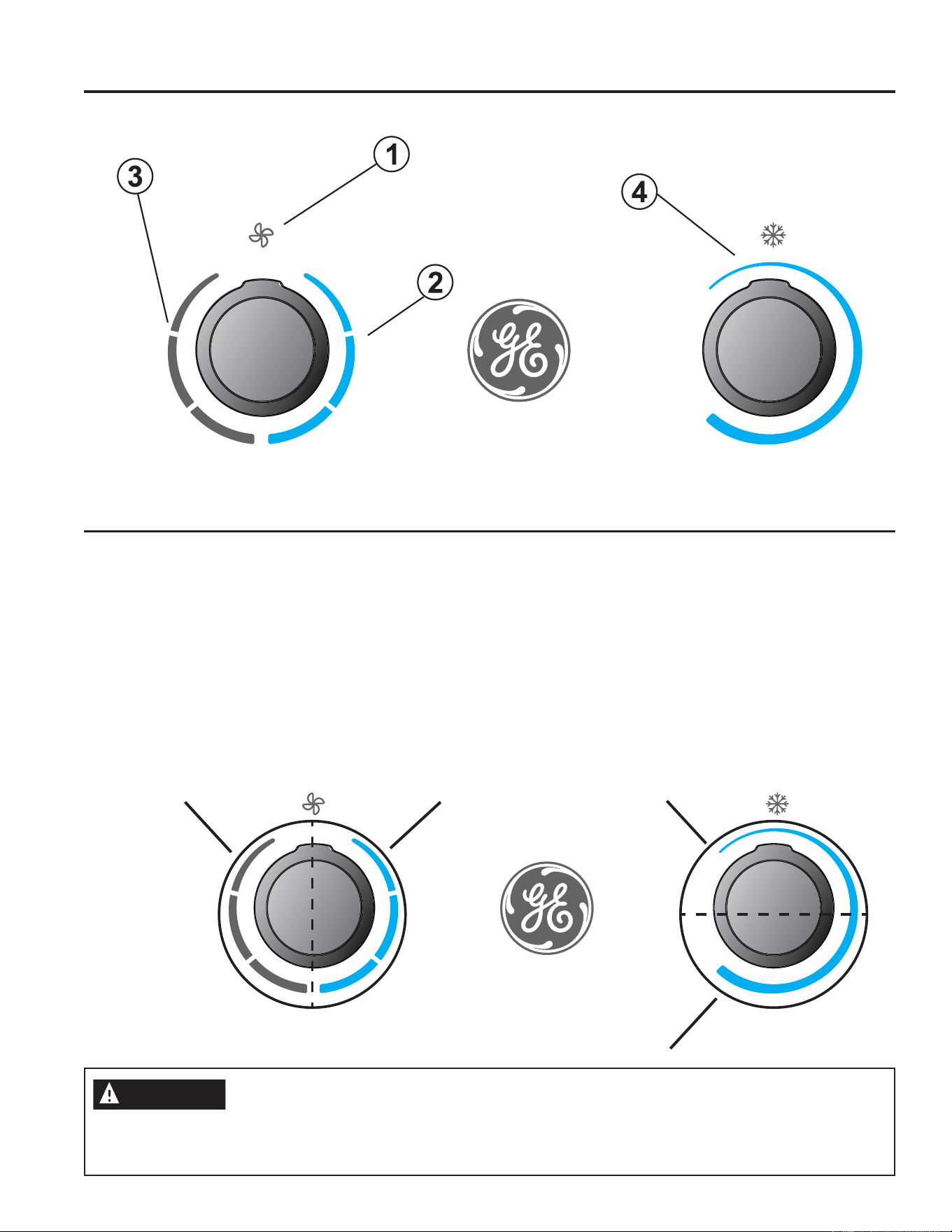
49-5000888 Rev. 5
Commandes
/HVIRQFWLRQVHWO¶DVSHFWSHXWYDULHU
Commandes du conditionneur
Commandes
1. Hors tension
/HFOLPDWLVHXUHVWpWHLQWGDQVFHWWHSRVLWLRQ
2. Modes de climatisation
Avec ces positions, le compresseur et les ventilateurs
fonctionnent pour fournir de l’air froid. Ces trois modes sont
pour les vitesses du ventilateur : faible, moyenne et élevée.
3. Modes de ventilation seulement
Avec ces modes, les ventilateurs fonctionneront pour faire
circuler l’air dans le véhicule récréatif. Ces trois modes sont
pour les vitesses du ventilateur : faible, moyenne et élevée.
4. Sélection de température
Ce bouton détermine le point de consigne de la température
GHODSLqFH7RXUQH]FHERXWRQSRXUDXJPHQWHURXGLPLQXHU
la température de l’air que le climatiseur devra fournir pour
la pièce.
ATTENTION
$ILQGHSUpYHQLUOHGpFOHQFKHPHQWGXGLVMRQFWHXUDWWHQGH]XQPLQLPXPGHPLQXWHVHQWUHODPLVHHQDUUrWHWODUHPLVHHQ
PDUFKHGXFRPSUHVVHXUFjGDWWHQGUHPLQXWHVDYDQWGHWRXUQHUOHFDGUDQGHODSRVLWLRQ$j%SXLVGHUHWRXUj$RX
GHODSRVLWLRQ$j%SXLVGHUHWRXUj$LOOXVWUpFLGHVVXV
Ma
x
Cool
With A
C
O
ff
F
an Speed
T
emperature
M
ax
C
ool
W
ith A
C
O
f
f
F
an S
p
eed
Tem
p
eratur
e
Position
2B
Position
2A
Position
1A
Position
1B
UTILISANT LE CONDITIONNEUR D’AIR
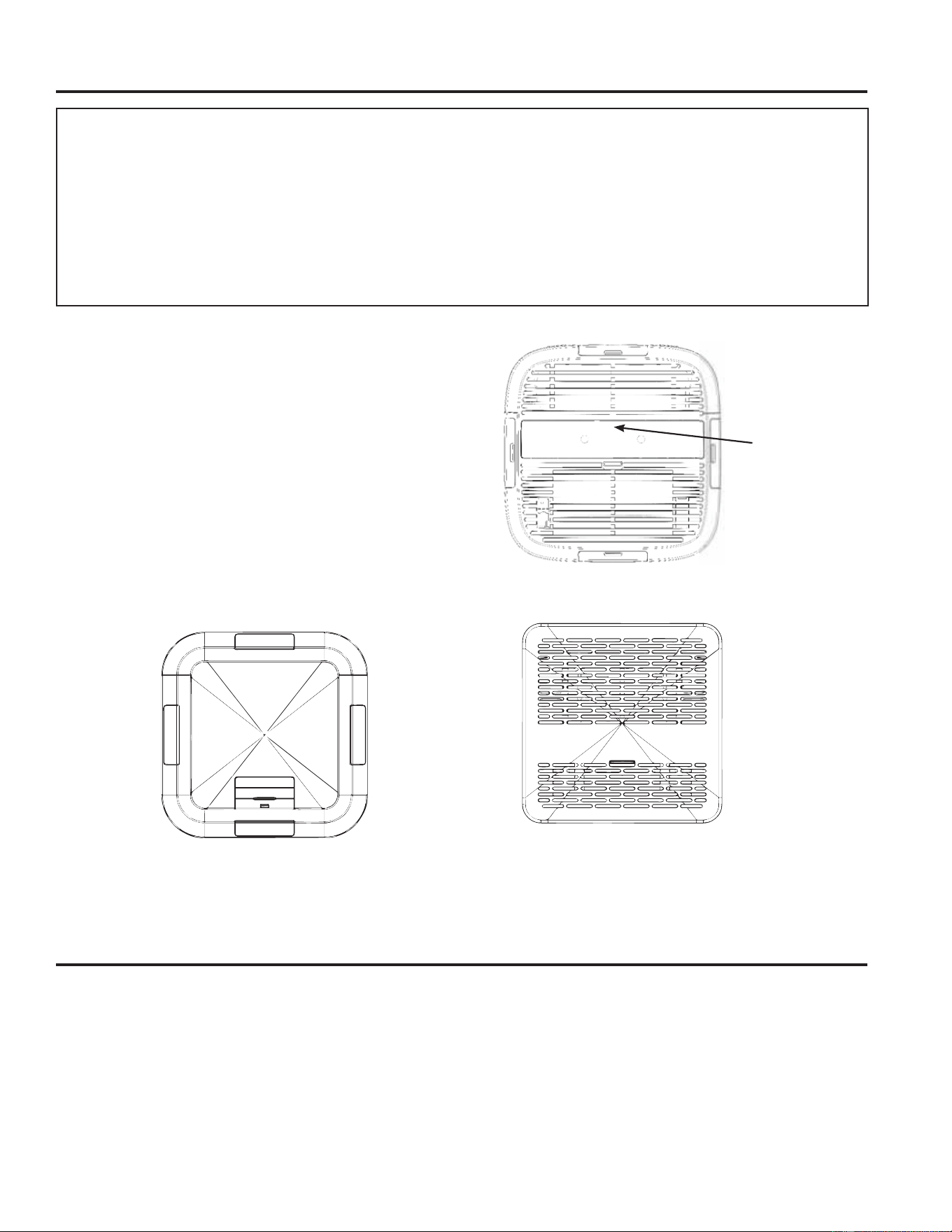
1949-5000888 Rev. 5
UTILISANT LE CONDITIONNEUR D’AIR
Utilisant le conditionneur d’air
IMPORTANTE:
/RUVTXHOHFOLPDWLVHXUHVWPLVjO¶DUUrWDWWHQGUHDXPRLQV
3 minutes avant de le remettre en marche. Ceci prévient la
surcharge du compresseur. Ce délai de 3 minutes s’applique
aussi pour le passage aux modes fraîcheur (Cool) et
ventilateur (Fan).
• Ne pas essayer de faire fonctionner le climatiseur en mode
fraîcheur (Cool) lorsque la température extérieure est
LQIpULHXUHj&)/HVHUSHQWLQG¶pYDSRUDWHXULQWHUQH
gèlera et le climatiseur ne fontionnera adéquatement.
$ILQGHSUpYHQLUOHGpFOHQFKHPHQWGXGLVMRQFWHXUORUV
du réglage du thermostat ou de la vitesse du ventilateur,
attendez 3 minutes entre les cycles du compresseur pour
DOORXHUVXIILVDPPHQWGHWHPSVjO¶pTXLOLEUDJHGHODSUHVVLRQ
du réfrigérant.
Orientation de l’air
Utilisez le levier ou ouvrir l’évent sur la face du panneau de
commandes.
Ouvrez ou fermez les quatre (4) sorties latérales pour régler la
circulation d’air provenant du climatiseur.
9XHGHIDFH
/HOHYLHUHVW
situé entre les
deux boutons.
Ces phénomènes sont normaux
/RUVTXHYRWUHFOLPDWLVHXUIRQFWLRQQHQRUPDOHPHQWYRXVSRXYH]HQWHQGUHGHVVRQVFRPPH
Ŷ/HVRQGHJRXWWHOHWWHVG¶HDXSHUFXWDQWOHFRQGHQVDWHXUFDXVDQWXQEUXLWG¶HDXSHUFXWDQWOHPpWDORXXQFOLTXHWLV/HV
JRXWWHOHWWHVG¶HDXDLGHQWjUHIURLGLUOHFRQGHQVDWHXU
Ŷ/HGpSODFHPHQWG¶DLUGXYHQWLODWHXU
Ŷ/HVFOLFVGHVF\FOHVGXWKHUPRVWDW
Ŷ
Un ronflement aigu ou un bruit de pulsation produit par les cycles d’arrêt et de démarrage du compresseur.
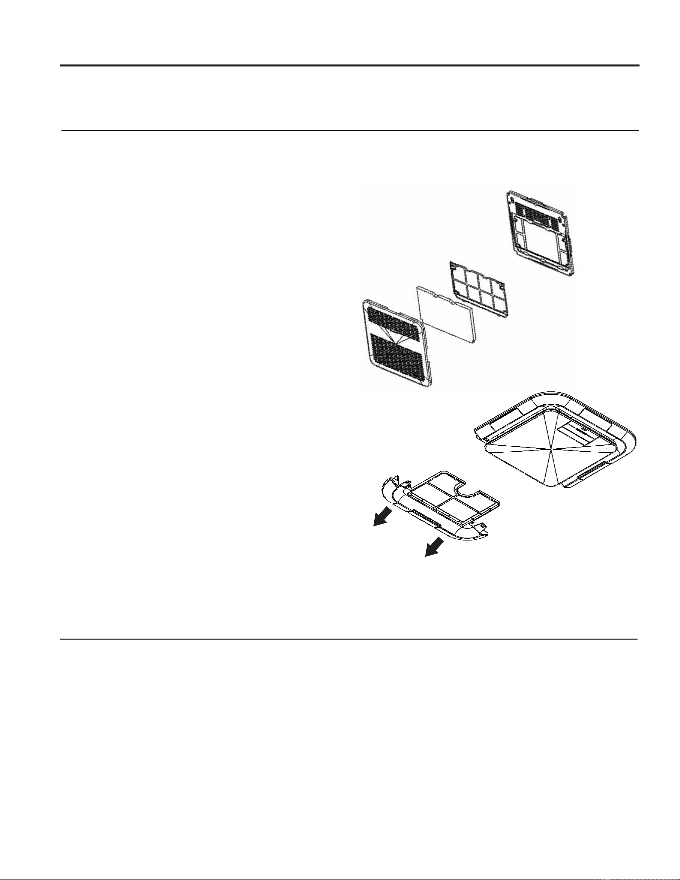
20 49-5000888 Rev. 5
Utilisant le conditionneur d’air
Panneau intérieur
Eteignez le climatiseur et débranchez le climatiseur avant
le nettoyage.
3RXUQHWWR\HUXWLOLVH]GHO¶HDXHWXQGpWHUJHQWGRX[
N’utilisez pas d’eau de Javel ou d’abrasifs.
Maintenance annuelle
9RWUHFOLPDWLVHXUDEHVRLQG¶XQHQWUHWLHQDQQXHOSRXUDVVXUHU
des performances optimales et constantes tout au long de
l’année.
Appelez votre revendeur agréé local pour planifier un bilan de
VDQWpDQQXHO/HVIUDLVG¶XQHLQVSHFWLRQDQQXHOOHVRQWjYRWUH
charge.
Filtre à air
/HILOWUHjDLUGRLWrWUHYpULILpWRXWHVOHVVHPDLQHVHWQHWWR\p
le cas échéant.
NE PAS faire fonctionner le climatiseur sans filtre, car la saleté
et les peluches l’encrassent et réduisent les performances.
Nettoyage du filtre à air
eWHLJQH]OHFOLPDWLVHXU
5HWLUH]OHFRXYHUFOHGXILOWUHjDLUVHORQOHVLOOXVWUDWLRQV
suivantes pour accéder au filtre.
8WLOLVH]XQDVSLUDWHXUSRXUQHWWR\HUOHILOWUHjDLU6LOHILOWUHj
DLUHVWWUqVVDOHQHWWR\H]OHjO¶HDXWLqGHDYHFXQGpWHUJHQW
GRX[1HODYH]SDVOHILOWUHjDLUDXODYHYDLVVHOOHHWQ¶XWLOLVH]
aucun produit de nettoyage chimique. Séchez complètement
OHILOWUHjDLUDYDQWGHOHUHPSODFHUSRXUDVVXUHUXQH
efficacité maximale.
5HPRQWH]OHILOWUHjDLUVXUOHJULO
5pDVVHPEOH]VRLJQHXVHPHQWOHJULOHWOHILOWUHVXUOH
panneau principal.
6. Allumer le climatiseur.
REMARQUE : /HVDVVHPEODJHV535(1HW535('XWLOLVHQW
XQILOWUH0(59TXLGRLWrWUHUpJXOLqUHPHQWYpULILpHWHQWUHWHQX
pour être exempt de débris.
3RXVVH]OHVGHX[ODQJXHWWHVYHUVOHORJR*(SRXUGpJDJHUOH
couvercle.
UTILISANT LE CONDITIONNEUR D’AIR / ENTRETIEN ET NETTOYAGE
RPRED
RPREN
2149-5000888 Rev. 5
Conseils de dépannage«DYDQWG¶DSSHOHUOHVHUYLFH
eFRQRPLVH]WHPSVHWDUJHQW([DPLQH]G¶DERUGOHVWDEOHDX[VXLYDQWVXQDSSHOGHVHUYLFHVHUDSHXWrWUHLQXWLOH
Problème Cause possible Solution
Le climatiseur ne
fonctionne pas.
Un fusible est grille ou le disjoncteur est
déclenché.
5HPSODFH]OHIXVLEOHRXHQFOHQFKH]jQRXYHDXOHGLVMRQFWHXU6L
le problème persiste, appelez un électricien.Consultez le chapitre
³([LJHQFHVpOHFWULTXHV´
Le réglage du mode est en position OFF.
$SSX\H]VXU32:(5RXUpJOH]OHPRGHVXUXQSDUDPqWUHDFWLI
Panne de courant locale. Attendez que la panne soit rétablie.
Le climatiseur
brûle les fusibles
ou déclenche les
disjoncteurs.
Trop d’appareils sont utilisés sur le même
circuit.
Débranchez ou déplacez les appareils partageant le même circuit.
Le fusible temporisé ou le disjoncteur
n’est pas adapté à l’utilisation.
5HPSODFH]SDUXQIXVLEOHWHPSRULVpRXXQGLVMRQFWHXUDGDSWpj
O¶XWLOLVDWLRQ&RQVXOWH]OHFKDSLWUH³([LJHQFHVpOHFWULTXHV´
Vous avez éteint le climatiseur et n’avez
pas attendu assez longtemps avant de le
redémarrer.
Attendez au moins trois (3) minutes après avoir éteint le climatiseur
avant de le remettre en marche.
Le climatiseur
semble trop
fonctionner.
Le climatiseur actuel remplace un vieux
modèle.
/¶XWLOLVDWLRQGHFRPSRVDQWVSOXVHIILFDFHVSHXWFDXVHUXQ
IRQFWLRQQHPHQWSOXVORQJGXFOLPDWLVHXUFRPSDUDWLYHPHQWjXQYLHX[
modèle, mais la consommation énergétique sera moindre.
/HVQRXYHDX[FOLPDWLVHXUVQHSURGXLVHQWSOXVGH³FRXSGHYHQW´
G¶DLUIURLGHWYRXVrWHVSHXWrWUHKDELWXpjGHO¶DLUSOXVIURLGGHV
vieux modèles, mais ceci n’est pas un indice de capacité ou
d’efficacité de refroidissement moindre.
Le climatiseur fonctionne dans une pièce
occupée par plusieurs personnes ou des
appareils de chauffage fonctionnent dans
la pièce.
Utilisez une hotte pendant la cuisson ou un ventilateur de salle de
bain pendant les douches et essayez de ne pas utiliser d’appareils
produisant de la chaleur pendant les périodes les plus chaudes de
ODMRXUQpH8QFOLPDWLVHXUSOXVSXLVVDQWSHXWrWUHQpFHVVDLUHHQ
IRQFWLRQGHODGLPHQVLRQGHODSLqFHjUHIURLGLU
Les cycles de mise
en marche et d’arrêt
du climatiseur sont
trop fréquents et
ne climatise pas la
pièce en mode de
refroidissement.
La capacité du climatiseur est insuffisante
pour votre véhicule récréatif.
9pULILH]OHVFDSDFLWpVGHUHIURLGLVVHPHQWGXFOLPDWLVHXUGHYRWUH
véhicule récréatif.
Le filtre est sale ou obstrué par des débris.
Nettoyez ou remplacez le filtre.
Une chaleur ou de la moisissure
excessives (ouverture de contenants de
cuisson, douches, etc.) dans la pièce.
Utilisez un ventilateur pour évacuer la chaleur et l’humidité de
la pièce. Essayez de ne pas utiliser d’appareils produisant de la
FKDOHXUSHQGDQWOHVSpULRGHVOHVSOXVFKDXGHVGHODMRXUQpH
Les évents sont fermés. Assurez-vous que les évents sont ouverts.
Les persiennes ou les conduits sont
fermés.
Ne tentez pas de faire fonctionner votre climatiseur en mode de
UHIURLGLVVHPHQWORUVTXHODWHPSpUDWXUHH[WpULHXUHHVWLQIpULHXUHj
°C (65 °F).
La température extérieure est inférieure à
15 ° C (60 ° F).
Allouez une période plus longue de refroidissement au climatiseur
lorsque la pièce est très chaude.
Des fenêtres ou des portes menant à
l’extérieur sont ouvertes.
Fermez toutes les portes et toutes les fenêtres.
La commande de température n’est pas
assez basse.
$MXVWH]ODFRPPDQGHGHWHPSpUDWXUHHWGHWHPSV7(037,0(
jXQUpJODJHSOXVIURLGHQDSSX\DQWVXUOHERXWRQPRLQVSRXU
GLPLQXHUODWHPSpUDWXUH5pJOH]ODFRPPDQGHGHYLWHVVHGX
YHQWLODWHXUjO¶LQWHQVLWpODSOXVpOHYpH
De l’eau s’égoutte
de l’appareil à
l’intérieur de la
pièce
Le serpentin intérieur est peut-être gelé. Faites dégeler le serpentin en faisant fonctionner seulement le
ventilateur.
Le joint d’étanchéité de montage du
climatiseur ne permet pas l’étanchéité
avec le toit.
9pULILH]OHVERXORQVGHIL[DWLRQHWVHUUH]OHVjLQOEVL
nécessaire.
Le climatiseur
grille les fusibles
ou déclenche le
disjoncteur
Le serpentin du condenseur ou le
ventilateur du condenseur est bloqué ou
obstrué
5HWLUH]WRXWHPDWLqUHEORTXDQWHGXVHUSHQWLQGXFRQGHQVHXURXGX
ventilateur du condenseur
CONSEILS DE DÉPANNAGE

22 49-5000888 Rev. 5
SCHÉMAS DE PRINCIPE
Schémas de principe
AC WIRING DIAGRAM
NOTE
3mm
3mm
WIRE COLOR
CONNECTOR
From
①
to
ĺ
,and to
,one to one.
B
1 3
Y/G
W
1
2
3
4
R
OR
①②③
1
2
3
④
GR
Y
0011526311A
3
1
Y/G:YELLOW/GREEN
B :BLACK
W :WHITE
R :RED
BL:BLUE
Y :YELLOW
OR:ORANGE
BR:BROWN
GR:GREY
CAP.
~
R
C
M
S
COMP.
R
W
W
B
B
B
3
1
W
W
D
W
W
ID FAN
MOTOR
L
M
H
~
M
N
Y/G
CAP.
③①
W
OR
Y
R
BR BL
N
M
~
Y/G
OD FAN
MOTOR
BRBL
GR
W
B
④
GR
C
1
2
GR
W
CAP.
1
2
1
2
W
Y/G
W
B
OPTIONAL
CONDENSATE
PUMP
②
120mm
80mm
3mm
3mm
HP WIRING DIAGRAM
NOTE
WIRE COLOR
CONNECTOR
From
①
to
ĺ
,and to
,one to one.
3
1
B
1 3
Y/G
W
1
2
3
4
R
BL
OR
①
②
③
1
2
3
④
GR
0011526291A
Y/G:YELLOW/GREEN
B :BLACK
W :WHITE
R :RED
BL:BLUE
Y :YELLOW
OR:ORANGE
BR:BROWN
GR:GREY
CAP.
~
R
C
M
S
COMP.
R
W
W
B
B
B
3
1
W
W
D
W
W
ID FAN
MOTOR
L
M
H
~
M
N
Y/G
CAP.
③①
W
OR
Y
R
BR BL
N
M
~
Y/G
OD FAN
MOTOR
BRBL
GR
W
B
④
GR
C
1
2
4-WAY
BL
BL
②
BL
GR
W
CAP.
1
2
1
2
W
Y/G
W
B
OPTIONAL
CONDENSATE
PUMP
120mm
80mm
2349-5000888 Rev. 5
GARANTIE LIMITÉE
Garantie limitée du conditionneur d’air
Ŷ7RXWHYLVLWHjYRWUHGRPLFLOHSRXUYRXVH[SOLTXHUOH
fonctionnement de l’appareil.
Ŷ8QHLQVWDOODWLRQXQHOLYUDLVRQRXXQHQWUHWLHQLQDGpTXDWV
3RXUWRXWSUREOqPHG¶LQVWDOODWLRQRXVLOHFOLPDWLVDWHXU
n’assure pas une climatisation adéquate, communiquez
DYHFYRWUHGpWDLOODQWRXYRWUHLQVWDOODWHXU9RXVDYH]OD
responsabilité de fournir les installations appropriées pour les
raccordements électriques.
Ŷ8QHGpIHFWXRVLWpDWWULEXDEOHjXQHPRGLILFDWLRQGXSURGXLW
une utilisation déraisonnable ou un entretien inadéquat ou
négligent.
Ŷ'DQVOHVpWDEOLVVHPHQWVFRPPHUFLDX[ODPDLQG¶°XYUH
QpFHVVDLUHSRXUDPHQHUO¶DSSDUHLOjXQHQGURLWRLOSRXUUD
être accessible aux fins de réparation par un technicien.
Ŷ/HUHPSODFHPHQWGHVIXVLEOHVRXOHUpHQFOHQFKHPHQWGHV
GLVMRQFWHXUV
Ŷ8QHGpIHFWXRVLWpDWWULEXDEOHjODFRUURVLRQVXUOHVPRGqOHV
qui ne sont pas protégés contre la corrosion.
Ŷ/HVGRPPDJHVDXSURGXLWDWWULEXDEOHVjXQHDOLPHQWDWLRQ
électrique inadéquate, un accident, un incendie, une
LQRQGDWLRQRXXQFDVGHIRUFHPDMHXUH
Ŷ7RXWGRPPDJHGLUHFWRXLQGLUHFWjODSURSULpWpFDXVpSDUXQH
éventuelle défectuosité de ce climatiseur.
Ŷ/HVGRPPDJHVVXUYHQXVDSUqVODOLYUDLVRQ
Ce qui n’est pas couvert par GE Appliances :
&HWWHJDUDQWLHOLPLWpHHVWRIIHUWHjO¶DFKHWHXULQLWLDOHWjWRXWSURSULpWDLUHVXEVpTXHQWG¶XQSURGXLWDFKHWpHQYXHG¶XQHXWLOLVDWLRQ
DX[eWDWV8QLVHWDX&DQDGD6LOHSURGXLWHVWLQVWDOOpGDQVXQHUpJLRQQRQGHVVHUYLHSDUXQUpSDUDWHXUDXWRULVp*($SSOLDQFHV
YRXVSRXUULH]rWUHWHQXG¶DVVXPHUGHVIUDLVGHGpSODFHPHQWRXG¶DSSRUWHUOHSURGXLWjXQFHQWUHGHUpSDUDWLRQDXWRULVp*(
$SSOLDQFHV(Q$ODVNDODJDUDQWLHOLPLWpHQHFRXYUHSDVOHVIUDLVG¶H[SpGLWLRQHWOHVDSSHOVGHVHUYLFHjYRWUHGRPLFLOH
'DQVFHUWDLQVeWDWVRXSURYLQFHVLOHVWLQWHUGLWG¶H[FOXUHRXGHOLPLWHUOHVGRPPDJHVGLUHFWVRXLQGLUHFWV/DSUpVHQWHJDUDQWLH
OLPLWpHYRXVFRQIqUHGHVGURLWVMXULGLTXHVVSpFLILTXHV9RXVSRXYH]EpQpILFLHUG¶DXWUHVGURLWVTXLYDULHQWG¶XQHSURYLQFHRX
G¶XQeWDWjO¶DXWUH3RXUFRQQDvWUHOHVGURLWVGRQWYRXVEpQpILFLH]GDQVYRWUHUpJLRQFRPPXQLTXH]DYHFGHVUHODWLRQVDYHFOHV
FRQVRPPDWHXUVGHYRWUHUpJLRQRXHQFRUHOH3URFXUHXUJpQpUDOGHYRWUHeWDW
Garant : GE Appliances, a Haier company
Louisville, KY 40225
7RXWHUpSDUDWLRQVRXVJDUDQWLHGRLWrWUHUpDOLVpHSDUQRV&HQWUHVGHVHUYLFHHQXVLQHRXXQWHFKQLFLHQ&XVWRPHU&DUH
®
DXWRULVp3RXUSUpYRLUXQHUpSDUDWLRQFRQVXOWH]QRWUHVLWHelectromenagersge.car/soutien/demande-de-service ou appelez
OH9HXLOOH]DYRLUYRWUHQXPpURGHVpULHHWYRWUHQXPpURGHPRGqOHjSRUWpHGHPDLQORUVTXHYRXVDSSHOH]SRXU
obtenir un service.
EXCLUSION DE GARANTIES IMPLICITES - Votre seul et unique recours consiste dans la réparation du produit
selon les dispositions de cette Garantie limitée. Toutes les garanties implicites, incluant les garanties de qualité
marchande et de convenance, sont limitées à deux ans ou à la période la plus courte autorisée par la loi.
Pendant la période de
garantie de :
GE Appliances remplacera :
Deux ans
A compter de la date d’achat
initial
Toute pièce du climatiseur qui se révèle défectueuse en raison d’un vice de matières ou
de fabrication. Au cours de cette garantie limitée de deux ans, GE Appliances couvrira
JUDWXLWHPHQWOHVIUDLVGHPDLQG¶°XYUHHWOHVIUDLVGHVHUYLFHDVVRFLpVSRXUUHPSODFHUOD
pièce défectueuse.
$JUDIH]YRWUHIDFWXUHLFL3RXUEpQp¿FLHUGXVHUYLFHGHUpSDUDWLRQ
sous garantie, une preuve de la date d’achat initial est nécessaire.

24 49-5000888 Rev. 5
Soutien au consommateur
SOUTIEN AU CONSOMMATEUR
Site Web de GE Appliances
9RXVDYH]XQHTXHVWLRQRXYRXVDYH]EHVRLQG¶DLGHSRXUYRWUHDSSDUHLOpOHFWURPpQDJHU"9LVLWH]OHVLWH:HEGH*($SSOLDQFHV
KHXUHVSDUMRXUWRXVOHVMRXUVGHO¶DQQpH9RXVSRXYH]DXVVL\WURXYHUG¶DXWUHVIRUPLGDEOHVSURGXLWV*($SSOLDQFHVHWWLUHU
DYDQWDJHGHWRXVQRVVHUYLFHVG¶DVVLVWDQFHHQOLJQH$X[eWDWV8QLVGEAppliances.com
Enregistrez votre électroménager
(QUHJLVWUH]YRWUHQRXYHODSSDUHLOHQOLJQHDXPRPHQWTXLYRXVFRQYLHQWOHPLHX[/¶HQUHJLVWUHPHQWGHYRWUHSURGXLWGDQVOHV
délais prescrits permet une meilleure communication et un service rapide, selon les modalités de votre garantie, si besoin est.
9RXVSRXYH]pJDOHPHQWHQYR\HUSDUFRXUULHUODFDUWHG¶HQUHJLVWUHPHQWSUpLPSULPpHTXLVHWURXYHGDQVO¶HPEDOODJHGHYRWUH
appareil.
$X[eWDWV8QLVGEAppliances.com/register
Service de réparation
$X[eWDWV8QLVGEAppliances.com/service RXFRPSRVH]OHGXUDQWOHVKHXUHVQRUPDOHVGHEXUHDX
Prolongation de garantie
3URFXUH]YRXVXQHSURORQJDWLRQGHJDUDQWLH*($SSOLDQFHVHWLQIRUPH]YRXVGHVUDEDLVVSpFLDX[HQYLJXHXUSHQGDQWODGXUpH
GHYRWUHJDUDQWLH9RXVSRXYH]YRXVODSURFXUHUHQOLJQHHQWRXWWHPSV/HVVHUYLFHV*($SSOLDQFHVVHURQWWRXMRXUVGLVSRQLEOHV
DSUqVO¶H[SLUDWLRQGHODJDUDQWLH$X[eWDWV8QLV
GEAppliances.com/extended-warrantyRXFRPSRVH]OHGXUDQWOHVKHXUHVQRUPDOHVGHEXUHDX
Pièces et accessoires
/HVSHUVRQQHVD\DQWOHVFRPSpWHQFHVUHTXLVHVSRXUUpSDUHUHOOHVPrPHVOHXUVDSSDUHLOVSHXYHQWUHFHYRLUGLUHFWHPHQWjOD
PDLVRQGHVSLqFHVRXDFFHVVRLUHVOHVFDUWHV9,6$0DVWHU&DUGHW'LVFRYHUVRQWDFFHSWpHV&RPPDQGH]HQOLJQHKHXUHV
SDUMRXU
$X[eWDWV8QLVGEApplianceparts.comRXSDUWpOpSKRQHDXGXUDQWOHVKHXUHVQRUPDOHVGHEXUHDX
Les instructions contenues dans le présent manuel comportent des procédures que tout utilisateur peut effectuer. Les
autres types de réparation doivent généralement être confiés à un technicien qualifié. Usez de prudence : une réparation
ou un entretien mal effectués peuvent rendre l’utilisation de l’appareil dangereuse.
Communiquez avec nous
Si vous n’êtes pas satisfait du service après-vente de GE Appliances, communiquez avec nous depuis notre site Web en fournissant
WRXVOHVGpWDLOVGRQWYRWUHQXPpURGHWpOpSKRQHRXpFULYH]j
$X[eWDWV8QLV*HQHUDO0DQDJHU&XVWRPHU5HODWLRQV_*($SSOLDQFHV$SSOLDQFH3DUN_/RXLVYLOOH.<
GEAppliances.com/contact

ACCONDICIONADORES DE AIRE
PARA SALA
GE es una marca registrada de General Electric Company. Fabricado bajo licencia de marca.
MANUAL DEL
PROPIETARIO
Unidades de Techo:
Altura Estándar
GRCS13XHH_
GRHS13XHH_
GRCS13XAH_
GRHS13XAH_
GRCS15XAH_
GRHS15XAH_
Perfil Bajo
PLCS13XHH_
PLHS13XHH_
PLCS13XAH_
PLHS13XAH_
PLCS15XAH_
PLHS15XAH_
Ensambles de Interior:
RPRED_ _
RPREN_ _
RGRED_ _
RGREN_ _
RGRMN_ _
ESPAÑOL
Escriba los números de modelo y de serie
aquí:
Nº de Modelo ____________
Nº de Serie ______________
Estos números se encuentran en una
etiqueta al costado del acondicionador
de aire.
INFORMACIÓN
DE SEGURIDAD ...................3
INSTRUCCIONES DE
INSTALACIÓN
Antes de comenzar ....................4
Herramientas Que
Necesitará. . . . . . . . . . . . . . . . . . .........4
RGRMN_ _ Lista de partes ..............5
RGREN_ _ Lista de partes ...............6
RGRED_ _ Lista de partes ...............7
RPREN_ _ Lista de partes ...............8
RPRED_ _ Lista de partes ...............9
Requisitos para instalaciones ...........10
Requisitos y preparación del techo .....12
Requisitos Eléctricos ..................12
Colocación de la unidad en el techo .....12
Instalación del control mecánico ........14
Inst. Del control eléctrico ..............15
USO DEL ACONDICIONADOR
DE AIRE
Controles ............................18
Dirección del Aire. . . . . . . . . . . . . . . . . . ..19
Sonidos de operación normales ........19
CUIDADO Y LIMPIEZA
Parrilla y Caja ....................... 20
Filtro de Aire. . . . . . . . . . . . . . . . . . ..... 20
Mantenimiento anual ................. 20
SOLUCIÓN DE PROBLEMAS ...21
DIAGRAMAS
ESQUEMÁTICOS .................22
GARANTÍA LIMITADA ..........23
SOPORTE AL CLIENTE ......... 24
49-5000888 Rev. 5 05-25

2 49-5000888 Rev. 5
GRACIAS POR HACER QUE GE APPLIANCES SEA PARTE DE SU HOGAR.
Ya sea que haya crecido usando GE Appliances, o que ésta es su primera vez, nos complace
tenerlo en la familia.
Sentimos orgullo por el nivel de arte, innovación y diseño de cada uno de los electrodomésticos de
GE Appliances, y creemos que usted también. Entre otras cosas, el registro de su electrodoméstico
asegura que podamos entregarle información importante del producto y detalles de la garantía
cuando los necesite.
Registre su electrodoméstico GE ahora a través de Internet. Sitios Web y números telefónicos útiles
están disponibles en la sección de Soporte para el Consumidor de este Manual del Propietario.
49-5000888 Rev. 5 3
INFORMACIÓN IMPORTANTE DE SEGURIDAD
LEA TODAS LAS INSTRUCCIONES ANTES DE USAR
INFORMACIÓN DE SEGURIDAD
Para su seguridad, siga las instrucciones de este manual a fin de minimizar riesgos
de incendio, descargas eléctricas o lesiones personales.
Ŷ8VHHVWHHOHFWURGRPpVWLFRVyORSDUDVXSURSyVLWRRULJLQDO
como se describe en el Manual del Propietario.
Ŷ(VWHDFRQGLFLRQDGRUGHDLUHGHEHUiVHULQVWDODGRGHIRUPD
apropiada de acuerdo con las Instrucciones de Instalación
antes de su uso.
Ŷ5HHPSODFHGHLQPHGLDWRWRGRVORVFDEOHVGHFRUULHQWH
pelados o con cualquier tipo de daño.
Ŷ$SDJXHODXQLGDG\GHVFRQHFWHWRGDODFRUULHQWHGHO
vehículo antes de realizar la limpieza y el servicio técnico.
Ŷ$ILQGHHYLWDUULHVJRVGHOHVLRQHVRGDxRVVREUHOD
propiedad, el servicio técnico del acondicionador de aire
sólo deberá ser realizado por un técnico calificado, quien
deberá poseer un certificado actualizado y validado por
una autoridad de evaluación industrial acreditada, la cual
autorice su competencia para manejar refrigerantes de
forma segura, de acuerdo con una especificación de
evaluación industrial reconocida.
Ŷ3DUDVXVHJXULGDGQRDFXPXOHQLXVHPDWHULDOHV
combustibles, gasolina u otros vapores o líquidos
inflamables cerca de éste u otro electrodoméstico.
Ŷ7RGRVORVDFRQGLFLRQDGRUHVGHDLUHFRQWLHQHQUHIULJHUDQWHV
los cuales de acuerdo con la ley federal deben ser retirados
antes de deshacerse del producto. Si se deshará de un
producto antiguo con refrigerantes, consulte a la compañía
a cargo sobre cómo deshacerse del mismo.
Ŷ(VWRVVLVWHPDVGHDFRQGLFLRQDGRUHVGHDLUH5UHTXLHUHQ
que los contratistas y técnicos utilicen herramientas,
equipamientos y estándares de seguridad aprobados
para el uso con este refrigerante. NO use equipamiento
certificado sólo para otros refrigerantes.
Ŷ(VWHHOHFWURGRPpVWLFRQRGHEHUiVHUXVDGRSRUSHUVRQDV
(incluyendo niños) con capacidades físicas, sensoriales
o mentales reducidas o con falta de experiencia y
conocimiento, a menos que cuenten con supervisión o
instrucción con relación al uso de este electrodoméstico por
parte de una persona responsable de su seguridad.
ADVERTENCIA
Para obtener información sobre el reciclaje de electrodomésticos, visite GEAppliances.com/recycling
LEA Y GUARDE ESTAS INSTRUCCIONES
Ŷ$ILQGHDFHOHUDUHOSURFHVRGHGHVFRQJHODFLyQRSDUD
limpiar, no use ningún método que no sea el recomendado
por el fabricante.
Ŷ(VWHHOHFWURGRPpVWLFRGHEHUiVHUJXDUGDGRHQXQDVDOD
donde no haya fuentes de encendido continuas (por ejemplo:
llamas abiertas, un electrodoméstico que funcione a gas o
un calefactor que funcione a electricidad).
Ŷ1RSHUIRUHQLTXHPHHOWXERUHIULJHUDQWH7HQJDSUHVHQWH
que los refrigerantes no deben tener olor.
Ŷ0DQWHQJDODVDEHUWXUDVGHODYHQWLODFLyQOLEUHVGH
obstrucciones.
Ŷ$OPRYHULQVWDODU\RSHUDUHOHOHFWURGRPpVWLFRVHGHEHUi
tener cuidado para evitar dañar la tubería del refrigerante.
Ŷ1RUHDOLFHSHUIRUDFLRQHVHQODXQLGDG
Ŷ(OPDQWHQLPLHQWRODOLPSLH]D\HOVHUYLFLRWpFQLFRVyOR
deberán ser realizados por técnicos adecuadamente
entrenados y calificados en el uso de refrigerantes
inflamables.
Ŷ*($SSOLDQFHVQREULQGDQLQJ~QVHUYLFLRWpFQLFRGH
componentes del sistema sellado (es decir: piezas que
contengan refrigerante) del acondicionador de aire.
Ŷ'HVFDUWHHOHOHFWURGRPpVWLFRGHDFXHUGRFRQODV
Regulaciones Federales y Locales. Los refrigerantes
inflamables requieren procedimientos de descarte
específicos. A fin de descartar su acondicionador de aire
de forma ambientalmente segura, comuníquese con las
autoridades locales.
Riesgo de Incendio o Explosión. Esta unidad contiene refrigerante
inflamable. Se deben seguir las precauciones adicionales de seguridad.
ADVERTENCIA
A2L
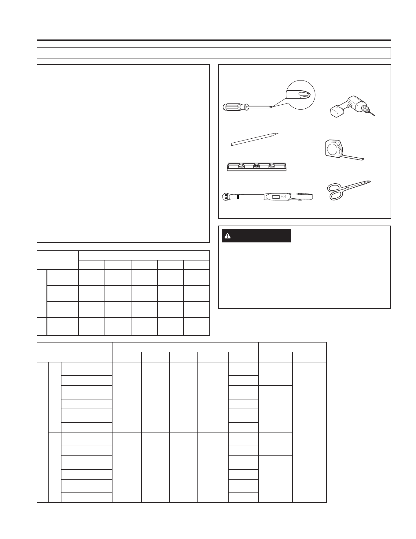
4 49-5000888 Rev. 5
Conocimiento General
ANTES DE INICIAR
Lea estas instrucciones completa y cuidadosamente.
• Guarde estas instrucciones para uso del inspector local.
• Observe todos los códigos y órdenes de ley.
• Nota al instalador – Asegúrese de dejar estas
instrucciones con el consumidor.
• Nota al consumidor – Conserve estas instrucciones para
referencia futura..
• Nivel de destreza – La instalación de este aparato
requiere de destrezas mecánicas básicas.
• Tiempo de ejecución – Aprox. 1 hora
• Recomendamos dos personas para la instalación de este
producto.
• La instalación apropiada es la responsabilidad del
instalador.
• La falla del producto debido a una instalación inadecuada
no está cubierta por la garantía.
&XDQGRLQVWDOHHVWHDFRQGLFLRQDGRUGHDLUH'(%(XVDU
todas las piezas suministradas y usar procedimientos
adecuados de instalación.
¿Preguntas? Llame 800.GE.CARES (800.432.2737) o visite nuestra página en la red en: GEAppliances.com
GUIA DE INSTALACIÓN
PRECAUCIÓN
7HQJDFXLGDGRFRQORVERUGHVDILODGRV\DTXHSXHGHQ
causar lesiones. Al levantar el aire acondicionado, use 2
personas para levantarlo.
El cableado eléctrico puede estar presente entre el
techo y el techo. Asegúrese de que la alimentación esté
desconectada de la red eléctrica y la batería. Asegúrese
GHTXHHOVXPLQLVWURGHJDVHVWpFHUUDGR'HORFRQWUDULR
puede sufrir lesiones o la muerte.
HERRAMIENTAS NECESARIAS
'HVWRUQLOODGRU3KLOOLSV
Regla o cinta de medición
Lápiz
Nivel
7LMHUDVRFXFKLOOR
/ODYH'LQDPRPpWULFDSXOJDGDV
libras)
7DODGUR\EURFDGH´
Asambleas interiores
RPRED RPREN RGRED RGREN RGRMN
Elec. Control
RGREC1A
X
RGREC2A
X
RGREC3A
X
Tstat
RGRWT
X
Unités Intérieures Tamaño del interruptor
RPRED RPREN RGRED RGREN RGRMN MCA MOP
Unidades de Interior
Altura estándar
GRCS13XHH_
15A
20A
GRHS13XHH_
X
GRCS13XAH_
20A
GRHS13XAH_
X
GRCS15XAH_
GRHS15XAH_
X
Perfil bajo
PLCS13XHH_
15A
PLHS13XHH_
X
PLCS13XAH_
20A
PLHS13XAH_
X
PLCS15XAH_
PLHS15XAH_
X
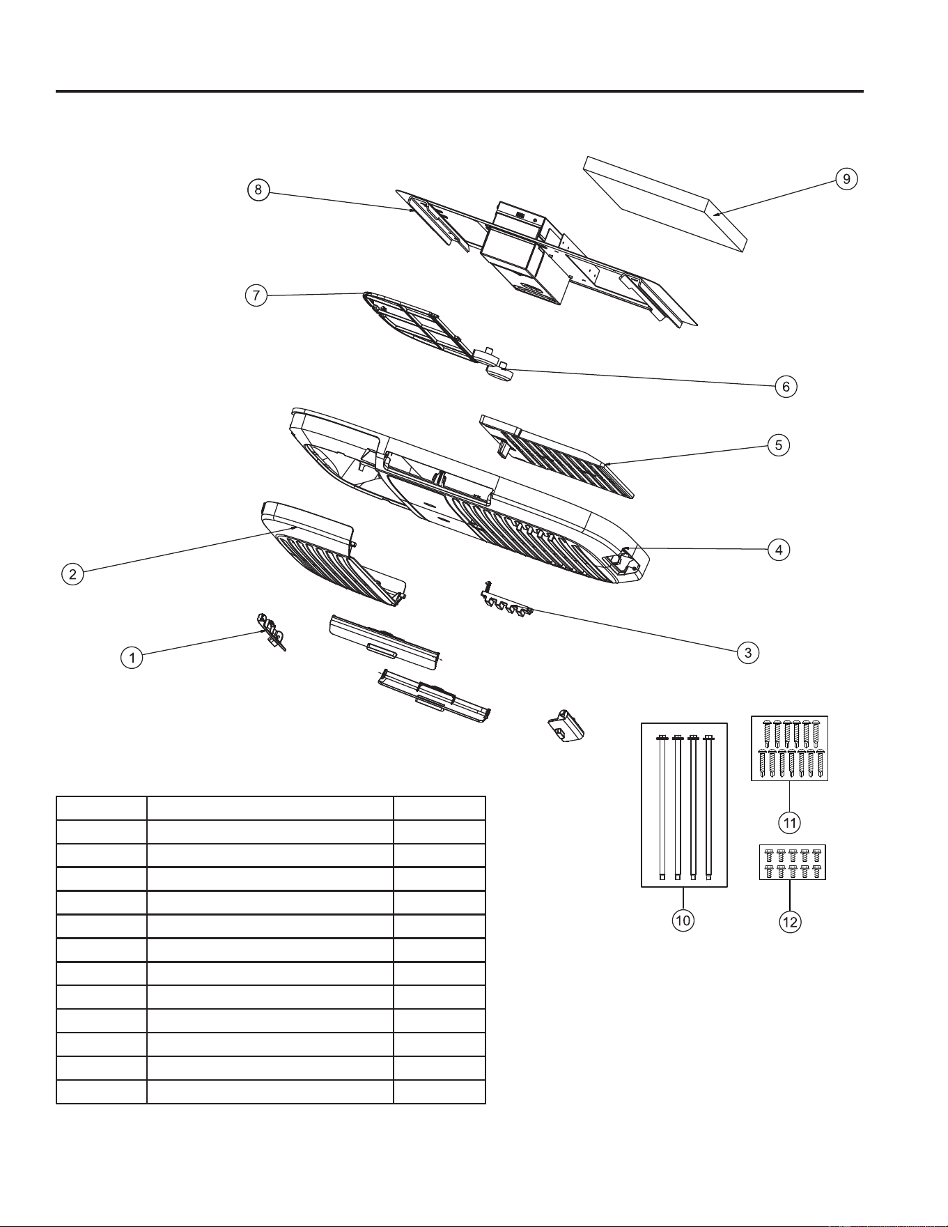
49-5000888 Rev. 5 5
GUIA DE INSTALACIÓN
Vista Expandida
RGRMN
8
Número Nombre de parte Cantidad
5HMLOODGH'HVFDUJDGH$LUH 4
2 7DSDGHO)LOWUR
3 7DSDGHO7RUQLOOR 2
4 Panel de techo
5 *XtDGH'HVFDUJD'LUHFWDGH$LUH
%RWyQ 2
7 Filtro
Plantilla de montaje
9 'HIOHFWRUGHGLYLVLyQDpUHD
3HUQRVGHPRQWDMH0 4
7RUQLOORVSDUDPDGHUD
7RUQLOORVGHFKDSD
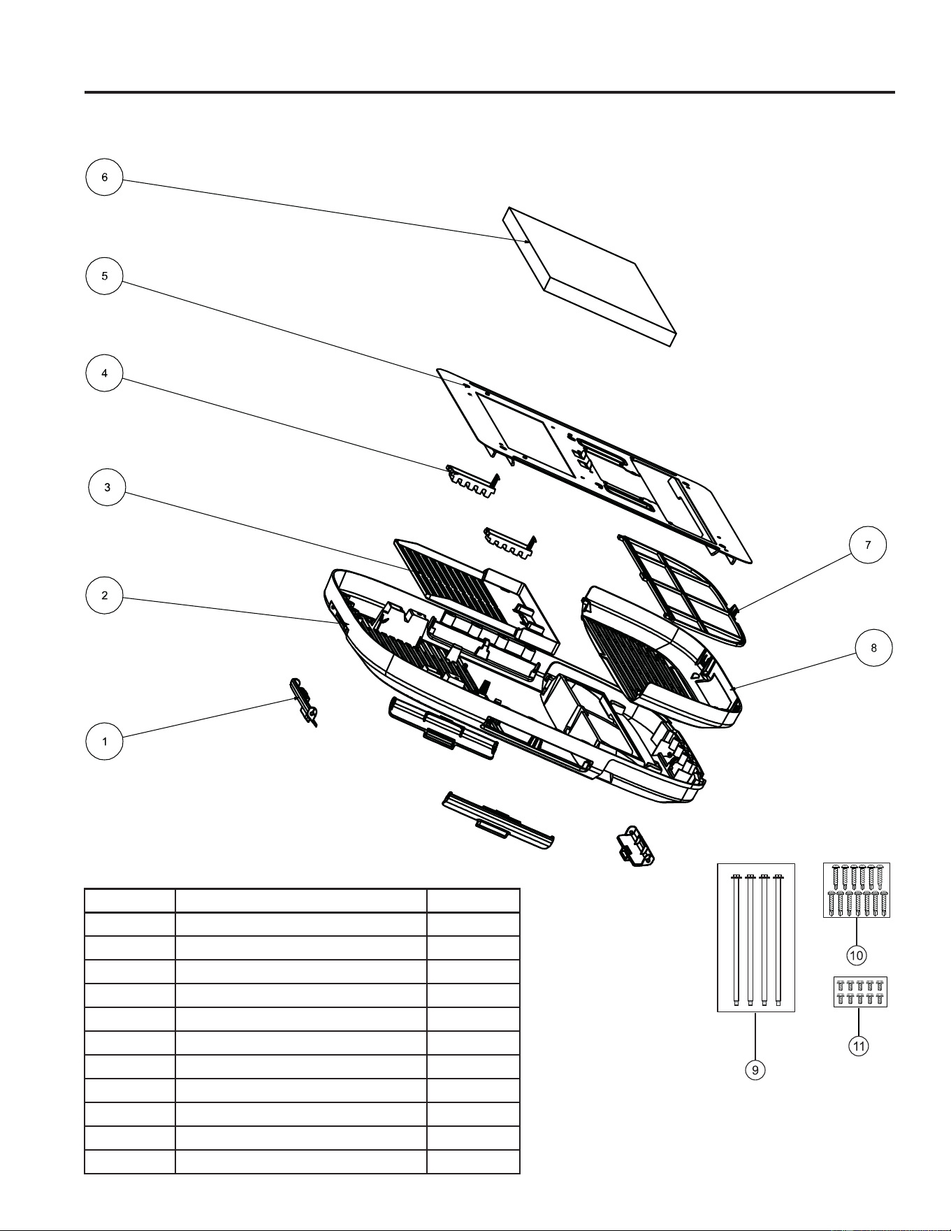
49-5000888 Rev. 5
GUIA DE INSTALACIÓN
Vista Expandida
RGREN
Número Nombre de parte Cantidad
5HMLOODGH'HVFDUJDGH$LUH 4
2 Panel de techo
3 7DSDGHO)LOWUR
4 Filtro
5 Plantilla de montaje
'HIOHFWRUGHGLYLVLyQDpUHD
7 7DSDGHO7RUQLOOR 2
*XtDGH'HVFDUJD'LUHFWDGH$LUH
9 3HUQRVGHPRQWDMH0 4
7RUQLOORVSDUDPDGHUD
7RUQLOORVGHFKDSD
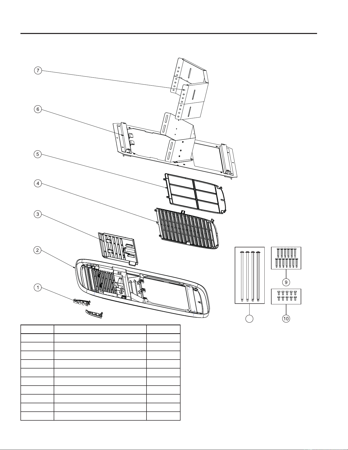
49-5000888 Rev. 5 7
GUIA DE INSTALACIÓN
Vista Expandida
RGRED
8
Número Nombre de parte Cantidad
7DSDGHO7RUQLOOR 2
2 Panel de techo
3 *XtDGH'HVFDUJD'LUHFWDGH$LUH
4 7DSDGHO)LOWUR
5 Sujetador del Filtro + Filtro
Plantilla de montaje
7 'HIOHFWRUGHGLYLVLyQDpUHD
3HUQRVGHPRQWDMH0 4
9 7RUQLOORVSDUDPDGHUD
7RUQLOORVGHFKDSD
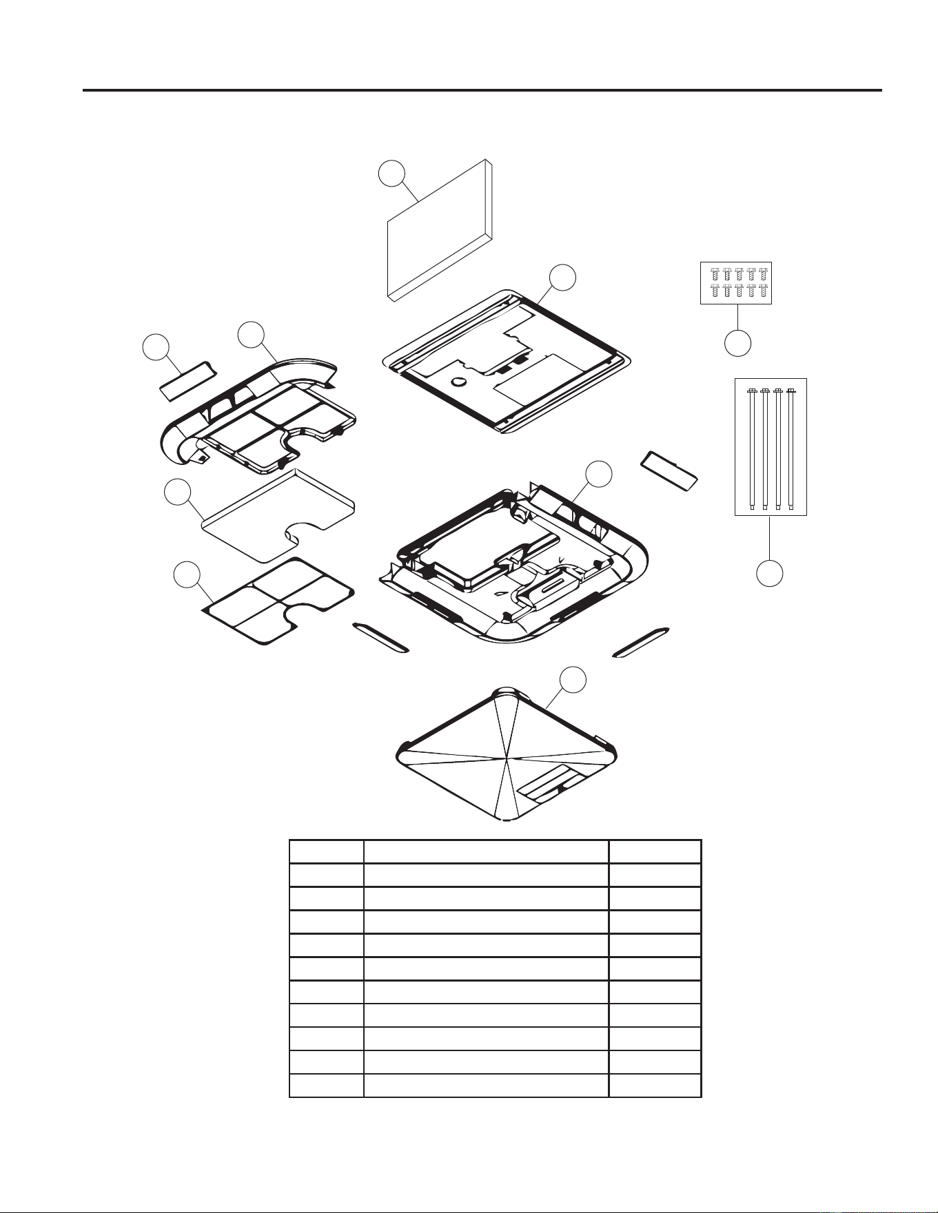
49-5000888 Rev. 5
Vista Expandida
RPREN_ _-Electrónica Sin Conducto
Verifique el contenido de los accesorios suministrados con su aire acondicionado como se muestra a continuación:
1
2
3
10
9
4
5
6
7
8
Número Nombre de parte Cantidad
'HIOHFWRUGHGLYLVLyQDpUHD
2 Plantilla de montaje
3 %DVHGHO3DQHOGHO&LHORUDVR
4
7DSDGHO3DQHOGHO&LHORUDVR
5 Sujetador del Filtro
Filtro
7 %DQGHMDGHO)LOWUR
5HMLOODGH'HVFDUJD/DWHUDO 4
9 3HUQRVGHPRQWDMH0 4
7RUQLOORVGHFKDSD
GUIA DE INSTALACIÓN

49-5000888 Rev. 5 9
GUIA DE INSTALACIÓN
Vista Expandida
RPRED_ _-Electrónica Con Conducto
Verifique el contenido de los accesorios suministrados con su aire acondicionado como se muestra a continuación:
9
8
1
2
3
4
5
6
7
Número Nombre de parte Cantidad
'HIOHFWRUGHGLYLVLyQDpUHD
2 Plantilla de montaje
3 *XtDGH'HVFDUJD'LUHFWD
4 %DVHGHO3DQHOGHO&LHORUUDVR
5
Sujetador del Filtro
Filtro
7 7DSDGHO3DQHOGHO&LHORUDVR
3HUQRVGHPRQWDMH0 4
9 7RUQLOORVGHFKDSD
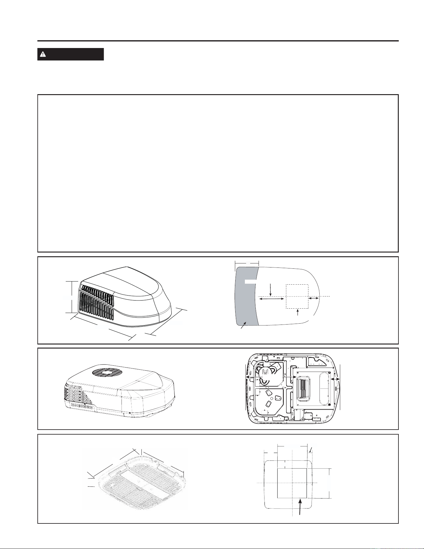
49-5000888 Rev. 5
Instrucciones de instalación
A. REQUISITOS PARA INSTALACIONES EN TECHOS Y DETERMINACIÓN DE LA UBICACIÓN DE
LA INSTALACIÓN
• Los acondicionadores cubiertos en este manual fueron
diseñados para su instalación en techos de vehículos
recreativos
• La instalación de este acondicionador de aire deberá ser
UHDOL]DGDGHDFXHUGRFRQ1)3$\1)3$
• Para una correcta instalación, se deberá contar con una
DEHUWXUDFXDGUDGDGHñ»´[ñ»´ï»´HQHOWHFKR\HQ
el cielorraso del vehículo recreativo.
'HEHUiKDEHUXQHVSDFLRGHHQWUH´\´HQWUHHOFLHORUUDVR
del vehículo recreativo (RV) y el techo para acomodar
nuestro deflector de división de aire.
• Los acondicionadores de aire cubiertos en este manual
cuentan con un diseño que se adapta a aberturas de
ventilación de techos ya existentes. Si no se cuenta con
una abertura de ventilación de techo disponible, utilice las
siguientes pautas:
• La unidad deberá ser instalada de forma centrada entre un
lado y otro del techo del vehículo recreativo.
• La unidad deberá ser instalada en una sección del techo
donde se encuentre nivelada con respecto al techo del
vehículo recreativo, si éste se encuentra en una superficie
plana y nivelada.
• El techo en el punto de instalación podrá tener un ángulo de
LQFOLQDFLyQPi[LPRGHKDFLDHOIUHQWHRODSDUWHWUDVHUD
del vehículo recreativo.
Figura 1: Unidad Exterior de GE Appliances
Figura 2: Unidad Exterior de GE Profile
Figura 3: Unidad Interior Sin Conducto de GE Appliances
(RGRMN)
Figura 4: Unidad Interior Con Conducto de GE Appliances
(RGRED)
Figura 5: Unidad Interior Sin Conducto de GE Profile
(RPREN)
Figura 6: Unidad Interior CON Conducto de GE Profile
(RPRED)
Figura 7: Pautas para el Montaje de Arriba hacia Abajo
ADVERTENCIA
RIESGO DE DESCARGA ELÉCTRICA
Se podrá producir la muerte o daños graves como resultado de no seguir estas instrucciones.
'HVFRQHFWHHOVXPLQLVWURGHFRUULHQWHGH9$&DQWHVGHLQLFLDUODLQVWDODFLyQ\RHOVHUYLFLRWpFQLFR
• Asegúrese de que el producto se encuentre correctamente conectado a tierra, de acuerdo con los códigos aplicables.
• Reemplace todas las piezas y paneles antes del uso.
Figura 1: Unidad Exterior de GE Appliances:
Figura 2: Unidad Exterior de GE Profile:
32.8”
26.2”
13.9”
18”
Center Line of unit
Keep at least 18” free of obstructions at rear of unit.
Roof opening
Front
13 - 3/4”
4 - 3/4”
21.238”
3.834”
Línea central de la unidad
Anterior
Apertura del techo
0DQWHQJDDOPHQRV´OLEUHVGHREVWUXFFLRQHVHQODSDUWH
trasera de la unidad
Figura 3:Unidad Interior Sin Conducto de GE Appliances:
14 - 3/8”
3 - 3/8”
14 - 3/8”
4”
2 - 5/8”
Apertura del techo
INSTRUCCIONES DE INSTALACIÓN
21”
21”
2-1/2”
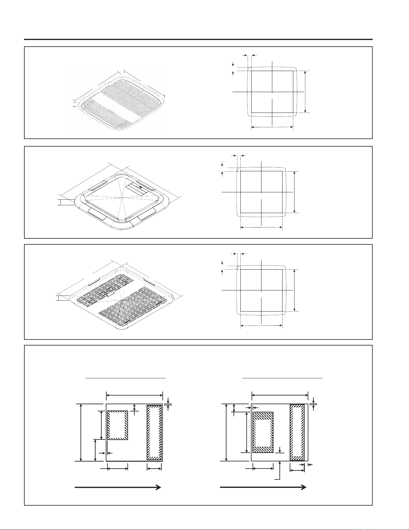
49-5000888 Rev. 5
INSTRUCCIONES DE INSTALACIÓN
Figura 4: Unidad Interior Con Conducto de GE Appliances:
Instrucciones de instalación
Figura 5: Unidad Interior Sin Conducto de GE Profile
Figura 6: Unidad Interior CON Conducto de GE Profile
Roof Opening
14 - 3/8”
14 - 3/8”
1 - 3/8”
1 - 3/8”
Roof Opening
14 - 3/8”
14 - 3/8”
1 - 3/8”
1 - 3/8”
21”
21”
4.1”
17.5”
17.5”
1.2”
Roof Opening
14 - 3/8”
14 - 3/8”
1 - 1/16”
1 - 1/16”
3/4”
17”
17”
Illustration 7: Pautas para el Montaje de Arriba hacia Abajo:
(6-3/4 in)
14-3/8 in
14-3/8 in
3/8 ± ¼ in
1-3/4 in MAX
4-7/8 ± ¼ in
4 ± ¼ in
¼ ± ¼ in
14-3/8 in
14-3/8 in
3/8 in ± ¼
in
2 in MAX
5 in ± ¼ in
(10-1/4 in)
3-5/8 ± ¼ in
3/8 ± ¼ in
1in MAX
2-1/8 in MAX
5-7/8in MAX
0RGHORVGH$OWXUD(VWiQGDU*5&*5+
9,67$'($55,%$+$&,$$%$-2
0RGHORVFRQ3HU¿O,QIHULRU3/&63/+6
9,67$'($55,%$+$&,$$%$-2
Parte
superior e
inferior
3 Lados
Salida de
aire
Salida de
aire
Entrada de aire
Entrada de aire
)5(17('(/$81,'$' )5(17('(/$81,'$'
49-5000888 Rev. 5
C. REQUISITOS ELÉCTRICOS
(VWRVPRGHORVUHTXLHUHQXQWRPDFRUULHQWHGH9\
+]SURWHJLGRFRQXQIXVLEOHGHUHWUDVRGHDPSHUHVRXQ
disyuntor.
8VHXQPtQLPRGHFDEOHGHFREUHGH$:*HQIXQGDGR
sin conexión a tierra.
$VHJ~UHVHGHSDVDUHOFDEOHGHVXPLQLVWURGH´DWUDYpV
del marco. Esto asegurará que haya suficiente cable
disponible para una conexión fácil de la caja de empalmes.
B. REQUISITOS Y PREPARACIÓN
DEL TECHO
Si se usará una abertura de ventilación del techo ya
existente:
'HVWRUQLOOH\UHWLUHODYHQWLODFLyQGHOWHFKRGHO
vehículo recreativo.
2. Selle todos los agujeros y juntas con un sellador
resistente al clima.
3. Mida el ancho y la longitud de la abertura de la
ventilación. Su tamaño deberá ser modificado.
Si no se usará una abertura ya existente, se deberá
realizar una nueva abertura a través del techo y del
cielorraso del vehículo recreativo.
(VWDDEHUWXUD'(%(5ÈHVWDUHQWUHORVPLHPEURV
estructurales del techo.
2. NO corte los miembros estructurales del techo
para crear la abertura para este acondicionador de
DLUH+DFHUHVWRSRGUiRFDVLRQDUGDxRVVREUHHO
vehículo recreativo y el acondicionador de aire.
3. NO cree un punto bajo sobre el techo del vehículo
recreativo. Se podrá acumular agua y gotear a
través de la abertura.
La abertura cuadrada se deberá encerrar con un
marco de un grosor mínimo de ñ»´DILQGHUHVLVWLUOD
carga de los tornillos de compresión.
Asegúrese de brindar un agujero de acceso para el
cableado del vehículo recreativo hacia el frente de la
DEHUWXUDGHñ»´[ñ»´
El techo y la estructura del vehículo recreativo en el
punto de instalación deberán ser lo suficientemente
fuertes como para soportar el acondicionador de aire
VLQQLQJ~QWLSRGHGHVYLDFLyQ8QDGHVYLDFLyQKDUi
que el agua se acumule en la junta del acondicionador
de aire, lo cual podrá ocasionar goteos.
D. COLOCACIÓN DE LA UNIDAD EN
EL TECHO
PRECAUCIÓN
RIESGO AL LEVANTAR
Asegúrese de que se utilicen
métodos y controles al levantar la unidad hasta el
techo del vehículo recreativo. Si no se cumple con
esto, se podrán producir lesiones.
5HWLUHODXQLGDGGHOHPEDODMH\HOLPLQHHOPLVPR
2. No deslice la unidad sobre su junta de montaje.
Cualquier daño sobre la junta podrá generar
goteos. Contando con dos personas, levante
la unidad y coloque la misma sobre la unidad
preparada. El frente de la unidad deberá mirar en la
dirección hacia la cual el vehículo recreativo viaja.
Si no se siguen estas instrucciones, se podrán
producir daños sobre el ventilador del condensador
y la bobina.
ADVERTENCIA
Es importante leer y
entender estas instrucciones de instalación antes de
la instalación y el uso.
Si la unidad no se instala de forma segura en el
vehículo recreativo antes de mover este último, se
podrán producir lesiones personales o la muerte.
No utilice la unidad ni el vehículo recreativo hasta que
la unidad se encuentre completamente asegurada en
el techo.
7UDLJDHOHQVDPEOHGHOFLHORUUDVRFRQWRGRV
los materiales de montaje provistos al vehículo
recreativo. Si usará un ensamble interior 7RGRHO
trabajo en el exterior del vehículo recreativo está
ahora completo.
NOTA:
Para las siguientes instalaciones de ensambles interiores,
proceda a la sección correspondiente:
5*5016HFFLyQ(SiJLQD
5*5(16HFFLyQ(SiJLQD
535(16HFFLyQ(SiJLQD
5*5('6HFFLyQ)SiJLQD
535('6HFFLyQ)SiJLQD
Instrucciones de instalación
INSTRUCCIONES DE INSTALACIÓN

49-5000888 Rev. 5
MONTAJE VERTICAL
6LHOFLHORUUDVRFXHQWDFRQGRVDSHUWXUDVLQGLYLGXDOHVFRPRVHPXHVWUDHQOD6HFFLyQ$)LJXUDSURFHGDDOSDVR$'H
RWURPRGRSURFHGDDOSDVR%
$8VWHGGHEHUiLQVWDODUHODFFHVRULRGHODMXQWDGHJRPDHVSXPD5*5)*$SDUDHYLWDUTXHODHQWUDGD\VDOLGDVH
mezclen en la circulación del aire. Incline la unidad hacia arriba y pele el adhesivo para liberar el revestimiento sobre
ODSDUWHWUDVHUDGHODMXQWDGHJRPDHVSXPD5*5)*$$GKLHUDODMXQWDDODSDUWHLQIHULRUGHODFKDURODGHODEDVHGH
la unidad que está entre las aberturas de entrada y salida de aire.
%,QFOLQHODXQLGDGKDFLDDUULED\SRVLFLRQHHOGHIOHFWRUGHPRGRWDOTXHVHSDUHODFLUFXODFLyQGHDLUHGHHQWUDGDFRQ
la de salida sin que haya interferencia con el conducto en la abertura del techo. Luego, vuelva a instalar la unidad,
manteniendo la posición de referencia en la Sección A.
2. Retire la carcasa exterior desenroscando los 4 tornillos alrededor del perímetro de la unidad y deje la misma a un costado.
3. 5HWLUHODWDSDGHOSROLSURSLOHQRH[SDQGLGR(33\JXDUGHODPLVPDFRQODWDSDGHODFDUFDVD+DJDFLUFXODUORVFDEOHVGH
VXPLQLVWURGHFRUULHQWHGH9$&\9'&DVtFRPRWDPELpQHOFDEOHDGRGHOWHUPRVWDWRGHOYHKtFXORUHFUHDWLYRGHVGH
la abertura del techo del vehículo recreativo y través de la abertura de la entrada de aire oval en el frente de la charola
de la base del acondicionador de aire.
4. ,GHQWLILTXHODViUHDVGHQWDGDVGHODSLH]DLQIHULRUGHOD7DSDGHOSROLSURSLOHQRH[SDQGLGR(33(VWDVXELFDFLRQHV
se encuentran donde se deben colocar los tirafondos para asegurar el acondicionador de aire al techo del vehículo
recreativo.
5. 6LUHDOL]DUiHOPRQWDMHHQXQDHVWUXFWXUDGHPDGHUDXVHWLUDIRQGRVFRQFDOLILFDFLyQSDUDPDGHUD\URWHKDVWDOLEUDV
pulgadas. Si realizará el montaje en una estructura de aluminio, use tirafondos con calificación para metal y rote hasta
OLEUDVSXOJDGDV
&RQVXOWHHO0DQXDOGH&RQWUROGH8VR\&XLGDGRSDUDFRQHFWDUODFRUULHQWHWHUPLVWRUHV\XQWHUPRVWDWRDVXFRQWURO
7. Con el control cerrado y ajustado de forma segura, deslice el mismo en el soporte de montaje sobre el frente de la unidad.
Las lengüetas que sobresalen desde el lateral del control se deberán deslizar en la cavidad del soporte.
8VHGHORVWRUQLOORVSDUDSODQFKDPHWiOLFDSURYLVWRVFRQHOFRQWUROSDUDDVHJXUDUHVWH~OWLPRDOVRSRUWHDWUDYpVGHODV
lengüetas que sobresalen.
9. Vuelva a instalar la tapa del polipropileno expandido (EPP), asegurando una alineación adecuada con la base del
polipropileno expandido (EPP)k. No hacer esto producirá como resultado un rendimiento inferior del acondicionador de
aire.
Vuelva a instalar la carcasa exterior, colocando los 4 tornillos retirados en el paso 2.
8VWHGLQVWDOyODXQLGDGGHIRUPDH[LWRVD
INSTRUCCIONES DE INSTALACIÓN
Instrucciones de instalación
49-5000888 Rev. 5
E1. INSTALACIÓN SIN CONDUCTO
(
RGRMN, RGREN, & RPREN)
'HVGHGHQWURGHOYHKtFXORUHFUHDWLYRUHDOLFHXQFRQWURO
doble del posicionamiento y alineación de la junta sobre
ODDEHUWXUDGHOWHFKR'HVHUQHFHVDULRUHDOLFHDMXVWHV
El acondicionador de aire podrá ser movido y ajustado
empujando hacia arriba desde dentro del vehículo
recreativo.
2. Alcance la bandeja de la base y tire del cable de corriente
eléctrica desde el acondicionador de aire a través de la
abertura del cielorraso.
3. Mida el grosor entre el cielorraso y el techo.
4. Corte las filas desde la parte inferior del separador de
gomaespuma, de acuerdo con la siguiente tabla:
Grosor del cielorraso hasta el techo Filas a cortar
Mínimo Máximo
22.5
2.5 3
3.5 4
4.5 5 4
55.52
5.5
Mejor Procedimiento:
Corte una fila por vez, y controle la posición del separador
en la instalación. Con la gomaespuma superior comprimida
sobre la bandeja de la base del acondicionador de aire, la
parte inferior de la fila deberá estar nivelada con la abertura
del cielorraso.
5. Coloque el deflector de gomaespuma en la posición que
se encuentra entre las 2 placas de sujeción.
3UHVLRQHODSODQWLOODGHPRQWDMHGHQWURGHODDEHUWXUDGHO
techo, y comience a enroscar de forma manual cada uno
de los 4 pernos de montaje a través de las tuercas de la
bandeja de la base.
7. Apriete los 4 pernos de manera uniforme a 35 ± 5
pulgadas libras con una llave dinamométrica de al menos
SXOJDGDVOLEUDV,QFOXVRVHUHTXLHUHFRPSUHVLyQSDUD
evitar fugas a través de la junta.
ALTO!
Para el modelo RGRMN vaya a la sección E2 – Cableado
Mecánico Sin Conducto
Para los modelos RGREN y RPREN vaya a la sección E3
– Cableado Electrónico Sin Conducto
E1. INSTALACIÓN SIN CONDUCTO
(RGRMN, RGREN, & RPREN)
(cont.)
$VHJXUHHOSDQHOGHOFLHORUUDVRDODSODQWLOODGHPRQWDMH
usando 2 tornillos para plancha metálica sobre los 2
agujeros de la cavidad del filtro. El filtro deberá ser
retirado para instalar los tornillos.
9. Aplicando fuerza sobre el centro del panel del cielorraso,
conduzca los dos tornillos de madera por los agujeros
debajo de la rejilla ubicada en la posición más cercana
a la guía de descarga directa. Los puertos de descarga
lateral se deberán retirar para permitir el acceso a los
agujeros de montaje.
&RORTXHORVWRUQLOORVGHPDGHUDUHVWDQWHVXELFDGRV
debajo de los puertos de descarga lateral. Acceda a los
agujeros de montaje a través del método que aparece
en el paso anterior.
9XHOYDDLQVWDODUHOILOWUR
/DLQVWDODFLyQHVWiFRPSOHWD&RQVXOWHODVHFFLyQGH
³&RQWUROHV´HQODSiJLQDDQWHVGHLQWHQWDUXWLOL]DUHO
acondicionador de aire.
Instrucciones de instalación
INSTRUCCIONES DE INSTALACIÓN

49-5000888 Rev. 5
E2. INSTALACIÓN MECÁNICA SIN
CONDUCTO (RGRMN_ _)
5HWLUHODWDSDGHOFRQHFWRUGH\SHUQRVGHOHQVDPEOH
del cielorraso retirando los 2 tornillos.
2. Enchufe el cable con el conector de 3 y 4 pernos en los
respectivos receptáculos sobre la plantilla de montaje.
3. Vuelva a instalar la tapa del conector de 3 y 4 pernos,
conduciendo el cable a través de la abertura con forma de
8\WHQLHQGRFXLGDGRGHQRSHOOL]FDUORVFDEOHV
'HVLQVWDOHODWDSDGHODFDMDGHHPSDOPHVUHWLUDQGRORV
tornillos.
&RQGX]FDHOFDEOHGHVXPLQLVWURGHFRUULHQWHGH
VAC a través del aliviador de tensión de 2 tornillos del
ensamble del cielorraso. Luego, ajuste el aliviador de
tensión, asegurándose de no dañar los cables.
8WLOL]DQGRORVFRQHFWRUHVGHFDEOHVDGHFXDGRVSDUDHO
calibre de los cables, conecte la línea al negro, el neutro
al blanco, y el cable a tierra al verde.
8WLOL]DQGRFLQWDDLVODGRUDDVHJXUHORVFRQHFWRUHVSDUD
evitar cualquier posible movimiento debido a vibraciones
del vehículo. Si se usan tuercas para cables, asegúrese
de aplicar la cinta en la dirección en que se ajustó la
tuerca, a fin de que la conexión no se afloje de forma no
intencional.
3RVLFLRQHORVFDEOHV\FRQH[LRQHVGHOVXPLQLVWURGH
corriente dentro de la caja de empalmes, y vuelva a
instalar la tapa de la caja de empalmes.
9. Alinee el panel plástico del cielorraso con la plantilla de
montaje, usando los postes de la perilla de control como
guías.
,QVWDOHODVSHULOODVGHFRQWURODVHJXUDQGRTXHHO
FRQWRUQRFRQIRUPDHQ'HVWpFRUUHFWDPHQWHDOLQHDGR
con los postes.
3URFHGDDOSDVRGHOD6HFFLyQ(
E3. INSTALACIÓN ELECTRÓNICA
SIN CONDUCTO (RGREN_ _ &
RPREN__)
'HVLQVWDOHODSODFDFLHJDGHODSODQWLOODGHPRQWDMH
retirando los 3 tornillos.
2. Monte la caja de control principal (RGREC_A) a la plantilla
de montaje usando 2 tornillos.
3. Retire los 3 tornillos de la base de la caja de control
principal, permitiendo que la base se abra sobre sus
bisagras. El tablero de control está ahora visible y
accesible.
4. &RQGX]FDHOFDEOHGHFRUULHQWHGH9$&DWUDYpVGHO
amortiguador de refuerzo de la caja de control. Luego,
ajuste el aliviador de tensión, asegurándose de no dañar
los cables.
5. 8VDQGRFRQHFWRUHVGHFDEOHVFRQFDOLILFDFLyQSDUDHO
calibre de sus cables, conecte la línea al azul, el neutro al
EODQFR\WLHUUDDOYHUGHDPDULOOR
8WLOL]DQGRFLQWDDLVODGRUDDVHJXUHORVFRQHFWRUHVSDUD
evitar cualquier movimiento posible debido a vibraciones
del vehículo. Si se usan tuercas para cables, asegúrese
de colocar la cinta en la dirección en que se ajustó la
tuerca, a fin de que la conexión no se afloje de forma no
intencional.
E3. INSTALACIÓN ELECTRÓNICA
SIN CONDUCTO (RGREN_ _ &
RPREN__)
(cont.)
7. Conduzca los conectores de 3 y 4 pernos desde la unidad
H[WHULRUDWUDYpVGHODDEHUWXUDFRQIRUPDGH8HQOD
FDMDGHFRQWURO+DJDFRLQFLGLUHVWRVFRQHFWRUHVFRQVXV
enchufes correspondientes en el tablero de control.
&RQHFWHHOFDEOHGHVXPLQLVWURGHFRUULHQWHGH9'&\
el cable a tierra proveniente del vehículo recreativo a las
WHUPLQDOHVGHOFRQHFWRUGHSHUQRVH[WUDtEOHVGH©9´
\³*1'´7LHUUDUHVSHFWLYDPHQWH&RQVXOWHHOPDQXDO
GH8VR\&XLGDGRGHOFRQWUROSDUDFRQHFWDUVXFRQWURO
específico al termostato de pared.
9. La unidad cuenta con 2 termistores preinstalados en la
unidad del acondicionador de aire, los cuales se deberán
conectar al tablero del control principal. El sensor de
congelación de la bobina interior es un conector de 2
SHUQRVTXHVHGHEHHQFKXIDUHQODWHUPLQDO7GHOWDEOHUR
de control, y el sensor de temperatura de salida del aire
interior es un conector de 3 pernos que se debe enchufar
DXQFRQHFWRU7HQHOWDEOHURGHFRQWUROSULQFLSDO/RV
modelos con bomba de calor cuentan con un conector de
4 pernos que contiene un termistor con bobina exterior
y un termistor de temperatura ambiente exterior – éste
VHGHEHFRQHFWDUDODWHUPLQDO77GHOWDEOHURGH
control principal. No realizar estas conexiones específicas
producirá códigos de falla y esto podrá hacer que la
unidad no funcione.
6LHVWiXWLOL]DQGRHOVHQVRUSDUDVDOD5*5(6$FRQ
la unidad del acondicionador de aire, deberá conectar
el sensor al tablero de control principal a través de la
WHUPLQDOGHSHUQRVH[WUDtEOHFRQODHWLTXHWD³/6´
OPCIONAL: Si desea que la unidad del acondicionador
de aire esté conectada al sistema de desbordamiento
de carga de su vehículo recreativo (no incluido en todos
los vehículos recreativos), será necesario conectar
el sistema de desbordamiento de carga al tablero de
FRQWUROSULQFLSDO6LXVDUiXQFRQWURO5*5(&$FRQHFWH
el sistema de desbordamiento de carga a través del
FRQHFWRUGHSHUQRVH[WUDtEOHFRQODHWLTXHWD³/6´
Si usará un control RGREC2A, conecte el sistema de
desbordamiento de carga a través de la terminal en el
FRQHFWRUGHSHUQRVH[WUDtEOHFRQODHWLTXHWD³/6´
OPCIONAL: Si cuenta con un horno que desee controlar
a través del termostato, conecte el horno a las dos
WHUPLQDOHVFRQODHWLTXHWD³)85´HQHOFRQHFWRUGH
pernos extraíble. Consulte el manual del propietario de
su horno.
OPCIONAL:7RGRVORVFRQWUROHVFXHQWDQFRQODRSFLyQ
de funcionalidad de inicio con generador automático. Si
desea activar esta función, conecte el generador a las
GRVWHUPLQDOHVFRQODHWLTXHWD³*(1´GHOFRQHFWRUGH
pernos extraíble
0DQWHQLHQGRWRGDVODVFRQH[LRQHVGHQWURGHODFDMDGH
control, conduzca los cables a través de la abertura con
IRUPDGH8VREUHHOODWHUDO/XHJRWHQLHQGRFXLGDGRGH
QRSHOOL]FDUURPSHUQLQJ~QFDEOHJLUHODEDVHGHODFDMD
de control principal hacia arriba y vuelva a instalar los
3 tornillos retirados en el Paso 3 para sellar la caja de
control.
INSTRUCCIONES DE INSTALACIÓN
Instrucciones de instalación

49-5000888 Rev. 5
E3. INSTALACIÓN ELECTRÓNICA
SIN CONDUCTO (RGREN_ _ &
RPREN__)
(cont.)
,QVWDOHODSODFDGHODWDSDXWLOL]DQGRORVWRUQLOORV
adheridos a la plantilla de montaje y los 2 tornillos que
se adhieren a la caja de control principal.
3DUDHOPRGHOR5$5(1SURFHGDDOSDVRGHOD
6HFFLyQ(3DUDHOPRGHOR5$5(1SURFHGDDOSDVR
GHOD6HFFLyQ(
$VHJXUHODEDVHGHOSDQHOGHOFLHORUUDVRDODSODQWLOODGH
montaje usando 4 tornillos para plancha metálica.
,QVWDOHHOILOWUR\HOVXMHWDGRUGHOILOWURHQODEDQGHMDGHO
filtro.
$OLQHHODEDQGHMDGHOILOWURFRQODVUDQXUDV
correspondientes en la base del panel del cielorraso, y
deslice la bandeja del filtro en su posición.
8VDQGRODVIXQFLRQHVGHJXtDFRQUHOLHYHVREUHODEDVH
del panel del cielorraso, instale la tapa del panel del
cielorraso.
/DLQVWDODFLyQHVWiFRPSOHWD&RQVXOWHODVLQVWUXFFLRQHV
de funcionamiento del cielorraso antes de iniciar el uso.
F. INSTALACIÓN ELECTRÓNICA
SIN CONDUCTO (RGRED &
RPRED)
'HVGHGHQWURGHOYHKtFXORUHFUHDWLYRUHDOLFHXQFRQWURO
doble del posicionamiento y alineación de la junta sobre
ODDEHUWXUDGHOWHFKR'HVHUQHFHVDULRUHDOLFHDMXVWHV
El acondicionador de aire podrá ser movido y ajustado
empujando hacia arriba desde dentro del vehículo
recreativo.
2. Alcance la bandeja de la base y tire del cable de corriente
eléctrica desde el acondicionador de aire a través de la
abertura del cielorraso.
3. Empuje la plantilla de montaje del cielorraso dentro de la
abertura del techo, y comience a enroscar manualmente
cada uno de los 4 tornillos de montaje a través de las
tuercas de la bandeja de la base.
4. Ajuste los 4 tornillos de forma pareja hasta las 35 ± 5
OLEUDVXVDQGRXQDWRUVLyQPtQLPDGHSXOJDGDVOLEUD
Se requiere una compresión pareja a fin de evitar goteos
a través de la junta.
5. Coloque el separador en su posición sobre el ensamble
del cielorraso. Asegúrese de que el separador sea
presionado contra la bandeja de la base, formado un
sellado hermético.
0RQWHHOVHSDUDGRUVREUHODSODQWLOODGHPRQWDMHXVDQGR
tres tornillos.
7. Monte el separador sobre el tablón del marco usando dos
tornillos, y creando un sellado hermético. Para cielorrasos
adicionales, use cinta de aluminio para sellar posibles
pérdidas entre el marco de madera y el deflector.
0RQWHODFDMDGHFRQWUROSULQFLSDO5*5(&BBVREUHOD
plantilla de montaje usando cuatro tornillos.
F. INSTALACIÓN ELECTRÓNICA
SIN CONDUCTO (RGREN&
RPRED)
(cont.)
9. Retire los tres tornillos de la caja de control principal,
permitiendo que la sección inferior se abra girando sobre
la bisagra. El tablero de control está ahora visible y
accesible.
'LULMDHOFDEOHGHFRUULHQWHGH9$&DWUDYpVGHO
amortiguador de refuerzo de la caja de control. Ajuste
el amortiguador de refuerzo, asegurándose de no dañar
los cables.
8VDQGRFRQHFWRUHVGHFDEOHVFRQFDOLILFDFLyQSDUDHO
calibre de sus cables, conecte la línea al azul, el neutro
DOEODQFR\WLHUUDDOYHUGHDPDULOOR
8VDQGRFLQWDDLVODGRUDDVHJXUHORVFRQHFWRUHVDILQ
de evitar cualquier movimiento posible debido a una
vibración del vehículo.
&RQGX]FDORVFRQHFWRUHVGH\SHUQRVGHVGHOD
XQLGDGH[WHULRUDWUDYpVGHODDEHUWXUDFRQIRUPDGH8
HQODFDMDGHFRQWURO+DJDFRLQFLGLUHVWRVFRQHFWRUHV
con sus enchufes correspondientes en el tablero de
control.
&RQHFWHHOFDEOHGHVXPLQLVWURGHFRUULHQWHGH9'&\
el cable a tierra proveniente del vehículo recreativo a las
WHUPLQDOHVGHOFRQHFWRUGHSHUQRVH[WUDtEOHVGH©9´
\³*1'´7LHUUDUHVSHFWLYDPHQWH&RQVXOWHHOPDQXDO
GH8VR\&XLGDGRGHOFRQWUROSDUDFRQHFWDUVXFRQWURO
específico al termostato de pared.
/DXQLGDGFXHQWDFRQWHUPLVWRUHVSUHLQVWDODGRV
en la unidad del acondicionador de aire, los cuales
se deberán conectar al tablero del control principal.
El sensor de congelación de la bobina interior es
un conector de 2 pernos que se debe enchufar en
ODWHUPLQDO7GHOWDEOHURGHFRQWURO\HOVHQVRUGH
temperatura de salida de aire interior es un conector de
SHUQRVTXHVHGHEHHQFKXIDUDXQFRQHFWRU7HQHO
tablero de control principal. Los modelos con bomba de
calor cuentan con un conector de 4 pernos que contiene
un termistor de temperatura con bobina exterior y un
termistor de temperatura ambiente exterior – éste se
GHEHFRQHFWDUDODWHUPLQDO77GHOWDEOHURGHFRQWURO
principal. No realizar estas conexiones específicas
producirá códigos de falla y esto podrá producir la
pérdida del funcionamiento de la unidad.
Instrucciones de instalación
INSTRUCCIONES DE INSTALACIÓN

49-5000888 Rev. 5
F. INSTALACIÓN ELECTRÓNICA SIN CONDUCTO (RGRED & RPRED) (cont.)
6LHVWiXWLOL]DQGRHOVHQVRUSDUDVDOD5*5(6$FRQ
la unidad del acondicionador de aire, deberá conectar
el sensor al tablero de control principal a través de la
WHUPLQDOGHSHUQRVH[WUDtEOHFRQODHWLTXHWD³/6´
OPCIONAL: Si desea que la unidad del acondicionador
de aire esté conectada al sistema de desbordamiento
de carga de su vehículo recreativo (no incluido en todos
los vehículos recreativos), será necesario conectar el
sistema de desbordamiento de carga al tablero de control
SULQFLSDO6LXVDUiXQFRQWURO5*5(&$FRQHFWHHO
sistema de desbordamiento de carga con el conector de 2
SHUQRVH[WUDtEOHFRQODHWLTXHWD³/6´6LXVDUiXQFRQWURO
RGREC2A, conecte el sistema de desbordamiento de
FDUJDFRQODWHUPLQDOHQHOFRQHFWRUGHSHUQRVH[WUDtEOH
FRQODHWLTXHWD³/6´
OPCIONAL: Si cuenta con un horno que desee controlar
a través del termostato, conecte el horno a las dos
WHUPLQDOHVFRQODHWLTXHWD³)85´HQHOFRQHFWRUGH
pernos extraíble. Consulte el manual del propietario de su
horno.
0DQWHQLHQGRWRGDVODVFRQH[LRQHVGHQWURGHODFDMDGH
control, conduzca los cables a través de la abertura con
IRUPDGH8VREUHHOODWHUDO/XHJRWHQLHQGRFXLGDGRGH
QRSHOOL]FDUURPSHUQLQJ~QFDEOHJLUHODEDVHGHODFDMD
de control principal hacia arriba y vuelva a instalar los
3 tornillos retirados en el Paso 9 para sellar la caja de
control.
3DUDHOPRGHOR5*5('DOLQHHHOSDQHOSOiVWLFRGHO
cielorraso con la placa de montaje. Para el modelo
535('DOLQHHODEDVHGHOSDQHOGHOFLHORUUDVRFRQOD
plantilla de montaje.
8VDQGRORVWRUQLOORVPHWiOLFRVSURYLVWRVDVHJXUHHO
panel del cielorraso o la base del panel del cielorraso a la
plantilla de montaje. El filtro y la tapa del filtro deberán ser
retirados para instalar estos tornillos.
22. 3DUDHO5*('LQVWDOHHOILOWUR\ODWDSDGHOILOWUR
presionando la lengüeta individual sobre el centro de la
tapa del filtro y calce la misma en la cavidad del filtro.
Luego instale la tapa con tornillo izquierdo y derecho,
insertando los mismos en sus respectivas cavidades.
3DUDHOPRGHOR535('LQVWDOHHOVXMHWDGRUGHOILOWURFRQ
el filtro en la base del panel del cielorraso, deslizando el
mismo debajo de las dos solapas de la base del panel
del cielorraso y luego rotando el mismo hacia abajo.
Luego alinee la tapa del panel del cielorraso a través de
la perilla deslizable y presione hacia arriba en la dirección
del cielorraso para calzar la tapa del panel del cielorraso
sobre su posición.
24. La instalación está completa. Consulte las instrucciones
de funcionamiento del cielorraso antes de iniciar el uso.
23&,21$/7RGRVORVFRQWUROHVFXHQWDQFRQODRSFLyQ
de funcionalidad de inicio con generador automático. Si
desea activar esta función, conecte el generador a las
GRVWHUPLQDOHVFRQODHWLTXHWD³*(1´GHOFRQHFWRUGH
pernos extraíble.
INSTRUCCIONES DE INSTALACIÓN
Instrucciones de instalación
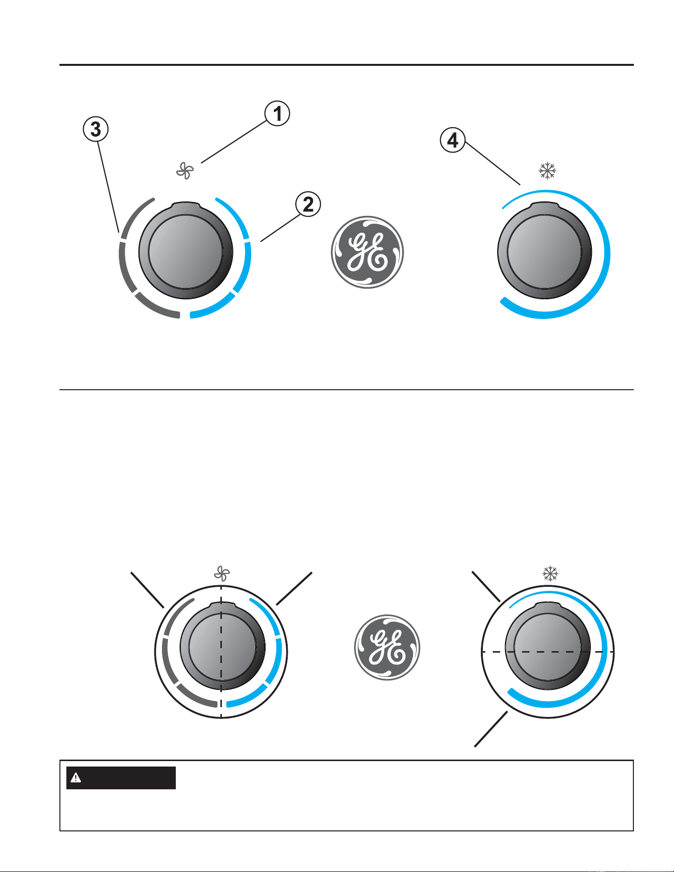
49-5000888 Rev. 5
Controles
Controles
1. Apagado
El acondicionador de aire está en la posición de apagado.
2. Modos del Acondicionador de Aire
En estas posiciones, el compresor y los ventiladores
funcionarán para brindar aire fresco. Los tres modos
corresponden a las velocidades baja, media y alta del
ventilador.
3. Modo de Sólo Ventilador
En estos modos, los ventiladores hacen circular aire en el
vehículo recreativo. Los tres modos corresponden a las
velocidades baja, media y alta del ventilador.
4. Selección de Temperatura
Esta perilla determina el punto de configuración de
temperatura de la sala. Gire esta perilla para incrementar o
reducir el nivel de frío del acondicionador de aire en la sala.
Las funciones y la apariencia podrán variar.
Controles del Acondicionador de Aire
PRECAUCIÓN
A fin de evitar que el disyuntor se active, espere por lo menos 3 minutos para apagar el compresor y volver a encenderlo (es
GHFLUHVSHUHPLQXWRVDQWHVGHPRYHUHOGLDOGHVGHODSRVLFLyQ$D%\QXHYDPHQWHD$RSDUDSDVDUGHODSRVLFLyQ$
D%\QXHYDPHQWHD$VHPXHVWUDHQODLPDJHQVXSHULRU
Ma
x
Cool
With A
C
O
ff
F
an S
p
eed
T
em
p
erature
M
ax
C
ool
W
ith A
C
O
f
f
F
an
S
peed
T
em
p
eratur
e
Position
2B
Position
2A
Position
1A
Position
1B
USO DEL ACONDICIONADOR DE AIRE
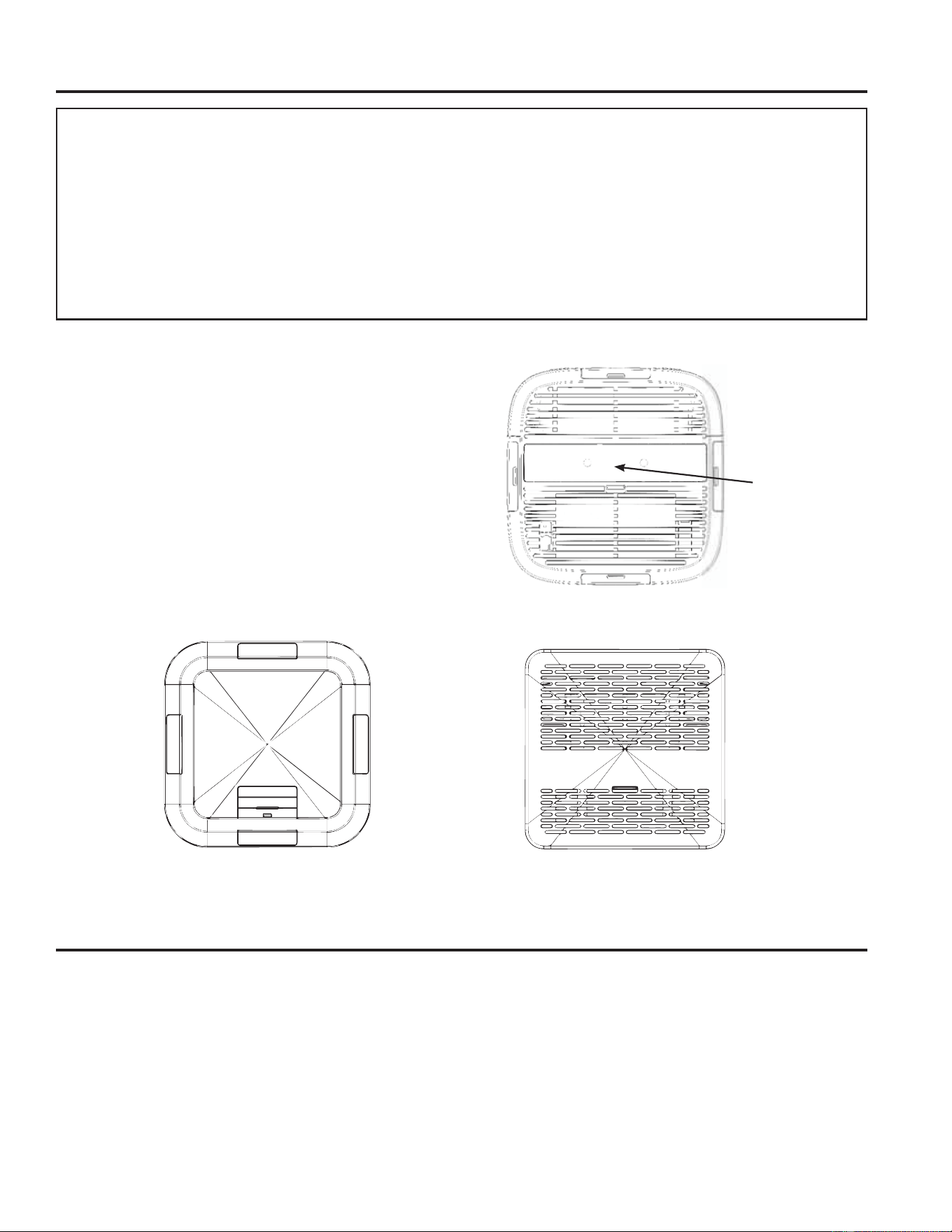
49-5000888 Rev. 5
USO DEL ACONDICIONADOR DE AIRE
Uso del Acondicionador de Aire
Sonidos de operación normales
Cuando el aire acondicionado esté funcionando normalmente, es posible que escuche sonidos como los siguientes:
Ŷ*RWDVGHDJXDTXHFDHQVREUHHOFRQGHQVDGRUORTXHSURGXFHXQVRQLGRPHWiOLFRRXQFKDVTXLGR/DVJRWDVGHDJXDD\XGDQ
a que el condensador se enfríe.
Ŷ0RYLPLHQWRGHDLUHTXHVHRULJLQDHQHOYHQWLODGRU
Ŷ&KDVTXLGRVTXHVHRULJLQDQSRUHOFLFORGHOWHUPRVWDWR
Ŷ=XPELGRVDJXGRVRUXLGRVSDOSLWDQWHVSURGXFLGRVSRUHOFRPSUHVRUPRGHUQRGHDOWDHILFLHQFLDDOLQLFLDU\ILQDOL]DUVXFLFOR
IMPORTANTE:
• Al apagar el acondicionador de aire, espere por lo menos
3 minutos antes de volver a encenderlo. Esto evitará que
el compresor se sobrecargue. Este retraso de 3 minutos
también se aplica cuando se pasa del modo frío a ventilador
y a frío nuevamente.
• No utilice el acondicionador de aire en el modo Cool (Frío)
cuando la temperatura exterior se encuentre por debajo
GHORV)&/DERELQDGHOHYDSRUDGRULQWHULRU
se congelará, y el acondicionador de aire no funcionará
correctamente.
• A fin de evitar que el disyuntor se active, al ajustar el
termostato o las velocidades del ventilador espere 3 minutos
entre los ciclos del compresor, a fin de contar con tiempo
suficiente para que la presión del refrigerante se nivele.
Dirección del Aire
8VHODSDODQFDSDUDDEULURFHUUDUODYHQWLODFLyQVREUHODFDUD
del panel de control.
Abra o cierre los 4 puertos laterales para ajustar el flujo de aire
proveniente del acondicionador de aire.
Vista Frontal
La palanca
se encuentra
ubicada entre
las dos perillas.
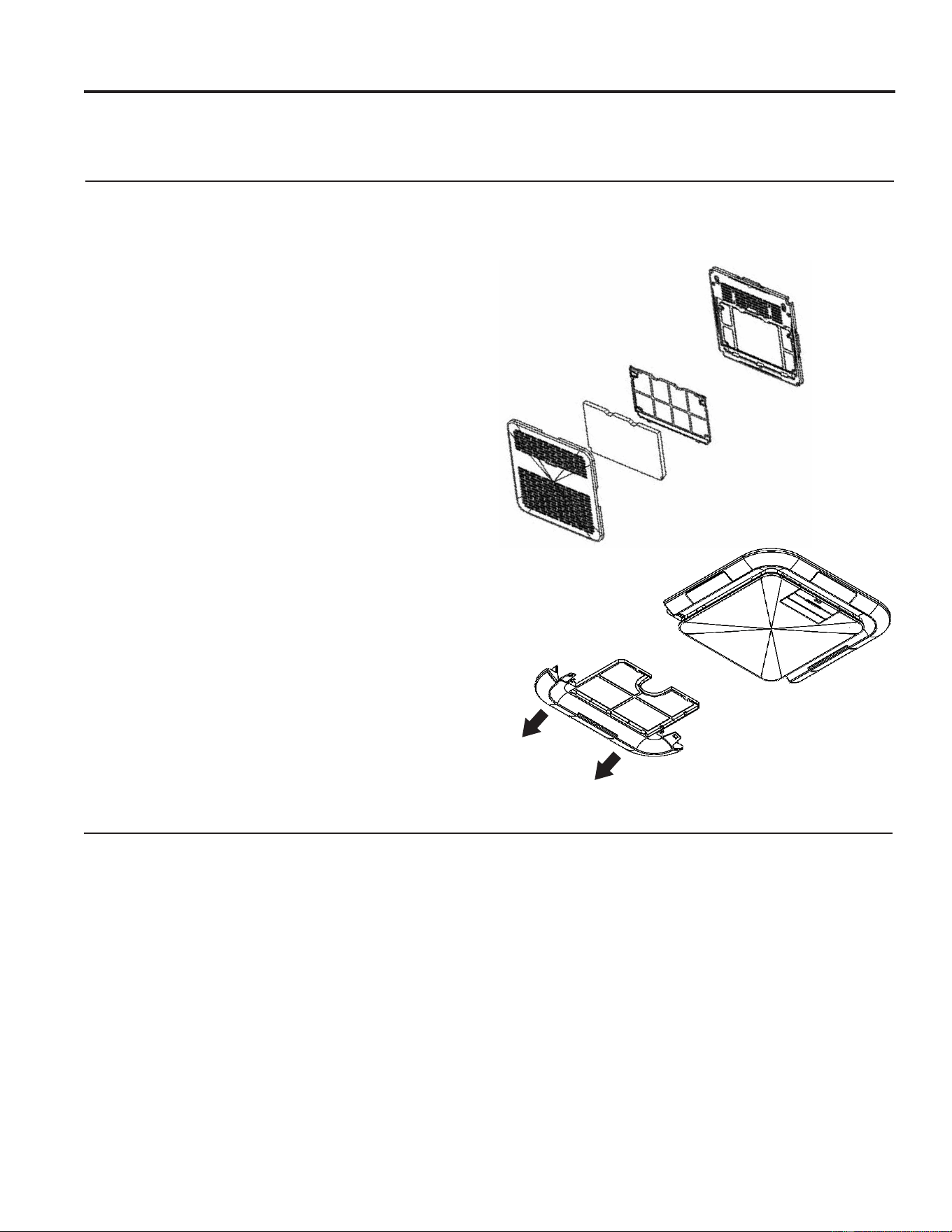
49-5000888 Rev. 5
Cuidado y limpieza
Parrilla y Caja
Apague el acondicionador de aire y retire el enchufe del
tomacorriente antes de limpiar.
Para limpiar, use agua y un detergente suave. No use
blanqueadores ni abrasivos.
Mantenimiento anual
Su aire acondicionado requiere mantenimiento anual para
garantizar un funcionamiento óptimo y estable todo el año.
Llame a su distribuidor autorizado local para programar una
UHYLVLyQDQXDO8VWHGGHEHSDJDUORVJDVWRVGHODLQVSHFFLyQ
anual.
Filtro de Aire
El filtro de aire se deberá controlar cada 2 semanas y se lo
deberá limpiar, de ser necesario.
No utilice el acondicionador de aire sin un filtro, ya que la
suciedad y las pelusas producirán atascamientos y reducirán su
funcionamiento.
Limpieza del filtro de aire
$SDJXHHODLUHDFRQGLFLRQDGR
2. Retire la tapa del filtro de aire de acuerdo con las figuras
que aparecen para poder obtener acceso al filtro.
8WLOLFHXQDDVSLUDGRUDSDUDOLPSLDUHOILOWURGHDLUH6LHOILOWUR
de aire está muy sucio, lávelo con agua tibia y un detergente
suave. No lave el filtro de aire en el lavavajillas ni utilice
OLPSLDGRUHVTXtPLFRV'pMHORVHFDUDODLUHFRPSOHWDPHQWH
antes de volver a colocarlo, a fin de garantizar su máximo
rendimiento.
4. Vuelva a colocar el filtro de aire.
5. Cierre el panel frontal.
(QFLHQGDHODLUHDFRQGLFLRQDGR
NOTA: /RVHQVDPEOHV535(1\535('XWLOL]DQXQILOWURPHUY
HOFXDOVHGHEHUiFRQWURODUGHIRUPDSHULyGLFD\PDQWHQHU
libre de polvo.
Presione ambas lengüetas hacia el logo de GE Appliances
para liberar la tapa.
CUIDADO Y LIMPIEZA
RPRED
RPREN

49-5000888 Rev. 5
Consejos para la Solución de Problemas... Antes de solicitar el servicio técnico
¡Ahorre tiempo y dinero! Primero revise los cuadros que aparecen en las siguientes páginas y es posible que no necesite solicitar
reparaciones.
Problema Causas posibles Qué hacer
El aire
acondicionado
no funciona.
El cable de suministro eléctrico se disparó
(el botón Reset se elevó).
2SULPD\VXHOWH5(6(7HVSHUHHVFXFKDUXQFOLFHOERWyQ5HVHWVH
bloqueará y en algunos dispositivos se encenderá una luz verde) para
reanudar el funcionamiento.
El botón POWER no se ha oprimido o la
perilla de control de modo está apagada.
Oprima POWER o gire la perilla de control de modo a una configuración
activa.
Hubo una interrupción del suministro
eléctrico local.
Espere a que el suministro eléctrico se restablezca.
El aire
acondicionado
funde fusibles
o dispara los
interruptores de
carga.
Se están utilizando demasiados aparatos
en el mismo circuito.
'HVHQFKXIHORVDSDUDWRVTXHFRPSDUWHQHOPLVPRFLUFXLWRRFiPELHORV
de lugar.
Se está utilizando un fusible de retardo o
un interruptor de carga de la capacidad
incorrecta.
Reemplace el fusible de retardo o el interruptor de carga con uno de la
FDSDFLGDGFRUUHFWD9pDVH³5HTXLVLWRVHOpFWULFRV´
Está intentando volver a poner en marcha
el aire acondicionado demasiado pronto
después de haberlo apagado
Espere por lo menos 3 minutos después de apagar el aire acondicionado
antes de intentar volver a ponerlo en marcha.
El aire
acondicionado
parece
funcionar
demasiado
tiempo.
El aire acondicionado actual sustituyó a
un modelo más antiguo.
El uso de componentes más eficientes puede provocar que el aire
acondicionado funcione más tiempo que el modelo anterior, pero el
consumo de energía total será menor. Los modelos más nuevos de
DLUHDFRQGLFLRQDGRQRHPLWHQOD³UiIDJD´GHDLUHIUtRDODTXHXVWHG
puede estar acostumbrado debido a los modelos más antiguos de aire
acondicionado, pero esto no indica una menor capacidad de enfriamiento
o de eficacia. Consulte el índice de eficiencia (Energy Efficiency Rating,
((5\GHFDSDFLGDGHQ%WXKLPSUHVRVHQHODLUHDFRQGLFLRQDGR
El aire acondicionado está en una
habitación con alta ocupación o en la
habitación se están utilizando aparatos
que generan calor.
8WLOLFHYHQWLODGRUHVGHH[WUDFFLyQGHDLUHPLHQWUDVFRFLQDRVHEDxDH
intente no utilizar aparatos que generen calor durante el momento más
caluroso del día. Es posible que se requiera un aire acondicionado de
mayor capacidad, según el tamaño de la habitación que se va a enfriar.
El ciclo del aire
acondicionado
inicia y finaliza
con demasiada
frecuencia o
no enfría la
habitación
en modo de
enfriamiento.
El aire acondicionado RV no es del tamaño
adecuado para la habitación.
Compruebe las capacidades de enfriamiento del aire acondicionado de
uso doméstico. Los aires acondicionados de uso doméstico no están
diseñados para enfriar varias habitaciones.
El filtro está sucio u obstruido por residuos.
Limpie o reemplace el filtro.
Hay demasiado calor o humedad (se
cocina con recipientes destapados, hay
regaderas, etc.) en la habitación.
8WLOLFHXQYHQWLODGRUSDUDH[WUDHUHOFDORURODKXPHGDGGHODKDELWDFLyQ
Intente no utilizar aparatos que generen calor durante el momento más
caluroso del día.
Las rejillas están obstruidas. Instale el aire acondicionado en un lugar en el que las rejillas estén libres
de cortinas, persianas, muebles, etc.
La temperatura exterior es menor a 60°F
(15°C).
No intente poner en funcionamiento el aire acondicionado en el modo de
HQIULDPLHQWRFXDQGRODWHPSHUDWXUDH[WHULRUVHDPHQRUDORV&&
La temperatura de la habitación que
intenta enfriar es extremadamente elevada.
Concédale más tiempo al aire acondicionado para que enfríe una
habitación muy caliente.
Las ventanas o puertas que dan al exterior
están abiertas.
Cierre todas las ventanas y puertas.
El control de temperatura no está en un
ajuste suficiente de enfriamiento.
$MXVWHHOFRQWURO7(037,0(HQXQDFRQILJXUDFLyQGHPD\RUHQIULDPLHQWR
oprimiendo el botón hacia abajo para disminuir la temperatura. Configure
el control de velocidad del ventilador en el valor más alto.
Escurre agua
del gabinete en
la casa.
Es posible que la bobina interior esté
congelada.
'HMHTXHVHGHVFRQJHOHKDFLHQGRIXQFLRQDUHOYHQWLODGRUVyORKDVWDTXH
esté despejada.
Es posible que la junta de montaje del
acondicionador de aire no esté sellada
contra el techo.
&RQWUROHORVWRUQLOORVGHPRQWDMH\DMXVWHKDVWDSXOJOLEUDGHVHU
necesario.
El
acondicionador
de aire quema
los fusibles o
hace que se
desconecte el
disyuntor
La bobina del condensador o el ventilador
del condensador está bloqueado u
obstruido
Retire cualquier material o polvo que generen obstrucción en la bobina
del condensador o el ventilador del condensador
CONSEJOS PARA LA SOLUCIÓN DE PROBLEMAS
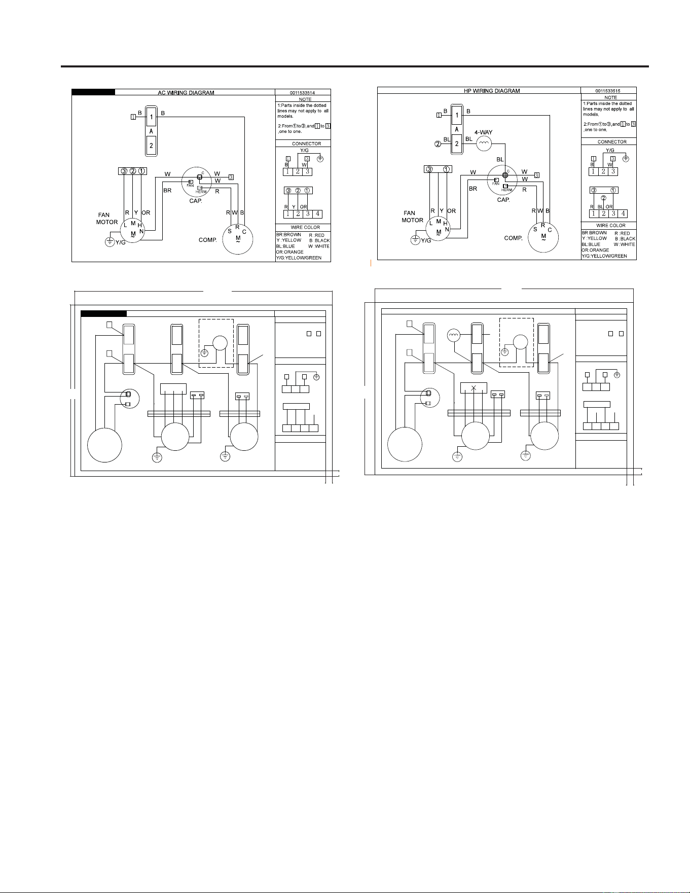
22 49-5000888 Rev. 5
Diagramas Esquemáticos
DIAGRAMAS ESQUEMÁTICOS
AC WIRING DIAGRAM
NOTE
3mm
3mm
WIRE COLOR
CONNECTOR
From
①
to
ĺ
,and to
,one to one.
B
1 3
Y/G
W
1
2
3
4
R
OR
①②③
1
2
3
④
GR
Y
0011526311A
3
1
Y/G:YELLOW/GREEN
B :BLACK
W :WHITE
R :RED
BL:BLUE
Y :YELLOW
OR:ORANGE
BR:BROWN
GR:GREY
CAP.
~
R
C
M
S
COMP.
R
W
W
B
B
B
3
1
W
W
D
W
W
ID FAN
MOTOR
L
M
H
~
M
N
Y/G
CAP.
③①
W
OR
Y
R
BR BL
N
M
~
Y/G
OD FAN
MOTOR
BRBL
GR
W
B
④
GR
C
1
2
GR
W
CAP.
1
2
1
2
W
Y/G
W
B
OPTIONAL
CONDENSATE
PUMP
②
120mm
80mm
3mm
3mm
HP WIRING DIAGRAM
NOTE
WIRE COLOR
CONNECTOR
From
①
to
ĺ
,and to
,one to one.
3
1
B
1 3
Y/G
W
1
2
3
4
R
BL
OR
①
②
③
1
2
3
④
GR
0011526291A
Y/G:YELLOW/GREEN
B :BLACK
W :WHITE
R :RED
BL:BLUE
Y :YELLOW
OR:ORANGE
BR:BROWN
GR:GREY
CAP.
~
R
C
M
S
COMP.
R
W
W
B
B
B
3
1
W
W
D
W
W
ID FAN
MOTOR
L
M
H
~
M
N
Y/G
CAP.
③①
W
OR
Y
R
BR BL
N
M
~
Y/G
OD FAN
MOTOR
BRBL
GR
W
B
④
GR
C
1
2
4-WAY
BL
BL
②
BL
GR
W
CAP.
1
2
1
2
W
Y/G
W
B
OPTIONAL
CONDENSATE
PUMP
120mm
80mm
49-5000888 Rev. 5 23
GARANTÍA LIMITADA
Garantía Limitada del Acondicionador de Aire GE Appliances
Ŷ,QVWDODFLyQHQWUHJDRPDQWHQLPLHQWRLQDGHFXDGRV6L
tiene un problema de instalación o el acondicionador de
aire no posee la capacidad de refrigeración adecuada con
relación al uso deseado, contacte a su vendedor minorista o
LQVWDODGRU8VWHGHVUHVSRQVDEOHGHEULQGDULQVWDODFLRQHVGH
conexión eléctrica adecuadas.
Ŷ)DOODGHOSURGXFWRFRPRUHVXOWDGRGHPRGLILFDFLRQHVVREUHHO
mismo o debido a un uso irrazonable, incluyendo la falta de
mantenimiento razonable o necesario.
Ŷ(OWUDEDMRQHFHVDULRSDUDWUDVODGDUODXQLGDGDXQDXELFDFLyQ
donde esté accesible para que un técnico del servicio o uno
individual pueda brindarle el servicio.
Ŷ5HHPSOD]RGHIXVLEOHVGHODFDVDRUHLQLFLRGHGLV\XQWRUHV
Ŷ'DxRVRFDVLRQDGRVVREUHHOSURGXFWRSRUXQQLYHOGH
suministro de voltaje inadecuado, accidentes, incendios,
inundaciones o catástrofes naturales.
Ŷ'DxRVFRQVHFXHQWHVRLQFLGHQWDOHVFDXVDGRVSRUSRVLEOHV
defectos del acondicionador de aire.
Ŷ'DxRFDXVDGRGHVSXpVGHODHQWUHJD
Qué No Cubrirá GE Appliances:
Esta garantía limitada se extiende al comprador original y cualquier comprador posterior de productos comprados para uso
UHVLGHQFLDOGHQWURGH(VWDGRV8QLGRV6LHOSURGXFWRHVWiVLWXDGRHQXQiUHDTXHQRGLVSRQHGHVHUYLFLRSRUSDUWHGHXQ
proveedor de servicio autorizado de GE Appliances, podría tener que hacerse cargo de los costes de envío o bien podría
solicitársele que lleve el producto a una centro de servicio de GE appliances autorizado para realizar la reparación. En Alaska,
la garantía limitada excluye el costo de envío o las visitas de servicio a su casa.
Algunos estados no permiten la exclusión o las limitaciones de daños incidentales o consecuenciales. Esta garantía limitada da
derechos legales específicos, y usted podría tener otros derechos que variarán de estado a estado. Para saber cuáles son sus
derechos legales, consulte a la oficina de asuntos del consumidor local o la oficina del Attorney General en su localidad.
Garante: GE Appliances, a Haier company
Louisville, KY 40225
7RGRHOVHUYLFLRGHJDUDQWtDGHEHUiVHUSURYLVWRSRUQXHVWURV&HQWURVGH6HUYLFLRGH)DEULFDFLyQRSRUXQWpFQLFRDXWRUL]DGR
del Servicio al Cliente (Customer Care
®
). Para programar una visita del servicio técnico a través de Internet, visítenos en
GEAppliances.com/service, o llámenos al
&XDQGROODPHSDUDVROLFLWDUHOVHUYLFLRWHQJDORVQ~PHURVGHVHULH\PRGHORGLVSRQLEOHV
EXCLUSIÓN DE GARANTÍAS IMPLÍCITAS—Su único y exclusivo derecho es la reparación del producto, tal y
como se indica en esta Garantía limitada. Cualquier garantía implícita, incluyendo las garantías implícitas de
comerciabilidad o adecuación para un fin determinado, están limitadas a dos años o el período de tiempo más
breve permitido por la ley.
Por el período de: GE Appliances Reemplazará:
Dos Años
A partir de la fecha de la
compra original
Cualquier parte del acondicionador de aire que falle debido a defectos en los materiales o en la
IDEULFDFLyQ'XUDQWHHVWDgarantía limitada de dos años, GE Appliances también proporcionará,
sin costo alguno, toda la mano de obra y el servicio relacionado—para reemplazar partes
defectuosas.
Grape aquí su recibo. Se requiere facilitar prueba de la fecha
de compra original para obtener un servicio bajo la garantía.

24 49-5000888 Rev. 5
Soporte para el Consumidor
SOPORTE PARA EL CONSUMIDOR
Sitio Web de GE Appliances
¢'HVHDUHDOL]DUXQDFRQVXOWDRQHFHVLWDD\XGDFRQVXHOHFWURGRPpVWLFR"£,QWHQWHDWUDYpVGHO6LWLR:HEGH*($SSOLDQFHVODV
KRUDVGHOGtDFXDOTXLHUGtDGHODxR8VWHGWDPELpQSXHGHFRPSUDUPiVHOHFWURGRPpVWLFRVPDUDYLOORVRVGH*($SSOLDQFHV\
aprovechar todos nuestros servicios de soporte a través de Internet, diseñados para su conveniencia.
(Q((88GEAppliances.com
Registre su Electrodoméstico
£5HJLVWUHVXHOHFWURGRPpVWLFRQXHYRDWUDYpVGH,QWHUQHWVHJ~QVXFRQYHQLHQFLD8QUHJLVWURSXQWXDOGHVXSURGXFWRSHUPLWLUi
una mejor comunicación y un servicio más puntual de acuerdo con los términos de su garantía, en caso de surgir la necesidad.
7DPELpQSXHGHHQYLDUXQDFDUWDHQODWDUMHWDGHLQVFULSFLyQSUHLPSUHVDTXHVHLQFOX\HFRQHOPDWHULDOHPEDODGR
(Q((88GEAppliances.com/register
Servicio Programado
(Q((88GEAppliances.com/serviceRFRPXQtTXHVHDOGXUDQWHHOKRUDULRGHDWHQFLyQFRPHUFLDO
Garantías Extendidas
Adquiera una garantía extendida de GE Appliances y conozca los descuentos especiales que están disponibles mientras su
garantía aún está vigente. La puede adquirir en cualquier momento a través de Internet. Los servicios de GE Appliances aún
estarán allí cuando su garantía caduque.
(Q((88GEAppliances.com/extended-warrantyRFRPXQtTXHVHDOGXUDQWHHOKRUDULRGHDWHQFLyQFRPHUFLDO
Piezas y Accesorios
Aquellos individuos calificados para realizar el servicio técnico de sus propios electrodomésticos podrán solicitar el envío de
SLH]DVRDFFHVRULRVGLUHFWDPHQWHDVXVKRJDUHVVHDFHSWDQODVWDUMHWDV9,6$0DVWHU&DUG\'LVFRYHU2UGHQHKR\DWUDYpVGH
,QWHUQHWGXUDQWHODVKRUDVWRGRVORVGtDV(Q((88GEApplianceparts.comRGHIRUPDWHOHIyQLFDDOGXUDQWH
el horario de atención comercial.
Las instrucciones que figuran en este manual cubren los procedimientos que serán realizados por cualquier usuario.
Otros servicios técnicos generalmente deben ser derivados a personal calificado del servicio. Se deberá tener cuidado,
ya que una reparación indebida podrá hacer que el funcionamiento no sea seguro.
Contáctenos
Si no se encuentra satisfecho con el servicio que recibió de GE Appliances, comuníquese con nosotros a través de nuestro sitio
Web con todos los detalles, incluyendo su número telefónico, o escriba a:
(Q((88*HQHUDO0DQDJHU&XVWRPHU5HODWLRQV_*($SSOLDQFHV$SSOLDQFH3DUN_/RXLVYLOOH.<
GEAppliances.com/contact