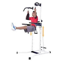
DELUXE MULTI-FUNCTIONAL
POWER TOWER
(with Slide-Adjust Parallel Bars)
PT728/PT730
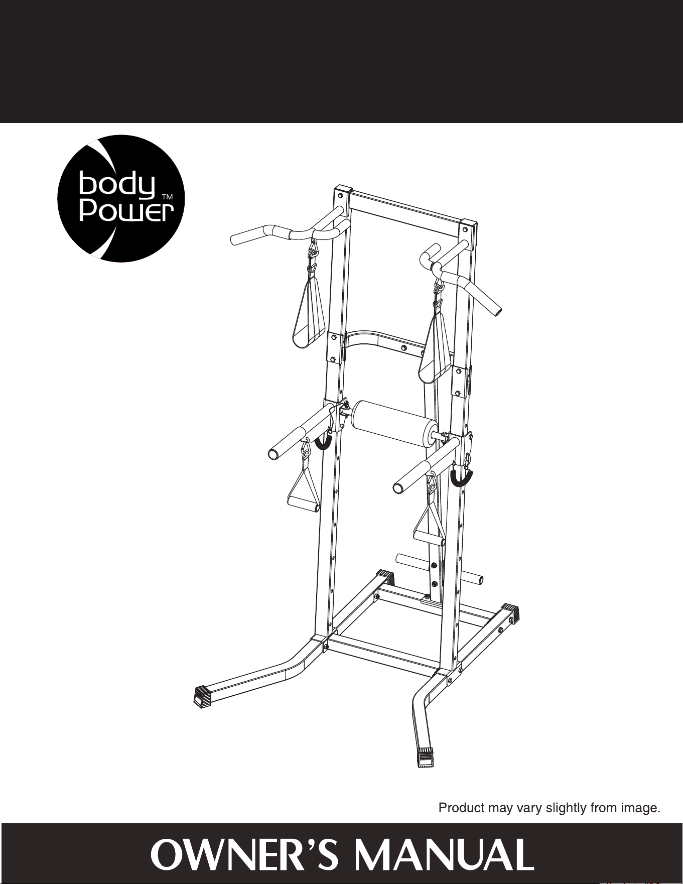
WARNING: SERIOUS INJURIES AND EVEN DEATH CAN OCCUR IF THE PROPER SAFETY PRECAUTIONS ARE NOT FOLLOWED.
The diagram below highlights and reviews many of the important Safety and Warning labels also found
on the unit. Please ensure any user of the unit familiarizes themselves with these Safety and Warning
guidelines before use.
PLEASE KEEP THESE INSTRUCTIONS FOR FUTURE USE & REFERENCE.
DO NOT DISCARD.
Page 1PT728/PT730
1. Thoroughly inspect equipment before each workout. Check all nuts, bolts, screws and pop pins to be in place and fully tightened. Also, if included, check cables for signs
of wear. Replace all worn parts before exercising. Never use the machine if any parts are damaged or missing. Failure to follow these rules may result in serious injury.
2. Keep body, hair and clothing free and clear of all moving parts.
3. Exercise carefully and with caution; you use this product at your own risk. Perform your exercises at a moderate pace; never perform jerky or uncoordinated movement
that may cause injury. It is recommended that you should work out with a partner.
4. Do not allow children or minors to play on or around this equipment. Teenagers using strength equipment should be supervised by an adult.
5. Read and understand all instructions & warnings stated in the Owner's Manual as well as on the equipment before exercising.
6. WARNING: You should consult your physician before starting any exercise regimen. For your own safety, do not begin any exercise program without proper instructions.
7. The equipment is not to be used in a commerical setting.
8. Replace label if damaged,illegible, or removed.
9. This item meets
10. Weight Limit:300 LBS
ASTM F2216 standards for fitness equipment.
The use of this exercise equipment involves a
RISK OF PHYSICAL INJURY as well as property damage, which can be minimized by observing the following guidelines:
W A R N I N G !
!
General Information
Page 2PT728/PT730
Warranty
Body Flex Sports warrants your product for
a period of 1 year for the frame and 90 days
on all parts if the item is used for the intended
purpose, properly maintained and not used
commercially. Any alterations or incorrect
assembly of the product will void this warranty.
Proof of purchase must be presented for any
warranty validation (no exceptions). This
warranty applies to the original purchaser only
and is not transferable.
This warranty does not cover abuse or defects
caused during use, storage or assembly.
During the warranty period, Body Flex Sports
reserves the right to:
a). provide replacement parts to the
purchaser in an effort to repair the item.
b). repair the product returned to our
warehouse (at the purchaser’s cost).
c). replace the product if neither of the two
previously mentioned actions effect repair.
This warranty does not cover normal wear and
tear on upholstery.
Questions
If you have any questions concerning the
assembly of your item or if any parts are
missing, please DO NOT RETURN THE
ITEM TO THE STORE OR CONTACT THE
RETAILER. Our dedicated customer service
staff can help you with any questions you may
have regarding the assembly of this unit and
can also mail you replacement parts.
Customer Support
Customer Support is open 9:00 a.m. to 5:00
p.m. (Pacific Time) Monday through Friday.
Please contact us by any of the following
means.
Body Flex Sports, Inc.
21717 Ferrero Parkway, Walnut, CA 91789
Telephone: (888) 266 - 6789
Fax: (909) 598 - 6707
Email: info@bodyflexsports.com
Safety
Before you undertake any exercise program,
please be sure to consult with your doctor.
Frequent strenuous exercise should be
approved by your doctor and proper use
of your product is essential. Excessive or incorrect
training may result to health injuries. Please read
this manual carefully before commencing the
assembly of your product or starting to exercise.
• Please keep all children away from this item
when in use. Do not allow children to climb or
play on them when they are not in use.
• Supervise teenagers while they use this unit.
• For your own safety, always ensure that there
is at least 3 feet of free space in all directions
around your product while you are exercising.
• Regularly check to see that all nuts, bolts and
fittings are securely tightened. Periodically
check all moving parts for obvious signs of
wear or damage.
• Clean only with a damp cloth, do not use
solvent cleaners. If you are in any doubt, do
not use your product; contact CUSTOMER
SUPPORT.
• Before use, always ensure that your product
is positioned on a solid, flat surface. If
necessary, use a rubber mat underneath to
reduce the possibility of slipping.
•
Always wear appropriate clothing and
footwear such as training shoes when
exercising. Do not wear loose clothing that
could become caught in moving parts during
exercise.
• Do not use this unit if it is not functioning
properly or if it is not fully assembled.
• Do not use this unit for commercial purposes.
This unit is for home use only.
Storage and Use
Your product is intended for use in clean
dry conditions. You should avoid storage in
excessively cold or damp places as this may
lead to corrosion and other related problems.
Weight Limit
Your product is suitable for users weighing:
300 pounds or less.
• Before use, you must read and understand all
instructions & warnings stated in this Owner’s
Manual as well as posted on the equipment.
• It is the facility owner’s responsibility to properly
instruct users on the proper operation of the
equipment and to warn them of the potential
hazards.
• If at any time during exercise you feel faint, dizzy
or experience pain, stop and consult your
physician.
Assembling Tools
- Ruler with both metric and English measurements
- 2 x Adjustable Wrenches
- 1 x Philips (”Crosshead”) Screw Driver
•
Any adjustment devices that could interfere with
the user's movement on this unit should not be
left projecting.
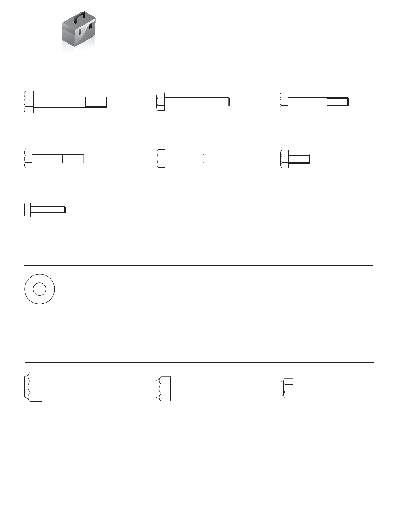
Hardware List
The following hardware is used to assemble your unit. Please take a moment to familiarize yourself with these
items. Please note some of this hardware is already pre-assembled on the machine. Do not be alarmed if you
see parts on this page that are not included in your hardware packet
#33. Washer (M10)
[10 pieces]
Nut
BOLT
#23. Hex Bolt (M12x85 mm)
[2 pieces]
#24. Hex Bolt (M10x75 mm)
[4 pieces]
#25. Hex Bolt (M10x70 mm)
[6 pieces]
Washer
Page 3PT728/PT730
#26. Hex Bolt (M10x60 mm)
[6 pieces]
#27. Hex Bolt (M10x45 mm)
[4 pieces]
#28. Hex Bolt (M10x25 mm)
[2 pieces]
#29. Hex Bolt (M8x40 mm)
[1 piece]
#30. Nylon Nut (M12)
[2 pieces]
#31. Nylon Nut (M10)
[20 pieces]
#32. Nylon Nut (M8)
[1 piece]

Parts Listing
The following parts list describes all of the parts illustrated on the
exploded diagram on the following page. Please note, most of
these parts are already pre-assembled on your unit.
Page 4PT728/PT730
# Description # Description
01 Left Base Tube 23 Hex Bolt (M12x85 mm)
02 Right Base Tube 24 Hex Bolt (M10x75 mm)
03 Front Base 25 Hex Bolt (M10x70 mm)
04 Rear Base 26 Hex Bolt (M10x60 mm)
05 Left/Right Upright 27 Hex Bolt (M10x45 mm)
06 Supporting Tube 28 Hex Bolt (M10x25 mm)
07 Foot Tube 29 Hex Bolt (M8x40 mm)
08 Top Upright 30 Nylon Nut (M12)
09 Center Cross Tube 31 Nylon Nut (M10)
10 Left VKR Parallel Bar 32 Nylon Nut (M8)
11 Right VKR Parallel Bar 33 Washer (M10)
12 Foam Roller Tube 34 Square End Cap (50 mm)
13 Left Upper Handle Bar 35 R
ound End Cap (38 mm)
14 Right Upper Handle Bar 36 Round End Cap (32 mm)
15 Reinforcement Plate (Rear) 37 Round End Cap (25 mm)
16 Reinforcement Plate (Front) 38 Rectangular End Cap (40x60 mm)
17 Bushing 39 Foam Roller
18 Pop-pin 40 Foam
19 Pop-pin 41 Foam
20 Hook 42 Foam
21 Sling Strap 43 Foam
22 Hand Strap
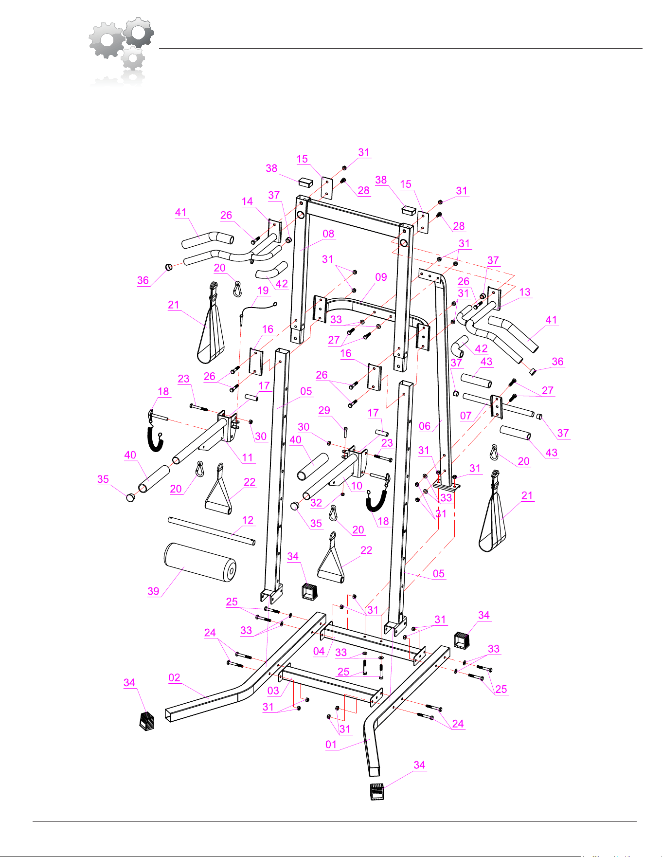
Exploded Diagram
The following diagram is provided to help you familiarize yourself with the parts and
hardware that will be used during the assembly process. Please note that not all of the
parts and hardware you see here will be used while you are assembling the machine
because some of these items are already pre-installed. Please continue to the next
page to begin the assembly process and use this page only as a reference guide for
parts and hardware.
Page 5PT728/PT730
Assembly Instructions
PT728/PT730
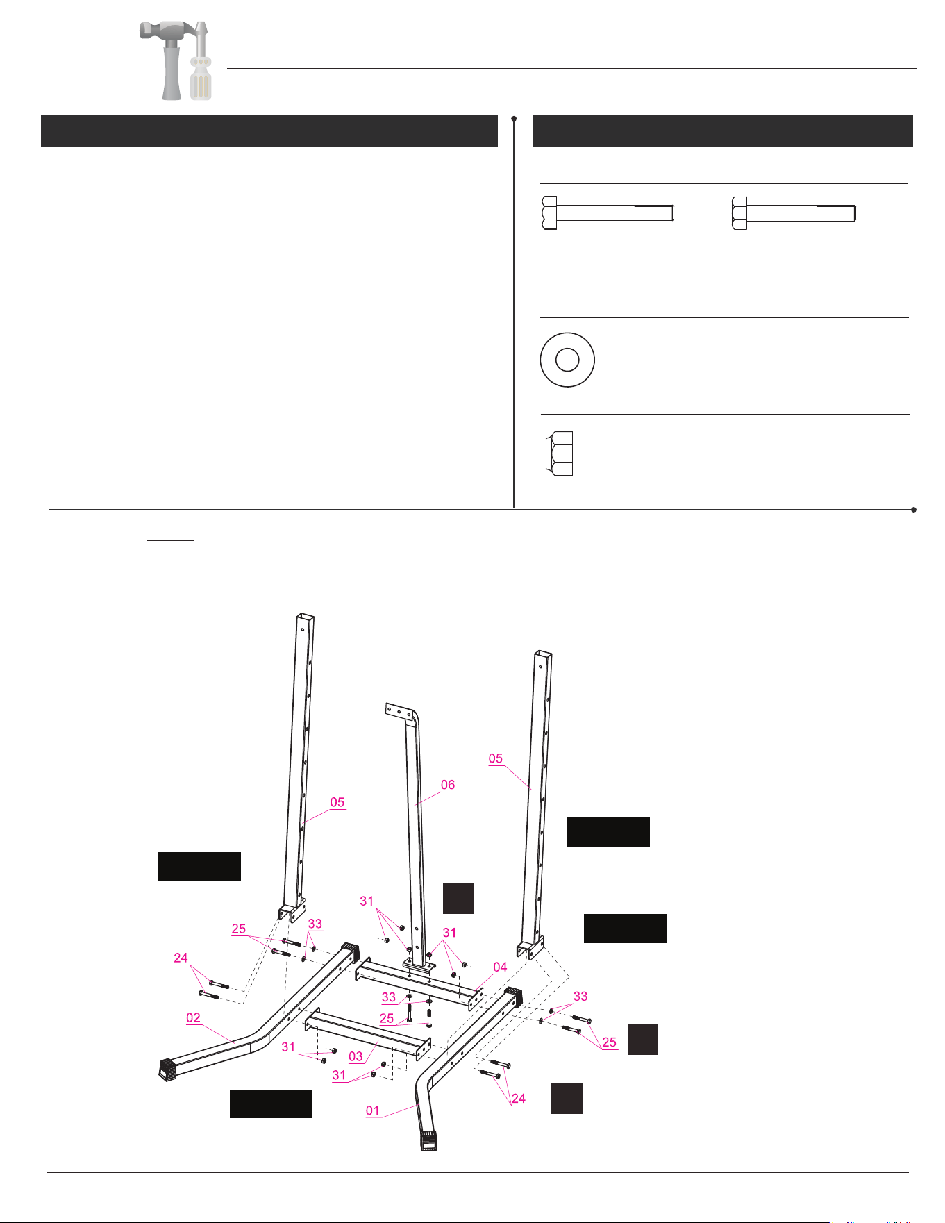
B.) Align and attach the Rear Base (#04) to the Left Base Tube
(#01) as illustrated in the diagram. Insert two Hex Bolts (#25)
through two Washers (#33) followed by the Left Base Tube (#01)
and Rear Base (#04); secure them together using two Nylon Nuts
(#31).
Page 6
NOTE:
C.) Align and attach the Left Upright (#05) to the Left Base Tube
(#01). Next, align and attach the Front Base (#03) to the Left Base
Tube (#01) as illustrated in the diagram. Insert two Hex Bolts (#24)
through the Left Upright (#05) followed by the Left Base Tube
(#01) and Front Base (#03) secure them together using two Nylon
Nuts (#31).
Repeat STEP B and STEP C on the other side.
Assembly Step 1 Hardware Required
A
A.) With the help of an assistant, align and attach the Rear Base
(#04) to the Supporting Tube (#06) as illustrated in the diagram.
Insert two Hex Bolts (#25) through two Washers (#33) followed
by the Rear Base (#04) and the Supporting Tube (#06); secure
them together using two Nylon Nuts (#31).
#33. Washer (M10)
[6 pieces]
Nut
BOLT
#24. Hex Bolt (M10x75 mm)
[4 pieces]
#25. Hex Bolt (M10x70 mm)
[6 pieces]
Washer
#31. Nylon Nut (M10)
[10 pieces]
To avoid misalignment due to over-tightening, please do not use a wrench at this time.
Hand-tightening for now will help ensure easy assembly. Wrench-tightening should
be performed after all parts are assembled to ensure all nuts, bolts, and parts are tightly secured before use.
C
B
LEFT
RIGHT
FRONT
REAR
*
*
*
Drawings are rotated 180 degrees
for maximum clarity in the assembly
process. Hence, “left” and “right”
sides may appear to be reversed.
A
Assembly Instructions
Page 7
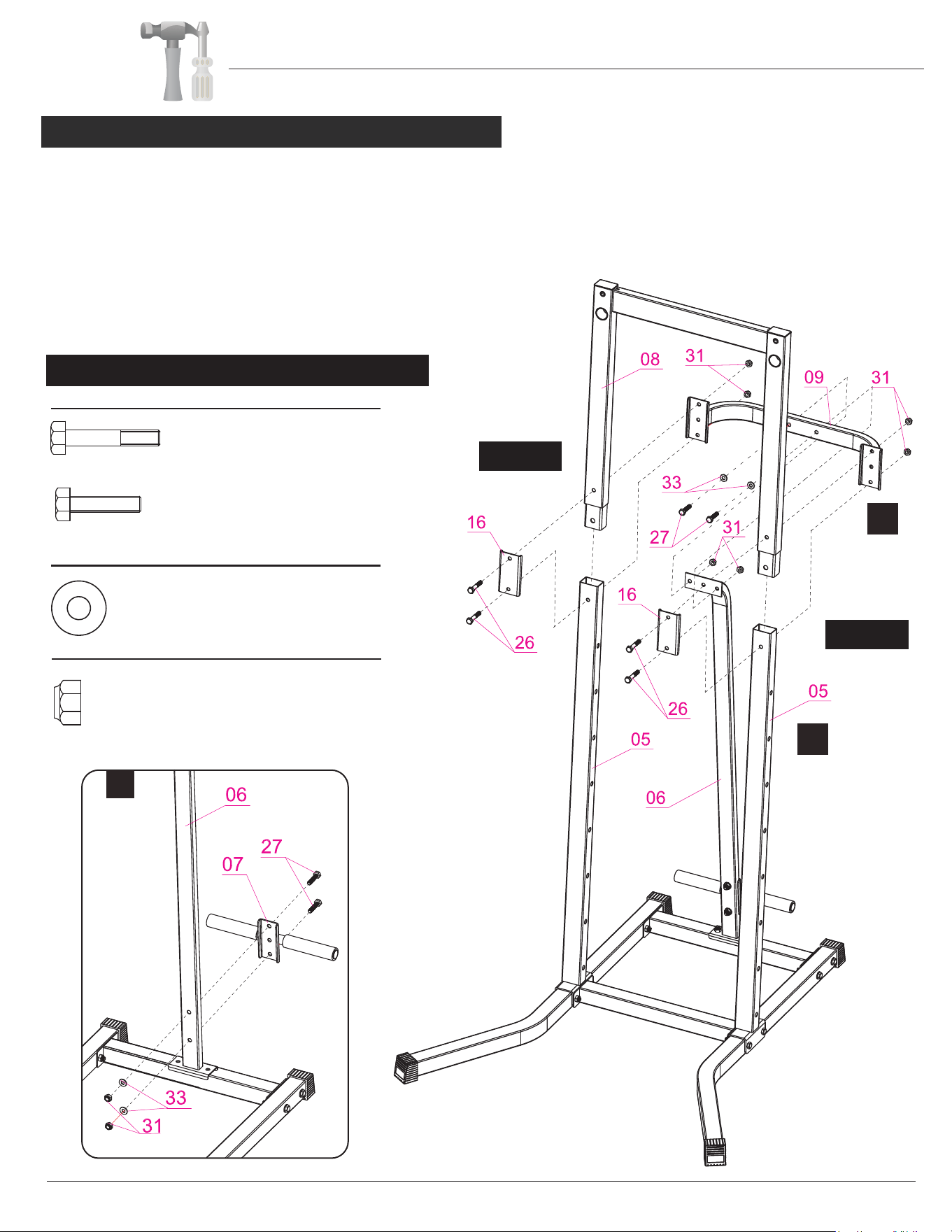
Assembly Step 2
PT728/PT730
LEFT
RIGHT
C
B
A.) With the help of an assistant, attach the Foot Tube (#07) to the Supporting Tube (#06), secure them together using two Hex
Bolts (#27) two Washers (#33) and two Nylon Nuts (#31).
B.) Attach the Top Upright (#08) onto the Left/Right Uprights (#05). Attach the Center Cross Tube (#09) to the Top Upright
(#08) and Left/Right Uprights (#0). Secure them together using two Reinforcement Plates (Front) (#16) , four Hex
Bolts (#26) and four Nylon Nuts (#31) -- all as shown and oriented in illustration.
C.) Attach the Supporting Tube (#06) to the Center Cross Tube
(#09). Secure them together using two Hex Bolts (#27), two
Washers (#33) and two Nylon Nuts (#31).
A
Hardware Required
#33. Washer (M10)
[4 pieces]
Nut
BOLT
Washer
#26. Hex Bolt (M10x60 mm)
[4 pieces]
#27. Hex Bolt (M10x45 mm)
[4 pieces]
#31. Nylon Nut (M10)
[8 pieces]
Page 8
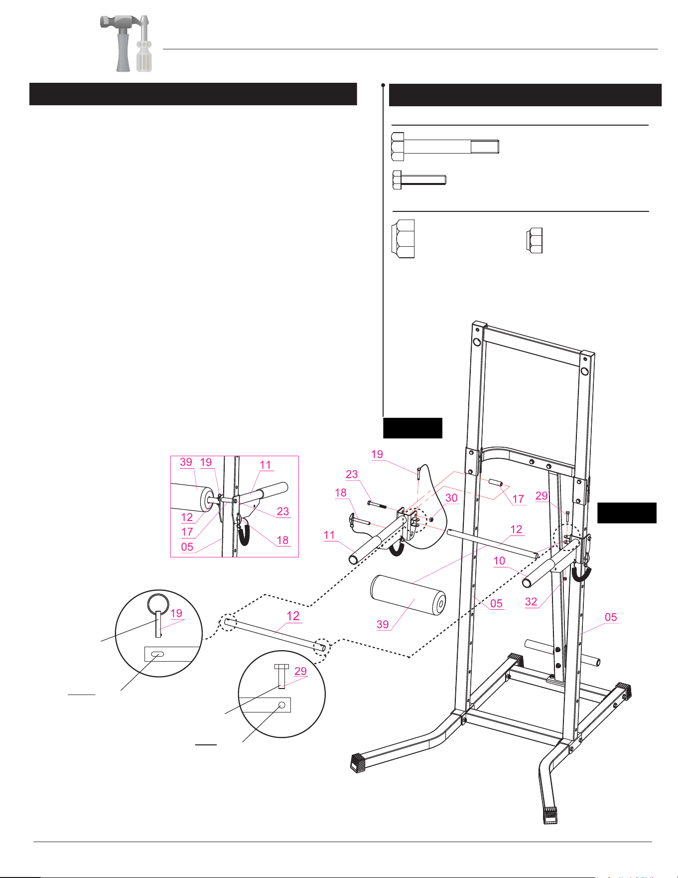
With the help of an assistant, attach the Right VKR Parallel Bar (#11)
to the Right Upright (#05) ; secure them together by using one
Pop-pin (#18) inserted through lower hole of the bracket on Right VKR
Parallel Bar (#11) and top hole on Right Upright (#05). Next, continue
securing them together by using one Hex Bolt (#23) inserted through
upper hole of the bracket on Right VKR Parallel Bar (#11), one
Bushing (#17), the other side of the bracket on Right VKR Parallel
Bar (#11) and secure with one Nylon Nut (#30).
Repeat this process on the other side.
Slide on the Foam Roller (#39) onto the Foam Roller Tube (#12).
Insert the Foam Roller Tube (#12) into the two small brackets on the
Left VKR Parallel Bar (#10) and Right VKR Parallel Bar (#11).
(Please ensure that the CIRCLE-shaped hole is on the left side,
and the OVAL-shaped hole is on the right side.)
On the left side (CIRCLE-shaped hole), secure using one Hex Bolt
(#29) and one Nylon Nut (#32).
NOTE: Please do not over-tigthen the Hex Bolt (#29) so that it is
easier for you to slide-adjust the height.
On the right side (OVAL-shaped hole), secure by inserting one
Pop-pin (#19).
PT728/PT730
NOTE:
For easier assembly, only hand-tighten the Nuts
& Bolts for now. After all parts have been put in
place, then proceed to tighten with a wrench.
Assembly Step 3
Hardware Required
Assembly Instructions
RIGHT
(RIGHT Side:
OVAL-shaped hole)
(LEFT Side:
CIRCLE-shaped hole)
Pop-pin (#19)
Nylon Nut (#32)
LEFT
Nut
BOLT
#23. Hex Bolt (M12x85 mm)
[2 pieces]
#29. Hex Bolt (M8x40 mm)
[1 piece]
#30. Nylon Nut (M12)
[2 pieces]
#32. Nylon Nut (M8)
[1 piece]
(VIEW OF CORRECTLY ASSEMBLED
RIGHT SIDE FROM REAR PERSPECTIVE)
Hardware Required
Nut
BOLT
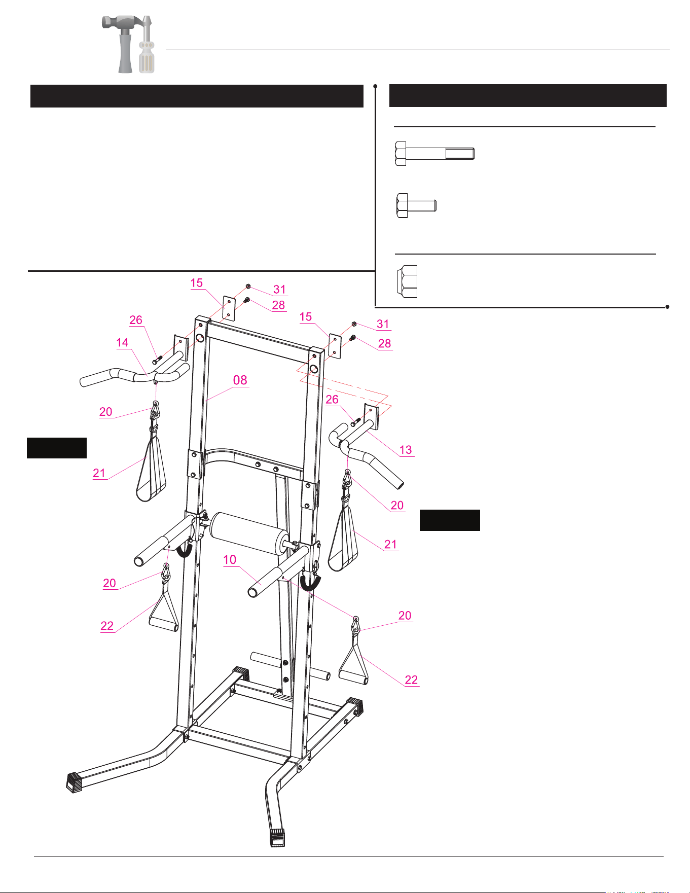
#26. Hex Bolt (M10x60 mm)
[2 pieces]
#28. Hex Bolt (M10x25 mm)
[2 pieces]
#31. Nylon Nut (M10)
[2 pieces]
Assembly Step 4
Page 9
Assembly Instructions
PT728/PT730
With the help of an assistant, attach the Left Upper Handle Bar
(#13) to the left side of the Top Upright (#08). Secure them together
using one Reinforcement Plate (Rear) (#15), one Hex Bolt (#28),
Hex Bolt (#26) and one Nylon Nut (#31).
Attach the Sling Strap (#21) to the Left Upper Handle Bar (#13)
with a Hook (#20).
Repeat this process on the opposite side.
Attach the Hand Strap (#22) to the Left VKR Handle Bar (#10)
with a Hook (#20).
LEFT
RIGHT
The assembly process is now complete. However, for your own safety,
please make sure to read this entire Owner’s Manual which includes
safety instructions and warnings, as well as any safety/warning labels
affixed to the product before use.
For your safety, please visually and functionally inspect and test the unit
after assembly is complete.
one
Page 10PT728/PT730
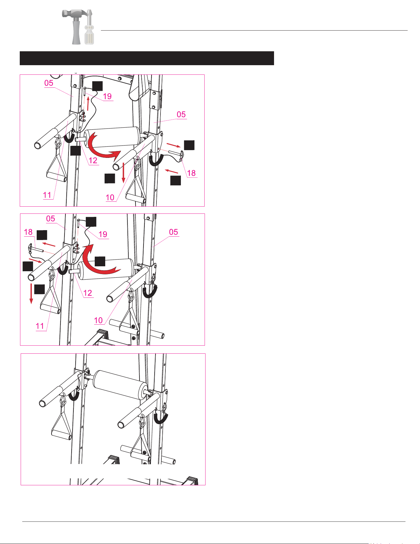
How to Adjust the Height of Slide-Adjust Parallel Bars
Assembly Instructions
A.) On (#11):
UN-PIN (#19).
C.) On (#10):
UN-PIN (#18).
B.) UN-HINGE (#12).
D.) SLIDE AND ADJUST (#10) to your desired hole
height setting.
E.) RE-INSERT (#18) to secure (#10) to your desired
hole height setting
H.)
RE-INSERT (#18) to secure (#11) to the matching
hole height setting.
I.) RE-HINGE/RETURN (#12) to align with the holes
on the bracket (#11).
J.) RE-INSERT (#19) through both the bracket on
(#11) and (#12).
Note: To avoid serious injury and ensure correct usage, always
make sure (#10) and (#11) are set to the same matching and
corresponding hole height setting.
H
CORRECT ASSEMBLY REFERENCE
F.) On (#11):
UN-PIN (#18).
G.) SLIDE AND ADJUST (#11) to the same matching
and corresponding hole height setting that you set
in “D.” above.
A
B
C
D
E
F
G
I
J

• Make sure all nuts, bolts, and screws are tightened prior to use.
• Be sure that all adjustment locking devices and safety devices (if present) are properly engaged
prior to use!
• Never over-tighten the above-mentioned devices and parts to avoid damage to the unit.
• Check for loose parts and components and make proper adjustments prior to use.
• Check to see if there are any tears or bends in the welding or metal prior to use. If tears or bends
are found, do NOT use the unit and contact our CUSTOMER SUPPORT.
• Extreme care must be taken to not allow your feet, fingers, hair, clothing, and/or any loose items to be
snagged into any portion of the unit when in use. Failure to follow these instructions could result in serious
injury.
Safety & Maintenance
SAFETY & WARNINGS
• To avoid rust or corrosion to the metal parts caused by moisture and sweat, we advise wiping and drying
the unit with a dry absorbent towel after each workout session.
• Do not use solvent cleaners. If you are in
any doubt, do not use your cleansing product;
contact CUST
OMER SUPPORT.
• For any replacement warning labels, please con
tact our CUSTOMER SUPPORT at (888) 266-6789
or (909) 598-9876, or mail in a written request to: Body Flex Sports, Inc. 21717 Ferrero Parkway,
Walnut, CA 91789. More detailed informatio
n about how to reach our CUSTOMER SUPPORT may
be found on Page 1 of the Owner’s Manual under the “CUSTOMER SUPPORT” section.
• The specific Parts on your unit which may see possible signs of wear after prolonged use are listed as
follows (please check these parts before each use):
Right Upper Handle Bar (#14), Left Upper Handle Bar (#13), Left/Right VKR Handle Bar (#10/11).
• Please review all safety instructions and warni
ngs in this entire Owner’s Manual, as well as any
safety/warning labels affixed to the product before use.
M a i n t e n a n c e & C a r e
Page 11PT728/PT730
Before use, you must read and understand all instructions & warning stated in this Owner's Manual as well as
posted on the equipment.
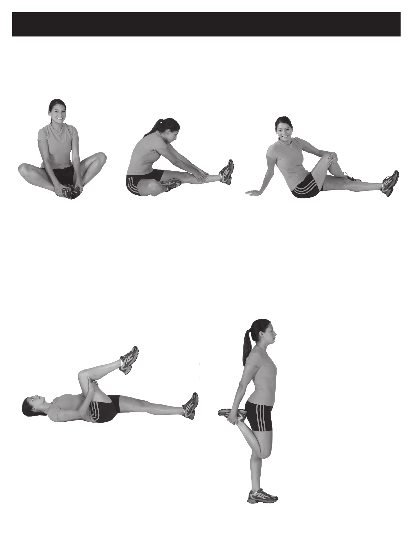
Warm-Up Instructions
Groin Stretch
1. Sit with your knees flexed
and soles of feet together.
2. Hold your ankles and bend
at your hips (keep your
back straight) as you press
your knees toward the
floor with your elbows.
Hamstring Stretch
1. Sit with your left leg extended and bend your right
leg at the knee as you place the sole of your right foot
against the inner thigh of your extended leg.
2. Flex the foot of your extended leg (toes pointed
toward ceiling) and gently bend forward from your
hips; keep your back straight.
3. Reach your hands on your extended leg as far as pos-
sible and then switch legs and repeat.
Trunk Twister
1. Sit with your leg extended and
bend your right knee as you cross
your right leg over your left leg.
Your right foot should be flat on the
floor alongside your left knee.
2. Place your left arm on the outside
of your right leg and pull against
that leg while twisting your trunk
as far as possible to the right. Place
your right hand on the floor behind
your buttocks. Reverse leg posi-
tions and repeat.
Hip Stretch
1. Lie on your back and raise your right leg as you clasp both hands
under the back of the knee. Keep your left leg straight.
2. Gently pull your right leg toward your trunk without raising your
upper body. Switch leg positions and repeat.
The following flexibility exercises are provided to you as a means to prevent injury while you are exercising. A
proper warm-up routine decreases the chance of injuring your muscles while you are exercising. Please take the
time to do these flexibility exercises before and after each time you exercise.
Quadriceps Stretch
1. Stand on your left leg and hold onto
a support with your left hand.
2. Flex your right leg behind you, grasp
your ankle or foot with your right
hand and pull your foot toward your
buttocks. Keep your back straight
and right knee pointed down. Repeat
on the other leg.
Page 12PT728/PT730
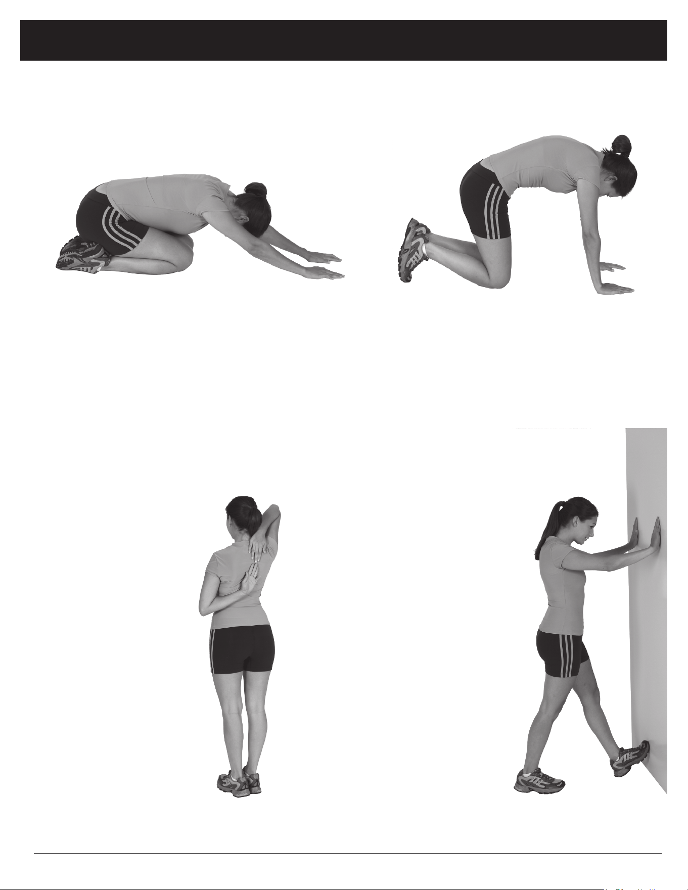
Trunk Flexion, Prone
1. Assume the depicted position on your hands and knees. Stretch your hands out in front of you and then slowly start to pull
them back in toward your body as you tuck your chin and arch your back upward.
2. Return to the starting position slowly.
Shoulder Stretch
1. Bring your right hand over
your right shoulder to the
upper back and bring your
left hand under your left
shoulder to the upper back.
2. Try to reach your finger-
tips. If you are not able to
reach your fingertips, use
a towel as an extension of
your hands and gently pull
one hand toward the other.
Reverse arm positions and
repeat.
Calf Stretch
1. Place both hands against
a wall to aid your balance.
Press the ball of your left foot
against the wall and keep the
heel of the same foot rested
on the floor (make sure your
left knee is bent).
2. Slowly start to straighten your
left knee and you will feel
the muscles in your left calf
stretch. Switch leg positions
and repeat.
Warm-Up Instructions
Page 13PT728/PT730

This page intentionally left blank

Thanks for choosing
PT728/PT730
Store Location:
Version: 08-17-2015
Hardware Required
