92-23577-136-00
[ ] INDICATES METRIC CONVERSIONS
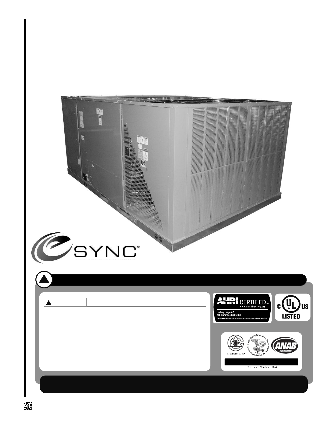
INSTALLATION INSTRUCTIONS
FOR THE RHEEM H2AC ROOFTOP UNIT
FEATURING eSYNC INTEGRATION TECHNOLOGY
RLHL-D SERIES 15 TON [52.8 kW]
ASHRAE 90.1 2007 COMPLIANT, WITH CLEAR CONTROL
RECOGNIZE THIS SYMBOL AS AN INDICATION OF IMPORTANT SAFETY INFORMATION!
!
DO NOT DESTROY THIS MANUAL
PLEASE READ CAREFULLY AND KEEP IN A SAFE PLACE FOR FUTURE REFERENCE BY A SERVICEMAN
WARNING
!
THESE INSTRUCTIONS ARE INTENDED AS AN AID TO
QUALIFIED, LICENSED SERVICE PERSONNEL FOR PROPER
INSTALLATION, ADJUSTMENT AND OPERATION OF THIS
UNIT. READ THESE INSTRUCTIONS THOROUGHLY BEFORE
ATTEMPTING INSTALLATION OR OPERATION. FAILURE TO
FOLLOW THESE INSTRUCTIONS MAY RESULT IN IMPROPER
INSTALLATION, ADJUSTMENT, SERVICE OR MAINTENANCE
POSSIBLY RESULTING IN FIRE, ELECTRICAL SHOCK, PROP-
ERTY DAMAGE, PERSONAL INJURY OR DEATH.
ISO 9001:2008
WITH H2AC TECHNOLOGY

2
I. TABLE OF CONTENTS
Table of Contents . . . . . . . . . . . . . . . . . . . . . . . . . . . . . . . . . . . . . . . . . . . . . . 2
Introduction . . . . . . . . . . . . . . . . . . . . . . . . . . . . . . . . . . . . . . . . . . . . . . . . . . 3
Checking Product Received. . . . . . . . . . . . . . . . . . . . . . . . . . . . . . . . . . . . . . 3
Equipment Protection. . . . . . . . . . . . . . . . . . . . . . . . . . . . . . . . . . . . . . . . . . . 3
Specifications . . . . . . . . . . . . . . . . . . . . . . . . . . . . . . . . . . . . . . . . . . . . . . . . . 3
General . . . . . . . . . . . . . . . . . . . . . . . . . . . . . . . . . . . . . . . . . . . . . . . . . . . 3
Major Components. . . . . . . . . . . . . . . . . . . . . . . . . . . . . . . . . . . . . . . . . . . 4
R-410A Refrigerant . . . . . . . . . . . . . . . . . . . . . . . . . . . . . . . . . . . . . . . . . . 4
Unit Dimensions . . . . . . . . . . . . . . . . . . . . . . . . . . . . . . . . . . . . . . . . . . . . . 5-6
General Data . . . . . . . . . . . . . . . . . . . . . . . . . . . . . . . . . . . . . . . . . . . . . . . . . 7
Electrical Data . . . . . . . . . . . . . . . . . . . . . . . . . . . . . . . . . . . . . . . . . . . . . . . . 8
Gross Water Heating Capacity . . . . . . . . . . . . . . . . . . . . . . . . . . . . . . . . . . . 9
Installation . . . . . . . . . . . . . . . . . . . . . . . . . . . . . . . . . . . . . . . . . . . . . . . . . . 10
General . . . . . . . . . . . . . . . . . . . . . . . . . . . . . . . . . . . . . . . . . . . . . . . . . . 10
Pre-Installation Check Points. . . . . . . . . . . . . . . . . . . . . . . . . . . . . . . . 10
Location . . . . . . . . . . . . . . . . . . . . . . . . . . . . . . . . . . . . . . . . . . . . . . . . 10
H2AC Rooftop Unit Special Consideration. . . . . . . . . . . . . . . . . . . . . . . . 10
Clearances . . . . . . . . . . . . . . . . . . . . . . . . . . . . . . . . . . . . . . . . . . . . . . . . 11
Rooftop Installation. . . . . . . . . . . . . . . . . . . . . . . . . . . . . . . . . . . . . . . . . . 11
Ductwork . . . . . . . . . . . . . . . . . . . . . . . . . . . . . . . . . . . . . . . . . . . . . . . . . . . 12
Filters . . . . . . . . . . . . . . . . . . . . . . . . . . . . . . . . . . . . . . . . . . . . . . . . . . . . . . 12
Condensate Drain . . . . . . . . . . . . . . . . . . . . . . . . . . . . . . . . . . . . . . . . . . . . 12
Electrical Wiring . . . . . . . . . . . . . . . . . . . . . . . . . . . . . . . . . . . . . . . . . . . . . . 13
Power Wiring . . . . . . . . . . . . . . . . . . . . . . . . . . . . . . . . . . . . . . . . . . . . . . 13
Control Wiring . . . . . . . . . . . . . . . . . . . . . . . . . . . . . . . . . . . . . . . . . . . . . 14
Internal Wiring . . . . . . . . . . . . . . . . . . . . . . . . . . . . . . . . . . . . . . . . . . . . . 14
Thermostat . . . . . . . . . . . . . . . . . . . . . . . . . . . . . . . . . . . . . . . . . . . . . . . . 14
Indoor Air Flow Data . . . . . . . . . . . . . . . . . . . . . . . . . . . . . . . . . . . . . . . . . . 15
Crankcase Heat . . . . . . . . . . . . . . . . . . . . . . . . . . . . . . . . . . . . . . . . . . . . . . 15
Airflow Performance Tables . . . . . . . . . . . . . . . . . . . . . . . . . . . . . . . . . . . . . 16
Water Connections and Start Up for Potable Water Heating . . . . . . . . . . . 17
Hybrid Water Connection Diagram . . . . . . . . . . . . . . . . . . . . . . . . . . . . . . . 18
Calculating Tubing . . . . . . . . . . . . . . . . . . . . . . . . . . . . . . . . . . . . . . . . . . . . 19
Lime Scale Flushing. . . . . . . . . . . . . . . . . . . . . . . . . . . . . . . . . . . . . . . . . . . 22
Pre-Start Check . . . . . . . . . . . . . . . . . . . . . . . . . . . . . . . . . . . . . . . . . . . . . . 22
Startup . . . . . . . . . . . . . . . . . . . . . . . . . . . . . . . . . . . . . . . . . . . . . . . . . . . . . 22
Operation . . . . . . . . . . . . . . . . . . . . . . . . . . . . . . . . . . . . . . . . . . . . . . . . . . . 23
Cooling Mode. . . . . . . . . . . . . . . . . . . . . . . . . . . . . . . . . . . . . . . . . . . . . . 23
Water Heating Mode (H2AC Sequence of Operation) . . . . . . . . . . . . . . . 23
Faults/Lockouts/Misc.. . . . . . . . . . . . . . . . . . . . . . . . . . . . . . . . . . . . . . . . 24
Heating Mode. . . . . . . . . . . . . . . . . . . . . . . . . . . . . . . . . . . . . . . . . . . . . . 30
Auxiliary Heat. . . . . . . . . . . . . . . . . . . . . . . . . . . . . . . . . . . . . . . . . . . . . . . . 30
Heater Kit Characteristics . . . . . . . . . . . . . . . . . . . . . . . . . . . . . . . . . . . . . . 31
Troubleshooting Chart . . . . . . . . . . . . . . . . . . . . . . . . . . . . . . . . . . . . . . 32-33
Wiring Diagrams . . . . . . . . . . . . . . . . . . . . . . . . . . . . . . . . . . . . . . . . . . . 34-37
Charge Chart . . . . . . . . . . . . . . . . . . . . . . . . . . . . . . . . . . . . . . . . . . . . . . . . 38

II. INTRODUCTION
This booklet contains the installation and operating instructions for your air condition-
er. There are a few precautions that should be taken to derive maximum satisfaction
from it. Improper installation can result in unsatisfactory operation or dangerous condi-
tions.
Read this booklet and any instructions packaged with separate equipment required to
make up the system prior to installation. Give this booklet to the owner and explain its
provisions. The owner should retain this booklet for future reference.
III. CHECKING PRODUCT RECEIVED
Upon receiving the unit, inspect it for any damage from shipment. Claims for damage,
either shipping or concealed, should be filed immediately with the shipping company.
Check the unit model number, heating size, electrical characteristics, and accessories
to determine if they are correct.
IV. EQUIPMENT PROTECTION FROM THE
ENVIRONMENT
The metal parts of this unit may be subject to rust or deterioration in adverse environ-
mental conditions. This oxidation could shorten the equipment’s useful life. Salt spray,
fog or mist in seacoast areas, sulphur or chlorine from lawn watering systems, and var-
ious chemical contaminants from industries such as paper mills and petroleum refiner-
ies are especially corrosive.
If the unit is to be installed in an area where contaminants are likely to be a prob-
lem, special attention should be given to the equipment location and exposure.
1. Avoid having lawn sprinkler heads spray direction on the unit cabinet.
2. In coastal areas, locate the unit on the side of the building away from the water-
front.
3. Shielding provided by a fence or shrubs may give some protection.
Regular maintenance will reduce the buildup of contaminants and help to pro-
tect the unit’s finish.
1. Frequent washing of the cabinet, fan blade and coil with fresh water will remove
most of the salt or other contaminants that build up on the unit.
2. Regular cleaning and waxing of the cabinet with a good automobile polish will pro-
vide some protection.
3. A good liquid cleaner may be used several times a year to remove matter that will
not wash off with water.
Several different types of protective coatings are offered in some areas. These coat-
ings may provide some benefit, but the effectiveness of such coating materials cannot
be verified by the equipment manufacturer.
The best protection is frequent cleaning, maintenance and minimal exposure to
contaminants.
V. SPECIFICATIONS
A. GENERAL
The H2AC Rooftop Unit with optional Electric Heat is available with a Cooling capaci-
ty of 15 nominal tons and optional 20, 40, 60 or 75 kW electric heat.
Potable water heating capacities range from approximately 117,000 BTUH to
145,000 BTUH depending on water temperature, indoor air temperatures, and indoor
CFM.
Units are designed for downflow-only supply and return air and are weatherized and
intended for outdoor installation.
Since the H
2AC Rooftop Unit only functions during the cooling mode, the unit should
be installed to serve the area of the structure having the largest cooling run-time
load, for instance the kitchen area of the restaurant, in order to provide the greatest
water heating and energy saving benefits.
3
PROPOSITION 65: THIS APPLIANCE
CONTAINS FIBERGLASS INSULA-
TION. RESPIRABLE PARTICLES OF
FIBERGLASS ARE KNOWN TO THE
STATE OF CALIFORNIA TO CAUSE
CANCER.
▲WARNING
!
DISCONNECT ALL POWER TO THE
UNIT BEFORE STARTING MAINTE-
NANCE. FAILURE TO DO SO CAN
RESULT IN SEVERE ELECTRICAL
SHOCK OR DEATH.
▲WARNING
!
THE MANUFACTURER’S WARRANTY
DOES NOT COVER ANY DAMAGE OR
DEFECT TO THE AIR CONDITIONER
CAUSED BY THE ATTACHMENT OR
USE OF ANY COMPONENTS, ACCES-
SORIES OR DEVICES (OTHER THAN
THOSE AUTHORIZED BY THE MANU-
FACTURER) INTO, ONTO OR IN CON-
JUNCTION WITH THE AIR CONDI-
TIONER. YOU SHOULD BE AWARE
THAT THE USE OF UNAUTHORIZED
COMPONENTS, ACCESSORIES OR
DEVICES MAY ADVERSELY AFFECT
THE OPERATION OF THE AIR CONDI-
TIONER AND MAY ALSO ENDANGER
LIFE AND PROPERTY. THE MANUFAC-
TURER DISCLAIMS ANY RESPONSI-
BILITY FOR SUCH LOSS OR INJURY
RESULTING FROM THE USE OF SUCH
UNAUTHORIZED COMPONENTS,
ACCESSORIES OR DEVICES.
▲WARNING
!
The information on the rating plate is in compliance with the FTC and DOE rating for
single phase units. The following information is for three phase units which are not
covered under the DOE certification program.
1. The efficiency rating of this unit is a product thermal efficiency rating determined
under continuous operating conditions independent of any installed system.
B. MAJOR COMPONENTS
The unit includes a hermetically-sealed refrigerating system (consisting of a com-
pressor, evaporator coil with thermal expansion valve), a circulation air blower, a con-
denser fan, a refrigerant to air heat exchanger assembly, a refrigerant to water heat
exchanger assembly, 3-way valve, two solenoid valves, and all necessary internal
electrical wiring. The cooling system of these units is factory-evacuated, charged and
performance tested. Refrigerant amount and type are indicated on rating plate.
C. R-410A REFRIGERANT
All units are factory charged with R-410A refrigerant.
1. Specification of R-410A:
Application: R-410A is not a drop-in replacement for R-22
; equipment designs
must accommodate its higher pressures. It cannot be retrofitted into R-22 units.
Pressure: The pressure of R-410A is approximately 60% (1.6 times) greater than
R-22. Recovery and recycle equipment, pumps, hoses and the like need to have
design pressure ratings appropriate for R-410A. Manifold sets need to range up to 800
psig high-side and 250 psig low-side with a 550 psig low-side retard. Hoses need to
have a service pressure rating of 800 psig. Recovery cylinders need to have a 400 psig
service pressure rating. DOT 4BA400 or DOT BW400.
Combustibility: At pressures above 1 atmosphere, mixture of R-410A and air can
become combustible. R-410A and air should never be mixed in tanks or supply
lines, or be allowed to accumulate in storage tanks. Leak checking should never
be done with a mixture of R-410A and air. Leak checking can be performed safe-
ly with nitrogen or a mixture of R-410A and nitrogen.
2. Quick Reference Guide For R-410A
• R-410A refrigerant operates at approximately 60% higher pressure (1.6 times) than
R-22. Ensure that servicing equipment is designed to operate with R-410A.
• R-410A refrigerant cylinders are pink.
• R-410A, as with other HFC’s is only compatible with POE oils.
• Vacuum pumps will not remove moisture from POE oil.
• R-410A systems are to be charged with liquid refrigerants. Prior to March 1999, R-
410A refrigerant cylinders had a dip tube. These cylinders should be kept upright
for equipment charging. Post March 1999 cylinders do not have a dip tube and
should be inverted to ensure liquid charging of the equipment.
• Do not install a suction line filter drier in the liquid line.
• A liquid line filter drier is standard on every unit.
• Desiccant (drying agent) must be compatible for POE oils and R-410A.
3. Evaporator Coil / TXV
The thermostatic expansion valve is specifically designed to operate with R-410A. DO
NOT use an R-22 TXV. The existing evaporator must be replaced with the factory
specified TXV evaporator specifically designed for R-410A.
4. Tools Required For Installing & Servicing R-410A Models
Manifold Sets:
-Up to 800 PSIG High side
-Up to 250 PSIG Low Side
-550 PSIG Low Side Retard
Manifold Hoses:
-Service Pressure Rating of 800 PSIG
Recovery Cylinders:
-400 PSIG Pressure Rating
-Dept. of Transportation 4BA400 or BW400
R-410A systems operate at higher pres-
sures than R-22 systems. Do not use R-
22 service equipment or components on
R-410A equipment.
▲CAUTION
!
4
5
ST-A1207-10
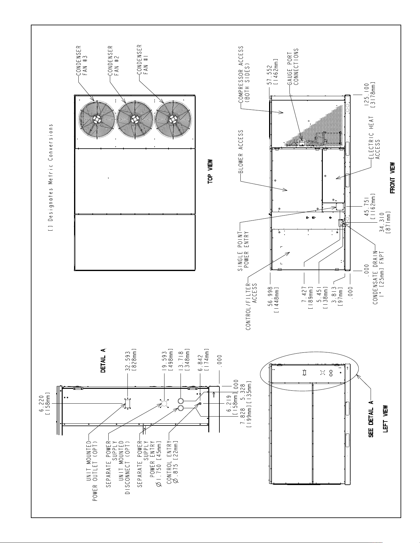
FIGURE 1
UNIT DIMENSIONS
6
ST-A1207-11
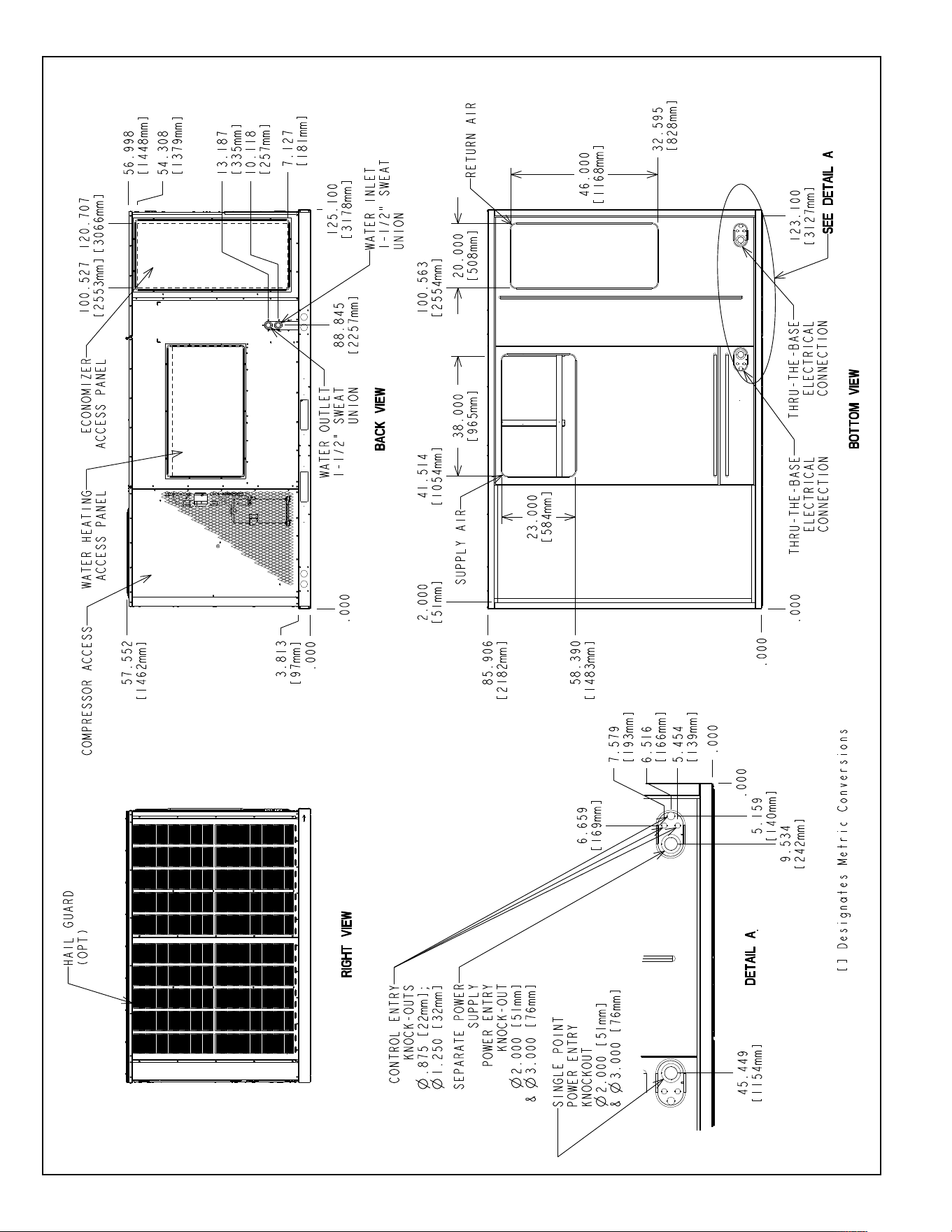
FIGURE 2
UNIT DIMENSIONS
7
GENERAL DATA - RLHL
NOTES:
1. Cooling Performance is rated at 95° F ambient, 80° F entering dry bulb, 67° F entering wet bulb. Gross capacity does not include the effect of fan motor heat. AHRI capacity is net and includes
the effect of fan motor heat. Units are suitable for operation to ±20% of nominal cfm. Units are certified in accordance with the Unitary Air Conditioner Equipment certification program, which is
based on AHRI Standard 210/240 or 360.
2. EER and/or SEER are rated at AHRI conditions and in accordance with DOE test procedures.
3. Integrated Energy Efficiency Ratio (IEER) is rated in accordance with AHRI Standard 210/240 or 340/360.
4. Not applicable to these units.
5. Outdoor Sound Rating shown is tested in accordance with ARI Standard 270. 25 Ton Model (B300) is outside the scope of AHRI Standard 340/360.
Model RLRL- Series C180CL C180CM C180DL C180DM
Model RLRL- Series (with VFD) H180CR H180CS H180DR H180DS
Cooling Performance
1
Gross Cooling Capacity Btu [kW] 178,000 [52.15] 178,000 [52.15] 178,000 [52.15] 178,000 [52.15]
EER, SEER
2
12.2/NA 12.2/NA 12.2/NA 12.2/NA
Nominal CFM/AHRI Rated CFM [L/s] 6000/5500 [2831/2595] 6000/5500 [2831/2595] 6000/5500 [2831/2595] 6000/5500 [2831/2595]
AHRI Net Cooling Capacity Btu [kW] 174,000 [50.98] 174,000 [50.98] 174,000 [50.98] 174,000 [50.98]
Net Sensible Capacity Btu [kW] 128,000 [37.5] 128,000 [37.5] 128,000 [37.5] 128,000 [37.5]
Net Latent Capacity Btu [kW] 46,000 [13.48] 46,000 [13.48] 46,000 [13.48] 46,000 [13.48]
IEER
3
13.2/15 13.2/15 13.2/15 13.2/15
Net System Power kW 14.15 14.15 14.15 14.15
Compressor
No./Type 2/Scroll 2/Scroll 2/Scroll 2/Scroll
Outdoor Sound Rating (dB)
5
91 91 91 91
Outdoor Coil - Fin Type Louvered Louvered Louvered Louvered
Tube Type MicroChannel MicroChannel MicroChannel MicroChannel
Tube Size in. [mm] OD 1 [25.4] 1 [25.4] 1 [25.4] 1 [25.4]
Face Area sq. ft. [sq. m] 50.8 [4.72] 50.8 [4.72] 50.8 [4.72] 50.8 [4.72]
Rows / FPI [FPcm] 1 / 23 [9] 1 / 23 [9] 1 / 23 [9] 1 / 23 [9]
Indoor Coil - Fin Type Louvered Louvered Louvered Louvered
Tube Type Rifled Rifled Rifled Rifled
Tube Size in. [mm] 0.375 [9.5] 0.375 [9.5] 0.375 [9.5] 0.375 [9.5]
Face Area sq. ft. [sq. m] 26.67 [2.48] 26.67 [2.48] 26.67 [2.48] 26.67 [2.48]
Rows / FPI [FPcm] 2 / 18 [7] 2 / 18 [7] 2 / 18 [7] 2 / 18 [7]
Refrigerant Control TX Valves TX Valves TX Valves TX Valves
Drain Connection No./Size in. [mm] 1/1 [25.4] 1/1 [25.4] 1/1 [25.4] 1/1 [25.4]
Outdoor Fan - Type Propeller Propeller Propeller Propeller
No. Used/Diameter in. [mm] 3/24 [609.6] 3/24 [609.6] 3/24 [609.6] 3/24 [609.6]
Drive Type/No. Speeds Direct/1 Direct/1 Direct/1 Direct/1
CFM [L/s] 10000 [4719] 10000 [4719] 10000 [4719] 10000 [4719]
No. Motors/HP 3 at 1/3 HP 3 at 1/3 HP 3 at 1/3 HP 3 at 1/3 HP
Motor RPM 1075 1075 1075 1075
Indoor Fan - Type FC Centrifugal FC Centrifugal FC Centrifugal FC Centrifugal
No. Used/Diameter in. [mm] 2/18x9 [457x229] 2/18x9 [457x229] 2/18x9 [457x229] 2/18x9 [457x229]
Drive Type Belt (Adjustable) Belt (Adjustable) Belt (Adjustable) Belt (Adjustable)
No. Speeds Single / Multiple Single / Multiple Single / Multiple Single / Multiple
No. Motors 1111
Motor HP 3535
Motor RPM 1725 1725 1725 1725
Motor Frame Size 56 184 56 184
Filter - Type Disposable Disposable Disposable Disposable
Furnished Yes Yes Yes Yes
(NO.) Size Recommended in. [mm x mm x mm] (8)2x25x20 [51x635x508] (8)2x25x20 [51x635x508] (8)2x25x20 [51x635x508] (8)2x25x20 [51x635x508]
Refrigerant Charge Oz. (Sys. 1/Sys. 2) [g] 170/173 [4820/4905] 170/173 [4820/4905] 170/173 [4820/4905] 170/173 [4820/4905]
Weights
Net Weight lbs. [kg] 1883 [854] 1921 [871] 1883 [854] 1921 [871]
Ship Weight lbs. [kg] 2009 [911] 2047 [929] 2009 [911] 2047 [929]
Continued ->
% % %
Model RLHL- Series D180CL D180CM D180DL D180DM
Cooling Performance
1
Gross Cooling Capacity Btu [kW] 182,000 [53.33] 182,000 [53.33] 182,000 [53.33] 182,000 [53.33]
EER/SEER
2
12.4/NA 12.4/NA 12.4/NA 12.4/NA
Nominal CFM/AHRI Rated CFM [L/s] 6000/5800 [2831/2737] 6000/5800 [2831/2737] 6000/5800 [2831/2737] 6000/5800 [2831/2737]
AHRI Net Cooling Capacity Btu [kW] 176,000 [51.57] 176,000 [51.57] 176,000 [51.57] 176,000 [51.57]
Net Sensible Capacity Btu [kW] 130,400 [38.21] 130,400 [38.21] 130,400 [38.21] 130,400 [38.21]
Net Latent Capacity Btu [kW] 45,600 [13.36] 45,600 [13.36] 45,600 [13.36] 45,600 [13.36]
IEER
3
13 13 13 13
Net System Power kW 14.23 14.23 14.23 14.23
Compressor
No./Type 2/Scroll 2/Scroll 2/Scroll 2/Scroll
Outdoor Sound Rating (dB)
5
91919191
Outdoor Coil - Fin Type Louvered Louvered Louvered Louvered
Tube Type MicroChannel MicroChannel MicroChannel MicroChannel
MicroChannel Depth in. [mm] 1 [25.4] 1 [25.4] 1 [25.4] 1 [25.4]
Face Area sq. ft. [sq. m] 50.8 [4.72] 50.8 [4.72] 50.8 [4.72] 50.8 [4.72]
Rows / FPI [FPcm] 1 / 23 [9] 1 / 23 [9] 1 / 23 [9] 1 / 23 [9]
Indoor Coil - Fin Type Louvered Louvered Louvered Louvered
Tube Type Rifled Rifled Rifled Rifled
Tube Size in. [mm] OD 0.375 [9.5] 0.375 [9.5] 0.375 [9.5] 0.375 [9.5]
Face Area sq. ft. [sq. m] 26.67 [2.48] 26.67 [2.48] 26.67 [2.48] 26.67 [2.48]
Rows / FPI [FPcm] 2 / 18 [7] 2 / 18 [7] 2 / 18 [7] 2 / 18 [7]
Refrigerant Control TX Valves TX Valves TX Valves TX Valves
Drain Connection No./Size in. [mm] 1/1 [25.4] 1/1 [25.4] 1/1 [25.4] 1/1 [25.4]
Outdoor Fan - Type Propeller Propeller Propeller Propeller
No. Used/Diameter in. [mm] 3/24 [609.6] 3/24 [609.6] 3/24 [609.6] 3/24 [609.6]
Drive Type/No. Speeds Direct/1 Direct/1 Direct/1 Direct/1
CFM [L/s] 10000 [4719] 10000 [4719] 10000 [4719] 10000 [4719]
No. Motors/HP 3 at 1/3 HP 3 at 1/3 HP 3 at 1/3 HP 3 at 1/3 HP
Motor RPM 1075 1075 1075 1075
Indoor Fan - Type FC Centrifugal FC Centrifugal FC Centrifugal FC Centrifugal
No. Used/Diameter in. [mm] 2/18x9 [457x229] 2/18x9 [457x229] 2/18x9 [457x229] 2/18x9 [457x229]
Drive Type Belt (Adjustable) Belt (Adjustable) Belt (Adjustable) Belt (Adjustable)
No. Speeds Single Single Single Single
No. Motors 1 1 1 1
Motor HP 3 5 3 5
Motor RPM 1725 1725 1725 1725
Motor Frame Size 56 184 56 184
Potable Water Heat Recovery
Heat Exchanger Type Vented Double-Wall Flat Plate Vented Double-Wall Flat Plate Vented Double-Wall Flat Plate Vented Double-Wall Flat Plate
Material Cu Brazed Stainless Steel Cu Brazed Stainless Steel Cu Brazed Stainless Steel Cu Brazed Stainless Steel
No. Flat Plates 50 50 50 50
Unit Water Connections No./Size in. [mm] 2/1.625 [41.3] 2/1.625 [41.3] 2/1.625 [41.3] 2/1.625 [41.3]
Water Pump - Type Centrifugal Centrifugal Centrifugal Centrifugal
Drive Type/No. Speeds Direct/1 Direct/1 Direct/1 Direct/1
Housing Material Stainless Steel Stainless Steel Stainless Steel Stainless Steel
GPM [L/s] 30 [1.89] 30 [1.89] 30 [1.89] 30 [1.89]
Head Pressure ft. H2O [kPa] 25 [74.7] 25 [74.7] 25 [74.7] 25 [74.7]
Motor HP 1/3 1/3 1/3 1/3
Motor RPM 3450 3450 3450 3450
Filter - Type Disposable Disposable Disposable Disposable
Furnished Yes Yes Yes Yes
(NO.) Size Recommended in. [mm x mm x mm] (8)2x25x20 [51x635x508] (8)2x25x20 [51x635x508] (8)2x25x20 [51x635x508] (8)2x25x20 [51x635x508]
Refrigerant Charge Oz. (Sys. 1/Sys. 2) [g] 171/201 [4848/5698] 171/201 [4848/5698] 171/201 [4848/5698] 171/201 [4848/5698]
Weights
Net Weight lbs. [kg] 1895 [860] 1924 [873] 1895 [860] 1924 [873]
Ship Weight lbs. [kg] 2022 [917] 2051 [930] 2022 [917] 2051 [930]
8
ELECTRICAL DATA - RLHL
% % %
D180CL D180CM D180DL D180DM
Unit Operating Voltage Range 187-253 187-253 414-506 414-506
Volts 208/230 208/230 460 460
Minimum Circuit Ampacity 77/77 81/81 40 42
Minimum Overcurrent Protection Device
Size
90/90 90/90 45 45
Maximum Overcurrent Protection Device
Size
100/100 100/100 50 50
No. 2 2 2 2
Volts 200/230 200/230 460 460
Phase 3 3 3 3
RPM 3450 3450 3450 3450
HP, Compressor 1 7 1/2 7 1/2 7 1/2 7 1/2
Amps (RLA), Comp. 1 25/25 25/25 12.8 12.8
Amps (LRA), Comp. 1 164/164 164/164 100 100
HP, Compressor 2 7 1/2 7 1/2 7 1/2 7 1/2
Amps (RLA), Comp. 2 25/25 25/25 12.8 12.8
Amps (LRA), Comp. 2 164/164 164/164 100 100
No. 3 3 3 3
Volts 208/230 208/230 460 460
Phase 1 1 1 1
HP 1/3 1/3 1/3 1/3
Amps (FLA, each) 2.4/2.4 2.4/2.4 1.4 1.4
Amps (LRA, each) 4.7/4.7 4.7/4.7 2.4 2.4
No. 1 1 1 1
Volts 208/230 208/230 460 460
Phase 3 3 3 3
HP 3 5 3 5
Amps (FLA, each) 11.5/11.5 14.9/14.9 4.6 6.6
Amps (LRA, each) 74.5/74.5 95/95 38.1 47.5
No. 1 1 1 1
Volts 208/230 208/230 208/230 208/230
Phase 1 1 1 1
HP 1/3 1/3 1/3 1/3
Amps (FLA, each) 1.7 1.7 1.7 1.7
Amps (LRA, each) 5.1 5.1 5.1 5.1
Evaporator Fan
Water Pump
ELECTRICAL DATA - RLHL- SERIES
Unit Information
Compressor Motor
Condenser Motor
9
!"#$$%&'()"%*)'(+,!%-'.'-+(/%0%1234
5644 78893: ;344 76585: <344 766=;: 5644 78893: ;344 76585: <344 766=;: 5644 78893: ;344 76585: <344 766=;:
5; (>?@A%B(C*%7D&: !"#$% &"'$#( !"'$) &"!$)( !"%$* &"!$!( !"%$) &"!$*( !*'$* &*+$+( !*!$) &*+$,( !"!$" &"!$"( !*"$- &*)$"( !')$* &*,$)(
768E9: .>FGH%D&
34 (>?@A%B(C*%7D&: !"'$+ &"!$)( !"%$+ &"!$*( !*+$, &"%$-( !*)$% &"%$,( !*%$) &*+$"( !*%$" &*+$'( !*)$# &"%$)( !**$' &*)$%( !'+$' &*,$-(
76=E5: .>FGH%D&
3; (>?@A%B(C*%7D&: !"%$, &"!$'( !*+$, &"%$-( !*,$! &"%$'( !*,$' &"%$'( !')$" &*,$)( !'+$) &*,$+( !*,$# &"%$*( !*!$+ &*+$-( !',$% &*,$'(
769E<: .>FGH%D&
94 (>?@A%B(C*%7D&: !*+$# &"%$-( !*-$- &"%$%( !*#$# &*)$,( !*#$* &*)$,( !'+$% &*,$#( !',$" &*,$*( !*#$- &*)$,( !*%$* &*+$'( !'#$) &*-$)(
786E6: .>FGH%D&
9; (>?@A%B(C*%7D&: !*-$" &"%$%( !*"$" &*)$"( !**$) &*)$'( !**$" &*)$!( !'-$# &*,$!( !'-$% &*-$)( !**$, &*)$'( !'+$) &*,$+( !'"$, &*-$#(
78;E4: .>FGH%D&
244 (>?@A%B(C*%7D&: !*"$* &*)$"( !*'$* &*+$+( !*'$" &*+$+( !*!$# &*+$#( !'#$! &*-$,( !'"$# &*-$#( !*!$, &*+$-( !',$# &*,$"( !'*$- &*-$'(
785E3: .>FGH%D&
24; (>?@A%B(C*%7D&: !*'$! &*+$,( !*%$' &*+$'( !*%$+ &*+$*( !')$, &*+$%( !'*$- &*-$'( !'*$% &*-$%( !')$+ &*+$%( !'-$! &*,$%( !''$" &*#$)(
7<4E=: .>FGH%D&
224 (>?@A%B(C*%7D&: !*%$% &*+$!( !'+$! &*,$#( !')$' &*,$)( !',$+ &*,$#( !''$' &*#$+( !'!$- &*#$-( !',$) &*,$#( !'"$, &*-$#( !'!$* &*#$#(
7<8E8: .>FGH%D&
22; (>?@A%B(C*%7D&: !',$) &*,$#( !'-$% &*-$)( !',$- &*,$"( !'#$) &*-$)( !'%$, &*#$"( !'%$! &*#$'( !'#$) &*-$)( !'*$* &*-$!( !'%$! &*#$'(
7<=E2: .>FGH%D&
264 (>?@A%B(C*%7D&: !'#$, &*-$+( !'*$+ &*-$*( !'-$% &*-$)( !'"$! &*-$"( !!)$* &*#$%( !!+$- &*"$+( !'"$% &*-$*( !'!$) &*#$,( !!)$% &*"$)(
7<3E9: .>FGH%D&
26; (>?@A%B(C*%7D&: !'*$- &*-$'( !'!$, &*#$,( !'"$" &*-$#( !''$' &*#$+( !!,$+ &*"$#( !!,$' &*"$*( !''$! &*#$+( !'%$# &*#$*( !!,$+ &*"$#(
7;2E5: .>FGH%D&
),()"+,!%+,1##"%'+"%I%34JK%76=E5J-:%LM)
,$*
,$*
,$,
,$*
FM)
-KN%7OP:
,$*
,$*
,$'
,$*
,$#
=5JK%729E<J-:
=8JK%725E6J-:
52JK%762E5J-:
-$+
-$+
-$+
-$+
,$!
-$+
-$+
,$'
-$+
"$'
"$#
"$'
"$"
"$"
"$#
"$"
#$,
"$"
"$"
"$'
"$'
"$"
"$'
#$)
"$*
"$,
"$"
"$-
"$-
"$,
"$-
#$#
"$-
"$-
"$)
"$-
"$+
"$+
"$)
"$+
#$#
"$+
"$+
#$'
"$+
#$,
#$,
-$%
#$,
#$!
#$"
#$!
#$"
#$*
#$"
#$"
#$,
#$"
#$"
#$!
#$!
#$'
#$!
#$#
#$!
#$,
#$"
#C(O)(%&'()"%()N.)"'(C")%JK%7J-:
-$"
-$+
-$"
-$"
-$"
-$"
-$"
-$-
-$"
-$%
-$%
-$%
-$%
-$*
-$%
-$%
-$"
-$%
#$,
#$,
#$,
#$,
-$%
10
VI. INSTALLATION
A. GENERAL
1. PRE-INSTALLATION CHECK-POINTS
Before attempting any installation, the following points should be carefully consid-
ered:
a. Structural strength of supporting members.
(rooftop installation)
b. Clearances and provision for servicing.
c. Power supply and wiring.
d. Air duct connections.
e. Drain facilities and connections.
f. Location for minimum noise.
g. Water piping supply length and routing
2. LOCATION
These units are designed for outdoor installations. They are not to be installed with-
in any part of a structure such as an attic, crawl space, closet, or any other place
where condenser air flow is restricted or other than outdoor ambient conditions pre-
vail. Since the application of the units is of the outdoor type, it is important to consult
your local code authorities at the time the first installation is made.
B. H2AC ROOFTOP UNIT SPECIAL CONSIDERATIONS
Since the waste-heat recovery/water heating feature of the H2AC rooftop unit only func-
tions during the cooling mode, the unit should be installed to serve the area of the struc-
ture having the largest cooling run-time, for instance the kitchen area of a restaurant, in
order to provide the greatest water heating and energy saving benefits.
The H
2AC rooftop unit is equipped with an outdoor temperature sensor that energizes the
water pump continuously below 35°F to minimize the chance of the water system freez-
ing, however this is not intended to be the sole method of unit freeze protection. If the
H
2AC rooftop unit is installed in a geographic location where freezing temperature
can occur, the water lines, valves, and couplings connected outside the unit must
be adequately protected with insulation and heat tape suitable for the lowest
expected temperatures.
Alternately, the unit and all connecting lines can be drained of water and the unit
heat exchanger, pump, and internal piping winterized using a non-toxic recreational
vehicle type of anti-freeze suitable for potable water systems.
E
D
C
B
A
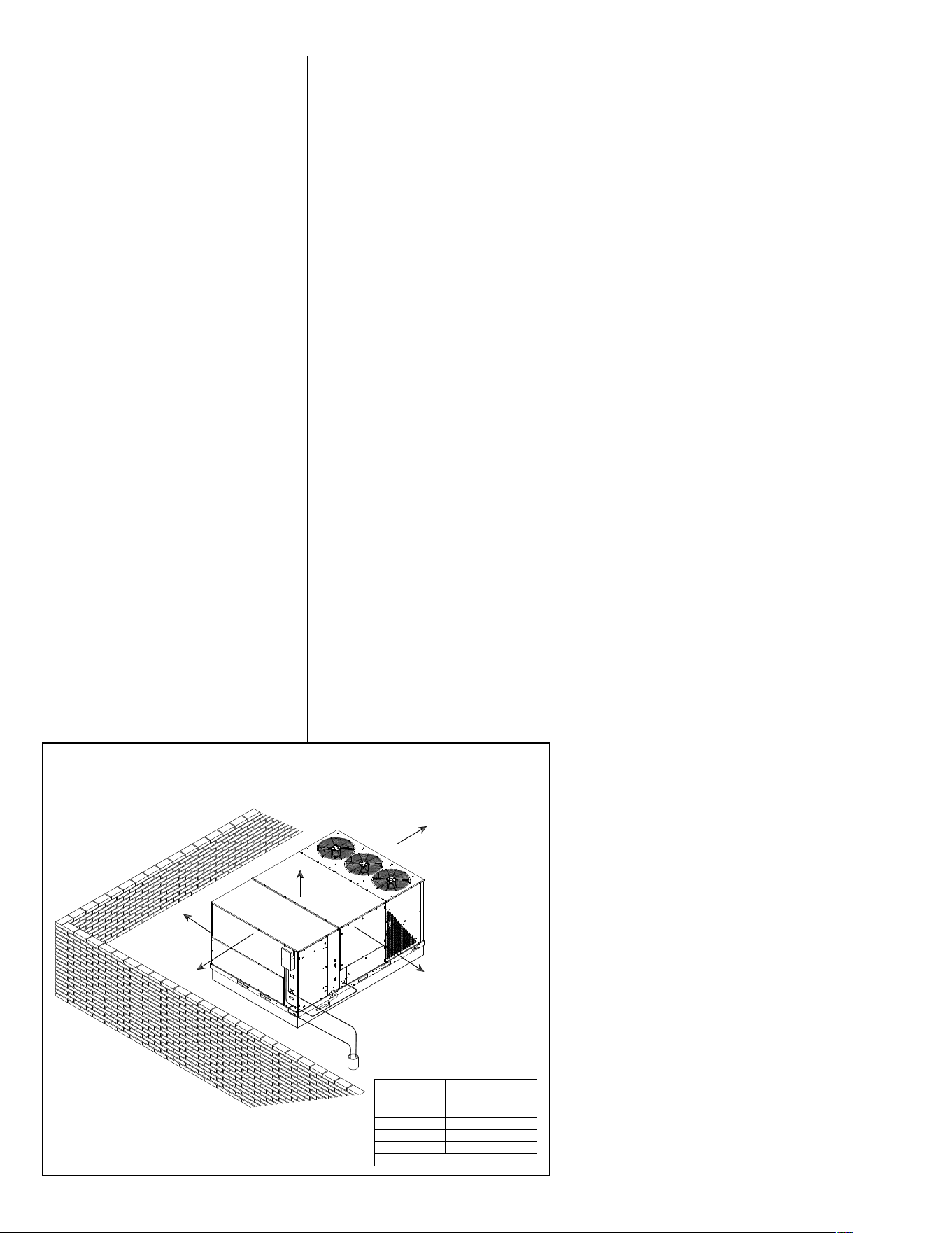
Recommended
Clearance in. [mm]
Location
80 [2032]
18 [457]
18 [457]
18 [457]*
60 [1524]
* Without Economizer 48 [1219] With Economizer
A - Front
B - Condenser Coil
C - Duct Side
D - Evaporator End
E - Above
FIGURE 3
PACKAGED AIR CONDITIONER
FLAT ROOFTOP INSTALLATION, ATTIC OR DROP CEILING DISTRIBUTING SYSTEM.
MOUNTED ON ROOFCURB. CURB MUST BE LEVEL.
ST-A1207-13-00
11
The H2AC rooftop unit is equipped with a water leak sensor
designed to sense water that would accumulate in the pan under
the water pump and refrigerant-to-water heat exchanger assem-
bly located on the blower deck. If a leak is sensed in that area an
alarm is triggered on the RTU-C (ClearControl) control board and
a water shutoff relay is energized to activate the optional RXMV-
AH electric water shut-off valve. It is strongly recommended that
the RXMV-AH be installed to minimize the chance of water dam-
age to the structure in case of a water leak in the unit.
C. CLEARANCES
The following minimum clearances must be observed for prop-
er unit performance and serviceability.
1. Provide 80" minimum clearance at the front of the unit to
facilitate removal of the drain pan and return air filters.
Provide 18" minimum clearance at all other sides of the unit.
2. Provide 60" minimum clearance between top of unit and
maximum 3 foot overhang.
3. Unit is design certified for application on combustible floor-
ing with 0" minimum clearance.
4. See Figure 3 for illustration of minimum installation-service
clearances.
D. ROOFTOP INSTALLATION
1. Before locating the unit on the roof, make sure that the
strength of the roof and beams is adequate at that point to
support the weight involved. This is very important and
user’s responsibility.
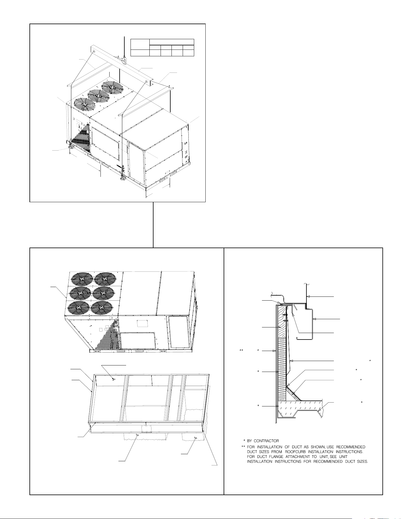
2. For rigging and roofcurb details, see Figures 4 and 5. Use
field-furnished spreaders.
CAPACITY TONS
(KW)
CORNER WEIGHTS BY PERCENTAGE
A
B
C
D
A
B
C
D
LIFTING BEAM
CABLE OR CHAIN
SPREADER BAR
5/8” [14.9 MM]
SHACKLE
EACH CORNER
47-3/4”
[1213MM]
C
G
C
G
CENTER
OF
GRAVITY
15 [52.8]
26% 29%
18%
27%
56-5/8”
[1438MM]
FIGURE 4
PACKAGED AIR CONDITIONER
RIGGING FOR LIFTING
ST-A1207-25
PACKAGED AIR CONDITIONER
ROOFCURB INSTALLATION
UNIT BASE FRAME
ROOFTOP UNIT
ROOFCURB
ROOF FLASHING
ROOFING
CANT STRIP
ROOF DECK
INSULATION
INSULATION
DUCT
NAILER STRIP
GASKET
ST-A0888-02
FIGURE 5
UNIT
ST-A1125-14
ROOFCURB
INSTALL GASKET
DUCT FLANGE NOT
TO EXCEED
1” [25 mm]
RETURN DUCT
50-3/4” X 22” [1289 x 559 mm] MAX
SUPPLY DUCT
42” X 23-3/4” [1089 X 603 mm] MAX
CAULK ALL JOINTS
WATERTIGHT
NAILING STRIP

3. For roofcurb assembly, see Roofcurb Installation Instructions.
4. If the roofcurb is not used, provisions for disposing of condensate water runoff must
be provided.
5. The unit should be placed on a solid and level roofcurb or platform of adequate
strength. See Figure 6.
6. The location of the unit on the roof should be such as to provide proper access for
inspection and servicing.
IMPORTANT: If unit will not be put into service immediately, cover supply and return
openings to prevent excessive condensation.
VII. DUCTWORK
Ductwork should be fabricated by the installing contractor in accordance with local codes and
NFPA90A. Industry manuals may be used as a guide when sizing and designing the duct sys-
tem - contact Air Conditioning Contractors of America, 2800 Shirlington Road, Suite 300,
Arlington, VA 22206, http:/www.acca.org.
The unit should be placed as close to the space to be air conditioned as possible allowing
clearance dimensions as indicated. Ducts should be run as directly as possible to supply and
return outlets. Use of non-flammable waterproof flexible connectors on both supply and return
connections at the unit to reduce noise transmission is recommended.
It is preferable to install the unit on the roof of the structure if the registers or diffusers are
located on the wall or in the ceiling. A slab installation could be considered when the registers
are low on a wall or in the floor.
On ductwork exposed to outside air conditions of temperature and humidity, use a minimum
of 2" of insulation and a vapor barrier. Distribution system in attic, furred space or crawl space
should be insulated with at least 2" of insulation with vapor barrier. One-half to 1" thickness of
insulation is usually sufficient for ductwork inside the air conditioned space.
Balancing dampers should be provided for each branch duct in the supply system.
Ductwork should be properly supported from the structure.
When installing ductwork, consider the following items:
1. Noncombustible flexible connectors should be used between ductwork and unit to
reduce noise and vibration transmission into the ductwork.
2. When auxiliary heaters are installed, use noncombustible flexible connectors and clear-
ance to combustible material of 0" for the first 3 feet of discharge duct. Clearance to unit
top and side is 0".
VIII. FILTERS
This unit is provided with 8 - 20" x 25" x 2" disposable filters. When replacing filters, ensure
they are inserted fully to the back to prevent bypass. See Figure 1.
Recommended supplier of this filter is Glassfloss Industries, Inc. or
AAF International
215 Central Avenue
P.O. Box 35690
Louisville, KY 40232
Phone: 1-800-501-3146
Part #: 54-42541-04 (20” x 25” x 2”)
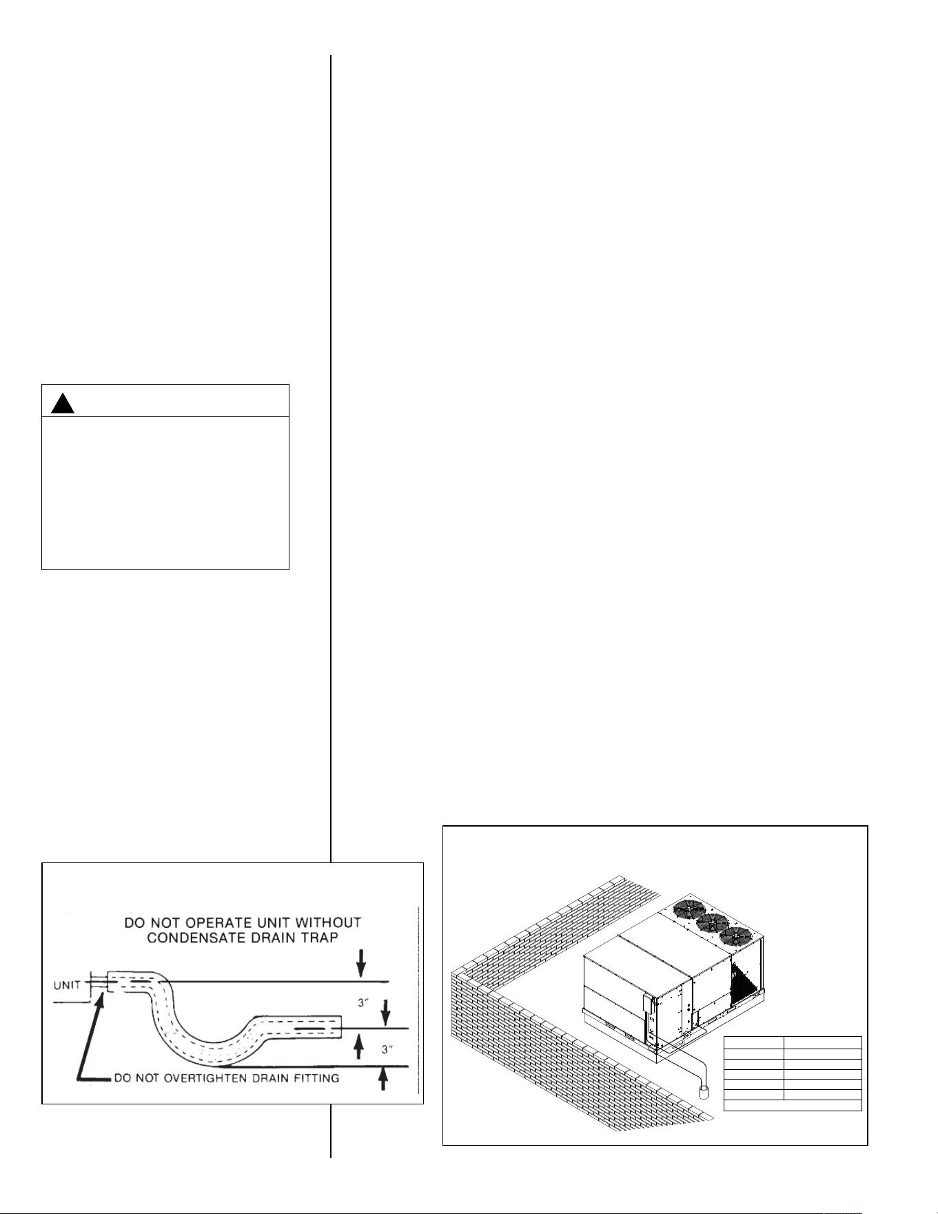
IX. CONDENSATE DRAIN
IMPORTANT: Install a condensate trap to ensure proper condensate drainage. See
Figure 7.
The condensate drain pan has a threaded female 1 inch NPT (11.5 TPI) connection.
Consult local codes or ordinances for specific requirements of condensate drain piping
and disposal.
• To use the removable drain pan feature of this unit, some of the condensate line joints
should assembled for easy removal and cleaning.
• Use a thin layer of Teflon tape or paste on drain pan connections and install only hand
tight.
• Do not over tighten drain pan connections as damage to the drain pan may occur.
• Drain line MUST NOT block service access panels.
12
13
• Drain line must be no smaller than drain pan outlet and adequately sized to accommo-
date the condensate discharge from the unit.
• Drain line should slope away from unit a minimum of 1/8” per foot to ensure proper
drainage.
• Drain line must be routed to an acceptable drain or outdoors in accordance with local
codes.
• Do not connect condensate drain line to a closed sewer pipe.
• Drain line may need insulation or freeze protection in certain applications.
X. ELECTRICAL WIRING
Field wiring must comply with the National Electrical Code* and local ordinances that may
apply.
*C.E.C. in Canada
A. POWER WIRING
1. This unit incorporates single-point electrical connections for the unit and electric heat
accessory.
2. It is important that proper electrical power is available to the unit. Voltage should not
vary more than 10% from the values marked on the unit rating plate. Phase voltages
must be balanced within 3%.
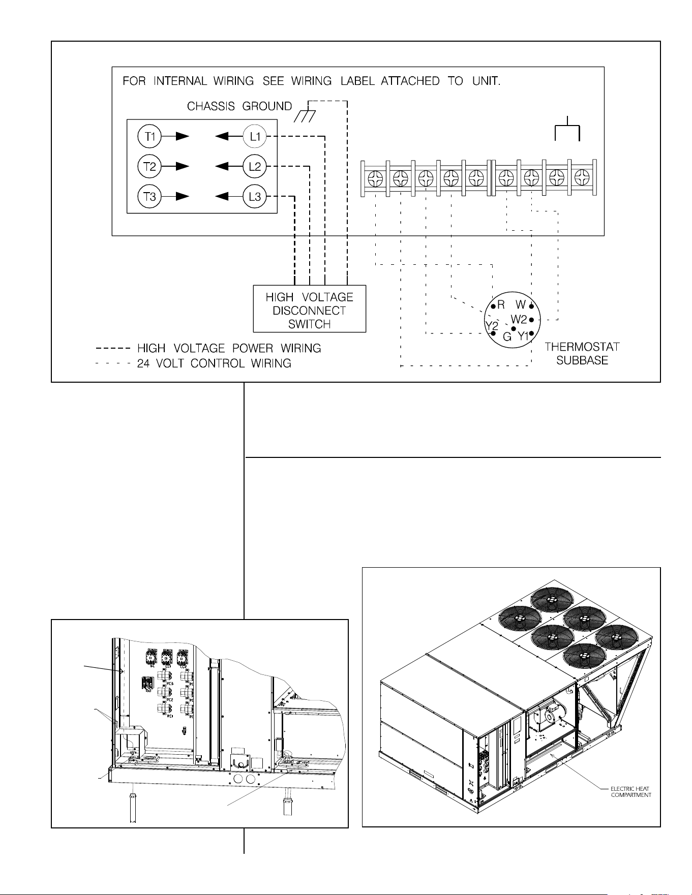
3. Install a branch circuit disconnect within sight of the unit. See Figure 8. Use the unit
rating plate or Tables A, B, C, and D to determine the required size.
4. The branch circuit wire must be sized in accordance with the National Electrical Code
(C.E.C. in Canada) and local ordinances that may apply using the minimum circuit
ampacity found on the unit rating plate.
5. Field-installed power wiring must be run through grounded rain-tight conduit attached
to the unit power entry panel and connected as follows:
UNITS WITHOUT ELECTRIC HEAT - Connect power wiring to the power terminal
block located on the left side of the electric heat compartment. Connect the ground wire
to the adjacent ground lug.
UNITS WITH FACTORY INSTALLED ELECTRIC HEAT - Connect power wiring to the
power terminal block located on the electric heater kit. Connect the ground wire to the
adjacent ground lug. DO NOT connect aluminum wiring directly to the electric heater
terminal block. Wiring to the unit contactors is factory-connected.
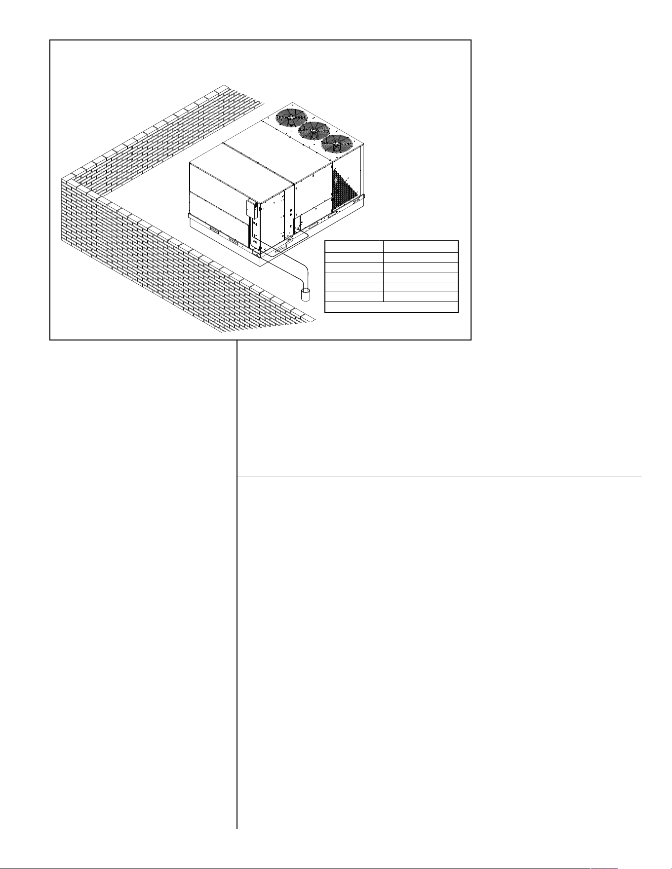
Recommended
Clearance in. [mm]
Location
80 [2032]
18 [457]
18 [457]
18 [457]*
60 [1524]
* Without Economizer 48 [1219] With Economizer
A - Front
B - Condenser Coil
C - Duct Side
D - Evaporator End
E - Above
FIGURE 6
PACKAGED AIR CONDITIONER
FLAT ROOFTOP INSTALLATION, ATTIC OR DROP CEILING DISTRIBUTION
SYSTEM. MOUNTED ON ROOFCURB. CURB MUST BE LEVEL.
ST-A1207-13
14
THE UNIT MUST BE PERMANENT-
LY GROUNDED. A GROUNDING
LUG IS PROVIDED IN THE ELEC-
TRIC HEAT ACCESS AREA FOR A
GROUND WIRE. FAILURE TO
GROUND THIS UNIT CAN RESULT
IN FIRE OR ELECTRICAL SHOCK
CAUSING PROPERTY DAMAGE,
SEVERE PERSONAL INJURY OR
DEATH.
▲WARNING
!
6. For field installation of an electric heater kit, follow the instructions below. Refer to
the information supplied with the kit.
a. Removing screws as required, open heater access door and detach adjacent
power entry panel.
b. Remove unit contactor wires (1L1, 1L2, 1L3) from unit terminal block on the left
side of the electric heat compartment. Remove and discard the terminal block
and the adjacent ground lug.
c. Remove the heater kit block-off panel and install the heater kit in its place using
the screws previously removed.
d. Connect the unit contactor wires (1L1, 1L2, 1L3) to the compressor fuse block
on the heater kit.
e. Re-install the power entry panel & run conduit and the proper size field wiring
through the opening in the panel.
f. Connect field wiring to the power terminal block located on the electric heater
kit. Connect ground wire to the adjacent ground lug.
g. Connect heater kit control plug to the receptacle on the control wiring harness.
h. Close heater access door and secure with screws previously removed.
B. CONTROL WIRING (Class II)
1. Low voltage wiring should not be run in conduit with power wiring.
2. Control wiring is routed through the 7/8" hole in the unit side panel. See Figures 1
and 10. Use a minimum #18 AWG thermostat wire. For wire lengths exceeding
50', use #16 AWG thermostat wire. Connect the control wiring to the low voltage
terminal block inside the unit control box.
3. Recommended thermostats can be found in the thermostat specifications catalog
T11-001.
4. Figure 9 shows representative low voltage connection diagrams. Read your ther-
mostat installation instructions for any special requirements for your specific ther-
mostat.
NOTE — Units installed in Canada require that an outdoor thermostat (30,000
min. cycles of endurance) be installed and be wired with C.E.C. Class I wiring.
D. INTERNAL WIRING
1. A diagram of the internal wiring of this unit is located on the inside of the electrical
access panel. If any of the original wire, as supplied with the appliance must be
replaced, the wire gauge and insulation must be the same as original wiring.
E. THERMOSTAT
The thermostat should be mounted on an inside wall about five feet above the floor
in a location where it will not be affected by unconditioned air, sun, or drafts from
open doors or other sources. READ installation instructions in heat pump thermostat
package CAREFULLY because each has some different wiring requirements.
FIGURE 7
CONDENSATE DRAIN
Recommended
Clearance in. [mm]
Location
80 [2032]
18 [457]
18 [457]
18 [457]*
60 [1524]
* Without Economizer 48 [1219] With Economizer
A - Front
B - Condenser Coil
C - Duct Side
D - Evaporator End
E - Above
FIGURE 8
BRANCH CIRCUIT DISCONNECT LOCATION
ST-A1207-13
15
XI. INDOOR AIR FLOW DATA
Belt-drive blower models have motor sheaves set for proper CFM at a typical external stat-
ic. See airflow tables for blower performance.
XII. CRANKCASE HEAT (OPTIONAL)
Crankcase heat is not required on scroll type compressors, but may be desirable under cer-
tain conditions. Wires have been provided for the addition of crankcase heaters (see wiring
diagrams).
FIGURE 17
THERMOSTAT CONNECTIONS DIAGRAMS
R Y1 Y2 G C W1 W2 W3 B
TERMINAL BLOCK
COOL
POWER
FAN
HEAT
ONLY USED
ON DUAL
FUEL OR HEAT
PUMP
MODELS
LOW VOLTAGE
THERMOSTAT CONNECTIONS
ST-A1125-12-00
FIGURE 9
ST-A1125-10B
FIGURE 10
ST-A1125-04B
FIGURE 11
RUN THERMOSTAT
WIRING IN THIS
CHASE TO
CONTROL
BOARD
(2) CAP PLUGS
BASE
CONTROL
ENTRY
BASE
POWER
ENTRY
16
AIRFLOW PERFORMANCE ! 15 TON [52.7kW] ! 60 Hz ! DOWNFLOW
0.1 [.02] 0.2 [.05] 0.3 [.07] 0.4 [.10] 0.5 [.12] 0.6 [.15] 0.7 [.17] 0.8 [.20] 0.9 [.22] 1.0 [.25] 1.1 [.27] 1.2 [.30] 1.3 [.32] 1.4 [.35] 1.5 [.37] 1.6 [.40] 1.7 [.42] 1.8 [.45] 1.9 [.47] 2.0 [.50]
RPM W RPM W RPM W RPM W RPM W RPM W RPM W RPM W RPM W RPM W RPM W RPM W RPM W RPM W RPM W RPM W RPM W RPM W RPM W RPM W
4800 [2265] — — — — — — — — — — 600 1409 629 1536 656 1671 684 1814 711 1964 738 2121 764 2286 790 2459 815 2640 840 2828 865 3023 889 3226 913 3437 — — — —
5000 [2359] — — — — — — — — 581 1358 609 1479 637 1608 664 1744 691 1888 718 2040 744 2199 770 2366 795 2541 820 2723 844 2912 869 3109 892 3314 916 3527 — — — —
5200 [2454] — — — — — — — — 590 1434 618 1557 645 1688 672 1826 699 1972 725 2125 750 2286 776 2454 800 2630 825 2814 849 3005 873 3204 896 3411 919 3625 — — — —
5400 [2548] — — — — — — 572 1402 600 1519 627 1644 654 1776 680 1916 706 2063 732 2218 757 2381 782 2551 806 2729 830 2914 854 3107 877 3307 900 3515 922 3731 — — — —
5600 [2643] — — — — — — 583 1494 610 1613 637 1739 663 1873 689 2014 714 2163 740 2320 764 2484 789 2656 812 2835 836 3022 859 3216 882 3419 904 3628 926 3846 — — — —
5800 [2737] — — — — — — 594 1594 620 1714 647 1842 672 1978 698 2121 723 2271 747 2430 772 2595 795 2769 819 2950 842 3138 864 3335 887 3538 908 3750 930 3969 — — — —
6000 [2831] — — — — 578 1588 605 1702 631 1824 657 1954 682 2091 707 2236 731 2388 756 2548 779 2715 803 2890 826 3073 848 3263 870 3461 892 3666 913 3879 — — — — — —
6200 [2926] — — — — 590 1703 616 1819 642 1942 667 2074 692 2212 716 2359 740 2513 764 2674 787 2843 810 3020 833 3204 855 3396 876 3596 897 3803 918 4017 — — — — — —
6400 [3020] — — 577 1716 602 1826 628 1944 653 2069 678 2202 702 2342 726 2490 750 2646 773 2809 796 2980 818 3158 840 3344 861 3538 883 3739 903 3947 924 4164 — — — — — —
6600 [3114] — — 589 1846 615 1958 640 2077 665 2204 689 2338 713 2480 736 2630 759 2787 782 2952 804 3124 826 3304 848 3492 869 3687 889 3890 909 4100 929 4318 — — — — — —
6800 [3209] 577 1878 603 1984 628 2098 652 2219 677 2347 700 2483 724 2627 747 2778 769 2937 791 3104 813 3278 834 3459 855 3648 876 3845 896 4050 916 4262 — — — — — — — —
7000 [3303] 591 2023 616 2131 641 2246 665 2368 689 2499 712 2636 735 2782 757 2935 779 3095 801 3263 822 3439 843 3622 864 3813 884 4012 903 4218 923 4431 — — — — — — — —
7200 [3398] 606 2177 630 2286 654 2402 678 2527 701 2659 724 2798 746 2945 768 3099 790 3262 811 3431 832 3609 852 3794 872 3986 892 4186 911 4394 930 4609 — — — — — — — —
NOTE: L-Drive left of bold line, M-Drive right of bold line.
CFM [L/s]
4800 [2265] 0.97 0.92 0.98 0.03 [.01] 0.09 [.02] — —
5000 [2359] 0.97 0.94 0.99 0.04 [.01] 0.10 [.02] — —
5200 [2454] 0.98 0.95 0.99 0.05 [.01] 0.10 [.02] — —
5400 [2548] 0.99 0.97 0.99 0.06 [.01] 0.11 [.03] — —
5600 [2643] 0.99 0.98 0.99 0.06 [.01] 0.12 [.03] 0.35 [.09] —
5800 [2737] 1.00 1.00 1.00 0.07 [.02] 0.13 [.03] 0.39 [.10] —
6000 [2831] 1.01 1.02 1.00 0.08 [.02] 0.13 [.03] 0.43 [.11] —
6200 [2926] 1.01 1.03 1.00 0.09 [.02] 0.14 [.03] 0.46 [.11] —
6400 [3020] 1.02 1.05 1.01 0.10 [.02] 0.15 [.04] 0.50 [.12] —
6600 [3114] 1.02 1.06 1.01 0.10 [.02] 0.16 [.04] 0.54 [.13] —
6800 [3209] 1.03 1.08 1.01 0.11 [.03] 0.16 [.04] — —
7000 [3303] 1.04 1.10 1.01 0.12 [.03] 0.17 [.04] — —
7200 [3398] 1.04 1.11 1.02 0.13 [.03] 0.18 [.04] — 0.38 [.09]
* Multiply correction factor times gross performance data ! resulting sensible capacity cannot exceed total capacity.
866
4
1. Factory sheave settings are shown in bold type.
2. Do not set motor sheave below minimum or maximum turns open shown.
4
5
6
0
|
|
0
1
925
2
896
M
5 [3728.5]
BK105H
1VP-56
Turns Open
1
2
3
3
Drive Package
Motor Sheave
Motor H.P. [W]
L
3 [2237.1]
BK105H
1VP-44
Model RLHL-D180 Voltage 208/230, 460 ! 3 phase 60 Hz
Air Flow
External Static Pressure ! Inches of Water [kPa]
CFM [L/s]
838
5
Blower Sheave
4. Add component resistance (below) to duct resistance to determine total External Static Pressure.
6
774
805
701
670
642
608
575
RPM
732
3. Re-adjustment of sheave required to achieve rated airflow at AHRI minimum External Static Pressure
NOTES:
AIRFLOW CORRECTION
FACTORS *
COMPONENT AIRFLOW RESISTANCE
Airflow
Wet Coil
Downflow
Economizer RA
Damper Open
Concentric Grill RXRN-
AD80 or RXRN-AD81 &
Transition RXMC-
CJ07
Concentric Grill RXRN-
AD86 & Transition
RXMC-CK08
Total MBH
Sensible MBH
Power kW
Resistance ! Inches of Water [kPa]
[ ] Designates Metric Conversions

17
XIII. WATER CONNECTIONS AND START UP FOR
XIII. POTABLE WATER HEATING
A. WATER PIPING
1. Use of copper pipe suitable for potable water is recommended. Plumbing must meet
applicable national and local plumbing and building codes.
2. The H
2AC Rooftop unit should be installed as close to the storage tank as possible to
minimize heat loss from interconnecting piping.
3. Use only solder, brazing, and pipe thread sealing materials approved for potable
water systems.
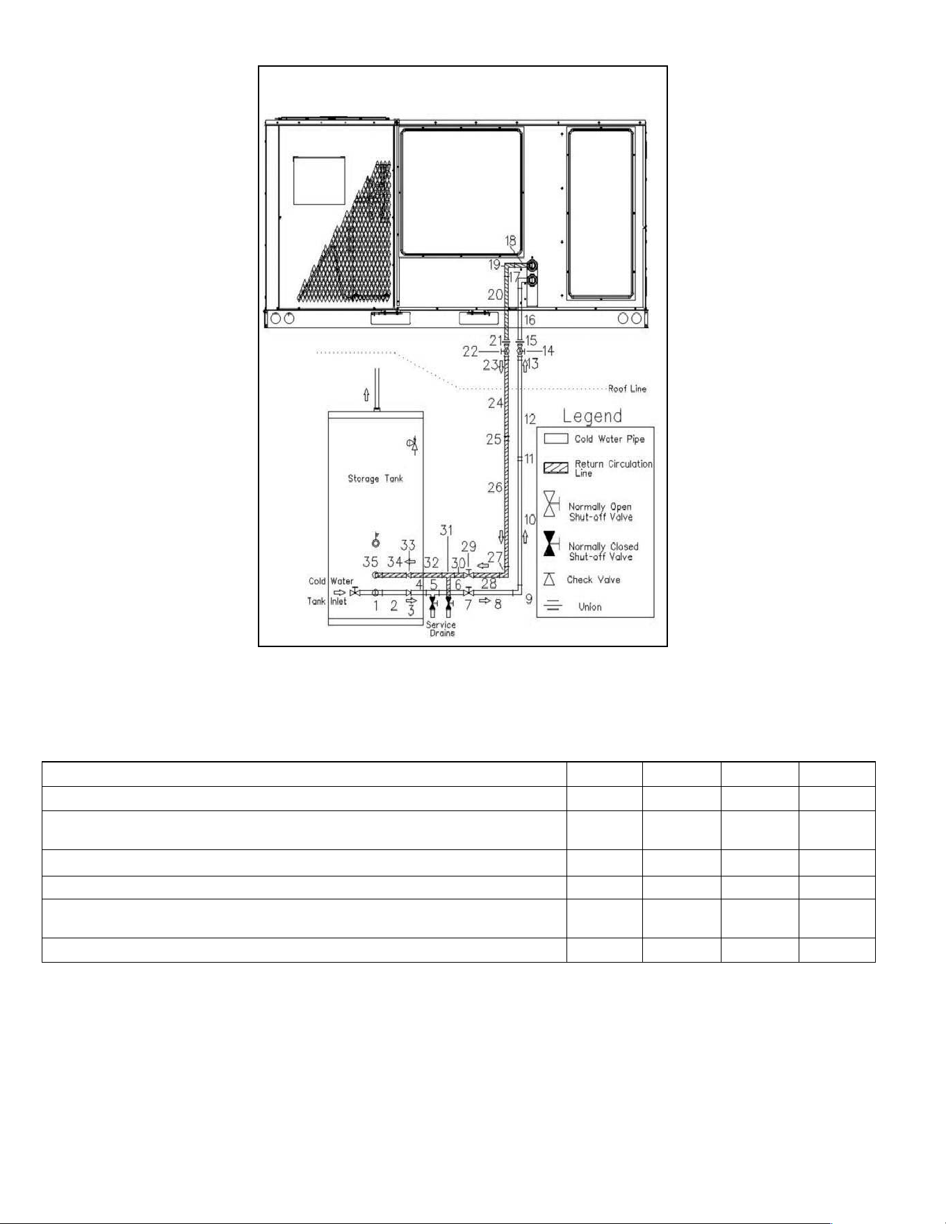
4. Refer to connection diagram for typical piping, storage tank, and valve configurations.
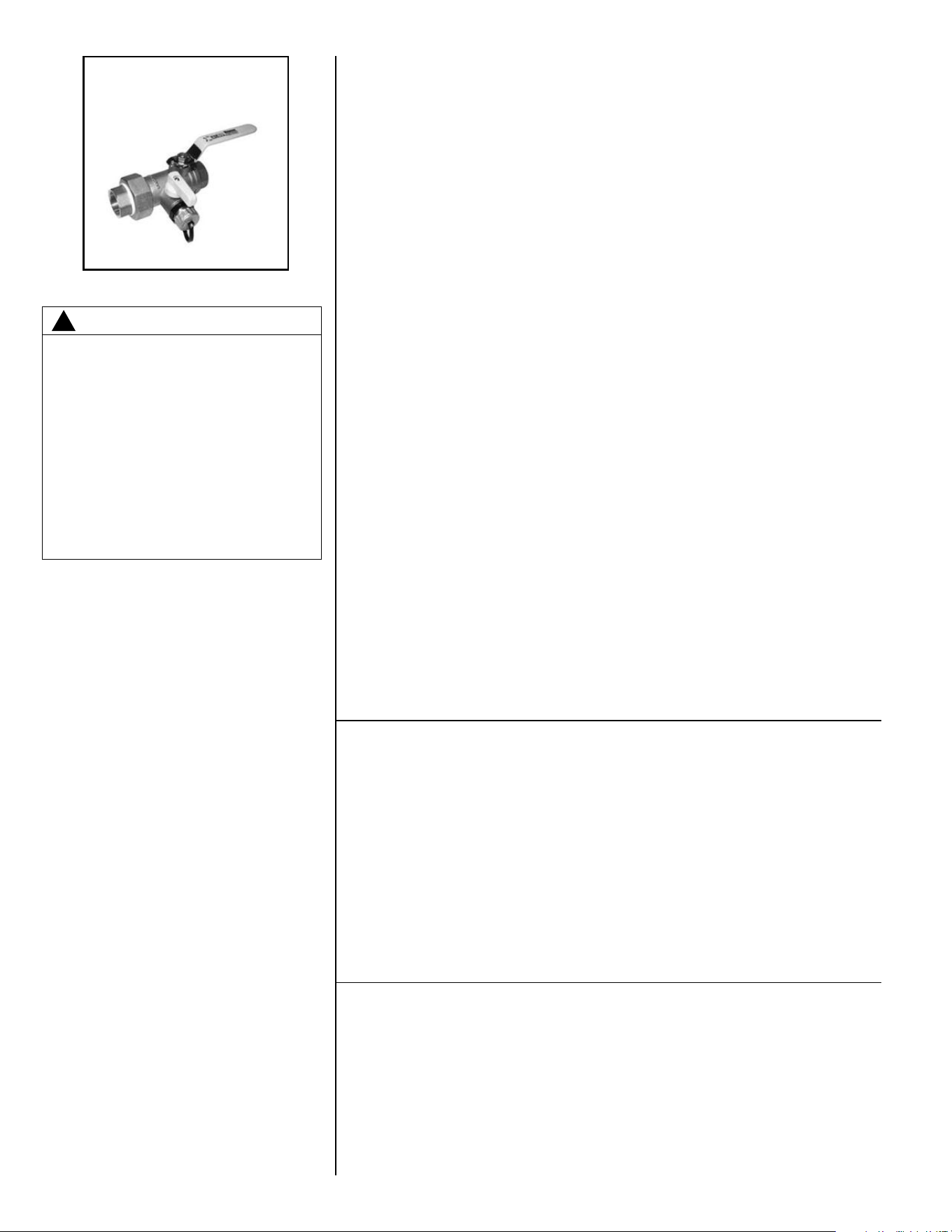
5. It is highly recommended that the H
2AC Rooftop unit be installed with isola-
tion/flushing valves (see illustration Figure 13, Webstone #40436 or similar) on
the inlet and outlet water connections to facilitate required periodic lime and
scale removal from the water-to-refrigerant heat exchanger.
6. Maximum equivalent length of water piping is to be in accordance with the procedure
shown in this manual. Consult the pressure loss tables for the values associated with
the required water fittings, valves, and straight lengths.
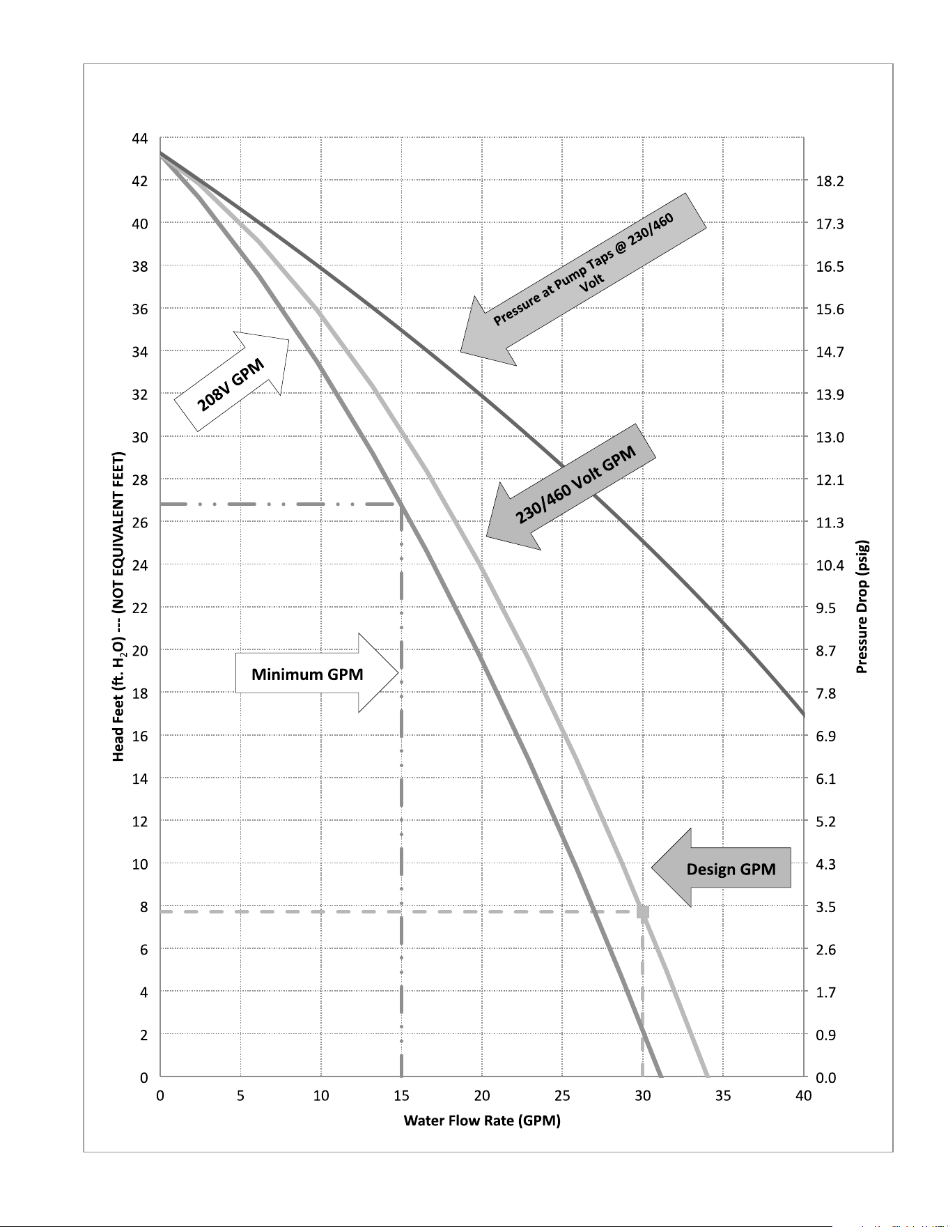
7. Use the H
2AC Rooftop Unit Water Flowrate vs. Water Pressure Drop graph to verify
that total system equivalent piping length will not result in less than the 15 GPM mini-
mum flow rate.
B. SYSTEM PRESSURE TEST AND START UP
1. Pressure test system complete system after all plumbing connections are made using
accepted plumbing leak test procedures.
2. The refrigerant-to-water heat exchanger and water pump housing will contain a
small amount of non-toxic RV-type water system anti-freeze left over from the
factory run test. Be certain to flush the unit and all connecting piping with fresh
water prior to start up and initial use.
3. Verify that air bleed valve in blower section on Hybrid unit is open during initial filling
with water. Air must be bled from the highest point in the system. If unit installation
results in a higher point than the integral air bleed valve, an additional valve needs to
be installed at that point.
4. Start unit and verify the correct sequence of operation.
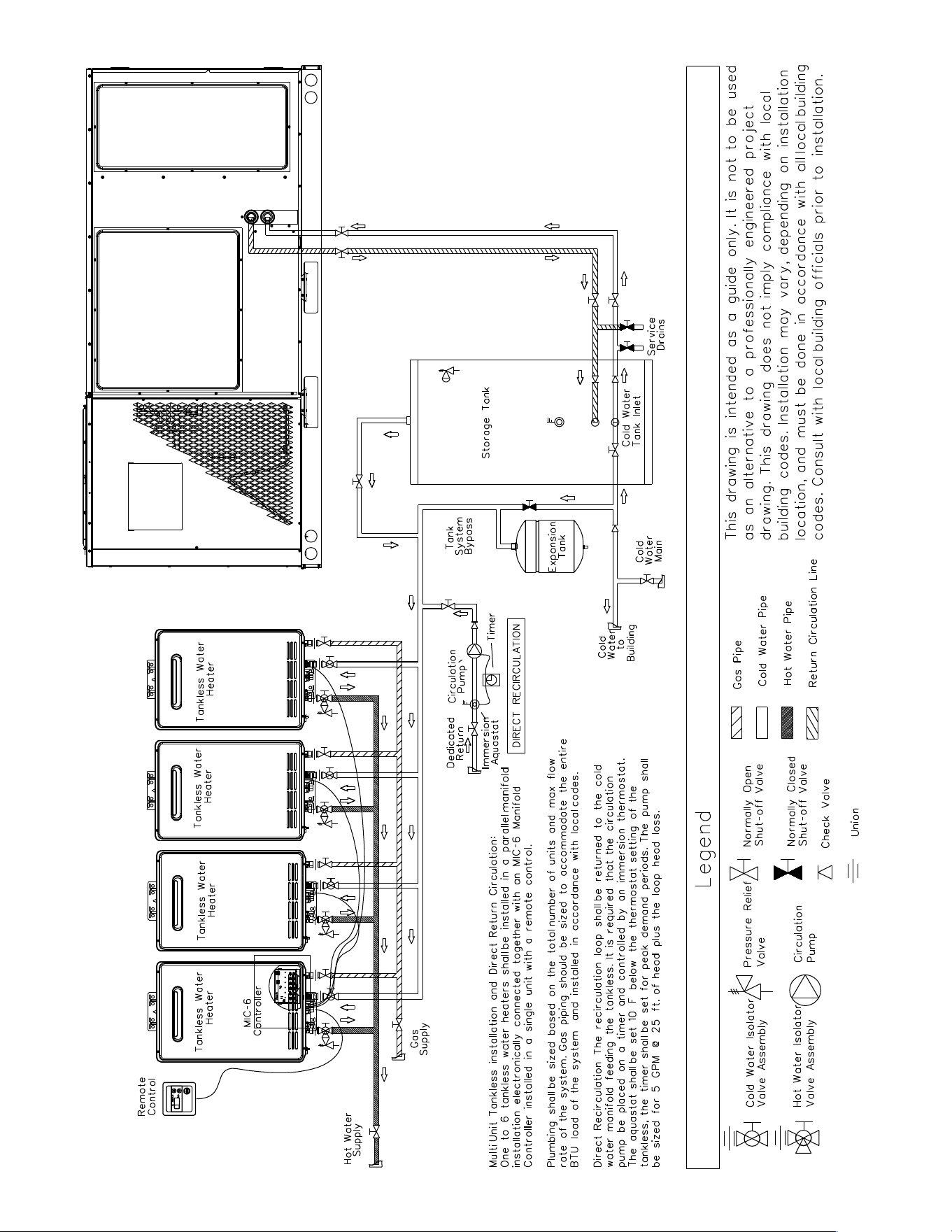
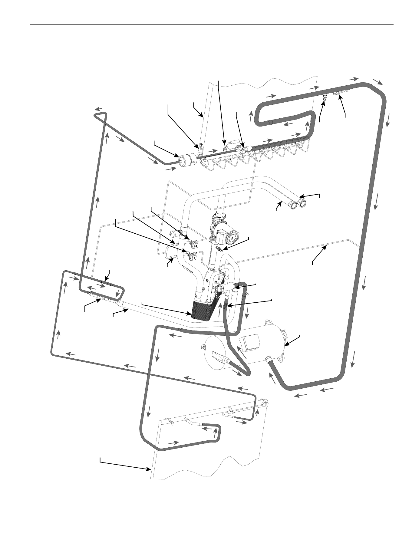
18
H2AC Rooftop Unit w/ circulation pump
19
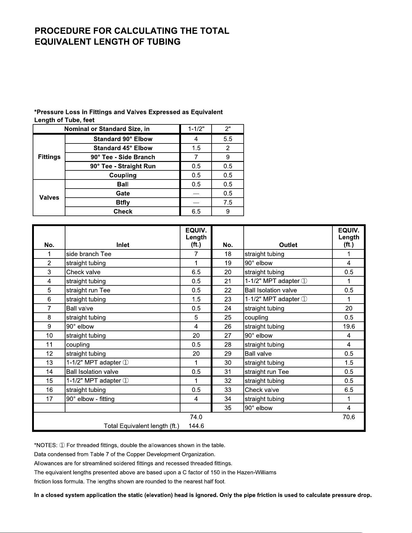
List all piping components from the storage tank to the H2AC rooftop unit
and back again. The equivalent length of straight tubing is the same as the
actual length. The equivalent length of fittings are obtained from the table
below. Sum all of the individual component lengths to find the Total
Equivalent Length.
20
Water Flow Rate (GPM) (15 GPM minimum) 15 20 25 30
Water Velocity using 1-1/2” Nom. Type L Copper Tubing (fps) 2.71 3.61 4.51 5.41
Available Pressure Head at Unit @ 230/460 Volts (Head ft.) 30.3 23.8 16.3 7.7
(psig) 13.1 10.3 7.1 3.3
Maximum Equivalent Feet of 1-1/2 Nom. Type L. Copper tubing (ft.) at 230/460V 1504 695 314 106
Available Pressure Head at Unit @ 208 Units (Head ft.) 26.8 19.5 11.3 2.2
(psig) 11.6 8.4 4.9 0.9
Maximum Equivalent Feet of 1-1/2” Nom. Type L Copper Tubing (ft.) @ 208 V 1332 569 218 30
FIGURE 12
ISOLATION/FLUSHING VALVE
21
H2AC Water Flowrate vs. Water Pressure Drop
22
XIV. LIME AND SCALE FLUSHING
XIV. PROCEDURE
Periodic flushing is required for the refrigerant-to-water heat exchanger contained in
the Rheem H
2AC Rooftop Unit to remove lime and scale buildup and to prevent
degradation of water heating performance. How often this is required depends on the
hardness of the water in your area and the run time in the water heating mode. The
below instructions provide a safe and effective means of removing the lime and scale
buildup in the heat exchanger. If you are not comfortable with the procedure, seek
out the assistance of a plumbing professional.
This procedure assumes that isolation/flushing valves have been installed on
the unit water inlet and outlet connections (see Figure 13). If the unit was
installed without valves, it is recommended that flushing be performed by a plumbing
professional.
Required items:
• Five gallon bucket
• Small circulation pump
• Hoses with connections suitable for the unit drain valves and pump.
• 2-3 gallons of food-grade white vinegar.
• The bucket, pump, and hoses can be ordered as Rheem flush kit RTG20124.
Instructions:
1. Turn off the electric supply to the unit.
2. Shut off the water supply to the unit using the isolation ball valves. Consult the
valve manufacturer’s instructions for specifics in using their valve assemblies.
3. Attach a short hose to the threaded fittings on each drain valve. Connect the
hose on the inlet valve to the outlet of a small circulation pump.
4. Pour approximately two to three gallons of food-grade white vinegar into the pail.
5. Place the inlet hose from the pump and the drain hose from the outlet valve on
the unit into the pail.
6. Open the drain valves and turn on the pump. Allow the vinegar solution to circu-
late for 45-60 minutes.
7. Turn off pump and drain vinegar from the heat exchanger. Close the inlet water
drain valve.
8. Open the inlet water supply shut off valve and allow fresh water to flush the heat
exchanger for at least five minutes to remove all traces of vinegar from the sys-
tem.
9. Close the outlet water drain valve and open the outlet water supply shut-off
valve.
10. Restore electrical power and verify correct unit operation.
XV. PRE-START CHECK
1. Is unit properly located and slightly slanted toward indoor condensate drain?
2. Is ductwork insulated, weatherproofed, with proper spacing to combustible mate-
rials?
3. Is air free to travel to and from outdoor coil? (See Figure 3.)
4. Is the wiring correct, tight, and according to unit wiring diagram?
5. Is unit grounded?
6. Are field supplied air filters in place and clean?
7. Do the outdoor fan and indoor blower turn freely without rubbing, and are they
tight on the motor shafts?
XVI. STARTUP
1. Turn thermostat to “OFF,” turn “on” power supply at disconnect switch.
2. Turn temperature setting as high as it will go.
3. Turn fan switch to “ON.”
4. Indoor blower should run. Be sure it is running in the right direction.
5. Turn fan switch to “AUTO.” Turn system switch to “COOL” and turn temperature
setting below room temperature. Unit should run in cooling mode.
6. Is outdoor fan operating correctly in the right direction?
7. Is compressor running correctly.
ONLY ELECTRIC HEATER KITS SUP-
PLIED BY THIS MANUFACTURER AS
DESCRIBED IN THIS PUBLICATION
HAVE BEEN DESIGNED, TESTED, AND
EVALUATED BY A NATIONALLY REC-
OGNIZED SAFETY TESTING AGENCY
FOR USE WITH THIS UNIT. USE OF ANY
OTHER MANUFACTURED ELECTRIC
HEATERS INSTALLED WITHIN THIS
UNIT MAY CAUSE HAZARDOUS CON-
DITIONS RESULTING IN PROPERTY
DAMAGE, FIRE, BODILY INJURY OR
DEATH.
▲WARNING
!
FIGURE 13
ISOLATION/FLUSHING VALVE
(WEBSTONE #41436 OR SIMILAR

23
Record the following after the unit has run some time.
A. Operating Mode _______________________________
B. Discharge Pressures (High) _____________PSIG [kPa]
C. Vapor Pressure at Compressors (Low)_____PSIG [kPa]
D. Vapor Line Temperature at Compressors ______°F [C°].
E. Indoor Dry Bulb __________________________°F [C°].
F. Indoor Wet Bulb__________________________°F [C°].
G. Outdoor Dry Bulb_________________________°F [C°].
H. Outdoor Wet Bulb ________________________°F [C°].
I. Voltage at Contactor ________________________Volts
J. Current at Contactors ______________________ Amps
K. Model Number_________________________________
L. Serial Number _________________________________
M.Location______________________________________
N. Owner _______________________________________
O. Date_________________________________________
8. Turn thermostat system switch to “HEAT.” Unit compressors should stop. Raise
temperature setting to above room temperature. Unit should run in heating mode
and auxiliary heaters, if installed, should come on.
9. Check the refrigerant charge using the instructions located on unit charging
chart. Replace service port caps. Service port cores are for system access only
and will leak if not tightly capped.
10. Adjust discharge air grilles and balance system.
11. Check ducts for condensation and air leaks.
12. Check unit for tubing and sheet metal rattles.
13. Instruct the owner on operation and maintenance.
14. Leave “INSTALLATION” and ”USE AND CARE“ instructions with owner.
XVII. OPERATION
COOLING MODE
NOTE: For this two-stage cooling and potable water heating unit, the water heating
section is located on the rear (second stage) refrigerant system. Because of the pres-
ence of the eSYNC control, the unit will always start the rear compressor first (lag
mode is permanently engaged), and then a Y2 call will energize the front compressor.
With thermostat in the cool mode, fan auto and the room temperature higher than the
thermostat setting:
A. Indoor blower contactor is energized through thermostat contact (G).
B. Compressor contactors are energized through thermostat contacts (Y1) & (Y2) and
pressure controls.
C. Economizer enthalpy control (if installed) controls operation of first-stage cooling
and positions fresh air damper to maintain mixed air temperature. Second-stage
cooling operates normally as required by second stage of thermostats.
D. The system will continue in cooling operation as long as all safety controls are
closed, until the thermostat is satisfied.
WATER HEATING MODE (H2AC SEQUENCE OF OPERATION)
1. On a call for cooling (“Y” from T’stat energized), unit always starts in air-cooled
condenser mode and runs for two minutes.
a. Liquid line solenoid from water-cooled heat exchanger is energized during this
time to expedite transfer of refrigerant from water-cooled condenser.
2. After two minutes water pump is energized for 60 seconds while water tempera-
ture is sampled by a thermistor.
a. If water pressure switch does not sense adequate pressure (5 psig), or water
inlet temperature is >95°F go to step 7.
3. If water pressure switch senses adequate pressure and water inlet temperature
is <95°F, unit switches to water-cooled condenser mode*.
a. Three-way valve is energized.
b. Outdoor fans are switched off.
c. Outdoor coil liquid line solenoid is energized for two minutes to expedite return
of liquid refrigerant in air-cooled condenser.
24
4. Unit operates in water-cooled condenser (water heating) mode until the call for
cooling ends, outlet water temperature reaches 138°F, or liquid line pressure
>565 psig.
5. The control will record the water inlet temperature when the refrigerant pressure
reaches 550 psig. The control will use this value minus 20°F for the H
2AC water
inlet restart temperature.
6. If termination of a call for cooling ends the water-cooled condenser (water heat-
ing) cycle, the unit will restart as described in item 1 above on the next call for
cooling.
7. If the water-cooled condenser (water heating) cycle terminates on water tempera-
ture rise (138°F) or pressure (>565 psig) and there is still a call for cooling, the
unit three-way valve switches back to the air-cooled condenser mode, turns on
the outdoor fans, and energizes the liquid line solenoid from the water-cooled
condenser for two minutes.
8. If a cooling (“Y”) call continues, return to Step 2 after a selectable delay (default
is ten minutes).
FAULTS/LOCKOUTS/MISC.
1. Low-temperature lockout - Occurs at 40°F for the water-cooled condenser
(water heating) mode. Unit will only operate in the air-cooled condenser mode
below 40°F.
2. Standard DDC control lockouts – High pressure control, low pressure control,
low ambient control, etc.
3. Three-way valve failure or water pump failure – A rapid rise in liquid line pres-
sure will occur. If liquid line pressure increases above 530 psig in less than one
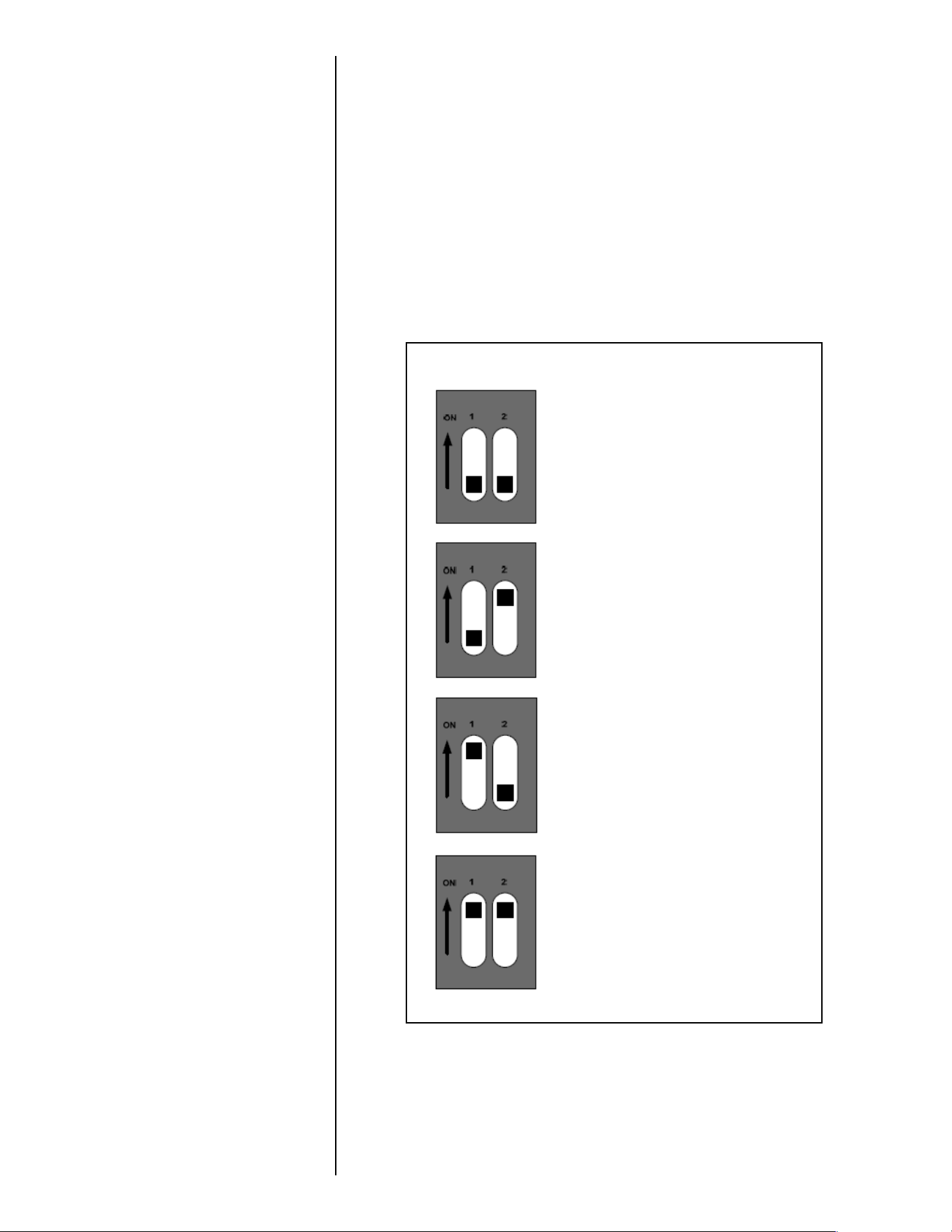
!
!
!
!
!
?(2@!A(5*2*(+5!BCC!
!DEE!54'(+<5!-F!>*+32451!
!
!
!
!
!
!
A(5*2*(+!:!*5!BG!&+<!A(5*2*(+!H!*5!BCC!
IEE!54'(+<5!-HE!>*+32451!
!
!
!
!
!
!
A(5*2*(+!:!*5!BCC!&+<!A(5*2*(+!H!*5!BG!
JEE!54'(+<5!-HF!>*+32451!
!
!
!
!
!
!
?(2@!A(5*2*(+5!BG!
H:EE!54'(+<5!-:E!>*+32451!
!
!
!
!
!
!
!
FIGURE 14

25
minute. If three of these trips occur during a call for cooling, a hard lockout of the
water heating mode will occur, but the unit will still function in the air-cooled con-
denser mode. The alarm is reset after a 24-hour delay.
4. Airside solenoid valve failure – shows up as an undercharge in the water heat-
ing mode. Four minutes after the 3-way valve has shifted, if subcooling less than
4° or superheat more than 25° is continuously measured for more than 30 sec-
onds, unit will return to air cooled mode. If this happens three times in a row with-
out a successful run of at least four minutes in the water heating mode, then a
hard lockout of the water heatiing mode will occur, but the unit will still function in
the air-cooled condenser mode. The alarm is reset after a 24-hour delay.
5. Freeze protection - If ambient is <35°F, water pump is energized until ambient is
>37°F.
6. Leak detection - If leak detector senses water, an alarm signal is sent to the
thermostat and waterside operation is locked out until leak detection ends.
Misc.
1. Water pump is energized once for 6 minutes every 24 hours to keep water from
stagnating in times of no cooling operation.
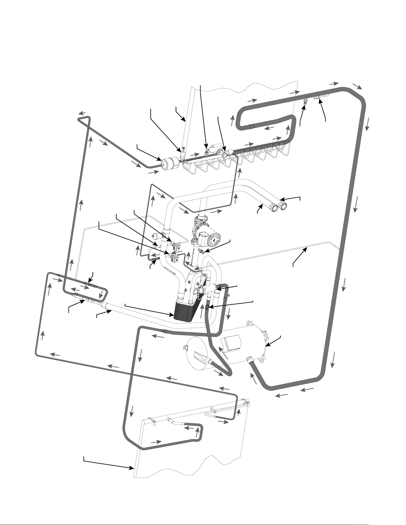
26
REFRIGERANT PIPING
SCHEMATIC H2AC
TXV
FILTER/DRIER
CHECK
VALVE
AIR-COOLED
CONDENSER COIL
COMPRESSOR
3-WAY
VALVE
WATER-COOLED
CONDENSER
EVAPORATOR
COIL
“WATER”
SOLENOID
“AIR”
SOLENOID
WATER OUT
WATER IN
LOW AMBIENT
CONTROL
REFRIGERANT
LIQUID LINE
PRESSURE
SENSOR
REFRIGERANT LOW
PRESSURE SENSOR
REFRIGERANT LOW
PRESSURE SWITCH
CHECK
VALVE
CHECK
VALVE
CHECK
VALVE
HIGH
PRESSURE
SWITCH
WATER
PRESSURE
SENSOR
OIL RETURN MODE - (2 min)
Refrigerant is removed from idle Water-cooled
Condenser (flat plate heat exchanger) via
“Water” Solenoid.
REFRIGERANT
STORAGE
RECEIVER
REFRIGERANT
DUMP LINE
27
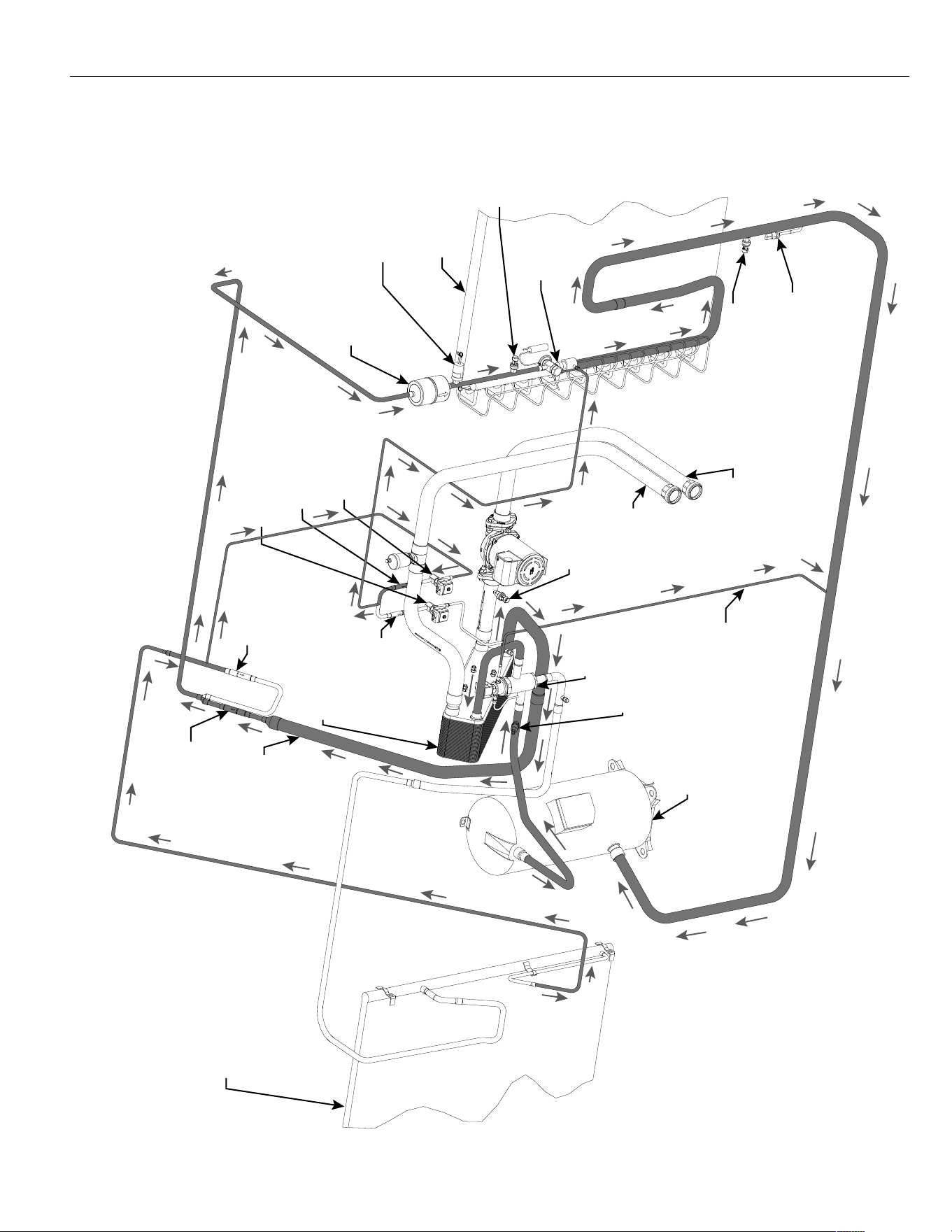
REFRIGERANT PIPING
SCHEMATIC H2AC
TXV
FILTER/DRIER
CHECK
VALVE
AIR-COOLED
CONDENSER COIL
COMPRESSOR
3-WAY
VALVE
WATER-COOLED
CONDENSER
EVAPORATOR
COIL
“WATER”
SOLENOID
“AIR”
SOLENOID
WATER OUT
WATER IN
LOW AMBIENT
CONTROL
REFRIGERANT
LIQUID LINE
PRESSURE
SENSOR
REFRIGERANT LOW
PRESSURE SENSOR
REFRIGERANT LOW
PRESSURE SWITCH
CHECK
VALVE
CHECK
VALVE
CHECK
VALVE
HIGH
PRESSURE
SWITCH
WATER
PRESSURE
SENSOR
WATER HEATING MODE - (first 2 min)
Water is heated by flat plate heat exchanger
(Water-cooled Condenser). Refrigerant is removed
from idle Air-cooled Condenser Coil via “Air” Solenoid.
REFRIGERANT
STORAGE
RECEIVER
REFRIGERANT
DUMP LINE
28
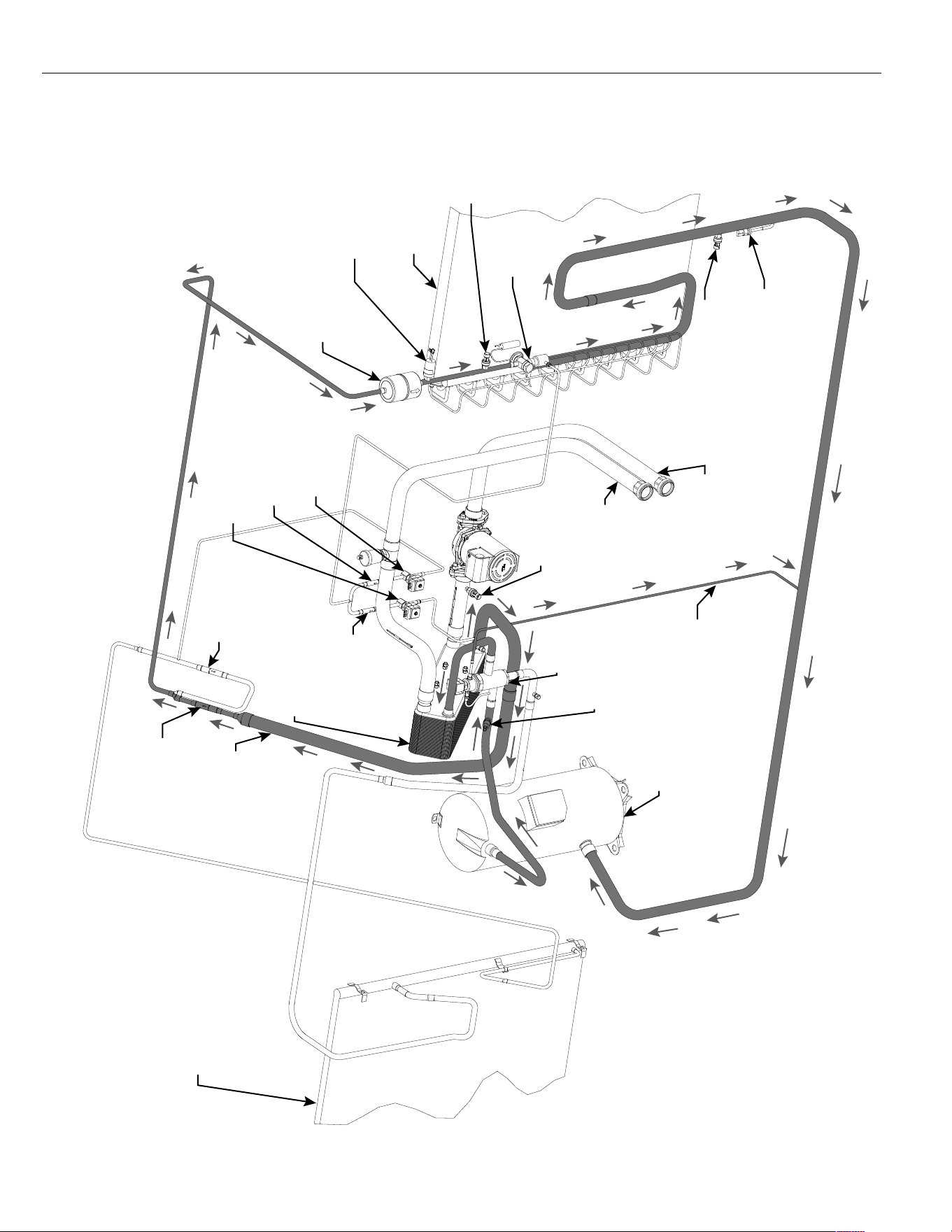
REFRIGERANT PIPING
SCHEMATIC H2AC
TXV
FILTER/DRIER
CHECK
VALVE
AIR-COOLED
CONDENSER COIL
COMPRESSOR
3-WAY
VALVE
WATER-COOLED
CONDENSER
EVAPORATOR
COIL
“WATER”
SOLENOID
“AIR”
SOLENOID
WATER OUT
WATER IN
LOW AMBIENT
CONTROL
REFRIGERANT
LIQUID LINE
PRESSURE
SENSOR
REFRIGERANT LOW
PRESSURE SENSOR
REFRIGERANT LOW
PRESSURE SWITCH
CHECK
VALVE
CHECK
VALVE
CHECK
VALVE
HIGH
PRESSURE
SWITCH
WATER
PRESSURE
SENSOR
WATER HEATING MODE - (after 2 min)
Water is heated by flat plate heat exchanger
(Water-cooled Condenser).
REFRIGERANT
STORAGE
RECEIVER
REFRIGERANT
DUMP LINE
29
REFRIGERANT PIPING
SCHEMATIC H2AC
TXV
FILTER/DRIER
CHECK
VALVE
AIR-COOLED
CONDENSER COIL
COMPRESSOR
3-WAY
VALVE
WATER-COOLED
CONDENSER
EVAPORATOR
COIL
“WATER”
SOLENOID
“AIR”
SOLENOID
WATER OUT
WATER IN
LOW AMBIENT
CONTROL
REFRIGERANT
LIQUID LINE
PRESSURE
SENSOR
REFRIGERANT LOW
PRESSURE SENSOR
REFRIGERANT LOW
PRESSURE SWITCH
CHECK
VALVE
CHECK
VALVE
CHECK
VALVE
HIGH
PRESSURE
SWITCH
WATER
PRESSURE
SENSOR
WATER HEATING DELAY MODE -
(10 min adjustable)
Normal Air Conditioning Mode
REFRIGERANT
STORAGE
RECEIVER
REFRIGERANT
DUMP LINE
30
HEATING MODE
With the thermostat in heat mode, fan on auto, and the room temperature lower than
the thermostat setting, the indoor blower contactor is energized through thermostat
contact (G).
XVIII. AUXILIARY HEAT
In the heating mode, the thermostat will energize one or more supplementary resist-
ance heaters.
REPLACEMENT PARTS
Contact your local distributor for a complete parts list.
CHARGE INFORMATION
Refer to the appropriate charge chart on the unit, or in this booklet.
TROUBLESHOOTING
Refer to the troubleshooting chart included in this manual.
WIRING DIAGRAMS
Refer to the appropriate wiring diagram included in this manual.
ONLY ELECTRIC HEATER KITS SUP-
PLIED BY THIS MANUFACTURER AS
DESCRIBED IN THIS PUBLICATION
HAVE BEEN DESIGNED, TESTED, AND
EVALUATED BY A NATIONALLY REC-
OGNIZED SAFETY TESTING AGENCY
FOR USE WITH THIS UNIT. USE OF ANY
OTHER MANUFACTURED ELECTRIC
HEATERS INSTALLED WITHIN THIS
UNIT MAY CAUSE HAZARDOUS CON-
DITIONS RESULTING IN PROPERTY
DAMAGE, FIRE, BODILY INJURY OR
DEATH.
▲WARNING
!
▲WARNING
!
ONLY ELECTRIC HEATER KITS SUPPLIED BY THIS MANUFACTURER AS
DESCRIBED IN THIS PUBLICATION HAVE BEEN DESIGNED, TESTED, AND
EVALUATED FOR USE WITH THIS UNIT. USE OF ANY OTHER MANUFAC-
TURED ELECTRIC HEATERS INSTALLED WITHIN THIS UNIT MAY CAUSE HAZ-
ARDOUS CONDITIONS RESULTING IN PROPERTY DAMAGE, FIRE, BODILY
INJURY OR DEATH.
31
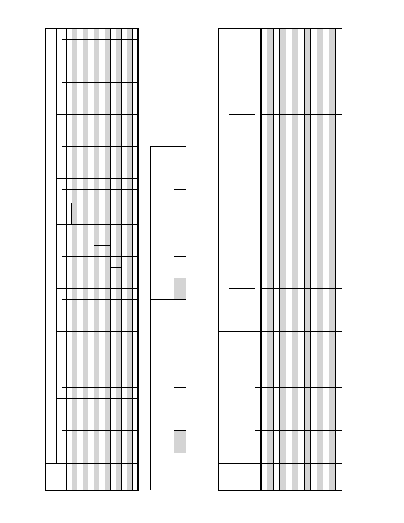
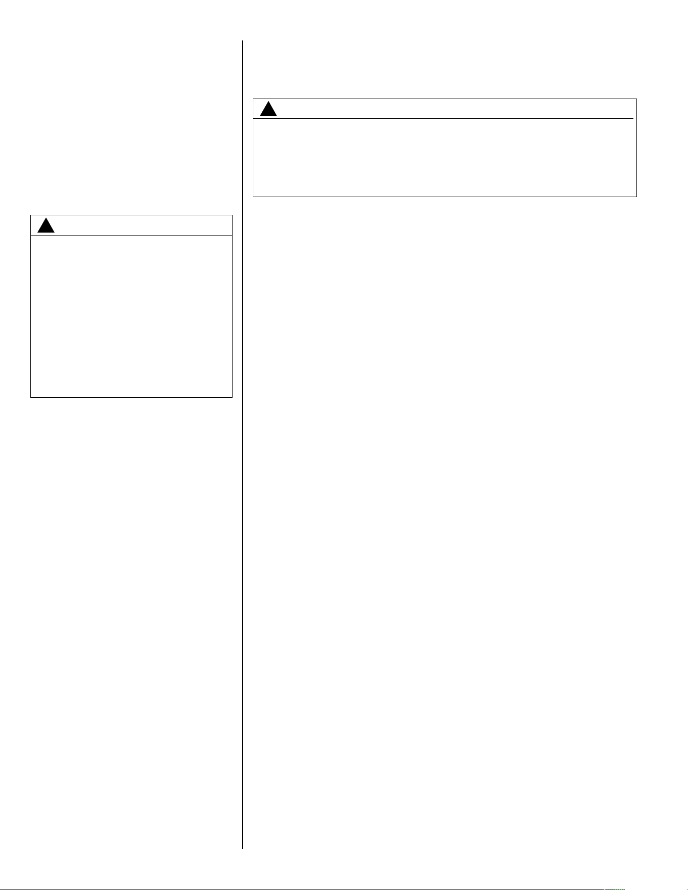
XIX. HEATER KIT CHARACTERISTICS
XXI. AUXILIARY HEATER KITS CHARACTERISTICS AND APPLICATION
XXI. (15 & 20 TON MODELS)
!"#"$%&'()" *+,#-./ $$$$$ $$$$$ $$$$$ $$$$$ 00100 2(1&(( 2(1&(( $$$$$ $$$$$ 00100 2(1&(( 2(1&((
)34() & &5651&264 526&718969 5(15864 00100 2(1&(( 2(1&(( 9(19' 9(18( 00100 2(1&(( 2(1&((
)35() 4 4'6'17'67 2'6491&7(688 026212464 &&01&74 &491&49 &9(1&9( &((1&&8 &((1&49 00100 2(1&(( 2(1&((
)38() 4 576419069 &5067'1&286&8
&&2621&7'67
&801&2( &091&09 4((14(( &9(1&07 &9(1&09 00100 2(1&(( 2(1&((
)309) 4 9510&62 &'56441459642
&526'1&046'
4(51477 4491449 49(149( &''14&0 4((1449 00100 2(1&(( 2(1&((
!"#"$%&'(): *+,#-./ $$$$$ $$$$$ $$$$$ $$$$$ '&1'& 2(1&(( 2(1&(( $$$$$ $$$$$ '&1'& 2(1&(( 2(1&((
)34() & &5651&264 526&718969 5(15864 '&1'& 2(1&(( 2(1&(( 9(19' 9(18( '&1'& 2(1&(( 2(1&((
)35() 4 4'6'17'67 2'6491&7(688 026212464 &4&1&78 &491&49 &9(1&9( &((1&&8 &((1&49 '&1'& 2(1&(( 2(1&((
)38() 4 576419069 &5067'1&286&8
&&2621&7'67
&0&1&25 &091&09 4((14(( &9(1&07 &9(1&09 '&1'& 2(1&(( 2(1&((
)309) 4 9510&62 &'56441459642
&526'1&046'
4(21470 4491449 49(149( &''14&0 4((1449 '&1'& 2(1&(( 2(1&((
!"#"$%&'(%" *+,#-./ $$$$$ $$$$$ $$$$$ $$$$$ 5( 5919( $$$$$ $$$$$ $$$$$ 5( 5919( $$$$$
)34(% & &264 8969 476& 5( 5919( $$$$$ 42 7( 5( 5919( $$$$$
)35(% 4 7'65 &7& 5864 88 0(10( $$$$$ 9' 8( 5( 5919( $$$$$
)38(% 4 9068 &2869 8267 29 &((1&(( $$$$$ '0 2( 5( 5919( $$$$$
)309% 4 04 459687 '868 &&0 &491&49 $$$$$ &(2 &&( 5( 5919( $$$$$
!"#"$%&'(%: *+,#-./ $$$$$ $$$$$ $$$$$ $$$$$ 54 5919( $$$$$ $$$$$ $$$$$ 54 5919( $$$$$
)34(% & &264 8969 476& 54 5919( $$$$$ 42 7( 54 5919( $$$$$
)35(% 4 7'65 &7& 5864 82 0(10( $$$$$ 9' 8( 54 5919( $$$$$
)38(% 4 9068 &2869 8267 2' &((1&(( $$$$$ '0 2( 54 5919( $$$$$
)309% 4 04 459687 '868 &&2 &491&49 $$$$$ &(2 &&( 54 5919( $$$$$
!"#$%&"'()"*%
+,-.("*/%
0123
456'%&)''6#*%7'8*6(*"56%965"(6%
:";6
!"#$<!.=$%>%
012%3
!"#$<!.=$%>%
012%3
!"#$<!.=$%>%
012%3
!"#$<!.=$%>%
012%3
!"#$%&?*$%
+,-.("*/%0123
012%34@AB%ACDEE%7C+:EB%F2%CGB%+HIJ@J+DK%E@E&ADJ&%CE+AED%LJA:%&C+D+&AEDJ:AJ&:%+M9%+77@J&+AJ4M
:"#NO6%78P6'%:)--O/%Q8'%R8*S%H#"*%.#T%C6.*6'%L"*
:6-.'.*6%78P6'%:)--O/%Q8'%R8*S%H#"*%.#T%C6.*6'%L"*
DCEE!%!8T6O%M),U6'
C6.*6'%L"*
+"'%&8#T"*"8#6'
C6.*6'%L"*
+"'%&8#T"*"8#6'
M8$%8Q%
:6V)6#(6%
:*6-W
D.*6T%C6.*6'%
?X%>%012%3
C6.*6'%
LRAH<C'%>%
012%3
C6.*6'%
+,-$%>%
012%3
H#"*%!"#$%&?*$%
+,-.("*/%>%012%
3
456'%&)''6#*%7'8*6(*"56%965"(6%
:";6
!.=$%Y)W6%
:";6%0123
!"#$%&"'()"*%
+,-.("*/%
Z21<Z023
456'%&)''6#*%7'8*6(*"56%965"(6%
:";6
!"#$<!.=$%>%
Z21%3
!"#$<!.=$%>%
Z02%3
!"#$<!.=$%>%
Z21%3
!"#$<!.=$%>%
Z02%3
!"#$%&?*$%
+,-.("*/%
Z21<Z023
Z21<Z02%34@AB%ACDEE%7C+:EB%F2%CGB%+HIJ@J+DK%E@E&ADJ&%CE+AED%LJA:%&C+D+&AEDJ:AJ&:%+M9%+77@J&+AJ4M
:"#NO6%78P6'%:)--O/%Q8'%R8*S%H#"*%.#T%C6.*6'%L"*
:6-.'.*6%78P6'%:)--O/%Q8'%R8*S%H#"*%.#T%C6.*6'%L"*
DCEE!%!8T6O%M),U6'
C6.*6'%L"*
+"'%&8#T"*"8#6'
C6.*6'%L"*
+"'%&8#T"*"8#6'
DI[[\%C6.*6'%
L"*%M8,"#.O%
?X
M8$%8Q%
:6V)6#(6%
:*6-W
D.*6T%C6.*6'%
?X%>%Z21<Z02%
3
C6.*6'%
LRAH<C'%>%
Z21<Z02%3
C6.*6'%
+,-$%>%
Z21<Z02%3
H#"*%!"#$%&?*$%
+,-.("*/%>%
Z21<Z02%3
456'%&)''6#*%7'8*6(*"56%965"(6%
:";6
!.=$%Y)W6%
:";6%
Z21<Z023
32
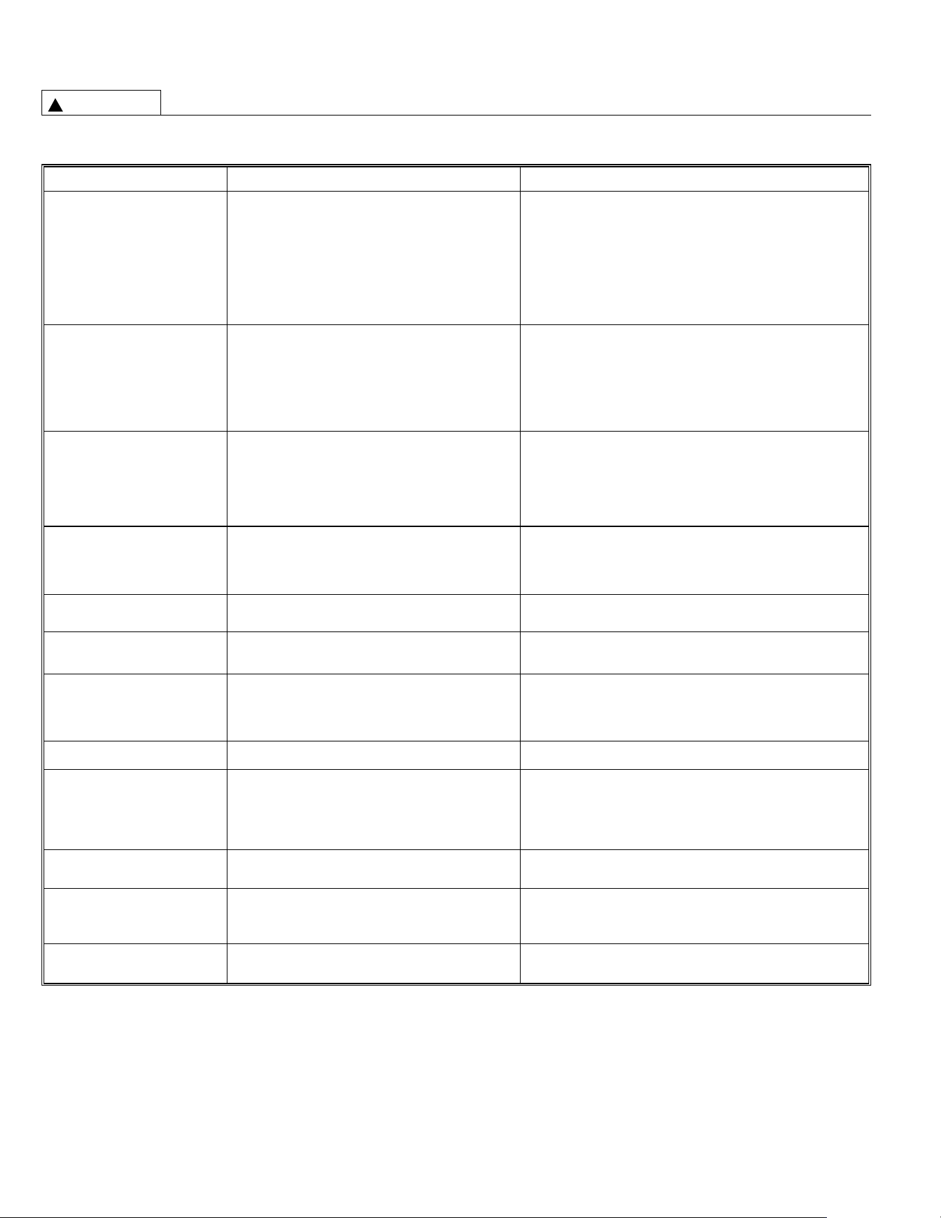
WARNING
!
TROUBLE SHOOTING CHART
DISCONNECT ALL POWER TO UNIT BEFORE SERVICING. CONTACTOR MAY BREAK ONLY ONE SIDE. FAILURE
TO SHUT OFF POWER CAN CAUSE ELECTRICAL SHOCK RESULTING IN PERSONAL INJURY OR DEATH.
SYMPTOM POSSIBLE CAUSE REMEDY
Unit will not run • Power off or loose electrical connection • Check for correct voltage at compressor contactor in control
box
• Thermostat out of calibration-set too high • Reset
• Defective contactor • Check for 24 volts at contactor coil - replace if contacts are
open
• Blown fuses • Replace fuses
• Transformer defective • Check wiring-replace transformer
• High pressure control open (if provided) • Reset-also see high head pressure remedy-
• Interconnecting low voltage wiring damaged • Replace thermostat wiring
Condenser fan runs, compressor • Run capacitor defective (single phase only) • Replace
doesn’t • Loose connection • Check for correct voltage at compressor -
check & tighten all connections
• Compressor stuck, grounded or open motor winding • Wait at least 2 hours for overload to reset.
open internal overload. If still open, replace the compressor.
• Low voltage condition At compressor terminals, voltage must be within 10% of rating
plate volts when unit is operating.
Insufficient cooling • Improperly sized unit • Recalculate load
• Improper airflow • Check - should be approximately 400 CFM per ton.
• Incorrect refrigerant charge • Charge per procedure attached to unit service panel.
• Air, non-condensibles or moisture in system • Recover refrigerant, evacuate & recharge, add filter drier
• Incorrect voltage • At compressor terminals, voltage must be within 10% of rating
plate volts when unit is operating.
Compressor short cycles • Incorrect voltage • At compressor terminals, voltage must be ± 10% of
nameplate marking when unit is operating.
• Defective overload protector • Replace - check for correct voltage
• Refrigerant undercharge • Add refrigerant
Registers sweat • Low evaporator airflow • Increase speed of blower or reduce restriction - replace air
filter
High head-low vapor pressures • Restriction in liquid line, expansion device or filter drier • Remove or replace defective component
• TXV does not open • Replace TXV
High head-high or normal vapor • Dirty condenser coil • Clean coil
pressure - Cooling mode • Refrigerant overcharge • Correct system charge
• Condenser fan not running • Repair or replace
• Air or non-condensibles in system • Recover refrigerant, evacuate & recharge
Low head-high vapor pressures • Defective Compressor valves • Replace compressor
Low vapor - cool compressor - • Low evaporator airflow • Increase speed of blower or reduce restriction - replace air
iced evaporator coil filter
• Operating below 65°F outdoors • Add Low Ambient Kit
• Moisture in system • Recover refrigerant - evacuate & recharge - add filter drier
• Dirty evaporator coil, bent fins • Clean evaporator coil, straighten fins
High vapor pressure • Excessive load • Recheck load calculation
• Defective compressor • Replace
Fluctuating head & vapor • TXV hunting • Check TXV bulb clamp - check air distribution on coil - replace
pressures TXV
• Air or non-condensibles in system • Recover refrigerant, evacuate & recharge
Gurgle or pulsing noise at • Air or non-condensibles in system • Recover refrigerant, evacuate & recharge
expansion device or liquid line

33
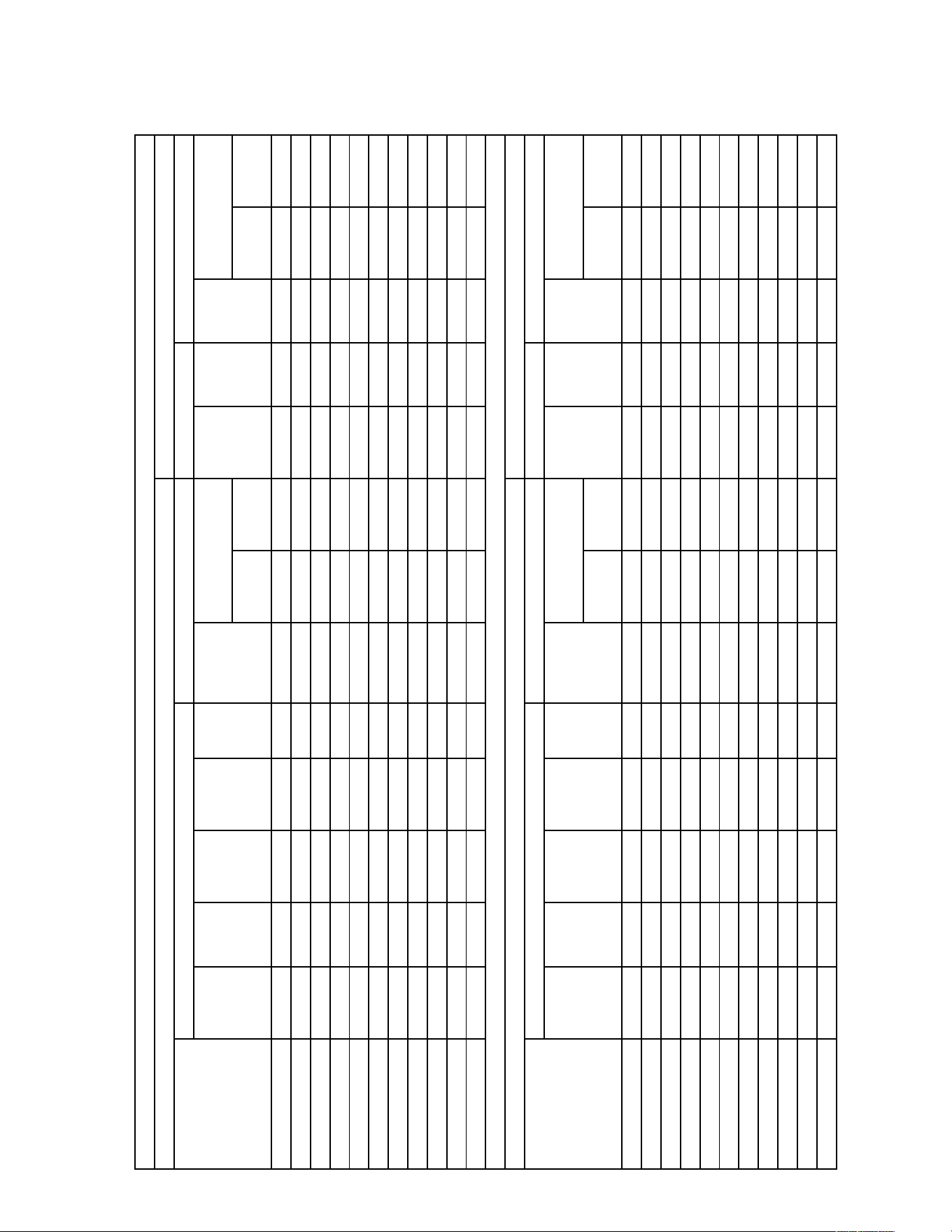
XX. H2AC ROOFTOP UNIT ALARMS AND TROUBLESHOOTING
Alarm Designation MODBUS "Current Alarm" Code Description Troubleshooting Information
The sensor in the water heating (hybrid)
section of the unit has detected a water leak
and stopped water heating operation. A relay
output for an optional field-installed water
shutoff valve is energized.
> Check for loose or defective air vent valve on water
discharge line in water heating section.
> Check for water pump seal leakage.
> Check that sensor is installed correctly on control.
> Replace the sensor.
No alarm is set. The water sensor measures
potable water pressure in the water heating
section. If the water pressure is below 5 PSIG,
water heating operation will not begin. If the
sensor becomes unavailable, water heating
operation terminates. The unit can continue
to operate in cooling mode.
> Check that sensor is correctly installed on control.
> The sensor has three wires that attach to the hybrid
control. Check for 5VDC between the outer terminals.
If
5VDC is not present, replace the hybrid control.
> Replace the sensor.
The outdoor ambient sensor on the RTU-C has
detected outdoor ambient temperature
below 35°F. The water pump is energiced
continuously until the outdoor ambient
temperature rises above 38°F.
> Check that sensor is installed correctly on control.
> Check sensor location.
> Replace the sensor.
At the beginning of each water heating cycle,
if the high pressure sensor value exceeds 530
PSIG after 3 seconds but before 60 seconds
are elapsed, an alarm is set.
> Check water pump operation, shut-off valves, etc. for adequate
water flow.
> Check for 24VAC at control transformer
> Check for 24VAC at hybrid unit 3-way refrigerant valve.
> Increase water sample delay time using DIP switches on hybrid
control.
> Replace 3-way refrigerant valve if it fails to shift.
The water pump is energzed continuously
until the sensor becomes available.
> Extreme temperatures.
> Check that sensor is installed correctly.
> Replace the sensor.
If the sensor becomes unavailable, an alarm
will be set and water heating operation
terminates. Unit can continue to operate in
cooling mode.
> Extreme temperatures.
> Check that sensor is installed correctly.
> Replace the sensor.
If the sensor becomes unavailable, an alarm
will be set and water heating operation
terminates. Unit can continue to operate in
cooling mode.
> Extreme temperatures.
> Check that sensor is installed correctly.
> Replace the sensor.
If both sensors becomes unavailable, an
alarm will be set and water heating operation
terminates. Unit can continue to operate in
cooling mode.
> Extreme temperatures.
> Check that sensor is installed correctly.
> Replace the sensors.
The high pressure sensor measures liquid
refrigerant pressure. If the sensor becomes
unavailable, water heating operation
terminates and an alarm is set. Unit can
continue to operate in cooling mode.
> Check that sensor is correctly installed on control.
> The sensor has three wires that attach to the hybrid
control. Check for 5VDC between the outer terminals.
If
5VDC is not present, replace the hybrid control.
> Replace the sensor.
The low pressure sensor measures liquid
refrigerant pressure. If the sensor becomes
unavailable, water heating operation
terminates and an alarm is set. Unit can
continue to operate in cooling mode.
> Check that sensor is correctly installed on control.
> The sensor has three wires that attach to the hybrid
control. Check for 5VDC between the outer terminals.
If
5VDC is not present, replace the hybrid control.
> Replace the sensor.
If alarms 105, 115, 116, 117, or 118 are
initiated more than 3 times from unit power-
up, an alarm is set and water heating mode is
terminated until the alarm is cleared. The
lockout fault can only be cleared by
removing power to the unit or by sending a
"Clear All Alarms" command through the BAS
network.
> Check individual alarms.
If, 4 minutes after the 3-way valve has shifted,
low subcooling was continuously measured
for more than 30 seconds during the water
heating mode an alarm is set. Unit operation
continues.
> If low subcooling occurs after exiting the air conditioning
mode, check wiring and verify operation of outdoor
refrigerant (air side) solenoid.
> Check location of liquid line temperature sensor.
> Verify correct refrigerant charge.
Low Subcooling - air conditioning
mode
If, 4 minutes after the 3-way valve has shifted,
low subcooling was continuously measured
for more than 30 seconds during the air
conditining mode an alarm is set. Unit
operation continues.
> If low subcooling occurs after exiting the water heating
mode, check wiring and verify operation of flat plate heat
exchanger (water side) solenoid.
> Check location of liquid line temperature sensor.
> Verify correct refrigerant charge.
High Superheat - water heating mode
If, 4 minutes after the 3-way valve has shifted,
high superheat was continuously measured
for more than 30 seconds during the water
heating mode an alarm is set. Unit operation
continues.
> High internal building load.
> Expansion valve is not operating correctly.
High Superheat - air conditioning
heating mode
If, 4 minutes after the 3-way valve has shifted,
high superheat was continuously measured
for more than 30 seconds during the air
conditioning mode an alarm is set. Unit
operation continues.
> If high superheat occurs after exiting the water heating
mode, check wiring and verify operation of flat plate heat
exchanger (water side) solenoid.
> High internal building lode.
> Expansion valve is not operating correctly.
H
2AC Rooftop Unit Water Leakage
102
103
104
105
106
107
108
109
110
111
112
115
116
117
118
H
2AC Rooftop Unit Low Water Pressure
H
2AC Rooftop Unit Freeze Protection Mode
H
2AC Rooftop Unit Solenoid Fault
H
2AC Rooftop Unit Ambient Sensor Fault
H
2AC Rooftop Unit Water Inlet Sensor Fault
H
2AC Rooftop Unit Water Outlet Sensor Fault
H
2AC Rooftop Unit Water Inlet and Outlet
Sensor Fault
H
2AC Rooftop Unit High Pressure Sensor Fault
H
2AC Rooftop Unit Low Pressure Sensor Fault
H
2AC Rooftop Unit Lockout Fault
H
2AC Rooftop Unit Low Subcooling - water
heating mode
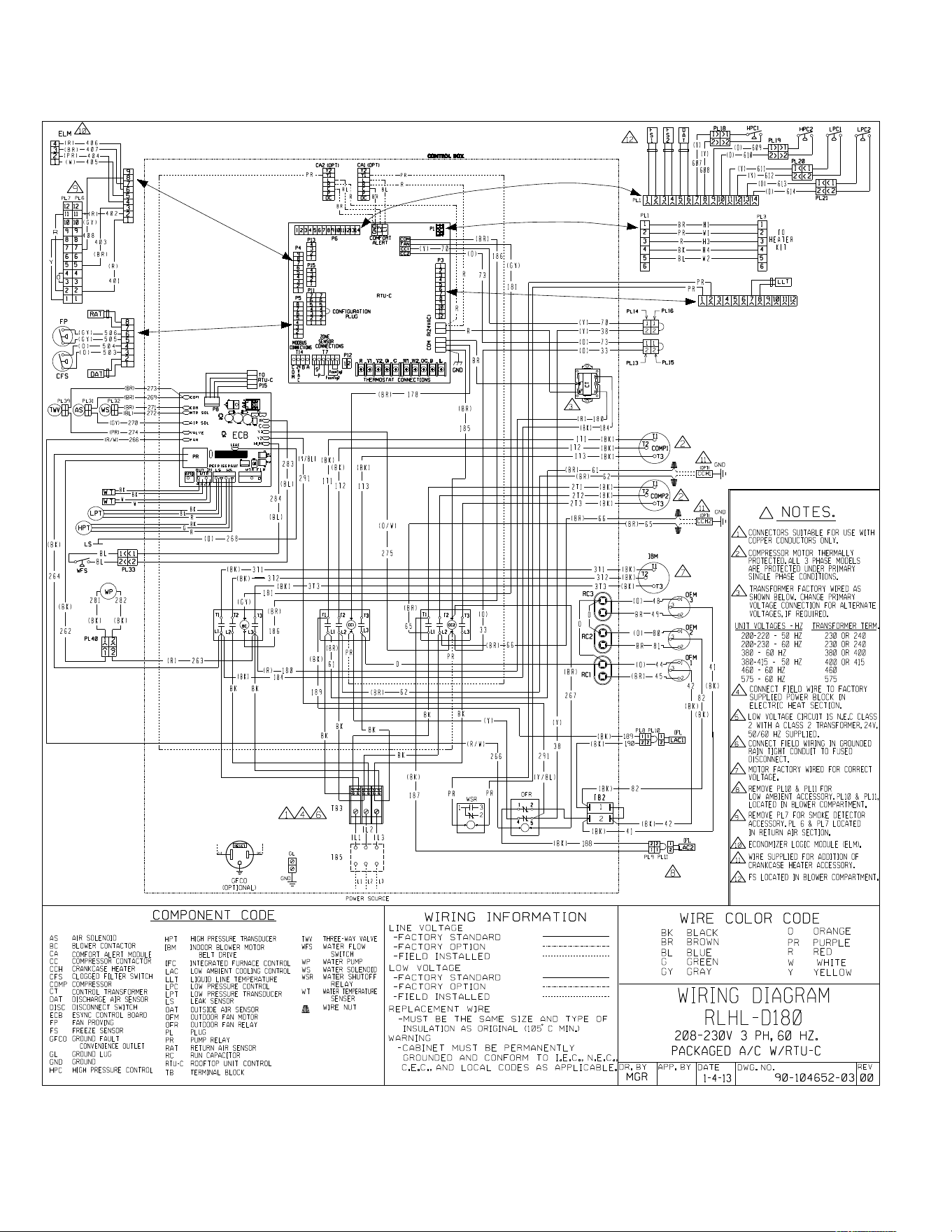
34
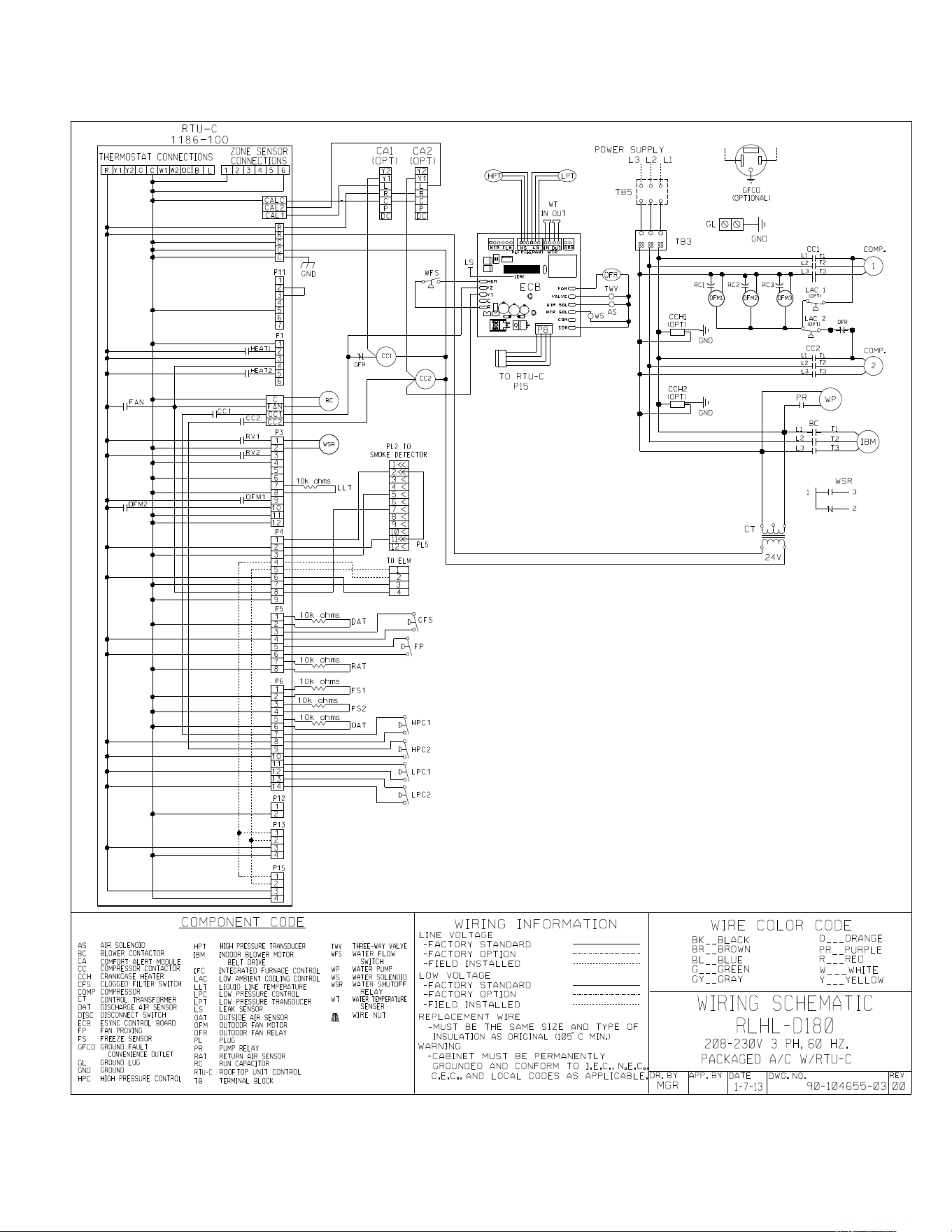
35
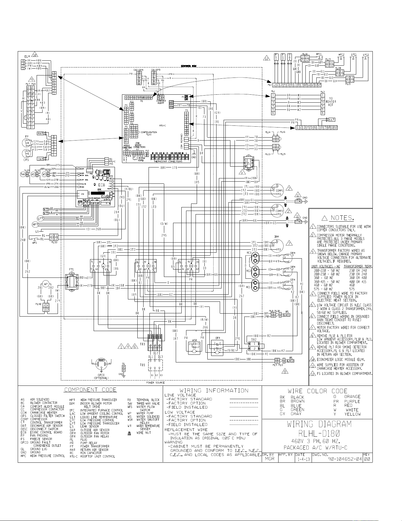
36

37
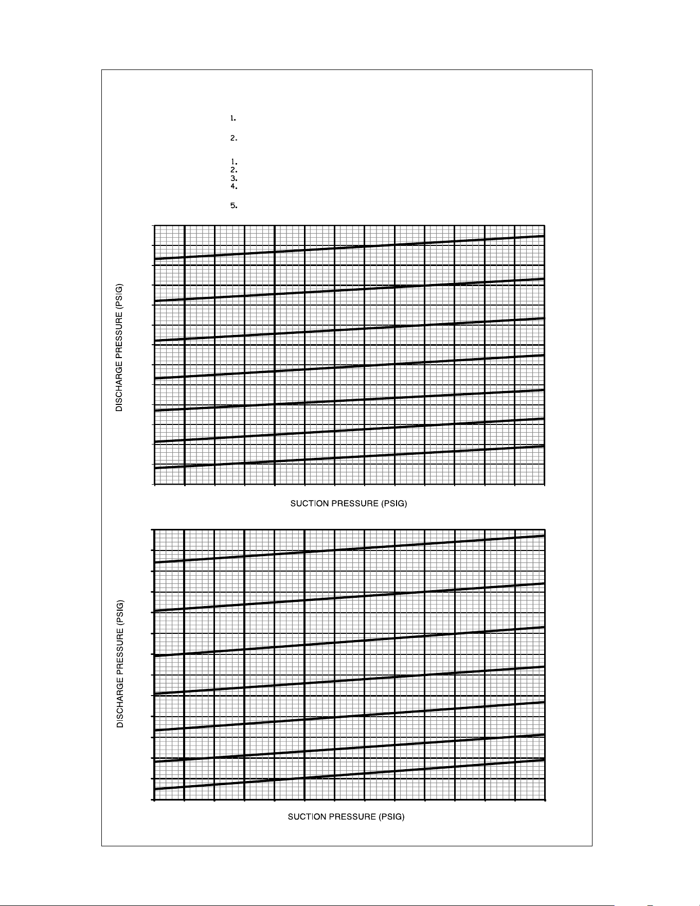
38
RLHL SERIES – 15 TON
SYSTEM CHARGE CHART - REFRIGERANT 410A
15 TON, CIRCUITS 1 & 2
CIRCUIT 1
CIRCUIT 2
92-103943-05-00
BOTH COMPRESSORS MUST BE OPERATING BEFORE CHECKING
REFRIGERANT CHARGE.
BEFORE FINAL REFRIGERANT CHECK!
RETURN AIR TEMPERATURE MUST BE WITHIN COMFORT CONDITIONS
MEASURE PRESSURE AT COMPRESSOR SUCTION AND DISCHARGE.
MEASURE OUTDOOR AMBIENT TO UNIT.
PLACE (X) ON CHART WHERE SUCTION AND DISCHARGE INTERSECT.
IF (X) IS BELOW OUTDOOR AMBIENT LINE, ADD CHARGE AND REPEAT
STEPS 1-3.
IF (X) IS ABOVE OUTDOOR AMBIENT LINE, RECOVER EXCESS CHARGE
AND REPEAT STEPS 1-3.
CAUTION:
INSTRUCTIONS:
OUTDOOR AMBIENT (F, DB)
OUTDOOR AMBIENT (F, DB)
115
105
95
85
75
65
55
175
200
225
250
275
300
325
350
375
400
425
450
475
500
100 105 110 115 120 125 130 135 140 145 150 155 160 165
115
105
95
85
75
65
55
200
225
250
275
300
325
350
375
400
425
450
475
500
525
100 105 110 115 120 125 130 135 140 145 150 155 160 165

39

40 CM 0613