92-23577-77-08
SUPERSEDES 92-23577-77-07
PACKAGE HEAT PUMPS
RJNL 13 SEER SERIES (3-5 TON)
RJNL 11.0 EER SERIES (6 TON)
RJPL 14 SEER SERIES (3-5 TON)
FEATURING INDUSTRY STANDARD R-410A REFRIGERANT
INSTALLATION INSTRUCTIONS
RECOGNIZE THIS SYMBOL AS AN INDICATION OF IMPORTANT SAFETY INFORMATION!
!
DO NOT DESTROY THIS MANUAL
PLEASE READ CAREFULLY AND KEEP IN A SAFE PLACE FOR FUTURE REFERENCE BY A SERVICEMAN
WARNING
!
THESE INSTRUCTIONS ARE INTENDED AS AID TO
QUALIFIED, LICENSED SERVICE PERSONNEL FOR
PROPER INSTALLATION, ADJUSTMENT AND
OPERATION OF THIS UNIT. READ THESE
INSTRUCTIONS THOROUGHLY BEFORE ATTEMPTING
INSTALLATION OR OPERATION. FAILURE TO FOLLOW
THESE INSTRUCTIONS MAY RESULT IN IMPROPER
INSTALLATION, ADJUSTMENT, SERVICE OR
MAINTENANCE POSSIBLY RESULTING IN FIRE,
ELECTRICAL SHOCK, PROPER DAMAGE, PERSONAL
INJURY OR DEATH.
ISO 9001:2008
(14 SEER
MODELS ONLY)

2
I.TABLE OF CONTENTS
I. Table of Contents. . . . . . . . . . . . . . . . . . . . . . . . . . . . . . . . . . . . . . . . . . . . . . . . . 2
II. Safety Information . . . . . . . . . . . . . . . . . . . . . . . . . . . . . . . . . . . . . . . . . . . . . . . . 3
III. Introduction . . . . . . . . . . . . . . . . . . . . . . . . . . . . . . . . . . . . . . . . . . . . . . . . . . . . . 5
A. R-410A Refrigerant . . . . . . . . . . . . . . . . . . . . . . . . . . . . . . . . . . . . . . . . . . . . . 5
IV. Checking Product Received. . . . . . . . . . . . . . . . . . . . . . . . . . . . . . . . . . . . . . . . . 6
V. Equipment Protection From The Environment . . . . . . . . . . . . . . . . . . . . . . . . . . . 6
VI. Installation . . . . . . . . . . . . . . . . . . . . . . . . . . . . . . . . . . . . . . . . . . . . . . . . . . . . . . 6
A
. General . . . . . . . . . . . . . . . . . . . . . . . . . . . . . . . . . . . . . . . . . . . . . . . . . . . . . . 6
B. Outside Slab Installation . . . . . . . . . . . . . . . . . . . . . . . . . . . . . . . . . . . . . . . . 12
C. Clearances . . . . . . . . . . . . . . . . . . . . . . . . . . . . . . . . . . . . . . . . . . . . . . . . . . 13
D. Rooftop Installation . . . . . . . . . . . . . . . . . . . . . . . . . . . . . . . . . . . . . . . . . . . . 13
VII. Ductwork . . . . . . . . . . . . . . . . . . . . . . . . . . . . . . . . . . . . . . . . . . . . . . . . . . . . . . 13
VIII. Filters . . . . . . . . . . . . . . . . . . . . . . . . . . . . . . . . . . . . . . . . . . . . . . . . . . . . . . . . . 14
IX. Conversion Procedure . . . . . . . . . . . . . . . . . . . . . . . . . . . . . . . . . . . . . . . . . . . . 14
X. Condensate Drain . . . . . . . . . . . . . . . . . . . . . . . . . . . . . . . . . . . . . . . . . . . . . . . 15
XI. Condensate Drain, Outdoor Coil . . . . . . . . . . . . . . . . . . . . . . . . . . . . . . . . . . . . 15
XII. Electrical Wiring . . . . . . . . . . . . . . . . . . . . . . . . . . . . . . . . . . . . . . . . . . . . . . . . . 15
A. Power Wiring . . . . . . . . . . . . . . . . . . . . . . . . . . . . . . . . . . . . . . . . . . . . . . . . . 15
B. Special Instructions for Power
Wiring with Aluminum Conductors . . . . . . . . . . . . . . . . . . . . . . . . . . . . . . . . . 16
C. Control Wiring . . . . . . . . . . . . . . . . . . . . . . . . . . . . . . . . . . . . . . . . . . . . . . . . 17
D. Internal Wiring . . . . . . . . . . . . . . . . . . . . . . . . . . . . . . . . . . . . . . . . . . . . . . . . 17
E. Grounding . . . . . . . . . . . . . . . . . . . . . . . . . . . . . . . . . . . . . . . . . . . . . . . . . . . 17
F. Thermostat. . . . . . . . . . . . . . . . . . . . . . . . . . . . . . . . . . . . . . . . . . . . . . . . . . . 17
XIII. Indoor Air Flow Data . . . . . . . . . . . . . . . . . . . . . . . . . . . . . . . . . . . . . . . . . . . . . 17
XIV. Crankcase Heat . . . . . . . . . . . . . . . . . . . . . . . . . . . . . . . . . . . . . . . . . . . . . . . . . 18
XV. Pre-Start Check . . . . . . . . . . . . . . . . . . . . . . . . . . . . . . . . . . . . . . . . . . . . . . . . . 18
XVI. Startup . . . . . . . . . . . . . . . . . . . . . . . . . . . . . . . . . . . . . . . . . . . . . . . . . . . . . . . . 18
XVII. Operation . . . . . . . . . . . . . . . . . . . . . . . . . . . . . . . . . . . . . . . . . . . . . . . . . . . . . . 18
XVIII. Auxiliary Heat . . . . . . . . . . . . . . . . . . . . . . . . . . . . . . . . . . . . . . . . . . . . . . . . . . . 19
A. Control System Operation . . . . . . . . . . . . . . . . . . . . . . . . . . . . . . . . . . . . . . . 19
XIX. Demand Defrost Control . . . . . . . . . . . . . . . . . . . . . . . . . . . . . . . . . . . . . . . . . . 19
XX. General Data. . . . . . . . . . . . . . . . . . . . . . . . . . . . . . . . . . . . . . . . . . . . . . . . . 22-37
XXI. Miscellaneous
Electrical Data. . . . . . . . . . . . . . . . . . . . . . . . . . . . . . . . . . . . . . . . . . . . . . . . 38-47
Indoor Airflow Performance . . . . . . . . . . . . . . . . . . . . . . . . . . . . . . . . . . . . . 48-52
Heater Kits Characteristics . . . . . . . . . . . . . . . . . . . . . . . . . . . . . . . . . . . . . . 53-67
Wiring Diagrams . . . . . . . . . . . . . . . . . . . . . . . . . . . . . . . . . . . . . . . . . . . . . . 68-77
Charge Charts. . . . . . . . . . . . . . . . . . . . . . . . . . . . . . . . . . . . . . . . . . . . . . . . 78-83
Troubleshooting . . . . . . . . . . . . . . . . . . . . . . . . . . . . . . . . . . . . . . . . . . . . . . . . . 84
➤ Installation Instructions are updated on a regular basis. This is done as product
changes occur or if new information becomes available. In this publication, an arrow (➤)
denotes changes from the previous edition or additional new material.
3
II. SAFETY INFORMATION
!
WARNING
THE MANUFACTURER’S WARRANTY DOES NOT COVER ANY DAMAGE OR
DEFECT TO THE AIR CONDITIONER CAUSED BY THE ATTACHMENT OR USE
OF ANY COMPONENTS, ACCESSORIES OR DEVICES (OTHER THAN THOSE
AUTHORIZED BY THE MANUFACTURER) INTO, ONTO OR IN CONJUNCTION
WITH THE AIR CONDITIONER. YOU SHOULD BE AWARE THAT THE USE OF
UNAUTHORIZED COMPONENTS, ACCESSORIES OR DEVICES MAY
ADVERSELY AFFECT THE OPERATION OF THE AIR CONDITIONER AND MAY
ALSO ENDANGER LIFE AND PROPERTY. THE MANUFACTURER DISCLAIMS
ANY RESPONSIBILITY FOR SUCH LOSS OR INJURY RESULTING FROM THE
USE OF SUCH UNAUTHORIZED COMPONENTS, ACCESSORIES OR DEVICES.
!
WARNING
DISCONNECT ALL POWER TO THE UNIT BEFORE STARTING MAINTENANCE.
FAILURE TO DO SO CAN RESULT IN SEVERE ELECTRICAL SHOCK OR
DEATH.
!
WARNING
IMPORTANT: ALL MANUFACTURER PRODUCTS MEET CURRENT FEDERAL
OSHA GUIDELINES FOR SAFETY. CALIFORNIA PROPOSITION 65 WARNINGS
ARE REQUIRED FOR CERTAIN PRODUCTS, WHICH ARE NOT COVERED BY
THE OSHA STANDARDS.
CALIFORNIA'S PROPOSITION 65 REQUIRES WARNINGS FOR PRODUCTS
SOLD IN CALIFORNIA THAT CONTAIN, OR PRODUCE, ANY OF OVER 600 LIST-
ED CHEMICALS KNOWN TO THE STATE OF CALIFORNIA TO CAUSE CANCER
OR BIRTH DEFECTS SUCH AS FIBERGLASS INSULATION, LEAD IN BRASS,
AND COMBUSTION PRODUCTS FROM NATURAL GAS.
ALL “NEW EQUIPMENT” SHIPPED FOR SALE IN CALIFORNIA WILL HAVE
LABELS STATING THAT THE PRODUCT CONTAINS AND/OR PRODUCES
PROPOSITION 65 CHEMICALS. ALTHOUGH WE HAVE NOT CHANGED OUR
PROCESSES, HAVING THE SAME LABEL ON ALL OUR PRODUCTS FACILI-
TATES MANUFACTURING AND SHIPPING. WE CANNOT ALWAYS KNOW
“WHEN, OR IF” PRODUCTS WILL BE SOLD IN THE CALIFORNIA MARKET.
YOU MAY RECEIVE INQUIRIES FROM CUSTOMERS ABOUT CHEMICALS
FOUND IN, OR PRODUCED BY, SOME OF OUR HEATING AND AIR-CONDITION-
ING EQUIPMENT, OR FOUND IN NATURAL GAS USED WITH SOME OF OUR
PRODUCTS. LISTED BELOW ARE THOSE CHEMICALS AND SUBSTANCES
COMMONLY ASSOCIATED WITH SIMILAR EQUIPMENT IN OUR INDUSTRY AND
OTHER MANUFACTURERS.
• GLASS WOOL (FIBERGLASS) INSULATION
• CARBON MONOXIDE (CO)
• FORMALDEHYDE
• BENZENE
MORE DETAILS ARE AVAILABLE AT THE WEBSITES FOR OSHA
(OCCUPATIONAL SAFETY AND HEALTH ADMINISTRATION), AT
WWW.OSHA.GOV
AND THE STATE OF CALIFORNIA'S OEHHA (OFFICE OF
ENVIRONMENTAL HEALTH HAZARD ASSESSMENT), AT WWW.OEHHA.ORG.
CONSUMER EDUCATION IS IMPORTANT SINCE THE CHEMICALS AND SUB-
STANCES ON THE LIST ARE FOUND IN OUR DAILY LIVES. MOST CON-
SUMERS ARE AWARE THAT PRODUCTS PRESENT SAFETY AND HEALTH
RISKS, WHEN IMPROPERLY USED, HANDLED AND MAINTAINED.
!
WARNING
THESE INSTRUCTIONS ARE INTENDED AS AN AID TO QUALIFIED, LICENSED
SERVICE PERSONNEL FOR PROPER INSTALLATION, ADJUSTMENT AND
OPERATION OF THIS UNIT. READ THESE INSTRUCTIONS THOROUGHLY
BEFORE ATTEMPTING INSTALLATION OPERATION. FAILURE TO FOLLOW
THESE INSTRUCTIONS MAY RESULT IN IMPROPER INSTALLATION, ADJUST-
MENT, SERVICE OR MAINTENANCE POSSIBLY RESULTING IN FIRE, ELEC-
TRICAL SHOCK, PROPERTY DAMAGE, PERSONAL INJURY OR DEATH.
4
!
WARNING
THE UNIT MUST BE PERMANENTLY GROUNDED. A GROUNDING LUG IS PRO-
VIDED IN THE ELECTRIC HEAT KIT FOR A GROUND WIRE. (SEE FIGURES 16
AND 17.) FAILURE TO GROUND THIS UNIT CAN RESULT IN FIRE OR ELECTRI-
CAL SHOCK CAUSING PROPERTY DAMAGE, SEVERE PERSONAL INJURY OR
DEATH.
!
WARNING
ONLY ELECTRIC HEATER KITS SUPPLIED BY THIS MANUFACTURER AS
DESCRIBED IN THIS PUBLICATION HAVE BEEN DESIGNED, TESTED, AND
EVALUATED BY A NATIONALLY RECOGNIZED SAFETY TESTING AGENCY
FOR USE WITH THIS UNIT. USE OF ANY OTHER MANUFACTURED ELECTRIC
HEATERS INSTALLED WITHIN THIS UNIT MAY CAUSE HAZARDOUS CONDI-
TIONS RESULTING IN PROPERTY DAMAGE, FIRE, BODILY INJURY OR
DEATH.
!
WARNING
PROPOSITION 65: THIS APPLIANCE CONTAINS FIBERGLASS INSULATION.
RESPIRABLE PARTICLES OF FIBERGLASS ARE KNOWN TO THE STATE OF
CALIFORNIA TO CAUSE CANCER.
!
CAUTION
R-410A systems operate at higher pressures than R-22 systems. Do not use
R-22 service equipment or components on R-410A equipment.
!
WARNING
DO NOT, UNDER ANY CIRCUMSTANCES, CONNECT RETURN DUCTWORK TO
ANY OTHER HEAT PRODUCING DEVICE SUCH AS A FIREPLACE INSERT,
STOVE, ETC. UNAUTHORIZED USE OF SUCH DEVICES MAY RESULT IN FIRE,
CARBON MONOXIDE POISONING, EXPLOSION, PROPERTY DAMAGE,
SEVERE PERSONAL INJURY OR DEATH.
5
III. INTRODUCTION
This booklet contains the installation and operating instructions for your package heat
pump. There are a few precautions that should be taken to derive maximum satisfaction
from it. Improper installation can result in unsatisfactory operation or dangerous condi-
tions.
Read this booklet and any instructions packaged with separate equipment required to
make up the system prior to installation. Give this booklet to the owner and explain its
provisions. The owner should retain this booklet for future reference.
NOTE: A load calculation must be performed to properly determine the required heating
and cooling for the structure. Also, the duct must be properly designed and installed for
proper airflow. Existing dutwork must be inspected for proper size and sealed system.
Proper airflow is necessary for both user comfort and equipment performance.
IMPORTANT: Proper application, installation and maintenance of this equipment is a
must if consumers are to receiver the full benefit for which they have paid.
A. R-410A REFRIGERANT
All units are factory charged with R-410A refrigerant.
1. Specification of R-410A:
Application: R-410A is not a drop-in replacement for R-22; equipment designs must
accommodate its higher pressures. It cannot be retrofitted into R-22 units.
Pressure: The pressure of R-410A is approximately 60% (1.6 times) greater than R-
22. Recovery and recycle equipment, pumps, hoses and the like need to have design
pressure ratings appropriate for R-410A. Manifold sets need to range up to 800 psig
high-side and 250 psig low-side with a 550 psig low-side retard. Hoses need to have a
service pressure rating of 800 psig. Recovery cylinders need to have a 400 psig service
pressure rating. DOT 4BA400 or DOT BW400.
Combustibility: At pressures above 1 atmosphere, mixture of R-410A and air can
become combustible. R-410A and air should never be mixed in tanks or supply
lines, or be allowed to accumulate in storage tanks. Leak checking should never
be done with a mixture of R-410A and air. Leak checking can be performed safely
with nitrogen or a mixture of R-410A and nitrogen.
2. Quick Reference Guide For R-410A
• R-410A refrigerant operates at approximately 60% higher pressure (1.6 times) than R-
22. Ensure that servicing equipment is designed to operate with R-410A.
• R-410A refrigerant cylinders are pink.
• R-410A, as with other HFC’s is only compatible with POE oils.
• Vacuum pumps will not remove moisture from POE oil.
• R-410A systems are to be charged with liquid refrigerants. Prior to March 1999, R-
410A refrigerant cylinders had a dip tube. These cylinders should be kept upright for
equipment charging. Post March 1999 cylinders do not have a dip tube and should be
inverted to ensure liquid charging of the equipment.
• Do not install a suction line filter drier in the liquid line.
• A liquid line filter drier is standard on every unit.
• Desiccant (drying agent) must be compatible for POE oils and R-410A.
3. Evaporator Coil / TXV
The thermostatic expansion valve is specifically designed to operate with R-410A. DO
NOT use an R-22 TXV. The existing evaporator must be replaced with the factory
specified TXV evaporator specifically designed for R-410A.
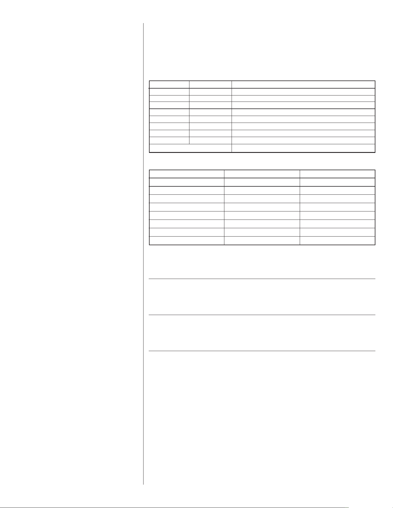
4. Tools Required For Installing & Servicing R-410A Models
Manifold Sets:
-Up to 800 PSIG High side
-Up to 250 PSIG Low Side
-550 PSIG Low Side Retard
Manifold Hoses:
-Service Pressure Rating of 800 PSIG
Recognize this symbol as an indica-
tion of Important Safety Information!
!
!
WARNING
IMPORTANT: ALL MANUFACTUR-
ER PRODUCTS MEET CURRENT
FEDERAL OSHA GUIDELINES FOR
SAFETY. CALIFORNIA
PROPOSITION 65 WARNINGS ARE
REQUIRED FOR CERTAIN PROD-
UCTS, WHICH ARE NOT COVERED
BY THE OSHA STANDARDS.
CALIFORNIA'S PROPOSITION 65
REQUIRES WARNINGS FOR PROD-
UCTS SOLD IN CALIFORNIA THAT
CONTAIN, OR PRODUCE, ANY OF
OVER 600 LISTED CHEMICALS
KNOWN TO THE STATE OF
CALIFORNIA TO CAUSE CANCER
OR BIRTH DEFECTS SUCH AS
FIBERGLASS INSULATION, LEAD
IN BRASS, AND COMBUSTION
PRODUCTS FROM NATURAL GAS.
ALL “NEW EQUIPMENT” SHIPPED
FOR SALE IN CALIFORNIA WILL
HAVE LABELS STATING THAT THE
PRODUCT CONTAINS AND/OR
PRODUCES PROPOSITION 65
CHEMICALS. ALTHOUGH WE HAVE
NOT CHANGED OUR PROCESSES,
HAVING THE SAME LABEL ON ALL
OUR PRODUCTS FACILITATES
MANUFACTURING AND SHIPPING.
WE CANNOT ALWAYS KNOW
“WHEN, OR IF” PRODUCTS WILL
BE SOLD IN THE CALIFORNIA
MARKET.
YOU MAY RECEIVE INQUIRIES
FROM CUSTOMERS ABOUT CHEMI-
CALS FOUND IN, OR PRODUCED
BY, SOME OF OUR HEATING AND
AIR-CONDITIONING EQUIPMENT,
OR FOUND IN NATURAL GAS USED
WITH SOME OF OUR PRODUCTS.
LISTED BELOW ARE THOSE CHEM-
ICALS AND SUBSTANCES COM-
MONLY ASSOCIATED WITH SIMI-
LAR EQUIPMENT IN OUR INDUS-
TRY AND OTHER MANUFACTUR-
ERS.
• GLASS WOOL (FIBERGLASS)
INSULATION
• CARBON MONOXIDE (CO)
• FORMALDEHYDE
• BENZENE
MORE DETAILS ARE AVAILABLE
AT THE WEBSITES FOR OSHA
(OCCUPATIONAL SAFETY AND
HEALTH ADMINISTRATION), AT
WWW.OSHA.GOV
AND THE STATE
OF CALIFORNIA'S OEHHA (OFFICE
OF ENVIRONMENTAL HEALTH
HAZARD ASSESSMENT), AT
WWW.OEHHA.ORG. CONSUMER
EDUCATION IS IMPORTANT SINCE
THE CHEMICALS AND SUB-
STANCES ON THE LIST ARE
FOUND IN OUR DAILY LIVES. MOST
CONSUMERS ARE AWARE THAT
PRODUCTS PRESENT SAFETY AND
HEALTH RISKS, WHEN IMPROPER-
LY USED, HANDLED AND MAIN-
TAINED.
6
Recovery Cylinders:
-400 PSIG Pressure Rating
-Dept. of Transportation 4BA400 or BW400
IV. CHECKING PRODUCT RECEIVED
Upon receiving the unit, inspect it for any damage from shipment. Claims for damage,
either shipping or concealed, should be filed immediately with the shipping company.
Check the unit model number, heating size, electrical characteristics, and accessories to
determine if they are correct.
V. EQUIPMENT PROTECTION FROM THE
V. ENVIRONMENT
The metal parts of this unit may be subject to rust or deterioration in adverse environ-
mental conditions. This oxidation could shorten the equipment’s useful life. Salt spray,
fog or mist in seacoast areas, sulphur or chlorine from lawn watering systems, and vari-
ous chemical contaminants from industries such as paper mills and petroleum refineries
are especially corrosive.
If the unit is to be installed in an area where contaminants are likely to be a prob-
lem, special attention should be given to the equipment location and exposure.
1. Avoid having lawn sprinkler heads spray direction on the unit cabinet.
2. In coastal areas, locate the unit on the side of the building away from the waterfront.
3. Shielding provided by a fence or shrubs may give some protection.
Regular maintenance will reduce the buildup of contaminents and help to protect
the unit’s finish.
1. Frequent washing of the cabinet, fan blade and coil with fresh water will remove
most of the salt or other contaminants that build up on the unit.
2. Regular cleaning and waxing of the cabinet with a good automobile polish will pro-
vide some protection.
3. A good liquid cleaner may be used several times a year to remove matter that will
not wash off with water.
Several different types of protective coatings are offered in some areas. These coatings
may provide some benefit, but the effectiveness of such coating materials cannot be ver-
ified by the equipment manufacturer.
The best protection is frequent cleaning, maintenance and minimal exposure to
contaminants.
VI. INSTALLATION
A. GENERAL
1. PRE-INSTALLATION CHECK-POINTS
Before attempting any installation, the following points should be carefully consid-
ered:
a. Structural strength of supporting members.
(rooftop installation)
b. Clearances and provision for servicing.
c. Power supply and wiring.
d. Air duct connections.
!
CAUTION
R-410A systems operate at higher pressures than R-22 systems. Do not use
R-22 service equipment or components on R-410A equipment.
!
WARNING
DISCONNECT ALL POWER TO THE UNIT BEFORE STARTING MAINTENANCE.
FAILURE TO DO SO CAN RESULT IN SEVERE ELECTRICAL SHOCK OR
DEATH.
7
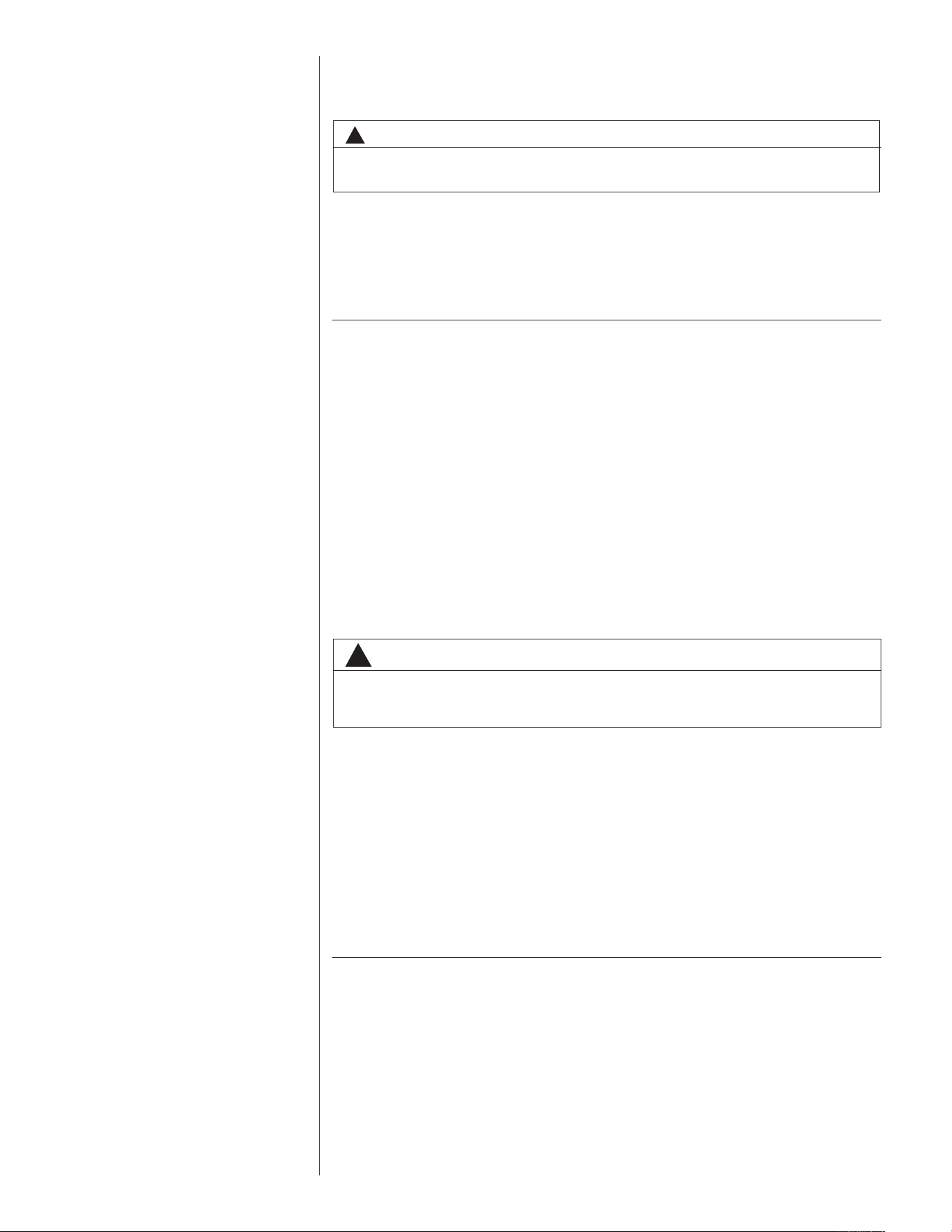
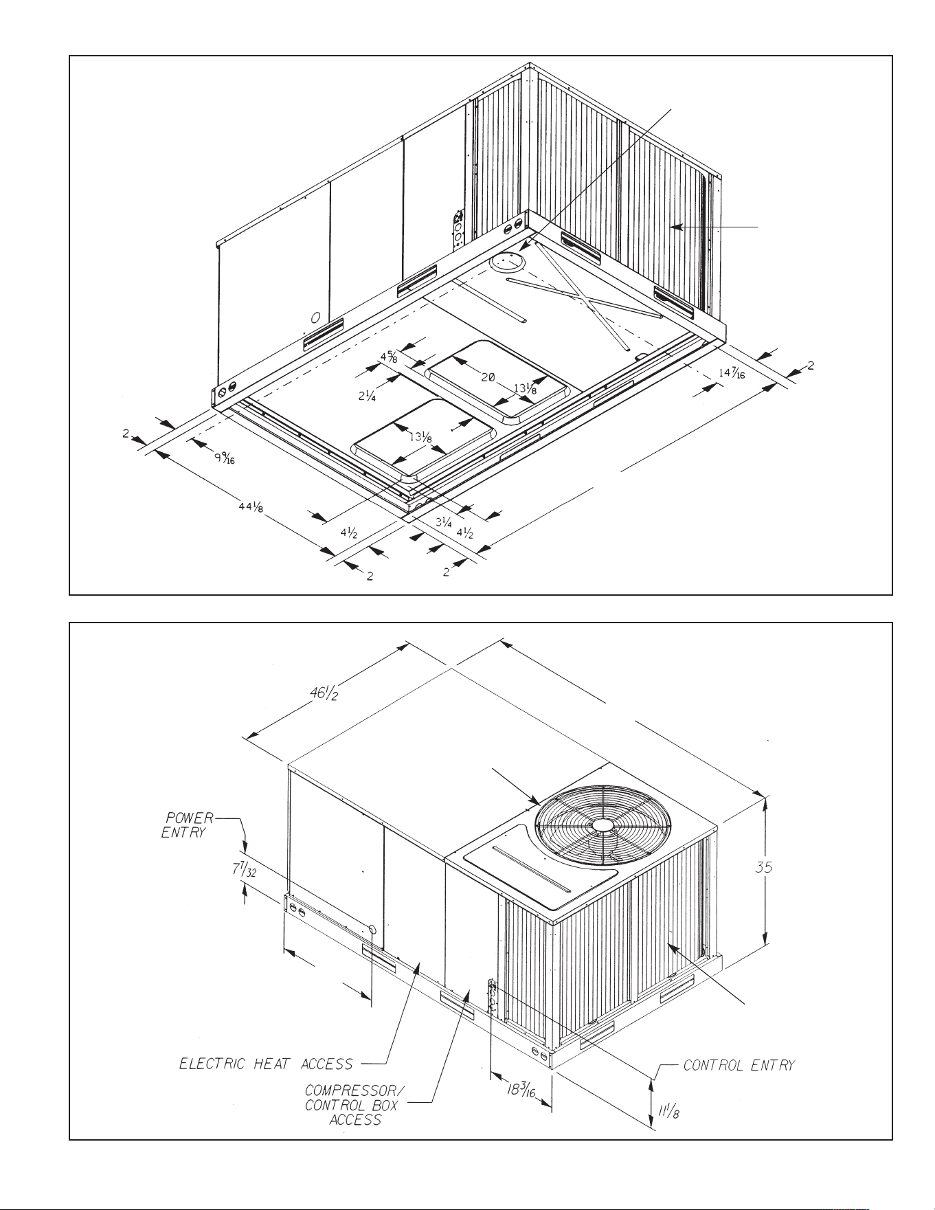
FIGURE 1
U
NIT DIMENSIONS
RJNL/RJPL 3-5 TON
FIGURE 2
UNIT DIMENSIONS
RJNL/RJPL 3-5 TON
ILL I316
ILL I305
35
8
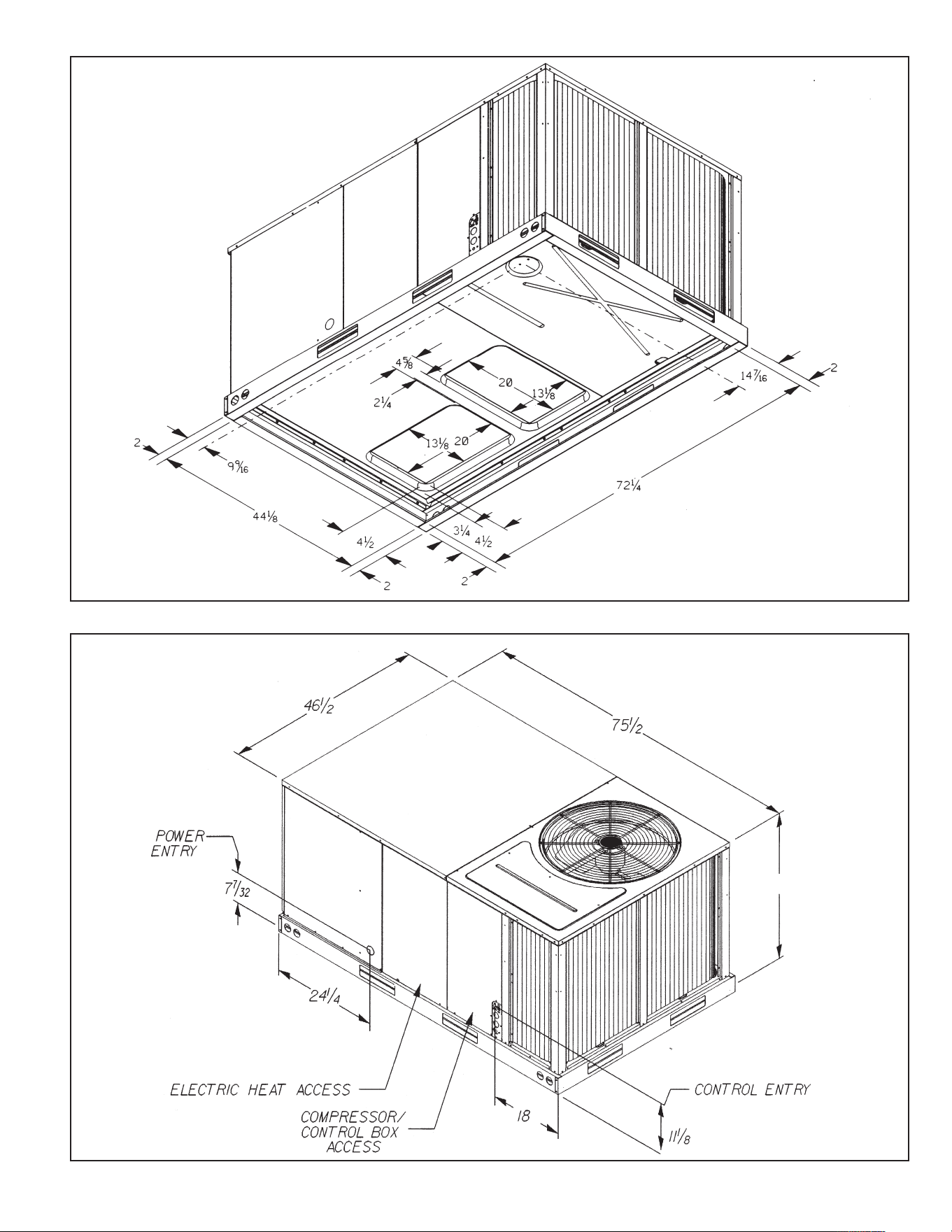
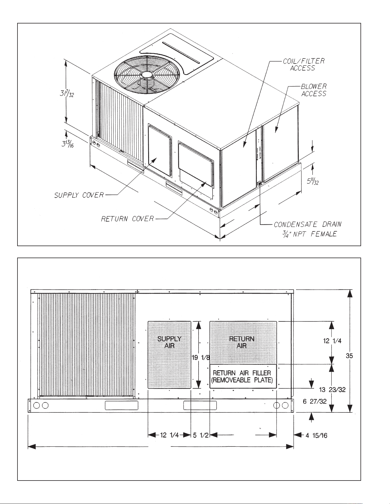
FIGURE 3
U
NIT DIMENSIONS
RJNL/RJPL 3-5 TON
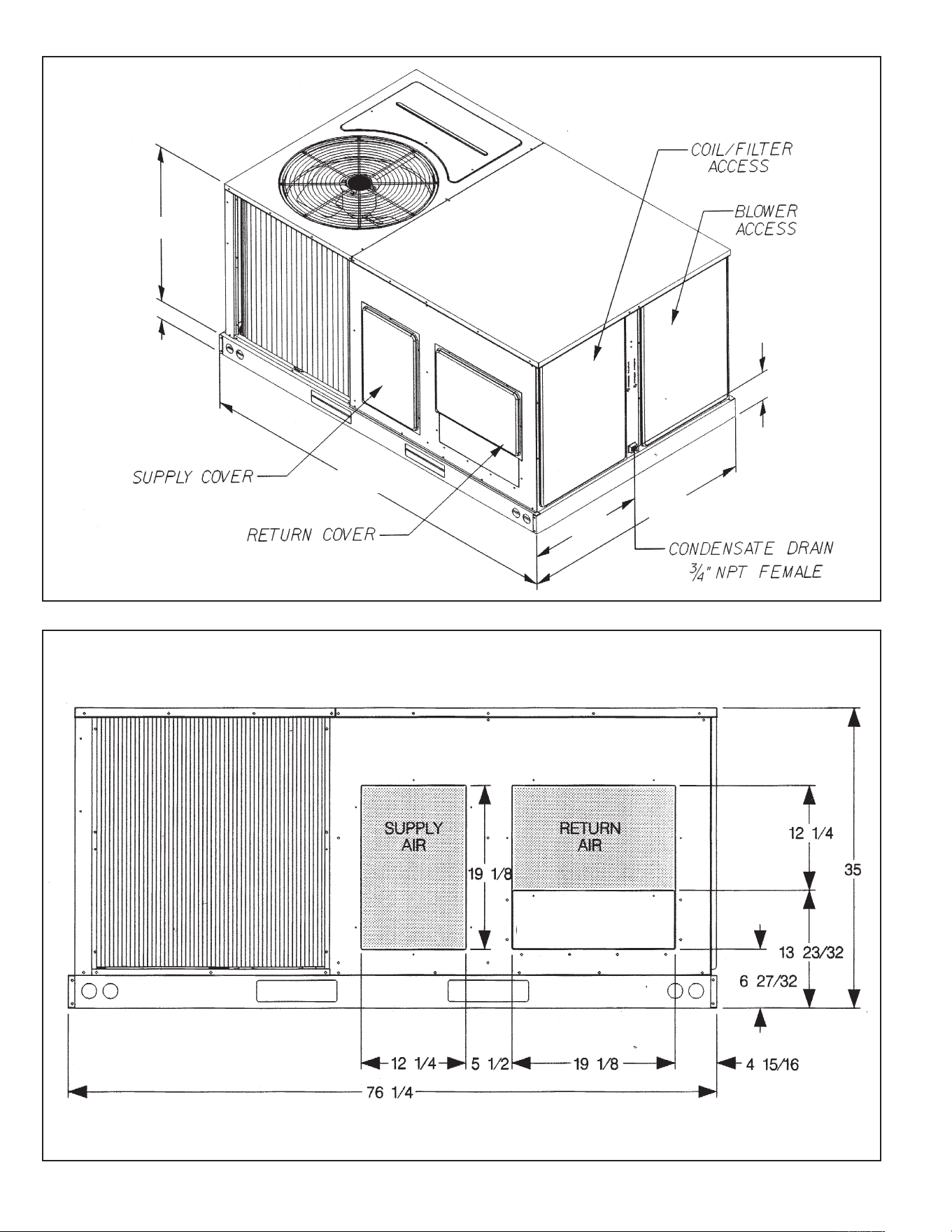
FIGURE 4
UNIT DIMENSIONS
RJNL/RJPL 3 TO 5 TON
I
LL I304
ILL I288
RETURN AIR FILTER
(REMOVABLE PLATE)
76
1
⁄4
3
1
3
⁄16
31
7
⁄3
2
48
3
⁄32
5
11
⁄32
24
9
FIGURE 5
U
NIT DIMENSIONS
BOTTOM VIEW
RJNL 6 TON
FIGURE 6
UNIT DIMENSIONS
RJNL 6 TON
I
LL 1316
ILL1305
26
7
8
1
⁄4
81
17
⁄3
2
26
1
⁄4
30
1
⁄4
BASE ELECTRICAL
ENTRY
CONDENSER
COIL
CONDENSER COIL
CONDENSER FAN
DISCHARGE GRILLE
10
FIGURE 7
U
NIT DIMENSIONS
R
JNL 6 TON
FIGURE 8
UNIT DIMENSIONS
RJNL 6 TON
I
LL 1304
ILL 1288
82
1
⁄4
82 1/4
25 1/8
24
1
⁄32
48
1
⁄16
11
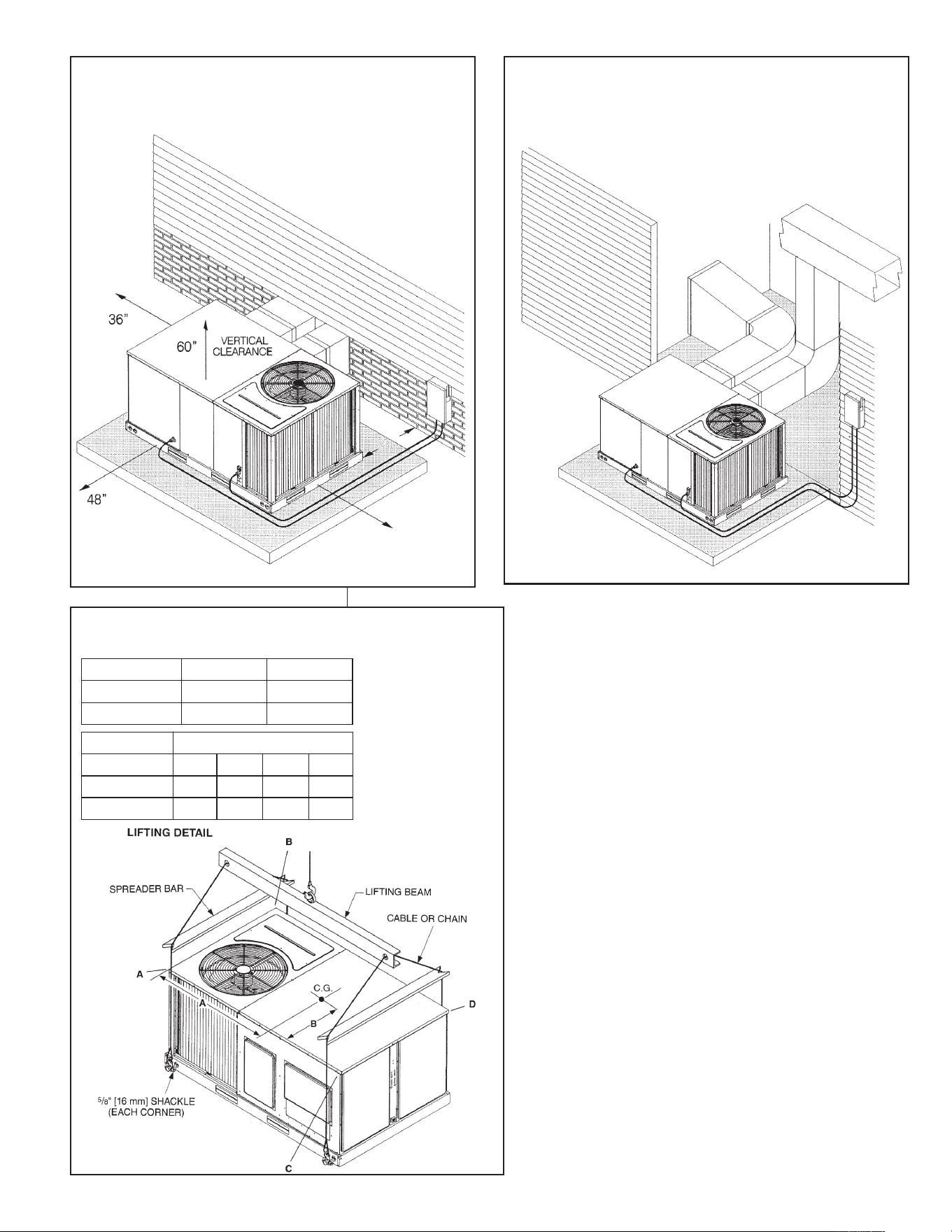
FIGURE 9
PACKAGED HEAT PUMP
O
UTSIDE SLAB INSTALLATION, BASEMENT OR
CRAWL SPACE DISTRIBUTION SYSTEM
ILL I308
FIGURE 10
P
ACKAGED HEAT PUMP
OUTSIDE SLAB INSTALLATION, CLOSET DISTRIBUTION
S
YSTEM. SLAB FLOOR CONSTRUCTION
I
LL I309
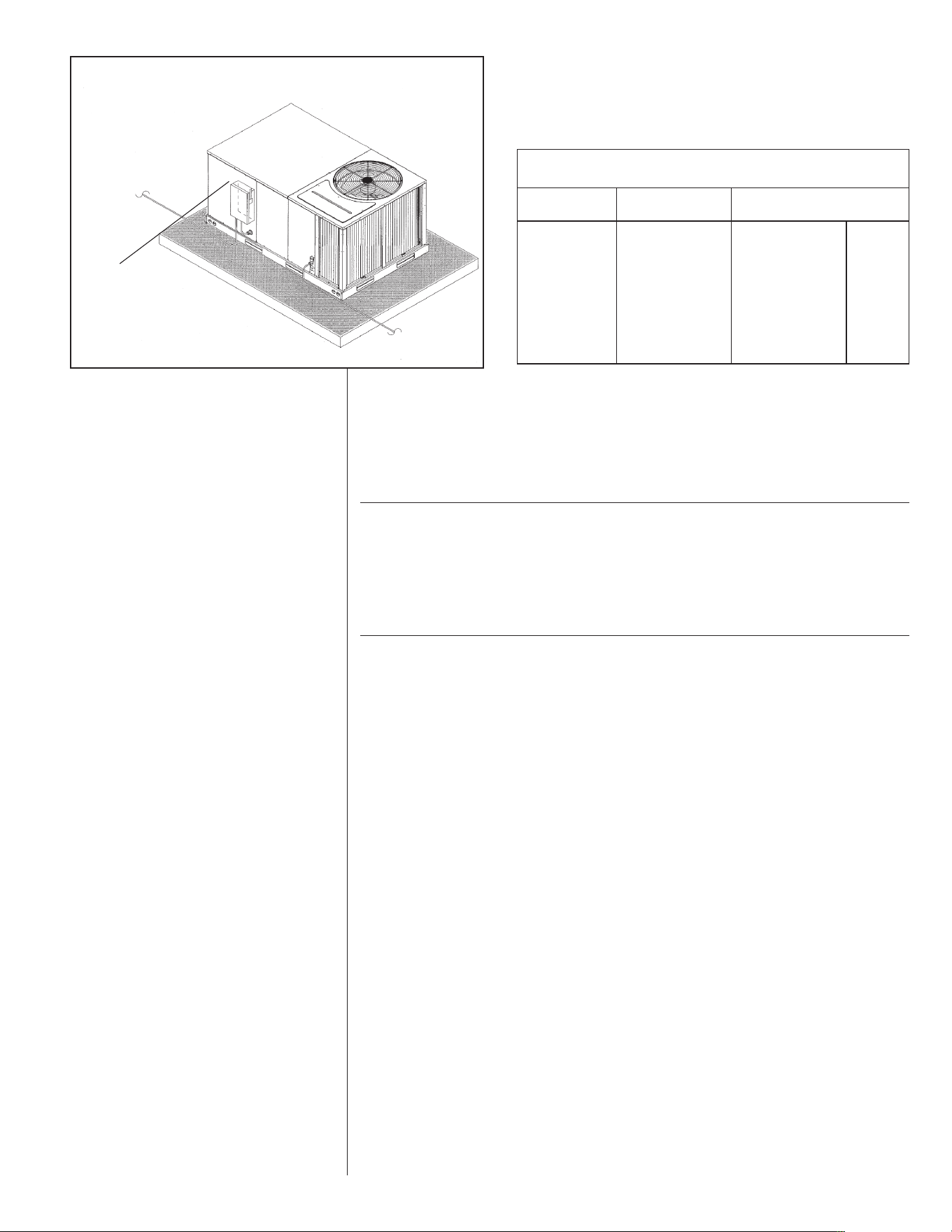
FIGURE 11
PACKAGED HEAT PUMP
RIGGING FOR LIFTING
18”
12”
*Allow 57" for economizer
on duct side.
*
Capacity Tons [kW] A in. [mm] B in. [mm]
3.5 [10.6-17.6]
38
1
⁄4 [972] 25
3
⁄4 [654]
6 [21.1]
39 [991]
26
1
⁄8 [664]
Capacity Tons [kW] Corner Weights by Percentage
ABCD
23% 28%27%
3.5 [10.6-17.6]
6 [21.1]
22%
23%
29% 21% 27%
12
e. Drain facilities and connections.
f. Location for minimum noise.
2. LOCATION
These units are designed for outdoor installations. They can be mounted on a
slab or rooftop. They are not to be installed within any part of a structure such as
an attic, crawl space, closet, or any other place where condenser air flow is
restricted or other than outdoor ambient conditions prevail. Since the application
of the units is of the outdoor type, it is important to consult your local code authori-
ties at the time the first installation is made.
B. OUTSIDE SLAB INSTALLATION
(Typical outdoor slab installations are shown in Figures 9 and 10.)
1. Select a location where external water drainage cannot collect around the unit.
2. Provide a level concrete slab extending 3" beyond all four sides of the unit. The
slab should be sufficient above grade to prevent ground water from entering the
unit. IMPORTANT: To prevent transmission of noise or vibration, slab should not
be connected to building structure.
3. The location of the unit should be such as to provide proper access for inspection
and servicing.
4. Locate unit where operating sounds will not disturb owner or neighbors.
5. Locate unit so roof runoff water does not pour directly on the unit. Provide gutter
or other shielding at roof level. Do not locate unit in an area where excessive
snow drifting may occur or accumulate.
6. It is essential that the unit be elevated above the base pad to allow for conden-
sate drainage and possible refreezing of condensation. Provide a base pad which
is slightly pitched away from the structure. Route condensate off base pad to an
area which will not become slippery and result in personal injury.
7. Where snowfall is anticipated, the height of the unit above the ground level must
be considered. Mount unit high enough to be above average area snowfall and to
allow for proper condensate drainage.
I
LL I301
ILL I300
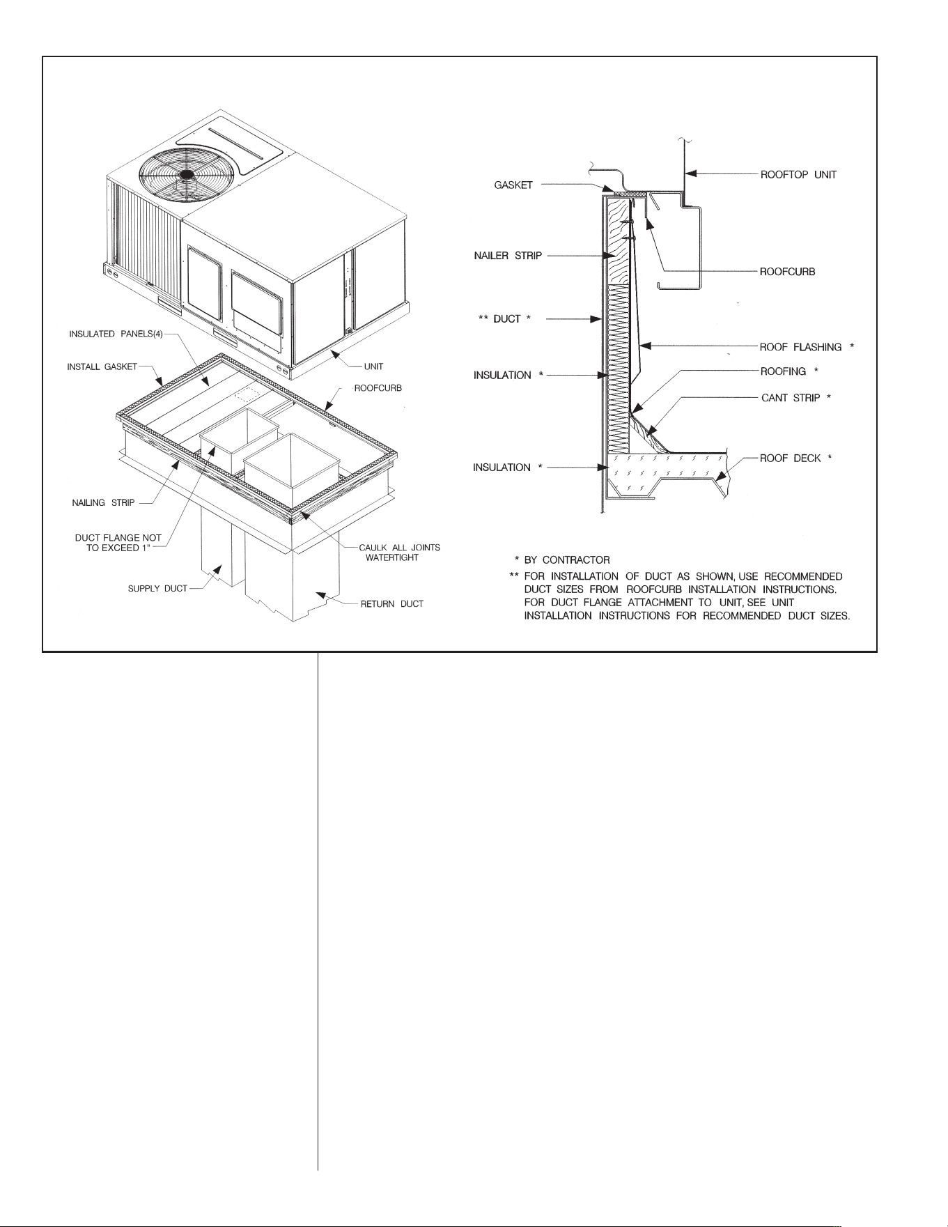
FIGURE 12
P
ACKAGED HEAT PUMP
ROOFCURB INSTALLATION
13
C. CLEARANCES
The following minimum clearances must be observed for proper unit performance
and serviceability.
1. Provide 48" minimum clearance at the front of the unit. Provide 36" minimum
clearance at the left and right side of the unit for service access.
2. Provide 60" minimum clearance between top of unit and maximum 3 foot over-
hang.
3. Unit is design certified for application on combustible flooring with 0" minimum
clearance.
4. See Figure 9 for illustration of minimum installation-service clearances.
D. ROOFTOP INSTALLATION
1. Before locating the unit on the roof, make sure that the strength of the roof and
beams is adequate at that point to support the weight involved. (See specification
sheet for weight of unit.) This is very important and user’s responsibility.
2. For rigging and roofcurb details, see Figures 11 and 12. Use field-furnished
spreaders.
3. For roofcurb assembly, see Roofcurb Installation Instructions.
4. If the roofcurb is not used, provisions for disposing of condensate water runoff
during defrosting must be provided.
5. The unit should be placed on a solid and level roofcurb or platform of adequate
strength. See Figure 13.
6. The location of the unit on the roof should be such as to provide proper access for
inspection and servicing.
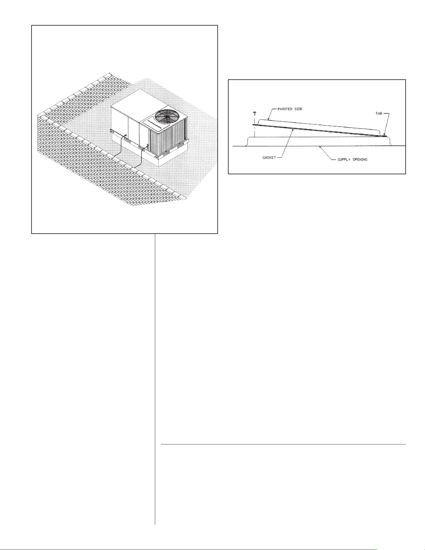
IMPORTANT: If unit will not be put into service immediately, cover supply and return
openings to prevent excessive condensation.
VII. DUCTWORK
Ductwork should be fabricated by the installing contractor in accordance with local codes
and NFPA90A. Industry manuals may be used as a guide when sizing and designing the
duct system - contact Air Conditioning Contractors of America, 1513 16th St. N.W.,
Washington, D.C. 20036.
I
LL I310
FIGURE 13
PACKAGED HEAT PUMP
F
LAT ROOFTOP INSTALLATION, ATTIC OR DROP CEILING
DISTRIBUTION SYSTEM. MOUNTED ON
R
OOFCURB. CURB MUST BE LEVEL
FIGURE 14
COVER GASKET DETAIL
ILL I631
The unit should be placed as close to the space to be air conditioned as possible allow-
ing clearance dimensions as indicated. Ducts should be run as directly as possible to
supply and return outlets. Use of non-flammable waterproof flexible connectors on both
supply and return connections at the unit to reduce noise transmission is recommended.
It is preferable to install the unit on the roof of the structure if the registers or diffusers
are located on the wall or in the ceiling. A slab installation could be considered when the
registers are low on a wall or in the floor.
On ductwork exposed to outside air conditions of temperature and humidity, use a mini-
mum of 2" of insulation and a vapor barrier. Distribution system in attic, furred space or
crawl space should be insulated with at least 2" of insulation with vapor barrier. One-half
to 1" thickness of insulation is usually sufficient for ductwork inside the air conditioned
space.
Balancing dampers should be provided for each branch duct in the supply system.
Ductwork should be properly supported from the structure.
When installing ductwork, consider the following items:
1. Noncombustible flexible connectors should be used between ductwork and unit to
reduce noise and vibration transmission into the ductwork.
2. When auxiliary heaters are installed, use noncombustible flexible connectors and
clearance to combustible material of 0" for the first 3 feet of discharge duct.
Clearance to unit top and side is 0".
VIII.FILTERS
This unit is provided with 2 - 25" x 16" x 1" (3-5 ton) 4 - 16" x 16" x 1" (6 ton) disposable
filters. When replacing filters, ensure they are inserted fully to the back to prevent
bypass.
IX. CONVERSION PROCEDURE
DOWNFLOW TO HORIZONTAL
1. Remove the screws and covers from the outside of the supply and return sections.
2. Install the covers in the bottom supply and return openings with the painted side up.
See Figure 15. Use the existing gasket to seal the covers.
3. Secure the supply cover to the base of the unit with 1 screw, engaging prepunched
tab in unit base.
4. Secure the return cover to the base of the unit with screws, engaging prepunched
holes in the unit base.
14
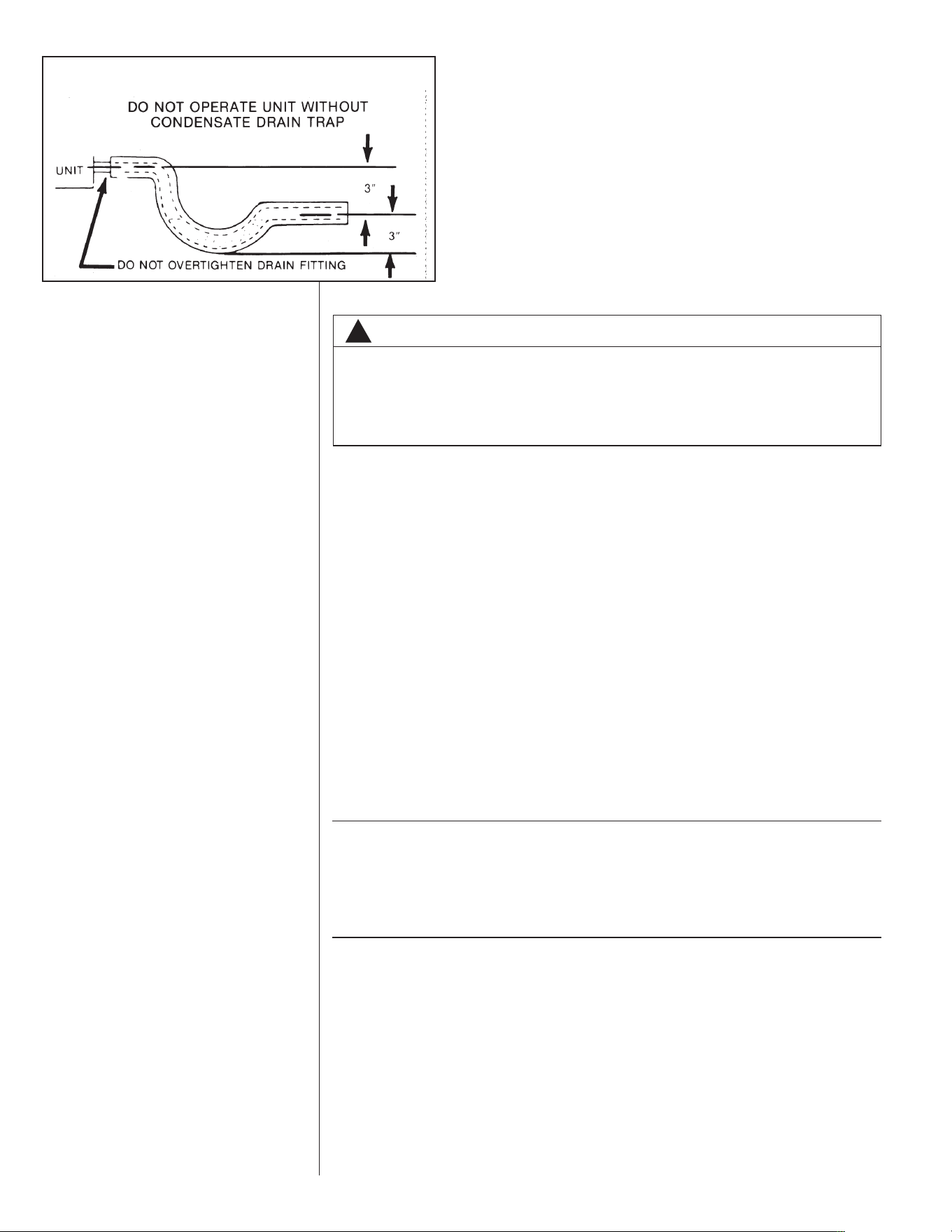
FIGURE 15
C
ONDENSATE DRAIN
!
WARNING
DO NOT, UNDER ANY CIRCUMSTANCES, CONNECT RETURN DUCTWORK TO
ANY OTHER HEAT PRODUCING DEVICE SUCH AS A FIREPLACE INSERT,
STOVE, ETC. UNAUTHORIZED USE OF SUCH DEVICES MAY RESULT IN FIRE,
CARBON MONOXIDE POISONING, EXPLOSION, PROPERTY DAMAGE,
SEVERE PERSONAL INJURY OR DEATH.
15
X. CONDENSATE DRAIN
The condensate drain connection of the evaporator is 3/4" nominal female pipe thread.
IMPORTANT: Install a condensate trap to ensure proper condensate drainage. See
Figure 15.
XI. CONDENSATE DRAIN, OUTDOOR COIL
The outdoor coil during heating operation will sweat or run water off. The outdoor coil will
also run water off during the defrost cycle. See Section V, Installation, for mounting pre-
cautions.
XII. ELECTRICAL WIRING
Field wiring must comply with the National Electrical Code* and local ordinances that may
apply.
*C.E.C. in Canada
A. POWER WIRING
1. It is important that proper electrical power is available at the unit. Voltage should not
vary more than 10% from that stamped on the unit rating plate. On three phase
units, phases must be balanced within 3%.
➤ 2. Install a branch circuit disconnect within sight of the unit and of adequate size to
handle the starting current. Refer to Figure 16 for proper location.
3. For branch circuit wiring (main power supply to unit disconnect), the minimum wire
size can be determined from Table C using the circuit ampacity found on the unit
nameplate or from the Electrical Data.
4. This unit incorporates single point electrical connection for unit and electric heat
accessory.
5. Power wiring must be run in grounded rain-tight conduit. Connect the power field
wiring as follows:
a. NO ELECTRIC HEAT - Connect the field wires directly to the contactor pigtails in
the electric heat access area. Connect ground wire to ground lug.
b. WITH ELECTRIC HEAT - Connect the field wires to the terminal block on the
electric heater kit in the electric heat access area. Connect the ground wire to the
ground lug on the heater kit.
NOTE: For field installation of a heater kit, follow the instructions provided with the heater
kit.
TABLE A
W
IRE SIZES
AWG Copper AWG Aluminum Connector Type and Size
Wire Size Wire Size (or equivalent)
#12 #10 T&B Wire Nut PT2
#10 #8 T&B Wire Nut PT3
#8 #6 Ilsco Split Bolt AK-6
#6 #4 Ilsco Split Bolt AK-4
#4 #2 Ilsco Split Bolt AK-2
#3 #1 Ilsco Split Bolt AK-1/0
#2 #0 Ilsco Split Bolt AK-1/0
#1 #00 Ilsco Split Bolt AK-2/0
#0 #000 Ilsco Split Bolt AK-4/0
FIGURE 16
B
RANCH CIRCUIT DISCONNECT LOCATION
TO POWER
B
RANCH CIRCUIT
D
ISCONNECT
T
O CONTROL
16
6. The pigtail wires in the electric heat access area are factory wired to the contactor in
the control box.
7. DO NOT connect aluminum field wires to electric heat kit power input terminals.
B. SPECIAL INSTRUCTIONS FOR POWER WIRING WITH ALUMINUM
CONDUCTORS.
1. Select the equivalent aluminum wire size from the tabulation below:
2. Attach a length (6" or more) of recommended size copper wire to the unit terminals
L1 and L3 for single phase, L1, L2, L3 for three phase.
3. Splice copper wire pigtails to aluminum wire with U.L. recognized connectors for
copper-aluminum splices. Follow these instructions very carefully to make a positive
and lasting connection;
a. Strip insulation from aluminum conductor.
b. Coat the stripped end of the aluminum wire with the recommended inhibitor and
wire brush aluminum surface through inhibitor. Inhibitors: Brundy, Pentex “A”;
Alcoa, No. 2EJC; T&B KPOR Shield.
ILL I312
F
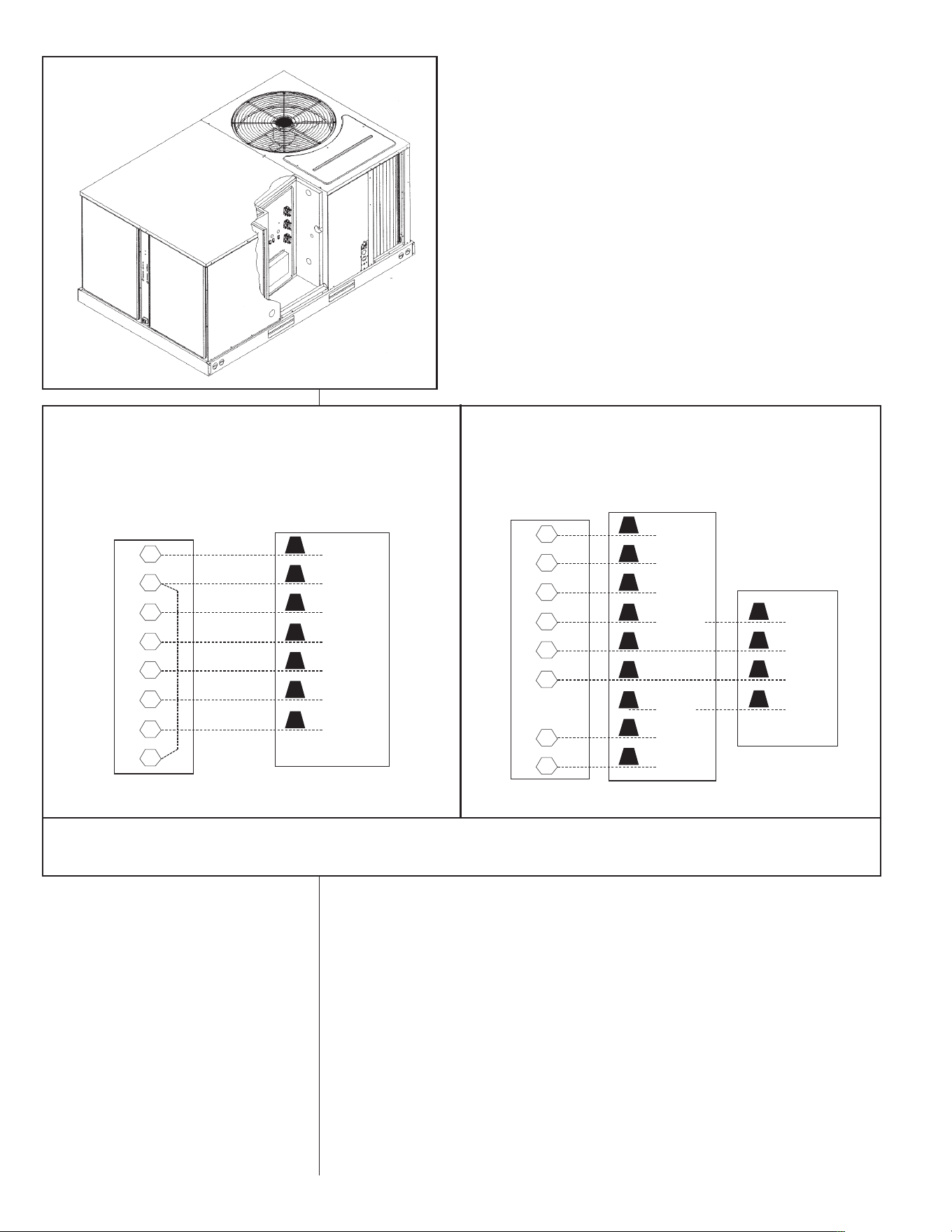
IGURE 17
H
EATER KIT INSTALLATION
R
W2
X
B
Y1
Y2
G
E
RED
BLACK
BROWN
BLUE
YELLOW
ORANGE
GRAY
NOTES: IF EMERGENCY HEAT RELAY AND OUTDOOR THERMOSTATS ARE NOT USED, A JUMPER BETWEEN “W2” AND “E” CAN BE INSTALLED TO TRANSFER
CONTROL OF HEATING TO THE FIRST STAGE WHEN THE SYSTEM SWITCH IS IN THE EMERGENCY HEAT POSITION.
Y2 IS ONLY USED WITH OPTIONAL ECONOMIZER.
THERMOSTAT
SUB-BASE
UNIT CONTROL
WIRE PIGTAILS
STANDARD
R
G
B
X
E
W2
Y1
Y2
RED
GRAY
BLUE
BROWN BROWN
RED
WHITE
BLACK BLACK
YELLOW
ORANGE
THERMOSTAT
SUB-BASE
UNIT CONTROL
WIRE PIGTAILS
OUTDOOR
THERMOSTAT
W/EMERGENCY
HEAT RELAY
WITH ONE OUTDOOR THERMOSTAT
W/EMERGENCY HEAT RELAY
FIGURE 18
V
OLTAGE CONNECTIONS DIAGRAMS
TABLE C
C
OPPER WIRE SIZE – AWG (1% VOLTAGE DROP)
17
300
250
200
150
100
50
Supply
Wire
Length
Feet
Circuit Ampacity
NOTE:
1. Wire size based on 60ºC type copper conductors below 100 ampacity. 2. Wire size based on 75ºC type copper conductors for 100 ampacity and above.
4
4
6
8
10
14
15
3
4
4
6
8
12
20
2
3
4
6
8
10
25
2
3
4
4
6
10
30
1
2
3
4
6
8
35
1/0
1
2
4
6
8
40
1/0
1
2
3
4
6
45
2/0
1/0
1
3
4
6
50
2/0
1/0
1
2
4
6
55
3/0
2/0
1/0
2
3
4
60
3/0
2/0
1/0
1
3
4
65
3/0
2/0
1/0
1
2
4
70
4/0
3/0
2/0
1/0
2
3
75
4/0
3/0
2/0
1/0
2
3
80
4/0
3/0
2/0
1/0
1
3
85
4/0
4/0
3/0
1/0
1
2
90
250
4/0
3/0
2/0
1
2
95
250
4/0
3/0
2/0
1
2
100
250
4/0
3/0
2/0
1
2
105
250
4/0
3/0
2/0
1/0
2
110
300
250
4/0
2/0
1/0
1
115
300
250
4/0
3/0
1/0
1
120
300
250
4/0
3/0
1/0
1
125
300
250
4/0
3/0
1/0
1
130
300
250
4/0
3/0
1/0
1/0
135
350
350
300
4/0
1/0
1/0
140
350
350
300
4/0
2/0
1/0
145
350
350
300
4/0
2/0
1/0
150
350
350
300
4/0
2/0
2/0
155
c. Clean and recoat aluminum conductor with inhibitor.
d
. Make the splice using the above listed wire nuts or split bolt connectors.
e. Coat the entire connection with inhibitor and wrap with electrical insulating tape.
WARRANTY MAY NOT APPLY IF CONNECTIONS ARE NOT MADE PER INSTRUC-
TIONS
C. CONTROL WIRING (Class II)
1. Low voltage wiring should not be run in conduit with power wiring.
2. Control wiring is routed through the 7/8" hole adjacent to the compressor access
panel. See Figure 2. Use a minimum #18 AWG thermostat wire. For wire lengths
exceeding 50', use #16 AWG thermostat wire. The low voltage wires are connected
to the unit pigtails which are supplied with the unit below the unit control box.
3. It is necessary that only heat pump thermostats be used.
4. Figure 18 shows representative low voltage connection diagrams. Read your ther-
mostat installation instructions for any special requirements for your specific thermo-
stat.
NOTE — Units installed in Canada require that an outdoor thermostat (30,000 min.
cycles of endurance) be installed and be wired with C.E.C. Class I wiring.
D. INTERNAL WIRING
1. A diagram of the internal wiring of this unit is located on the inside of the compres-
sor access panel. If any of the original wire as supplied with the appliance must be
replaced, the wire gauge and insulation must be the same as original wiring.
IMPORTANT: Some single phase units are equipped with a single pole contactor.
Caution must be exercised when servicing as only one leg of the power supply is bro-
ken with the contactor. Some models are equipped with electrically commutated blow-
er motors which are constantly energized unless the main unit disconnect is in the off
position.
E. GROUNDING
F. THERMOSTAT
The thermostat should be mounted on an inside wall about five feet above the floor in
a location where it will not be affected by unconditioned air, sun, or drafts from open
doors or other sources. READ installation instructions in heat pump thermostat pack-
age CAREFULLY because each has some different wiring requirements.
XIII. INDOOR AIR FLOW DATA
Direct-drive blower models are shipped factory wired for the proper speed at a typical
external static. Belt-drive blower models have motor sheaves set for proper CFM at a
typical external static.
!
WARNING
THE UNIT MUST BE PERMANENTLY GROUNDED. A GROUNDING LUG IS PRO-
VIDED IN THE ELECTRIC HEAT ACCESS AREA FOR A GROUND WIRE. FAILURE
TO GROUND THIS UNIT CAN RESULT IN FIRE OR ELECTRICAL SHOCK CAUS-
ING PROPERTY DAMAGE, SEVERE PERSONAL INJURY OR DEATH.

18
XIV. CRANKCASE HEAT (OPTIONAL)
C
rankcase heat is not required on scroll type compressors, but may be necessary for
difficult starting situations.
XV. PRE-START CHECK
1. Is unit properly located and slightly slanted toward indoor condensate drain?
2. Is ductwork insulated, weatherproofed, with proper spacing to combustible materi-
a
ls?
3. Is air free to travel to and from outdoor coil? (See Figure 9.)
4. Is the wiring correct, tight, and according to unit wiring diagram?
5. Is unit grounded?
6. Are field supplied air filters in place and clean?
7. Do the outdoor fan and indoor blower turn freely without rubbing, and are they tight
on the motor shafts?
8. Is unit elevated to allow for outdoor coil condensate drainage during heating opera-
tion and defrost?
XVI. STARTUP
1. Turn thermostat to “OFF,” turn “on” power supply at disconnect switch.
2. Turn temperature setting as high as it will go.
3. Turn fan switch to “ON.”
4. Indoor blower should run. Be sure it is running in the right direction.
5. Turn fan switch to “AUTO.” Turn system switch to “COOL” and turn temperature set-
ting below room temperature. Unit should run in cooling mode.
6. Is outdoor fan operating correctly in the right direction?
7. Is compressor running correctly.
8. Turn thermostat system switch to “HEAT.” Unit should stop. Wait 5 minutes, then
raise temperature setting to above room temperature. Unit should run in heating
mode and after about 30 to 50 seconds auxiliary heaters, if installed, should come
on.
9. Check the refrigerant charge using the instructions located on compressor access
panel cover. Replace service port caps. Service port cores are for system access
only and will leak if not tightly capped.
10. Turn thermostat system switch to proper mode “HEAT” or “COOL” and set thermo-
stat to proper temperature setting. Record the following after the unit has run some
time.
A. Operating Mode _______________________________
B. Discharge Pressure (High) ___________________PSIG
C. Vapor Pressure at Compressor (Low) __________PSIG
D. Vapor Line Temperature at Compressor __________°F.
E. Indoor Dry Bulb______________________________°F.
F. Indoor Wet Bulb _____________________________°F.
G. Outdoor Dry Bulb ____________________________°F.
H. Outdoor Wet Bulb ____________________________°F.
I. Voltage at Contactor ________________________Volts
J. Current at Contactor _______________________Amps
K. Model Number_________________________________
L. Serial Number _________________________________
M.Location______________________________________
N. Owner _______________________________________
O. Date_________________________________________
11. Adjust discharge air grilles and balance system.
12. Check ducts for condensation and air leaks.
13. Check unit for tubing and sheet metal rattles.
14. Instruct the owner on operation and maintenance.
15. Leave “INSTALLATION” and ”USE AND CARE“ instructions with owner
XVII. OPERATION
Most single phase units are operated PSC (no start relay or start capacitor). It is impor-
tant that such systems be off for a minimum of 5 minutes before restarting to allow
equalization of pressures. The thermostat should not be moved to cycle unit without
waiting five minutes. To do so may cause the compressor to stop on an automatic open
overload device or blow a fuse. Poor electrical service can cause nuisance tripping in
overloads or blow fuses.

19
IMPORTANT: The compressor has an internal overload protector. Under some condi-
tions, it can take up to 2 hours for this overload to reset. Make sure overload has had
time to reset before condemning the compressor.
Some units are equipped with a time delay control (TDC1). The control allows the blower
to operate for up to 90 seconds after the thermostat is satisfied.
XVIII. AUXILIARY HEAT
The amount of auxiliary heat required depends on the heat loss of the structure to be
heated and the capacity of the heat pump. It is good practice to install strip heat to main-
tain at least 60ºF indoor temperatures in case of compressor failure. The auxiliary heat
is energized by the second stage of the thermostat. The amount of electric heat that is
allowed to come on, as determined by the output of the heat pump, may be controlled by
a
n outdoor thermostat.
A. CONTROL SYSTEM OPERATION
1. In the cooling mode, the thermostat will, on a call for cooling, energize the com-
pressor contactor and the indoor blower relay. The indoor blower can be operated
continuously by setting the thermostat fan switch at the “ON” position. The revers-
ing valve coil is de-energized.
2. In the heating mode, the first heat stage of the thermostat will energize the com-
pressor contactor and the indoor blower relay. The second heat stage will turn on
one or more supplementary resistance heaters. The reversing valve is energized
except in defrost. If required or considered desirable, the resistance heat may
also be controlled by outdoor thermostats.
XIX. DEMAND DEFROST CONTROL AND
HIGH/LOW PRESSURE CONTROLS
The demand defrost control monitors the outdoor ambient temperature, outdoor coil
temperature and the compressor run time to determine when a defrost cycle is
required.
Enhanced Feature Demand Defrost Control: This defrost control has high and
low pressure control inputs with unique pressure switch logic built into the micro-
processor to provide compressor and system protection without nuisance lockouts.
The control cycles the compressor off for 30 seconds at the beginning and the end
of the defrost cycle to eliminate the increased compressor noise caused by rapidly
changing system pressures when the reversing valve switches. See next page for
diagnostic flash codes and sensor resistance values at various temperatures.
DEFROST INITIATION
A defrost will be initiated when the three conditions below are satisfied:
1. The outdoor coil temperature is below 35°F as measured by a good coil sensor,
2. The compressor has operated for at least 34 minutes with the outdoor coil tem-
perature below 35°F and
3. The measured difference between the ambient temperature and the outdoor
coil temperature is greater than the calculated difference determined by the
defrost control microprocessor.
DEFROST TERMINATION
Once a defrost is initiated, the defrost will continue until fourteen minutes has
elapsed or the coil temperature has reached the selected termination temperature.
The factory setting is 70°F but can be changed to 50°F, 60°F, or 80°F by relocating
the jumper on the control board.
!
WARNING
ONLY ELECTRIC HEATER KITS SUPPLIED BY THIS MANUFACTURER AS
DESCRIBED IN THIS PUBLICATION HAVE BEEN DESIGNED, TESTED, AND
EVALUATED BY A NATIONALLY RECOGNIZED SAFETY TESTING AGENCY
FOR USE WITH THIS UNIT. USE OF ANY OTHER MANUFACTURED ELECTRIC
HEATERS INSTALLED WITHIN THIS UNIT MAY CAUSE HAZARDOUS CONDI-
TIONS RESULTING IN PROPERTY DAMAGE, FIRE, BODILY INJURY OR
DEATH.

20
TEMPERATURE SENSORS
The coil sensor is located on the outdoor coil near the point fed by the distribution
tubes from the expansion device, on the top most cross-over tube. The ambient air
sensor is located outside the control box so it can sense outdoor temperatures.
If the ambient sensor fails, the defrost control will initiate a defrost every 34 minutes
of compressor run time with the coil temperature below 35°F.
If the coil sensor fails, the defrost control will not initiate a defrost.
TEST MODE
The test mode is initiated by shorting the TEST pins. The unit must have an active
heat pump heating call to enter the test mode. In this mode of operation, the enable
temperature is ignored and all timers are sped up. To initiate a manual defrost,
short and hold the TEST pins. Remove the short when the system switches to
defrost mode after the compressor noise abatement delay. The defrost will termi-
nate on time (14 minutes) or when the termination temperature has been reached.
Test Sequence of Operation:
1) Provide a heating call to the heat pump.
2) Short test pins to bypass anti-short cycle timer. (If unit is running, this step is not
necessary.)
3) Short test pins and hold them shorted to enter defrost mode.
4) Release test pins once control exits noise abatement delay.
5) Monitor coil temperature when control exits defrost.
6) Unit should return to heating mode.
TROUBLE SHOOTING DEMAND DEFROST
During the test mode the coil temperature should be monitored. If the system exits
defrost at approximately the termination temperature, the control is operating norml-
ly. If not, check the coil and ambient temperature sensor resistances, using the sen-
sor temperature vs. resistance table at the end of this section.
Immerse the sensor in water and measure the resistance of the sensor. At 35°F the
resistance of the sensor should be approximately 30,000 ohms.
Ensure that the coil sensor is properly installed that is not loose or touching the cab-
inet.
HIGH/LOW PRESSURE CONTROL MONITORING - ENHANCED
DEFROST CONTROL
Status of high and low pressure controls is monitored by the enhanced feature
demand defrost control and the following actions are taken.
High Pressure Control – Provides active protection in both cooling and heating
modes at all outdoor ambient temperatures. The high pressure control is an auto-
matic reset type and opens at approximately 610 psig and closes at approximately
420 psig. The compressor and fan motor will stop when the high pressure control
opens and will start again if the high side pressure drops to approximately 420 psig
where the automatic reset high pressure control resets. If the high pressure control
opens 3 times within a particular call for heating or cooling operation, the defrost
control will lock out compressor and outdoor fan operation.
Low Pressure Control – Provides active protection in both heating and cooling
modes at all outdoor ambient temperatures. The low pressure control is an auto-
matic reset type and opens at approximately 15 psig and closes at approximately
40 psig. Operation is slightly different between cooling and heating modes.
Cooling Mode: The compressor and fan motor will stop when the low pressure
control opens and will start again when the low side pressure rises to approxi-
mately 40 psig after the low pressure control automatically resets. If the low
pressure switch opens 3 times within a particular call for cooling operation, the
defrost control will lock out compressor and outdoor fan operation.
Heating Mode: The compressor and outdoor fan motor will stop when the low
pressure control opens and will start again when the low side pressure rises to
approximately 40 psig when the low pressure control automatically resets. If the
low pressure switch trips 3 times within 120 minutes of operation during a par-
ticular call for heating operation, the defrost control will lock out compressor
and outdoor fan operation. If the lock-out due to low pressure occurs at an out-
door ambient temperature below 5°F, the defrost control will automatically exit
the lock-out mode when the outdoor ambient temperature rises to 5°F. This fea-
ture is necessary since the low pressure control could possibly have opened
due to the outdoor ambient being very low rather than an actual system fault.
Exiting Lock-Out Mode: To exit the lock-out mode, remove 24 volts to the defrost
control by removing power to the unit or by shorting the two defrost control pins
together.
ENHANCED FEATURE DEFROST CONTROL DIAGNOSTIC CODES
SENSOR TEMPERATURE VS. RESISTANCE TABLE
REPLACEMENT PARTS
Contact your local distributor for a complete parts list.
CHARGE INFORMATION
Refer to the appropriate charge chart included in this manual.
TROUBLESHOOTING
Refer to the troubleshooting chart included in this manual.
WIRING DIAGRAMS
Refer to the appropriate wiring diagram included in this manual.
Degrees C Degrees F Ohms
-20 -4 96,974
-10 14 55,298
0 32 32,650
10 50 19,903
20 68 12,493
25 77 10,000
30 86 8,056
40 104 5,324
21
LED 1 LED 2 Control Board Status
OFF OFF No Power
ON ON Coil Sensor Failure
OFF ON Ambient Sensor Failure
FLASH FLASH Normal
OFF FLASH Low Pressure Lockout (short test pins to reset)
FLASH OFF High Pressure Lockout (short test pins to reset)
ON FLASH Low Pressure Control Open
FLASH ON High Pressure Control Open
Alternate Flashing 5 Minute Time Delay

22
XX. GENERAL DATA - RJNL MODELS
NOMINAL SIZES 3-5 TONS [10.6-17.6 kW]
M
odel RJNL- Series A036CK A036CL A036CM A036DK
C
ooling Performance
1
C
ontinued ->
Gross Cooling Capacity Btu [kW] 37,800 [11.08] 37,800 [11.08] 37,800 [11.08] 37,800 [11.08]
EER/SEER
2
1
1.5/13 11.5/13 11.5/13 11.5/13
Nominal CFM/ARI Rated CFM [L/s] 1200/1200 [566/566] 1200/1200 [566/566] 1200/1200 [566/566] 1200/1200 [566/566]
ARI Net Cooling Capacity Btu [kW] 36,200 [10.61] 36,200 [10.61] 36,200 [10.61] 36,200 [10.61]
Net Sensible Capacity Btu [kW] 27,000 [7.91] 27,000 [7.91] 27,000 [7.91] 27,000 [7.91]
Net Latent Capacity Btu [kW] 9,200 [2.7] 9,200 [2.7] 9,200 [2.7] 9,200 [2.7]
Net System Power kW 3.1 3.1 3.1 3.1
Heating Performance (Heat Pumps)
High Temp. Btuh [kW] Rating 34,400 [10.08] 34,400 [10.08] 34,400 [10.08] 34,400 [10.08]
System Power KW / COP 2.94/3.4 2.94/3.4 2.94/3.4 2.94/3.4
Low Temp. Btuh [kW] Rating 19,600 [5.74] 19,600 [5.74] 19,600 [5.74] 19,600 [5.74]
System Power KW / COP 2.72/2.1 2.72/2.1 2.72/2.1 2.72/2.1
HSPF (Btu/Watts-hr) 7.7 7.7 7.7 7.7
C
ompressor
No./Type 1/Copeland Scroll 1/Copeland Scroll 1/Copeland Scroll 1/Copeland Scroll
O
utdoor Sound Rating (dB)
83 83 83 83
Outdoor Coil - Fin Type Louvered Louvered Louvered Louvered
Tube Type Rifled Rifled Rifled Rifled
Tube Size in. [mm] OD 0.375 [9.5] 0.375 [9.5] 0.375 [9.5] 0.375 [9.5]
Face Area sq. ft. [sq. m] 16.89 [1.57] 16.89 [1.57] 16.89 [1.57] 16.89 [1.57]
Rows / FPI [FPcm] 1 / 22 [9] 1 / 22 [9] 1 / 22 [9] 1 / 22 [9]
Refrigerant Control TX Valves TX Valves TX Valves TX Valves
Indoor Coil - Fin Type Louvered Louvered Louvered Louvered
Tube Type Rifled Rifled Rifled Rifled
Tube Size in. [mm] 0.375 [9.5] 0.375 [9.5] 0.375 [9.5] 0.375 [9.5]
Face Area sq. ft. [sq. m] 5.16 [0.48] 5.16 [0.48] 5.16 [0.48] 5.16 [0.48]
Rows / FPI [FPcm] 3 / 13 [5] 3 / 13 [5] 3 / 13 [5] 3 / 13 [5]
Refrigerant Control TX Valves TX Valves TX Valves TX Valves
Drain Connection No./Size in. [mm] 1/0.75 [19.5] 1/0.75 [19.5] 1/0.75 [19.5] 1/0.75 [19.5]
Outdoor Fan - Type Propeller Propeller Propeller Propeller
No. Used/Diameter in. [mm] 1/24 [609.6] 1/24 [609.6] 1/24 [609.6] 1/24 [609.6]
Drive Type/No. Speeds Direct/1 Direct/1 Direct/1 Direct/1
CFM [L/s] 4000 [1888] 4000 [1888] 4000 [1888] 4000 [1888]
No. Motors/HP 1 at 1/3 HP 1 at 1/3 HP 1 at 1/3 HP 1 at 1/3 HP
Motor RPM 1075 1075 1075 1075
Indoor Fan - Type FC Centrifugal FC Centrifugal FC Centrifugal FC Centrifugal
No. Used/Diameter in. [mm] 1/10x10 [254x254] 1/10x10 [254x254] 1/10x10 [254x254] 1/10x10 [254x254]
Drive Type/No. Speeds Direct/3 Belt/Variable Belt/Variable Direct/3
No. Motors 1 1 1 1
Motor HP 1/2 1/2 3/4 1/2
Motor RPM 1075 1725 1725 1075
Motor Frame Size 48 56 56 48
Filter - Type Disposable Disposable Disposable Disposable
Furnished Yes Yes Yes Yes
(NO.) Size Recommended in. [mm x mm x mm] (2)1x25x16 [25x635x406] (2)1x25x16 [25x635x406] (2)1x25x16 [25x635x406] (2)1x25x16 [25x635x406]
Refrigerant Charge Oz. [g] 116 [3289] 116 [3289] 116 [3289] 116 [3289]
Weights
Net Weight lbs. [kg] 517 [235] 517 [235] 517 [235] 517 [235]
Ship Weight lbs. [kg] 532 [241] 532 [241] 532 [241] 532 [241]
3
NOTES:
1. Cooling Performance is rated at 95° F ambient, 80° F entering dry bulb, 67° F entering wet bulb. Gross capacity does not include the effect of fan motor heat. ARI capacity
is net and includes the effect of fan motor heat. Units are suitable for operation to ±20% of nominal cfm. Units are certified in accordance with the Unitary Air Conditioner
Equipment certification program, which is based on ARI Standard 210/240 or 360.
2. EER and/or SEER are rated at ARI conditions and in accordance with DOE test procedures.
3. Outdoor Sound Rating shown is tested in accordance with ARI Standard 270.
utdoor Sound Rating shown is tested in accordance with ARI Standard 270.

23
GENERAL DATA - RJNL MODELS
NOMINAL SIZES 3-5 TONS [10.6-17.6 kW]
M
odel RJNL- Series A036DL A036DM A036JK A042CK
Cooling Performance
1
C
ontinued ->
Gross Cooling Capacity Btu [kW] 37,800 [11.08] 37,800 [11.08] 37,800 [11.08] 44,000 [12.89]
EER/SEER
2
1
1.5/13 11.5/13 11.5/13 11.2/13
Nominal CFM/ARI Rated CFM [L/s] 1200/1200 [566/566] 1200/1200 [566/566] 1200/1200 [566/566] 1400/1400 [661/661]
ARI Net Cooling Capacity Btu [kW] 36,200 [10.61] 36,200 [10.61] 36,200 [10.61] 42,000 [12.31]
Net Sensible Capacity Btu [kW] 27,000 [7.91] 27,000 [7.91] 27,000 [7.91] 31,200 [9.14]
Net Latent Capacity Btu [kW] 9,200 [2.7] 9,200 [2.7] 9,200 [2.7] 10,800 [3.16]
Net System Power kW 3.1 3.1 3.1 3.74
H
eating Performance (Heat Pumps)
High Temp. Btuh [kW] Rating 34,400 [10.08] 34,400 [10.08] 34,400 [10.08] 41,000 [12.01]
System Power KW / COP 2.94/3.4 2.94/3.4 2.94/3.4 3.38/3.5
Low Temp. Btuh [kW] Rating 19,600 [5.74] 19,600 [5.74] 19,600 [5.74] 24,400 [7.15]
System Power KW / COP 2.72/2.1 2.72/2.1 2.72/2.1 3.12/2.3
HSPF (Btu/Watts-hr) 7.7 7.7 7.7 7.7
Compressor
No./Type 1/Copeland Scroll 1/Copeland Scroll 1/Copeland Scroll 1/Copeland Scroll
Outdoor Sound Rating (dB)
83 83 83 83
O
utdoor Coil - Fin Type Louvered Louvered Louvered Louvered
Tube Type Rifled Rifled Rifled Rifled
Tube Size in. [mm] OD 0.375 [9.5] 0.375 [9.5] 0.375 [9.5] 0.375 [9.5]
Face Area sq. ft. [sq. m] 16.89 [1.57] 16.89 [1.57] 16.89 [1.57] 16.89 [1.57]
Rows / FPI [FPcm] 1 / 22 [9] 1 / 22 [9] 1 / 22 [9] 1 / 22 [9]
Refrigerant Control TX Valves TX Valves TX Valves TX Valves
Indoor Coil - Fin Type Louvered Louvered Louvered Louvered
Tube Type Rifled Rifled Rifled Rifled
Tube Size in. [mm] 0.375 [9.5] 0.375 [9.5] 0.375 [9.5] 0.375 [9.5]
Face Area sq. ft. [sq. m] 5.16 [0.48] 5.16 [0.48] 5.16 [0.48] 5.16 [0.48]
Rows / FPI [FPcm] 3 / 13 [5] 3 / 13 [5] 3 / 13 [5] 3 / 13 [5]
Refrigerant Control TX Valves TX Valves TX Valves TX Valves
Drain Connection No./Size in. [mm] 1/0.75 [19.5] 1/0.75 [19.5] 1/0.75 [19.5] 1/0.75 [19.5]
Outdoor Fan - Type Propeller Propeller Propeller Propeller
No. Used/Diameter in. [mm] 1/24 [609.6] 1/24 [609.6] 1/24 [609.6] 1/24 [609.6]
Drive Type/No. Speeds Direct/1 Direct/1 Direct/1 Direct/1
CFM [L/s] 4000 [1888] 4000 [1888] 4000 [1888] 4000 [1888]
No. Motors/HP 1 at 1/3 HP 1 at 1/3 HP 1 at 1/3 HP 1 at 1/3 HP
Motor RPM 1075 1075 1075 1075
Indoor Fan - Type FC Centrifugal FC Centrifugal FC Centrifugal FC Centrifugal
No. Used/Diameter in. [mm] 1/10x10 [254x254] 1/10x10 [254x254] 1/10x10 [254x254] 1/10x10 [254x254]
Drive Type/No. Speeds Belt/Variable Belt/Variable Direct/3 Direct/3
No. Motors 1 1 1 1
Motor HP 1/2 3/4 1/2 1/2
Motor RPM 1725 1725 1075 1075
Motor Frame Size 56 56 48 48
Filter - Type Disposable Disposable Disposable Disposable
Furnished Yes Yes Yes Yes
(NO.) Size Recommended in. [mm x mm x mm] (2)1x25x16 [25x635x406] (2)1x25x16 [25x635x406] (2)1x25x16 [25x635x406] (2)1x25x16 [25x635x406]
Refrigerant Charge Oz. [g] 116 [3289] 116 [3289] 116 [3289] 120 [3402]
Weights
Net Weight lbs. [kg] 517 [235] 517 [235] 517 [235] 521 [236]
Ship Weight lbs. [kg] 532 [241] 532 [241] 532 [241] 536 [243]
3
NOTES:
1. Cooling Performance is rated at 95° F ambient, 80° F entering dry bulb, 67° F entering wet bulb. Gross capacity does not include the effect of fan motor heat. ARI capacity
is net and includes the effect of fan motor heat. Units are suitable for operation to ±20% of nominal cfm. Units are certified in accordance with the Unitary Air Conditioner
Equipment certification program, which is based on ARI Standard 210/240 or 360.
2. EER and/or SEER are rated at ARI conditions and in accordance with DOE test procedures.
3. Outdoor Sound Rating shown is tested in accordance with ARI Standard 270.
utdoor Sound Rating shown is tested in accordance with ARI Standard 270.

24
GENERAL DATA - RJNL MODELS
NOMINAL SIZES 3-5 TONS [10.6-17.6 kW]
M
odel RJNL- Series A042CL A042CM A042DK A042DL
Cooling Performance
1
Continued ->
Gross Cooling Capacity Btu [kW] 44,000 [12.89] 44,000 [12.89] 44,000 [12.89] 44,000 [12.89]
EER/SEER
2
11.2/13 11.2/13 11.2/13 11.2/13
Nominal CFM/ARI Rated CFM [L/s] 1400/1400 [661/661] 1400/1400 [661/661] 1400/1400 [661/661] 1400/1400 [661/661]
ARI Net Cooling Capacity Btu [kW] 42,000 [12.31] 42,000 [12.31] 42,000 [12.31] 42,000 [12.31]
Net Sensible Capacity Btu [kW] 31,200 [9.14] 31,200 [9.14] 31,200 [9.14] 31,200 [9.14]
Net Latent Capacity Btu [kW] 10,800 [3.16] 10,800 [3.16] 10,800 [3.16] 10,800 [3.16]
Net System Power kW 3.74 3.74 3.74 3.74
H
eating Performance (Heat Pumps)
High Temp. Btuh [kW] Rating 41,000 [12.01] 41,000 [12.01] 41,000 [12.01] 41,000 [12.01]
System Power KW / COP 3.38/3.5 3.38/3.5 3.38/3.5 3.38/3.5
Low Temp. Btuh [kW] Rating 24,400 [7.15] 24,400 [7.15] 24,400 [7.15] 24,000 [7.03]
System Power KW / COP 3.12/2.3 3.12/2.3 3.12/2.3 3.12/2.3
HSPF (Btu/Watts-hr) 7.7 7.7 7.7 7.7
Compressor
No./Type 1/Copeland Scroll 1/Copeland Scroll 1/Copeland Scroll 1/Copeland Scroll
Outdoor Sound Rating (dB)
83 83 83 83
O
utdoor Coil - Fin Type Louvered Louvered Louvered Louvered
Tube Type Rifled Rifled Rifled Rifled
Tube Size in. [mm] OD 0.375 [9.5] 0.375 [9.5] 0.375 [9.5] 0.375 [9.5]
Face Area sq. ft. [sq. m] 16.89 [1.57] 16.89 [1.57] 16.89 [1.57] 16.89 [1.57]
Rows / FPI [FPcm] 1 / 22 [9] 1 / 22 [9] 1 / 22 [9] 1 / 22 [9]
Refrigerant Control TX Valves TX Valves TX Valves TX Valves
Indoor Coil - Fin Type Louvered Louvered Louvered Louvered
Tube Type Rifled Rifled Rifled Rifled
Tube Size in. [mm] 0.375 [9.5] 0.375 [9.5] 0.375 [9.5] 0.375 [9.5]
Face Area sq. ft. [sq. m] 5.16 [0.48] 5.16 [0.48] 5.16 [0.48] 5.16 [0.48]
Rows / FPI [FPcm] 3 / 13 [5] 3 / 13 [5] 3 / 13 [5] 3 / 13 [5]
Refrigerant Control TX Valves TX Valves TX Valves TX Valves
Drain Connection No./Size in. [mm] 1/0.75 [19.5] 1/0.75 [19.5] 1/0.75 [19.5] 1/0.75 [19.5]
Outdoor Fan - Type Propeller Propeller Propeller Propeller
No. Used/Diameter in. [mm] 1/24 [609.6] 1/24 [609.6] 1/24 [609.6] 1/24 [609.6]
Drive Type/No. Speeds Direct/1 Direct/1 Direct/1 Direct/1
CFM [L/s] 4000 [1888] 4000 [1888] 4000 [1888] 4000 [1888]
No. Motors/HP 1 at 1/3 HP 1 at 1/3 HP 1 at 1/3 HP 1 at 1/3 HP
Motor RPM 1075 1075 1075 1075
Indoor Fan - Type FC Centrifugal FC Centrifugal FC Centrifugal FC Centrifugal
No. Used/Diameter in. [mm] 1/10x10 [254x254] 1/10x10 [254x254] 1/10x10 [254x254] 1/10x10 [254x254]
Drive Type/No. Speeds Belt/Variable Belt/Variable Direct/3 Belt/Variable
No. Motors 1 1 1 1
Motor HP 1/2 3/4 1/2 1/2
Motor RPM 1725 1725 1075 1725
Motor Frame Size 56 56 48 56
Filter - Type Disposable Disposable Disposable Disposable
Furnished Yes Yes Yes Yes
(NO.) Size Recommended in. [mm x mm x mm] (2)1x25x16 [25x635x406] (2)1x25x16 [25x635x406] (2)1x25x16 [25x635x406] (2)1x25x16 [25x635x406]
Refrigerant Charge Oz. [g] 120 [3402] 120 [3402] 120 [3402] 120 [3402]
Weights
Net Weight lbs. [kg] 521 [236] 521 [236] 521 [236] 521 [236]
Ship Weight lbs. [kg] 536 [243] 536 [243] 536 [243] 536 [243]
3
NOTES:
1. Cooling Performance is rated at 95° F ambient, 80° F entering dry bulb, 67° F entering wet bulb. Gross capacity does not include the effect of fan motor heat. ARI capacity
is net and includes the effect of fan motor heat. Units are suitable for operation to ±20% of nominal cfm. Units are certified in accordance with the Unitary Air Conditioner
Equipment certification program, which is based on ARI Standard 210/240 or 360.
2. EER and/or SEER are rated at ARI conditions and in accordance with DOE test procedures.
3. Outdoor Sound Rating shown is tested in accordance with ARI Standard 270.
utdoor Sound Rating shown is tested in accordance with ARI Standard 270.

25
GENERAL DATA - RJNL MODELS
NOMINAL SIZES 3-5 TONS [10.6-17.6 kW]
M
odel RJNL- Series A042DM A042JK A048CK A048CL
Cooling Performance
1
C
ontinued ->
Gross Cooling Capacity Btu [kW] 44,000 [12.89] 44,000 [12.89] 50,000 [14.65] 50,000 [14.65]
EER/SEER
2
1
1.2/13 11.2/13 11.2/13 11.2/13
Nominal CFM/ARI Rated CFM [L/s] 1400/1400 [661/661] 1400/1400 [661/661] 1600/1600 [755/755] 1600/1600 [755/755]
ARI Net Cooling Capacity Btu [kW] 42,000 [12.31] 42,000 [12.31] 47,500 [13.92] 47,500 [13.92]
Net Sensible Capacity Btu [kW] 31,200 [9.14] 31,200 [9.14] 35,700 [10.46] 35,700 [10.46]
Net Latent Capacity Btu [kW] 10,800 [3.16] 10,800 [3.16] 11,800 [3.46] 11,800 [3.46]
Net System Power kW 3.74 3.74 4.22 4.22
H
eating Performance (Heat Pumps)
High Temp. Btuh [kW] Rating 41,000 [12.01] 41,000 [12.01] 49,000 [14.36] 49,000 [14.36]
System Power KW / COP 3.38/3.5 3.38/3.5 3.93/3.6 3.93/3.6
Low Temp. Btuh [kW] Rating 24,400 [7.15] 24,400 [7.15] 29,000 [8.5] 29,000 [8.5]
System Power KW / COP 3.12/2.3 3.12/2.3 3.63/2.3 3.63/2.3
HSPF (Btu/Watts-hr) 7.7 7.7 7.7 7.7
Compressor
No./Type 1/Copeland Scroll 1/Copeland Scroll 1/Copeland Scroll 1/Copeland Scroll
Outdoor Sound Rating (dB)
83 83 83 83
O
utdoor Coil - Fin Type Louvered Louvered Louvered Louvered
Tube Type Rifled Rifled Rifled Rifled
Tube Size in. [mm] OD 0.375 [9.5] 0.375 [9.5] 0.375 [9.5] 0.375 [9.5]
Face Area sq. ft. [sq. m] 16.89 [1.57] 16.89 [1.57] 16.56 [1.54] 16.56 [1.54]
Rows / FPI [FPcm] 1 / 22 [9] 1 / 22 [9] 2 / 22 [9] 2 / 22 [9]
Refrigerant Control TX Valves TX Valves TX Valves TX Valves
Indoor Coil - Fin Type Louvered Louvered Louvered Louvered
Tube Type Rifled Rifled Rifled Rifled
Tube Size in. [mm] 0.375 [9.5] 0.375 [9.5] 0.375 [9.5] 0.375 [9.5]
Face Area sq. ft. [sq. m] 5.16 [0.48] 5.16 [0.48] 5.16 [0.48] 5.16 [0.48]
Rows / FPI [FPcm] 3 / 13 [5] 3 / 13 [5] 4 / 13 [5] 4 / 13 [5]
Refrigerant Control TX Valves TX Valves TX Valves TX Valves
Drain Connection No./Size in. [mm] 1/0.75 [19.5] 1/0.75 [19.5] 1/0.75 [19.5] 1/0.75 [19.5]
Outdoor Fan - Type Propeller Propeller Propeller Propeller
No. Used/Diameter in. [mm] 1/24 [609.6] 1/24 [609.6] 1/24 [609.6] 1/24 [609.6]
Drive Type/No. Speeds Direct/1 Direct/1 Direct/1 Direct/1
CFM [L/s] 4000 [1888] 4000 [1888] 4000 [1888] 4000 [1888]
No. Motors/HP 1 at 1/3 HP 1 at 1/3 HP 1 at 1/3 HP 1 at 1/3 HP
Motor RPM 1075 1075 1075 1075
Indoor Fan - Type FC Centrifugal FC Centrifugal FC Centrifugal FC Centrifugal
No. Used/Diameter in. [mm] 1/10x10 [254x254] 1/10x10 [254x254] 1/10x10 [254x254] 1/10x10 [254x254]
Drive Type/No. Speeds Belt/Variable Direct/3 Direct/3 Belt/Variable
No. Motors 1 1 1 1
Motor HP 3/4 1/2 1/2 1/2
Motor RPM 1725 1075 1075 1725
Motor Frame Size 56 48 48 56
Filter - Type Disposable Disposable Disposable Disposable
Furnished Yes Yes Yes Yes
(NO.) Size Recommended in. [mm x mm x mm] (2)1x25x16 [25x635x406] (2)1x25x16 [25x635x406] (2)1x25x16 [25x635x406] (2)1x25x16 [25x635x406]
Refrigerant Charge Oz. [g] 120 [3402] 120 [3402] 187 [5301] 187 [5301]
Weights
Net Weight lbs. [kg] 521 [236] 521 [236] 535 [243] 535 [243]
Ship Weight lbs. [kg] 536 [243] 536 [243] 550 [249] 550 [249]
3
NOTES:
1. Cooling Performance is rated at 95°F ambient, 80°F entering dry bulb, 67°F entering wet bulb. Gross capacity does not include the effect of fan motor
heat. ARI capacity is net and includes the effect of fan motor heat. Units are suitable for operation to ±20% of nominal cfm. Units are certified in
accordance with the Unitary Air Conditioner Equipment certification program, which is based on ARI Standard 210/240 or 360.
2. EER and/or SEER are rated at ARI conditions and in accordance with DOE test procedures.
3. Standard 3/4" P-Trap provided.

26
GENERAL DATA - RJNL MODELS
NOMINAL SIZES 3-5 TONS [10.6-17.6 kW]
M
odel RJNL- Series A048CM A048DK A048DL A048DM
Cooling Performance
1
Continued ->
Gross Cooling Capacity Btu [kW] 50,000 [14.65] 50,000 [14.65] 50,000 [14.65] 50,000 [14.65]
EER/SEER
2
11.2/13 11.2/13 11.2/13 11.2/13
Nominal CFM/ARI Rated CFM [L/s] 1600/1600 [755/755] 1600/1600 [755/755] 1600/1600 [755/755] 1600/1600 [755/755]
ARI Net Cooling Capacity Btu [kW] 47,500 [13.92] 47,500 [13.92] 47,500 [13.92] 47,500 [13.92]
Net Sensible Capacity Btu [kW] 35,700 [10.46] 35,700 [10.46] 35,700 [10.46] 35,700 [10.46]
Net Latent Capacity Btu [kW] 11,800 [3.46] 11,800 [3.46] 11,800 [3.46] 11,800 [3.46]
Net System Power kW 4.22 4.22 4.22 4.22
H
eating Performance (Heat Pumps)
High Temp. Btuh [kW] Rating 49,000 [14.36] 49,000 [14.36] 49,000 [14.36] 49,000 [14.36]
System Power KW / COP 3.93/3.6 3.93/3.6 3.93/3.6 3.93/3.6
Low Temp. Btuh [kW] Rating 29,000 [8.5] 29,000 [8.5] 29,000 [8.5] 29,000 [8.5]
System Power KW / COP 3.63/2.3 3.63/2.3 3.63/2.3 3.63/2.3
HSPF (Btu/Watts-hr) 7.7 7.7 7.7 7.7
Compressor
No./Type 1/Copeland Scroll 1/Copeland Scroll 1/Copeland Scroll 1/Copeland Scroll
Outdoor Sound Rating (dB)
83 83 83 83
O
utdoor Coil - Fin Type Louvered Louvered Louvered Louvered
Tube Type Rifled Rifled Rifled Rifled
Tube Size in. [mm] OD 0.375 [9.5] 0.375 [9.5] 0.375 [9.5] 0.375 [9.5]
Face Area sq. ft. [sq. m] 16.56 [1.54] 16.56 [1.54] 16.56 [1.54] 16.56 [1.54]
Rows / FPI [FPcm] 2 / 22 [9] 2 / 22 [9] 2 / 22 [9] 2 / 22 [9]
Refrigerant Control TX Valves TX Valves TX Valves TX Valves
Indoor Coil - Fin Type Louvered Louvered Louvered Louvered
Tube Type Rifled Rifled Rifled Rifled
Tube Size in. [mm] 0.375 [9.5] 0.375 [9.5] 0.375 [9.5] 0.375 [9.5]
Face Area sq. ft. [sq. m] 5.16 [0.48] 5.16 [0.48] 5.16 [0.48] 5.16 [0.48]
Rows / FPI [FPcm] 4 / 13 [5] 4 / 13 [5] 4 / 13 [5] 4 / 13 [5]
Refrigerant Control TX Valves TX Valves TX Valves TX Valves
Drain Connection No./Size in. [mm] 1/0.75 [19.5] 1/0.75 [19.5] 1/0.75 [19.5] 1/0.75 [19.5]
Outdoor Fan - Type Propeller Propeller Propeller Propeller
No. Used/Diameter in. [mm] 1/24 [609.6] 1/24 [609.6] 1/24 [609.6] 1/24 [609.6]
Drive Type/No. Speeds Direct/1 Direct/1 Direct/1 Direct/1
CFM [L/s] 4000 [1888] 4000 [1888] 4000 [1888] 4000 [1888]
No. Motors/HP 1 at 1/3 HP 1 at 1/3 HP 1 at 1/3 HP 1 at 1/3 HP
Motor RPM 1075 1075 1075 1075
Indoor Fan - Type FC Centrifugal FC Centrifugal FC Centrifugal FC Centrifugal
No. Used/Diameter in. [mm] 1/10x10 [254x254] 1/10x10 [254x254] 1/10x10 [254x254] 1/10x10 [254x254]
Drive Type/No. Speeds Belt/Variable Direct/3 Belt/Variable Belt/Variable
No. Motors 1 1 1 1
Motor HP 3/4 1/2 1/2 3/4
Motor RPM 1725 1075 1725 1725
Motor Frame Size 56 48 56 56
Filter - Type Disposable Disposable Disposable Disposable
Furnished Yes Yes Yes Yes
(NO.) Size Recommended in. [mm x mm x mm] (2)1x25x16 [25x635x406] (2)1x25x16 [25x635x406] (2)1x25x16 [25x635x406] (2)1x25x16 [25x635x406]
Refrigerant Charge Oz. [g] 187 [5301] 187 [5301] 187 [5301] 187 [5301]
Weights
Net Weight lbs. [kg] 535 [243] 535 [243] 535 [243] 535 [243]
Ship Weight lbs. [kg] 550 [249] 550 [249] 550 [249] 550 [249]
3
NOTES:
1. Cooling Performance is rated at 95° F ambient, 80° F entering dry bulb, 67° F entering wet bulb. Gross capacity does not include the effect of fan motor heat. ARI capacity
is net and includes the effect of fan motor heat. Units are suitable for operation to ±20% of nominal cfm. Units are certified in accordance with the Unitary Air Conditioner
Equipment certification program, which is based on ARI Standard 210/240 or 360.
2. EER and/or SEER are rated at ARI conditions and in accordance with DOE test procedures.
3. Outdoor Sound Rating shown is tested in accordance with ARI Standard 270.
utdoor Sound Rating shown is tested in accordance with ARI Standard 270.

27
GENERAL DATA - RJNL MODELS
NOMINAL SIZES 3-5 TONS [10.6-17.6 kW]
M
odel RJNL- Series A048JK A060CK A060CL A060CM
Cooling Performance
1
C
ontinued ->
Gross Cooling Capacity Btu [kW] 50,000 [14.65] 61,000 [17.87] 61,500 [18.02] 61,500 [18.02]
EER/SEER
2
1
1.2/13 11.5/13 11.5/13 11.5/13
Nominal CFM/ARI Rated CFM [L/s] 1600/1600 [755/755] 2000/2000 [944/944] 2000/2000 [944/944] 2000/2000 [944/944]
ARI Net Cooling Capacity Btu [kW] 47,500 [13.92] 59,000 [17.29] 59,000 [17.29] 59,000 [17.29]
Net Sensible Capacity Btu [kW] 35,700 [10.46] 44,050 [12.91] 44,050 [12.91] 44,050 [12.91]
Net Latent Capacity Btu [kW] 11,800 [3.46] 14,950 [4.38] 14,950 [4.38] 14,950 [4.38]
Net System Power kW 4.22 5.04 5.04 5.04
H
eating Performance (Heat Pumps)
High Temp. Btuh [kW] Rating 49,000 [14.36] 60,000 [17.58] 60,000 [17.58] 60,000 [17.58]
System Power KW / COP 3.93/3.6 4.78/3.6 4.78/3.6 4.78/3.6
Low Temp. Btuh [kW] Rating 29,000 [8.5] 35,800 [10.49] 35,800 [10.49] 35,800 [10.49]
System Power KW / COP 3.63/2.3 4.31/2.4 4.31/2.4 4.31/2.4
HSPF (Btu/Watts-hr) 7.7 7.7 7.7 7.7
Compressor
No./Type 1/Copeland Scroll 1/Copeland Scroll 1/Copeland Scroll 1/Copeland Scroll
Outdoor Sound Rating (dB)
83 83 83 83
O
utdoor Coil - Fin Type Louvered Louvered Louvered Louvered
Tube Type Rifled Rifled Rifled Rifled
Tube Size in. [mm] OD 0.375 [9.5] 0.375 [9.5] 0.375 [9.5]
Face Area sq. ft. [sq. m] 16.56 [1.54] 16.56 [1.54] 16.56 [1.54] 16.56 [1.54]
Rows / FPI [FPcm] 2 / 22 [9] 2 / 22 [9] 2 / 22 [9] 2 / 22 [9]
Refrigerant Control TX Valves TX Valves TX Valves TX Valves
Indoor Coil - Fin Type Louvered Louvered Louvered Louvered
Tube Type Rifled Rifled Rifled Rifled
Tube Size in. [mm] 0.375 [9.5] 0.375 [9.5] 0.375 [9.5] 0.375 [9.5]
Face Area sq. ft. [sq. m] 5.16 [0.48] 5.16 [0.48] 5.16 [0.48] 5.16 [0.48]
Rows / FPI [FPcm] 4 / 13 [5] 4 / 13 [5] 4 / 13 [5] 4 / 13 [5]
Refrigerant Control TX Valves TX Valves TX Valves TX Valves
Drain Connection No./Size in. [mm] 1/0.75 [19.5] 1/0.75 [19.5] 1/0.75 [19.5] 1/0.75 [19.5]
Outdoor Fan - Type Propeller Propeller Propeller Propeller
No. Used/Diameter in. [mm] 1/24 [609.6] 1/24 [609.6] 1/24 [609.6] 1/24 [609.6]
Drive Type/No. Speeds Direct/1 Direct/1 Direct/1 Direct/1
CFM [L/s] 4000 [1888] 4000 [1888] 4000 [1888] 4000 [1888]
No. Motors/HP 1 at 1/3 HP 1 at 1/3 HP 1 at 1/3 HP 1 at 1/3 HP
Motor RPM 1075 1075 1075 1075
Indoor Fan - Type FC Centrifugal FC Centrifugal FC Centrifugal FC Centrifugal
No. Used/Diameter in. [mm] 1/10x10 [254x254] 1/11x9 [279x229] 1/10x10 [254x254] 1/10x10 [254x254]
Drive Type/No. Speeds Direct/3 Direct/2 Belt/Variable Belt/Variable
No. Motors 1 1 1 1
Motor HP 1/2 1 3/4 1
Motor RPM 1075 1100 1725 1725
Motor Frame Size 48 48 56 56
Filter - Type Disposable Disposable Disposable Disposable
Furnished Yes Yes Yes Yes
(NO.) Size Recommended in. [mm x mm x mm] (2)1x25x16 [25x635x406] (2)1x25x16 [25x635x406] (2)1x25x16 [25x635x406] (2)1x25x16 [25x635x406]
Refrigerant Charge Oz. [g] 187 [5301] 195 [5528] 195 [5528] 195 [5528]
Weights
Net Weight lbs. [kg] 535 [243] 565 [256] 565 [256] 565 [256]
Ship Weight lbs. [kg] 550 [249] 580 [263] 580 [263] 580 [263]
0
.375 [9.5]
3
NOTES:
1. Cooling Performance is rated at 95° F ambient, 80° F entering dry bulb, 67° F entering wet bulb. Gross capacity does not include the effect of fan motor heat. ARI capacity
is net and includes the effect of fan motor heat. Units are suitable for operation to ±20% of nominal cfm. Units are certified in accordance with the Unitary Air Conditioner
Equipment certification program, which is based on ARI Standard 210/240 or 360.
2. EER and/or SEER are rated at ARI conditions and in accordance with DOE test procedures.
3. Outdoor Sound Rating shown is tested in accordance with ARI Standard 270.
utdoor Sound Rating shown is tested in accordance with ARI Standard 270.

28
GENERAL DATA - RJNL MODELS
NOMINAL SIZES 3-5 TONS [10.6-17.6 kW]
NOTES:
1. Cooling Performance is rated at 95° F ambient, 80° F entering dry bulb, 67° F entering wet bulb. Gross capacity does not include the effect of fan motor heat. AHRI capaci-
ty is net and includes the effect of fan motor heat. Units are suitable for operation to ±20% of nominal cfm. Units are certified in accordance with the Unitary Air Conditioner
Equipment certification program, which is based on AHRI Standard 210/240 or 360.
2. EER and/or SEER are rated at AHRI conditions and in accordance with DOE test procedures.
3. Outdoor Sound Rating shown is tested in accordance with AHRI Standard 270.
utdoor Sound Rating shown is tested in accordance with ARI Standard 270.
M
odel RJNL - Series A060DK A060DL A060DM A060JK
C
ooling performance
1
G
ross Cooling Capacity Btu [kW] 61,000 [17.87] 61,500 [18.02] 61,500 [18.02] 61,000 [17.87]
EER, SEER
2
11.5/13 11.5/13 11.5/13 11.5/13
Nominal CFM/AHRI Rated CFM [L/s] 2000/2000 [944/944] 2000/2000 [944/944] 2000/2000 [944/944] 2000/2000 [944/944]
AHRI Net Cooling Capacity Btu [kW] 59,000 [17.29] 59,000 [17.29] 59,000 [17.29] 59,000 [17.29]
N
et Sensible Capacity Btu [kW] 44,050 [12.91] 44,050 [12.91] 44,050 [12.91] 44,050 [12.91]
N
et Latent Capacity Btu [kW] 14,950 [4.38] 14,950 [4.38] 14,950 [4.38] 14,950 [4.38]
N
et System Power kW 5.04 5.04 5.04 5.04
Heating Performance (Heat Pumps)
High Temp. Btuh [kW] Rating 60,000 [17.58] 60,000 [17.58] 60,000 [17.58] 60,000 [17.58]
System Power KW / COP 4.78/3.6 4.78/3.6 4.78/3.6 4.78/3.6
L
ow Temp. Btuh [kW] Rating 35,800 [10.49] 35,800 [10.49] 35,800 [10.49] 35,800 [10.49]
S
ystem Power KW / COP 4.31/2.4 4.31/2.4 4.31/2.4 4.31/2.4
HSPF (Btu/Watts-hr) 7.7 7.7 7.7 7.7
Compressor
No/Type 1/Copeland Scroll 1/Copeland Scroll 1/Copeland Scroll 1/Copeland Scroll
O
utdoor Sound Rating (dB)
5
8
3 83 83 83
Outdoor Coil - Fin Type Louvered Louvered Louvered Louvered
Tube Type Rifled Rifled Rifled Rifled
T
ube Size in. [mm] OD 0.375 [9.5] 0.375 [9.5] 0.375 [9.5] 0.375 [9.5]
F
ace Area sq. ft. [sq. m] 16.56 [1.54] 16.56 [1.54] 16.56 [1.54] 16.56 [1.54]
Rows / FPI [FPcm] 2 / 22 [9] 2 / 22 [9] 2 / 22 [9] 2 / 22 [9]
Refrigerant Control TX Valves TX Valves TX Valves TX Valves
I
ndoor Coil - Fin Type Louvered Louvered Louvered Louvered
Tube Type Rifled Rifled Rifled Rifled
Tube Size in. [mm] 0.375 [9.5] 0.375 [9.5] 0.375 [9.5] 0.375 [9.5]
Face Area sq. ft. [sq. m] 5.16 5.16 5.16 5.16
Rows / FPI [FPcm] 4 / 13 [5] 4 / 13 [5] 4 / 13 [5] 4 / 13 [5]
Refrigerant Control TX Valves TX Valves TX Valves TX Valves
Drain Connection No./Size in. [mm] 1/0.75 [19.5] 1/0.75 [19.5] 1/0.75 [19.5] 1/0.75 [19.5]
Outdoor Fan - Type Propeller Propeller Propeller Propeller
No. Used/Diameter in. [mm] 1/24 [609.6] 1/24 [609.6] 1/24 [609.6] 1/24 [609.6]
Drive Type/No. Speeds Direct/1 Direct/1 Direct/1 Direct/1
CFM [L/s] 4000 [1888] 4000 [1888] 4000 [1888] 4000 [1888]
No. Motors/HP 1 at 1/3 HP 1 at 1/3 HP 1 at 1/3 HP 1 at 1/3 HP
Motor RPM 1075 1075 1075 1075
Indoor Fan - Type FC Centrifugal FC Centrifugal FC Centrifugal FC Centrifugal
No. Used/Diameter in. [mm] 1/10x10 [254x254] 1/10x10 [254x254] 1/11x9 [279x229] 1/11x9 [279x229]
Drive Type/No. Speeds Belt/Variable Belt/Variable Direct/2 Direct/2
No. Motors 1111
Motor HP 3/4 111
Motor RPM 1725 1725 1100 1100
Motor Frame Size 56 56 48 48
Filter - Type Disposable Disposable Disposable Disposable
Furnished Yes Yes Yes Yes
(NO.) Size Recommended in. [mm x mm x mm] (2)1x25x16 [25x635x406] (2)1x25x16 [25x635x406] (2)1x25x16 [25x635x406] (2)1x25x16 [25x635x406]
Refrigerant Charge Oz. [g] 195 [5528] 195 [5528] 195 [5528] 195 [5528]
Weights
Net Weight lbs. [kg] 565 [256] 565 [256] 565 [256] 565 [256]
Ship Weight lbs. [kg] 580 [263] 580 [263] 580 [263] 580 [263]
C
ontinued ->

29
C
ontinued ->
GENERAL DATA - RJNL MODELS
NOMINAL SIZES 3-5 TONS [10.6-17.6 kW]
NOTES:
1. Cooling Performance is rated at 95° F ambient, 80° F entering dry bulb, 67° F entering wet bulb. Gross capacity does not include the effect of fan motor heat. AHRI capaci-
ty is net and includes the effect of fan motor heat. Units are suitable for operation to ±20% of nominal cfm. Units are certified in accordance with the Unitary Air Conditioner
Equipment certification program, which is based on AHRI Standard 210/240 or 360.
2. EER and/or SEER are rated at AHRI conditions and in accordance with DOE test procedures.
3. Outdoor Sound Rating shown is tested in accordance with AHRI Standard 270.
utdoor Sound Rating shown is tested in accordance with ARI Standard 270.
M
odel RJNL - Series A072CL A072CM A072DL A072DM
C
ooling performance
1
G
ross Cooling Capacity Btu [kW] 73,000 [21.39] 73,000 [21.39] 73,000 [21.39] 73,000 [21.39]
EER, SEER
2
11/NA 11/NA 11/NA 11/NA
Nominal CFM/AHRI Rated CFM [L/s] 2400/2125 [1133/1003] 2400/2125 [1133/1003] 2400/2125 [1133/1003] 2400/2125 [1133/1003]
AHRI Net Cooling Capacity Btu [kW] 70,000 [20.51] 70,000 [20.51] 70,000 [20.51] 70,000 [20.51]
N
et Sensible Capacity Btu [kW] 50,700 [14.85] 50,700 [14.85] 50,700 [14.85] 50,700 [14.85]
N
et Latent Capacity Btu [kW] 19,300 [5.65] 19,300 [5.65] 19,300 [5.65] 19,300 [5.65]
N
et System Power kW 6.37 6.37 6.37 6.37
Heating Performance (Heat Pumps)
High Temp. Btuh [kW] Rating 68,000 [19.92] 68,000 [19.92] 68,000 [19.92] 68,000 [19.92]
System Power KW / COP 5.79/3.44 5.79/3.44 5.79/3.44 5.79/3.44
L
ow Temp. Btuh [kW] Rating 41,000 [12.01] 41,000 [12.01] 41,000 [12.01] 41,000 [12.01]
S
ystem Power KW / COP 5.22/2.3 5.22/2.3 5.22/2.3 5.22/2.3
Compressor
No/Type 1/Scroll 1/Scroll 1/Scroll 1/Scroll
O
utdoor Sound Rating (dB)
5
8
3 83 83 83
O
utdoor Coil - Fin Type Louvered Louvered Louvered Louvered
Tube Type Rifled Rifled Rifled Rifled
Tube Size in. [mm] OD 0.375 [9.5] 0.375 [9.5] 0.375 [9.5] 0.375 [9.5]
F
ace Area sq. ft. [sq. m] 16.56 [1.54] 16.56 [1.54] 16.56 [1.54] 16.56 [1.54]
R
ows / FPI [FPcm] 2 / 22 [9] 2 / 22 [9] 2 / 22 [9] 2 / 22 [9]
Refrigerant Control TX Valves TX Valves TX Valves TX Valves
I
ndoor Coil - Fin Type Louvered Louvered Louvered Louvered
T
ube Type Rifled Rifled Rifled Rifled
Tube Size in. [mm] 0.375 [9.5] 0.375 [9.5] 0.375 [9.5] 0.375 [9.5]
Face Area sq. ft. [sq. m] 6.5 [0.6] 6.5 [0.6] 6.5 [0.6] 6.5 [0.6]
Rows / FPI [FPcm] 4 / 13 [5] 4 / 13 [5] 4 / 13 [5] 4 / 13 [5]
Refrigerant Control TX Valves TX Valves TX Valves TX Valves
Drain Connection No./Size in. [mm] 1/0.75 [19.5] 1/0.75 [19.5] 1/0.75 [19.5] 1/0.75 [19.5]
Outdoor Fan - Type Propeller Propeller Propeller Propeller
No. Used/Diameter in. [mm] 1/24 [609.6] 1/24 [609.6] 1/24 [609.6] 1/24 [609.6]
Drive Type/No. Speeds Direct/1 Direct/1 Direct/1 Direct/1
CFM [L/s] 4000 [1888] 4000 [1888] 4000 [1888] 4000 [1888]
No. Motors/HP 1 at 1/3 HP 1 at 1/3 HP 1 at 1/3 HP 1 at 1/3 HP
Motor RPM 1075 1075 1075 1075
Indoor Fan - Type FC Centrifugal FC Centrifugal FC Centrifugal FC Centrifugal
No. Used/Diameter in. [mm] 1/11x11 [279x279] 1/11x11 [279x279] 1/11x11 [279x279] 1/11x11 [279x279]
Drive Type/No. Speeds Belt/Variable Belt/Variable Belt/Variable Belt/Variable
No. Motors 1111
Motor HP 1 1/2 1 1/2 1 1/2 1 1/2
Motor RPM 1725 1725 1725 1725
Motor Frame Size 56 56 56 56
Filter - Type Disposable Disposable Disposable Disposable
Furnished Yes Yes Yes Yes
(NO.) Size Recommended in. [mm x mm x mm] (4)1x16x16 [25x406x406] (4)1x16x16 [25x406x406] (4)1x16x16 [25x406x406] (4)1x16x16 [25x406x406]
Refrigerant Charge Oz. [g] 221 [6265] 221 [6265] 221 [6265] 221 [6265]
Weights
Net Weight lbs. [kg] 620 [281] 620 [281] 620 [281] 620 [281]
Ship Weight lbs. [kg] 635 [288] 635 [288] 635 [288] 635 [288]

30
GENERAL DATA - RJNL MODELS
NOMINAL SIZES 3-5 TONS [10.6-17.6 kW]
NOTES:
1. Cooling Performance is rated at 95° F ambient, 80° F entering dry bulb, 67° F entering wet bulb. Gross capacity does not include the effect of fan motor heat. AHRI capaci-
ty is net and includes the effect of fan motor heat. Units are suitable for operation to ±20% of nominal cfm. Units are certified in accordance with the Unitary Air Conditioner
Equipment certification program, which is based on AHRI Standard 210/240 or 360.
2. EER and/or SEER are rated at AHRI conditions and in accordance with DOE test procedures.
3. Outdoor Sound Rating shown is tested in accordance with AHRI Standard 270.
utdoor Sound Rating shown is tested in accordance with ARI Standard 270.
M
odel RJNL - Series A072YL
C
ooling performance
1
G
ross Cooling Capacity Btu [kW] 73,000 [21.39]
EER, SEER
2
11/NA
Nominal CFM/AHRI Rated CFM [L/s] 2400/2125 [1133/1003]
AHRI Net Cooling Capacity Btu [kW] 70,000 [20.51]
N
et Sensible Capacity Btu [kW] 50,700 [14.85]
N
et Latent Capacity Btu [kW] 19,300 [5.65]
N
et System Power kW 6.37
Heating Performance (Heat Pumps)
High Temp. Btuh [kW] Rating 68,000 [19.92]
System Power KW / COP 5.79/3.44
L
ow Temp. Btuh [kW] Rating 41,000 [12.01]
S
ystem Power KW / COP 5.22/2.3
Compressor
No/Type 1/Scroll
O
utdoor Sound Rating (dB)
5
8
3
O
utdoor Coil - Fin Type Louvered
Tube Type Rifled
Tube Size in. [mm] OD 0.375 [9.5]
F
ace Area sq. ft. [sq. m] 16.56 [1.54]
R
ows / FPI [FPcm] 2 / 22 [9]
Refrigerant Control TX Valves
I
ndoor Coil - Fin Type Louvered
T
ube Type Rifled
Tube Size in. [mm] 0.375 [9.5]
Face Area sq. ft. [sq. m] 6.5 [0.6]
Rows / FPI [FPcm] 4 / 13 [5]
Refrigerant Control TX Valves
Drain Connection No./Size in. [mm] 1/0.75 [19.5]
Outdoor Fan - Type Propeller
No. Used/Diameter in. [mm] 1/24 [609.6]
Drive Type/No. Speeds Direct/1
CFM [L/s] 4000 [1888]
No. Motors/HP 1 at 1/3 HP
Motor RPM 1075
Indoor Fan - Type FC Centrifugal
No. Used/Diameter in. [mm] 1/11x11 [279x279]
Drive Type/No. Speeds Belt/Variable
No. Motors 1
Motor HP 1 1/2
Motor RPM 1725
Motor Frame Size 56
Filter - Type Disposable
Furnished Yes
(NO.) Size Recommended in. [mm x mm x mm] (4)1x16x16 [25x406x406]
Refrigerant Charge Oz. [g] 221 [6265]
Weights
Net Weight lbs. [kg] 620 [281]
Ship Weight lbs. [kg] 635 [288]

31
GENERAL DATA - RJPL MODELS
NOMINAL SIZES 3-5 TONS [10.6-17.6 kW]
C
ontinued ->
NOTES:
1. Cooling Performance is rated at 95° F ambient, 80° F entering dry bulb, 67° F entering wet bulb. Gross capacity does not include the effect of fan motor heat. AHRI capaci-
ty is net and includes the effect of fan motor heat. Units are suitable for operation to ±20% of nominal cfm. Units are certified in accordance with the Unitary Air Conditioner
Equipment certification program, which is based on AHRI Standard 210/240 or 360.
2. EER and/or SEER are rated at AHRI conditions and in accordance with DOE test procedures.
3. Outdoor Sound Rating shown is tested in accordance with AHRI Standard 270.
utdoor Sound Rating shown is tested in accordance with AHRI Standard 270.
M
odel RJPL - Series A036CK A036CL A036CM A036DK
C
ooling performance
1
G
ross Cooling Capacity Btu [kW] 37,800 [11.08] 37,800 [11.08] 37,800 [11.08] 37,800 [11.08]
EER, SEER
2
12/14 12/14 12/14 12/14
Nominal CFM/AHRI Rated CFM [L/s] 1200/1200 [566/566] 1200/1200 [566/566] 1200/1200 [566/566] 1200/1200 [566/566]
AHRI Net Cooling Capacity Btu [kW] 36,800 [10.78] 36,800 [10.78] 36,800 [10.78] 36,800 [10.78]
N
et Sensible Capacity Btu [kW] 27,200 [7.97] 27,200 [7.97] 27,200 [7.97] 27,200 [7.97]
N
et Latent Capacity Btu [kW] 9,600 [2.81] 9,600 [2.81] 9,600 [2.81] 9,600 [2.81]
N
et System Power kW 2.99 2.99 2.99 2.99
Heating Performance (Heat Pumps)
High Temp. Btuh [kW] Rating 33,600 [9.84] 33,600 [9.84] 33,600 [9.84] 33,600 [9.84]
System Power KW / COP 2.79/3.48 2.79/3.48 2.79/3.48 2.79/3.48
L
ow Temp. Btuh [kW] Rating 19,400 [5.68] 19,400 [5.68] 19,400 [5.68] 19,400 [5.68]
S
ystem Power KW / COP 2.56/2.22 2.56/2.22 2.56/2.22 2.56/2.22
HSPF (Btu/Watts-hr) 8888
Compressor
No/Type 1/Copeland Scroll 1/Copeland Scroll 1/Copeland Scroll 1/Copeland Scroll
O
utdoor Sound Rating (dB)
5
8
3 83 83 83
Outdoor Coil - Fin Type Louvered Louvered Louvered Louvered
Tube Type Rifled Rifled Rifled Rifled
T
ube Size in. [mm] OD 0.375 [9.5] 0.375 [9.5] 0.375 [9.5] 0.375 [9.5]
F
ace Area sq. ft. [sq. m] 16.89 [1.57] 16.89 [1.57] 16.89 [1.57] 16.89 [1.57]
Rows / FPI [FPcm] 1 / 22 [9] 1 / 22 [9] 1 / 22 [9] 1 / 22 [9]
Refrigerant Control TX Valves TX Valves TX Valves TX Valves
I
ndoor Coil - Fin Type Louvered Louvered Louvered Louvered
Tube Type Rifled Rifled Rifled Rifled
Tube Size in. [mm] 0.375 [9.5] 0.375 [9.5] 0.375 [9.5] 0.375 [9.5]
Face Area sq. ft. [sq. m] 5.16 [0.48] 5.16 [0.48] 5.16 [0.48] 5.16 [0.48]
Rows / FPI [FPcm] 3 / 13 [5] 3 / 13 [5] 3 / 13 [5] 3 / 13 [5]
Refrigerant Control TX Valves TX Valves TX Valves TX Valves
Drain Connection No./Size in. [mm] 1/0.75 [19.5] 1/0.75 [19.5] 1/0.75 [19.5] 1/0.75 [19.5]
Outdoor Fan - Type Propeller Propeller Propeller Propeller
No. Used/Diameter in. [mm] 1/24 [609.6] 1/24 [609.6] 1/24 [609.6] 1/24 [609.6]
Drive Type/No. Speeds Direct/1 Direct/1 Direct/1 Direct/1
CFM [L/s] 4000 [1888] 4000 [1888] 4000 [1888] 4000 [1888]
No. Motors/HP 1 at 1/3 HP 1 at 1/3 HP 1 at 1/3 HP 1 at 1/3 HP
Motor RPM 1075 1075 1075 1075
Indoor Fan - Type FC Centrifugal FC Centrifugal FC Centrifugal FC Centrifugal
No. Used/Diameter in. [mm] 1/10x10 [254x254] 1/10x10 [254x254] 1/10x10 [254x254] 1/10x10 [254x254]
Drive Type/No. Speeds Direct/3 Direct/3 Belt/Variable Belt/Variable
No. Motors 1111
Motor HP 1/2 1/2 3/4 1/2
Motor RPM 1075 1725 1725 1075
Motor Frame Size 48 56 56 48
Filter - Type Disposable Disposable Disposable Disposable
Furnished Yes Yes Yes Yes
(NO.) Size Recommended in. [mm x mm x mm] (2)1x25x16 [25x635x406] (2)1x25x16 [25x635x406] (2)1x25x16 [25x635x406] (2)1x25x16 [25x635x406]
Refrigerant Charge Oz. [g] 116 [3289] 116 [3289] 116 [3289] 116 [3289]
Weights
Net Weight lbs. [kg] 517 [235] 517 [235] 517 [235] 517 [235]
Ship Weight lbs. [kg] 532 [241] 532 [241] 532 [241] 532 [241]

32
GENERAL DATA - RJPL MODELS
NOMINAL SIZES 3-5 TONS [10.6-17.6 kW]
C
ontinued ->
NOTES:
1. Cooling Performance is rated at 95° F ambient, 80° F entering dry bulb, 67° F entering wet bulb. Gross capacity does not include the effect of fan motor heat. AHRI capaci-
ty is net and includes the effect of fan motor heat. Units are suitable for operation to ±20% of nominal cfm. Units are certified in accordance with the Unitary Air Conditioner
Equipment certification program, which is based on AHRI Standard 210/240 or 360.
2. EER and/or SEER are rated at AHRI conditions and in accordance with DOE test procedures.
3. Outdoor Sound Rating shown is tested in accordance with AHRI Standard 270.
utdoor Sound Rating shown is tested in accordance with AHRI Standard 270.
M
odel RJPL - Series A036DL A036DM A036JK A042CK
C
ooling performance
1
G
ross Cooling Capacity Btu [kW] 38,500 [11.28] 38,500 [11.28] 37,800 [11.08] 43,500 [12.75]
EER, SEER
2
12/14 12/14 12/14 11.6/14
Nominal CFM/AHRI Rated CFM [L/s] 1200/1200 [566/566] 1200/1200 [566/566] 1200/1200 [566/566] 1400/1400 [661/661]
AHRI Net Cooling Capacity Btu [kW] 36,800 [10.78] 36,800 [10.78] 36,800 [10.78] 42,000 [12.31]
N
et Sensible Capacity Btu [kW] 27,200 [7.97] 27,200 [7.97] 27,200 [7.97] 31,750 [9.3]
N
et Latent Capacity Btu [kW] 9,600 [2.81] 9,600 [2.81] 9,600 [2.81] 10,250 [3]
N
et System Power kW 2.99 2.99 2.99 3.64
Heating Performance (Heat Pumps)
High Temp. Btuh [kW] Rating 33,600 [9.84] 33,600 [9.84] 33,600 [9.84] 40,000 [11.72]
System Power KW / COP 2.79/3.48 2.79/3.48 2.79/3.48 3.23/3.6
L
ow Temp. Btuh [kW] Rating 19,400 [5.68] 19,400 [5.68] 19,400 [5.68] 24,200 [7.09]
S
ystem Power KW / COP 2.56/2.22 2.56/2.22 2.56/2.22 2.94/2.4
HSPF (Btu/Watts-hr) 88888
Compressor
No/Type 1/Copeland Scroll 1/Copeland Scroll 1/Copeland Scroll 1/Copeland Scroll
O
utdoor Sound Rating (dB)
5
8
3 83 83 83
Outdoor Coil - Fin Type Louvered Louvered Louvered Louvered
Tube Type Rifled Rifled Rifled Rifled
T
ube Size in. [mm] OD 0.375 [9.5] 0.375 [9.5] 0.375 [9.5] 0.375 [9.5]
F
ace Area sq. ft. [sq. m] 16.89 [1.57] 16.89 [1.57] 16.89 [1.57] 16.89 [1.57]
Rows / FPI [FPcm] 1 / 22 [9] 1 / 22 [9] 1 / 22 [9] 1 / 22 [9]
Refrigerant Control TX Valves TX Valves TX Valves TX Valves
I
ndoor Coil - Fin Type Louvered Louvered Louvered Louvered
Tube Type Rifled Rifled Rifled Rifled
Tube Size in. [mm] 0.375 [9.5] 0.375 [9.5] 0.375 [9.5] 0.375 [9.5]
Face Area sq. ft. [sq. m] 5.16 [0.48] 5.16 [0.48] 5.16 [0.48] 5.16 [0.48]
Rows / FPI [FPcm] 3 / 13 [5] 3 / 13 [5] 3 / 13 [5] 3 / 13 [5]
Refrigerant Control TX Valves TX Valves TX Valves TX Valves
Drain Connection No./Size in. [mm] 1/0.75 [19.5] 1/0.75 [19.5] 1/0.75 [19.5] 1/0.75 [19.5]
Outdoor Fan - Type Propeller Propeller Propeller Propeller
No. Used/Diameter in. [mm] 1/24 [609.6] 1/24 [609.6] 1/24 [609.6] 1/24 [609.6]
Drive Type/No. Speeds Direct/1 Direct/1 Direct/1 Direct/1
CFM [L/s] 4000 [1888] 4000 [1888] 4000 [1888] 4000 [1888]
No. Motors/HP 1 at 1/3 HP 1 at 1/3 HP 1 at 1/3 HP 1 at 1/3 HP
Motor RPM 1075 1075 1075 1075
Indoor Fan - Type FC Centrifugal FC Centrifugal FC Centrifugal FC Centrifugal
No. Used/Diameter in. [mm] 1/10x10 [254x254] 1/10x10 [254x254] 1/10x10 [254x254] 1/10x10 [254x254]
Drive Type/No. Speeds Belt/VariableBelt/Variable Belt/Variable Direct/3
No. Motors 1111
Motor HP 1/2 1/2 1/2 1/2
Motor RPM 1725 1725 1075 1075
Motor Frame Size 56 56 48 48
Filter - Type Disposable Disposable Disposable Disposable
Furnished Yes Yes Yes Yes
(NO.) Size Recommended in. [mm x mm x mm] (2)1x25x16 [25x635x406] (2)1x25x16 [25x635x406] (2)1x25x16 [25x635x406] (2)1x25x16 [25x635x406]
Refrigerant Charge Oz. [g] 116 [3289] 116 [3289] 116 [3289] 120 [3402]
Weights
Net Weight lbs. [kg] 517 [235] 517 [235] 517 [235] 521 [236]
Ship Weight lbs. [kg] 532 [241] 532 [241] 532 [241] 536 [243]

33
GENERAL DATA - RJPL MODELS
NOMINAL SIZES 3-5 TONS [10.6-17.6 kW]
C
ontinued ->
NOTES:
1. Cooling Performance is rated at 95° F ambient, 80° F entering dry bulb, 67° F entering wet bulb. Gross capacity does not include the effect of fan motor heat. AHRI capaci-
ty is net and includes the effect of fan motor heat. Units are suitable for operation to ±20% of nominal cfm. Units are certified in accordance with the Unitary Air Conditioner
Equipment certification program, which is based on AHRI Standard 210/240 or 360.
2. EER and/or SEER are rated at AHRI conditions and in accordance with DOE test procedures.
3. Outdoor Sound Rating shown is tested in accordance with AHRI Standard 270.
utdoor Sound Rating shown is tested in accordance with AHRI Standard 270.
M
odel RJPL - Series A042CL A042CM A042DK A042DL
C
ooling performance
1
G
ross Cooling Capacity Btu [kW] 44,000 [12.89] 44,000 [12.89] 43,500 [12.75] 44,000 [12.89]
EER, SEER
2
11.6/14 11.6/14 11.6/14 11.6/14
Nominal CFM/AHRI Rated CFM [L/s] 1400/1400 [661/661] 1400/1400 [661/661] 1400/1400 [661/661] 1400/1400 [661/661]
AHRI Net Cooling Capacity Btu [kW] 42,000 [12.31] 42,000 [12.31] 42,000 [12.31] 42,000 [12.31]
N
et Sensible Capacity Btu [kW] 31,750 [9.3] 31,750 [9.3] 31,750 [9.3] 31,750 [9.3]
N
et Latent Capacity Btu [kW] 10,250 [3] 10,250 [3] 10,250 [3] 10,250 [3]
N
et System Power kW 3.64 3.64 3.64 3.64
Heating Performance (Heat Pumps)
High Temp. Btuh [kW] Rating 40,000 [11.72] 40,000 [11.72] 40,000 [11.72] 40,000 [11.72]
System Power KW / COP 3.23/3.6 3.23/3.6 3.23/3.6 3.23/3.6
L
ow Temp. Btuh [kW] Rating 24,200 [7.09] 24,200 [7.09] 24,200 [7.09] 24,200 [7.09]
S
ystem Power KW / COP 2.94/2.4 2.94/2.4 2.94/2.4 2.94/2.4
HSPF (Btu/Watts-hr) 8888
Compressor
No/Type 1/Copeland Scroll 1/Copeland Scroll 1/Copeland Scroll 1/Copeland Scroll
O
utdoor Sound Rating (dB)
5
8
3 83 83 83
Outdoor Coil - Fin Type Louvered Louvered Louvered Louvered
Tube Type Rifled Rifled Rifled Rifled
T
ube Size in. [mm] OD 0.375 [9.5] 0.375 [9.5] 0.375 [9.5] 0.375 [9.5]
F
ace Area sq. ft. [sq. m] 16.89 [1.57] 16.89 [1.57] 16.89 [1.57] 16.89 [1.57]
Rows / FPI [FPcm] 1 / 22 [9] 1 / 22 [9] 1 / 22 [9] 1 / 22 [9]
Refrigerant Control TX Valves TX Valves TX Valves TX Valves
I
ndoor Coil - Fin Type Louvered Louvered Louvered Louvered
Tube Type Rifled Rifled Rifled Rifled
Tube Size in. [mm] 0.375 [9.5] 0.375 [9.5] 0.375 [9.5] 0.375 [9.5]
Face Area sq. ft. [sq. m] 5.16 [0.48] 5.16 [0.48] 5.16 [0.48] 5.16 [0.48]
Rows / FPI [FPcm] 3 / 13 [5] 3 / 13 [5] 3 / 13 [5] 3 / 13 [5]
Refrigerant Control TX Valves TX Valves TX Valves TX Valves
Drain Connection No./Size in. [mm] 1/0.75 [19.5] 1/0.75 [19.5] 1/0.75 [19.5] 1/0.75 [19.5]
Outdoor Fan - Type Propeller Propeller Propeller Propeller
No. Used/Diameter in. [mm] 1/24 [609.6] 1/24 [609.6] 1/24 [609.6] 1/24 [609.6]
Drive Type/No. Speeds Direct/1 Direct/1 Direct/1 Direct/1
CFM [L/s] 4000 [1888] 4000 [1888] 4000 [1888] 4000 [1888]
No. Motors/HP 1 at 1/3 HP 1 at 1/3 HP 1 at 1/3 HP 1 at 1/3 HP
Motor RPM 1075 1075 1075 1075
Indoor Fan - Type FC Centrifugal FC Centrifugal FC Centrifugal FC Centrifugal
No. Used/Diameter in. [mm] 1/10x10 [254x254] 1/10x10 [254x254] 1/10x10 [254x254] 1/10x10 [254x254]
Drive Type/No. Speeds Belt/Variable Belt/Variable Direct/3 Belt/Variable
No. Motors 1111
Motor HP 1/2 3/4 1/2 1/2
Motor RPM 1725 1725 1075 1725
Motor Frame Size 56 56 48 56
Filter - Type Disposable Disposable Disposable Disposable
Furnished Yes Yes Yes Yes
(NO.) Size Recommended in. [mm x mm x mm] (2)1x25x16 [25x635x406] (2)1x25x16 [25x635x406] (2)1x25x16 [25x635x406] (2)1x25x16 [25x635x406]
Refrigerant Charge Oz. [g] 120 [3402] 120 [3402] 120 [3402] 120 [3402]
Weights
Net Weight lbs. [kg] 521 [236] 521 [236] 521 [236] 521 [236]
Ship Weight lbs. [kg] 536 [243] 536 [243] 536 [243] 536 [243]

34
GENERAL DATA - RJPL MODELS
NOMINAL SIZES 3-5 TONS [10.6-17.6 kW]
C
ontinued ->
NOTES:
1. Cooling Performance is rated at 95° F ambient, 80° F entering dry bulb, 67° F entering wet bulb. Gross capacity does not include the effect of fan motor heat. AHRI capaci-
ty is net and includes the effect of fan motor heat. Units are suitable for operation to ±20% of nominal cfm. Units are certified in accordance with the Unitary Air Conditioner
Equipment certification program, which is based on AHRI Standard 210/240 or 360.
2. EER and/or SEER are rated at AHRI conditions and in accordance with DOE test procedures.
3. Outdoor Sound Rating shown is tested in accordance with AHRI Standard 270.
utdoor Sound Rating shown is tested in accordance with AHRI Standard 270.
M
odel RJPL - Series A042DM A042JK A048CK A048CL
C
ooling performance
1
G
ross Cooling Capacity Btu [kW] 44,000 [12.89] 43,500 [12.75] 49,000 [14.36] 50,000 [14.65]
EER, SEER
2
11.6/14 11.6/14 11.6/14 11.6/14
Nominal CFM/AHRI Rated CFM [L/s] 1400/1400 [661/661] 1400/1400 [661/661] 1600/1600 [755/755] 1600/1600 [755/755]
AHRI Net Cooling Capacity Btu [kW] 42,000 [12.31] 42,000 [12.31] 47,500 [13.92] 47,500 [13.92]
N
et Sensible Capacity Btu [kW] 31,750 [9.3] 31,750 [9.3] 36,200 [10.61] 36,200 [10.61]
N
et Latent Capacity Btu [kW] 10,250 [3] 10,250 [3] 11,300 [3.31] 11,300 [3.31]
N
et System Power kW 3.64 3.64 4.09 4.09
Heating Performance (Heat Pumps)
High Temp. Btuh [kW] Rating 40,000 [11.72] 40,000 [11.72] 49,000 [14.36] 49,000 [14.36]
System Power KW / COP 3.23/3.6 3.23/3.6 3.76/3.8 3.76/3.8
L
ow Temp. Btuh [kW] Rating 24,200 [7.09] 24,200 [7.09] 29,800 [8.73] 29,800 [8.73]
S
ystem Power KW / COP 2.94/2.4 2.94/2.4 3.48/2.4 3.48/2.4
HSPF (Btu/Watts-hr) 8888
Compressor
No/Type 1/Copeland Scroll 1/Copeland Scroll 1/Copeland Scroll 1/Copeland Scroll
O
utdoor Sound Rating (dB)
5
8
3 83 83 83
Outdoor Coil - Fin Type Louvered Louvered Louvered Louvered
Tube Type Rifled Rifled Rifled Rifled
T
ube Size in. [mm] OD 0.375 [9.5] 0.375 [9.5] 0.375 [9.5] 0.375 [9.5]
F
ace Area sq. ft. [sq. m] 16.89 [1.57] 16.89 [1.57] 16.56 [1.54] 16.56 [1.54]
Rows / FPI [FPcm] 1 / 22 [9] 1 / 22 [9] 2 / 22 [9] 2 / 22 [9]
Refrigerant Control TX Valves TX Valves TX Valves TX Valves
I
ndoor Coil - Fin Type Louvered Louvered Louvered Louvered
Tube Type Rifled Rifled Rifled Rifled
Tube Size in. [mm] 0.375 [9.5] 0.375 [9.5] 0.375 [9.5] 0.375 [9.5]
Face Area sq. ft. [sq. m] 5.16 [0.48] 5.16 [0.48] 5.16 [0.48] 5.16 [0.48]
Rows / FPI [FPcm] 4 / 13 [5] 4 / 13 [5] 4 / 13 [5] 4 / 13 [5]
Refrigerant Control TX Valves TX Valves TX Valves TX Valves
Drain Connection No./Size in. [mm] 1/0.75 [19.5] 1/0.75 [19.5] 1/0.75 [19.5] 1/0.75 [19.5]
Outdoor Fan - Type Propeller Propeller Propeller Propeller
No. Used/Diameter in. [mm] 1/24 [609.6] 1/24 [609.6] 1/24 [609.6] 1/24 [609.6]
Drive Type/No. Speeds Direct/1 Direct/1 Direct/1 Direct/1
CFM [L/s] 4000 [1888] 4000 [1888] 4000 [1888] 4000 [1888]
No. Motors/HP 1 at 1/3 HP 1 at 1/3 HP 1 at 1/3 HP 1 at 1/3 HP
Motor RPM 1075 1075 1075 1075
Indoor Fan - Type FC Centrifugal FC Centrifugal FC Centrifugal FC Centrifugal
No. Used/Diameter in. [mm] 1/10x10 [254x254] 1/10x10 [254x254] 1/10x10 [254x254] 1/10x10 [254x254]
Drive Type/No. Speeds Belt/Variable Direct/3 Direct/3 Belt/Variable
No. Motors 1111
Motor HP 3/4 1/2 1/2 1/2
Motor RPM 1725 1075 1075 1725
Motor Frame Size 56 48 48 56
Filter - Type Disposable Disposable Disposable Disposable
Furnished Yes Yes Yes Yes
(NO.) Size Recommended in. [mm x mm x mm] (2)1x25x16 [25x635x406] (2)1x25x16 [25x635x406] (2)1x25x16 [25x635x406] (2)1x25x16 [25x635x406]
Refrigerant Charge Oz. [g] 120 [3402] 120 [3402] 187 [5301] 187 [5301]
Weights
Net Weight lbs. [kg] 521 [236] 521 [236] 535 [243] 535 [243]
Ship Weight lbs. [kg] 536 [243] 536 [243] 550 [249] 550 [249]

35
GENERAL DATA - RJPL MODELS
NOMINAL SIZES 3-5 TONS [10.6-17.6 kW]
C
ontinued ->
NOTES:
1. Cooling Performance is rated at 95° F ambient, 80° F entering dry bulb, 67° F entering wet bulb. Gross capacity does not include the effect of fan motor heat. AHRI capaci-
ty is net and includes the effect of fan motor heat. Units are suitable for operation to ±20% of nominal cfm. Units are certified in accordance with the Unitary Air Conditioner
Equipment certification program, which is based on AHRI Standard 210/240 or 360.
2. EER and/or SEER are rated at AHRI conditions and in accordance with DOE test procedures.
3. Outdoor Sound Rating shown is tested in accordance with AHRI Standard 270.
utdoor Sound Rating shown is tested in accordance with AHRI Standard 270.
M
odel RJPL - Series A048CM A048DK A048DL A048DM
C
ooling performance
1
G
ross Cooling Capacity Btu [kW] 50,000 [14.65] 49,000 [14.36] 50,000 [14.65] 50,000 [14.65]
EER, SEER
2
11.6/14 11.6/14 11.6/14 11.6/14
Nominal CFM/AHRI Rated CFM [L/s] 1600/1600 [755/755] 1600/1600 [755/755] 1600/1600 [755/755] 1600/1600 [755/755]
AHRI Net Cooling Capacity Btu [kW] 47,500 [13.92] 47,500 [13.92] 47,500 [13.92] 47,500 [13.92]
N
et Sensible Capacity Btu [kW] 36,200 [10.61] 36,200 [10.61] 36,200 [10.61] 36,200 [10.61]
N
et Latent Capacity Btu [kW] 11,300 [3.31] 11,300 [3.31] 11,300 [3.31] 11,300 [3.31]
N
et System Power kW 4.09 4.09 4.09 4.09
Heating Performance (Heat Pumps)
High Temp. Btuh [kW] Rating 49,000 [14.36] 49,000 [14.36] 49,000 [14.36] 49,000 [14.36]
System Power KW / COP 3.76/3.8 3.76/3.8 3.76/3.8 3.76/3.8
L
ow Temp. Btuh [kW] Rating 29,800 [8.73] 29,800 [8.73] 29,800 [8.73] 29,800 [8.73]
S
ystem Power KW / COP 3.48/2.4 3.48/2.4 3.48/2.4 3.48/2.4
HSPF (Btu/Watts-hr) 8888
Compressor
No/Type 1/Copeland Scroll 1/Copeland Scroll 1/Copeland Scroll 1/Copeland Scroll
O
utdoor Sound Rating (dB)
5
8
3 83 83 83
Outdoor Coil - Fin Type Louvered Louvered Louvered Louvered
Tube Type Rifled Rifled Rifled Rifled
T
ube Size in. [mm] OD 0.375 [9.5] 0.375 [9.5] 0.375 [9.5] 0.375 [9.5]
F
ace Area sq. ft. [sq. m] 16.56 [1.54] 16.56 [1.54] 16.56 [1.54] 16.56 [1.54]
Rows / FPI [FPcm] 2 / 22 [9] 2 / 22 [9] 2 / 22 [9] 2 / 22 [9]
Refrigerant Control TX Valves TX Valves TX Valves TX Valves
I
ndoor Coil - Fin Type Louvered Louvered Louvered Louvered
Tube Type Rifled Rifled Rifled Rifled
Tube Size in. [mm] 0.375 [9.5] 0.375 [9.5] 0.375 [9.5] 0.375 [9.5]
Face Area sq. ft. [sq. m] 5.16 [0.48] 5.16 [0.48] 5.16 [0.48] 5.16 [0.48]
Rows / FPI [FPcm] 4 / 13 [5] 4 / 13 [5] 4 / 13 [5] 4 / 13 [5]
Refrigerant Control TX Valves TX Valves TX Valves TX Valves
Drain Connection No./Size in. [mm] 1/0.75 [19.5] 1/0.75 [19.5] 1/0.75 [19.5] 1/0.75 [19.5]
Outdoor Fan - Type Propeller Propeller Propeller Propeller
No. Used/Diameter in. [mm] 1/24 [609.6] 1/24 [609.6] 1/24 [609.6] 1/24 [609.6]
Drive Type/No. Speeds Direct/1 Direct/1 Direct/1 Direct/1
CFM [L/s] 4000 [1888] 4000 [1888] 4000 [1888] 4000 [1888]
No. Motors/HP 1 at 1/3 HP 1 at 1/3 HP 1 at 1/3 HP 1 at 1/3 HP
Motor RPM 1075 1075 1075 1075
Indoor Fan - Type FC Centrifugal FC Centrifugal FC Centrifugal FC Centrifugal
No. Used/Diameter in. [mm] 1/10x10 [254x254] 1/10x10 [254x254] 1/10x10 [254x254] 1/10x10 [254x254]
Drive Type/No. Speeds Belt/Variable Direct/3 Belt/Variable Belt/Variable
No. Motors 1111
Motor HP 3/4 1/2 1/2 3/4
Motor RPM 1725 1075 1725 1725
Motor Frame Size 56 48 56 56
Filter - Type Disposable Disposable Disposable Disposable
Furnished Yes Yes Yes Yes
(NO.) Size Recommended in. [mm x mm x mm] (2)1x25x16 [25x635x406] (2)1x25x16 [25x635x406] (2)1x25x16 [25x635x406] (2)1x25x16 [25x635x406]
Refrigerant Charge Oz. [g] 187 [5301] 187 [5301] 187 [5301] 187 [5301]
Weights
Net Weight lbs. [kg] 535 [243] 535 [243] 535 [243] 535 [243]
Ship Weight lbs. [kg] 550 [249] 550 [249] 550 [249] 550 [249]

36
GENERAL DATA - RJPL MODELS
NOMINAL SIZES 3-5 TONS [10.6-17.6 kW]
NOTES:
1. Cooling Performance is rated at 95° F ambient, 80° F entering dry bulb, 67° F entering wet bulb. Gross capacity does not include the effect of fan motor heat. AHRI capaci-
ty is net and includes the effect of fan motor heat. Units are suitable for operation to ±20% of nominal cfm. Units are certified in accordance with the Unitary Air Conditioner
Equipment certification program, which is based on AHRI Standard 210/240 or 360.
2. EER and/or SEER are rated at AHRI conditions and in accordance with DOE test procedures.
3. Outdoor Sound Rating shown is tested in accordance with AHRI Standard 270.
utdoor Sound Rating shown is tested in accordance with AHRI Standard 270.
M
odel RJPL - Series A048JK A060CK A060CL A060CM
C
ooling performance
1
G
ross Cooling Capacity Btu [kW] 49,000 [14.36] 61,000 [17.87] 61,000 [17.87] 61,000 [17.87]
EER, SEER
2
11.6/14 11.7/14 11.7/14 11.7/14
Nominal CFM/AHRI Rated CFM [L/s] 1600/1600 [755/755] 2000/1850 [944/873] 2000/1850 [944/873] 2000/1850 [944/873]
AHRI Net Cooling Capacity Btu [kW] 47,500 [13.92] 59,500 [17.43] 59,500 [17.43] 59,500 [17.43]
N
et Sensible Capacity Btu [kW] 36,200 [10.61] 43,600 [12.77] 43,600 [12.77] 43,600 [12.77]
N
et Latent Capacity Btu [kW] 11,300 [3.31] 15,900 [4.66] 15,900 [4.66] 15,900 [4.66]
N
et System Power kW 4.09 5.05 5.05 5.05
Heating Performance (Heat Pumps)
High Temp. Btuh [kW] Rating 49,000 [14.36] 59,500 [17.43] 59,500 [17.43] 59,500 [17.43]
System Power KW / COP 3.76/3.8 4.8/3.6 4.8/3.6 4.8/3.6
L
ow Temp. Btuh [kW] Rating 29,800 [8.73] 36,400 [10.67] 36,400 [10.67] 36,400 [10.67]
S
ystem Power KW / COP 3.48/2.4 4.47/2.2 4.47/2.2 4.47/2.2
HSPF (Btu/Watts-hr) 8888
Compressor
No/Type 1/Copeland Scroll 1/Copeland Scroll 1/Copeland Scroll 1/Copeland Scroll
O
utdoor Sound Rating (dB)
5
8
3 83 83 83
Outdoor Coil - Fin Type Louvered Louvered Louvered Louvered
Tube Type Rifled Rifled Rifled Rifled
T
ube Size in. [mm] OD 0.375 [9.5] 0.375 [9.5] 0.375 [9.5] 0.375 [9.5]
F
ace Area sq. ft. [sq. m] 16.56 [1.54] 16.56 [1.54] 16.56 [1.54] 16.56 [1.54]
Rows / FPI [FPcm] 2 / 22 [9] 2 / 22 [9] 2 / 22 [9] 2 / 22 [9]
Refrigerant Control TX Valves TX Valves TX Valves TX Valves
I
ndoor Coil - Fin Type Louvered Louvered Louvered Louvered
Tube Type Rifled Rifled Rifled Rifled
Tube Size in. [mm] 0.375 [9.5] 0.375 [9.5] 0.375 [9.5] 0.375 [9.5]
Face Area sq. ft. [sq. m] 5.16 [0.48] 5.16 [0.48] 5.16 [0.48] 5.16 [0.48]
Rows / FPI [FPcm] 4 / 13 [5] 4 / 13 [5] 4 / 13 [5] 4 / 13 [5]
Refrigerant Control TX Valves TX Valves TX Valves TX Valves
Drain Connection No./Size in. [mm] 1/0.75 [19.5] 1/0.75 [19.5] 1/0.75 [19.5] 1/0.75 [19.5]
Outdoor Fan - Type Propeller Propeller Propeller Propeller
No. Used/Diameter in. [mm] 1/24 [609.6] 1/24 [609.6] 1/24 [609.6] 1/24 [609.6]
Drive Type/No. Speeds Direct/1 Direct/1 Direct/1 Direct/1
CFM [L/s] 4000 [1888] 4000 [1888] 4000 [1888] 4000 [1888]
No. Motors/HP 1 at 1/3 HP 1 at 1/3 HP 1 at 1/3 HP 1 at 1/3 HP
Motor RPM 1075 1075 1075 1075
Indoor Fan - Type FC Centrifugal FC Centrifugal FC Centrifugal FC Centrifugal
No. Used/Diameter in. [mm] 1/10x10 [254x254] 1/11x9 [279x229] 1/10x10 [254x254] 1/10x10 [254x254]
Drive Type/No. Speeds Direct/3 Direct/2 Belt/Variable Belt/Variable
No. Motors 1111
Motor HP 1/2 1 3/4 1
Motor RPM 1075 1100 1725 1725
Motor Frame Size 48 48 56 56
Filter - Type Disposable Disposable Disposable Disposable
Furnished Yes Yes Yes Yes
(NO.) Size Recommended in. [mm x mm x mm] (2)1x25x16 [25x635x406] (2)1x25x16 [25x635x406] (2)1x25x16 [25x635x406] (2)1x25x16 [25x635x406]
Refrigerant Charge Oz. [g] 187 [5301] 195 [5528] 195 [5528] 195 [5528]
Weights
Net Weight lbs. [kg] 535 [243] 565 [256] 565 [256] 565 [256]
Ship Weight lbs. [kg] 550 [249] 580 [263] 580 [263] 580 [263]
Continued ->

37
GENERAL DATA - RJPL MODELS
NOMINAL SIZES 3-5 TONS [10.6-17.6 kW]
NOTES:
1. Cooling Performance is rated at 95° F ambient, 80° F entering dry bulb, 67° F entering wet bulb. Gross capacity does not include the effect of fan motor heat. AHRI capaci-
ty is net and includes the effect of fan motor heat. Units are suitable for operation to ±20% of nominal cfm. Units are certified in accordance with the Unitary Air Conditioner
Equipment certification program, which is based on AHRI Standard 210/240 or 360.
2. EER and/or SEER are rated at AHRI conditions and in accordance with DOE test procedures.
3. Outdoor Sound Rating shown is tested in accordance with AHRI Standard 270.
utdoor Sound Rating shown is tested in accordance with AHRI Standard 270.
M
odel RJPL - Series A060DK A060DL A060DM A060JK
C
ooling performance
1
G
ross Cooling Capacity Btu [kW] 61,000 [17.87] 61,000 [17.87] 61,000 [17.87] 61,000 [17.87]
EER, SEER
2
11.7/14 11.7/14 11.7/14 11.7/14
Nominal CFM/AHRI Rated CFM [L/s] 2000/1850 [944/873] 2000/1850 [944/873] 2000/1850 [944/873] 2000/1850 [944/873]
AHRI Net Cooling Capacity Btu [kW] 59,500 [17.43] 59,500 [17.43] 59,500 [17.43] 59,500 [17.43]
N
et Sensible Capacity Btu [kW] 43,600 [12.77] 43,600 [12.77] 43,600 [12.77] 43,600 [12.77]
N
et Latent Capacity Btu [kW] 15,900 [4.66] 15,900 [4.66] 15,900 [4.66] 15,900 [4.66]
N
et System Power kW 5.05 5.05 5.05 5.05
Heating Performance (Heat Pumps)
High Temp. Btuh [kW] Rating 59,500 [17.43] 59,500 [17.43] 59,500 [17.43] 59,500 [17.43]
System Power KW / COP 4.8/3.6 4.8/3.6 4.8/3.6 4.8/3.6
L
ow Temp. Btuh [kW] Rating 36,400 [10.67] 36,400 [10.67] 36,400 [10.67] 36,400 [10.67]
S
ystem Power KW / COP 4.47/2.2 4.47/2.2 4.47/2.2 4.47/2.2
HSPF (Btu/Watts-hr) 8888
Compressor
No/Type 1/Copeland Scroll 1/Copeland Scroll 1/Copeland Scroll 1/Copeland Scroll
O
utdoor Sound Rating (dB)
5
8
3 83 83 83
Outdoor Coil - Fin Type Louvered Louvered Louvered Louvered
Tube Type Rifled Rifled Rifled Rifled
T
ube Size in. [mm] OD 0.375 [9.5] 0.375 [9.5] 0.375 [9.5] 0.375 [9.5]
F
ace Area sq. ft. [sq. m] 16.56 [1.54] 16.56 [1.54] 16.56 [1.54] 16.56 [1.54]
Rows / FPI [FPcm] 2 / 22 [9] 2 / 22 [9] 2 / 22 [9] 2 / 22 [9]
Refrigerant Control TX Valves TX Valves TX Valves TX Valves
I
ndoor Coil - Fin Type Louvered Louvered Louvered Louvered
Tube Type Rifled Rifled Rifled Rifled
Tube Size in. [mm] 0.375 [9.5] 0.375 [9.5] 0.375 [9.5] 0.375 [9.5]
Face Area sq. ft. [sq. m] 5.16 [0.48] 5.16 [0.48] 5.16 [0.48] 5.16 [0.48]
Rows / FPI [FPcm] 4 / 13 [5] 4 / 13 [5] 4 / 13 [5] 4 / 13 [5]
Refrigerant Control TX Valves TX Valves TX Valves TX Valves
Drain Connection No./Size in. [mm] 1/0.75 [19.5] 1/0.75 [19.5] 1/0.75 [19.5] 1/0.75 [19.5]
Outdoor Fan - Type Propeller Propeller Propeller Propeller
No. Used/Diameter in. [mm] 1/24 [609.6] 1/24 [609.6] 1/24 [609.6] 1/24 [609.6]
Drive Type/No. Speeds Direct/1 Direct/1 Direct/1 Direct/1
CFM [L/s] 4000 [1888] 4000 [1888] 4000 [1888] 4000 [1888]
No. Motors/HP 1 at 1/3 HP 1 at 1/3 HP 1 at 1/3 HP 1 at 1/3 HP
Motor RPM 1075 1075 1075 1075
Indoor Fan - Type FC Centrifugal FC Centrifugal FC Centrifugal FC Centrifugal
No. Used/Diameter in. [mm] 1/11x9 [279x229] 1/10x10 [254x254] 1/10x10 [254x254] 1/11x9 [279x229]
Drive Type/No. Speeds Direct/2 Belt/Variable Belt/Variable Direct/2
No. Motors 1111
Motor HP 1 3/4 11
Motor RPM 1100 1725 1725 1100
Motor Frame Size 48 48 56 48
Filter - Type Disposable Disposable Disposable Disposable
Furnished Yes Yes Yes Yes
(NO.) Size Recommended in. [mm x mm x mm] (2)1x25x16 [25x635x406] (2)1x25x16 [25x635x406] (2)1x25x16 [25x635x406] (2)1x25x16 [25x635x406]
Refrigerant Charge Oz. [g] 195 [5528] 195 [5528] 195 [5528] 195 [5528]
Weights
Net Weight lbs. [kg] 565 [256] 565 [256] 565 [256] 565 [256]
Ship Weight lbs. [kg] 580 [263] 580 [263] 580 [263] 580 [263]
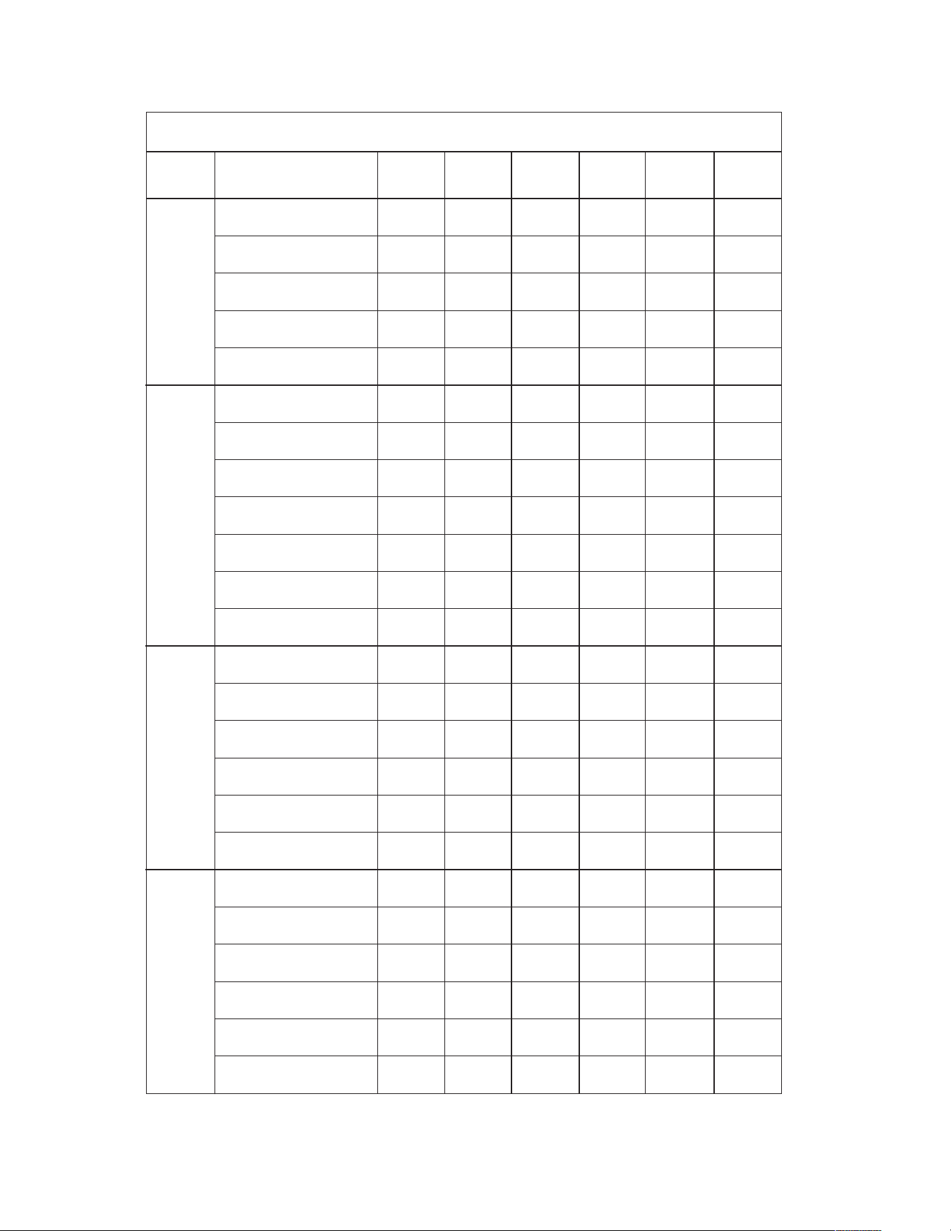
38
187-253 187-253 187-253 414-506 414-506 414-506
208/230 208/230 208/230 460 460 460
19/19 18/18 19/19 11 10 10
25/25 20/20 25/25 15 15 15
25/25 25/25 25/25 15 15 15
1111 11
208/230 208/230 208/230 460 460 460
3333 33
3450 3450 3450 3450 3450 3450
2 1/2 2 1/2 2 1/2 2 1/2 2 1/2 2 1/2
10.4/10.4 10.4/10.4 10.4/10.4 5.8 5.8 5.8
88/88 88/88 88/88 38 38 38
1111 11
208/230 208/230 208/230 460 460 460
1111 11
1/3 1/3 1/3 1/3 1/3 1/3
1.5/1.5 1.5/1.5 1.5/1.5 111
3/3 3/3 3/3 1.9 1.9 1.9
1111 11
208/230 208/230 208/230 460 460 460
1331 33
1/2 1/2 3/4 1/2 1/2 3/4
2.7/2.7 2.2/2.2 3.2/3.2 1.5 1.1 1.6
6.5/6.5 10.6/10.6 16.8/16.8 3.6 5.3 8.4
Unit Information
Compressor Motor
Condenser MotorEvaporator Fan
ELECTRICAL DATA – RJNL- SERIES
A036CK A036CL A036CM A036DK A036DL A036DM
Volts
Minimum Circuit
Ampacity
Minimum Overcurrent
Protection Device Size
Maximum Overcurrent
Protection Device Size
No.
Volts
Phase
RPM
HP, Compressor 1
Amps (RLA), Comp. 1
Amps (LRA), Comp. 1
No.
Volts
Phase
HP
Amps (FLA, each)
Amps (LRA, each)
Phase
No.
HP
Amps (FLA, each)
Volts
Amps (LRA, each)
Unit Operating
Voltage Range
XXI. MISCELLANEOUS
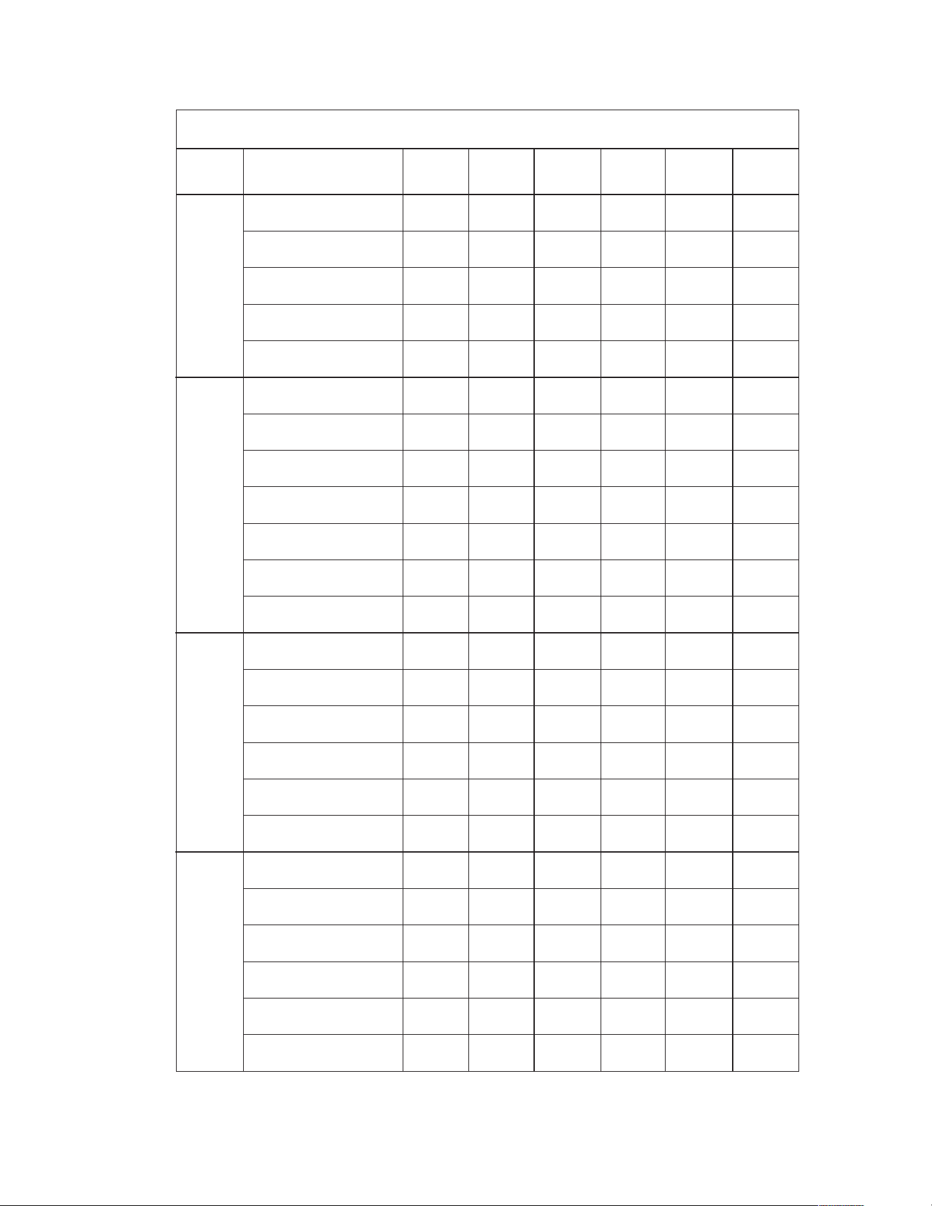
39
187-253 187-253 187-253 187-253 414-506 414-506
208/230 208/230 208/230 208/230 460 460
27/27 23/23 22/22 22/22 11 10
35/35 30/30 25/25 30/30 15 15
40/40 35/35 30/30 35/35 15 15
1111 11
208/230 208/230 208/230 208/230 460 460
1333 33
3450 3450 3450 3450 3450 3450
2 1/2 33333
16.7/16.7 13.5/13.5 13.5/13.5 13.5/13.5 66
79/79 88/88 88/88 88/88 44 44
1111 11
208/230 208/230 208/230 208/230 460 460
1111 11
1/3 1/3 1/3 1/3 1/3 1/3
1.5/1.5 1.5/1.5 1.5/1.5 1.5/1.5 11
3/3 3/3 3/3 3/3 1.9 1.9
1111 11
208/230 208/230 208/230 208/230 460 460
1133 13
1/2 1/2 1/2 3/4 1/2 1/2
2.7/2.7 2.7/2.7 2.2/2.2 3.2/3.2 1.5 1.1
6.5/6.5 6.5/6.5 10.6/10.6 16.8/16.8 3.6 5.3
Unit Information
Compressor Motor
Condenser MotorEvaporator Fan
ELECTRICAL DATA – RJNL- SERIES
A036JK A042CK A042CL A042CM A042DK A042DL
Volts
Minimum Circuit
Ampacity
Minimum Overcurrent
Protection Device Size
Maximum Overcurrent
Protection Device Size
No.
Volts
Phase
RPM
HP, Compressor 1
Amps (RLA), Comp. 1
Amps (LRA), Comp. 1
No.
Volts
Phase
HP
Amps (FLA, each)
Amps (LRA, each)
Phase
No.
HP
Amps (FLA, each)
Volts
Amps (LRA, each)
Unit Operating
Voltage Range
40
414-506 187-253 187-253 187-253 187-253 414-506
460 208/230 208/230 208/230 208/230 460
11 28/28 23/23 22/22 23/23 11
15 35/35 30/30 25/25 30/30 15
15 45/45 35/35 35/35 35/35 15
1111 11
460 208/230 208/230 208/230 208/230 460
3133 33
3450 3450 3450 3450 3450 3450
333 1/2 3 1/2 3 1/2 3 1/2
6 17.9/17.9 13.7/13.7 13.7/13.7 13.7/13.7 6.2
44 112/112 83.1/83.1 83.1/83.1 83.1/83.1 41
1111 11
460 208/230 208/230 208/230 208/230 460
1111 11
1/3 1/3 1/3 1/3 1/3 1/3
1 1.5/1.5 1.5/1.5 1.5/1.5 1.5/1.5 1
1.9 3/3 3/3 3/3 3/3 1.9
1111 11
460 208/230 208/230 208/230 208/230 460
3113 31
3/4 1/2 1/2 1/2 3/4 1/2
1.6 2.7/2.7 2.7/2.7 2.2/2.2 3.2/3.2 1.5
8.4 6.5/6.5 6.5/6.5 10.6/10.6 16.8/16.8 3.6
Unit Information
Compressor Motor
Condenser MotorEvaporator Fan
ELECTRICAL DATA – RJNL- SERIES
A042DM A042JK A048CK A048CL A048CM A048DK
Volts
Minimum Circuit
Ampacity
Minimum Overcurrent
Protection Device Size
Maximum Overcurrent
Protection Device Size
No.
Volts
Phase
RPM
HP, Compressor 1
Amps (RLA), Comp. 1
Amps (LRA), Comp. 1
No.
Volts
Phase
HP
Amps (FLA, each)
Amps (LRA, each)
Phase
No.
HP
Amps (FLA, each)
Volts
Amps (LRA, each)
Unit Operating
Voltage Range
41
414-506 414-506 187-253 187-253 187-253 187-253
460 460 208/230 208/230 208/230 208/230
11 11 33/33 25/25 26/26 26/26
15 15 40/40 30/30 30/30 30/30
15 15 50/50 40/40 40/40 40/40
1111 11
460 460 208/230 208/230 208/230 208/230
3313 33
3450 3450 3450 3450 3450 3450
3 1/2 3 1/2 3 1/2 555
6.2 6.2 21.8/21.8 16/16 16/16 16/16
41 41 117/117 110/110 110/110 110/110
1111 11
460 460 208/230 208/230 208/230 208/230
1111 11
1/3 1/3 1/3 1/3 1/3 1/3
111.5/1.5 2.2/2.2 2.2/2.2 2.2/2.2
1.9 1.9 3/3 4.7/4.7 4.7/4.7 4.7/4.7
1111 11
460 460 208/230 208/230 208/230 208/230
3311 33
1/2 3/4 1/2 1 3/4 1
1.1 1.6 2.7/2.7 7.6/7.6 3.2/3.2 3.8/3.8
5.3 8.4 6.5/6.5 0/0 16.8/16.8 24/24
Unit Information
Compressor Motor
Condenser Motor
Evaporator Fan
ELECTRICAL DATA – RJNL- SERIES
A048DL A048DM A048JK A060CK A060CL A060CM
Volts
Minimum Circuit
Ampacity
Minimum Overcurrent
Protection Device Size
Maximum Overcurrent
Protection Device Size
No.
Volts
Phase
RPM
HP, Compressor 1
Amps (RLA), Comp. 1
Amps (LRA), Comp. 1
No.
Volts
Phase
HP
Amps (FLA, each)
Amps (LRA, each)
Phase
No.
HP
Amps (FLA, each)
Volts
Amps (LRA, each)
Unit Operating
Voltage Range

42
414-506 414-506 414-506 187-253 187-253 187-253 414-506
460 460 460 208/230 208/230 208/230 460
13 13 14 39/39 34/34 34/34 17
15 15 20 45/45 40/40 40/40 20
20 20 20 60/60 50/50 50/50 25
1111 11 1
460 460 460 208/230 208/230 208/230 460
3331 33 3
3450 3450 3450 3450 3450 3450 3450
55557 1/2 7 1/2 7 1/2
7.8 7.8 7.8 26.4/26.4 21.2/21.2 21.2/21.2 10.9
52 52 52 134/134 123/123 123/123 62
1111 11 1
460 460 460 208/230 208/230 208/230 460
1111 11 1
1/3 1/3 1/3 1/3 1/3 1/3 1/3
1112.2/2.2 1.8/1.8 1.8/1.8 1
2.4 2.4 2.4 4.7/4.7 3.3/3.3 3.3/3.3 2.2
1111 11 1
460 460 460 208/230 208/230 208/230 460
1331 33 3
1 3/4 111 1/2 1 1/2 1 1/2
1.7 1.6 1.9 2.8/2.8 5.8/5.8 5.8/5.8 2.8
0 8.4 12 0/0 34/34 34/34 17
Unit Information
Compressor Motor
Condenser Motor
Evaporator Fan
ELECTRICAL DATA – RJNL- SERIES
A060DK A060DL A060DM A060JK A072CL A072CM A072DL
Volts
Minimum Circuit
Ampacity
Minimum Overcurrent
Protection Device Size
Maximum Overcurrent
Protection Device Size
No.
Volts
Phase
RPM
HP, Compressor 1
Amps (RLA), Comp. 1
Amps (LRA), Comp. 1
No.
Volts
Phase
HP
Amps (FLA, each)
Amps (LRA, each)
Phase
No.
HP
Amps (FLA, each)
Volts
Amps (LRA, each)
Unit Operating
Voltage Range
43
414-506 518-633
460 575
17 14
20 15
25 20
11
460 575
33
3450 3450
7 1/2 7 1/2
10.9 8.3
62 50
11
460 575
11
1/3 1/3
1 0.8
2.2 1.6
11
460 575
33
1 1/2 1 1/2
2.8 2.3
17 13
Unit Information
Compressor Motor
Condenser MotorEvaporator Fan
ELECTRICAL DATA – RJNL- SERIES
A072DM A072YL
Volts
Minimum Circuit
Ampacity
Minimum Overcurrent
Protection Device Size
Maximum Overcurrent
Protection Device Size
No.
Volts
Phase
RPM
HP, Compressor 1
Amps (RLA), Comp. 1
Amps (LRA), Comp. 1
No.
Volts
Phase
HP
Amps (FLA, each)
Amps (LRA, each)
Phase
No.
HP
Amps (FLA, each)
Volts
Amps (LRA, each)
Unit Operating
Voltage Range

44
187-253 187-253 187-253 414-506 414-506 414-506 187-253
1
7/17 18/18 18/18 10 10 10 24/24
20/20 20/20 25/25 15 15 15 30/30
25/25 25/25 25/25 15 15 15 40/40
1111 11 1
208/230 208/230 208/230 460 460 460 208/230
3333 33 1
2.5 2.5 2.5 2.5 2.5 2.5 2.5
3450 3450 3450 3450 3450 3450 3450
10.4/10.4 10.4/10.4 10.4/10.4 5.8 5.8 5.8 16.7/16.7
88/88 88/88 88/88 38 38 38 79/79
1111 11 1
208/230 208/230 208/230 460 460 460 208/230
1111 11 1
1/3 1/3 1/3 1/3 1/3 1/3 1/3
1.5 1.5 1.5 1111.5
3331.9 1.9 1.9 3
1111 11 1
208/230 208/230 208/230 460 460 460 208/230
1331 33 1
1/2 1/2 3/4 1/2 1/2 3/4 1/2
1.6 2.8 3.4 1.0 1.4 1.6 1.6
0 10.6 16.8 0 5.3 8.4 0
Unit Information
Compressor Motor
Condenser Motor
Evaporator Fan
ELECTRICAL DATA – RJPL- SERIES
-A036CK -A036CL -A036CM -A036DK -A036DL -A036DM -A036JK
Minimum Circuit
Ampacity
M
inimum Overcurrent
P
rotection Device Size
Maximum Overcurrent
Protection Device Size
No.
Volts
Phase
HP
RPM
Amps (RLA)
Amps (LRA)
No.
Volts
Phase
HP
Amps (FLA)
Amps (LRA)
Phase
No.
HP
Amps (FLA)
Volts
Amps (LRA)
Unit Operating
Voltage Range
45
187-253 187-253 187-253 414-506 414-506 414-506 187-253
21/21 22/22 22/22 10 10 11 26/26
25/25 25/25 30/30 15 15 15 35/35
30/30 30/30 35/35 15 15 15 40/40
1111 11 1
208/230 208/230 208/230 460 460 460 208/230
3333 33 1
3333 33 3
3450 3450 3450 3450 3450 3450 3450
13.5/13.5 13.5/13.5 13.5/13.5 66617.9/17.9
88/88 88/88 88/88 44 44 44 112/112
1111 11 1
208/230 208/230 208/230 460 460 460 208/230
1111 11 1
1/3 1/3 1/3 1/3 1/3 1/3 1/3
1.5 1.5 1.5 1111.5
3331.9 1.9 1.9 3
1111 11 1
208/230 208/230 208/230 460 460 460 208/230
1331 33 1
1/2 1/2 3/4 3/4 1/2 3/4 1/2
1.9 2.8 3.4 1.2 1.4 1.6 1.9
0 10.6 16.8 0 5.3 8.4 0
Unit Information
Compressor Motor
Condenser Motor
Evaporator Fan
ELECTRICAL DATA – RJPL- SERIES
-A042CK -A042CL -A042CM -A042DK -A042DL -A042DM -A042JK
Minimum Circuit
Ampacity
Minimum Overcurrent
Protection Device Size
Maximum Overcurrent
Protection Device Size
No.
Volts
Phase
HP
RPM
Amps (RLA)
Amps (LRA)
No.
Volts
Phase
HP
Amps (FLA)
Amps (LRA)
Phase
No.
HP
Amps (FLA)
Volts
Amps (LRA)
Unit Operating
Voltage Range

46
187-253 187-253 187-253 414-506 414-506 414-506 187-253
21/21 22/22 23/23 10 11 11 31/31
25/25 25/25 30/30 15 15 15 40/40
30/30 35/35 35/35 15 15 15 50/50
1111 11 1
208/230 208/230 208/230 460 460 460 208/230
3333 33 1
3.5 3.5 3.5 3.5 3.5 3.5 3.5
3450 3450 3450 3450 3450 3450 3450
13.7/13.7 13.7/13.7 13.7/13.7 6.2 6.2 6.2 21.8/21.8
83.1/83.1 83.1/83.1 83.1/83.1 41 41 41 117/117
1111 11 1
208/230 208/230 208/230 460 460 460 208/230
1111 11 1
1/3 1/3 1/3 1/3 1/3 1/3 1/3
1.5 1.5 1.5 1111.5
3331.9 1.9 1.9 3
1111 11 1
208/230 208/230 208/230 460 460 460 208/230
1331 33 1
1/2 1/2 3/4 3/4 1/2 3/4 1/2
1.9 2.8 3.4 1.2 1.4 1.6 1.9
0 10.6 16.8 0 5.3 8.4 0
Unit Information
Compressor Motor
Condenser Motor
Evaporator Fan
ELECTRICAL DATA – RJPL- SERIES
-A048CK -A048CL -A048CM -A048DK -A048DL -A048DM -A048JK
Minimum Circuit
Ampacity
Minimum Overcurrent
Protection Device Size
Maximum Overcurrent
Protection Device Size
No.
Volts
Phase
HP
RPM
Amps (RLA)
Amps (LRA)
No.
Volts
Phase
HP
Amps (FLA)
Amps (LRA)
Phase
No.
HP
Amps (FLA)
Volts
Amps (LRA)
Unit Operating
Voltage Range

47
187-253 187-253 187-253 414-506 414-506 414-506 187-253
25/25 26/26 26/26 13 13 13 39/39
30/30 30/30 30/30 15 15 15 45/45
40/40 40/40 40/40 20 20 20 60/60
1111 11 1
208/230 208/230 208/230 460 460 460 208/230
3333 33 1
5555 55 5
3450 3450 3450 3450 3450 3450 3450
16/16 16/16 16/16 7.8 7.8 7.8 26.4/26.4
110/110 110/110 110/110 52 52 52 134/134
1111 11 1
208/230 208/230 208/230 460 460 460 208/230
1111 11 1
1/3 1/3 1/3 1/3 1/3 1/3 1/3
2.2 2.2 2.2 1112.2
4.7 4.7 4.7 2.4 2.4 2.4 4.7
1111 11 1
208/230 208/230 208/230 460 460 460 208/230
1331 33 1
1 3/4 113/4 11
2.8 3.4 3.8 1.7 1.6 1.9 2.8
0 16.8 24 0 8.4 12 0
Unit Information
Compressor MotorCondenser Motor
Evaporator Fan
ELECTRICAL DATA – RJPL- SERIES
-A060CK -A060CL -A060CM -A060DK -A060DL -A060DM -A060JK
Minimum Circuit
Ampacity
Minimum Overcurrent
Protection Device Size
Maximum Overcurrent
Protection Device Size
No.
Volts
Phase
HP
RPM
Amps (RLA)
Amps (LRA)
No.
Volts
Phase
HP
Amps (FLA)
Amps (LRA)
Phase
No.
HP
Amps (FLA)
Volts
Amps (LRA)
Unit Operating
Voltage Range
48
INDOOR AIRFLOW PERFORMANCE FOR 3-5 TON PACKAGE HEAT PUMPS – RJNL
DIRECT DRIVE
CFM [L/s] Air Delivery/Watts-208 VOLTS
External Static Pressure-Inches W.C.
Nominal
Cooling
Capacity
Tons
Motor Speed
From Factory
Manufacturer
Recommended
Airflow Range
(Min / Max) CFM
Blower Size/
Motor HP #
of Speeds
Motor
Speed
0.10 0.20 0.30 0.40 0.50 0.60 0.70 0.80 0.90 1.00
10x10
CFM
1275 1235 1210 1181 1132 1045
3.0 Low 1050 / 1350 1/2 Low [602] [583] [571] [557] [534] [493]
3 Speed Watts 493 481 468 452 431 402
10x10
CFM
1397 1344 1319 1297 1249 1147
3.5 Low 1225 / 1575 1/2 Med [659] [634] [622] [612] [589] [541]
3 Speed Watts 561 537 522 508 488 454
10x10
CFM
1766 1719 1671 1617 1550 1465
4.0 Low 1400 / 1800 1/2 High [833] [811] [789] [763] [732] [691]
3 Speed Watts 735 719 697 671 639 603
CFM
1974 1935 1897 1860 1823 1788 1753 1719 1686
11x9 Low [932] [913] [895] [878] [860] [844] [827] [811] [796]
5.0 Low 1750 / 2250 1 Watts 490 505 510 545 555 575 600 605 625
2 Speed
CFM
2185 2148 2112 2076 2040 2005 1970 1935 1900
High [1031] [1014] [997] [980] [963] [946] [930] [913] [897]
Watts 675 685 700 720 735 750 770 780 805
CFM [L/s] Air Delivery/Watts-230/460 VOLTS
External Static Pressure-Inches W.C.
Nominal
Cooling
Capacity
Tons
Motor Speed
From Factory
Manufacturer
Recommended
Airflow Range
(Min / Max) CFM
Blower Size/
Motor HP #
of Speeds
Motor
Speed
0.10 0.20 0.30 0.40 0.50 0.60 0.70 0.80 0.90 1.00
10x10
CFM
1455 1423 1388 1345 1289 1214
3.0 Low 1050 / 1350 1/2 Low [687] [627] [655] [635] [608] [573]
3 Speed Watts 578 565 549 528 502 472
10x10
CFM
1601 1561 1517 1466 1401 1317
3.5 Med 1225 / 1575 1/2 Med [756] [737] [716] [692] [661] [622]
3 Speed Watts 659 636 613 589 562 529
10x10
CFM
1964 1902 1839 1771 1693 1602
4.0 High 1400 / 1800 1/2 High [927] [898] [868] [836] [799] [756]
3 Speed Watts 847 811 780 751 721 688
CFM
1974 1935 1897 1860 1823 1788 1753 1719 1686
11x9 Low [932] [913] [895] [878] [860] [844] [827] [811] [796]
5.0 Low 1750 / 2250 1 Watts 490 505 510 545 555 575 600 605 625
2 Speed
CFM
2185 2148 2112 2076 2040 2005 1970 1935 1900
High [1031] [1014] [997] [980] [963] [946] [930] [913] [897]
Watts 675 685 700 720 735 750 770 780 805
DIRECT-DRIVE BLOWER 208 AIRFLOW PERFORMANCE
DIRECT-DRIVE BLOWER 230/460 AIRFLOW PERFORMANCE
49
INDOOR AIRFLOW PERFORMANCE FOR 3-5 TON PACKAGE HEAT PUMPS – RJPL
DIRECT DRIVE
DIRECT-DRIVE BLOWER 208/230/460 AIRFLOW PERFORMANCE
CFM Air Delivery/RPM/Watts-208/230 Volts
External Static Pressure-Inches W.C.
0.10 0.20 0.30 0.40 0.50 0.60 0.70 0.80 0.90 1.00
CFM 1448 1413 1367 1325 1285 1242 1196 1106 1006
10x10
RPM 674 720 771 818 862 907 953 1019 1091
1/2 HP [373]
Watts 230 245 260 274 288 301 314 330 350
2 Speed
CFM 1618 1577 1516 1482 1443 1395 1359 1312 1261 1042
(X-13 Motor)
RPM 712 755 807 851 894 941 978 1019 1061 1137
Watts 299 315 332 350 364 380 391 402 414 392
CFM 1641 1603 1570 1534 1504 1468 1410 1359 1316 1252
10x10
RPM 724 764 806 852 895 933 985 1032 1076 1132
3/4 HP [559]
Watts 292 307 323 343 363 377 396 412 430 446
2 Speed
CFM 1735 1704 1674 1631 1598 1560 1527 1481 1437 1336
(X-13 Motor)
RPM 755 796 835 879 917 956 995 1044 1084 1133
Watts 340 360 378 396 411 427 443 464 479 482
CFM 1771 1739 1708 1670 1642 1607 1568 1511 1236
10x10
RPM 848 890 925 963 996 1032 1076 1121 1161
3/4 HP [559]
Watts 422 445 462 478 493 509 529 544 460
2 Speed
CFM 1954 1908 1878 1840 1797 1771 1692 1603 1457
(X-13 Motor)
RPM 914 949 984 1016 1055 1083 1114 1133 1154
Watts 547 565 585 601 619 634 634 605 550
CFM 1914 1882 1851 1817 1783 1753 1703 1688
10x10
Low RPM 778 805 835 861 894 926 959 988
1 HP [746]
Watts 496 514 533 544 565 584 604 618
2 Speed
CFM 2185 2148 2112 2076 2040 2005 1970 1935 1900
(X-13 Motor)
High RPM 846 871 895 920 950 984 1008 1042 1061
Watts 675 685 700 720 735 750 770 780 805
Nominal
Cooling
Capacity
Tons
Motor Speed
From Factor
y
Manufacturer
Recommended
Air-Flow Range
(
Min / Max
)
CFM
Blower Size/
Motor HP #
of S
p
eeds
3.5 Low (Tap 2) 1225 / 1575
Motor
S
p
eed
3.0 Low (Tap 2) 1050 / 1350
Low
High
Low
High
Low
High
5.0 Low (Tap 2) 1750 / 2250
4.0 Low (Tap 2) 1400 / 1800
CFM Air Delivery/RPM/Watts-208/230/460 Volts
50
INDOOR AIRFLOW PERFORMANCE – RJNL
L
M
N
RPM
—
—
—
—
625
655
685
730
755
790
WATTS
—
—
—
—
315
340
380
420
465
500
RPM
—
625
640
670
700
730
755
790
825
850
WATTS
—
275
300
315
330
365
390
435
475
530
RPM
665
680
710
735
770
795
825
850
875
890
WATTS
290
295
315
330
350
385
415
455
505
550
RPM
730
750
780
800
830
850
870
890
915
935
WATTS
300
310
325
345
370
400
435
490
535
570
RPM
780
805
830
850
875
890
915
935
955
975
WATTS
315
325
340
365
400
430
450
505
550
600
RPM
830
850
875
890
915
935
955
970
985
1020
WATTS
330
345
365
385
415
445
480
525
570
650
RPM
875
895
915
935
955
975
990
1005
1040
1080
WATTS
360
375
390
410
440
470
505
550
630
690
RPM
920
935
955
975
990
1010
1040
1075
1100
1125
WATTS
375
390
405
430
450
500
545
605
685
940
RPM
960
970
990
1010
1040
1070
1090
1110
1135
1165
WATTS
390
410
430
450
495
540
590
640
710
770
RPM
990
1015
1040
1060
1085
1110
1135
1160
1185
1210
WATTS
410
435
450
475
530
575
630
680
750
830
RPM
1040
1065
1080
1100
1125
1150
1180
1200
1225
1245
WATTS
445
465
485
520
565
615
660
730
800
870
RPM
1080
1100
1115
1145
1165
1195
1220
1245
1265
1290
WATTS
470
500
540
560
590
645
720
780
830
910
RPM
1140
1160
1180
1200
1220
1230
1255
1280
1295
1310
WATTS
510
530
540
600
645
685
740
800
875
930
RPM
1190
1210
1230
1250
1260
1280
1295
1325
1350
—
WATTS
540
560
600
630
675
725
785
840
910
—
RPM
1235
1255
1270
1285
1305
1325
1350
1365
—
—
WATTS
590
610
630
660
710
760
820
885
—
—
3-3.5 TON
0.1 [.02] 0.2 [.05] 0.3 [.07] 0.4 [.10] 0.5 [.12] 0.6 [.15] 0.7 [.17] 0.8 [.20] 0.9 [.22] 1.0 [.25] 1.1 [.27] 1.2 [.30] 1.3 [.32] 1.4 [.35] 1.5 [.37]
EXTERNAL STATIC PRESSURE - INCHES OF WATER
VOLTAGE 208-230, 460 - 3 PHASE
CAPACITY 3 & 3.5 TON HEAT PUMP (13 SEER)
AIR
FLOW
CFM
[L/s]
900
[425]
1000
[472]
1100
[519]
1200
[566]
1300
[614]
1400
[661]
1500
[708]
1600
[755]
1700
[802]
1800
[850]
L
N
M
RPM
—
—
—
690
720
750
780
820
850
WATTS
—
—
—
360
390
430
475
520
585
RPM
—
695
725
750
780
810
840
870
900
WATTS
—
330
350
390
430
465
515
560
610
RPM
745
770
795
820
850
870
895
925
950
WATTS
340
365
395
425
460
485
540
580
630
RPM
810
835
855
875
895
920
945
970
1000
WATTS
375
395
420
450
480
500
555
600
665
RPM
865
880
895
920
945
970
990
1015
1045
WATTS
390
415
435
465
500
530
600
640
715
RPM
900
920
945
970
990
1015
1035
1060
1090
WATTS
400
435
455
480
530
570
625
690
760
RPM
945
975
995
1010
1035
1055
1080
1115
1130
WATTS
420
455
470
500
565
600
660
750
810
RPM
1000
1010
1030
1055
1075
1090
1115
1145
1170
WATTS
440
470
500
560
590
645
710
790
865
RPM
1040
1060
1070
1100
1115
1140
1155
1185
1205
WATTS
460
490
520
580
635
695
740
835
900
RPM
1075
1100
1115
1140
1160
1180
1205
1225
1255
WATTS
490
530
560
630
680
735
800
880
965
RPM
1115
1140
1160
1180
1205
1225
1250
1275
1300
WATTS
540
570
600
660
725
790
860
900
1050
RPM
1170
1190
1205
1230
1250
1270
1295
1315
1340
WATTS
580
600
640
700
770
845
930
1010
1100
RPM
1215
1235
1250
1270
1290
1315
1340
1355
1365
WATTS
620
640
685
760
830
910
995
1060
1140
RPM
1260
1270
1290
1315
1335
1350
1365
—
—
WATTS
650
685
745
815
890
960
1030
—
—
RPM
1300
1315
1335
1350
1365
—
—
—
—
WATTS
685
740
810
865
935
—
—
—
—
4 TON
0.1 [.02] 0.2 [.05] 0.3 [.07] 0.4 [.10] 0.5 [.12] 0.6 [.15] 0.7 [.17] 0.8 [.20] 0.9 [.22] 1.0 [.25] 1.1 [.27] 1.2 [.30] 1.3 [.32] 1.4 [.35] 1.5 [.37]
EXTERNAL STATIC PRESSURE - INCHES OF WATER
VOLTAGE 208-230, 460 - 3 PHASE
CAPACITY 4 TON HEAT PUMP (13 SEER)
AIR
FLOW
CFM
[L/s]
1200
[566]
1300
[614]
1400
[661]
1500
[708]
1600
[755]
1700
[802]
1800
[850]
1900
[897]
2000
[944]
DRIVE PACKAGE L M N (FIELD-SUPPLIED)
MOTOR H.P. 1/2 (3/4 - 575V) 3/4 3/4
BLOWER SHEAVE 6.9 PITCH DIAMETER 6.4 PITCH DIAMETER 6.4 PITCH DIAMETER
MOTOR SHEAVE ADJUSTABLE 2.4 - 3.4 PITCH DIAMETER ADJUSTABLE 3.4 - 4.4 PITCH DIAMETER ADJUSTABLE 4.0 - 5.0 PITCH DIAMETER
TURNS OPEN 0 1 2 3 4 5 6 0 1 2 3 4 5 6
RPM 935 875 830 780 730 680 625 1295 1230 1185 1135 1085 1000 955 RPM RANGE 1090 - 1365
Factory sheave settngs are shown in bold print.
Factory sheave settngs are shown in bold print.
NOTE: Bold lines separate L, M and N drives respectively.
NOTE: Bold lines separate L, M and N drives respectively.
DRIVE PACKAGE L M N (FIELD-SUPPLIED)
MOTOR H.P. 1/2 (3/4 - 575V) 3/4 3/4
BLOWER SHEAVE 6.9 PITCH DIAMETER 6.4 PITCH DIAMETER 6.4 PITCH DIAMETER
MOTOR SHEAVE ADJUSTABLE 2.8 - 3.8 PITCH DIAMETER ADJUSTABLE 3.4 - 4.4 PITCH DIAMETER ADJUSTABLE 4.0 - 5.0 PITCH DIAMETER
TURNS OPEN 0 1 2 3 4 5 6 0 1 2 3 4 5 6
RPM 990 945 895 850 800 750 695 1270 1225 1170 1115 1065 1015 965 RPM RANGE 1090 - 1365
51
INDOOR AIRFLOW PERFORMANCE – RJNL
“M”
“
L”
RPM
—
—
—
—
780
800
830
860
895
940
970
WATTS
—
—
—
—
455
485
550
615
680
755
825
RPM
—
—
780
795
815
850
880
915
945
975
1015
WATTS
—
—
390
450
470
530
605
655
735
795
880
RPM
780
795
805
840
870
895
930
955
995
1015
1040
WATTS
370
405
425
490
540
590
655
705
780
830
925
RPM
815
840
870
895
915
945
970
1005
1030
1065
1100
WATTS
385
415
470
530
540
640
700
760
830
910
1005
RPM
875
895
915
940
965
995
1015
1040
1060
1100
1145
WATTS
425
440
510
570
675
675
730
820
880
965
1055
RPM
930
945
965
990
1010
1035
1055
1090
1120
1150
1175
WATTS
460
500
560
605
660
720
790
870
940
1025
1085
RPM
970
995
1015
1035
1055
1070
1105
1130
1155
1180
1225
WATTS
490
540
600
640
710
775
830
910
980
1050
1140
RPM
1030
1045
1060
1075
1100
1120
1145
1170
1195
1225
1260
WATTS
540
595
640
680
760
810
875
950
1020
1095
1175
RPM
1065
1080
1105
1120
1140
1160
1180
1210
1240
1265
1300
WATTS
570
615
680
725
785
850
910
995
1055
1125
1210
RPM
1105
1135
1145
1160
1175
1200
1225
1250
1275
1310
1340
WATTS
595
650
705
755
810
890
950
1020
1100
1175
1255
RPM
1150
1165
1180
1200
1225
1245
1260
1290
1320
1350
1370
WATTS
615
675
730
790
850
915
980
1060
1140
1230
1315
RPM
1195
1215
1225
1245
1260
1290
1320
1335
1360
1375
1400
WATTS
645
700
750
815
880
960
1035
1100
1180
1260
1375
RPM
1235
1255
1275
1300
1320
1335
1350
1370
1385
1405
—
WATTS
660
735
790
855
930
1000
1075
1150
1225
1320
—
RPM
1300
1320
1340
1355
1365
1375
1385
1400
—
—
—
WATTS
705
775
840
905
985
1050
1120
1200
—
—
—
RPM
1340
1355
1365
1375
1390
1405
—
—
—
—
—
WATTS
745
805
880
940
1020
1100
—
—
—
—
—
0.1 [.02] 0.2 [.05] 0.3 [.07] 0.4 [.10] 0.5 [.12] 0.6 [.15] 0.7 [.17] 0.8 [.20] 0.9 [.22] 1.0 [.25] 1.10 [.27] 1.20 [.30] 1.30 [.32] 1.40 [.35] 1.50 [.37]
EXTERNAL STATIC PRESSURE–INCHES OF WATER
VOLTAGE 208-230, 460 - 3 PHASE
CAPACITY5 TON - 13 SEER
AIR
FLOW
CFM
[L/s]
1400
[661]
1500
[708]
1600
[755]
1700
[802]
1800
[850]
1900
[897]
2000
[944]
2100
[991]
2200
[1038]
2300
[1085]
2400
[1133]
DRIVE PACKAGE “L” “M”
MOTOR H.P. 3/4 1
BLOWER SHEAVE 6.4 PITCH DIAMETER 6.4 PITCH DIAMETER
MOTOR SHEAVE 2.8-3.8 PITCH DIAMETER - ADJ. 3.4-4.4 PITCH DIAMETER - ADJ.
TURNS OPEN 0 1 2 3 4 5 6 0 1 2 3 4 5 6
RPM 1095 1040 995 940 890 835 780 1405 1360 1305 1250 1195 1145 1095
5 TON
NOTE: L-Drive left of bold line, M-Drive right of bold line.
Factory sheave settings are shown in bold.
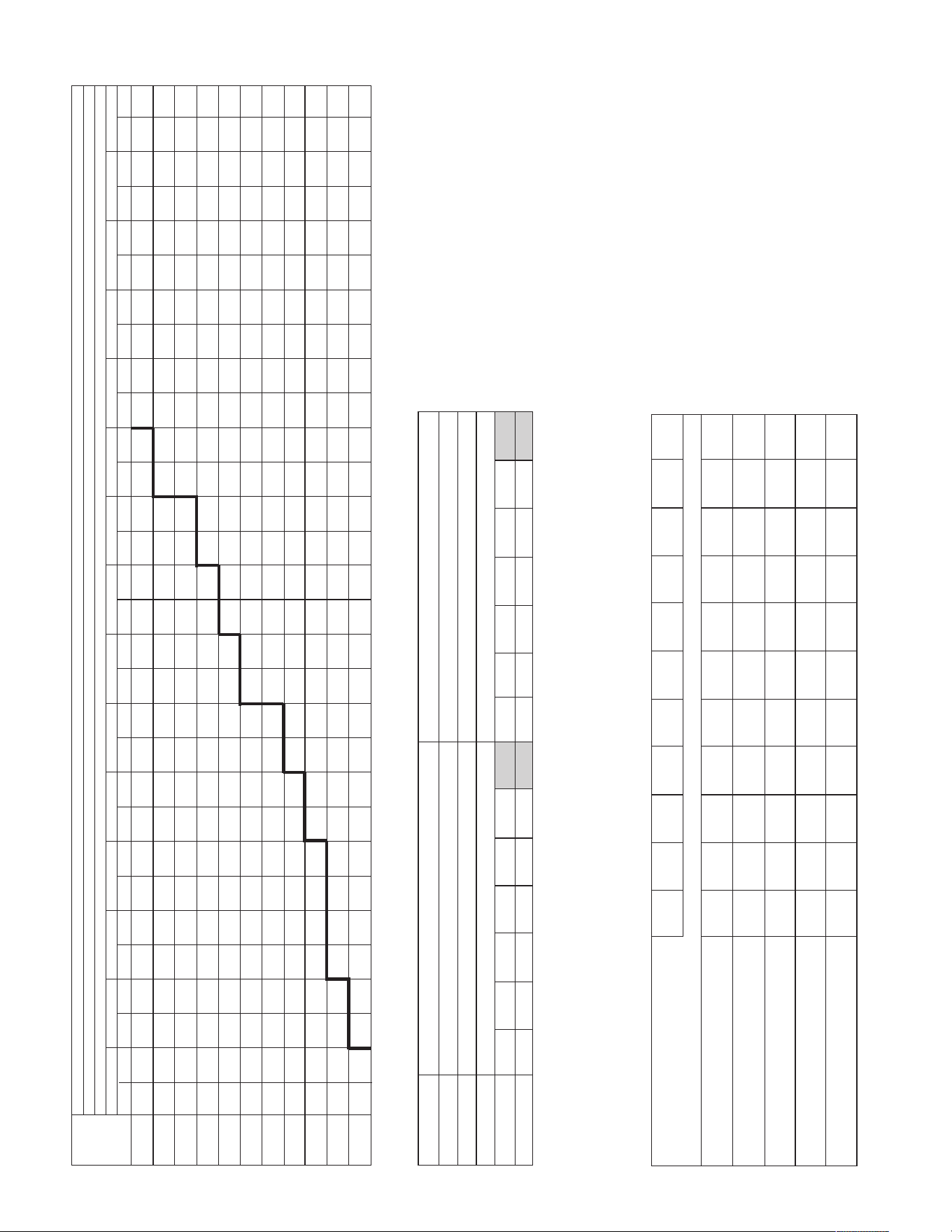
52
INDOOR AIRFLOW PERFORMANCE – RJNL
RPM
—
—
—
854
885
917
950
985
1020
1057
1096
W
—
—
—
762
834
917
1009
1112
1224
1345
1477
RPM
—
—
862
890
920
951
983
1017
1052
1088
1125
W
—
—
731
797
873
959
1055
1160
1276
1401
1536
RPM
847
872
899
926
955
985
1016
1049
1083
1118
1154
W
656
706
766
835
914
1004
1103
1211
1330
1458
1597
RPM
886
910
935
962
990
1019
1049
1081
1114
1148
1183
W
687
740
803
876
958
1051
1153
1265
1387
1519
1660
RPM
924
947
971
997
1024
1052
1081
1112
1144
1177
1211
W
720
776
842
919
1004
1100
1206
1321
1446
1582
1726
RPM
962
984
1007
1032
1058
1085
1113
1143
1174
1206
1240
W
755
815
885
964
1053
1152
1261
1380
1508
1647
1795
RPM
999
1020
1043
1066
1091
1118
1145
1174
1204
1235
1267
W
793
856
929
1012
1104
1207
1319
1441
1573
1715
1866
RPM
1036
1057
1078
1101
1125
1150
1176
1204
1233
1263
1295
W
834
900
976
1062
1158
1264
1379
1505
1640
1785
1940
RPM
1073
1092
1113
1135
1158
1182
1207
1234
1262
1291
1322
W
877
947
1026
1115
1214
1323
1442
1571
1709
1858
2016
RPM
1110
1128
1147
1168
1190
1213
1238
1264
1291
1319
—
W
923
995
1078
1171
1273
1385
1508
1639
1781
1933
—
RPM
1146
1163
1181
1201
1222
1245
1268
1293
1319
1346
—
W
971
1047
1133
1229
1334
1450
1575
1711
1856
2011
—
RPM
1181
1198
1215
1234
1254
1276
1298
1322
1347
—
—
W
1021
1101
1190
1289
1398
1517
1646
1784
1933
—
—
RPM
1217
1232
1249
1267
1286
1306
1328
1351
1375
—
—
W
1074
1157
1250
1352
1465
1587
1719
1861
2012
—
—
RPM
1252
1266
1282
1299
1317
1336
1357
1379
—
—
—
W
1130
1216
1312
1418
1533
1659
1794
1939
—
—
—
RPM
1287
1300
1315
1331
1348
1366
1386
1407
—
—
—
W
1188
1277
1377
1486
1605
1733
1872
2020
—
—
—
0.1 [.02] 0.2 [.05] 0.3 [.07] 0.4 [.10] 0.5 [.12] 0.6 [.15] 0.7 [.17] 0.8 [.20] 0.9 [.22] 1.0 [.25] 1.1 [.27] 1.2 [.30] 1.3 [.32] 1.4 [.35] 1.5 [.37]
External Static Pressure — Inches of Water [kPa]
Voltage 208/230, 460, 575 — 3 Phase
Model RJNL-A072
Air Flow
CFM [L/s]
1900 [897]
2000 [944]
2100 [991]
2200 [1038]
2300 [1085]
2400 [1133]
2500 [1180]
2600 [1227]
2700 [1274]
2800 [1321]
2900 [1368]
Drive Package L M
Motor H.P. [W] 1.5 [1118.5] 1.5 [1118.5]
Blower Sheave AK66 AK66
Motor Sheave 1VP-44 1VP-50
Turns Open 0 1 2 3 4 5 6 0 1 2 3 4 5 6
RPM 1103 1052 1002 956 900 849 1 1381 1326 1272 1220 1163 1108 1
AIRFLOW PERFORMANCE — 6 TON [21.1kW] — SIDEFLOW
COMPONENT AIRFLOW RESISTANCE — 6 TON [21.1kW]
NOTE: L-Drive left of bold line, M-Drive right of bold line.
NOTES: 1. Factory sheave settings are shown in bold type.
2. Do not set motor sheave below minimum or above maximum turns open shown.
3. Re-adjustment of sheave required to achieve rated airflow at ARI minimum External Static Pressure
4. Drive data shown is for horizontal airflow with dry coil. Add component resistance (below) to duct resistance to determine total External Static Pressure.
CFM
[L/s]
Wet Coil
Downflow
Downflow Economizer RA Damper Open
Horizontal Economizer RA Damper Open
Concentric Grill RXRN-FA65 or RXRN-FA75 &
Transition RXMC-CC04
1900 2000 2100 2200 2300 2400 2500 2600 2700 2800 2900
[897] [944] [991] [1038] [1085] [1133] [1180] [1227] [1274] [1321] 1368]
0.05 0.06 0.07 0.08 0.08 0.09 0.10 0.10 0.11 0.11 0.12
[.01] [.01] [.02] [.02] [.02] [.02] [.02] [.02] [.03] [.03] [.03]
0.03 0.04 0.05 0.06 0.07 0.08 0.08 0.09 0.09 0.10 0.10
[.01] [.01] [.01] [.01] [.02] [.02] [.02] [.02] [.02] [.02] [.02]
0.08 0.08 0.09 0.09 0.10 0.10 0.10 0.11 0.11 0.12 0.12
[.02] [.02] [.02] [.02] [.02] [.02] [.02] [.03] [.03] [.03] [.03]
0.08 0.08 0.09 0.09 0.10 0.10 0.10 0.11 0.11 0.12 0.12
[.02] [.02] [.02] [.02] [.02] [.02] [.02] [.03] [.03] [.03] [.03]
0.07 0.08 0.09 0.10 0.12 0.13 0.15 0.17 0.19 0.21 0.23
[.02] [.02] [.02] [.02] [.03] [.03] [.04] [.04] [.05] [.05] [.06]
Resistance — Inches of Water [kPa]
[ ] Designates Metric Conversions
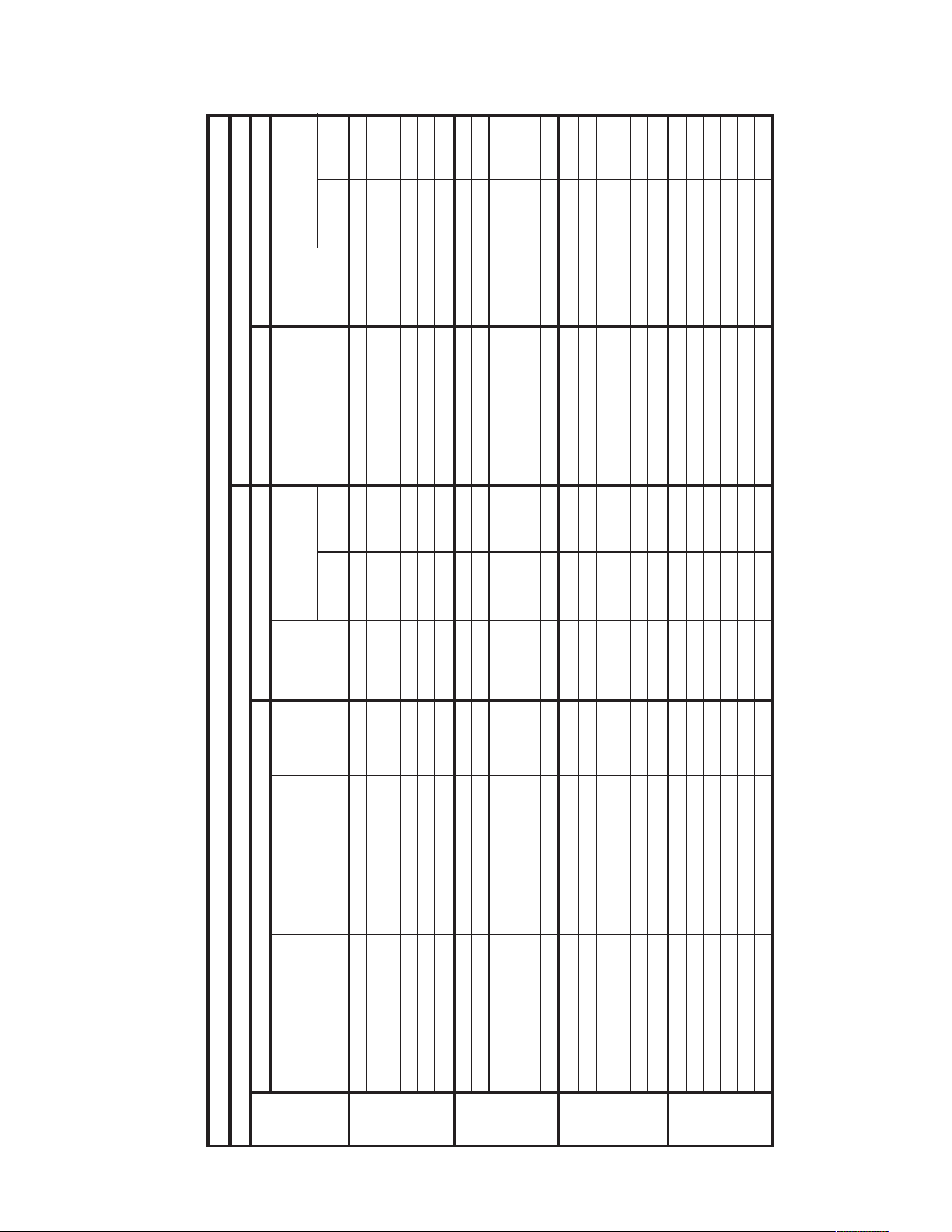
53
AUXILIARY ELECTRIC HEATER KITS CHARACTERISTICS AND APPLICATION – RJNL
No Heat — — — — 27/27 35/40 35/40 — — 27/27 35/40 35/40
A06J 1 4.2/5.6 14.33/19.1 20.2/23.3 53/57 60/60 60/60 26/30 30/30 27/27 35/40 35/40
A10J 1 7.2/9.6 24.56/32.75 34.6/40 71/77 70/70 80/80 44/50 45/50 27/27 35/40 35/40
A12J 1 8.4/11.2 28.66/38.21 40.4/46.7 78/86 80/80 90/90 51/59 60/60 27/27 35/40 35/40
A15J 1 10.8/14.4 36.84/49.13 51.9/60 92/102 100/100 110/110 65/75 70/80 27/27 35/40 35/40
A20J 1 14.4/19.2 49.13/65.5 69.3/80 114/127 125/125 150/150 87/100 90/100 27/27 35/40 35/40
No Heat — — — — 28/28 35/45 35/45 — — 28/28 35/45 35/45
A06J 1 4.2/5.6 14.33/19.1 20.2/23.3 54/58 60/60 60/60 26/30 30/30 28/28 35/45 35/45
A10J 1 7.2/9.6 24.56/32.75 34.6/40 72/78 80/80 80/80 44/50 45/50 28/28 35/45 35/45
A12J 1 8.4/11.2 28.66/38.21 40.4/46.7 79/87 80/80 90/90 51/59 60/60 28/28 35/45 35/45
A15J 1 10.8/14.4 36.84/49.13 51.9/60 93/103 100/100 110/110 65/75 70/80 28/28 35/45 35/45
A20J 1 14.4/19.2 49.13/65.5 69.3/80 115/128 125/125 150/150 87/100 90/100 28/28 35/45 35/45
No Heat — — — — 33/33 40/50 40/50 — — 33/33 40/50 40/50
A06J 1 4.2/5.6 14.33/19.1 20.2/23.3 59/63 60/70 70/70 26/30 30/30 33/33 40/50 40/50
A10J 1 7.2/9.6 24.56/32.75 34.6/40 77/83 80/80 90/90 44/50 45/50 33/33 40/50 40/50
A12J 1 8.4/11.2 28.66/38.21 40.4/46.7 84/92 90/90 100/100 51/59 60/60 33/33 40/50 40/50
A15J 1 10.8/14.4 36.84/49.13 51.9/60 98/108 100/100 110/110 65/75 70/80 33/33 40/50 40/50
A20J 1 14.4/19.2 49.13/65.5 69.3/80 120/133 125/125 150/150 87/100 90/100 33/33 40/50 40/50
No Heat — — — — 39/39 45/60 45/60 — — 39/39 45/60 45/60
A06J 1 4.2/5.6 14.33/19.1 20.2/23.3 65/69 70/80 70/80 26/30 30/30 39/39 45/60 45/60
A10J 1 7.2/9.6 24.56/32.75 34.6/40 83/89 90/90 90/100 44/50 45/50 39/39 45/60 45/60
A12J 1 8.4/11.2 28.66/38.21 40.4/46.7 90/98 90/100 100/110 51/59 60/60 39/39 45/60 45/60
A15J 1 10.8/14.4 36.84/49.13 51.9/60 104/114 110/110 125/125 65/75 70/80 39/39 45/60 45/60
A20J 1 14.4/19.2 49.13/65.5 69.3/80 126/139 150/150 150/150 87/100 90/100 39/39 45/60 45/60
208-240 VOLT, THREE PHASE, 60 HZ, AUXILIARY ELECTRIC HEATER KITS CHARACTERISTICS AND APPLICATION
Single Power Supply For Both Unit And Heater Kit
Separate Power Supply For Both Unit And Heater Kit
Unit
Model
Number
RXJJ-
Heater Kit
Nominal kW
No. of
Sequence
Steps
Rated Heater
kW @
208/240 V
Heater
KBTU/Hr @
208/240 V
Heater
Amp. @
208/240 V
Unit Min. Ckt
Ampacity @
208-240V
Min/Max
@ 208 V
Min/Max
@240 V
Over Current
Protective Device Size
Min. Ckt.
Ampacity
208/240V
Max. Fuse
Size
208/240V
Min. Circuit
Ampacity
208/240V
Min/Max
@ 208 V
Min/Max
@ 240 V
Over Current
Protective Device Size
RJNL-
A036JK
RJNL-
A042JK
RJNL-
A048JK
RJNL-
A060JK
Heater Kit
Heat Pump
Heater Kit
Heat Pump
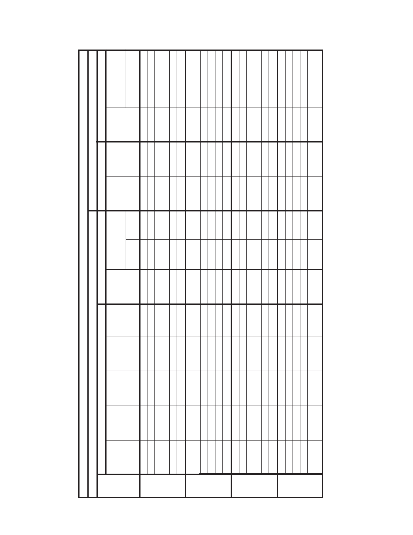
54
AUXILIARY ELECTRIC HEATER KITS CHARACTERISTICS AND APPLICATION – RJNL
No Heat — — — — 19/19 25/25 25/25 — — 19/19 25/25 25/25
A06C 1 4.2/5.6 14.33/19.1 11.7/13.5 34/36 35/35 40/40 15/17 15/20 19/19 25/25 25/25
A10C 1 7.2/9.6 24.56/32.75 20/23.1 44/48 45/45 50/50 25/29 25/30 19/19 25/25 25/25
A12C 1 8.4/11.2 28.66/38.21 23.4/27 49/53 50/50 60/60 30/34 30/35 19/19 25/25 25/25
A15C 1 10.8/14.4 36.84/49.13 30.1/34.7 57/63 60/60 70/70 38/44 40/45 19/19 25/25 25/25
A20C 1 14.4/19.2 49.13/65.5 40/46.3 69/77 70/70 80/80 50/58 50/60 19/19 25/25 25/25
No Heat — — — — 23/23 30/35 30/35 — — 23/23 30/35 30/35
A06C 1 4.2/5.6 14.33/19.1 11.7/13.5 38/40 40/45 40/45 15/17 15/20 23/23 30/35 30/35
A10C 1 7.2/9.6 24.56/32.75 20/23.1 48/52 50/50 60/60 25/29 25/30 23/23 30/35 30/35
A12C 1 8.4/11.2 28.66/38.21 23.4/27 53/57 60/60 60/60 30/34 30/35 23/23 30/35 30/35
A15C 1 10.8/14.4 36.84/49.13 30.1/34.7 61/67 60/60 70/70 38/44 40/45 23/23 30/35 30/35
A20C 1 14.4/19.2 49.13/65.5 40/46.3 73/81 80/80 80/80 50/58 50/60 23/23 30/35 30/35
No Heat — — — — 23/23 30/35 30/35 — — 23/23 30/35 30/35
A06C 1 4.2/5.6 14.33/19.1 11.7/13.5 38/40 40/45 40/45 15/17 15/20 23/23 30/35 30/35
A10C 1 7.2/9.6 24.56/32.75 20/23.1 48/52 50/50 60/60 25/29 25/30 23/23 30/35 30/35
A12C 1 8.4/11.2 28.66/38.21 23.4/27 53/57 60/60 60/60 30/34 30/35 23/23 30/35 30/35
A15C 1 10.8/14.4 36.84/49.13 30.1/34.7 61/67 60/60 70/70 38/44 40/45 23/23 30/35 30/35
A20C 1 14.4/19.2 49.13/65.5 40/46.3 73/81 80/80 90/90 50/58 50/60 23/23 30/35 30/35
No Heat — — — — 25/25 30/40 30/40 — — 25/25 30/40 30/40
A06C 1 4.2/5.6 14.33/19.1 11.7/13.5 40/42 50/50 50/50 15/17 15/20 25/25 30/40 30/40
A10C 1 7.2/9.6 24.56/32.75 20/23.1 50/54 60/60 70/70 25/29 25/30 25/25 30/40 30/40
A12C 1 8.4/11.2 28.66/38.21 23.4/27 55/59 70/70 70/70 30/34 30/35 25/25 30/40 30/40
A15C 1 10.8/14.4 36.84/49.13 30.1/34.7 63/69 70/70 80/80 38/44 40/45 25/25 30/40 30/40
A20C 1 14.4/19.2 49.13/65.5 40/46.3 75/83 90/90 100/100 50/58 50/60 25/25 30/40 30/40
208-240 VOLT, THREE PHASE, 60 HZ, AUXILIARY ELECTRIC HEATER KITS CHARACTERISTICS AND APPLICATION
Single Power Supply For Both Unit And Heater Kit
Separate Power Supply For Both Unit And Heater Kit
Unit
Model
Number
RXJJ-
Heater Kit
Nominal kW
No. of
Sequence
Steps
Rated Heater
kW @
208/240 V
Heater
KBTU/Hr @
208/240 V
Heater
Amp. @
208-240 V
Unit Min. Ckt
Ampacity @
208-240V
Min/Max
@ 208 V
Min/Max
@240 V
Over Current
Protective Device Size
Min. Ckt.
Ampacity
208/240V
Max. Fuse
Size
208/240V
Min. Circuit
Ampacity
208/240V
Min/Max
@ 208 V
Min/Max
@ 240 V
Over Current
Protective Device Size
RJNL-
A036CK
RJNL-
A042CK
RJNL-
A048CK
RJNL-
A060CK
Heater Kit
Heat Pump
Heater Kit
Heat Pump
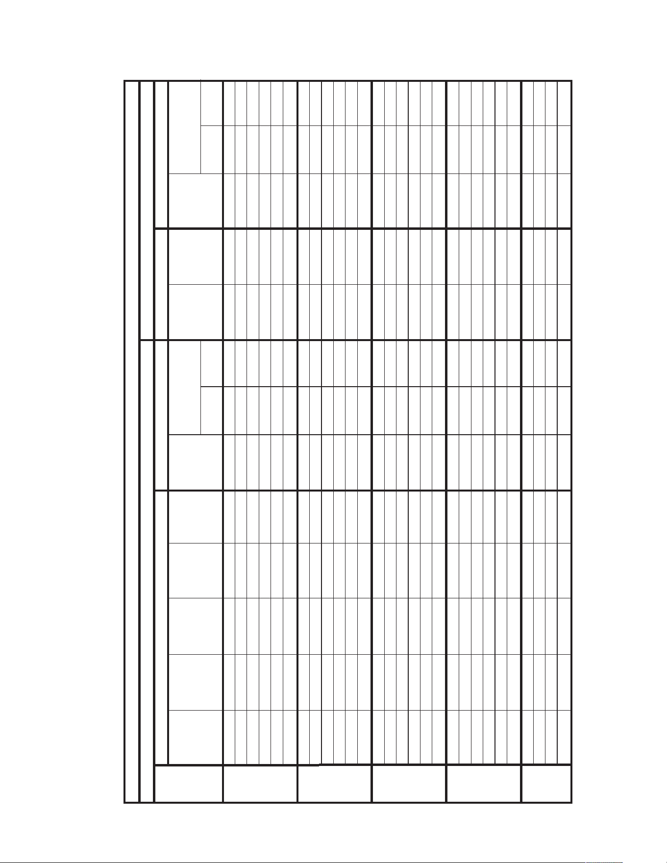
55
AUXILIARY ELECTRIC HEATER KITS CHARACTERISTICS AND APPLICATION – RJNL
No Heat — — — — 18/18 20/25 20/25 — — 18/18 20/25 20/25
A06C 1 4.2/5.6 14.33/19.1 11.7/13.5 33/35 35/35 35/40 15/17 15/20 18/18 20/25 20/25
A10C 1 7.2/9.6 24.56/32.75 20/23.1 43/47 45/45 50/50 25/29 25/30 18/18 20/25 20/25
A12C 1 8.4/11.2 28.66/38.21 23.4/27 48/52 50/50 60/60 30/34 30/35 18/18 20/25 20/25
A15C 1 10.8/14.4 36.84/49.13 30.1/34.7 56/62 60/60 70/70 38/44 40/45 18/18 20/25 20/25
A20C 1 14.4/19.2 49.13/65.5 40/46.3 68/76 70/70 80/80 50/58 50/60 18/18 20/25 20/25
No Heat — — — — 22/22 25/30 25/30 — — 22/22 25/30 25/30
A06C 1 4.2/5.6 14.33/19.1 11.7/13.5 37/39 40/45 40/45 15/17 15/20 22/22 25/30 25/30
A10C 1 7.2/9.6 24.56/32.75 20/23.1 47/51 50/50 60/60 25/29 25/30 22/22 25/30 25/30
A12C 1 8.4/11.2 28.66/38.21 23.4/27 52/56 60/60 60/60 30/34 30/35 22/22 25/30 25/30
A15C 1 10.8/14.4 36.84/49.13 30.1/34.7 60/66 60/60 70/70 38/44 40/45 22/22 25/30 25/30
A20C 1 14.4/19.2 49.13/65.5 40/46.3 72/80 80/80 80/80 50/58 50/60 22/22 25/30 25/30
No Heat — — — — 22/22 25/35 25/35 — — 22/22 25/35 25/35
A06C 1 4.2/5.6 14.33/19.1 11.7/13.5 37/39 40/45 40/45 15/17 15/20 22/22 25/35 25/35
A10C 1 7.2/9.6 24.56/32.75 20/23.1 47/51 50/50 60/60 25/29 25/30 22/22 25/35 25/35
A12C 1 8.4/11.2 28.66/38.21 23.4/27 52/56 60/60 60/60 30/34 30/35 22/22 25/35 25/35
A15C 1 10.8/14.4 36.84/49.13 30.1/34.7 60/66 60/60 70/70 38/44 40/45 22/22 25/35 25/35
A20C 1 14.4/19.2 49.13/65.5 40/46.3 72/80 80/80 80/80 50/58 50/60 22/22 25/35 25/35
No Heat — — — — 26/26 30/40 30/40 — — 26/26 30/40 30/40
A06C 1 4.2/5.6 14.33/19.1 11.7/13.5 41/43 45/50 45/50 15/17 15/20 26/26 30/40 30/40
A10C 1 7.2/9.6 24.56/32.75 20/23.1 51/55 60/60 60/60 25/29 25/30 26/26 30/40 30/40
A12C 1 8.4/11.2 28.66/38.21 23.4/27 56/60 60/60 70/70 30/34 30/35 26/26 30/40 30/40
A15C 1 10.8/14.4 36.84/49.13 30.1/34.7 64/70 70/70 80/80 38/44 40/45 26/26 30/40 30/40
A20C 1 14.4/19.2 49.13/65.5 40/46.3 76/84 80/80 90/90 50/58 50/60 26/26 30/40 30/40
No Heat — — — — 34/34 40/50 40/50 — — 34/34 40/50 40/50
A15C 1 10.8/14.4 36.84/49.13 30.1/34.7 72/78 80/80 80/80 38/44 40/45 34/34 40/50 40/50
A20C 1 14.4/19.2 49.13/65.5 40/46.3 84/92 90/90 100/100 50/58 50/60 34/34 40/50 40/50
A24C 1 18/24 61.41/81.88 50/57.7 97/107 100/100 110/110 63/73 70/80 34/34 40/50 40/50
208/240 VOLT, THREE PHASE, 60 HZ, AUXILIARY ELECTRIC HEATER KITS CHARACTERISTICS AND APPLICATION
Single Power Supply For Both Unit And Heater Kit
Separate Power Supply For Both Unit And Heater Kit
Unit
Model
Number
RXJJ-
Heater Kit
Nominal kW
No. of
Sequence
Steps
Rated Heater
kW @
208/240 V
Heater
KBTU/Hr @
208/240 V
Heater
Amp. @
208/240 V
Unit Min. Ckt
Ampacity @
208-240V
Min/Max
@ 280 V
Min/Max
@ 240 V
Over Current
Protective Device Size
Min. Ckt.
Ampacity
208/240V
Max. Fuse
Size
208/240V
Min. Circuit
Ampacity
208/240V
Min/Max
@ 208 V
Min/Max
@ 240 V
Over Current
Protective Device Size
RJNL-
A036CL
RJNL-
A042CL
RJNL-
A048CL
RJNL-
A060CL
A072CL
Heater Kit
Heat Pump
Heater Kit
Heat Pump
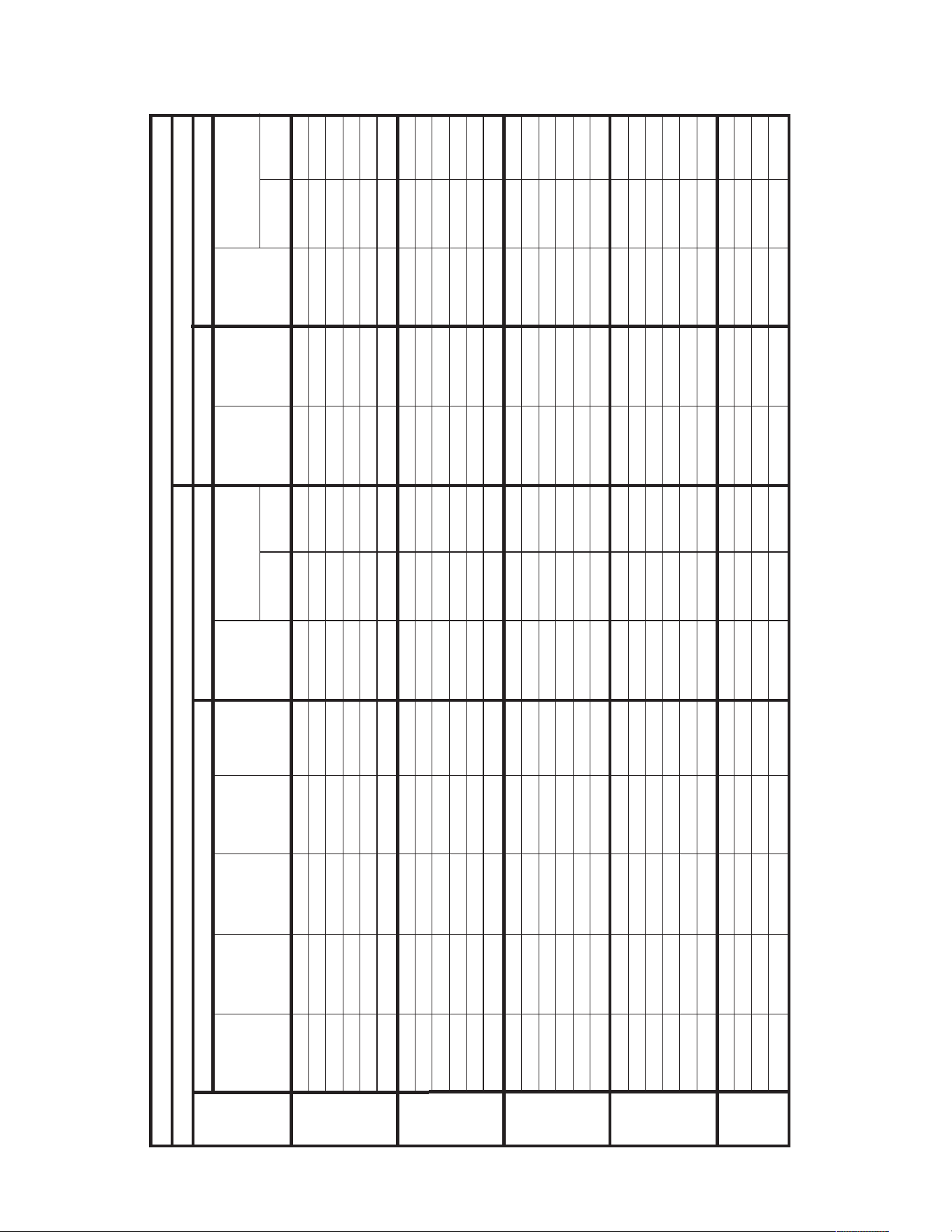
56
AUXILIARY ELECTRIC HEATER KITS CHARACTERISTICS AND APPLICATION – RJNL
No Heat — — — — 19/19 25/25 25/25 — — 19/19 25/25 25/25
A06C 1 4.2/5.6 14.33/19.1 11.7/13.5 34/36 35/35 40/40 15/17 15/20 19/19 25/25 25/25
A10C 1 7.2/9.6 24.56/32.75 20/23.1 44/48 45/45 50/50 25/29 25/30 19/19 25/25 25/25
A12C 1 8.4/11.2 28.66/38.21 23.4/27 49/53 50/50 60/60 30/34 30/35 19/19 25/25 25/25
A15C 1 10.8/14.4 36.84/49.13 30.1/34.7 57/63 60/60 70/70 38/44 40/45 19/19 25/25 25/25
A20C 1 14.4/19.2 49.13/65.5 40/46.3 69/77 70/70 80/80 50/58 50/60 19/19 25/25 25/25
No Heat — — — — 22/22 30/35 30/35 — — 22/22 30/35 30/35
A06C 1 4.2/5.6 14.33/19.1 11.7/13.5 37/39 40/45 40/45 15/17 15/20 22/22 30/35 30/35
A10C 1 7.2/9.6 24.56/32.75 20/23.1 47/51 50/50 60/60 25/29 25/30 22/22 30/35 30/35
A12C 1 8.4/11.2 28.66/38.21 23.4/27 52/56 60/60 60/60 30/34 30/35 22/22 30/35 30/35
A15C 1 10.8/14.4 36.84/49.13 30.1/34.7 60/66 70/70 70/70 38/44 40/45 22/22 30/35 30/35
A20C 1 14.4/19.2 49.13/65.5 40/46.3 72/80 80/80 90/90 50/58 50/60 22/22 30/35 30/35
No Heat — — — — 23/23 30/35 30/35 — — 23/23 30/35 30/35
A06C 1 4.2/5.6 14.33/19.1 11.7/13.5 38/40 40/45 40/45 15/17 15/20 23/23 30/35 30/35
A10C 1 7.2/9.6 24.56/32.75 20/23.1 48/52 50/50 60/60 25/29 25/30 23/23 30/35 30/35
A12C 1 8.4/11.2 28.66/38.21 23.4/27 53/57 60/60 60/60 30/34 30/35 23/23 30/35 30/35
A15C 1 10.8/14.4 36.84/49.13 30.1/34.7 61/67 70/70 70/70 38/44 40/45 23/23 30/35 30/35
A20C 1 14.4/19.2 49.13/65.5 40/46.3 73/81 80/80 90/90 50/58 50/60 23/23 30/35 30/35
No Heat — — — — 26/26 30/40 30/40 — — 26/26 30/40 30/40
A06C 1 4.2/5.6 14.33/19.1 11.7/13.5 41/43 45/50 45/50 15/17 15/20 26/26 30/40 30/40
A10C 1 7.2/9.6 24.56/32.75 20/23.1 51/55 60/60 60/60 25/29 25/30 26/26 30/40 30/40
A12C 1 8.4/11.2 28.66/38.21 23.4/27 56/60 60/60 70/70 30/34 30/35 26/26 30/40 30/40
A15C 1 10.8/14.4 36.84/49.13 30.1/34.7 64/70 70/70 80/80 38/44 40/45 26/26 30/40 30/40
A20C 1 14.4/19.2 49.13/65.5 40/46.3 76/84 80/80 90/90 50/58 50/60 26/26 30/40 30/40
No Heat — — — — 34/34 40/50 40/50 — — 34/34 40/50 40/50
A15C 1 10.8/14.4 36.84/49.13 30.1/34.7 72/78 80/80 80/80 38/44 40/45 34/34 40/50 40/50
A20C 1 14.4/19.2 49.13/65.5 40/46.3 84/92 90/90 100/100 50/58 50/60 34/34 40/50 40/50
A24C 1 18/24 61.41/81.88 50/57.7 97/107 100/100 110/110 63/73 70/80 34/34 40/50 40/50
208/240 VOLT, THREE PHASE, 60 HZ, AUXILIARY ELECTRIC HEATER KITS CHARACTERISTICS AND APPLICATION
Single Power Supply For Both Unit And Heater Kit
Separate Power Supply For Both Unit And Heater Kit
Unit
Model
Number
RXJJ-
Heater Kit
Nominal kW
No. of
Sequence
Steps
Rated Heater
kW @
208/240 V
Heater
KBTU/Hr @
208/240 V
Heater
Amp. @
208/240 V
Unit Min. Ckt
Ampacity @
208-240 V
Min/Max
@ 208 V
Min/Max
@ 240 V
Over Current
Protective Device Size
Min. Ckt.
Ampacity
208/240V
Max. Fuse
Size
208/240V
Min. Circuit
Ampacity
208/240V
Min/Max
@ 208 V
Min/Max
@ 240 V
Over Current
Protective Device Size
RJNL-
A036CM
RJNL-
A042CM
RJNL-
A048CM
RJNL-
A060CM
A072CM
Heater Kit
Heat Pump
Heater Kit
Heat Pump
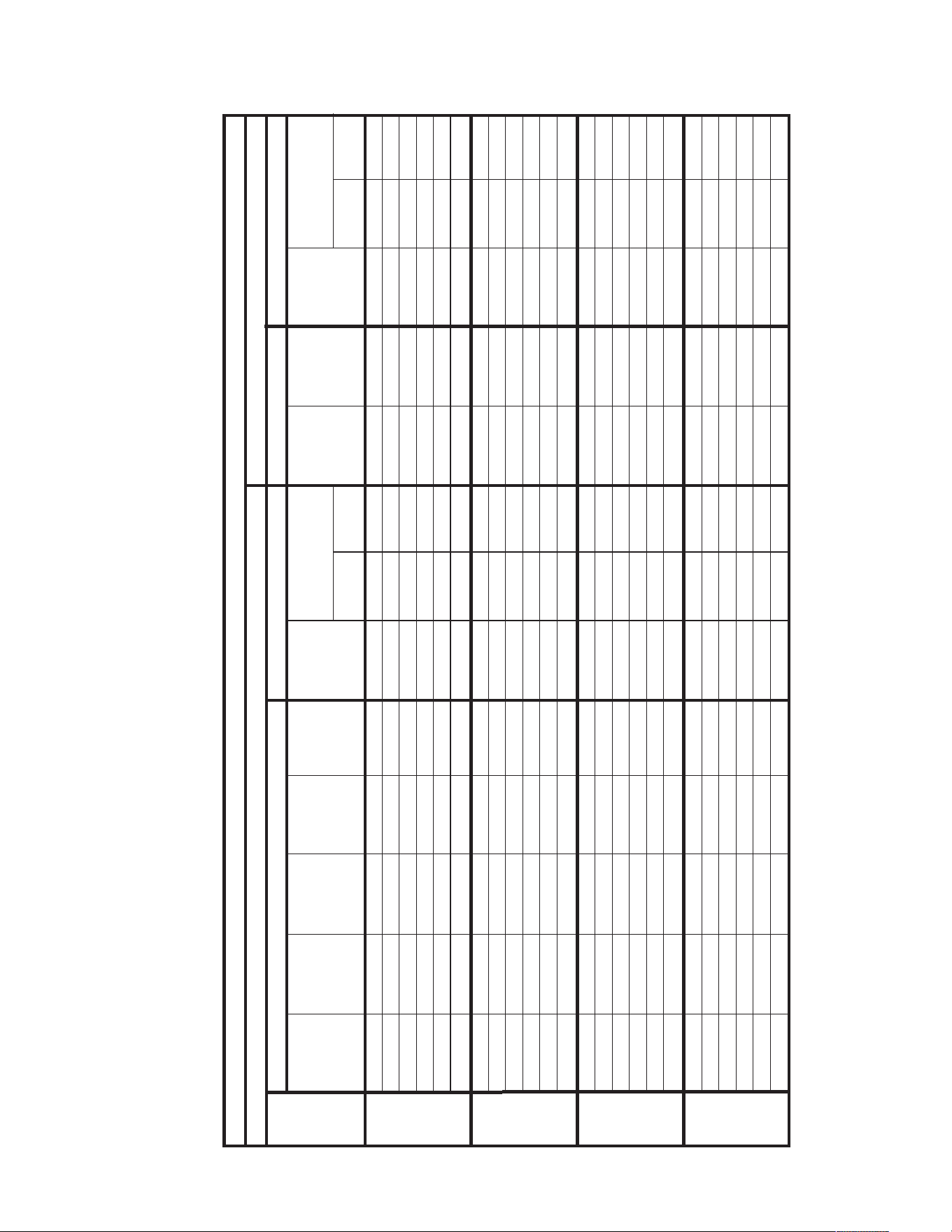
57
AUXILIARY ELECTRIC HEATER KITS CHARACTERISTICS AND APPLICATION – RJNL
No Heat — — — — 11 15/15 — — — 11 15/15 —
A06D 1 5.6 19.1 6.7 20 20/20 — 9 15 11/0 15/15 0/0
A10D 1 9.6 32.75 11.6 26 25/25 — 15 15 11/0 15/15 0/0
A12D 1 11.2 38.21 13.5 28 30/30 — 17 20 11/0 15/15 0/0
A15D 1 14.4 49.13 17.4 33 35/35 — 22 25 11/0 15/15 0/0
A20D 1 19.2 65.5 23.3 41 40/40 — 30 30 11/0 15/15 0/0
No Heat — — — — 11 15/15 — — — 11 15/15 —
A06D 1 5.6 19.1 6.7 20 20/20 — 9 15 11/0 15/15 0/0
A10D 1 9.6 32.75 11.6 26 30/30 — 15 15 11/0 15/15 0/0
A12D 1 11.2 38.21 13.5 28 30/30 — 17 20 11/0 15/15 0/0
A15D 1 14.4 49.13 17.4 33 35/35 — 22 25 11/0 15/15 0/0
A20D 1 19.2 65.5 23.3 41 40/40 — 30 30 11/0 15/15 0/0
No Heat — — — — 13 15/20 — — — 13 15/20 —
A06D 1 5.6 19.1 6.7 22 25/25 — 9 15 13/0 15/20 0/0
A10D 1 9.6 32.75 11.6 28 30/30 — 15 15 13/0 15/20 0/0
A12D 1 11.2 38.21 13.5 30 30/30 — 17 20 13/0 15/20 0/0
A15D 1 14.4 49.13 17.4 35 35/35 — 22 25 13/0 15/20 0/0
A20D 1 19.2 65.5 23.3 43 45/45 — 30 30 13/0 15/20 0/0
480 VOLT, THREE PHASE, 60 HZ, AUXILIARY ELECTRIC HEATER KITS CHARACTERISTICS AND APPLICATION
Single Power Supply For Both Unit And Heater Kit
Separate Power Supply For Both Unit And Heater Kit
Unit
Model
Number
RXJJ-
Heater Kit
Nominal kW
No. of
Sequence
Steps
Rated Heater
kW @
480 V
Heater
KBTU/Hr @
480 V
Heater
Amp. @
480 V
Unit Min. Ckt
Ampacity @
480 V
Min/Max
@ 480 V
Min/Max
@ 480 V
Over Current
Protective Device Size
Min. Ckt.
Ampacity
480V
Max. Fuse
Size
480V
Min. Circuit
Ampacity
480V
Min/Max
@ 480 V
Min/Max
@ 480 V
Over Current
Protective Device Size
RJNL-
A036DK
RJNL-
A042DK
RJNL-
A048DK
RJNL-
A060DK
Heater Kit
Heat Pump
Heater Kit
Heat Pump
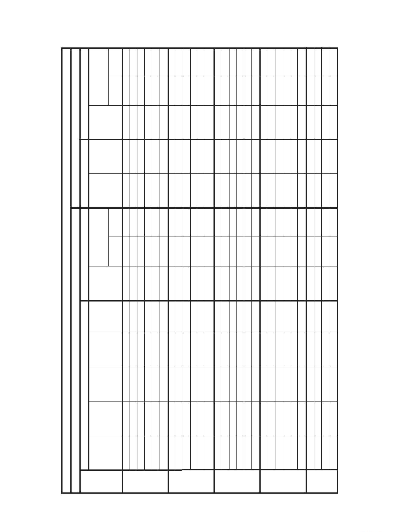
58
AUXILIARY ELECTRIC HEATER KITS CHARACTERISTICS AND APPLICATION – RJNL
No Heat — — — — 10 15/15 — — — 10 15/15 —
A06D 1 5.6 19.1 6.7 19 20/20 — 9 15 10/0 15/15 0/0
A10D 1 9.6 32.75 11.6 25 25/25 — 15 15 10/0 15/15 0/0
A12D 1 11.2 38.21 13.5 27 30/30 — 17 20 10/0 15/15 0/0
A15D 1 14.4 49.13 17.4 32 35/35 — 22 25 10/0 15/15 0/0
A20D 1 19.2 65.5 23.3 40 40/40 — 30 30 10/0 15/15 0/0
No Heat — — — — 10 15/15 — — — 10 15/15 —
A06D 1 5.6 19.1 6.7 19 20/20 — 9 15 10/0 15/15 0/0
A10D 1 9.6 32.75 11.6 25 30/30 — 15 15 10/0 15/15 0/0
A12D 1 11.2 38.21 13.5 27 30/30 — 17 20 10/0 15/15 0/0
A15D 1 14.4 49.13 17.4 32 35/35 — 22 25 10/0 15/15 0/0
A20D 1 19.2 65.5 23.3 40 40/40 — 30 30 10/0 15/15 0/0
No Heat — — — — 11 15/15 — — — 11 15/15 —
A06D 1 5.6 19.1 6.7 20 20/20 — 9 15 11/0 15/15 0/0
A10D 1 9.6 32.75 11.6 26 30/30 — 15 15 11/0 15/15 0/0
A12D 1 11.2 38.21 13.5 28 30/30 — 17 20 11/0 15/15 0/0
A15D 1 14.4 49.13 17.4 33 35/35 — 22 25 11/0 15/15 0/0
A20D 1 19.2 65.5 23.3 41 40/40 — 30 30 11/0 15/15 0/0
No Heat — — — — 13 15/20 — — — 13 15/20 —
A06D 1 5.6 19.1 6.7 22 25/25 — 9 15 13/0 15/20 0/0
A10D 1 9.6 32.75 11.6 28 30/30 — 15 15 13/0 15/20 0/0
A12D 1 11.2 38.21 13.5 30 30/30 — 17 20 13/0 15/20 0/0
A15D 1 14.4 49.13 17.4 35 35/35 — 22 25 13/0 15/20 0/0
A20D 1 19.2 65.5 23.3 43 45/45 — 30 30 13/0 15/20 0/0
480 VOLT, THREE PHASE, 60 HZ, AUXILIARY ELECTRIC HEATER KITS CHARACTERISTICS AND APPLICATION
Single Power Supply For Both Unit And Heater Kit
Separate Power Supply For Both Unit And Heater Kit
Unit
Model
Number
RXJJ-
Heater Kit
Nominal kW
No. of
Sequence
Steps
Rated Heater
kW @
480 V
Heater
KBTU/Hr @
480 V
Heater
Amp. @
480 V
Unit Min. Ckt
Ampacity @
480 V
Min/Max
@ 480 V
Min/Max
@ 480 V
Over Current
Protective Device Size
Min. Ckt.
Ampacity
480V
Max. Fuse
Size
480V
Min. Circuit
Ampacity
480V
Min/Max
@ 480 V
Min/Max
@ 480 V
Over Current
Protective Device Size
RJNL-
A036DL
RJNL-
A042DL
RJNL-
A048DL
RJNL-
A060DL
RJNL-
A072DL
Heater Kit
Heat Pump
Heater Kit
Heat Pump
No Heat — — — — 17 20/25 — — — 17 20/25 —
A15C 1 14.4 49.13 17.4 39 40/40 — 22 25 17/0 20/25 0/0
A20C 1 19.2 65.5 23.3 47 50/50 — 30 30 17/0 20/25 0/0
A24C 1 24 81.88 28.9 54 60/60 — 37 40 17/0 20/25 0/0
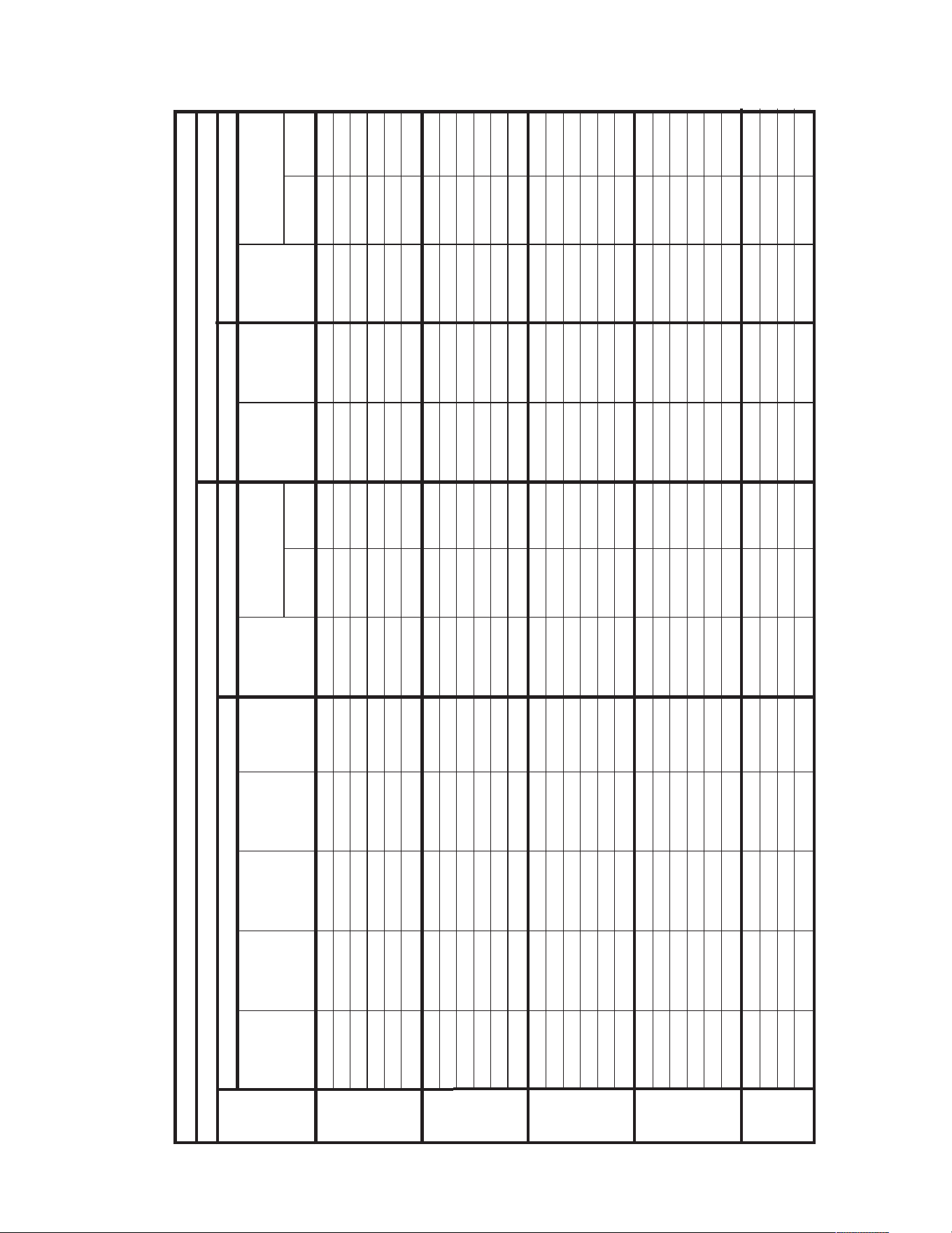
59
AUXILIARY ELECTRIC HEATER KITS CHARACTERISTICS AND APPLICATION – RJNL
No Heat — — — — 10 15/15 — — — 10 15/15 —
A06D 1 5.6 19.1 6.7 19 20/20 — 9 15 10/0 15/15 0/0
A10D 1 9.6 32.75 11.6 25 25/25 — 15 15 10/0 15/15 0/0
A12D 1 11.2 38.21 13.5 27 30/30 — 17 20 10/0 15/15 0/0
A15D 1 14.4 49.13 17.4 32 35/35 — 22 25 10/0 15/15 0/0
A20D 1 19.2 65.5 23.3 40 40/40 — 30 30 10/0 15/15 0/0
No Heat — — — — 11 15/15 — — — 11 15/15 —
A06D 1 5.6 19.1 6.7 20 20/20 — 9 15 11/0 15/15 0/0
A10D 1 9.6 32.75 11.6 26 30/30 — 15 15 11/0 15/15 0/0
A12D 1 11.2 38.21 13.5 28 30/30 — 17 20 11/0 15/15 0/0
A15D 1 14.4 49.13 17.4 33 35/35 — 22 25 11/0 15/15 0/0
A20D 1 19.2 65.5 23.3 41 40/40 — 30 30 11/0 15/15 0/0
No Heat — — — — 11 15/15 — — — 11 15/15 —
A06D 1 5.6 19.1 6.7 20 20/20 — 9 15 11/0 15/15 0/0
A10D 1 9.6 32.75 11.6 26 30/30 — 15 15 11/0 15/15 0/0
A12D 1 11.2 38.21 13.5 28 30/30 — 17 20 11/0 15/15 0/0
A15D 1 14.4 49.13 17.4 33 35/35 — 22 25 11/0 15/15 0/0
A20D 1 19.2 65.5 23.3 41 45/45 — 30 30 11/0 15/15 0/0
No Heat — — — — 14 20/20 — — — 14 20/20 —
A06D 1 5.6 19.1 6.7 23 25/25 — 9 15 14/0 20/20 0/0
A10D 1 9.6 32.75 11.6 29 30/30 — 15 15 14/0 20/20 0/0
A12D 1 11.2 38.21 13.5 31 35/35 — 17 20 14/0 20/20 0/0
A15D 1 14.4 49.13 17.4 36 40/40 — 22 25 14/0 20/20 0/0
A20D 1 19.2 65.5 23.3 44 45/45 — 30 30 14/0 20/20 0/0
480 VOLT, THREE PHASE, 60 HZ, AUXILIARY ELECTRIC HEATER KITS CHARACTERISTICS AND APPLICATION
Single Power Supply For Both Unit And Heater Kit
Separate Power Supply For Both Unit And Heater Kit
Unit
Model
Number
RXJJ-
Heater Kit
Nominal kW
No. of
Sequence
Steps
Rated Heater
kW @
480 V
Heater
KBTU/Hr @
480 V
Heater
Amp. @
480 V
Unit Min. Ckt
Ampacity @
480 V
Min/Max
@ 480 V
Min/Max
@ 480 V
Over Current
Protective Device Size
Min. Ckt.
Ampacity
480V
Max. Fuse
Size
480V
Min. Circuit
Ampacity
480V
Min/Max
@ 480 V
Min/Max
@ 480 V
Over Current
Protective Device Size
RJNL-
A036DM
RJNL-
A042DM
RJNL-
A048DM
RJNL-
A060DM
RJNL-
A072DM
Heater Kit
Heat Pump
Heater Kit
Heat Pump
No Heat — — — — 17 20/25 — — — 17 20/25 —
A15D 1 14.4 49.13 17.4 39 40/40 — 22 25 17/0 20/25 0/0
A20D 1 19.2 65.5 23.3 47 50/50 — 30 30 17/0 20/25 0/0
A24D 1 24 81.88 28.9 54 60/60 — 37 40 17/0 20/25 0/0
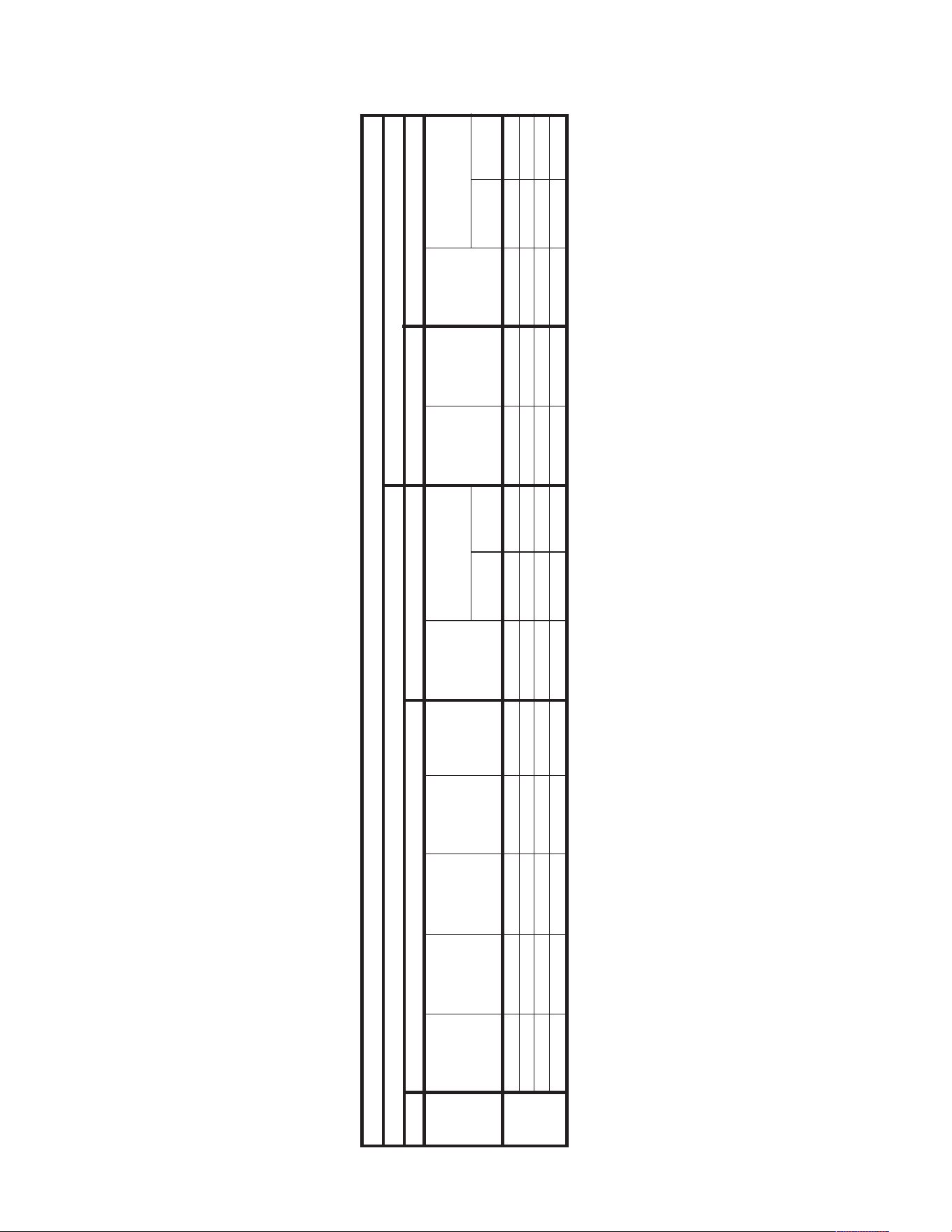
60
AUXILIARY ELECTRIC HEATER KITS CHARACTERISTICS AND APPLICATION
600 VOLT, THREE PHASE, 60 HZ, AUXILIARY ELECTRIC HEATER KITS CHARACTERISTICS AND APPLICATION
Single Power Supply For Both Unit And Heater Kit
Separate Power Supply For Both Unit And Heater Kit
Unit
Model
Number
RXJJ-
Heater Kit
Nominal kW
No. of
Sequence
Steps
Rated Heater
kW @
600 V
Heater
KBTU/Hr @
600 V
Heater
Amp. @
600 V
Unit Min. Ckt
Ampacity @
600V
Min/Max
@ 600 V
Min/Max
@600 V
Over Current
Protective Device Size
Min. Ckt.
Ampacity
600V
Max. Fuse
Size
600V
Min. Circuit
Ampacity
600V
Min/Max
@ 60 V
Min/Max
@ 600 V
Over Current
Protective Device Size
No Heat — — — — 14 15/20 — — — 14 15/20 —
A15Y 1 14.4 49.13 13.9 32 35/35 — 18 20 14/0 15/20 0/0
A20Y 1 19.2 65.5 18.8 38 40/40 — 24 25 14/0 15/20 0/0
A24Y 1 24 81.88 23.1 43 45/45 — 29 30 14/0 15/20 0/0
RJNL-
A072YL
Heater Kit
Heat Pump
Heater Kit
Heat Pump
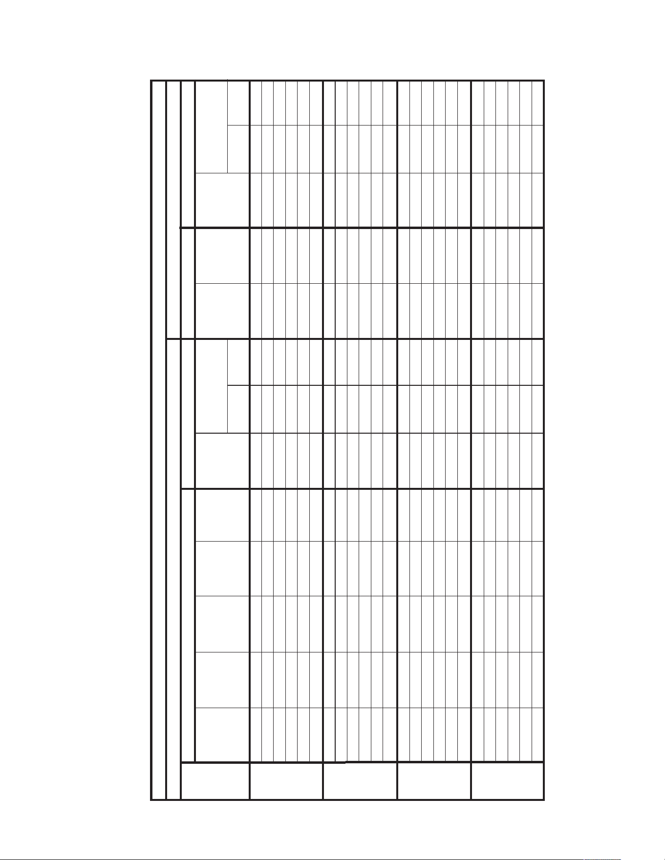
61
AUXILIARY ELECTRIC HEATER KITS CHARACTERISTICS AND APPLICATION – RJPL
No Heat — — — — 24/24 30/40 30/40 — — 24/24 30/40 30/40
A06J 1 4.2/5.6 14.33/19.1 20.2/23.3 50/54 50/60 60/60 26/30 30/30 24/24 30/40 30/40
A10J 1 7.2/9.6 24.56/32.75 34.6/40 68/74 70/70 80/80 44/50 45/50 24/24 30/40 30/40
A12J 1 8.4/11.2 28.66/38.21 40.4/46.7 75/83 80/80 90/90 51/59 60/60 24/24 30/40 30/40
A15J 1 10.8/14.4 36.84/49.13 51.9/60 89/99 90/90 100/100 65/75 70/80 24/24 30/40 30/40
A20J 1 14.4/19.2 49.13/65.5 69.3/80 111/124 125/125 125/125 87/100 90/100 24/24 30/40 30/40
No Heat — — — — 26/26 35/40 35/40 — — 26/26 35/40 35/40
A06J 1 4.2/5.6 14.33/19.1 20.2/23.3 52/56 60/60 60/60 26/30 30/30 26/26 35/40 35/40
A10J 1 7.2/9.6 24.56/32.75 34.6/40 70/76 70/70 80/80 44/50 45/50 26/26 35/40 35/40
A12J 1 8.4/11.2 28.66/38.21 40.4/46.7 77/85 80/80 90/90 51/59 60/60 26/26 35/40 35/40
A15J 1 10.8/14.4 36.84/49.13 51.9/60 91/101 100/100 110/110 65/75 70/80 26/26 35/40 35/40
A20J 1 14.4/19.2 49.13/65.5 69.3/80 113/126 125/125 150/150 87/100 90/100 26/26 35/40 35/40
No Heat — — — — 31/31 40/50 40/50 — — 31/31 40/50 40/50
A06J 1 4.2/5.6 14.33/19.1 20.2/23.3 57/61 60/70 70/70 26/30 30/30 31/31 40/50 40/50
A10J 1 7.2/9.6 24.56/32.75 34.6/40 75/81 80/80 90/90 44/50 45/50 31/31 40/50 40/50
A12J 1 8.4/11.2 28.66/38.21 40.4/46.7 82/90 90/90 90/90 51/59 60/60 31/31 40/50 40/50
A15J 1 10.8/14.4 36.84/49.13 51.9/60 96/106 100/100 110/110 65/75 70/80 31/31 40/50 40/50
A20J 1 14.4/19.2 49.13/65.5 69.3/80 118/131 125/125 150/150 87/100 90/100 31/31 40/50 40/50
No Heat — — — — 39/39 45/60 45/60 — — 39/39 45/60 45/60
A06J 1 4.2/5.6 14.33/19.1 20.2/23.3 65/69 70/80 70/80 26/30 30/30 39/39 45/60 45/60
A10J 1 7.2/9.6 24.56/32.75 34.6/40 83/89 90/90 90/100 44/50 45/50 39/39 45/60 45/60
A12J 1 8.4/11.2 28.66/38.21 40.4/46.7 90/98 90/100 100/110 51/59 60/60 39/39 45/60 45/60
A15J 1 10.8/14.4 36.84/49.13 51.9/60 104/114 110/110 125/125 65/75 70/80 39/39 45/60 45/60
A20J 1 14.4/19.2 49.13/65.5 69.3/80 126/139 150/150 150/150 87/100 90/100 39/39 45/60 45/60
208-240 VOLT, THREE PHASE, 60 HZ, AUXILIARY ELECTRIC HEATER KITS CHARACTERISTICS AND APPLICATION
Single Power Supply For Both Unit And Heater Kit
Separate Power Supply For Both Unit And Heater Kit
Unit
Model
Number
RXJJ-
Heater Kit
Nominal kW
No. of
Sequence
Steps
Rated Heater
kW @
208/240 V
Heater
KBTU/Hr @
208/240 V
Heater
Amp. @
208-240 V
Unit Min. Ckt
Ampacity @
208-240V
Min/Max
@ 208 V
Min/Max
@240 V
Over Current
Protective Device Size
Min. Ckt.
Ampacity
208/240V
Max. Fuse
Size
208/240V
Min. Circuit
Ampacity
208/240V
Min/Max
@ 208 V
Min/Max
@ 240 V
Over Current
Protective Device Size
RJPL-
A036JK
RJPL-
A042JK
RJPL-
A048JK
RJPL-
A060JK
Heater Kit
Heat Pump
Heater Kit
Heat Pump

62
AUXILIARY ELECTRIC HEATER KITS CHARACTERISTICS AND APPLICATION – RJPL
No Heat — — — — 17/17 20/25 20/25 — — 17/17 20/25 20/25
A06C 1 4.2/5.6 14.33/19.1 11.7/13.5 32/34 35/35 35/35 15/17 15/20 17/17 20/25 20/25
A10C 1 7.2/9.6 24.56/32.75 20/23.1 42/46 45/45 50/50 25/29 25/30 17/17 20/25 20/25
A12C 1 8.4/11.2 28.66/38.21 23.4/27 47/51 50/50 60/60 30/34 30/35 17/17 20/25 20/25
A15C 1 10.8/14.4 36.84/49.13 30.1/34.7 55/61 60/60 70/70 38/44 40/45 17/17 20/25 20/25
A20C 1 14.4/19.2 49.13/65.5 40/46.3 67/75 70/70 80/80 50/58 50/60 17/17 20/25 20/25
No Heat — — — — 21/21 25/30 25/30 — — 21/21 25/30 25/30
A06C 1 4.2/5.6 14.33/19.1 11.7/13.5 36/38 40/45 40/45 15/17 15/20 21/21 25/30 25/30
A10C 1 7.2/9.6 24.56/32.75 20/23.1 46/50 50/50 50/50 25/29 25/30 21/21 25/30 25/30
A12C 1 8.4/11.2 28.66/38.21 23.4/27 51/55 60/60 60/60 30/34 30/35 21/21 25/30 25/30
A15C 1 10.8/14.4 36.84/49.13 30.1/34.7 59/65 60/60 70/70 38/44 40/45 21/21 25/30 25/30
A20C 1 14.4/19.2 49.13/65.5 40/46.3 71/79 80/80 80/80 50/58 50/60 21/21 25/30 25/30
No Heat — — — — 21/21 25/30 25/30 — — 21/21 25/30 25/30
A06C 1 4.2/5.6 14.33/19.1 11.7/13.5 36/38 40/45 40/45 15/17 15/20 21/21 25/30 25/30
A10C 1 7.2/9.6 24.56/32.75 20/23.1 46/50 50/50 60/60 25/29 25/30 21/21 25/30 25/30
A12C 1 8.4/11.2 28.66/38.21 23.4/27 51/55 60/60 60/60 30/34 30/35 21/21 25/30 25/30
A15C 1 10.8/14.4 36.84/49.13 30.1/34.7 59/65 60/60 70/70 38/44 40/45 21/21 25/30 25/30
A20C 1 14.4/19.2 49.13/65.5 40/46.3 71/79 80/80 80/80 50/58 50/60 21/21 25/30 25/30
No Heat — — — — 25/25 30/40 30/40 — — 25/25 30/40 30/40
A06C 1 4.2/5.6 14.33/19.1 11.7/13.5 40/42 45/50 45/50 15/17 15/20 25/25 30/40 30/40
A10C 1 7.2/9.6 24.56/32.75 20/23.1 50/54 60/60 60/60 25/29 25/30 25/25 30/40 30/40
A12C 1 8.4/11.2 28.66/38.21 23.4/27 55/59 60/60 60/60 30/34 30/35 25/25 30/40 30/40
A15C 1 10.8/14.4 36.84/49.13 30.1/34.7 63/69 70/70 70/70 38/44 40/45 25/25 30/40 30/40
A20C 1 14.4/19.2 49.13/65.5 40/46.3 75/83 80/80 90/90 50/58 50/60 25/25 30/40 30/40
208-240 VOLT, THREE PHASE, 60 HZ, AUXILIARY ELECTRIC HEATER KITS CHARACTERISTICS AND APPLICATION
Single Power Supply For Both Unit And Heater Kit
Separate Power Supply For Both Unit And Heater Kit
Unit
Model
Number
RXJJ-
Heater Kit
Nominal kW
No. of
Sequence
Steps
Rated Heater
kW @
208/240 V
Heater
KBTU/Hr @
208/240 V
Heater
Amp. @
208-240 V
Unit Min. Ckt
Ampacity @
208-240V
Min/Max
@ 208 V
Min/Max
@240 V
Over Current
Protective Device Size
Min. Ckt.
Ampacity
208/240V
Max. Fuse
Size
208/240V
Min. Circuit
Ampacity
208/240V
Min/Max
@ 208 V
Min/Max
@ 240 V
Over Current
Protective Device Size
RJPL-
A036CK
RJPL-
A042CK
RJPL-
A048CK
RJPL-
A060CK
Heater Kit
Heat Pump
Heater Kit
Heat Pump
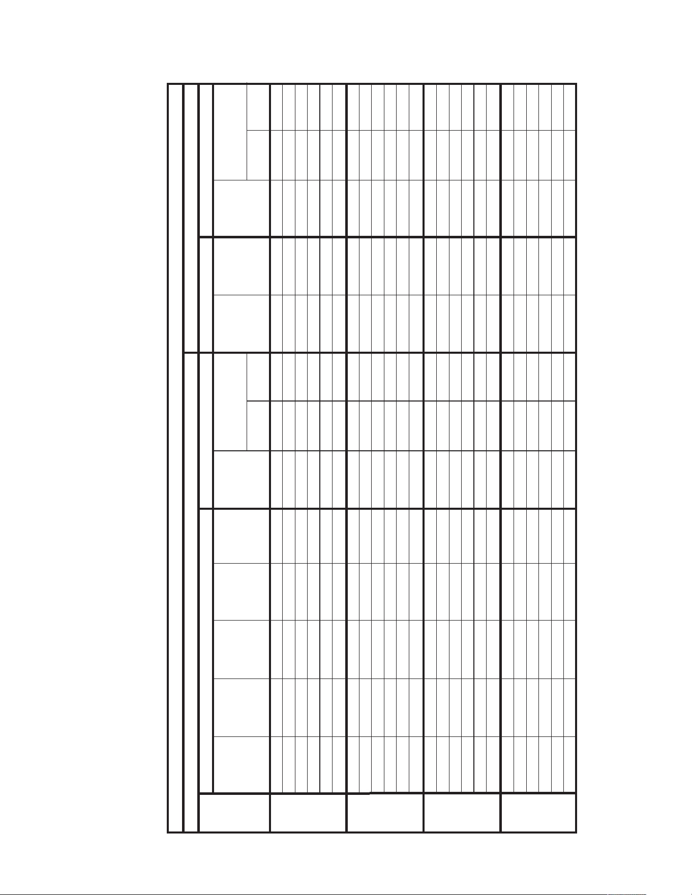
63
AUXILIARY ELECTRIC HEATER KITS CHARACTERISTICS AND APPLICATION – RJPL
No Heat — — — — 18/18 20/25 20/25 — — 18/18 20/25 20/25
A06C 1 4.2/5.6 14.33/19.1 11.7/13.5 33/35 35/35 40/40 15/17 15/20 18/18 20/25 20/25
A10C 1 7.2/9.6 24.56/32.75 20/23.1 43/47 45/45 50/50 25/29 25/30 18/18 20/25 20/25
A12C 1 8.4/11.2 28.66/38.21 23.4/27 48/52 50/50 60/60 30/34 30/35 18/18 20/25 20/25
A15C 1 10.8/14.4 36.84/49.13 30.1/34.7 56/62 60/60 70/70 38/44 40/45 18/18 20/25 20/25
A20C 1 14.4/19.2 49.13/65.5 40/46.3 68/76 70/70 80/80 50/58 50/60 18/18 20/25 20/25
No Heat — — — — 22/22 25/30 25/30 — — 22/22 25/30 25/30
A06C 1 4.2/5.6 14.33/19.1 11.7/13.5 37/39 40/45 40/45 15/17 15/20 22/22 25/30 25/30
A10C 1 7.2/9.6 24.56/32.75 20/23.1 47/51 50/50 60/60 25/29 25/30 22/22 25/30 25/30
A12C 1 8.4/11.2 28.66/38.21 23.4/27 52/56 60/60 60/60 30/34 30/35 22/22 25/30 25/30
A15C 1 10.8/14.4 36.84/49.13 30.1/34.7 60/66 60/60 70/70 38/44 40/45 22/22 25/30 25/30
A20C 1 14.4/19.2 49.13/65.5 40/46.3 72/80 80/80 90/90 50/58 50/60 22/22 25/30 25/30
No Heat — — — — 22/22 25/35 25/35 — — 22/22 25/35 25/35
A06C 1 4.2/5.6 14.33/19.1 11.7/13.5 37/39 40/45 40/45 15/17 15/20 22/22 25/35 25/35
A10C 1 7.2/9.6 24.56/32.75 20/23.1 47/51 50/50 60/60 25/29 25/30 22/22 25/35 25/35
A12C 1 8.4/11.2 28.66/38.21 23.4/27 52/56 60/60 60/60 30/34 30/35 22/22 25/35 25/35
A15C 1 10.8/14.4 36.84/49.13 30.1/34.7 60/66 70/70 70/70 38/44 40/45 22/22 25/35 25/35
A20C 1 14.4/19.2 49.13/65.5 40/46.3 72/80 80/80 90/90 50/58 50/60 22/22 25/35 25/35
No Heat — — — — 26/26 30/40 30/40 — — 26/26 30/40 30/40
A06C 1 4.2/5.6 14.33/19.1 11.7/13.5 41/43 45/50 45/50 15/17 15/20 26/26 30/40 30/40
A10C 1 7.2/9.6 24.56/32.75 20/23.1 51/55 60/60 60/60 25/29 25/30 26/26 30/40 30/40
A12C 1 8.4/11.2 28.66/38.21 23.4/27 56/60 60/60 70/70 30/34 30/35 26/26 30/40 30/40
A15C 1 10.8/14.4 36.84/49.13 30.1/34.7 64/70 70/70 80/80 38/44 40/45 26/26 30/40 30/40
A20C 1 14.4/19.2 49.13/65.5 40/46.3 76/84 80/80 90/90 50/58 50/60 26/26 30/40 30/40
208-240 VOLT, THREE PHASE, 60 HZ, AUXILIARY ELECTRIC HEATER KITS CHARACTERISTICS AND APPLICATION
Single Power Supply For Both Unit And Heater Kit
Separate Power Supply For Both Unit And Heater Kit
Unit
Model
Number
RXJJ-
Heater Kit
Nominal kW
No. of
Sequence
Steps
Rated Heater
kW @
208/240 V
Heater
KBTU/Hr @
208/240 V
Heater
Amp. @
208-240 V
Unit Min. Ckt
Ampacity @
208-240V
Min/Max
@ 208 V
Min/Max
@240 V
Over Current
Protective Device Size
Min. Ckt.
Ampacity
208/240V
Max. Fuse
Size
208/240V
Min. Circuit
Ampacity
208/240V
Min/Max
@ 208 V
Min/Max
@ 240 V
Over Current
Protective Device Size
RJPL-
A036CL
RJPL-
A042CL
RJPL-
A048CL
RJPL-
A060CL
Heater Kit
Heat Pump
Heater Kit
Heat Pump
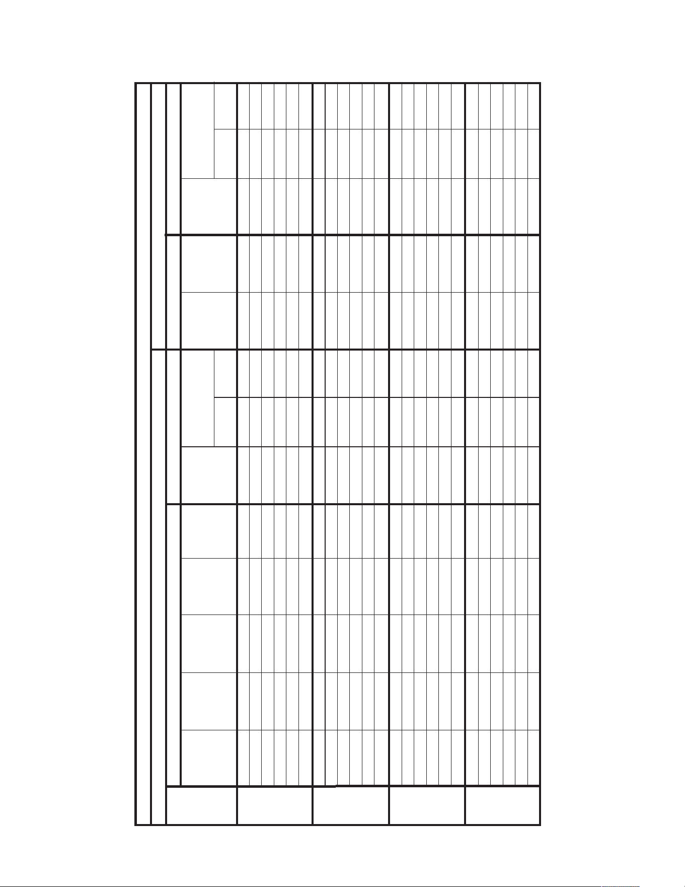
64
AUXILIARY ELECTRIC HEATER KITS CHARACTERISTICS AND APPLICATION – RJPL
No Heat — — — — 18/18 25/25 25/25 — — 18/18 25/25 25/25
A06C 1 4.2/5.6 14.33/19.1 11.7/13.5 33/35 35/35 40/40 15/17 15/20 18/18 25/25 25/25
A10C 1 7.2/9.6 24.56/32.75 20/23.1 43/47 45/45 50/50 25/29 25/30 18/18 25/25 25/25
A12C 1 8.4/11.2 28.66/38.21 23.4/27 48/52 50/50 60/60 30/34 30/35 18/18 25/25 25/25
A15C 1 10.8/14.4 36.84/49.13 30.1/34.7 56/62 60/60 70/70 38/44 40/45 18/18 25/25 25/25
A20C 1 14.4/19.2 49.13/65.5 40/46.3 68/76 70/70 80/80 50/58 50/60 18/18 25/25 25/25
No Heat — — — — 22/22 30/35 30/35 — — 22/22 30/35 30/35
A06C 1 4.2/5.6 14.33/19.1 11.7/13.5 37/39 40/45 40/45 15/17 15/20 22/22 30/35 30/35
A10C 1 7.2/9.6 24.56/32.75 20/23.1 47/51 50/50 60/60 25/29 25/30 22/22 30/35 30/35
A12C 1 8.4/11.2 28.66/38.21 23.4/27 52/56 60/60 60/60 30/34 30/35 22/22 30/35 30/35
A15C 1 10.8/14.4 36.84/49.13 30.1/34.7 60/66 70/70 70/70 38/44 40/45 22/22 30/35 30/35
A20C 1 14.4/19.2 49.13/65.5 40/46.3 72/80 80/80 90/90 50/58 50/60 22/22 30/35 30/35
No Heat — — — — 23/23 30/35 30/35 — — 23/23 30/35 30/35
A06C 1 4.2/5.6 14.33/19.1 11.7/13.5 38/40 40/45 45/45 15/17 15/20 23/23 30/35 30/35
A10C 1 7.2/9.6 24.56/32.75 20/23.1 48/52 50/50 60/60 25/29 25/30 23/23 30/35 30/35
A12C 1 8.4/11.2 28.66/38.21 23.4/27 53/57 60/60 60/60 30/34 30/35 23/23 30/35 30/35
A15C 1 10.8/14.4 36.84/49.13 30.1/34.7 61/67 70/70 70/70 38/44 40/45 23/23 30/35 30/35
A20C 1 14.4/19.2 49.13/65.5 40/46.3 73/81 80/80 90/90 50/58 50/60 23/23 30/35 30/35
No Heat — — — — 26/26 30/40 30/40 — — 26/26 30/40 30/40
A06C 1 4.2/5.6 14.33/19.1 11.7/13.5 41/43 45/50 45/50 15/17 15/20 26/26 30/40 30/40
A10C 1 7.2/9.6 24.56/32.75 20/23.1 51/55 60/60 60/60 25/29 25/30 26/26 30/40 30/40
A12C 1 8.4/11.2 28.66/38.21 23.4/27 56/60 60/60 70/70 30/34 30/35 26/26 30/40 30/40
A15C 1 10.8/14.4 36.84/49.13 30.1/34.7 64/70 70/70 80/80 38/44 40/45 26/26 30/40 30/40
A20C 1 14.4/19.2 49.13/65.5 40/46.3 76/84 80/80 90/90 50/58 50/60 26/26 30/40 30/40
208-240 VOLT, THREE PHASE, 60 HZ, AUXILIARY ELECTRIC HEATER KITS CHARACTERISTICS AND APPLICATION
Single Power Supply For Both Unit And Heater Kit
Separate Power Supply For Both Unit And Heater Kit
Unit
Model
Number
RXJJ-
Heater Kit
Nominal kW
No. of
Sequence
Steps
Rated Heater
kW @
208/240 V
Heater
KBTU/Hr @
208/240 V
Heater
Amp. @
208-240 V
Unit Min. Ckt
Ampacity @
208-240V
Min/Max
@ 208 V
Min/Max
@240 V
Over Current
Protective Device Size
Min. Ckt.
Ampacity
208/240V
Max. Fuse
Size
208/240V
Min. Circuit
Ampacity
208/240V
Min/Max
@ 208 V
Min/Max
@ 240 V
Over Current
Protective Device Size
RJPL-
A036CM
RJPL-
A042CM
RJPL-
A048CM
RJPL-
A060CM
Heater Kit
Heat Pump
Heater Kit
Heat Pump

65
AUXILIARY ELECTRIC HEATER KITS CHARACTERISTICS AND APPLICATION – RJPL
No Heat — — — — 10 15/15 — — — 10 15/15 —
A06D 1 5.6 19.1 6.7 19 20/20 — 9 15 10/0 15/15 0/0
A10D 1 9.6 32.75 11.6 25 25/25 — 15 15 10/0 15/15 0/0
A12D 1 11.2 38.21 13.5 27 30/30 — 17 20 10/0 15/15 0/0
A15D 1 14.4 49.13 17.4 32 35/35 — 22 25 10/0 15/15 0/0
A20D 1 19.2 65.5 23.3 40 40/40 — 30 30 10/0 15/15 0/0
No Heat — — — — 13 15/20 — — — 13 15/20 —
A06D 1 5.6 19.1 6.7 22 25/25 — 9 15 13/0 15/20 0/0
A10D 1 9.6 32.75 11.6 28 30/30 — 15 15 13/0 15/20 0/0
A12D 1 11.2 38.21 13.5 30 30/30 — 17 20 13/0 15/20 0/0
A15D 1 14.4 49.13 17.4 35 35/35 — 22 25 13/0 15/20 0/0
A20D 1 19.2 65.5 23.3 43 45/45 — 30 30 13/0 15/20 0/0
480 VOLT, THREE PHASE, 60 HZ, AUXILIARY ELECTRIC HEATER KITS CHARACTERISTICS AND APPLICATION
Single Power Supply For Both Unit And Heater Kit
Separate Power Supply For Both Unit And Heater Kit
Unit
Model
Number
RXJJ-
Heater Kit
Nominal kW
No. of
Sequence
Steps
Rated Heater
kW @
480 V
Heater
KBTU/Hr @
480 V
Heater
Amp. @
480 V
Unit Min. Ckt
Ampacity @
480 V
Min/Max
@ 480 V
Min/Max
@ 480 V
Over Current
Protective Device Size
Min. Ckt.
Ampacity
480V
Max. Fuse
Size
480V
Min. Circuit
Ampacity
480V
Min/Max
@ 480 V
Min/Max
@ 480 V
Over Current
Protective Device Size
RJPL-
A036DK
RJPL-
A042DK
RJPL-
A048DK
RJPL-
A060DK
Heater Kit
Heat Pump
Heater Kit
Heat Pump
66
AUXILIARY ELECTRIC HEATER KITS CHARACTERISTICS AND APPLICATION – RJPL
No Heat — — — — 10 15/15 — — — 10 15/15 —
A06D 1 5.6 19.1 6.7 19 20/20 — 9 15 10/0 15/15 0/0
A10D 1 9.6 32.75 11.6 25 25/25 — 15 15 10/0 15/15 0/0
A12D 1 11.2 38.21 13.5 27 30/30 — 17 20 10/0 15/15 0/0
A15D 1 14.4 49.13 17.4 32 35/35 — 22 25 10/0 15/15 0/0
A20D 1 19.2 65.5 23.3 40 40/40 — 30 30 10/0 15/15 0/0
No Heat — — — — 10 15/15 — — — 10 15/15 —
A06D 1 5.6 19.1 6.7 19 20/20 — 9 15 10/0 15/15 0/0
A10D 1 9.6 32.75 11.6 25 30/30 — 15 15 10/0 15/15 0/0
A12D 1 11.2 38.21 13.5 27 30/30 — 17 20 10/0 15/15 0/0
A15D 1 14.4 49.13 17.4 32 35/35 — 22 25 10/0 15/15 0/0
A20D 1 19.2 65.5 23.3 40 40/40 — 30 30 10/0 15/15 0/0
No Heat — — — — 11 15/15 — — — 11 15/15 —
A06D 1 5.6 19.1 6.7 20 20/20 — 9 15 11/0 15/15 0/0
A10D 1 9.6 32.75 11.6 26 30/30 — 15 15 11/0 15/15 0/0
A12D 1 11.2 38.21 13.5 28 30/30 — 17 20 11/0 15/15 0/0
A15D 1 14.4 49.13 17.4 33 35/35 — 22 25 11/0 15/15 0/0
A20D 1 19.2 65.5 23.3 41 40/40 — 30 30 11/0 15/15 0/0
No Heat — — — — 13 15/20 — — — 13 15/20 —
A06D 1 5.6 19.1 6.7 22 25/25 — 9 15 13/0 15/20 0/0
A10D 1 9.6 32.75 11.6 28 30/30 — 15 15 13/0 15/20 0/0
A12D 1 11.2 38.21 13.5 30 30/30 — 17 20 13/0 15/20 0/0
A15D 1 14.4 49.13 17.4 35 35/35 — 22 25 13/0 15/20 0/0
A20D 1 19.2 65.5 23.3 43 45/45 — 30 30 13/0 15/20 0/0
480 VOLT, THREE PHASE, 60 HZ, AUXILIARY ELECTRIC HEATER KITS CHARACTERISTICS AND APPLICATION
Single Power Supply For Both Unit And Heater Kit
Separate Power Supply For Both Unit And Heater Kit
Unit
Model
Number
RXJJ-
Heater Kit
Nominal kW
No. of
Sequence
Steps
Rated Heater
kW @
480 V
Heater
KBTU/Hr @
480 V
Heater
Amp. @
480 V
Unit Min. Ckt
Ampacity @
480 V
Min/Max
@ 480 V
Min/Max
@ 480 V
Over Current
Protective Device Size
Min. Ckt.
Ampacity
480V
Max. Fuse
Size
480V
Min. Circuit
Ampacity
480V
Min/Max
@ 480 V
Min/Max
@ 480 V
Over Current
Protective Device Size
RJPL-
A036DL
RJPL-
A042DL
RJPL-
A048DL
RJPL-
A060DL
Heater Kit
Heat Pump
Heater Kit
Heat Pump
67
AUXILIARY ELECTRIC HEATER KITS CHARACTERISTICS AND APPLICATION – RJPL
No Heat — — — — 10 15/15 — — — 10 15/15 —
A06D 1 5.6 19.1 6.7 19 20/20 — 9 15 10/0 15/15 0/0
A10D 1 9.6 32.75 11.6 25 25/25 — 15 15 10/0 15/15 0/0
A12D 1 11.2 38.21 13.5 27 30/30 — 17 20 10/0 15/15 0/0
A15D 1 14.4 49.13 17.4 32 35/35 — 22 25 10/0 15/15 0/0
A20D 1 19.2 65.5 23.3 40 40/40 — 30 30 10/0 15/15 0/0
No Heat — — — — 11 15/15 — — — 11 15/15 —
A06D 1 5.6 19.1 6.7 20 20/20 — 9 15 11/0 15/15 0/0
A10D 1 9.6 32.75 11.6 26 30/30 — 15 15 11/0 15/15 0/0
A12D 1 11.2 38.21 13.5 28 30/30 — 17 20 11/0 15/15 0/0
A15D 1 14.4 49.13 17.4 33 35/35 — 22 25 11/0 15/15 0/0
A20D 1 19.2 65.5 23.3 41 40/40 — 30 30 11/0 15/15 0/0
No Heat — — — — 13 15/20 — — — 13 15/20 —
A06D 1 5.6 19.1 6.7 22 25/25 — 9 15 13/0 15/20 0/0
A10D 1 9.6 32.75 11.6 28 30/30 — 15 15 13/0 15/20 0/0
A12D 1 11.2 38.21 13.5 30 30/30 — 17 20 13/0 15/20 0/0
A15D 1 14.4 49.13 17.4 35 35/35 — 22 25 13/0 15/20 0/0
A20D 1 19.2 65.5 23.3 43 45/45 — 30 30 13/0 15/20 0/0
480 VOLT, THREE PHASE, 60 HZ, AUXILIARY ELECTRIC HEATER KITS CHARACTERISTICS AND APPLICATION
Single Power Supply For Both Unit And Heater Kit
Separate Power Supply For Both Unit And Heater Kit
Unit
Model
Number
RXJJ-
Heater Kit
Nominal kW
No. of
Sequence
Steps
Rated Heater
kW @
480 V
Heater
KBTU/Hr @
480 V
Heater
Amp. @
480 V
Unit Min. Ckt
Ampacity @
480 V
Min/Max
@ 480 V
Min/Max
@ 480 V
Over Current
Protective Device Size
Min. Ckt.
Ampacity
480V
Max. Fuse
Size
480V
Min. Circuit
Ampacity
480V
Min/Max
@ 480 V
Min/Max
@ 480 V
Over Current
Protective Device Size
RJPL-
A036DM
RJPL-
A042DM
RJPL-
A048DM
RJPL-
A060DM
Heater Kit
Heat Pump
Heater Kit
Heat Pump
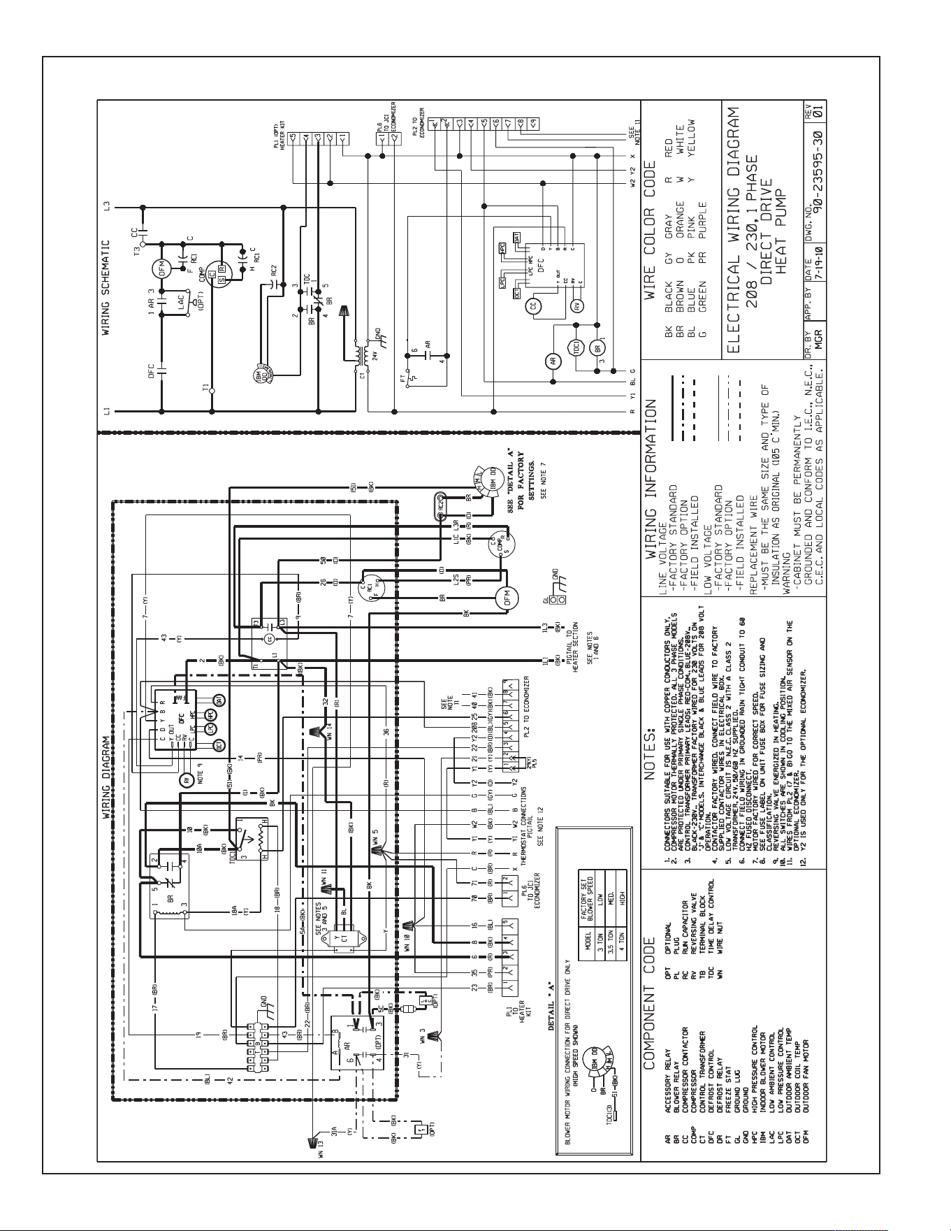
68
FIGURE 19
W
IRING DIAGRAM
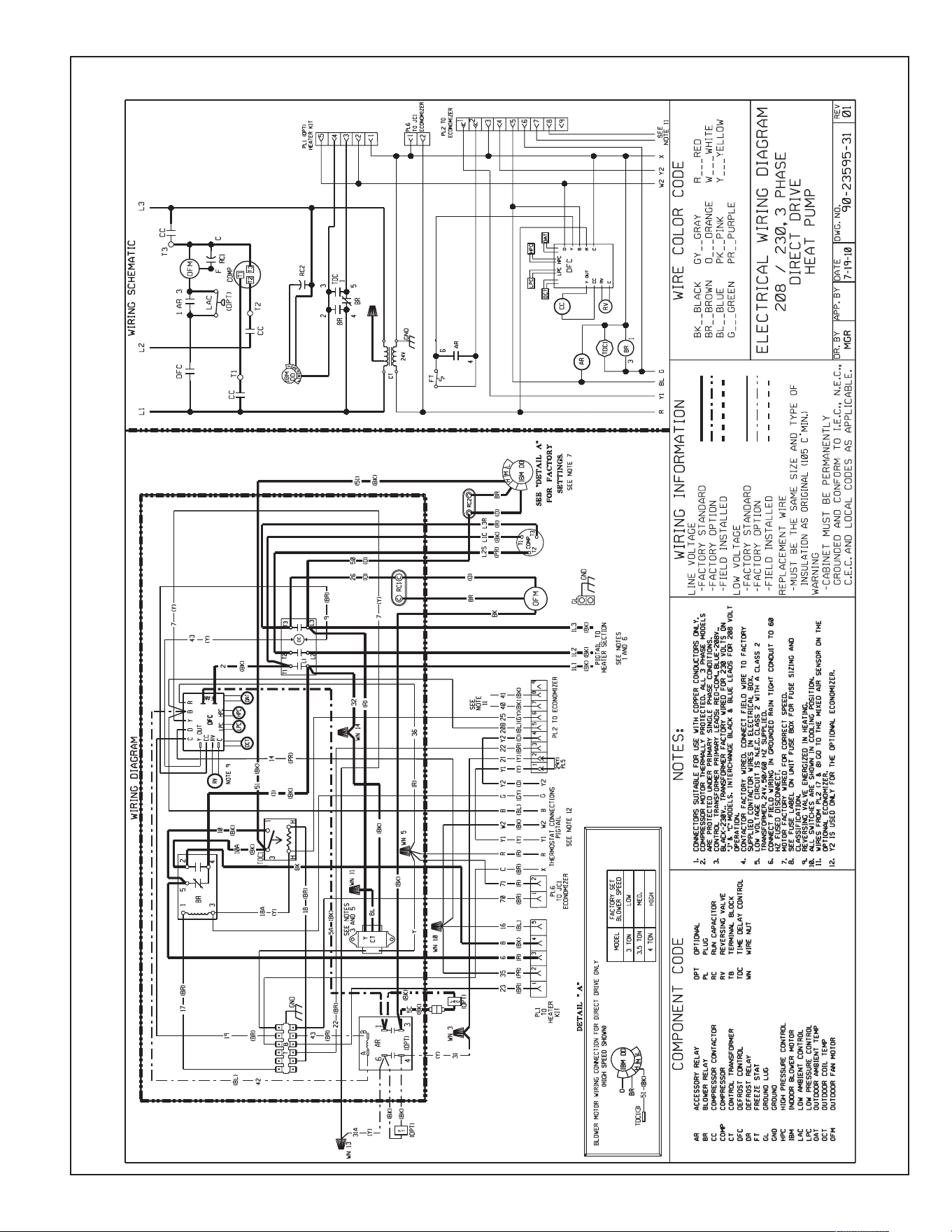
69
FIGURE 20
W
IRING DIAGRAM
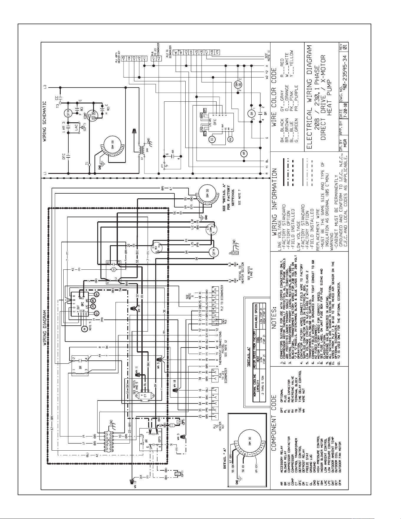
70
FIGURE 21
W
IRING DIAGRAM
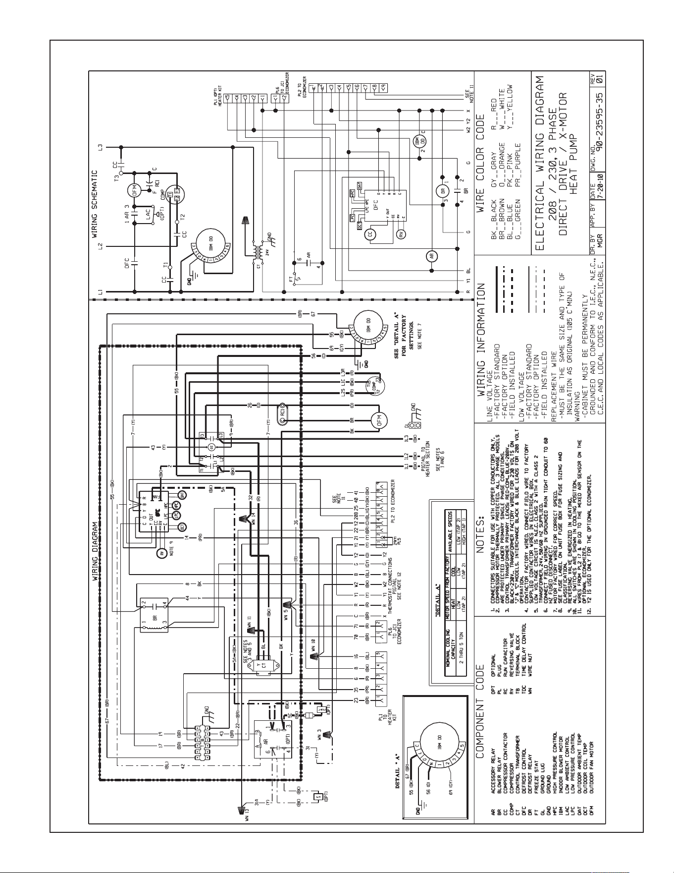
71
FIGURE 22
W
IRING DIAGRAM
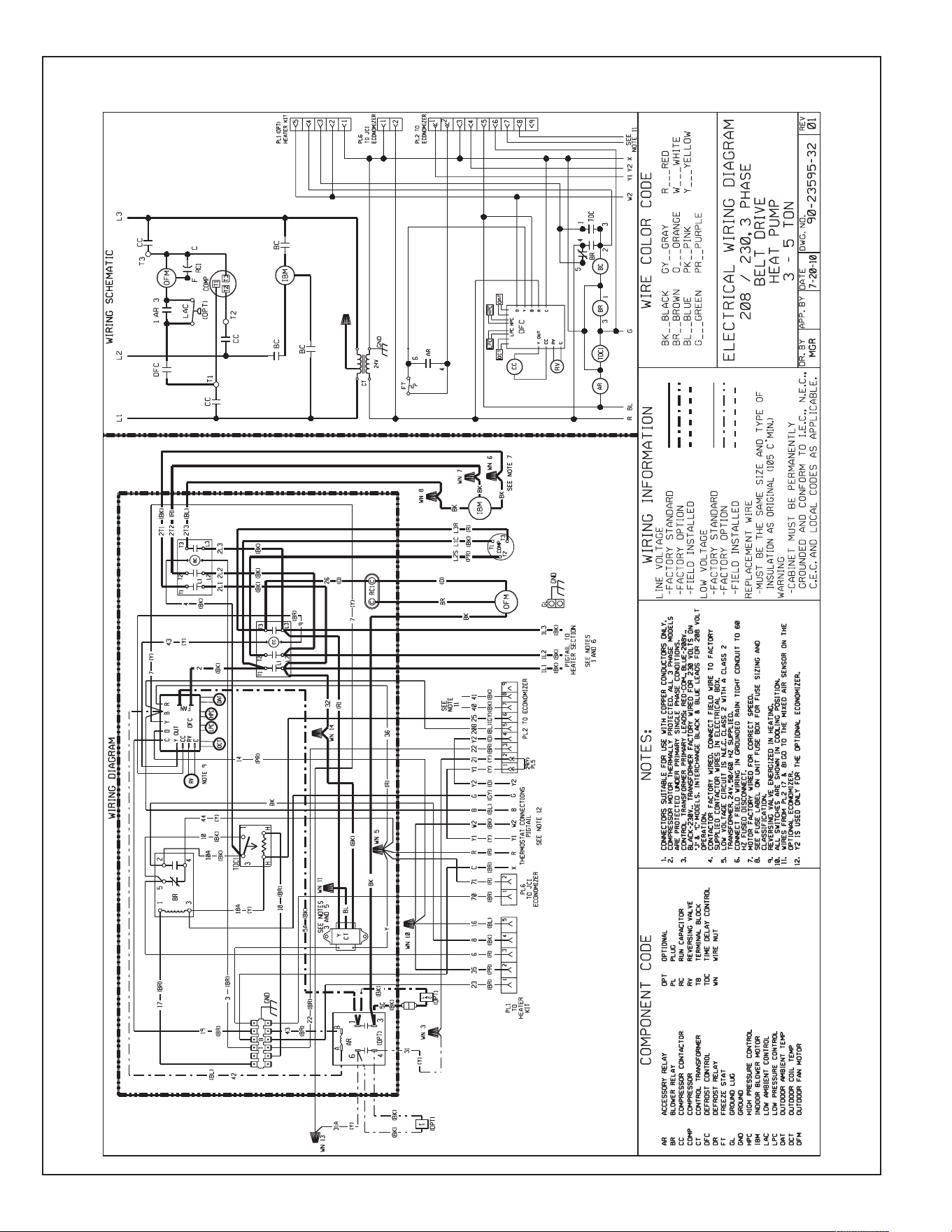
72
FIGURE 23
W
IRING DIAGRAM
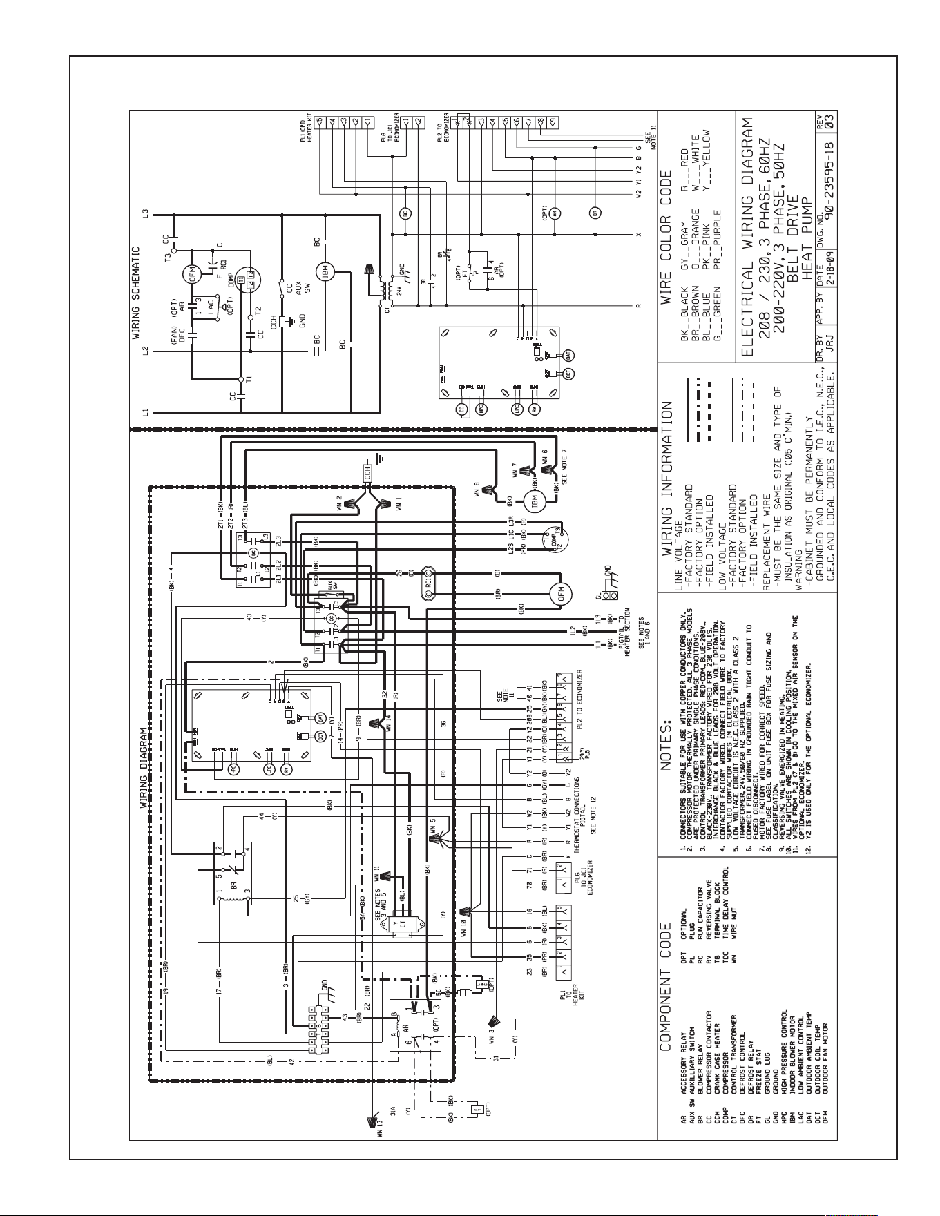
73
FIGURE 24
W
IRING DIAGRAM
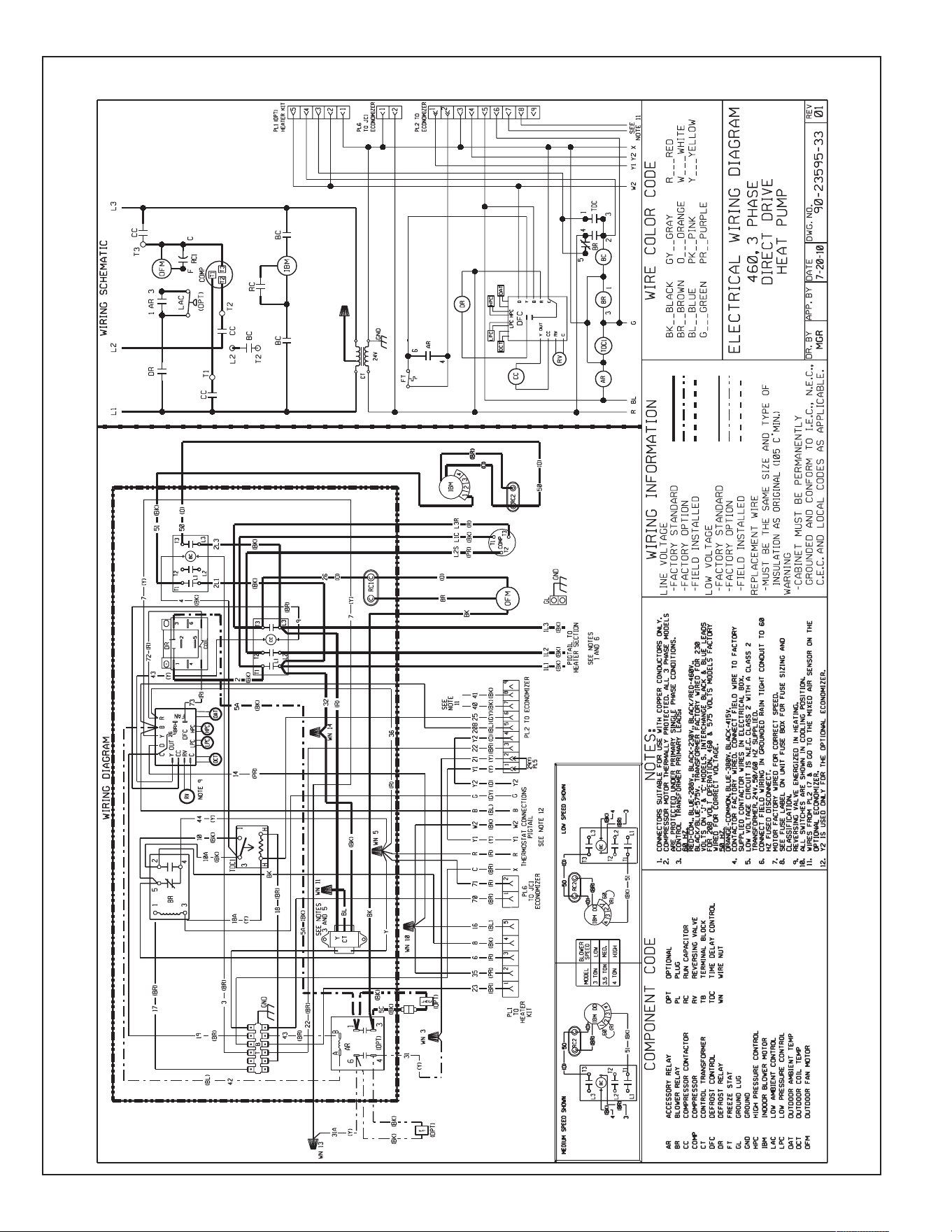
74
FIGURE 25
W
IRING DIAGRAM
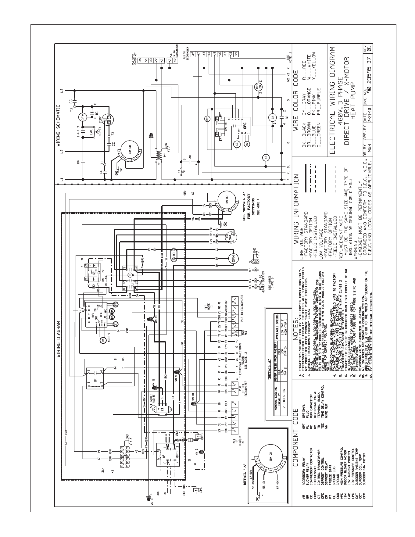
75
FIGURE 26
W
IRING DIAGRAM
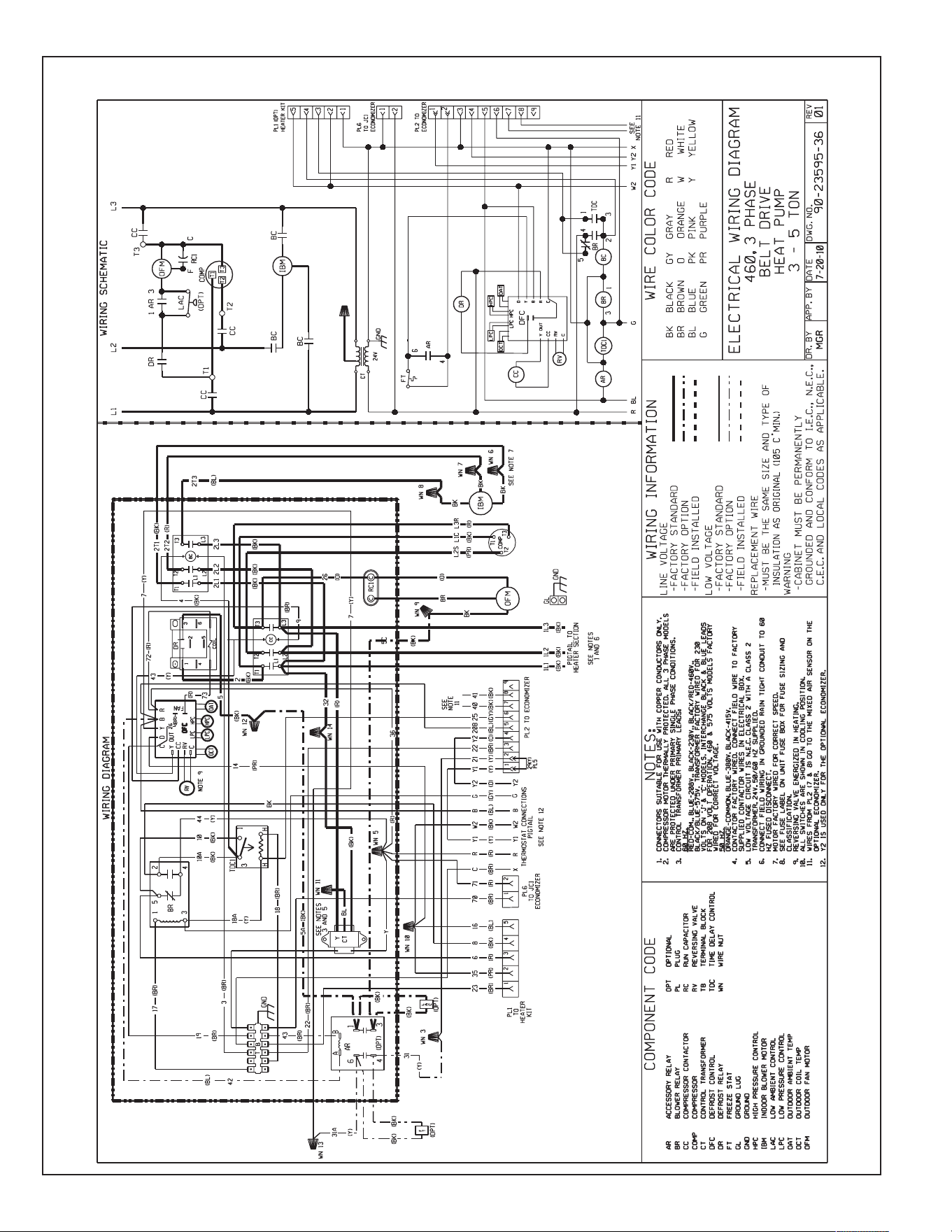
76
FIGURE 27
W
IRING DIAGRAM
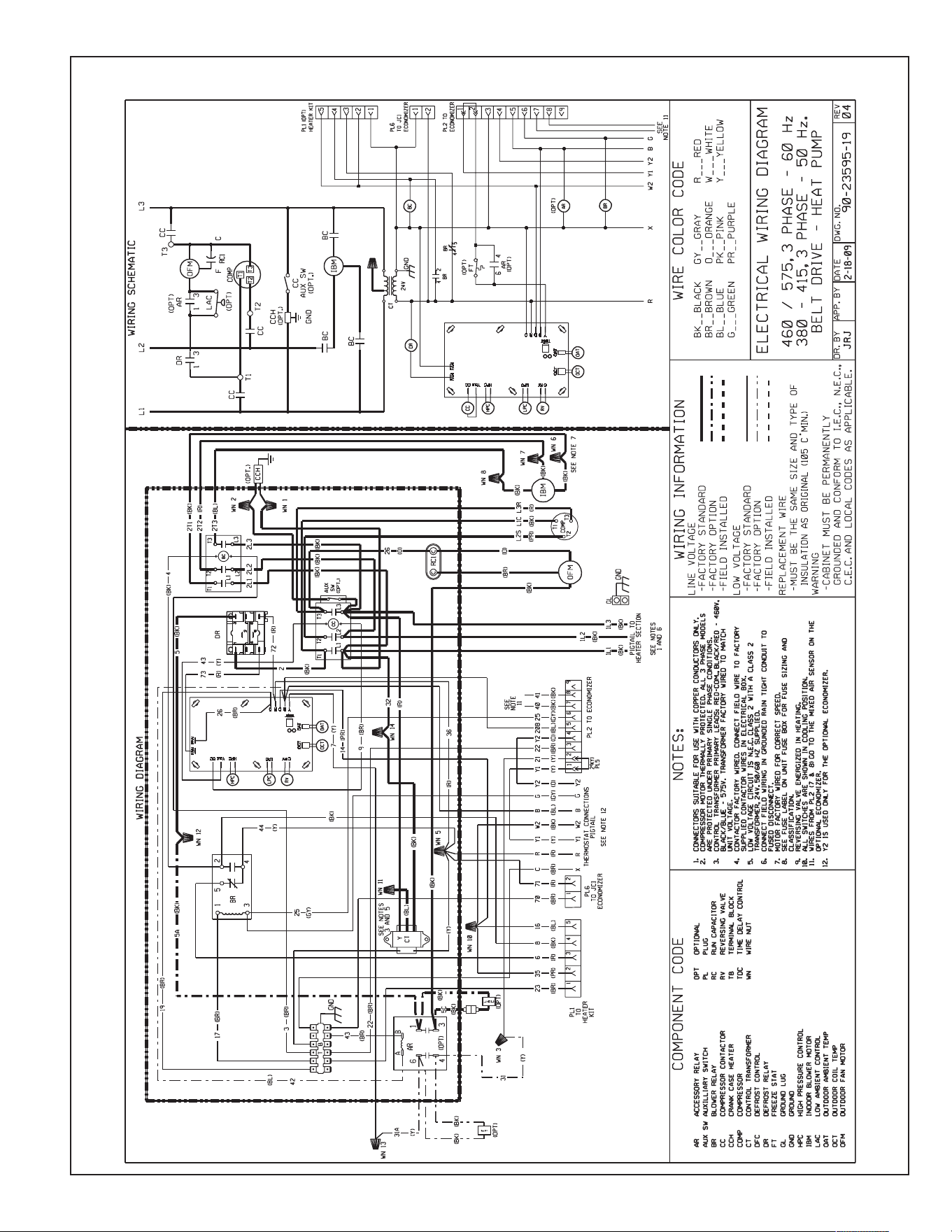
77
FIGURE 28
W
IRING DIAGRAM
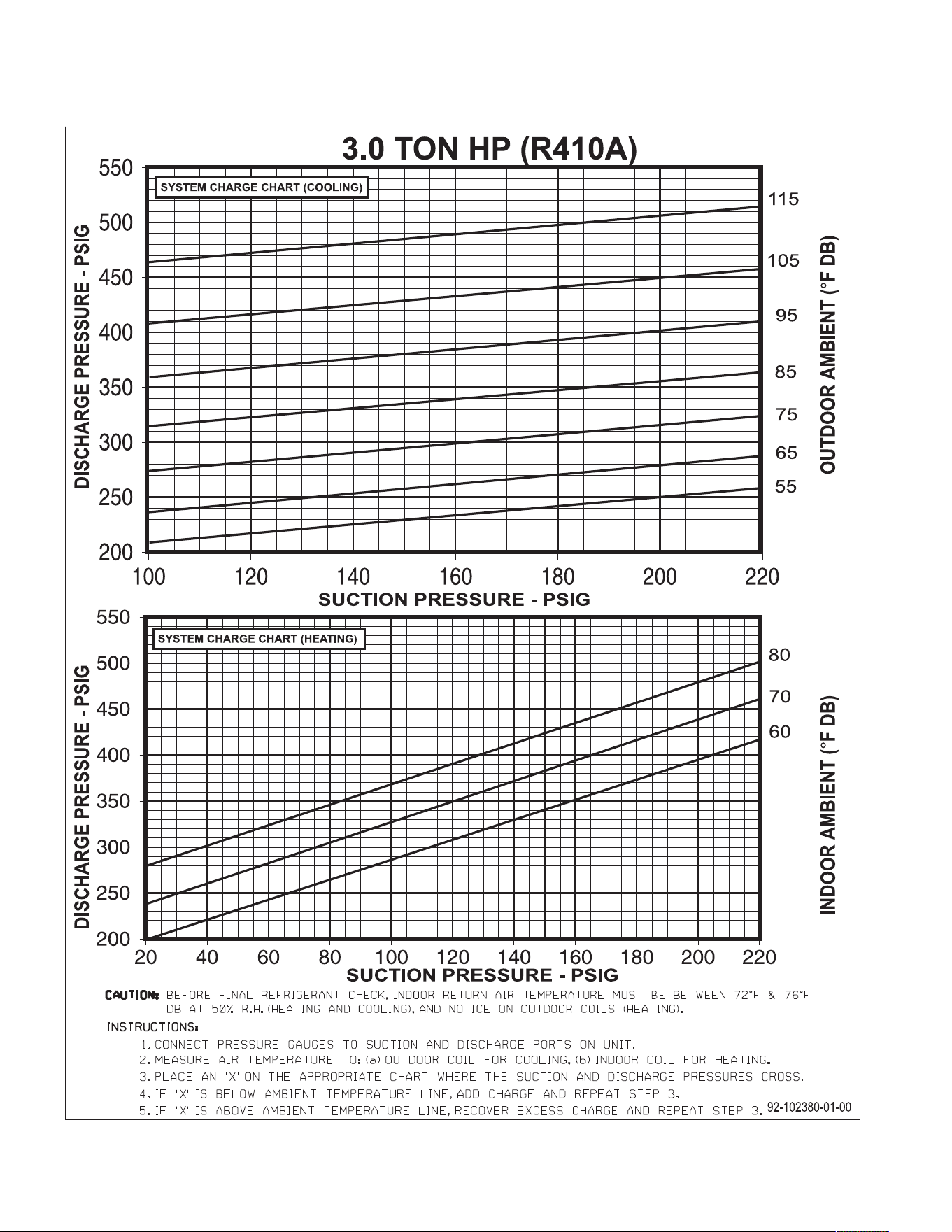
78
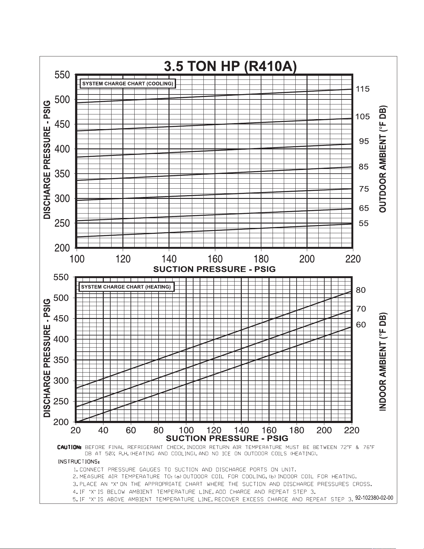
79
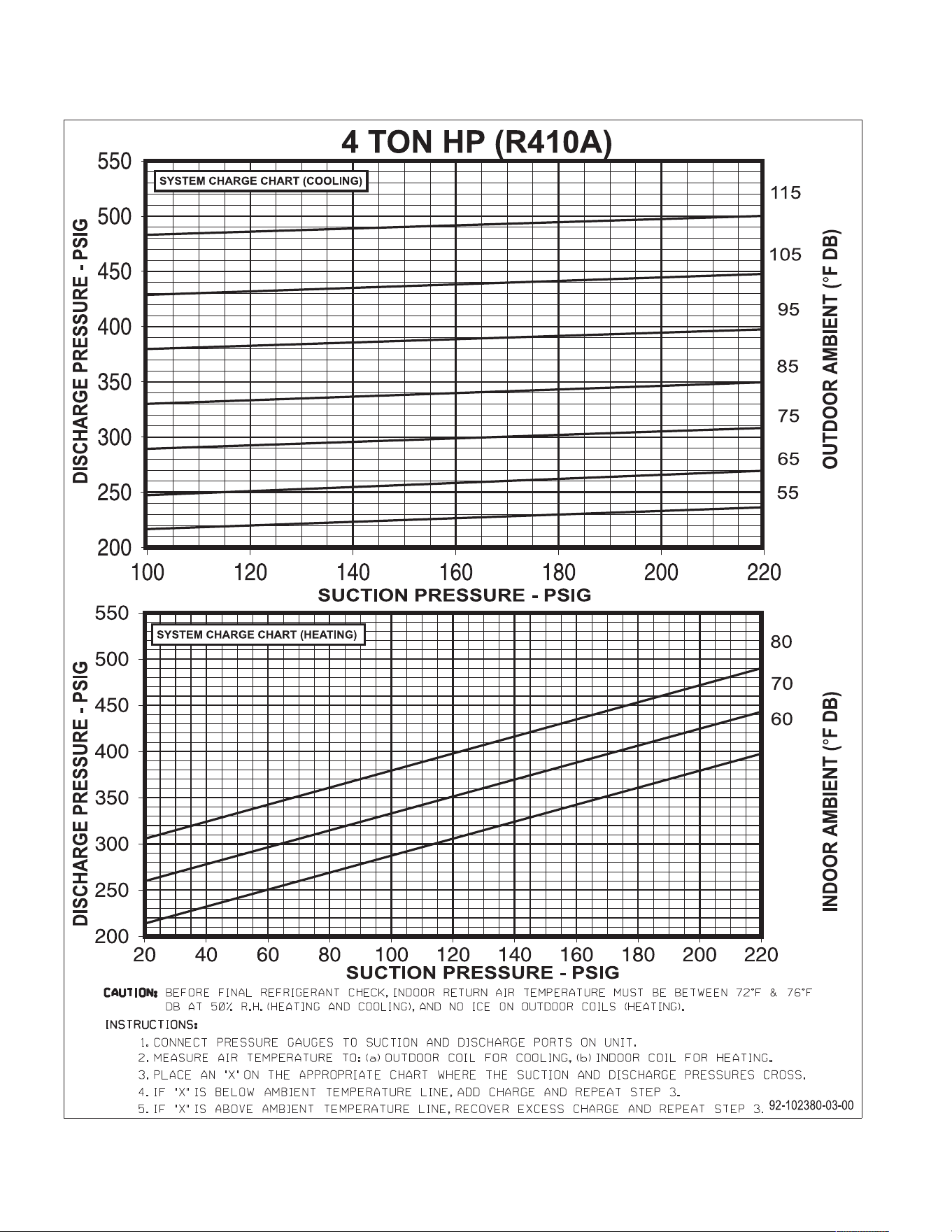
80
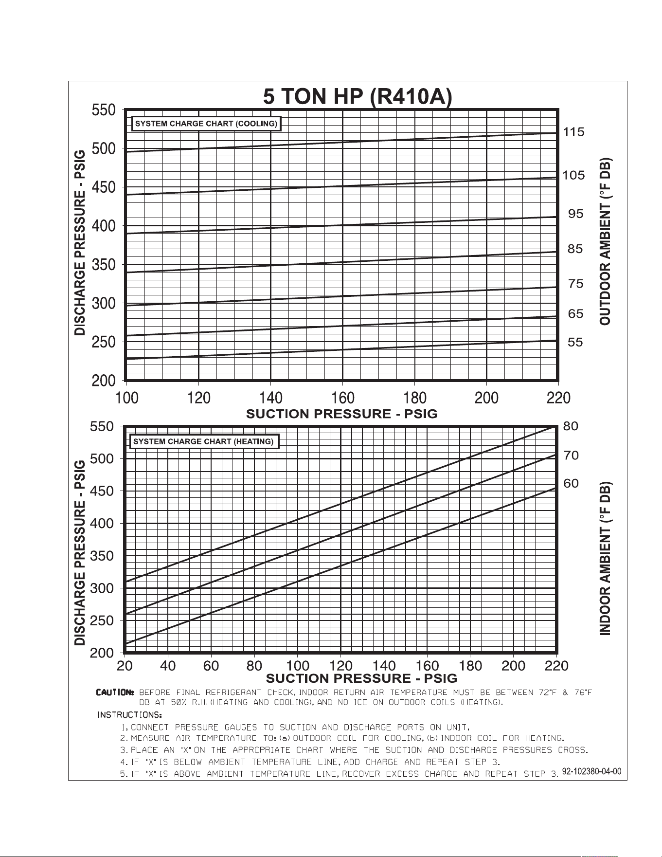
81
5 TON – 13 SEER
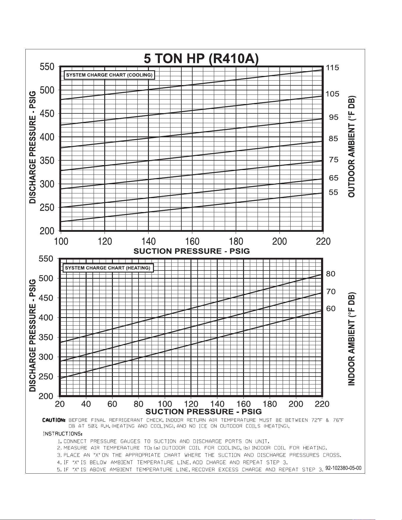
82
5 TON – 14 SEER
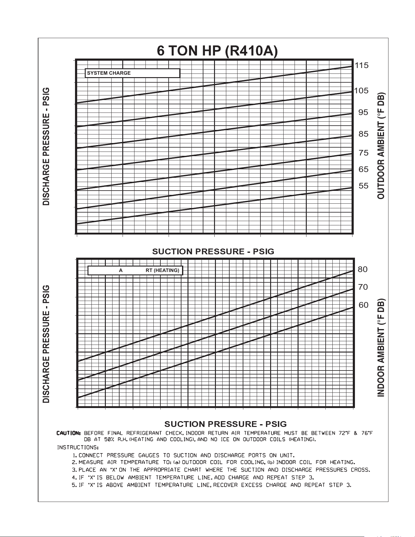
83
200
250
300
350
400
450
500
550
100 120 140 160 180 200 220
200
250
300
350
400
450
500
550
20 40 60 80 100 120 140 160 180 200 220
92-102380-06-00
6 TON HP (R410A)
SUCTION PRESSURE - PSIG
DISCHARGE PRESSURE - PSIG
OUTDOOR AMBIENT
(°F
DB)
DISCHARGE PRESSURE - PSIG
INDOOR AMBIENT (°F DB)
55
65
75
85
95
105
115
SUCTION PRESSURE - PSIG
60
70
80
600
600
SYSTEM CHARGE CHART (HEATING)
SYSTEM CHARGE CHART (COOLING)
84
CM 0913
SYMPTOM POSSIBLE CAUSE REMEDY
Unit will not run • Power off or loose electrical connection • Check for correct voltage at compressor contactor in control
box
•
Thermostat out of calibration-set too high • Reset
•
Defective contactor • Check for 24 volts at contactor coil - replace if contacts are
o
pen
•
Blown fuses • Replace fuses
• Transformer defective • Check wiring-replace transformer
• High pressure control open (if provided) • Reset-also see high head pressure remedy-
• Interconnecting low voltage wiring damaged • Replace thermostat wiring
Condenser fan runs, compressor • Run capacitor defective (single phase only) • Replace
d
oesn’t • Loose connection • Check for correct voltage at compressor -
c
heck & tighten all connections
•
Compressor stuck, grounded or open motor winding, • Wait at least 2 hours for overload to reset.
open internal overload. If still open, replace the compressor.
• Low voltage condition At compressor terminals, voltage must be within 10% of rating
• Low voltage condition • Add start kit components
I
nsufficient cooling • Improperly sized unit • Recalculate load
• Improper airflow • Check - should be approximately 400 CFM per ton.
• Incorrect refrigerant charge • Charge per procedure attached to unit service panel
• Air, non-condensibles or moisture in system • Recover refrigerant, evacuate & recharge, add filter drier
• Incorrect voltage • At compressor terminals, voltage must be within 10% of rating
p
late volts when unit is operating.
Compressor short cycles • Incorrect voltage • At compressor terminals, voltage must be ±10% of
nameplate marking when unit is operating.
• Defective overload protector • Replace - check for correct voltage
• Refrigerant undercharge • Add refrigerant
Registers sweat • Low evaporator airflow • Increase speed of blower or reduce restriction - replace air
filter
High head-low vapor pressures • Restriction in liquid line, expansion device or filter drier • Remove or replace defective component
• Flow check piston size too small • Change to correct size piston
• Incorrect capillary tubes • Change coil assembly
• TXV does not open • Replace TXV
High head-high or normal vapor • Dirty condenser coil • Clean coil
pressure - Cooling mode • Refrigerant overcharge • Correct system charge
• Condenser fan not running • Repair or replace
• Air or non-condensibles in system • Recover refrigerant, evacuate & recharge
High head-high or normal vapor • Low air flow - condenser coil • Check filters - correct to speed
pressure - Heating mode • Refrigerant overcharge • Correct system charge
• Air or non-condensibles in system • Recover refrigerant, evacuate & recharge
• Dirty condenser coil • Check filter - clean coil
Low head-high vapor pressures • Defective Compressor valves • Replace compressor
Low vapor - cool compressor - • Low evaporator airflow • Increase speed of blower or reduce restriction - replace air
iced evaporator coil filter
• Operating below 65°F outdoors • Add Low Ambient Kit
• Moisture in system • Recover refrigerant - evacuate & recharge - add filter drier
• TXV limiting refrigerant flow • Replace TXV
High vapor pressure • Excessive load • Recheck load calculation
• Defective compressor • Replace
Fluctuating head & vapor • TXV hunting • Check TXV bulb clamp - check air distribution on coil - replace
pressures TXV
• Air or non-condensate in system • Recover refrigerant, evacuate & recharge
Gurgle or pulsing noise at • Air or non-condensibles in system • Recover refrigerant, evacuate & recharge
expansion device or liquid line
TROUBLE SHOOTING CHART
D
ISCONNECT ALL POWER TO UNIT BEFORE SERVICING. CONTACTOR MAY BREAK ONLY ONE SIDE. FAILURE
TO SHUT OFF POWER CAN CAUSE ELECTRICAL SHOCK RESULTING IN PERSONAL INJURY OR DEATH.
WARNING
!
SEE DEMAND DEFROST CONTROL SECTION FOR DEFROST BOARD FLASH CODES (6 TON UNIT ONLY).