U S E R G U I D E
+
S E R V I C E M A N U A L
Model: URRE324-SS01A
USER GUIDE & SERVICE MANUAL
Table of Contents
Click on any section below to jump directly there
Intro
Safety
Safety and Warning
Disposal And Recycling
Installation
Environmental Requirements
Electrical
Side by Side Installation
Anti-Tip Bracket
General Installation
Grille Installation
Door Swing
Door Stop
Door Adjust
Maintenance
Cleaning
Cleaning Condenser
Extended Non-Use
Operating Instructions
First Use
Control Operation
Airflow and Product Loading
Service
Troubleshooting
Wire Diagram
Product Liability
R600a Specifications
System Diagnosis Guide
Compressor Specifications
Troubleshooting Extended
Thermistor
Defrost
Warranty
USER GUIDE
Introduction
Welcome to U-Line
Congratulations on your U-Line purchase! At U-Line, we pride ourselves on delivering quality appliances that are visually elevated.
Our blend of functionality, beautiful aesthetics, and inspired innovations ensures that every detail, no matter how small, contributes to
a superior product experience. Our versatile applications span residential indoors and outdoors, marine, and commercial settings. Our
diverse product line includes a wide variety of ice machines and refrigeration driven by design since 1962.
U-Line creates products designed for a modern lifestyle – beautiful and functional refrigeration that properly preserves food, beverages,
and wine. With a focus on seamless integration and designer preferred features, U-Line speaks to those seeking a rened aesthetic.
Featuring the simplest panel installation in the industry with fully integrated adjustable grille capabilities, U-Line is redening the
industry standard on integration—making our products Built-In to Stand Out®. Since joining the Middleby family of brands in 2014, we
have continued to innovate and redene the refrigeration landscape.
Thank you for your support,
U-Line
Right Product. Right Place. Right Temperature.
®
Product Information
Looking for additional information on your product? User Guides, Spec Sheets, CAD Drawings, and Product Warranty information are
available digitally on u-line.com.
Property Damage and Injury Concerns
In the unlikely event property damage or personal injury is suspected related to a U-Line product, please take the following steps:
1. Our customer service team must be contacted immediately at +1.616.754.5601.
2. Service or repairs performed on the product without prior written approval from our factory is not permitted. If the product has been
altered or repaired in the eld without prior written approval, claims will not be eligible.
Reach Out
Middleby Refrigeration
1260 E Van Deinse
Greenville, MI 48838
+1.616.754.5601
customerservice@middlebyrefrigeration.com
Let’s Connect
@ulinecorp | u-line.com
3
USER GUIDE
Safety and Warning
Safety and Warning
NOTICE
Please read all instructions before installing,
operating, or servicing the appliance.
Use this appliance for its intended purpose only and follow
these general precautions with those listed throughout this
guide:
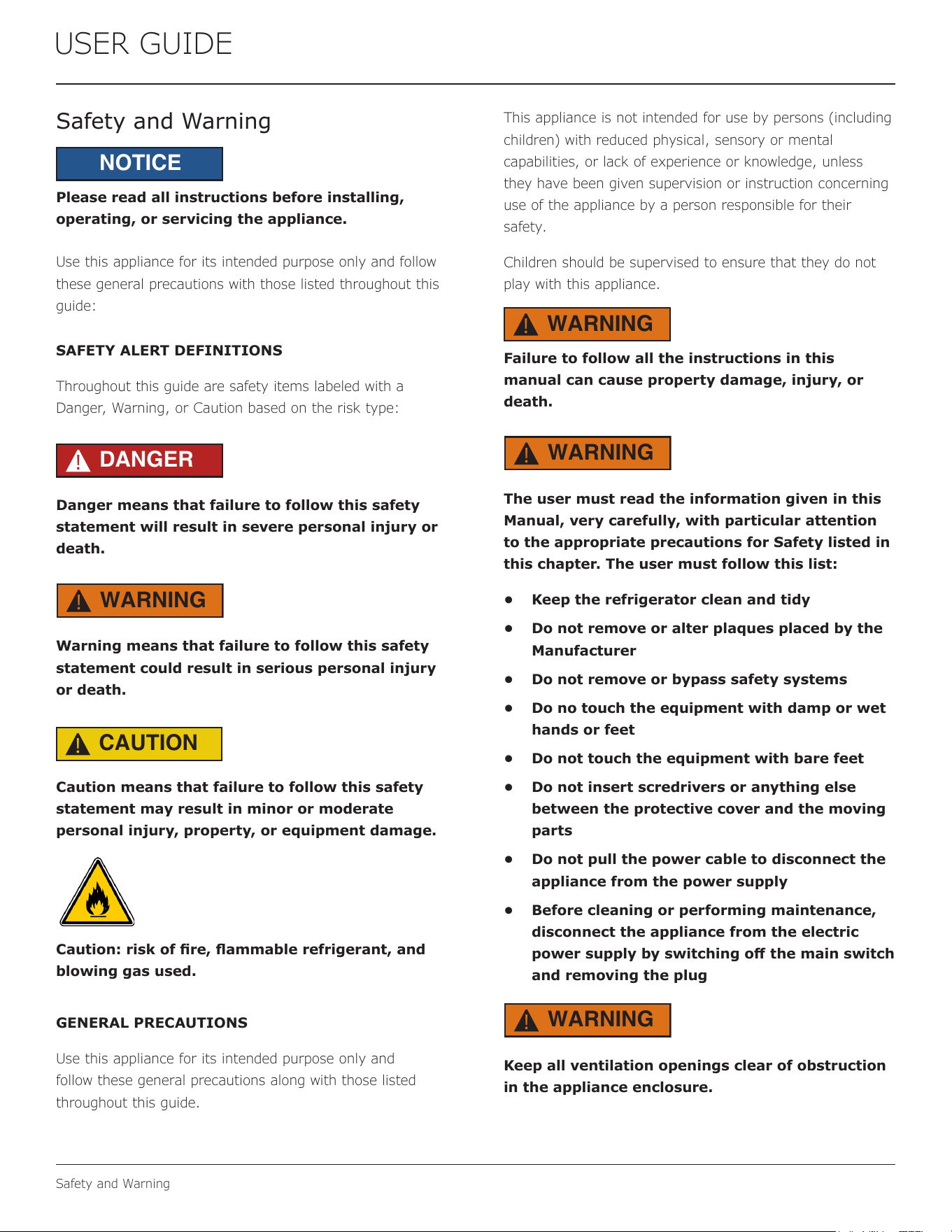
SAFETY ALERT DEFINITIONS
Throughout this guide are safety items labeled with a
Danger, Warning, or Caution based on the risk type:
DANGER
!
Danger means that failure to follow this safety
statement will result in severe personal injury or
death.
WARNING
!
Warning means that failure to follow this safety
statement could result in serious personal injury
or death.
CAUTION
!
Caution means that failure to follow this safety
statement may result in minor or moderate
personal injury, property, or equipment damage.
Caution: risk of re, ammable refrigerant, and
blowing gas used.
GENERAL PRECAUTIONS
Use this appliance for its intended purpose only and
follow these general precautions along with those listed
throughout this guide.
This appliance is not intended for use by persons (including
children) with reduced physical, sensory or mental
capabilities, or lack of experience or knowledge, unless
they have been given supervision or instruction concerning
use of the appliance by a person responsible for their
safety.
Children should be supervised to ensure that they do not
play with this appliance.
WARNING
!
Failure to follow all the instructions in this
manual can cause property damage, injury, or
death.
WARNING
!
The user must read the information given in this
Manual, very carefully, with particular attention
to the appropriate precautions for Safety listed in
this chapter. The user must follow this list:
• Keep the refrigerator clean and tidy
• Do not remove or alter plaques placed by the
Manufacturer
• Do not remove or bypass safety systems
• Do no touch the equipment with damp or wet
hands or feet
• Do not touch the equipment with bare feet
• Do not insert scredrivers or anything else
between the protective cover and the moving
parts
• Do not pull the power cable to disconnect the
appliance from the power supply
• Before cleaning or performing maintenance,
disconnect the appliance from the electric
power supply by switching o the main switch
and removing the plug
WARNING
!
Keep all ventilation openings clear of obstruction
in the appliance enclosure.
4
USER GUIDE
Safety and Warning
WARNING
!
Do not store explosive substances, such as
aerosol cans, with a ammable propellant in this
appliance.
WARNING
!
Comply with local regulations regarding disposal
of the appliance for its ammable refrigerant and
blowing gas. Before disposing of the appliance,
remove the doors to prevent child entrapment.
WARNING
!
Do not use mechanical devices or other means
to accelerate the defrosting process, other than
those recommended by the manufacturer.
WARNING
!
The refrigerator must not be used:
• For purposes diering from its intended use
• In an explosive, aggressive atmosphere, or
where there is a high concentration of oily
substances or powders suspended in the air
• In an atmosphere with a re risk
• When exposed to bad weather
• With adapters, multiple sockets, or extension
leads
WARNING
!
If repairs or maintenance have to be carried out
requiring the removal of the safety devices, all
power sources must be switched o. Deactivate
the electric plant, turning o the main switch and
pulling out the plug. After the work is nished, all
safety devices must be re-activated.
WARNING
!
Do not damage the refrigerating circuit.
WARNING
!
Do not use electrical appliances inside the food/
ice storage compartments unless they are of the
type recommended by the manufacturer.
NOTICE
Never install or operate the unit behind closed
doors. Be sure front grille is free of obstruction.
Obstructing free airow can cause the unit to
malfunction and will void the warranty.
NOTICE
This appliance is intended to be used in
commercial and similar applications such
as: Communities, restaurants, hotels, retail
providers, and similar applications.
GENERAL SAFETY
WARNING
!
Do not operate this equipment without properly
placing and securing all covers and access panels.
Failure to comply with this procedure can cause
property damage, injury, or death.
WARNING
!
Do not use or store gasoline or other ammable
vapors or liquids in the vicinity of this or any
other appliance. Failure to comply can cause
property damage, injury, or death.
WARNING
!
In the event of a power failure, do not attempt
to operate this appliance. Failure to comply can
cause property damage, injury, or death.
WARNING
!
U-Line accepts no responsibility for any
situation resulting from work carried out in an
unprofessional manner, or from the incorrect
interpretation or application of regulations.
WARNING
!
Repair work must only be performed by U-Line’s
approved distributors or one of its authorized
representatives. U-Line accepts no responsibility
for any situation resulting from work performed
by untrained and/or unauthorized technicians.
5
USER GUIDE
Disposal and Recycling
Disposal and Recycling
RISK OF CHILD ENTRAPMENT. Before you throw
away your old refrigerator or freezer, take o
the doors and leave shelves in place so children
may not easily climb inside.
If the unit is being removed from service for disposal,
check and obey all federal, state, and local regulations
regarding the disposal and recycling of refrigeration
appliances, and follow these steps completely:
1. Remove all consumable contents from the unit.
2. Unplug the electrical cord from its socket.
3. Remove the door(s)/drawer(s).
DANGER
!
6
USER GUIDE
Environmental Requirements
Environmental Requirements
This unit is designed to operate between 45°F (7°C)
and 77°F (25°C). For example, this unit will be eective
whether you operate it in a cold room or hot kitchen.
Higher ambient temperatures may reduce the unit’s ability
to reach low temperatures.
For best performance, keep the unit out of direct sunlight
and away from heat generating equipment.
In climates where high humidity and dew points are
present, condensation may appear on outside surfaces.
This is considered normal. The condensation will evaporate
when the humidity drops.
CAUTION
!
Damages caused by ambient temperatures of
40°F (4°C) or below are not covered by the
warranty.
7
USER GUIDE
Electrical
Electrical
ELECTRICAL WARNINGS
WARNING
!
Never remove the round grounding prong from
the plug and never use a two-prong grounding
adapter.
WARNING
!
Altering, cutting or removing power cord,
removing power plug, or direct wiring can cause
serious injury, re, loss of property and/or life,
and will void the warranty.
WARNING
!
Never use an extension cord to connect power to
the unit.
WARNING
!
Always keep your working area dry.
WARNING
!
Electrical connections should be performed
only by a certied professional. Electrical and
grounding connections must comply with the
applicable portions of the National Electric Code
and/or all local electric codes. Failure to comply
with this procedure can cause property damage,
injury, or death.
WARNING
!
Make sure all facility electrical connections
comply with all local and federal electrical code
regulations.
WARNING
!
Electrical connections or any work required on
the electrical circuits inside the appliance must be
performed by certied technicians in compliance
with local, state, and federal regulations.
WARNING
!
Before connecting the unit to the electrical
supply, verify that the electrical and grounding
connections comply with the applicable portions
of the National Electric Code and/or other local
electrical codes. Failure to comply with this
procedure can cause property damage, injury, or
death.
WARNING
!
Before connecting the unit to the electrical
supply, verify that the electrical connection
agrees with the specications on the data plate.
Failure to comply with this procedure can cause
property damage, injury, or death.
WARNING
!
Appliance must be connected to a grounded,
metal, permanent wiring system. Or an
equipment-grounding conductor must be run
with the circuit conductors and connected to the
equipment-grounding terminal or lead on the
appliance. Failure to comply with this procedure
can cause property damage, injury, or death.
WARNING
!
Appliances equipped with a exible electric
supply cord, are provided with a three-prong
grounding plug. This plug must be connected
into a properly grounded three-prong receptacle.
Failure to comply with this procedure can cause
property damage, injury, or death.
WARNING
!
If the receptacle is not the proper grounding
type, contact an electrician. Do not remove the
grounding prong from the plug. Failure to comply
with this procedure can cause property damage,
injury, or death.
NOTICE
Electrical installation must observe all state and
local codes. This unit requires connection to a
grounded (three-prong), polarized receptacle that
has been placed by a qualied electrician.
8
USER GUIDE
Electrical
ELECTRICAL LOCKOUT/TAGOUT PROCEDURE
WARNING
!
Before removing any sheet metal panels,
always perform the Electrical LOCKOUT/TAGOUT
Procedure. Be sure all circuits are disconnected.
Failure to comply with this procedure can cause
property damage, injury, or death.
WARNING
!
Before performing any service that involves
electrical connection or disconnection and/or
exposure to electrical components, always follow
the Electrical LOCKOUT/TAGOUT Procedure.
Disconnect all circuits. Failure to comply can
cause property damage, injury or death.
The Electrical LOCKOUT/TAGOUT Procedure
is used to protect personnel working on an
electrical appliance. Before performing any
maintenance or service that requires exposure to
electrical components, follow these steps:
1. In electrical box, place appliance circuit
breaker into OFF position.
2. Place a lock or other device on electrical box
cover to prevent someone from placing circuit
breaker ON.
3. Place a tag on electrical box cover to indicate
that appliance has been disconnected for
service and power should not be restored
until tag is removed by maintenance
personnel.
4. Disconnect appliance power cord from
electrical outlet.
5. Place a tag on the cord to indicate that unit
has been disconnected for service and power
should not be restored until tag is removed by
maintenance personnel.
The unit requires a grounded and polarized 208 – 220 VAC,
60 Hz, 30A power supply (normal household current).
An individual, properly grounded branch circuit or circuit
breaker is recommended. A GFCI (ground fault circuit
interrupter) is usually not required for xed location
appliances and is not recommended for your unit because
it could be prone to nuisance tripping. However, be sure to
consult your local codes.
See CUTOUT & PRODUCT DIMENSIONS for recommended
receptacle location.
9
USER GUIDE
Side-by-Side Installation
Side-by-Side Installation
OTHER SITE REQUIREMENTS
Side-by-Side Installation
Units must operate from separate, properly grounded
electrical receptacles placed according to each unit’s
electrical specifications requirements.
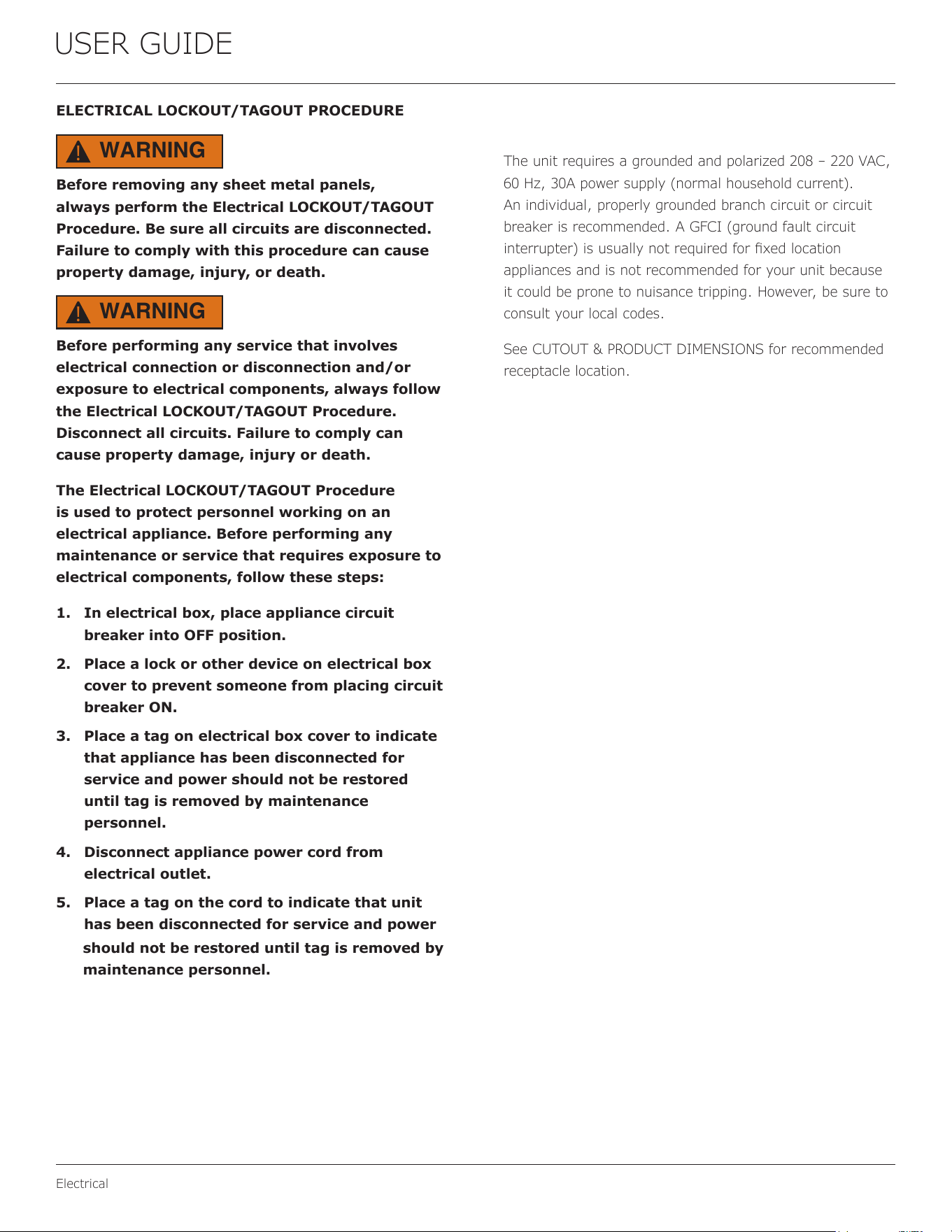
Cutout width for a side-by-side installation is the total of
the widths listed under Cutout Dimensions in each unit’s
Installation Guide. Each door can be opened individually
(one at a time) without interference.
However, to ensure unobstructed door swing (opening
both doors at the same time), 1/4" (6.4 mm) of space
needs to be maintained between the units.
Hinge-by-Hinge Installation (Mullion)
When installing two units hinge-by-hinge, 13/16" (22 mm)
is required for integrated models. Additional space may be
needed for any knobs, pulls or handles installed.
Stainless steel models which include the standard stainless
handle will require 4-9/16" (116 mm) to allow both doors
to open to 90° at the same time.
1/4" (6 mm)
13/16" (22 mm)
4-9/16" (116 mm)
10
USER GUIDE
Anti-Tip Bracket
Anti-Tip Bracket
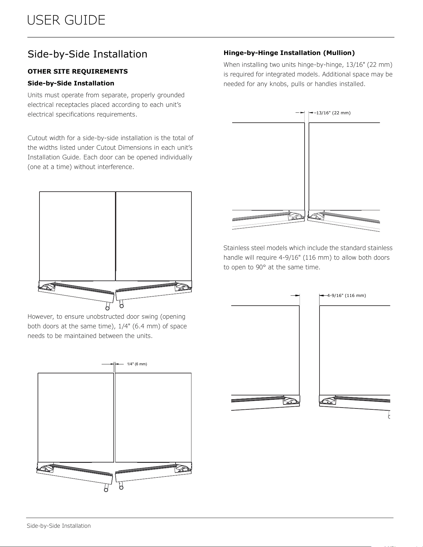
1. Slide unit out so screws on side of unit are easily
accessible.
2. Locate the 3 holes on side of the unit.
3. Place bracket over holes and attach to unit with 3 of
the screws provided with the bracket.
4. Repeat on the opposite side.
5. Gently push unit into position. Be careful not to
entangle the electrical cord.
6. Check to be sure the unit is level from front to back
and side to side. Make any necessary adjustments.
The unit’s top surface should be approximately 1⁄8”
(3 mm) below the countertop.
7. Open door to access the holes in the bracket.
8. Use 3 provided screws to secure each bracket into
adjoining surface.
11
USER GUIDE
General Installation
General Installation
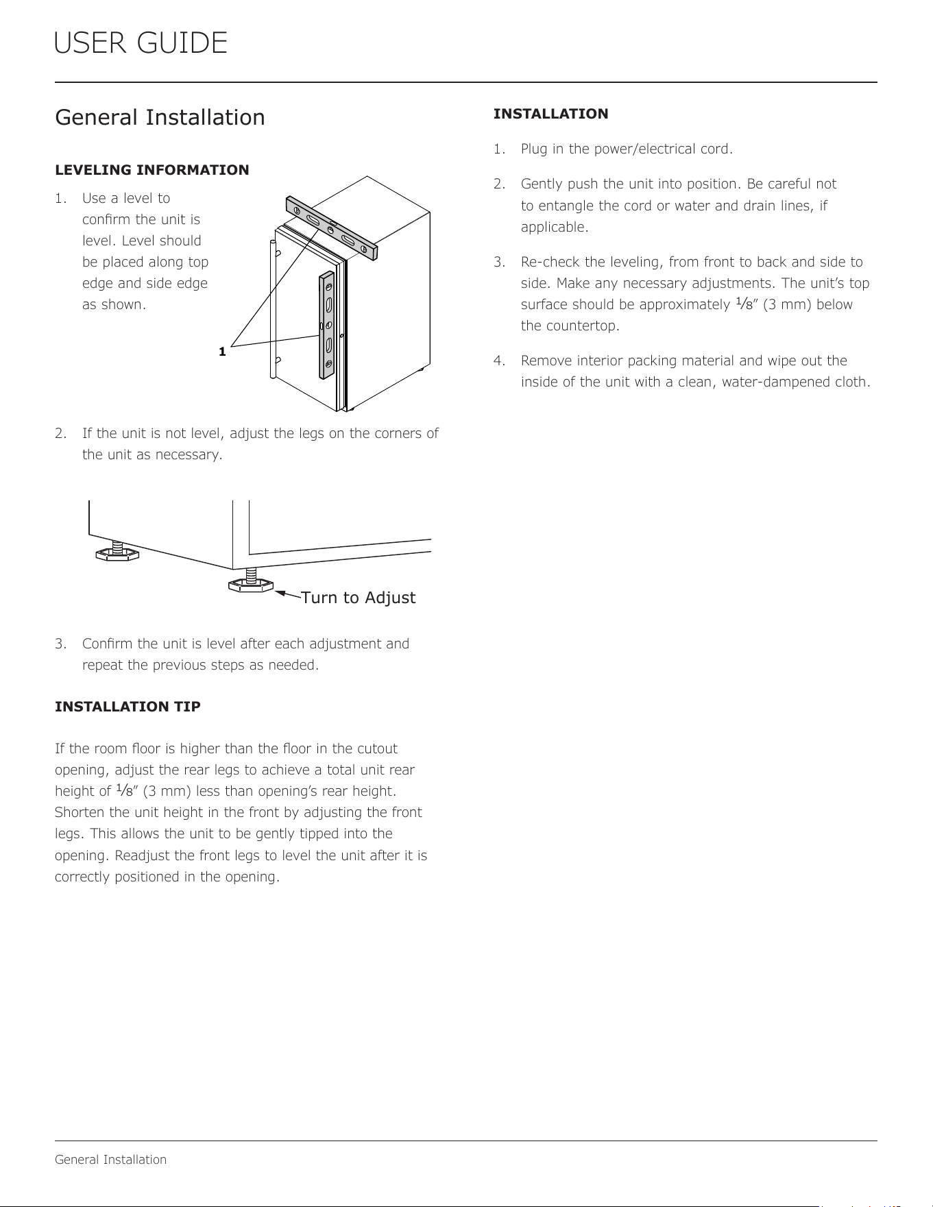
LEVELING INFORMATION
1. Use a level to
conrm the unit is
level. Level should
be placed along top
edge and side edge
as shown.
2. If the unit is not level, adjust the legs on the corners of
the unit as necessary.
3. Conrm the unit is level after each adjustment and
repeat the previous steps as needed.
INSTALLATION TIP
If the room oor is higher than the oor in the cutout
opening, adjust the rear legs to achieve a total unit rear
height of
1⁄8” (3 mm) less than opening’s rear height.
Shorten the unit height in the front by adjusting the front
legs. This allows the unit to be gently tipped into the
opening. Readjust the front legs to level the unit after it is
correctly positioned in the opening.
INSTALLATION
1. Plug in the power/electrical cord.
2. Gently push the unit into position. Be careful not
to entangle the cord or water and drain lines, if
applicable.
3. Re-check the leveling, from front to back and side to
side. Make any necessary adjustments. The unit’s top
surface should be approximately
1⁄8” (3 mm) below
the countertop.
4. Remove interior packing material and wipe out the
inside of the unit with a clean, water-dampened cloth.
1
Turn to Adjust
12
USER GUIDE
Grille Installation
Grille Installation
REMOVING AND INSTALLING GRILLE
Disconnect electric power to the unit before
removing the grille.
When using the unit, the grille must be installed.
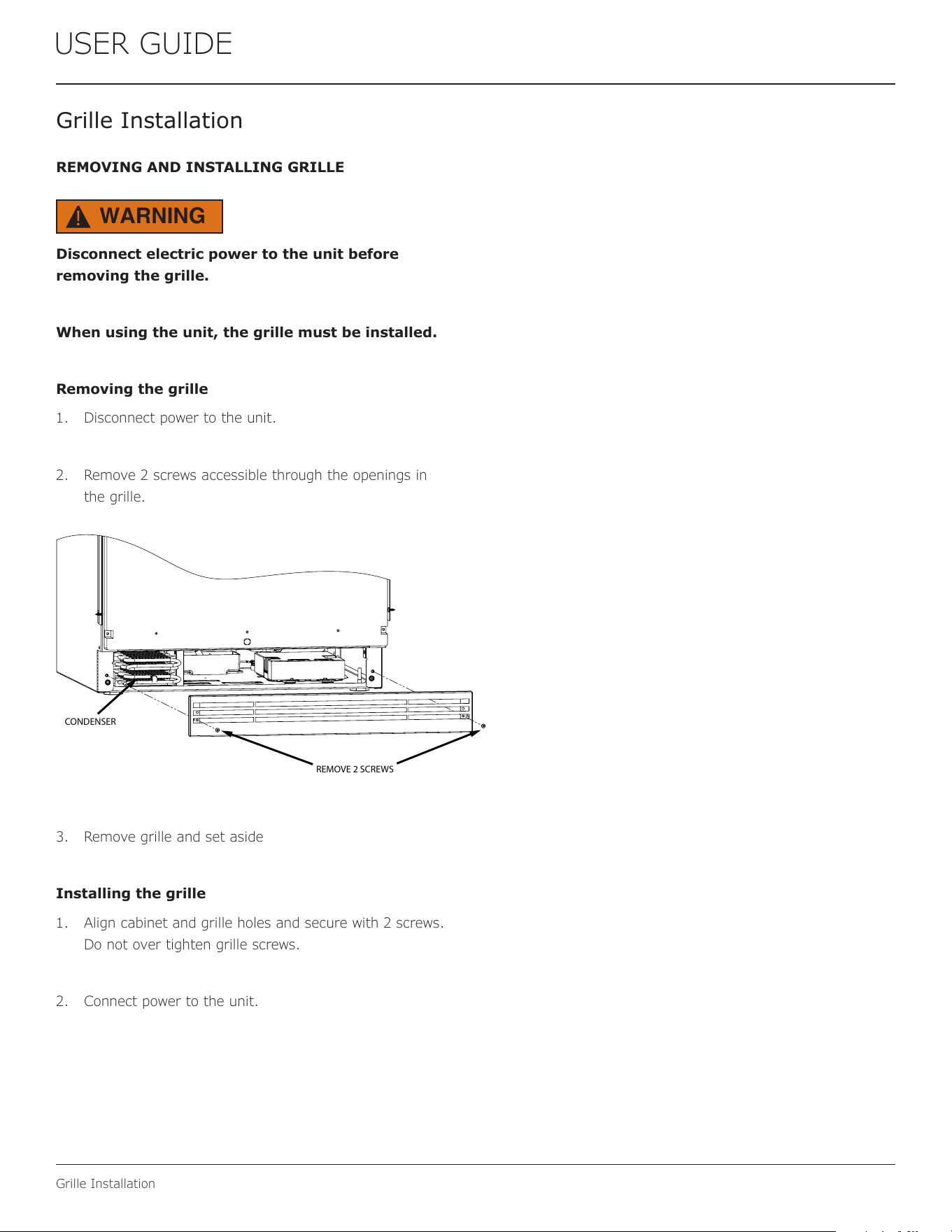
Removing the grille
1. Disconnect power to the unit.
2. Remove 2 screws accessible through the openings in
the grille.
3. Remove grille and set aside
Installing the grille
1. Align cabinet and grille holes and secure with 2 screws.
Do not over tighten grille screws.
2. Connect power to the unit.
WARNING
!
REMOVE 2 SCREWS
CONDENSER
13
USER GUIDE
Door Swing
Door Swing
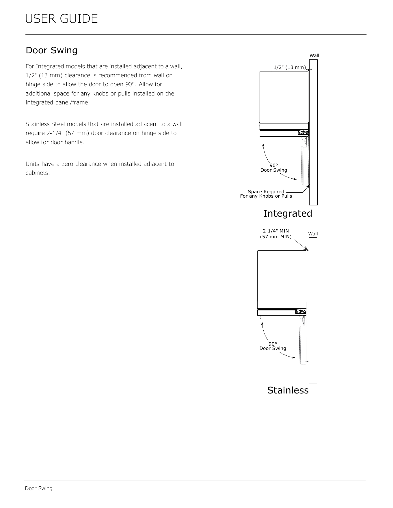
For Integrated models that are installed adjacent to a wall,
1/2" (13 mm) clearance is recommended from wall on
hinge side to allow the door to open 90°. Allow for
additional space for any knobs or pulls installed on the
integrated panel/frame.
Stainless Steel models that are installed adjacent to a wall
require 2-1/4" (57 mm) door clearance on hinge side to
allow for door handle.
Units have a zero clearance when installed adjacent to
cabinets.
Wall
Wall
90°
Door Swing
90°
Door Swing
Space Required
For any Knobs or Pulls
2-1/4" MIN
(57 mm MIN)
Integrated
Stainless
1/2" (13 mm)
14
USER GUIDE
Door Stop
Door Stop
Your U-Line unit was shipped to you with the optional 90°
pin.
Your unit’s door(s) will open 115° straight from the
factory. If you would like the door stop at 90°, follow these
instructions.
NOTICE
If your unit is already undercounter, it will need
to be moved out to access the hinge.
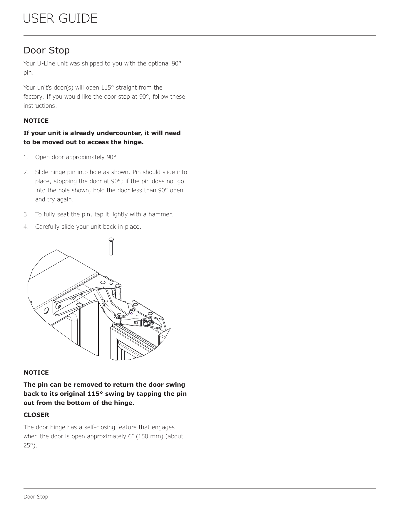
1. Open door approximately 90°.
2. Slide hinge pin into hole as shown. Pin should slide into
place, stopping the door at 90°; if the pin does not go
into the hole shown, hold the door less than 90° open
and try again.
3. To fully seat the pin, tap it lightly with a hammer.
4. Carefully slide your unit back in place.
NOTICE
The pin can be removed to return the door swing
back to its original 115° swing by tapping the pin
out from the bottom of the hinge.
CLOSER
The door hinge has a self-closing feature that engages
when the door is open approximately 6” (150 mm) (about
25°).
15
USER GUIDE
Door Adjustments
Door Adjustments
DOOR ALIGNMENT AND ADJUSTMENT
Align and adjust the door if it is not level or not sealing
properly. If the door is not sealed, the unit may not cool
properly, or excessive frost or condensation may form in
the interior.
NOTICE
Properly aligned, the door’s gasket should be
rmly in contact with the cabinet all the way
around the door (no gaps). Carefully examine the
door’s gasket to ensure that it is rmly in contact
with the cabinet. Also make sure the door gasket
is not pinched on the hinge side of the door.
Do not attempt to use the door to raise or pivot
your unit. This would put excessive stress on the
hinge system.
Alignment and Adjustment Procedure
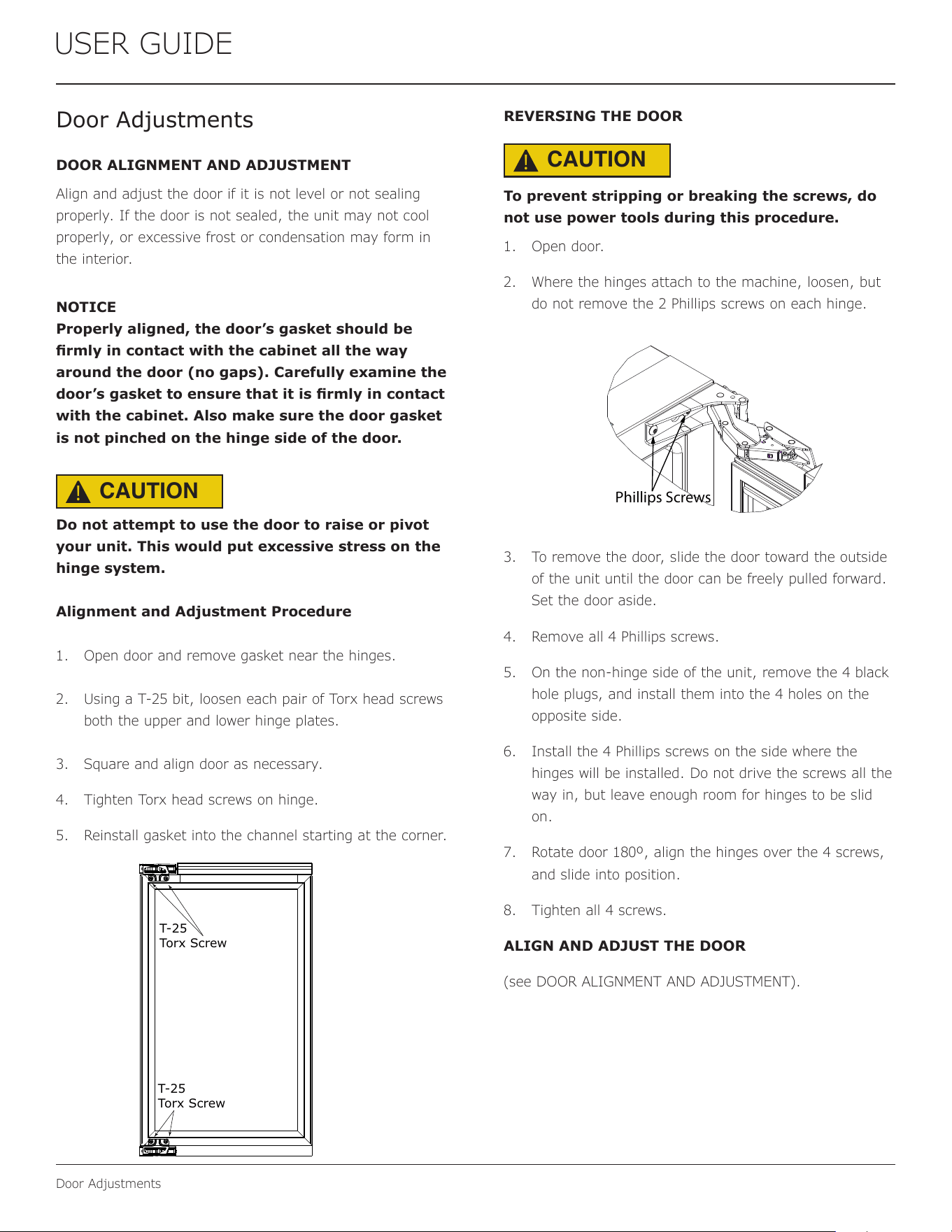
1. Open door and remove gasket near the hinges.
2. Using a T-25 bit, loosen each pair of Torx head screws
both the upper and lower hinge plates.
3. Square and align door as necessary.
4. Tighten Torx head screws on hinge.
5. Reinstall gasket into the channel starting at the corner.
REVERSING THE DOOR
To prevent stripping or breaking the screws, do
not use power tools during this procedure.
1. Open door.
2. Where the hinges attach to the machine, loosen, but
do not remove the 2 Phillips screws on each hinge.
3. To remove the door, slide the door toward the outside
of the unit until the door can be freely pulled forward.
Set the door aside.
4. Remove all 4 Phillips screws.
5. On the non-hinge side of the unit, remove the 4 black
hole plugs, and install them into the 4 holes on the
opposite side.
6. Install the 4 Phillips screws on the side where the
hinges will be installed. Do not drive the screws all the
way in, but leave enough room for hinges to be slid
on.
7. Rotate door 180º, align the hinges over the 4 screws,
and slide into position.
8. Tighten all 4 screws.
ALIGN AND ADJUST THE DOOR
(see DOOR ALIGNMENT AND ADJUSTMENT).
T-25
Torx Screw
T-25
Torx Screw
Phillips Screws
CAUTION
!
CAUTION
!
16
USER GUIDE
First Use
Temperature displayed reects actual
temperature inside unit.
Initial startup requires no adjustments. When plugged
in, the unit will begin operating under the factory default
settings. If the unit was turned o during installation,
simply press and the unit will immediately switch on. To
turn the unit o, press .
If the temperature displayed is dierent than selected, the
unit is progressing towards the selected temperature. Time
to reach set point varies based upon ambient temperature,
temperature of product loaded, door openings, etc. U-Line
recommends allowing the unit to reach set points before
loading.
NOTICE
First Use
17
USER GUIDE
Control Operation
UI (User Interface) Home Screen Operation
SINGLE ZONE
DUAL ZONE
38
F
48
F
Control
Buttons
Control
Buttons
Power
Button
Settings
Icon
Temperature
Adjust Icons
Upper and Lower
Zone Icons
Upper and Lower
Zone Set Temperatures
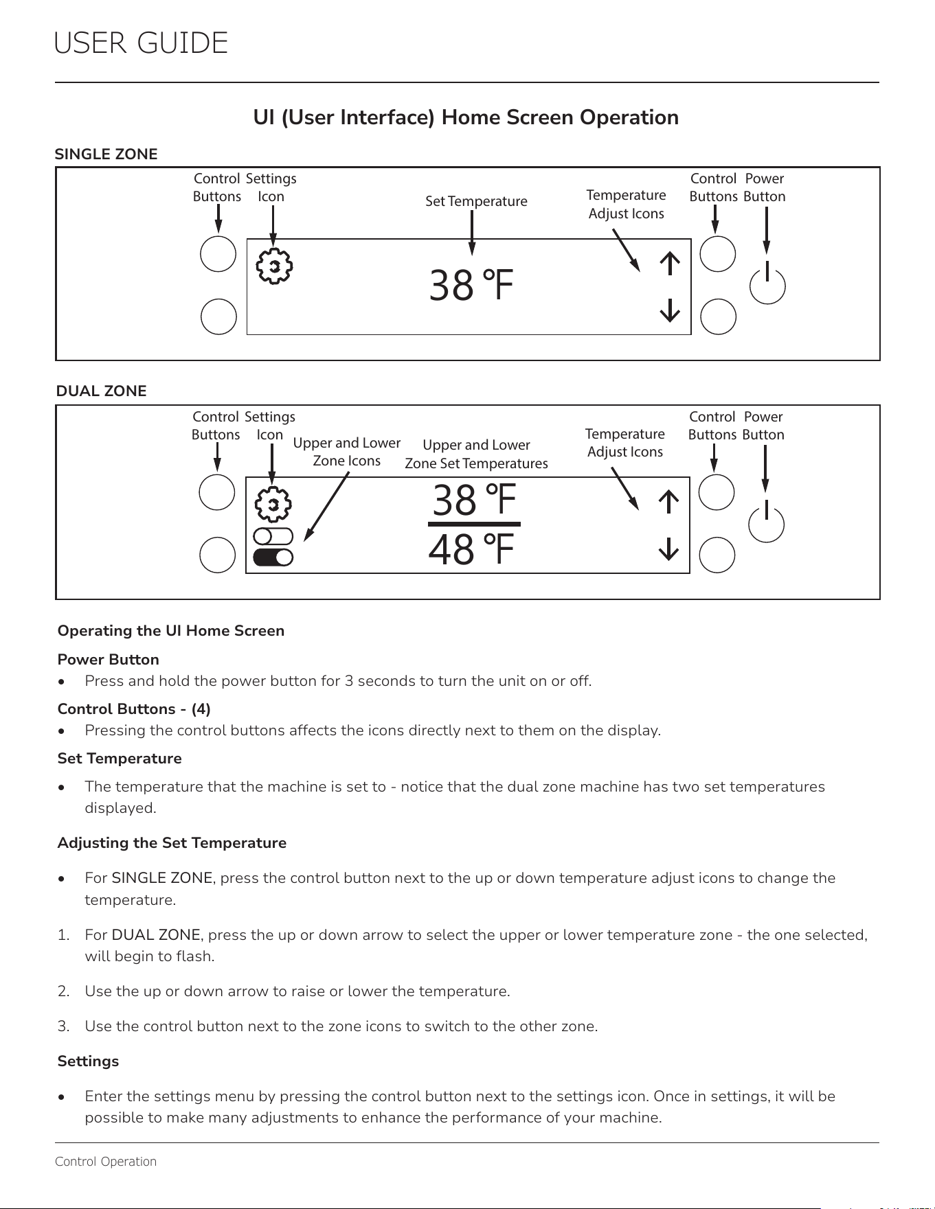
Operating the UI Home Screen
Power Button
• Press and hold the power button for 3 seconds to turn the unit on or off.
Control Buttons - (4)
• Pressing the control buttons affects the icons directly next to them on the display.
Set Temperature
• The temperature that the machine is set to - notice that the dual zone machine has two set temperatures
displayed.
Adjusting the Set Temperature
• For SINGLE ZONE, press the control button next to the up or down temperature adjust icons to change the
temperature.
1. For DUAL ZONE, press the up or down arrow to select the upper or lower temperature zone - the one selected,
will begin to ash.
2. Use the up or down arrow to raise or lower the temperature.
3. Use the control button next to the zone icons to switch to the other zone.
Settings
• Enter the settings menu by pressing the control button next to the settings icon. Once in settings, it will be
possible to make many adjustments to enhance the performance of your machine.
38
F
Control
Buttons
Control
Buttons
Power
Button
Settings
Icon
Temperature
Adjust Icons
Set Temperature
18
USER GUIDE
Control Operation
UI (User Interface) Settings Operation
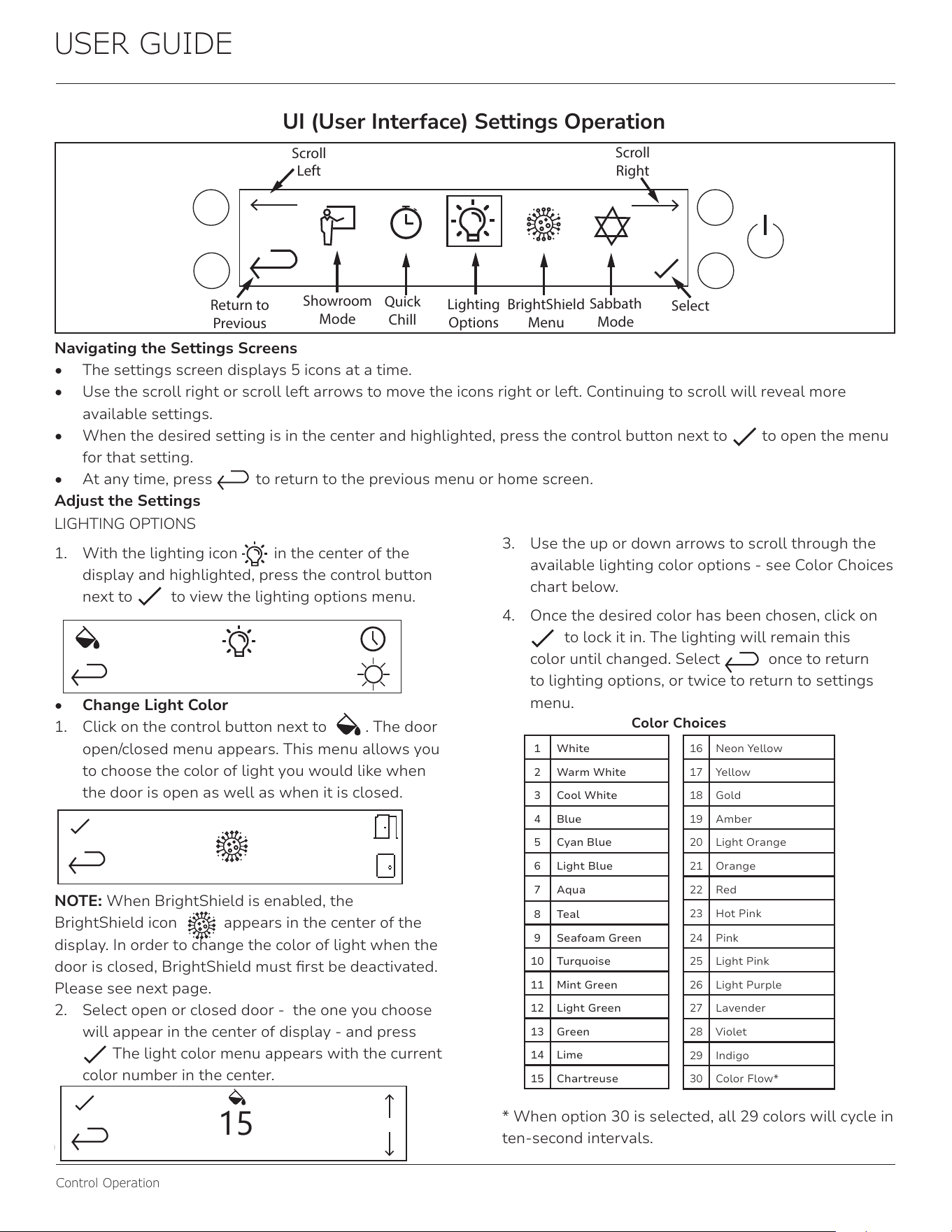
Navigating the Settings Screens
• The settings screen displays 5 icons at a time.
• Use the scroll right or scroll left arrows to move the icons right or left. Continuing to scroll will reveal more
available settings.
• When the desired setting is in the center and highlighted, press the control button next to to open the menu
for that setting.
• At any time, press to return to the previous menu or home screen.
Adjust the Settings
1 White
2 Warm White
3 Cool White
4 Blue
5 Cyan Blue
6 Light Blue
7 Aqua
8 Teal
9 Seafoam Green
10 Turquoise
11 Mint Green
12 Light Green
13 Green
14 Lime
15 Chartreuse
16 Neon Yellow
17 Yellow
18 Gold
19 Amber
20 Light Orange
21 Orange
22 Red
23 Hot Pink
24 Pink
25 Light Pink
26 Light Purple
27 Lavender
28 Violet
29 Indigo
30 Color Flow*
Quick
Chill
Lighting
Options
BrightShield
Menu
Showroom
Mode
Sabbath
Mode
Return to
Previous
Select
Scroll
Right
Scroll
Left
LIGHTING OPTIONS
1. With the lighting icon in the center of the
display and highlighted, press the control button
next to to view the lighting options menu.
• Change Light Color
1. Click on the control button next to . The door
open/closed menu appears. This menu allows you
to choose the color of light you would like when
the door is open as well as when it is closed.
NOTE: When BrightShield is enabled, the
BrightShield icon appears in the center of the
display. In order to change the color of light when the
door is closed, BrightShield must rst be deactivated.
Please see next page.
2. Select open or closed door - the one you choose
will appear in the center of display - and press
The light color menu appears with the current
color number in the center.
15
3. Use the up or down arrows to scroll through the
available lighting color options - see Color Choices
chart below.
4. Once the desired color has been chosen, click on
to lock it in. The lighting will remain this
color until changed. Select once to return
to lighting options, or twice to return to settings
menu.
* When option 30 is selected, all 29 colors will cycle in
ten-second intervals.
Color Choices
19
USER GUIDE
Control Operation
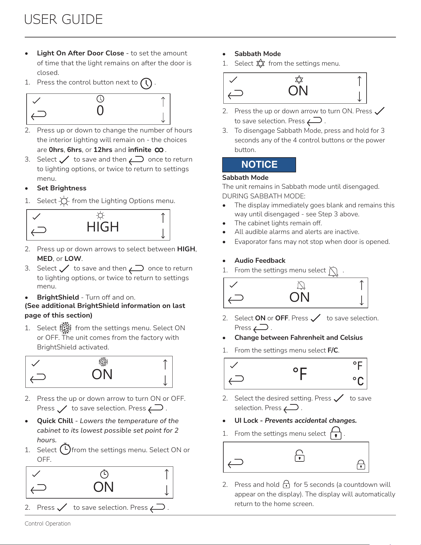
• Sabbath Mode
1. Select from the settings menu.
ON
2. Press the up or down arrow to turn ON. Press
to save selection. Press .
3. To disengage Sabbath Mode, press and hold for 3
seconds any of the 4 control buttons or the power
button.
NOTICE
Sabbath Mode
The unit remains in Sabbath mode until disengaged.
DURING SABBATH MODE:
• The display immediately goes blank and remains this
way until disengaged - see Step 3 above.
• The cabinet lights remain off.
• All audible alarms and alerts are inactive.
• Evaporator fans may not stop when door is opened.
• Audio Feedback
1. From the settings menu select .
ON
ON
2. Select ON or OFF. Press to save selection.
Press .
• Change between Fahrenheit and Celsius
1. From the settings menu select F/C.
°F
°F
°C
2. Select the desired setting. Press to save
selection. Press .
• UI Lock - Prevents accidental changes.
1. From the settings menu select .
2. Press and hold for 5 seconds (a countdown will
appear on the display). The display will automatically
return to the home screen.
• Light On After Door Close - to set the amount
of time that the light remains on after the door is
closed.
1. Press the control button next to .
0
2. Press up or down to change the number of hours
the interior lighting will remain on - the choices
are 0hrs, 6hrs, or 12hrs and innite
∞
.
3. Select to save and then once to return
to lighting options, or twice to return to settings
menu.
• Set Brightness
1. Select from the Lighting Options menu.
HIGH
2. Press up or down arrows to select between HIGH,
MED, or LOW.
3. Select to save and then once to return
to lighting options, or twice to return to settings
menu.
• BrightShield - Turn off and on.
(See additional BrightShield information on last
page of this section)
1. Select from the settings menu. Select ON
or OFF. The unit comes from the factory with
BrightShield activated.
ON
2. Press the up or down arrow to turn ON or OFF.
Press to save selection. Press .
• Quick Chill - Lowers the temperature of the
cabinet to its lowest possible set point for 2
hours.
1. Select
∞
from the settings menu. Select ON or
OFF.
ON
2. Press to save selection. Press .
20
USER GUIDE
Control Operation
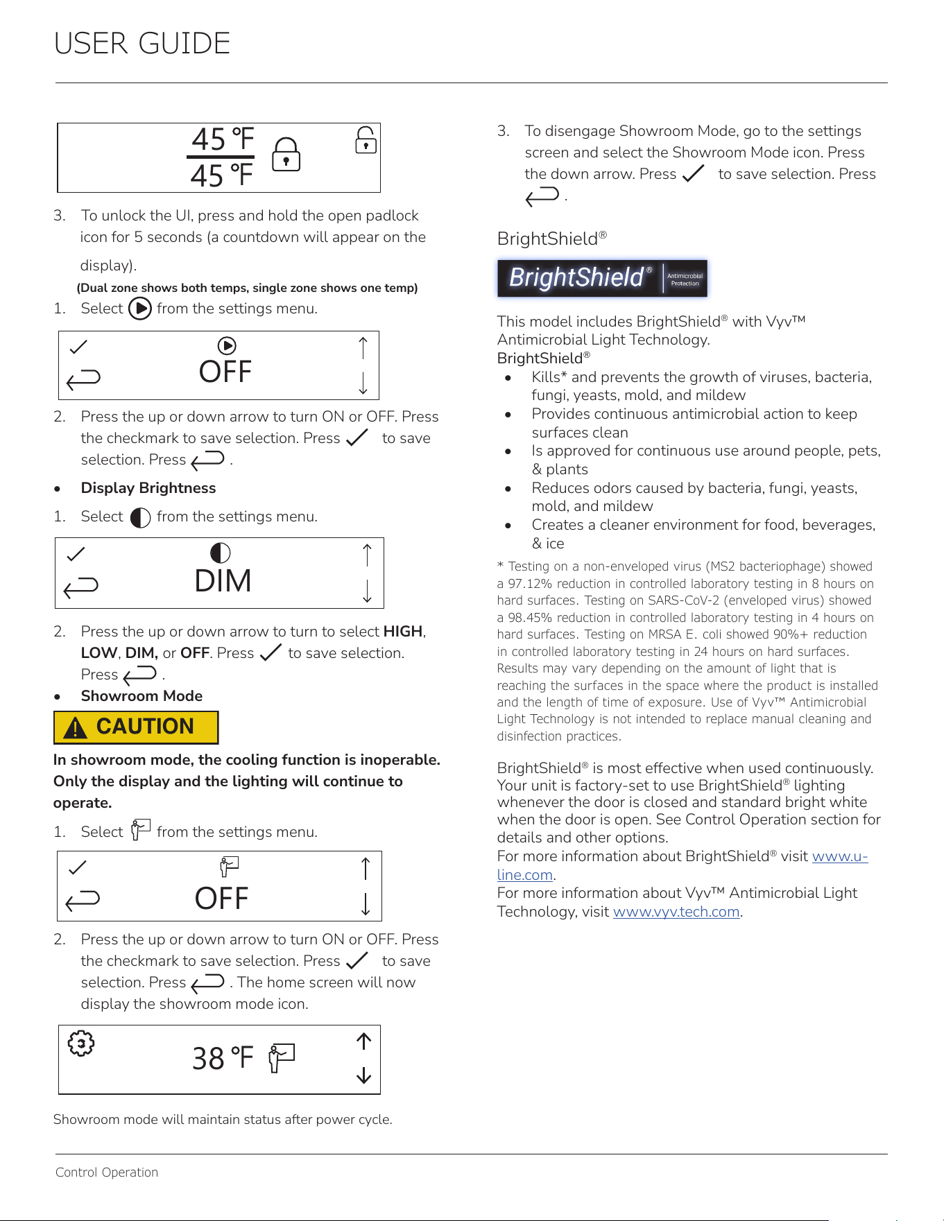
BrightShield
®
This model includes BrightShield
®
with Vyv™
Antimicrobial Light Technology.
BrightShield
®
• Kills* and prevents the growth of viruses, bacteria,
fungi, yeasts, mold, and mildew
• Provides continuous antimicrobial action to keep
surfaces clean
• Is approved for continuous use around people, pets,
& plants
• Reduces odors caused by bacteria, fungi, yeasts,
mold, and mildew
• Creates a cleaner environment for food, beverages,
& ice
BrightShield
®
is most effective when used continuously.
Your unit is factory-set to use BrightShield
®
lighting
whenever the door is closed and standard bright white
when the door is open. See Control Operation section for
details and other options.
For more information about BrightShield
®
visit www.u-
line.com.
For more information about Vyv™ Antimicrobial Light
Technology, visit www.vyv.tech.com.
* Testing on a non-enveloped virus (MS2 bacteriophage) showed
a 97.12% reduction in controlled laboratory testing in 8 hours on
hard surfaces. Testing on SARS-CoV-2 (enveloped virus) showed
a 98.45% reduction in controlled laboratory testing in 4 hours on
hard surfaces. Testing on MRSA E. coli showed 90%+ reduction
in controlled laboratory testing in 24 hours on hard surfaces.
Results may vary depending on the amount of light that is
reaching the surfaces in the space where the product is installed
and the length of time of exposure. Use of Vyv™ Antimicrobial
Light Technology is not intended to replace manual cleaning and
disinfection practices.
45
F
45
F
3. To unlock the UI, press and hold the open padlock
icon for 5 seconds (a countdown will appear on the
display).
(Dual zone shows both temps, single zone shows one temp)
1. Select from the settings menu.
45
OFF
2. Press the up or down arrow to turn ON or OFF. Press
the checkmark to save selection. Press to save
selection. Press .
• Display Brightness
1. Select from the settings menu.
DIM
2. Press the up or down arrow to turn to select HIGH,
LOW, DIM, or OFF. Press to save selection.
Press .
• Showroom Mode
CAUTION
!
In showroom mode, the cooling function is inoperable.
Only the display and the lighting will continue to
operate.
1. Select from the settings menu.
OFF
2. Press the up or down arrow to turn ON or OFF. Press
the checkmark to save selection. Press to save
selection. Press . The home screen will now
display the showroom mode icon.
38
F
Showroom mode will maintain status after power cycle.
3. To disengage Showroom Mode, go to the settings
screen and select the Showroom Mode icon. Press
the down arrow. Press to save selection. Press
.
21
USER GUIDE
Airow & Product Loading
Restricting airow may result in poor product
performance, product failure, and uneven internal
temperatures and may freeze contents.
• Do not block the front grille - no additional clearance
around sides, top or rear of unit is needed for ventilation
• Do not install behind a closed door
• When loading, leave space between internal fans, vents,
and side walls to allow air to circulate freely
NOTICE
AIRFLOW
External
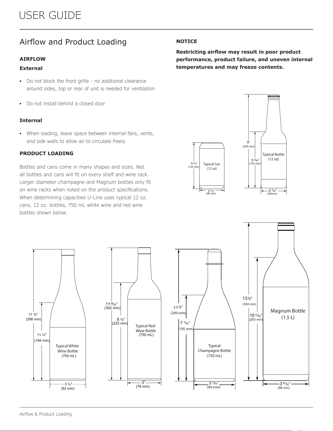
PRODUCT LOADING
Bottles and cans come in many shapes and sizes. Not
all bottles and cans will t on every shelf and wine rack.
Larger diameter champagne and Magnum bottles only t
on wine racks when noted on the product specications.
When determining capacities U-Line uses typical 12 oz.
cans, 12 oz. bottles, 750 mL white wine and red wine
bottles shown below.
Airow and Product Loading
Typical Can
(12 oz)
4
(123 mm)
(66 mm)
2
27⁄32”
19⁄32”
Typical Bottle
(12 oz)
9”
5
2
7⁄16”
5⁄16”
(135 mm)
(64mm)
(229 mm)
Typical White
Wine Bottle
11
(298 mm)
(750 mL)
3
¾”
(184 mm)
(82 mm)
11
¼”
¼”
Typical Red
Wine Bottle
11
(302 mm)
8
3”
29⁄32”
¾”
(222 mm)
(750 mL)
(76 mm)
Typical
Champagne Bottle
(750 mL)
3 11⁄16”
7
¾”
11⁄16”
(299 mm)
(94 mm)
(195 mm)
11
Magnum Bottle
(1.5 L)
13
10
3
1⁄8”
(334 mm)
11⁄32”
(263 mm)
27⁄32”
(98 mm)
Internal
22
USER GUIDE
Cleaning
Cleaning
Stainless Models
Stainless door panels and handles can discolor when
exposed to chlorine gas, pool chemicals, saltwater or
cleaners with bleach.
Keep your stainless unit looking new by cleaning with a
good quality all-in-one stainless steel cleaner and polish
monthly. For best results use Claire
®
Stainless Steel
Polish and Cleaner. Comparable products are acceptable.
Frequent cleaning will remove surface contamination that
could lead to rust. Some installations may require cleaning
weekly.
Do not clean with steel wool pads.
Do not use stainless steel cleaners or polishes on
any glass surfaces.
Clean any glass surfaces with a non-chlorine glass
cleaner.
Do not use cleaners not specifically intended for
stainless steel on stainless steel surfaces (this
includes glass, tile and counter cleaners).
If any surface discoloring or rusting appears, clean it
quickly with Bon-Ami
®
or Barkeepers Friend Cleanser
®
and a nonabrasive cloth. Always clean with the grain.
Always finish with Claire
®
Stainless Steel Polish and
Cleaner or comparable product to prevent further
problems.
Using abrasive pads such as Scotchbrite™ will
cause the graining in the stainless steel to
become blurred.
Rust not cleaned up promptly can penetrate the
surface of the stainless steel and complete
removal of the rust may not be possible.
Integrated Models
To clean integrated panels, use household cleaner per the
cabinet manufacturer’s recommendation.
INTERIOR CLEANING
Disconnect power to the unit.
Clean the interior and all removed components using a
mild nonabrasive detergent and warm water solution
applied with a soft sponge or non-abrasive cloth.
Rinse the interior using a soft sponge and clean water.
Do not use any solvent-based or abrasive
cleaners. These types of cleaners may transfer taste to
the interior products and damage or discolor the lining.
DEFROSTING
Under normal conditions this unit does not require manual
defrosting. Minor frost on the rear wall or visible through
the evaporator plate vents is normal and will melt during
each off cycle.
If there is excessive build-up of 1/4" (6 mm) or more,
manually defrost the unit.
Ensure the door is closing and sealing properly.
High ambient temperature and excessive humidity can
also produce frost.
CAUTION
!
DO NOT use an ice pick or other sharp
instrument to help speed up defrosting. These
instruments can puncture the inner lining or
damage the cooling unit. DO NOT use any type of
heater to defrost. Using a heater to speed up
defrosting can cause personal injury and
damage to the inner lining.
23
USER GUIDE
Cleaning
NOTICE
The drain pan was not designed to capture the
water created when manually defrosting. To
prevent water from overflowing the drain pan
and possibly damaging water sensitive flooring,
the unit must be removed from cabinetry.
To defrost:
1. Disconnect power to the unit.
2. Remove all products from the interior.
3. Prop the door in an open position (2 in. [50 mm]
minimum).
4. Allow the frost to melt naturally.
5. After the frost melts completely clean the interior and
all removed components. (See INTERIOR CLEANING).
6. When the interior is dry, reconnect power and turn unit
on.
24
USER GUIDE
Grille Installation
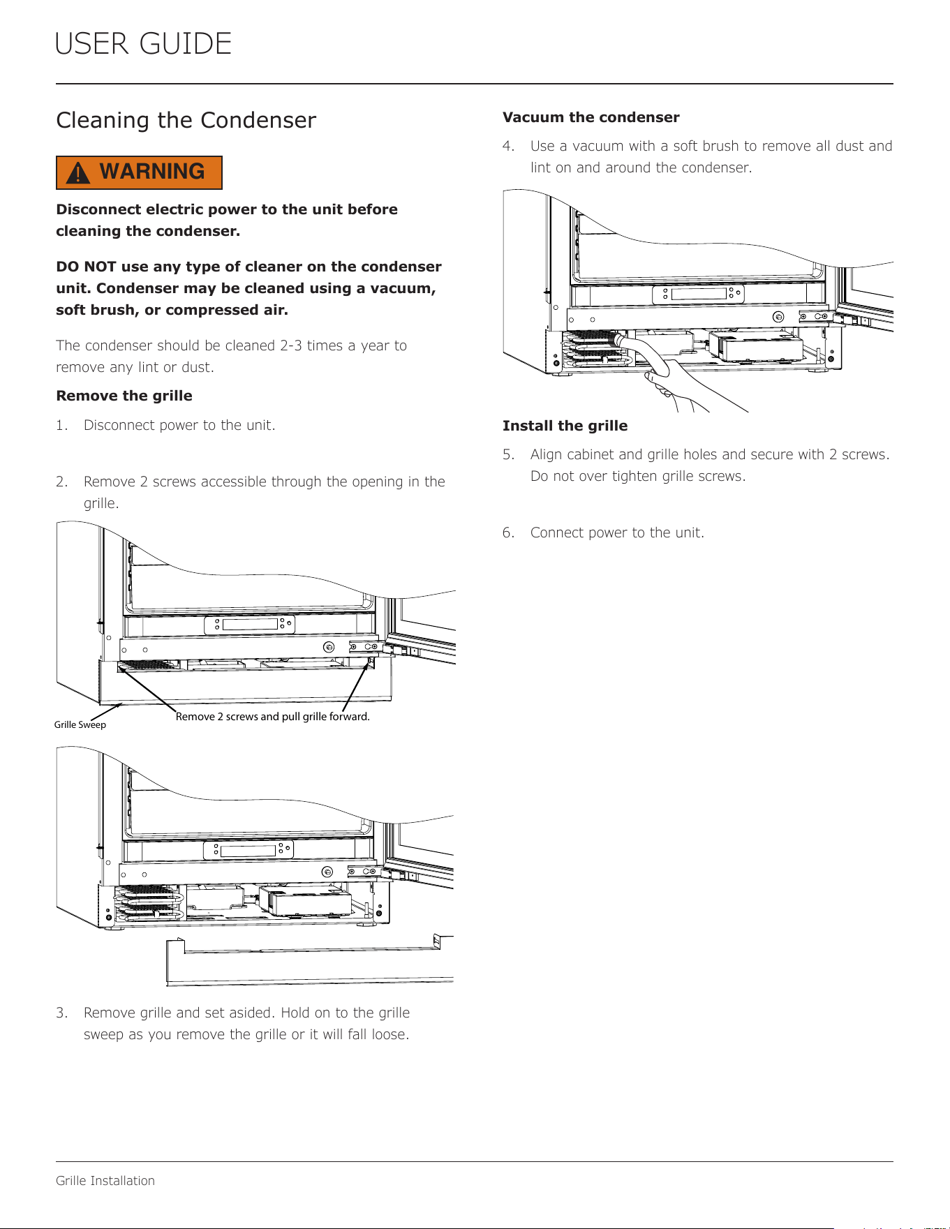
Cleaning the Condenser
Disconnect electric power to the unit before
cleaning the condenser.
DO NOT use any type of cleaner on the condenser
unit. Condenser may be cleaned using a vacuum,
soft brush, or compressed air.
The condenser should be cleaned 2-3 times a year to
remove any lint or dust.
Remove the grille
1. Disconnect power to the unit.
2. Remove 2 screws accessible through the opening in the
grille.
3. Remove grille and set asided. Hold on to the grille
sweep as you remove the grille or it will fall loose.
Vacuum the condenser
4. Use a vacuum with a soft brush to remove all dust and
lint on and around the condenser.
Install the grille
5. Align cabinet and grille holes and secure with 2 screws.
Do not over tighten grille screws.
6. Connect power to the unit.
WARNING
!
Remove 2 screws and pull grille forward.
Grille Sweep
25
USER GUIDE
Extended Non-Use
Extended Non-Use
VACATION/HOLIDAY, PROLONGED SHUTDOWN
The following steps are recommended for periods of
extended non-use:
1. Remove all consumable content from the unit.
2. Disconnect the power cord from its outlet/socket and
leave it disconnected until the unit is returned to
service.
3. If ice is on the evaporator, allow ice to thaw naturally.
4. Clean and dry the interior of the unit. Ensure all water
has been removed from the unit.
5. The door must remain open to prevent formation of
mold and mildew. Open door a minimum of 2"
(50 mm) to provide the necessary ventilation.
WINTERIZATION
If the unit will be exposed to temperatures of 40°F (5°C)
or less, the steps above must be followed.
For questions regarding winterization, please
call U-Line at 414.354.0300.
CAUTION
!
Damage caused by freezing temperatures is not
covered by the warranty.
26
USER GUIDE
Troubleshooting
If you think your U-Line product is malfunctioning, read the
CONTROL OPERATION section to clearly understand the
function of the control.
If the problem persists, read the NORMAL OPERATING
SOUNDS and TROUBLESHOOTING GUIDE sections below
to help you quickly identify common problems and possible
causes and remedies. Most often, this will resolve the
problem without the need to call for service.
If you do not understand a troubleshooting remedy, or your
product needs service, contact U-Line Corporation directly
at +1.616.754.5601.
When you call, you will need your product Model and Serial
Numbers. This information appears on the Model and Serial
number plate located on the upper right or rear wall of the
interior of your product.
All models incorporate rigid foam insulated cabinets to
provide high thermal eciency and maximum sound
reduction for its internal working components. Despite this
technology, your model may make sounds that are
unfamiliar.
Normal operating sounds may be more noticeable because
of the unit’s environment. Hard surfaces such as cabinets,
wood, vinyl or tiled oors and paneled walls have a
tendency to reect normal appliance operating noises.
Listed below are common refrigeration components with a
brief description of the normal operating sounds they
make. NOTE: Your product may not contain all the
components listed.
• Compressor: The compressor makes a hum or pulsing
sound that may be heard when it operates.
BEFORE CALLING FOR SERVICE
TROUBLESHOOTING GUIDE
ELECTROCUTION HAZARD. Never attempt to
repair or perform maintenance on the unit
before disconnecting the main electrical power.
Troubleshooting - What to check when problems occur:
NORMAL OPERATING SOUNDS
IF SERVICE IS REQUIRED
Troubleshooting
• Evaporator: Refrigerant owing through an evaporator
may sound like boiling liquid.
• Condenser Fan: Air moving through a condenser may
be heard.
• Automatic Defrost Drain Pan: Water may be heard
dripping or running into the drain pan when the unit is
in the defrost cycle.
DANGER
!
Problem Possible Cause and Remedy
Interior Light
Does Not
Illuminate
If the unit is cooling, it may be in
Sabbath mode.
Light Remains
on When Door
Is Closed.
Turn o light switch if equipped.
Adjust light actuator bracket on bottom
of door.
Unit Develops
Frost on
Internal
Surfaces.
Ensure the door is closing and sealing
properly.
Unit Develops
Condensation
on External
Surfaces.
The unit is exposed to excessive
humidity. Moisture will dissipate as
humidity levels decrease.
Product is Not
Cold Enough
Air temperature does not indicate
product temperature. See CHECKING
PRODUCT TEMPERATURE below.
Adjust the temperature to a cooler set
point.
Ensure unit is not located in excessive
ambient temperatures or in direct
sunlight.
Ensure the door is closing and sealing
properly.
Ensure the interior light has not
remained on too long.
Ensure nothing is blocking the front
grille, found at the bottom of the unit.
Ensure the condenser coil is clean and
free of any dirt or lint build-up.
27
USER GUIDE
Troubleshooting
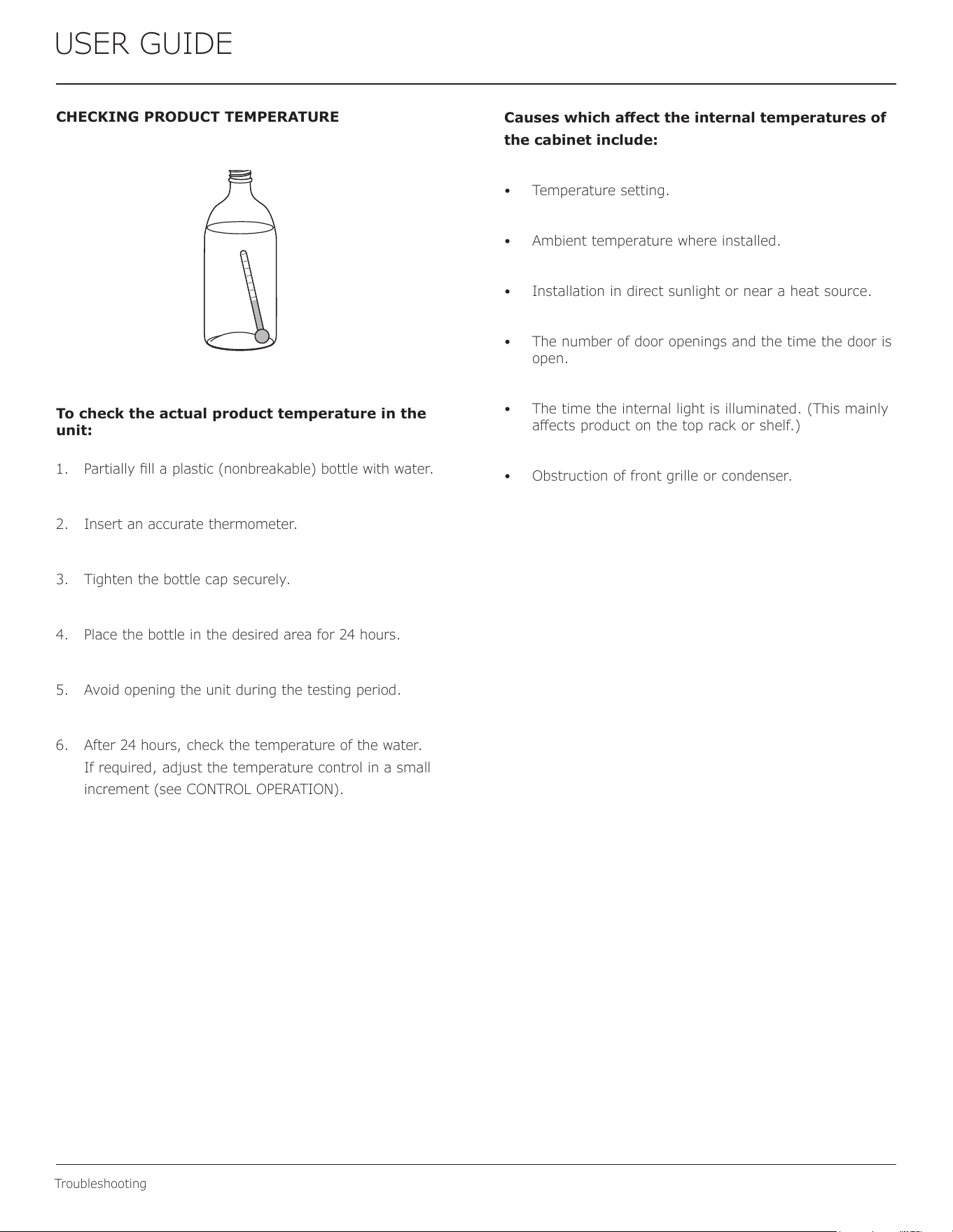
CHECKING PRODUCT TEMPERATURE
To check the actual product temperature in the
unit:
1. Partially ll a plastic (nonbreakable) bottle with water.
2. Insert an accurate thermometer.
3. Tighten the bottle cap securely.
4. Place the bottle in the desired area for 24 hours.
5. Avoid opening the unit during the testing period.
6. After 24 hours, check the temperature of the water.
If required, adjust the temperature control in a small
increment (see CONTROL OPERATION).
Causes which aect the internal temperatures of
the cabinet include:
• Temperature setting.
• Ambient temperature where installed.
• Installation in direct sunlight or near a heat source.
• The number of door openings and the time the door is
open.
• The time the internal light is illuminated. (This mainly
aects product on the top rack or shelf.)
• Obstruction of front grille or condenser.
28
USER GUIDE
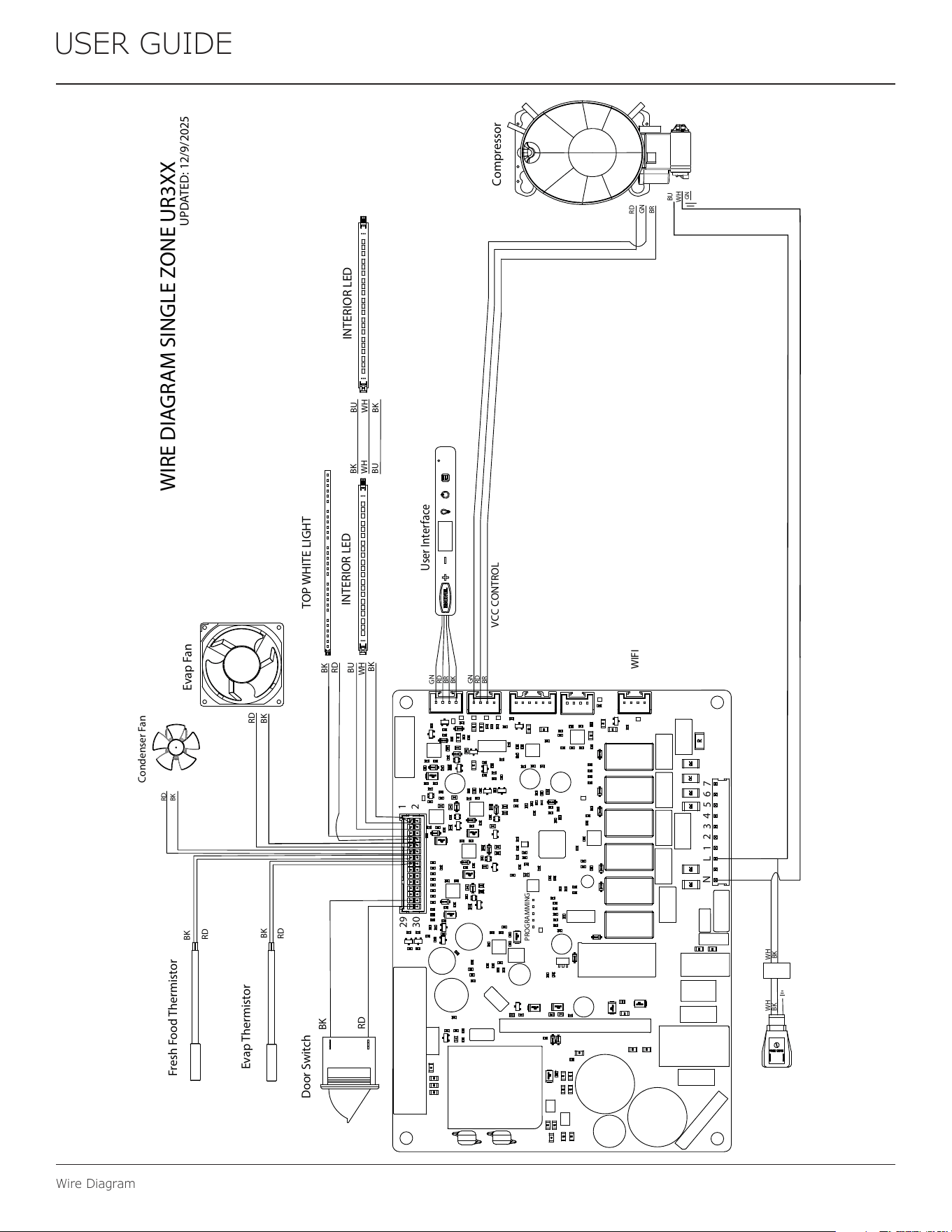
Wire Diagram
WIRE DIAGRAM SINGLE ZONE UR3XX
Evap Fan
User Interface
Door Switch
Evap Thermistor
Fresh Food Thermistor
RD
BK
BU
BK
RD
BK
RD
RD
BK
WH WH
BK
BK
Condenser Fan
RD
BK
TOP WHITE LIGHT
UPDATED: 12/9/2025
Compressor
BU
WH
GN
BK
BK
WH
RD
1
2
29
30
N
L
1
2
3
4
5
6
7
VCC CONTROL
WIFI
PROGRAMMING
INTERIOR LED
INTERIOR LED
BK
WH
BU
BU
WH
BK
GN
RD
BR
BK
GN
RD
BR
GN
BR
RD
29
USER GUIDE
Product Liability
Product Liability
Field service technicians are authorized to make an initial
assessment in the event of reported damages. If there are
any questions about the process involved, the technician
should call U-Line for further explanation.
While inspecting for defects or installation issues, photos
should be taken to document any damages or issues found.
During the assessment, if the service technician is able to
nd the source of the damage and it can be resolved by
replacement of a part, the servicer is authorized to replace
the part in question. The part that caused the damage
must be returned to U-Line in its entirety. The part must
be clearly labeled with the serial number of the unit it was
removed from, the date, and the servicer who removed the
part.
If the service technician determines the damage is the
result of installation issues (water connection/drain, etc.),
the consumer would be notied and the issues shall be
resolved at the direction of the consumer.
If damage is evident and the service technician is
unable to nd the source, U-Line must be contacted at
+1.414.354.0300 for further direction.
8900 N. 55th Street • Milwaukee, WI 53223
T: +1.414.354.0300 • F: +1.414.354.5696
Website: www.u-line.com
Right product. Right place.
Right temperature Since 1962.
30
USER GUIDE
R-600A Specications
USER GUIDE
R-600A Specifications 1
u-line.com
SAFETY • INSTALLATION & INTEGRATION • OPERATING INSTRUCTIONS • MAINTENANCE • SERVICE
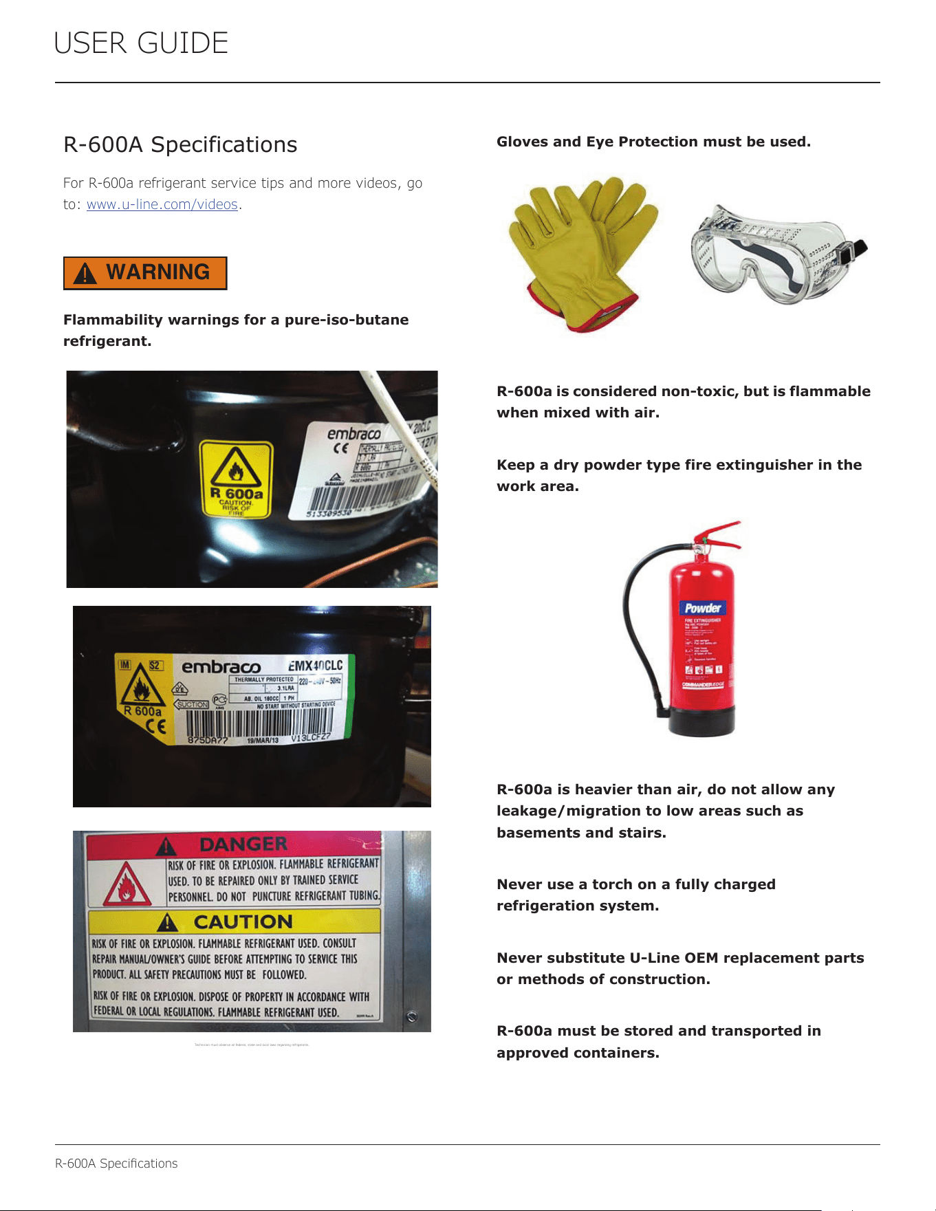
R-600A Specifications
For R-600a refrigerant service tips and more videos, go
to: www.u-line.com/videos
.
WARNING
!
Flammability warnings for a pure-iso-butane
refrigerant.
Technician m ust observe al l federal, s tate and local la ws regardi ng refrigera nts.
Gloves and Eye Protection must be used.
R-600a is considered non-toxic, but is flammable
when mixed with air.
Keep a dry powder type fire extinguisher in the
work area.
R-600a is heavier than air, do not allow any
leakage/migration to low areas such as
basements and stairs.
Never use a torch on a fully charged
refrigeration system.
Never substitute U-Line OEM replacement parts
or methods of construction.
R-600a must be stored and transported in
approved containers.
31
R-600A Specications
USER GUIDE
USER GUIDE
R-600A Specifications 2
u-line.com
SAFETY • INSTALLATION & INTEGRATION • OPERATING INSTRUCTIONS • MAINTENANCE • SERVICE
WARNING
!
Only skilled and well trained service technicians
permitted to service R-600a equipped products.
All tools and equipment must be approved for
use with R-600a refrigerant.
Local, state and federal laws, standards must be
observed along with proper certification and
licensing.
Ventilation is required during servicing.
No conversions to R-600a from any other
refrigerants. OEM R-600a equipped unit only.
Service area must be free of ignition sources.
No smoking is allowed in the service area.
All replacement electrical components must be
OEM and installed properly (sealed and
covered).
If the evaporator is cold prior to service, it must
be thawed prior to service.
When using a vacuum pump, start pump before
opening refrigeration system.
Vacuum pump and recovery equipment should
be at least 10 feet from the work area.
It is recommended that a simple LPG gas
detector is on site during service.
Ensure that all R-600a is removed from the
system prior to brazing any part of the sealed
system.
Only a clean, dry leak free system should be
charged with R-600a.
R-600A SPECIFICATIONS/LABELING
R-600a equipped products are labeled (both the unit and
the compressor).
R-600a is colorless and odorless.
R-600a is considered non-toxic, but is flammable when
mixed with air.
Do not remove or alter any R-600a labeling on the
product.
Use only a refrigerant grade R-600a from a properly
labeled container.
RECOVERING/RECLAIMING R-600A
(R-600a has been exempted from recovery/reclaiming
requirements by the US EPA)
Recovery/Reclaiming equipment must be approved for use
with R-600a.
Ensure the evaporator is at room temperature prior to
recovery/reclaiming R-600a.
Use a common piercing pliers or piercing valve to remove
R-600a from the compressor process tube. (Note: Piercing
devices must not be left on the system and must be
replaced with a Schrader type valve.)
32
USER GUIDE
R-600A Specications
USER GUIDE
R-600A Specifications 3
u-line.com
SAFETY • INSTALLATION & INTEGRATION • OPERATING INSTRUCTIONS • MAINTENANCE • SERVICE
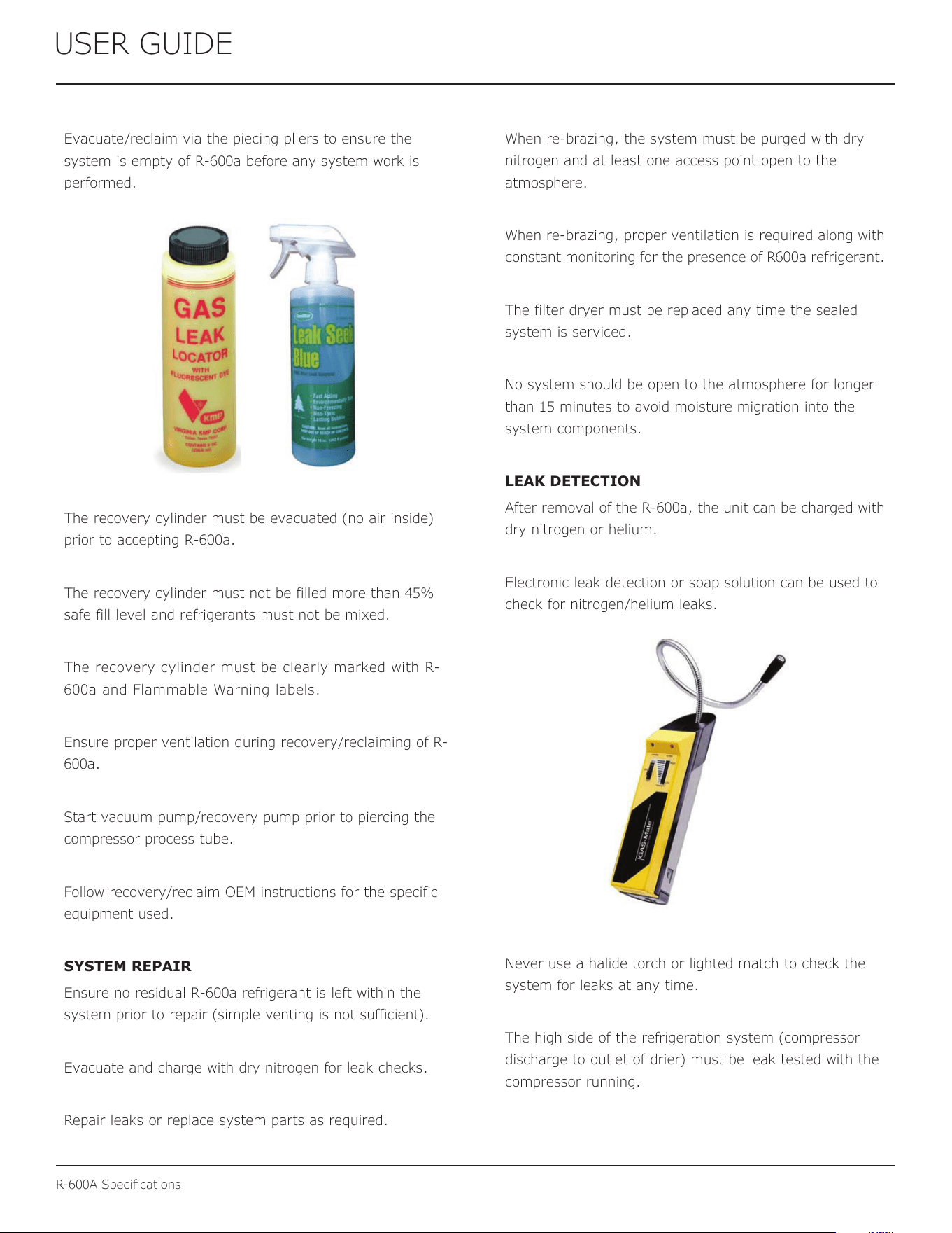
Evacuate/reclaim via the piecing pliers to ensure the
system is empty of R-600a before any system work is
performed.
The recovery cylinder must be evacuated (no air inside)
prior to accepting R-600a.
The recovery cylinder must not be filled more than 45%
safe fill level and refrigerants must not be mixed.
The recovery cylinder must be clearly marked with R-
600a and Flammable Warning labels.
Ensure proper ventilation during recovery/reclaiming of R-
600a.
Start vacuum pump/recovery pump prior to piercing the
compressor process tube.
Follow recovery/reclaim OEM instructions for the specific
equipment used.
SYSTEM REPAIR
Ensure no residual R-600a refrigerant is left within the
system prior to repair (simple venting is not sufficient).
Evacuate and charge with dry nitrogen for leak checks.
Repair leaks or replace system parts as required.
When re-brazing, the system must be purged with dry
nitrogen and at least one access point open to the
atmosphere.
When re-brazing, proper ventilation is required along with
constant monitoring for the presence of R600a refrigerant.
The filter dryer must be replaced any time the sealed
system is serviced.
No system should be open to the atmosphere for longer
than 15 minutes to avoid moisture migration into the
system components.
LEAK DETECTION
After removal of the R-600a, the unit can be charged with
dry nitrogen or helium.
Electronic leak detection or soap solution can be used to
check for nitrogen/helium leaks.
Never use a halide torch or lighted match to check the
system for leaks at any time.
The high side of the refrigeration system (compressor
discharge to outlet of drier) must be leak tested with the
compressor running.
33
R-600A Specications
USER GUIDE
USER GUIDE
R-600A Specifications 4
u-line.com
SAFETY • INSTALLATION & INTEGRATION • OPERATING INSTRUCTIONS • MAINTENANCE • SERVICE
The low side of the refrigeration system (evaporator,
compressor and suction line) must be leak tested with the
compressor off (equalized pressure).
RECHARGING
No air is ever to be allowed inside the refrigeration system
(R-600a refrigerant or dry nitrogen only).
Never use a torch on a fully charged refrigeration system.
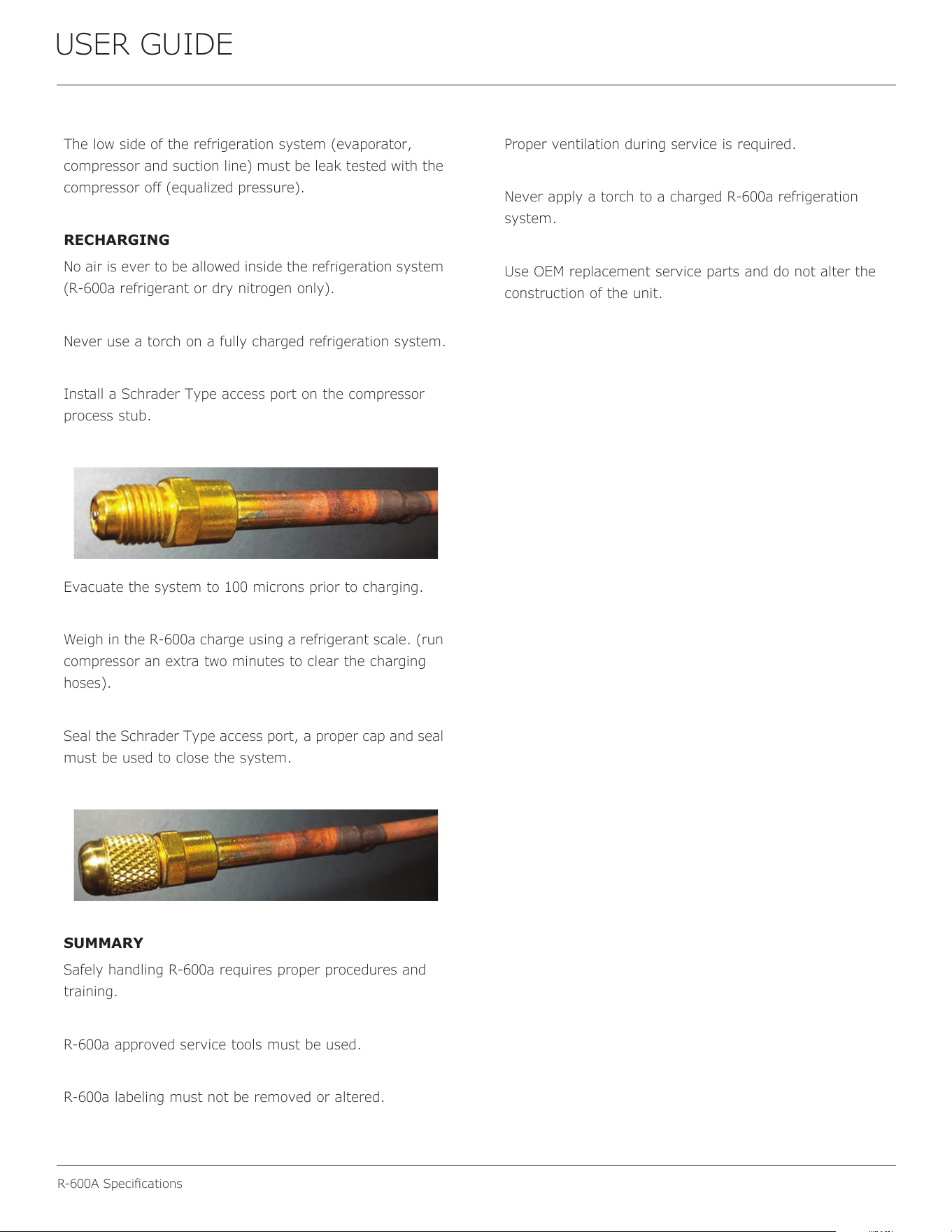
Install a Schrader Type access port on the compressor
process stub.
Evacuate the system to 100 microns prior to charging.
Weigh in the R-600a charge using a refrigerant scale. (run
compressor an extra two minutes to clear the charging
hoses).
Seal the Schrader Type access port, a proper cap and seal
must be used to close the system.
SUMMARY
Safely handling R-600a requires proper procedures and
training.
R-600a approved service tools must be used.
R-600a labeling must not be removed or altered.
Proper ventilation during service is required.
Never apply a torch to a charged R-600a refrigeration
system.
Use OEM replacement service parts and do not alter the
construction of the unit.
34
USER GUIDE
System Diagnosis Guide
System Diagnosis Guide
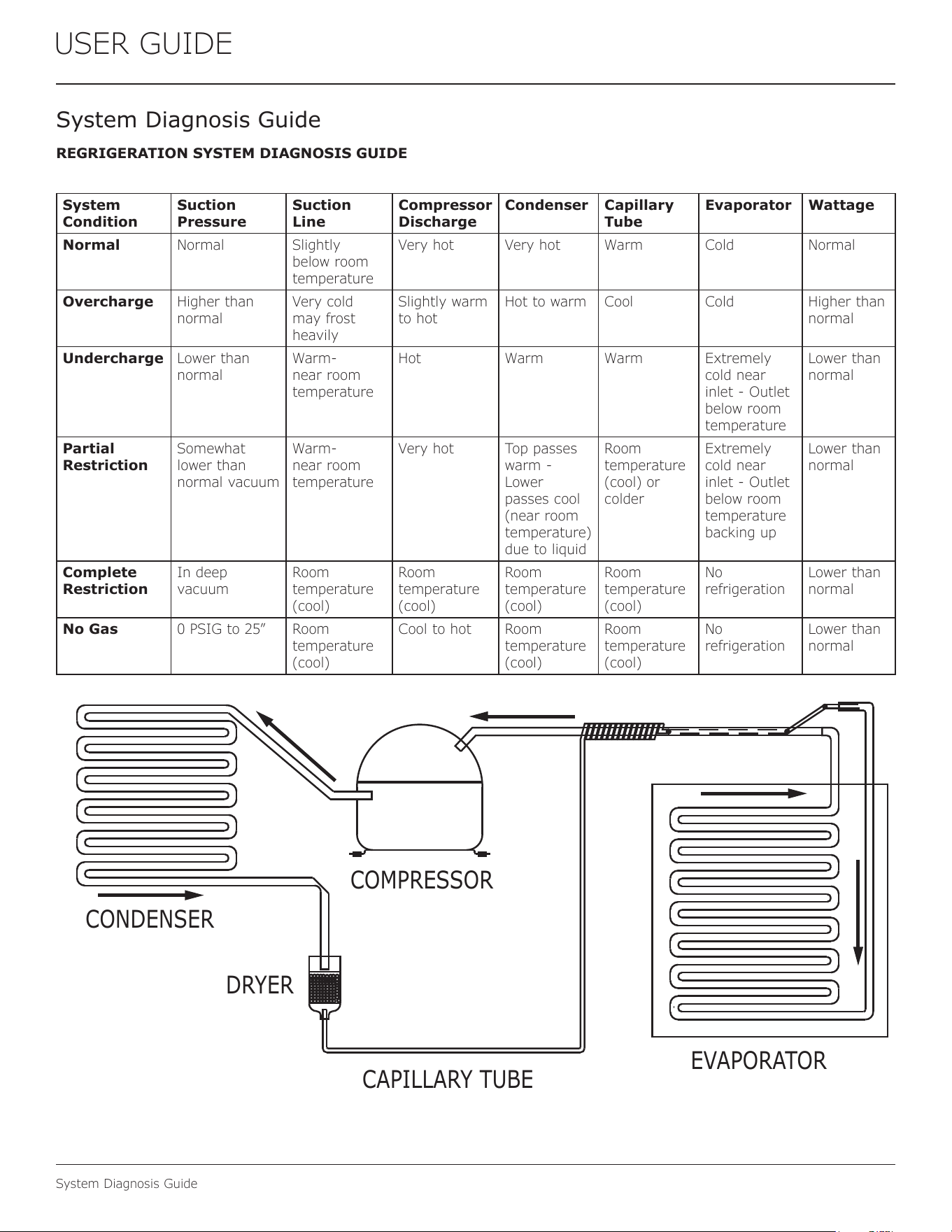
REGRIGERATION SYSTEM DIAGNOSIS GUIDE
System
Condition
Suction
Pressure
Suction
Line
Compressor
Discharge
Condenser Capillary
Tube
Evaporator Wattage
Normal Normal Slightly
below room
temperature
Very hot Very hot Warm Cold Normal
Overcharge Higher than
normal
Very cold
may frost
heavily
Slightly warm
to hot
Hot to warm Cool Cold Higher than
normal
Undercharge Lower than
normal
Warm-
near room
temperature
Hot Warm Warm Extremely
cold near
inlet - Outlet
below room
temperature
Lower than
normal
Partial
Restriction
Somewhat
lower than
normal vacuum
Warm-
near room
temperature
Very hot Top passes
warm -
Lower
passes cool
(near room
temperature)
due to liquid
Room
temperature
(cool) or
colder
Extremely
cold near
inlet - Outlet
below room
temperature
backing up
Lower than
normal
Complete
Restriction
In deep
vacuum
Room
temperature
(cool)
Room
temperature
(cool)
Room
temperature
(cool)
Room
temperature
(cool)
No
refrigeration
Lower than
normal
No Gas 0 PSIG to 25” Room
temperature
(cool)
Cool to hot Room
temperature
(cool)
Room
temperature
(cool)
No
refrigeration
Lower than
normal
CAPILLARY TUBE
DRYER
CONDENSER
COMPRESSOR
EVAPORATOR
35
USER GUIDE
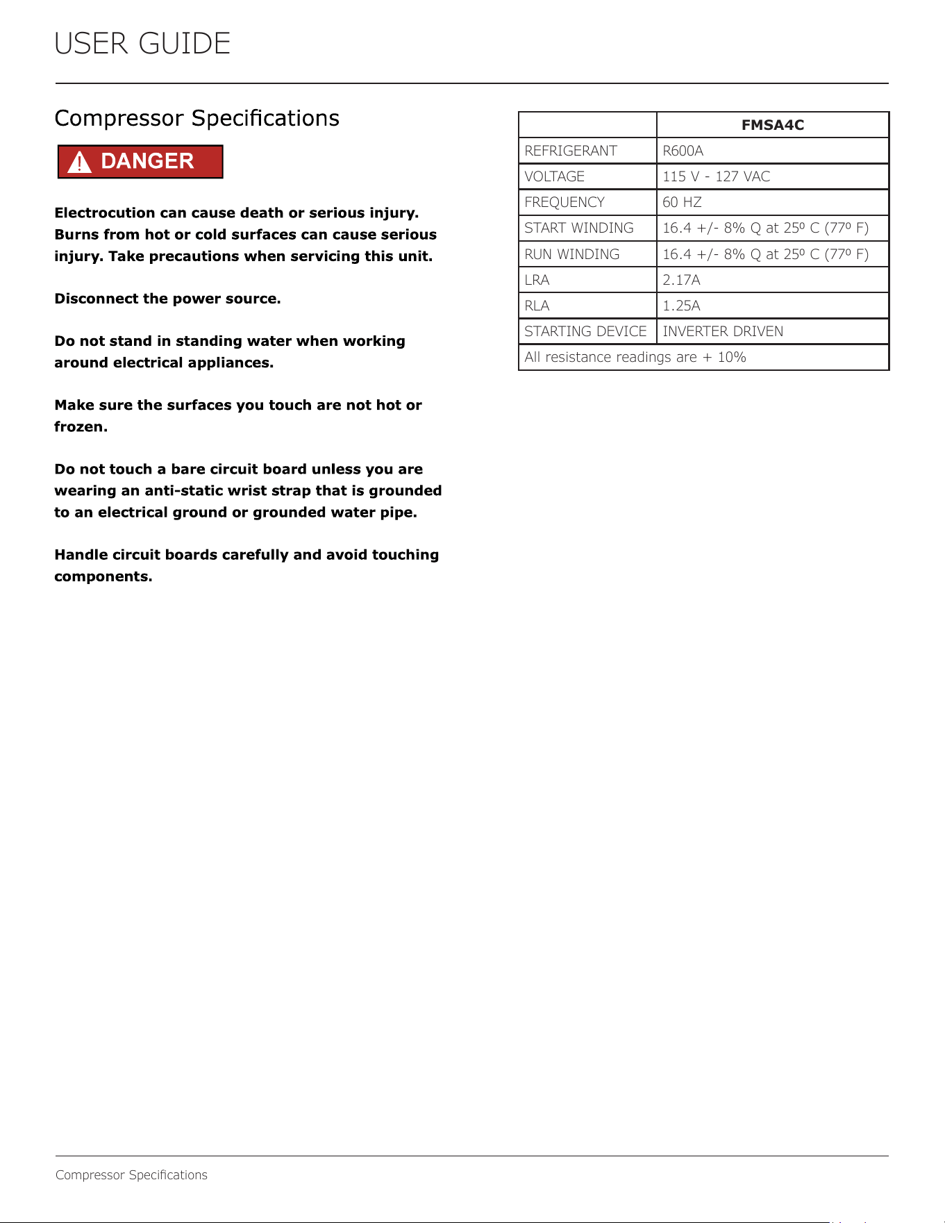
Compressor Specications
FMSA4C
REFRIGERANT R600A
VOLTAGE 115 V - 127 VAC
FREQUENCY 60 HZ
START WINDING 16.4 +/- 8% Q at 250 C (770 F)
RUN WINDING 16.4 +/- 8% Q at 250 C (770 F)
LRA 2.17A
RLA 1.25A
STARTING DEVICE INVERTER DRIVEN
All resistance readings are + 10%
36
USER GUIDE
Troubleshooting Extended
Troubleshooting - Extended
CAUTION
!
Never attempt to repair or perform maintenance
on the unit until the main electrical power has
been disconnected from the unit.
SPECIFIC ERRORS AND ISSUES
The advanced diagnostic capabilities of the electronic
controls utilized on the 1, 3, and 5 Class units allow for
easy and thorough troubleshooting.
Navigation of the control is the key and is explained in
the CONTROL OPERATION section of the manual, along
with control button layout, control function descriptions,
a service mode menu and service menu selection
explanations.
Verication of temperature and thermistor performance can
be identied by directly viewing thermistor readings in the
service mode.
Included in this section are some diagnostic tips and of
course, if additional help is required, please contact the U-
Line Corp, “Customer Care Facility” at +1.414.354.0300 for
assistance.
NORMAL OPERATING SOUNDS
All models incorporate rigid foam insulated cabinets to
provide high thermal eciency and maximum sound
reduction for its internal working components. Despite
this technology, your model may make sounds that are
unfamiliar.
Normal operating sounds may be more noticeable because
of the unit’s environment. Hard surfaces such as cabinets,
wood, vinyl or tiled oors and paneled walls have a
tendency to reect normal appliance operating noises.
Listed below are common refrigeration components with a
brief description of the normal sounds they make. NOTE:
Your product may not contain all the components listed.
• Compressor: The compressor makes a hum or pulsing
sound that may be heard when it operates.
• Evaporator: Refrigerant owing through an evaporator
may sound like boiling liquid.
• Condenser Fan: Air moving through a condenser may
be heard.
• Automatic Defrost Drain Pan: Water may be heard
dripping or running into the drain pan when the unit is
in the defrost cycle.
Solenoid Valves: An occasional clicking sound may be
heard as solenoid valves are operated.
37
USER GUIDE
Troubleshooting Extended
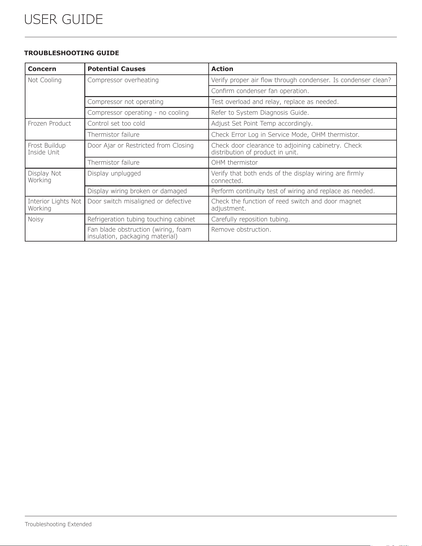
TROUBLESHOOTING GUIDE
Concern Potential Causes Action
Not Cooling Compressor overheating Verify proper air ow through condenser. Is condenser clean?
Conrm condenser fan operation.
Compressor not operating Test overload and relay, replace as needed.
Compressor operating - no cooling Refer to System Diagnosis Guide.
Frozen Product Control set too cold Adjust Set Point Temp accordingly.
Thermistor failure Check Error Log in Service Mode, OHM thermistor.
Frost Buildup
Inside Unit
Door Ajar or Restricted from Closing Check door clearance to adjoining cabinetry. Check
distribution of product in unit.
Thermistor failure OHM thermistor
Display Not
Working
Display unplugged Verify that both ends of the display wiring are rmly
connected.
Display wiring broken or damaged Perform continuity test of wiring and replace as needed.
Interior Lights Not
Working
Door switch misaligned or defective Check the function of reed switch and door magnet
adjustment.
Noisy Refrigeration tubing touching cabinet Carefully reposition tubing.
Fan blade obstruction (wiring, foam
insulation, packaging material)
Remove obstruction.
38
USER GUIDE
Troubleshooting Extended
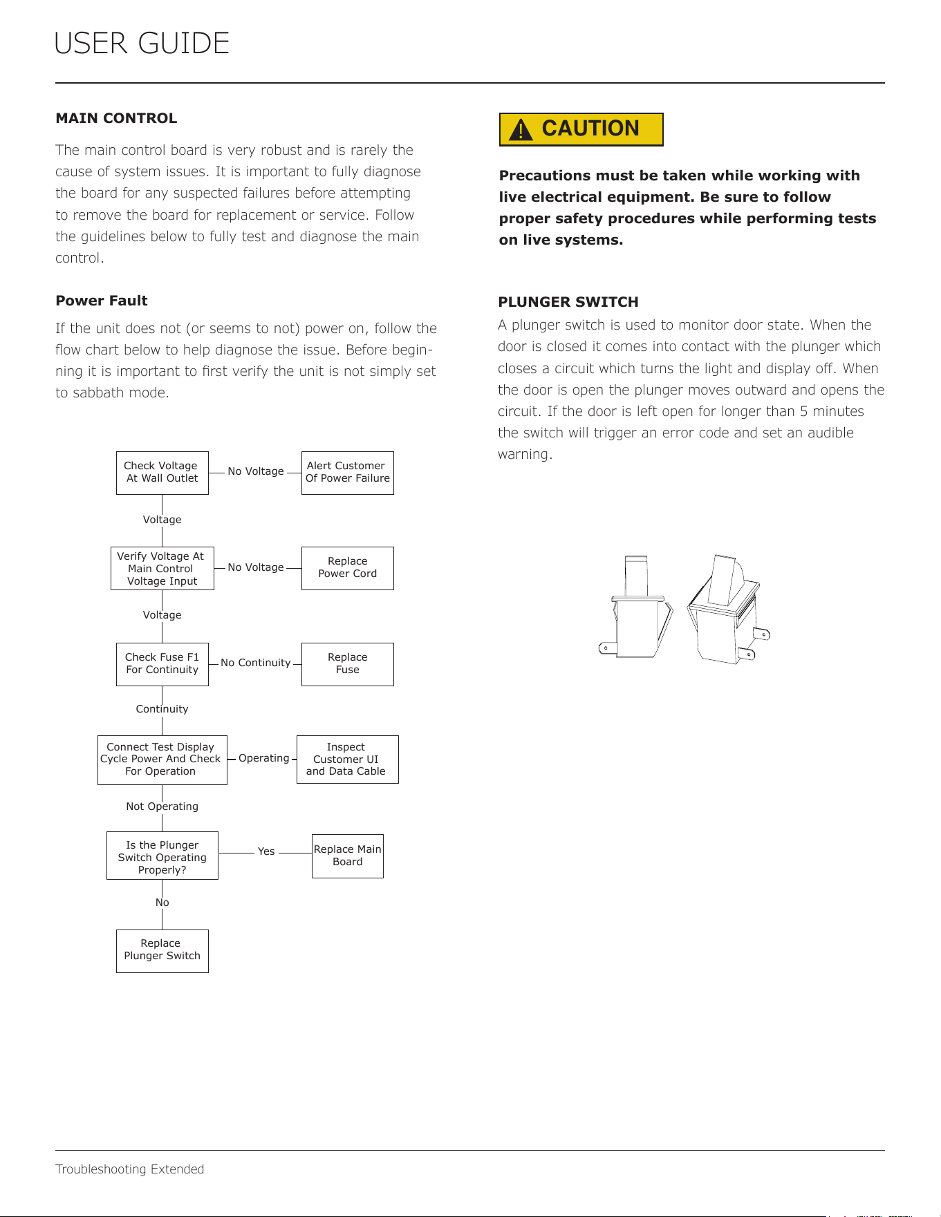
MAIN CONTROL
The main control board is very robust and is rarely the
cause of system issues. It is important to fully diagnose
the board for any suspected failures before attempting
to remove the board for replacement or service. Follow
the guidelines below to fully test and diagnose the main
control.
Power Fault
If the unit does not (or seems to not) power on, follow the
ow chart below to help diagnose the issue. Before begin-
ning it is important to rst verify the unit is not simply set
to sabbath mode.
Check Voltage
At Wall Outlet
Verify Voltage At
Main Control
Voltage Input
Check Fuse F1
For Continuity
Replace
Plunger Switch
Replace Main
Board
Replace
Fuse
Replace
Power Cord
Alert Customer
Of Power Failure
Is the Plunger
Switch Operating
Properly?
Inspect
Customer UI
and Data Cable
Connect Test Display
Cycle Power And Check
For Operation
No Voltage
No Voltage
Voltage
Continuity
Operating
Not Operating
No Continuity
No
Yes
Voltage
CAUTION
!
Precautions must be taken while working with
live electrical equipment. Be sure to follow
proper safety procedures while performing tests
on live systems.
PLUNGER SWITCH
A plunger switch is used to monitor door state. When the
door is closed it comes into contact with the plunger which
closes a circuit which turns the light and display o. When
the door is open the plunger moves outward and opens the
circuit. If the door is left open for longer than 5 minutes
the switch will trigger an error code and set an audible
warning.
39
USER GUIDE
Thermistor
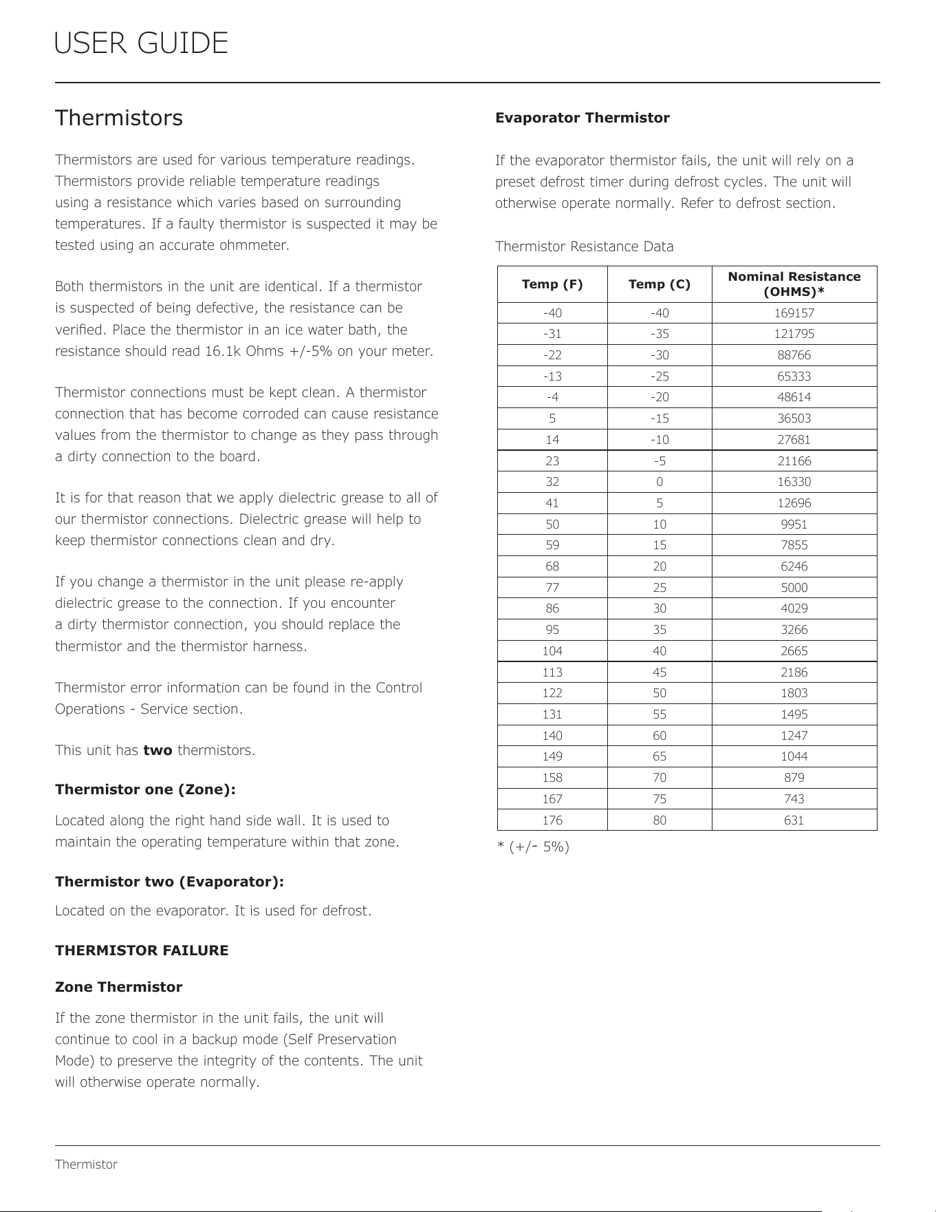
Evaporator Thermistor
If the evaporator thermistor fails, the unit will rely on a
preset defrost timer during defrost cycles. The unit will
otherwise operate normally. Refer to defrost section.
Thermistor Resistance Data
Thermistors
Thermistors are used for various temperature readings.
Thermistors provide reliable temperature readings
using a resistance which varies based on surrounding
temperatures. If a faulty thermistor is suspected it may be
tested using an accurate ohmmeter.
Both thermistors in the unit are identical. If a thermistor
is suspected of being defective, the resistance can be
veried. Place the thermistor in an ice water bath, the
resistance should read 16.1k Ohms +/-5% on your meter.
Thermistor connections must be kept clean. A thermistor
connection that has become corroded can cause resistance
values from the thermistor to change as they pass through
a dirty connection to the board.
It is for that reason that we apply dielectric grease to all of
our thermistor connections. Dielectric grease will help to
keep thermistor connections clean and dry.
If you change a thermistor in the unit please re-apply
dielectric grease to the connection. If you encounter
a dirty thermistor connection, you should replace the
thermistor and the thermistor harness.
Thermistor error information can be found in the Control
Operations - Service section.
This unit has two thermistors.
Thermistor one (Zone):
Located along the right hand side wall. It is used to
maintain the operating temperature within that zone.
Thermistor two (Evaporator):
Located on the evaporator. It is used for defrost.
THERMISTOR FAILURE
Zone Thermistor
If the zone thermistor in the unit fails, the unit will
continue to cool in a backup mode (Self Preservation
Mode) to preserve the integrity of the contents. The unit
will otherwise operate normally.
USER GUIDE
u-line.com
Thermistor
Thermistors are used for various temperature readings.
Thermistors provide reliable temperature readings using a
resistance which varies based on surrounding temperatures.
If a faulty thermistor is suspected, it may be tested using
an accurate ohmmeter.
Thermistor connections must be kept clean. A thermistor
connection that has become corroded can cause resistance
values from the thermistor to change as they pass through
a dirty connection to the board.
It is for that reason that we apply dielectric grease to all of
our thermistor connections. Dielectric grease will help to
keep thermistor connections clean and dry.
If you change a thermistor in the unit, please re-apply
dielectric grease to the connection. If you encounter a dirty
thermistor connection, you should replace the thermistor
and the thermistor harness.
This unit has one thermistor located along the right hand
sidewall of the ice bin. It is used to maintain the ice level in
the bin.
Thermistor Resistance Data
* (+/
- 5%)
Thermistor
Temp (F) Temp (C)
Nominal Resistance
(OHMS)*
-40 -40 169157
-31 -35 121795
-22 -30 88766
-13 -25 65333
-4 -20 48614
5 -15 36503
14 -10 27681
23 -5
21166
32 0 16330
41 5 12696
50 10 9951
59 15 7855
68 20 6246
77 25 5000
86 30 4029
95 35 3266
104 40 2665
113 45 2186
122 50 1803
131 55 1495
140 60 1247
149 65 1044
158 70 879
167 75 743
176 80 631
40
USER GUIDE
Defrost
Defrost
This unit defrosts, by default, every 12 hours of compressor runtime for 45 minutes. If you have veried that
the unit does not have an ambient air leak, refer to the Control Operation - Service section and adjust unit to
defrost every 9 hours for 60 minutes. Also, adjust the #2 thermistor to -4 instead of 0.
41
ENSURING YOUR WARRANTY STAYS VALID
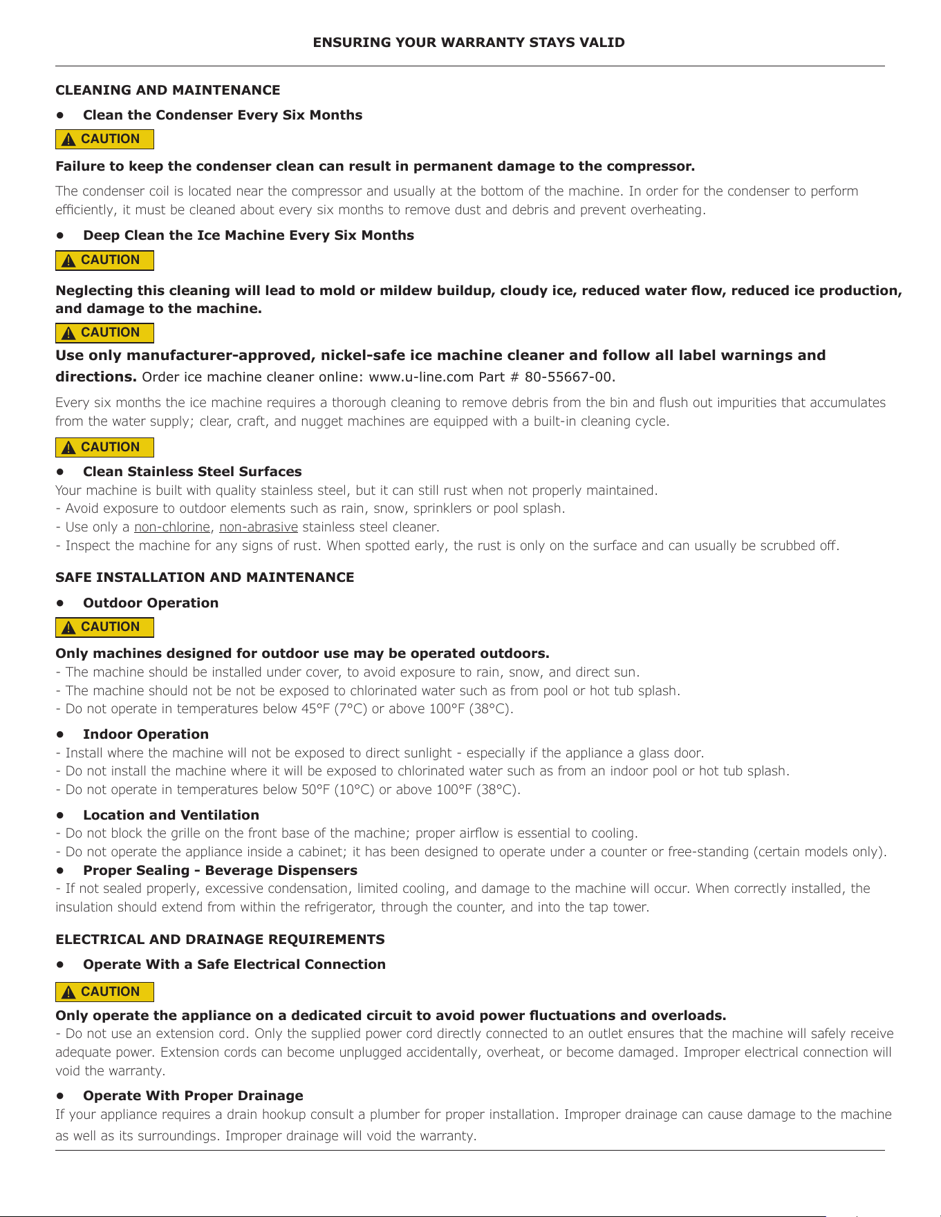
CLEANING AND MAINTENANCE
• Clean the Condenser Every Six Months
Failure to keep the condenser clean can result in permanent damage to the compressor.
The condenser coil is located near the compressor and usually at the bottom of the machine. In order for the condenser to perform
eciently, it must be cleaned about every six months to remove dust and debris and prevent overheating.
• Deep Clean the Ice Machine Every Six Months
Neglecting this cleaning will lead to mold or mildew buildup, cloudy ice, reduced water ow, reduced ice production,
and damage to the machine.
Use only manufacturer-approved, nickel-safe ice machine cleaner and follow all label warnings and
directions. Order ice machine cleaner online: www.u-line.com Part # 80-55667-00.
Every six months the ice machine requires a thorough cleaning to remove debris from the bin and ush out impurities that accumulates
from the water supply; clear, craft, and nugget machines are equipped with a built-in cleaning cycle.
• Clean Stainless Steel Surfaces
Your machine is built with quality stainless steel, but it can still rust when not properly maintained.
- Avoid exposure to outdoor elements such as rain, snow, sprinklers or pool splash.
- Use only a non-chlorine, non-abrasive stainless steel cleaner.
- Inspect the machine for any signs of rust. When spotted early, the rust is only on the surface and can usually be scrubbed o.
SAFE INSTALLATION AND MAINTENANCE
• Outdoor Operation
Only machines designed for outdoor use may be operated outdoors.
- The machine should be installed under cover, to avoid exposure to rain, snow, and direct sun.
- The machine should not be not be exposed to chlorinated water such as from pool or hot tub splash.
- Do not operate in temperatures below 45°F (7°C) or above 100°F (38°C).
• Indoor Operation
- Install where the machine will not be exposed to direct sunlight - especially if the appliance a glass door.
- Do not install the machine where it will be exposed to chlorinated water such as from an indoor pool or hot tub splash.
- Do not operate in temperatures below 50°F (10°C) or above 100°F (38°C).
• Location and Ventilation
- Do not block the grille on the front base of the machine; proper airow is essential to cooling.
- Do not operate the appliance inside a cabinet; it has been designed to operate under a counter or free-standing (certain models only).
• Proper Sealing - Beverage Dispensers
- If not sealed properly, excessive condensation, limited cooling, and damage to the machine will occur. When correctly installed, the
insulation should extend from within the refrigerator, through the counter, and into the tap tower.
ELECTRICAL AND DRAINAGE REQUIREMENTS
• Operate With a Safe Electrical Connection
Only operate the appliance on a dedicated circuit to avoid power uctuations and overloads.
- Do not use an extension cord. Only the supplied power cord directly connected to an outlet ensures that the machine will safely receive
adequate power. Extension cords can become unplugged accidentally, overheat, or become damaged. Improper electrical connection will
void the warranty.
• Operate With Proper Drainage
If your appliance requires a drain hookup consult a plumber for proper installation. Improper drainage can cause damage to the machine
as well as its surroundings. Improper drainage will void the warranty.
CAUTION
!
CAUTION
!
CAUTION
!
CAUTION
!
CAUTION
!
CAUTION
!
42
Middleby Refrigeration | 1260 E. Van Deinse, Greenville, MI 48838
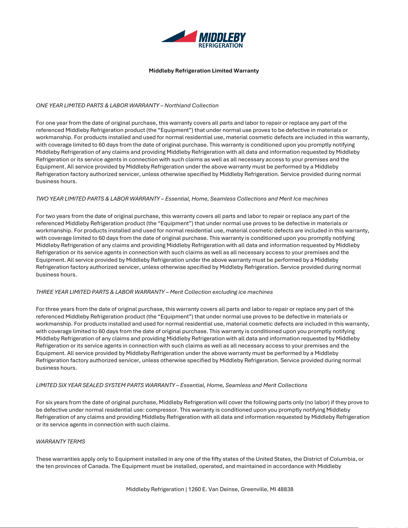
Middleby Refrigeration Limited Warranty
ONE YEAR LIMITED PARTS & LABOR WARRANTY – Northland Collection
For one year from the date of original purchase, this warranty covers all parts and labor to repair or replace any part of the
referenced Middleby Refrigeration product (the “Equipment”) that under normal use proves to be defective in materials or
workmanship. For products installed and used for normal residential use, material cosmetic defects are included in this warranty,
with coverage limited to 60 days from the date of original purchase. This warranty is conditioned upon you promptly notifying
Middleby Refrigeration of any claims and providing Middleby Refrigeration with all data and information requested by Middleby
Refrigeration or its service agents in connection with such claims as well as all necessary access to your premises and the
Equipment. All service provided by Middleby Refrigeration under the above warranty must be performed by a Middleby
Refrigeration factory authorized servicer, unless otherwise specified by Middleby Refrigeration. Service provided during normal
business hours.
TWO YEAR LIMITED PARTS & LABOR WARRANTY – Essential, Home, Seamless Collections and Merit Ice machines
For two years from the date of original purchase, this warranty covers all parts and labor to repair or replace any part of the
referenced Middleby Refrigeration product (the “Equipment”) that under normal use proves to be defective in materials or
workmanship. For products installed and used for normal residential use, material cosmetic defects are included in this warranty,
with coverage limited to 60 days from the date of original purchase. This warranty is conditioned upon you promptly notifying
Middleby Refrigeration of any claims and providing Middleby Refrigeration with all data and information requested by Middleby
Refrigeration or its service agents in connection with such claims as well as all necessary access to your premises and the
Equipment. All service provided by Middleby Refrigeration under the above warranty must be performed by a Middleby
Refrigeration factory authorized servicer, unless otherwise specified by Middleby Refrigeration. Service provided during normal
business hours.
THREE YEAR LIMITED PARTS & LABOR WARRANTY – Merit Collection excluding ice machines
For three years from the date of original purchase, this warranty covers all parts and labor to repair or replace any part of the
referenced Middleby Refrigeration product (the “Equipment”) that under normal use proves to be defective in materials or
workmanship. For products installed and used for normal residential use, material cosmetic defects are included in this warranty,
with coverage limited to 60 days from the date of original purchase. This warranty is conditioned upon you promptly notifying
Middleby Refrigeration of any claims and providing Middleby Refrigeration with all data and information requested by Middleby
Refrigeration or its service agents in connection with such claims as well as all necessary access to your premises and the
Equipment. All service provided by Middleby Refrigeration under the above warranty must be performed by a Middleby
Refrigeration factory authorized servicer, unless otherwise specified by Middleby Refrigeration. Service provided during normal
business hours.
LIMITED SIX YEAR SEALED SYSTEM PARTS WARRANTY – Essential, Home, Seamless and Merit Collections
For six years from the date of original purchase, Middleby Refrigeration will cover the following parts only (no labor) if they prove to
be defective under normal residential use: compressor. This warranty is conditioned upon you promptly notifying Middleby
Refrigeration of any claims and providing Middleby Refrigeration with all data and information requested by Middleby Refrigeration
or its service agents in connection with such claims.
WARRANTY TERMS
These warranties apply only to Equipment installed in any one of the fifty states of the United States, the District of Columbia, or
the ten provinces of Canada. The Equipment must be installed, operated, and maintained in accordance with Middleby
43
Middleby Refrigeration | 1260 E. Van Deinse, Greenville, MI 48838
Refrigeration Brand User Guides, copies of which were provided to you with the Equipment or otherwise will be furnished to you
upon request. Further, this warranty applies only to Equipment shipped from the Middleby Refrigeration facility after July 1, 2025,
and purchased from an authorized dealer.
Except as provided in the Limited Warranty above, the Equipment is provided “as-is”. Middleby Refrigeration claims all other
warranties, express, statutory or implied, including without limitation, the implied warranties of title, non-infringement,
merchantability and fitness for a particular purpose. Middleby Refrigeration does not warrant that the Equipment will meet your
specifications or needs. You acknowledge that you are solely responsible for the selection of the Equipment and determining the
suitability of the Equipment for your needs.
Any warranty that may be implied in connection with your purchase or use of the product, including any warranty of
merchantability or any warranty that fits for a particular purpose is limited to the duration of these warranties. Some states do not
allow limitations on how long an implied warranty lasts, so the above limitations may not apply to you.
The warranties only apply to the original purchaser and are non-transferable.
The warranties apply to units operated outside only if designed for outdoor use by model and serial number.
Replacement water filters, light bulbs, and other consumable parts are not covered by these warranties.
The start of Middleby Refrigeration’s obligation is limited to four years after the shipment date from Middleby Refrigeration.
In-home instruction on how to use your product is not covered by these warranties.
Food, beverage, and medicine loss are not covered by these warranties.
If the Equipment is located in an area where Middleby Refrigeration factory authorized service is not available, you may be
responsible for a trip charge or you may be required to bring the Equipment to a Middleby Refrigeration factory authorized
service location at your own cost and expense.
Units purchased after use as floor displays, and/or certified reconditioned units, are covered by the limited one-year warranty
only and no coverage is provided for cosmetic defects.
Signal issues related to Wi-Fi connectivity are not covered by these warranties.
Equipment that is not installed, operated and maintained in accordance with Middleby Refrigeration’s Use and Care Manual
or other written materials provided to you by Middleby Refrigeration or available for the Equipment (as may be updated by
Middleby Refrigeration from time to time, the “Manual”), a copy of which is provided to you with the Equipment or otherwise
will be furnished to you upon request, is excluded from this warranty. This warranty does not apply to damage or failure which
results, in Middleby Refrigeration’s or its service agent’s sole opinion, from failure to provide a suitable installation and
operating environment (including power and HVAC if applicable) and facilities as prescribed by the Manual, misuse, abuse,
accident or improper use, neglect, power failure or power surges (over or under voltage), or to damage or failure from flood,
fire, lightning or other natural or man-made disasters, or other Acts of God, or to Equipment that has missing or altered serial
numbers.
Modifications and Repair: Equipment that has been modified or altered by persons other than Middleby Refrigeration’s or its
service agents, or Equipment that has had non-approved devices or connection items attached thereto, is excluded from
coverage under this warranty. Repair of the Equipment by anyone other than Middleby Refrigeration’s or its authorized service
agents will void all warranties on the Equipment.
44
Middleby Refrigeration | 1260 E. Van Deinse, Greenville, MI 48838
Accessories: Accessories and parts (collectively “Accessories”) that are consumed in the normal course of Equipment
operation or maintenance are excluded from this warranty. Failure of or damage to Equipment or components from the use of
non-approved cleaning chemicals, devices or processes is also excluded from this warranty.
Warranty Service, Exclusive Remedy
Middleby Refrigeration will be solely responsible for determining whether or not the Equipment or any component thereof is
defective. Defective components covered by this warranty will be repaired or replaced at Middleby Refrigeration’s option
without charge to you and such repaired or replacement components will be covered by this warranty for the balance of the
Warranty Period. Parts used in the repair of defective components and replacement components may be new, recovered or
rebuilt. At its sole option, Middleby Refrigeration may decide to replace defective Equipment covered by this warranty with
new, recovered or rebuilt Equipment of equal or greater capability, and such Equipment will be covered by this Limited
Warranty for the balance of the Warranty Period. Defective Equipment and components will become the property of Middleby
Refrigeration. This paragraph states Middleby Refrigeration’s sole and exclusive obligation and liability and your sole and
exclusive remedy under this warranty. Middleby Refrigeration shall not be responsible for a failure to provide warranty
services due to causes beyond Middleby Refrigeration’s or its service agents’ control.
Warranty Claims
Claims under this warranty must be reported to Middleby Refrigeration under such reporting service as Middleby Refrigeration
may designate. Upon receipt of the claim and related information and preliminary verification that the claim is valid, Middleby
Refrigeration will promptly notify an authorized service agent to contact you and arrange for an on-site repair visit during the
service agent’s normal working hours. Any costs incurred by Middleby Refrigeration or its service agent associated with a
service agent being refused or unable to gain access to the Equipment on your premises, or a claim not covered by this
warranty, will be charged to you.
Disclaimer of Damages
Middleby Refrigeration disclaims all incidental, special and consequential damages, including but not limited to loss of use,
lost revenue or profits, or substitute use, suffered by you or any third party, whether arising in contract, tort (including
negligence), or otherwise, resulting from any breach by Middleby Refrigeration or its service agents of this warranty, or
resulting from the manufacture, use, or defects, of or in the Equipment, even if Middleby Refrigeration was apprised of the
possibility of such damages.
Customer Indemnity
You agree to indemnify, defend and hold Middleby Refrigeration harmless from all third-party claims, demands, judgments,
fees and costs directly or indirectly arising out of or related to your use of the Equipment. You further agree to indemnify and
hold Middleby Refrigeration harmless from any incidental, consequential or special damage suffered by you, including lost
revenue or profits, loss of use, or substitute use, during periods of Equipment failure or loss of use.
Governing Law, Entire Warranty
This warranty shall be governed and construed in accordance with the laws of the State of Michigan, USA (except with respect
to its provisions regarding conflicts of laws). The warranty described herein is the complete and only warranty for Equipment
and supersedes all prior oral or written agreements and understandings that may have existed between us relating to
Equipment warranties. The terms of this warranty may not be altered, amended or modified except by a signed writing from
Middleby Refrigeration. Any purported alteration, amendment or modification by a service agent or anyone else will not be
enforceable against Middleby Refrigeration.
45
Middleby Refrigeration | 1260 E. Van Deinse, Greenville, MI 48838
Charges for Non-Warranty Service or Rejection of Service Visit
In the event that repairs, replacement or service are provided by Middleby Refrigeration’s service agents for work not covered
by this limited warranty, customers agree to pay the service agent directly according to the service agent’s normal scale of
charges. In the event Middleby Refrigeration is invoiced by the service agent for services not covered under this extended
warranty, Middleby Refrigeration will invoice customer, and customer will pay such invoice based on terms of net 10 days.
Customer also agrees to pay any cost incurred by Middleby Refrigeration or its service agent associated with a service agent
responding to a call for service but then being refused or unable to gain access to the Equipment on Customer’s premises.
Failure to submit payment may, at Middleby Refrigeration’s discretion, result in Middleby Refrigeration voiding the balance of
the warranty. In no event will Middleby Refrigeration authorize a customer with an outstanding Non-Warranty invoice.
For parts and service assistance, or to find factory authorized service near you, contact Middleby Refrigeration at
616.754.5601.
46
