
SDH 6025WH
EN
SMART MOBILE DEHUMIDIFIER
60L WI-FI
Translation of the original manual
SDH 6025WH
A
1
2
3
4
5
6
7
8
9
12
10
11
B
1 2 3 4 5 6 7
8 9 10
11 12 13
C
D
E
F

- 1 -
07/2025
2025, .
EN
Smart Mobile Dehumidifier 60l Wi-Fi
User Manual
IMPORTANT SAFETY INSTRUCTIONS
READ CAREFULLY AND STORE FOR FUTURE USE.
• This appliance may be only used by children aged
8years and older and by persons with physical, sensory
or mental impairments or lack of experience and
knowledge, if they are supervised or have been instructed
on the safe use of the appliance and understand the
potential hazards.
• Cleaning and maintenance must not be performed by
unsupervised children. Children must not play with the
appliance.
• If the power cord is damaged, it must be replaced by an
authorised service centre or by another similarly qualified
person, this will prevent the creation of adangerous
situation. It is forbidden to use the appliance if it has
adamaged power cord.
• The appliance must be installed in accordance with
national installation codes.
• The appliance must be stored in amanner that prevents its
mechanical damage.
• The appliance must be stored in awell ventilated location,
where the dimensions of the room must correspond to the
dimensions specified for its operation.
• The appliance must be stored in aroom where an
open flame is not continuously in use (e.g. running gas
- 2 -
07/2025
2025, .
appliance) or where there are sources of ignition (e.g.
running electrical heating element).
. . . . . . . . . . . . . . . . . . . . . . . . . . . . . . . . . . . . . . . . . . . . . . . . . . . . . . . . . . . . . . . . . . . . . . . . . . . . . . . . . . . . . . . . . . . . . . . . . . . . . . . . . . . . . . . . . . . . . . . . . . . . . . . . . . . . . . . . . . . .
• Before connecting the appliance to apower socket, check that the rated voltage on its rating label matches the electrical voltage in the power socket.
• Connect the appliance only to aproperly earthed socket.
• The power socket must be freely accessible so that it is possible to quickly disconnect the power cord from the power source if necessary.
• The appliance is designed for use in household, offices and similar types of areas. Do not use it in rooms where it could be exposed to dripping or
spraying water, where it could be exposed to direct sunlight, in areas where chemical or explosive substances are stored, in industrial surroundings
or outdoors. Do not use it in the vicinity of abath, shower, swimming pool, etc.
• Keep the appliance away from open flames or heat sources.
• Do not place the appliance on unstable surfaces such as carpets with very long and thick fibres.
• The appliance may only be used on adry, stable, smooth and horizontal surface.
• The appliance is equipped with travel wheels so pay extra attention when handling it so that it does not fall down stairs or travel down from sloped
areas. If necessary secure the wheels using the stoppers.
• Only use original parts to assemble the appliance. Before starting to assemble the appliance, make sure that it is turned off and disconnected from the
power socket.
• Prior to connecting the appliance to apower socket, make sure that the appliance is correctly assembled according to the instructions in this user'smanual.
• Do not touch the appliance with wet or damp hands. This applies especially when it is connected to apower socket.
• Do not submerge the appliance in water or in any other liquid.
• Do not cover or insert anything into the air inlet or air outlet openings. This could damage the appliance.
• During operation, there must be sufficient space for air circulation with at least 30 cm of free space on all sides.
• Do not expose yourself to acold air current for along time. This could have anegative effect on your health.
• To turn the appliance on or off, always use the appropriate buttons on the control panel. Do not turn off the appliance by disconnecting the power
cord from the power socket.
• Always turn off the appliance and disconnect it from the power socket when leaving it without supervision, when not using it and before moving,
disassembling or cleaning it.
• Do not attempt to remove the outer case of the appliance.
• Unplug the appliance from the power socket by pulling the plug, not the power cord. Otherwise, damage to the power cord or the socket could occur.
• Do not use the appliance if damaged in any way, or with adamaged mains cable or plug.
• Store the appliance in avertical position. It may only be transported in the vertical position. If you have already used the appliance, check that all the
condensate has been drained. After transporting it, wait at least 1 hour before using the appliance.
• Do not use the appliance if it is not working correctly, if it has been damaged or has been submerged in water. To avoid ahazardous situation arising,
do not repair the device yourself or modify it in any way. All repairs should be carried out by an authorised service centre. Tampering with the
appliance may result in the loss of your legal rights regarding faulty performance or warranty for quality.
• This appliance is intended for use by experts or trained personnel in stores, light industry and in agriculture, or for commercial use by ordinary people.
. . . . . . . . . . . . . . . . . . . . . . . . . . . . . . . . . . . . . . . . . . . . . . . . . . . . . . . . . . . . . . . . . . . . . . . . . . . . . . . . . . . . . . . . . . . . . . . . . . . . . . . . . . . . . . . . . . . . . . . . . . . . . . . . . . . . . . . . . . . .
Read this user'smanual carefully prior to installing
or operating your new appliance. Make sure to keep
it for future reference.
Read the technical documentation.
Read the user'smanual.
Fire hazard
The appliance contains aflammable refrigerant. It is
necessary to adhere to safety instructions.
. . . . . . . . . . . . . . . . . . . . . . . . . . . . . . . . . . . . . . . . . . . . . . . . . . . . . . . . . . . . . . . . . . . . . . . . . . . . . . . . . . . . . . . . . . . . . . . . . . . . . . . . . . . . . . . . . . . . . . . . . . . . . . . . . . . . . . . . . . . .

- 3 -
07/2025
2025, .
SERVICE MANUAL
• The service manual is intended only for aqualified person who is authorized to handleflammable refrigerants.
1.1 Checking the area
Before starting work on asystem containing flammable refrigerants, safety checks are necessary to ensure that the risk of ignition is minimized.
Whenrepairing the cooling system, the following precautions must be taken before carrying out work on it.
1.2 Working procedure
The work must be carried out in acontrolled manner so as to minimize the risk of flammable gases or vapours being present when the work is carried
out.
1.3 Overall working space
All maintenance personnel andother on-site workers must be instructed about thenature ofthe work being done. Work in confined spaces must be
avoided. The area around the workplace must be divided into sections. It must be ensured that the conditions inside the space are safe by carrying out
acheck of flammable materials.
1.4 Checking the presence of refrigerant
The space must be inspected by an appropriate refrigerant detector before andduring operation to ensure technicians are aware ofpotentially
flammable atmospheres. It must be ensured that the leakage detection equipment used is suitable for use on flammable refrigerants, i.e. non-sparking,
adequately sealed or intrinsically safe.
1.5 Presence of fire extinguisher
If any hot work is to be carried out on the refrigeration equipment or associated parts, suitable fire extinguishing equipment must be at hand. The fire
extinguisher must be powder or CO
2
in the vicinity of the filling area.
1.6 No ignition sources
No person carrying out work on arefrigeration system involving the stripping of any pipework containing or having contained flammable refrigerant
shall use any sources of ignition in such away as to result in arisk of fire or explosion. All possible ignition sources, including cigarette smoking, should
be kept sufficiently away from the installation, repair, removal anddisposal sites during which the flammable refrigerant may eventually be discharged
into the surrounding area. Before work is carried out, the area around the equipment must be inspected to ensure that there are no burning or ignition
hazards. “No smoking” signs must be displayed.
1.7 Ventilated Space
It must be ensured that the space is open or adequately ventilated before the system is disrupted or hot work is carried out. The ventilation intensity
must last for the duration of the work. Ventilation should safely disperse any discharged refrigerant andpreferentially take it out into the atmosphere.
1.8 Checks of refrigerating equipment
Where electrical components are changed, the components shall be suitable for this purpose andcomply with the correct specification. Always
follow the manufacturer'sinstructions for maintenance andservice. If doubts arise, the technical department of the manufacturer must be consulted
forassistance.
Forinstallations containing flammable refrigerants, the following checks must be carried out:
• the size of the refill is consistent with the size of the room in which the refrigerant-containing parts are installed;
• ventilation units andoutlets work at full capacity andare not clogged;
• if an indirect refrigerant circuit is used, the second circuit must be checked for the presence of refrigerant;
• the marking of the device must always be visible andlegible; markings andmarks that are not legible must be repaired;
• cooling pipes or components are installed inplaces where they are unlikely to be exposed to any substances that may corrode the components
containing the refrigerant, unless these components are constructed ofmaterials that are internally resistant to corrosion or are suitably protected
against corrosion.
1.9 Electrical Instrument Inspection
Repairs andmaintenance of electrical components must include safety checks andinspection of components.
If afault occurs that could compromise safety, then no electrical power must be connected to the circuit until the fault is satisfactorily resolved.
If the malfunction cannot be corrected immediately but work must be continued, an appropriate temporary solution must be used. This must be
communicated to the owner of the device so that all parties are aware ofit.
Initial security checks must ensure:
• that the capacitors are discharged: this must be done in asafe manner to avoid the possibility of sparks;
• that no electrical components andlines are exposed during filling, refreshing andcleaning of the system;
• that the grounding is not broken.
2. Servicing of sealed components
During repairs of sealed components, all electrical power must be disconnected from the equipment being worked on before the sealed lids are
removed, etc. If it is absolutely necessary to have electrical power at the equipment during service, then apermanently operating leak detection device
must be placed at the most critical point to warn of apotentially hazardous situation.
Particular care must be taken to ensure that work on electrical components has not altered the enclosure to such an extent as to affect the level of
protection. This must include damage to cables, excessive number of connections andterminals not made according to the original specification,
damage to seals, improper implementation of seals, etc.
It must be ensured that the appliance is mounted securely.
It must be ensured that the gaskets or sealing materials are not deteriorated so that they no longer serve the purpose of preventing the ingress of
flammable environments. Replacement parts must be inaccordance with the manufacturer'sspecifications.
Note:
The use of asilicone seal may inhibit the effectiveness of some types of leak detection devices. Internally safe components do not need
to be disconnected before they can be worked on.

- 4 -
07/2025
2025, .
3. Service of intrinsically safe components
No permanent inductive or capacitive load shall be applied to the circuit without ensuring that the permissible voltage andcurrent permitted for the
equipment in use are not exceeded.
Internally safe components are the only types that can be worked on in aflammable environment, evenif they are alive. The test apparatus must be
correctly dimensioned.
Parts are replaced only by parts specified by the manufacturer. Other parts may result in ignition of the refrigerant during leakage into the environment.
4. Cabling
It shall be checked that the wiring is not exposed to wear, corrosion, excessive pressure, vibration, sharp edges or any other adverse effects of the
environment. The check must also take intoaccount the effects of ageing or permanent vibrations from sources such as compressors or fans.
5. Use of flammable coolant
Under no circumstances should potential sources of ignition be used to search for or detect refrigerant leaks.
The halogen burner (or any other detector using an open flame) shall not be used.
6. Leak detection methods
The following leak detection methods are considered acceptable for systems containing flammable refrigerants.
Electronic leak detectors must be used to detect flammable refrigerants, but their sensitivity may not be adequate or may require recalibration. (The
detection device must be calibrated in arefrigerant-free compartment.) It must be ensured that the detector acquires apotential source of ignition
andthat it is suitable for the refrigerant used. The leak detection device must be set to apercentage of refrigerant LFL andmust be calibrated to the
refrigerant used and the appropriate percentage of gas confirmed (maximum 25%).
Leak detection fluids are suitable for use withmost refrigerants, but the use of chlorine-containing detergents must be excluded as chlorine may react
with the refrigerant andcorrode copper piping.
If leakage is suspected, all open fires must be removed/extinguished.
If arefrigerant leakage is found, which requires brazing, all refrigerant must be removed from the system or separated (by closing the valves) in the part
of the system away from the leakage. The system must then be purified with oxygen-free nitrogen (OFN), both before and after the brazing process.
7. Removal anddraining
Conventional procedures must be used when the cooling circuit is disrupted for repairs – or for any other reason. However, it is important to stick to the
best method because of the flammability. The following procedure must be followed:
• remove refrigerant;
• clean the circuit with inert gas;
• drain;
• clean again with inert gas;
• open the circuit by cutting or brazing.
The circuit filling must be removed to the correct sampling cylinders. The system must be “flooded” with OFN (oxygen-free nitrogen) to make the unit
safe. The procedure may need to be repeated several times. Compressed air or oxygen must not be used for this task.
Flooding can be achieved by disrupting the vacuum in the system with using OFN andcontinuing filling until the operating pressure is reached, then
venting into the air andfinally reducing to avacuum. This process must be repeated as long as the refrigerant is in thesystem. When the last refill of
OFN is used, the system must be vented to atmospheric pressure to allow the work to be carried out. This operation is absolutely necessary if brazing is
to be carried out on the pipeline.
It must be ensured that the outlets for the pump are not close to any source of ignition andthat ventilation is provided.
8. Filling procedure
In addition to conventional filling procedures, the following requirements must be observed.
• It must be ensured that there is no contamination by various refrigerants when using the filling device. Hoses or pipes must be as short as possible to
minimize the amount of refrigerant contained inthem.
• The cylinders must be held vertically.
• Ensure that the cooling system is earthed before filling the system with refrigerant.
• When filling is complete, the system must be labelled (if it is not already).
• Extreme care must be taken not to overfill the cooling system.
Before refilling the system, it must be pressure tested with OFN. The system must be tested forleakage after filling but before commissioning.
Averification test must be carried out before leaving the assembly site.
9. Decommissioning
Before performing this procedure, it is essential that the technician is fully acquainted with the equipment andall its details. Good practice is
recommended to remove all refrigerant safely. Oil andrefrigerant samples must be taken if analysis is required before the regenerated refrigerant can be
reused. It is essential that electricity is available before starting this activity.
a) Familiarization with the equipment andits operation.
b) Electrical disconnection of the system.
c) Before starting the procedure, ensure that:
– amechanical device for handling the refrigerant cylinders was available, if required;
– all personal protective equipment was available and used correctly;
– the decommissioning procedure was constantly supervised by acompetent person;
– the sampling device andthe cylinders comply with the relevant standards.
d) Drain the cooling system if possible.
e) If it is not possible to achieve avacuum, acollection pipe is made so that the refrigerant can be taken from thedifferent parts of the system.
f) Ensure that the cylinder is placed on the scales before the sampling takes place.
g) The sampling device is switched on and the work is carried out according to the manufacturer'sinstructions.
h) The cylinders will not overfill. (No more than 80% of the liquid content of the cartridge.)
i) The maximum working pressure of the cylinder shall not be exceeded, even temporarily.
j) When the cylinders are properly filled and the procedure is completed, ensure that the cylinders andequipment are immediately removed from the
installation site andall isolation valves on the equipment are closed.
k) The removed refrigerant must not be filled into another refrigeration system until it has been cleaned andinspected.
- 5 -
07/2025
2025, .
10. Label precautions
• The device must be provided with alabel stating that it has been decommissioned andis free of refrigerant. The label must be dated andsigned.
Ensure that the equipment bears labels indicating that the equipment contains aflammable refrigerant.
11. Removing
• When the refrigerant is removed from the system, either for service or for decommissioning, good practice is recommended that all refrigerants are
removed safely.
• When transferring the refrigerant to the cylinders, it must be ensured that only appropriate cylinders are used to remove the refrigerant.
• It must be ensured that the correct number of cylinders is available to accommodate the total system load. All cylinders to be used must be
designed for the refrigerant to be removed andmarked with alabel for this refrigerant (i.e. special cylinders for refrigerant removal). The cylinders
must be complete withsafety valve andassociated shut-off valves ingood operating condition. Empty sampling cylinders are drained and cooled
down if possible prior to collection.
• Sampling devices must be ingood working order with aset of instructions related to the devices that are at hand andmust be suitable for
removing flammable refrigerants. In addition, aset of calibrated scales ingood operating condition must be available. The hose must be complete
withdetachable couplings without leakage andingood condition. Before using the sampling device, it shall be checked that it is insatisfactory
operating condition, has been properly maintained andthat all associated electrical components are sealed to prevent ignition in the event of
refrigerant discharge. If inany doubt, the manufacturer shall be consulted.
• The collected refrigerant must be returned to the refrigerant supplier in the correct collection cylinder andwith the appropriate agreed waste transfer
letter. Refrigerants are not mixed in the sampling units, andespecially not in the cylinders.
• If compressors or compressor oils are to be removed, ensure that they have been drained to an acceptable level to ensure that no flammable
refrigerant remains in thelubricant. The draining procedure must be carried out before the compressor is returned to the supplier. Only electric
heating of the compressor body must be used to speed up this process. When oil is drained from the system, it must be safely removed.
. . . . . . . . . . . . . . . . . . . . . . . . . . . . . . . . . . . . . . . . . . . . . . . . . . . . . . . . . . . . . . . . . . . . . . . . . . . . . . . . . . . . . . . . . . . . . . . . . . . . . . . . . . . . . . . . . . . . . . . . . . . . . . . . . . . . . . . . . . . .
SPECIFIC INFORMATION FOR APPLIANCES USING REFRIGERANT GAS R290
• Carefully study all the warnings.
• For defrosting and cleaning, do not use any other tools than those recommended by the manufacturer.
• The appliance must be stored in aroom where there are no sources of ignition (e.g. open flame, gas appliance in operation, electrical heating
equipment in operation) in continuous operation.
• Do not puncture or burn the cooling circuit.
• It is necessary to take into consideration that refrigerants may be odourless.
• The appliance must be installed, operated and stored in aroom with afloor area greater than 3 m
2
.
• This appliance contains 150 g of the R290 refrigerant gas.
• R290 is arefrigerant gas that meets European environmental protection directives. Do not drill into or damage any part of the cooling circuit.
• Sufficient ventilation must be provided in the room where this appliance is installed operated or stored. Otherwise, there is arisk of an explosion or
fire in the event that leaked refrigerant ignites, e.g. when agas cooker is turned on, etc.
• The appliance must be stored in such amanner that its mechanical damage is prevented.
• Persons working with or repairing cooling circuits must have appropriate authorisation issued by an authorised institution that certifies this
person'scompetence to work with refrigerants in accordance with the specific assessment of the association for this sector.
• Maintenance tasks must be performed solely on the basis of the recommendations of this appliance'smanufacturer. Maintenance and repair
tasks that required the contribution of other qualified expert personnel may only be performed under the supervision of specialised experts in the
flammable refrigerants sector.
• Check the rating label for the type of refrigerant gas used in your appliance.
• Do not cover the vents.
• Adhere to national codes relating to gas.
. . . . . . . . . . . . . . . . . . . . . . . . . . . . . . . . . . . . . . . . . . . . . . . . . . . . . . . . . . . . . . . . . . . . . . . . . . . . . . . . . . . . . . . . . . . . . . . . . . . . . . . . . . . . . . . . . . . . . . . . . . . . . . . . . . . . . . . . . . . .
EXPLANATION OF SYMBOLS PLACED ON THE PRODUCT OR INTHE ACCOMPANYING DOCUMENTATION
The product meets all the basic requirements of the applicable EU directives.
This symbol on products or accompanying documents means that used electric or electronic products must not be added to ordinary
municipal waste.
. . . . . . . . . . . . . . . . . . . . . . . . . . . . . . . . . . . . . . . . . . . . . . . . . . . . . . . . . . . . . . . . . . . . . . . . . . . . . . . . . . . . . . . . . . . . . . . . . . . . . . . . . . . . . . . . . . . . . . . . . . . . . . . . . . . . . . . . . . . .
- 6 -
07/2025
2025, .
• Thank you for purchasing our SENCOR product; we hope it will serve
to your satisfaction.
• Prior to using this appliance, please read the user manual thoroughly,
even in cases when you are already familiar with the use of similar
types of appliances. Use the appliance only as described in this
user manual. Keep the manual for future reference. If you pass the
appliance on to another person, ensure that this user manual is
included.
• Carefully unpack the appliance and make sure not to discard any part
of the packaging material until you have removed all its components.
It is recommended that you keep the original packaging, packing
material, receipt and confirmation of the extent of the seller'sliability
or warranty certificate at least for the duration of the legal right to
file adefect claim or the quality warranty. When transporting the
appliance, we recommend repackaging it in the original box provided
by the manufacturer.
. . . . . . . . . . . . . . . . . . . . . . . . . . . . . . . . . . . . . . . . . . . . . . . . . . . . . . . . . . . . . . . . . . . .
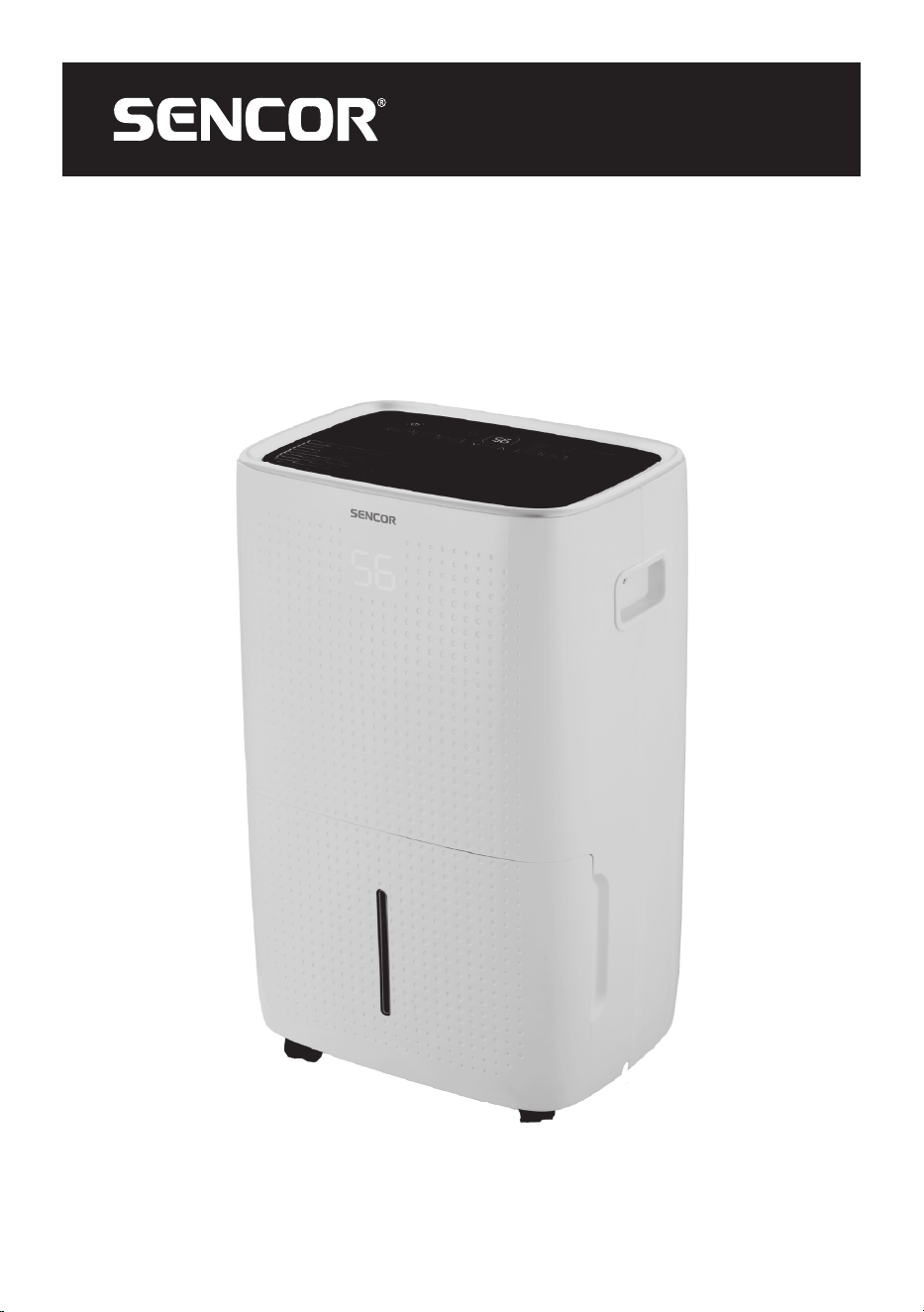
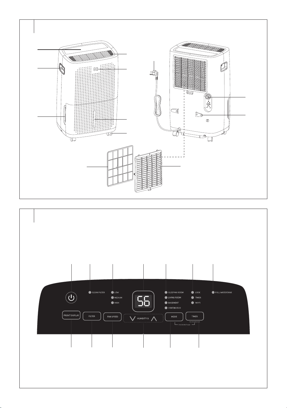
DESCRIPTION OF THE APPLIANCE
A1 Control panel
A2 Handles (located on both
sides)
A3 Condensate tank
A4 Air outflow
A5 Display of the front panel
A6 Water mark
A7 Castors
A8 Microfilter
A9 Air intake grille with microfilter
A10 Drain hose connection outlet
A11 Power cord holder
A12 Power cord
Without illustration: drain hose,
carbon filter
. . . . . . . . . . . . . . . . . . . . . . . . . . . . . . . . . . . . . . . . . . . . . . . . . . . . . . . . . . . . . . . . . . . .
DESCRIPTION OF THE CONTROL PANEL
B1 button is used to turn on/
off
B2 CLEAN FILTER indicator light
is used towarn you about
cleaning the carbon filter
B3 Speed indicator light (LOW –
MEDIUM – HIGH)
B4 Control panel display
B5 Operating mode indicator
lights
B6 Child lock (LOCK), timer and
Wi-Fi indicator lights
B7 FULL WATERTANK indicator
light is used toalert you to
afull condensate tank
B8 FRONT DISPLAY button is
used toswitch the display on
the front panel on/off
B9 FILTER button
B10 FAN SPEED button toset fan
speed
B11 HUMIDITY% buttons are
used toset the target humidity
B12 MODE button: used to select
the operating mode
B13 TIMER button is used toturn
the timer/child lock of the
control panel on/off
Note:
By holding down the MODE and TIMER buttons for
3seconds at the same time you reset the Wi-Fi.
. . . . . . . . . . . . . . . . . . . . . . . . . . . . . . . . . . . . . . . . . . . . . . . . . . . . . . . . . . . . . . . . . . . .
INTENDED USE
• The dehumidifier is used to reduce the humidity in theroom.
. . . . . . . . . . . . . . . . . . . . . . . . . . . . . . . . . . . . . . . . . . . . . . . . . . . . . . . . . . . . . . . . . . . .
BEFORE FIRST USE
• Before first use, remove the appliance and its accessories from the
packaging and discard all promotional labels and tags. Check that
neither the appliance nor any of its components is damaged.
• Pull out the condensate tank andremove the dehumidifier accessories
from the condensate tank.
• After unpacking, let the dehumidifier stand for 2 to 3hours to allow the
refrigerant in the cooling circuit to settle.
• Transport the dehumidifier only in the vertical position. We do not
recommend transporting it in ahorizontal position or tilting it.
• Wipe the outer surface of the dehumidifier with adry cloth.
Note:
Do not travel over carpets, door thresholds or other
obstacles with the wheels. This may lead to their damage.
Do not move the appliance when the condensate tank
is full.
. . . . . . . . . . . . . . . . . . . . . . . . . . . . . . . . . . . . . . . . . . . . . . . . . . . . . . . . . . . . . . . . . . . .
INSTALLATION LOCATION OF THE APPLIANCE
• Locate the appliance on an even, dry and stable surface within reach
of aproperly grounded power socket.
• Do not use the appliance outdoors.
• To ensure adequate air circulation, leave at least 20cm of free space
around andabove the appliance.
• Place the appliance in aroom where the temperature does not fall
below 5°C. Frost could form in the appliance if the temperature drops
below 5°C and the appliance would need to be defrosted.
• Do not locate the appliance in the vicinity of dryers, heating devices
and other sources of heat. Avoid location in direct sunlight.
• Do not use the appliance in locations where humidity could damage
books or other valuable items.
• The appliance must be used in aclosed room in order to ensure its
maximum effectiveness. Therefore, close the doors and windows of
the given room.
. . . . . . . . . . . . . . . . . . . . . . . . . . . . . . . . . . . . . . . . . . . . . . . . . . . . . . . . . . . . . . . . . . . .
OPERATING THE APPLIANCE
• The dehumidifier is used to reduce the humidity in aroom, e.g. to dry
out flooded cellars, rooms with increased humidity, etc. Do not use it
in areas where substances or objects are stored that require precise
temperature and humidity control in the room.
• Use the appliance at an ambient temperature between 7–35°C
and humidity between 30–80%. These values will ensure the most
effective operation of the dehumidifier.
• Always wait at least 3minutes before turning the appliance on again.
• Do not connect the appliance to apower socket to which another
appliance is already connected. We recommend connecting the
appliance to an independent circuit.
• Make sure that the condensate tank is correctly installed in the
appliance, otherwise the appliance may not function correctly.
. . . . . . . . . . . . . . . . . . . . . . . . . . . . . . . . . . . . . . . . . . . . . . . . . . . . . . . . . . . . . . . . . . . .
OPERATING THE APPLIANCE
• Make sure that the appliance is located in asuitable place and that it is
correctly assembled. Then insert the power plug into apower socket.
Asound alert will be heard. The dehumidifier is in stand-by mode.
Only the button will remain lit.
. . . . . . . . . . . . . . . . . . . . . . . . . . . . . . . . . . . . . . . . . . . . . . . . . . . . . . . . . . . . . . . . . . . .
POWER ON/OFF
• Press the button to turn on the dehumidifier. An audible warning
will sound once.
• When you first turn the dehumidifier on, it will automatically start in
the default dehumidification mode (default relative humidity 50%, low
fan speed). The display will show the humidity in the room and the fan
will start running.
• The next time you turn it on, the dehumidifier will start in the mode
andsettings (exceptfor the timer) in which you turned it off.
• If you need to switch off the appliance, press the
button. The
dehumidifier is now in stand-by mode.
EN
Smart Mobile Dehumidifier 60l Wi-Fi
User Manual
- 7 -
07/2025
2025, .
• If you need to turn the appliance off completely, pull the power plug
out of the power socket.
• The operation of the dehumidifier will stop automatically if the
condensate tank is full or incorrectly installed.
Note:
Warm air may escape from the air outlet during the
operation of the dehumidifier. This is normal.
. . . . . . . . . . . . . . . . . . . . . . . . . . . . . . . . . . . . . . . . . . . . . . . . . . . . . . . . . . . . . . . . . . . .
DEHUMIDIFICATION MODE (TARGET HUMIDITY
SETTING)
• This mode is suitable for normal everyday use, when the dehumidifier
will maintain the set target humidity in theroom.
• Turn on the dehumidifier.
• Use the
buttons to set the target humidity. It will briefly
appear on the display. The current humidity in the room will then be
displayed. You can set the target humidity from 35 to 80% at5%
intervals.
• Press the FAN SPEED button repeatedly to select the fan speed: low
( LOW indicator light will light up) – medium (MEDIUM indicator light
will light up) – high (HIGH indicator light will light up).
• When the sensor detects that the humidity in the room has reached
the set humidity, the operation of the dehumidifier is interrupted, the
compressor stops immediately, the fan will be inoperation for about
3 more minutes.
• As soon as the sensor detects that the humidity in theroom has
increased by 5%, the dehumidifier will start up again.
. . . . . . . . . . . . . . . . . . . . . . . . . . . . . . . . . . . . . . . . . . . . . . . . . . . . . . . . . . . . . . . . . . . .
SLEEPING ROOM MODE (DEHUMIDIFYING DURING
SLEEP)
• This mode is suitable fordehumidifying inbedrooms or other places
while you sleep. It is characterized by quiet operation so as not to
disturb sleep, andreduced performance where dehumidification is
slower but smooth. Power consumption is also optimized inthis mode.
• The fan speed andtarget humidity are set automatically andcannot
be changed. The target humidity is set to 55%.
• Turn on the dehumidifier.
• Press the MODE button repeatedly until the SLEEPING ROOM
indicator light lights up.
• If you need to exit this mode, select adifferent operating mode or use
the
buttons to set the target humidity.
. . . . . . . . . . . . . . . . . . . . . . . . . . . . . . . . . . . . . . . . . . . . . . . . . . . . . . . . . . . . . . . . . . . .
LIVING ROOM MODE (DEHUMIDIFYING INLIVING
ROOMS)
• This mode is suitable fordehumidification inliving rooms such
as living room, kitchen, etc. It is suitable for everyday use as it
maintains acomfortable humidity level (between 45–55% RH).
The fan speed adapts to the current air humidity, i.e. the higher the
humidity, the higher the fan setting the dehumidifier selects to quickly
andeffectively reduce the humidity in the room to acomfortable level.
• The fan speed andtarget humidity are set automatically andcannot
be changed. The target humidity is set to 50%.
• Turn on the dehumidifier.
• Press the MODE button repeatedly until the LIVING ROOM indicator
light lights up.
• If you need to exit this mode, select adifferent operating mode or use
the
buttons to set the target humidity.
. . . . . . . . . . . . . . . . . . . . . . . . . . . . . . . . . . . . . . . . . . . . . . . . . . . . . . . . . . . . . . . . . . . .
BASEMENT MODE (BASEMENT
DEHUMIDIFICATION)
• This mode is suitable fordehumidification incolder andwetter
areas, such as basements, garages or rooms with poor ventilation.
The dehumidifier is automatically set to maximum power to reduce
humidity as quickly as possible.
• The fan speed andtarget humidity are set automatically andcannot
be changed. The target humidity is set to 45%.
• Turn on the dehumidifier.
• Press the MODE button repeatedly until the BASEMENT indicator
light lights up.
• If you need to exit this mode, select adifferent operating mode or use
the
buttons to set the target humidity.
. . . . . . . . . . . . . . . . . . . . . . . . . . . . . . . . . . . . . . . . . . . . . . . . . . . . . . . . . . . . . . . . . . . .
CONTINUOUS mode (CONTINUOUS
DEHUMIDIFICATION)
• This mode is suitable forensuring constant removal of air humidity.
We recommend connecting the drain hose to ensure constant
drainage of condensate – see chapter “CONTINUOUS CONDENSATE
DRAINING VIA THE DRAIN HOSE” for more information.
• Turn on the dehumidifier.
• Press the MODE button repeatedly until the CONTINUOUS indicator
light lights up.
• If you need to exit this mode, select adifferent operating mode or use
the
buttons to set the target humidity.
. . . . . . . . . . . . . . . . . . . . . . . . . . . . . . . . . . . . . . . . . . . . . . . . . . . . . . . . . . . . . . . . . . . .
AUTO SHUT-OFF
• The dehumidifier is equipped with automatic turn-off feature after the
set time.
• While the dehumidifier is inoperation, press the TIMER button. The
display will flash.
• Use the
buttons to set the desired time for automatic
shut-off between 0.5 and 24hours. From 0.5 to 10hours set the auto
turn-off time by 0.5hour, from 10 to 24hours set the auto turn-off
time by 1hour.
• Wait for, the setting to be stored in memory and countdown starts. The
Timer indicator light will light up.
• Once the set time elapses, the humidifier will automatically turn off
and switch to standby mode.
• If you need to cancel the countdown, press the TIMER button and the
Timer indicator light will turn off.
. . . . . . . . . . . . . . . . . . . . . . . . . . . . . . . . . . . . . . . . . . . . . . . . . . . . . . . . . . . . . . . . . . . .
AUTO TURN-ON
• The dehumidifier is equipped with automatic turn-on feature after the
set time.
• While the dehumidifier is turned off, press the TIMER button. The
display will flash.
• Use the
buttons to set the automatic turn-on time
between 0.5 and 24hours. From 0.5 to 10hours set the auto turn-on
time by 0.5hour, from 10 to 24hours set the auto turn-on time by
1hour.
• Wait for, the setting to be stored in memory and countdown starts. The
Timer indicator light will light up.
• As soon as the set time has elapsed, the dehumidifier will turn on in
the set mode.
• If you need to cancel the countdown, press the TIMER button and the
Timer indicator light will turn off.
. . . . . . . . . . . . . . . . . . . . . . . . . . . . . . . . . . . . . . . . . . . . . . . . . . . . . . . . . . . . . . . . . . . .
CHILD LOCK
• The child lock allows you to lock the control panel to prevent
unwanted or sudden changes to the dehumidifier settings.
• Press and hold down the TIMER button for about 3seconds. The
LOCK indicator light will light up. No buttons will function.
• To deactivate the child safety lock, press andhold the TIMER button
again for 3seconds. The LOCK indicator light will turn off.
. . . . . . . . . . . . . . . . . . . . . . . . . . . . . . . . . . . . . . . . . . . . . . . . . . . . . . . . . . . . . . . . . . . .
- 8 -
07/2025
2025, .
DISPLAY OF THE FRONT PANEL
• Press the FRONT DISPLAY button to turn the display on/off on the
front panel. This displays the same data as the display on the control
panel:
• humidity in theroom (when the dehumidifier is inoperation);
• the set target humidity;
• the set time on timer;
• 20, if the relative humidity inthe room drops below 20%;
• 90, if the relative humidity inthe room exceeds 90%.
. . . . . . . . . . . . . . . . . . . . . . . . . . . . . . . . . . . . . . . . . . . . . . . . . . . . . . . . . . . . . . . . . . . .
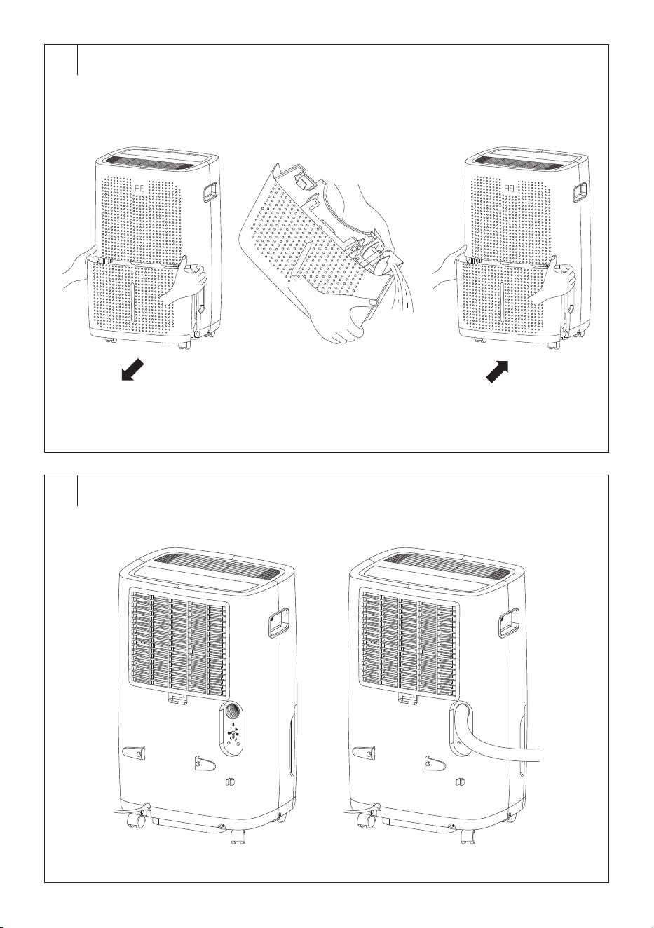
FULL TANK INDICATOR (Fig. C)
• If the condensate tank becomes full while the dehumidifier is in
operation, 3beeps will sound, the compressor and the fan will stop
running (the fan will stop running after afew minutes), an audible
warning will sound and the FULL WATERTANK indicator light will
flash on the control panel.
• Carefully pull the tank from the front part of the dehumidifier with both
hands and pour out the condensate. Wipe the tank clean with adry
cloth andplace it back in place. Make sure that the condensate tank is
inserted properly. If the tank is not inserted correctly, the dehumidifier
will not start.
• When the condensate tank is reinstalled, the dehumidifier will
automatically resume operation.
Note:
The fan will stop running after afew minutes if asound
alerts to afull tank.
Caution:
Do not place afull tank on an unstable or slanted
surface. There is arisk that the tank will overturn and
the contents will spill on the floor.
. . . . . . . . . . . . . . . . . . . . . . . . . . . . . . . . . . . . . . . . . . . . . . . . . . . . . . . . . . . . . . . . . . . .
CONTINUOUS CONDENSATE DRAINING VIA THE
DRAIN HOSE (Fig. D)
Adrain hose must be connected for continuous condensate drainage.
Follow these steps:
1. Unscrew the outlet plug on theback of the dehumidifier. Store the
cover in asafe place so you can put it back after use.
2. Insert the end of the drain hose into the outlet. The internal diameter of
the drain hose is 10mm. Make sure the hose end is properly inserted
to prevent condensate leakage.
3. Locate the free end of the hose so that the condensate can flow out
freely. The container or the place where the condensate is drained
must be lower than the outlet. Do not bend the hose excessively.
Guide it in such away that it cannot be trampled or tripped over.
Note:
When not using the drain hose for continuous draining of
condensate, remove it and wipe away any water.
Caution:
If the dehumidifier is not installed on aflat surface
or the drain hose is not installed correctly, the
dehumidifier will drain the condensate into the
container.
. . . . . . . . . . . . . . . . . . . . . . . . . . . . . . . . . . . . . . . . . . . . . . . . . . . . . . . . . . . . . . . . . . . .
AUTO DEFROST
• When frost accumulates on the evaporator coils, the compressor stops
running, but the fan stays on until the frost is removed.
• When fully defrosted, the compressor will automatically restart and
the dehumidification will resume.
. . . . . . . . . . . . . . . . . . . . . . . . . . . . . . . . . . . . . . . . . . . . . . . . . . . . . . . . . . . . . . . . . . . .
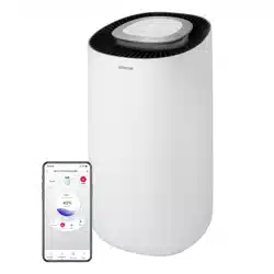
OPERATION USING THE MOBILE APPLICATION
• The dehumidifier can be controlled via the Sencor HOME application.
• Download the application to your smart phone, register yourself and
control the dehumidifier via the application.
• If you already have the application installed, add the dehumidifier
to your devices. It is necessary that the location services for the
Bluetooth function on the mobile phone are turned on.
Adding the Dehumidifier to the Device List via Bluetooth
You can add the dehumidifier to the Sencor HOME application by pairing
it via Bluetooth.
1. Switch on the Bluetooth function on your mobile phone.
2. Turn on the dehumidifier.
3. Reset Wi-Fi. Press the MODE and TIMER buttons for 3seconds until
the Wi-Fi indicator light starts flashing.
4. Open the application and click the “+” icon on the application'shome
page, then click “Add Device”.
5. The application itself will offer the device you are looking for.
6. Click on “Add Device” and the application will automatically guide you
through adding it.
Note:
If the Bluetooth connection fails or is not possible, make
sure there are no solid obstacles between your phone and
the convector and that the two devices are close together.
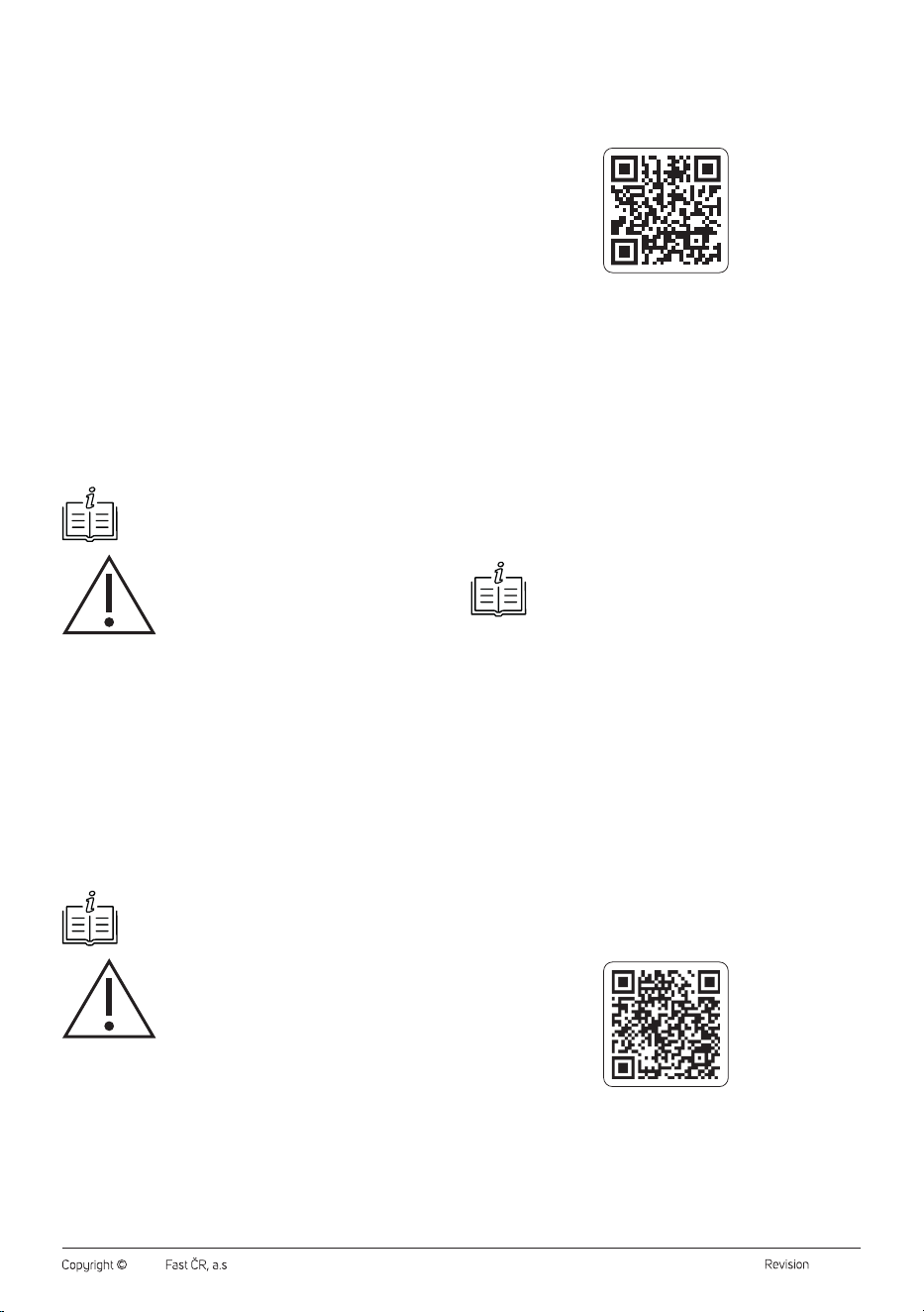
Adding the Dehumidifier to the Device List via aQR code
The dehumidifier can also be added to the Sencor HOME application
using the QR code provided below.
1. On the home screen of the application, click on the “+” icon and on the
Add device screen, click on the [−] icon in the top right corner.
2. You will be prompted toreset the device. Press the MODE and TIMER
buttons for 3seconds at the same time until the Wi-Fi indicator light
starts flashing. This means that the dehumidifier is ready to be paired.
Instructions can also be found on the application screen.
3. Inthe application, confirm that the (Wi-Fi) light is blinking, then click
“Next”.
4. On the next screen, you will be prompted toselect aWi-Fi network.
Select the network, enter your password andclick “Next”.
5. The process of adding the device starts. Wait until the convector is
paired.
6. In the device list on the main screen, click on the icon of the
dehumidifier to enter control interface.
QR Code for Adding the Control Panel of the Dehumidifier to
the Sencor HOME App
Manually Adding the Dehumidifier to the Device List
1. On the main screen, click on “Add Device” or the “+” in the top right
corner, and then click on “Add Device”.
2. Ascreen with appliance categories and alist of appliances will appear.
3. Click on “Dehumidifier” and select the dehumidifier model from the
product list.
4. You will be prompted toreset the device. Press the MODE and TIMER
buttons for 3seconds at the same time until the Wi-Fi indicator light
- 9 -
07/2025
2025, .
starts flashing. This means that the dehumidifier is ready to be paired.
Instructions can also be found on the application screen.
5. Inthe application, confirm that the (Wi-Fi) light is blinking, then click
“Next”.
6. On the next screen, you will be prompted toselect aWi-Fi network.
Select the network, enter your password andclick “Next”.
7. The process of adding the device starts. Wait until the convector is
paired.
8. In the device list on the main screen, click on the icon of the
dehumidifier to enter control interface.
Wi-Fi reset
• Press the MODE and TIMER buttons for 3seconds at the same time.
Note:
Always connect the dehumidifier to the 2.4GHz network. If
you are using a5GHz Wi-Fi network, switch to a2.4GHz
network.
. . . . . . . . . . . . . . . . . . . . . . . . . . . . . . . . . . . . . . . . . . . . . . . . . . . . . . . . . . . . . . . . . . . .
CLEANING AND MAINTENANCE
• Disconnect the power plug from the power socket before cleaning.
Note:
Do not use abrasive cleaning agents, solvents, etc. to clean
any parts of the appliance, as these could damage the
surface.
Caution:
To prevent the risk of electric shock, do not immerse
the appliance, power cable, or plug into water or any
other liquid.
Cleaning the Condensate Tank
• Empty out the condensate tank whenever you finish using the
appliance and wipe it using awiping cloth.
• To prevent undesirable bacteria, micro-organism or moulds from
multiplying inside the tank, clean it out at least once per month using
acloth dampened in lukewarm water with the addition of neutral
detergent. Then rinse it out thoroughly using clean water, wipe it dry
and insert it back into the appliance.
• Do not wash the condensate tank in adishwasher.
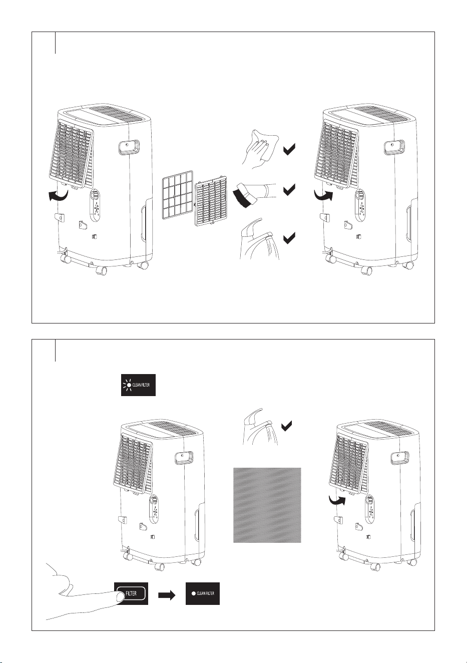
Cleaning the Protective Grille with Microfilter (Fig. E)
• Check and clean the protective grille at least once every two weeks, or
more often if you use the appliance every day.
• Remove the protective grille from thedehumidifier.
• You can remove the dust with soft cloth. If the filter grille is more
heavily soiled, you can vacuum up the dust and dirt using the
vacuum cleaner at its lowest setting with the upholstery brush
fitted. Alternatively, you can soak the grille in warm water (water
temperature maximum 40°C) anduse asoft sponge to clean it. Leave
in adry, shady and well-ventilated place to dry. Do not use adryer or
hair dryer to dry. Do not dry in direct sunlight. Make sure the grille is
completely dry before inserting it into the appliance.
• Install back in place.
Caution:
Do not use the appliance without the properly
installed protective grille. Do not wash the protective
filter grille in adishwasher.
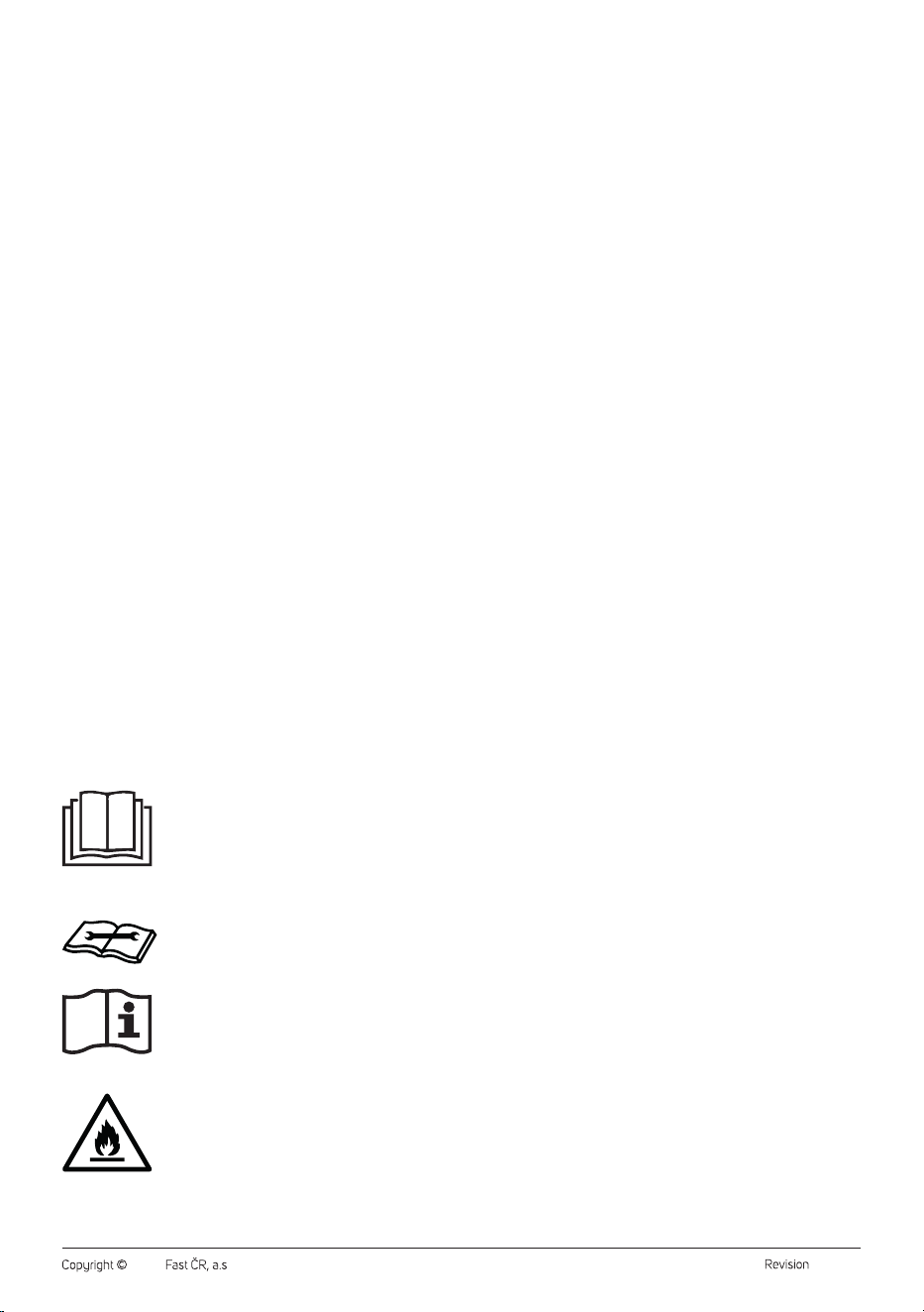
Cleaning the Carbon Filter (Fig. F)
• After approximately 250hours of operation, the CLEAN FILTER
indicator light will light up, alerting you to the need to clean the carbon
filter.
• Remove the protective grille from thedehumidifier andremove the
carbon filter.
• Check whether the carbon filter is damaged or worn. In such acase,
replace it with anew one.
• Wash the carbon filter in warm water (water temperature maximum
40°C) using asoft sponge to clean it. Leave in adry, shady and
well-ventilated place to dry. Do not use adryer or hair dryer to dry. Do
not dry in direct sunlight. Make sure the carbon filter is completely dry
before inserting it into the appliance.
• Insert the carbon filter andfit the protective grille.
• To reset the carbon filter counter, press the FILTER button, the CLEAN
FILTER indicator light will turn off.
Caution:
Do not use the dehumidifier without aproperly
inserted carbon filter or with adamaged or worn
carbon filter.
Cleaning the outer casing
• To clean the outer casing, use acloth slightly dampened with
lukewarm water and alittle dishwashing liquid. Make sure that water
does not enter into the vents. In the event that air inlet and outlet grilles
are only dusty, avacuum cleaner may be used to clean them.
. . . . . . . . . . . . . . . . . . . . . . . . . . . . . . . . . . . . . . . . . . . . . . . . . . . . . . . . . . . . . . . . . . . .
STORAGE
• When not using the appliance for an extended period of time,
disconnect the power plug from the power socket and clean it
according to the instructions provided above.
• Clean the tank no sooner than 24hours after turning the appliance
off since asmall amount of condensate may accumulate even during
this time.
• Store the appliance in adry, clean, and well-ventilated place away
from extreme temperatures and out of the reach of children or pets.
. . . . . . . . . . . . . . . . . . . . . . . . . . . . . . . . . . . . . . . . . . . . . . . . . . . . . . . . . . . . . . . . . . . .
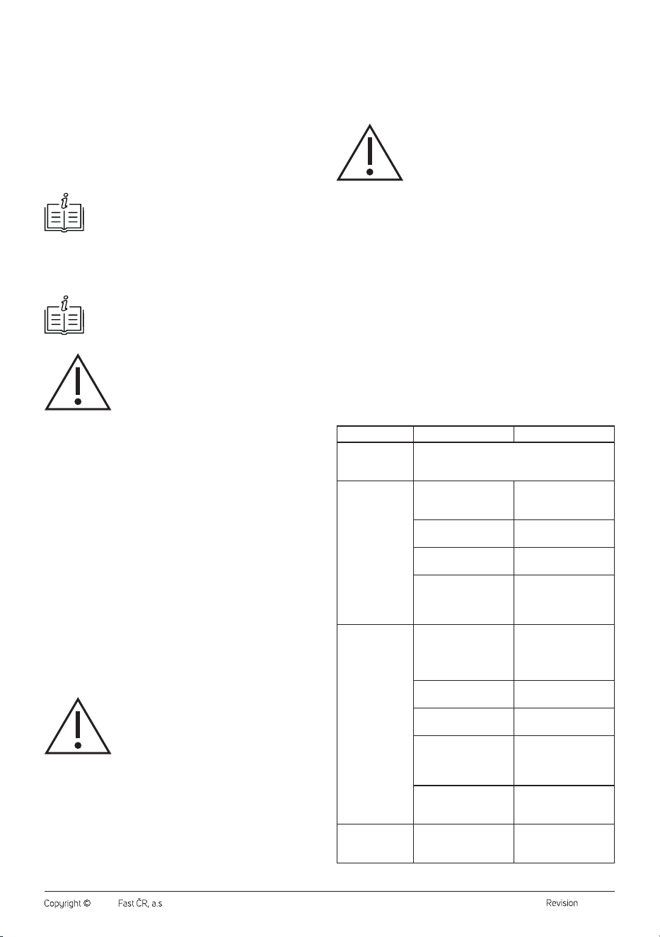
TROUBLESHOOTING
Problem Cause Solution
The dehumidifier
is emitting hot air.
This is normal. Dehumidified air passes through
aheating element, whereby the air is heated up
(without the cooling function).
The dehumidifier
didn't turn on.
The dehumidifier is not
connected to amains
socket.
Insert the power
plug into aproperly
grounded power socket.
Condensate tank is full.
Empty the condensate
tank.
The condensate tank is
not inserted correctly.
Insert the tank correctly
into the dehumidifier.
The dehumidifier is
located in aroom with
atemperature below
7°C or above 35°C.
Move the dehumidifier
to aroom with
atemperature above
7°C andbelow 35°C.
The dehumidifier
is not removing
humidity from the
room.
The air outlet or air
inflow is blocked.
Eliminate the cause of
the blockage of the air
outlet or inlet.
The protective grille
with carbon filter is dirty.
Clean the protective
grille with carbon filter.
High target humidity
is set.
Lower the set humidity.
Door or window is open.
Close the doors
andwindows of the
room where the
dehumidifier is located.
There is aclothes dryer
near the dehumidifier.
Place the dehumidifier
away from this
appliance.
The dehumidifier
does not exhaust
air.
The carbon filter is dirty. Clean the carbon filter.
- 10 -
07/2025
2025, .
Problem Cause Solution
The dehumidifier
has been
inoperation
for along
time andthe
dehumidification
result is not
satisfactory.
The room is too big.
Use the dehumidifier
inthe room of
therecommended
size – see the technical
specifications below.
Door or window is open.
Close the doors
andwindows of the
room where the
dehumidifier is located.
The dehumidifier
is noisy.
The dehumidifier is
located on an uneven
floor, is tilted, or is
located on an unstable
surface.
Place the dehumidifier
on aflat, firm and stable
surface.
The protective grille
with carbon filter is dirty.
Clean the protective
grille with carbon filter.
There is water on
the floor.
The drain hose is poorly
connected.
Check the connection of
the drain hose.
The drain hose is
damaged or worn.
Replace the drain hose.
In the event that the problem persists, or is not listed in the table above,
stop using the appliance and contact an authorised service centre.
. . . . . . . . . . . . . . . . . . . . . . . . . . . . . . . . . . . . . . . . . . . . . . . . . . . . . . . . . . . . . . . . . . . .
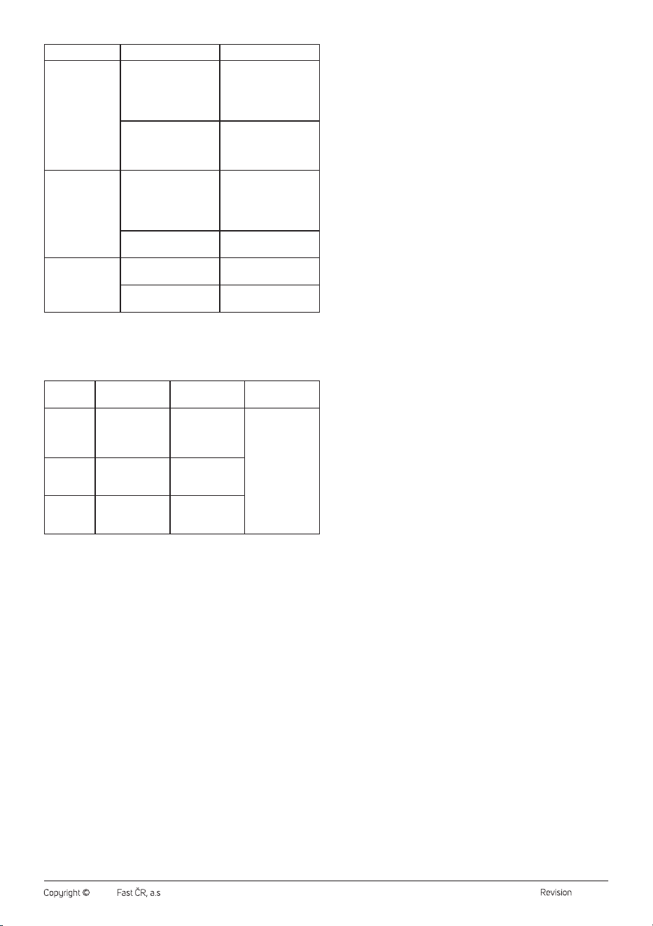
ERROR MESSAGES
Error
Message
Defect
description
Cause Solution
E1
Air outlet
temperature
sensor
malfunction
The sensor is
damaged.
Contact an
authorised
service centre.
E2
Temperature
coil sensor
malfunction
The temperature
sensor is
damaged.
EH
Fault on the
humidity sensor
The humidity
sensor is
damaged.
. . . . . . . . . . . . . . . . . . . . . . . . . . . . . . . . . . . . . . . . . . . . . . . . . . . . . . . . . . . . . . . . . . . .
TECHNICAL SPECIFICATIONS
Power supply ...........................................................................220–240 V~, 50 Hz
Dehumidification capacity ................................... 60 l / 24 h (30°C / 80% RH)
Rated power input ..............................................................................................800 W
Maximum power input .....................................................................................900 W
Rated current ...........................................................................................................3.5 A
Energy factor EEV .......................................................................................3.12 l/kWh
Starting current .......................................................................................................3.9 A
Fuse type and current value ...............................................................250 V, 3,15 A
Tank capacity ...............................................................................................................8 l
Refrigerant type and charge .............................................................. R290 / 150 g
GWP (global warming potential) .............................................................................. 3
CO
²
equivalent (t) ........................................................................................................... 0
Air flow volume ..............................................................................................270 m
3
/h
Max. suction pressure ....................................................................................0.6 MPa
Max. discharge pressure ................................................................................ 1.8 MPa
Maximum permitted water pressure.........................................................3.0 MPa
Noise level .................................42.7 / 44.4 / 48.7 dB(A) (LOW / MID / HIGH)
Dimensions ............................................................................ 393 × 297 × 623 mm
Weight .......................................................................................................................19 kg
Operating temperature ...................................................................................7–35°C
Recommended room size ....................................................................... 44–127 m
2
SENCOR hereby declares that the radio device type SDH6025WH
conforms to the 2014/53/EU directive. The full text of the EU Declaration
of Conformity is available at: www.sencor.eu.
. . . . . . . . . . . . . . . . . . . . . . . . . . . . . . . . . . . . . . . . . . . . . . . . . . . . . . . . . . . . . . . . . . . .
INSTRUCTIONS AND INFORMATION ON DISPOSAL
OF USED PACKAGING MATERIAL
Dispose of used packaging material at the designated municipal waste
disposal site.
. . . . . . . . . . . . . . . . . . . . . . . . . . . . . . . . . . . . . . . . . . . . . . . . . . . . . . . . . . . . . . . . . . . .
DISPOSAL OF USED ELECTRICAL AND ELECTRONIC
EQUIPMENT
Used electrical andelectronic products must not be disposed of in
ordinary municipal waste. To enable the proper disposal, renewal and
recycling of these products, deliver them to the designated collection
points. Alternatively, in some European Union states or other European
countries the products can be returned to the local retailer when buying
an equivalent new product. By disposing of this product correctly, you
help to conserve valuable natural resources and prevent any potential
adverse impact on the environment and human health that could result
from improper waste disposal. For more details, contact your local
authority or nearest collection point. Fines may be imposed for the
improper disposal of this type of waste as per national regulations.
For business entities in European Union States
If you wish to dispose of electrical and electronic equipment, please
request the necessary information from your retailer or supplier.
Disposal in other countries outside the European Union
To dispose of this product elsewhere, request the necessary information
on the correct disposal method from local authorities or your retailer.
. . . . . . . . . . . . . . . . . . . . . . . . . . . . . . . . . . . . . . . . . . . . . . . . . . . . . . . . . . . . . . . . . . . .
Changes to text and technical parameters are reserved.