JVC
SERVICE MANUAL
MODEL
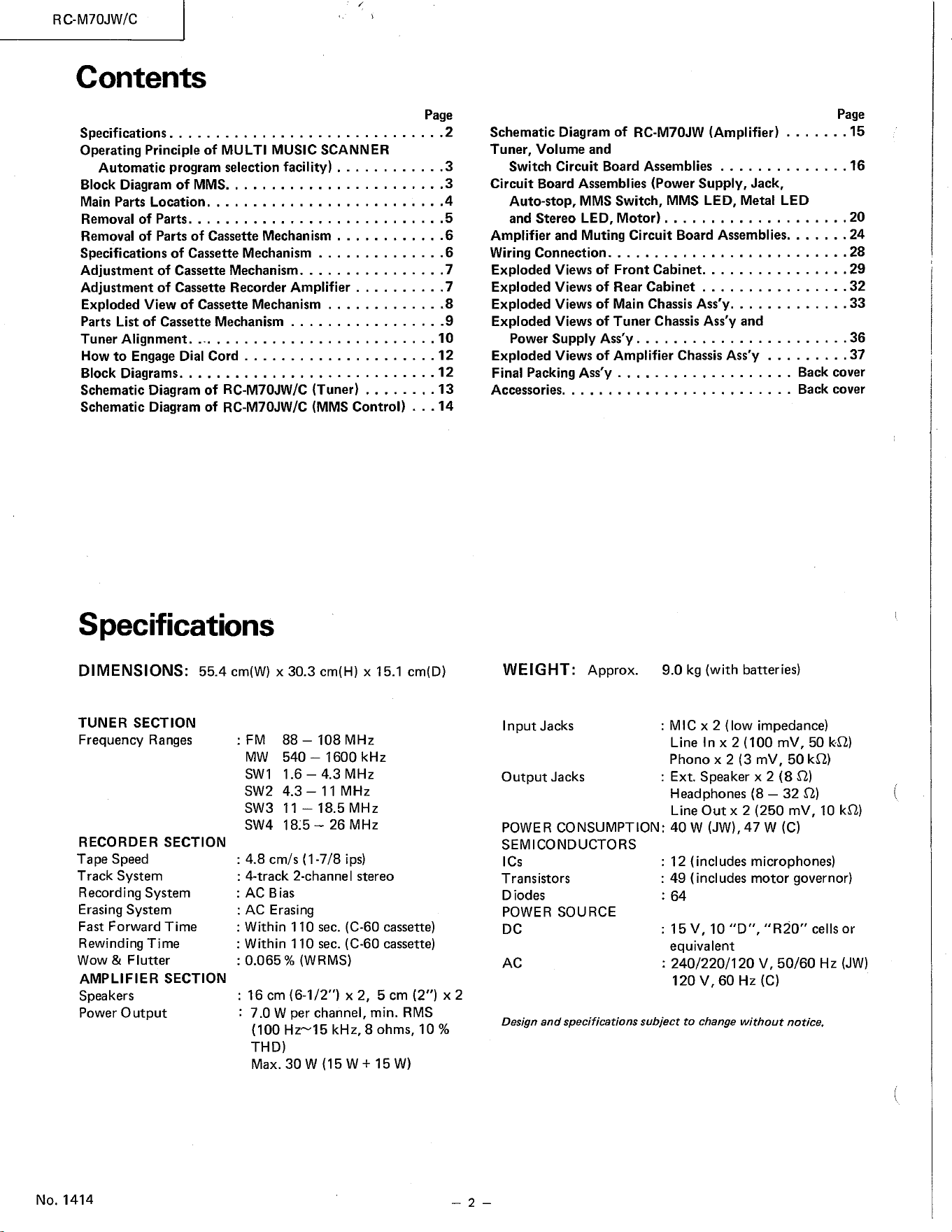
RC-M70JW/C
FM-MW-SWl-SW2-SW3-SW4
6-BAND STEREO
RADIO CASSETTE
RECORDER
No. 1414
March 1980
RC-M70JW/C
Contents
Specifications.. .
Operating Principle of MULTI MUSIC SCANNER
Automatic program selection facility) ....
Block Diagram of MMS..
Main Parts Location..... . .
Removal of Parts..
Removal of Parts of Cassette Mechanism .. ... ...
Specifications of Cassette Mechanism . ... .
Adjustment of Cassette Mechanism. .. ...... ... . 7
Adjustment of Cassette Recorder Amplifier . . . . . . . .
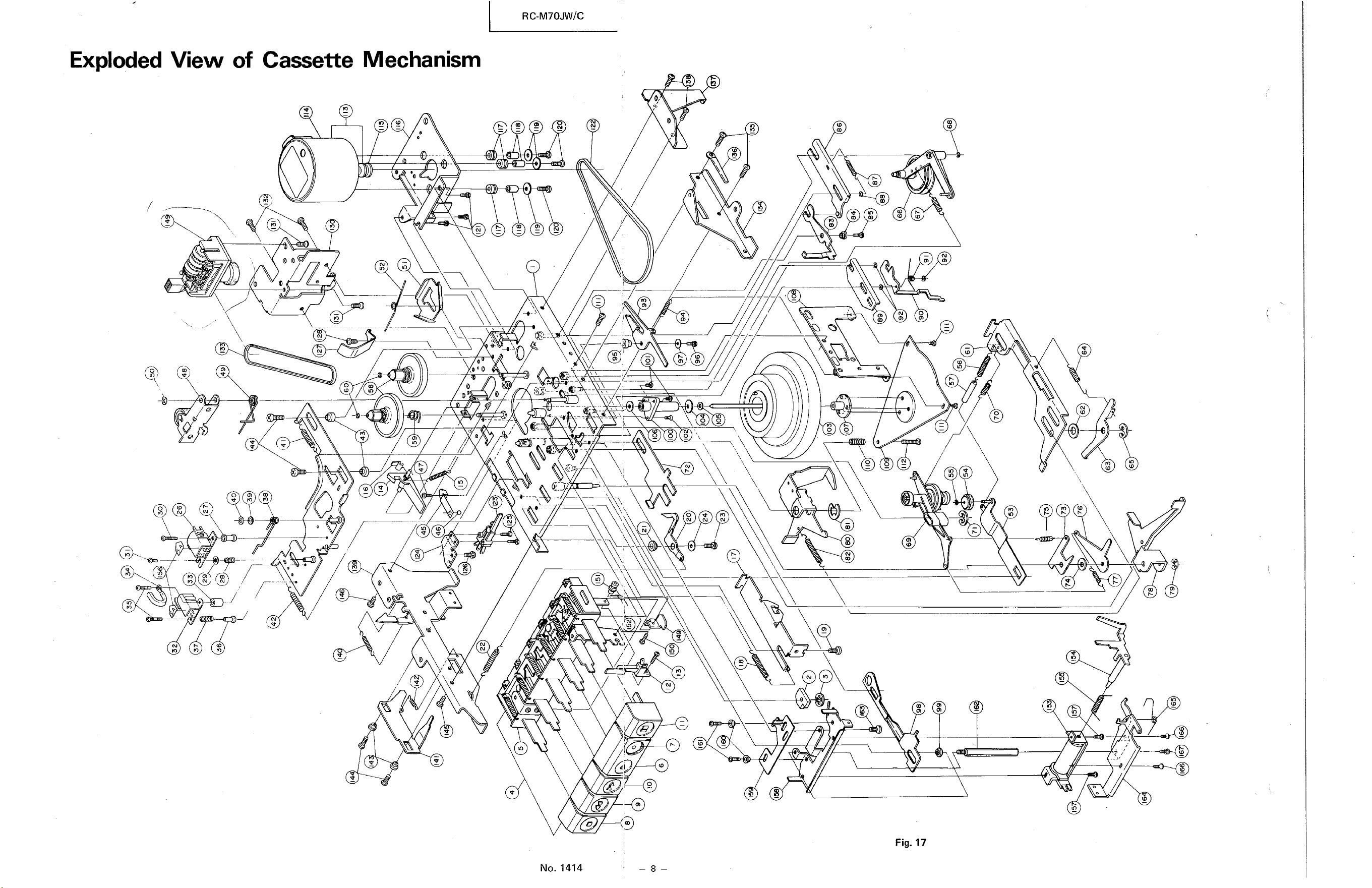
Exploded View of Cassette Mechanism
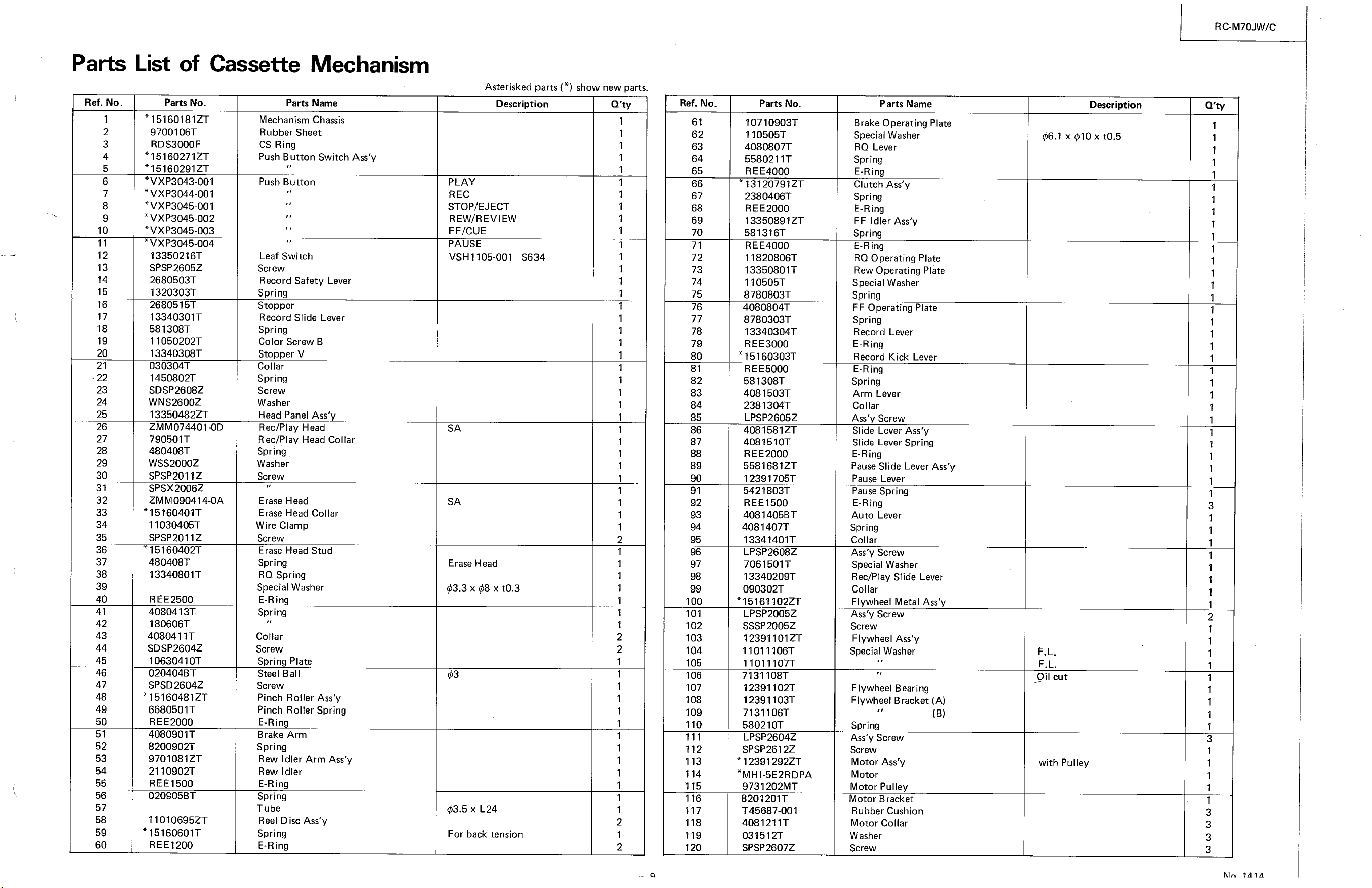
Parts List of Cassette Mechanism
Tuner Alignment. .. . .
How to Engage Dial Cord
Block Diagrams..
Schematic Diagram of RC-M70JW/C (Tuner) .
Schematic Diagram of RC-M70JW/C (MMS Control)
Specifications
DIMENSIONS: 55.4 cm(W) x 30.3 cm(H) x 15.1 cm(D)
Page
.3
.3
.4
.6
...6
.8
.9
.10
.12
...12
.13
.14
Page
Schematic Diagram of RC-M70JW (Amplifier) ... .... 15
Tuner, Volume and
.16Switch Circuit Board Assemblies .
Circuit Board Assemblies (Power Supply, Jack,
Auto-stop, MMS Switch, MMS LED, Metal LED
and Stereo LED, Motor) . .
. .20
Amplifier and Muting Circuit Board Assemblies... .... 24
.28
Wiring Connection. . .. . . ..
. .29
Exploded Views of Front Cabinet...... .. ... .
. 32
Exploded Views of Rear Cabinet .
. .33
Exploded Views of Main Chassis Ass'y... ..
Exploded Views of Tuner Chassis Ass'y and
.36
Power Supply Ass'y . . . .
.37
Exploded Views of Amplifier Chassis Ass'y .
Final Packing Ass'y
Accessories. ..
WEIGHT:
Input Jacks
Approx.
TUNER SECTION
Frequency Ranges
RECORDER SECTION
Tape Speed
Track System
Recording System
Erasing System
Fast Forward Time
Rewinding Time
Wow & Flutter
AMPLIFIER SECTION
Speakers
Power O utput
No. 1414
MW
SW 1
SW2
SW3
SW4
88 — 108 MHz
1600 kHz
540
1.6 - 4.3 MHz
4.3— 11 MHz
11 — 18.5 MHz
18.'5 — 26 MHz
: 4.8 cm/s (I -7/8 ips)
: 4-track 2-channel stereo
: AC Bias
AC Erasing
: Within 1 10 sec. (C-60 cassette)
: Within 1 10 sec. (C-60 cassette)
. 0.065% (WRMS)
: 16 cm (6-1/2") x 2, 5 cm (2") x 2
7.0 W per channel, min. RMS
(100 Hri5 kHz, 8 ohms, 10 %
THD)
Max. 30 W (15 w + 15 W)
Output Jacks
POWER CONSUMPTION: 40 W 47 W (C)
SEMICONDUCTORS
ICs
Transistors
D iodes
POWER SOURCE
DC
120 V, 60 Hz (C)
Design and specifications subject to change without notice.
Back cover
Back cover
9.0 kg (with batteries)
MIC x 2 (low impedance)
Line In x 2 (100 mv, 50 1<0)
Phono x 2 (3 mV, 50 kO)
. Ext. Speaker x 2 (8 0)
Headphones (8 — 32 0)
Line Out x 2 (250 mv, 10 k0)
12 (includes microphones)
• 49 (includes motor governor)
: 64
: 15 V, 10 "D", "R20" cells or
equivalent
240/220/120 V, 50/60 Hz (JW)
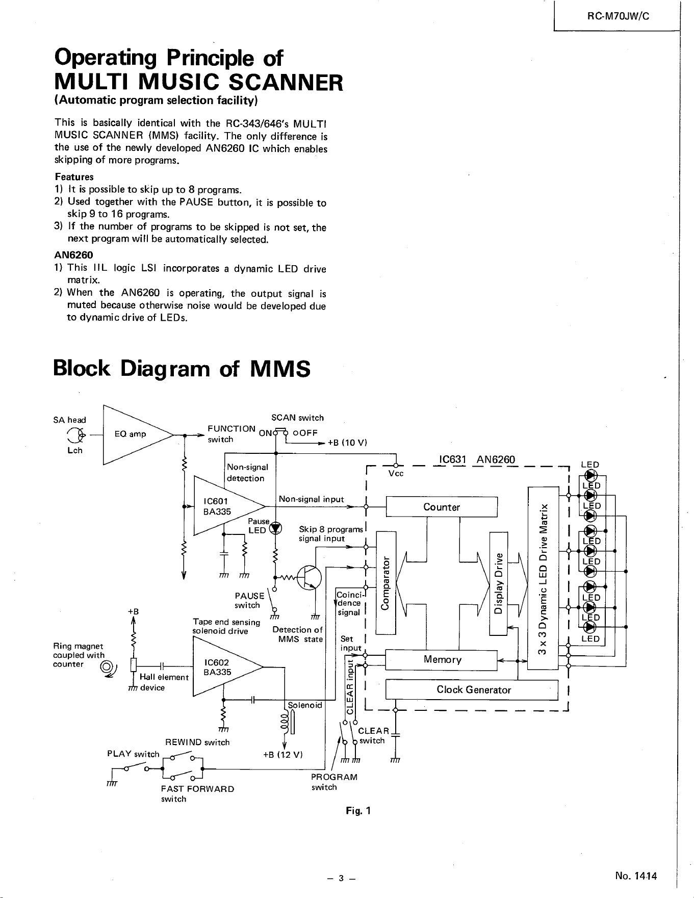
Operating Principle of
MULTI MUSIC SCANNER
(Automatic program selection facility)
This is basically identical with the RC-343/646's MULTI
MUSIC SCANNER (MMS) facility. The only difference is
the use of the newly developed AN6260 IC which enables
skipping of more programs.
Features
1) It is possible to skip up to 8 programs.
2) Used together with the PAUSE button, it is possibleto
skip 9 to 16 programs.
3) If the number of programsto be skipped is not set,the
next program will be automatically selected.
AN6260
I) This IIL logic LSI incorporates a dynamic LED drive
matrix.
2) When the AN6260 is operating, the output signal is
muted becauseotherwise noise would be developed due
to dynamic drive of LEDs.
Block Diagram of MMS
SA head
Lch
Ring magnet
coupled with
counter O
EQ amp
FUNCTION
ON
switch
Non-signal
detection
IC601
BA335
Pause
LED
PAUSE
switch
Tape end sensing
solenoid drive
IC602
BA335
SCAN switch
O OFF
+B (10 V)
Non-signal input
Skip 8 programs
signal input
IC631
V cc
Counter
Memory
AN6260
element
device
REWIND switch
PLAY switch
FAST FORWARD
swi tch
Detection of
MMS State
Solenoid
Coinci
dence
signal
Set
input
CLEAR
switch
Clock Generator
+B (1.2 V)
PROGRAM
switch
Fig. 1
RC-M70JW/C
LED
LED
LED
LED
LED
LED
No. 14.14
RC-M70JW/C
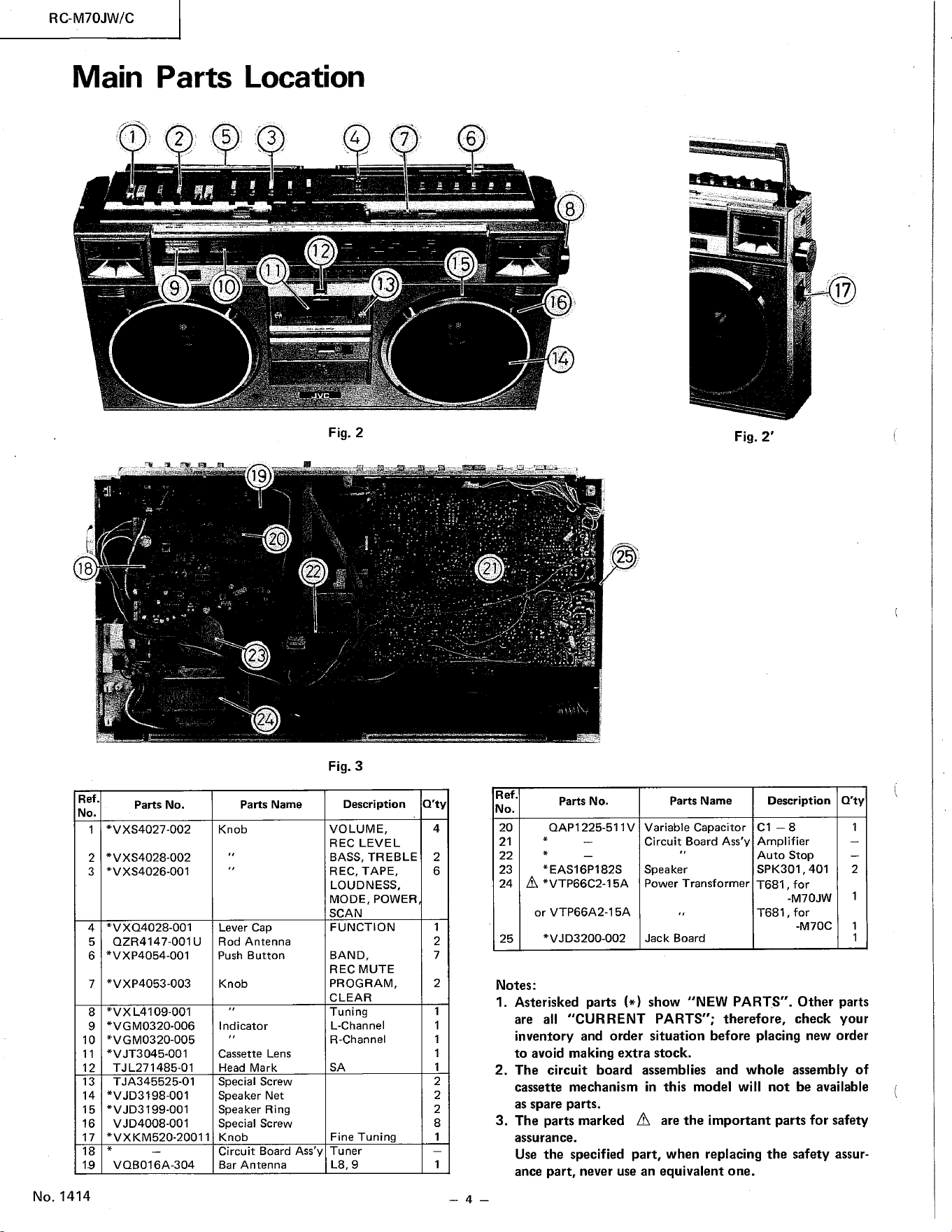
Main
Parts Location
7 6
8
16
14
18
Ref.
No.
2
3
4
5
6
7
8
9
10
11
12
13
14
15
16
17
18
19
No. 1414
2
9
Parts No.
*VXS4027-002
*VXS4028-002
*VXS4026-001
*VXQ4028-001
QZR4147-001 U
*VXP4054-001
*VXP4053-003
*VXL4109-001
*VGM0320-006
*VGM0320-005
*VJT3045-001
TJL271485-01
TJA345525-01
*VJD3198-001
*VJD3199-001
V JD4008-001
*VXKM520-20011
VQB016A-304
5
10
3
4
12
Fig. 2
22
Fig. 3
13
17
Fig. 2'
19
23
Description
VOLUME,
REC LEVEL
BASS, TREBLE
REC, TAPE,
LOUDNESS,
MODE, POWER
SCAN
FUNCTION
BAND,
REC MUTE
PROGRAM,
CLEAR
Tuning
L-Channel
R -Channel
SA
Fine Tuning
Tuner
Q'ty
4
2
6
2
7
2
2
2
8
1
21
Ref.
No.
20
21
22
23
24
25
2
Parts No.
OAPI 225-511 V
*EAS16P182S
A *VTP66C2-15A
or VTP66A2-1
*VJD3200-002
Parts Name
Knob
Lever Cap
Rod Antenna
Push Button
Knob
Indicator
Cassette Lens
Head Mark
Special Screw
Speaker Net
Speaker Ring
Special Screw
Knob
Circuit Board Ass'y
Bar Antenna
Parts Name
Variable Capacitor
Circuit Board Ass'y
Speaker
Power Transformer
Jack Board
Description Q'ty
Ampl ifier
Auto Stop
SPK301 , 401
T681 , for
-M70JW
T681 , for
-M70C
2
Notes:
I.
2.
3.
Asterisked parts show "NEW PARTS". Other parts
are all "CURRENT PARTS"; therefore, check your
inventory and order situation before placing new order
to avoid making extra stock.
The circuit board assemblies and whole assembly of
cassette mechanism in this model will not be available
as spare parts.
The partsmarked A arethe important partsfor safety
assurance.
Use the specified part, when replacing the safety assur-
ance part, never use an equivalent one.
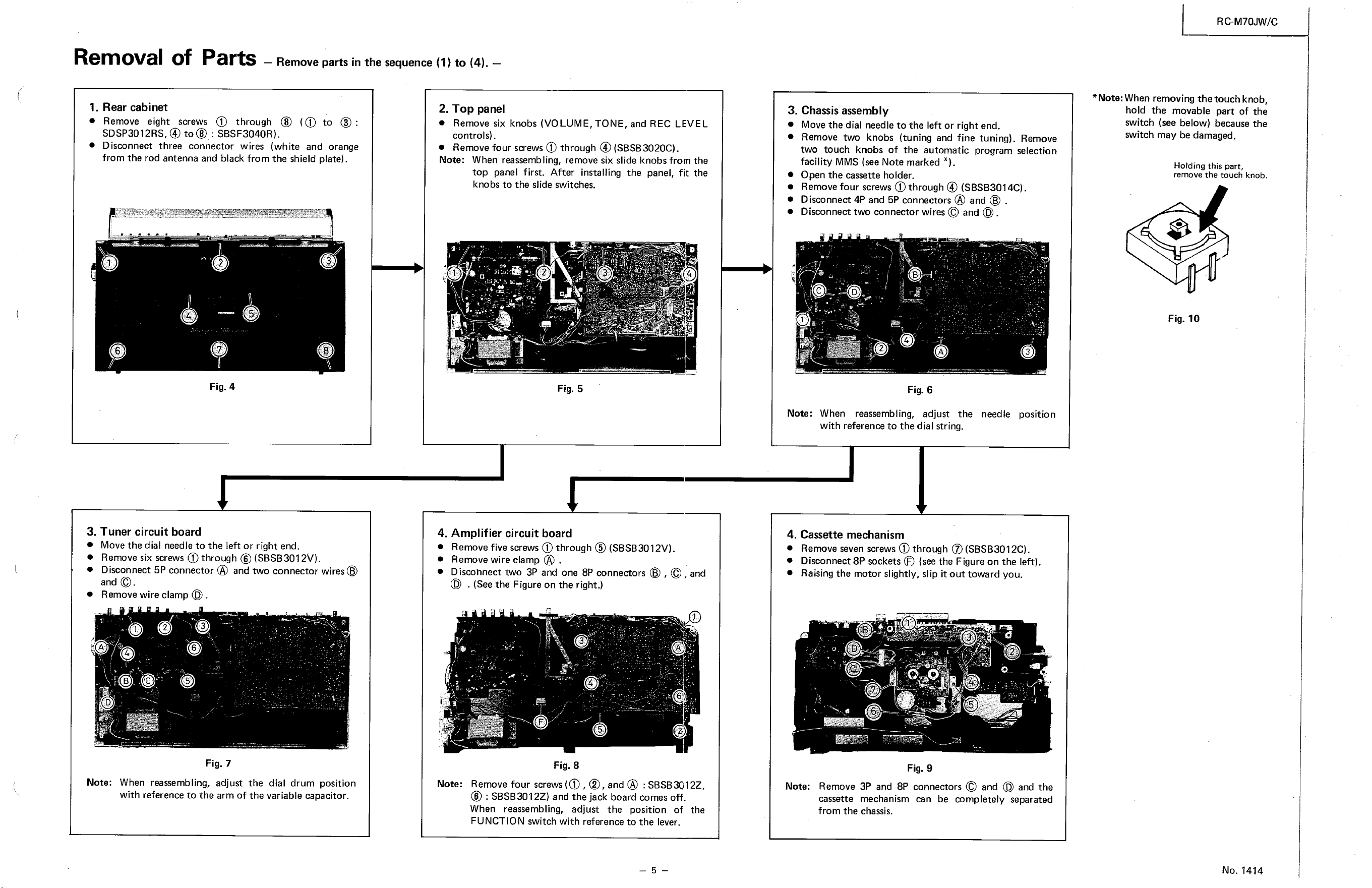
Removal Of Parts —Removepartsinthesequence(1)to(4).
1.
Rear cabinet
Remove eight screws 0) through @ (0) to @ :
SDSP3012RS, @ : SBSF3040R).
Disconnect three connector wires (white and orange
from the rod antenna and black from the shield plate).
2. Top panel
• Remove six knobs (VOLUME, TONE, and REC LEVEL
controls).
Removefour screws through @ (SBSB3020C).
Note: When reassemb ling, remove six slide knobs from the
top panel first. After installing the panel, fit the
knobs to the slide switches.
2
Fig. 4
3
2
c.
Fig. 5
4. Amplifier circuit board
4
3. Tuner circuit board
Move the dial needle to the left or right end.
Removesix screwsO) through @ (SBSB3012V).
Disconnect5P connector@ and two connector wires@
and O.
Removewire clamp .
Fig. 7
Note: When reassembling, adjust the dial drum position
with referenceto the arm of the variable capacitor.
Removefive screws(j) through @ (SBSB3012V).
Remove wire clarnp @
Disconnecttwo 3P and one 8P connectors@ , O , and
(D . (Seethe Figureontheright.)
Fig. 8
3. Chassis assembly
Move the dial needle to the left or right end.
Remove two knobs (tuning and fine tuning). Remove
two touch knobs of the automatic program selection
facility MMS (see Note marked * ).
Open the cassette holder.
Remove four screws @through @ (SBSB3014C).
Disconnect4P and 5Pconnectors@ and @
Disconnecttwo connector wiresO and (D .
Fig. 6
Note: When reassembling, adjust the needle position
with reference to the dial string.
4. Cassette mechanism
Removesevenscrews(j) through (SBSB3012C).
Disconnect8Psockets(b (seethe Figureon the left).
Raising the rnotor slightly, slip it out toward you.
Fig. 9
Note:
Removefour screws(O , @, and@ : SBSB3C12Z,
@ : SBSB3012Z)and the jack board comesoff.
When reassembling, adjust the position of the
FUNCTION switch with reference to the lever.
—5—
Note:
Remove 3P and 8P connectorsO and (D and the
cassette mechanism can be completely separated
from the chassis.
RCM70JW/C
*Note: Whenremovingthe touch knob,
hold the movable part of the
switch (see below) because the
switch may be damaged.
Holding this part,
remove the touch knob.
Fig. 10
No. 1414
RC-M70JW/C
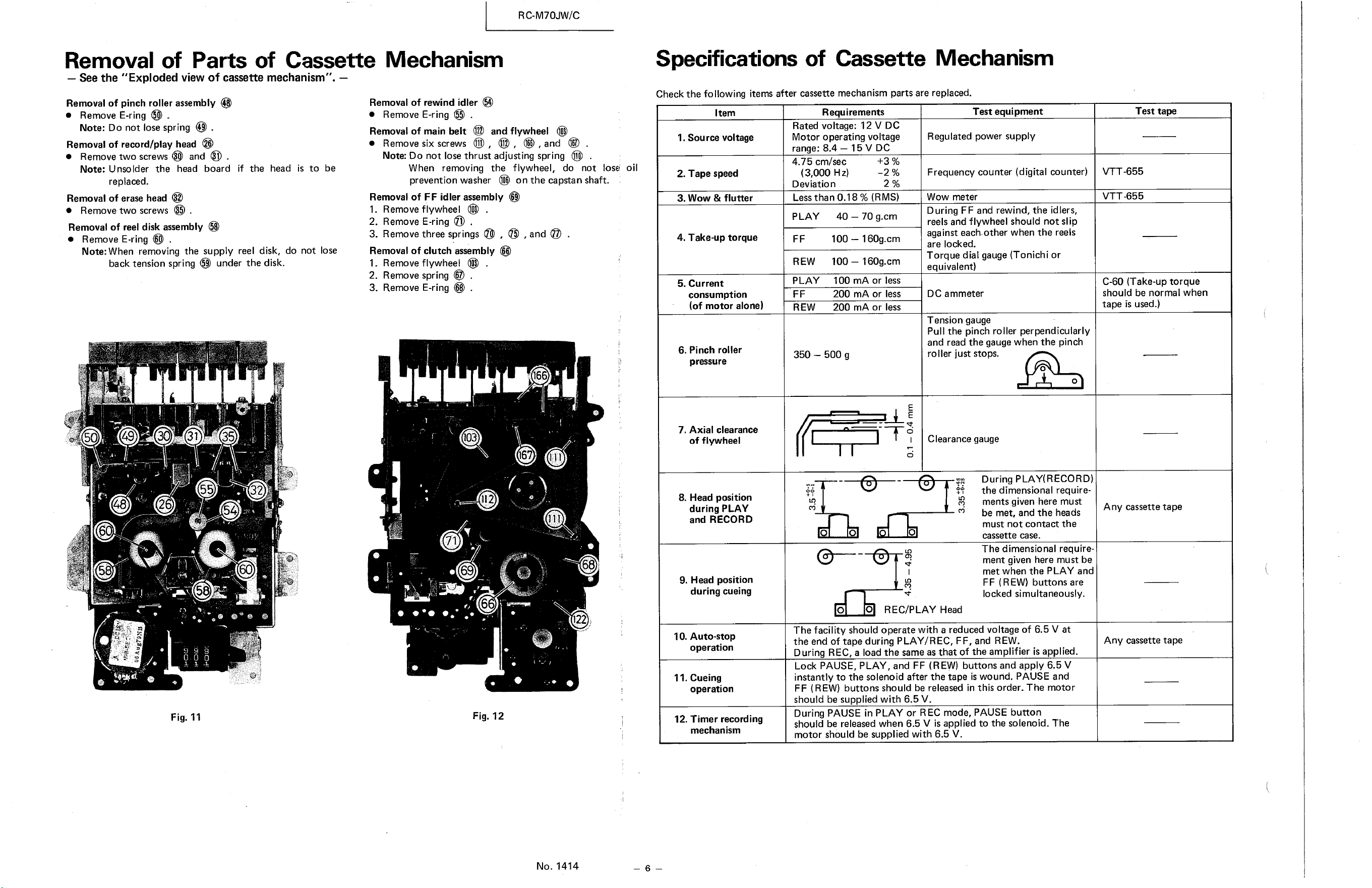
Removal of Parts of Cassette Mechanism
350 —500 g
— See the "Exploded view of cassette mechanism".
Specifications of Cassette Mechanism
Check the following items after cassettemechanism parts are replaced.
Removal of pinch roller assembly @
• Remove E-ring
Note: Do not losespring @
Removal Of record/play head
@ and O .• Remove two screws
Note: Unsolder the head board
replaced.
Removalof erasehead@
• Remove two screws
Removal of reel disk assembly
• Remove E-ring @
Note: When removing the supply
if the
head is
to
be
Removal of rewind idler
• Remove E-ring $
RemovalOf main belt @ and flywheel @
• Removesix screws , @ , @ , and @
Note: DO not lose thrust adjusting spring @
When removing the flywheel, do not lose
prevention washer on the capstan shaft.
Removalof FF idler assembly @
I. Remove flywheel
2. Remove E-ring
3. Removethree springs @ , @ , and
Removalof clutch assembly@
I. Remove flywheel
2. Remove spring
3. RemoveE-ring @
166
103
16
oil
Item
1. Source voltage
2. Tape speed
3. Wow & flutter
4. Take-up torque
5. Current
consumption
(of motor alone)
6. Pinch roller
pressure
7. Axial clearance
of flywheel
8. Head position
during PLAY
and RECORD
9. Head position
during cueing
10. Auto-stop
operation
I I. Cueing
operation
12. Timer recording
mechanism
Requirements
Rated voltage: 12 V DC
Motor operating voltage
range: 8.4 — 15 V DC
4.75 cm/sec
(3,000 Hz)
Deviation
+3%
2%
Less than 0.18% (RMS)
reel disk, do not lose
PLAY
REW
PLAY
REW
40 — 70 g.cm
100 — 160g.cm
100 — 160g.cm
100 mA or less
200 mA or less
200 mA or less
Test equipment
Regulated power supply
Frequency counter (digital counter)
Wow meter
During FF and rewind, the idlers,
reels and flywheel should not slip
against each-other when the reels
are locked.
Torque dial gauge (Tonichi or
equivalent)
DC ammeter
Tension gauge
Pull the pinch roller perpendicularly
and read the gauge when the pinch
roller just stops.
o
o
Clearance gauge
Test tape
VTT$55
VTT$55
C-60 (Take-up torque
should be normal when
tape is used.)
backtension spring (59)under the disk.
31
35
6
58
55
5
32
60
112
71
69
6
Fig. 12
Ill
122
No. 1414
During PLAY(RECORD)
the dimensional require-
ments given here must
Any cassette tape
be met, and the heads
must not contact the
cassette case.
The dimensional require-
ment given here must be
met when the PLAY and
FF (REW) buttons are
locked simultaneously.
Any cassette tape
o o
o
Fig. 11
o O REC/PLAY Head
The facility should operate with a reduced voltage of 6.5 V at
the end of tape during PLAY/REC, FF, and REW.
During REC, a load the sameas that of the amplifier is applied.
Lock PAUSE, PLAY , and FF (REW) buttons and apply 6.5 V
instantly to the solenoid after the tape is wound. PAUSE and
FF (REW) buttons should be released in this order. The motor
should be supplied with 6.5 V.
During PAUSE in PLAY or REC mode, PAUSE button
should be released when 6.5 V is applied to the solenoid. The
motor should be supplied with 6.5 V.
RC-M70JW/C
Recorder Amplifier
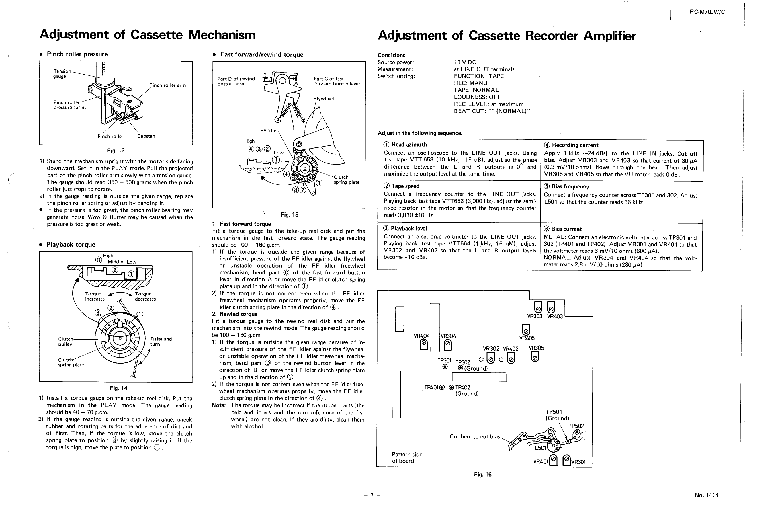
Adjustment of Cassette
• Pinch roller pressure
Tensio
gauge
Mechanism
• Fast forward/rewind torque
Conditions
Source power:
Measurement:
Switch setting:
Pinch roller
pressure spring
Pinch roller arm
Capstan
Part D of rewind
button lever
High
4
o
4
Fig. 15
Part C of fast
forward button lever
Flywheel
Clutch
spring plate
Adjustment of Cassette
Fig. 16
15 V DC
at LINE OUT terminals
FUNCTION: TAPE
REC: MANU
TAPE: NORMAL
LOUDNESS: OFF
REC LEVEL: at maximum
BEAT CUT: "1 (NORMAL)"
FF idler
Pinch roller
Fig. 13
I) Stand the mechanism upright with the motor sidefacing
downward. Set it in the PLAY mode. Pull the projected
part of the pinch roller arm slowly with a tension gauge.
The gauge should read 350 — 500 grams when the pinch
roller just stops to rotate.
2) If the gauge reading is outside the given range, replace
the pinch roller spring or adjust by bending it.
• If the pressure is too great, the pinch roller bearing may
generate noise. Wow & flutter may be caused when the
pressure is too great or weak.
• Playback torque
High
Middle Low
Torque Torque
Adjust in the following sequence.
(j) Head azimuth
Connect an oscilloscope to the LINE OUT jacks. Using
test tape VT T-658 (10 kHz, -15 dB), adjust so the phase
difference between the L and R outputs is 00 and
maximize the output level at the sarne tirne.
@ Tapespeed
Connect a frequency counter to the LINE OUT jacks.
Playing back test tape VTT656 (3,000 Hz), adjust the semi-
fixed resistor in the motor so that the frequency counter
reads 3D10 Hz.
@ Playbacklevel
Connect an electronic voltmeter to the LINE OUT jacks.
Playing back test tape VTT664 (l kHz. 16 rnM), adjust
VR302 and VR402 so that the L and R output levels
@ Recordingcurrent
Apply 1 kHz (-24 dBs) to the LINE IN jacks. Cut off
bias. Adjust VR303 and VR403 so that current of 30 gA
(0.3 mV/IO ohms) flows through the head. Then adjust
VR305 and VR405 so that the VU meter reads O dB.
@ Biasfrequency
Connect a frequency counter acrossTP301 and 302. Adjust
L501 so that the counter reads 66 kHz.
@ Biascurrent
METAL: Connect an electronic voltmeter across TP301 and
302 (TP401 and TP402). Adjust VR301 and VR401 so that
the voltmeter reads6 mV/IO ohms (600 g,A).
NORMAL: Adjust VR304 and VR404 so that the volt-
meter reads2.8 mV/IO ohms (280 gA).
increases
2
3
decreases
1
Raise and
tur n
1. Fast forward torque
Fit a torque gauge to the take-up reel disk and put the
mechanism in the fast forward state. The gauge reading
should be 100 — 160 g.cm.
1) If the torque is outside the given range because of
insufficient pressure Of the FF idler against the flywheel
or unstable operation of the FF idler freewheel
mechanism, bend part O of the fast forward button
lever in direction A or move the FF idler clutch spring
plate up and in the direction of @ .
2) If the torque is not correct even When the FF idler
freewheel mechanism operates properly, move the FF
idler clutch spring plate in the direction of @.
2. Rewind torque
Fit a torque gauge to the rewind reel disk and put the
mechanism into the rewind mode. The gaugereading should
be 100 — 160 g.cm.
1) If the torque is outside the given range because of in-
sufficient pressure of the FF idler against the flywheel
or unstable operation of the FF idler freewheel mecha-
nism, bend part (D of the rewind button lever in the
direction of B or rnove the FF idler clutch spring plate
up and in the direction Of(j)
2) If the torque is not correct even when the FF idler free-
wheel mechanism operates properly, move the FF idler
clutch spring plate in the direction of @ .
Note: The torque may be incorrect if the rubber parts (the
belt and idlers and the circumference of the fly-
wheel) are not clean. If they are dirty, clean them
with alcohol.
become —10 dBs.
VR404
Clutch
pulley
Clut
VR303 VR403
VR405
VR302 VR402 VR305
spring plate
Fig. 14
I) Install a torque gaugeon the take-up reel disk. Put the
mechanism in the PLAY mode. The gauge reading
should be 40 — 70 g.cm.
2) If the gauge reading is outside the given range, check
rubber and rotating parts for the adherence of dirt and
oil first. Then, if the torque is low, move the clutch
springplateto position@ by slightlyraisingit. If the
torque is high, movethe plate to position (D
TP301TP302
@ @(Ground)
TP401@ @TP402
(Ground)
TP501
(Ground)
TP502
Cut here to cut bias
Pattern side
Of board
1501
VR401
No. 1414
12
13
35
32
37
36
42
22
15
15
14
18
19
34
33
29
31
26
40
39
44
38
43
16
14
59
47
45
46
12
12
49
60
58
12
95
12
161
158
15
21
20
24
69
71
53
75
74
76,
77
78
79
14
13
131
121
n7
119
12
83
84
87
88
67
92
113
115
116
117
118
119
135
86
72
110
112
55
63
65
10
107
70
62
93
101
97
94
96
92
90
56
98
15
Parts List of Cassette Mechanism
Asterisked parts (* ) show new parts.
Ref. No.
1
2
3
4
5
6
7
8
9
10
11
12
13
14
15
16
17
18
19
20
21
22
23
24
25
26
27
28
29
30
31
32
33
34
35
36
37
38
39
41
42
43
44
45
46
47
48
49
50
51
52
53
54
55
56
57
58
59
60
Parts No.
*15160181ZT
9700106T
RDS3000F
*15160271ZT
*15160291ZT
*VXP3043-001
*VXP3044-001
*VXP3045-001
*VXP3045-002
*VXP3045-003
VXP3045-004
13350216T
SPSP2605Z
2680503T
1320303T
2680515T
13340301T
581308T
11050202T
13340308T
030304T
1450802T
SDSP2608Z
WNS2600Z
13350482ZT
ZMM074401-OD
790501T
480408T
WSS2000z
SPSP2011Z
SPSX2006Z
ZMM090414-OA
*15160401T
11030405T
SPSP2011Z
15160402T
480408T
13340801T
REE2500
4080413T
180606T
408041 IT
SDSP2604Z
1063041 OT
020404BT
SPSD2604Z
*15160481ZT
6680501T
REE2000
4080901T
8200902T
9701081ZT
2110902T
REE1500
020905BT
11010695ZT
*15160601T
REE1200
Parts Name
Mechanism Chassis
Rubber Sheet
CS Ring
Push Button Switch Ass'y
Push Button
Leaf Switch
Screw
Record Safety Lever
Spring
Stopper
Record Slide Lever
Spring
Color Screw B
Stopper V
Collar
Spring
Screw
W asher
Head Panel Ass'
Rec/Play Head
Rec/Play Head Collar
Spring
Washer
Screw
Erase Head
Erase Head Collar
Wire Clamp
Screw
Erase Head Stud
Spring
RQ Spring
Special Washer
E-Ring
Spring
Collar
Screw
Spring Plate
Steel Ball
Screw
Pinch Roller Ass'y
Pinch Roller Spring
E-Ring
Brake Arm
Spring
Rew Idler Arm Ass'y
Rew Idler
E-Ring
Spring
T ube
Reel Disc Ass'y
Spring
E-Ring
Description
PLAY
REC
STOP/EJECT
REW/REVIEW
F F[CUE
PAUSE
VSHI 105-001
SA
SA
Erase Head
S634
43.3 X +8 X to.3
+3
+3.5 x L24
For back tension
Q'ty
1
1
1
1
1
1
1
1
1
1
1
1
1
1
1
1
1
1
1
1
1
1
1
1
1
1
1
1
2
1
1
1
1
1
2
2
1
1
1
1
1
1
1
1
1
1
2
1
2
Ref. No.
61
62
63
64
65
66
67
68
69
70
71
72
73
74
75
76
77
78
79
80
81
82
83
84
85
86
87
88
89
90
91
92
93
94
95
96
97
98
99
100
101
102
103
104
105
106
107
108
109
110
111
112
113
114
115
116
117
118
119
120
Parts No.
10710903T
110505T
4080807T
558021 IT
REE4000
13120791ZT
2380406T
REE2000
13350891ZT
581316T
REE4000
11820806T
13350801T
110505T
8780803T
4080804T
8780303T
13340304T
REE3000
*15160303T
REE5000
581308T
4081503T
2381304T
LPSP2605Z
4081581ZT
4081510T
REE2000
5581681ZT
12391705T
5421803T
REE1500
4081405BT
4081407T
13341401T
LPSP2608Z
7061501T
13340209T
090302T
15161102ZT
LPSP2005Z
SSSP2005Z
12391101ZT
11011106T
11011107T
7131108T
12391102T
12391103T
7131106T
580210T
LPSP2604Z
SPSP2612Z
12391292ZT
I-5E2RDPA
9731202MT
8201201T
T45687-001
408121 IT
031512T
SPSP2607Z
Parts Name
Brake Operating Plate
Special Washer
RO Lever
Spring
E_Ring
Clutch Ass'y
Spring
E-Ring
FF Idler Ass'y
Spring
E-Ring
RQ Operating Plate
Rew Operating Plate
Special Washer
Spring
FF Operating Plate
Spring
Record Lever
E-R ing
Record Kick Lever
E-Ring
Spring
Arm Lever
Collar
Ass'y Screw
Slide Lever Ass'y
Slide Lever Spring
E-Ring
PauseSlide Lever Ass'y
Pause Lever
Pause Spring
E-Ring
Auto Lever
Spring
Collar
Ass'y Screw
Special Washer
Rec/Play Slide Lever
Collar
Flywheel Metal Ass'y
Ass'y Screw
Screw
Flywheel Ass'y
Special Washer
F lywheel Bearing
Flywheel Bracket (A)
(B)
Spring
Ass'y Screw
Screw
Motor Ass'y
Motor
Motor Pulley
Motor B racket
Rubber Cushion
Motor Collar
W asher
Screw
Description
46.1 x X to.5
Oil cut
with Pulley
RC-M70JW/C
Q'ty
1
1
1
1
1
1
1
1
1
1
1
1
1
1
1
1
1
1
1
1
1
1
1
1
1
1
1
1
3
1
1
1
1
1
1
1
2
1
1
1
1
1
1
1
1
3
1
1
1
3
3
3
3
Idin
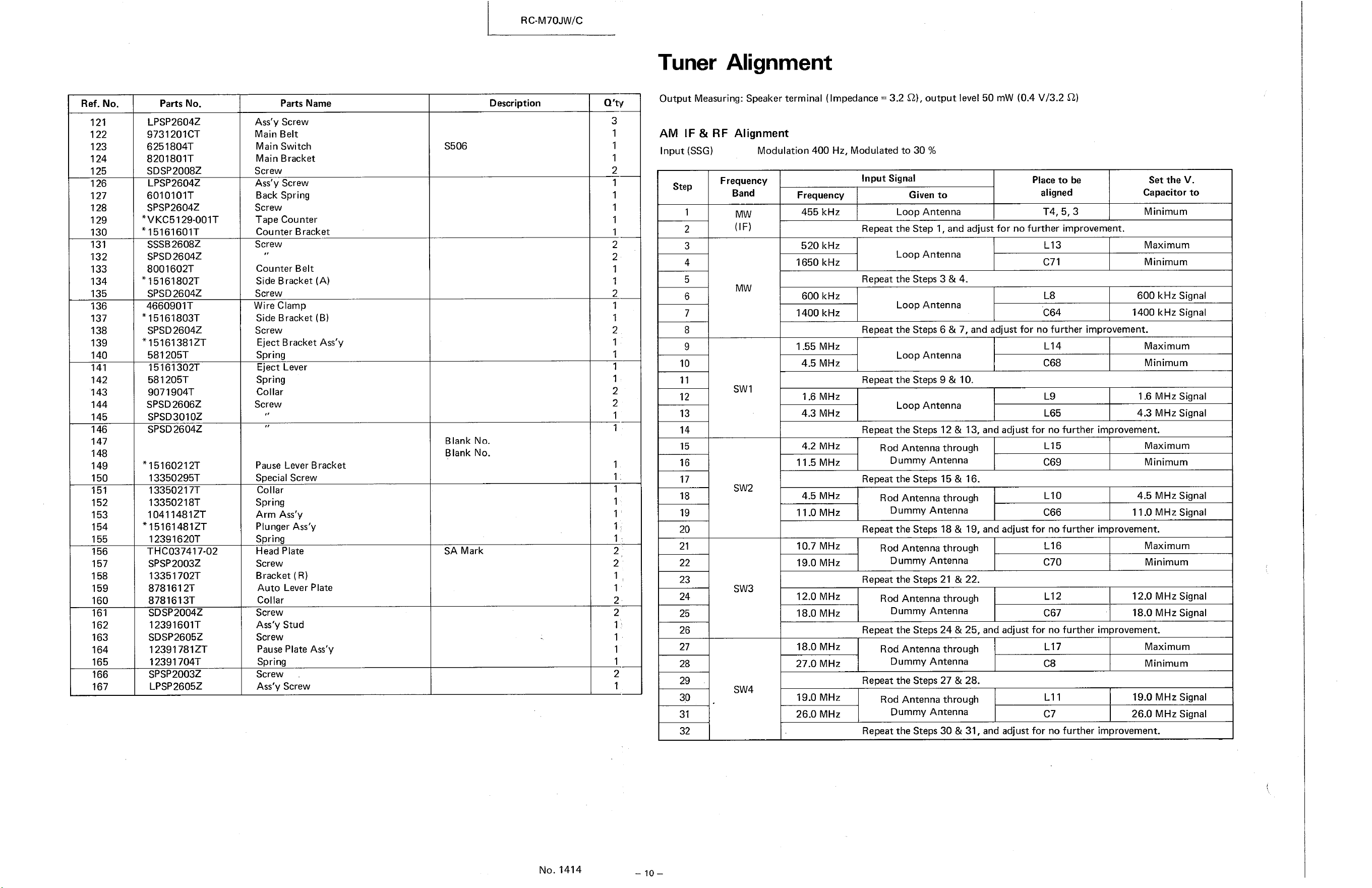
Tuner Alignment
Output Measuring: Speaker terminal (Impedance = 3.2 0), output level 50 mw (0.4 V/3.2 Q)
Ref. No.
121
122
123
Modulation 400 Hz, Modulated to 30 %
124
125
126
127
128
129
130
131
132
133
134
135
136
137
138
139
1.55 MHz
140
141
142
143
144
145
146
147
148
11.5 MHz
149
150
151
152
153
154
155
156
157
158
159
160
161
162
163
164
165
166
167
Parts No.
LPSP2604Z
973120 ICT
6251804T
8201801T
SDSP2008Z
LPSP2604Z
6010101T
SPSP2604Z
*VKC5129-001T
*15161601T
SSSB2608Z
SPSD2604Z
8001602T
*15161802T
SPSD2604Z
4660901T
*15161803T
SPSD2604Z
*15161381ZT
581205T
15161302T
581205T
9071904T
SPSD2606Z
SPSD3010Z
SPSD2604Z
*15160212T
13350295T
13350217T
13350218T
10411481ZT
*15161481ZT
12391620T
THC037417-02
SPSP2003Z
13351702T
8781612T
8781613T
SDSP2004
12391601T
SDSP2605Z
12391781 ZT
12391704T
SPSP2003Z
LPSP2605Z
Parts Name
Ass'y Screw
Main Belt
Main Switch
Main Bracket
Screw
Ass'y Screw
Back Spring
Screw
Tape Counter
Counter Bracket
Screw
Counter Belt
Side Bracket (A)
Screw
Wire Clamp
Side Bracket (B)
Screw
Eject Bracket Ass'y
Spring
Eject Lever
Spring
Collar
Screw
Pause Lever Bracket
Special Screw
Collar
Spring
Arm Ass'y
Plunger Ass'y
Spring
Head Plate
Screw
Bracket ( R)
Auto Lever Plate
Collar
Screw
Ass'y Stud
Screw
Pause Plate Ass'y
Spring
Screw
Ass'y Screw
RC-M70JW/C
Description
S506
Blank No.
Blank No.
SA Mark
No. 1414
Q'ty
3
1
2
1
1
1
2
2
1
2
1
1
2
1
1
1
2
2
1
1
1
1
1
1
2
2
1
1
2
2
1
1
1
2
1
AM IF & RF Alignment
Input (SSG)
Step
2
3
4
5
6
7
8
9
10
11
12
13
14
15
16
17
18
19
20
21
22
23
24
25
26
27
28
29
30
31
32
Frequency
Band
MW
(IF)
MW
SWI
SW2
SW3
SW4
Input Signal
Given to
Loop Antenna
Place to be
aligned
F requency
455 kHz
520 kHz
1650 kHz
600 kHz
1400 kHz
4.5 MHz
1.6 MHz
4.3 MHz
4.2 MHz
4.5 MHz
11.0 MHz
10.7 MHz
19.0 MHz
12.0 MHz
18.0 MHz
18.0 MHz
27.0 MHz
19.0 MHz
26.0 MHz
Repeat the Step I, and adjust for no further improvement.
Loop Antenna
Repeat the Steps 3 & 4.
Loop Antenna
L 13
C71
C64
Set the V.
Capacitor to
Minimum
Maximum
Minimum
600 kHz Signal
1400 kHz Signal
Repeat the Steps 6 & 7, and adjust for no further improvement.
Loop Antenna
Repeat the Steps 9 & 10.
Loop Antenna
Rod Antenna through
Dummy Antenna
Repeat the Steps 15 & 16.
Rod Antenna through
Dummy Antenna
Rod Antenna through
Dummy Antenna
Repeat the Steps 21 & 22.
Rod Antenna through
Dummy Antenna
Rod Antenna through
Dummy Antenna
Repeat the Steps 27 & 28.
Rod Antenna through
Dummy Antenna
L 14
C68
L9
L65
Maximum
Minimum
1.6 MHz Signal
4.3 MHz Signal
Repeat the Steps 12 & 13, and adjust for no further improvement.
L 15
C69
LIO
C66
Maximum
Minimum
4.5 MHz Signal
11.0 MHz Signal
Repeat the Steps 18 & 19, and adjust for no further improvement.
L 16
C70
L 12
C67
Maximum
Minimum
12.0 MHz Signal
18.0 MHz Signal
Repeat the Steps 24 & 25, and adjust for no further improvement.
L17
LII
Maximum
Minimum
19.0 MHz Signal
26.0 MHz Signal
Repeat the Steps 30 & 31 , and adjust for no further improvement.
Output (Oscilloscope)
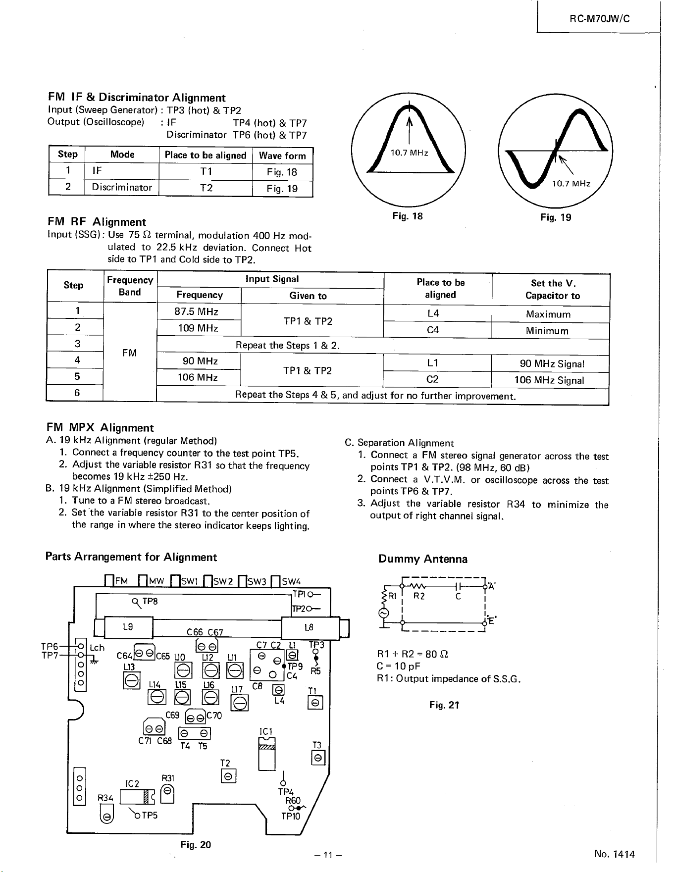
FM IF & Discriminator Alignment
Input (Sweep Generator) : T P3 (hot) & T P2
Fig. 20
TP4 (hot) & TP7
Discriminator TP6 (hot) & TP7
Place to be aligned Wave form
Step
1
2
Mode
D iscriminator
Fig. 18
Fig. 19
FM RF Alignment
Input (SSG) : Use 75 0 terminal, modulation 400 Hz mod-
ulated to 22.5 kHz deviation. Connect Hot
side to TPI and Cold side to TP2.
10.7 MHz
Fig. 18
Place to be
aligned
Step
1
2
3
4
5
6
Frequency
Band
Frequency
87.5 MHz
109 MHz
Input Signal
Given to
TPI & TP2
Repeat the Steps I & 2.
90 MHz
TPI & TP2
106 MHz
RC-M70JW/C
10.7 MHz
Fig. 19
Set the V.
Capacitor to
Maximum
Minimum
90 MHz Signal
106 MHz Signal
FM MPX Alignment
Repeat the Steps 4 & 5, and adjust for no further improvement.
C. Separation Alignment
A. 19 kHz Alignment (regular Method)
I. Connect a frequency counter to the test point TP5.
2. Adjust the variableresistor R31 sothat the frequency
becomes 19 kHz ±250 Hz.
B. 19 kHz Alignment (Simplified Method)
1. Tune to a FM stereo broadcast.
2. Set •the variable resistor R31 to the center position of
the range in where the stereo indicator keeps lighting.
1.
2.
3.
Parts Arrangement for Alignment
SW3
TP6
MW SW2
R TP8
C66 C67
Lch
c64e e C65 112 LII
o
o
o
o
o
e L14 uS L16
117 c8
C69 e éC70
C71 C68
T4
R31
SWA
TP10
3
U
R60
TPIO
—11—
Connect a FM stereo signal generator acrossthe test
points TPI & TP2. (98 MHz, 60 dB)
Connect a V.T.V.M. or oscilloscope across the test
points TP6 & TP7.
Adjust the variable resistor R34 to minimize the
output of right channel signal.
Dummy Antenna
c
RI + R2 = 80 Q
C-10pF
RI : Output impedance of S.S.G.
Fig. 21
No. 1414
Det
I Ill
Battery
check
2SC1342
2SC460
MIXER
X6 460
SW 1
CONVERTER
2SC460
sw 2
CONVERTER
X8 2SC460
CONVERTER
X9 2SC460
sw
CONVERTER
No. 1414
RC-M70JW/C
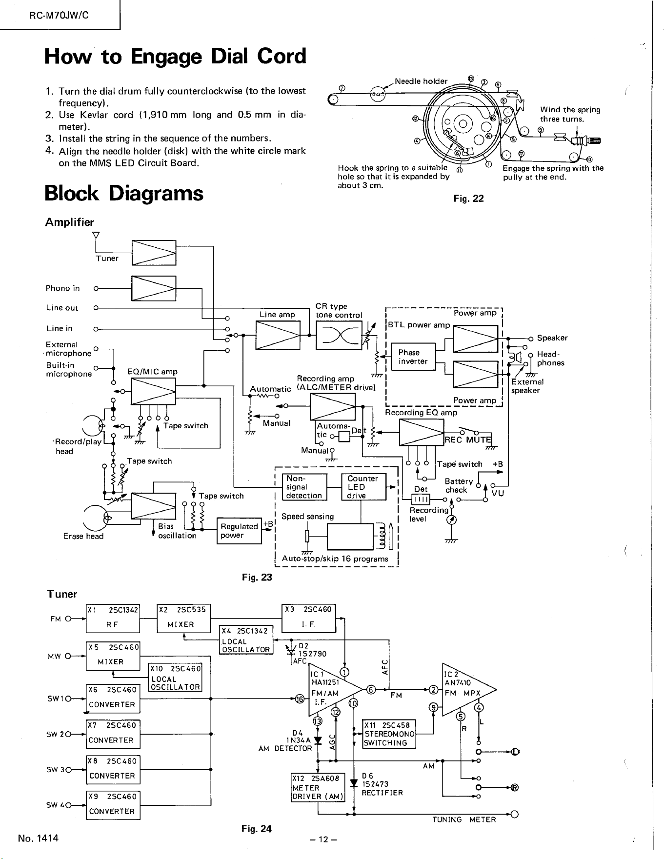
How to Engage Dial Cord
Fig. 24
1.
2.
3.
4.
Turn the dial drum fully counterclockwise (to the lowest
frequency).
Use Kevlar cord (1,910 mm long and 0.5 mm in dia-
meter).
Install the string in the sequence of the numbers.
Align the needle holder (disk) with the white circle mark
on the MMS LED Circuit Board.
Needle holder
Hook the spring to a suitable
hole so that it is expanded by
about 3 cm.
O
Fig. 22
Power amp
Poweramp_J
Wind the spring
three turns.
Engage the spring with the
pully at the end.
Block Diagrams
Amplifier
Tu ner
Phono in
Line out
Line in
E xternal
microphone
Built-in
microphone
•Record/play
head
Erase head
Tuner
Line amp
Automatic
Manual
11
1.4
Speaker
Head-
phones
EQ/MIC amp
Tape switch
.Tape switch
Tape switch
CR type
tone control
Recording amp
(A LC/METER drive)
Automa-
IBTL power amp
Phase
inverter
tic
Manual
Non-
signal
detection
Speed sensing
De t
Counter
LED
drive
Recording EQ amp
REC MUT
Tapé switch +B
VU
Bias
oscillation
xz 2SC535
MIXER
XIO 2SC460
LOCAL
OSCILLA TOR
Regulated
power
Fig. 23
xz. 2SC1342
LOCAL
OSCILLA TOR
AM
Auto-stop/skip 16 programs
2SC460
IS 2790
AFC
ICl
HA11251
6
Recording
level
IC2
ANTO
2
4
5
1 N3'.A
DETECTOR
X12 2SA608
ME TER
DRIVER (AM)
x 11 2sc458
STEREOMONO
SWITCHING
AM
1S2473
RECTIFIER
TUNING
External
speaker
.9
o
METER
RC-M70JW/C
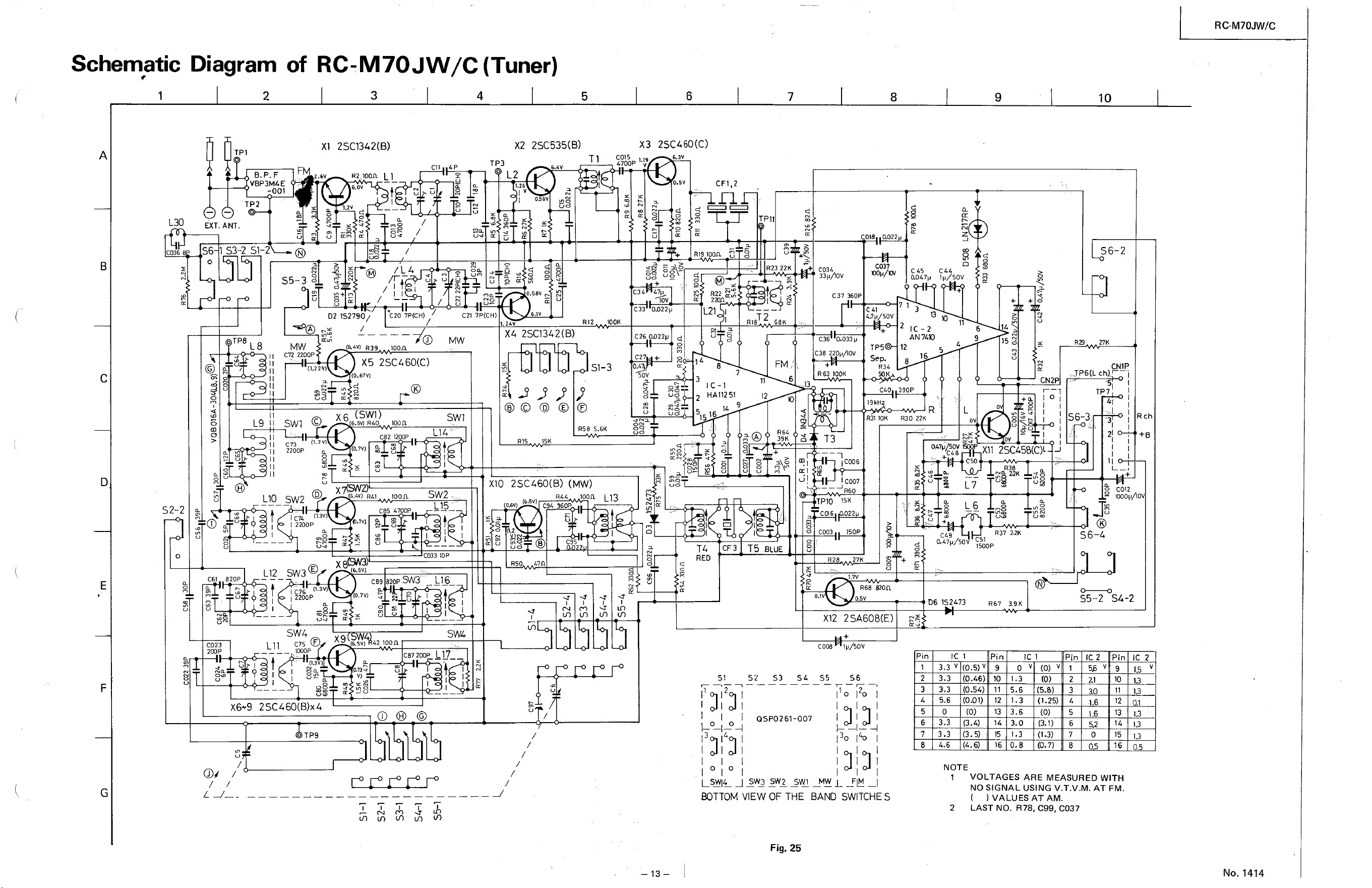
Schematic
L30
5-3
R58 5.6K
S2-2
1.3
5.6
3.6
1.3
0.8
Diagram
TPI
VBP3MZ.E
-001
TP2
EXT. ANT.
of RC-M70JW/C (Tuner)
2SC1342(B)
R2.100CLL I
02 IS2790/
C20 7P(CHY
R39 loon
X5 2SC460(C)
X3 2SC460(C)
TP3
cn 7P(CH)
1.24
MW
SWI
X2 2SC535(B)
1.26
O.S6V
6.1M
2SC1342(B)
15K
018 &022
C037
C 4S CAL
aoz.7p lp/50V
MW
C72 2200P
SWI O
C73 (1.210
2200P
SW20
I C7t.
1 2200P
SW3@
0.3V)
1 76
1 200P
SW4
cot 5
1.19
4700P
C33 0022p
100K
C26 0022P
C27 +
L13
o.sv
CFI,2
R19 toon
S6 S3-25-2 @
SS-3 g
TPII
R23 22K
C034
33p/•ov
R12
R22
RIB 68K
TP8
II
1.9 II
C37 360P
4.7 sov
C36 0.033p
C38 220p/lOV
Sep.
R63 100K
(0.67V)
X6 (SWI)
s.5V) RAO
(0.7v)
x
(6.5V)
2
5
HA11251
11
12
.13
71
12
16
390P
R30 22K
15 g
CN2
101
10
S6-2
27K
CNIP
TP6(L ch)
S6-3
21
Rch
II
LIO
L12
LII
toon
2 1200P
toon
L 14
SW2
L 15
C033 IOP
XIO 2SC460(B) (MW)
loon
0.6V)
FU.t.
(S.SV)
C9L sop
TPIO
coas
C003
R28
cao
19k
R31 10K
i coos
R60
15K
22
'SOP
27K
R68 820Q
2SA608(E)
047p/* XII —J
C50
R38
N 2.2K
R37 22K
820P
C89820PSN3
(0,7v)
0.47p/50
06 1S2L73
1500P
R67
C012
2 mop/l
S 6—4
SS-2
C023
200P
0.75(D (6,sv)Q
C008
C87 200P
L16
SW4
LL7_
V)
O
REO
o
39K
T5 BLUE
QSP0261-007
o
lp/SOV
110 120
130 140
Pin
2
6
8
3.3 V
3.3
3.3
5.6
3.3
3.3
4.6
(0.5) V
(0.46)
(0.54)
(0.01)
(0)
(3.4)
(3.5)
(4.6)
Pin
9
10
11
12
13
14
15
16
19K
1.3
3.0
(0)
(5.8)
(1.25)
(0)
(3.1)
(1.3)
(0.7)
Pin
3
6
7
1.6
Pin
9
10
11
12
13
15
I-SYL -J _MY L —FIM—
BOTTOM VIEW OF THE BAND SWITCHES
Fig. 25
NOTE
1
2
VOLTAGES ARE MEASURED WITH
NO SIGNAL USING V.T.V.M. AT FM.
( ) VALUES AT AM.
LAST NO. R78, C99, C037
1.3
1.3
1.3
1.3
No. 1414
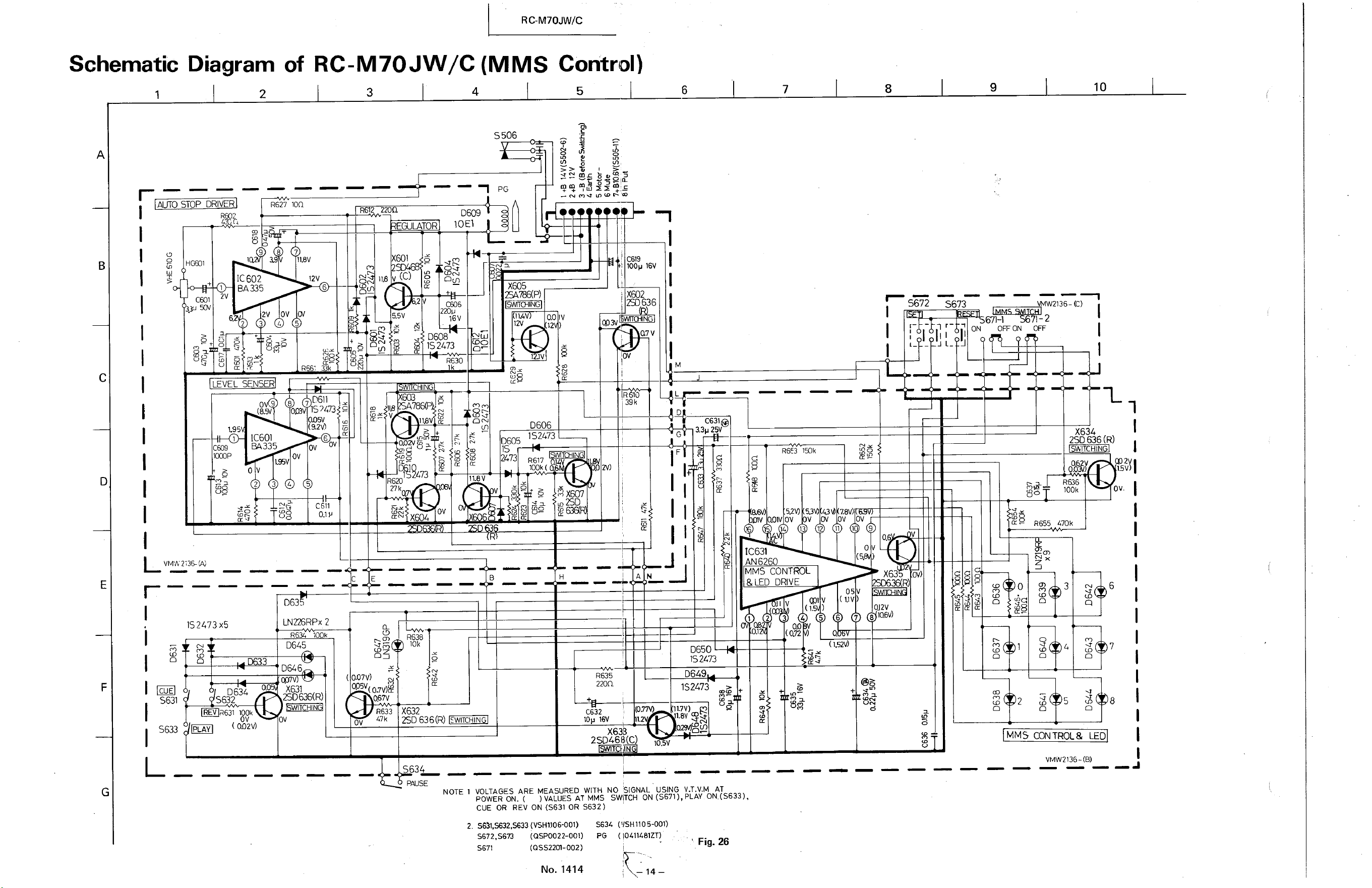
RC-M70JW/C
of RC-M70JW/C (MMS Control)
Schematic
R655 470k
Diagram
10
AUTO STOP DR
VMW
R627 100
IC602
BA335
2V ov
VEL SENS
0609
LAT R IOEI
220p
IS 2473
R€30
'tev
ov
S506
X605
EA786(P)
swno-ll
tzv
11.8V
12V
omv 32473
( A2V)
C 11
0.1 P
601
27k
v
16V
,X602
636
39k
S672
00
S673
00
12
1.95
(891
IC601
BA335
0606
1S2473
0605
IS
R617
C63i@
33B 25V
N
0650
IS 2473
D649
1S2473
.7T0 n7V) g
1.8V
29$8(f)
R6f3 ISOk
Q3'0
671-1
OFF ON
2
1-2
80
136- C)
X634
2SD 636 (R)
R&36
100k
A
IC631
AN6
MMS CONTROL
LED DRIVE
(1
(QT2
7.8V)
11
05
7
( 1.520
X63
Q12V
3
CUE
IS2473x5
D 634
063.
LNZ26RPx 2
D64S
D646
X631
2SD636(R)
( 0.07V)
R633
47k
R638
10k
X632
R635
220Q
C632
top 16V
6
7
8
S633 (omv)
2SD46B(C)
105.'
MMS CONTROL & LED
VMM136-(B)
S634
NOTE 1 VOLTAGESARE MEASUREDWITH NO SIGNAL USING V.T.V.M AT
POWERON.( )VALUESATMMS SWITCHON(S671),PLAYON(S633),
CUE OR REV ON ($31 OR S632)
2. S631,S632.S633(VSHü06-001) S634 ("SH1105-001)
s672.s673 (090022-001) PG (
Fig. 26
S671
(QSS2201-002)
No. 1414
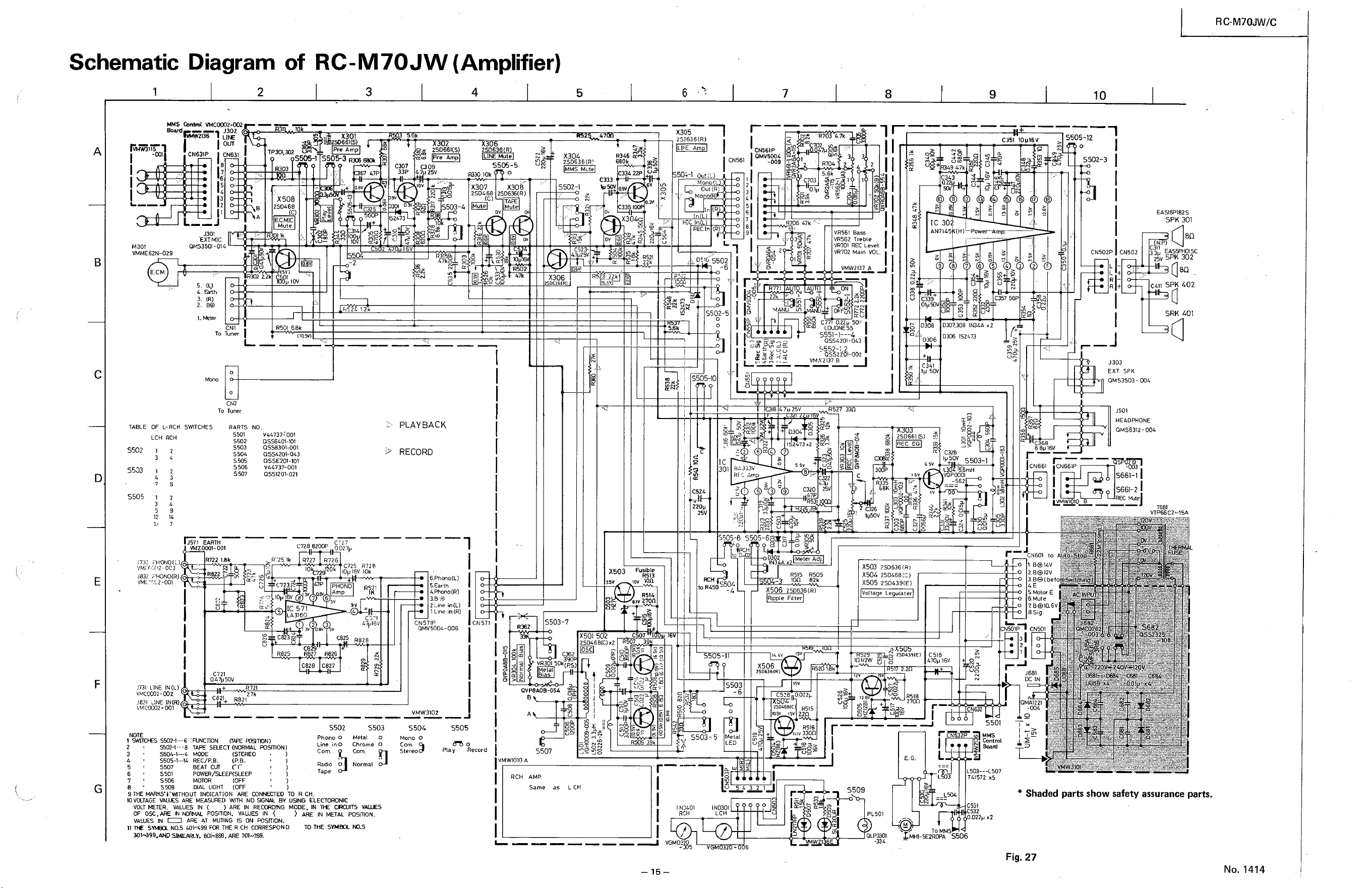
Schematic
Diagram
2
WS WC0002-002
of RC-M70JW (Amplifier)
1
M30t
VMtÆ62N-029
E.CM
TABLE OF I-RCH
LCH RCH
3
4
2S0661(S)
e Amp
5
X304
2SD636(Ri
MS
6
X305
2S0636(R)
Am
504-1
Cut
REC:n
OE SS02
7
R706 47k
8 9
10
X30
pre Amp
ssos-l S505-3
4
C351
CN631P ct•4631
8
7
6
3
130!
EXT. MIC.
aus3501-01 t.
s.
3.
2.
x
26 R
S50S-5
R346
680k
01561
R303
x 508
2S0L68
ECMIC
Mute
RSOI 68k
C307 009
33P 25'.'
S2Z.73
CN56iP
0MV5004
-009
R771
Q7k
5.6k
2
1.7k
B
R332 22k
5503-4
C333
S502-1
sov
c
5
6
7
9
1.3
IC 302
C339
0
S502-3
CNSOZP CNS02
EAS16P182S
SPK 301
311
EAS5Pt01SC
SPK 302
SPK 402
SRK 401
c
G
3
4
1
3
5
12
3
g
2
9
7
-2
0027p
R727 R7?6
C723 R728
10k
6
A TO
4. üth
To
VRS61 Bass
VR562 Treble
VRTOI REC Levet
VR702 VOu.
VMW2137 A
LCXJONÆS
S551-l---4
assu.201-043
VMA'2137 B
RS27 330
7
CNI
finer
CN2
S502
S503
S505
0308 030Z308 x z
0306
C31.l
2S0661 S)
lp 50M
SS03-l
01
-562
.:731
vw.t<B2-0C2
2731
-002
IN(R)
SWITCHES RANTS
sso'
S502
ss03
ssoz.
S506
s 507
EARTH
047psov
NO.
QSS8301-001
QSS4201-043
OSSE201-K)1
•.144737-001
OSS1201-021
R?2S 1k
C723æ
c 571
LA3t€O
can
C82B
R 721
27k
C821 R821
1 SWITCt-ES $02-1„.6 -'FUNCTION
3
C82S
6
C827
S502
Phono 0
Line ino
Com.
Radio O
Tape
R828
S503
Metal 0
Chrome o
PLAYBACK
RECORD
5Earth
in(L)
Lene in(R)
CN571p
VMW3102
503010k O
X307 X30g
2S0468 2SD636(R)
Mut
2
47k
CN571
X306
S503-7
962
VR30isoqps
S502-s
0
S505-10
30 i
CS24
220p
xs03
zsv
22p
Fusible
R513
Ion
g 7u2SV
IS2473
Amp
R33
68K
SS05-8 S505-6
068
CN661 CN66iP
L 10
CN601 to
1 B@IAV .
O
'P
J 303
EXT SPK
OMS3503 - 004
J501
HEADPHONE
QMS6312-004
S661-1
S661-2
REC
VTP66C2-15A
,assh29:• .
X501 502
2SD'68C)
RS07
R514
39
X506
ppl e
X506
ZS0636(R)
2
RS
R5iS R505
'OQ 82k
29636 (R)
Fiter
RSIS
R516
3300
X503 2S0636(R)
X504
X505 2S0439{E)
Voltage tegulater
ZSO'35(E)
uzw
5509
6 Mute
CN301
J 691
OC IN
S504
Mono O
Stereo
S505
may Record
QVP8AOB-054
S507
to RCSO
S503-5
-4
S503
o
. etal
2
3
5
6
7
8
LEO u
dil
C518
TO MMS
S501
MMS
Control
LS03---L507
TLIS72
C532
.ozzvxz
. AC•.IN
•vkWBIOÜ
SS05-1---14
S507
SSOI
sso€
s 509
TAPE SELECT
MCOE
(STEREO
REC/P.B. (P.B.
BEAT CUT C'f'
(OFF
DIAL (OFF
RCH AMP.
Same
as
s THE MARKSVWITHOUT INDICATION ARE TO R CH.
10 VCLTAGE VAUES ARE MEASURED WITH NO BY USING ELECTORONC
) IN RECUONG MOOE. IN VALLES
VALUES IN (
OF osc.øæ POSITION.VALLES IN < ) IN METAL POSmON.
VAUES ARE AT MUTING IS ON POSITION.
11 "-E NO.s 401—499FOR TYE R CH CCRRESPOND TO THE
N)1-a99.EiD 701—799.
RCH
IND301
LCH
-J
6
PLSOI
-334
%-5E2RtPA S506
* Shaded parts show safety assurance parts.
Fig. 27
RC-M70JW/C
No. 1414
RC-M70JW/C
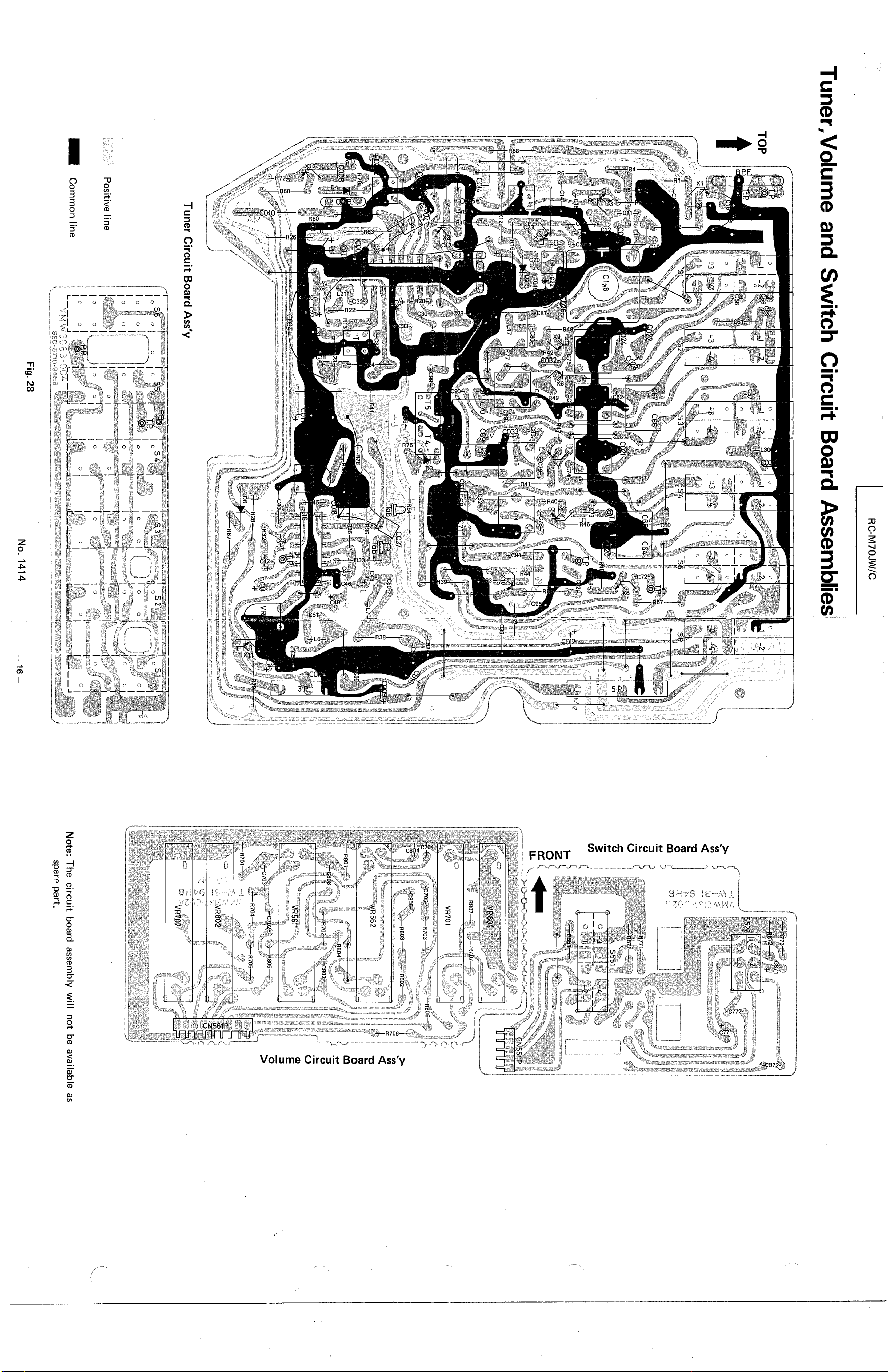
Tuner,VoIume and Switch Circuit Board Assemblies
TOP
{ c178
-8
Cl
T6b
Tuner Circuit Board Ass'y
Positive line
Common line
Fig. 28
No. 1414
SS?i
807
VR701
R803
R562
R701
_.VRSdi
5TP
Note: The circuit board assembly Will not be available as
sparo part.
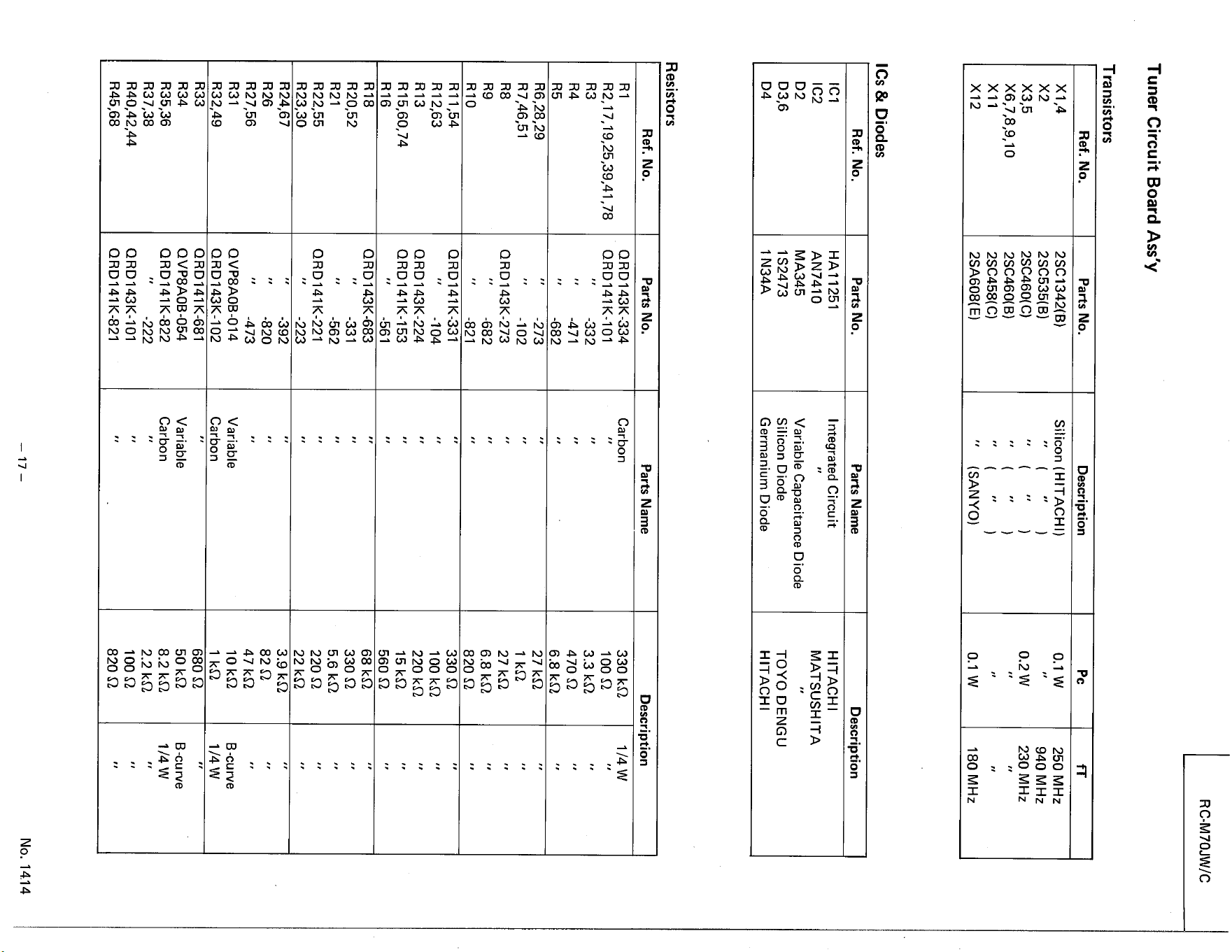
Tuner Circuit Board Ass'y
Transistors
Ref. No
Xl,4
X3,5
X6 789 10
XII
X12
& Diodes
Ref. No.
ICl
IC2
D2
D3,6
Resistors
Ref. No.
RI
R5
RIO
RI 1,54
RI 2,63
R13
R16
R18
R20,52
R21
R22,55
R23,30
R24,67
R26
R27,56
R31
R32,49
R33
R34
R35,36
R37,38
R45,68
Parts No.
2SC1342(B)
2SC535(B)
2SC460(C)
2SC460( B)
2SC458( C)
2SA608( E)
Parts No.
HAI 1251
AN7410
MA345
1 S2473
1 N34A
Parts No.
QRD143K-334
QRD141K-101
-332
-471
-682
-273
-102
QRD143K-273
-682
-821
ORD141K-331
-104
ORD 1431<-224
ORD141K-153
-561
Q RD 1431<-683
-331
-562
QRD141K-221
-223
-392
-820
-473
OVP8AOB-014
QRD143K-102
QRD141K-681
QVP8AOB-054
QRD141K-822
-222
QRD143K-101
ORD141K-821
Description
Silicon (HITACHI)
(SANYO)
Parts Name
Integrated Circuit
Variable Capacitance Diode
Silicon Diode
Germanium Diode
Parts Name
Carbon
Variable
Carbon
Variable
Carbon
pc
0.1 w
0.2 w
0.1 w
RC-M70JW/C
250 MHz
940 MHz
230 MHz
180 MHz
Description
HITACHI
MATSUSHITA
TOYO DENGU
HITACHI
Description
330 kO
100 Q
3.3 kO
470 Q
6.8
27 k0
27 kQ
6.8
820 Q
330 0
100 kQ
220
15 kO
560 0
68 kO
330 0
5.6 kO
220 0
22
3.9 kQ
82 Q
47 kQ
10 kQ
680 0
50 kQ
8.2
2.2 kQ
100 0
820 0
1/4 w
B-curve
1/4 w
B -cu rve
1/4 w
No. 1414
RC-M70JW/C
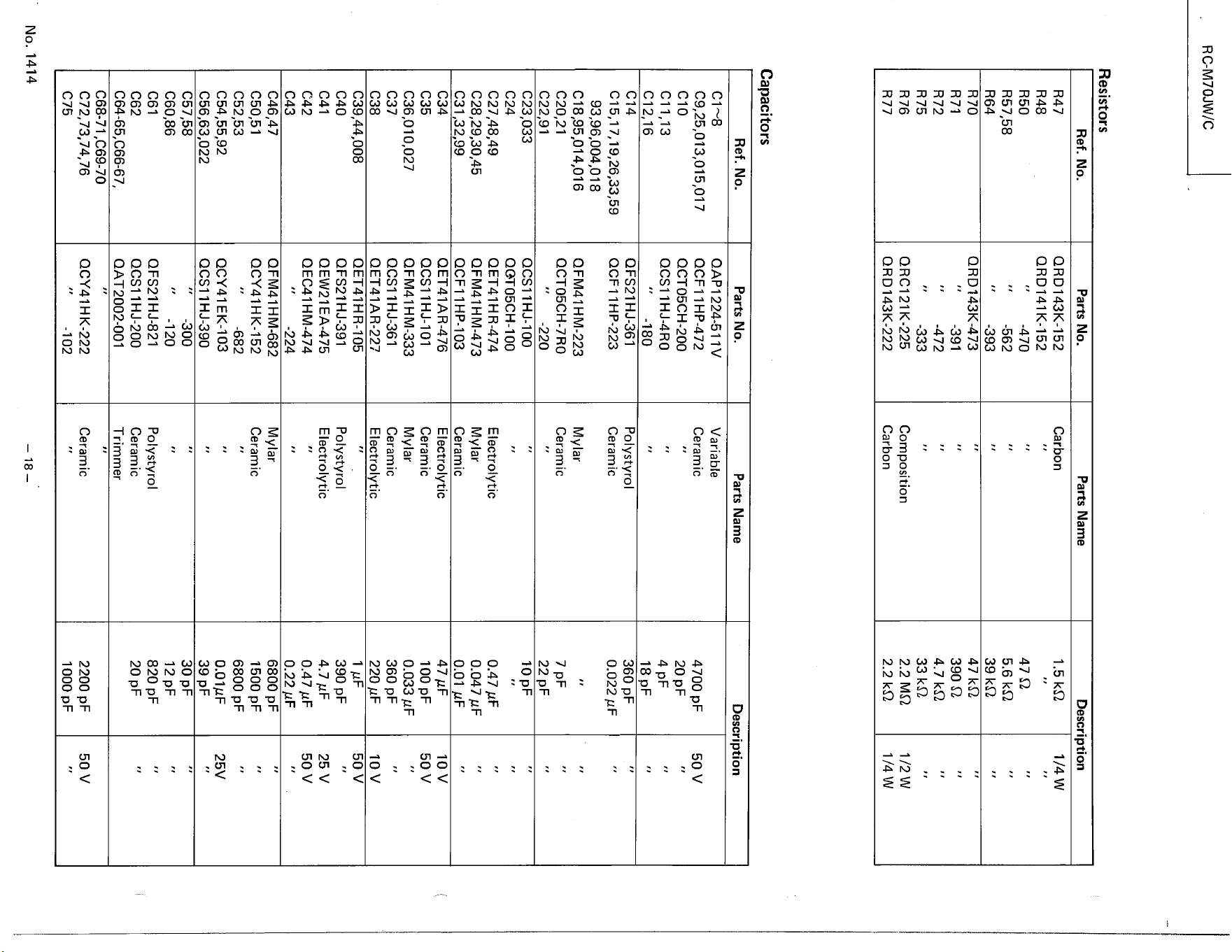
Resistors
Ref. No
R47
R48
R50
857,58
R64
R70
R71
R72
R75
R 76
R77
Capacitors
Ref. No.
CIO
Cll,13
C12,16
C14
C20,21
C22,91
C23,033
C24
C31
C34
C35
C37
C38
C40
C41
C42
C43
C46,47
C50,51
C52,53
C57,58
C60,86
C61
C62
C64-65,C66-67,
C68-71 ,C69-70
C75
No. 1414
Parts No.
ORD143K-152
QRD141K-152
-470
-562
-393
QRD143K-473
-391
-472
-333
ORC121 K-225
QRD143K-222
Parts No.
QAPI 224-511 V
QCF11HP472
QCT05CH-200
QCSI 1HJ-4RO
-180
QFS21HJ-361
QCFI 1 HP-223
OFM41HM-223
QCT05CH-7RO
-220
QCSI 1 HJ-IOO
Q@T05CH-100
OET41HR-474
OFM41HM-473
OCF11HP-103
OET41AR-476
IHJ-IOI
OFM41HM-333
QCSI 1 HJ-361
OET41AR.227
OET41HR-105
QFS21HJ-391
QEW21EA-475
OEC41HM-474
-224
QFM41HM-682
QCY41HK-152
-682
OCY41EK-103
QCSI 1HJ-390
-300
-120
OFS21HJ-821
QCSI 1HJ-200
QAT2002-001
QCY41HK-222
-102
Parts Name
Carbon
Composition
Carbon
Parts Name
Variable
Ceramic
Polystyrol
Ceramic
Mylar
Ceramic
Electrol ytic
Mylar
Ceramic
Electrolytic
Ceramic
Mylar
Ceram ic
Electrolytic
Polystyrol
Electrolytic
Mylar
Ceramic
Polystyrol
Ceramic
Trimmer
Ceramic
Description
1.5 kO
47 0
5.6
39
47 kQ
390 0
4.7 kQ
33 kO
2.2 MQ
2.2 kO
1/4 w
1/4 w
Description
4700 pF
20 pF
18 pF
360 pF
0.022
22 pF
10 pF
0.47 uF
0.047
0.01
47 IIF
100 pF
0.033
360 pF
220
1 1.LF
390 pF
4.7 'IF
0.47
0.22
6800 pF
1500 pF
6800 pF
O.01gF
39 pF
30 pF
12pF
820 pF
20 pF
2200 pF
1 OOO
50 v
10 v
50 v
10 v
50 v
25 v
50 v
25V
50 v
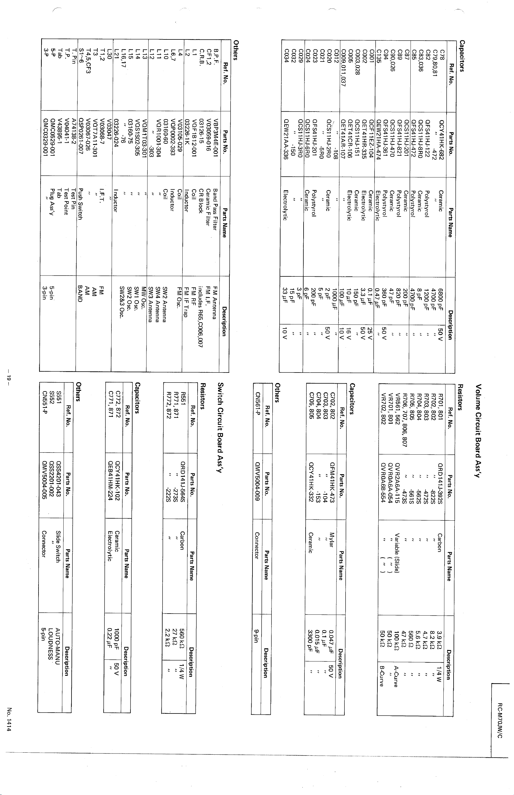
Volume Circuit Board Ass'y
Capacitors
Ref. No.
C78
C82
C83,036
C85
C87
C89
C90,026
C94
C135
COOI
c002
C003,028
C005
c009,011 ,037
C012
C020
C021
C023
C024
C029
C032
C034
Others
Ref. No
B.P.F.
CFI,2
C.R.B.
L2
L4
L6,7
LIO
LII
L 12
L 13
L 14
L 15
L 16,17
L21
L30
T3
T. Pin
Tab
3-p
Parts No.
QCY41HK-682
-472
OFS41HJ-122
QCSI 1
QFS41 HJ-472
QCSI 1HJ-201
QFS41HJ-821
QCSI 1HJ470
OFS41HJ-361
QEW21 HA-474
OCF11EZ-104
QET41HR-335
QCS11HJ-151
OET41CR-106
QET41AR-107
-108
QCSI IHJ-2RO
-5RO
QFS41HJ-201
QCSI IHJ-6RO
OCSI 1HJ-3RO
-150
OEW21AA-336
Parts No.
VBP3M4E-001
V03059-016
03126-15
VQFIB12-001
03226-1K
V03105-029
VQP0002-393
03160-60
VQR1001-304
-303
VOMIT03-301
VOS IS02-305
03160-75
-76
03226-024
V03047
V03068-7
VQT7A11-301
V03067-026
QSP0261-007
A 74138-2
V04041-1
V43895-1
QMC0529-001
OMC0329-001
Parts Name
Ceramic
Polystyrol
Ceramic
pol rol
Ceramic
Polystyrol
Ceramic
Polystyrol
Electrol tic
Ceramic
Electrolytic
Ceramic
Electrolytic
Ceram ic
Polystyrol
Ceram ic
Electrolytic
Parts Name
Band Pass Filter
Ceramic F ilter
CR Block
coil
I nductor
Coil
I nductor
Coil
I nductor
I.F.T.
Push Switch
Test Pin
Test Point
Tab
Ptug Ass'y
6800 pF
4700 pF
1200 pF
8 pF
4700 F
200 pF
820 pF
47 pF
360 pF
0.47 F
0.1 gF
3.3 gr-
150 pF
10gF
100 F
1000
200 pF
15 pF
33 gF
Description
50 v
50 v
25 v
50 v
16 v
10 v
50 v
10 v
Resistors
Ref. No.
8701, 801
R702, 802
R703, 803
R704, 804
R705, 805
R706, 707, 806, 807
VR561 , 562
VR701, 801
VR702, 802
Capacitors
Ref. No.
C702, 802
C703, 803
C704, 804
C705, 805
Others
Ref. No
CN561 -p
Parts No.
QRD141J-392S
-822S
-472S
-562S
-561S
.473 s
QVR2A6A-115
QVROA6A-054
QVROA6B-554
Parts No.
QFM41HK473
-104
-153
QCY41 H K-332
Parts No.
QM V5004-009
Parts Name
Carbon
Variable (Slide)
Parts Name
Mylar
Ceramic
Parts Name
Connector
Parts Name
Carbon
Parts Name
Ceramic
Electrolytic
Parts Name
Slide Switch
Connector
3.9 kO
8.2
4.7 kQ
5.6 kO
560 Q
47
100
50 kO
50
RC-M70JW/C
Description
1/4 w
A-Curve
B-Curve
Description
FM Antenna
FM I.F.
includes
FM IF Trap
FM Osc.
SW2 Antenna
SW4 Antenna
SW3 Antenna
MW osc.
SWI osc.
SW2 osc.
SW2&3 osc.
AM
AM
BAND
5-pin
3-pin
Switch Circuit Board Ass'y
Resistors
Ref. No.
R551
R771, 871
R772, 872
Capacitors
Ref. No.
C772, 872
C771, 871
Others
Ref. No
S551
S552
CN551-P
Parts No.
QRD141J-564S
-273S
-222S
Parts No.
QCY41HK-102
QEB41 HM-224
Parts No.
QSS4201-043
QSS2201-002
QMV5004-005
Description
0.047 gF
50 v
0.1
0.015
3300 pF
Description
9-pin
Description
560kQ 1/4 W
27
2.2 kO
Description
1000 pF
50 v
0.22
Description
AUTO-MANU
LOUDNESS
5-pin
No. 1414
RC-M70JW/C
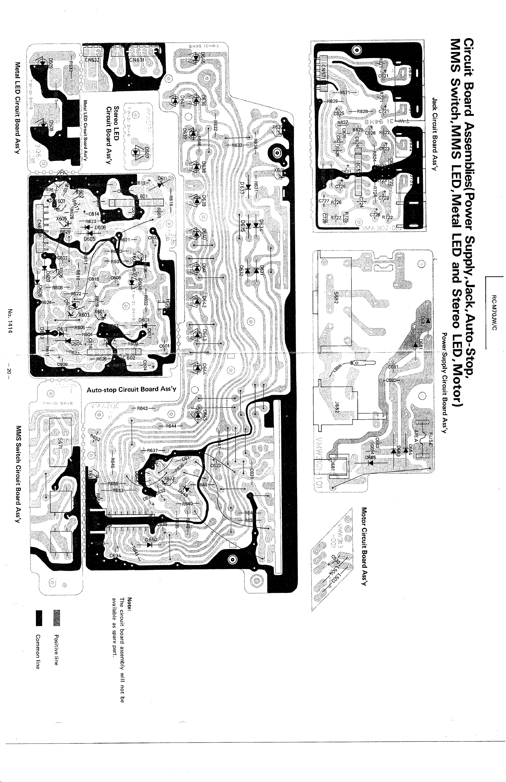
Circuit Board Assemblies( Power Supply,Jack,Auto-Stop,
MMS Switch,MMS LED,Metal LED and Stereo LED, Motor)
Power Supply Circuit Board Ass'y
Jack Circuit Board Ass'y
bG84
D6åg
R72h o
F„8-Æ+R824
CNS9!
R724—;
724!
633
.639
16
LR725
728
Motor Circuit Board Ass'y
-oct
-S682
602
e---n€lå:—
0609.
J68i
6ÅT'
663%
D5QT
3CF-e
Stereo LED
Circuit Board Ass'y
Metal LED Circuit Board Ass'y
0508
Metal LED Circuit Board Ass'y
8461
CN6
D64t.
961??
6
t604
h61f1
-D 39
No. 1414
681
R645——
-7"'71
Note:
The circuit board assembly will not be
available as spare part.
Positive line
Common line
MMS Switch Circuit Board Ass'y
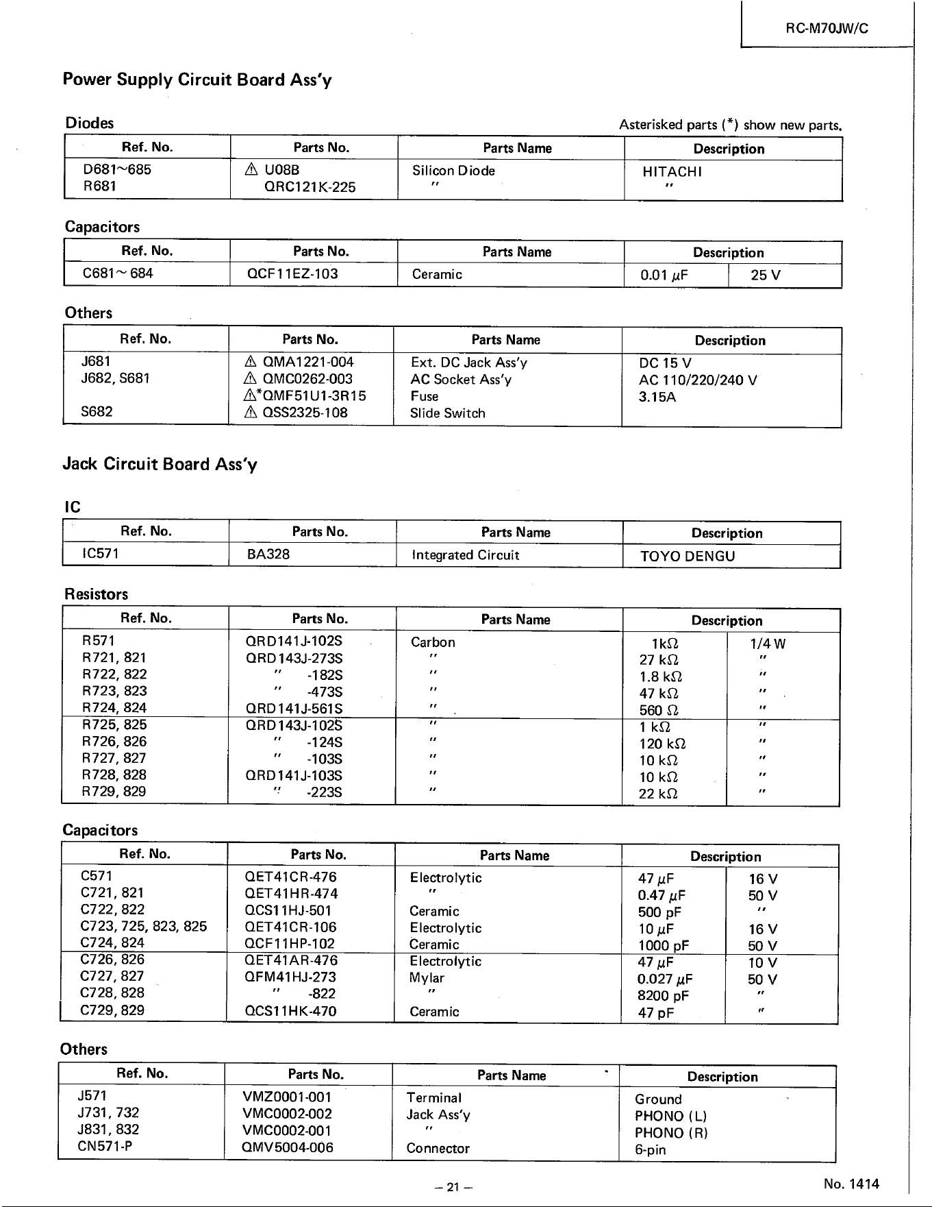
Power Supply Circuit Board Ass'y
Diodes
Ref. No.
R681
Capacitors
Ref. No.
C681 684
Others
Ref. No.
J681
J682, S681
S682
Parts No.
A U08B
ORC121K-225
Parts No.
QCF11EZ-103
Parts No.
A QMA1221-004
A QMC0262-003
A*OMF51U1-3R15
A oss2325-108
Parts Name
Silicon Diode
Parts Name
Ceramic
Parts Name
Ext. DC Jack Ass'y
AC Socket Ass'y
Fuse
Slide Switch
Parts Name
Integrated Circuit
Parts Name
Carbon
Parts Name
Electrolytic
Ceramic
Electrolytic
Ceramic
Electrolytic
Mylar
Ceramic
Parts Name
Terminal
Jack Ass'y
Connector
— 21 —
RC-M70JW/C
Asterisked parts (*) show new parts.
Description
HITACHI
Description
0.01 25 v
Jack Circuit Board Ass'y
Ref. No.
IC571
Resistors
Ref. No.
R571
R721, 821
R722, 822
R723, 823
R724, 824
R725, 825
R726, 826
R727, 827
R728, 828
R729, 829
Capacitors
Ref. No.
C571
C721, 821
C722, 822
C723, 725, 823, 825
C724, 824
C726, 826
C727, 827
C728, 828
C729, 829
Others
Ref. No.
J571
J731, 732
J831, 832
CN571-P
Parts No.
BA328
Parts No.
ORD141J-102S
ORD 143J-273S
-182S
-473S
ORD 141 J-561S
QRD143J-102S
-124S
-103S
QRD141J-103S
-223S
Parts No.
QET41CR-476
OET41HR-474
QCSI IHJ-501
QET41CR-106
QCF11HP-102
QET41AR476
QFM41 HJ-273
-822
QCSI 1HK-470
Parts No.
VMZOOOIOOI
VMC0002002
VMC0002-001
QMV5004-006
Description
DC 15 v
AC 110/220/240 V
3.15A
Description
TOYO DENGU
Description
1/4 w
27
1.8
47 kQ
560 0
120 kO
10
10
22 kO
Description
47 gF
0.47 gF
500 pF
10
1000 pF
47 BF
0.027 gF
8200 pF
47 pF
16 v
50 v
16 v
50 v
10 v
50 v
Description
Ground
PHONO (L)
PHONO (R)
6-pin
No. 1414
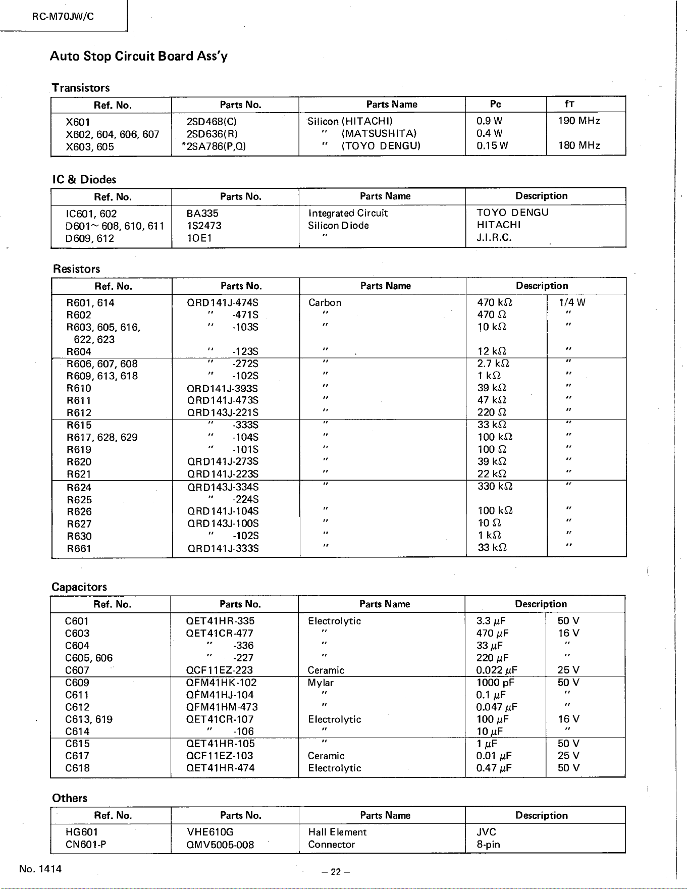
Transistors
Ref. No.
X601
X602, 604, 606, 607
605
& Diodes
Ref. No.
IC601, 602
D601& 608, 610, 611
D609, 612
Resistors
Ref. No.
R601, 614
R602
R603, 605, 616
R 604
R606, 607, 608
R609, 613, 618
R610
R611
R612
R615
R617, 628, 629
R619
R620
R621
R624
R625
R626
R627
R630
R661
Capacitors
Ref. No
C601
C603
C604
C605, 606
C607
C609
C611
C612
C613, 619
C614
C615
C617
C618
Others
Ref. No.
HG601
CN601-P
No. 1414
RC-M70JW/C
Auto Stop Circuit Board Ass'y
622, 623
Parts No.
2SD468(C)
2SD636( R)
Parts No.
BA335
1S2473
IOEI
Parts No.
QRD141J-474S
-471S
-103S
-123S
-272S
-102S
ORD141J-393S
QRD141J473S
QRD143J-221S
-333S
-104S
-101S
QRD141J-273S
ORD 141J-223S
QRD143J-334S
-224S
QRD141J-104S
QRD143J-100S
-102S
QRD141J-333S
Parts No.
QET41HR-335
QET41CR-477
-336
-227
QCFII EZ-223
QFM41HK-102
OFM41HJ-104
QFM41HM473
QET41CR-107
QET41HR-105
QCF11EZ-103
QET41HR-474
Parts Name
Silicon (HITACHI)
(MATSUSHITA)
(TOYO DENGU)
Parts Name
Integrated Circuit
Silicon Diode
Parts Name
Carbon
Parts Name
Electrolytic
Ceramic
Mylar
Electrolytic
Ceramic
Electrolytic
Parts Name
Hall Element
Connector
— 22 —
pc
0.9 w
0.4 w
0.15W
190 MHz
180 MHz
Description
TOYO DENGU
HITACHI
J.I.R.C.
Description
470
470 Q
101<0
12
2.7 kO
39 kQ
47
220 Q
33
100
100 Q
39
22
330 kO
100 kO
10 Q
33
3.3
470
33 gr-
220 gF
0.022
1000 pF
0.1 gr-
0.047
100
10 AF
0.01
0.47
1/4 w
Description
50 v
16 v
25 v
50 v
16 v
50 v
25 v
50 v
-106
Parts No.
VHE610G
QMV5005008
Description
JVC
8-pin
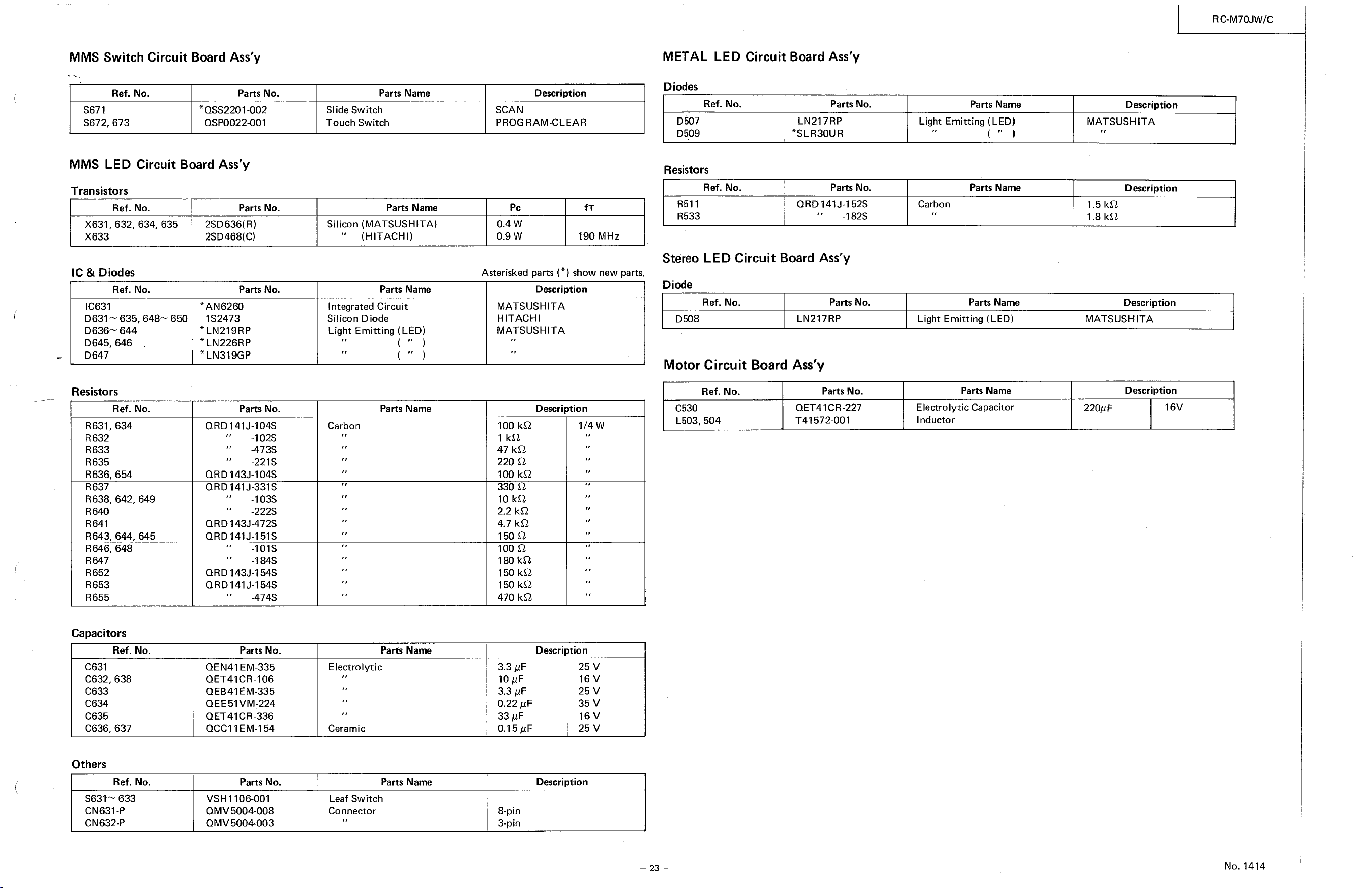
MMS Switch Circuit Board Ass'y METAL LED Circuit Board Ass'y
Ref. No.
S671
S672, 673
Ref. No
Ref. No
L503, 504
S631& 633
Parts No.
*oss2201-002
QSP0022-001
Parts Name
SI ide Switch
Touch Switch
Parts Name
Silicon (MATSUSHITA)
(HITACHI)
Parts Name
Integrated Circuit
Silicon Diode
Light Emitting (LED)
Parts Name
Carbon
Parts Name
Electrolytic
Ceramic
Parts Name
Leaf Switch
Connector
Description
SCAN
PROGRAM-CLEAR
MMS LED Circuit Board Ass'y
pc
0.4 w
0.9 w
fT
190 MHz
Diodes
D507
D509
Resistors
R511
R533
Parts No.
LN217RP
*SLR30UR
Parts No.
QRD141J-152S
-182S
Transistors
Ref. No.
X631 , 632, 634, 635
X633
IC & Diodes
Ref. No.
IC631
D631 635, 648æ 650
D636 644
D645, 646
D647
Resistors
Ref. No.
R631, 634
R632
R633
R635
R636, 654
R637
R638, 642, 649
R640
R641
R643, 644, 645
R646, 648
R647
R652
R653
R655
Capacitors
Ref. No
C631
C632, 638
C633
C634
C635
C636, 637
Others
Ref. No
CN631-P
CN632-P
Parts No.
2SD636( R)
2SD468(C)
Parts No.
*AN6260
1S2473
*LN219RP
*LN226RP
*LN319GP
Parts No.
QRD141J-104S
-102S
-473S
-221 s
ORD143J-104S
QRD141J-331S
-103S
-222S
ORD 143J-472S
QRD141J-151S
-101S
-184S
ORD 143J-154S
QRD141J-154S
-474S
Parts No.
QEN41 EM-335
QET41CR-106
QEB41EM-335
QEE51 VM-224
QET41CR-336
OCC11EM-154
Parts No.
VSHI 106-001
QMV5004-008
QMV5004-003
Stereo LED Circuit Board Ass'y
Asterisked parts (* ) show new parts.
Description
MATSUSHITA
HITACHI
MATSUSHITA
Description
Diode
Ref. No.
D508
Parts No.
LN217RP
Motor Circuit Board Ass'y
Ref. No.
Parts Name
Light Emitting (LED)
Parts Name
Carbon
Parts Name
Light Emitting (LED)
Parts Name
Electrolytic Capacitor
Inductor
RC-M70JW/C
Description
MATSUSHITA
Description
1.5
1.8
Description
MATSUSHITA
Description
C530
Parts No.
QET41CR-227
T41572-001
220gF
100 kQ
47 kO
220 0
100 kQ
330 0
10
2.2 kQ
4.7
1500
100 Q
180 kO
150 kO
150 kO
470 kQ
3.3 gF
10 gr-
3.3
0.22 gF
33
0.15gF
1/4 w
Description
25 v
16 v
25 v
35 v
16 v
25 v
Description
8-pin
3-pin
16V
No. 1414
RC-M70JW/C
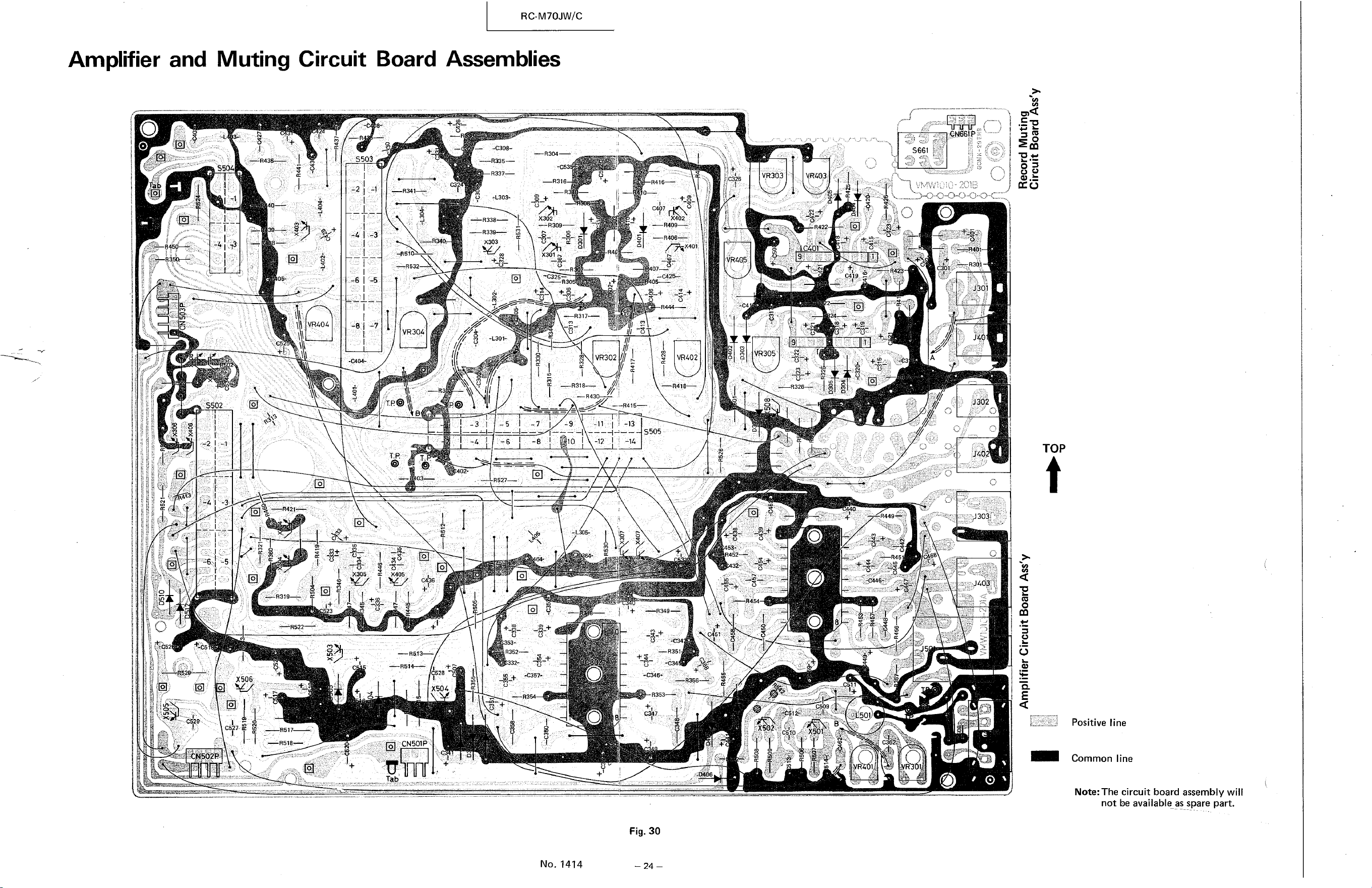
Assemblies
Amplifier and Muting Circuit
S503
SS04
.C404-
S502
23
xsoe
Board
—R51
VR30Z.
R337—
——R338—
—R339—
-L301-
R 304
- ,- .—R31
-C325—
VR402
VR303
VR305
4-+
R4?2 (
_C511
CN66!pg:
S661
-JåQi
u 302
VR302
.•—8430—
-12 1
O
No, 1414
-13
— S505
-14
Fig. 30
TOP
R527—-
R352—
453,
' : —R513—
X504
'CN501P
Tab
Positive line
Common line
Note: The circuit board assembly will
not be available as spare part.
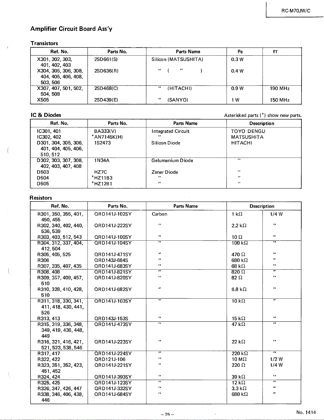
Amplifier Circuit Board Ass'y
Transistors
Ref. No.
401,
404,
X505
X301, 302, 303
402, 403
305, 306, 308
503, 506
407, 501, 502
504, 508
405, 406
510, 512
402, 403, 407, 408
450, 455
402, 440
536, 539
412, 504
407 , 435
409, 457
410, 428
430, 441
436, 448
416, 421
R316, 321,
521, 523, 538, 546
451,452
426, 447
405, 406, 408
Parts No.
2SD661 (S)
2SD636(R)
2SD468(C)
2SD439(E)
Parts No.
BA333(V)
1S2473
IN34A
HZ7C
*HZ11B3
*HZ12B1
Parts No.
QRD141J-102SY
QRD141J-222SY
QRD141J-100SY
QRD141J-104SY
QRD141J-471SY
QRD143J-684S
QRD141J-683SY
ORD141J-821SY
QRD141J-820SY
QRD141J-682SY
QRD141J-103SY
QRD143J-153S
QRD141J-473SY
QRD141J-223SY
QRD141J-224SY
QRD121J-106
QRD141J-221SY
QRD141J-393SY
ORD141J-123SY
QRD141J-332SY
QRD141J-684SY
Parts Name
Silicon (MATSUSHITA)
(HITACHI)
(SANYO)
Parts Name
Integrated Circuit
Silicon Diode
Gelumanium D iode
Zener D iode
Parts Name
Carbon
— 25 —
pc
0.3 w
0.4 w
0.9 w
RC-M70JW/C
fT
190 MHz
150 MHz
IC & Diodes
Ref. No.
IC301, 401
IC302, 402
D301, 304, 305, 306
401, 404,
D302, 303, 307, 308
D 503
D504
D505
Resistors
Ref. No.
R301, 350, 355, 401
R302, 340,
R303, 403, 512, 543
R304, 312, 337, 404
R305, 405, 525
R306
R307 , 335,
R308, 408
R309, 357,
510
R310, 328,
510
R311, 318, 330, 341
411, 418,
526
R313, 413
R315, 319, 336, 348,
349, 419,
449
R317,417
R322, 422
R323, 351, 352, 423
R324, 424
R325, 425
R326, 347,
R338, 346, 406, 438
Asterisked parts (*) show new parts.
Description
TOYO DENGU
MATSUSHITA
HITACHI
Description
2.2
100
100 kQ
470 0
680
68
820 0
82 Q
6.8
10 kO
15 kQ
47 kO
22
220 kO
10 MO
220 0
39 kO
12
3.3
680 kO
1/4 w
1/2 w
1/4 W
No. 1414
RC-M70JW/C
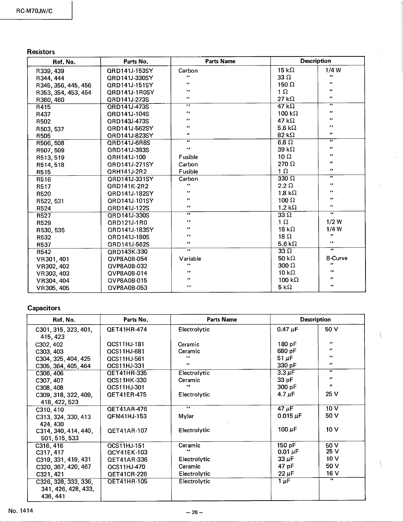
Resistors
Ref. No
R339, 439
R344, 444
R345, 356, 445, 456
354, 453, 454
R353,
R360, 460
R415
R437
R502
R503, 537
R505
R506, 508
R507, 509
R513, 519
R514, 518
R515
R516
R517
R520
R522, 531
R524
R527
R529
R530, 535
R532
R537
R542
VR301,401
VR302, 402
VR 303, 403
VR304, 404
VR305, 405
Capacitors
Ref. No.
, 315, 323, 401
415, 423
C302, 402
C303, 403
C304, 325, 404, 425
C305, 364, 405, 464
C306, 406
C307, 407
C308, 408
C309, 318, 322, 409
418, 422, 523
C310, 410
C313, 324, 330, 413
424, 430
C314, 340,
414, 440
501, 515, 533
C316, 416
C317,417
C319, 331,
419, 431
C320, 367, 420, 467
C321 , 421
C326, 328, 333, 336
341 , 426, 428, 433
436, 441
No. 1414
Parts No.
ORD141J-153SY
QRD141J-330SY
QRD141J-151SY
ORDI 41J-1 ROSY
QRD141J-273S
ORD141J-473S
QRD141J-104S
QRD143J-473S
ORD141J-562SY
ORD141J-823SY
QRD141J-6R8S
QRD141J-393S
QRH141J-100
ORD141J-271SY
QRH141J-2R2
QRD141J-331SY
QRD141K-2R2
QRD141J-182SY
QRD141J-101SY
QRD141J-122S
QRD141J-330S
QRD121J-1 RO
QRD141J-183SY
QRD141J-180S
QRD141J-562S
QRD143K-330
QVP8AOB-054
QVP8AOB-032
QVP8AOB-014
QVP8AOB-015
QVP8AOB-053
Parts No.
QET41HR-474
IHJ-181
OCSI IHJ-681
QCS11HJ-561
QCSI IHJ-331
OET41HR-335
QCSI 1HK-330
QCSI 1HJ.301
QET41ER-475
OET41AR-476
QFM41HJ-153
QET41AR-107
QCS11HJ-151
QCY41EK-103
QET41AR-336
QCSI 1HJ-470
QET41CR-226
QET41HR-105
Parts Name
Carbon
Fusible
Carbon
Fusible
Carbon
Variable
Parts Name
Electrolytic
Ceramic
Ceramic
Electrolytic
Ceramic
E lectrolytic
Mylar
Electrolytic
Ceram ic
Electrolytic
Ceramic
Ekctrolytic
Electrolytic
— 26 —
15
33 Q
150 Q
10
27 kQ
47 kQ
100
47 kO
5.6 kO
82
6.8 0
39 kO
100
270 0
10
330 0
2.2 Q
18 kO
100 Q
1.2
33 Q
10
18
180
5.6 kQ
33 Q
50 kQ
300 0
10 kO
100 kQ
0.47 uF
180 pF
680 pF
51
330 pF
3.3
33 pF
300 pF
4.7 uF
47 VF
0.015
100
150 pF
0.01
33 u F
47 pF
22
Description
1/2 w
1/4 w
B-Curve
Description
50 v
25 v
10 v
50 v
10 v
50 v
25 v
10 v
50 v
16 v
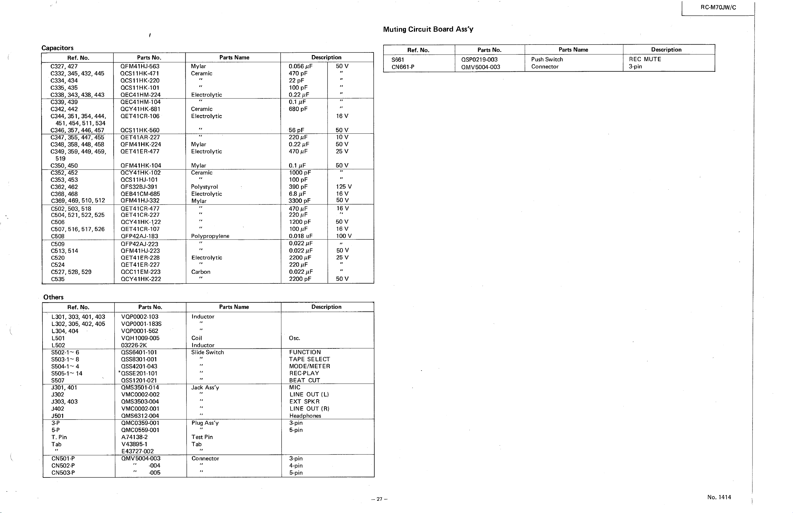
Muting Circuit Board Ass'y
Capacitors
Description
Ref. No.
$61
CN661+
Parts No.
OSP0219003
QMV5004-003
Parts Name
Push Switch
Connector
C327, 427
C334, 434
C335, 435
C338, 343,
C339, 439
C342, 442
451,
C346, 357,
C347, 355,
C348,
519
C350, 450
C352, 452
C353, 453
C362, 462
C368, 468
C369,
C506
C508
C509
C513, 514
C520
C524
Others
L302,
L304, 404
L501
L502
Ref. No
C332, 345, 432, 445
351,
454
358,
C349, 359, 449, 459
469,
C502, 503, 518
C504, 521, 522, 525
C507, 516, 517, 526
C527, 528, 529
Ref. No
L30T, 303, 401, 403
438, 443
354,
, 511,534
446, 457
447, 455
448, 458
510, 512
305, 402, 405
S502-1— 6
4
444,
Parts No.
QF M41HJ863
QCS11HK-471
QCS11HK-220
QCSIIHK-IOI
OEC41HM-224
QEC41HM-104
QCY41HK-681
QET41CR-106
QCS11HK-560
OET41AR-227
OFM41HK-224
QET41ER-477
OFM41HK-104
OCY41HK-102
QCSIIHJ-IOI
OFS32BJ-391
QEB41CM-685
OFM41HJ-332
QET41CR477
QET41CR-227
QCY41HK-1.22
QET41CR-107
OFP42AJ-183
QFP42AJ-223
QFM41HJ-223
QET41ER-228
QET41 ER-227
QCCI 1EM-223
QCY41HK-222
Parts No.
VQP0002-103
VQP0001-183S
VOP0001-562
VQH1009-005
03226-2K
QSS6401-101
QSS8301-001
*OSSE201-101
QSS1201-021
QMS3501-014
VMC0002002
QMS3503-004
VMC000201
QMS6312-004
OMC0359-001
OMC0559-001
A74138-2
V43895-1
E4372702
QMV5004-003
-004
-005
Parts Name
Mylar
Ceramic
Electrolytic
Ceramic
Electrolytic
Mylar
Electrolytic
Mylar
Ceramic
Polystyrol
Electrolytic
Mylar
Polypropylene
Electrolytic
Carbon
Parts Name
Inductor
Coil
Inductor
Slide Switch
Jack Ass'y
Plug Ass'y
Test Pin
Tab
Connector
0.056 1.IF
470 pF
22 pF
100 pF
0.22 pF
0.1 gF
680 pF
56 pF
220 pF
0.22
470 gF
0.1 VF
1000 pF
100 pF
390 pF
68
3300 pF
470
220 pF
1200 pF
100 gF
0.018 uF
0.022 pF
0.022 gF
2200 gr-
220
0.022 AF
2200 pF
50 v
16 v
50 v
10 v
50 v
25 v
50 v
125 v
16 v
50 v
16 v
50 v
16 v
100 v
50 v
25 v
50 v
S503-1& 8
S504-1
S505-1& 14
S507
J301, 401
J302
J303, 403
J402
J501
T. Pin
Tab
CN501-P
CN502*
CN503-P
Description
O sc.
FUNCTION
TAPE SELECT
MODE/METER
REC-PLAY
BEAT CUT
MIC
LINE OUT (L)
EXT SPKR
LINE OUT (R)
Head hones
3-pin
5-pin
3-pin
4-pin
5-pin
RC-M70JW/C
Description
REC MUTE
3-pin
No. 1414
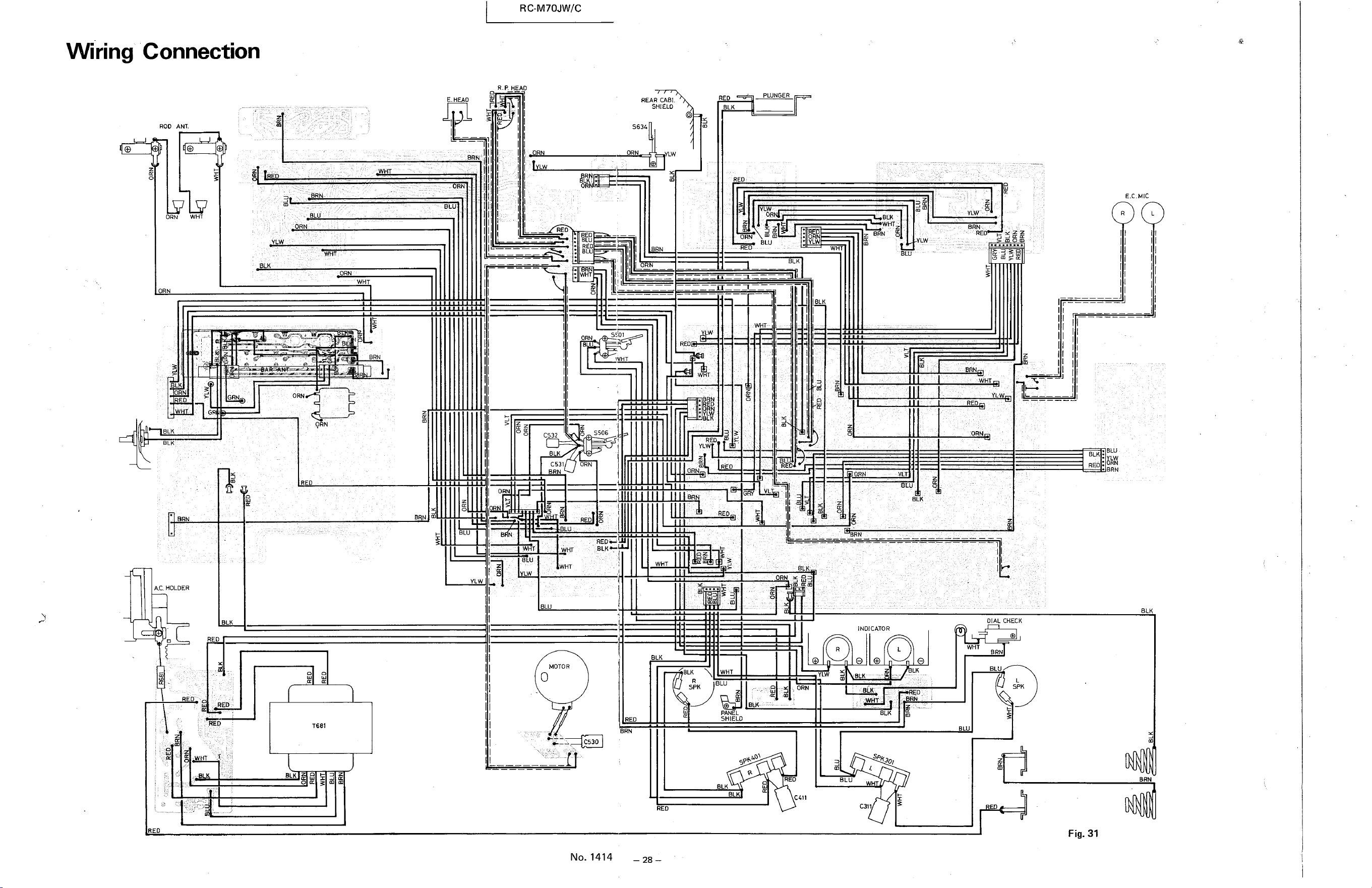
Wiring Connection
ROO ANT
E. HEAD
BRN
BLU
BLU
RC-M70JW/C
R.P HEAD
II I
ORN
REAR c.ABt.
SHIELD
S634
BLK
REO
PLUNGER
LIJ
WHT
ORN
YLW
WH
ORN
QRN
RED
32
C531 ORN
YtW
BLK
E.C.M[C
YLW
BLK
WHT
REO:
ELU
BLK
HOLDER
RED
REO
ORN
s:bl
RED — .U
BLK
BRN
BLK WHT
SPK
PANE L
SHIELD
ORN
BRN
LW
MOTOR
REO
BRN
C530
BLKo
INDICATOR
C31
REO
— 28 -
BLK
CIAL CHECK
WHY
BRN
BLU
Fig. 31
No. 1414
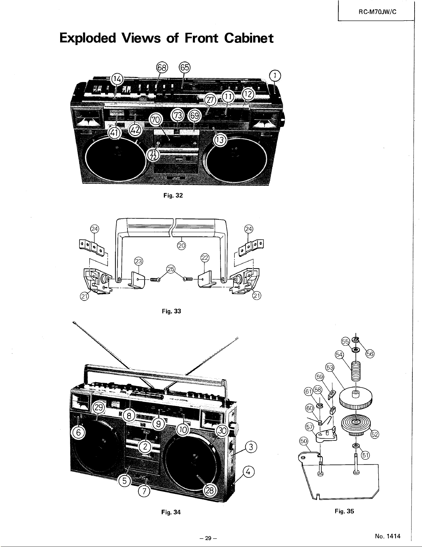
Exploded Views of Front Cabinet
68
70
42
1
73
12
11
27
69
41 —
13
21
Fig. 32
20
25
Fig. 33
10 30
21
29
Fig. 34
28
— 29 —
RC-M70JW/C
55
54
59
61 58
60
57
50
51
Fig. 35
No. 1414
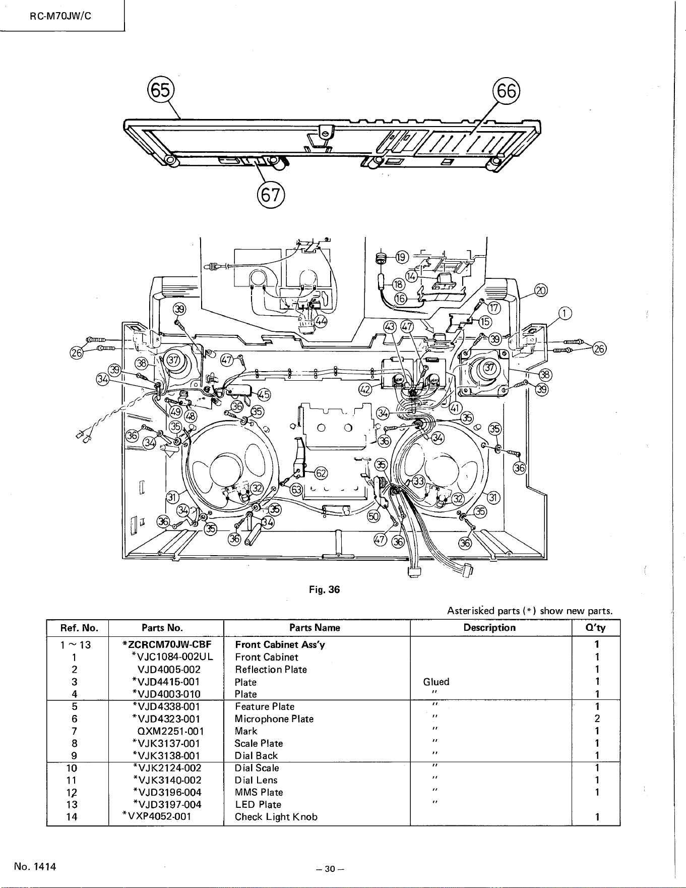
RC-M70JW/C
65
6
38 IN
39
67
9
14
18
16
43
39
49
48
35
33
0
41
32
66
17
15
-39
6
3
31
4
Ref. No.
1—13
1
2
3
4
5
6
7
8
9
10
11
12
13
14
No. 1414
5
63
O
6
Fig. 36
O
36
7
Asterisked parts (* ) show new parts.
Parts No.
*ZCRCM70JW-CBF
*VJC1084-002UL
VJD4005002
*VJD4415-001
*VJD4003-010
*VJD4338-001
*VJD4323-001
OXM2251-001
*VJK3137-001
*VJK3138-001
*VJK2124-002
K3140-002
*VJD3196-004
*VJD3197-004
*VXP4052-001
Parts Name
Front Cabinet Ass'y
Front Cabinet
Reflection Plate
Plate
Plate
Feature Plate
Micro phone Plate
Mark
Scale Plate
Dial Back
Dial Scale
Dial Lens
MMS Plate
LED Plate
Check Light Knob
— 30 —
Description
Glued
Q'ty
1
1
1
1
1
2
1
1
1
1
1
1
1
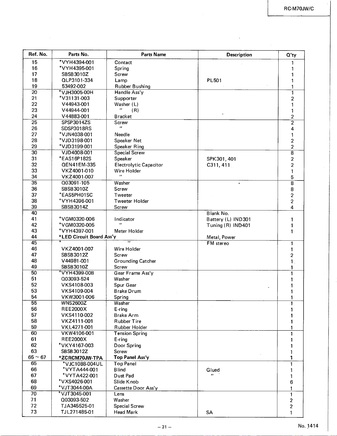
Ref. No.
15
16
17
18
19
20
21
22
23
24
25
26
27
28
29
30
31
32
33
34
35
36
37
38
39
40
41
42
43
44
45
46
47
48
49
50
51
52
53
54
55
56
57
58
59
60
61
62
63
65 67
65
66
67
68
69
70
71
72
73
Parts No.
*VYH4394-001
*VYH4395-001
SBSB3010Z
QLP3101-334
53492-002
*VJH3005-OOH
*V31131-003
v 44943-001
V 44944-001
V44883-001
SPSP3014ZS
SDSP3018RS
*VJN4038-001
*VJD3198-001
*VJD3199-001
VJD4008-001
*EAS16P182S
QEN41 EM-335
VKZ4001-010
VKZ400107
003091-105
SBSB3010Z
*EAS5PH01SC
*VYH4396-001
SBSB3014Z
*VGM0320-006
*VGM0320-005
*VYH4397-001
Parts Name
Contact
Spring
Screw
Lamp
Rubber Bushing
Handle Ass'y
Su pporter
Washer (L)
(R)
Bracket
Screw
Needle
Speaker Net
Speaker Ring
Special Screw
Speaker
Electrolytic Capacitor
Wire Holder
Washer
Screw
Tweeter
Tweeter Holder
Screw
Ind icator
Meter Holder
*LED Circuit Board Ass'y
VKZ4001-007
SBSB3012Z
V44981-001
SBSB3010Z
VYH4399-OOB
003093-524
VKS4108-003
VKS4109-004
VKW.3001-006
WNS2600Z
REE2000X
VKS4110-002
VKZ4111-001
VKL4271-001
VKW4106-001
REE2000X
*VKY4167-003
SBSB3012Z
*ZCRCM70JW-TPA
*VJC1088-004UL
*VYT A444-OO I
*VYT A422-001
XS4026-001
*VJT3044-OOA
VJT 3045-001
003093-502
TJL271485-01
Wire Holder
Screw
Grounding Catcher
Screw
Gear Frame Ass'y
W asher
Spur Gear
Brake Drum
Spring
Washer
E-ring
Brake Arm
Rubber Tire
Rubber Holder
Tension Spring
E-ring
Door Spring
Screw
Top Panel Ass'y
Top Panel
Blind
Dust Pad
Slide Knob
Cassette Door Ass'
Lens
Washer
Special Screw
Head Mark
Description
PL501
SPK301 , 401
C311, 411
Blank No.
Battery (L) IND301
Tuning (R) IND401
Metal, Power
FM stereo
Glued
SA
RC-M70JW/C
Q'ty
1
1
1
1
1
1
2
1
1
2
2
4
2
2
8
2
2
1
5
8
8
2
2
4
1
1
1
1
2
1
1
1
1
1
1
1
1
1
1
1
1
6
1
1
2
2
1
No. 1414
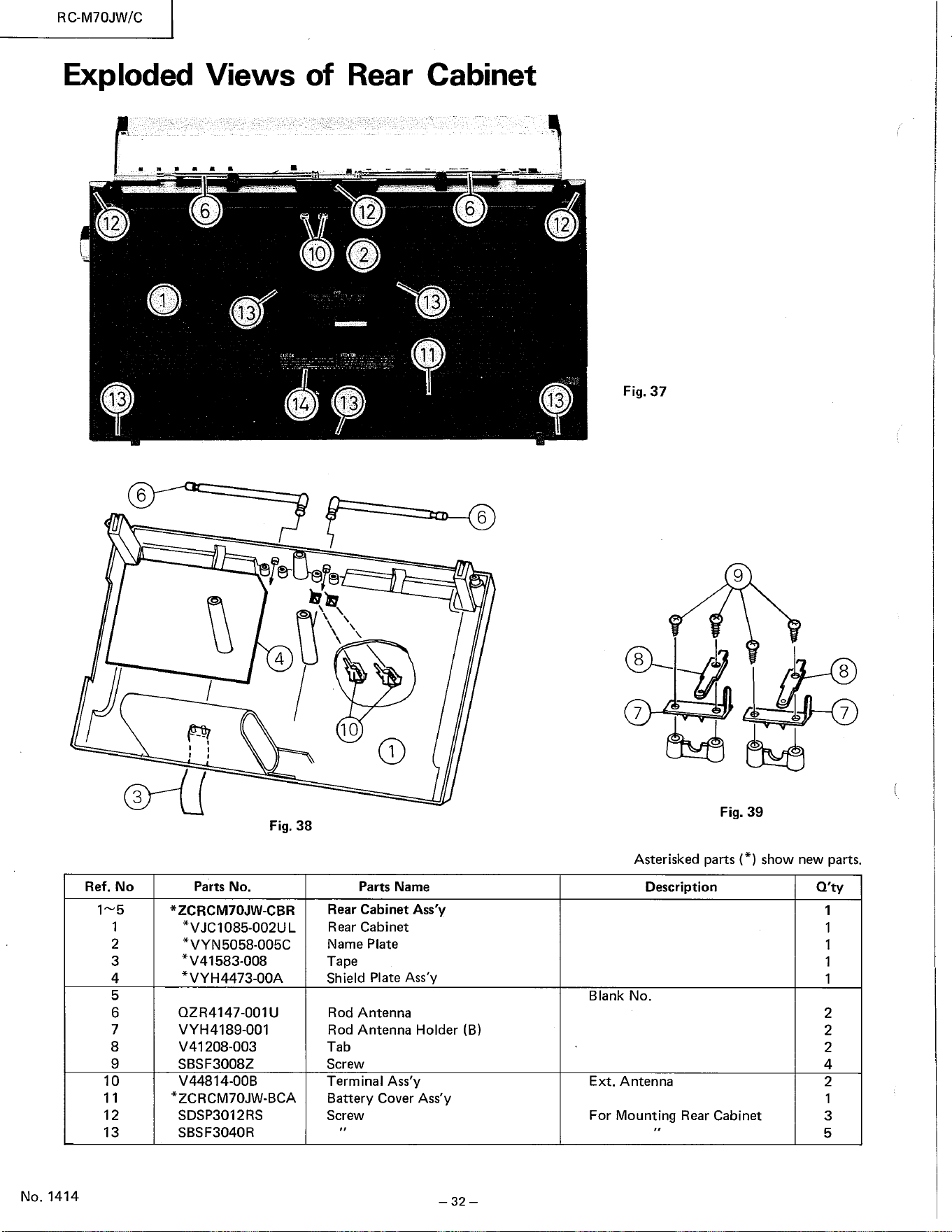
RC-M70JW/C
Exploded Views of
6
Rear
12
Cabinet
6
13
12
13
6
3
Ref. No
2
3
4
5
6
7
8
9
10
11
12
13
No. 1414
13
10
14
12
13
11
13
6
4
10
Fig. 38
Fig. 37
9
8
7
Fig. 39
8
7
Asterisked parts (*) show new parts.
Parts No.
*ZCRCM70JW-CBR
*VJC1085-002UL
*VYN5058-005C
*V41583-008
*VYH4473-OOA
QZR4147-001U
VYH4189-001
V41208-003
SBSF3008Z
V44814-OOB
*ZCRCM70JW-BCA
SDSP3012RS
SBSF3040R
Parts Name
Rear Cabinet Ass'y
Rear Cabinet
Name Plate
Tape
Shield Plate Ass'y
Rod Antenna
Rod Antenna Holder (B)
Tab
Screw
Terminal Ass'y
Battery Cover Ass'y
Screw
— 32 —
Description
Blank No.
Ext. Antenna
For Mounting Rear Cabinet
Q'ty
1
1
1
1
1
2
2
2
4
2
1
3
5
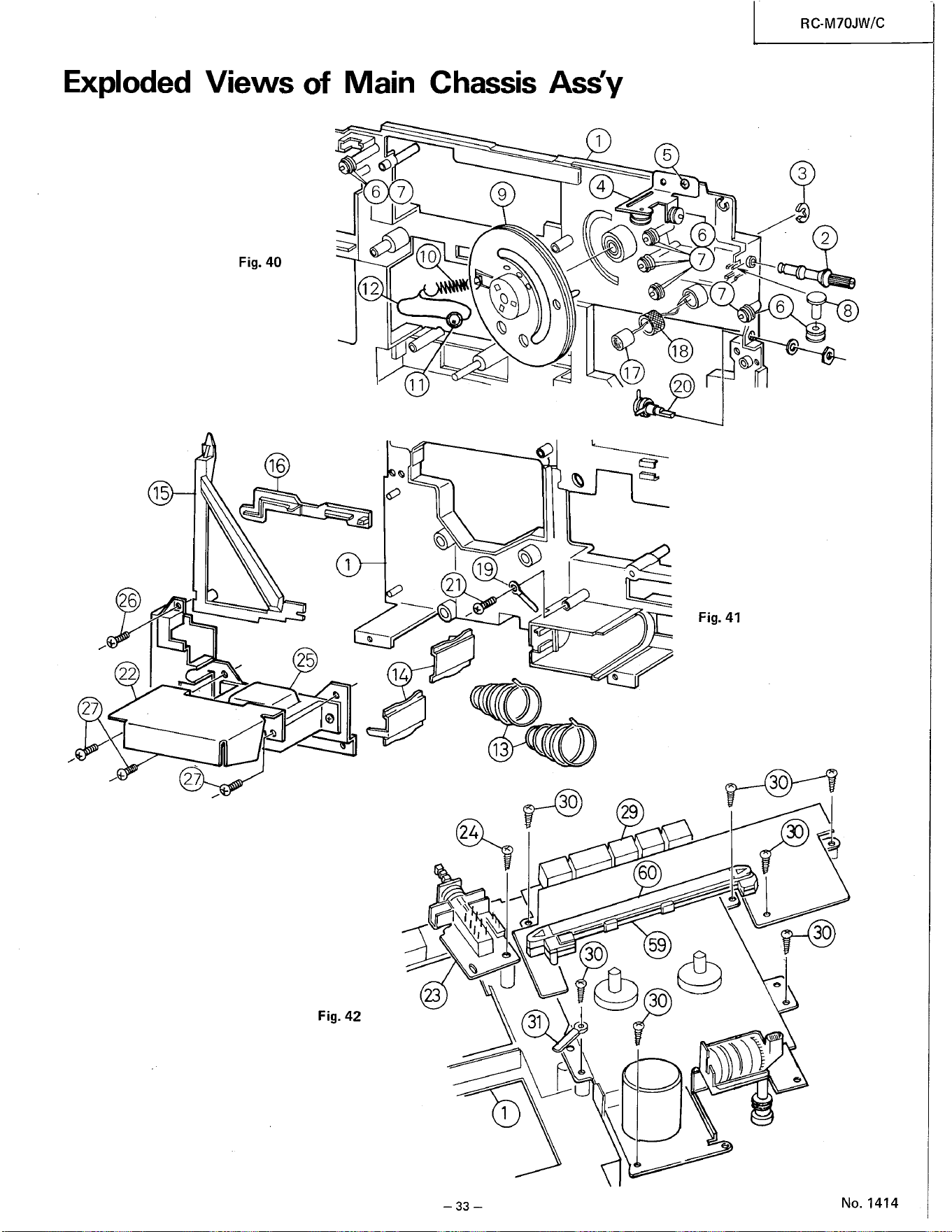
RC-M70JW/C
Exploded Views of Main Chassis Ass'y
10
Fig. 40
12
11
16
15
14
Fig. 42
21
13
31
— 33 —
18
17
20
Fig. 41
30
29
59
30
30
30
30
No. 1414
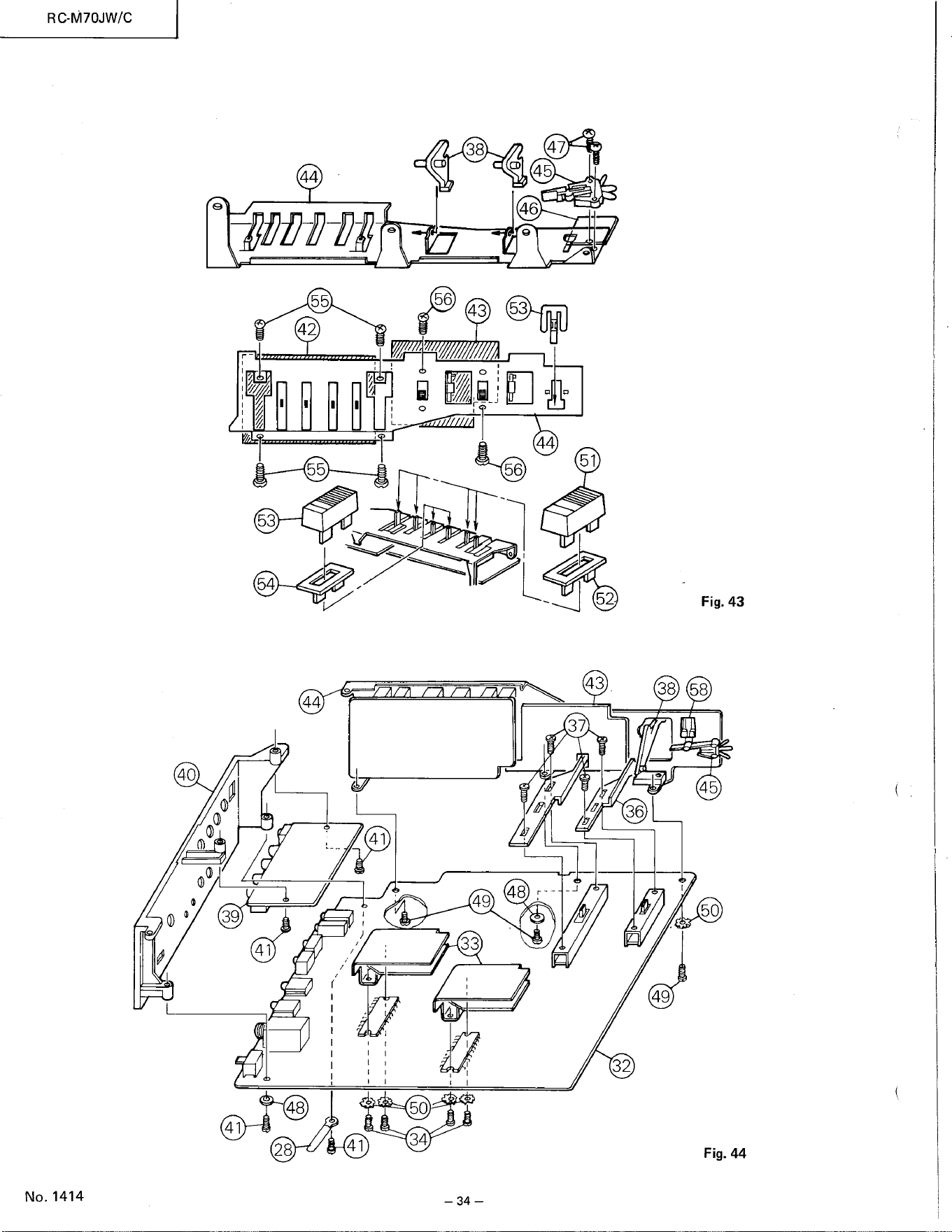
38
47
45
46
56
43 53
40
39
41
48
41
28
14
53
54
44
41
55
42
55
41
50
34
56
49 48
33
44
57
52
Fig. 43
43
38 58
45
36
50
49
32
Fig. 44
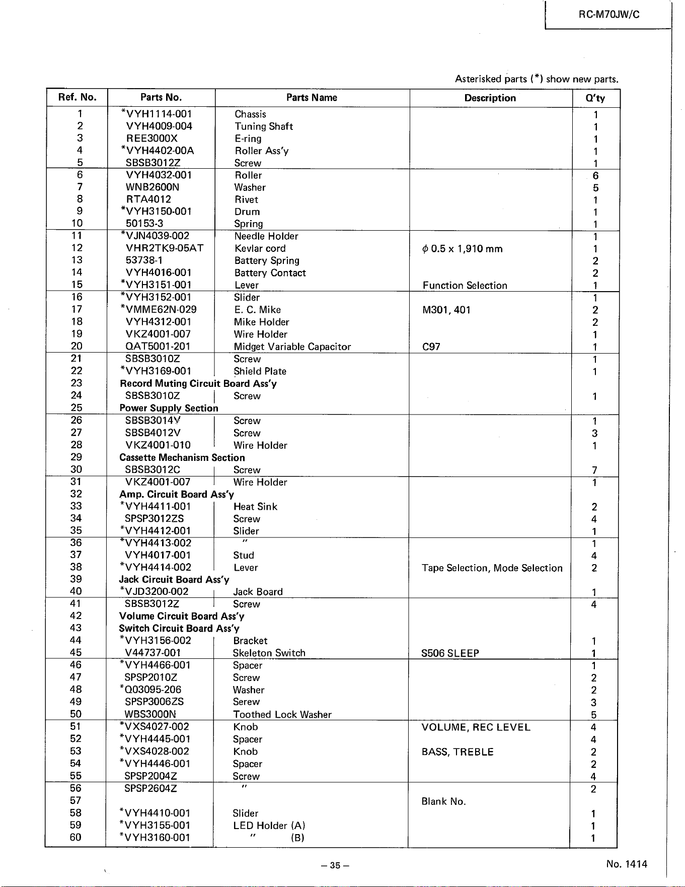
RC-M70JW/C
Asterisked parts (* ) show new parts.
Ref. No.
1
2
3
4
5
6
7
8
9
10
11
12
13
14
15
Function Selection
16
17
18
19
20
21
22
23
24
25
26
27
28
29
30
31
32
33
34
35
36
37
38
39
40
41
42
43
44
45
46
47
48
49
50
51
52
53
54
55
56
57
58
59
60
Parts No.
*VYHI 114-001
VYH4009-004
REE3000X
*VYH4402-OOA
SBSB3012Z
VYH4032-001
WNB2600N
RTA4012
*VYH3150-001
50153-3
VJN4039-002
VHR2TK9-05AT
53738-1
VYH4016-001
*VYH3151-001
*VYH3152-001
*VMME62N-029
VYH4312-001
V KZ4001-007
QAT5001-201
SBSB3010Z
*VYH3169-001
Parts Name
Chassis
Tuning Shaft
E-ring
Roller Ass'y
Screw
Roller
Washer
Rivet
Drum
Spring
Needle Holder
Kevlar cord
Battery Spring
Battery Contact
Lever
Slider
E. C. Mike
Mike Holder
Wire Holder
Midget Variable Capacitor
Screw
Shield Plate
Description
+0.5 x 1,
910 mm
Record Muting Circuit Board Ass'y
I Screw
SBSB3010Z
Power Suppl Section
SBSB3014V
SBSB4012V
VKZ4001-010
Screw
Screw
Wire Holder
Cassette Mechanism Section
SBSB3012C
V KZ400107
Screw
Wire Holder
Amp. Circuit Board Ass'y
*VYH4411-001
SPSP3012ZS
*VYH4412-001
VYH4413-002
VYH4017-001
*VYH4414-002
Jack Circuit Board Ass'y
*VJD3200-002
SBSB3012Z
Heat Sink
Screw
Slider
Stud
Lever
Jack Board
Screw
Volume Circuit Board Ass'y
Switch Circuit Board Ass'y
*VYH315602
V 44737-001
*VYH446601
SPSP2010Z
*003095-206
SPSP3006ZS
WBS3000N
*VXS4027-002
*VYH4445-001
*VXS4028-002
*VYH4446-001
SPSP2004Z
SPSP2604Z
*VYH4410-001
*VYH3155-001
*VYH3160-001
Bracket
Skeleton Switch
Spacer
Screw
Washer
Serew
Toothed
Knob
Spacer
Knob
Spacer
Screw
Slider
Lock Washer
M301 , 401
C97
Tape Selection, Mode Selection
S506 SLEEP
VOLUME, REC LEVEL
BASS, TREBLE
Blank No.
LED Holder (A)
(B)
— 35 —
Q'ty
1
1
1
1
6
5
1
1
1
1
1
2
2
1
1
2
2
1
1
1
1
1
1
3
1
7
1
2
4
1
1
4
2
1
4
1
1
1
2
2
3
5
4
4
2
2
4
2
1
1
1
No. 1414
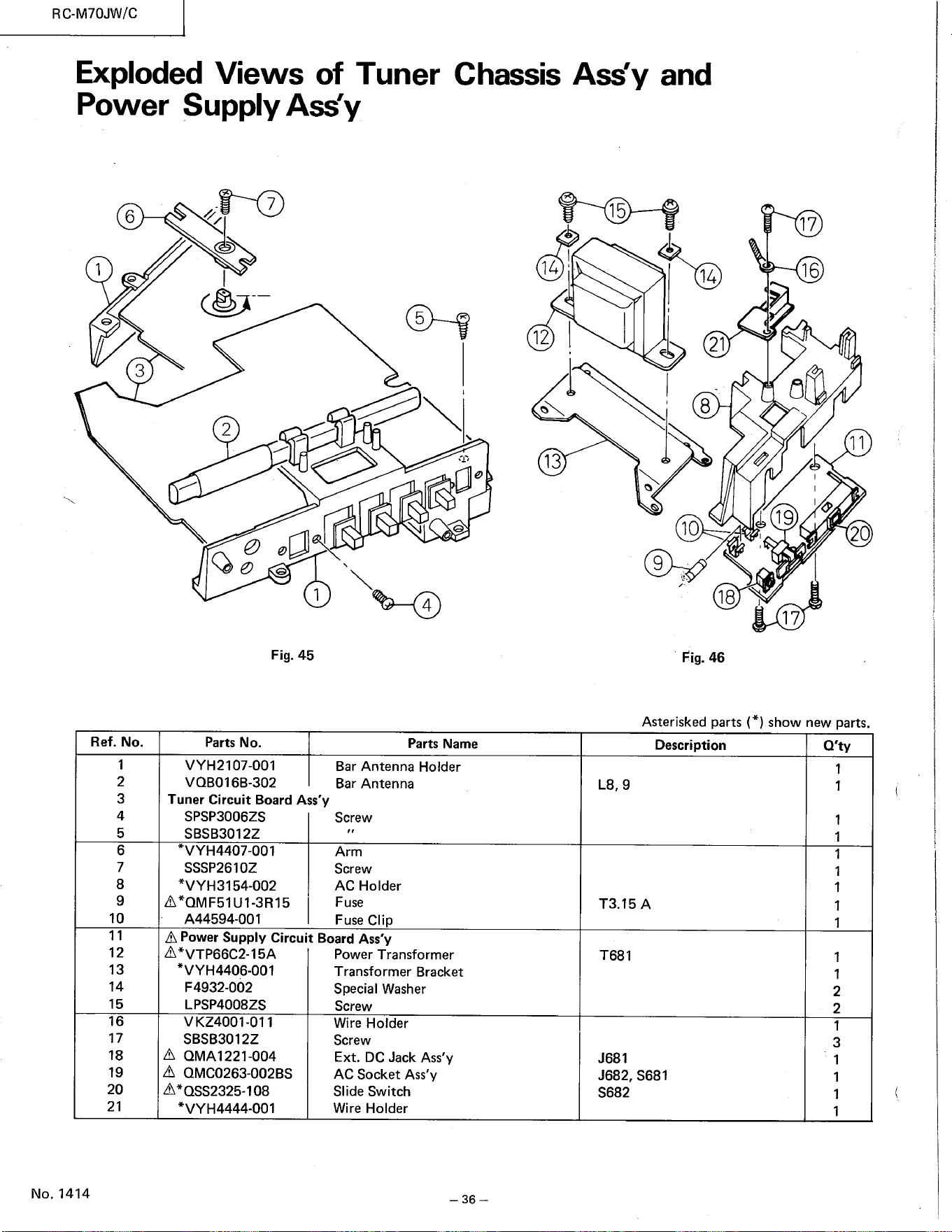
6
1
3
Ref. No.
1
2
3
4
5
6
7
8
9
10
11
12
13
14
15
16
17
18
19
20
21
No. 1414
RC-M70JW/C
Exploded Views of Tuner Chassis Ass'y and
Power Supply Ass'y
J682, S681
7
2
Fig. 45
Parts No.
VYH2107-001
VQB016B-302
Tuner Circuit Board Ass'y
SPSP3006ZS
SBSB3012Z
VYH4407-001
SSSP2610Z
*VYH3154-002
A*OMF51U1-3R15
A44594-OOI
15
5
4
Parts Name
Bar Antenna Holder
Bar Antenna
Screw
Arm
Screw
AC Holder
Fuse
Fuse Clip
14
12 |
13
14
21
8
9
18
Fig. 46
Description
17
16
11
19
20
T3.15A
A Power Supply Circuit Board Ass'y
A*VTP66C2-15A
*VYH4406-001
F 4932-002
LPSP4008ZS
VKZ4001-011
SBSB3012Z
A QMA1221-004
A QMC0263-002BS
A*QSS2325-108
*VYH4444-001
Power Transformer
Transformer Bracl<et
Special Washer
Screw
Wire Holder
Screw
Ext. DC Jack Ass'y
AC Socket Ass'y
Slide Switch
Wire Holder
— 36 —
T681
J681
S682
17
Asterisked parts (* ) show new parts.
Q'ty
1
1
1
1
1
1
1
1
1
2
2
1
3
1
1
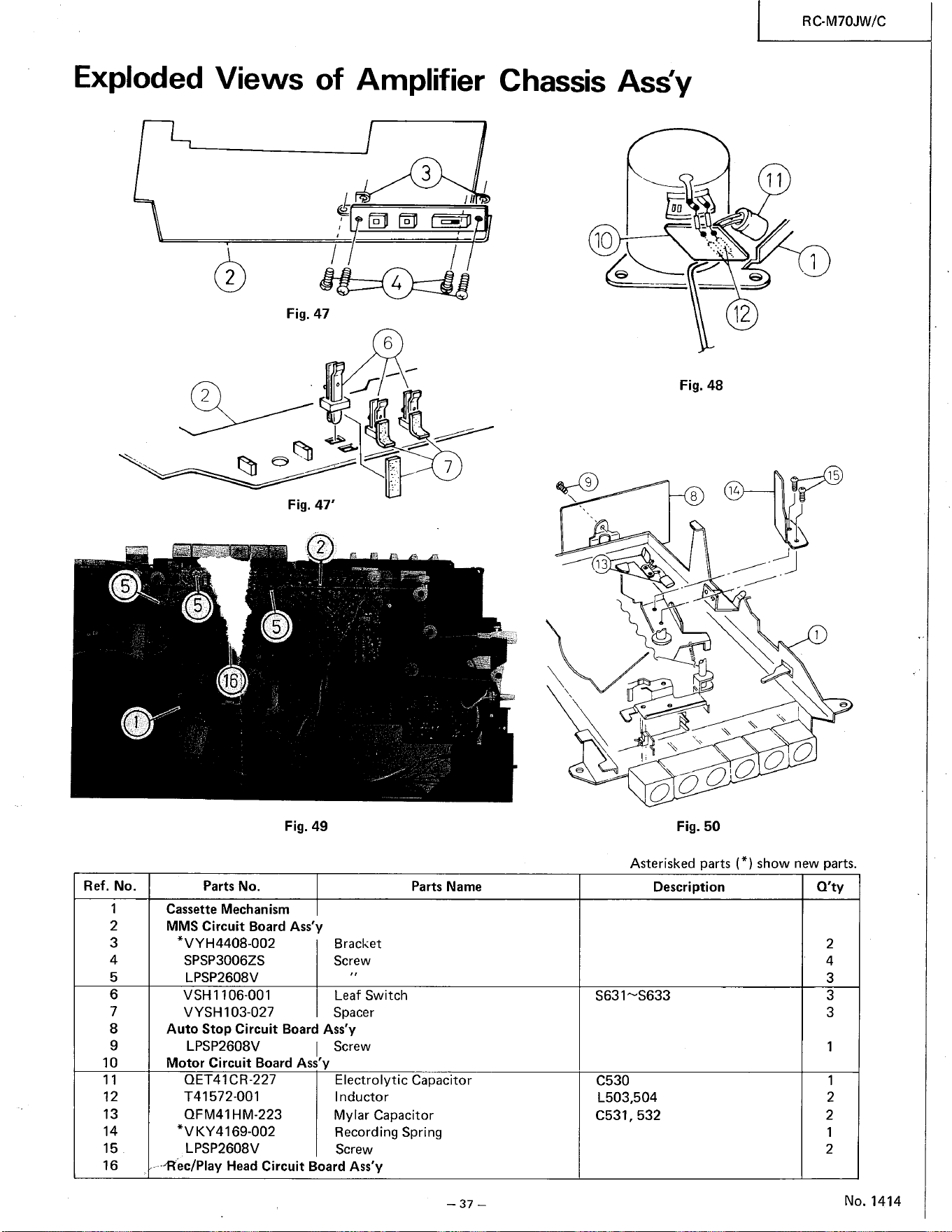
Exploded Views of Amplifier
3
Chassis Ass'y
00
10
RC.M70JW/C
11
1
15
5
Ref. No.
1
2
3
4
5
6
7
8
9
10
11
12
13
14
15
16
2
2
5
16
Parts No.
Fig. 47
Fig. 47'
2
5
Fig. 49
4
6
12
9
Fig. 48
8
7
Parts Name
13
C530
000000
Fig. 50
Asterisked parts (*) show new parts.
Description
Cassette Mechanism
MMS Circuit Board Ass'y
*VYH4408-002
SPSP3006ZS
LPSP2608V
VSHI 106-001
VYSH103-027
Bracket
Screw
Leaf Switch
Spacer
Auto Stop Circuit Board Ass'y
LPSP2608V Screw
Motor Circuit Board Ass'y
QET41CR-227
T41572-001
QFM41HM-223
*VKY4169-002
LPSP2608V
Electrolytic Capacitor
I nductor
Mylar Capacitor
Recording Spring
Screw
L503,504
C531 , 532
•-Rec/Play Head Circuit Board Ass'y
— 37 —
Q'ty
2
4
3
3
3
1
1
2
2
2
No. 1414
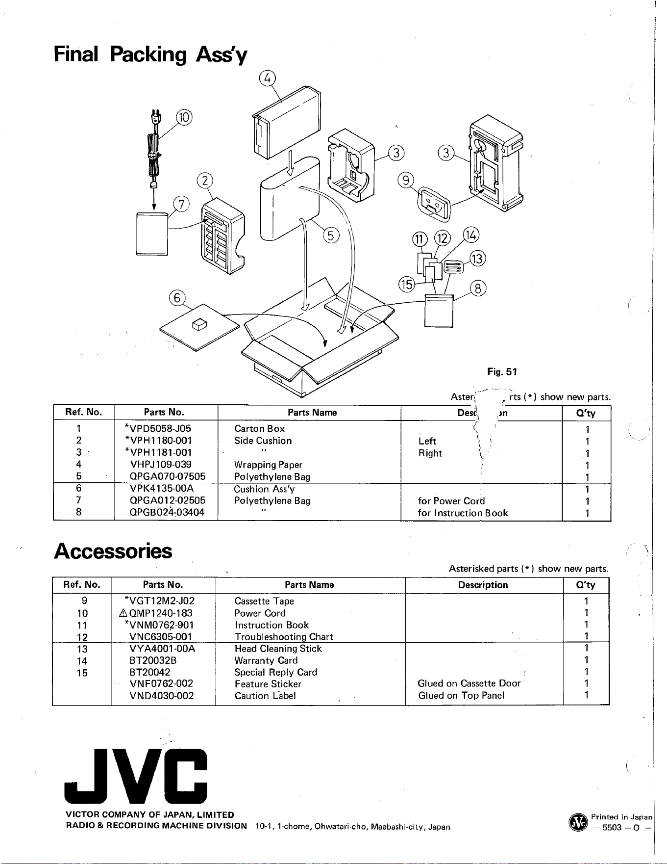
Final
Ref. No.
1
2
3
4
5
6
7
8
Packing Ass'y
10
2
7
6
Parts No.
*VPD5058-J05
*VPHI 180-001
*VPHI 181-001
VHPJ109-039
QPGA070-07505
VPK4135-OOA
QPGAOI 2-02505
QPGB02ä-03404
3
9
3
12
11
5
Parts Name
Carton Box
Side Cushion
Wrapping Paper
Polyethylene Bag
Cushion Ass'y
Polyethylene Bag
Parts Name
Cassette Tape
Power Cord
Instruction Book
Troubleshootin Chart
Head Cleaning Stick
Warranty Card
Special Reply Card
Feature Sticker
Caution Libel
15
Left
Right
14
13
8
Fig. 51
Aster!
Desé
for Power Cord
for Instruction Book
rts (* ) show new parts.
Q'ty
1
1
1
1
1
1
Accessories
Asterisked parts (* ) show new parts.
Ref. No.
9
10
11
12
13
14
15
Parts No.
*VGT12M2-J02
AOMP1240-183
*VNM0762-901
VYA4001-OOA
BT20032B
BT20042
VNF0762-002
VND4030-002
JVC
VICTOR COMPANY OF JAPAN, LIMITED
RADIO & RECORDING MACHINE DIVISION
10-1,
1-chome, Ohwatari-cho,
Description
Glued on Cassette Door
Glued on Top Panel
Maebashi-city, Japan
Q'ty
1
1
1
1
1
1
1
1
1
Printed in Japan
— 5503 —o —