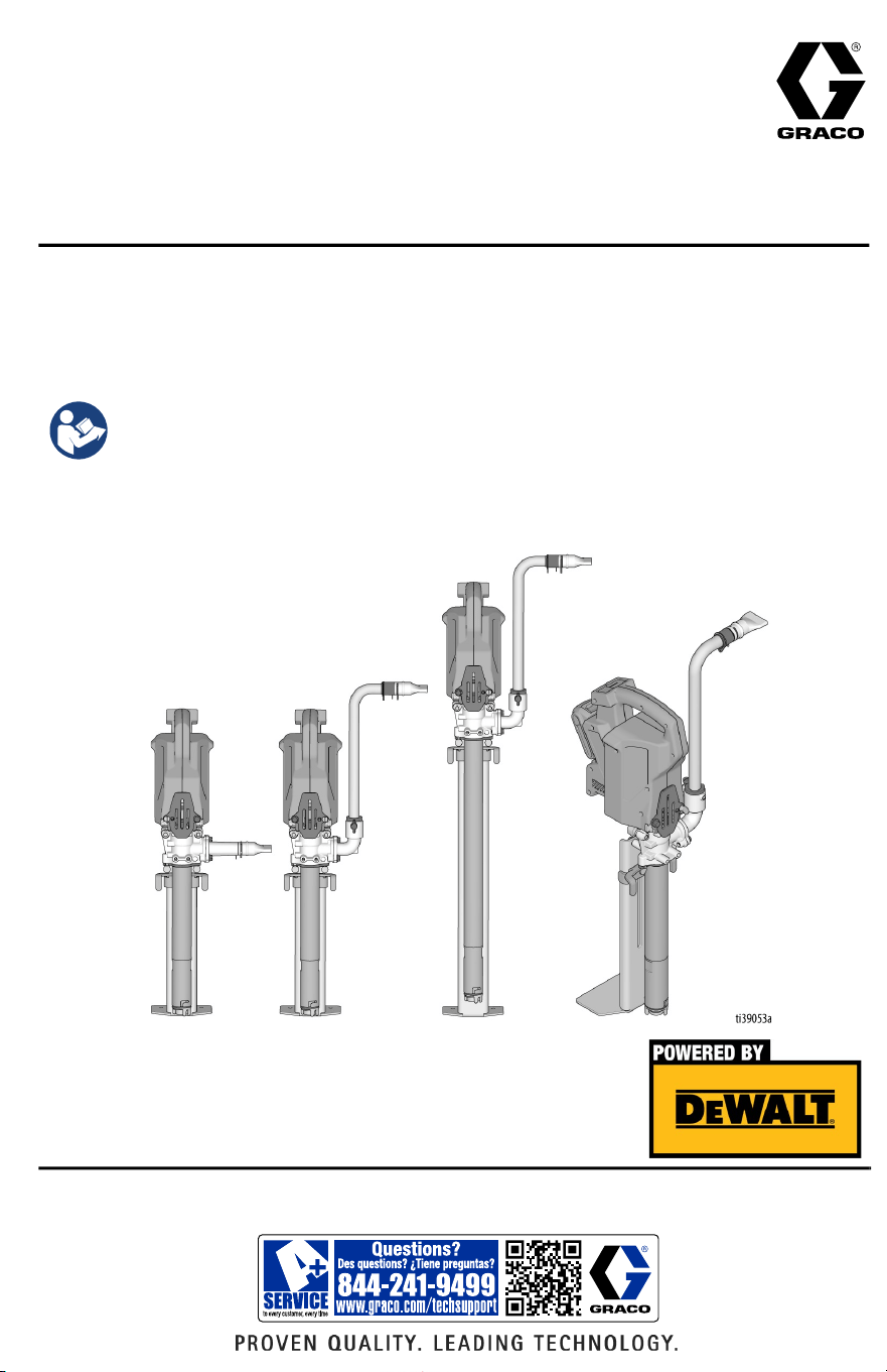
For portable dispensing of water-based and oil-based non-flammable materials.
Not approved for use in explosive atmospheres or hazardous (classified) locations.
For professional use only.
125 psi (0.86 MPa, 8.6 bar) Maximum Working Pressure
Important Safety Instructions
Read all warnings and instructions in this manual
before using the equipment. Be familiar with the
controls and the proper usage of the equipment.
Save these instructions.
3A8110D
EN
Operation, Parts
PowerFill™ 3.5 Standard Series, Pro
Series, and XL Pro Series
Use only genuine Graco replacement parts.
The use of non-Graco replacement parts may void warranty.

Contents
2 3A8110D
Contents
Models . . . . . . . . . . . . . . . . . . . . . . . . . . . . . . . . . . . . . . . . . . . . . 3
Important User Information . . . . . . . . . . . . . . . . . . . . . . . . . . . . 4
Warnings . . . . . . . . . . . . . . . . . . . . . . . . . . . . . . . . . . . . . . . . . . . 5
Component Identification . . . . . . . . . . . . . . . . . . . . . . . . . . . . . . 7
Setup . . . . . . . . . . . . . . . . . . . . . . . . . . . . . . . . . . . . . . . . . . . . . . 9
Configuration . . . . . . . . . . . . . . . . . . . . . . . . . . . . . . . . . . . . . 9
Standard Series Outlet Assembly . . . . . . . . . . . . . . . . . . . . . 11
Pro Series Outlet Assembly . . . . . . . . . . . . . . . . . . . . . . . . . 12
Box Filler . . . . . . . . . . . . . . . . . . . . . . . . . . . . . . . . . . . . . . . . 13
Battery Installation and Removal . . . . . . . . . . . . . . . . . . . . . 15
Start Up . . . . . . . . . . . . . . . . . . . . . . . . . . . . . . . . . . . . . . . . . . . 16
Operation . . . . . . . . . . . . . . . . . . . . . . . . . . . . . . . . . . . . . . . . . . 17
Pressure Relief Procedure . . . . . . . . . . . . . . . . . . . . . . . . . . 17
Using the Pump . . . . . . . . . . . . . . . . . . . . . . . . . . . . . . . . . . 18
Pro-Series Operation . . . . . . . . . . . . . . . . . . . . . . . . . . . . . . . . 19
Programming the Pump . . . . . . . . . . . . . . . . . . . . . . . . . . . . 19
Continuous Run Mode . . . . . . . . . . . . . . . . . . . . . . . . . . . . . 20
Cleaning . . . . . . . . . . . . . . . . . . . . . . . . . . . . . . . . . . . . . . . . . . . 21
Pump Re-assembly . . . . . . . . . . . . . . . . . . . . . . . . . . . . . . . 23
Pro Connect Removal and Assembly . . . . . . . . . . . . . . . . . . . 25
Power Head Removal . . . . . . . . . . . . . . . . . . . . . . . . . . . . . . 25
Troubleshooting . . . . . . . . . . . . . . . . . . . . . . . . . . . . . . . . . . . . 27
Parts . . . . . . . . . . . . . . . . . . . . . . . . . . . . . . . . . . . . . . . . . . . . . . 32
Technical Specifications . . . . . . . . . . . . . . . . . . . . . . . . . . . . . . 35
Recycling and Disposal . . . . . . . . . . . . . . . . . . . . . . . . . . . . . . 36
End of Product Life . . . . . . . . . . . . . . . . . . . . . . . . . . . . . . . . 36
California Proposition 65 . . . . . . . . . . . . . . . . . . . . . . . . . . . . . 36
Graco Standard Warranty . . . . . . . . . . . . . . . . . . . . . . . . . . . . . 37
Graco Information . . . . . . . . . . . . . . . . . . . . . . . . . . . . . . . . . . . 38
Models
3A8110D 3
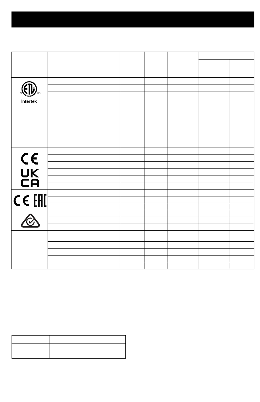
Models
Maximum working pressure 125 psi (0.86 MPa, 8.6 bar).
Compatible Batteries and Chargers
The PowerFill is compatible with DEWALT 18 Volt and 20 Volt MAX* batteries and chargers.
*Maximum initial battery voltage (measure without a workload) is 20 Volts. Nominal voltage is 18 Volts.
Related DEWALT Manuals
Approval Description Part
Charger
Voltage
Programmable
Dosing
Accessories
BackSaver
Fill Tube w/
Box Filler
Standard
Outlet w/
Box Filler
PowerFill 3.5 Standard Series
26B417 120V ✓
PowerFill 3.5 Pro Series
26B418 120V ✓ ✓
PowerFill 3.5 XL Pro Series
26B419 120V ✓ ✓
PowerFill 3.5 Standard Series
26B435 230V ✓
PowerFill 3.5 Pro Series
26B436 230V ✓ ✓
PowerFill 3.5 XL Pro Series
26B437 230V ✓ ✓
PowerFill 3.5 Standard Series, UK
26B536 230V ✓
PowerFill 3.5 Pro Series, UK
26B537 230V ✓ ✓
PowerFill 3.5 XL Pro Series, UK
26B538 230V ✓ ✓
PowerFill 3.5 Standard Series
26B439 230V ✓
PowerFill 3.5 Pro Series
26B440 230V ✓ ✓
PowerFill 3.5 XL Pro Series
26B441 230V ✓ ✓
PowerFill 3.5 Standard Series
26B442 230V ✓
PowerFill 3.5 Pro Series
26B443 230V ✓ ✓
PowerFill 3.5 XL Pro Series
26B444 230V ✓ ✓
PowerFill 3.5 Standard Series,
Japan
26B432 100V ✓
PowerFill 3.5 Pro Series, Japan
26B433 100V ✓ ✓
PowerFill 3.5 XL Pro Series, Japan
26B434 100V ✓ ✓
PowerFill 3.5 Pro Series, Korea
26B742 230V ✓ ✓
PowerFill 3.5 XL Pro Series, Korea
26B743 230V ✓ ✓
110474
Certified to
CAN/CSA
C22.2
No. 68
Conforms to
UL 1450
Ref. Description
N463494 Dewalt DCB118 Fast Charger
Manual

Important User Information
4 3A8110D
Important User Information
Thank You for Your Purchase!
Before using your pump read this Owners Manual for complete instructions on proper use and
safety warnings.
Congratulations! You have purchased a high-quality pump made by Graco Inc. This pump is
designed to provide superior performance with water-based and oil-based (mineral spirit-type)
coatings. This user information is intended to help you understand the types of materials that
can be used with your pump.
Please read the information on the material container label to determine if it can be used with
your pump. Ask for a Safety Data Sheet (SDS) from your supplier. The container label and SDS
will explain the contents of the material and the specific precautions related to it.
Paints, coatings and clean-up materials generally fit into one of the following 3 basic
categories:
WATER-BASED: The container label should indicate that the material can be
cleaned up with soap and water. Your pump is compatible with this type of
material. Your pump is NOT compatible with harsh cleaners such as chlorine
bleach.
OIL-BASED: The container label should indicate that the material is
COMBUSTIBILE and can be cleaned up with mineral spirits or non-flammable
paint thinner. The SDS must indicate that the flash point of the material is above
100°F (38°C). Your pump is compatible with this type of material. Use oil-based
material outdoors or in a well-ventilated indoor area with a flow of fresh air. See
the safety warnings in this manual.
FLAMMABLE: This type of material contains flammable solvents such as xylene,
toluene, naphtha, MEK, lacquer thinner, acetone, denatured alcohol, and turpentine.
The container label should indicate that this material is
FLAMMABLE. This type of material is NOT compatible with your pump
and CANNOT be used.
Warnings
3A8110D 5
Warnings
The following warnings are for the setup, use, grounding, maintenance, and repair of this equipment. The
exclamation point symbol alerts you to a general warning and the hazard symbols refer to
procedure-specific risks. When these symbols appear in the body of this manual or on warning labels, refer
back to these Warnings. Product-specific hazard symbols and warnings not covered in this section may
appear throughout the body of this manual where applicable.
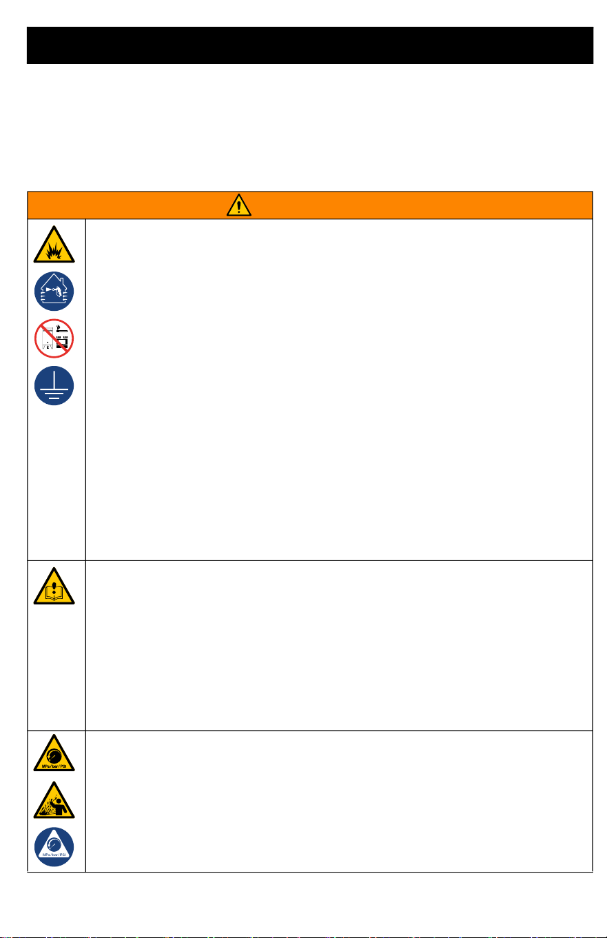
WARNING
FIRE AND EXPLOSION HAZARD
Flammable fumes, such as solvent and paint fumes, in work area can ignite or explode. To help
prevent fire and explosion:
• Do not pump or clean with materials having flash points lower than 100° F (38° C). Use
only non-flammable or water-based materials, or non-flammable paint thinners. For
complete information about your material, request the Safety Data Sheets (SDSs) from the
material distributor or retailer.
• Do not pump combustible materials near an open flame or sources of ignition such as
cigarettes, motors, and electrical equipment.
• Verify that all containers and collection systems are grounded to prevent static discharge.
Do not use pail liners unless they are anti-static or conductive.
• Do not use a paint or a solvent containing halogenated hydrocarbons.
• Do not pump combustible liquids in a confined area.
• Keep work area well-ventilated. Keep a good supply of fresh air moving through the area.
• Do not smoke in the work area or pump where sparks or flame is present.
• Do not operate light switches, engines, or similar spark producing products in the work
area.
• Keep area clean and free of paint or solvent containers, rags, and other flammable
materials.
• Know the contents of the paints and solvents being pumped. Read all Safety Data Sheets
(SDSs) and container labels provided with the paints and solvents. Follow the paint and
solvent manufacturer’s safety instructions.
• Keep a working fire extinguisher in the work area.
EQUIPMENT MISUSE HAZARD
Misuse can cause death or serious injury.
• Always wear appropriate gloves, eye protection, and a respirator or mask when
dispensing.
• Do not operate or dispense near children. Keep children away from equipment at all times.
• Do not overreach or stand on an unstable support. Keep effective footing and balance at
all times.
• Stay alert and watch what you are doing.
• Do not operate the unit when fatigued or under the influence of drugs or alcohol.
• Do not alter or modify equipment. Alterations or modifications may void agency approvals
and create safety hazards.
PRESSURIZED EQUIPMENT HAZARD
Fluid from the equipment, leaks, or ruptured components can splash in the eyes or on skin
and cause serious injury.
• Follow the Pressure Relief Procedure if you suspect the outlet tube is clogged, and
before cleaning, checking, or servicing equipment.
• Tighten all fluid connections before operating the equipment.
• Check tubes and couplings daily. Replace worn or damaged parts immediately.
Warnings
6 3A8110D
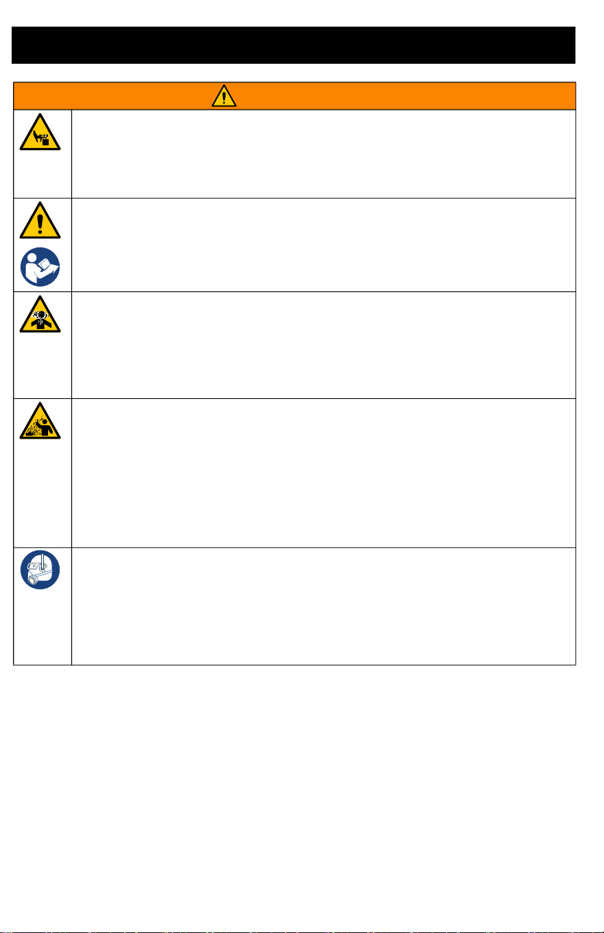
MOVING PARTS HAZARD
Moving parts can pinch, cut or amputate fingers and other body parts.
• Keep clear of moving parts.
• Do not operate equipment with protective guards or covers removed.
• Remove battery before cleaning, checking, or servicing equipment.
BATTERY AND CHARGER COMPATIBILITY HAZARD
•
Only use DEWALT brand 18V Max or 20V Max batteries and battery chargers with this tool.
• READ ALL INSTRUCTIONS included with this tool regarding the safety and usage of
DEWALT batteries and battery chargers.
TOXIC FLUID OR FUMES HAZARD
Toxic fluids or fumes can cause serious injury or death if splashed in the eyes or on skin,
inhaled, or swallowed.
• Read Safety Data Sheets (SDSs) to know the specific hazards of the fluids you are using.
• Store hazardous fluid in approved containers, and dispose of it according to applicable
guidelines.
PRESSURIZED ALUMINUM PARTS HAZARD
Use of fluids that are incompatible with aluminum in pressurized equipment can cause
serious chemical reaction and equipment rupture. Failure to follow this warning can result in
death, serious injury, or property damage.
• Do not use 1,1,1-trichloroethane, methylene chloride, other halogenated hydrocarbon
solvents or fluids containing such solvents.
• Do not use chlorine bleach.
• Many other fluids may contain chemicals that can react with aluminum. Contact your
material supplier for compatibility.
PERSONAL PROTECTIVE EQUIPMENT
Wear appropriate protective equipment when in the work area to help prevent serious injury,
including eye injury, hearing loss, inhalation of toxic fumes, and burns. Protective equipment
includes but is not limited to:
• Protective eyewear, and hearing protection.
• Respirators, protective clothing, and gloves as recommended by the fluid and solvent
manufacturer.
WARNING
Component Identification
3A8110D 7
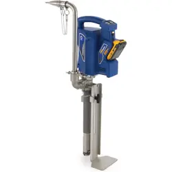
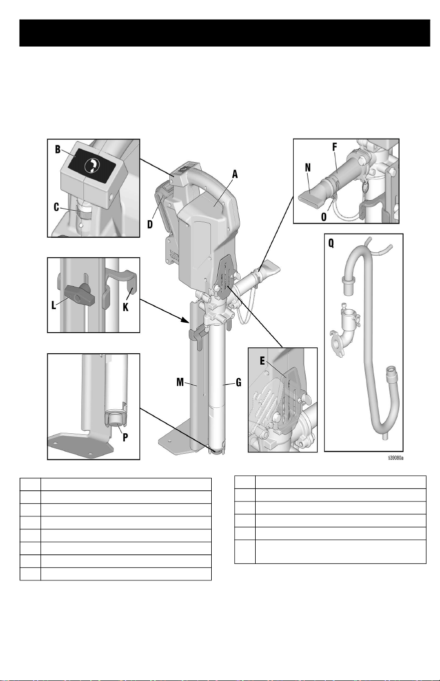
Component Identification
PowerFill 3.5 Standard Series
A Power Head
B Dispense button
C Speed control
D Battery
E ProConnect cover
F Standard series outlet
G Pump
K Bucket stabilizer
L Bucket stabilizer adjustment knob
M Stabilizing foot bracket
N Box filler nozzle
O Retaining clip
P Inlet filter
Q Goose neck and pro series outlet
(optional accessory)
Component Identification
8 3A8110D
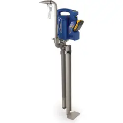
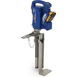
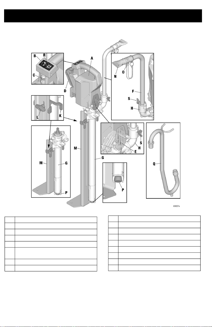
PowerFill 3.5 Pro and XL Pro Series
A Power Head
B Dispense button
C Speed control
D Battery
E ProConnect cover
F 14 in. Hi-Rise fill tube (23 in. High-Rise
kit optional accessory)
G Pump
H Pro series outlet
K Bucket stabilizer
L Bucket stabilizer adjustment knob
M Stabilizing foot bracket
N Box filler nozzle
O Retaining clip
P Inlet filter
Q Goose-neck (optional accessory)
R Program/repeat button
S Locking tube wing bolt
Setup
3A8110D 9
Setup
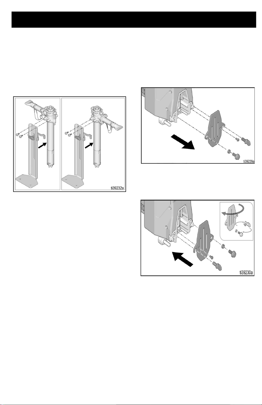
Configuration
The PowerFill is capable of being set-up with
the outlet on the left or right, depending on
user preference.
To change orientation, proceed with the
following steps.
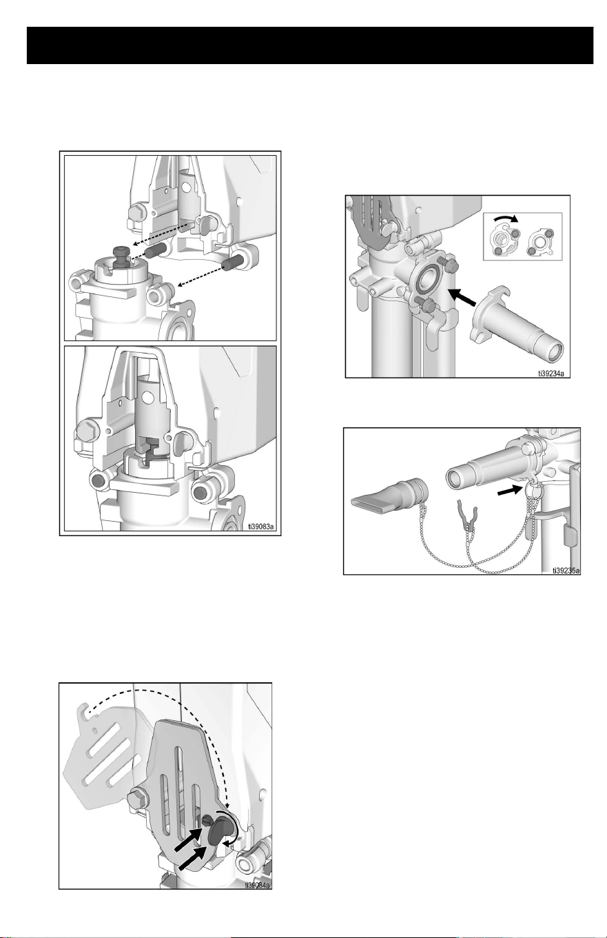
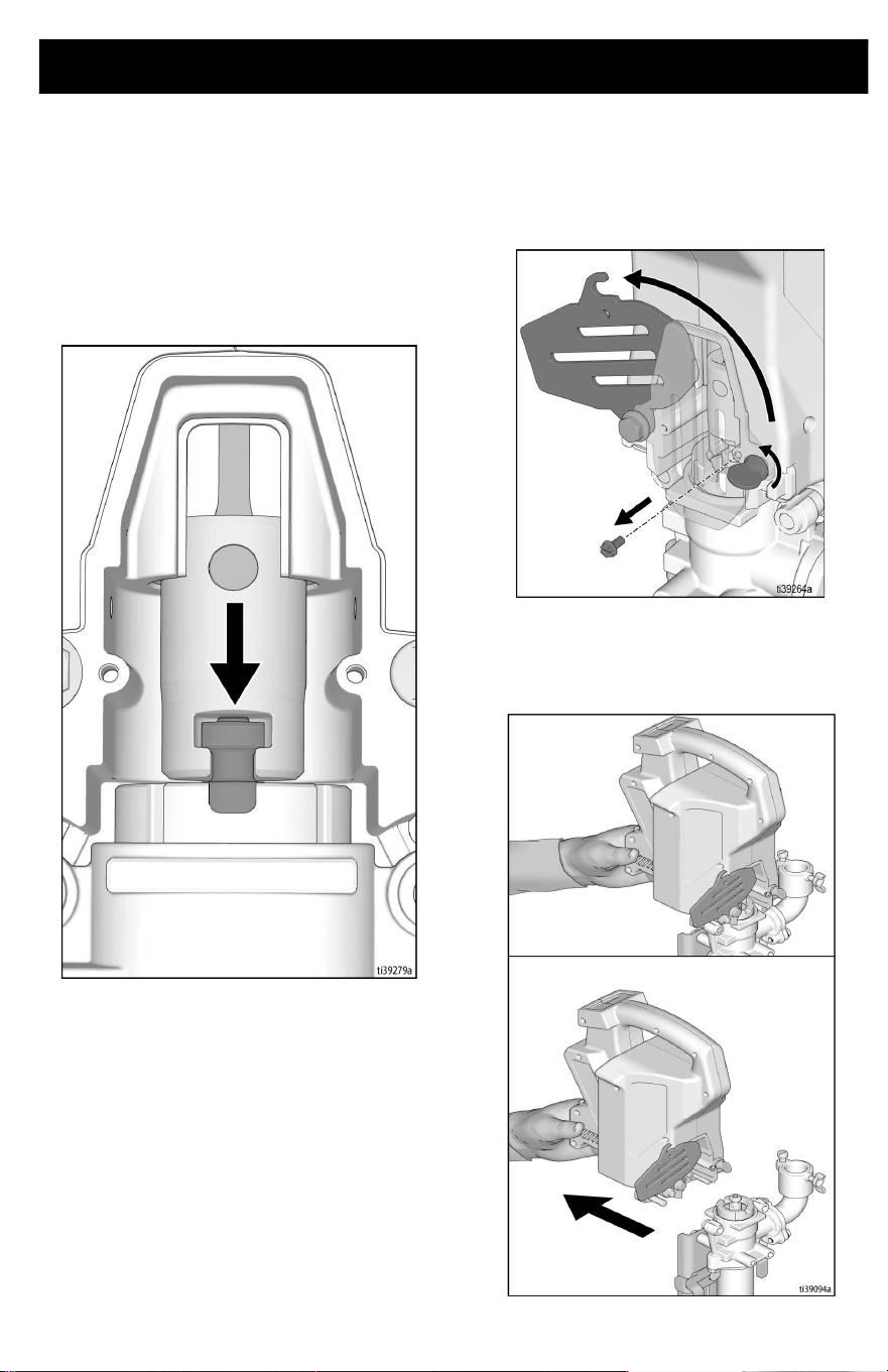
ProConnect Cover Orientation
The ProConnect cover holds the pump in
place and is a guard for the pump rod. To
ensure Power Head is easy to remove and
install, the ProConnect cover needs to swing
away from outlet tube. To change the
orientation of the ProConnect cover, follow
the steps below.
1. Remove battery, see Battery
Installation and Removal, page 15.
2. Disconnect Power Head from pump, if
necessary. See Power Head Removal,
page 25.
3. Using a 1/4 in. nut driver, remove the
locking screw. Remove thumb screw.
Using a 1/2 in. (or 13 mm) wrench,
remove flanged bolt and spacer.
4. Flip ProConnect cover to rotate opposite
way. Re-assemble flange bolt with
spacer, locking screw, and thumb screw
to secure.
Setup
10 3A8110D
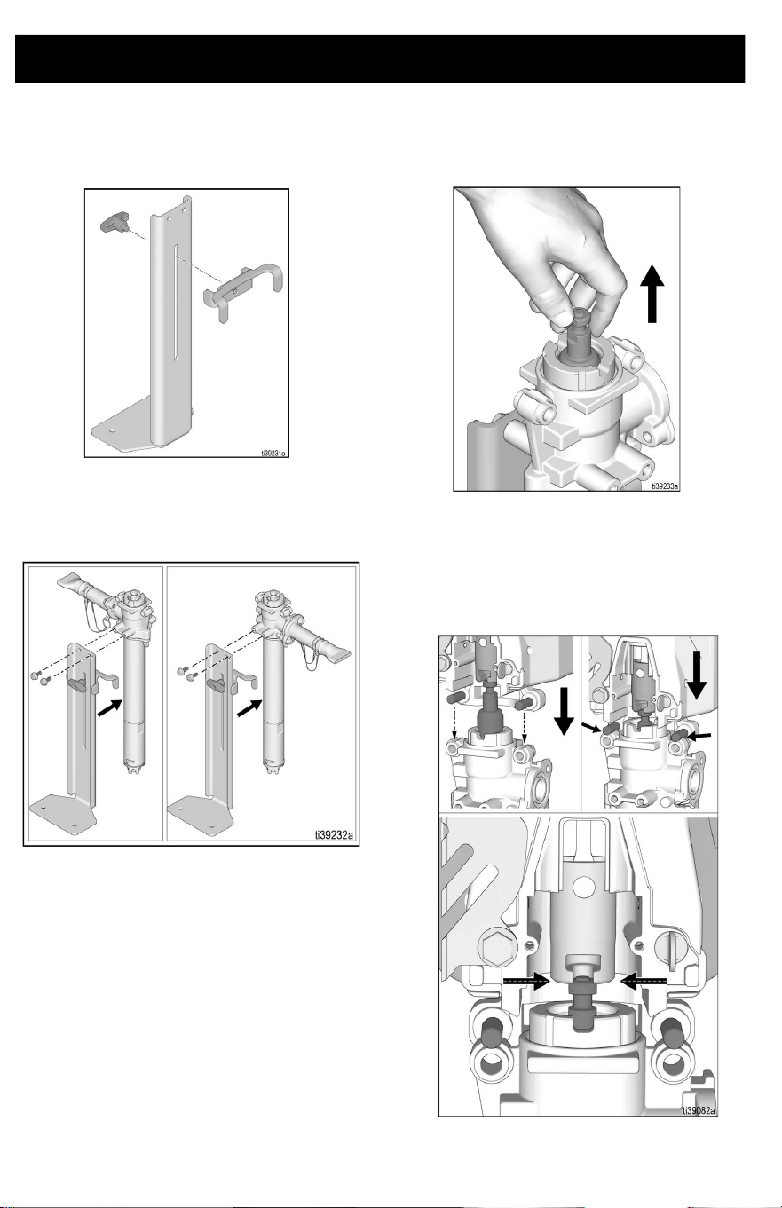
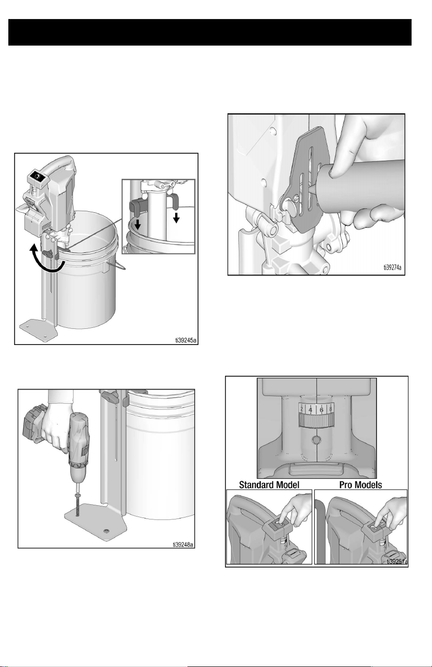
Foot Bracket and Bucket Stabilizer
1. Attach sliding bracket to foot stand with
provided thumb screw.
2. Using a 1/2 in. (or 13 mm) wrench,
assemble 5/16 - 18 flange bolts,
assemble foot bracket in desired
orientation and torque to 18 ft.-lbs.
Power Head
1. If necessary, pull piston upwards so
slider will contact piston head.
2. Place slider on top of piston head.
3. Align piston head by slowly pressing
piston downward with the Power Head
until pins on Power Head rest atop the
pump frame.
Setup
3A8110D 11
4. Attach Power Head by inserting pins into
the holes on the pump. Power Head
should automatically align with piston
head once step 3 is complete.
NOTE: Ensure piston is properly inserted into
the Power Head prior to operation. Should
piston not align into the Power Head,
manually pull the piston up and re-align.
5. Close ProConnect cover and tighten
thumb screw to secure Power Head.
Ensure locking screw is installed before
operation.
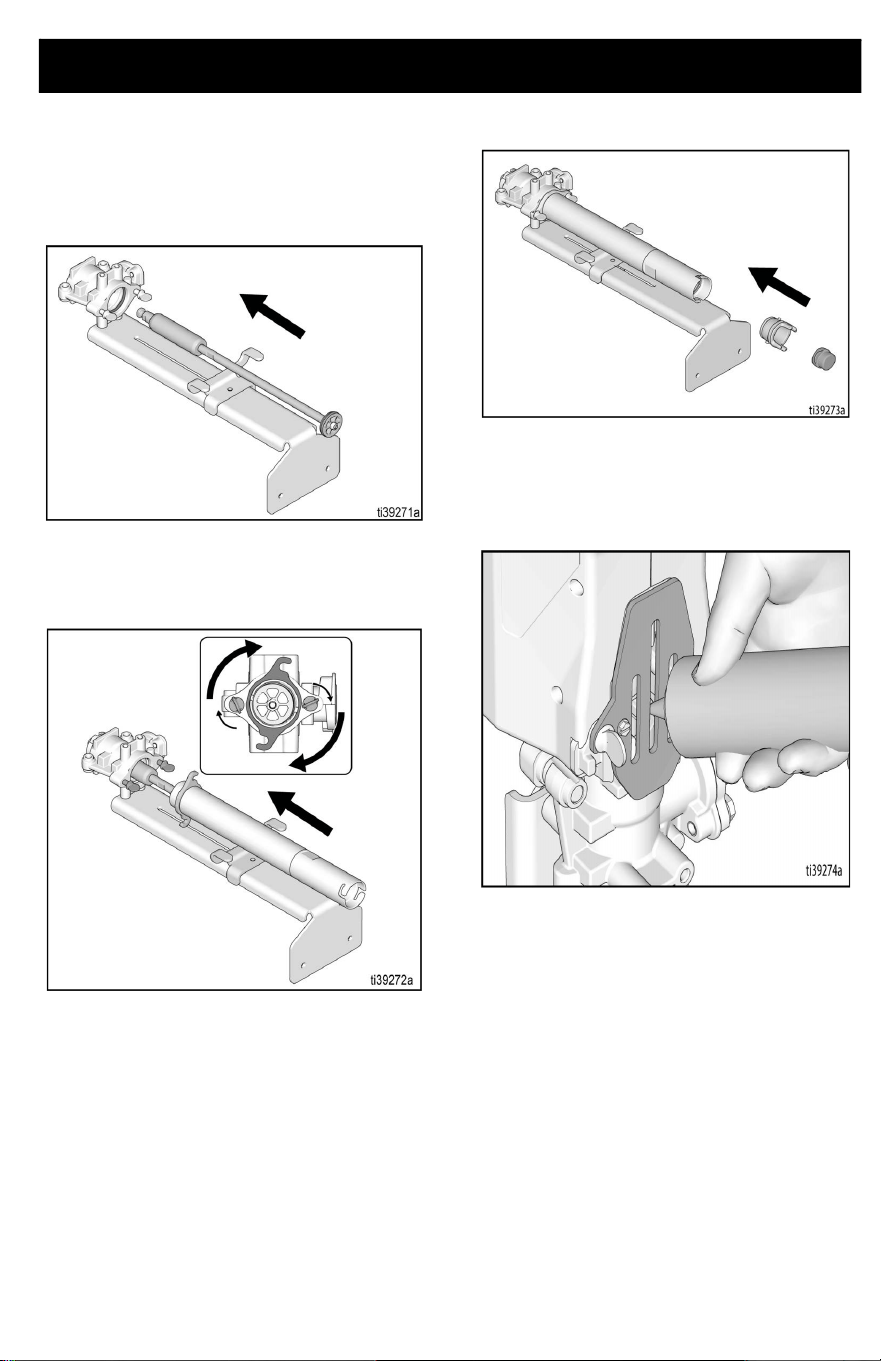
Standard Series Outlet
Assembly
1. Assemble standard outlet to pump and
using a 1/2 in. or 13 mm wrench, tighten
flange head bolts.
2. Assemble ring to standard series outlet
tab.
Setup
12 3A8110D
Pro Series Outlet
Assembly
1. Assemble Pro Series outlet to pump and
using a 1/2 in. or 13 mm wrench, tighten
flange head bolts.
2. Assemble Hi-Rise fill tube assembly by
aligning scallop on tube with bolt located
on the outlet fitting and insert it into the
outlet assembly. Lubricate with water or
grease if necessary. Rotate tube to
secure.
3. Hand tighten wing bolt to hold tube in
desired location.
Setup
3A8110D 13
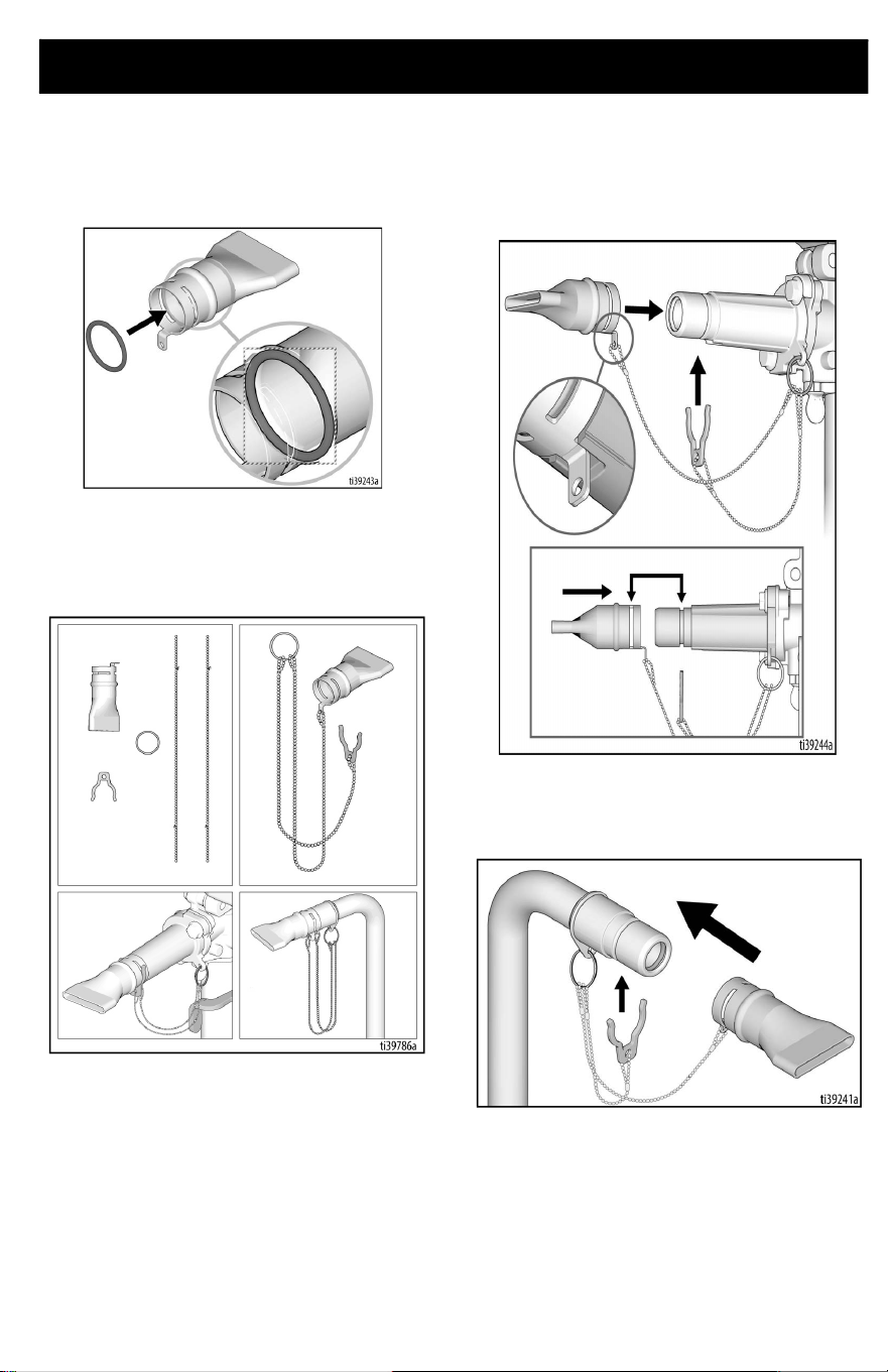
Box Filler
1. Ensure o-ring is in groove of box filling
attachment.
2. Assemble box filling attachment,
lanyard, and retaining clip. Connect
assembly to outlet tube or standard
outlet.
3. Align anti-rotation tab on box filler with
cutout on outlet fitting and push the box
filler on until the slot and groove are
aligned. If difficult to push on, lubricate
parts with water or grease.
4. Insert retaining clip through groove to
prevent box filling attachment from
disconnecting during operation.
Setup
14 3A8110D
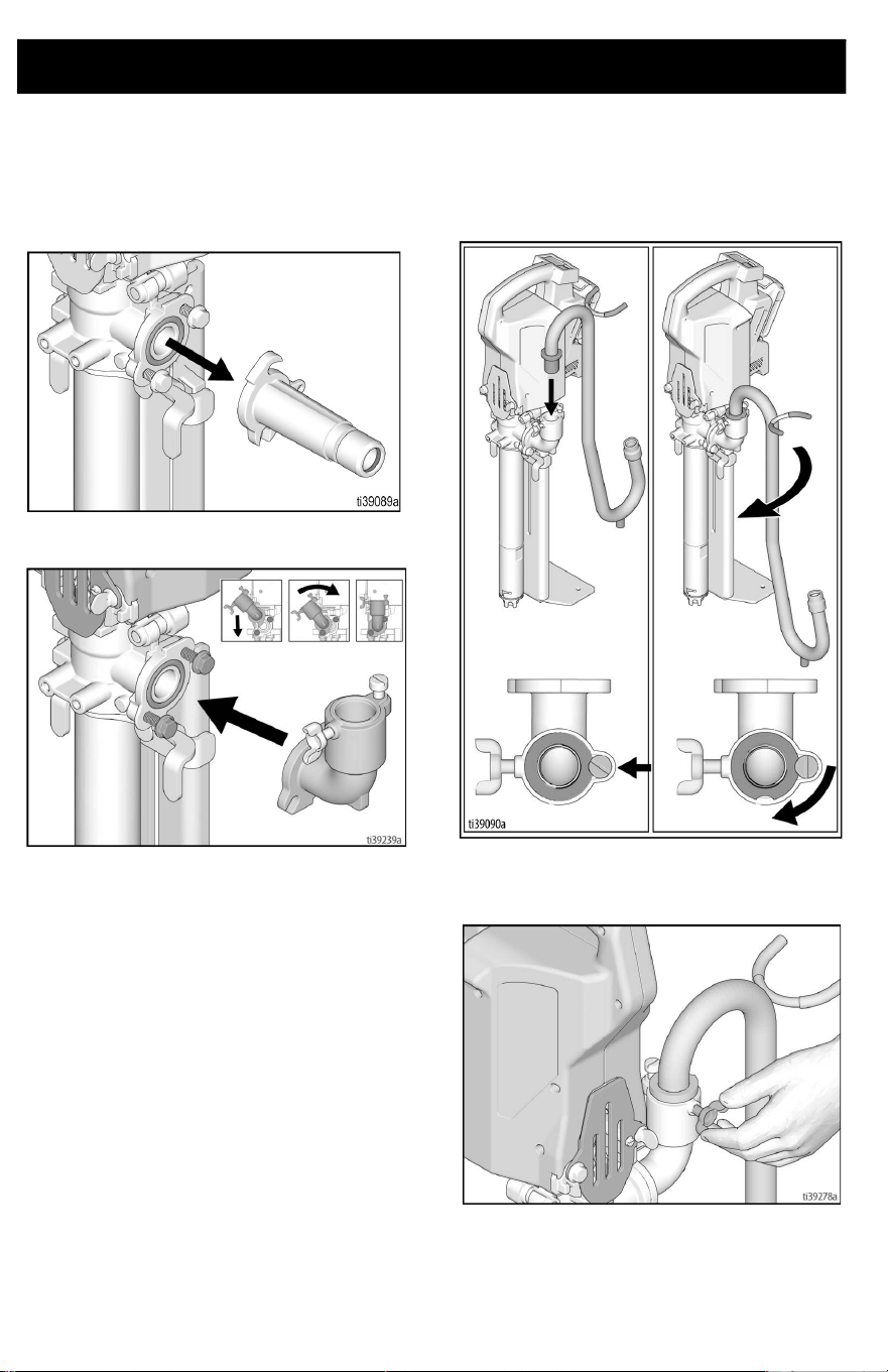
Goose Neck Assembly (Optional
Accessory)
1. Remove standard series outlet, if
necessary, by loosening flange bolts.
2. Attach Pro Series outlet.
3. Align scallop on goose neck with bolt
located on the outlet fitting and insert it
into the outlet assembly. Lubricate with
water or grease if necessary. Rotate
tube to secure.
4. Hand tighten wing bolt to hold
goose-neck in desired location.
Setup
3A8110D 15
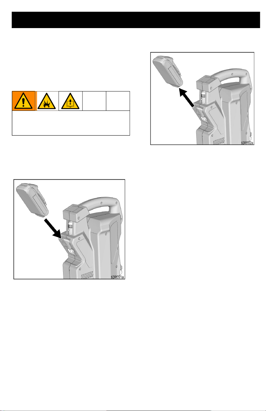
Battery Installation and
Removal
Always start with a fully charged Battery.
Do not splash or immerse Battery or
charger in water. See Battery and charger
information shipped with the pump.
Remove and install Battery into the pump as
follows:
1. To install, align battery into the grooves
on unit and slide into place until it fully
seats.
2. To remove, press button on the back of
the battery and pull battery from unit.
Replace and charge Battery only in a
well-ventilated area and away from
flammable or combustible materials.
Start Up
16 3A8110D
Start Up
1. Prior to dispensing, mix material as
necessary.
2. Insert pump into bucket of material and
adjust the bucket stabilizing bracket to
desired height.
3. If desired, secure foot bracket to
mounting surface to increase stability.
4. Apply Throat Seal Liquid (TSL) into
pump throat.
5. Install battery on the Power Head, see
Battery Installation and Removal,
page 15.
6. Set speed control to setting 5 and press
pump dispense button to prime the unit
until material comes out of the outlet port
(~5 seconds).
NOTE: If unit doesn’t prime within 10
seconds of pumping, pour water into outlet to
wet pump and repeat. If pump doesn’t prime,
refer to Troubleshooting, page 27.
Operation
3A8110D 17
Operation
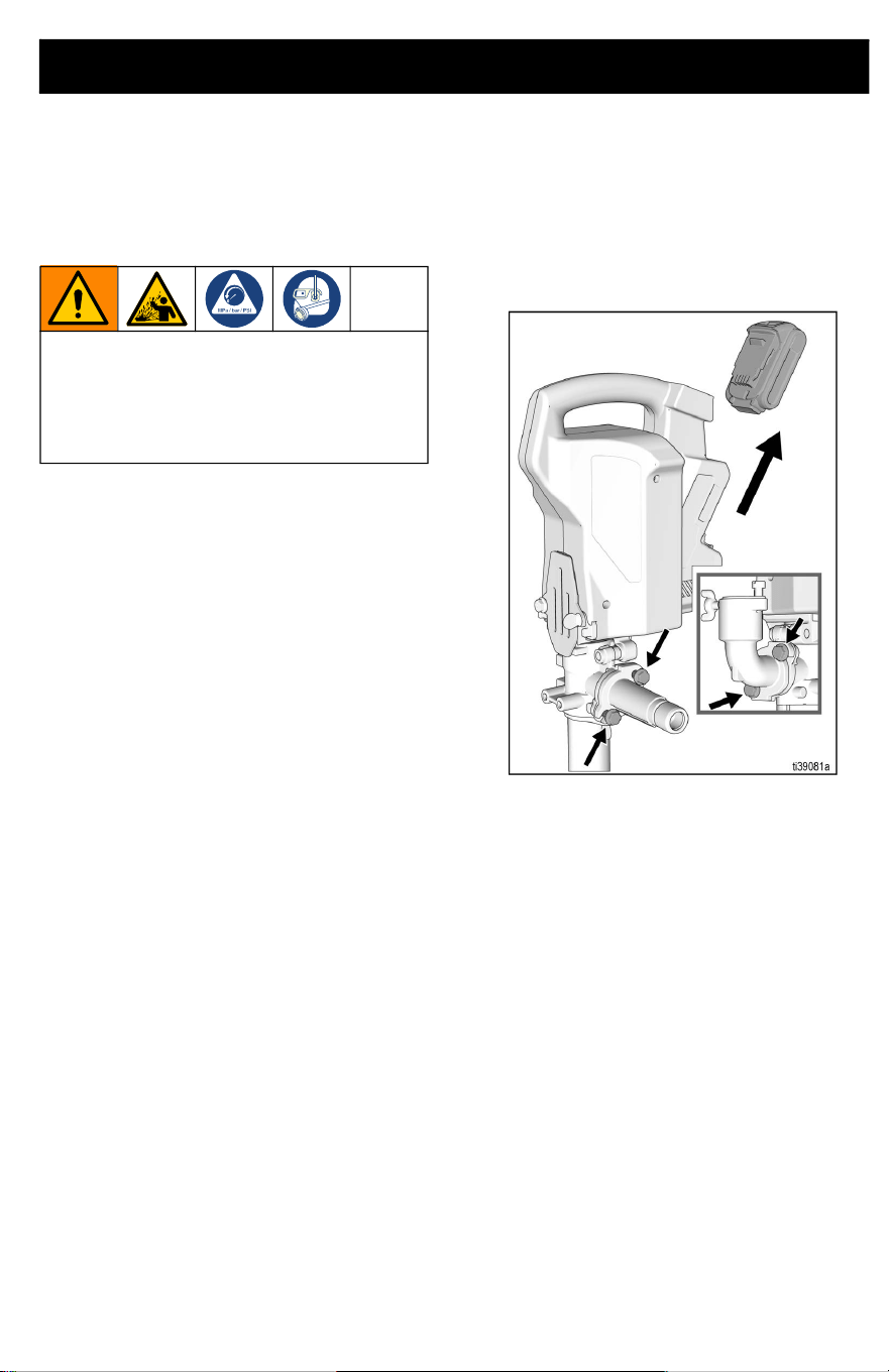
Pressure Relief Procedure
In normal use, the PowerFill automatically
relives pressure when the pump is switched
off. If outlet tube becomes plugged pressure
may be trapped in the pump. Follow the steps
below to relieve trapped pressure.
1. Remove battery from pump, see Battery
Installation and Removal, page 15.
2. Slowly remove flange bolts shown below
until pressure is relieved.
To help prevent serious injury from
pressurized fluid or splashed fluid, follow
the Pressure Relief Procedure before
pump is cleaned, and before equipment is
serviced.
Operation
18 3A8110D
Using the Pump
1. Insert battery into Power Head, see
Battery Installation and Removal,
page 15.
2. To operate pump, press and hold
dispense button. Releasing the
dispense button will stop the pump.
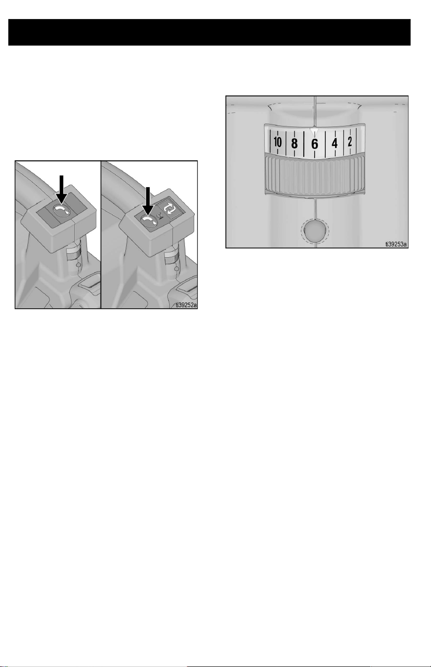
3. The variable speed control allows users
to select the pump speed for precise
dispensing, depending on application.
Pro-Series Operation
3A8110D 19
Pro-Series Operation
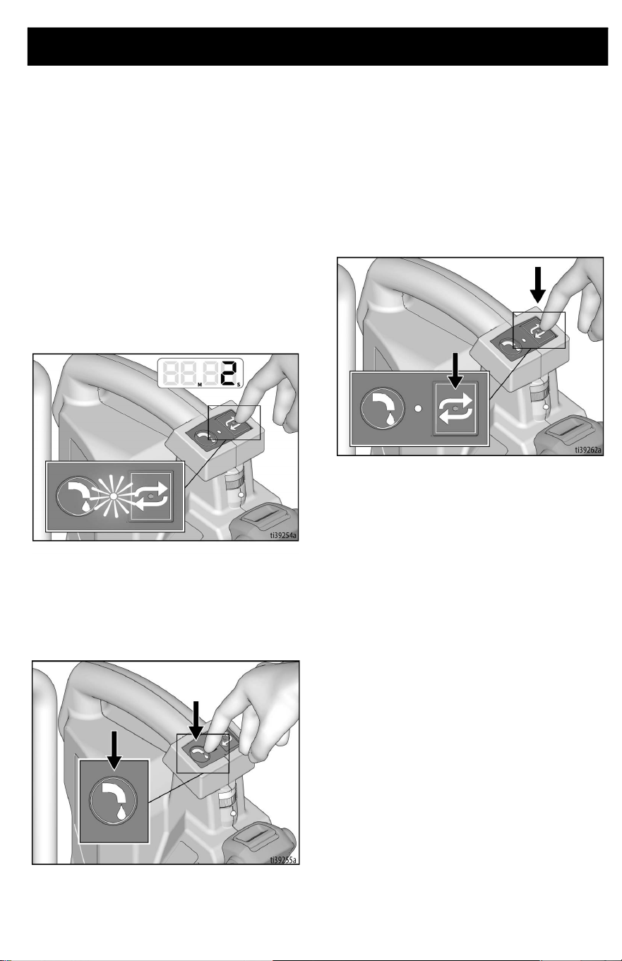
Programming the Pump
The Pro-Series features a program/repeat
button that allows the user to program a
volume of material they want to repeatedly
dispense. After programming the unit, the
pump will repeat that volume with a single
press and release of the repeat button.
To program the pump, follow the steps below.
1. To enter program mode, press and hold
down the repeat button for two seconds
until the red LED light begins to blink.
2. While the LED light is blinking, press the
dispense button until the desired amount
of material is pumped. This can be one
continuous press, or numerous presses
of the dispense button.
3. While the LED light is still blinking, press
and release the repeat button to set the
program for that volume of material and
to exit programming mode. This must be
completed within 10 seconds of
releasing the dispense button or it will
not save the program.
4. To pump the programmed volume, press
and release the repeat button. If the
button is held longer than two seconds,
unit will revert back to programming
mode.
5. If you want to interrupt the pumping,
press any button and the unit will stop.
The next press of the repeat button starts
the program over.
Pro-Series Operation
20 3A8110D
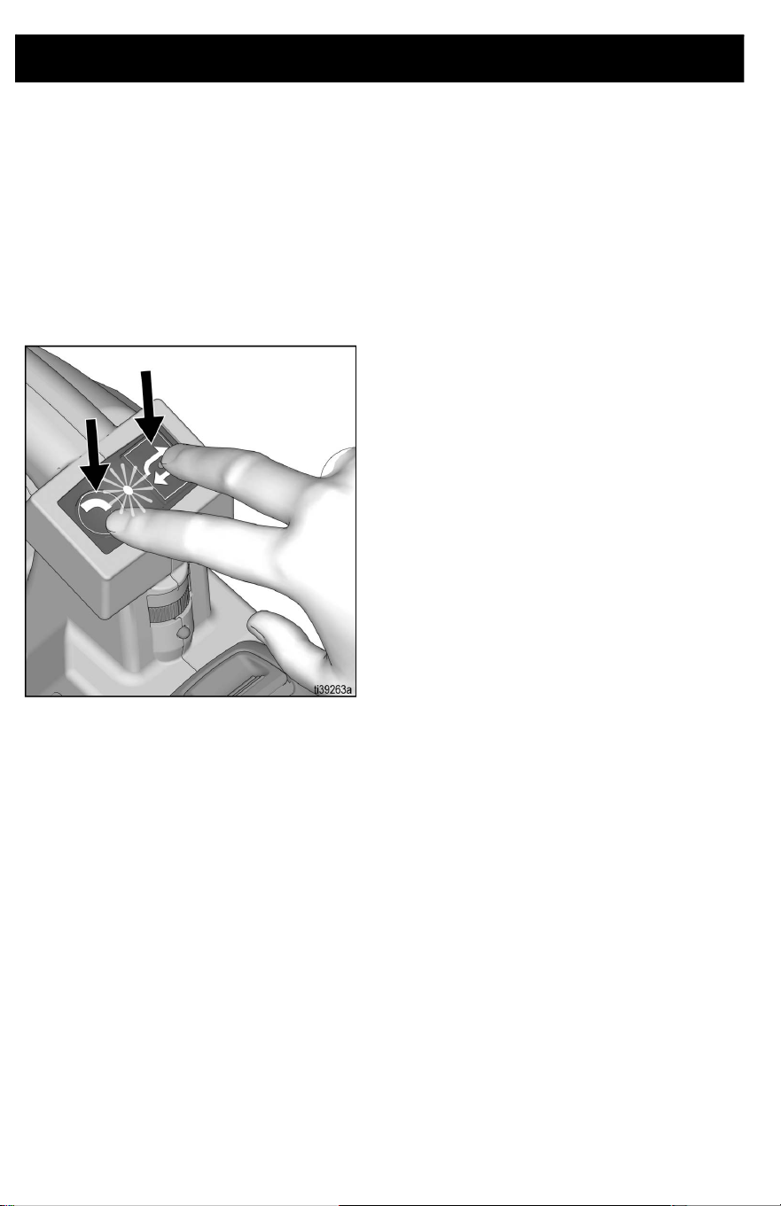
Continuous Run Mode
Continuous Run Mode is used for cleaning
purposes to flush or recirculate water, or to
transfer a large amount of material without
having to hold the button down the entire
time.
1. To make the unit continuously run, press
and hold both buttons simultaneously for
two seconds until the LED button begins
to blink.
2. Release the buttons and the unit will
continue to run until either button is
pressed again, or when the battery runs
out of power.
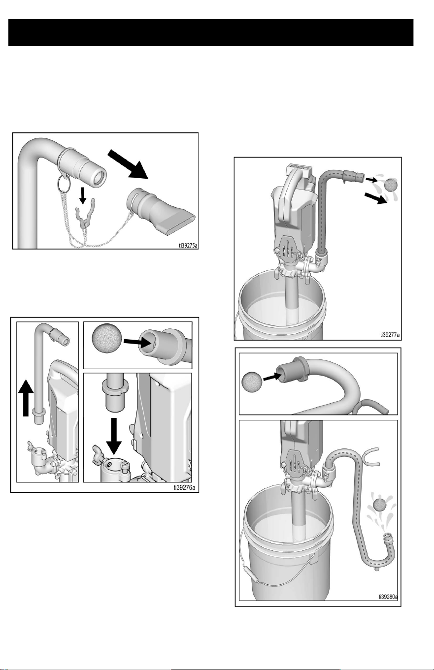
Cleaning
3A8110D 21
Cleaning
NOTE: Attach optional cleaning kit (P/N
18D167) and flush pump with water or
compatible cleaning agent to remove any
material or residue prior to removing any
parts.
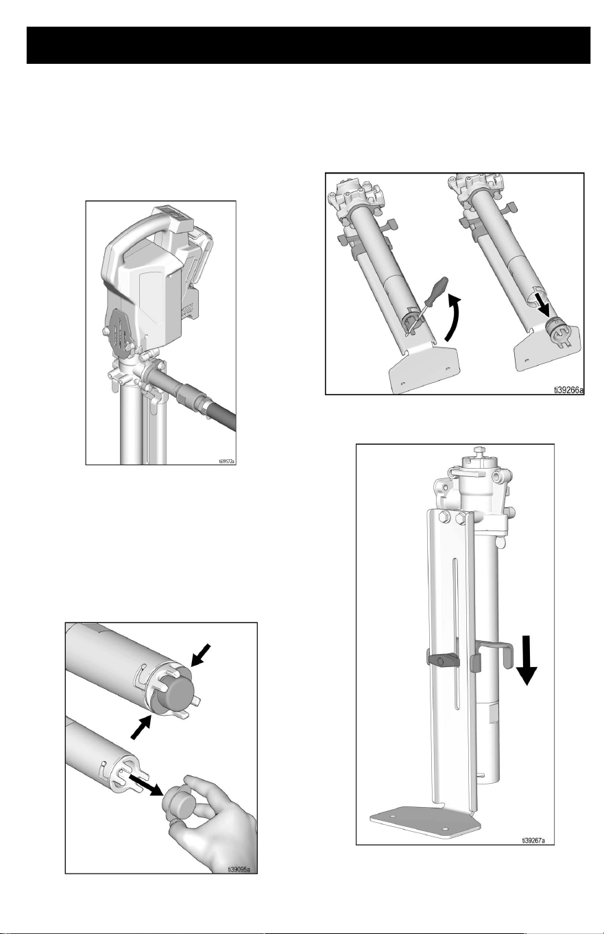
1. Remove Power Head, see Power Head
Removal, page 25.
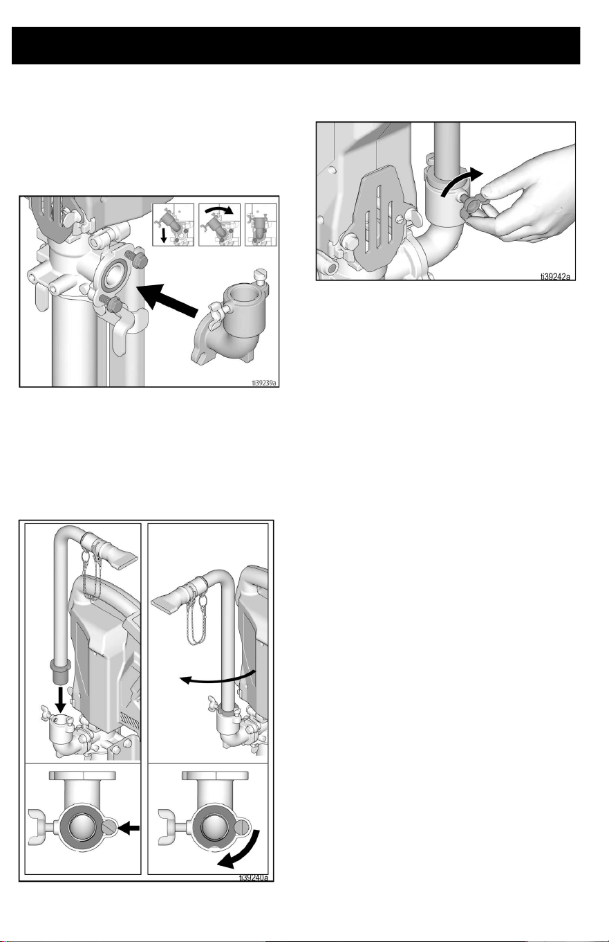
Pump Disassembly
2. Remove filter by pinching tabs on filter
and pulling. Rotate inlet housing and pull
to remove housing. Clean inlet assembly
in a bucket of water.
NOTE: If inlet housing is stuck, use a
screwdriver or rod for leverage to assist in
unscrewing the housing.
3. Lower the bucket stabilizer bracket.
Cleaning
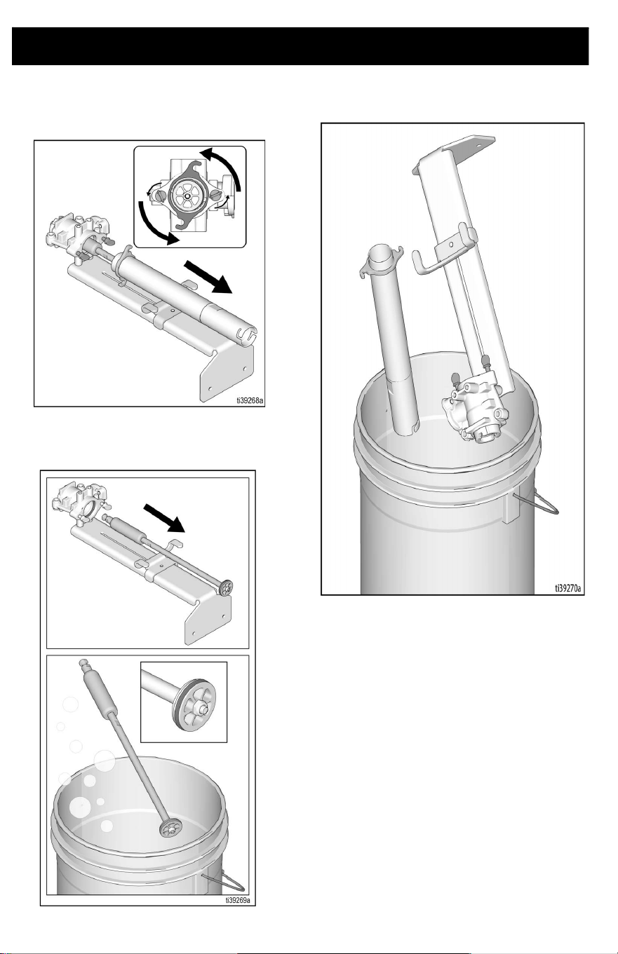
22 3A8110D
4. Loosen thumb screws at top of pump
and rotate pump cylinder 90 degrees.
Slide pump cylinder off of piston.
5. Remove piston and clean in a bucket of
water. Inspect seals for any damage and
replace if damaged.
6. Clean out inside of pump housing and
pump cylinder in bucket of water.
Cleaning
3A8110D 23
Pump Re-assembly
1. Carefully insert piston rod assembly into
pump housing. Be careful not to damage
the throat seal.
2. Slide cylinder onto piston, rotate onto
thumb screws. Hand tighten thumb
screws.
3. Re-assemble inlet housing and filter.
4. Re-assemble Power Head, see Power
Head Re-Assembly, page 26.
5. Apply Throat Seal Liquid (TSL) into
pump throat.
Cleaning
24 3A8110D
Cleaning Hi-Rise Filler Tube and Goose Neck
Attachments
1. Remove box filler attachment from the
Hi-Rise fill tube, if necessary.
2. Remove Hi-Rise fill tube or gooseneck
from the pro outlet and insert orange
cleaning ball into tube end and
reassemble to the outlet port.
3. Put pump in bucket of water or cleaning
solution and pump until the orange ball
moves through the tube, cleaning the
inside diameter.
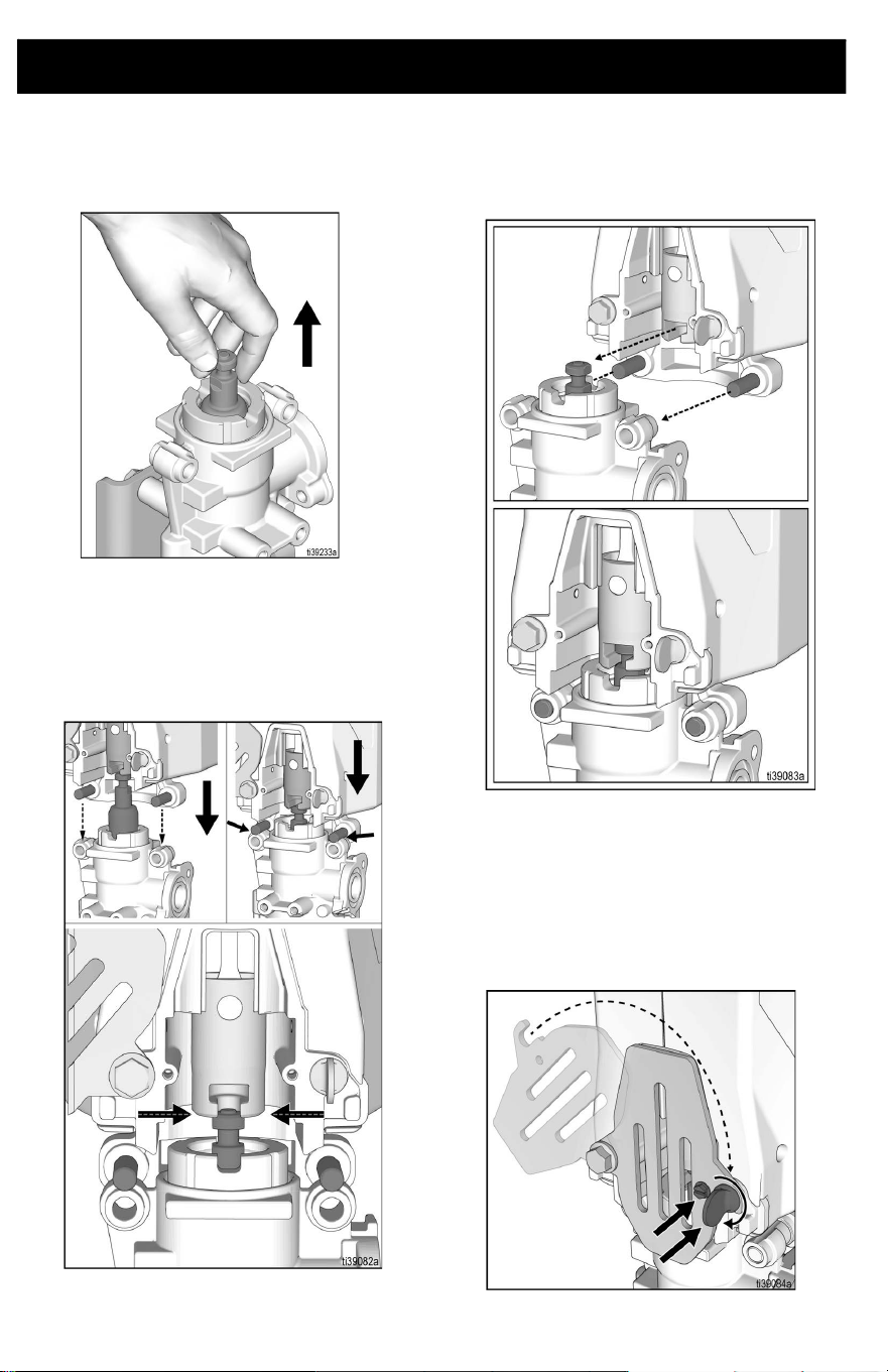
Pro Connect Removal and Assembly
3A8110D 25
Pro Connect Removal and Assembly
Power Head Removal
1. Set speed control to Setting 1 and jog
Power Head to position the piston and
slider in the bottom dead center position.
This step will make re-assembly easier.
2. Remove battery, see Battery
Installation and Removal, page 15.
3. Perform Pressure Relief Procedure,
page 17.
4. Remove locking screw and loosen
thumb screw. Rotate cover open.
5. Grab Power Head by motor vents and
pull the Power Head off the pump.
Support Power Head with two hands, if
necessary.
Pro Connect Removal and Assembly
26 3A8110D
Power Head Re-Assembly
1. If necessary, pull piston upwards so
slider will contact piston head.
2. Place slider on top of piston head.
3. Align piston head by slowly pressing
piston downward with the Power Head
until pins on Power Head rest atop the
pump frame.
4. Attach Power Head by inserting pins into
the proper holes on the pump. Power
Head should automatically align with
piston head once step 3 is complete.
NOTE: Ensure piston is properly inserted into
the Power Head prior to operation. Should
piston not align into the Power Head,
manually pull the piston up and re-align.
5. Close cover and tighten thumb screw to
secure Power Head. Ensure locking
screw is installed before operation.
Troubleshooting
3A8110D 27
Troubleshooting
1. Remove battery before repairing pump.
2. Check all possible problems and causes
before disassembling pump.
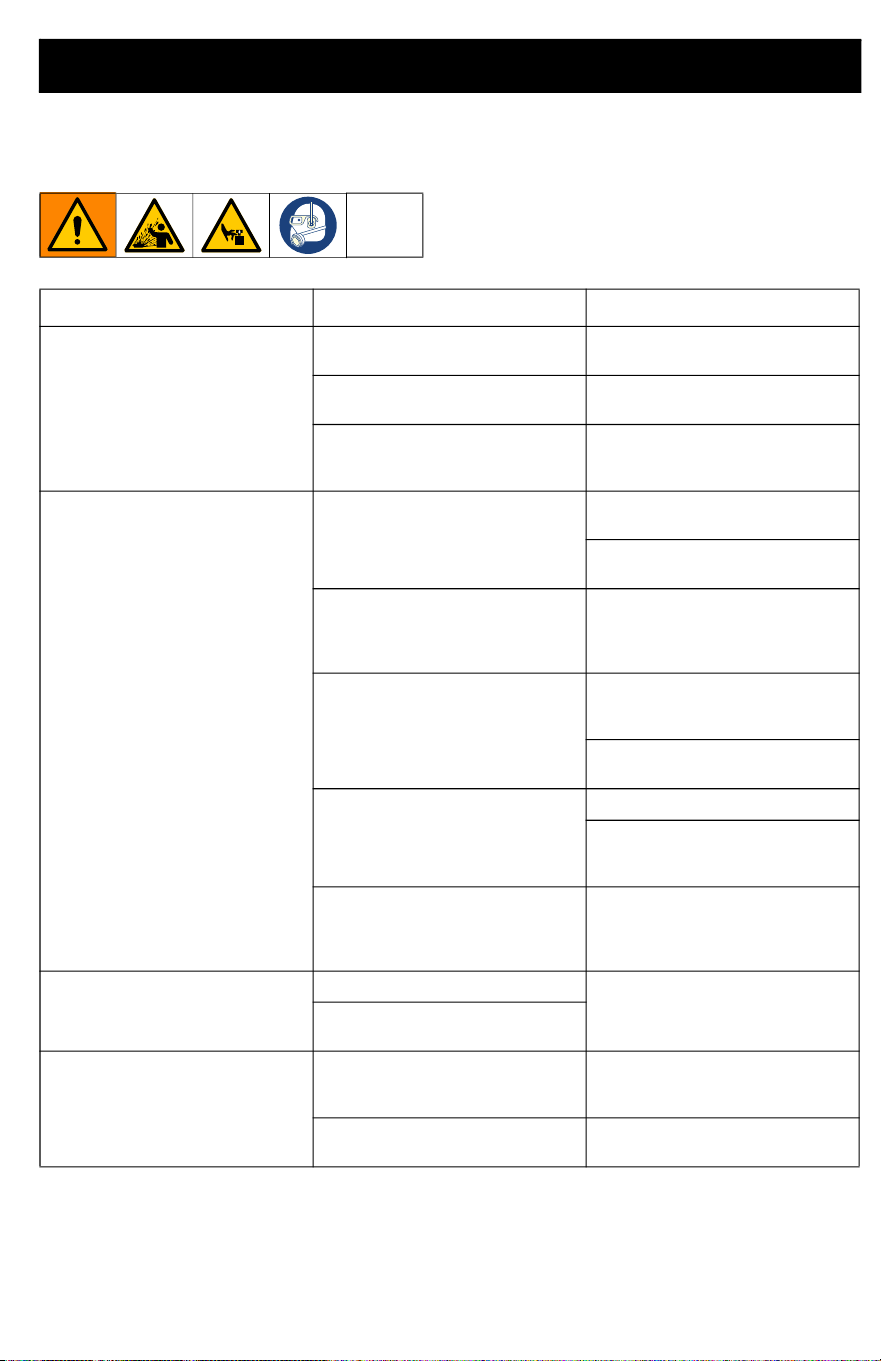
Problem Cause Solution
Unit stops running
Battery is not fully seated.
Re-insert battery, ensuring it is
fully seated.
Battery low on charge.
Replace battery with fully
charged one.
Plugged outlet tube.
Perform Pressure Relief
Procedure, page 17, and clear
all obstructions.
Equipment does not run
Diagnostic lights blinks two
times when dispensing button is
pushed. Indicates incorrect
voltage.
Replace battery with fully
charged one.
Battery has reached end of life.
Replace battery.
Diagnostic lights blinks three
times when dispensing button is
pushed. Indicates battery
temperature is too hot or cold.
Allow battery to cool down or
warm up to room temperature.
Diagnostic lights blinks four
times when dispensing button is
pushed. Indicates locked rotor
condition.
Perform Pressure Relief
Procedure, page 17, and clean
unit.
Replace pump assembly and/or
SmartControl Assembly.
Diagnostic light does not blink
dispensing button is pushed.
Indicates battery is not installed
or is damaged.
Install or replace battery.
Check switch functionality, see
Testing the Switch
Functionality, page 30.
Diagnostic light does not blink
when dispensing button is
pushed, and battery is
confirmed to be good.
Replace SmartControl
Assembly.
Leaking around pump rod
Failed throat seal.
Replace throat seal.
Throat seal installed upside
down.
Fluid delivery is slow
Speed control is set to low.
Increase pump speed by
increasing speed control. See,
Start Up, page 16.
Material is too thick.
Thin material or use a different
material.

Troubleshooting
28 3A8110D
Equipment runs with
intermittent flow
Inlet filter is clogged. Remove filter and clean.
Inlet valve is stuck open.
Remove and clean inlet to allow
for proper functionality
Inlet is not installed or loose.
Check inlet and ensure it is fully
installed.
Damaged inlet flapper valve.
Remove inlet and check flapper
valve for damage and replace if
necessary.
Faulty outlet flapper valve.
Remove cylinder or piston to
check piston flapper valve for
damage, or obstruction.
Too thick of material.
Thin material or use a different
material.
Equipment runs but no material
comes out
Pump is not primed.
Pour some water down outlet to
wet the seals.
Ensure pump is assembled
properly with throat seal, piston
seal, and inlet housing installed.
Piston isn't properly connected
to ProConnect.
Ensure piston is properly
assembled into slider, see Pro
Connect Removal and
Assembly, page 25.
Pump is starting to get worn out.
Inspect seals and replace if
necessary.
Material is too thick.
Thin material or use a different
material.
Material leaks around box filler
Internal o-ring failed or is
missing.
Install or replace if necessary.
Hard to install and remove
attachments to unit
O-rings dried out from joint
compound/pumping fluid.
Lubricate o-rings, see Box
Filler, page 13.
Power Head ProConnect won't
go together
Piston and slider and pins are
not properly aligned.
See ProConnect Operation, see
Pro Connect Removal and
Assembly, page 25.
Pins or mating holes have
contamination on them from
dried material.
Clean parts, lubricate, and
reassemble.
Pins or holes are bent.
Try to straighten out pins or
replace drive housing. See
Parts, page 32.
Problem Cause Solution
Troubleshooting
3A8110D 29
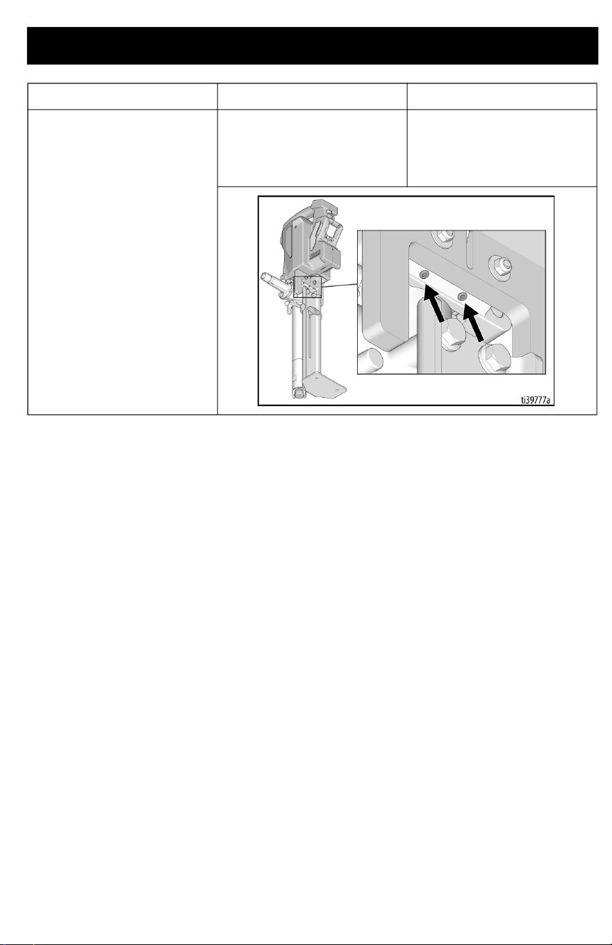
Power Head feels loose or rocks
on the pump
Set screws located on the
bottom of the Power Head may
have become loose (see image
below).
Tighten set screws carefully
until the rocking has been
removed (see image below).
Problem Cause Solution
Troubleshooting
30 3A8110D
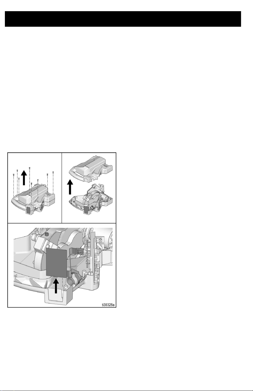
Testing the Switch Functionality
Follow the steps below to test your switch
functionality.
To Open Unit - All Units
1. Remove battery, see Battery
Installation and Removal, page 15.
2. Perform pressure relief procedure, see
Pressure Relief Procedure, page 17.
3. Turn unit on its side and remove ten
screws on clamshell.
4. Pull clamshell open and remove switch
from slot in the clamshell. Pull switch free
by disconnecting the connector on the
end of the ribbon.
5. Once open, follow testing procedure on
the following page.
Troubleshooting
3A8110D 31
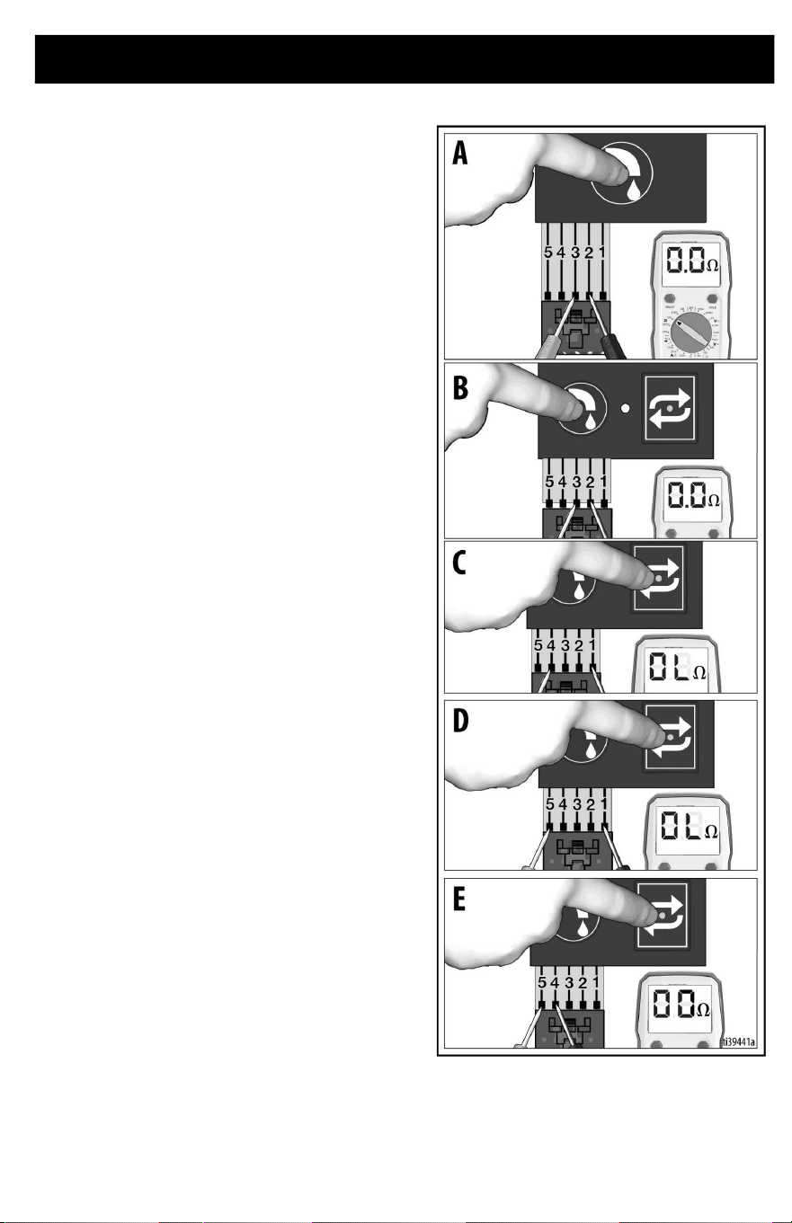
To Test Functionality - Standard Series
1. Using an Ohm meter, probe the ribbon
lines 2 and 3 and press the dispense
button. It should read ~0 ohms (Photo
A).
2. If Ohm meter does not read ~0 ohms
when pressing the dispense button,
replace the switch.
To Test Functionality - Pro Series
1. Using an Ohm meter, probe the ribbon
lines 2 and 3 and press the dispense
button. It should read ~0 ohms (Photo
B).
2. Probe ribbon lines 1 and 4 and press the
Repeat button. It should read OL or
MOhms (Photo C).
3. Probe ribbon lines 1 and 5 and press the
Repeat button. It should read OL or
MOhms (Photo D).
4. Probe ribbon lines 4 and 5 and press the
Repeat button. It should read ~0 ohms
(Photo E).
5. If Ohm meter does not read these
values, replace switch assembly.
Parts
32 3A8110D
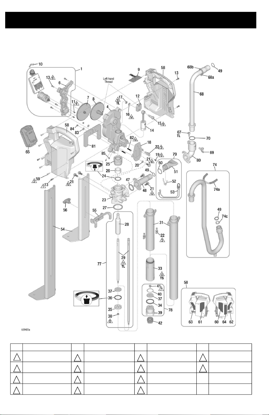
Parts
PowerFill 3.5 Standard, Pro, and XL Pro
Ref. Torque Ref. Torque Ref. Torque Ref. Torque
3 in-lbs. (0.34 N•m) 24 in-lbs (2.71 N•m) 375 in-lbs (42 N•m) 34 ft-lbs(46 N•m)
5 in-lbs (0.56 N•m) 30 in-lbs (3.4 N•m) 140 in-lbs (16 N•m)
100 in-lbs (11.3 N•m)
10 in-lbs (1.13 N•m) 40 in-lbs (4.5 N•m) 15 ft-lbs (20 N•m) TS Thread Sealant
20 in-lbs (2.26 N•m) 80 in-lbs (9 N•m) 18 ft-lbs (24 N•m) TL
Medium Strength
Thread lock
1
5 9
13
2
6
10 14
3 7
11
4 8
12

Parts
3A8110D 33
PowerFill 3.5 Standard, Pro, and XL Pro Parts List
2
Ref. Part Description Qty.
1 18F104 KIT, assembly, motor/smart
control, includes 6, 13
1
4 18F110 HOUSING, drive,
sub-assembly, includes 18,
19. 20, 21, 22, 81, 82, 83, 84
1
6 HOUSING, motor, machined 1
7 18F107 KIT, gear, stage one,
sub-assembly
1
8 18F108 KIT, gear, stage two,
sub-assembly
1
9 SWITCH, board 1
18F300 Standard Models 26B417,
26B435, 26B536, 26B439,
26B442, 26B432
18F301 Pro Models 26B418, 26B419,
26B436, 26B437, 26B537,
26B538, 26B440, 26B441,
26B443, 26B444, 26B433,
26B434, 26B472, 26B473
10 17D843 SIGHTGLASS 1
11 16G740 SCREW, SHCS 3
12 19B807 CRANK, drive, output 1
13 133174 SCREW, cap, socket head 8
14 18F109 KIT, rod, connection,
sub-assembly
1
15 125027 SCREW, shoulder, socket
head, M8
1
16 133103 WASHER, lock, external
tooth, M8
1
17 133104 NUT, hex, thin, M8 x 1.25 1
18 19B810 COVER, pro connect, 2 PIN 1
19 116431 SCREW, mach, hex wash hd. 1
20 133096 SPACER 1
21 118241 SCREW, cap, flange, hex hd. 5
22 132981 SCREW, thumb 5/16-18 UNC 3
23 19B798 HOUSING, pump, machined 1
24 † 18C888 SEAL, throat 1
25 18F102 NUT, packing, includes 26 1
26 WIPER, fiber, pump rod 1
27 * 133100 PACKING, O-ring, BUNA-N,
-327, 70 DUR
1
28 18F099 ROD, throat, piston 1
29 ROD, piston, extension 1
18C886 Models 26B417, 26B418,
26B435, 26B436, 26B536,
26B537, 26B439, 26B440,
26B442, 26B443, 26B432,
26B433, 26B472
18C898 Models 26B419, 26B437,
26B538, 26B441, 26B444,
26B434, 26B473
31 CYLINDER, pump, upper 1
18F105 Models 26B417, 26B418,
26B435, 26B436, 26B536,
26B537, 26B439, 26B440,
26B442, 26B443, 26B432,
26B433, 26B472
18F106 Models 26B419, 26B437,
26B538, 26B441, 26B444,
26B434, 26B473
33 18F098 CYLINDER, lower 1
34 * 133017 O-RING, square 1
35 18C891 PISTON, seal housing 1
36 † 18C890 SEAL, piston 1
37 † 18C889 VALVE, check flap 2
38 133098 NUT, lock, 1/4-28 UNF 1
39 19B946 HOUSING, inlet, assembly 1
40 * 120818 PACKING, O-ring 1
41 133079 SCREW, mach, hex, washer
hd.
1
42 18D170 FILTER, inlet 1
47 * 133116 O-RING, packing, 321,
BUNA-N
1
48 19B800 ADAPTER, outlet, standard,
machined
1
49 * 155332 PACKING, O-ring 1
50 * 121110 PACKING, O-ring, BUNA-N,
122
1
51 19B953 ADAPTER, fill, box tool 1
52 133080 CLIP, retainer 1
53 18F096 CHAIN, ring, lanyard 1
54 BRACKET, foot 1
18C876 Models 26B417, 26B418,
26B435, 26B436, 26B536,
26B537, 26B439, 26B440,
26B442, 26B443, 26B432,
26B433, 26B472
18C900 Models 26B419, 26B437,
26B538, 26B441, 26B444,
26B434, 26B473
55 18C880 BRACKET, stabilizer 1
56 18C883 KNOB, tee, 5/16-18 x 3/8 1
58 KIT, clamshell, includes 60,
61, 62, 63, 64
1
18F111 Standard Models 26B417,
26B435, 26B536, 26B439,
26B442, 26B432
18F112 Pro Models 26B418, 26B419,
26B436, 26B437, 26B537,
26B538, 26B440, 26B441,
26B443, 26B444, 26B433,
26B434, 26B472, 26B473
59 119236 SCREW, machine, torx, pan
head
8
60 18D095 LABEL, brand, Graco, right 1
61 18D096 LABEL, brand, Graco, left 1
62 LABEL, brand, right 1
18D145 Models 26B417, 26B435,
26B536, 26B439, 26B442,
26B432
18D097 Models 26B418, 26B419,
26B436, 26B437, 26B537,
26B538, 26B440, 26B441,
26B443, 26B444, 26B433,
26B434, 26B472, 26B473
63 LABEL, brand, left 1
18D144 Models 26B417, 26B435,
26B536, 26B439, 26B442,
26B432
18D098 Models 26B418, 26B419,
26B436, 26B437, 26B537,
26B538, 26B440, 26B441,
26B443, 26B444, 26B433,
26B434, 26B472, 26B473
64 ▲ LABEL, safety, warning 1
18D148 Models 26B417, 26B418,
26B419
20A539 Models 26B432, 26B433,
26B434
20A538 Models 26B435, 26B436,
26B437, 26B536, 26B537,
26B538
20A540 Models 26B439, 26B440,
26B441, 26B442, 26B443,
26B444, 26B472, 26B473
Ref. Part Description Qty.

Parts
34 3A8110D
65 BATTERY, serial, DEWALT,
20V
1
17P474 Models 26B417, 26B418,
26B419
17P556 Models 26B432, 26B433,
26B434
17P557 Models 26B435, 26B439,
26B536, 26B436, 26B440,
26B537, 26B437, 26B441,
26B538
17P558 Models 26B442, 26B443,
26B444
17Y586 Models 26B472, 26B473
66 CHARGER, DEWALT, 20V 1
17P475 Models 26B417, 26B418,
26B419
17P559 Models 26B432, 26B433,
26B434
17P560 Models 26B435, 26B439,
26B536, 26B436, 26B440,
26B537, 26B437, 26B441,
26B538
17P561 Models 26B442, 26B443,
26B444
17Y587 Models 26B472, 26B473
67 19B947 SCREW, clamping, adapter 1
68 TUBE, fill, includes 68a, 68b 1
18D099 14 in.
18D100 23 in.
68a RING, retainer 1
68b RING, retaining 1
69 133129 SCREW, wing 5/16-18 1
70 154662 O-RING 1
74 KIT, goose neck assembly,
complete
1
18D161 Models 26B417, 26B435,
26B536, 26B439, 26B442,
26B432, includes 80, 67, 69,
70, 74a, 74c, 49, 21, 47
18D086 Models 26B418. 26B436,
26B537, 26B440, 26B443,
26B433, 26B472
18D103 Models 26B419, 26B437,
26B538, 26B441, 26B444,
26B434, 26B473
74a 133147 CAP, round, vinyl 2
74c 18E112 SPACER, tube, gooseneck 1
77 KIT, piston, assembly,
includes 28, 29, 35, 36, 37,
38, 24
1
18F100 Models 26B417, 26B418,
26B435, 26B436, 26B536,
26B537, 26B439, 26B440,
26B442, 26B443, 26B432,
26B433, 26B472
18F101 Models 26B419, 26B437,
26B538, 26B441, 26B444,
26B434, 26B473
78 18F097 KIT, repair, inlet assembly,
includes 34, 37, 39, 40, 41
1
79 18D169 KIT, assembly, box filler,
includes 50, 51, 52, 53
1
80 19B799 ADAPTER, outlet 1
81 18E128 LEG, Powerfill 3.5 1
82 133298 SCREW, cap, socket hd. 2
83 112776 WASHER, plain 2
84 115483 NUT, lock 2
* Included in 18F116, Complete O-Ring kit
† Included in 18F103, Pump seal kit
▲Replacement safety labels, tags, and cards are available at
no cost.
Ref. Part Description Qty.

Technical Specifications
3A8110D 35
Technical Specifications
U.S. Metric
Max Working Pressure 125 psi 0.86 MPa, 8.6bar
PowerFill 3.5 Standard Dimensions, without outlet (with outlet)
Length 11.5 in. (11.5 in.) 29.2 cm (29.2 cm)
Width
6.2 in. (12 in.) 15.8 cm (30.5 cm)
Height
31.1 in. (31.1 in.) 79 cm (79 cm)
Weight 15 lb. 6.8 kg
PowerFill 3.5 Pro Dimensions, without outlet (with outlet)
Length 11.5 in. (11.5 in.) 29.2 cm (29.2 cm)
Width
6.2 in. (14.7 in.) 15.8 cm (37.4 cm)
Height
31.1 in. (34.3 in.) 79 cm (87.2 cm)
Weight 17 lb. 7.7 kg
PowerFill 3.5 XL Pro Dimensions, without outlet (with outlet)
Length 11.5 in. (11.5 in.) 29.2 cm (29.2 cm)
Width
6.2 in. (14.7 in.) 15.8 cm (37.4 cm)
Height
44 in. (47.2 in.) 111.8 cm (119.9 cm)
Weight 20 lb. 9.1 kg
Storage Temperature Range ◆❊ 32° to 113° F 0° to 45° C
Operating Temperature Range 40° to 90° F 4° to 32° C
Storage Humidity Range 0% to 95% relative humidity, non-condensing
Sound Pressure Level
80 dBa
Sound Power Level † 97.5 dBa
Uncertainty K = 3 dBa
Charger Power Source
26B417, 26B418, 26B419, 26B432,
26B433, 26B434
100 – 120 Vac, 60 Hz, 15A, 1 Ø
26B435, 26B436, 26B437, 26B536,
26B537, 26B538, 26B439, 26B440,
26B441, 26B442, 26B443, 26B444
230 Vac, 50 Hz, 16A, 1 Ø
Battery
Voltage (DC) 18 V and 20 V MAX* 2.0 Ahr Li-ion Compact Battery Pack
DEWALT
Materials of Construction
Wetted materials on all models Aluminum, stainless steel, Buna-N, and polyurethane
Notes
◆ Pump damage can occur if material or water freezes in pump.
❊ Damage to plastic parts may result if impact occurs in low temperature conditions.
† All readings were taken in priming mode at the assured operator position. Sound power levels were
tested to ISO 3741 at 3.3 feet (1m).
* Maximum initial Battery voltage (measured without a workload) is 20 volts. Nominal voltage is 18.

Recycling and Disposal
36 3A8110D
Recycling and Disposal
End of Product Life
At the end of the product’s useful life,
dismantle and recycle it in a responsible
manner.
• Perform the Pressure Relief
Procedure, page 17.
• Drain and dispose of fluids according to
applicable regulations. Refer to the
material manufacturer’s Safety Data
Sheet.
• Remove motors, batteries, circuit
boards, and other electronic
components. Recycle according to
applicable regulations.
• Do not dispose of electronic components
with household or commercial waste.
• Deliver remaining product to a recycling
facility.
California Proposition 65
CALIFORNIA RESIDENTS
WARNING: Cancer and reproductive harm –
www.P65warnings.ca.gov.

Graco Standard Warranty
3A8110D 37
Graco Standard Warranty
Graco warrants all equipment referenced in this document which is manufactured by Graco and bearing
its name to be free from defects in material and workmanship on the date of sale to the original purchaser
for use. With the exception of any special, extended, or limited warranty published by Graco, Graco will,
for a period of twelve months from the date of sale, repair or replace any part of the equipment
determined by Graco to be defective. This warranty applies only when the equipment is installed,
operated and maintained in accordance with Graco’s written recommendations.
This warranty does not cover, and Graco shall not be liable for general wear and tear, or any malfunction,
damage or wear caused by faulty installation, misapplication, abrasion, corrosion, inadequate or
improper maintenance, negligence, accident, tampering, or substitution of non-Graco component parts.
Nor shall Graco be liable for malfunction, damage or wear caused by the incompatibility of Graco
equipment with structures, accessories, equipment or materials not supplied by Graco, or the improper
design, manufacture, installation, operation or maintenance of structures, accessories, equipment or
materials not supplied by Graco.
This warranty is conditioned upon the prepaid return of the equipment claimed to be defective to an
authorized Graco distributor for verification of the claimed defect. If the claimed defect is verified, Graco
will repair or replace free of charge any defective parts. The equipment will be returned to the original
purchaser transportation prepaid. If inspection of the equipment does not disclose any defect in material
or workmanship, repairs will be made at a reasonable charge, which charges may include the costs of
parts, labor, and transportation.
THIS WARRANTY IS EXCLUSIVE, AND IS IN LIEU OF ANY OTHER WARRANTIES, EXPRESS OR
IMPLIED, INCLUDING BUT NOT LIMITED TO WARRANTY OF MERCHANTABILITY OR WARRANTY
OF FITNESS FOR A PARTICULAR PURPOSE.
Graco’s sole obligation and buyer’s sole remedy for any breach of warranty shall be as set forth above.
The buyer agrees that no other remedy (including, but not limited to, incidental or consequential damages
for lost profits, lost sales, injury to person or property, or any other incidental or consequential loss) shall
be available. Any action for breach of warranty must be brought within two (2) years of the date of sale.
GRACO MAKES NO WARRANTY, AND DISCLAIMS ALL IMPLIED WARRANTIES OF
MERCHANTABILITY AND FITNESS FOR A PARTICULAR PURPOSE, IN CONNECTION WITH
ACCESSORIES, EQUIPMENT, MATERIALS OR COMPONENTS SOLD BUT NOT MANUFACTURED
BY GRACO. These items sold, but not manufactured by Graco (such as electric motors, switches, hose,
etc.), are subject to the warranty, if any, of their manufacturer. Graco will provide purchaser with
reasonable assistance in making any claim for breach of these warranties.
In no event will Graco be liable for indirect, incidental, special or consequential damages resulting from
Graco supplying equipment hereunder, or the furnishing, performance, or use of any products or other
goods sold hereto, whether due to a breach of contract, breach of warranty, the negligence of Graco, or
otherwise.
FOR GRACO CANADA CUSTOMERS
The Parties acknowledge that they have required that the present document, as well as all documents,
notices and legal proceedings entered into, given or instituted pursuant hereto or relating directly or
indirectly hereto, be drawn up in English. Les parties reconnaissent avoir convenu que la rédaction du
présente document sera en Anglais, ainsi que tous documents, avis et procédures judiciaires exécutés,
donnés ou intentés, à la suite de ou en rapport, directement ou indirectement, avec les procédures
concernées.

Graco Information
38 3A8110D
Graco Information
For the latest information about Graco products, visit www.graco.com.
For patent information, see www.graco.com/patents.
TO PLACE AN ORDER, contact your Graco distributor or call 1-800-690-2894 to identify the
nearest distributor.

Graco Information
3A8110D 39

All written and visual data contained in this document reflects the latest product information available at
the time of publication. Graco reserves the right to make changes at any time without notice.
Original instructions. This manual contains English. MM3A8110
Graco Headquarters: Minneapolis
International Offices: Belgium, China, Japan, Korea
GRACO INC. AND SUBSIDIARIES • P.O. BOX 1441 • MINNEAPOLIS MN 55440-1441 • USA
Copyright 2021, Graco Inc. All Graco manufacturing locations are registered to ISO 9001.
www.graco.com
Revision D, January 2023