©2023 Hestan Commercial Corporation
1
EN
OUTDOOR LIVING
SUITE
(WITH CUSTOMER-PROVIDED STONE TOPS)
INSTALLATION INSTRUCTIONS
IMPORTANT - READ ALL INSTRUCTIONS BEFORE YOU BEGIN
THE INSTALLATION HEREIN SHOULD BE PERFORMED BY A QUALIFIED SERVICE TECHNICIAN
OR PROFESSIONAL OUTDOOR EQUIPMENT INSTALLER. MANY COMPONENTS ARE HEAVY AND
REQUIRE 2 OR 3 PERSONS TO UN-PACK AND SETUP THIS SUITE. FAILURE TO DO SO MAY RESULT
IN PERSONAL INJURY.
THE ELECTRICAL COMPONENTS SUPPLIED WITH THIS SUITE MUST BE INSTALLED BY A
LICENSED ELECTRICIAN AND CONNECTED IN ACCORDANCE WITH LOCAL CODES. THE SUITE
SHOULD BE CONNECTED TO A DEDICATED CIRCUIT BREAKER. ALL OUTLETS SUPPLIED WITH
THIS SUITE ARE GROUND FAULT CIRCUIT INTERRUPTER OUTLETS AND MUST BE PROPERLY
INSTALLED AND GROUNDED BY A LICENSED ELECTRICIAN TO GUARANTEE SAFE AND RELIABLE
OPERATION.
SOME PARTS INSIDE THE SUITE HAVE SHARP EDGES. CARE MUST BE TAKEN WHEN HANDLING
THE VARIOUS COMPONENTS TO AVOID PERSONAL INJURY. WEAR GLOVES WHEN HANDLING.
TOOLS REQUIRED:
Work gloves
Safety glasses
Power drill with masonry bits
Concrete / masonry anchors or hardware as needed to attach to mounting surface
Flat and Phillips screwdrivers
Socket wrench with 7/16” & 9/16” sockets and short extensions
Combination wrenches of 7/16” & 9/16” sizes
3/32 Allen wrench
Level
Clear silicone sealant
IF THE INFORMATION IN THE GAS-FIRED APPLIANCE MANUALS
ARE NOT FOLLOWED EXACTLY, A FIRE OR EXPLOSION MAY RESULT
CAUSING PROPERTY DAMAGE, PERSONAL INJURY, OR DEATH.
Flammable Gas - disconnect all propane or natural gas supplies to this unit
before servicing.
Electrical Parts and Components – disconnect all power supplies and
batteries before servicing.
AFTER INSTALLATION OF YOUR GRILL AND OTHER GAS-FIRED EQUIPMENT IN THIS
SUITE, READ THE MANUAL(S) PROVIDED WITH THOSE PRODUCTS CAREFULLY AND
COMPLETELY BEFORE USING THEM TO REDUCE THE RISK OF FIRE, BURN HAZARD,
OR OTHER INJURY. KEEP THIS MANUAL FOR FUTURE REFERENCE.
GES08 GES12 GESP12 GESK12 GESC12
GESB08 GESB12 GESBP12 GESBK12 GESBC12
©2023 Hestan Commercial Corporation
2
EN
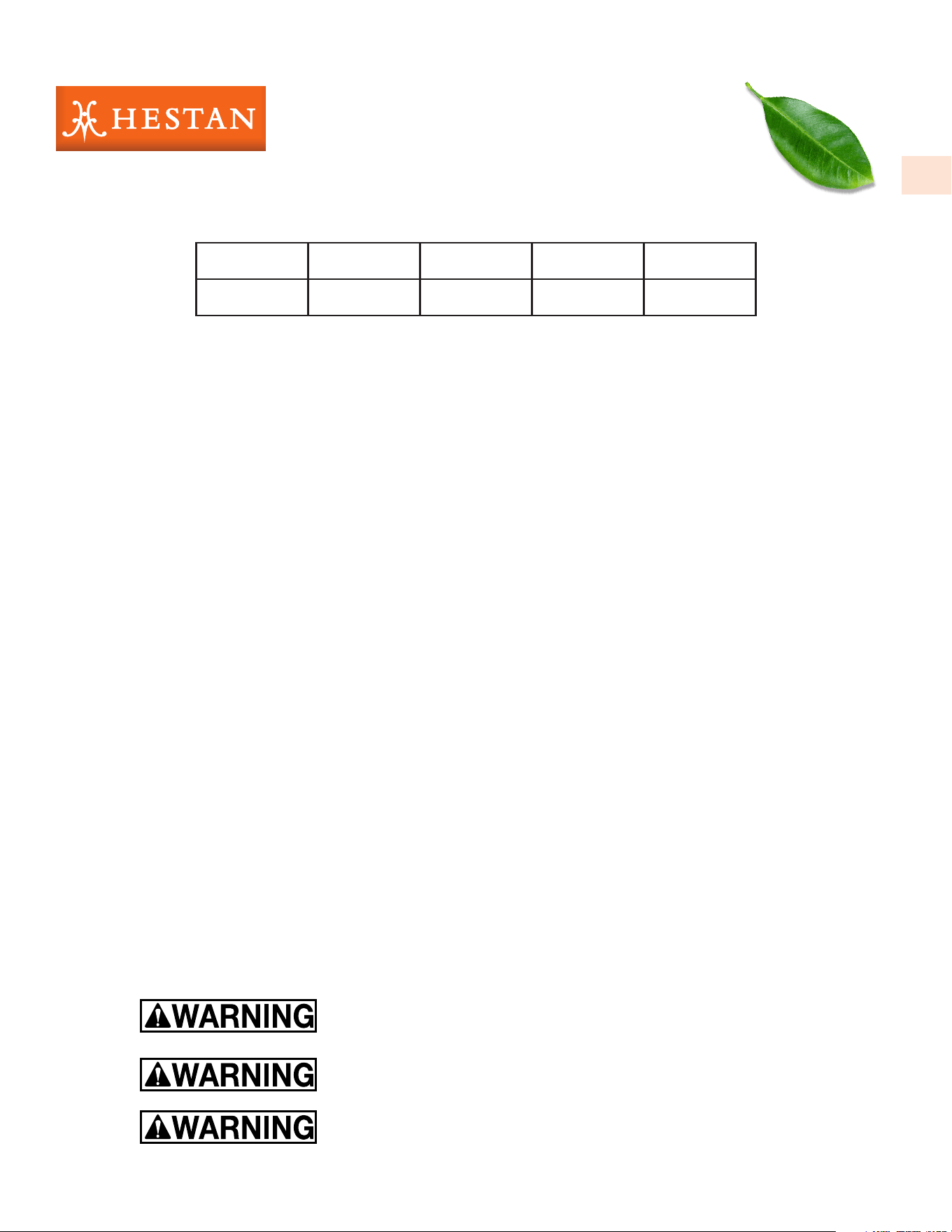
SUITE MODELS WITH CUSTOMER-PROVIDED TOP
Suite GES08 shown with:
GABR36 Built-In Gas Grill
AGB122 Double Side Burner
AGSDR36 Combo Door/Drawer Cabinet
GRSR24 Outdoor Solid Door Refrigerator
ALL ITEMS PURCHASED SEPARATELY
STONE TOP NOT INCLUDED
Below are representations of some Hestan Outdoor Living Suites covered in this manual.
Suite GESB12 shown with:
GABR42 Built-In Gas Grill
AGB122 Double Side Burner
AGTC Trash Chute
AGSDR42 Combo Door/Drawer Cabinet
AGDR16 Double Drawers
AGTRC20 Trash & Recycling Center
GFDSR241 Outdoor Single Faucet Beer Dispenser
ALL ITEMS PURCHASED SEPARATELY
STONE TOPS NOT INCLUDED
MODEL # DESCRIPTION
GES08 GRILL, OUTDOOR LIVING SUITE, CUSTOMER-PROVIDED COUNTERTOP, 8 FOOT
GESB08 GRILL, OUTDOOR LIVING SUITE, CUSTOMER-PROVIDED COUNTERTOP & BAR, 8 FOOT
GES12 GRILL, OUTDOOR LIVING SUITE, CUSTOMER-PROVIDED COUNTERTOP, 12 FOOT
GESB12 GRILL, OUTDOOR LIVING SUITE, CUSTOMER-PROVIDED COUNTERTOP & BAR, 12 FOOT
GESP12 GRILL, OUTDOOR LIVING SUITE, CUSTOMER-PROVIDED COUNTERTOP, POWER BURNER, 12 FOOT
GESBP12 GRILL, OUTDOOR LIVING SUITE, CUSTOMER-PROVIDED COUNTERTOP & BAR, POWER BURNER, 12 FOOT
GESK12 GRILL, OUTDOOR LIVING SUITE, CUSTOMER-PROVIDED COUNTERTOP, KAMADO, 12 FOOT
GESBK12 GRILL, OUTDOOR LIVING SUITE, CUSTOMER-PROVIDED COUNTERTOP & BAR, KAMADO, 12 FOOT
GESC12 GRILL, OUTDOOR LIVING SUITE, CUSTOMER-PROVIDED COUNTERTOP, PIZZA OVEN, 12 FOOT
GESBC12 GRILL, OUTDOOR LIVING SUITE, CUSTOMER-PROVIDED COUNTERTOP & BAR, PIZZA OVEN, 12 FOOT
HESTAN OUTDOOR LIVING SUITES
©2023 Hestan Commercial Corporation
3
EN
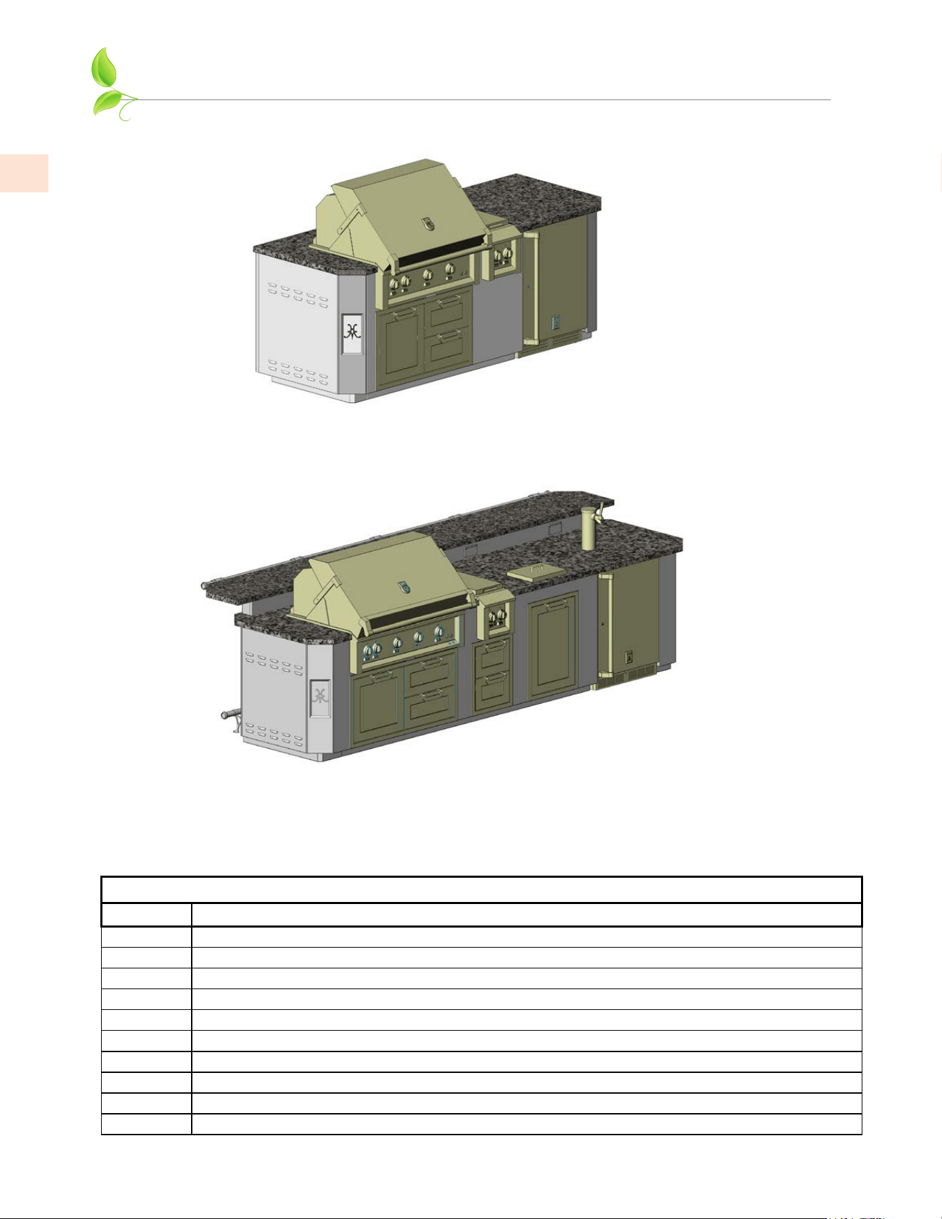
The Hestan Outdoor Living suite features ventilation openings (louvers) on each end. These
openings must be clear to avoid accumulation of gas should there be a leak. These openings are
further described later in this manual.
Figure 1
LOCATING THE SUITE
LOCATIONLOCATION
When determining a suitable location for your grill and suite, take into account concerns such as exposure to
wind, rain, sprinklers, proximity to traffic paths, and keeping any gas supply line runs as short as possible.
Locate the grill only in a well-ventilated area. Never locate the grill in a building, garage, or other such
enclosed areas. Never locate the grill over, under, or next to unprotected combustible construction. Further
definitions of these areas, combustible vs. non-combustible construction, etc. can be found in the manual(s)
accompanying the individual appliances.
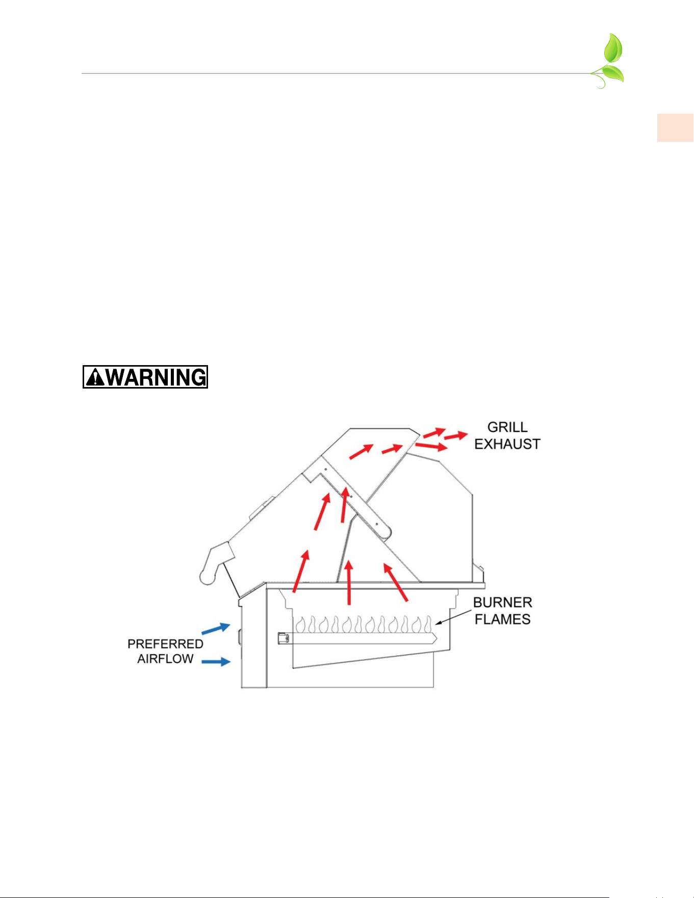
AIRFLOW / WINDY AREASAIRFLOW / WINDY AREAS
During heavy use, the grill will produce a lot of heat and smoke. The grill is designed to take in cool air at the
front control panel area, and send the combustion products and smoke out the exhaust gap at the rear of the
hood. IT IS IMPORTANT TO MAINTAIN THIS FLOW AT ALL TIMES.
Using the grill in windy areas can disrupt the proper airflow and cause damage to your grill, or result in burn
hazards to the user. Initial indications of this situation are very hot control knobs. Using an oven mitt or
other protection, and while keeping your face away, immediately open the hood to release the built up heat
inside the grill. Turn down the burners to a lower setting. It is very important that the suite and grill is
oriented so the prevailing wind is toward the front of the grill as seen below in Fig. 1.
For built-in grill installations which consistently receive wind at the rear of the grill, a Wind Screen accessory
is available from Hestan. Contact your Hestan dealer for details.
Damage caused from use in windy conditions, such as melted knobs
and/or wiring, discoloration of the control panel, etc., is excluded from
warranty coverage.
©2023 Hestan Commercial Corporation
4
EN
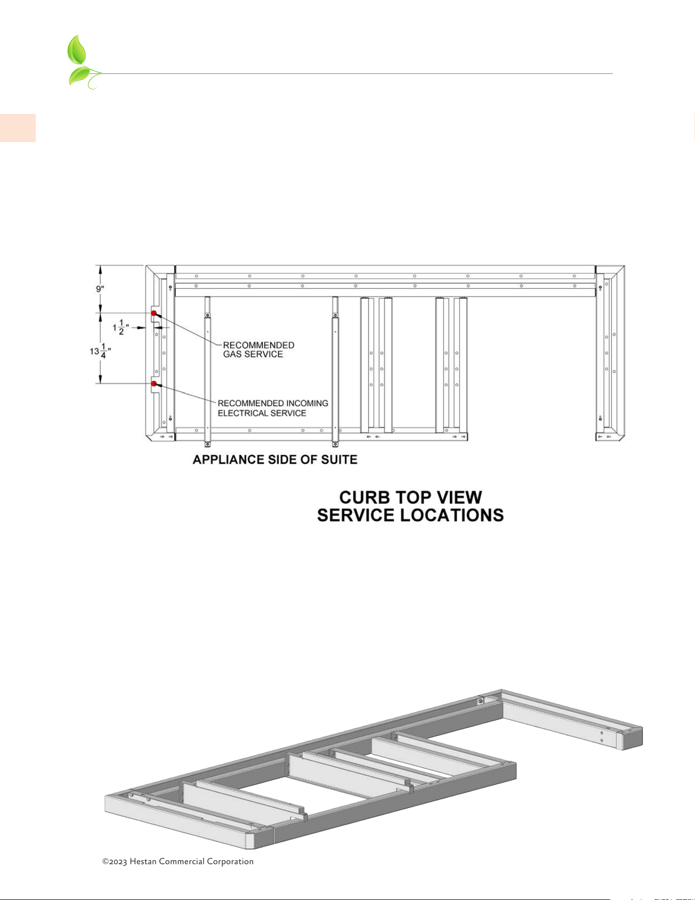
2. The curb should be as level as possible and permanently anchored to the mounting surface using
stainless steel masonry anchors and bolts, or other fasteners as appropriate (not included). If you
choose not to permanently anchor your suite, be sure you have moved it to its final location. Also
be aware that the suites featuring a bar are prone to tipping over unless the curb is anchored to the
floor surface.
If you intend to tile around the curb base, take into consideration the footrails provided with suites
featuring a bar. See pg. 18 for more details.
The Outdoor Living Suite is very heavy and difficult to move once assembly is complete and all
equipment has been installed. (8 foot Outdoor Living Suite curb shown)
CURB INSTALLATION AND SERVICE LINES
1. The Hestan Outdoor Living Suite must be located on a flat and level mounting surface, not on
direct soil. The mounting surface must be capable of handling the weights of all the equipment
including the suite, countertop materials, installed appliances and cabinets, refrigeration
equipment, etc. This could be as much as 2400 lbs. [1088 kg] of equipment. The contractor /
architect responsible for the design of this mounting surface must also take into account other
items such as furniture, people, snow loads in winter, etc., in accordance with local codes.
A licensed plumber and electrician should run their service lines to the suite area prior
to installation of the curb, in accordance with local codes. See dimensions below for
recommended location. See ELECTRICAL ITEMS section of this manual for further details.
The gas line to the suite will require a shut-off that is easily accessible. Local codes may also
require a tracer wire be buried alongside the gas line for underground detection. See the GAS
CONNECTIONS section of this manual, and the appliance manual(s) for more details.
©2023 Hestan Commercial Corporation
5
EN
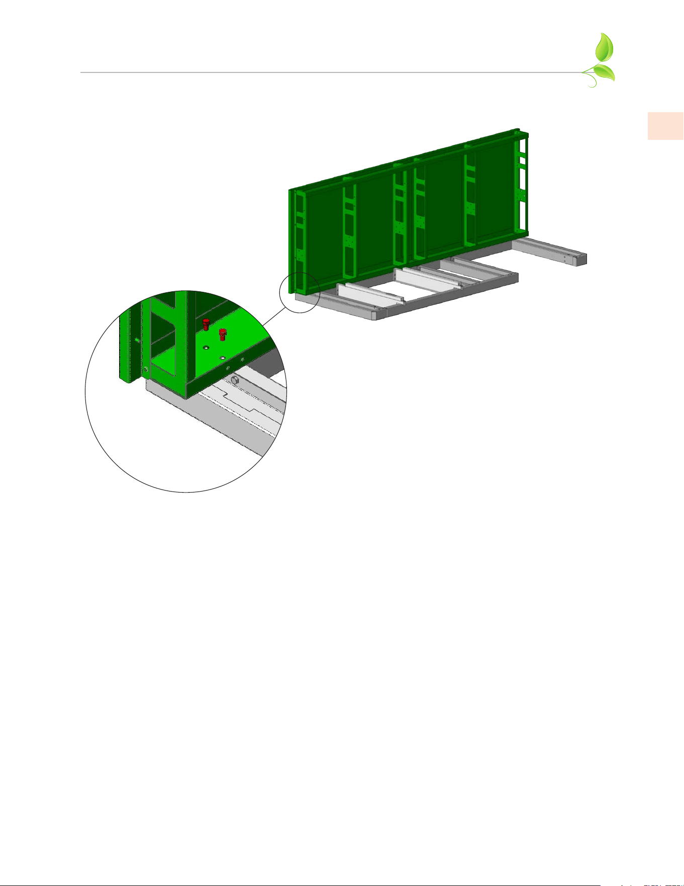
BACK AND SUPPORT WALL ASSEMBLY
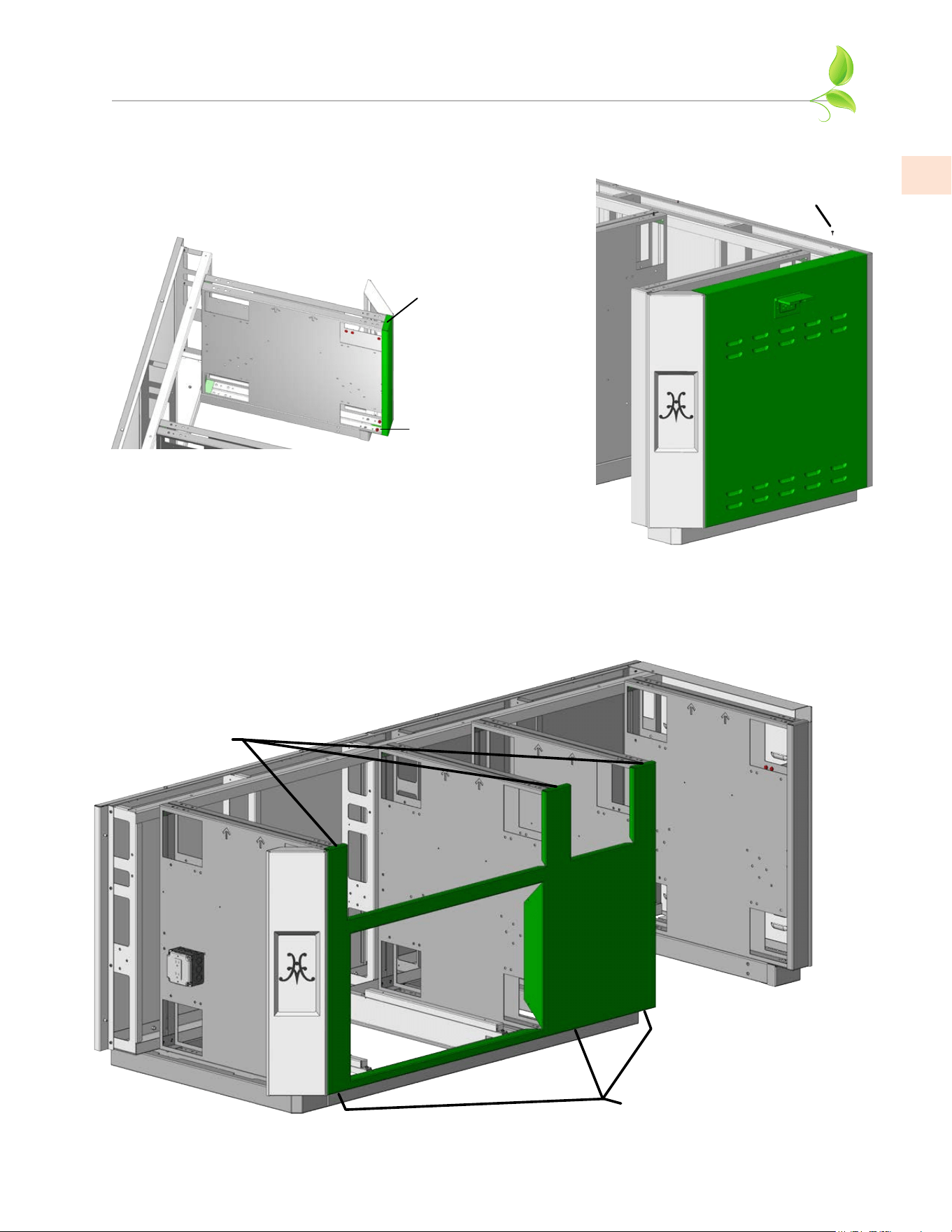
3. Use 4 each 3/8-16 x 5/8” long hex bolts to align and attach the back wall to the curb. Be careful the
back wall does not tip over if the curb was not anchored down. Tighten all bolts.
©2023 Hestan Commercial Corporation
6
EN
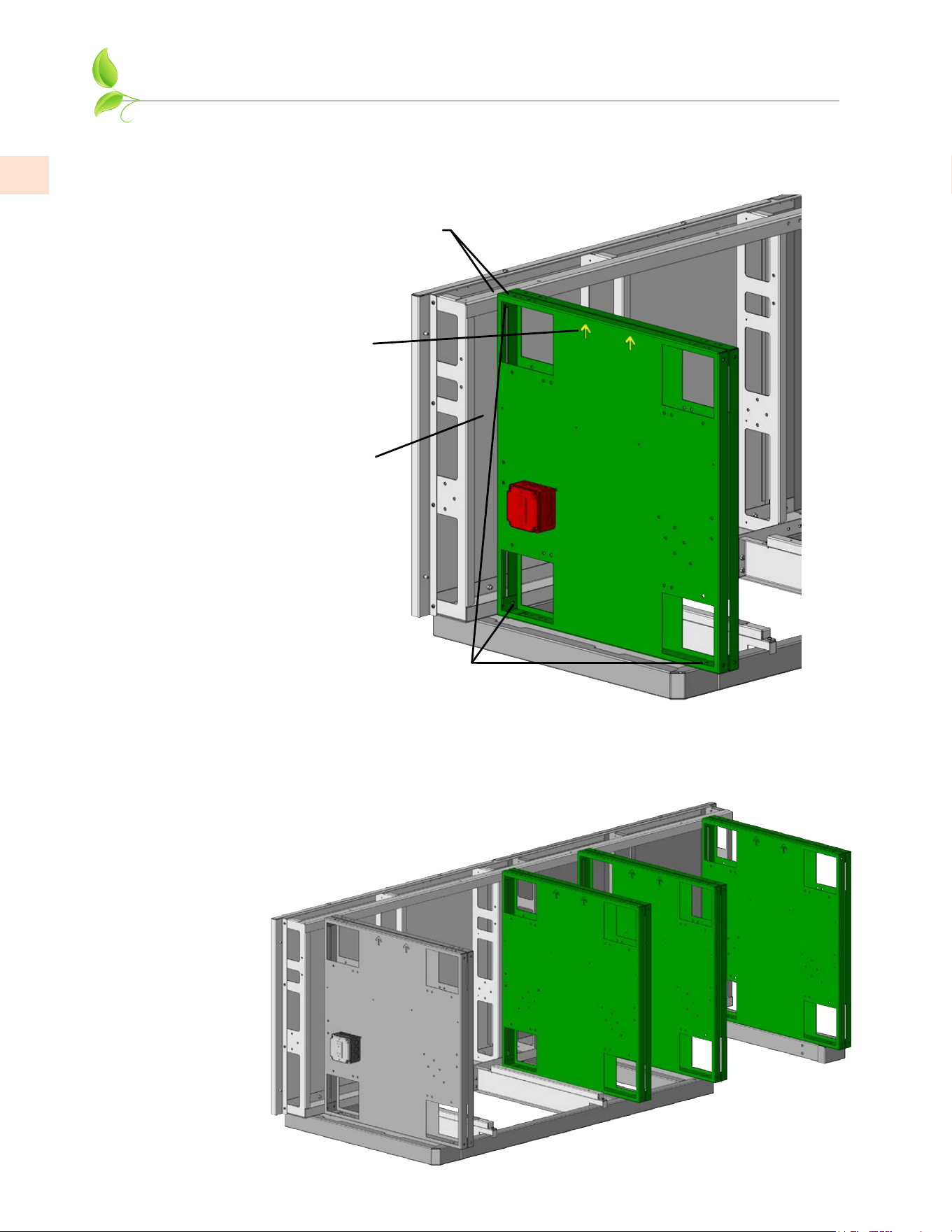
BACK AND SUPPORT WALL ASSEMBLY
(continued)
1/4-20 x 1/2” BOLTS
& NUTS HERE
MAIN ELECTRICAL BOX
ROUTE THIS BOX
BETWEEN THIS SPACE.
ATTACH TO THIS WALL USING
2 STUDS AT REAR OF BOX.
ARROWS
POINTING UP
NUMBERING
PRINTED ON
TOP FACES
4. Each support wall is numbered at the factory on the top faces. Attach support wall #1 to curb
assembly and back wall at location #1 as shown using 6 each 1/4-20 x 1/2” hex bolts and hex nuts
where needed. Do not fully tighten bolts yet. Route the main electrical box as described below and
attach using 2 each 1/4” hex nuts.
5. Install remaining support walls as you did in step 4. Each wall is numbered and has a corresponding
number on the rear wall for ease of locating. (8 foot Outdoor Living Suite shown)
Do not fully tighten bolts yet. Note all arrows are pointing up.
©2023 Hestan Commercial Corporation
7
EN
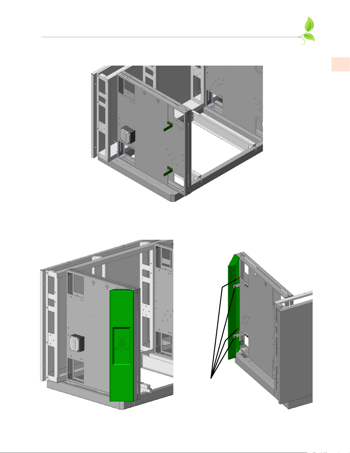
INSTALL CORNER ASSEMBLY
6. Install corner assembly brackets as shown using 1/4-20 x 1/2” long hex bolts and hex nuts where
needed. For suites with Bar Top, install 4 brackets on each side.
7. Install 2 corner assemblies (4 assemblies for suites with Bar Top). Use 1/4-20 x 1/2” long hex bolts
and hex nuts where needed. Do not tighten until lift-off panels have been checked for proper t
(see Step 13).
1/4-20 x 1/2” BOLTS
& NUTS HERE

©2023 Hestan Commercial Corporation
8
EN
ELECTRICAL ITEMS
ELECTRICAL BOXES AND CONDUIT
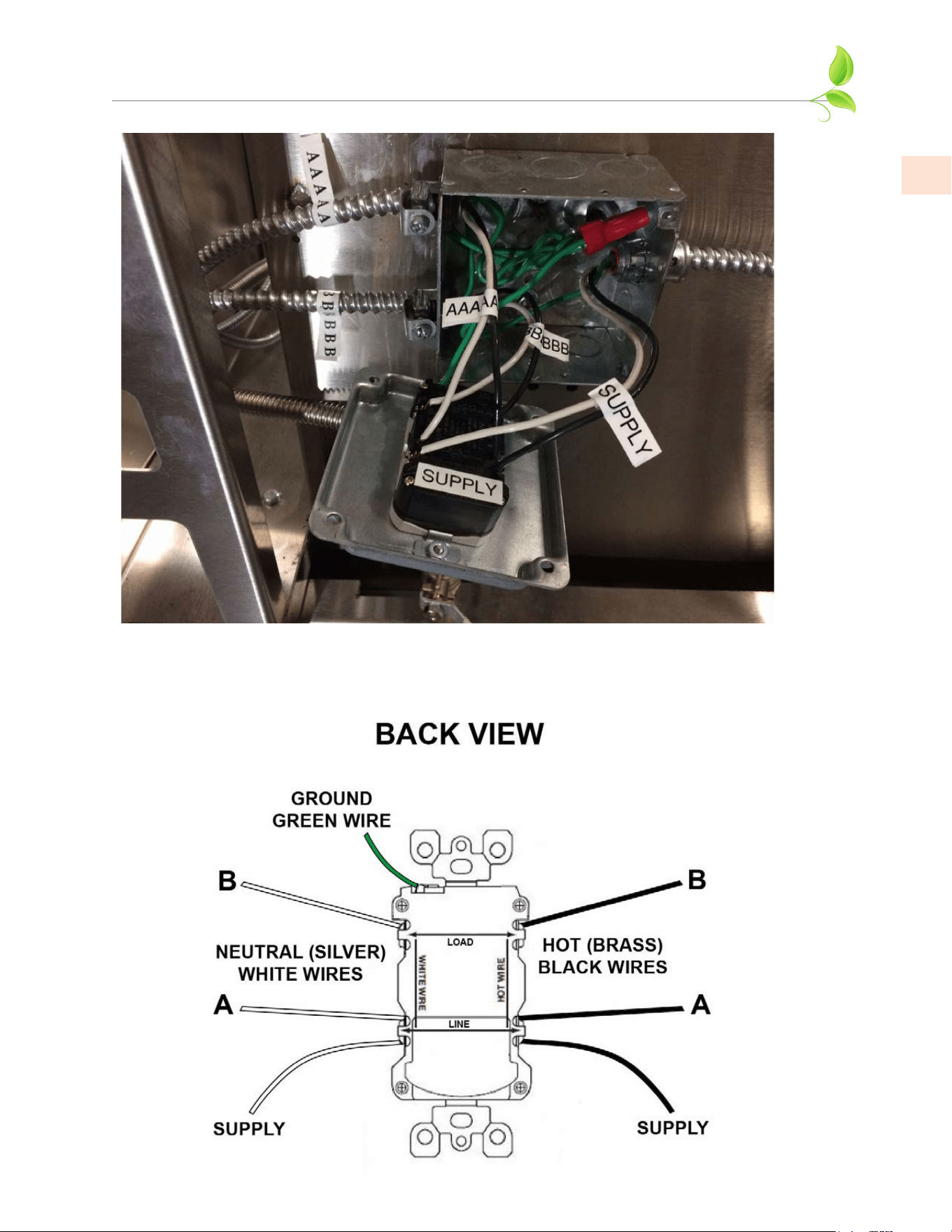
8. As mentioned in Step 1, a licensed electrician must run the electrical supply lines from the house
main electrical panel (20 amp breaker), to the recommended area below the curb base. This supply
is brought into the main electrical box as shown in the photo on the next page. The flex conduits
coming out of this box are labeled “A” or “B”. The electrician will make up the final connections as
shown in the diagrams on the following pages.
This main electrical box contains a GFCI outlet, which protects all the “B” outlets. The “A” circuit
runs to the weather-proof GFCI outlet located on the right side of the Suite, or to the outlets at the
bar (for those models featuring a raised bar). Should the GFCI trip due to a fault at the Grill, Side
Burner, or Refrigerator (“B” outlets), it must be reset, and the other “A” outlets will not be affected.
Similarly, the “A” GFCI will not affect the “B” outlets if it trips due to a fault.
ELECTRICAL SUPPLY
The Hestan Outdoor Living Suite is completely pre-wired for ease of installation. The suite will
require a 20 amp supply (breaker) from the house main electrical panel. The licensed electrician
will have to run the appropriate wire size and conduit for this application. Rigid or flexible
conduit suitable for burial with water-tight connections are highly recommended from the house
main electrical panel, to the suite.
Important: The appliance(s) must be electrically grounded in accordance with local codes, or in
the absence of local codes with the National Electrical Code,
ANSI/NFPA 70-1990
.
Appliances (grill, side burner, refrigerators, etc. ) are equipped with a flexible electrical supply
cord featuring a three-prong grounding plug. It is imperative that this plug be connected to a
properly grounded three-prong receptacle. If the receptacle is not the proper grounding type,
contact an electrician. Do not remove the grounding prong from this plug.
The appliances are designed for 120 volt AC power and must be plugged into a Ground Fault
Circuit Interrupter (GFCI) protected circuit. For gas-burning appliances, do not connect to
the electrical supply until after gas connections have been made and leak checks have been
performed.
KEEP ANY ELECTRICAL CORDS AND FUEL SUPPLY HOSES AWAY FROM ANY HEATED KEEP ANY ELECTRICAL CORDS AND FUEL SUPPLY HOSES AWAY FROM ANY HEATED
SURFACES.SURFACES.
• To protect against electric shock, do not immerse cord or plugs in water or other liquid.
• Unplug from the outlet when not in use and before cleaning. Allow to cool before putting
on or taking off parts.
• Do not operate any outdoor cooking gas appliance with a damaged cord or plug, or after the
appliance malfunctions or has been damaged in any manner. Contact the manufacturer for
repair.
• Do not let the cord hang over the edge of a table or touch hot surfaces.
• Do not use an outdoor cooking gas appliance for purposes other than intended.
• Use only a Ground Fault Circuit Interrupter (GFCI) protected circuit with this outdoor
cooking gas appliance.
• Never remove the grounding prong or use with a 2-prong ground adapter.
• Use only extension cords with a 3-prong grounding plug, rated for the power of the
equipment, and approved for outdoor use with a W-A marking.
©2023 Hestan Commercial Corporation
9
EN
MAIN ELECTRICAL BOX SHOWING SUPPLY
LINE ENTERING ON RIGHT SIDE OF BOX.
ELECTRICAL ITEMS
(continued)
©2023 Hestan Commercial Corporation
10
EN
ELECTRICAL ITEMS
(continued)
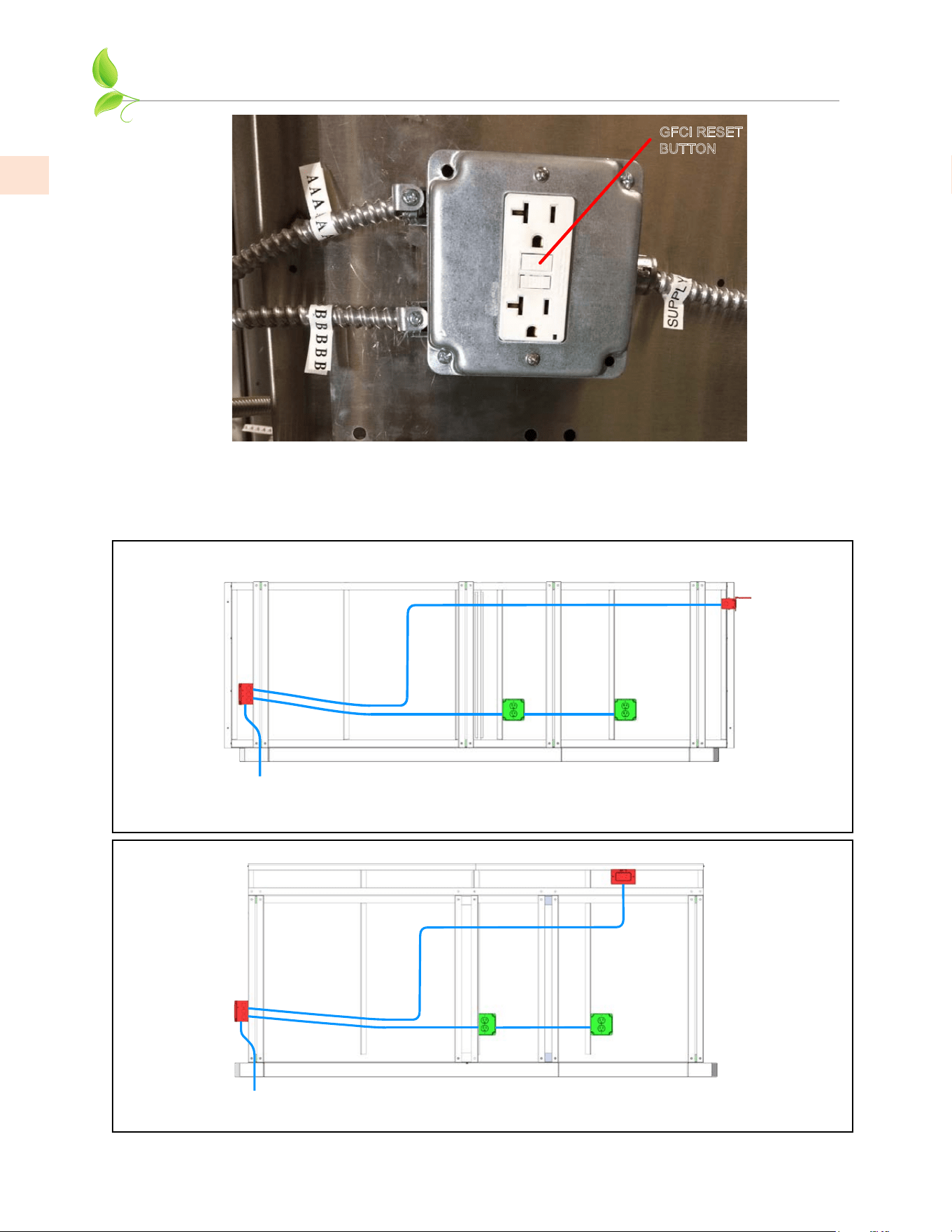
MAIN ELECTRICAL BOX
WITH GFCI OUTLET
GFCI
OUTLET
OUTLET
OUTLET
SERVICE
LINE IN
8 FOOT SUITE WITHOUT BAR
GESS08, GESD08, GES08
A
A
A
A
B
B
B
MAIN ELECTRICAL BOX
WITH GFCI OUTLET
SERVICE
LINE IN
A
B
GFCI
OUTLET
OUTLET
OUTLET
A
A
B
B
8 FOOT SUITE WITH BAR
GESSB08, GESDB08, GESB08
A
GFCI RESET
BUTTON
MAIN ELECTRICAL BOX COMPLETE
©2023 Hestan Commercial Corporation
11
EN
ELECTRICAL ITEMS
(continued)
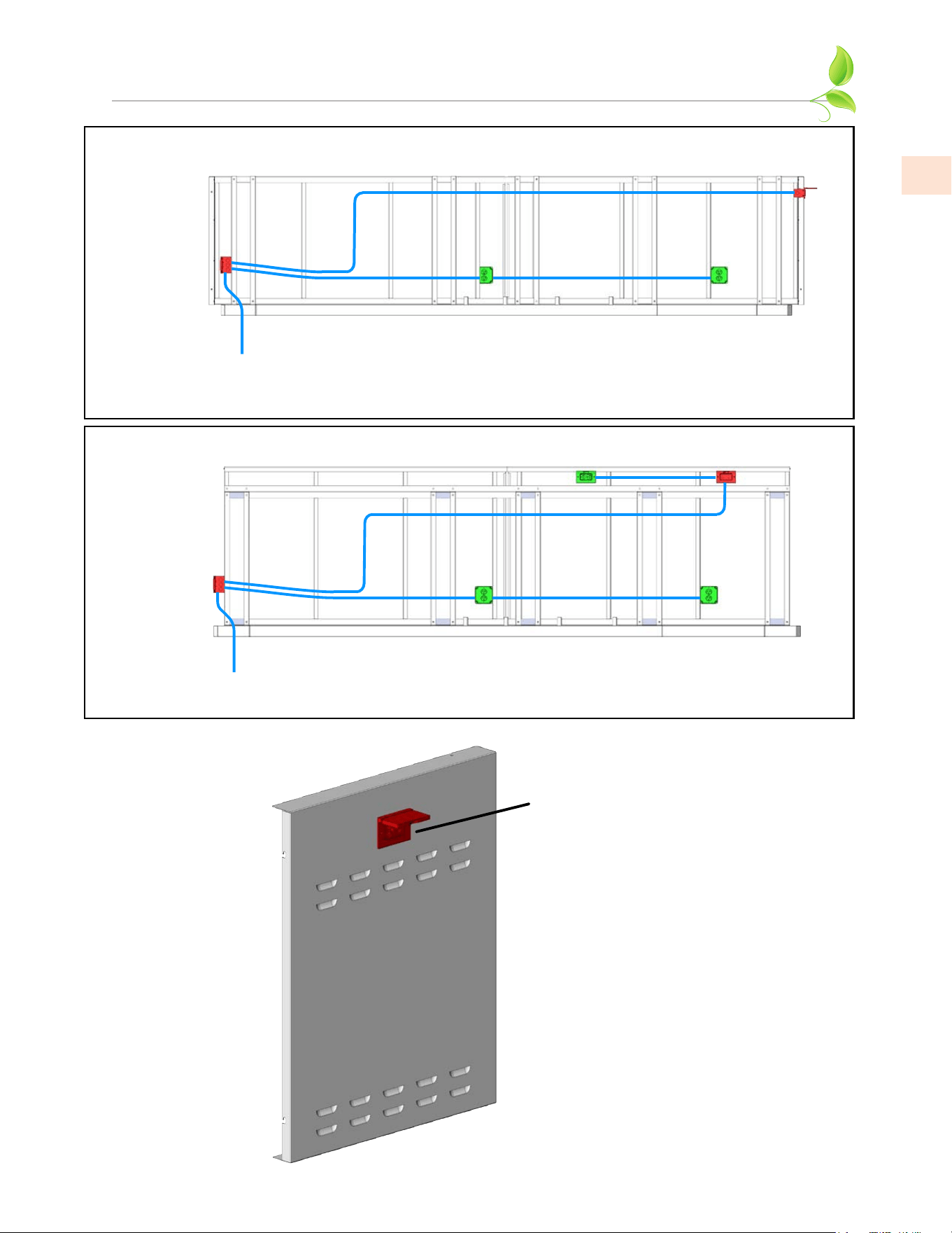
MAIN ELECTRICAL BOX
WITH GFCI OUTLET
GFCI
OUTLET
OUTLET
OUTLET
SERVICE
LINE IN
12 FOOT SUITE WITHOUT BAR
GESS12, GESD12, GES12
A
A
B
B B
A
A
MAIN ELECTRICAL BOX
WITH GFCI OUTLET
GFCI
OUTLET
OUTLET
OUTLET
OUTLET
SERVICE
LINE IN
12 FOOT SUITE WITH BAR
GESSB12, GESDB12, GESB12
A
B
A
A
A
B
B
A
RIGHT SIDE OF SUITE
(For Suite without Bar)
GFCI OUTLET WITH
WEATHERPROOF COVER
©2023 Hestan Commercial Corporation
12
EN
INSTALL OUTER PANELS
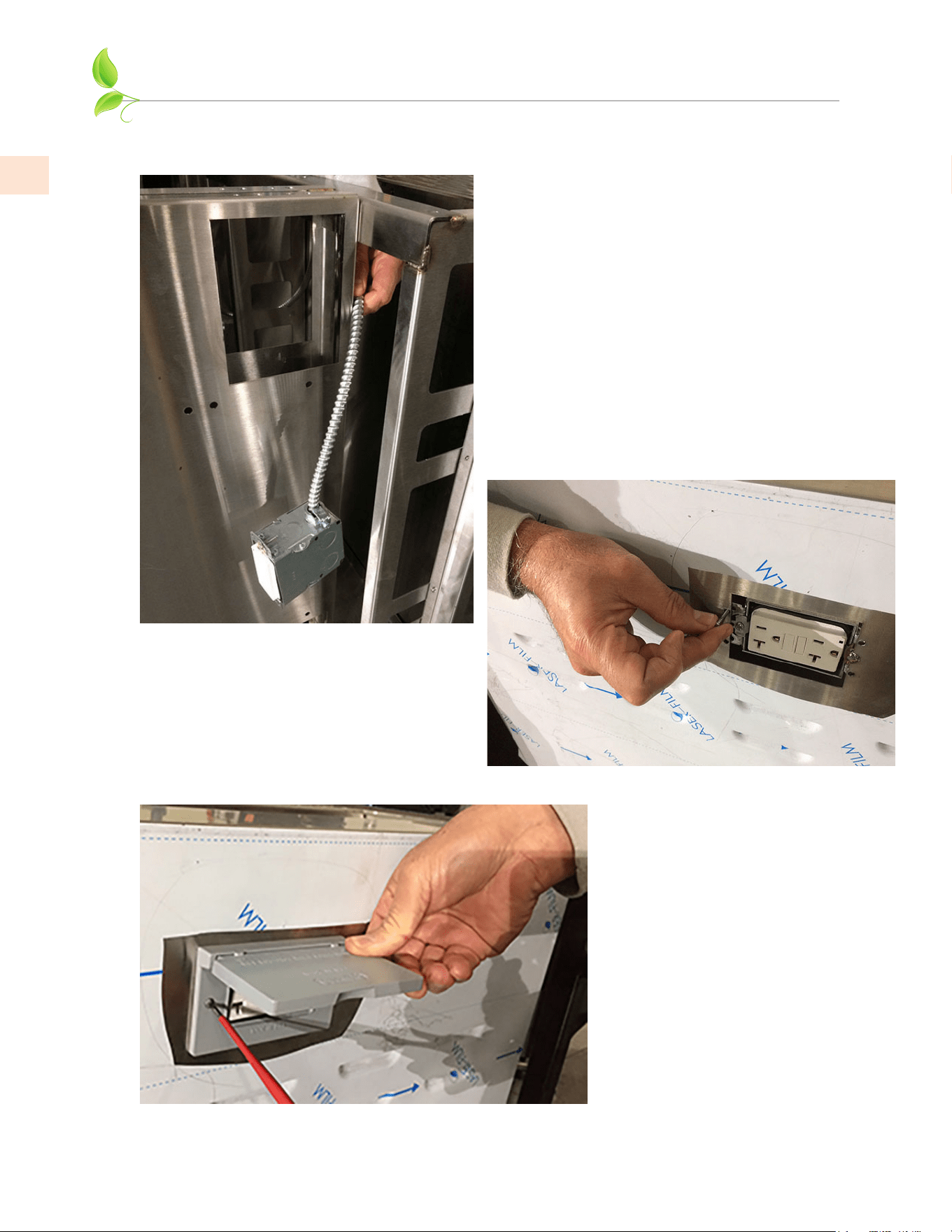
9. The GFCI outlet on the right side of the suite is shipped loosely and must be passed through the
space shown below and installed from behind the right panel (does not apply to Suite with a bar).
Line up and install 4 each #10
screws as shown here.
Install the foam gasket, and
weather-proof cover with the
screws provided.
©2023 Hestan Commercial Corporation
13
EN
INSTALL OUTER PANELS
(continued)
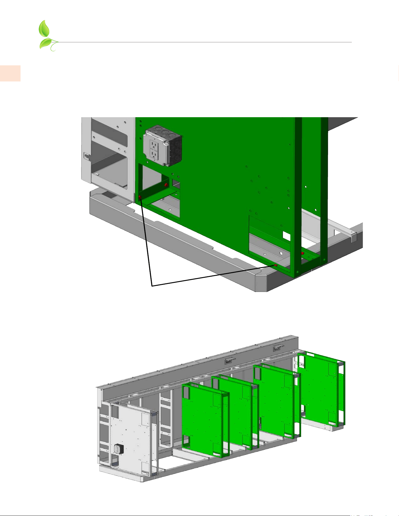
10. Install small front panel as shown using 2 each 1/4-20 x 1/2” long hex bolts and hex nuts, and 1 each
#8-32 flat-head screws across the top flange. With wiring complete, secure right panel as shown
with a #10 self-drilling screw.
1/4-20 x 1/2” BOLTS
& NUTS HERE
#8-32 FLAT-HEAD
SCREWS ACROSS
TOP FLANGE
#10 SELF-
DRILLING SCREW
11. Install large front panel as shown using 1/4-20 x 1/2” long hex bolts and hex nuts located underneath
the toe kick area shown below. Also install #8-32 flat-head screws across the top flanges.
(8 foot Outdoor Living Suite shown).
1/4-20 x 1/2” BOLTS & NUTS
LOCATED UNDERNEATH
#8-32 FLAT-HEAD
SCREWS ACROSS
TOP FLANGE
©2023 Hestan Commercial Corporation
14
EN
MOUNT GRILL ELECTRICAL BOX AND LEFT PANEL
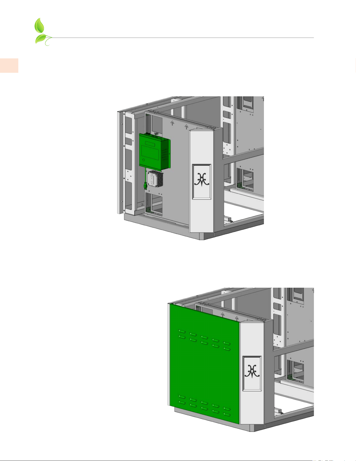
12. Mount the electrical box that came with your Hestan grill as shown and secure with #10 self-
drilling screws provided. Use the provided Wire Harness Extension (p/n 009938) to connect the
box to the grill wire harness. Arrange the wires in such a way to prevent damage during installation
of the grill, and to keep away from heat. At this point, it is also recommended the plumber run
the gas connections for the Grill and Side Burner (see pg. 20). As mentioned before, a gas shut-off
valve must be located in a readily accessible location for shut-off when the appliances are not in
use, or for servicing. See reference photos on pg. 21.
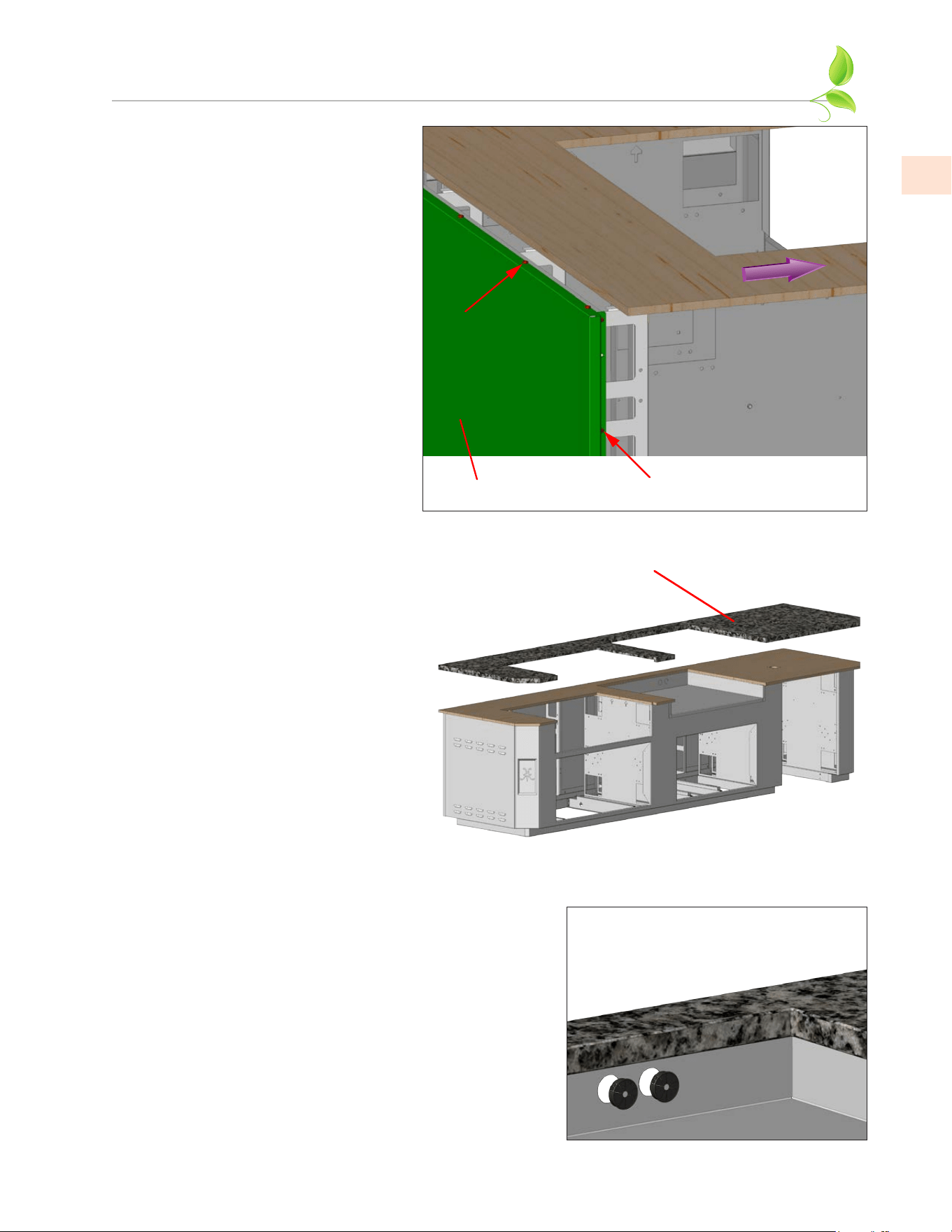
13. Mount the lift-off panel on the left side of the suite. This panel is used to access the electrical
box and gas shut-off valve when needed. There are pins on either side for locating the panel. The
louvers located on these side panels are needed for ventilation and must not be blocked. If this
lift-off panel does not install/remove easily, you may need to adjust the corner assembly(ies) to
accommodate (see Step 7).
NOTE: The top edge of this panel
may interfere with the plywood
substrate installed in the next
step. You may have to leave some
clearance in the plywood and/or
the stone overhangs so this lift-off
panel can be raised vertically for
access to the inside.
©2023 Hestan Commercial Corporation
15
EN
INSTALL SUPPORT STRUCTURE AND TOP
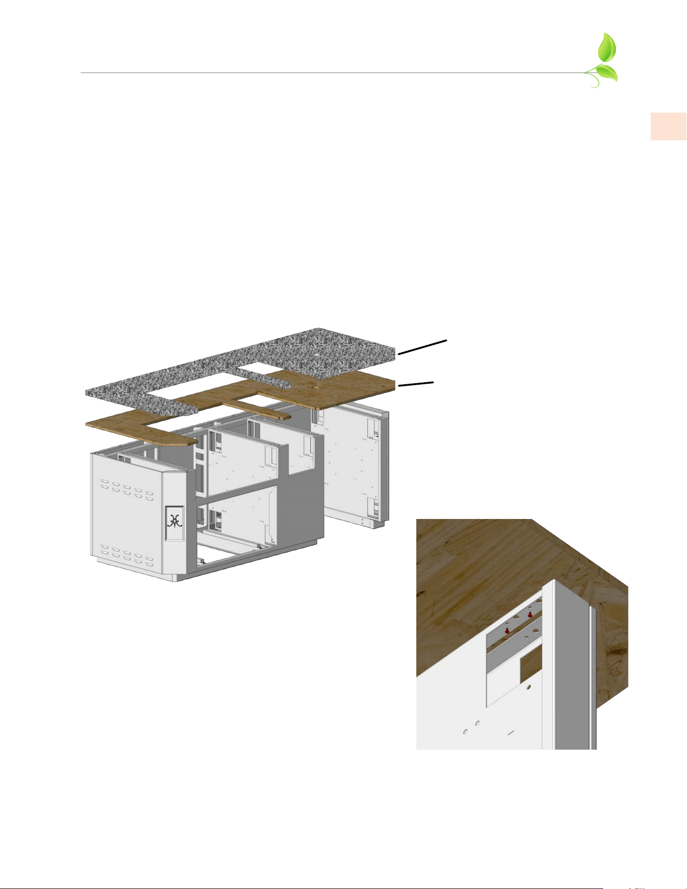
The Hestan Outdoor Living Suite DOES NOT include the stone countertop and plywood sub-
structure. Template drawings are provided at the end of this manual with RECOMMENDED final stone
dimensions. You may choose to have slightly larger overhangs, different edge treatments, etc. Assuming
you already chose a material, the installer will typically visit your home to go over the dimensions and
make a physical template of the top before cutting the slab you have chosen.
Note: Be advised that some stone products can discolor from exposure to the heat of the grill or other
gas-burning appliances. Consult with your countertop supplier on choosing an appropriate material.
The stone countertop must be supported beneath by a 3/4” [19mm] thick plywood substrate (see
below). Marine-grade/pressure-treated plywood is recommended because it is resistant to moisture,
rot, etc. A 1/2” [13mm] cement-board material may also be used, but will be more difficult to fasten to
the structural members of the suite. Be sure to arrange for this substrate to be provided with the stone
countertop at the time of installation. See “ NOTES ABOUT MATERIALS” on the template drawings at
the end of this manual.
14. Before installing the top, you should now go back and tighten all bolts everywhere else in the suite.
Install the plywood substrate first. Get assistance from another person to help lift the plywood and
position correctly. (8 foot Outdoor Living Suite shown)
STONE
PLYWOOD
YOUR STONE INSTALLER WILL COMPLETE THE ASSEMBLY OF THE SUITE COUNTERTOP.
YOU MAY THEN INSTALL THE APPLIANCES, CABINETS, AND OTHER PRODUCTS AS PER
THE INSTRUCTION MANUALS SUPPLIED WITH THOSE PRODUCTS.
NOTE: IF YOU HAVE A SUITE FOR POWER BURNER, KAMADO GRILL, OR PIZZA OVEN SEE THE
APPENDIX AT THE BACK OF THIS MANUAL FOR DETAILS BEFORE INSTALLING THE
COUNTERTOP.
Use coated or stainless steel 1/2”
long wood screws where needed to
attach the plywood to the vertical
walls in the small holes provided.
©2023 Hestan Commercial Corporation
16
EN
BAR TOP INSTALLATION (FOR MODELS WITH BAR)
HESTAN OUTDOOR LIVING SUITES WHICH FEATURE A BAR TOP (GESBx08 and GESBx12)
FOLLOW THE SAME STEPS AS DESCRIBED EARLIER IN THIS MANUAL. STEPS UNIQUE TO THESE
MODELS ARE DETAILED BELOW.
BACK AND SUPPORT WALL ASSEMBLY
1. Attach support wall #1 to curb assembly and back wall as shown using 6 each 1/4-20 x 1/2” hex bolts
and hex nuts where needed.
1/4-20 x 1/2” BOLTS
& NUTS HERE
2. Install remaining support walls as you did in step 1. Each wall is numbered and has a corresponding
number on the rear wall for ease of locating. (12 foot Outdoor Living Suite with Bar shown).
©2023 Hestan Commercial Corporation
17
EN
BAR TOP INSTALLATION
(continued)
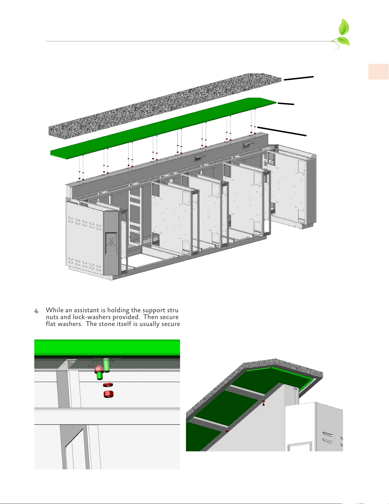
3. The stone bar top is supported by the included metal support structure as shown below. Get
assistance from another person to help lift the support and position correctly.
STONE
TOP
METAL
SUPPORT
STRUCTURE
NUTS &
WASHERS
4. While an assistant is holding the support structure in place, reach underneath and secure with 1/2”
nuts and lock-washers provided. Then secure the large back panels with 1/4-20 x 1/2” long bolts and
flat washers. The stone itself is usually secured with an adhesive provided by the stone installer.
©2023 Hestan Commercial Corporation
18
EN
APPLY SEALANT
ALONG THIS JOINT
HOLE FOR
OPTIONAL BEER
DISPENSER
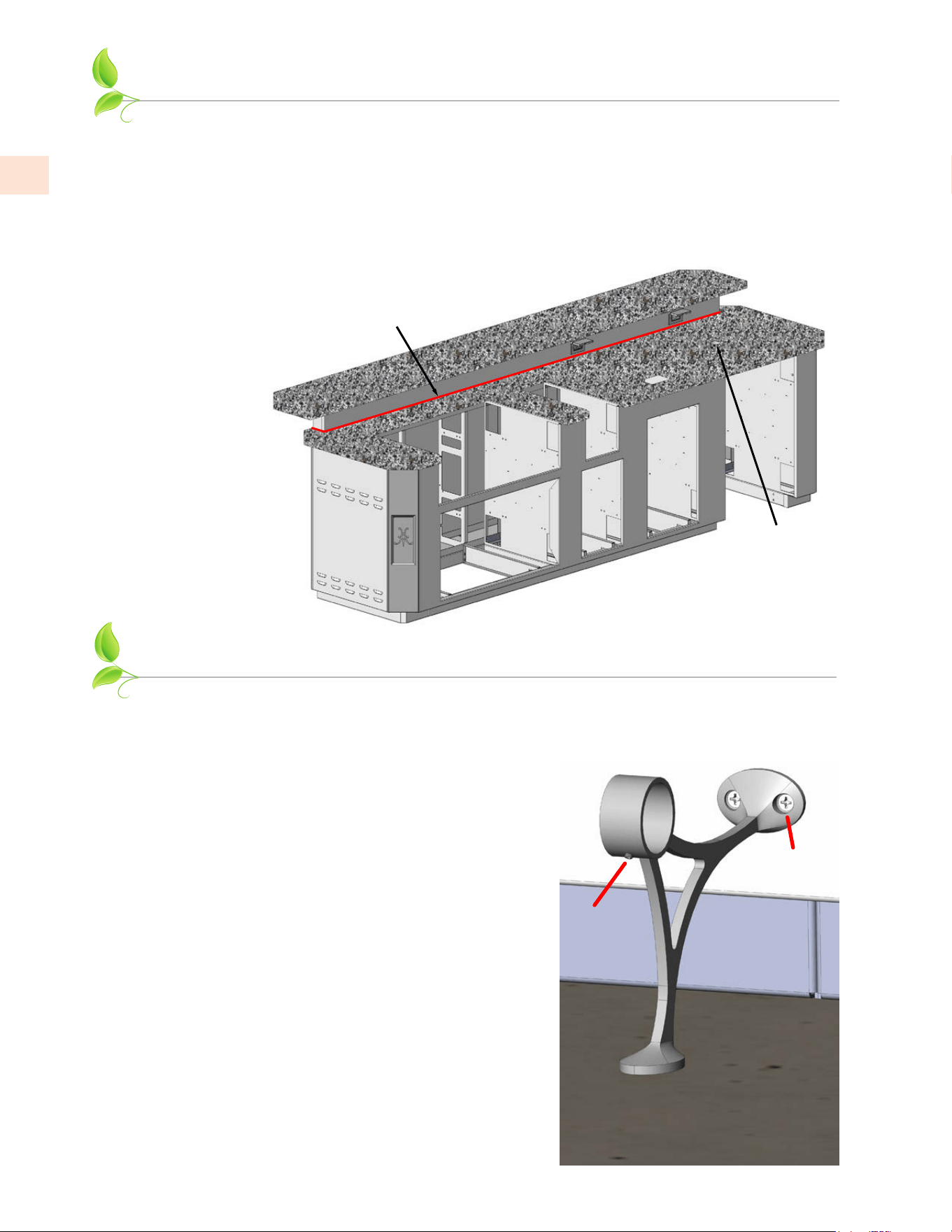
FOOTRAIL INSTALLATION (FOR MODELS WITH BAR)
SETSCREW
FLAT-HEAD
MOUNTING
SCREWS
1. With a helper’s assistance, install the footrail
brackets on the rear wall as shown using #10-24 x
1/2” long flat-head mounting screws and locknuts
on the opposite side of the wall. Do not fully
tighten the screws yet. There is minimal vertical
adjustment in these brackets to help with uneven
floors.
Check to see if the setscrew in each bracket is
backed out enough to allow the tube to pass
through easily.
NOTE: For installation of the footrail, it is assumed the curb base of the entire suite was installed
on a flat and level surface (see page 4). If the surface is not level, the bottom pads of each bracket
may not rest fully on this surface.
Also if you decide to tile around the suite after
installation, the bottom pads of the footrail will still
be on the same level as the underside of the curb base.
Your tile installation will need to make allowances for
this condition.
INSTALL COUNTERTOP
NOTE: IF YOU HAVE A SUITE FOR POWER BURNER, KAMADO GRILL, OR PIZZA OVEN
SEE THE APPENDIX AT THE BACK OF THIS MANUAL FOR DETAILS BEFORE
INSTALLING THE COUNTERTOP.
5. Install the countertop on top of the plywood sub-structure. Get assistance from another
person to help lift the top and position correctly. The stone itself is usually secured with
an adhesive provided by the stone installer. When complete, apply a bead of clear silicone
sealant along the joint indicated.
©2023 Hestan Commercial Corporation
19
EN
GAS CONNECTIONS AND FINAL ASSEMBLY
ASSEMBLY OF THE SUITE IS NOW COMPLETE. YOU MAY NOW INSTALL THE APPLIANCES,
CABINETS, AND OTHER PRODUCTS AS PER THE INSTRUCTION MANUALS SUPPLIED WITH
THOSE PRODUCTS.
GAS SUPPLY
Gas connections should be made by a qualified plumber, or your professional outdoor appliance installer.
All fixed (non-mobile) appliances must be fitted with an accessible upstream gas shutoff valve as a means
of isolating the appliance for emergency shut off and for servicing. See reference photo on pg. 21.
Make certain new piping and connections have been made in a clean manner and have been purged so that
piping compound, chips, etc. will not clog regulators, valves, orifices, or burners. Use pipe joint compound
/ thread sealant approved for natural and LP gases.
NEVER CONNECT THE GAS-BURNING APPLIANCE TO AN UNREGULATED GAS SUPPLY. Before
proceeding, ensure the appliance is fitted for Natural or Liquid Propane gas. Connecting to an improper
gas type will result in poor performance and increased risk of damage or injury. Gas type and gas
consumption (BTU per hour) for each burner type is shown on the rating label affixed to each appliance.
Installation of this cooking appliance must be made in accordance with local codes. In the absence of local
codes, this unit should be installed in accordance with the National Fuel Gas Code No.
Z223.1/ NFPA 54
,
Natural Gas and Propane Installation code
CSA B149-1
, or Propane Storage and Handling Code B149.2.
NOTE:NOTE: See rating label for manifold pressure for the type of gas of your appliance.
NOTE:NOTE: If your Suite is to be connected to a Whole-House LP Piped System, please read the GAS
CONNECTIONS section of the manual that came with your Hestan appliance for information on this
unique installation, and to contact Hestan Customer Service to order an LP Piped System Kit.
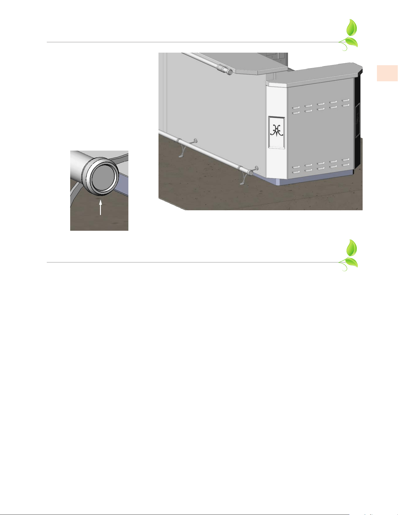
FOOTRAIL INSTALLATION
(continued)
2. Pass the textured tube through
all footrail brackets. Check
that an equal length of tubing is
exposed beyond the left-most
and right-most brackets. When
you are OK with the position,
lock the tube in place with all
setscrews. Tighten all mounting
bracket screws/nuts as well.
3. Attach endcaps to both ends
of the tube and secure with
setscrews on the bottom.
SETSCREW
©2023 Hestan Commercial Corporation
20
EN
GAS CONNECTIONS AND FINAL ASSEMBLY
(continued)
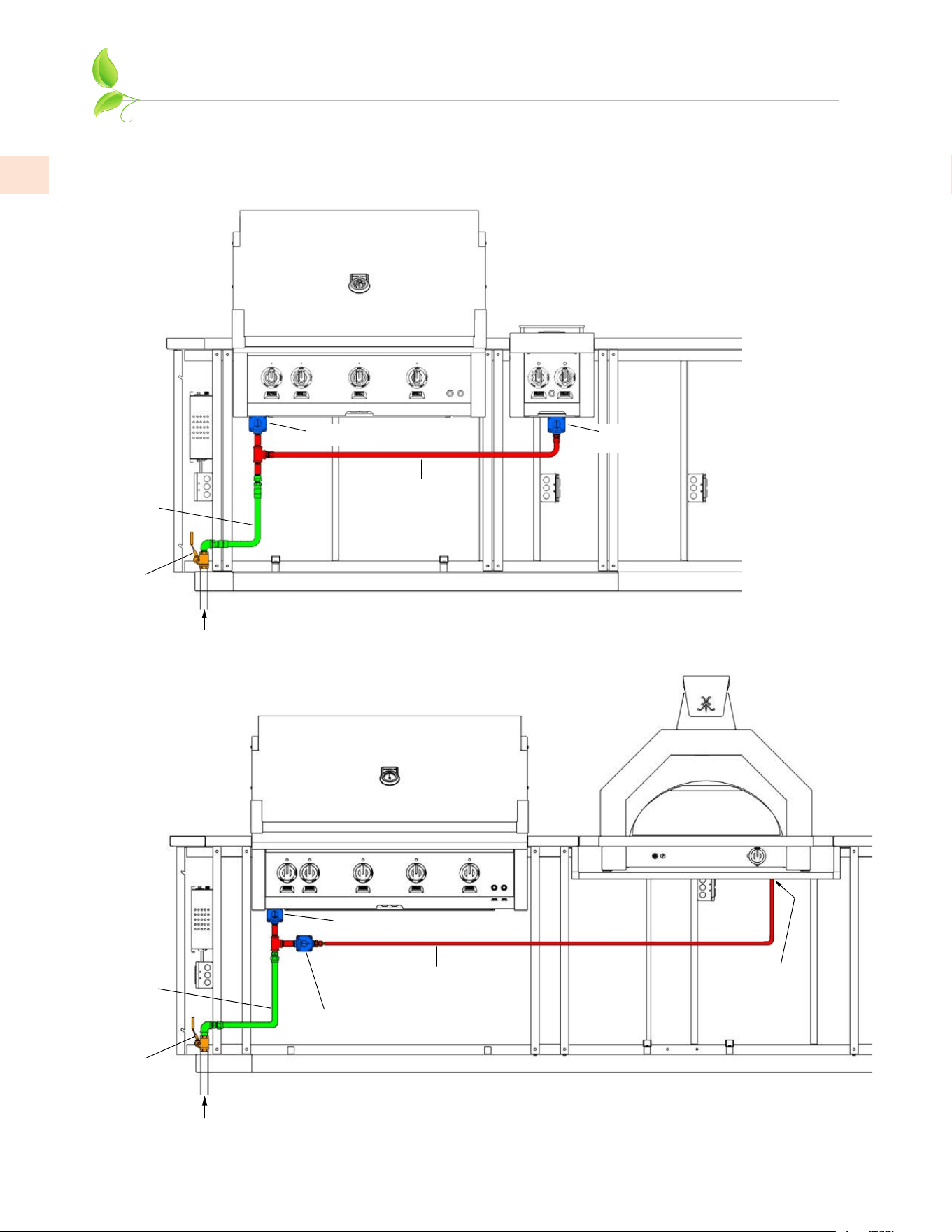
1. The Outdoor Living Suite is shipped with an interplumb kit to simplify connecting the Grill and
other appliances (such as a Side Burner, Power Burner or PIzza Oven) as shown below. HOWEVER,
EACH APPLIANCE MUST BE CONNECTED TO ITS OWN REGULATOR. DO NOT USE ONE
REGULATOR FOR BOTH APPLIANCES.
INTERPLUMB KIT
(SUPPLIED WITH SUITE)
FLEX HOSE
& FITTINGS
(SUPPLIED BY CUSTOMER)
SHUT-OFF
VALVE
(SUPPLIED BY CUSTOMER)
INCOMING
GAS SERVICE
SUITE WITH GRILL AND SIDE BURNER
(POWER BURNER IS SIMILAR)
REGULATOR
(SUPPLIED WITH GRILL)
REGULATOR
(SUPPLIED WITH
SIDE BURNER)
INTERPLUMB KIT
(SUPPLIED WITH SUITE)
FLEX HOSE
& FITTINGS
(SUPPLIED BY CUSTOMER)
SHUT-OFF
VALVE
(SUPPLIED BY CUSTOMER)
INCOMING
GAS SERVICE
SUITE WITH GRILL AND PIZZA OVEN
REGULATOR
(SUPPLIED WITH GRILL)
END OF THIS
HOSE CONNECTS
DIRECTLY TO
PIZZA OVEN
REGULATOR
(SUPPLIED WITH PIZZA OVEN)

©2023 Hestan Commercial Corporation
21
EN
REFERENCE PHOTOS
GRILL HARNESS
EXTENSION
P/N 009938
INCOMING
ELECTRICAL
SUPPLY
GRILL
ELECTRICAL
BOX
ELECTRICAL AND GAS CONNECTIONS
SUPPLIED BY CUSTOMER
INCOMING GAS SUPPLY
w/ SHUTOFF VALVE,
ELBOW & FLEX HOSE
2. The remaining gas connections shown on the previous page must be completed by the qualified plumber
or professional outdoor appliance installer. See reference photo below for typical flex hose and shut-
off valve location. Flex hose, shut-off valve, and misc. fittings must be provided by the homeowner
and installed by the qualified plumber or professional outdoor appliance installer. The gas regulator is
supplied with each appliance.
The images on the previous page are a suggestion only. Depending on which cabinetry was selected to
go beneath the grill, it may be necessary for the plumber to route the regulator, fittings, and hoses in a
different configuration to allow for the installation of the cabinet.
At all times, the shut-off valve must be located near the left side of the suite, near the floor, so it is easily
accessible for service or emergency shut-off (see reference photos below).
A FULL LEAK TEST MUST BE PERFORMED ON ALL GAS CONNECTIONS AND HOSES BEFORE
USING THE APPLIANCES. Refer to the appliance manuals for instructions on this very important step.
©2023 Hestan Commercial Corporation
22
EN
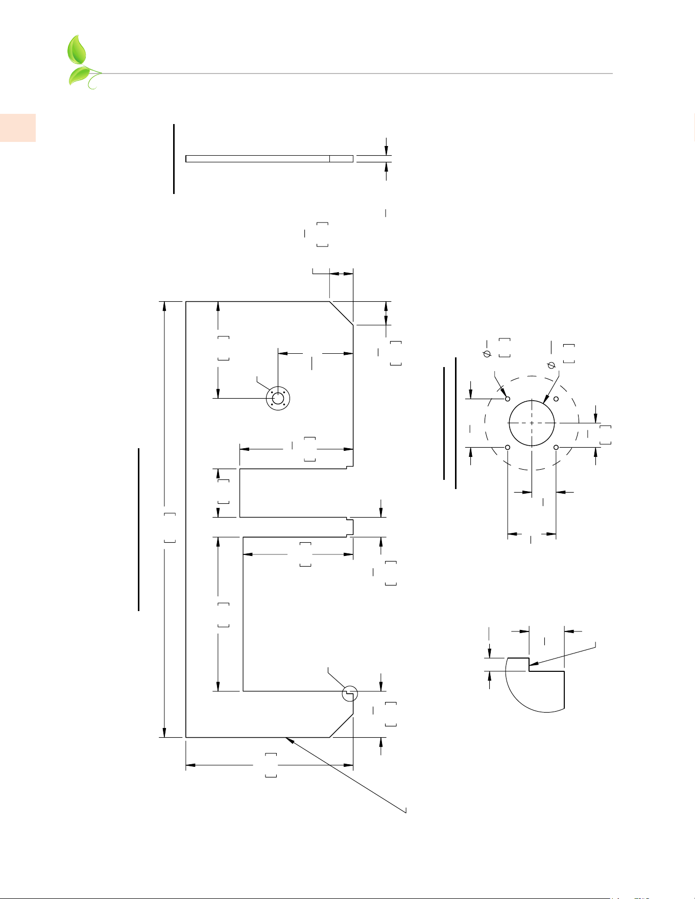
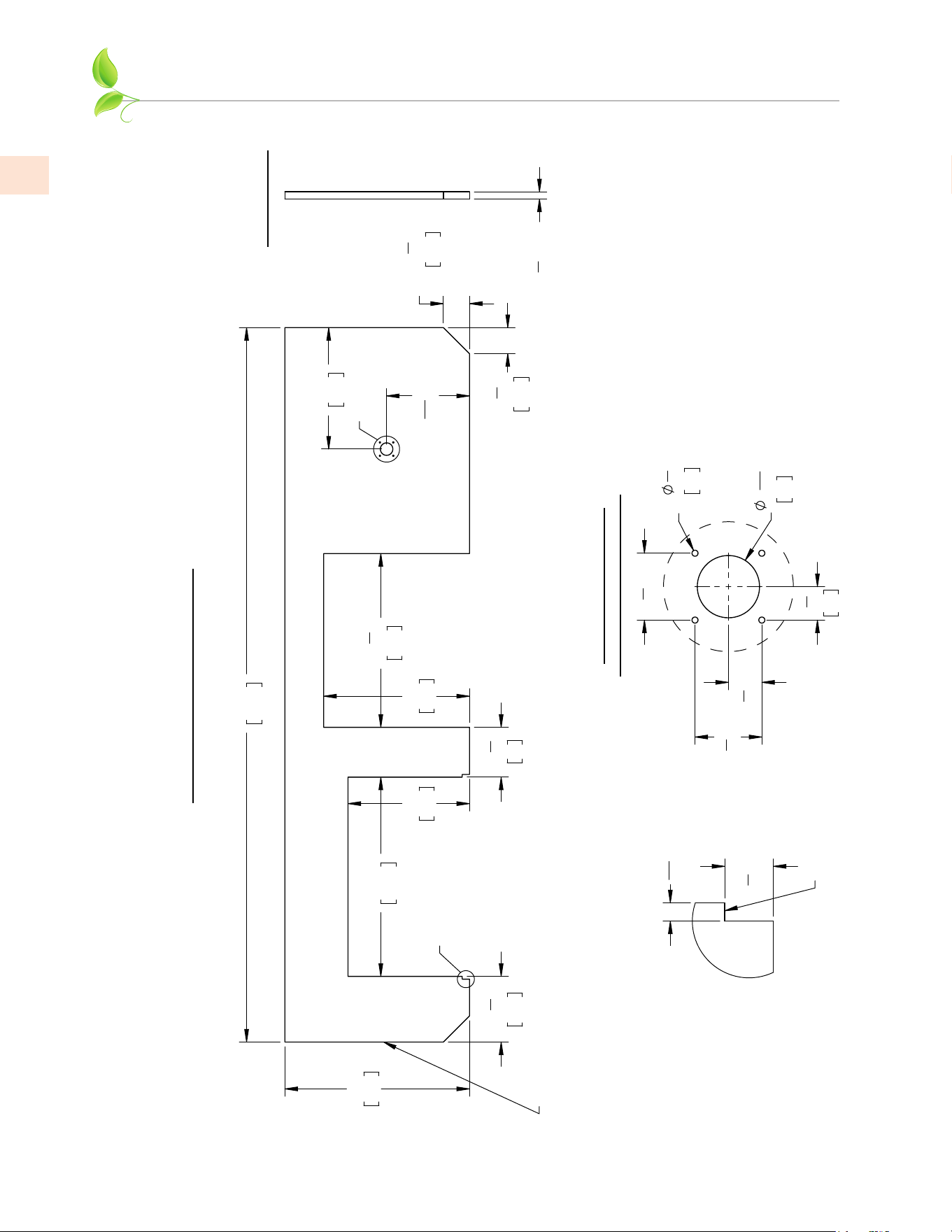
RECOMMENDED STONE DIMENSIONS
38"
96.5
99"
251.5
35"
88.9
11"
27.9
25"
63.5
25
3
4
"
65.4
10
1
2
"
26.7
4
1
2
"
11.4
22"
55.9
17
1
16
" [43.3]
2X
5
3
8
"
13.7
2X
5
3
8
"
13.7
A
B
TOP VIEW (8' COUNTERTOP)
REMOVABLE ACCESS PANEL
LOCATED ON THIS END OF
THE FINISHED SUITE.
IT MAY BE NECESSARY TO
LEAVE SOME CLEARANCE IN
THE SUBSTRATE TO ALLOW
THE PANEL TO BE LIFTED
UP THEN OUT.
2
9
16
"
6.5
4X
1
4
"
0.6
2
3
4
" [7]
2
3
4
" [7]
1
3
8
"
3.5
1
3
8
" [3.5]
DETAIL A
OPTIONAL CUTOUT
FOR BEER DISPENSER
1
1
2
" [3.8]
RIGHT VIEW
SUGGESTED HEIGHT
(INCLUDING SUBSTRATE)
9
16
"[1.4]
1
1
2
" [3.8]
DETAIL B
THIS SURFACE TO
BE FLUSH WITH
SUITE FRONT PANEL.
NOTES ABOUT MATERIALS:
Stone countertops are typically 20mm (.78 inch) or 30mm
(1.18 inch) thick. Stone fabricators typically provide a
double-thick edge around the perimeter which gets an edge
treatment (bullnose, etc.) The 1-1/2" suggested height
including substrate assumes a 20mm stone was used.
This installation manual recommends 3/4" thick marine-grade
plywood substrate which is resistant to moisture, rot, etc.
A 1/2" cement-board material may also be used, but will be
more difficult to fasten to the structural members of the suite.
DIMENSIONS IN [ ] ARE CM.
GES08: RECOMMENDED DIMENSIONS - COUNTERTOP, NO BAR (8 FT.)
©2023 Hestan Commercial Corporation
23
EN
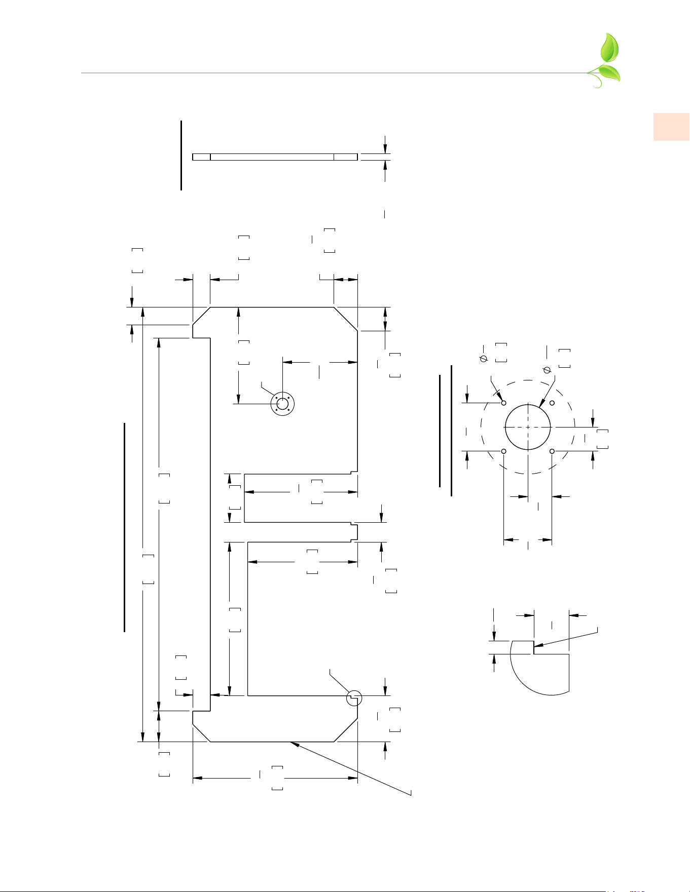
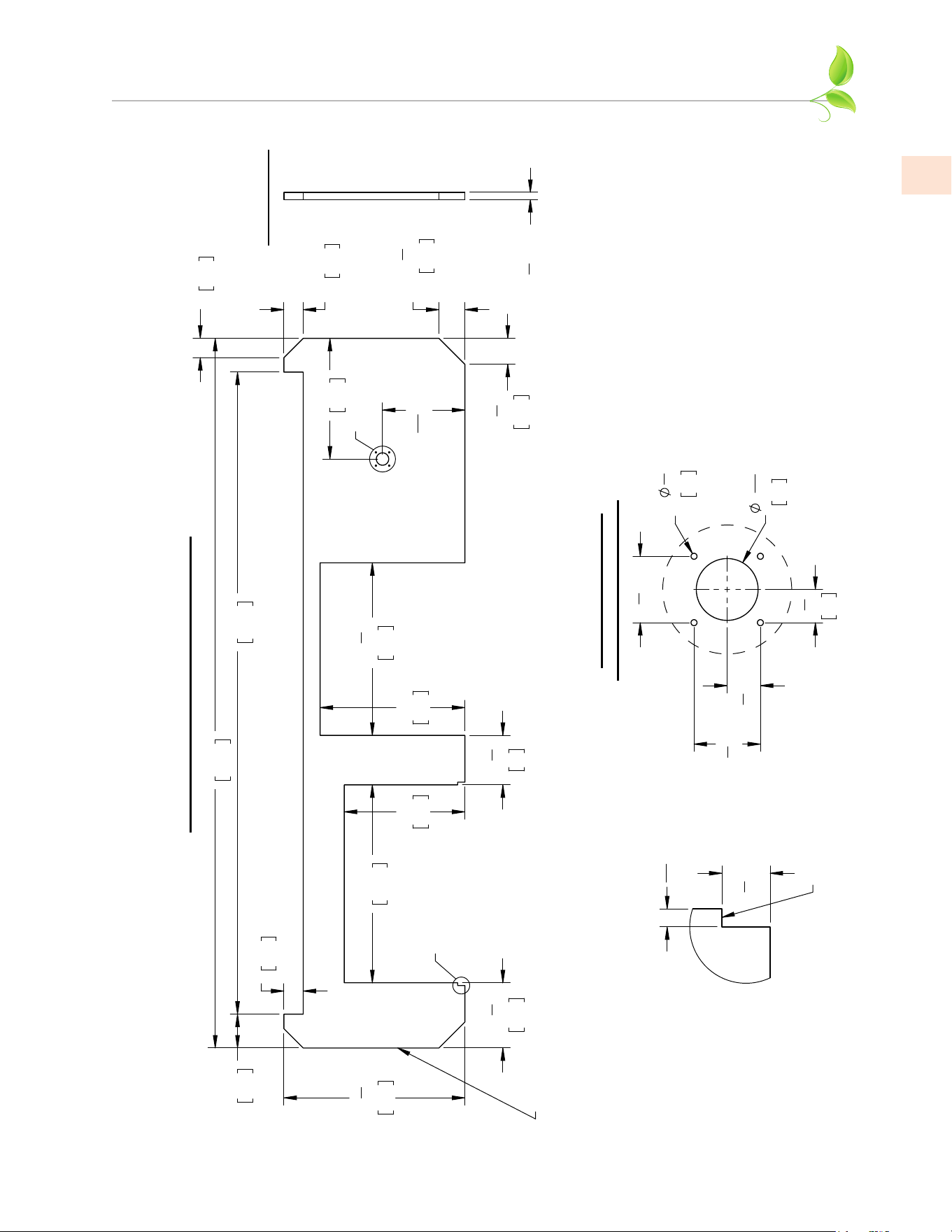
RECOMMENDED STONE DIMENSIONS
(continued)
37
1
2
"
95.3
10
1
2
"
26.7
7"
17.8
4"
10.2
99"
251.5
85"
215.9
35"
88.9
11"
27.9
25"
63.5
4
1
2
"
11.4
25
3
4
"
65.4
22"
55.9
17
1
16
" [43.3]
2X
4"
10.2
2X
4"
10.2
2X
5
3
8
"
13.7
2X
5
3
8
"
13.7
A
B
TOP VIEW (8' COUNTERTOP W/ BAR)
REMOVABLE ACCESS PANEL
LOCATED ON THIS END OF
THE FINISHED SUITE.
IT MAY BE NECESSARY TO
LEAVE SOME CLEARANCE IN
THE SUBSTRATE TO ALLOW
THE PANEL TO BE LIFTED
UP THEN OUT.
2
9
16
"
6.5
4X
1
4
"
0.6
2
3
4
" [7]
2
3
4
" [7]
1
3
8
" [3.5]
1
3
8
"
3.5
DETAIL A
OPTIONAL CUTOUT
FOR BEER DISPENSER
1
1
2
" [3.8]
RIGHT VIEW
SUGGESTED HEIGHT
(INCLUDING SUBSTRATE)
9
16
" [1.4]
1
1
2
" [3.8]
DETAIL B
THIS SURFACE TO
BE FLUSH WITH
SUITE FRONT PANEL.
NOTES ABOUT MATERIALS:
Stone countertops are typically 20mm (.78 inch) or 30mm
(1.18 inch) thick. Stone fabricators typically provide a
double-thick edge around the perimeter which gets an edge
treatment (bullnose, etc.) The 1-1/2" suggested height
including substrate assumes a 20mm stone was used.
This installation manual recommends 3/4" thick marine-grade
plywood substrate which is resistant to moisture, rot, etc.
A 1/2" cement-board material may also be used, but will be
more difficult to fasten to the structural members of the suite.
DIMENSIONS IN [ ] ARE CM.
GESB08: RECOMMENDED DIMENSIONS - COUNTERTOP, WITH BAR (8 FT.)
©2023 Hestan Commercial Corporation
24
EN
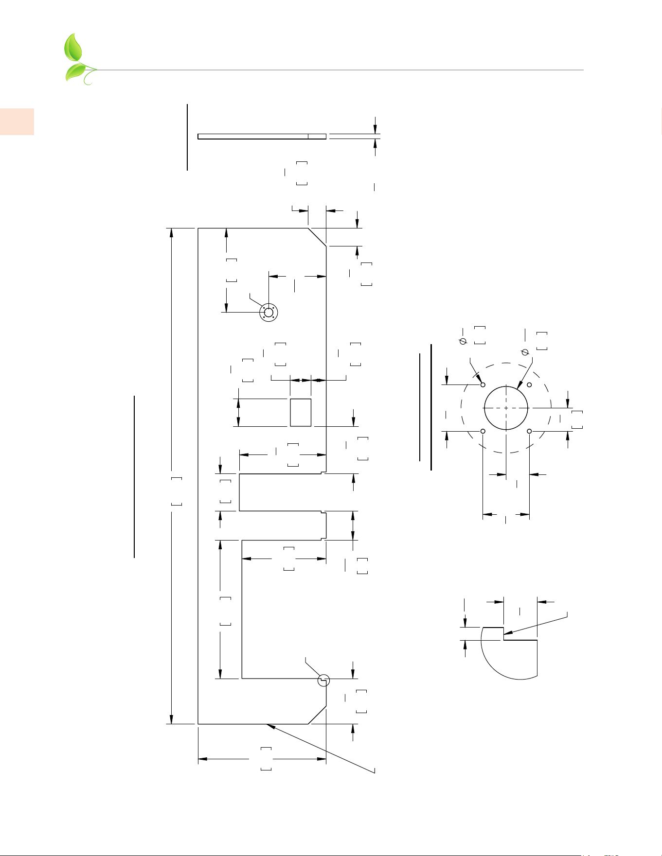
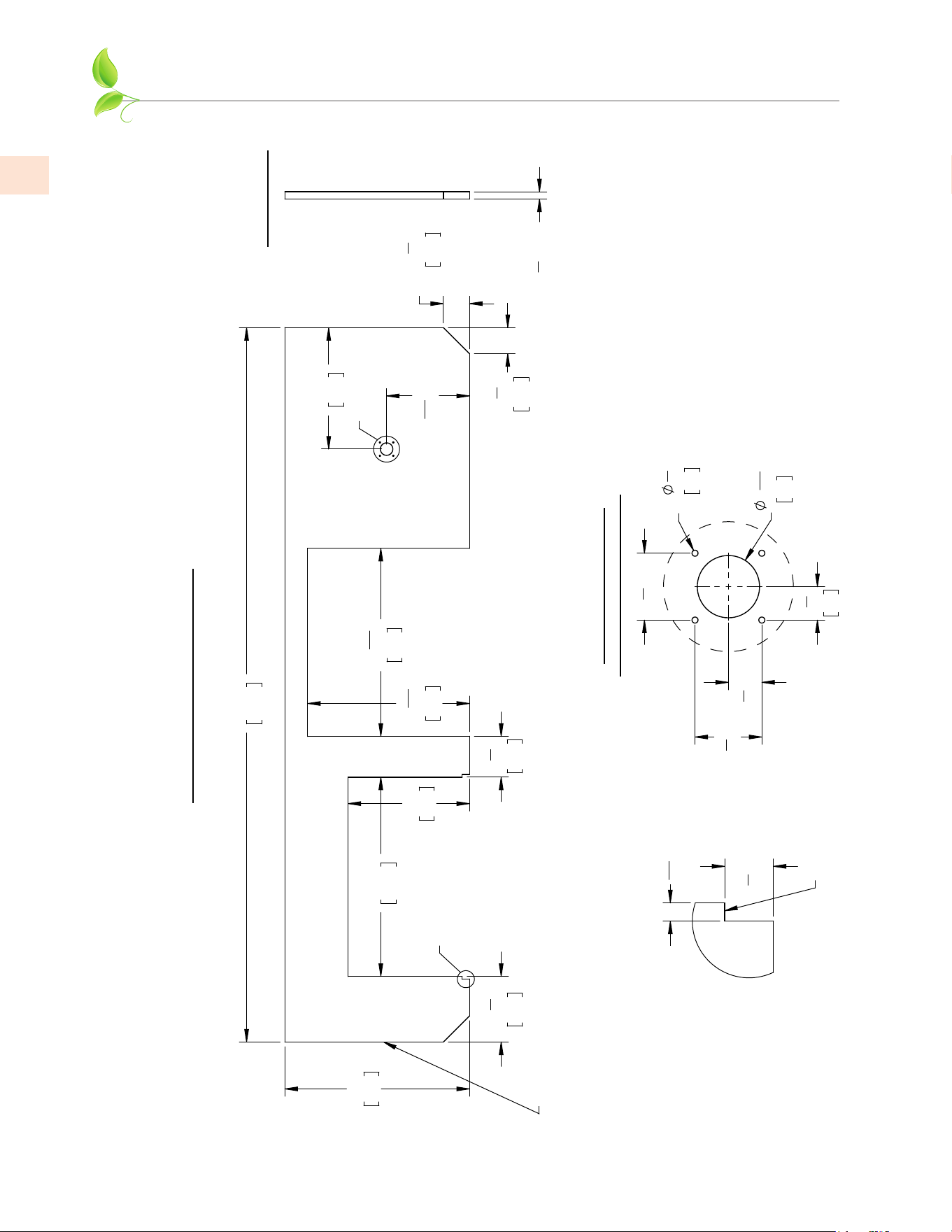
RECOMMENDED STONE DIMENSIONS
(continued)
41"
104.1
147"
373.4
38"
96.5
13
1
2
"
34.3
8
11
16
"
22
25"
63.5
11"
27.9
25
3
4
"
65.4
14
1
8
"
35.8
6
1
8
"
15.6
8
1
8
"
20.6
4
1
2
"
11.4
25"
63.5
17
1
16
" [43.3]
2X
5
3
8
"
13.7
2X
5
3
8
"
13.7
A
B
TOP VIEW (12' COUNTERTOP)
REMOVABLE ACCESS PANEL
LOCATED ON THIS END OF
THE FINISHED SUITE.
IT MAY BE NECESSARY TO
LEAVE SOME CLEARANCE IN
THE SUBSTRATE TO ALLOW
THE PANEL TO BE LIFTED
UP THEN OUT.
2
9
16
"
6.5
4X
1
4
"
0.6
2
3
4
" [7]
2
3
4
" [7]
1
3
8
" [3.5]
1
3
8
"
3.5
DETAIL A
OPTIONAL CUTOUT
FOR BEER DISPENSER
1
1
2
" [3.8]
RIGHT VIEW
SUGGESTED HEIGHT
(INCLUDING SUBSTRATE)
9
16
" [1.4]
1
1
2
" [3.8]
DETAIL B
THIS SURFACE TO
BE FLUSH WITH
SUITE FRONT PANEL.
NOTES ABOUT MATERIALS:
Stone countertops are typically 20mm (.78 inch) or 30mm
(1.18 inch) thick. Stone fabricators typically provide a
double-thick edge around the perimeter which gets an edge
treatment (bullnose, etc.) The 1-1/2" suggested height
including substrate assumes a 20mm stone was used.
This installation manual recommends 3/4" thick marine-grade
plywood substrate which is resistant to moisture, rot, etc.
A 1/2" cement-board material may also be used, but will be
more difficult to fasten to the structural members of the suite.
DIMENSIONS IN [ ] ARE CM.
GES12: RECOMMENDED DIMENSIONS - COUNTERTOP, NO BAR (12 FT.)
©2023 Hestan Commercial Corporation
25
EN
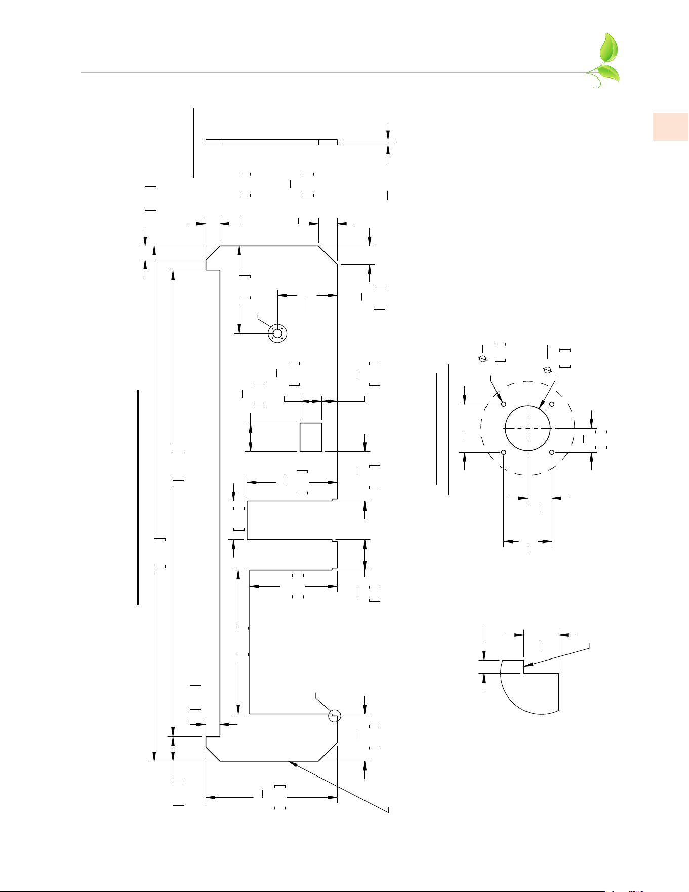
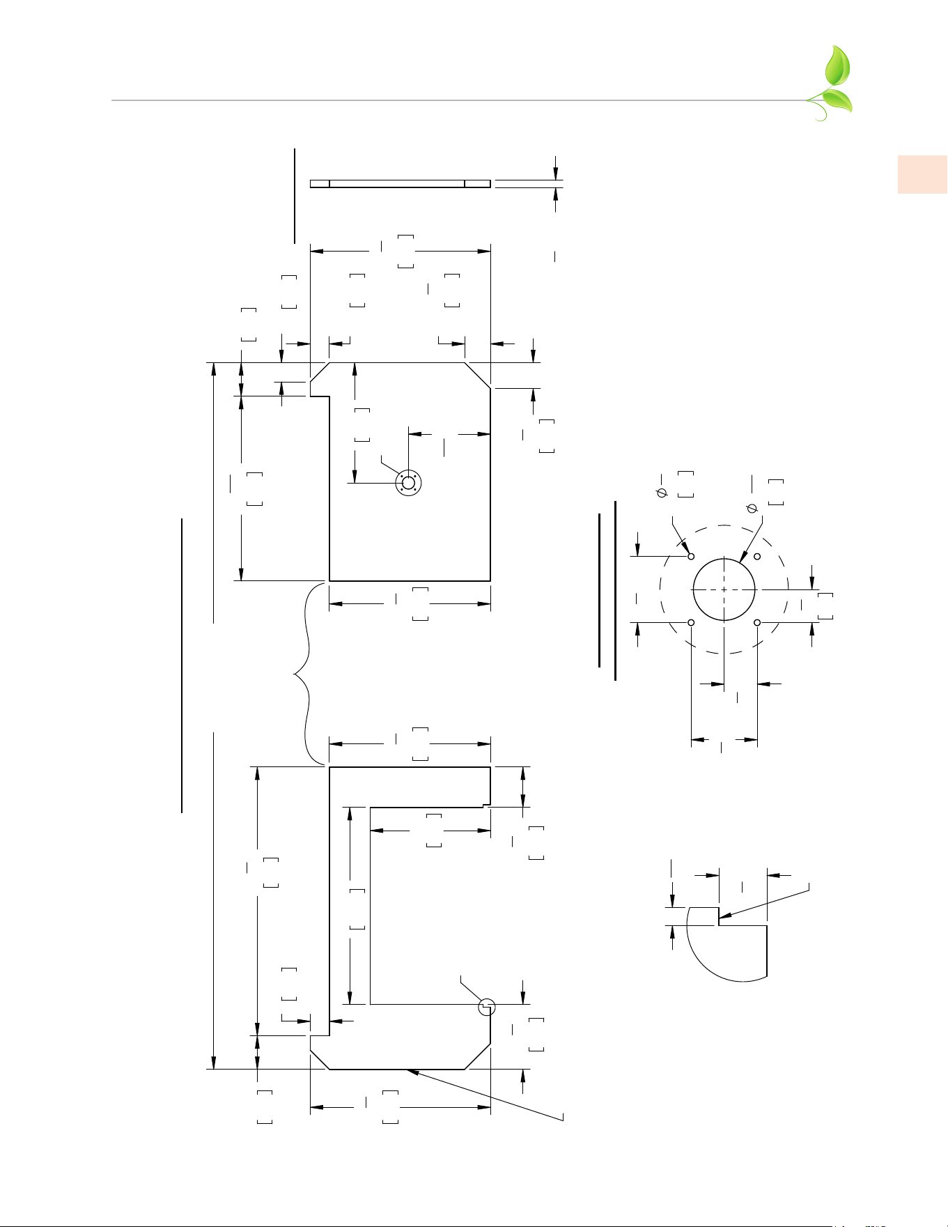
RECOMMENDED STONE DIMENSIONS
(continued)
147"
373.4
37
1
2
"
95.3
2X
4"
10.2
2X
4"
10.2
133"
337.8
7"
17.8
2X
5
3
8
"
13.7
2X
5
3
8
"
13.7
4"
10.2
41"
104.1
11"
27.9
25
3
4
"
65.4
8
1
8
"
20.6
6
1
8
"
15.6
25"
63.5
13
1
2
"
34.3
8
11
16
"
22
14
1
8
"
35.8
4
1
2
"
11.4
17
1
16
" [43.3]
25"
63.5
A
B
TOP VIEW (12' COUNTERTOP W/ BAR)
REMOVABLE ACCESS PANEL
LOCATED ON THIS END OF
THE FINISHED SUITE.
IT MAY BE NECESSARY TO
LEAVE SOME CLEARANCE IN
THE SUBSTRATE TO ALLOW
THE PANEL TO BE LIFTED
UP THEN OUT.
2
9
16
"
6.5
2
3
4
" [7]
2
3
4
" [7]
4X
1
4
"
0.6
1
3
8
"
3.5
1
3
8
" [3.5]
DETAIL A
OPTIONAL CUTOUT
FOR BEER DISPENSER
1
1
2
" [3.8]
RIGHT VIEW
SUGGESTED HEIGHT
(INCLUDING SUBSTRATE)
1
1
2
" [3.8]
9
16
" [1.4]
DETAIL B
THIS SURFACE TO
BE FLUSH WITH
SUITE FRONT PANEL.
NOTES ABOUT MATERIALS:
Stone countertops are typically 20mm (.78 inch) or 30mm
(1.18 inch) thick. Stone fabricators typically provide a
double-thick edge around the perimeter which gets an edge
treatment (bullnose, etc.) The 1-1/2" suggested height
including substrate assumes a 20mm stone was used.
This installation manual recommends 3/4" thick marine-grade
plywood substrate which is resistant to moisture, rot, etc.
A 1/2" cement-board material may also be used, but will be
more difficult to fasten to the structural members of the suite.
DIMENSIONS IN [ ] ARE CM.
GESB12: RECOMMENDED DIMENSIONS - COUNTERTOP, WITH BAR (12 FT.)
©2023 Hestan Commercial Corporation
26
EN
RECOMMENDED STONE DIMENSIONS
(continued)
2X
5
3
8
"
13.7
2X
5
3
8
"
13.7
17
1
16
" [43.3]
25"
63.5
25"
63.5
41"
104.1
13
1
2
"
34.3
38"
96.5
147"
373.4
10
1
4
"
26
35
3
4
"
90.8
30"
76.2
A
B
TOP VIEW (12' COUNTERTOP)
REMOVABLE ACCESS PANEL
LOCATED ON THIS END OF
THE FINISHED SUITE.
IT MAY BE NECESSARY TO
LEAVE SOME CLEARANCE IN
THE SUBSTRATE TO ALLOW
THE PANEL TO BE LIFTED
UP THEN OUT.
2
9
16
"
6.5
4X
1
4
"
0.6
2
3
4
" [7]
2
3
4
" [7]
1
3
8
" [3.5]
1
3
8
"
3.5
DETAIL A
OPTIONAL CUTOUT
FOR BEER DISPENSER
1
1
2
" [3.8]
RIGHT VIEW
SUGGESTED HEIGHT
(INCLUDING SUBSTRATE)
9
16
" [1.4]
1
1
2
" [3.8]
DETAIL B
THIS SURFACE TO
BE FLUSH WITH
SUITE FRONT PANEL.
NOTES ABOUT MATERIALS:
Stone countertops are typically 20mm (.78 inch) or 30mm
(1.18 inch) thick. Stone fabricators typically provide a
double-thick edge around the perimeter which gets an edge
treatment (bullnose, etc.) The 1-1/2" suggested height
including substrate assumes a 20mm stone was used.
This installation manual recommends 3/4" thick marine-grade
plywood substrate which is resistant to moisture, rot, etc.
A 1/2" cement-board material may also be used, but will be
more difficult to fasten to the structural members of the suite.
DIMENSIONS IN [ ] ARE CM.
GESP/K12: RECOMMENDED DIMENSIONS - COUNTERTOP, NO BAR (12 FT.)
©2023 Hestan Commercial Corporation
27
EN
RECOMMENDED STONE DIMENSIONS
(continued)
147"
373.4
37
1
2
"
95.3
2X
4"
10.2
2X
4"
10.2
133"
337.8
7"
17.8
2X
5
3
8
"
13.7
2X
5
3
8
"
13.7
4"
10.2
41"
104.1
25"
63.5
13
1
2
"
34.3
10
1
4
"
26
17
1
16
" [43.3]
25"
63.5
35
3
4
"
90.8
30"
76.2
A
B
TOP VIEW (12' COUNTERTOP W/ BAR)
REMOVABLE ACCESS PANEL
LOCATED ON THIS END OF
THE FINISHED SUITE.
IT MAY BE NECESSARY TO
LEAVE SOME CLEARANCE IN
THE SUBSTRATE TO ALLOW
THE PANEL TO BE LIFTED
UP THEN OUT.
2
9
16
"
6.5
2
3
4
" [7]
2
3
4
" [7]
4X
1
4
"
0.6
1
3
8
"
3.5
1
3
8
" [3.5]
DETAIL A
OPTIONAL CUTOUT
FOR BEER DISPENSER
1
1
2
" [3.8]
RIGHT VIEW
SUGGESTED HEIGHT
(INCLUDING SUBSTRATE)
1
1
2
" [3.8]
9
16
" [1.4]
DETAIL B
THIS SURFACE TO
BE FLUSH WITH
SUITE FRONT PANEL.
NOTES ABOUT MATERIALS:
Stone countertops are typically 20mm (.78 inch) or 30mm
(1.18 inch) thick. Stone fabricators typically provide a
double-thick edge around the perimeter which gets an edge
treatment (bullnose, etc.) The 1-1/2" suggested height
including substrate assumes a 20mm stone was used.
This installation manual recommends 3/4" thick marine-grade
plywood substrate which is resistant to moisture, rot, etc.
A 1/2" cement-board material may also be used, but will be
more difficult to fasten to the structural members of the suite.
DIMENSIONS IN [ ] ARE CM.
GESBP/K12:
RECOMMENDED DIMENSIONS - COUNTERTOP, WITH BAR (12 FT.)
©2023 Hestan Commercial Corporation
28
EN
RECOMMENDED STONE DIMENSIONS
(continued)
2X
5
3
8
"
13.7
2X
5
3
8
"
13.7
17
1
16
" [43.3]
25"
63.5
25"
63.5
41"
104.1
13
1
2
"
34.3
38"
96.5
147"
373.4
8
3
8
"
21.3
38
11
16
"
98.3
33
5
16
"
84.6
A
B
TOP VIEW (12' COUNTERTOP)
REMOVABLE ACCESS PANEL
LOCATED ON THIS END OF
THE FINISHED SUITE.
IT MAY BE NECESSARY TO
LEAVE SOME CLEARANCE IN
THE SUBSTRATE TO ALLOW
THE PANEL TO BE LIFTED
UP THEN OUT.
2
9
16
"
6.5
4X
1
4
"
0.6
2
3
4
" [7]
2
3
4
" [7]
1
3
8
" [3.5]
1
3
8
"
3.5
DETAIL A
OPTIONAL CUTOUT
FOR BEER DISPENSER
1
1
2
" [3.8]
RIGHT VIEW
SUGGESTED HEIGHT
(INCLUDING SUBSTRATE)
9
16
" [1.4]
1
1
2
" [3.8]
DETAIL B
THIS SURFACE TO
BE FLUSH WITH
SUITE FRONT PANEL.
NOTES ABOUT MATERIALS:
Stone countertops are typically 20mm (.78 inch) or 30mm
(1.18 inch) thick. Stone fabricators typically provide a
double-thick edge around the perimeter which gets an edge
treatment (bullnose, etc.) The 1-1/2" suggested height
including substrate assumes a 20mm stone was used.
This installation manual recommends 3/4" thick marine-grade
plywood substrate which is resistant to moisture, rot, etc.
A 1/2" cement-board material may also be used, but will be
more difficult to fasten to the structural members of the suite.
DIMENSIONS IN [ ] ARE CM.
GESC12: RECOMMENDED DIMENSIONS - COUNTERTOP, NO BAR (12 FT.)
©2023 Hestan Commercial Corporation
29
EN
RECOMMENDED STONE DIMENSIONS
(continued)
2X
4"
10.2
2X
4"
10.2
2X
5
3
8
"
13.7
2X
5
3
8
"
13.7
17
1
16
" [43.3]
25"
63.5
41"
104.1
25"
63.5
4"
10.2
7"
17.8
55
7
8
"
142
33
1
2
"
85.1
37
1
2
"
95.3
13
1
2
"
34.3
8
3
8
"
21.3
38
7
16
"
97.6
7"
17.8
147" [373.4] REF.
OVERALL
FINISHED SUITE
37
1
2
"
95.3
33
1
2
"
85.1
A
B
TOP VIEW (12' COUNTERTOP W/ BAR)
REMOVABLE ACCESS PANEL
LOCATED ON THIS END OF
THE FINISHED SUITE.
IT MAY BE NECESSARY TO
LEAVE SOME CLEARANCE IN
THE SUBSTRATE TO ALLOW
THE PANEL TO BE LIFTED
UP THEN OUT.
ALCOVE AREA
2
9
16
"
6.5
2
3
4
" [7]
2
3
4
" [7]
4X
1
4
"
0.6
1
3
8
"
3.5
1
3
8
" [3.5]
DETAIL A
OPTIONAL CUTOUT
FOR BEER DISPENSER
1
1
2
" [3.8]
RIGHT VIEW
SUGGESTED HEIGHT
(INCLUDING SUBSTRATE)
1
1
2
"[3.8]
9
16
" [1.4]
DETAIL B
THIS SURFACE TO
BE FLUSH WITH
SUITE FRONT PANEL.
NOTES ABOUT MATERIALS:
Stone countertops are typically 20mm (.78 inch) or 30mm
(1.18 inch) thick. Stone fabricators typically provide a
double-thick edge around the perimeter which gets an edge
treatment (bullnose, etc.) The 1-1/2" suggested height
including substrate assumes a 20mm stone was used.
This installation manual recommends 3/4" thick marine-grade
plywood substrate which is resistant to moisture, rot, etc.
A 1/2" cement-board material may also be used, but will be
more difficult to fasten to the structural members of the suite.
DIMENSIONS IN [ ] ARE CM.
GESBC12:
RECOMMENDED DIMENSIONS - COUNTERTOP, WITH BAR (12 FT.)

©2023 Hestan Commercial Corporation
30
EN
RECOMMENDED STONE DIMENSIONS
(continued)
1
1
2
"
8
3
"
4
147"
3
17
2X 5
2X 5
3
8
"
"
SUGGESTED
HEIGHT
(INCLUDING
SUBSTRATE)
1
1
2
"
SUGGESTED
HEIGHT
(INCLUDING
SUBSTRATE)
8
3
" 2X 5
2X 5
3
8
"
RECOMMENDED DIMENSIONS
BAR TOP, 8 FT.
RECOMMENDED DIMENSIONS
BAR TOP, 12 FT.
45.1
13.7
13.7
99"
251.5
373.4
DIMENSIONS IN [ ] ARE CM.
4
3
17 "
45.1
13.7
13.7
3.8
3.8
NOTES ABOUT MATERIALS:
Stone countertops are typically 20mm (.78 inch) or 30mm
(1.18 inch) thick. Stone fabricators typically provide a
double-thick edge around the perimeter which gets an edge
treatment (bullnose, etc.) The 1-1/2" suggested height
including substrate assumes a 20mm stone was used.
©2023 Hestan Commercial Corporation
31
EN
APPENDIX - POWER BURNER SUITES
POWER BURNER
ALCOVE
PLYWOOD
STONE
1. The Outdoor Living Suite with Power Burner features an alcove for the appliance which must be
set in place as shown below, then the plywood sub-structure must be secured, then the large stone
countertop. Get assistance from another person to help lift the top and position correctly.
#8-32 X 3/8”
FLAT-HEAD
SCREW -
2 PLACES
2. There are two (2) #8-32 x 3/8” flathead
countersunk screws which attach the alcove
to the front panel.
©2023 Hestan Commercial Corporation
32
EN
APPENDIX - POWER BURNER SUITES
(continued)
3. Use coated or stainless steel 1/2” long wood screws where needed to secure the vertical walls and
alcove to the underside of the plywood, using the small holes provided.
Tighten any remaining bolts underneath and return to step 5 on pg. 18 to complete the procedure.
©2023 Hestan Commercial Corporation
33
EN
APPENDIX - KAMADO GRILL SUITES
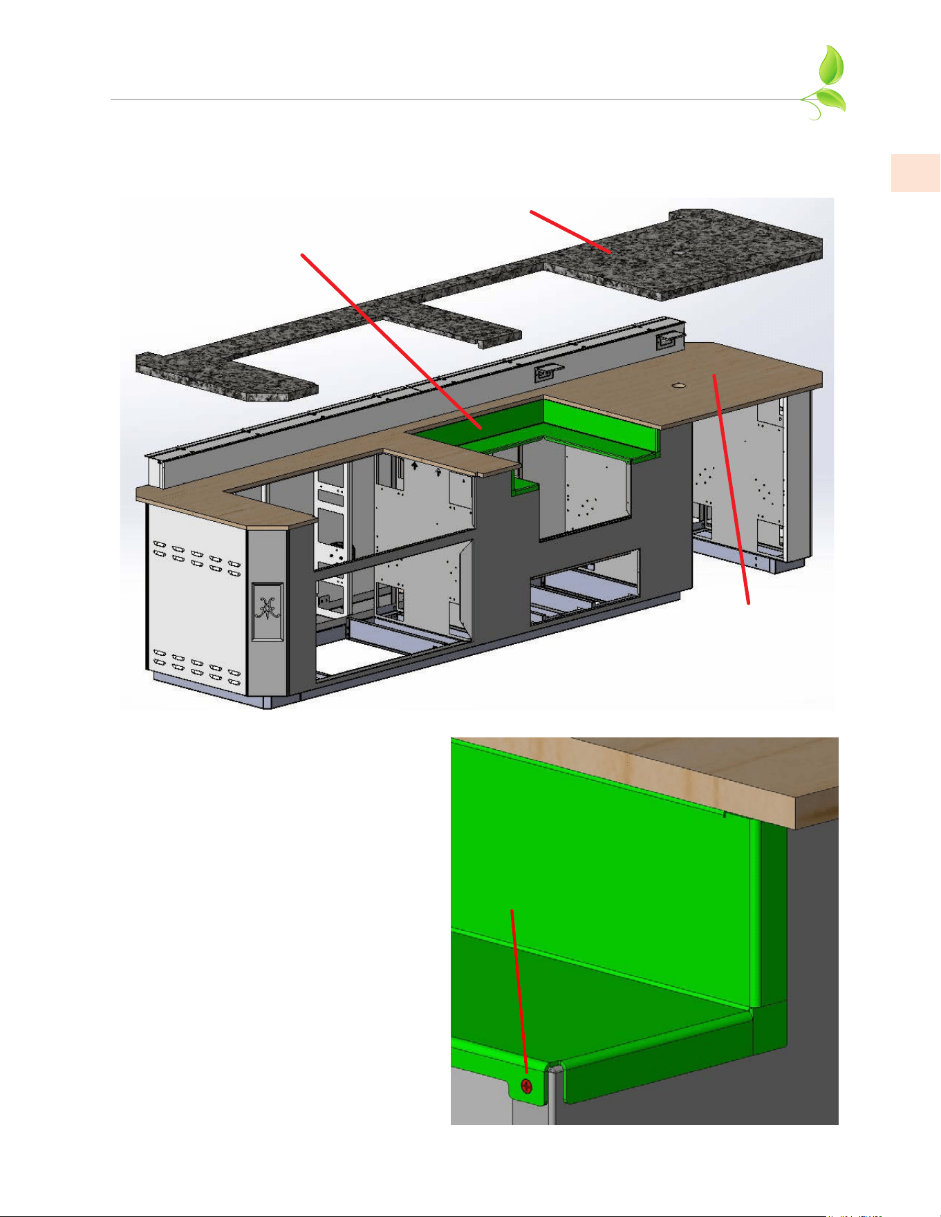
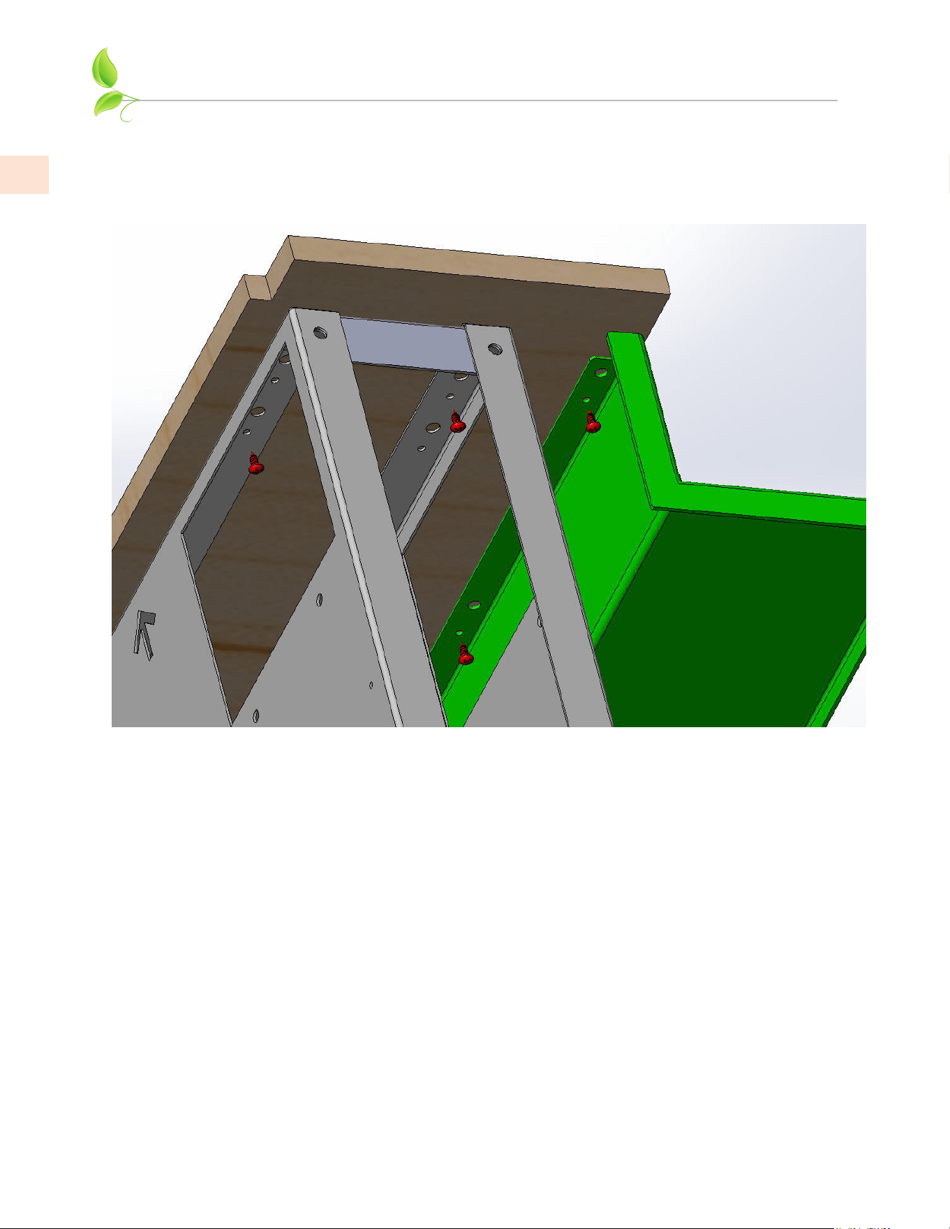
1. The Outdoor Living Suite for Kamado Grill has
a large crossmember which must be installed
before the top and alcove can be installed.
Note the “L” stamped into the crossmember for
correct orientation.
2. Attach crossmember by tucking under the flange
of the front panel, and using 4 each 1/4-20 x 1/2”
hex bolts where needed. Access is from the other
side of the adjacent walls.
©2023 Hestan Commercial Corporation
34
EN
APPENDIX - KAMADO GRILL SUITES
(continued)
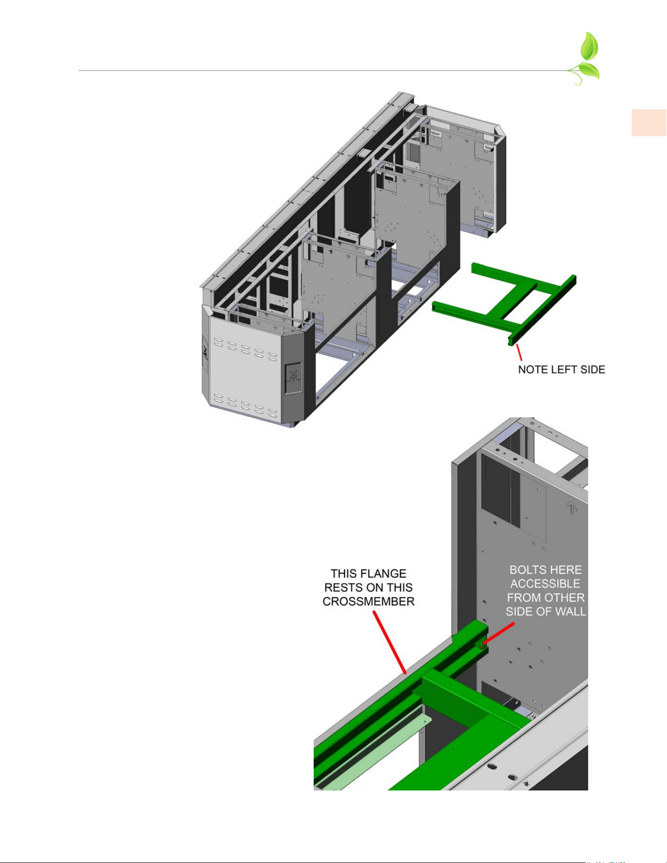
3. This cutaway view shows
additional fastener locations for the
crossmember. Note the “L” for left
side. Tighten all these bolts.
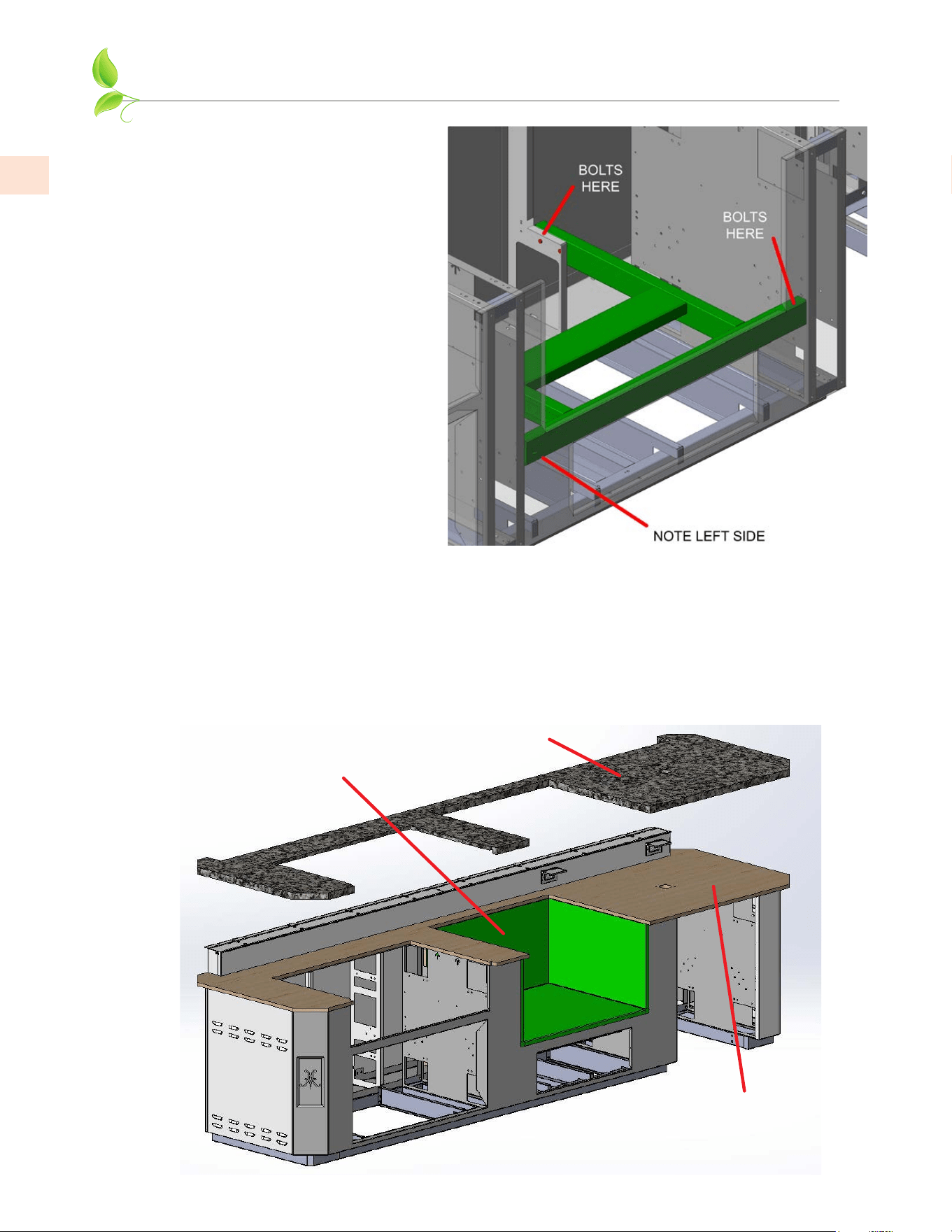
KAMADO GRILL
ALCOVE
PLYWOOD
STONE
4. The Outdoor Living Suite for Kamado Grill features a deep alcove for the appliance which must be
set in place as shown below, then the plywood sub-structure must be secured, then the large stone
countertop. Get assistance from another person to help lift the top and position correctly.
Use coated or stainless steel 1/2” long wood screws where needed to secure the vertical walls
and alcove to the underside of the plywood, using the small holes provided (similar to step 3 on
pg. 32). Tighten any remaining bolts underneath and return to step 5 on pg. 18 to complete the
procedure.
©2023 Hestan Commercial Corporation
35
EN
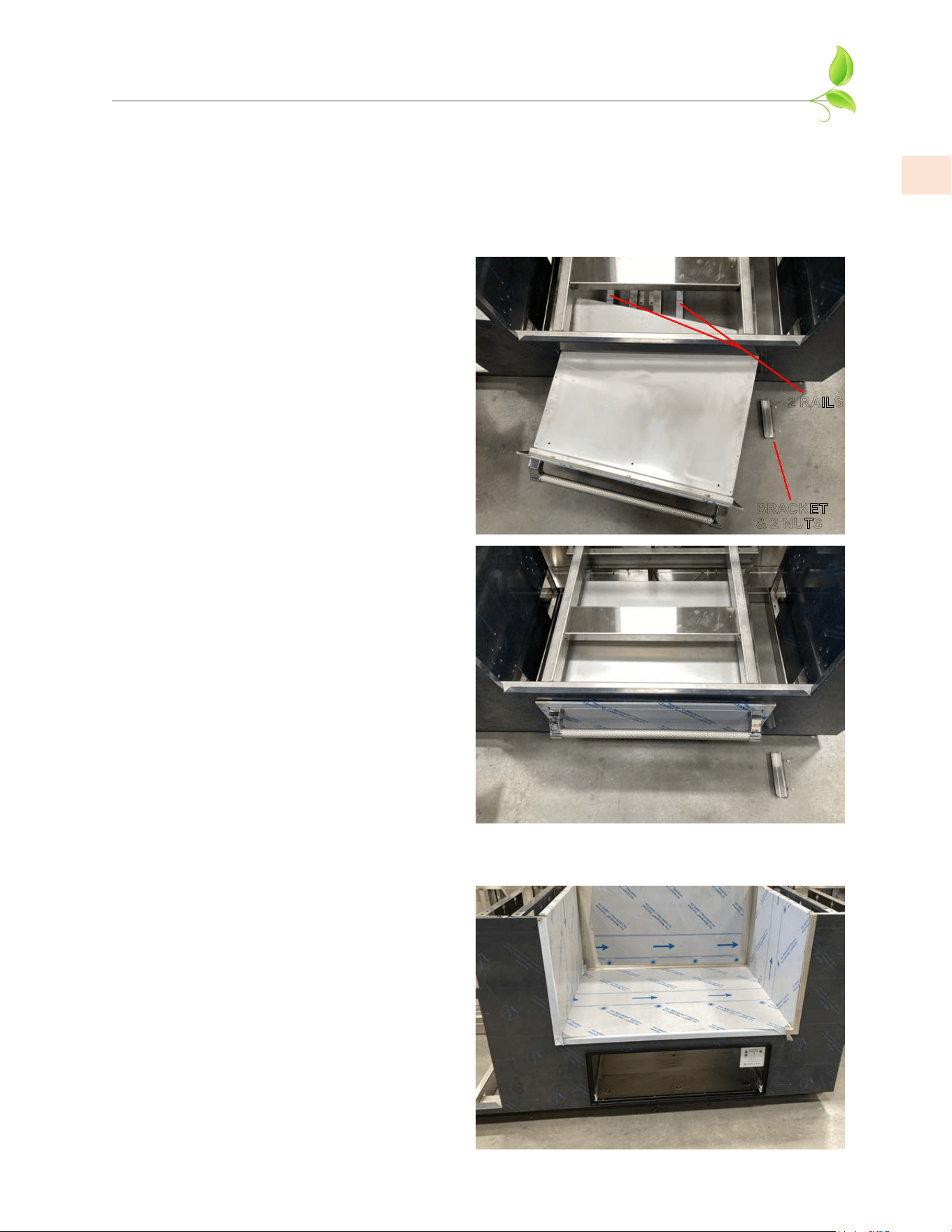
APPENDIX - WARMING DRAWER INSTALLATION
FOR POWER BURNER / KAMADO SUITES ONLY
The opening below the alcove for Power Burner / Kamado can accommodate a Hestan 30” storage
drawer (AGSR
30
) or a Hestan Outdoor Warming Drawer (GWD
30
). Access for installation is much
easier if the alcove and countertop have not been installed yet.
1. If installing the AGSR
30
storage drawer,
there are 2 support rails which were pre-
installed at the factory. These rails remain
in place. There are mounting brackets on
the left and right sides of the opening.
Reach inside the suite and remove one of
the brackets by removing the small nuts.
Place the drawer in the opening at an
angle as shown, then push all the way in.
BRACKET
& 2 NUTS
2 RAILS
2. With the drawer now fully inserted, re-
install the side bracket you removed in
step 1. If necessary, slide out and remove
the drawer box so you can gain access to
the mounting holes inside the drawer case
and secure to those side brackets with
four #10 sheetmetal screws (not included).
For further details about the drawer box
removal and re-installation, see the manual
which came with it.
3. If installing the GWD
30
warming drawer,
the 2 support rails and side brackets
mentioned in step 1 above must be
removed and discarded. Route the power
cord into the opening so you can plug it
into one of the outlets inside the suite.
Place the warming drawer in the opening
and push all the way in. Secure the black
face-frame to the suite using 4 screws
(supplied with the warming drawer) in
each corner of the frame.
Note: In this photo, the drawer box was
removed for clarity.
AGSRAGSR
3030
INSTALLATION INSTALLATION
GWDGWD
3030
INSTALLATION INSTALLATION
©2023 Hestan Commercial Corporation
36
EN
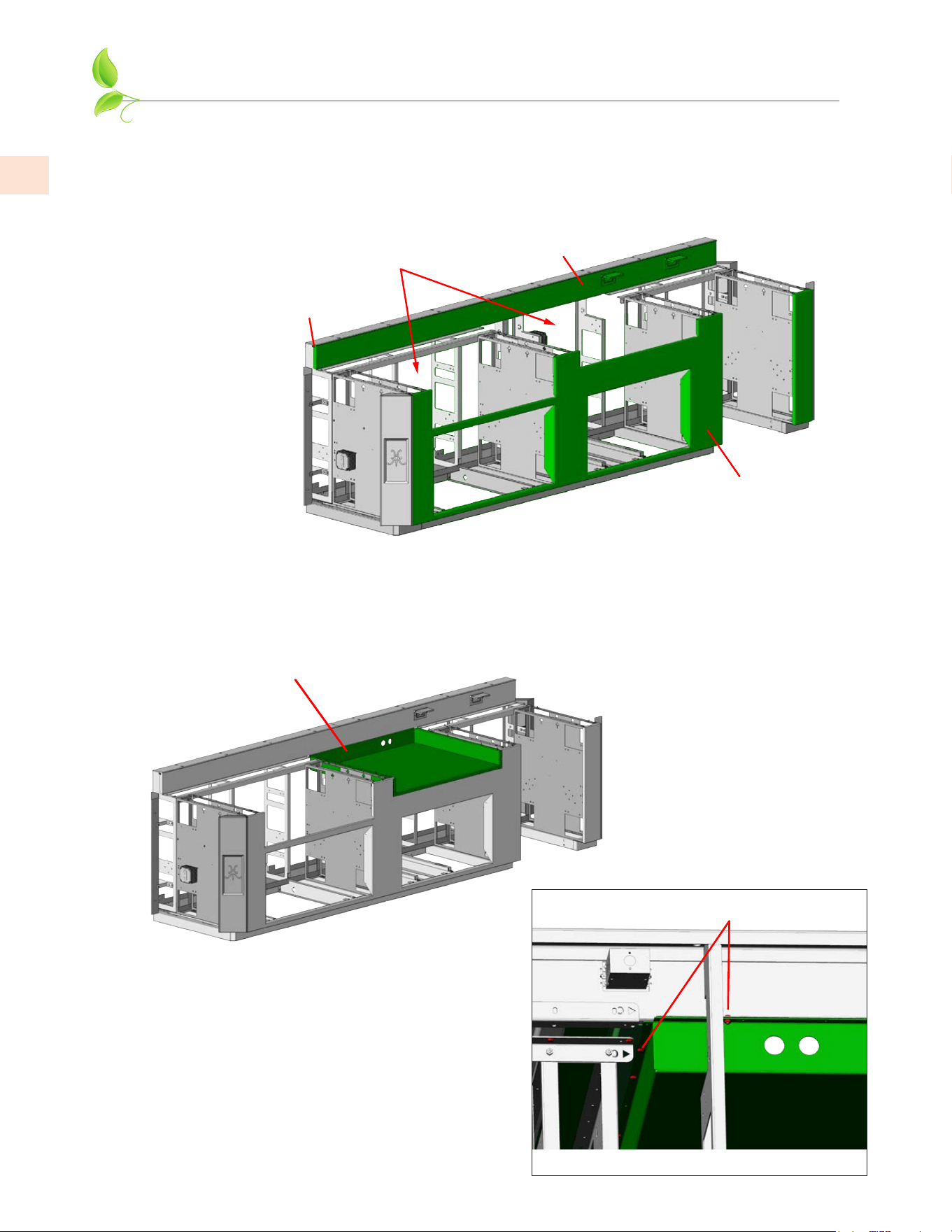
APPENDIX - PIZZA OVEN SUITES WITH BAR
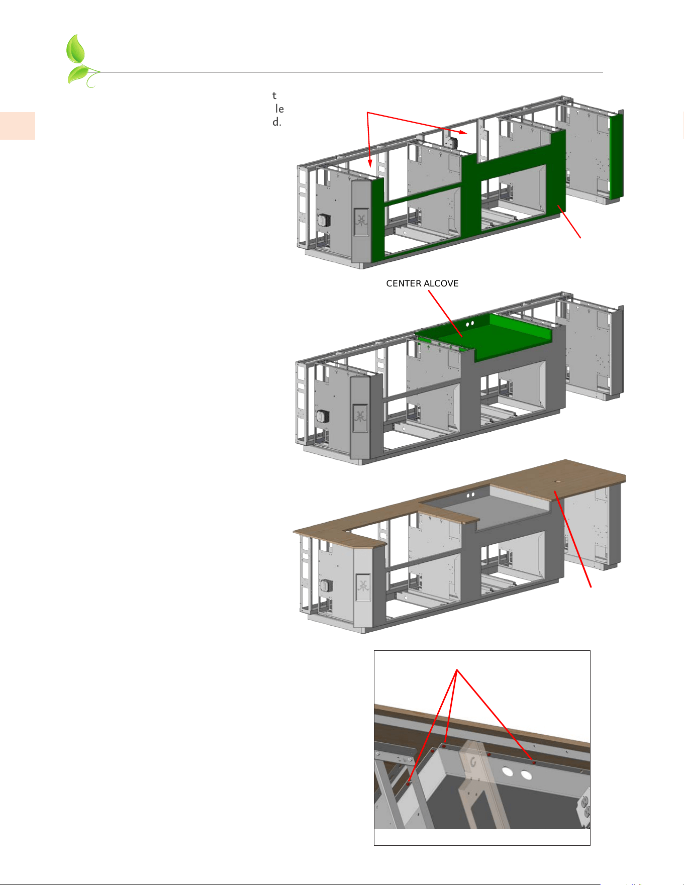
1. The Outdoor Living Suite with Pizza Oven and raised bar will be easier to assemble with the large
rear panels removed.
The bar front panel with electrical outlets is already installed at the factory with screws at each end,
as shown below. Install the front panel per the instructions on pg. 13.
2. The center alcove is shipped loose and must be installed first. Place it in the assembly as shown
below. Loosely install three 1/4-20 x 1/2” long hex bolts and nuts at the rear flange. Do not
tighten yet.
CENTER ALCOVE
ALCOVE BOLTS AT
REAR AND UNDERSIDE
REAR VIEW
LARGE REAR
PANELS REMOVED
BAR FRONT PANEL
w/ OUTLETS
FRONT PANEL
INSTALLED
END
SCREWS
©2023 Hestan Commercial Corporation
37
EN
APPENDIX - PIZZA OVEN SUITES WITH BAR
(continued)
5. The 2 holes at the rear of the alcove
are for running the gas line and
power cord to the pizza oven when
installed. These black plastic plugs
snap into place and will protect
the gas hose and power cord from
damage.
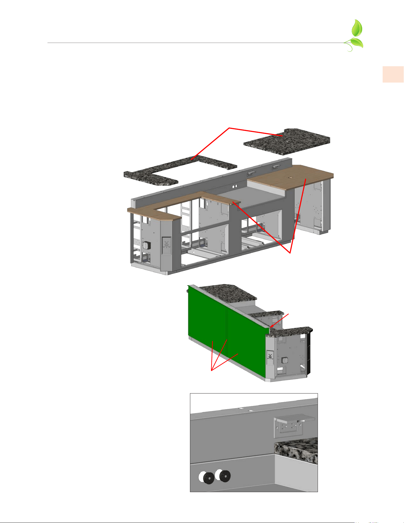
6. Please return to pg. 17 to complete
installation of the bar top.
LEFT & RIGHT
COUNTERTOPS
PLYWOOD
3. Secure the plywood sub-structures as shown below. Use coated or stainless steel 1/2” long
wood screws where needed to secure the vertical walls and alcove to the underside of the
plywood, using the small holes provided (similar to step 3 on pg. 32). Get assistance from
another person to help lift the stone tops and position correctly. Place the stone countertops
and adjust the left/right position of them so each slightly overhangs the alcove walls on
the left and right faces. When you are satisfied with the position of all items, tighten all
remaining screws, nuts and bolts at the underside and rear, and return to step 5 on pg. 18 to
complete the procedure for the top.
REAR PANELS &
CENTER STRIP
END
SCREWS
4. You may now reinstall the large rear
panels and center strip. Secure
with the screws on each end. The
panels will be further secured when
you install the bar top and footrail.
©2023 Hestan Commercial Corporation
38
EN
APPENDIX - PIZZA OVEN SUITES WITHOUT BAR
1. The Outdoor Living Suite without
raised bar will be easier to assemble
with the large rear panels removed.
Install the front panel per the
instructions on pg. 13.
1/2” WOOD SCREWS
REAR VIEW
2. The center alcove is shipped
loose and must be installed first.
Place it in the assembly as shown
below. There are no fasteners to
install yet.
CENTER ALCOVE
LARGE REAR
PANELS REMOVED
FRONT PANEL
INSTALLED
PLYWOOD
3. Place the plywood sub-structure
as shown. Adjust the left/
right position of the plywood
to leave space for the stone to
slightly overhang the alcove walls
(further described in step 5).
4. From below, use coated or stainless steel
1/2” long wood screws where needed to
secure the alcove to the underside of the
plywood, using the small holes provided
(similar to step 3 on pg. 32).
©2023 Hestan Commercial Corporation
39
EN
APPENDIX - PIZZA OVEN SUITES WITHOUT BAR
(continued)
7. The 2 holes at the rear of the alcove
are for running the gas line and
power cord to the pizza oven when
installed. These black plastic plugs
snap into place and will protect
the gas hose and power cord from
damage.
8. Please return to pg. 19 to complete
installation.
5. Slide the plywood forward a few
inches so you can install the rear
panels and center strip as shown.
There are bolts across the top, and
screws on the ends.
Now slide the plywood back so the
rear faces are flush. Check the left/
right position of the plywood again
as you did in step 3. When you
are satisfied with the position of
all items, install all remaining 1/2”
long wood screws where needed
underneath the plywood and vertical
structural members of the suite.
REAR PANELS &
CENTER STRIP
END
SCREWS
TOP
BOLTS
SLIDE PLYWOOD
FORWARD
6. Get assistance from another
person to help lift the stone top
and position correctly. Adjust
the left/right position so the
stone slightly overhangs the
alcove walls on the left and right
faces. Return to step 5 on pg. 18
to complete the procedure for
the top.
STONE COUNTERTOP

©2023 Hestan Commercial Corporation
40
EN
SERVICE
All warranty and non-warranty repairs should be performed by qualified service personnel. To locate an authorized
service agent in your area, contact your Hestan dealer, local representative, or the manufacturer. Before you call, please
have the model number information ready. This information is shown on a sticker affixed to one of the inside vertical
surfaces of your product.
Hestan Commercial Corporation
3375 E. La Palma Avenue
Anaheim, CA 92806
(888) 905-7463
PARTS LIST
Please visit the Hestan website to access the parts list for your Hestan Outdoor product:
www.hestanoutdoor.com.www.hestanoutdoor.com.
LIMITED WARRANTY
WHAT THIS LIMITED WARRANTY COVERSWHAT THIS LIMITED WARRANTY COVERS
Hestan Commercial Corporation (“HCC”) warrants to the original consumer purchaser of a Hestan outdoor product (the “Product”)
from an HCC authorized dealer that the Product is free from defective materials or workmanship for a period of one (1) year from
the date of original retail purchase or closing date for new construction, whichever period is longer (“Limited Warranty Period”).
HCC agrees to repair or replace, at HCC’s sole option, any part or component of the Product that fails due to defective materials or
workmanship during the Limited Warranty Period. This Limited Warranty is not transferable and does not extend to anyone beyond
the original consumer purchaser (“Purchaser”). This Limited Warranty is valid only on Products purchased and received from an HCC
authorized dealer in the fifty United States, the District of Columbia and Canada. This Limited Warranty applies only to Products in
non-commercial use and does not extend to Products used in commercial applications.
HOW TO OBTAIN WARRANTY SERVICEHOW TO OBTAIN WARRANTY SERVICE
If the Product fails during the Limited Warranty Period for reasons covered by this Limited Warranty, the Purchaser must immediately
contact the dealer from whom the Product was purchased or HCC at 888.905.7463.
Purchaser is responsible for making the Product reasonably accessible for service or for paying the cost to make the Product
reasonably accessible for service. Service is to be provided during normal business hours of the authorized Hestan Commercial
Service Provider. To the extent Purchaser requests service outside of the normal business hours of the authorized Hestan Commercial
Service Provider, Purchaser will pay the difference between regular rates and overtime or premium rates. Purchaser is required to pay
all travel costs for travel beyond 50 miles (one way) from the nearest authorized Hestan Commercial Service Provider.
WHAT THIS LIMITED WARRANTY DOES NOT COVER:WHAT THIS LIMITED WARRANTY DOES NOT COVER:
This Limited Warranty does not cover and HCC will not be responsible for and will not pay for: damage to or defects in any Product
not purchased from an HCC authorized dealer; color variations in color finishes or other cosmetic damage; failure or damage from
abuse, misuse, accident, fire, natural disaster, commercial use of the Product, or loss of electrical power or gas supply to the Product;
damage from alteration, improper installation, or improper operation of the Product; damage from improper or unauthorized repair
or replacement of any part or component of the Product; damage from service by someone other than an authorized agent or
representative of the Hestan Commercial Service Network; normal wear and tear; damage from exposure of the Product to a corrosive
atmosphere containing chlorine, fluorine, or any other damaging chemicals; exposure to a salt water environment; damage resulting
from the failure to provide normal care and maintenance to the Product; damage HCC was not notified of within the Limited
Warranty Period; and incidental and consequential damages caused by any defective material or workmanship.
ARBITRATION:ARBITRATION:
This Limited Warranty is governed by the Federal Arbitration Act. Any dispute between Purchaser and HCC regarding or related
to the Product or to this Limited Warranty shall be resolved by binding arbitration only on an individual basis with Purchaser.
Arbitration will be conducted by the American Arbitration Association (“AAA”) in accordance with its Consumer Arbitration Rules or
by JAMS. The arbitration hearing shall be before one arbitrator appointed by the AAA or JAMS. The arbitrator shall not conduct class
arbitration and Purchaser shall not bring any claims against HCC in a representative capacity on behalf of others.

©2023 Hestan Commercial Corporation
41
EN
LIMITATION OF LIABILITY:LIMITATION OF LIABILITY:
This Limited Warranty is the final, complete and exclusive agreement between HCC and Purchaser regarding the Product.
THERE ARE NO EXPRESS WARRANTIES OTHER THAN THOSE LISTED AND DESCRIBED ABOVE. NO WARRANTIES THERE ARE NO EXPRESS WARRANTIES OTHER THAN THOSE LISTED AND DESCRIBED ABOVE. NO WARRANTIES
WHETHER EXPRESS OR IMPLIED, INCLUDING, BUT NOT LIMITED TO, ANY IMPLIED WARRANTIES OF MERCHANTABILITY WHETHER EXPRESS OR IMPLIED, INCLUDING, BUT NOT LIMITED TO, ANY IMPLIED WARRANTIES OF MERCHANTABILITY
OR FITNESS FOR A PARTICULAR PURPOSE SHALL APPLY AFTER THE LIMITED WARRANTY PERIOD STATED ABOVE. NO OR FITNESS FOR A PARTICULAR PURPOSE SHALL APPLY AFTER THE LIMITED WARRANTY PERIOD STATED ABOVE. NO
OTHER EXPRESS WARRANTY OR GUARANTY GIVEN BY ANY PERSON, FIRM OR CORPORATION WITH RESPECT TO THIS OTHER EXPRESS WARRANTY OR GUARANTY GIVEN BY ANY PERSON, FIRM OR CORPORATION WITH RESPECT TO THIS
PRODUCT SHALL BE BINDING ON HCC. HCC ASSUMES NO RESPONSIBILITY THAT THE PRODUCT WILL BE FIT FOR ANY PRODUCT SHALL BE BINDING ON HCC. HCC ASSUMES NO RESPONSIBILITY THAT THE PRODUCT WILL BE FIT FOR ANY
PARTICULAR PURPOSE, EXCEPT AS OTHERWISE PROVIDED BY APPLICABLE LAW.PARTICULAR PURPOSE, EXCEPT AS OTHERWISE PROVIDED BY APPLICABLE LAW.
HCC SHALL NOT BE LIABLE FOR LOSS OF REVENUE OR PROFITS, FAILURE TO REALIZE SAVINGS OR OTHER BENEFITS, HCC SHALL NOT BE LIABLE FOR LOSS OF REVENUE OR PROFITS, FAILURE TO REALIZE SAVINGS OR OTHER BENEFITS,
OR ANY OTHER SPECIAL, INCIDENTAL OR CONSEQUENTIAL DAMAGES CAUSED BY THE USE, MISUSE OR INABILITY TO OR ANY OTHER SPECIAL, INCIDENTAL OR CONSEQUENTIAL DAMAGES CAUSED BY THE USE, MISUSE OR INABILITY TO
USE THE PRODUCT, REGARDLESS OF THE LEGAL THEORY ON WHICH THE CLAIM IS BASED, AND EVEN IF HCC HAS BEEN USE THE PRODUCT, REGARDLESS OF THE LEGAL THEORY ON WHICH THE CLAIM IS BASED, AND EVEN IF HCC HAS BEEN
ADVISED OF THE POSSIBILITY OF SUCH DAMAGES. NO RECOVERY OF ANY KIND AGAINST HCC SHALL BE GREATER IN ADVISED OF THE POSSIBILITY OF SUCH DAMAGES. NO RECOVERY OF ANY KIND AGAINST HCC SHALL BE GREATER IN
AMOUNT THAN THE PURCHASE PRICE OF THE PRODUCT. AMOUNT THAN THE PURCHASE PRICE OF THE PRODUCT.
WITHOUT LIMITING THE FOREGOING, YOU ASSUME ALL RISK AND LIABILITY FOR LOSS, DAMAGE OR INJURY TO YOU WITHOUT LIMITING THE FOREGOING, YOU ASSUME ALL RISK AND LIABILITY FOR LOSS, DAMAGE OR INJURY TO YOU
AND YOUR PROPERTY AND TO OTHERS AND THEIR PROPERTY ARISING OUT OF THE USE, MISUSE OR INABILITY TO AND YOUR PROPERTY AND TO OTHERS AND THEIR PROPERTY ARISING OUT OF THE USE, MISUSE OR INABILITY TO
USE THE PRODUCT NOT CAUSED DIRECTLY BY THE NEGLIGENCE OF HCC. THIS LIMITED WARRANTY STATES YOUR USE THE PRODUCT NOT CAUSED DIRECTLY BY THE NEGLIGENCE OF HCC. THIS LIMITED WARRANTY STATES YOUR
EXCLUSIVE REMEDY.EXCLUSIVE REMEDY.
No oral or written representation or commitment given by anyone, including but not limited to, an employee, representative or
agent of HCC will create a warranty or in any way increase the scope of this express Limited One Year Warranty. If there is any
inconsistency between this Limited Warranty and any other agreement or statement included with or relating to the Product, this
Limited Warranty shall govern. If any provision of this Limited Warranty is found invalid or unenforceable, it shall be deemed
modified to the minimum extent necessary to make it enforceable and the remainder of the Limited Warranty shall remain valid and
enforceable according to its terms.
INTERACTION OF LAWS WITH THIS LIMITED WARRANTY:INTERACTION OF LAWS WITH THIS LIMITED WARRANTY:
Some states, provinces or territories may not allow limitations on how long an implied warranty lasts or the exclusion or limitation
of incidental or consequential damages, so the above limitations or exclusions may not apply to you. Some states, provinces or
territories may provide for additional warranty rights and remedies, and the provisions contained in this Limited Warranty are not
intended to limit, modify, take away from, disclaim or exclude any mandatory warranty requirements provided by states, provinces
or territories, including certain implied warranties. This warranty gives you specific legal rights, and you may also have other rights
which vary depending on location.
Any questions about this Limited Warranty may be directed to
Hestan Commercial Corporation at (888) 905-7463
LIMITED WARRANTY
(continued)

©2023 Hestan Commercial Corporation
42
EN
THIS PAGE LEFT INTENTIONALLY BLANK.

©2023 Hestan Commercial Corporation
43
EN
THIS PAGE LEFT INTENTIONALLY BLANK.

Hestan Commercial Corporation
3375 E. La Palma Ave
Anaheim, CA 92806
(888) 905-7463
RETAIN THIS MANUAL FOR FUTURE REFERENCE
©2023 Hestan Commercial Corporation P/N 016178 REV C