OPERATOR’S MANUAL
CLP
For technical assistance or the WATER MAZE dealer nearest you, visit our website at
www.wmaze.com
8.913-970.0 - L02/12/19
WARNING:
This product and accessories may contain a chemical known to the State of
California to cause cancer and birth defects or other reproductive harm.
For more information about this regulation: www.P65Warnings.ca.gov
89139700-14
■ CLP-5024 ■ CLP-7034


3
CONTENTS
8.913-970.0 - L • WATERMAZE CLP 5024/7034
Introduction ..................................................................................................... 5
Unpacking ....................................................................................................... 5
Important Safety Information .......................................................................6-7
Installation Instructions ..............................................................................7, 8
Check List Before Starting ..............................................................................8
Installation View .........................................................................................9-10
Start-up .........................................................................................................11
Operation CLP-5024/7034 .......................................................................11-12
Pressure Switch and Pressure Tank Operation ............................................ 13
Programming Instructions ........................................................................14-15
Valve Location & Function .......................................................................16-17
Operation Views .......................................................................................18-19
Water Panel Installation ................................................................................ 20
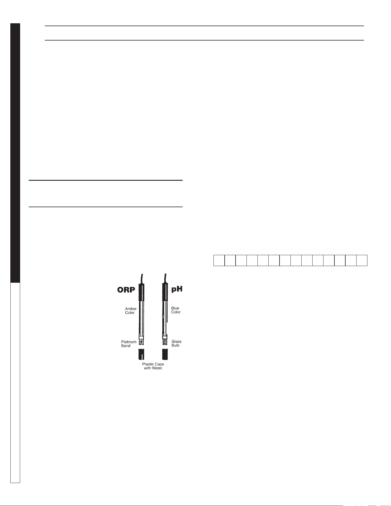
Standard ORP/pH Sensors ...........................................................................21
Sensor Maintenance .....................................................................................22
Troubleshooting - Standard ORP/pH Sensors ..............................................23
VSP20 Metering Pump .................................................................................24
General Maintenance & Service ...................................................................25
Ozone Generator .....................................................................................25-26
Ozone Generator Breakdown Exploded View & Parts List ......................27-28
Chemical Maintenance Program .................................................................. 29
Daily Chemical Maintenance ........................................................................30
Centrifugal Pump Operation & Maintenance ................................................31
CLP-5024 Main Tank Plumbing Exploded View & Parts List ...................32-33
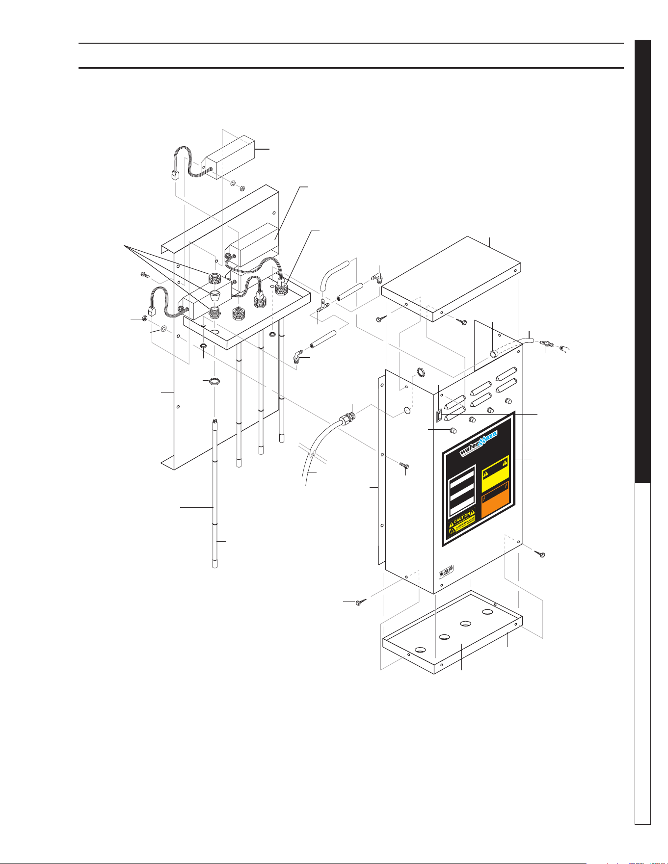
CLP-5024 & 7034 Electrical Box Exploded View & Parts List .................34-36
CLP-5024 Storage Tank Exploded View & Parts List ....................................37
CLP-5024 Pumps Plumbing Exploded View & Parts List ........................38-39
CLP-5024 Plumbing Exploded View and Parts List .................................40-41
CLP-5024 Filter Plumbing Exploded View and Parts List ........................42-43
CLP-5024/7034 Water Panel Breakdown Exploded View & Parts List ....44-45
CLP-7034 Holding Tank Assemblies Exploded View & Parts List ............46-47
CLP-7034 Tank Drain & Oil Skimmer Exploded View & Parts List ...........48-49
CLP-7034 Main Tank Exploded View & Parts List ...................................50-51
CLP-7034 Transfer Pump Exploded View & Parts List .............................52-53

CONTENTS
4
Model Number ____________________________________
Serial Number _____________________________________
Date of Purchase __________________________________
The model and serial numbers will be found on a decal attached
to the machine. You should record both serial number and date of
purchase and keep in a safe place for future reference.
8.913-970.0 - L • WATERMAZE CLP 5024/7034
CLP-7034 Carbon/Multi Media Filter Plumbing Expl. View & Parts List ...54-55
CLP-7034 Flow Meter Plumbing Exploded View & Parts List ..................56-57
CLP-7034 Ozone Pump Exploded View & Parts List ...............................58-59
CLP-7034 Filter Pump Exploded View & Parts List .................................60-61
CLP-7034 Surge Tank/Main Drain Exploded View & Parts List ...............62-63
CLP-7034 Manifold Exploded View & Parts List ......................................64-65
Metering Pump Exploded View & Parts List .................................................66
Transfer Pump Exploded View & Parts List ...................................................67
Filter & Transfer Pumps Exploded View Parts List ...................................68-69
Ozone Pump Exploded View & Parts List .....................................................70
Ozone Pump Exploded View & Parts List .....................................................71
Submersible Sump Pumps Specifi cations ....................................................72
Multi-Media/Carbasorb Filter Exploded View & Parts List ............................73
Carbasorb Filter Exploded View & Parts List ................................................ 74
Multi-Media Filter Exploded View & Parts List .............................................. 75
6 Position Valve Exploded View & Parts List .................................................76
2" Multi-Port Valve Exploded View & Parts List .............................................77
Troubleshooting .......................................................................................78-83
Consumable Parts ........................................................................................84
CLP-7034 Maintenance Schedule ................................................................85
Warranty .......................................................................................................86

8.913-970.0 - L • WATERMAZE CLP 5024/7034
5
WATER TREATMENT SYSTEM
OPERATOR’S MANUAL
INTRODUCTION & SAFETY INFORMATION
INTRODUCTION
Your owner’s manual has been prepared to provide you
with a simple and understandable guide for equipment
operation and maintenance, based on the latest prod-
uct information available at the time of printing. To keep
your machine in top running condition follow the specifi c
maintenance and troubleshooting procedures given in
this manual. When ordering parts please specify model
and serial number.
NOTE: WATER MAZE reserves the right to make
changes at anytime without incurring any obligations.
Owner/User Responsibility:
The owner and/or user must have an understanding
of the manufacturer’s operating instructions and
warnings before using this WATER MAZE machine.
Warning information should be emphasized and
understood. If the operator is not fl uent in English, the
manufacturer’s instructions and warnings shall be read
to and discussed with the operator in the operator’s
native language by the purchaser/owner, making sure
that the operator comprehends its contents.
The owner and/or user must study and maintain the
manufacturers’ instructions for future reference.
SAVE THESE INSTRUCTIONS
This manual should be considered a permanent part
of the machine and should remain with it if machine
is resold.
When ordering parts, please specify model and
serial number. Use only identical replacement parts.
This machine is to be used only by trained operators.
UNPACKING
1. CLP Machine Assembly
2. Sludge Tub
3. Sludge Tub Bag Support
4. Accessory Box
6. Operator’s Manual
NOTE: Any damage to machine or components for
claims against the freight lines.
8.913-970.0 - L • WATERMAZE CLP 5024/7034
OPERATOR’S MANUAL WATER TREATMENT SYSTEM
6
INTRODUCTION & SAFETY INFORMATION
or explosive fl uids such as gasoline, fuel oil, kero-
sene, etc. Do not use in explosive atmospheres.
Pumps should only be used with liquids compatible
with pump component materials. Failure to follow
this warning can result in personal injury and/or
property damage.
AVERTISSEMENT: Les pompes devraient être utili-
sées uniquement avec des liquides compatibles
avec les matériaux des composants des pompes. Le
non-respect des précautions peut mener à des lé-
sions corporelles et/ou des dommages à la propriété.
3. WARNING: Risk of electric shock.
AVERTISSEMENT: Risque de choc électrique
All wiring should be performed by a qualified
electrician.
4. Never make adjustments on the machine while it
is in operation, except for those prescribed in this
manual.
5. The main power must be brought from the circuit
breaker and wired into the electrical box on the CLP.
This line must be run through conduit to protect it
from damage. A power disconnect should be located
next to the machine for maintenance purposes.
6. Before servicing the machine, refer to all the MSDS’s
on the material identifi ed in the wastestream. You
must comply with all warnings and wear all protec-
tive clothing as stated on the MSDS’s.
7. Protect all electrical cords from sharp objects, hot
surfaces, oil, sunlight, and chemicals. Avoid kinking
the cords. Replace or repair damaged or worn cords
immediately. All wiring should be run through conduit.
8. Inlet water temperature must not exceed 85°F.
9. Disconnect the power before servicing this machine.
If the power disconnect is out of sight, lock it in
the open position and tag it to prevent unexpected
application of power.
10. The best insurance against an accident is precaution
and knowledge of the equipment.
11. WATER MAZE is not liable for modifi cations or use
of components not purchased from WATER MAZE.
12. Personal Safety:
a. Wear safety glasses and other applicable
protective clothing at all times when working
on the CLP.
Refer to item #6 under Important Safety
Information.
b. Keep your work area clean, uncluttered and
properly lighted. Replace all unused tools and
equipment.
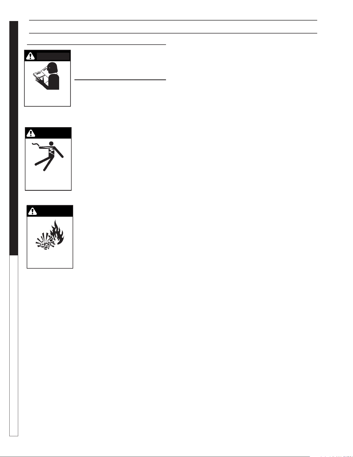
WARNING
RISK OF EXPLOSION:
DO NOT SPRAY
FLAMMABLE LIQUIDS.
WARNING
KEEP WATER SPRAY
AWAY FROM
ELECTRICAL WIRING.
IMPORTANT
SAFETY
INFORMATION
CAUTION: To reduce the risk of
injury, read operating instructions
carefully before using.
ATTENTION: To reduce the risk of
injury, read operating instructions carefully before
using.
1. Read the owner’s manual thor-
oughly. Failure to follow the instruc-
tions will cause a malfunction of the
machine and result in death, serious
injury and/or property damage.
WARNING: Ground system before
connecting to the power supply.
AVERTISSEMENT: Mettre le sys-
tème à la masse avant de le rac-
corder à la source d'alimentation.
WARNING: Wire the system for
correct voltage. See “Electrical”
section of this manual and motor
nameplate.
WARNING: Meet the National
Electrical Code and local codes
for all wiring.
AVERTISSEMENT: Respecter le
Code national de l'électricité et les codes locaux
pour tous les câblages.
WARNING: Follow the wiring instructions in this
manual when connecting the system to the power
lines.
AVERTISSEMENT: Suivre les instructions de câblage
dans le présent manuel au moment de
raccorder le système aux lignes de transport
d'électricité.
WARNING: All wiring must be performed by a quali-
fi ed electrician.
AVERTISSEMENT: Tout le câblage doit être effectué
par un électricien qualifi é.
2. Know the system application, limitations, and poten-
tial hazards.
WARNING: Do not use to pump
concentrations of flammable
WARNING
READ OPERATOR’S
MANUAL THOROUGHLY
PRIOR TO USE.
CAUTION

8.913-970.0 - L • WATERMAZE CLP 5024/7034
7
WATER TREATMENT SYSTEM
OPERATOR’S MANUAL
INSTALLATION INSTRUCTIONS
c. Keep visitors at a safe distance from work area.
d. Make the workshop safe with padlocks and
master switches.
13. Running the system without water will damage the
pumps and will void the warranty.
14. Release all pressure within the system before
servicing any component.
15. Drain all liquids from the component before
servicing.
16. Check hoses for weak or worn conditions before
each use, making certain that all connections are
secure.
17. Periodically inspect pump and system components.
Perform routine maintenance as required.
18. Do not touch an operating motor. Modern motors
are designed to operate at high temperatures.
19. Do not handle a pump or pump motor with wet hands,
when standing on a wet or damp surface, or in water.
20. The pump motors are equipped with an automatic
resetting thermal protector and may restart unex-
pectedly. Tripping is an indication of motor overload-
ing as a result of operating the pumps at low heads
(low discharge restriction), excessively high or low
voltage, inadequate wiring, incorrect motor connec-
tions, or a defective motor or pump.
21. IMPORTANT NOTE: The sump pump is not a
trash pump and is subject to premature failure
unless sump pit baffl ing or additional protection is
provided.
22. Do not stand on the bracket that supports the
Electrical Box, Ozone Generator and the ORP/pH
Controller or on tanks 1 or 2. During installation and
maintenance obtain an OSHA approved ladder.
23. Keep machine from freezing.
24. Do not spray water directly at machine.
INSTALLATION INSTRUCTIONS
1. Because of the nature of the equipment, it is recom-
mended these machines be installed indoors.
2. Locate the CLP on a containment pad to prevent
contamination.
3. Level machine by using shims that will provide ample
support and will not corrode or deteriorate over time.
4. Have a qualifi ed electrician connect the proper
power supply to the electrical control box. It is rec-
ommended that a ground fault circuit interrupter be
installed in the circuit breaker for the CLP.
NOTE: An electrician needs to locate where the
power supply will enter the electrical box and punch
a hole.
5. Install Orp/pH probes into cone bottom tank. Remove
cap and immerse probes into water. Don't let probes
dry. Save cap for future need.
6. Install the angle face dump valve on bottom of cone
bottom tank. Run air hose from angle face dump
valve to air valve assembly. Follow electrical wiring
diagram for air switch wires.
7. Plumb oil decanter barrel.
8. Run ORP/pH pump hoses from pumps to injectors.
9. Run air from air compressor to machine. Use at least
a 3 CFM air compressor with 60-100 psi.
10. Drill holes for 2" bulkheads and install bulkheads.
Connect the sludge tub assembly by placing the
sludge bag support into the sludge tub. Attach the
sludge bag onto the sludge inlet fi tting using the
screw clamp provided.
11. Attach the 2" fl ex hose to the sludge tub by screwing
the hose barbs into the bulkhead connectors, then
attach the 2" fl ex hose to the hose barb using a hose
clamp. The return line should gravity return to the
catch basin. The 2" inlet fl ex hose should connect
between the cone tank discharge valve and the
sludge bag inlet connector.
12. Build the inlet plumbing from the sump pump dis-
charge port (min. 1-1/2" pipe) to the CLP 1-1/2" inlet
line. If the pipe is to be under the concrete, use 2"
pipe. Lower the sump pump into the sump pit.
13. Position the sump pump in the bottom of sump pit.
a. Elevate on a stand or cinder blocks, 6" off the
pit fl oor, to keep pump from sucking in rocks
or other heavy material that may plug pump or
plumbing.
b. Position the pump away from incoming water to
help prevent cavitation.

8.913-970.0 - L • WATERMAZE CLP 5024/7034
OPERATOR’S MANUAL WATER TREATMENT SYSTEM
8
INSTALLATION INSTRUCTIONS
c. Tie a rope or chain to the pump handle and
bring out of the top of the pit for ease of pump
removal. Do not lift pump by power cords or
plumbing. Have a union installed on plumbing at
the top of the pit. Position union so it can easily
be reached and opened for pump removal.
14. The High Level Control Float FS1 (black, normally
open) is the upper fl oat which controls the upper
limits of the sump. It prevents the sump from fl ood-
ing by opening SV1, the rain water solenoid valve.
Float tether length must be a minimum of 2" long.
Position the upper most point of fl oat a few inches
below top of pit. The Fresh Water Make-up Float FS2
(grey, normally closed) controls the lower limits of
the sump. It prevents the sump from running dry by
opening SV2, the fresh water solenoid valve. Turn-on
point for the Fresh Water Make-up Float must be at
least 8" above the suction inlet of sump pump. The
further the water must travel before reaching the
sump, the higher the fl oat must be placed above the
suction intake. On three phase units, a third fl oat is
needed to protect the sump pump from the possibility
of running dry. Position the Low Water Protector Float
#7 (grey, normally closed) 6" above the suction inlet
of sump pump. Single phase sump pumps have a
fl oat built into them.
Floats must travel their complete arc without:
Water going over the top of the pit.
Touching sidewalls or bottom.
The pit running out of water.
Interfering with electrical wiring, plumbing, bottom
or sidewalls of sump, or any object. Attach the
fl oats to the PVC line on the sump pump.
Check to assure the fl oats can operate freely.
(See Installation View.)
15. Run the electrical cords from the sump pump and
fl oats to the electrical junction boxes near the inlet
line and attach wires. If the sump pump and fl oats
are located farther then 20 feet from the electrical
junction boxes, then have an electrician install water
tight junction boxes with conduit and proper sized
wire to extend the electrical connections.
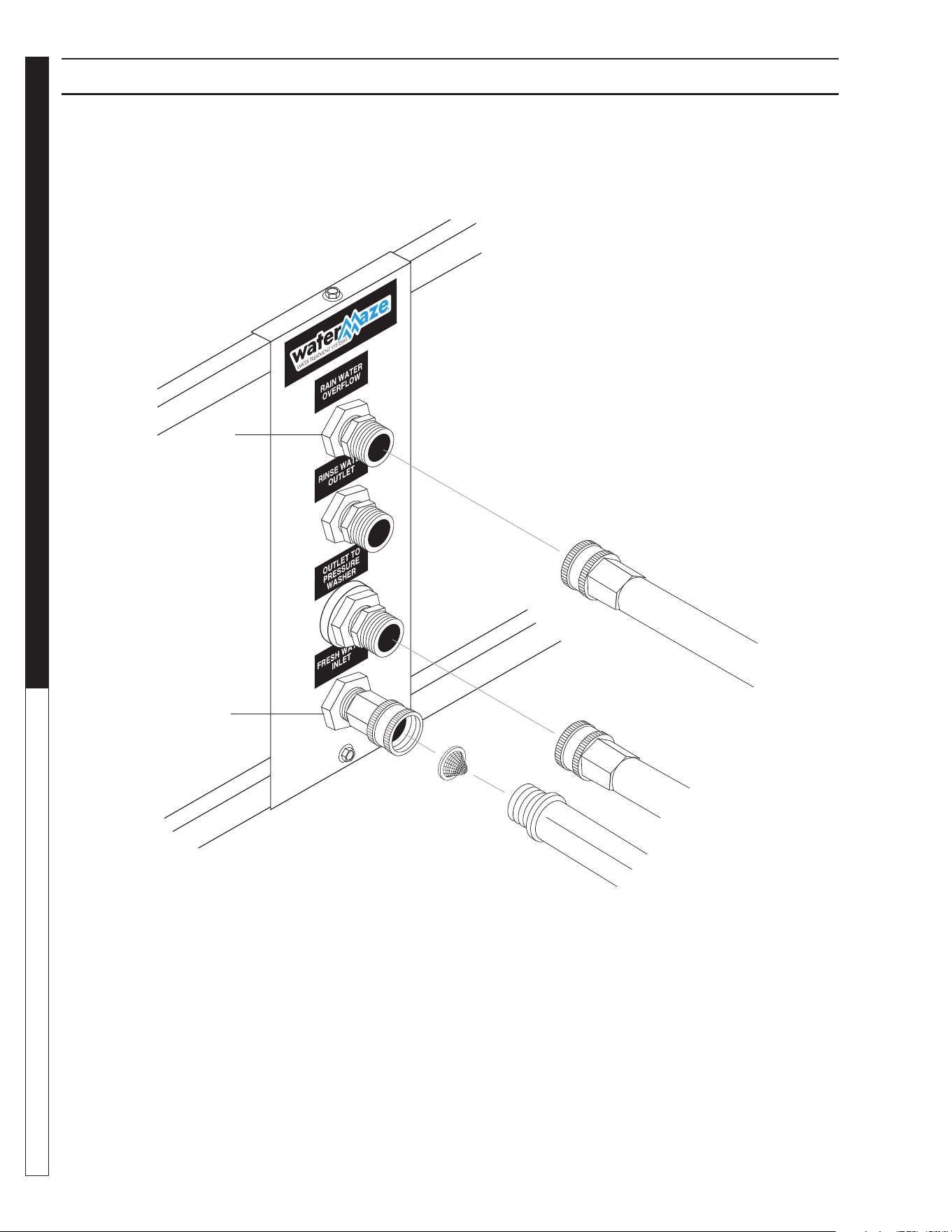
16. Connect the fresh water line (3/4" GHM garden hose
not provided) to the “Fresh Water Inlet” port on the
water panel (see Water Panel Illustration).
17. Connect the “Outlet to Pressure Washers” to your
pressure washer by using a 5/8" garden hose (not
provided). Valve #7 behind the water panel should
remain closed until start-up. You may need a 1" line to
obtain a higher fl ow. If you are going a great distance
or using a lot of elbows, you may not get full fl ow.
18. Connect the “Rain Water Overfl ow” to the sewer or
storage (line not provided). Valve #8 behind the water
panel should remain halfway open.
CAUTION: Discharge Permits are required and
must be obtained before any treated water is
discharged.
ATTENTION: Des permis de déversement sont
requis et doivent être obtenus avant de procéder
au déchargement de toute eau traitée.
19. Connect a hose to “Rinse Water” outlet if it is to be
used. Make sure valve #6 behind the water panel
stays closed until rinse water is needed (hose not
provided).
NOTE: The use of rinse water in a closed loop
system will overfi ll the system and will lead to an
overfl ow situation causing the rainwater overfl ow
valve to open.
20. Run the "Return/Backwash" line back to the collec-
tion pit or fi rst pit where the water will be collected.
This is very important so that there is no stagnant
water when recycling and also to give more set-
ting for the backwash water. If not done properly, it
could void warranty. Run at least a 2" line if above
ground and 3" if below ground. The sludge tub and
oil decanter barrel are plumbed together and run to
the return line. Any back pressure could overfl ow
the sludge tub and/or oil decanter barrel. A separate
return line for the sludge tub and oil decanter barrel
may be needed , the sludge tub can be elevated or
a check valve can be installed.
CHECK LIST
BEFORE STARTING:
Yes No
1. Is inlet line connected from
the sump pump to the inlet
of the machine? ___ ___
2. Is the voltage correct? ___ ___
3. Is the return line connected? ___ ___
4. Is the Fresh Water Make-up
hose connected? ___ ___
5. Is the Outlet to Pressure
Washer hose connected. ___ ___
6. Is the Rainwater Overfl ow
connected? ___ ___
START-UP:
8.913-970.0 - L • WATERMAZE CLP 5024/7034
9
WATER TREATMENT SYSTEM
OPERATOR’S MANUAL
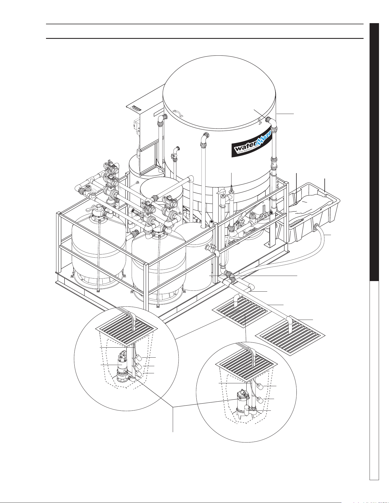
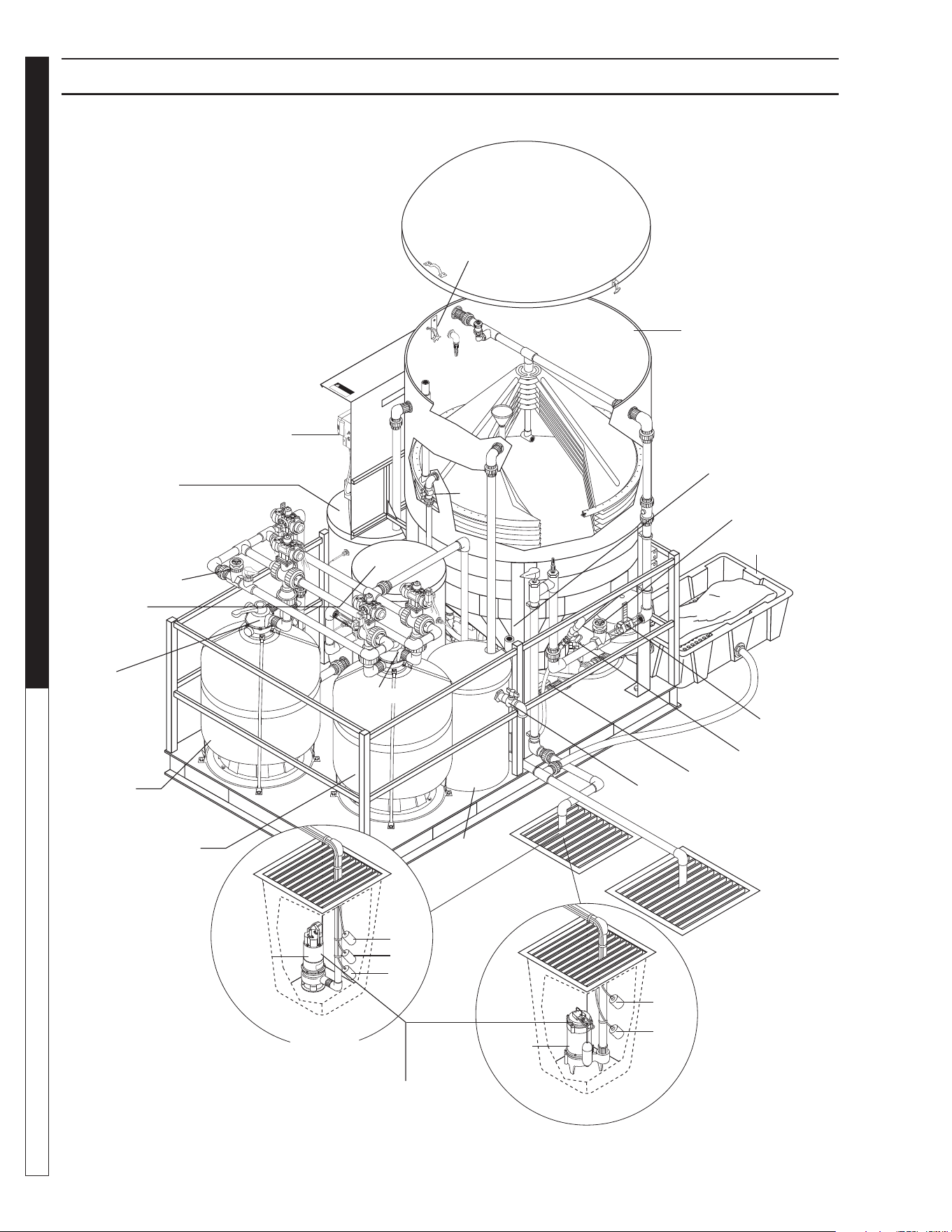
CLP-5024 INSTALLATION VIEW
89139700-3
Inlet
Line
Sump
Pump
FS7
FS2
FS1
Sump Pump
Installation
(3 Phase)
Sump
Pit
FS1
Sump
Pit
FS2
Sump Pump
Installation
Sump
Pump
Inlet
Line
Sludge
Tub
2" Flex
Hose
Catch
Basin
Return
Backwash Line
Inlet
Line
Oil Decanter
Barrel
pH Injector
Cone
Bottom Tank
Inlet
Bag
Support
Sump Pump Not Supplied
with Machine. See
Specifi cation on Page 70.
8.913-970.0 - L • WATERMAZE CLP 5024/7034
OPERATOR’S MANUAL WATER TREATMENT SYSTEM
10
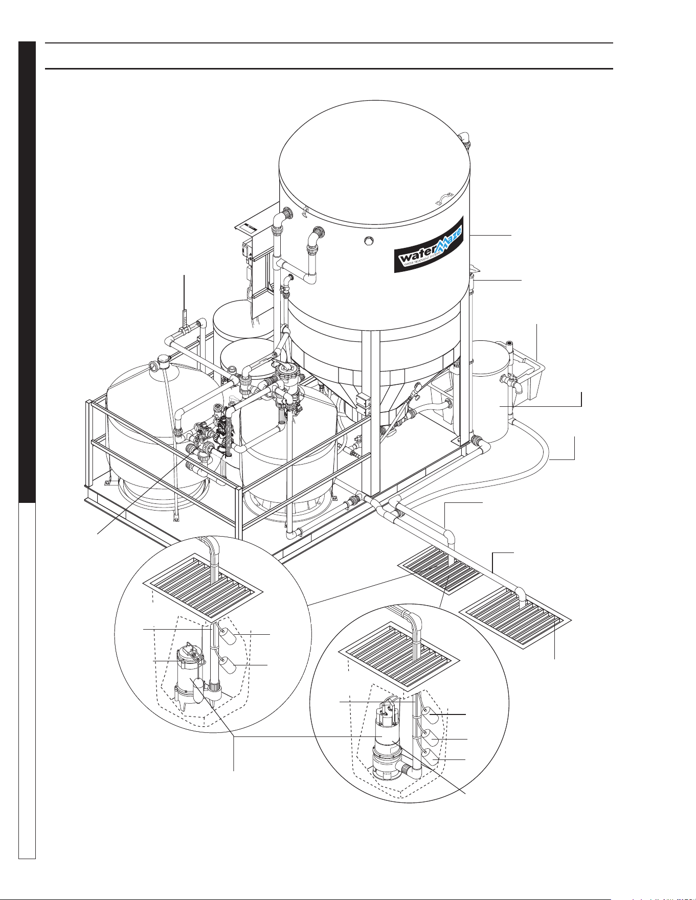
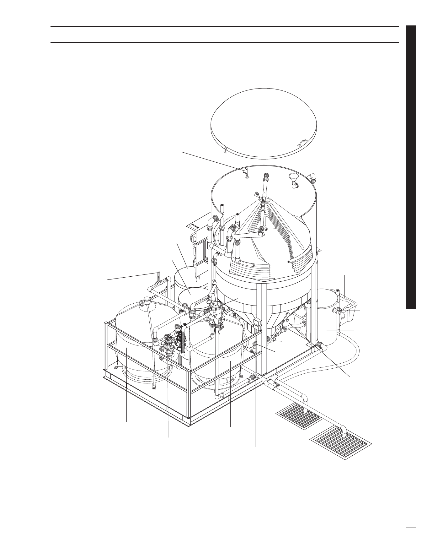
CLP-7034 INSTALLATION VIEW
89139700-21
Sump
Pump
Installation
FS1
FS2
Sump
Pump
Inlet
Line
Sump Pit
Sump
Pump
Installation
(3 Phase)
FS1
FS2
Sump
Pump
Inlet
Line
Sump Pit
FS7
Sludge Tub
2" Flex Hose
Inlet Line
Return/Backwash
Line
Catch Basin
Oil
Decanter
Barrel
Cone Bottom Tank
Inlet
Flow Meter
3 Way
Ball Valve
Assembly
Sump Pump Not Supplied
with Machine. See
Specifi cation on Page 70.

8.913-970.0 - L • WATERMAZE CLP 5024/7034
11
WATER TREATMENT SYSTEM
OPERATOR’S MANUAL
START-UP INSTRUCTIONS
• Make sure that the CLP is level.
• Turn on the Fresh Water Makeup hose.
• After checking for proper power supply voltage,
turn on the circuit breaker to the CLP Machine.
NOTE: Make sure all switches are turned ”OFF”.
• Fill the sump pit with water, and check that the water
level does not drop, which would indicate the pit is
not sealed.
• Turn the sump pump switch to the ON position. The
sump pump lamp will illuminate if sump pump is
operating. (NOTE: the pump has an internally oper-
ated fl oat for low water on single phase only. The
sump pump should fi ll the cone bottom tank with
water. FS3 in tank 1 will shut off the sump in the up
position).
• Adjust the fl ow of water into the CLP using valve
#1 by reading the indicator marks on the inlet fl ow
meter. Set fl ow 2-4 GPM above demand.
• The ozone genertor is programmed to run from 11:00
p.m. to 4:00 a.m. every night. If more ozone is needed
during the day time hours, program Ozone 2 and
Ozone 3 on the PLC to the desired times needed.
• Turn the fi lter pump switch to the ON position. Tank
#2 should fi ll and FS5 will turn off the fi lter pump
when in the up position. The fi lter pump lamp will
illuminate when pump is in operation.
• Adjust valve #10 so that the fi lter fl ow meter has the
same or 2 GPM lower fl ow rate than the inlet GPM
fl ow rate.
• Turn the transfer pump switch to the ON position.
The pump should pressurize and shut off. NOTE:
When the pump is put into operation the pressure
switch may need to be adjusted. See inside cover
of pressure switch for adjustment instructions. The
2 HP pump is set at 20 PSI ON and 40 PSI OFF.
The transfer pump lamp will illuminate when pump
is operating.
• Turn the ozone pump switch to the ON position.
• Check to ensure the oil skimmer is adjusted properly.
Adjust if needed by screwing the funnel up or down,
or angling the pipe to allow a small amount of water
to free fl ow. If oil starts to build up on top of the cone
tank, adjust the skimmer to allow increased fl ow.
NOTE: Only adjust the oil skimmer when the sump
pump is running.
• Place the ORP/pH probes in the bracket inside the
CLP tank. Remove the liquid fi lled cap on the end of
the probes and place them in the bracket. Make sure
the tank is full of water and the probes are kept wet.
Run the connector through the hole in the tank wall
near the bracket and attach the connectors to the
controller. The connector with the white tag near it
is the ORP and is connected to the top stud on the
controller. The other is the pH and is connected to
the bottom stud on the controller.
• Look over entire machine for leaks. The machine
was hydrostatically tested at the factory but may
have been damaged in shipment.
• Program the AMC controller (CLP-7034).
• Turn the ozone generator ON/OFF switch ON.
• Set ozone generator for proper air fl ow.
• Turn ORP/pH controller switch ON.
• Turn ORP/pH feed pumps ON.
• Adjust valves per instructions (See Standard Orp/
pH Controller pages).
OPERATION: CLP-5024/7034
The CLP-5024/7034 are a fully automatic, self-contained
wash water recycling system suitable for treating waste-
water generated from cleaning machinery and equip-
ment. They are designed to separate free oil/greases
and dirt.
At the heart of the automated system is an automatic
maintenance controller (AMC). The AMC provides the
benefi ts of reliability and versatility to control numerous
functions. The AMC controls pump operations, machine
mode light display, fi lter status, backwash requirements,
recirculation, ozone injection, and sludge dumping.
Filter Mode
In a typical operation, wastewater is gravity fed from a
wash pad catch basin to a sump pit (preventing large
solids from entering the sump pump). Water resides in
the sump pump pit until Tank #1 requires water. On Tank
#1's demand, wastewater is pumped into the cone bot-
tom tank. In the cone bottom tank the following occurs:
• Wastewater exits the tank by passing through
a series of corrugated coalescing cones. These
cones slow the fl ow of water (velocity drop) allow-
ing the separation and settling of solids. Solids
settle to the bottom of the tank and are later auto-
matically removed (see automatic sludge dump).
The coalescing cones oil attracting properties,
combined with the 55° incline angle, maximizes
free oil/water separation. Free oils are skimmed
from the surface and discharged to a 26 gallon
oil decanter for further separation.
• To control odor and kill bacteria, an ozone pump
recirculates ozonated water through the upper
section of the cone bottom tank.

8.913-970.0 - L • WATERMAZE CLP 5024/7034
OPERATOR’S MANUAL WATER TREATMENT SYSTEM
12
OPERATING INSTRUCTIONS
Water is gravity fed from the 600 gallon tank to Tank #1
and remains there until Tank #2 requires water. When
water is consumed from Tank #2 (by pressure washer,
recirculation or sewer discharge) the fi lter pump circu-
lates water from Tank #1 through the fi lters to Tank #2.
Flow rates through the fi lters can be adjusted up to 30
gallons per minute (GPM). For best results the fl ow rate
should be set to the lowest GPM that still allows the
entire system to operate correctly (the lower fl ow rate
increases wastewater/fi lter contact time and reduces the
fi lters solids loading).
Water remains in Tank #2 until it is either discharged
to the sewer (check your local regulations for limits in
your area), reused by the pressure washer or used for
recirculation of the pits and fi lters (see recirculation
mode). In the event an excess amount of water enters
the system (through rinse water or rain water) water is
automatically discharged from Tank #2 through the rain
water overfl ow solenoid valve to either the sewer or to
a holding tank. If the system's water level becomes too
low (i.e. evaporation, vehicle carry off), a fresh water
make-up solenoid valve feeds fresh water to Tank #2
until proper levels are maintained.
Filters
To ensure optimum filter performance and life, the
multi-media and carbon fi lters must periodically be
backwashed (see automatic backwash mode).
• The multi-media fi lter consists of a blend of sand,
garnet, gravel and anthracite. The media blend is
effi cient in screening out solids to 25-30 microns.
During the recirculation mode, the constant fl ow
through the media fi lter provides a fi nal polish to
the water.
• The carbon fi lter consists of degassed, virgin ac-
tivated carbon. Carbon removes, through absorp-
tion, pesticides, solvents, benzene, diesel fuels,
acetone and other hydrocarbons as well as low
levels of heavy metals.
Automatic Backwash Mode
Backwashing the media fi lters is required to rejuvenate
the fi lter media. Backwashing removes collected materi-
als and disperses the media to eliminate any channeling.
During normal operation of the CLP-5024/7034, the
multi-media fi lter, carbon fi lter or both may become
impacted with fi ltered solids, resulting in pressure head
loss through the fi lters and in poor overall performance.
The CLP-5024/7034 will backwash everyday if it needs
to or not. The multi-media will start backwashing at
midnight for 30 minutes. The CLP will then recover the
water level in Tank #1 and then backwash the carbon
fi lter. The operator cannot use the pressure washer at
that time, so it is important that the program imitates
your schedule. If it doesn't, call factory for assistance in
reprogramming your controller.
To backwash, the affected fi lter is isolated and the fl ow is
reversed via air actuated three way valves. A slip stream
solenoid is activated to allow proper water fl ow (30 GPM
for multi-media valve 20, 15-20 GPM for carbon valve
21) and water is pumped from Tank #1 through the fi lter
by the fi lter pump. This process continues for 30 minutes
and the resulting backwash outfl ow is returned to the
wash pad catch basin.
Once backwashing of the fi rst fi lter is completed the
second fi lter will then be backwashed. At no time will
both fi lters be backwashed at the same time.
Recirculation Mode
The purpose for recirculating the water through the pit
system and the fi lters is to minimize odor, kill bacteria
and provide high quality polished water.
Once each day the CLP will enter a recirculation mode.
This mode consists of two separate stages.
Stage 1: The transfer pump sends water from Tank #2
through the return line to the wash pad catch
basin. To prevent odor and kill bacteria, the
return water is ozonated via a mazzi injector.
Stage 2: Water is recirculated through the fi lter pack.
The transfer pump circulates water from
Tank #2 through a mazzi injector to Tank #1.
From Tank #1 the fi lter pump circulates water
through the fi lters to Tank #2.
Automatic Sludge Dump
During normal operation, the settling properties of the
solids will result in sludge build-up inside the cone bottom
tank cone. This sludge must be periodically removed.
This is accomplished once each day by an automated
sludge dump system.
To dump sludge, an air activated dump valve opens while
simultaneously a water solenoid activates (to stir-up any
impacted material in the bottom of the cone bottom tank)
to allow sludge to fl ow to the sludge collection bag. To
reduce excess water in the sludge bag, the water sole-
noid is only activated for a few seconds. Once the dump
valve closes, the sludge bag is allowed to de-water and
excess water is returned, via gravity feed, to the wash
pad catch basin.
If at any time, the user needs an additional sludge dump, a
manual switch enables the automatic sludge dump cycle.
AUTOMATIC MAINTENANCE
CONTROLLER; 5024, 7034
8.913-970.0 - L • WATERMAZE CLP 5024/7034
13
WATER TREATMENT SYSTEM
OPERATOR’S MANUAL
WARNING: Live electrical
contacts are exposed, so dis-
connect power fi rst and have
work performed by a qualifi ed
electrician.
AVERTISSEMENT: Les con-
tacts électriques sous ten-
sion sont exposés, il faut
donc d'abord débrancher
l'alimentation électrique et confi er le travail à un
électricien qualifi é.
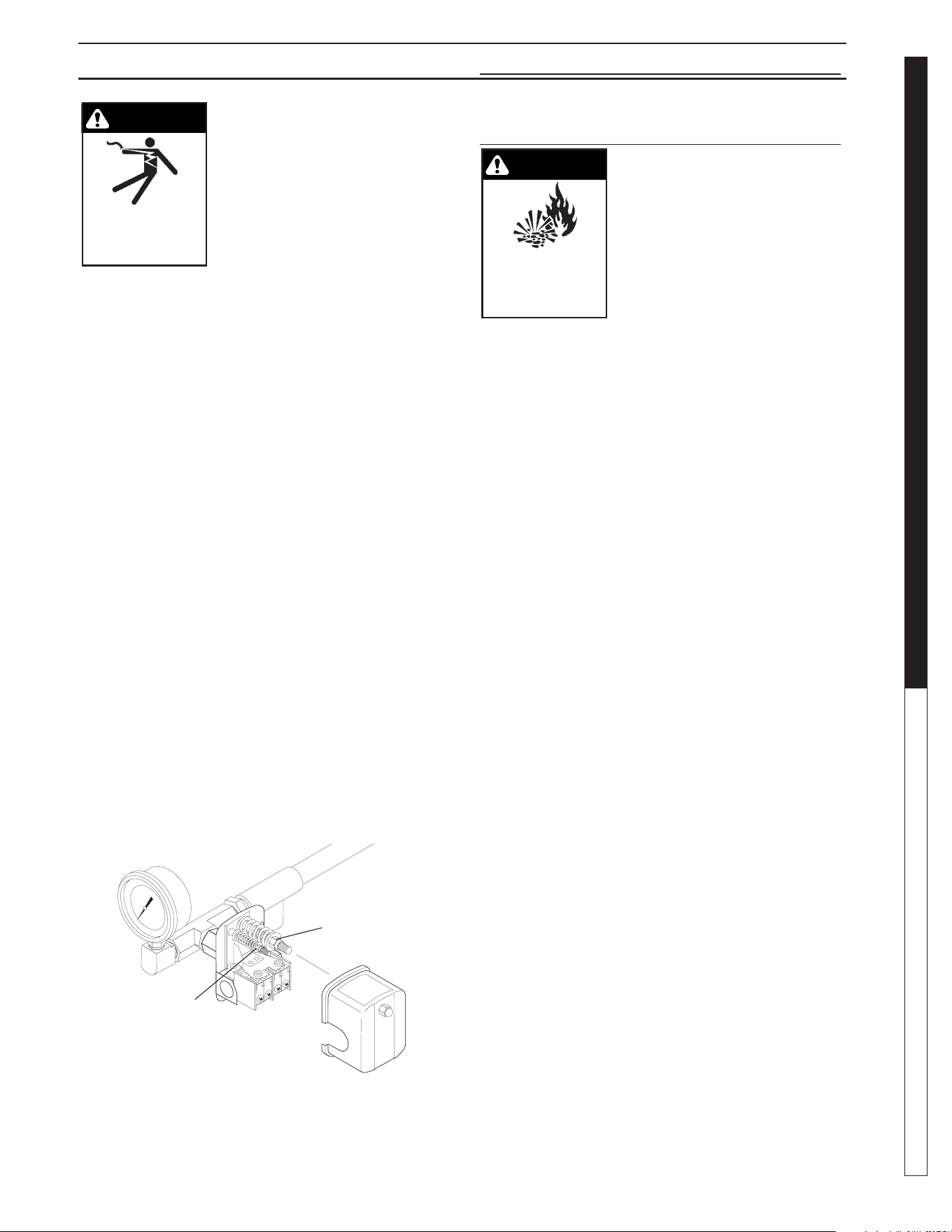
Remove cover of the pump pressure control switch to
allow access to the two nuts used to adjust the pump
operating pressure. The pressure switch on Water
Maze equipment is set at the factory and should not
have to be adjusted at start-up, but will need to be
verifi ed at start up and maintained regularly at least
monthly.
1. The nut on the larger spring in the pump pressure
switch, adjusts the pump cut in (cut on) and pump
cut out (cut off) pressures simultaneously.
2. The nut atop the smaller spring in the pump pres-
sure switch only controls the cut out range and
is used to narrow or widen the gap between the
pump cut in and cut out pressures.
3. To cycle the pump less frequently, the gap should
be as wide as possible while still allowing the
pump to shut off quickly when all outlets are
closed. Adjust the smaller spring to widen the
gap between pump in and out (on and off). 40-
45 PSI (CLP, Rec2-20) or 30 PSI (EC1-300A) is
desirable. Adjusting the larger spring should not
be necessary.
4. When making pressure switch adjustments, make
sure all pump outlets are off or closed, except for
the one outlet valve used to relieve and build pres-
sure while making pressure switch adjustments.
PRESSURE TANK
OPERATION
WARNING! When the tank has
been in service and a change
to a higher pre-charge pressure
is necessary because of a re-
quired change in the pressure
switch setting, failure to follow
instructions below can cause a
rupture or explosion and could
cause serious or fatal personal
injury and/or property damage.
AVERTISSEMENT: Après avoir effectué l'entretien
du réservoir, il est nécessaire de passer à une
pression de précharge supérieure en raison d'un
changement requis du paramètre du pressostat;
le non-respect des directives ci-dessous peut
causer une rupture ou une explosion, et pourrait
causer des lésions corporelles graves ou fatales
et/ou des dommages à la propriété.
• Do not adjust or add pressure if there has been a
loss of air.
• Do not adjust the pre-charge pressure if there is
visible exterior corrosion.
• Do not adjust the pre-charge pressure if there has
been a reduction of the pump cycle time or the
pre-charge pressure compared to its initial setting.
A reduction in pump cycle time can result from
loss of tank corrosion and any re-pressurization
or additional pressure could result in rupture or
explosion.
• Pressure tank pressure is factory set but will have
to be checked regularly (at least monthly). Use
an air pressure (tire) gauge. Before checking air
pressure on the pressure tank, purge all water out
of the tank by turning the pump on and pumping
all water out of the pressure tank.
1. Our transfer pump water systems use a water
pressure tank and water pump with these two
pressure operation ranges:
Cut in (start pumping): 20 PSI
Cut out (stop pumping): 30 PSI (EC1-300A)
Cut out (stop pumping): 40-45 PSI (CLP, REC2-20)
2. Typical factory set air pressure on bladder-type
residential water pressure tanks are shipped from
the factory with a standard pre-charge of:
18 psig for models WX-101 and WX-102
18 psig for models WX-103 and WX-203
18 psig for models WX-205 and WX-350
3. Set the well tank air pressure to 2 PSI below the
pump pressure switch cut-in pressure. This is
usually 18 PSI.
WARNING
RISK OF
EXPLOSION:
FOLLOW
INSTRUCTIONS WHEN
CHANGING PRESSURE
WARNING
RISK OF
ELECTRIC SHOCK: USE
CAUTION
WHEN HANDLING.
PRESSURE SWITCH AND PRESSURE TANK OPERATION
8913970-39
Controls
Cut in/Cut out
Controls
Cut out Range

8.913-970.0 - L • WATERMAZE CLP 5024/7034
OPERATOR’S MANUAL WATER TREATMENT SYSTEM
14
PROGRAMMING INSTRUCTIONS
The heart of the CLP Automatic Maintenance System,
the AMC Controller, has been pre programmed at the fac-
tory with Maintenance Modes described in the Program
Schedule shown below. In order for the CLP wastewater
system to function properly, the controller clock must be
set with the correct time-of-day and date.
Setting the Clock
After the time-of-day and date are set, the Automatic
Maintenance System will automatically control the op-
eration of your CLP and provide daily scheduled mainte-
nance in accordance with the Program Schedule below.
If electrical power is cut from the CLP, the AMC Control-
ler will retain its program for 7 days. If electrical power
is not reconnected within 7 days, then the time-of-day,
month and year must be reset.
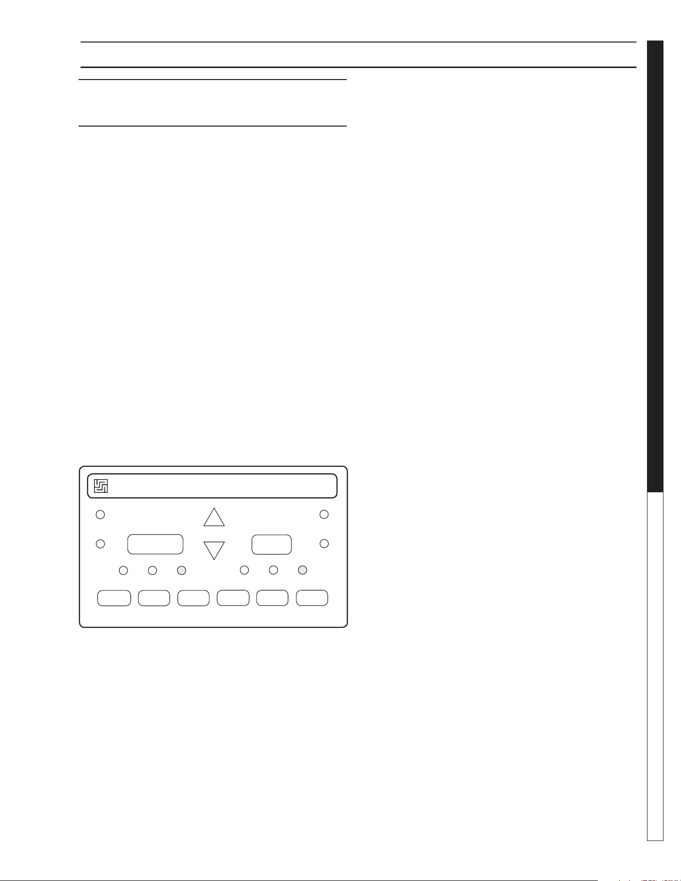
1. Press the ESC key located next to the display win-
dow and under the arrow key pad (see fi gure below).
Pressing the ESC key will access the Parameter
Assignment Menu.
2. Using the up/down arrow keys ▲ or ▼, move the
cursor to highlight ‘Setup’ and press OK to accept.
3. Move the cursor to highlight ‘Clock’ and press OK to
accept.
4. Move the cursor to highlight ‘Set Clock’ and press
OK to accept.
NOTE: When setting time on clock, use only mili-
tary time.
5. Move the cursor to the value wanting to be changed
using the left/right arrow keys or , and change
the value by using the up/down arrow keys ▲ or ▼.
When you are done setting the time and date press
OK to accept your changes.
6. Press ESC three times to exit to the main menu.
Program Schedule
The Automatic Maintenance Controller has been pre-
programmed to the Program Schedule on the next page
with Mode #1 starting at 12:00 midnight and continuing
through all 6 maintenance modes to 4:16 a.m. If needed,
the Mode start time and run times may be changed to
suit a specifi c application. We suggest that you consult
a factory representative prior to making any changes to
the Program Schedule.
VALVE LOCATION &
Mo 10:15
2006-10-13
ESC OK
Program CardParameter Assignment Menu
Arrow
Key Pad
Stop
Program
Setup
Network
Diagnostics
Msg Cong
Start Screen
Clock
LCD
Menu Language
Switch to OP
NTP
Set Clock
S/W Time
Set Clock
Mon. 10:15
YYYY-MM-DD
8.913-970.0 - L • WATERMAZE CLP 5024/7034
15
WATER TREATMENT SYSTEM
OPERATOR’S MANUAL
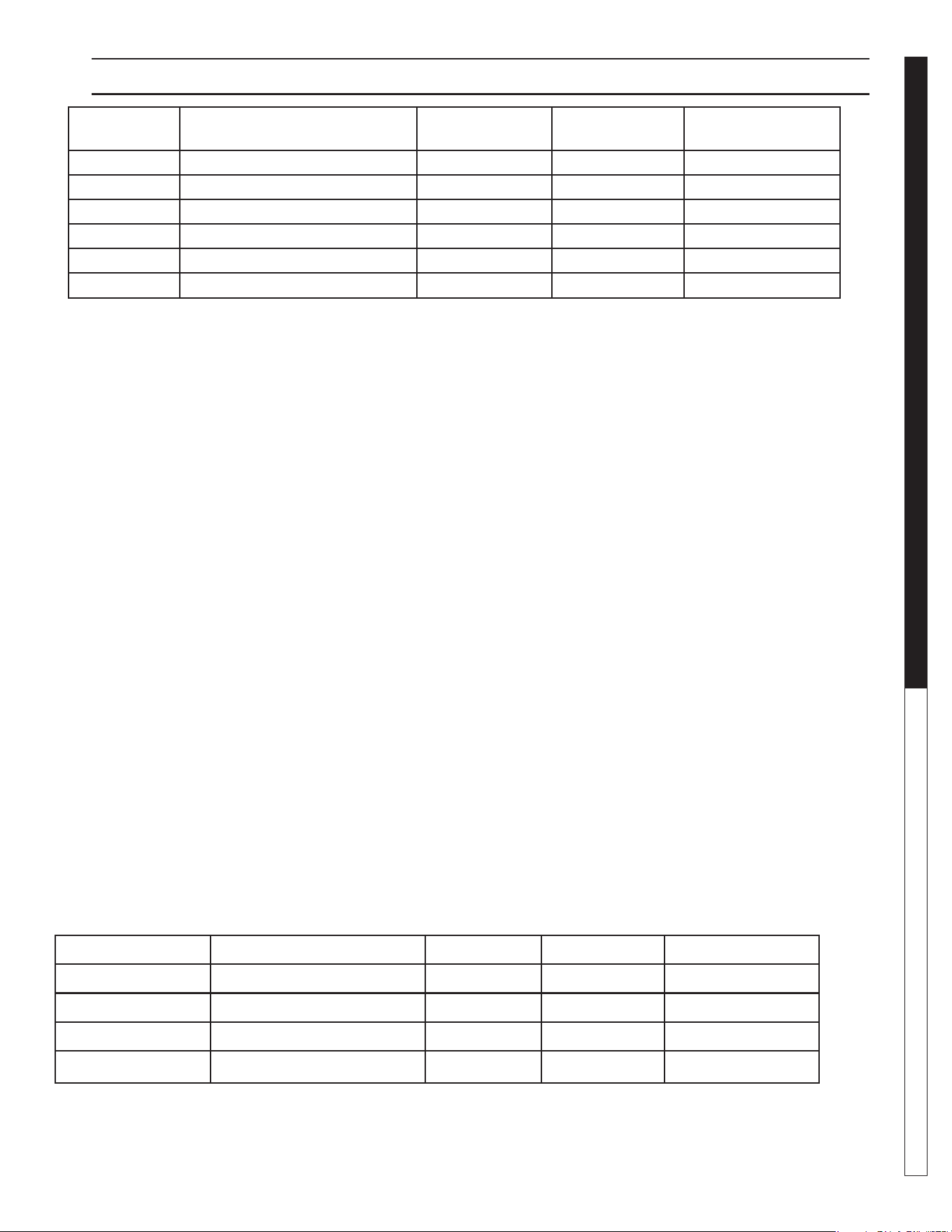
PROGRAMMING INSTRUCTIONS
Maintenance
Mode Description Start Time Run Time Program Name
1 Media Filter Backwash 12:10 a.m. 30 minutes MMB Time 1
2 Carbon Filter Backwash 12:45 a.m. 30 minutes CRB Time 1
3 System Recirculation 1:30 a.m. 1.5 hours SR Time 1
4 Filter Recirculation 3:15 a.m. 1 hour FR Time 1
5 Automatic Sludge Dump 4:16 a.m. 1 minute P Time 1
6 Ozone Circulation 11:00 p.m. 5 hours Oz Time 1
Maintenance Mode
Description Button Button Program Name
1
Media Filter Backwash ESC MM TIme 1
2
Carbon Filter Backwash ESC CRB Time 1
3
System Recirculation ESC SR Time 1
4 Filter Recirculation ESC FR Time 1
▲
▲
▲
▲
Manual Start/Run:
Overriding the automatic maintenance schedule and
manually starting any of the Modes above can be done
in two ways:
1. To manually start and run any of the six maintenance
modes as shown in the Program Schedule above,
reset the AMC time-of-day clock to the start time as
shown in the schedule. For example, to manually
start the Media Filter Backwash cycle, temporarily
reset the AMC clock to 12:00 midnight. Don't forget
to set the clock back to its true time of day.
2. Maintenance Modes 1 through 4 are used by
WaterMaze personnel to test each CLP before it
leaves the factory, these four modes can be manually
started and run by following these instructions.
a. From the date and time screen hit the
left arrow and you'll see "ESC + C" displayed.
b. From the " ESC + C" screen follow the chart
below for the mode you want to test. For example to
start the Media Filter Backwash fi rst hit the "ESC"
button followed by the up arrow (
▲), about a 1/2
second delay between the two. Each mode will run
for 2 minutes to give time to check for proper operation,
set fl ows and etc.

8.913-970.0 - L • WATERMAZE CLP 5024/7034
OPERATOR’S MANUAL WATER TREATMENT SYSTEM
16
VALVE INSTRUCTIONS
FUNCTION:
It is extremely important to know the location and func-
tion of the valves on the CLP. Improper positioning of
the valves can cause overfl ow or damage which could
result in time consuming clean-up and repairs. Study the
section on “Valve Location and Function.”
• Valve 1 - Flow Control Valve
This valve controls the amount of water allowed
into the CLP from the sump pump. Adjust 2-4 gpm
above your demand on the system (See Pages
13, 58).
• Valves 2 & 3 - Ozone Pump
Should be open at all times (See pages 19, 42,
44).
NOTE: Only to be closed when removing or re-
placing the ozone pump.
• Valve 4 - Oil Skimming Bucket
Valve should be closed except when draining
off oil (See pages 13-14).
• Valve 5 - Tank Valve
This valve should be open at all times except when
removing air valve for repair (see pages 13-14).
• Valve 6 - Rinse Water Control Valve
This valve is opened only when rinse water is
needed (See page 44).
• Valve 7 - Outlet to Pressure Washer Valve
After start-up, this valve is left fully open all of
the time. Controls water to the pressure washer
(See page 44).
• Valve 8 - Rain Water Overfl ow Valve
Left open partially. When SV#1 opens, water is
allowed to discharge while still providing water for
the pressure washer (See page 44).
• Valve 9 - Recycle Flow Control Valve
This valve is used to control the volume of
water going back to the collection pit for recycling
through the system when the PLC or AMC acti-
vates the solenoid, SV3, for recycling the system.
Open partially to match fi lter fl ow meter allowing
a smooth fl ow without cycling transfer pump as
much as possible (See pages 46, 66).
• Valve 10 - Filter Flow Control Valve
This valve controls the amount of water allowed
to fl ow through the fi lters. Adjust to the same or
2 gpm below valve #1 (See pages 36, 62).
• Valve 11 & 12 - Filter Control Valve
When set on Filter, this valve allows water to pass
through the fi lter. When set on Backwash, the
water passes through the fi lter in reverse, then
passes back to the catch basin. The air valves
control these valves (See pages 13-14).
• Valve 13
Should be open at all times. Allows pressur-
ized water to fl ush sediment from the cone tank
(See pages 13-14).
• Valve 14

8.913-970.0 - L • WATERMAZE CLP 5024/7034
17
WATER TREATMENT SYSTEM
OPERATOR’S MANUAL
This valve should be open at all times to allow
pressurized water to fl ush out the sludge hose
(See pages 14, 38, 66).
Valve 16
Should be open at all times. Allows fresh water
into tank 2 when SV#2 opens. Valve should be
fully open (See page 44).
Valve 17
In the recirculation mode, this valve is used to
control the volume of water going to tank #1 when
the PLC or AMC opens SV#4. Open partially to
match fi lter fl ow meter allowing a smooth fl ow
without cycling transfer pump as much as possible
(See pages 38, 66).
Valve 20
Should be open partially to control the amount
of water fl ow to backwash the multi-media fi lter
when the PLC or AMC opens SV#7. Set for 30
gpm (See pages 36, 62).
Valve 21
Should be open partially to control the amount of
water fl ow to the backwash carbon fi lter when the
PLC or AMC opens air solenoid valves. Set for
15 gpm (See pages 40, 56).
8.913-970.0 - L • WATERMAZE CLP 5024/7034
OPERATOR’S MANUAL WATER TREATMENT SYSTEM
18
CLP-5024 OPERATION VIEW
WARNING
PRECAUTION/ATT
ENTI
ON
DO NOT STAN
D
OR STEP
ON THIS PLATF
OR
M
WARNING
PRECAUTION/ATTENTION
DO NOT STAND O
R
STEP
ON THIS PLATFORM
89139700-5
Inlet
Line
Sump
Pump
FS7
FS2
FS1
Sump
Pit
FS1
Sump
Pit
FS2
Sump Pump
Installation
Sump
Pump
Inlet
Line
Sump Pump
Installation
(3 Phase)
Oil
Decanter
Barrel
Junction Box
Sludge Tub
300 Gallon Cone
Bottom Tank
Tank #1
Control Panel
Tank #2
Carbon
Filter
Multi Media
Filter
Valve 4
Flow
Meter
Orp/pH
Probes
Valve
2
Valve 21
Valve 11
Valve 12
Valve 5
Valve 13
Valve 1
Sump Pump Not Supplied
with Machine. See
Specifi cation on Page 70.
8.913-970.0 - L • WATERMAZE CLP 5024/7034
19
WATER TREATMENT SYSTEM
OPERATOR’S MANUAL
CLP-7034 OPERATION VIEW
89139700-25
Tank #2
Tank #1
3-Way Ball Valve
Assembly
Flow Meter
Junction Box
Carbon Filter
Multi-Media
Filter
Valve 4
Sludge
Tub
Oil
Decanter
Barrel
600 Gallon
Cone Bottom
Tank
Control
Panel
Valve 13
Valve
14
Valve 5
Valve 12
Orp/pH Probe
8.913-970.0 - L • WATERMAZE CLP 5024/7034
OPERATOR’S MANUAL WATER TREATMENT SYSTEM
20
WATER PANEL INSTALLATION
89139700-31
SV1
SV2
To Sewer or Storage
To Pressure Washer
To Fresh Water Line
8.913-970.0 - L • WATERMAZE CLP 5024/7034
21
WATER TREATMENT SYSTEM
OPERATOR’S MANUAL
STANDARD ORP/PH CONTROLLER
PROPORTIONAL
CONTROL
SAFETY
TIMER
SETPOINT
pH
CALIBRATION
LOW LIMIT HIGH LIMIT
OFF MANUAL AUTO
OFF MANUAL AUTO
ALARM
FEED
ORP
pH
ALARM
FEED
ORP / pH
DIGITAL CONTROLLER
WATER MAZE
®
250
24V 50/60Hz 5A
MANUFACTURED BY SANTA BARBARA CONTROL SYSTEMS - SANTA BARBARA CALIFORNIA 93111 USA
STANDARD ORP/PH DIGITAL
CONTROLLER - MODEL 250
Operation
The Oxidation Reduction Potential (ORP) and pH of the
water stream are controlled automatically by the digital
controller. The controller receives input from the ORP
sensor on the activity of the sanitizer and input from the
pH sensor on the pH level of the waste stream. The level
of ORP and pH being sensed, and the requested levels
programmed in the controller will determine if outputs
from the controller are sent to the feed pumps. If sani-
tizer or pH adjust are needed, the output will turn the
corresponding feed pump on. This will inject the required
sanitizer or pH until programmed levels are reached and
feed pump will stop.
If ORP or pH adjustment is needed the ozone pump will
also turn on. The chemical is injected at the outlet of the
ozone pump. If ORP is needed the controller also turns
on the ozone generator. All will run until setpoint levels
are reached.
Acid/Base Switching
Because most systems are dealing with a high pH situ-
ation, the controller is factory set for acid feed. If you
require a base feed, open plastic door on controller and
push the up and down arrows at the same time and let
go. To toggle between acid (Ac) or base (bA) push the
up arrow once then let the controller go though its start
up procedure. Close plastic door.
Feed Mode
The feed mode for the pH and sanitizer can be set to
"OFF", Manual or Automatic. Set to Automatic. To select
the desired feed mode, press [ORP] or [pH] until the
corresponding LED indicator light is illuminated. There
is a short delay before activation. NOTE: Holding the
switch for more than 5 seconds resets the setpoint and
calibration for [ORP] or [pH] to original factory values.
ORP Control Setpoint
The ORP setpoint is factory set at 550 mV, which is
recommended to maintain water quality by killing germs
and bacteria. There is no need for ORP calibration.
The sanitizing concentration required to generate a
desired ORP value varies with pH and overall water
quality, particularly Total Dissolved Solids (TDS) con-
centration and organic load.
To change the ORP control setpoint:
• Press [SETPOINT],
• Press [ORP]: the display fl ashes,
• Use the [UP] and [DOWN] arrows to adjust the
ORP value,
• Press [SETPOINT] again to save the new value.
pH Calibration
To calibrate the pH, use a reliable, fresh test kit (Phenol
Red). Note the value of the pH and compare it to the
display value.
To change the pH calibration:
• Press [CALIBRATION],
• Press [pH]: the display fl ashes,
• Use the [UP] and [DOWN] arrows to adjust the
pH value,
• Press the [CALIBRATION] again to save the new
value.
pH Control Setpoint
The pH setpoint is preset at 6.8. To change the pH
control setpoint:
• Press [SETPOINT],
• Press [pH]: the display fl ashes,
• Use the [UP] and [DOWN] arrows to adjust the
pH value,
• Press [SETPOINT] again to save the new value.
8.913-970.0 - L • WATERMAZE CLP 5024/7034
OPERATOR’S MANUAL WATER TREATMENT SYSTEM
22
SENSOR MAINTENANCE
Out-of-Range Alarms
The out-of-range alarms are factory set at 450 to 650
mV for ORP and 6.5 to 7.5 for pH. If the ORP is below
the low limit, the red LED alarm fl ashes but the sanitizer
feed continues.
If the pH limits are exceeded, the red LED alarm fl ashes
and the pH feeder continues.
To change an alarm limit:
• Press [LOW LIMIT] or [HIGH LIMIT],
• Press [ORP] or [pH]; the display fl ashes,
• Use the [UP] and [DOWN] arrows to adjust the value,
• press [LOW LIMIT] or [HIGH LIMIT] again.
CAUTION: Increasing the out-of-range limits may
cause overfeeding of chemicals.
ORP AND PH SENSOR
MAINTENANCE
The controller is virtually maintenance free. The enclo-
sure and front panel can be cleaned with a soft cloth
moistened with a mild soap and water solution or a glass
cleaner. Do not use abrasives or harsh chemicals.
Sensor Cleaning/Testing
The sensor tips must be kept clean and free from
chemical deposits and con-
tamination to function properly.
After saturation in the waste
stream, the sensors may need
to be cleaned on a weekly or
monthly basis depending on
the water quality and other
facility-specifi c characteristics.
Slow response and inconsis-
tent readings are indications
that the sensors are in need
of cleaning.
To clean a sensor, carefully
remove it from the compres-
sion fi tting or holding bracket.
Clean the tip of the sensor with a mild liquid detergent
(Joy®, etc) solution. Rinse with fresh water and soak the
sensor in a mild acid solution for fi ve minutes. Rinse with
fresh water and reinstall the sensor.
To check sensor for proper operation place a small
amount of white vinegar, muriatic or hydrochloric acid
into a cup and place sensor probe into solution. For the
pH sensor, the needle should drop. For the ORP sensor,
the needle should rise.
NOTE: Only clean one sensor at a time. Sensors must
stay in some kind of liquid at all times.
Sensor Replacement
For preventative maintenance it is also recommended
to replace the sensors on an annual basis or as perfor-
mance diminishes.
Sensor Storage
Extended exposure to atmospheric conditions will cause
the sensor tips to dry out. Always remove and properly
store the sensors if they are to be winterized or inactive.
Store the sensors with the original cap provided, making
sure that each cap is fi lled with clean water. If the stor-
age containers have been misplaced, store the sensors
individually in small glasses or plastic containers with
clean water covering the sensor tips.
Terminal Block Wiring
66-123 66-122
B W G
B W G
B W G
ORP R W B Power pH
Rotary
Flowswitch
Dry-Contact
Alarm
B=black, W=white, G=green, R=red
8.913-970.0 - L • WATERMAZE CLP 5024/7034
23
WATER TREATMENT SYSTEM
OPERATOR’S MANUAL
TROUBLESHOOTING - ORP/PH SENSORS
All controllers are manufactured to the highest quality standards and thoroughly tested before leaving the factory.
State-of-the-art designs and fabrication technology should ensure years for trouble-free operation.
PROBLEM SOLUTION
NO LIGHTS ARE
ON WITH
POWER ON
Check for power going to controller.
Check for damaged power connector.
Check internal fuse (1A slow blo) marked F3 on control board.
ILLOGICAL pH AND
ORP VALUE DISPLAYS
The sensor cable connections may be reversed. Verify that the sensor
cables are properly connected to their respective BNC connectors
on the controller unit.
ORP FEEDER
DOES NOT
ACTIVATE
Make sure the AUTO feed light for ORP is on.
Check the ORP setpoint.
Check ORP relay fuse (5A slow blow) marked F2 on control board.
pH FEEDER
DOES NOT
ACTIVATE
Verify that the acid/base feed jumper JP14 on the control board is properly set.
Make sure the AUTO feed light for pH is on.
Check the pH relay fuse (5A slow blow) marked F2 on control board.
pH REQUIRES
FREQUENT
CALIBRATION
Clean or replace the sensor as outlined in the maintenance section.
INCONSISTANT
OR SLOW pH OR ORP
READINGS
Verify that the sensor cables are properly connected to their
respective BNC connectors and the controller unit.
Clean or replace the sensor as outlined in the maintenance section.
Replace the sensors if needed.
CHEMICAL FEEDER
RUNS CONTINUOUSLY
Make sure the AUTO feed mode is selected.
Verify that the chemical feeders are properly connected to their
respective connectors or controller unit.

8.913-970.0 - L • WATERMAZE CLP 5024/7034
OPERATOR’S MANUAL WATER TREATMENT SYSTEM
24
METERING PUMP
VSP20 METERING PUMP
#5-2359
(Variable Speed Peristaltic)
TECHNICAL INFORMATION
Materials:
Pump Head .................................. Polycarbonate
Pump Head Tubing .....Special Synthetic Rubber
Strainer and Injection Point Fitting ...............PVC
Feed Rate: 2.6 - 20 GPD
Tubing Size: 7/16" O.D. x 1/4" I.D.
Dimensions: Hgt. = 5", Wdt. = 6-1/4", Dpt. = 7"
Standard Accessories Provided with Pump:
Head Tubing
Injecting Fitting with Check Valve
Strainer
Polyethylene Tubing (1/4" O.D. x 15')
Tubing Sleeve (for strainer connection)
Electrical Rating:
24V
.3 Amps
50/60 Hz
Maximum System Pressure: 25 PSI
(maximum allowable at injection fi tting)
8.913-970.0 - L • WATERMAZE CLP 5024/7034
25
WATER TREATMENT SYSTEM
Troubleshooting Guide
GENERAL MAINTENANCE & SERVICE
•
Ozone works up to 3,000 times faster than chlorine
to kill bacteria and destroy harmful microorganisms.
• Ozone is a more powerful oxidizing agent than
chlorine and bromine, having a better ability to
remove water contamination.
• Ozone will not form harmful by-products, like
THM’s (a problem in drinking water), or chlora-
mines, (by-products of chlorine that are respon-
sible for odors, skin irritations and burning eyes.)
• Ozone will not alter the water’s pH, reducing pH
fl uctuations.
• Ozone coagulates small particles in water so
clarity is dramatically improved.
• Ozone acts as a deodorizer removing unpleasant
odors from water.
How the CLP Ozone System Works
Because ozone is unstable, it cannot be packaged and
used at a later date. For this reason, ozone is always
produced where it is utilized.
Point-of-use ozone generation is simple. This powerful
disinfectant is produced from ambient air surrounding the
generator using special ultraviolet lamps located inside
the system’s cabinet. To generate the ozone, air move-
ment is created through the use of an air compressor or
water venturi. As air passes over these unique lamps,
the oxygen contained in the air is converted. The result-
ing ozone gas is subsequently introduced to the water
in the inlet pipeline, where oxidation and disinfection
immediately takes place.
Ozone Generator Maintenance
WARNING: Never look at an un-
shielded ozone lamp while operat-
ing the unit. This lamp will cause
severe eye and skin damage.
There is a green indicator light
which will dim when the unit is
operating properly and will turn
bright green if there is a malfunc-
tion. See product description for
location of the indicator light.
Lamp: The light has a 9,000 hour life expectancy.
ULTRAVIOLET LIGHT
COMPLIANCE
Ultraviolet Light Safety Requirements
The device used in this product is a Class 1 certifi ed
ozone generator product. Operating this product outside
specifi cations or altering its original design may result
GENERAL MAINTENANCE
AND SERVICE
Periodic Maintenance:
• Oil Skimmer Collection Drum
• Monitor the level of oil in the collection drum.
Empty it as required.
• Check the electrical cords to ensure they are safe,
no damage or cracking.
• Check inlet / outlet pipes for leaks or damage.
Winterizing
If a heated area is not provided in areas where freezing
temperatures can be expected, the entire machine must
be drained.
Testing Carbon
Remove the valve from the Carbasorb Filter and extract a
carbon sample. Place carbon sample in the 4 oz. plastic
bottle. (Fill the bottle 1/4 full of carbon, about 2 inches).
Fill the 2 oz. bottle with water and add 1 drop chlorine.
Dip the chlorine test paper into the solution to ensure
you have at least 100 parts per million of chlorine in the
mixture. Add this solution to the carbon in the 4 oz. bottle.
Cap and shake it periodically over a period of three min-
utes. After three minutes, dip a new piece of chlorine test
paper into the solution. Compare the color with the color
chart that comes with the test paper. If the color matches
the color on test paper, order new carbon. There may
be some dark discoloration from the carbon. Do not
confuse this with the color caused by the chlorine.
OZONE GENERATOR
Ozone...Nature’s Purifi cation Agent
Ozone is produced in nature or artifi cially by man. In
the earth’s atmosphere, ozone is formed when oxygen
is exposed to ultraviolet light or an electrical charge as
during thunderstorms. Ozone’s primary function in nature
is to purify the air we breathe and screen us from harmful
rays of the sun. In a similar fashion, the CLP system uses
ozone to disinfect water because
Ozone has a number
of characteristics that make it ideal for water treatment.
Ozone’s Characteristics
Ozone is well suited for water treatment, and it’s unique
characteristics are described below:
WARNING
EYE HAZARD:
NEVER LOOK
AT UNSHIELDED
OZONE LAMP
8.913-970.0 - L • WATERMAZE CLP 5024/7034
OPERATOR’S MANUAL WATER TREATMENT SYSTEM
26
OZONE SPECIFICATIONS
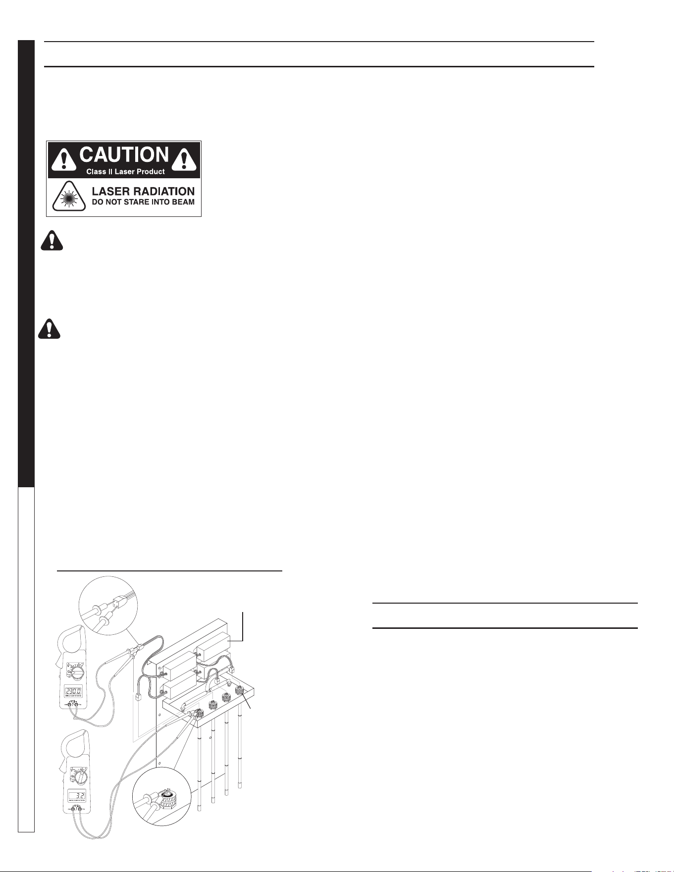
NOTE: There are two fi laments - an upper and a lower -
inside the lamp. Place one of the voltmeter leads on one
of the lamp prongs and, with the other lead, touch all of
the three remaining prongs. If continuity is not achieved
on both upper and lower fi laments, replace the ozone
lamp (Part #6-0534)
To test the power pack, use a voltmeter set on the cor-
rect voltage (120V or 240V). Place one of the voltmeter
leads into the lamp plug where the white wire goes into
it and plug the other voltmeter lead into the lamp plug
where the blue wire goes into it. If no voltage is present
replace the ozone ballast (Part #6-05231 - 120V, Part
#6-05232 - 240V). When ordering an ozone ballast, you
also need the 4-pin connector (Part #6-05233).
Replacing the lamp:
(See Ozone Generator Breakdown)
Lamp replacements are available from your WATER
MAZE Dealer should they need to be replaced. Simply
turn off the power to the CLP at the breaker, remove the
screws on the power pack cover and remove the cover.
Disconnect the plug on the end of the ozone lamp. Now,
loosen the lamp holder locking ring from around the end
of the lamp by turning it counterclockwise and remove
it. Remove the lamp by grabbing the rubber bushing
around the end of the lamp and pulling it straight out.
Remove the rubber bushing from the lamp and install
it on your new lamp, making sure the outer edge of the
bushing is fl ush with the outer edge of the silver end cap
on the lamp. Now, slide the lamp back into the reaction
chamber. The lamp holder may now be reinstalled and
tightened. Reinstall the plug onto the lamp and replace
the power pack cover.
CAUTION: Keep the lamp free of fi ngerprints and
dust particles by only handling the metal end caps
on the lamp. You can clean the lamp with rubbing
alcohol and a soft cloth. A dirty lamp will not allow
maximum ozone output.
SPECIFICATIONS
Energy required 110V:
105VAC MIN., 125VAC MAX., .800 AMP/Ballast
Energy required 220V:
210VAC MIN., 230V MAX., .450AMP/Ballast
Power Consumption: 20 Watts
Average Lamp Life: 9,000 Hours
Lamp Wave length: 185 nm
in hazardous radiation exposure, and may be considered
an act of modifying or new manufacturing of a laser
product under U.S. regulations contained in 21CFR
Chapter 1, subchapter J.
CAUTION: Avoid exposure to direct or strongly
refl ected germicidal ultraviolet rays.
DO NOT STARE INTO BEAM.
ATTENTION: Éviter l'exposition aux rayons ultra-
violets germicides fortement réfl échis.
NE PAS REGARDER DIRECTEMENT LE FAISCEAU.
DANGER: Ultraviolet radiation. Disconnect
Power Before Replacing Lamp.
ATTENTION: Radiation ultraviolette. Débrancher
l'alimentation avant de remplacer la lampe.
DANGER: Connect only to a circuit that is protect-
ed by Ground Fault Circuit Interrupt (GFCI).
DANGER: Raccorder uniquement à un circuit qui
est protégé par un disjoncteur différentiel de fuite
à la terre (DDFT).
Testing the Lamp:
(See Ozone Generator Testing Illus.)
To test the ozone lamp, use a voltmeter set on ohms.
First remove the ozone cover and unplug the lamp plug
from the ozone lamp.
89139700-34
Four Pin
Connector
Ozone
Lamp
Prongs
Ballast
OZONE GENERATOR TESTING
8.913-970.0 - L • WATERMAZE CLP 5024/7034
27
WATER TREATMENT SYSTEM
OPERATOR’S MANUAL
OZONE GENERATOR BREAKDOWN EXPLODED VIEW
89139700-26
OZONE GENERATOR
DISCONNECT F
R
OM ELECTRICAL
SUPP
L
Y BEFORE SE
R
VICING.
DESCONECTE LA CORRIENTE ELECTRICA
ANTES DE
D
AR SER
VICI
O
.
COUPER
L’ALIMEN
TA
TION ÉLECTRI
Q
UE
AV
ANT DE
F
AIRE UNE RÉ
P
AR
A
TION.
DISCONNECT F
R
OM ELECTRICAL
SUPP
L
Y BEFORE SE
R
VICING.
DESCONECTE LA CORRIENTE ELECTRICA
ANTES DE
D
AR SE
R
VICI
O
.
COUPER
L’ALIMEN
TA
TION ÉLECTRI
Q
UE
AV
ANT DE
F
AIRE UNE RÉ
PAR
A
TION.
INDICATOR
L
IGHT OPERATIO
N
A b
r
ight contin
uous light indicates UV
light or ballast de
f
ecti
v
e
.
Una luz luminosa indica que la luz ultra-
violeta o t
r
ans
f
o
r
mador está def
ectuos
o
.
Une lumière claire indique que la lumière
ult
r
aviolette ou le t
rans
f
o
r
mateur est
défectueux.
OPERACION DE LA LUZ
INDICADORA
OPÉRATION DE LE LAMPE
INDIC
A
TEUR
H
OT!
C
ALIENTE!
C
H
A
UD!
C
AUTION
PREC
A
UCION
ATTENTION
8.900-455.0
!
W
ARNING!
A
T
ENC
ION
!
/
A
TT
ENT
I
ON!
!
Ballast
Ozone Lamp
Prongs
On/Off
Switch
Ozone
Lamp
21
9
23
10
1
4
11
19
12
11
17
13
14
6
16
3
22
8
2
20
18
24
7
15
5

8.913-970.0 - L • WATERMAZE CLP 5024/7034
OPERATOR’S MANUAL WATER TREATMENT SYSTEM
28
OZONE GENERATOR BREAKDOWN PARTS LIST
ITEM PART NO. DESCRIPTION QTY
1 8.913-351.0 Ozone Box, Back, 200 1
8.913-357.0 Ozone Box, Back, 400 1
2 8.913-356.0 Ozone Box, Front, 200 1
8.913-360.0 Ozone Box, Front 400 1
3 8.716-095.0 Light, Indicator, Red (200) 2
(400) 4
4 9.802-523.0 Locknut, 3/4" Conduit (200) 2
(400) 4
5 8.716-583.0 Connector, Aluminum Cord
SCH1037 (101) 1
(200) 2
(400) 4
6 8.707-355.0 Ozone Check Valve 1
7 8.716-600.0 Lamp, Ozone Replacement
(200) 2
(400) 4
8 8.900-455.0 Label, Ozone Generator 1
9 9.802-695.0 Nut, 10/32", NF ST ST KEP 4
10 8.706-570.0 Locknut, 3/8" Nylon 2
11 8.706-585.0 Connector, 3/8" x 3/8",
Male Elbow (Poly) 2
12 8.706-594.0 Tee, 3/8" Poly 1
13 8.706-733.0 Bushing, 1/2" Snap 1
14 8.711-733.0 Tubing, 3/8" x 1/2", Vinyl 6 ft.
ITEM PART NO. DESCRIPTION QTY
15 9.802-423.0 Cord, Service, SEO, 16/3 8 ft.
16 8.716-051.0 Switch, Curvette, 120V & 220V 1
17 9.802-515.0 Strain Relief, 1/2" NPT
Ozone Gen 1
18 8.706-544.0 Cushion, 1/2", 8-3/4" x 5-3/4",
200 1
8.706-545.0 Cushion, 1/2", 13-3/4" x 5-3/4",
Rubber, 400 1
19 8.913-352.0 Ozone Box, Top, 200 1
8.913-358.0 Ozone Box, Top, 400 1
20 8.913-353.0 Ozone Box, Bottom, 200 1
8.913-359.0 Ozone Box, Bottom, 400 1
21 8.716-590.0 Ballast, 120/240V, Ozone Gen.
(200) 2
(400) 4
22 9.804-566.0 Screw, 10/32" x 1/2" Slot Pan,
MS ZN 12
23 8.718-968.0 Washer, 10 x SAE ZN 12
24 9.802-798.0 Screw, #10 x 1/2" Tek
Hex Head 8
9.800-022.0 ▲ Label, 120V Ozone Gen 1
8.900-511.0 ▲ Label, 220V Ozone Gen 1
▲ Not Shown

8.913-970.0 - L • WATERMAZE CLP 5024/7034
29
WATER TREATMENT SYSTEM
OPERATOR’S MANUAL
CHEMICAL MAINTENANCE PROGRAM
Combined chlorine has only 1/15th the strength of free
chlorine. Ozonation is used in the CLP system. Chlorine
can be added to help with control if needed.
Inadequate or improper addition of chlorine could result
in algae and bacteria growth. Once algae and bacterial
growth starts, the system must be shock treated. It is
best to minimize the chances of an algae and bacteria
problem.
The killing of bacteria by chlorine exists in two phases:
1. The penetration of the active germicidal principal
(hypochlorous acid) into the bacterial cell.
2. The chemical combination of this ingredient with the
protoplasm (the complex composition which forms
the essential part of plant and animal cells). This
combining is directly responsible for the death of
the organism.
The activity of this germicidal effect is reduced in al-
kaline solutions (those with a pH greater than 7.5) and
expressed as follows:
pH % of Effectiveness
4.0 100.0
5.0 99.6
6.0 95.8
7.0 69.7
8.0 18.7
9.0 2.2
10.0 0.2
Hypochlorite when added to solutions with a pH lower
than 6.0 can produce oxide which is toxic. In vehicle
washing, almost all cleaning compounds are alkaline
in nature. Hypochlorite will still control bacterial growth
and thus smell at higher alkaline ranges, but as the table
indicates, its effectiveness is reduced.
To compensate for this inhibited activity, a larger quantity
of hypochlorite is used. This will control bacterial growth
but will increase operational costs.
Typical hypochlorite has a pH of approximately 11.6. This
high pH will only increase the pH of holding tank water
making pH adjustment more diffi cult.
Trichloro-S-Triazine Trione is a chlorine compound which
has a pH of 3.0 and when added to holding tanks will
aid in the reduction of tank pH levels.
Unlike hypochlorite, which is usually 15 percent chlorine
and will produce sodium or calcium salts in holding tanks,
these new products are 99 percent chlorine which means
Owner Chemical Maintenance Program to
Maintain Recycled Water Quality
Daily monitoring and adjustment of WATER MAZE
recycled water chemistry is essential. If not monitored
and controlled, the recycled water will become chemi-
cally unbalanced resulting in a host of problems such
as algae and bacteria growth, obnoxious odors, iron
discoloration and ultimately it will be unfi t for reuse and
must be disposed of.
The daily monitoring and adjustment maintenance pro-
gram presented herein will, if followed, provide suitable
recyclable wash water. The proper maintenance of the
water is not complicated and depends upon a few basic
principles which are:
1. Physical - effective fi ltration and recirculation of
the water
Effective recirculation of the water through the catch ba-
sin, and the CLP is achieved only if the system is utilized
often (daily 6-8 hours or more) or if the system is set to
recirculate the water throughout the total system. The
CLP has the controls and procedures to achieve continu-
ous effective water recirculation throughout the process.
Therefore, if the CLP is operated properly, it will achieve
the required need of effective fi ltration and recirculation.
2. Chemical - proper adjustment of alkalinity and pH
The most important factor to control and maintain is
the pH of the water (i.e. the acidity or alkalinity). If the
recycled water is acidic (low pH) it will dissolve iron into
solution. The presence of iron of more than 0.2 ppm will
result in rusty staining of virtually any metal the water
comes in contact with. Alkaline water can cause cloudi-
ness and greatly reduces the effectiveness of chlorina-
tion. Many of the cleaning detergents are alkaline and will
make the recycled water too alkaline. Also, high alkaline
water is diffi cult to fi lter and decreases fi lter media life.
The proper pH range to maintain is 6.8 - 7.2.
Alkalinity refers to the soluble salts in the water. These
include bicarbonates, carbonates, hydroxides and other
alkali compounds. The water's total alkalinity controls
its resistance (buffering ability) to large fl uctuations in
pH levels.
Another factor which should be monitored for proper
water chemistry balancing is calcium hardness. The
presence of too much calcium can lead to the formula-
tion of scale in the fi lters.
3. Biological - adequate disinfection, algae, bacteria,
and odor control
Chlorination and ozonation are used to control bacteria,
odor and algae formation. For chlorine to be effective, it
must be available as free chlorine. If the proper pH and
alkalinity is not maintained, or if the water contains dirt
particles, the chlorine will be combined chlorine and not
be effective in the control of algae and bacteria growth.

8.913-970.0 - L • WATERMAZE CLP 5024/7034
OPERATOR’S MANUAL WATER TREATMENT SYSTEM
30
DAILY CHEMICAL MAINTENANCE
that if a solid “puck” of chlorine is used, the total effective-
ness of the puck is superior to that of hypochlorite and
no negative by-products are produced.
Step 1 Collect a water sample from tank #1.
NOTE: Be sure that the water is circulating
from the sump through the CLP system and
back to the catch basin.
Step 2 Using the test strips supplied, measure:
A. The pH.
B. The total chlorine (if using chlorine).
C. The free chlorine (if using chlorine).
D. The alkalinity (if needed).
E. The calcium hardness (if needed).
Step 3 If the pH is 6.8-7.2 go to Step 4, if not, adjust
the pH in the water being recycled between the
oil water separator and the pit to pH 6.8-7.2.
Muriatic acid or liquid alum can be used to
lower the pH. Soda ash (sodium carbonate) or
caustic soda (sodium hydroxide) can be used
to raise the pH.
Adjust the pH gradually allowing complete mix-
ing after adding chemical. Take a new sample,
read the pH and continue to adjust gradually
until the desired pH is achieved.
Step 4 The total alkalinity should be between 50-150
ppm. If the total alkalinity is too low add sodium
bicarbonate to raise it. If total alkalinity is too
high, add muriatic acid to bring it within accept-
able range. This will also decrease the pH. If
the pH goes below 7.0, add sodium bicarbon-
ate to increase the pH. This procedure may
have to be repeated several times to get the
pH and a total alkalinity into the proper range.
Step 5 The calcium hardness should not exceed 25
grains. If it is too high, some water must be
removed from the system and fresh makeup
water added. Alternatively, an ion exchange
water softener or an ionizer may have to be
added to the system to reduce and maintain
lower calcium hardness levels.
Step 6 Free chlorine levels should be 1-2 ppm if chlo-
rine is added for additional control. A 10-50%
concentrated liquid chlorine is available at
pool supply outlets. Household bleach can be
used, but contains only 5% chlorine. Chlorine
continually dissipates and becomes used up
and the chlorine level must be adjusted daily.
Remember chlorine is most effective when the
pH level is correct (6.8-7.2).
Initially, in order to achieve proper water chemistry bal-
ance, extra time is needed. However, once achieved, it
can be easily maintained in a minimum amount of time
by daily monitoring and adjustment.
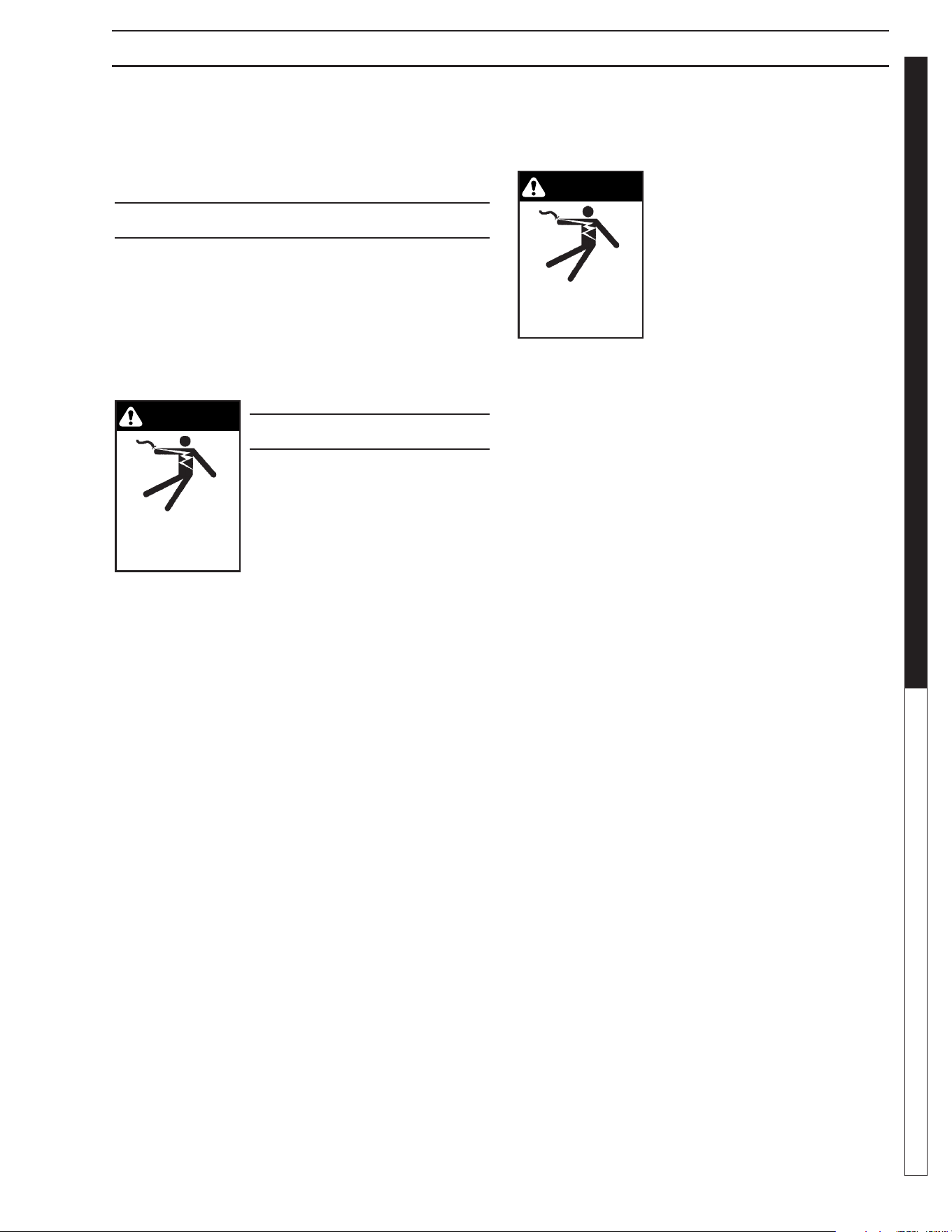
8.913-970.0 - L • WATERMAZE CLP 5024/7034
31
WATER TREATMENT SYSTEM
OPERATOR’S MANUAL
PUMP OPERATION AND MAINTENANCE
The CLP machine has an ORP/pH Controller which
automatically maintains the ORP and pH levels. Total
alkalinity and hardness must be checked manually.
CENTRIFUGAL PUMP
Your centrifugal pump has been quality-built and engi-
neered to give you effi cient, dependable service. It is
equipped with union connectors to make installation and
future service easier.
The advanced design uses a single speed motor which
reduces operation and maintenance to simple, common-
sense procedures.
PUMP OPERATION
(Ozone, Filter, or Transfer)
WARNING: Do not touch pumps,
pump motors, water or discharge
piping when the pumps are con-
nected to electrical power. Do not
handle a pump or pump motor
with wet hands or when standing
on a wet or damp surface or in
water. Never touch a pump or discharge piping when
a machine is operating or fails to operate. Always
disconnect the pump cord (power) before handling.
1. The shaft seal depends on water for lubrication.
Do not operate the pump unless there is water. Dry
running (pump not pumping water) will cause seal
damage and eventual pump failure.
2. The motor is equipped with an automatic reset
thermal protector. This means if the temperature in
the motor should rise unduly, the switch will cut off
all power before damage can be done to the motor.
When the motor has cooled suffi ciently, the switch
will reset automatically and restart the motor. If the
protector trips repeatedly (cycling on protector) the
pump should be removed and checked for the cause
of the diffi culty. Low voltage, long extension cords,
clogged impeller, very low head
or lift, etc., could cause cycling.
Cycling of the protector will cause
eventual motor burnout.
PUMP
MAINTENANCE
(Sump)
WARNING: Before attempting to service, discon-
nect power from machine. Do not handle the pump
with wet hands or when standing on a wet or damp
surface or in water. Failure to follow precautions can
result in personal injury and /or property damage.
NOTE: Only qualifi ed electricians or servicemen should
attempt to repair this machine. Improper repair and/or
assembly can cause an electrical shock hazard.
1. Bearings in this machine are pre-lubricated. No ad-
ditional lubrication is necessary.
2. Cleaning - Occasionally clean the sump pit and pump
if dirt or foreign matter accumulate. Small stones,
gravel, sand, dirt, silt, etc. can clog and damage
the pump and pump seal, eventually causing pump
failure.
3. Disassembly of the motor prior to expiration of the
warranty will void the warranty. It may also cause
internal leakage and damage to the machine. If re-
pairs are required, return the pump to a local service
station.
4. If the motor has been disassembled or the switch
chamber opened after the warranty expiration date,
the O-rings and gaskets must be replaced. Care
must be taken to assure that the seals, the switch
cover and air tube gaskets do not leak.
5. The pump should be checked for proper operation
weekly or monthly by watching the operation of the
pump. If anything has changed since the pump was
new, the pump should be examined, and repaired if
necessary.
WARNING
RISK OF ELECTRIC
SHOCK: USE CAUTION
WHEN HANDLING.
WARNING
RISK OF ELECTRIC
SHOCK: USE CAUTION
WHEN HANDLING.
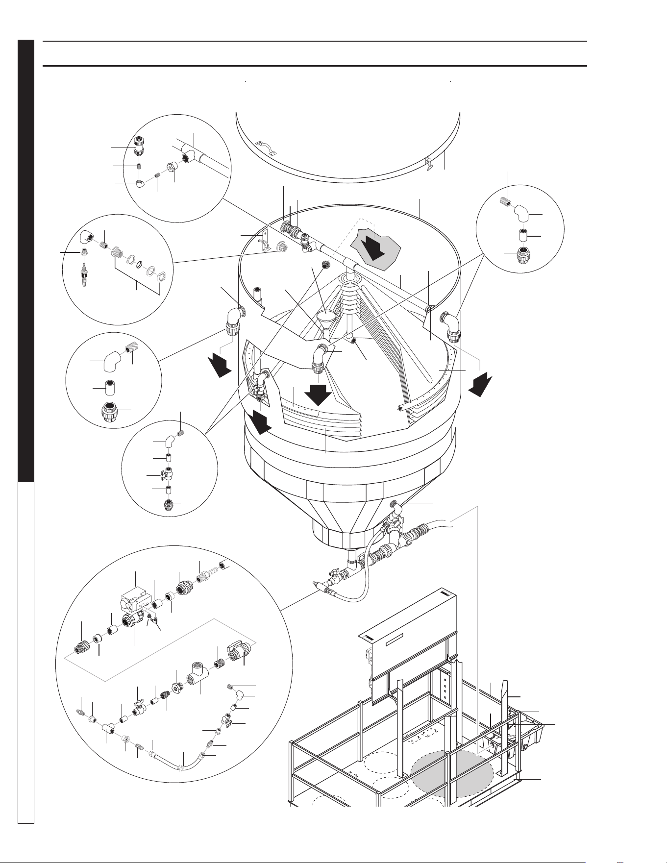
8.913-970.0 - L • WATERMAZE CLP 5024/7034
OPERATOR’S MANUAL WATER TREATMENT SYSTEM
32
CLP-5024 MAIN TANK PLUMBING EXPLODED VIEW
17
W
A
RNI
NG
P
R
E
C
A
U
T
I
O
N
/
A
T
T
E
N
T
I
O
N
D
O
N
O
T
S
T
A
N
D
O
R
S
T
E
P
O
N
T
H
I
S
P
L
A
T
F
O
R
M
W
A
R
N
I
N
G
P
R
E
C
A
U
T
I
O
N
/
A
T
T
E
N
T
I
O
N
D
O
N
O
T
S
T
A
N
D
O
R
S
T
E
P
O
N
T
H
I
S
P
L
A
T
F
O
R
M
89139700-6
4
5
3
2
1
Main Tank
60
1
22
14
21
23
34
14
13
42
63
61
44
14
45
58
59
11
35
12
4
31
36
18, 19, 20
46
15
40
41
62
62
33
48
53
54
55
49
29
43
23
16
2
30
3
6
3
15
23
9
50
56
25
27
24
26
30
38
52
22
37
39
28
29
23
30
23
5
10
31
12
14
Orp Injector
Assy.
57
32
7
8
47
9
10
41
31
32
51
Tank Lid

8.913-970.0 - L • WATERMAZE CLP 5024/7034
33
WATER TREATMENT SYSTEM
OPERATOR’S MANUAL
CLP-5024 MAIN TANK PLUMBING EXPLODED VIEW PARTS LIST
ITEM PART NO. DESCRIPTION QTY
1 8.719-182.0 Lid, 300 Gal. Clarifi er Tank 1
2 8.719-180.0 Tank, 300 Gal Clarifi er, w/o Lid 1
3 8.706-490.0 Bulkhead, 1-1/2" Polypro 3
4 8.750-743.0 Bulkhead, 1/2" PVC 1
5 8.719-181.0 Cone, CLP 5000 Sup Colescn,
w/Hole/Slot/Lip 1
6 8.719-183.0 Cone, CLP 5000 Coalescing,
w/Hole, w/Slot 4
7 8.719-184.0 Cone, CLP 500 Coalescing,
w/Hole, No Slot 1
8 8.711-816.0 Hose, 2", Gray Conduit, / ft. 8.75 ft
9 8.706-469.0 Union,1-1/2" SLIP x SLIP,
PVC 80, Spea 2
10 8.706-441.0 Adapter, 1.5" SLIP x MT,
PVC 80 2
11 8.706-367.0 Pipe, 1.5", PVC 80, /ft 8 ft
12 8.706-426.0 Tee, 1.5" S x S x S, PVC 80 3
13 8.707-298.0 Valve, Ball Check 1/2" PVC 1
14 8.706-467.0 Nipple, 1/2", PVC 80, Close 4
15 8.706-370.0 Elbow, 1/2" FIPT x FIPT,
PVC 80, 90° 2
16 8.706-406.0 Bushing 1-1/2" x 1/2" SPGXF,
PVC 80 Spearo 1
17 8.706-407.0 Bushing, 1/2" x 1/4" MT x FT,
PVC 80 1
18 8.706-375.0 Elbow, 1-1/2" FT x FT,
PVC 80, 90° 1
19 8.706-492.0 Nipple, 1-1/2" x 2-1/2", PVC 80 1
20 8.706-468.0 Nipple 1.5" x 3" PVC 80 1
21 8.706-683.0 Funnel, Plastic Oil Skimmer 1
22 8.706-378.0 Elbow, 1" SLIP x FIPT,
PVC 80, 90° 3
23 8.706-482.0 Nipple, 1-1/2" x 6", PVC 80 1 ft
24 8.707-359.0 Valve, 1" S 80 PVC S x S,
Mold in Place Ba 2
25 8.706-597.0 Union,
1", S x S, PVC 80 Spears
2
26 8.913-085.0 Bracket, Orp/pH Sensors, Clar. 1
27 8.706-484.0 Bulkhead, 1", Polypro 1
28 8.706-439.0 Nipple, 1", PVC 80, Close 1
29 8.707-359.0 Valve,1 "S 80 PVC S x S
Mold in Place Ba 2
30 8.706-447.0 Adapter, 1", 3/4" S x FIPT,
PVC 80 3
31 8.706-899.0 Nipple, 3/4" JIC x 3/4" Pipe 3
32 9.802-152.0 Swivel, 3/4" SAE Fem,
Push-on 2
33 9.802-261.0 Hose 3/4" 5.25 ft
34 8.706-430.0 Tee, 1" S x S, PVC 80 1
ITEM PART NO. DESCRIPTION QTY
35 8.706-409.0 Adapter, 1" MT x SLIP,
PVC 80 1
36 8.706-418.0 Bush Redcr, 2 x 1 PVC-80
MPTXFPT Spears Onl 1
37 8.706-436.0 Tee, 2" FT x FT x FT, PVC 80 1
38 8.706-466.0 Nipple, 2" Close, PVC 80 1
39 8.707-349.0 Valve, 2" Single Union Ball 1
40 8.706-451.0 Adapter, 2" SLIP x MT, PVC 80 1
41 8.706-367.0 Pipe, 1.5" Gray, PVC 80 1 ft
42 8.756-648.0 VALVE, BALL, 1-1/2", PNEU ACT,
NO SOL 1
43 8.756-462.0 SOLENOID, VALVE, 24VAC,
SV61 1
8.706-777.0 ▲ Nipple, 1/4" Close 1
44 8.706-958.0 Hose Barb, 1/4" Barb x 1/4"
Pipe, 90° 1
45 8.706-473.0 Union, 2" SLIP x SLIP,
PVC 80 Spear 1
46 8.706-321.0 Box, Junction 3 Hole, 1/2" 1
47 8.716-324.0 Box, Junction 4 Hole, 1/2" 1
48 8.913-327.0 Rail, Guard, End, Delta-1000 2
49 8.913-326.0 Rail, Guard, Side Delta-1000 2
50 8.913-138.0 Stand, Tank, CLP 5000,
Low Profi le 1
51 8.913-139.0 Base, Platform Assy 1
52 8.706-479.0 Bulkhead, 2" NPT, Polypro 1
53 8.706-466.0 Nipple, 2" Close, PVC 80 1
54 8.706-384.0 Elbow, 2" SLIP x FPT PVC 80 1
55 8.706-473.0 Union, 2" SLIP x SLIP PVC 80
Spear 1
56 8.706-583.0 Pipe, 2", Gray, PVC 80 /ft .25 ft
57 8.706-372.0 Elbow, 1-1/2" ST x FT,
PVC 80, 90° 1
58 8.706-492.0 Nipple, 1-1/2" x 2-1/2"
PVC 80 1
59 8.706-367.0 Pipe, 1.5", PVC 80 /ft .25 ft
60 8.706-375.0 Elbow, 1-1/2" FT x FT,
PVC 80, 90° 1
61 8.706-453.0 Adapter, 2" MT x 2" M
Hose Insert, Plas 1
62 8.706-413.0 BUSHING, 2' X 1 1/2' SLIP,
PVC 80 2
63 8.756-650.0 MUFFLER, EXHAUST,
1/4" NPT, BRASS 2
▲ Not Shown
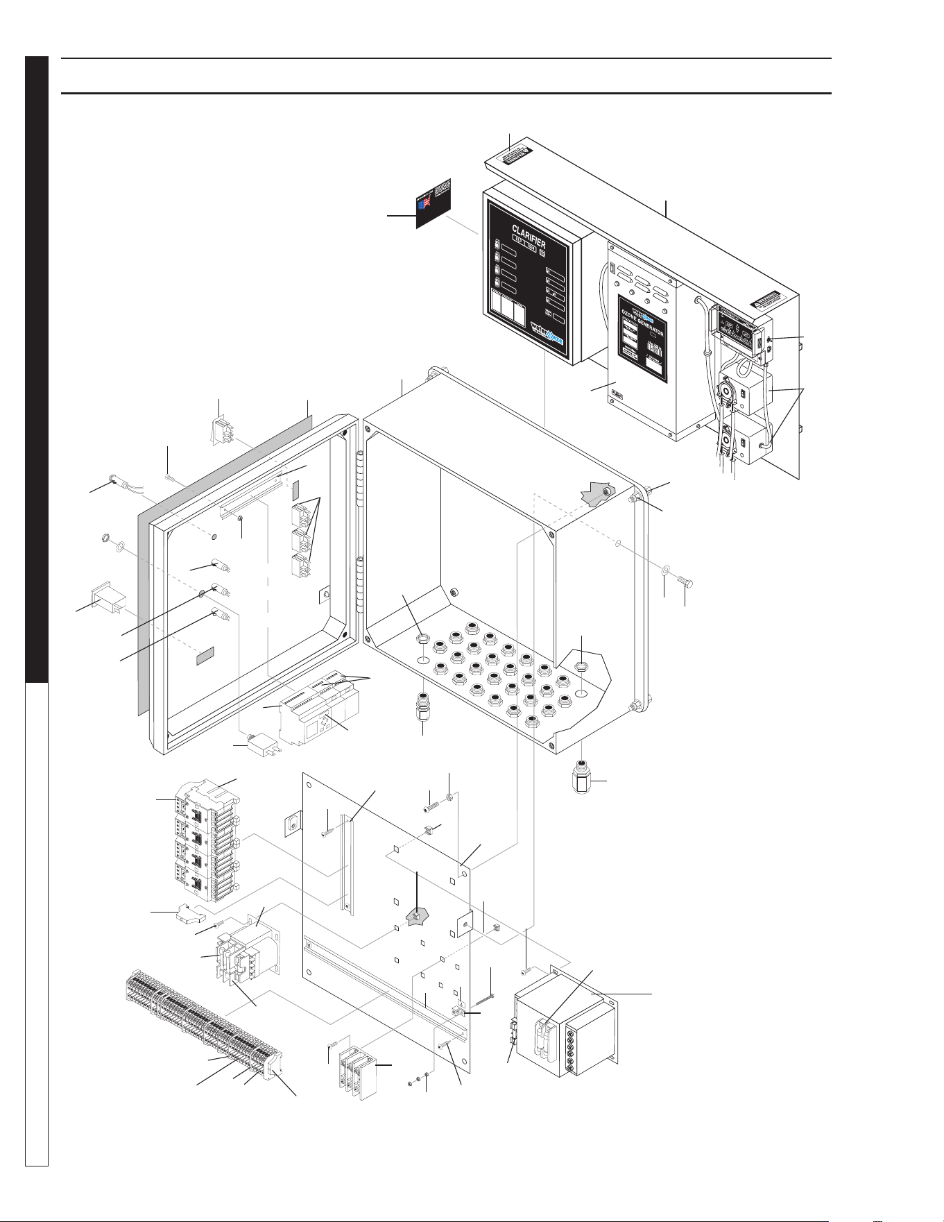
8.913-970.0 - L • WATERMAZE CLP 5024/7034
OPERATOR’S MANUAL WATER TREATMENT SYSTEM
34
ELECTRICAL BOX EXPLODED VIEW
89139700-35
GROUND
40
28
33
30
30
35
41
42
28
1
4
Green
16
4
4
5
1
32
19
18
7
6
9
8
2
31
17
20
27
28
24
14
15
13
45
49
48
47
46
34
43
3
24
29
31
12
11
10
22
23
21
25
26
37
39
50
55
38
36
51
53
52
Green
Green
Blue
54

8.913-970.0 - L • WATERMAZE CLP 5024/7034
35
WATER TREATMENT SYSTEM
OPERATOR’S MANUAL
ELECTRICAL BOX EXPLODED VIEW
ITEM PART NO. DESCRIPTION QTY
1 8.716-051.0 Switch, Curvette 2P,
120/230V 4
2 8.716-091.0 Switch, Momentary Push,
100S Use w/2- 3020 1
3 9.802-457.0 Din Rail, 35mm 14"
4 9.803-652.0 Light, Indicator,
Green 28 Volt 3
5 9.803-650.0 Light, Indicator, Blue 28V 1
6 8.756-361.0 Relay, Smart, 24V, 8I/4O, FS 1
7 8.755-623.0 Logo Expansion Module 4I/4O 2
8 8.724-267.0 Contactor, DP, C25DNY151,
24 VAC 4
9 8.724-301.0 Overload, XTOB004CC1DP,
2.4 - 4.0 Sump & Ozone
(7034B Models) 2
8.724-303.0 Overload, XTOB010CC1DP,
6.0 - 10.0 Filter & Transfer
(7034B Models) 2
8.724-300.0 Overload, XTOB2p4CC1DP,
1.6 - 2.4 Sump & Ozone
(7034C Models) 2
8.724-301.0 Overload, XTOB004CC1DP,
2.4 - 4.0 Filter & Transfer
(7034C Models) 2
8.724-301.0 Overload, XTOB004CC1DP,
2.4 - 4.0 Sump & Ozone
(5024B Models) 2
8.724-302.0 Overload, XTOB006CC1DP,
4.0 - 6.0 Filter & Transfer
(5024B Models) 2
8.724-300.0 Overload, XTOB2P4CC1DP,
1.6 - 2.4 Sump & Ozone
(5024C Models) 2
8.724-301.0 Overload, XTOB004CC1DP,
2.4 - 4.0 Filter & Transfer
(5024C Models) 2
10 8.716-873.0 Transformer, Multi-tap, .500KVA,
50/60 Hz 1
11 8.716-180.0 Fuse, KTK-R4 600V
Midget Fuse
(4 Amp) 2
12 8.716-194.0 Fuse, Paper, 7 Amp, 250V,
FNM7 1
13 8.716-904.0 Transformer, 120/240V-24V,
.100KVA 1
14 9.802-465.0 Fuse, Fnq-R3 600V
Midget TD 2
15 9.803-664.0 Fuse, Paper, Buss Fnm5,
250V Midget TD 1
16 9.802-283.0 Hour Meter, 1
17 9.802-457.0 Din Rail, 35mm 10"
18 8.716-280.0 Box, Plastic, 18 x 16 x 9.25
w/Hinged Lid 1
ITEM PART NO. DESCRIPTION QTY
19 8.940-487.0 Label, CLP-7034,
Electrical Box
(7034 Models) 1
8.916-747.0 Label, CLP-5024,
Elec Box
(5024 Models) 1
20 9.802-514.0 Strain Relief, Lt, STR,
1/2 NPT, .23-.45d 27
21 9.802-525.0 Locknut, 1/2" 8463 27
22 9.802-515.0 Strain Relief,
STRT,
Lq Tite 3200
1
23 9.802-525.0 Locknut, 1/2" 8463 1
24 9.802-759.0 Screw,
10/32" x 1/2" BHSOC
Blk
6
25 8.718-618.0 Bolt,
5/16" x 3/4" NC Gr 5
Cs Zn
4
26 9.802-778.0 Nut, Whiz Loc, 5/16 Flange 4
27 9.802-759.0 Screw, 10/32" x 1/2" BHSOC
Blk 4
28 9.802-695.0 Nut, 10/32" Keps 5
29 8.716-117.0 Block, Power Distr 150
DGRC 1
30 9.802-791.0 Nut, Cage, 10/32" x 16 Ga 8
31 8.718-936.0 Screw, #8 x 1/2", Phillips,
Zinc Plate 4
32 9.802-457.0 Din Rail, 35mm 6
33 9.802-771.0 Screw,
10/32" x 3/4" BH
SOC CS
2
34 9.802-793.0 Nut, Cage, 1/4" x 16 Ga 4
35 9.802-765.0 Screw 1/4" x 1/2" 4
36 8.900-522.0 Label, CLP Warning,
Do Not Stand Or Step 1
37 8.905-716.0 Ozone Generator,
Series 400 (120V) 1
8.905-714.0 Ozone Generator,
Series 200 (120V) 1
38 8.715-377.0 Contrlr, 250 Digital
Orp/pH w/MTRing Pmps 1
8.716-990.0 Controller Only,
Orp/pH Digital Ch250 1
8.716-905.0 ▲ Sensor, pH 1
8.716-906.0 ▲ Sensor, Orp 1
39 8.715-378.0 Pump, VSP20
Metering, 24V 2
40 8.716-460.0 Terminal,
Grounding Lug,
Lama 6-14-Q 1
41 9.803-660.0 Screw, 8-32 x 1-1/4",
MPH PHD PL 1
42 9.800-040.0 Label, Ground Symbol 1
43 8.918-076.0 Wlmt, Electrical Stand-off, CLP 1
44 8.730-244.0 ▲ Label, Scale Solver 1

8.913-970.0 - L • WATERMAZE CLP 5024/7034
OPERATOR’S MANUAL WATER TREATMENT SYSTEM
36
ELECTRICAL BOX EXPLODED VIEW
ITEM PART NO. DESCRIPTION QTY
45 9.804-595.0 End Bracket,
Entrelec, 103-002-26 2
46 8.716-396.0 Terminal Block,
Entrelec,
115-116-07M4/6 43
47 8.716-399.0 End Cover, Entrelec, 11836816
P-ON 3
48 8.716-398.0 Terminal Block, Blue,
Entrelec, 125116-01 7
49 8.716-399.0 End Cover, Entrelec,
11836816 P-on 10
50 8.940-055.0 Label, Assembled in USA 1
51 9.807-876.0 ▲ PLC Logic, CLP 1 PH, FS 1
9.807-877.0 ▲ PLC Logic, CLP 3 PH, FS 1
52 8.718-603.0 Bolt, 1/4" x 3/4" SS 2
53 8.718-568.0 Washer, 1/4" SS
Sealing Rubber 2
54 9.804-595.0 End Bracket 2
55 8.913-107.0 Mount/Cover, E-Box 1
56 8.921-217.0 ▲ I BAR, PLC with
two expansions 2
57 8.712-861.0 ▲ Edge Trim 0.66'
58 8.921-222.0 ▲ Q BAR, Dual expansion Top 1
59 8.921-221.0 ▲ Q BAR, PLC with two
expansions 1
▲ Not Shown
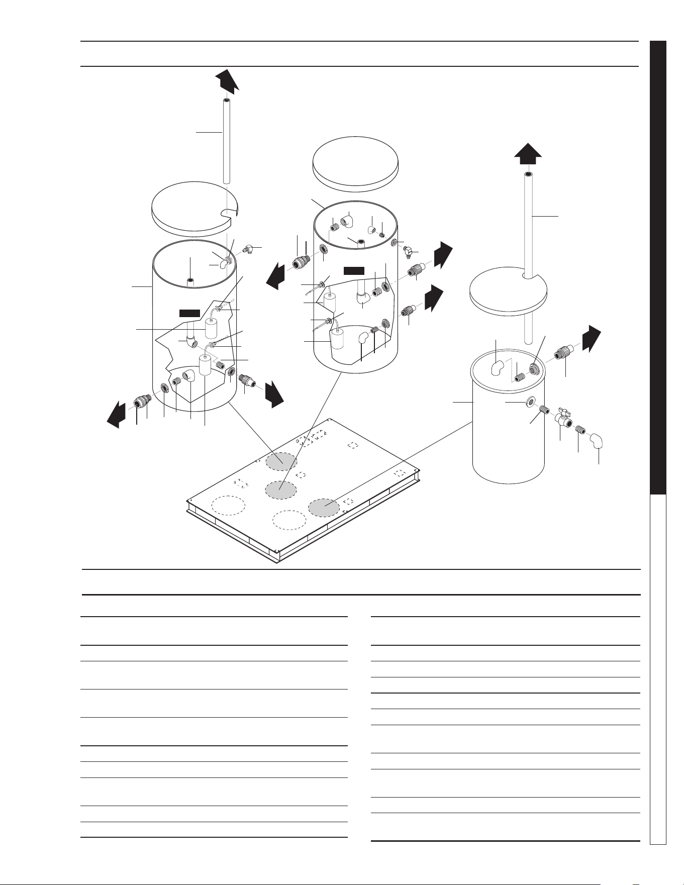
8.913-970.0 - L • WATERMAZE CLP 5024/7034
37
WATER TREATMENT SYSTEM
OPERATOR’S MANUAL
CLP-5024 STORAGE TANKS PLUMBING EXPLODED VIEW
CLP-5024 STORAGE TANKS PLUMBING PARTS LIST
TANK 2
TANK 1
89139700-4
11
10
9
8
6
7
4
2
1
6
2
4
2
4
Tank 1
Tank 2
12
17
17
14 (2.5')
8
Oil
Collection
Barrel
9
8
9
16
9
7
13
7
19
10
10
10
20
18
5
(FS3)
6
3
(FS4)
7
6
19
20
18
7
6
7
6
3
(FS6)
5 (FS5)
2
4
2
4
10
9
7
10
11
10
6
10
21
9
10
6
9
15 (6')
1
ITEM PART NO. DESCRIPTION QTY
1 8.719-170.0 Tank, 65 Gal Blck Vert Poly,
w/Lid, TCTT2240AA 2
2 8.750-743.0 Bulkhead, 1/2" Polypro 4
3 8.716-142.0 Switch, Float, N/O, .20
PMDWOP, 1003825 (Black) 2
4 9.802-514.0 Strain Relief, Lt, Str, 1/2 NPT,
.23-.45D 4
5 8.716-143.0 Switch, Float, N/C #1003826
(Gray) 2
6 8.706-490.0 Bulkhead, 1-1/2" Poly 7
7 8.706-441.0 Adapter, 1.5" Slip x MT, PVC 80 5
8 8.706-470.0 Union, 1-1/2" Slip x Thread,
PVC 80 Spears 2
9 8.706-372.0 Elbow, 1-1/2" S x T, PVC 80, 90° 6
10 8.706-424.0 Nipple, 1.5" X Close, PVC 80 8
ITEM PART NO. DESCRIPTION QTY
11 8.707-362.0 Valve, 1-1/2" T x T Molded S
80 PVC BA 1
12 8.706-367.0 Pipe, 1.5", PVC 80, /ft 4 ft
13 8.706-3670 Pipe, 1.5", PVC 80, /ft 4 ft
14 8.706-583.0 Pipe, 2", Gray, PVC 80 /ft 2.5 ft
15 8.706-367.0 Pipe, 1.5", PVC 80, /ft 6 ft
16 8.706-374.0
Elbow, 1- 1/2" S X S, PVC 80,
90°
1
17 8.706-377.0 Elbow, 3/4" FIPT X FIPT,
PVC 80, 90° 2
18 9.802-052.0 Bulkhead, 3/4" Polypro 2
19 9.803-557.0 Elbow, 3/4" SAE x 3/4", 90°,
Brass 2
20 8.706-369.0 Nipple, 3/4", PVC 80, Close 2
21 8.719-169.0 Tank, 26 Gallon Black Vert Poly
w/Lid 1
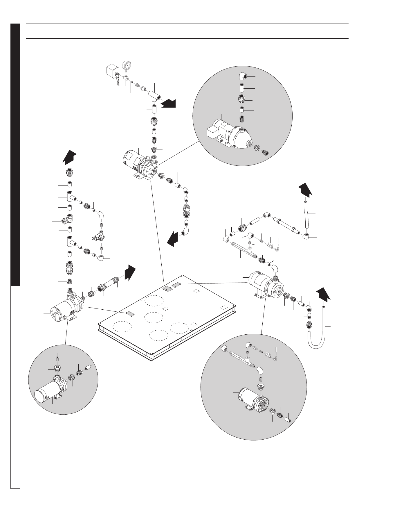
8.913-970.0 - L • WATERMAZE CLP 5024/7034
OPERATOR’S MANUAL WATER TREATMENT SYSTEM
38
CLP-5024 PUMPS PLUMBING EXPLODED VIEW
89139700-7
13
1
3
6
12
10
Filter Pump
(3 Phase)
25
31
30
23
24
20
19
21
28
41
11
9
6
10
6
33
8
4
27
3
1
7
22
29
26
13
12
16
18
25
16
2
2
3
3
3
3
5
6
15
6
4
4
42
Valve 20
26
16
6
6
6
14
35
38
37
36
34
3
5
6
6
6
32
34
6
41
39
6
24
39
41
41
6
28
28
27
28
28
14
6
16
17
15
14
Transfer Pump
(3 Phase)
Transfer Pump
(1 Phase Parts Only)
Ozone Pump
(3 Phase)
Ozone Pump
(1 Phase Parts Only)
Filter Pump
(1 Phase Parts Only)
3
6
43
43
45
45
44
44

8.913-970.0 - L • WATERMAZE CLP 5024/7034
39
WATER TREATMENT SYSTEM
OPERATOR’S MANUAL
CLP-5024 PUMPS PLUMBING EXPLODED VIEW PARTS LIST
ITEM PART NO. DESCRIPTION QTY
1 8.706-373.0 Elbow, 1" S x S, PVC 80, 90° 1
2 8.706-405.0 Bushing, 1-1/4" x 1" MT x FT,
PVC 80 2
3 8.706-409.0 Adapter, 1" MT x SLIP, PVC 80 5
4 8.706-371.0 Elbow, 1" S x S, PVC 80, 45° 3
5 8.706-469.0 Union,1-1/2" SLIP x SLIP,
PVC 80, Spea 2
6 8.706-366.0 Pipe, 1", PVC 80, /ft 1 ft
7 8.706-430.0 Tee, 1" S x S, PVC 80 1
8 8.706-447.0 Adapter, 1", 3/4" S x FIPT,
PVC 80 1
9 8.706-923.0 Bushing, 3/4" x 1/4" Pipe 1
10 8.706-777.0 Nipple, 1/4" Close 10
11 8.706-858.0 Tee, 1/4" Street” 1
12 8.712-154.0 Gauge, Pressure 0-100 1/4" 1
13 8.716-154.0 Swtch, Pres SQ D, N/C 1
14 8.706-378.0 Elbow, 1" SLIP x FIPT, PVC 80,
90° 3
15 8.706-780.0 Nipple, 1/4" Hex 2
16 8.706-597.0 Union,
1", S x S, PVC 80, Spears
4
17 8.716-697.0 Solenoid,
Water Maze, PVC 24V
1
18 8.707-344.0 Valve, PVC 1.5" SLIP x SLIP,
Gate 1
19 8.707-297.0 Valve, 1.5" PVC Ball Check 1
20 8.706-461.0 Nipple, 1-1/4" Close, PVC 80 1
21 8.706-415.0 Bushing, 1.5" MT x 1.25" Ft,
PVC 80 1
22 8.706-424.0 Nipple, 1.5" x Close, PVC 80 1
23 8.706-375.0 Elbow, 1-1/2" FT x FT, PVC 80,
90° 1
24 8.706-441.0 Adapter, 1.5" SLIP x MT,
PVC 80 3
25 8.711-812.0 Hose, 1", Gray Conduit" 10 ft
26 8.706-373.0 Elbow, 1" S x S, PVC 80, 90° 2
27 8.706-431.0 Tee, 1-1/2" x 1-1/2" x 1" SLIP,
PVC 2
28 8.706-367.0 Pipe, 1.5", PVC 80, /ft 1 ft
29 8.706-378.0 Elbow, 1" SLIP x FIPT,
PVC 80, 90° 1
30 8.706-471.0 Union,1" SLIP x Fmle Thred,
PVC 80 Spea 1
31 8.709-431.0 Injector, Ozone w/o Chk Valve 1
32 8.707-321.0 Valve, Ozone Meter, 1/4"
5310.002 Plas 1
33 8.706-587.0 Nipple, 1/2" x1/4", Hex Red.
(Poly) 1
34 8.706-405.0 Bushing, 1-1/4" x 1" MT x FT,
PVC 80 2
35 8.706-467.0 Nipple, 1/2", PVC 80, Close 2
ITEM PART NO. DESCRIPTION QTY
36 8.706-588.0 Connector, 3/8" x 1/4",
Male Elbow, Pol 1
37 8.711-733.0 Tubing, 3/8" x 1/2" Vinyl,
per Foot 10 ft
38 8.706-370.0 Elbow, 1/2" FIPT x FIPT,
PVC 80, 90° 1
39 8.706-439.0 Nipple, 1", PVC 80, Close 2
40 8.706-366.0 Pipe", PVC 80, /Ft 0.25
41 8.706-404.0 Bushing, 1-1/2" x 1" MT x FT,
PVC 80 4
42 8.707-300.0 Valve, 1" PVC Ball Check 1
43 8.715-382.0 Pump, Transfer, 1/2 HP, 1 PH
(CLP-5024A) 1
8.756-758.0 Pump,
SCOT 208/230-460V 3PH,
20GPM/50PSI
(CLP-5024B, C) 1
44 8.917-760.0 Pump, Filter, 3/4 HP, 1 PH
(CLP-5024A) 1
8.756-758.0 Pump, SCOT 208/230-460V
3PH, 20GPM/50PSI
(CLP-5024B, C) 1
45 8.917-760.0 Pump, Ozone, 3/4 HP, 1 PH
(CLP-5024A) 1
8.723-219.0 Pump, Ozone, 3/4 HP, 3 PH
(CLP-5024B, C) 1
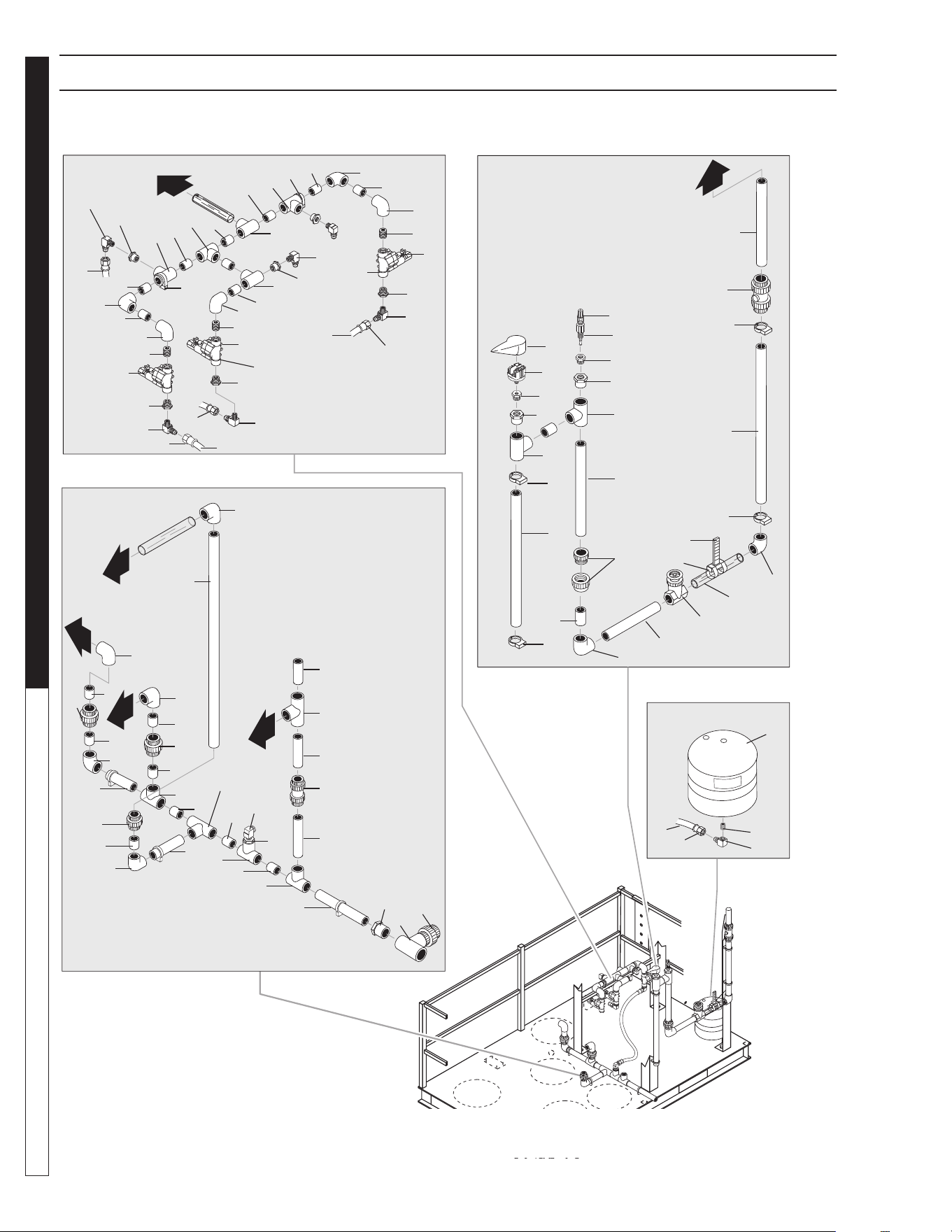
8.913-970.0 - L • WATERMAZE CLP 5024/7034
OPERATOR’S MANUAL WATER TREATMENT SYSTEM
40
CLP-5024 PLUMBING EXPLODED VIEW
89139700-8
5
11
14
9
7
12
Flow Meter
Surge Tank
Manifold
Drain line
5
8
11
13
4
7
13
7
13
7
13
12
13
6
3
10
Valve 9
2
1
9
Valve 17
5
4
7
7
13
11
12
3
13
6
8
13
11
3
10
10
2
1
8
22
1
2
8
33
21
33
33
33
33
21
21
21
21
21
21
21
21
21
21
21
21
21
21
35
34
17
17
29
28
27
26
32
32
32
21
14
Ph Injector
15
16
17
21
32
21
21
21
17
16
15
19
18
20
20
21
24
25
23
30
31
23
20
20
26
38
37
36
40
39
17
17
17

8.913-970.0 - L • WATERMAZE CLP 5024/7034
41
WATER TREATMENT SYSTEM
OPERATOR’S MANUAL
CLP-5024 PLUMBING EXPLODED VIEW PARTS LIST
ITEM PART NO. DESCRIPTION QTY
1 9.802-132.0 Elbow, 3/4" JIC X 1/2", 90° 3
2 8.706-928.0 Bushing, 1" x 1/2" Black Poly
Reducer 3
3 8.706-439.0 Nipple, 1", PVC 80, Close 3
4 8.706-447.0 Adapter, 1", 3/4" S x FIPT,
PVC 80 3
5 9.803-557.0 Elbow, 3/4" SAE X 3/4", 90°,
Brass 3
6 8.706-373.0 Elbow, 1" S x S, PVC 80, 90° 2
7 8.706-430.0 Tee, 1" S x S, PVC 80 5
8 9.802-152.0 Swivel, 3/4" SAE Fem,
Push-on 8
9 9.802-261.0 Hose 3/4" 15 ft
10 8.716-697.0 Solenoid, Water Maze,
PVC 24V 3
11 8.706-378.0 Elbow, 1" SLIP X FIPT,
PVC 80, 90° 3
12 8.706-422.0 Hanger, Pipe, 1-1/4" Click #40 2
13 8.706-482.0 Nipple, 1-1/2" x 6", PVC 80 8
14 8.716-986.0 Injector, I.P.F. Orp/Vsp 20
Metering 1
15 8.706-407.0 Bushing, 1/2" X 1/4" MT x Ft,
PVC 80" 2
16 8.706-406.0 Bushing, 1-1/2"x1/2" SPGXFT,
PVC 80 Spearo 16
17 8.706-426.0 Tee, 1.5" S x S x S, PVC 80 7
18 8.716-156.0 Switch, Pressure,
PM11120A-1PF, 1-PSI 1
19 8.716-157.0 Protector, Pressure Switch,
3302-001 1
20 8.706-422.0 Hanger, Pipe, 1-1/4" Click #40 4
21 8.706-367.0 Pipe, 1.5', PVC 80 /Ft. 21.75'
22 9.802-261.0 Hose 3/4" 34"
23 8.706-374.0 Elbow, 1-1/2" S x S, PVC 80,
90° 2
24 8.707-344.0 Valve, PVC 1.5" SLIP x SLIP,
Gate 1
25 8.706-360.0 Pipe, 1.5" PVC Clear, /Ft 1 ft
26 8.707-299.0 Valve, 1.5" Swing Chk, PVC
Comp P#0107 2
27 8.706-476.0 Union, 2" FS x FT, PVC 80
Spears 1
28 8.706-434.0 Tee, 2" SLIP x SLIP x SLIP,
PVC 80 1
29 8.706-413.0 Bushing, 2" X 1-1/2" SLIP,
PVC 80 1
30 8.712-136.0 Gauge, Flowmeter 1.5 1
31 8.709-083.0 Clamp, 3-1/2" SS Band 2
ITEM PART NO. DESCRIPTION QTY
32 8.706-469.0 Union,1-1/2" Slip x Slip, PVC 80
Spea 4
33 8.706-374.0 Elbow,
1-1/2" S x S, PVC 80,
90
° 4
34 8.706-406.0 Bushing1-1/2" x 1/2"SPG x FT,
PVC 80 Spearo 1
35 9.802-132.0 Elbow, 3/4" JIC x 1/2", 90° 1
36 8.719-176.0 Tank, 4.4 Gal Prepressurizd,
Blue, Wtrstx-102 1
37 8.706-799.0 Nipple, 3/4" Close 1
38 8.706-823.0 Elbow, 3/4" Female, 90° 1
39 8.706-899.0 Nipple, 3/4" JIC x 3/4" Pipe 1
40 9.802-261.0 Hose 3/4" 43"
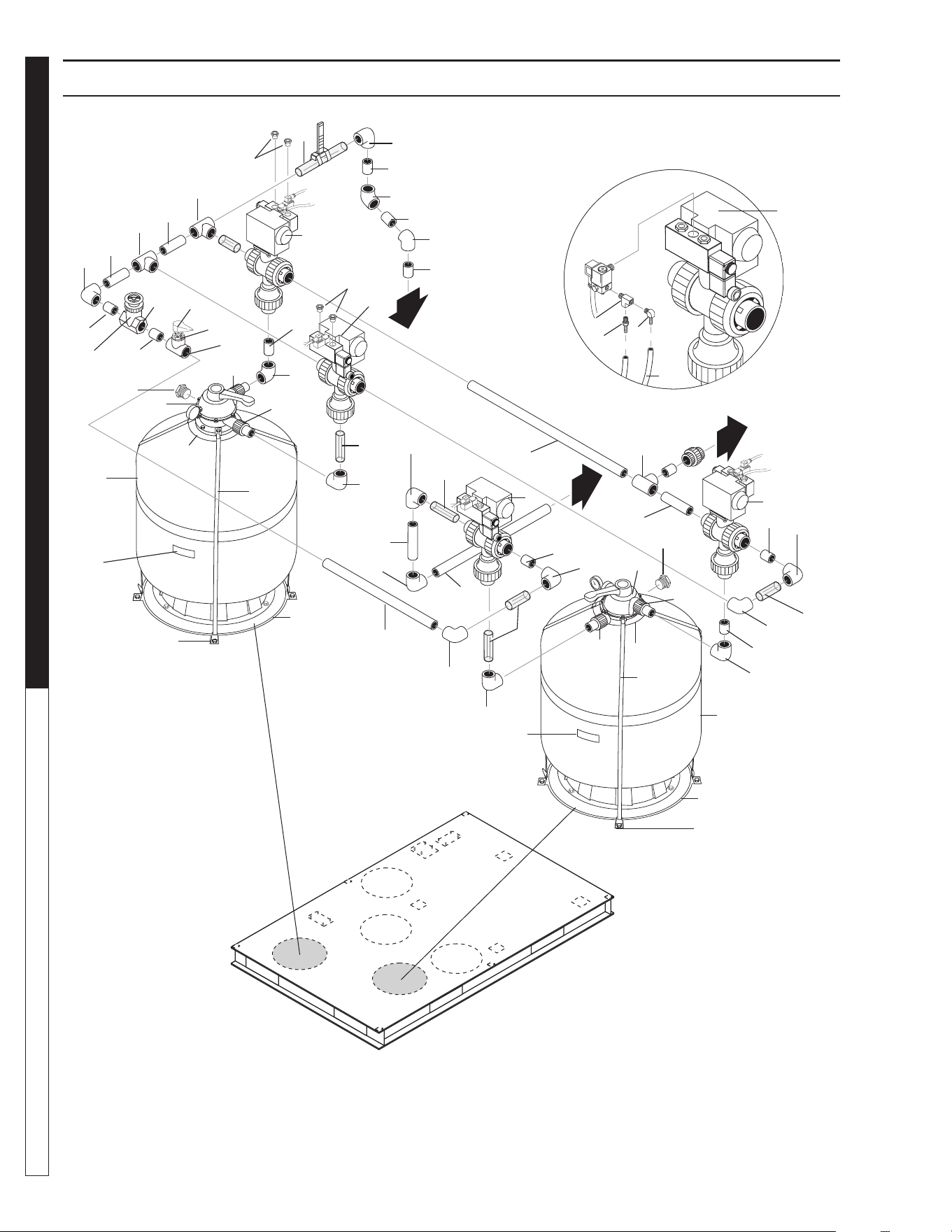
8.913-970.0 - L • WATERMAZE CLP 5024/7034
OPERATOR’S MANUAL WATER TREATMENT SYSTEM
42
CLP-5024 FILTER PLUMBING EXPLODED VIEW
89139700-9
13
14
8
Multimedia
Filter
Carbon
Filter
2
12
3
4
12
12
11
19
2
3
12
10
10
10
1, 22
5
12
11
12
12
10
10
10
12
12
5
10
11
10
14
10
14
10
11
5
6
10
10
12
10
13
Valve 21
17
16
15
4
10
12
5
5
11
12
10
18
7
8
9
10
1, 22
21
23
23
24
23
23
24
21
15
15
15
25
25
26
26

8.913-970.0 - L • WATERMAZE CLP 5024/7034
43
WATER TREATMENT SYSTEM
OPERATOR’S MANUAL
CLP-5024 FILTER PLUMBING EXPLODED VIEW PARTS LIST
ITEM PART NO. DESCRIPTION QTY
1 8.911-223.0 Mounting Tab, Filter 8
2 8.726-028.0 Filter Tank, , 3.1 sq-ft,
w/Valve, CF-II 2
3 8.726-030.0 Valve, 6 Pos,1-1/2" Ports 2
4 8.709-342.0 Strap, 84", Filter 8
5 8.749-845.0 Valve, 3 Way Diverter
w/Actuator 4
6 8.706-857.0 Tee, 1/8" Street 4
7 8.706-940.0 Hose Barb, 1/4" Barb x 1/8"
ML Pipe 4
8 8.706-955.0 Hose Barb 1/4" Barb x 1/8"
ML Pipe, 90 4
9 9.802-254.0 Hose 1/4" 20 ft
10 8.706-367.0 Pipe, 1.5", PVC 80, /ft 6 ft
11 8.706-360.0 Pipe, 1.5" PVC Clear, /ft 3.5 ft
12 8.706-374.0 Elbow,
1 1/2" S x S, PVC 80,
90°
12
13 8.707-344.0 Valve, PVC 1.5" SLIP x SLIP,
Gate 1
14 8.706-379.0 Elbow, 1-1/2" SLIP x SLIP,
PVC 80, 45 2
15 8.706-426.0 Tee, 1.5" S x S x S, PVC 80 3
16 8.706-914.0 Bushing, 1/2" x 1/8" Pipe 1
17 8.706-406.0 Bushing 1-1/2" x 1/2" SPG X FT,
PVC 80 Spearo 1
18 8.900-451.0 Label, Multi-media Filter 1
19 8.900-454.0 Label, Carbasorb Filter 1
20 8.718-920.0 ▲ Sand, 20-40, 50 Lb. Bag,
( Sold By The Lb) 50
8.718-921.0 ▲ Gravel, 50 Lb Bag,1/8 x 1/4,
(Sold By The Lb) 100
8.718-922.0 ▲ Anthracite #1 .60-.80mm,
50 # /Bag 25
8.718-923.0 ▲ Garnet,
30 x 40, 100 Lb /Bag
50
8.718-924.0 ▲ Garnet, 8 x 12, 100 Lb /Bag 50
8.718-933.0 ▲ Carbon, Virgin Coconut
8 x 30 (50 Lb /bag) 150
21 8.709-340.0 Strap, Hold Down, Neck 2
22 9.802-788.0 Nut, 3/8" Whiz Loc, SS 8
23 8.750-270.0 Fitting, Comp,
1-1/2" S x 1-1/2" MBT 4
24 8.706-394.0 Plug, 1-1/2", PVC 2
25 8.917-819.0 Ring Assy, Filter Base, 19.6" 2
26 8.756- 650.0 Muffl er, Exhaust 8
▲ Not Shown
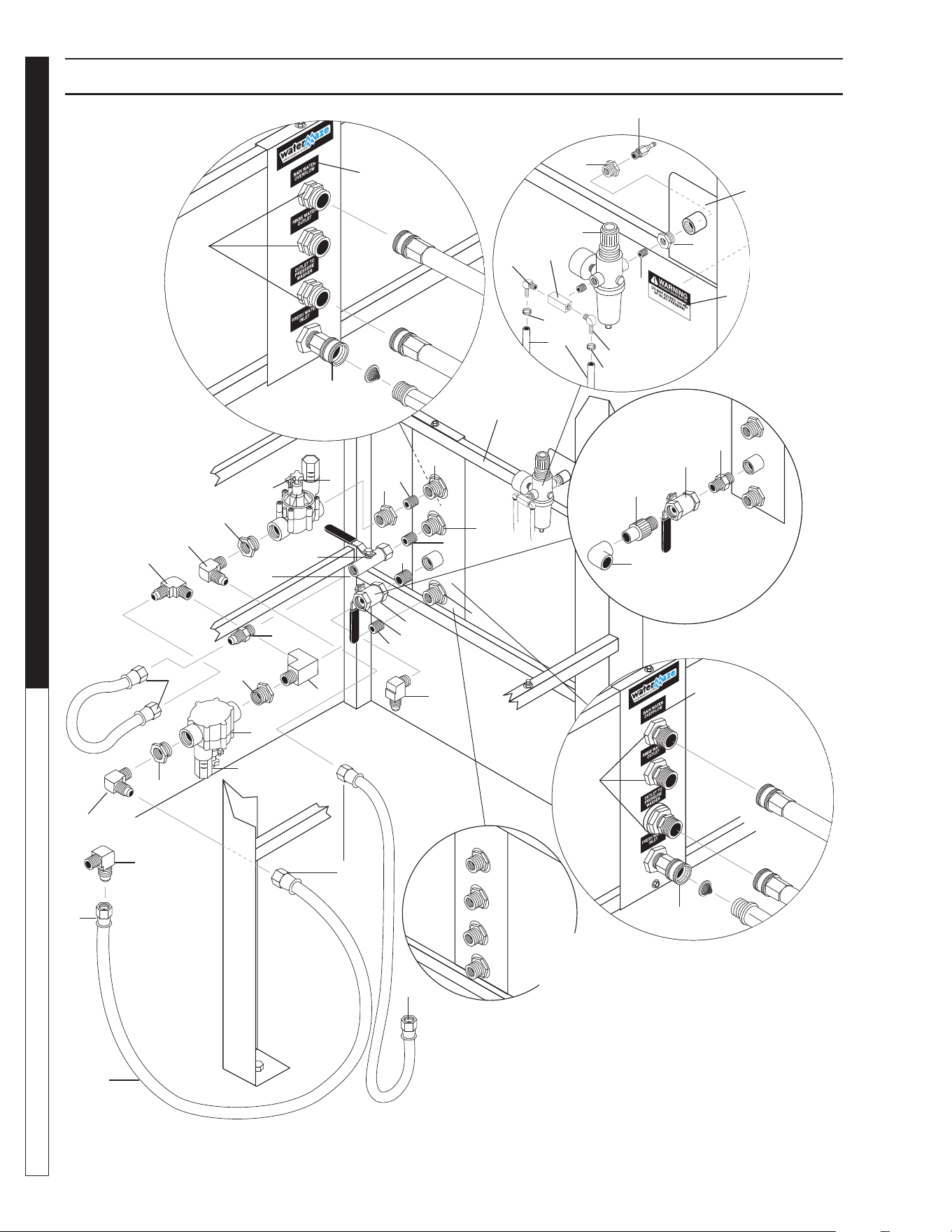
8.913-970.0 - L • WATERMAZE CLP 5024/7034
OPERATOR’S MANUAL WATER TREATMENT SYSTEM
44
89139700-36
CLP-5024/7034 WATER PANEL PLUMBING EXPLODED VIEW
15
20
28
Air Valve
Assy
25
26
21
23
23
24
27
22
Reversed
View of
Label
29
26
25
To Customer Supplied
Air Compressor
16
11
14
17
CLP-7034
(Reverse View)
CLP-7034
Water Panel
(Front View)
CLP-5024
Water Panel
(Front View)
To Manifold
Assy.
To Vertical
Holding
Tank #2
To Manifold
Assy.
Valve 16
SV1
SV2
10
19
12
2
5
6
3
5
5
18
2
1
Valve 7
13
3
11
2
31
4
7
Valve 8
Valve 6
1
30
18
2
8
10
19
13
9
9
13
9
14
CLP-5024 Water
Panel (Front View)
12

8.913-970.0 - L • WATERMAZE CLP 5024/7034
45
WATER TREATMENT SYSTEM
OPERATOR’S MANUAL
CLP-5024/7034 WATER PANEL PLUMBING PARTS LIST
ITEM PART NO. DESCRIPTION QTY
1 6-140166 Solenoid, Water Maze
PVC 24V 2
2 8.706-928.0 Bushing, 1" x 1/2" Black Poly 4
3 9.803-557.0 Elbow, 3/4" SAE x 3/4", 90° 2
4 9.802-128.0 Nipple, 1/2" JIC x 1/2" Pipe 1
5 9.802-152.0 Swivel, 3/4" SAE Fem,
Push-on 6
6 9.802-261.0 Hose, 3/4", Push-on 28 ft.
7 8.706-860.0 Tee, 1/2" Street Brass 1
8 8.707-211.0 Valve, 1/2" 8201 Brass Ball
400 PSI 1
9 8.707-000.0 Connector, 1/2" Anchor 3
10 8.706-968.0 Fitting, 3/4"
Grdn Hs x 1/2" Male 3
11 8.707-214.0 Valve, 3/4" 8201 Brass Ball
CLP-5024 1
8.707-233.0 Valve, 1",
Brass Ball, CLP-7034
1
12 9.802-146.0 Swivel, 1/2" MP x 3/4" GHF
w/Strainer 1
13 8.706-790.0 Nipple, 1/2" Close 3
14 8.706-801.0 Nipple, 1" Close, Brass,
CLP-7034 1
8.706-881.0 Nipple, 3/4" Pipe x 1/2" Pipe,
CLP-5024 1
15 8.913-102.0 Panel, Water CLP-7034 1
8.913-103.0 Panel, Water CLP-5024 1
ITEM PART NO. DESCRIPTION QTY
16 8.706-409.0 Adapter, 1" MT x Slip, PVC 80
CLP-7034 1
17 8.706-373.0 Elbow, 1" S x S, PVC 80, 90°
CLP-7034 1
18 9.802-132.0 Elbow, 3/4" JIC x 1/2", 90° 3
19 8.900-520.0 Label, Water Connection
Panel CLP 1
20 8.707-177.0 Nipple, 1/4" Mal Air 1
21 8.707-331.0 Regulator, Air w/Filter,
1/4" Gauge 1
22 8.706-777.0 Nipple, 1/4" Close 1
23 8.706-915.0 Bushing, 1/2" x 1/4" Brass 2
24 9.802-961.0 Hose Connection Bracket 1
25 8.706-958.0 Hose Barb, 1/4" Barb x 1/4"
Pipe 90° 2
26 6.390-126.0 Clamp, Hose, UNI .46-.54 2
27 8.900-210.0 Label, Warning, 100 PSI
Air Pressure 1
28 8.706-854.0 Tee, 1/4" Branch, Male 1
29 4-02100000 Hose, 1/4" Push-on 10 ft
30 9.802-129.0 Elbow, 1/2" JIC x 38", 90° 1
31 9.802-151.0 Swivel, 1/2" JIC Fem,
Push-On 2
32 9.802-254.0 Hose, 1/2" Push-On 1.5 ft
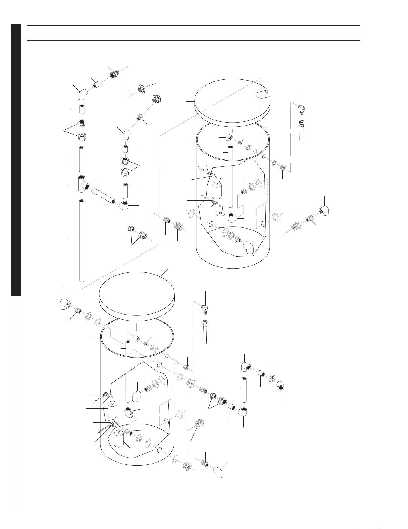
8.913-970.0 - L • WATERMAZE CLP 5024/7034
OPERATOR’S MANUAL WATER TREATMENT SYSTEM
46
CLP-7034 HOLDING TANK PLUMBING EXPLODED VIEW
89139700-20
5
6
4
6
3
6
6
4
6
7
24
25
2
6
3
21
7
12
11
26
6
10
11
19
9
12
24
25
12
25
24
10
11
20
22
23
15
16
8
14
16
6
17
19
11
18
9
9
26
8
23
6
22
16
16
14
15
24
25
11
10
20
12
25
24
21
To Recycle
#2 Solenoid
To Main
Drain Assy.
CLP-7034 Vertical
Storage Tank #1
To Fresh Water
Make-Up
To Carbon Filter
Assembly
To Transfer
Pump
To Main Drain
Assembly
CLP-7034 Vertical
Storage Tank #2
To Filter
Pump
1 - To
Main Tank
Assembly
27
27
27
27

8.913-970.0 - L • WATERMAZE CLP 5024/7034
47
WATER TREATMENT SYSTEM
OPERATOR’S MANUAL
CLP-7034 HOLDING TANK PLUMBING PARTS LIST
ITEM PART NO. DESCRIPTION QTY
1 8.706-479.0 Bulkhead, 2", NPT, Polypro 2
2 8.706-451.0 Adapter, 2", S x MT, PVC 80 2
3 8.706-382.0 Elbow, 2", S x S, PVC 80, 90° 2
4 8.706-473.0 Union, 2", S x S, PVC 80 2
5 8.706-434.0 Tee, 2", S x S x S, PVC 80 1
6 8.706-583.0 Pipe, 2", Gray, PVC 80 10 ft.
7 8.719-171.0 Lid, 22" Tank, 65 Gallon 2
8 8.719-170.0 Tank, Vertical, 65 Gallon 2
9 8.706-367.0 Pipe, 1-1/2", PVC 80 2 ft.
10 8.706-372.0 Elbow, 1-1/2", S x T,
PVC 80, 90° 3
11 8.706-424.0 Nipple, 1-1/2" x Close, PVC 80 5
ITEM PART NO. DESCRIPTION QTY
12 8.706-490.0 Bulkhead, 1-1/2" Polypro 5
13 8.706-441.0 Adapter, 1-1/2", S x MT 4
14 8.716-143.0 Switch, Float, N/C 2
15 8.716-142.0 Switch, Float, N/O 2
16 9.802-514.0 Strain Relief 4
17 8.706-379.0 Elbow, 1-1/2", S x S, 45° 1
18 8.706-487.0 Hanger, 2" Pipe 1
19 8.706-374.0 Elbow, 1-1/2", S x S, 90° 2
20 9.802-052.0 Bulkhead, 3/4" Polypro 2
21 9.803-557.0 Elbow, 3/4" x 3/4", 90°, Brass 2
22 8.706-369.0 Nipple, 3/4", PVC 80, Close 2
23 8.706-377.0 Elbow, 3/4" FIPT x FIPT, 90° 2
24 8.706-384.0 Elbow, 2" S x FPT 5
25 8.706-466.0 Nipple, 2" Close 5
26 8.706-470.0 Union, 1-1/2" S x T 2
27 8.750-743.0 Bulkhead, 1/2" Polypro 4
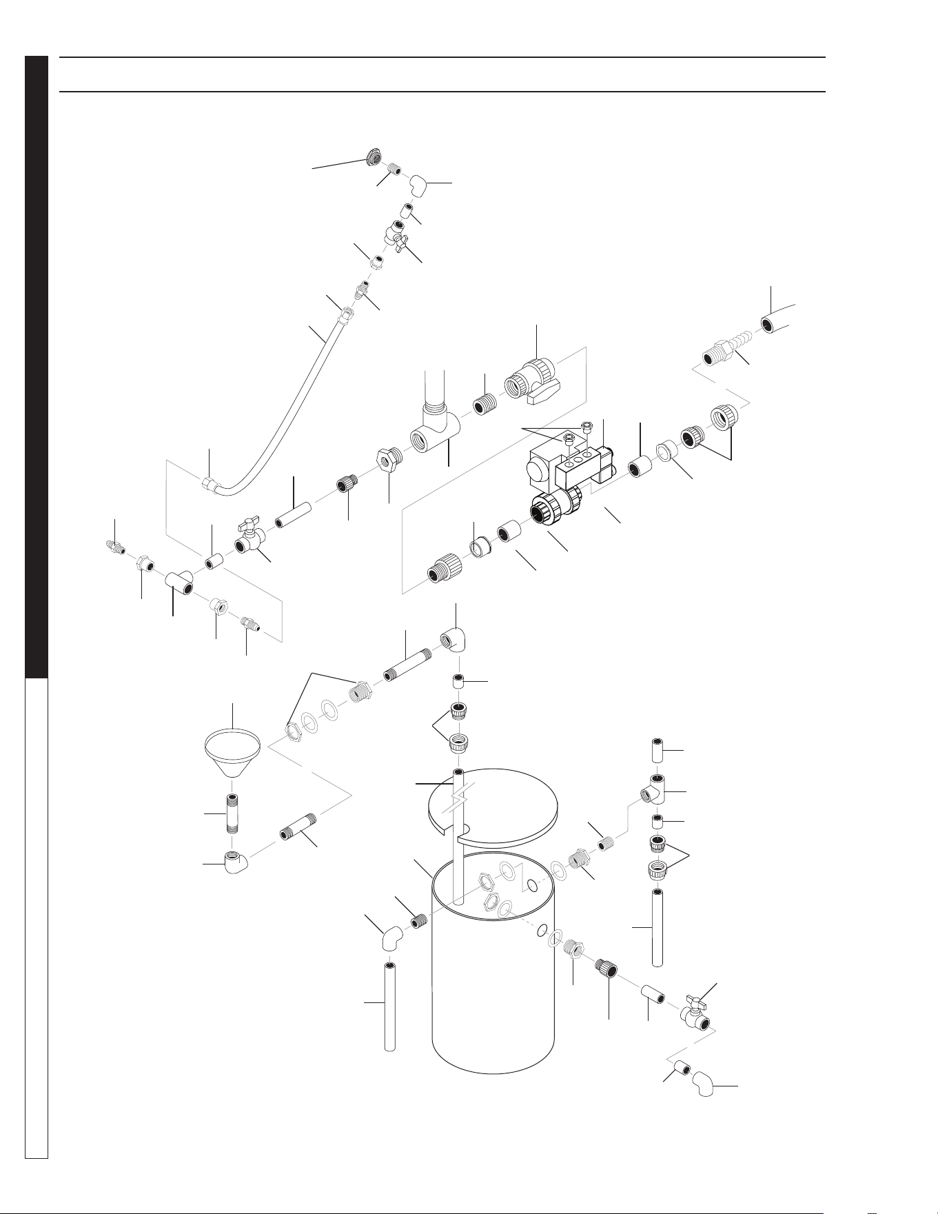
8.913-970.0 - L • WATERMAZE CLP 5024/7034
OPERATOR’S MANUAL WATER TREATMENT SYSTEM
48
CLP-7034 TANK DRAIN/OIL SKIMMER PLUMBING EXPLODED VIEW
89139700-30
4
15
13
37
10
30
16
8
5
14
30
12
11
12
13
30
10
19
23
24
25
21
28
29
7
6
21
35
23
22
27
25
20
21
22
25
22
26
25
24
23
25
36
10
25
25
25
3
31
38
38
1
32
31
33
17 - To 600
Gallon Main Tank
Bottom
To Main Tank
Bottom Cone
13 - To
Manifold Assy.
34 - To Sludge
Tub
14
2
39
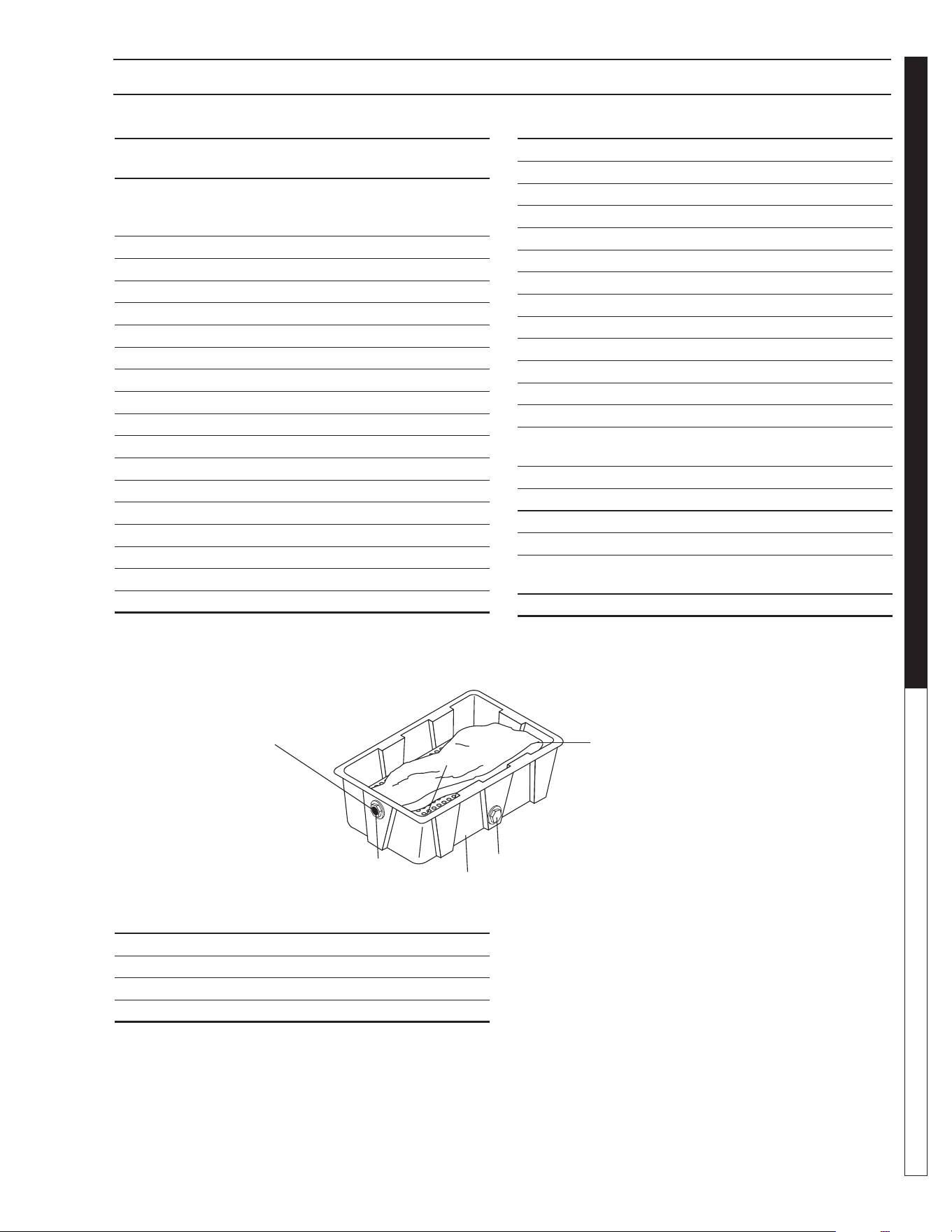
8.913-970.0 - L • WATERMAZE CLP 5024/7034
49
WATER TREATMENT SYSTEM
OPERATOR’S MANUAL
CLP-7034 TANK DRAIN/OIL SKIMMER PLUMBING
PARTS LIST
ITEM PART NO. DESCRIPTION QTY
1 8.756-648.0 VALVE, BALL, 1-1/2", PNEU ACT,
NO SOL 1
2 8.756-462.0 SOLENOID, VALVE, 24VAC,
SV61 1
8.706-777.0 ▲ Nipple, 1/4" Close 1
3 8.706-451.0 Adapter, 2", S x MT 2
4 8.707-349.0 Valve, 2", Single Union Ball 1
5 8.706-466.0 Nipple, 2" Close 1
6 8.706-436.0 Tee, 2", T x T x T 1
7 8.706-418.0 Bushing, 2" x 1", MPT x FPT 1
8 8.706-439.0 Nipple, 1" Close 2
9 8.706-444.0 Adapter, Female, 1", S x FT 1
10 8.707-359.0 Valve, 1" Molded 3
11 8.706-430.0 Tee, 1", S x S x S 1
12 8.706-447.0 Adapter, 1", 3/4" S x FIPT 2
13 8.706-899.0 Nipple, 3/4" JIC x 3/4" Pipe 2
14 9.802-152.0 Swivel, 3/4" SAE, Female 2
15 9.802-261.0 Hose, 3/4" Push-On 3 ft.
16 8.706-378.0 Elbow, 1", S x FT 1
17 8.706-484.0 Bulkhead, 1", PolyPro 1
18 8.711-817.0 Hose, 2" Clear Spiralite 8 ft.
19 8.706-683.0 Funnel, Plastic Oil Skimmer 1
ITEM PART NO. DESCRIPTION QTY
20 8.706-482.0 Nipple, 1-1/2" x 6", PVC 80 1
21 8.706-372.0 Elbow, 1/12" S x T 3
22 8.706-424.0 Nipple, 1-1/2" Close 5
23 8.706-490.0 Bulkhead, 1-1/2" Polypro 3
24 8.706-469.0 Union, 1-1/2" S x S 2
25 8.706-367.0 Pipe, 1-1/2" PVC 80 8 ft.
26 8.706-428.0 Tee, 1-1/2", S x S x T 1
27 8.719-169.0 Tank, Vertical, w/Lid, 26 Gallon 1
28 8.706-482.0 Nipple, 1-1/2" x 6" 1
29 8.706-409.0 Adapter, 1" S x MT 1
30 8.706-366.0 Pipe, 1", PVC 80 1 ft.
31 8.706-367.0 Pipe, 1.5", PVC 80 1 ft.
32 8.706-476.0 Union, 2", FS x FT 1
33 8.706-453.0 Adapter, 2" MT x 2", Hose
Insert 1
34 8.711-817.0 Hose, 2" Clear, Spiralite 3 ft.
35 8.706-441.0 Adapter, 1.5" S x MT 1
36 8.706-374.0 Elbow, 1.5" S x S 1
37 8.706-447.0 Adapter, 1", 3/4" S x FIPT 1
38 8.706-413.0 BUSHING, 2' X 1 1/2' SLIP,
PVC 80 2
39 8.756- 650.0 Muffl er, Exhaust 2
▲ Not Shown
1
4
ITEM PART NO. DESCRIPTION QTY
1 8.719-191.0 Sludge Bags 5
2 8.913-094.0 Support, Sludge Bag 1
3 8.719-179.0 Sludge Tub, w/Lid 1
4 8.706-479.0 Bulkhead 2" NPT Polypro 2
Sludge
Tub
4
3
2
Drill hole with 3" hole saw
4.5" from top lip of sludge tub
to center of bulkhead.
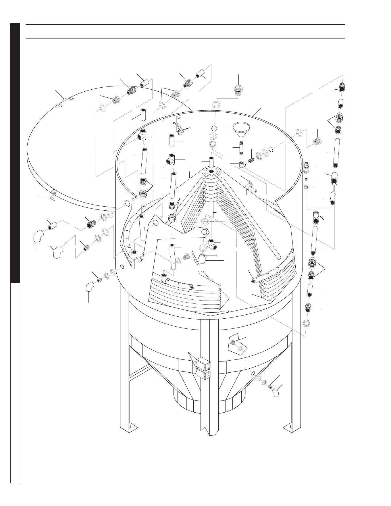
8.913-970.0 - L • WATERMAZE CLP 5024/7034
OPERATOR’S MANUAL WATER TREATMENT SYSTEM
50
CLP-7034 MAIN TANK PLUMBING EXPLODED VIEW
89139700-22
31
2
24
22
27
1
26
19
5
14
12
37
36
10
13
10
14
12
12
15
16
12
15
32
16
9
2
6
35
13
5
12
18
10
17
15
10
22
20
22
28
11
11
23
24
10
5
4
21
5
3
24
23
5
2
4
5
6
8
5
34
33
7
30
25
3

8.913-970.0 - L • WATERMAZE CLP 5024/7034
51
WATER TREATMENT SYSTEM
OPERATOR’S MANUAL
CLP-7034 MAIN TANK PLUMBING EXPLODED VIEW PARTS LIST
ITEM PART NO. DESCRIPTION QTY
1 8.706-424.0 Nipple, 1-1/2" Close 1
2 8.706-490.0 Bulkhead, 1-1/2" Polypro 3
3 8.706-441.0 Adapter, 1-1/2" S x MT 2
4 8.706-469.0 Union, 1-1/2" S x S 2
5 8.706-367.0 Pipe, 1-1/2" PVC 80 6 ft.
6 8.706-426.0 Tee, 1-1/2", S x S x S 2
7 8.706-428.0 Tee, 1-1/2", S x S x T 1
8 8.707-298.0 Valve, 1/2" Ball Check 1
9 8.706-394.0 Plug, 1-1/2" PVC 80 1
10 8.711-816.0 Hose, 2" Gray Conduit 16 ft.
11 8.706-382.0 Elbow, 2" S x S 2
12 8.706-583.0 Pipe, 2" PVC 80 .5 ft.
13 8.706-473.0 Union, 2", S x S 2
14 8.706-434.0 Tee, 2" S x S x S 2
15 8.706-451.0 Adapter, 2" S x MT 3
16 8.706-479.0 Bulkhead, 2" NPT, Polypro 2
17 8.706-466.0 Nipple, 2" Close 1
18 8.706-384.0 Elbow, 2" S x FPT 1
19 8.706-677.0 Cone, 3/16", Vertical Coalescing,
w/Holes 1
20 8.706-679.0 Cone, 1/8", Vertical Coalescing,
w/Holes 8
21 8.706-678.0 Cone, 1/8", Vertical Coalescing,
No Holes 1
22 8.706-484.0 Bulkhead, 1" Polypro 3
23 8.706-439.0 Nipple, 1" Close 2
ITEM PART NO. DESCRIPTION QTY
24 8.706-378.0 Elbow, 1" S x T 3
25 8.706-683.0 Funnel, Plastic Oil Skimmer 1
26 8.706-482.0 Nipple, 1-1/2" x 6", PVC 80 1
27 8.706-375.0 Elbow, 1-1/2" FT x FT 1
28 8.716-324.0 Box, Junction, 1/2", 4-Hole
(CLP-7034A) 2
(CLP-7034B,C) 1
8.716-323.0 Box, Junction, 5 Hole
(CLP-7034B,C) 1
29 9.802-483.0 Cover Plate, Junction Box 2
30 8.719-177.0 Tank, Clarifi er 600 w/Lid 1
31 8.706-648.0 Handle 2
32 8.706-568.0 Handle, Rubber T, w/Keeper 3
33 8.706-406.0 Bushing, 1-1/2" x 1/2" 1
34 8.706-467.0 Nipple, 1/2" Close 1
35 8.706-382.0 Elbow, 2" S x S 1
36 8.913-085.0 Bracket, ORP/pH 1
37 8.716-905.0 Sensor, pH 1
8.716-906.0 Sensor, ORP 1
8.900-803.0 ▲ Label, WaterMaze 1
▲ Not Shown
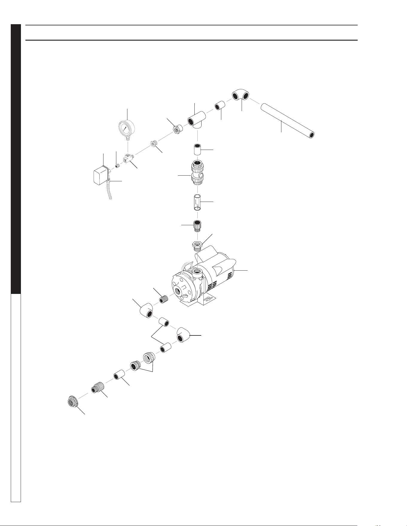
8.913-970.0 - L • WATERMAZE CLP 5024/7034
OPERATOR’S MANUAL WATER TREATMENT SYSTEM
52
CLP-7034 TRANSFER PUMP PLUMBING EXPLODED VIEW
89139700-32
20
16
17
15
7
18
14
13
12
24
3
20
20
19
22
5
4
6
2
21
9
23
1
10
4

8.913-970.0 - L • WATERMAZE CLP 5024/7034
53
WATER TREATMENT SYSTEM
OPERATOR’S MANUAL
CLP-7034 TRANSFER PUMP PLUMBING PARTS LIST
ITEM PART NO. DESCRIPTION QTY
1 8.706-490.0 Bulkhead, 1-1/2" Polypro 1
2 8.706-424.0 Nipple, 1-1/2" x Close, PVC 80 2
3 8.707-300.0 Valve, 1", Ball Check 1
4 8.706-367.0 Pipe, 1-1/2" PVC 80 .5 ft.
5 8.706-374.0 Elbow, 1-1/2" S x S,
PVC 80, 90° 1
6 8.706-372.0 Elbow, 1-1/2" S x T,
PVC 80, 90° 1
7 8.712-154.0 Gauge, Pressure 0-100, 1/4" 1
8 8.706-469.0 Union, 1.5" S x S 1
9 8.706-405.0 Bushing, 1-1/4" x 1" MT x FT,
PVC 80 1
10 8.706-441.0 Adapter, 1-1/2" Slip x MT,
PVC 80 1
11 8.706-439.0 Nipple, 1" Close 1
12 8.706-430.0 Tee, 1" S x S, PVC 80 1
ITEM PART NO. DESCRIPTION QTY
13 8.706-447.0 Adapter, 1", 3/4" S x FIPT,
PVC 80 1
14 8.706-923.0 Bushing, 3/4" x 1/4" Pipe 1
15 8.706-777.0 Nipple, 1/4" Close 1
16 8.716-154.0 Switch, Pressure 1
9.802-105.0 ▲ Plug, 7/8" Hole 1
17 9.802-517.0 Connector, 1/2" L/T, 90° 1
18 8.706-858.0 Tee, 1/4" Street 1
19 8.706-373.0 Elbow, 1" S x S, PVC 80,
90° 2
20 8.706-366.0 Pipe, 1", PVC 80 1 ft.
21 8.715-402.0 Pump, Scot 2 HP, 208/230V
1PH, CLP-7034A 1
8.715-404.0 Pump, Scot 2 HP,
208/230/460V
3 PH, CLP7034B, C 1
22 8.706-469.0 Union, 1-1/2" Slip x Slip 1
23 8.706-409.0 Adapter, 1" MT x Slip 1
24 8.706-361.0 Pipe, 1" Clear PVC .25 ft.
▲ Not Shown
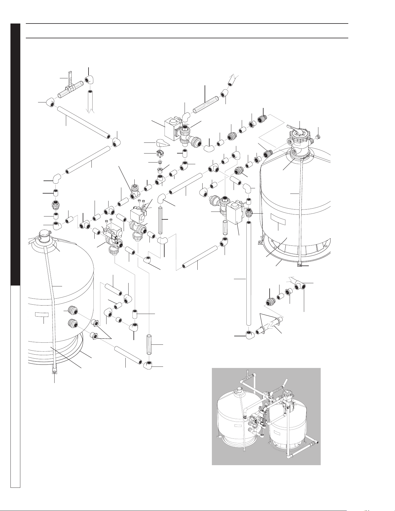
8.913-970.0 - L • WATERMAZE CLP 5024/7034
OPERATOR’S MANUAL WATER TREATMENT SYSTEM
54
89139700-37
CLP-7034 CARBON/MULTI MEDIA FILTER PLUMBING EXP. VIEW
1
23
5
2
5
5
5
5
2
4
5
5
4
2
3
5
5
8
25
5
13
15
9
5
19
11
12
5
7
14
5
5
18
4
14
5
5
1
5
3
5
20
21, 28
24
To Main Drain
Assembly
1
16
5
30
1
1
1
5
1
13
32
26
14
14
20
22
10
5
1
21, 28
13
3
1
5
5
5
1
1
1
5
1
1
1
5
1
5
1
6
1
16
2
5
1
5
27
13
1
17
18
Valve 21
Carbon Filter
Multi Media
Filter
15
15
29
31
31

8.913-970.0 - L • WATERMAZE CLP 5024/7034
55
WATER TREATMENT SYSTEM
OPERATOR’S MANUAL
CLP-7034 CARBON/MULTI MEDIA FILTER PLUMBING PARTS LIST
ITEM PART NO. DESCRIPTION QTY
1 8.706-374.0 Elbow, 1-1/2" S x S, PVC 80 20
2 8.706-469.0 Union, 1-1/2" S x S 5
3 8.706-360.0 Pipe, 1-1/2" Clear PVC 6 ft.
4 8.706-426.0 Tee, 1-1/2" S x S x S, PVC 80 2
5 8.706-367.0 Pipe, 1-1/2" PVC 80 20 ft.
6 8.706-379.0 Elbow, 1-1/2" S x S, 45° 1
7 8.706-406.0 Bushing, 1-1/2" x 1/2"
SPG x FT 1
8 8.706-914.0 Bushing, 1/2" x 1/8" 1
9 8.716-158.0 Switch, Pressure, 15 PSI 1
10 8.716-157.0 Protector, Pressure Switch 1
11 8.712-136.0 Gauge, Flow (Incl 2 Clamps) 1
12 8.706-421.0 Hanger, Pipe, 1-1/2" 2
13 8.749-845.0 Valve, 3-Way Diverter
w/Actuator 4
14 8.716-425.0 Valve, Solenoid, 24V 4
- 8.756-650.0 Muffl er, Exhaust 8
15 8.706-413.0 Bushing, 2" x 1-1/2", S x S 3
16 8.706-451.0 Adapter, 2" S x T 2
17 8.707-344.0 Valve, PVC Gate, 1-1/2" S x S 1
18 8.706-434.0 Tee, 2" S x S x S 1
19 8.709-342.0 Strap, Filter, 84" 4
20 8.709-340.0 Strap, Hold Down, Neck 2
21 8.911-223.0 Mounting Tab 8
22 8.900-451.0 ▲ Label, Multi-Media Filter 1
23 8.900-454.0 Label, Carbasorb Filter 1
24 8.753-260.0 Union, 2" Triton Filter 2
25 8.726-029.0 Filter, 4.9 Sq. Ft. Carbon Tank,
w/Valve 1
8.718-933.0 ▲ Carbon, Activated 190 lbs.
26 8.723-203.0 Filter, Media Tank, 7.1 Sq. Ft. 1
27 8.723-031.0 Valve, 6 Position, 2" Ports 1
28 9.802-788.0 Nut, 3/8" Whiz Loc, SS 8
29 8.706-395.0 Plug, 2", PVC 80 1
30 8.709-339.0 Strap, Filter, 112" 4
31 8.913-318.0 Assy, Ring, Filter Base, 25" 2
32 8.706-413.0 Bushing, 2" x 1-1/2" Slip,
PVC 80 2
▲ Not Shown
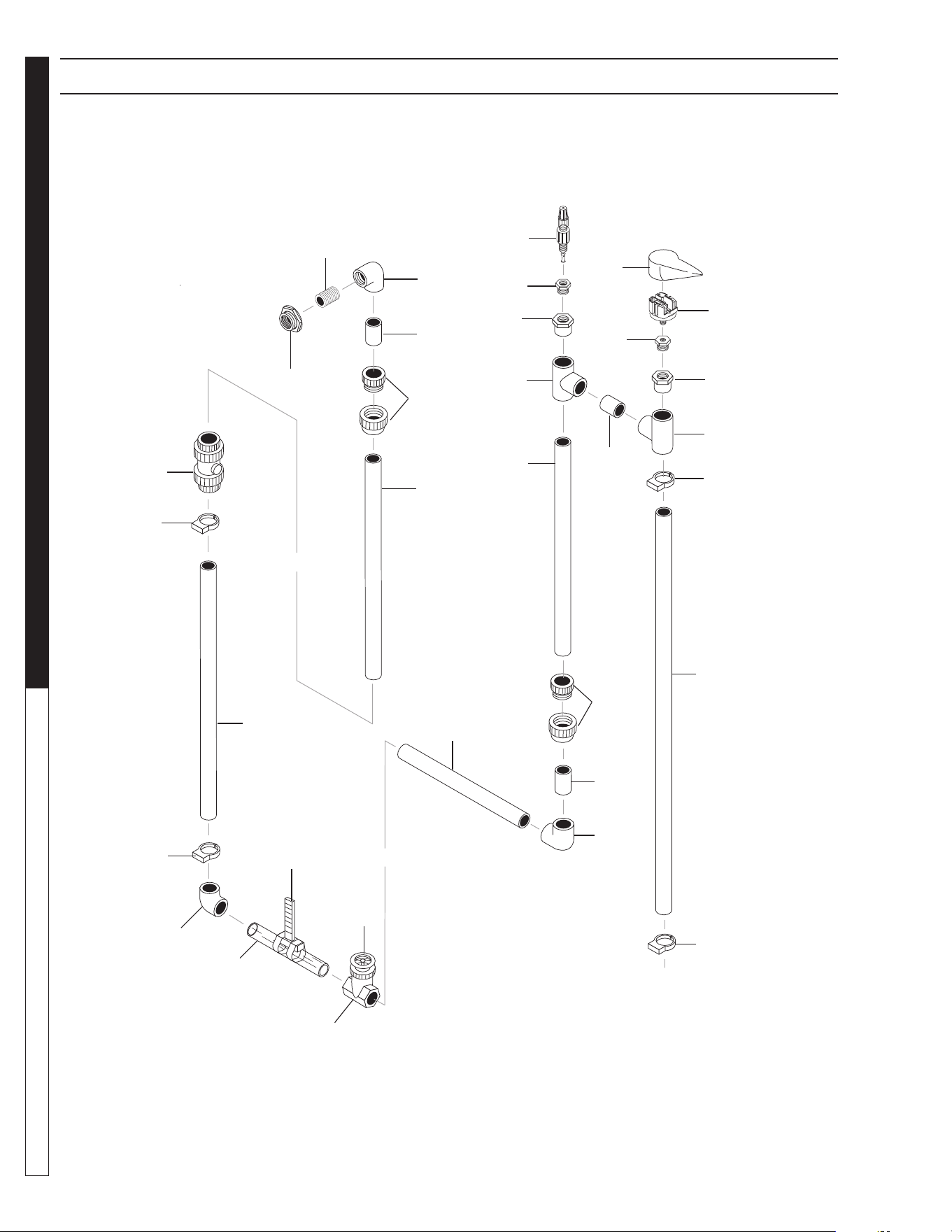
8.913-970.0 - L • WATERMAZE CLP 5024/7034
OPERATOR’S MANUAL WATER TREATMENT SYSTEM
56
CLP-7034 FLOW METER PLUMBING EXPLODED VIEW
89139700-19
8
7
6
5
4
2
3
3
4
5
9
10
3
11
3
16
3
2
1
3
11
2
3
1
14
13
12
2
18
17
15
Valve 1

8.913-970.0 - L • WATERMAZE CLP 5024/7034
57
WATER TREATMENT SYSTEM
OPERATOR’S MANUAL
CLP-7034 FLOW METER PLUMBING PARTS LIST
ITEM PART NO. DESCRIPTION QTY
1 8.706-374.0 Elbow, 1-1/2" S x S,
PVC 80, 90° 2
2 8.706-421.0 Hanger, Pipe, 1-1/2" 4
8.913-083.0 ▲ Spacer, Pipe Clip 4
9.803-674.0 ▲ Screw, 8/32", Keps 4
9.802-785.0 ▲ Nut, 8/32", Keps 4
3 8.706-367.0 Pipe, 1-1/2", PVC 80 10 ft.
4 8.706-426.0 Tee, S x S x S, 1-1/2" 2
5 8.706-406.0 Bushing, 1-1/2" x 1/2" SPG x FT,
PVC 80 2
6 8.706-914.0 Bushing, 1/2" x 1/8" 1
7 8.716-156.0 Switch, Pressure, 1 PSI 1
8 8.716-157.0 Protector, Pressure Switch 1
9 8.706-407.0 Bushing, 1/2" x 1/4" PVC 80 1
ITEM PART NO. DESCRIPTION QTY
10 8.716-986.0 Injector 1
11 8.706-469.0 Union, 1-1/2" S x S, PVC 80 2
12 8.707-344.0 Valve, 1-1/2" S x S, PVC Gate 1
13 8.712-136.0 Gauge, Flow Meter (Includes 2
Clamps) 1
14 8.706-360.0 Pipe, 1-1/2" Clear PVC 1 ft.
15 8.707-299.0 Valve, 1-1/2" Swing Check 1
16 8.706-372.0 Elbow, 1-1/2" S x T, PVC 80,
90° 1
17 8.706-424.0 Nipple, 1-1/2" x Close, PVC 80 1
18 8.706-490.0 Bulkhead, 1-1/2" Polypro 1
▲ Not Shown
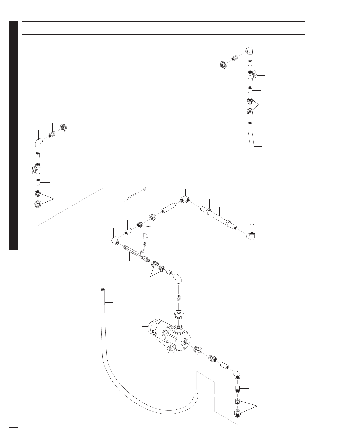
8.913-970.0 - L • WATERMAZE CLP 5024/7034
OPERATOR’S MANUAL WATER TREATMENT SYSTEM
58
CLP-7034 OZONE PUMP PLUMBING EXPLODED VIEW
89139700-27
13
12
17
8
18
11
18
9
18
5
6
8
18
7
9
18
10
16
9
18
10
2
17
8
14
18
3
18
2
1
9
9
13
11
8
12
17
18
18
16
15
4

8.913-970.0 - L • WATERMAZE CLP 5024/7034
59
WATER TREATMENT SYSTEM
OPERATOR’S MANUAL
CLP-7034 OZONE PUMP PLUMBING PARTS LIST
ITEM PART NO. DESCRIPTION QTY
1 8.917-760.0 Pump, Ozone, 3/4 HP,
(CLP-7034A) 1
8.723-219.0 ▲ Pump, Ozone, 3/4 HP,
(CLP-7034B,C) 1
2 8.706-418.0 Bushing, Reducer, 2" x 1",
PVC 80 (CLP-7034B, C) 2
8.706-404.0 Bushing, Reducer, 1-1/2" x 1",
PVC 80 (CLP-7034A) 2
3 8.706-409.0 Adapter, 1" MT x S, PVC 80 2
4 8.706-588.0 Connector, 3/8" x 1/4"
Male Elbow, Poly 1
5 8.709-431.0 Injector, Ozone 1
6 8.706-587.0 Nipple, 1/2" x 1/4", Hex 1
7 8.707-321.0 Valve, Ozone Meter 1
8 8.706-378.0 Elbow, 1" S x FIPT, 90° 4
9 8.706-597.0 Union, 1", S x S 6
ITEM PART NO. DESCRIPTION QTY
10 8.706-373.0 Elbow, 1", SLIP x FIPT, 90° 2
11 8.707-359.0 Valve, 1" 2
12 8.706-484.0 Bulkhead, 1" 2
13 8.711-812.0 Hose, 1", Gray Conduit 8 ft.
14 8.706-371.0 Elbow, 1", 45° 1
15 8.711-733.0 Tubing, 3/8" x 1/2", Vinyl, /ft. 10 ft.
16 8.706-423.0 Hanger, 1" Pipe 2
17 8.706-439.0 Nipple, 1" Close, PVC 4
18 8.706-361.0 Pipe, 1" PVC 3 ft.
▲ Not Shown
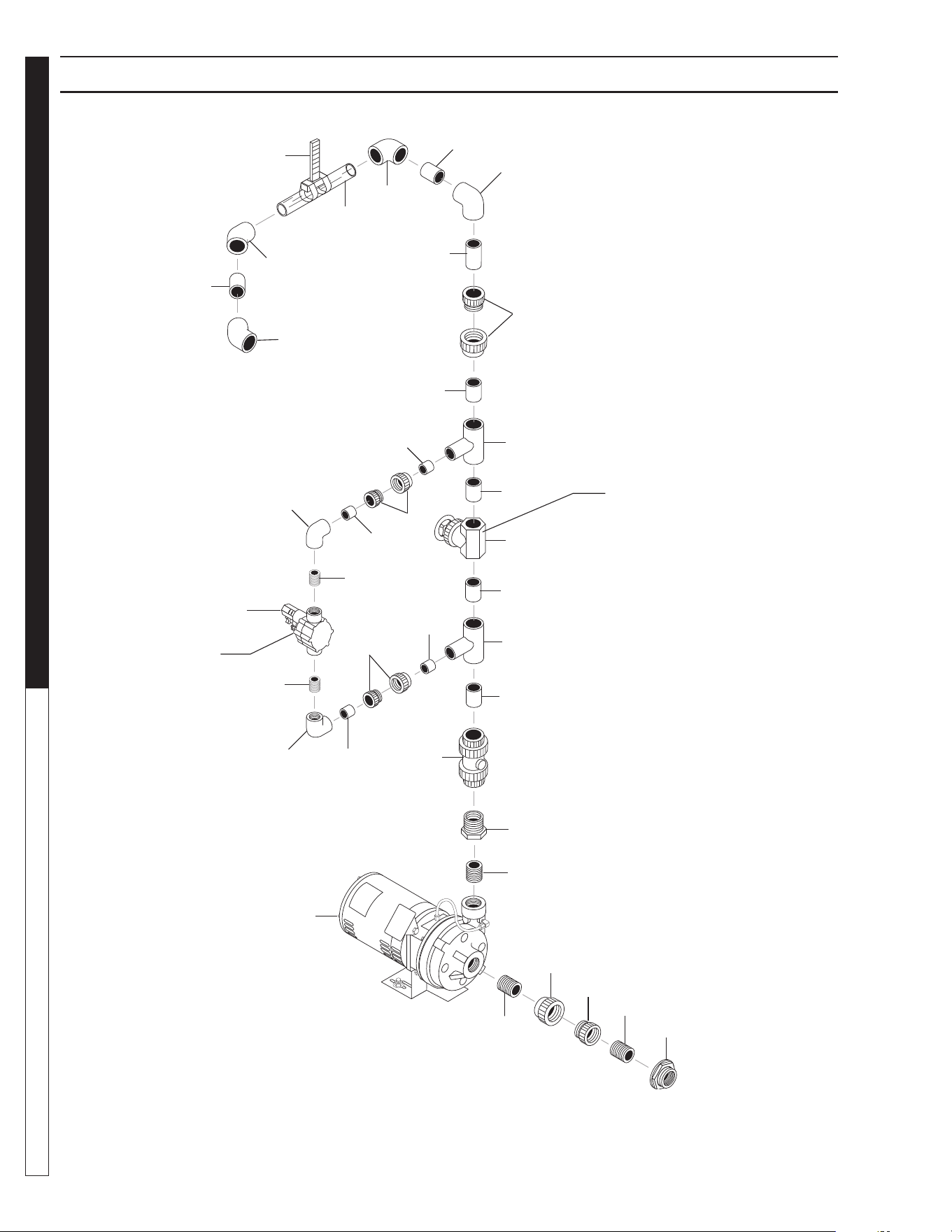
8.913-970.0 - L • WATERMAZE CLP 5024/7034
OPERATOR’S MANUAL WATER TREATMENT SYSTEM
60
CLP-7034 FILTER PUMP PLUMBING EXPLODED VIEW
89139700-18
1
6
20
4
5
2
3
3
2
10
12
11
10
13
14
13
12
10
11
10
8
7
9
7
8
7
7
19
18
19
17
16
7
16
7
15
7
Valve 10
Valve 20

8.913-970.0 - L • WATERMAZE CLP 5024/7034
61
WATER TREATMENT SYSTEM
OPERATOR’S MANUAL
CLP-7034 FILTER PUMP PLUMBING PARTS LIST
ITEM PART NO. DESCRIPTION QTY
1 8.706-490.0 Bulkhead, 1-1/2" Polypro 1
2 8.706-424.0 Nipple, 1-1/2" x Close, PVC 80 2
3 8.706-472.0 Union, 1-1/2" FT x FT, PVC 80 1
4 8.706-461.0 Nipple, 1-1/4" Close, PVC 80 1
5 8.706-415.0 Bushing, 1-1/2" MT x 1-1/4" FT,
PVC 80 1
6 8.707-297.0 Valve, 1-1/2" PVC Ball Check 1
7 8.706-367.0 Pipe, 1-1/2" PVC 80 1.5 ft.
8 8.706-431.0 Tee, 1-1/2" x 1-1/2" x 1" S,
PVC 80 2
9 8.707-344.0 Valve, 1-1/2" S x S, PVC Gate 1
10 8.706-366.0 Pipe, 1" PVC 80 .5 ft.
11 8.706-597.0 Union, 1", S x S, PVC 80 2
12 8.706-378.0 Elbow, 1" S x FIPT, PVC 80,
90° 2
ITEM PART NO. DESCRIPTION QTY
13 8.706-439.0 Nipple, 1", PVC 80, Close 2
14 8.716-697.0 Solenoid, PVC, 24 Volt 1
15 8.706-469.0 Union, 1-1/2" S x S, PVC 80 1
16 8.706-374.0 Elbow, 1-1/2" S x S, PVC 80,
90° 2
17 8.706-360.0 Pipe, 1-1/2" Clear PVC 1 ft.
18 8.712-136.0 Gauge, 1-1/2" Flow Meter 1
19 8.706-379.0 Elbow, 1-1/2" S x S, PVC 80,
45° 2
20 8.715-402.0 Pump, Filter 2 HP, 208/230V
1 PH (CLP-7034A) 1
8.715-404.0 Pump, Filter 2 HP,
208/230/460V
3 PH (CLP-7034B, C) 1
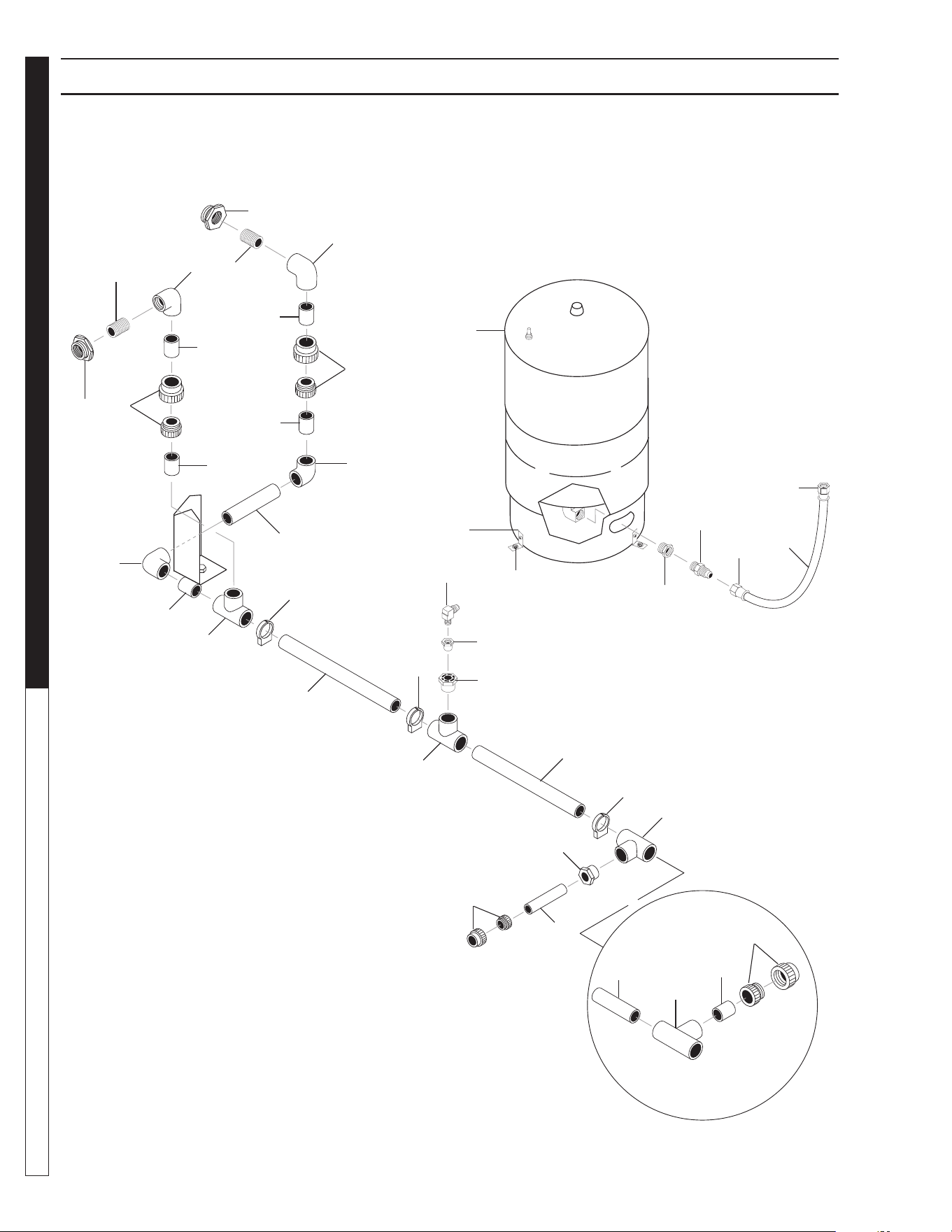
8.913-970.0 - L • WATERMAZE CLP 5024/7034
OPERATOR’S MANUAL WATER TREATMENT SYSTEM
62
CLP-7034 SURGE TANK/MAIN DRAIN PLUMBING EXP. VIEW
89139700-29
15
4
5
3
2
1
4
1
2
4
5
4
3
6
6
1
4
7
8
4
7
8
4
9
10
11
16
8
17
13
14
12
7
4
7
4
22
18
19
20
21
20

8.913-970.0 - L • WATERMAZE CLP 5024/7034
63
WATER TREATMENT SYSTEM
OPERATOR’S MANUAL
CLP-7034 SURGE TANK/MAIN DRAIN PLUMBING PARTS LIST
ITEM PART NO. DESCRIPTION QTY
1 8.706-479.0 Bulkhead, 2" NPT Polypro 2
2 8.706-466.0 Nipple, 2" Close 2
3 8.706-384.0 Elbow, 2", S x FT 2
4 8.706-583.0 Pipe, 2" 8 ft.
5 8.706-473.0 Union, 2", S x S 2
6 8.706-382.0 Elbow, 2" S x S 2
7 8.706-434.0 Tee, 2" S x S x S 3
8 8.706-487.0 Hanger, 2" Clip 3
9 8.706-417.0 Bushing, Reducer 2" x 1", S x S 1
10 8.706-447.0 Adapter, 1", 3/4" S x FIPT 1
11 9.803-557.0 Elbow, 3/4" SAE x 3/4",
90° 1
ITEM PART NO. DESCRIPTION QTY
12 8.706-413.0 Bushing, 2" x 1-1/2" S x S 1
13 8.706-469.0 Union, 1-1/2", S x S 1
14 8.706-367.0 Pipe, 1-1/2" PVC 80 .5 ft.
15 8.719-178.0 Tank, Pressurized, 20 Gallon 1
16 8.913-303.0 Bracket 3
17 9.802-799.0 Screw, #14 x 1" 6
18 8.706-929.0 Bushing, 1" x 3/4" 1
19 8.706-899.0 Nipple, 3/4" JIC x 3/4" Pipe 1
20 9.802-152.0 Swivel, 3/4" SAE Female,
Push-On 2
21 9.802-261.0 Hose, 3/4" Push-On 4 ft.
22 8.706-476.0 Union, 2" FS x FT 1
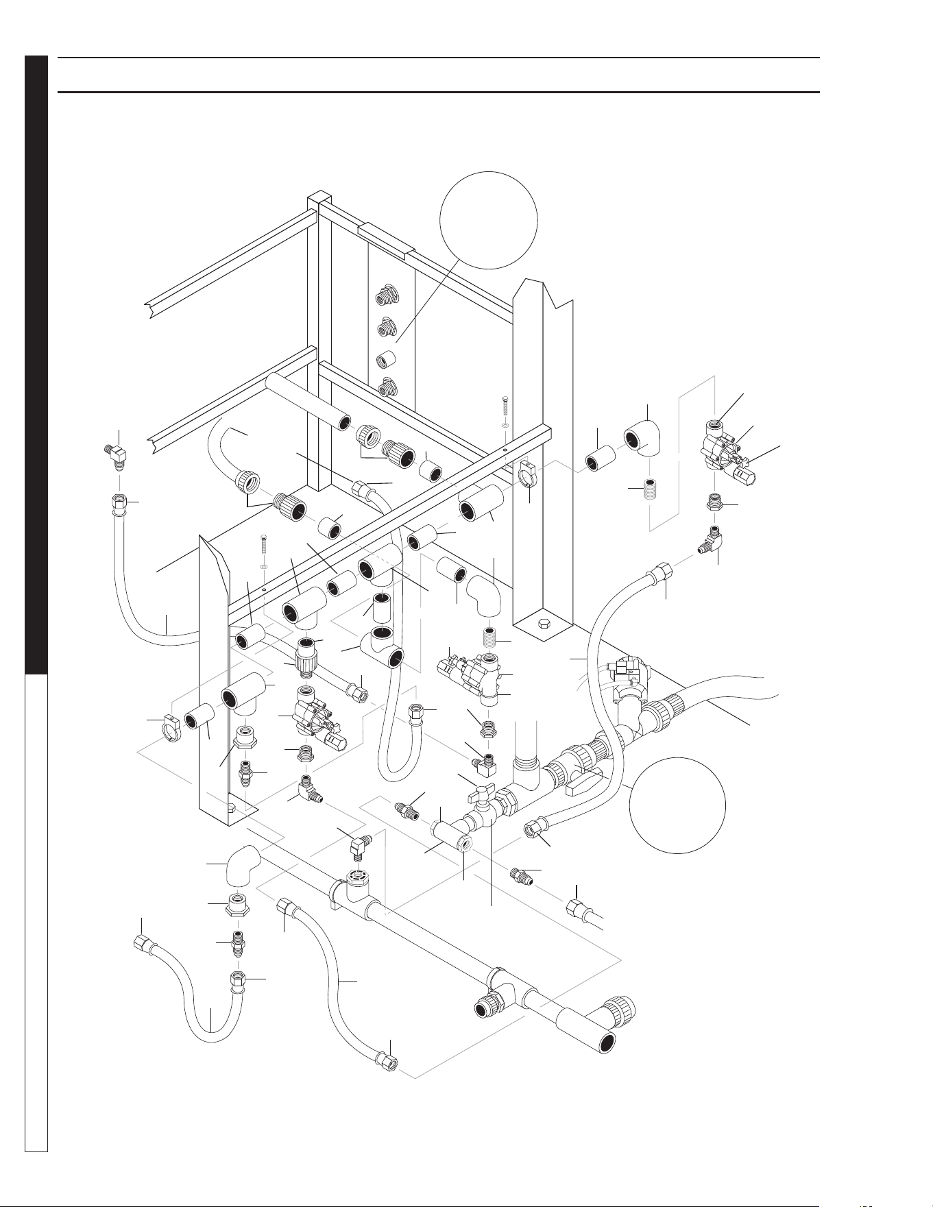
8.913-970.0 - L • WATERMAZE CLP 5024/7034
OPERATOR’S MANUAL WATER TREATMENT SYSTEM
64
CLP-7034 MANIFOLD PLUMBING EXPLODED VIEW
89139700-23
17
To Transfer
Pump
15
13
1
13
15
1
To Water
Panel
To
Vertical
Storage
Tank #1
For Detail
See CLP-
7034 Water
Panel
Breakdown
13
6
13
6
13
2
1
6
13
13
16
6
10
8
7
13
14
4
1
3
7
6
4
1
7
9
3
3
4
1
5
4
7
2
1
1
2
1
To
Surge
Tank
For
Detail See
CLP-7034
Tank Drain/
Oil Skimmer
Illus.
8
1
10
To
Main Tank
Blowdown
Port
13
12
11
8
10
3
2
1
13
14
6
12
11
SV3
Valve 9
Valve 17
SV4
Valve 14

8.913-970.0 - L • WATERMAZE CLP 5024/7034
65
WATER TREATMENT SYSTEM
OPERATOR’S MANUAL
CLP-7034 MANIFOLD EXPLODED VIEW PLUMBING PARTS LIST
PART ITEM NO. DESCRIPTION QTY
1 9.802-152.0 Swivel, 3/4" SAE Fem,
Push-On 10
2 9.802-261.0 Hose, 3/4" Push-On 12 ft.
3 9.802-132.0 Elbow, 3/4" JIC x 1/2", 90° 4
4 8.706-899.0 Nipple, 3/4" JIC x 3/4" Pipe 4
5 8.706-373.0 Elbow, 1" S x S, PVC 80, 90° 1
6 8.706-430.0 Tee, 1" S x S, PVC 80 6
7 8.706-447.0 Adapter, 1", 3/4" S x FIPT,
PVC 80 4
8 8.716-697.0 Solenoid, Water Maze
PVC 24V 3
PART ITEM NO. DESCRIPTION QTY
9 8.707-359.0 Valve, 1" S 80 PVC S x S
Molded in Place 1
10 8.706-928.0 Bushing, 1" x 1/2" Black Poly 3
11 8.706-439.0 Nipple, 1", Close 2
12 8.706-378.0 Elbow, 1" S x FIPT, 90° 2
13 8.706-366.0 Pipe, 1" PVC 80 2 ft.
14 8.706-422.0 Hanger, 1-1/4", Pipe Clip #40 2
15 8.706-597.0 Union, 1", S x S 2
16 8.706-409.0 Adapter, 1" MT x S 1
17 9.803-557.0 Elbow, 3/4" SAE x 3/4" 1
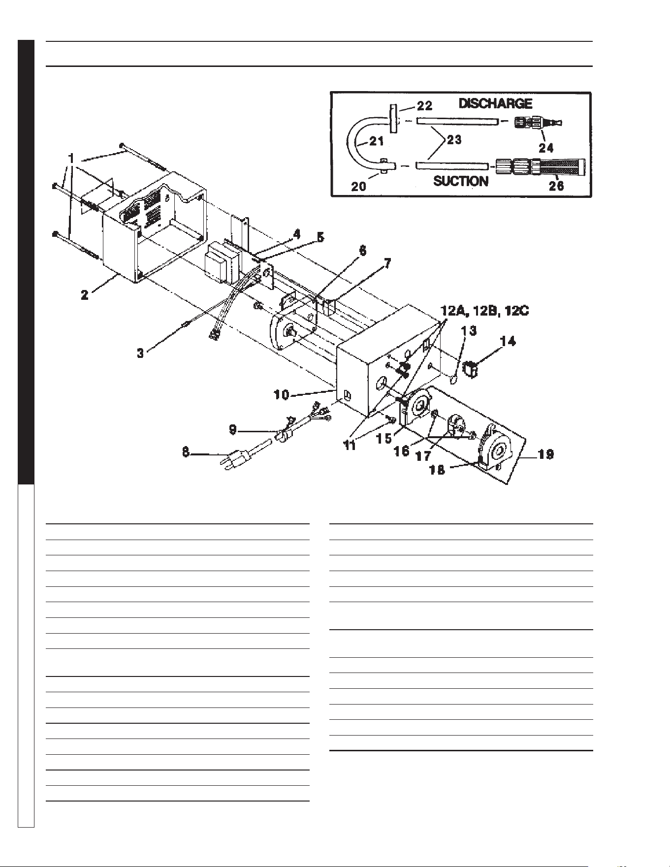
8.913-970.0 - L • WATERMAZE CLP 5024/7034
OPERATOR’S MANUAL WATER TREATMENT SYSTEM
66
METERING PUMP EXPLODED VIEW & PARTS LIST
8.715-378.0 • VSP20
ITEM PART # DESCRIPTION QTY
1 66-817995 Screw 4
2 66-818046 Rear Assembly 1
3 66-818071 Lead Assembly 1
4 66-U0818305 PCB 1
5 66-818463 Fuse 1
6 8.716-982.0 Gearmotor Kit 1
7 66-818315 Circuit Support 1
8 66-818320 Power Cord 1
9 66-L9900700-000
Strain Relief 1
10 66-818045 Front Housing 1
11 66-817888 Shoulder Screw 2
12A 66-818666 Motor Screw 2
12B 66-32946 Motor Nut 2
12C 66-811297 Lockwasher 2
13 66-818083 Hole Plug 1
14 66-817923 Switch 1
15 8.716-975.0 Pump Cover 1
ITEM PART # DESCRIPTION QTY
16 8.716-973.0 Bearing 2
17 8.716-977.0 Spider Assembly 1
18 8.716-976.0 Pump Housing 1
19 8.716-985.0 Pump Head Kit 1
20 8.716-974.0 Collar VSP-202
21 8.711-735.0 Tube, Tygon 1
(used for caustic solutions)
8.711-736.0 Tube, Norprene, Feeder
Suction Sleeve - Standard 1
22 8.716-978.0 Hose Clamps 2
23 8.716-984.0 Tubing, 1/4" OD, 11/64" ID 1
24 8.716-986.0 I.P.F. 1
25 8.716-987.0 ▲ Lube Pad Kit 1
26 8.739-484.0 Strainer 1
Fig. 15 8.716-979.0 Items 20, 21, 22, 24, 26
▲ Not Shown
Figure 15. - #66-817976
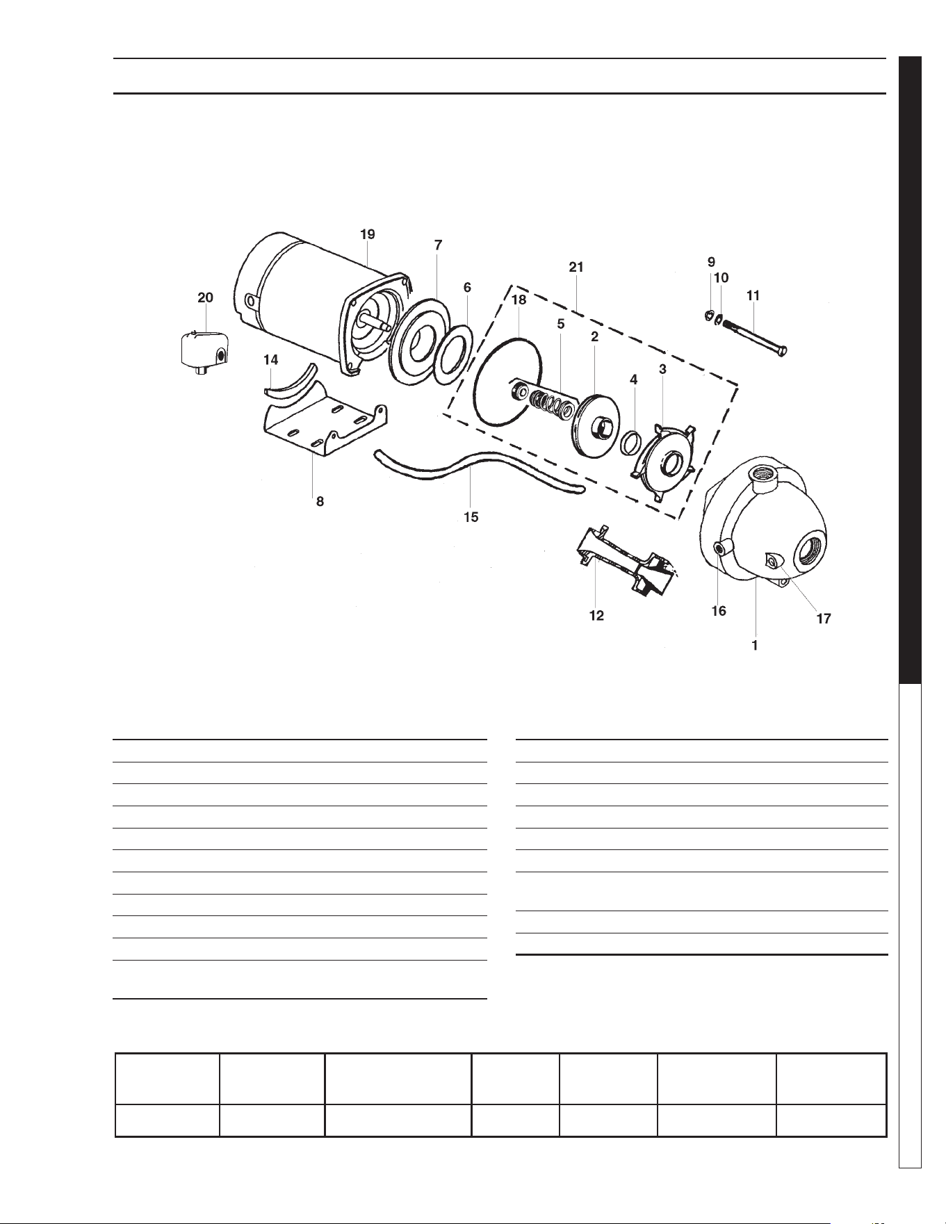
8.913-970.0 - L • WATERMAZE CLP 5024/7034
67
WATER TREATMENT SYSTEM
OPERATOR’S MANUAL
TRANSFER PUMP EXPLODED VIEW & PARTS LIST
#8.715-382.0 • 1/2 HP • 230 • 1PH (CLP-5024A)
ITEM PART NO. DESCRIPTION QTY
1 NA Case Assembly 1
2 NA Impeller 1/2 HP #2794 4-60D 1
3 NA Diffuser 1
4 NA Wear Ring 1
5 NA Mechanical Seal 1
6 NA Disk 1
7 NA Seal Plate 6-1/2" D 1
8 NA Base w/ #14 Rbr. Protector 1
9 NA Hex Nut 3/8" - 16 PL. 4
10 NA Lock Washer 3/8" Reg. 4
11 NA Hex Capscrew
3/8"-16 x 2-3/4" PL. 4
ITEM PART NO. DESCRIPTION QTY
12 NA Noz./Venturi f/5CY 1
14 NA Base Protector 1
15 NA Tube 1/4" x 14-1/2"
Poly-Black 1
16 NA Barb Fitting 90 Degree Elbow 1
17 NA Plug 1/4" Galv. 1
18 NA O-Ring 6" x 3/8" x 3/16" 1
19 NA Motor 1/2 HP 3450 RPM
56Z Frame 1
20 8.716-154.0 Pressure Switch Set 20/40 1
21 8.716-795.0 5 Cy. Impeller Repair Kit 1
MODEL NO. PART NO.
SIZE
INLET OUTLET
RUNNING
AMPS
VOLTS
MAX. WATER
TEMP.
PHASE
5CY 8.715-382.0 1-1/4" 1" 9.6 / 4.8 115 / 230 120°F/50°C 1
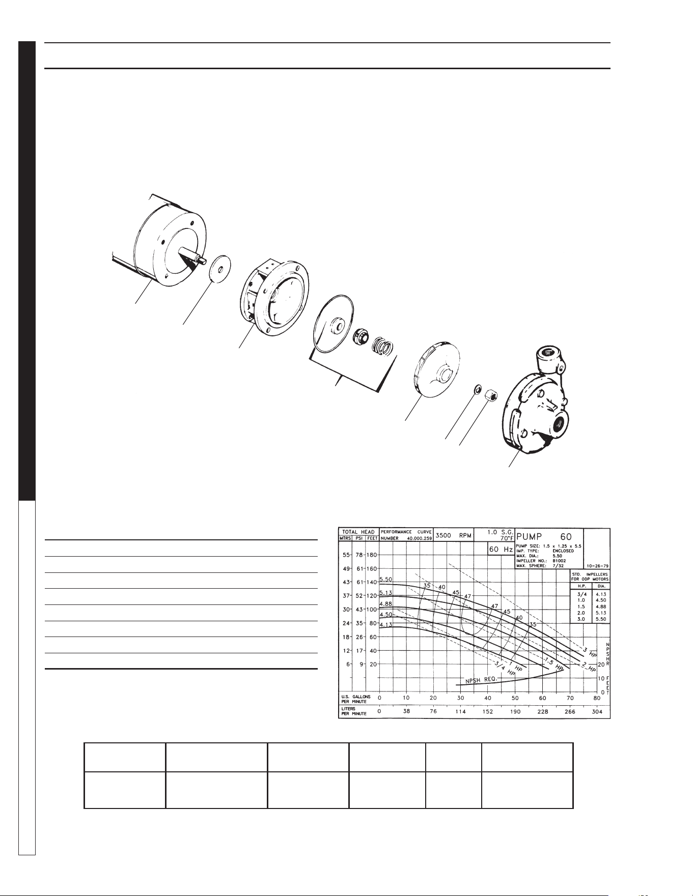
8.913-970.0 - L • WATERMAZE CLP 5024/7034
OPERATOR’S MANUAL WATER TREATMENT SYSTEM
68
FILTER & TRANSFER PUMP EXPLODED VIEW & PARTS LIST
#8.715-400.0 • 1/2 HP • 230/460V • 3 PH (CLP-5024B, C)
1
2
3
4
5
6
7
8
MODEL NO.
SIZE
INLET OUTLET AMPS VOLTS PHASE MAXGPM, PSI
60 1-1/2" 1-1/4" 6.8, 3.4 230/460 3
See Chart
Above
ITEM PART NO. DESCRIPTION QTY
1 8.718-520.0 Washer 1
2 88-132000200 Base 1
3 8.718-523.0 Seal 1
4 88-137.000.001 5-5" 3 phase Impeller 1
5 88-104000168 Washer 1
6 8.718-521.0 Nut 1
7 88-130000181 Head 1
8 88-1130000360 Motor, 1-1/2 HP 230/460V 3 PH 1
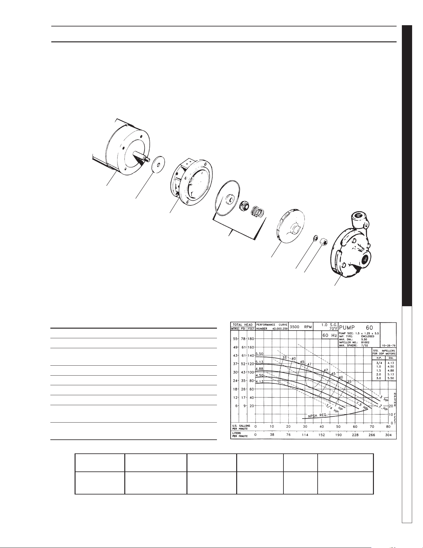
8.913-970.0 - L • WATERMAZE CLP 5024/7034
69
WATER TREATMENT SYSTEM
OPERATOR’S MANUAL
FILTER & TRANSFER PUMP EXPLODED VIEW PARTS LIST
#8.715-402.0 • 2 HP • 230V • 1PH (CLP-7034A)
#8.715-404.0 • 2 HP • 230/460V • 3PH (CLP-7034B,C)
ITEM PART NO. DESCRIPTION QTY
1 8.718-520.0 Washer 1
2 88-132000200 Base 1
3 8.718-524.0 Seal, 1 Phase 1
8.718-523.0 Seal, 3 Phase 1
4 8.718-534.0 5-5" Impeller, 2 HP 1
5 88-104000168 Washer 1
6 8.718-521.0 Nut 1
7 88-130000170 Head 1
8 88-113000348 Motor, 2 HP 230V 1 PH
(CLP-7034A) 1
88-113000349 Motor, 2 HP 230V/460V
3 PH (CLP-7034B, C) 1
1
2
3
4
5
6
7
8
MODEL NO.
SIZE
INLET OUTLET AMPS VOLTS PHASE MAXGPM, PSI
60 1-1/2" 1-1/4" 6.8, 3.4 230/460 3
See Chart
Above
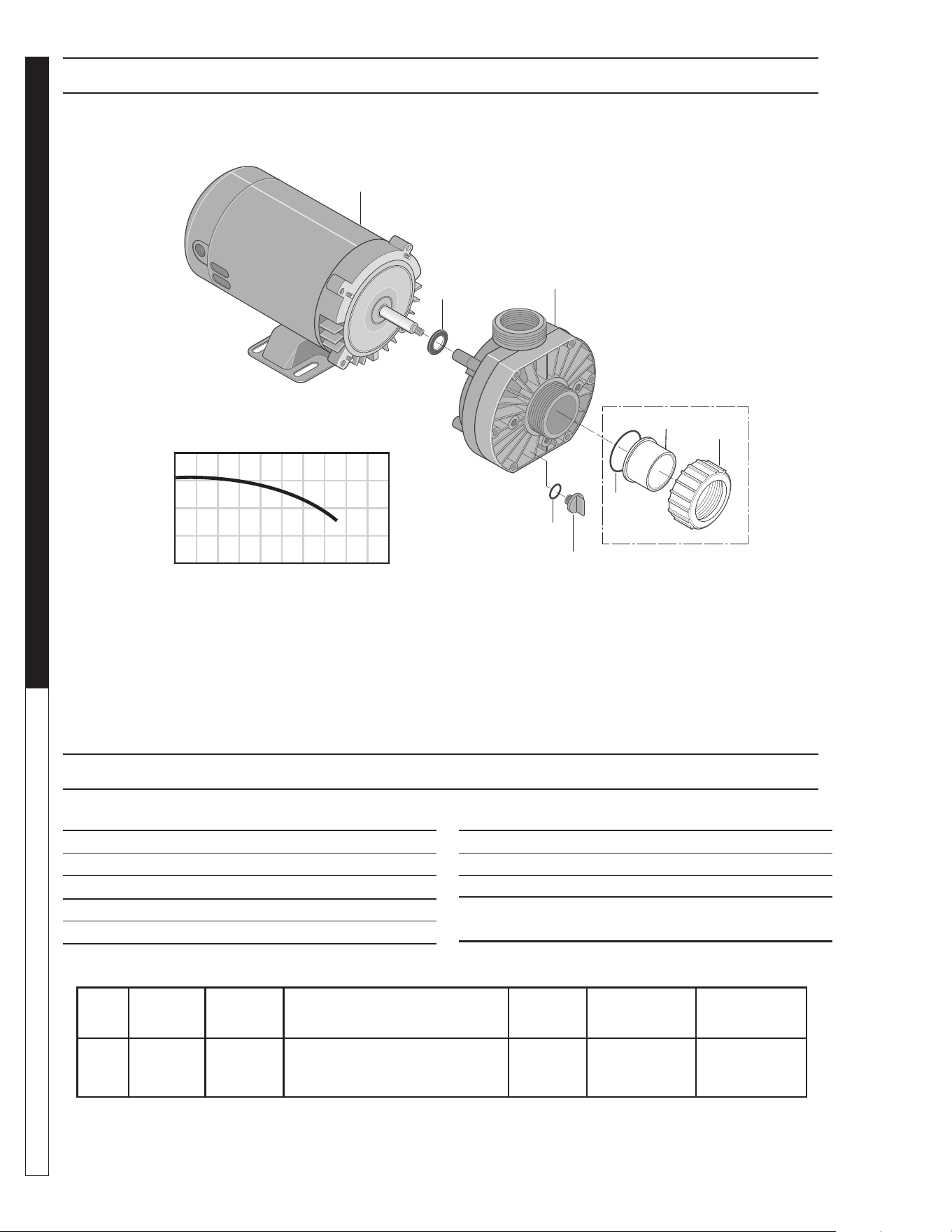
8.913-970.0 - L • WATERMAZE CLP 5024/7034
OPERATOR’S MANUAL WATER TREATMENT SYSTEM
70
OZONE PUMP EXPLODED VIEW
ITEM PART NO. DESCRIPTION QTY
1 8.726-026.0 Motor, 3/4 HP, 230V 1
2 NA Slinger 1
3 8.726-024.0 Pump, 3/4 HP, Wet End 1
4 NA Drain Plug 1
5 NA O-Ring, Drain Plug 1
HP Volts Phase
Size
Inlet Outlet
Running
Amps
Max.
Pressure
Max.
Water Temp.
3/4 230V 1 1-1/2" FPT/ 1-1/2"FPT/
1-1/2" MBT 1-1/2" MBT
5.7 40 PSI 104°F/40°
ITEM PART NO. DESCRIPTION QTY
6 NA O-Ring 1
7 NA Adapter, Union 1-1/2” Slip 1
8 NA Collar, Union 1
Kit:
6-8 8.750-270.0 Fitting, Compression, 1-1/2" Slip
Part # 8.917-760.0
OZONE PUMP EXPLODED VIEW PARTS LIST
40
20
0
20 40 60 80
U.S. GALLONS PER MINUTE
TOTAL HEAD IN FEET
1
2
3
4
5
6
7
8
Not Included
With Pump
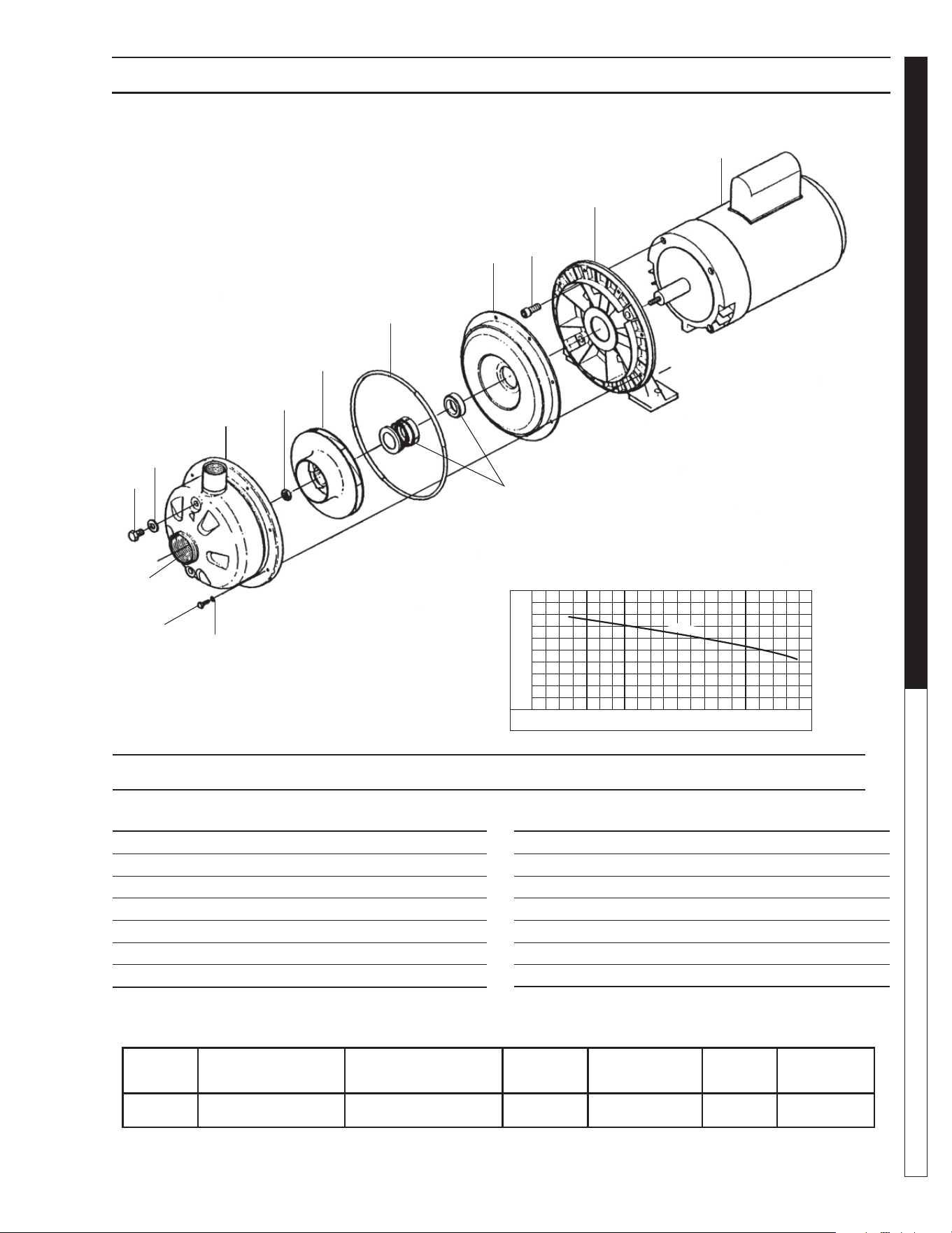
8.913-970.0 - L • WATERMAZE CLP 5024/7034
71
WATER TREATMENT SYSTEM
OPERATOR’S MANUAL
ITEM PART NO. DESCRIPTION QTY
1 NA Motor, 3/4 HP 1
2 NA Bracket, Aluminum 1
3 NA Bolt, 304L SS 4
4 NA Casing Cover, 304L SS 1
5 8.750-017.0 Mechanical Seal 1
6 8.718-513.0 O-Ring, Viton 1
7 8.753-424.0 Impeller, 4.12", 304L SS 1
8.723-219.0 • 230/460V • 3 PH • 3/4 HP
(CLP-5024B, C; CLP-7034B, C)
BRAND MODEL NO.
SIZE
INLET OUTLET AMPS VOLTS PHASE GPM / PSI
Ebara ACDU 70 1-1/4" 1" 3.2-3/1.5 208-230/460 3 See Chart
1
8
3
4
5
6
7
2
OZONE PUMP EXPLODED VIEW
9
11
12
13
10
14
0 10 20 30 40
90
80
70
60
50
40
30
20
FT
TOTAL HEAD
T.D.H
ITEM PART NO. DESCRIPTION QTY
8 NA Impeller Nut, 304L SS 1
9 NA Casing, 304L SS 1
10 NA Washer, Aluminum 2
11 NA Plug, 304L SS 2
12 NA Washer, 304L SS 8
13 NA Bolt, 304L SS 8
14 NA Casing Ring, Viton 1
OZONE PUMP EXPLODED VIEW PARTS LIST
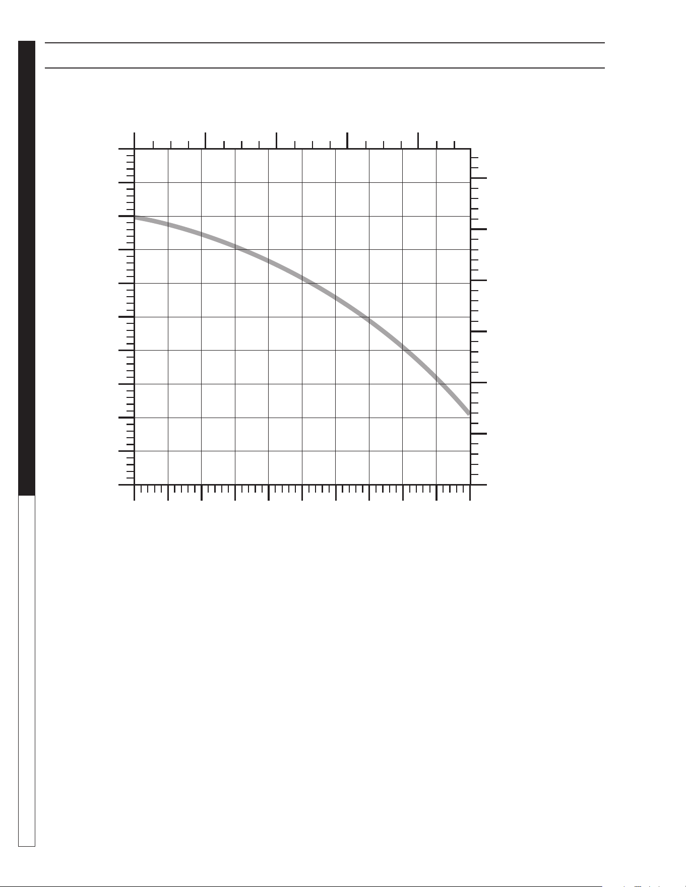
8.913-970.0 - L • WATERMAZE CLP 5024/7034
OPERATOR’S MANUAL WATER TREATMENT SYSTEM
72
SUBMERSIBLE SUMP PUMP SPECIFICATION
Flow - (Liters/Minute)
0 40 80 120 160
Head - (Feet)
Flow - (Gallons/Minute)
0
0
5
10
15
20
25
10 20 30 40 50
Head - (Meters)
0
1.25
2.50
3.75
5.00
6.25
7.50
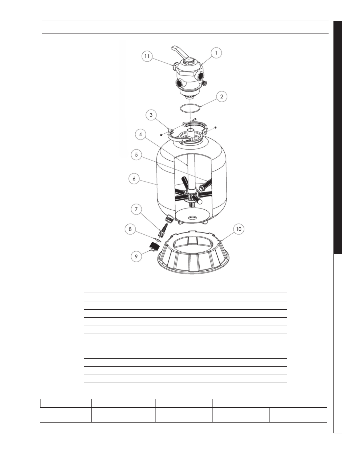
8.913-970.0 - L • WATERMAZE CLP 5024/7034
73
WATER TREATMENT SYSTEM
OPERATOR’S MANUAL
# 8.726-028.0 (CLP-5024)
ITEM PART NO. DESCRIPTION QTY
1 8.726-030.0 Multiport Valve, Top Mount 1
2 NA O-Ring, Valve Body 1
3 NA Clamp Assembly 1
4 NA Piping Assembly 1
5 NA Lateral 8
6 NA Filter Tank w/Drain 1
7 NA Drain Lateral 1
8 NA Gasket, Drain Cap 1
9 NA Drain Cap 1
10 NA Pedestal 1
11 NA Pressure Gauge 1
MULTI-MEDIA & CARBASORB FILTER EXPL. VIEW & PARTS LIST
Tank Diameter Max. Working Pressure Vert. Clearance Max. Water Temp Valve
24" 40 PSI 58" 95°F 6 Position
1-1/2" FPT/MBT
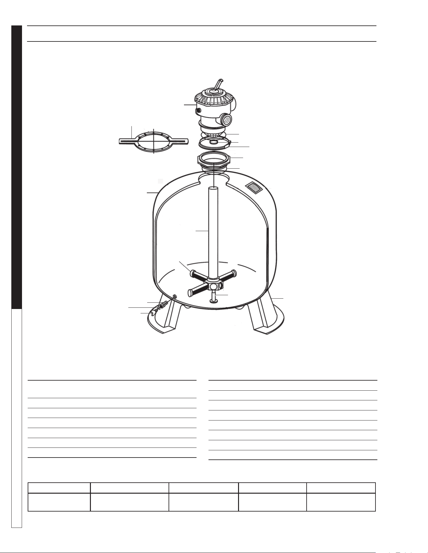
8.913-970.0 - L • WATERMAZE CLP 5024/7034
OPERATOR’S MANUAL WATER TREATMENT SYSTEM
74
CARBASORB FILTER EXPLODED VIEW & PARTS LIST
8.726-029.0 • TAGELUS 100D (CLP-7034)
ITEM PART NO. DESCRIPTION QTY
1 8.726-031.0 Valve, 6-pos., Top Mount
Tagelus, 2" Ports 1
2 NA O-Ring, Valve Flange 1
3 NA O-Ring, Standpipe 1
4 NA Clamp 8.35" Dia 1
5 NA Adapter 1
6 NA O-Ring, Adapter 1
7 NA Filter Tank 1
ITEM PART NO. DESCRIPTION QTY
8 NA Stabilizer, Center Pipe 1
9 NA Piping 1
10 NA Lateral 6
11 NA Pedestal 1
12 NA Drain 1
13 NA O-Ring, Drain 1
14 NA Drain Plug 1
15 NA Wrench 1
Tank Diameter Max. Working Pressure Vert. Clearance Max. Water Temp Valve
30-1/2" 50 PSI 65-1/2" 104°F Tagelus 6 Position
w/2" Ports
1
2
3
4
5
6
7
8
9
10
11
12
13
14
15
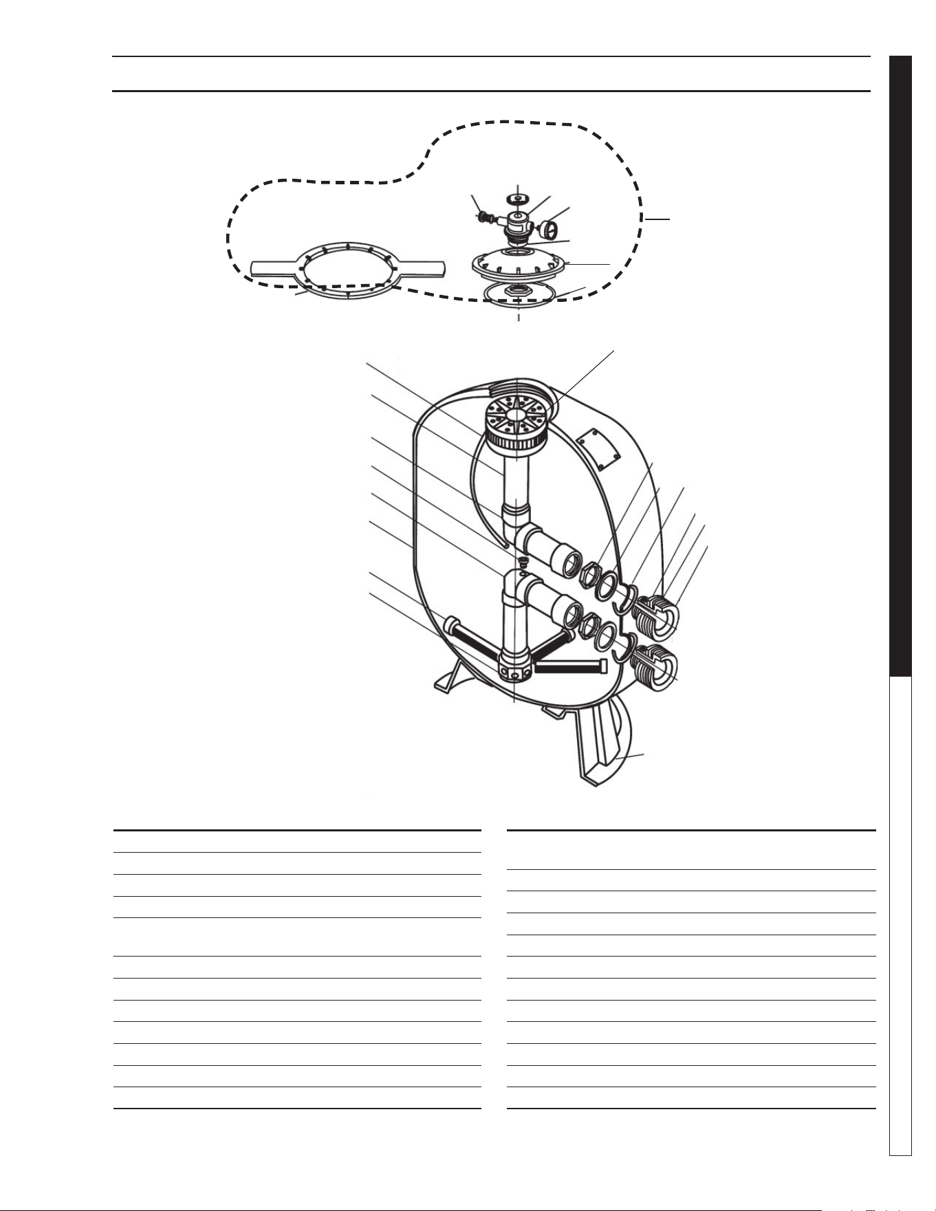
8.913-970.0 - L • WATERMAZE CLP 5024/7034
75
WATER TREATMENT SYSTEM
OPERATOR’S MANUAL
ITEM PART NO. DESCRIPTION QTY
1 NA Air Bleeder/Tee Assy 1
2 NA Adaptor, Brass Air Bleeder 1
3 8.750-046.0 Gauge, Back Mount Pressure 1
4 NA O-Ring, Air Bleeder Adaptor 1
5 NA Closure, 6" Buttress Thread
Black 1
6 8.750-047.0 O-Ring Closure 1
7 NA Strainer, Air Relief 1
8 NA Tube, Air Relief 1
9 NA Diffuser, Assembly 1
10 NA Piping, Assembly, Upper 1
11 NA Connector, Air Relief Tube 1
12 NA Piping Assy, Lower 1
MULTI-MEDIA FILTER EXPLODED VIEW & PARTS LIST
ITEM PART NO. DESCRIPTION QTY
13 NA Tank and Foot Assy,
6" Buttress Thread, Blk 1
14 8.750-048.0 Lateral, 12"L 8
15 NA Hub, Lateral 1
16 NA Locknut, 2" Internal 2
17 NA Spacer, 2" Internal 2
18 NA O-Ring, 2" Bulkhead 2
19 NA Spacer, 2" External 2
20 NA Gasket, 2" Bulkhead 2
21 NA Bulkhead, 2" 2
22 NA Wrench, 6" Closure 1
23 NA Foot, 24" Dia. 1
24 8.750-049.0 Kit Closure, 8.5" 1
1
3
5
7
9
2
4
6
8
10
11
13
15
17
19
12
14
16
18
20
21
22
23
#8.723-203.0 • TR140 (CLP-7034)
24
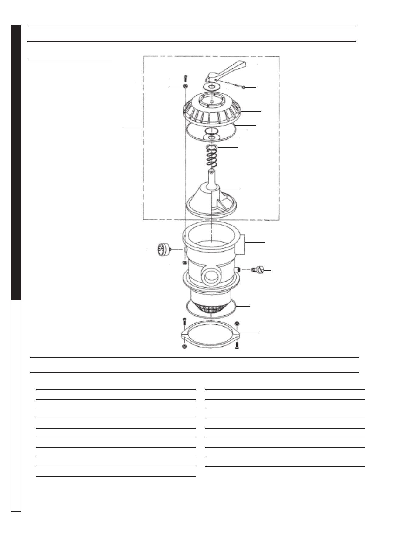
8.913-970.0 - L • WATERMAZE CLP 5024/7034
OPERATOR’S MANUAL WATER TREATMENT SYSTEM
76
6 POSITION VALVE
1-1/2" PORTS
8.726-030.0
ITEM PART NO. DESCRIPTION QTY
1 NA Handle 1
2 NA Washer, Plastic 2
3 NA Screw, Handle 1
4 NA Valve Top, Black 1
5 NA O-Ring Diverter Shaft 1
6 NA O-Ring 1
7 NA Spring 1
8 NA Diverter w/Gasket 1
9 NA Screw, #10-24 1
ITEM PART NO. DESCRIPTION QTY
10 NA Washer, 9/16, SS 6
11 NA Nut, #10-24 6
12 NA Valve Body w/Diff - Clamp Style 1
13 NA Air Bleeder w/ O-Ring 1
14 NA O-Ring 1
15 NA Clamp Assembly (See note) 1
16 NA Pressure Gauge 1
17 NA Valve Top Assy (items 1-8) 1
Note: Clamp halves, nuts and bolts sold only in Assembly
2
5
8
11
14
3
6
9
12
15
1
4
7
10
13
16
17
2
6 POSITION VALVE ASSEMBLY PARTS LIST
6 POSITION VALVE ASSEMBLY
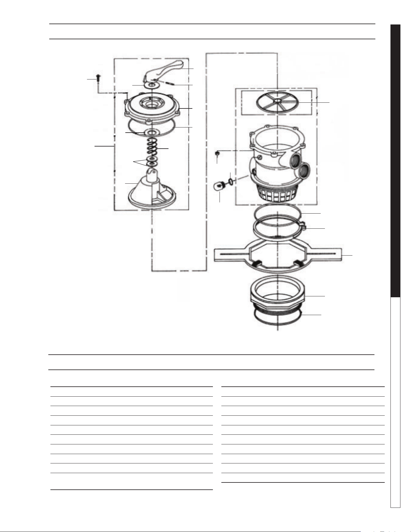
8.913-970.0 - L • WATERMAZE CLP 5024/7034
77
WATER TREATMENT SYSTEM
OPERATOR’S MANUAL
2" MULTI-PORT VALVE EXPLODED VIEW
ITEM PART NO. DESCRIPTION QTY
1 NA Top Valve Assy, 2" 1
2 NA Spider Gasket Diverter, 2" 1
3 NA Sight Glass 1
4 NA Gasket, Sight Glass 1
5 NA Nut, M6 S/S 6
6 NA Screw, M6 x 30mm S/S 6
7 NA O-Ring Valve, 2" 1
8 NA Band Assy, Valve, 2" 1
9 NA Wrench Adapter Flange 1
10 NA Adapter Flange, Buttress
Thread 2" 1
ITEM PART NO. DESCRIPTION QTY
11 NA O-Ring Adapter, 2" 1
12 NA Handle 1
13 NA Pin, Handle 1
14 NA Top Valve Cover, Black, 2" 1
15 8.749-868.0 O-Ring, Valve Top, 1-1/2" 1
16 NA Valve Spring 1
17 NA Valve Diffuser, 1-1/2" 1
18 NA O-Ring Stem 2
19 NA Washer, Valve Spring 1
20 NA Washer, Handle 1
2" MULTI-PORT VALVE EXPLODED VIEW PARTS LIST
8.726-031.0
Tagelus
3
1
2
4
5
6
7
8
9
11
12
13
14
15
16
17
18
10
19
20
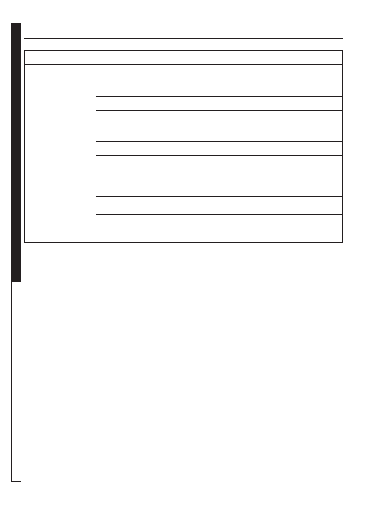
8.913-970.0 - L • WATERMAZE CLP 5024/7034
WATER TREATMENT SYSTEM
Troubleshooting Guide
78
TROUBLESHOOTING - CLP
PROBLEM POSSIBLE CAUSE SOLUTION
NO FLOW
OF WATER
INTO THE CLP
Control switch not in "ON" position
a. Mode switch turned to "HAND" position
b. Sump pump switch not turned to
"AUTO" position
Turn switch to "ON" position.
a. Turn to "AUTO" position.
b. Turn to "AUTO" position.
Power not turned "ON" at breaker box Turn "ON" power at breaker box.
Float on sump pump in down position Add water to pump.
Debris in sump impeller Unplug pump and remove from container.
Flow valve closed Open valve.
Dirt lodged in control valve Clean as needed.
Frozen water in lines or valves Thaw out with warm water.
WATER FLOWING
OVER CLP
Tank not level Level tank.
Water coming into the CLP faster than 5 -
30 gpm
Adjust fl ow control valve.
Discharge line plugged Remove obstruction.
Pump not wired in Wire in pump.
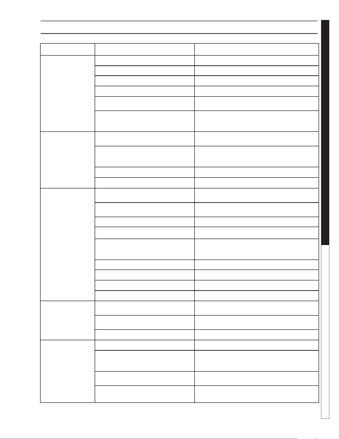
8.913-970.0 - L • WATERMAZE CLP 5024/7034
79
WATER TREATMENT SYSTEM
Troubleshooting Guide
TROUBLESHOOTING - PUMP
PROBLEM POSSIBLE CAUSE SOLUTION
PUMP DOES
NOT TURN
ON
Circuit breaker shut "OFF" Turn "ON" circuit breaker.
Accumulation of trash on fl oat Clean fl oat.
Float obstruction Check fl oat path and provide clearance.
Defective switch Check and replace.
Defective motor
Have pump serviced by authorized service cen-
ter.
Low line voltage
If voltage under recommended minimum, check
size of wiring from main switch on property. If
OK, contact power company.
PUMP WILL
NOT SHUT
OFF
Float obstruction
Check fl oat and fl oat rod path and provide clear-
ance.
Pump is air locked (Transfer Pump)
Shut power off for approximately 1 minute, then
restart. Repeat several times to clear air from
pump.
Liquid infl ow matches pump capacity Larger pump required.
Defective fl oat switch Disconnect switch, check with ohmmeter.
PUMP RUNS
BUT DOES
NOT DISCHARGE
LIQUID
Check valve installed backwards
(Transfer Pump)
Check fl ow indicating arrow on check valve body
to insure it is installed properly.
Check valve stuck or plugged
(Transfer Pump)
Remove check valve and inspect for proper
operation.
Lift too high for pump Check rating table.
Inlet to impeller plugged Pull pump and clean.
Low line voltage
If voltage under recommended minimum, check
size of wiring from main switch on property. If
OK, contact power company.
Clogged impeller Remove housing, unclog.
Faulty motor protector Replace pump.
Very low head or lift Increase head or lift.
Sump pit too small Increase size of pit.
PUMP DOES
NOT DELIVER
RATED
CAPACTIY
Low voltage, speed to slow
Check for proper supply voltage to make certain
it corresponds to nameplate voltage.
Impeller or discharge pipe is clogged.
Pull pump and clean. Check pipe for scale or
corrosion.
Impeller wear due to abrasives Replace worn impeller.
PUMP
CYCLES
CONTINUALLY
Check valve leaking (Transfer Pump) Inspect check valve for correct operation.
Low line voltage
If voltage under recommended minimum, check
size of wiring from main switch on property. If
OK, contract power company.
Worn or defective pump parts or
plugged impeller
Replace worn parts or entire pump.
Clean parts if required.
Pump air locked
Turn pump "ON" and "OFF" several times.
Fill hose manually with water.
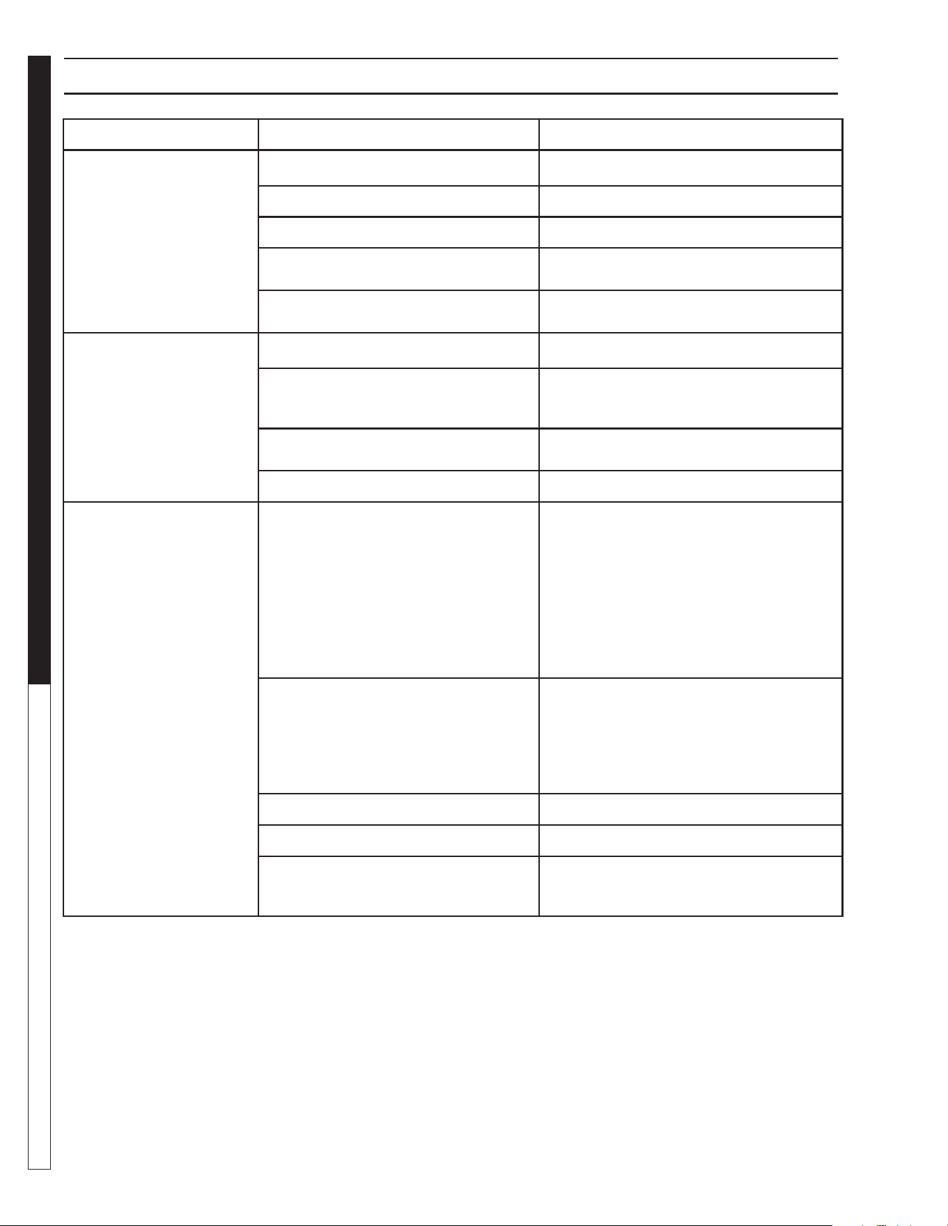
8.913-970.0 - L • WATERMAZE CLP 5024/7034
WATER TREATMENT SYSTEM
Troubleshooting Guide
80
TROUBLESHOOTING - PUMP MOTOR
PROBLEM POSSIBLE CAUSE SOLUTION
MOTOR WILL
NOT RUN
Disconnect switch is "OFF" Be sure switch is on.
Breaker is tripped Reset breaker.
Starting switch is defective Replace starting switch.
Wires at motor are loose, disconnected
or wired incorrectly
Refer to instructions on wiring.
Check and tighten all wiring.
Pressure switch contacts are dirty
(Transfer Pump)
Clean by sliding piece of plain paper
(or crocus cloth) between contacts.
MOTOR RUNS
HOT AND OVERLOAD
KICKS OFF
Motor is wired incorrectly Refer to instructions on wiring.
Voltage is too low Check with power company. Install heavier
wiring if wire size is too small. See wiring
instructions.
Pump cycles too frequently
See section below on too frequently
cycling.
Defective fl oat switch Disconnect switch, check with ohmmeter.
MOTOR RUNS
BUT NO WATER
IS DELIVERED
Pump in a new installation did not pick
up prime through:
a. Improper priming
a. Re-prime (3 or 4 times may be needed)
by stopping and starting motor several
times.
b. Air leaks
b. Check all connections on suction line.
c. Leaking check valve (Transfer Pump) c. Clean and/or replace check valve.
Pump has lost its prime through:
a. Air leaks a. Check all connections on suction line,
air volume control, jet and shaft seal.
b. Water level below suction of pump b. Lower suction line into water and
re-prime.
Jet or impeller is plugged Clean jet or impeller, see Maintenance.
Check valve is stuck in closed position Replace check valve.
Pipes are frozen
Thaw pipes. Bury pipes below frost line.
Heat pipes below frost line. Heat pit or
pump house.
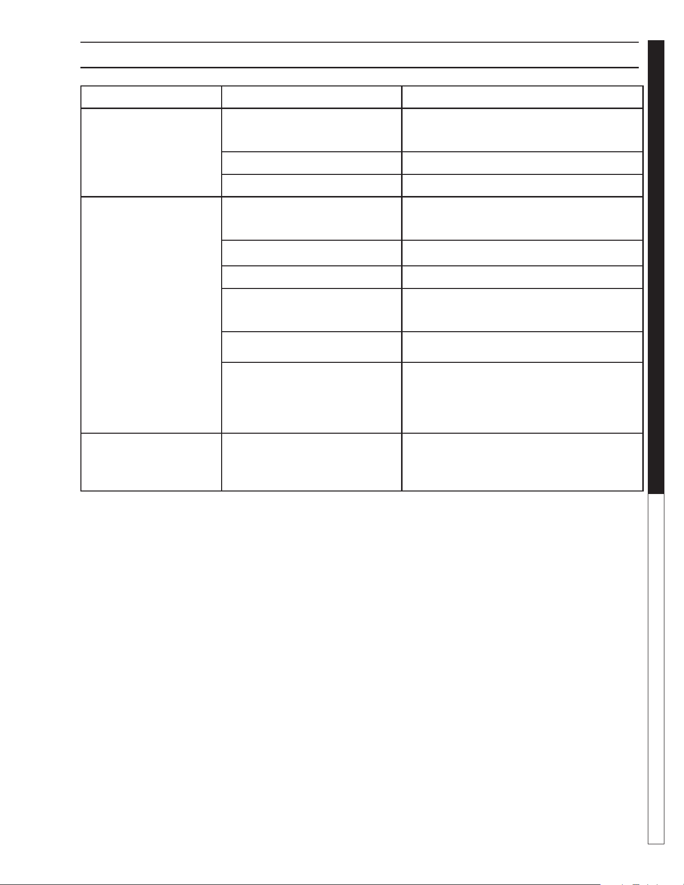
8.913-970.0 - L • WATERMAZE CLP 5024/7034
81
WATER TREATMENT SYSTEM
Troubleshooting Guide
TROUBLESHOOTING - FILTER
PROBLEM POSSIBLE CAUSE SOLUTION
RUNNING
AT HIGH
PRESSURES
Multi-Media or Carbon Filter
coated with normal accumulation
of dirt, etc
Backwash is needed.
Check backwash fl ow rates.
Cartridge fi lter plugged Cleaning is needed.
Obstruction in line to tank #1 Remove obstruction.
DROP OFF
OF DISCHARGE
FLOW
Multi-Media or Carbasorb Filter
coated with normal accumulation
of dirt, etc
Backwash is needed.
Check backwash fl ow rates.
Valve #1 closed Open valve.
Cartridge fi lter clogged Clean.
Pump impeller vanes clogged
Cleaning with a stiff wire through the pump inlet
opening will usually work. Alternate would be to
disassemble and clean.
Air leak on suction side of pump
Check cover gasket, hand knobs, hose,
clamps, etc. Replace or tighten as necessary.
Electric motor running less than
rated RPM (underspeed)
Consult pump and motor troubleshooting guide.
NOTE: Most motor problems are due to:
1. Undersized or improper wiring.
2. Power cutbacks or a combination of both.
SHORT
CYCLES
Multi-Media or Carbasorb Filter
loaded to capacity with dirt, etc
Backwash.
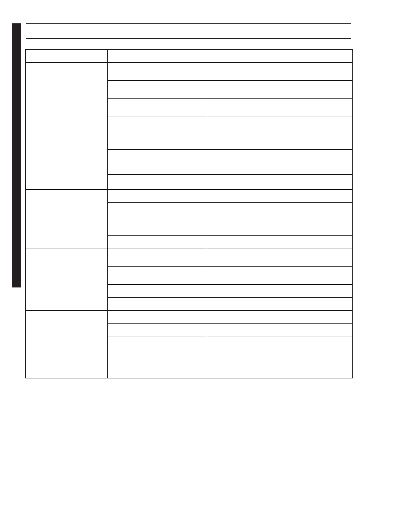
8.913-970.0 - L • WATERMAZE CLP 5024/7034
WATER TREATMENT SYSTEM
Troubleshooting Guide
82
TROUBLESHOOTING - WATER SOLENOID
PROBLEM POSSIBLE CAUSE SOLUTION
VALVE LEAKS
WHEN "OFF"
Dirt or debris on
diaphragm seat
Clean diaphragm seat.
Solenoid not fully closed after
manual operation
Turn solenoid clockwise to fully seated position.
Solenoid O-ring damaged or
twisted
Turn off water, inspect O-ring. Reseat if twisted,
replace if damaged.
Diaphragm damaged
Turn off water, remove bonnet screws and
inspect diaphragm for nicks or damage. NOTE:
Diaphragm has one blood hole molded into it.
Replace, if necessary, with diaphragm kit.
Dirt interfering with solenoid
operation
Turn off water, remove solenoid and fl ush
seating surface in bonnet and at bottom
of solenoid with water.
Solenoid damaged Turn off water supply and replace solenoid.
WATER WON'T
SHUT OFF
Valve in manual "ON" position Turn solenoid clockwise to "OFF" position.
Diaphragm bleed hole blocked
Use Manual Flush Mode. Turn water supply
"OFF" and immediately back "ON" to clear
blockage. If still blocked, turn off water
and inspect diaphragm looking for blockage.
Damaged solenoid Turn off water supply and replace solenoid.
LOW OR INADEQUATE
FLOW CONDITION
Water running elsewhere using
up pressure
Turn off water that is running elsewhere.
Too many solenoids running at
once
Adjust so water is running to only one solenoid.
Gate valve not fully open Open gate valve fully.
Pipeline blockage Clear pipeline.
VALVE WON'T
TURN ON
ELECTRICALLY
No power to solenoid Make sure solenoid has power.
Low voltage Make sure there is 24 volts.
No water pressure
Make sure water pressure is available to valve.
Turn off water, without cutting wires, unscrew and
swap solenoids between valves. Turn on water
and test again. If problem stems from the sole-
noid, replace solenoid.

8.913-970.0 - L • WATERMAZE CLP 5024/7034
83
WATER TREATMENT SYSTEM
Troubleshooting Guide
TROUBLESHOOTING - WATER SEALS
PROBLEM POSSIBLE CAUSE SOLUTION
CRACKED OR BROKEN
STATIONARY SEAT
(CERAMIC)
Seal ran dry and heated up.
When liquid reached seal faces
it was cooler, causing thermal
cracks
Check to insure seal chamber is full of liquid
before starting pump. On high temperature
application insure proper fl ushing at seal faces.
CARBON WASHER
SCORED AND GROOVED
Dirty system Have system cleaned and fl ushed. Consider
use of Tungsten Carbide or Silicon Carbide
Rings.
CARBON WASHER
WORN UNEVENLY
Seal improperly installed Check installation instructions for
proper assembly.
FLEXIBLE DIAPHRAGM
BROKEN
Coupling misalignment Realign pump and motor.
SHORT SEAL LIFE IN
TREATED SYSTEMS
Treatment level and temperature
higher than anticipated
Use Viton Elastomers, High Temperature
Carbon, Ni Resist Tungsten Carbide or Silicon
Carbide Seat.
BUNA DIAPHRAGM
HARD AND BRITTLE.
RAPID CARBON WEAR.
Air leak on suction side of pump Check cover gasket, hand knobs, hose,
clamps, etc. Replace or tighten as necessary.
DIAPHRAGM SOFT AND
STICKY; APPEARS TO
BE DISSOLVING.
Bellows not compatible with
material being pumped
Consult factory for recommendation advising
of pumpage and temperature.

8.913-970.0 - L • WATERMAZE CLP 5024/7034
OPERATOR’S MANUAL WATER TREATMENT SYSTEM
84
CONSUMABLE PARTS
PART NO. DESCRIPTION
Wash-Water Consumable Parts
8.716-600.0 Ozone Generator Replacement Lamp (110V & 220V)
8.718-920.0 .45 x .55 mm Sand (Std. bag size - 50 lbs.)
8.718-921.0 1/4" x 1/8" Gravel (Std. bag size - 50 lbs.)
8.718-922.0 .60 x .80 mm #1 Anthracite (Std. bag size - 50 lbs.)
8.718-923.0 Garnet, 30 x 40 (Std. bag size - 100 lbs.)
8.718-924.0 Garnet, 8 x 12 (Std bag size - 100 lbs.)
8.718-933.0 Activated Carbon (50 lb. bag)
8.720-008.0 5-Way Test Strips
8.720-010.0 pH Test Strips
2-226V88475 O-Ring, Viton, 1.5", Unions
2-332V88475 O-Ring, Viton, 2", Unions
8.719-191.0 Bags
8.707-355.0 Check Valve, Ozone
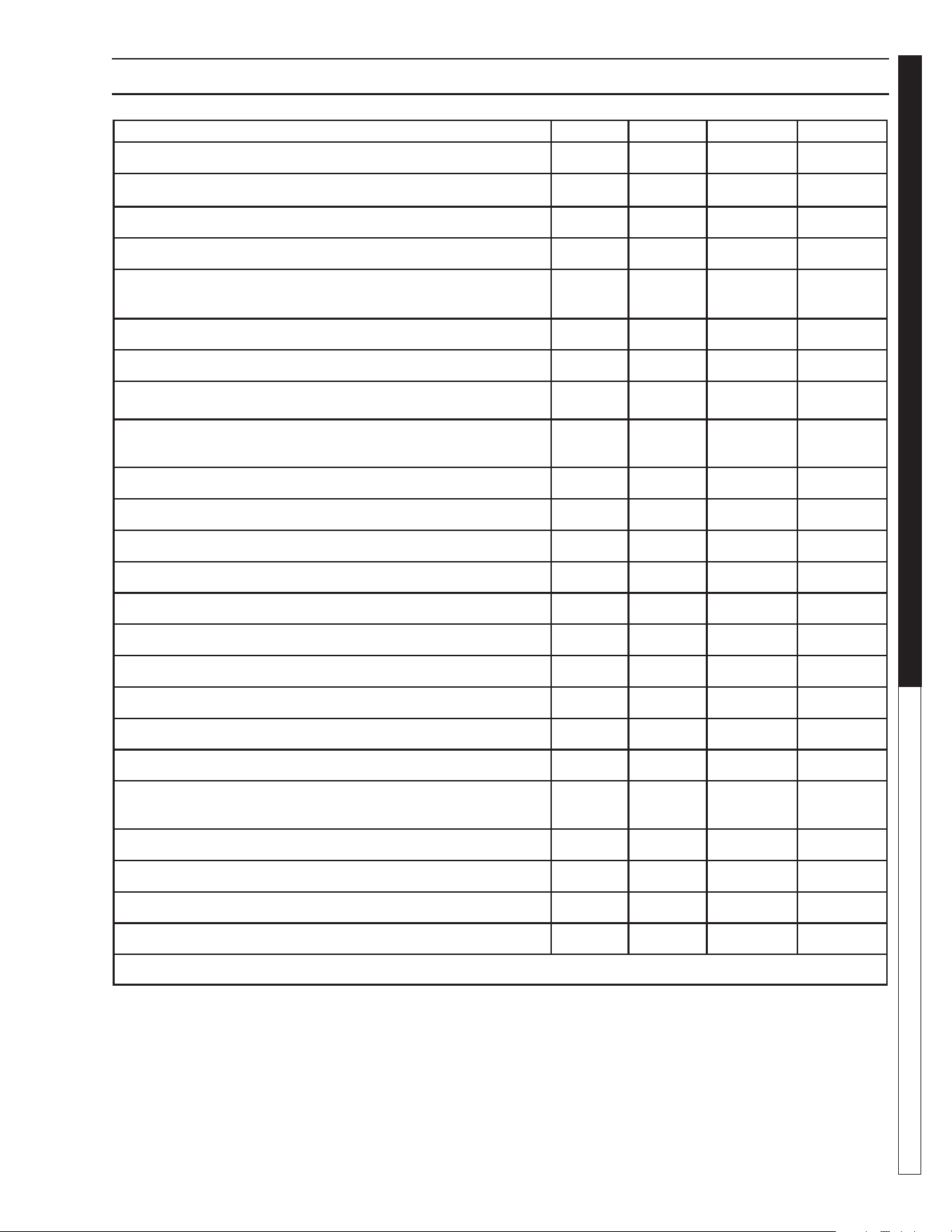
8.913-970.0 - L • WATERMAZE CLP 5024/7034
85
WATER TREATMENT SYSTEM
Maintenance Guide
CLP-7034 MAINTENANCE SCHEDULE
DAILY WEEKLY MONTHLY BI-YEARLY
Check pits for water level (Overfl ow/dry).
X
Check for voltage to unit and that control panel switches are on.
X
Check all plumbing for leaks.
X
Check inlet fl ow meter for proper fl ow. Clean meter if needed.
X
Check that inlet and discharge manifold hoses and valves are
in proper position.
X
Check fi lter fl ow meter for proper fl ow. Clean meter if needed.
X
Check ozone generator panel lights for proper reading.
X
Check burlap bag under cone bottom for fullness*.
X
Check water chemistry and make adjustments/recalibrate
controller.
X
Check for proper air, 60-100 PSI
X
Check level of oil in collection tank.
X
Check adjustment on oil skimmer for proper level.
X
Clean and test probes.*
X
Suction pits of sludge and debris.*
X
Check and clean sump pump of dirt and debris.*
X
Clean fl oats in sump if accumulating dirt or grease. *
X
Check fl oat wires for cuts or frays.
X
Check and clean chemical injectors.
X
Check tubing on ORP/ph controller for splits or cracking.
X
Check standard cubic feet per hour (SCFM) on ozone
generator.
X
Clean circular tube in tank.
X
Clean fl oats for tank #1 and #2.
X
Test carbon*.
X
Check surge tank pressure.
X
* NOTE: This is a guide. Depending on your wash load these items may have to be done more or less often.

8.913-970.0 - L • WATERMAZE CLP 5024/7034
WATER TREATMENT SYSTEM
WARRANTY
LIMITED NEW PRODUCT WARRANTY
WASH WATER / WATER TREATMENT SYSTEMS
WHAT THIS WARRANTY COVERS
All
WATER MAZE
water treatment systems are warranted by to the original purchaser to be free from defects in materials
and workmanship under normal use, for the periods specified below. This Limited Warranty, subject to the exclusions shown
below, is calculated from the date of the original purchase, and applies to the original components only. Any parts replaced
under this warranty will assume the remainder of the part’s warranty period. A 60 day grace period will be given for installa-
tion.
ONE YEAR PARTS AND 30 DAY LABOR WARRANTY:
All components excluding normal wear items as described below.
WARRANTY PROVIDED BY OTHER MANUFACTURERS:
Motors, which are warranted by their respective manufacturers, are serviced through these manufacturers’ local authorized
service centers.
WATER MAZE
cannot provide warranty on these items.
WHAT THIS WARRANTY DOES NOT COVER
This warranty does not cover the following items:
1. Normal wear items, such as seals, filters, gaskets, O-rings, packings, pistons, brushes, filtering media, ozone
bulbs, sensors, UV scanners, oil-skimmer belt, impedance sensor. Minor leaks covered first time on original start-
up only.
2. Damage or malfunctions resulting from accidents, abuse, modifications, alterations, incorrect installation, improper
servicing, failure to follow
manufacturer’s maintenance instructions, or use of the equipment beyond its stated
usage specifications as contained in the operator’s manual.
3. Damage due to freezing, sludge build-up, chemical deterioration (oxidation, chloride or fluoride corrosion), and
rust.
4. Damage to components from fluctuations in electrical or water supply.
5. Normal maintenance service, including adjustments.
6. Transportation to service center, field labor charges, or freight damage.
7. Consumables and water quality.
WHAT YOU MUST DO TO OBTAIN WARRANTY SERVICE
While not required for warranty service, we request that you register your
WATER MAZE
Product by returning the com-
pleted registration card. In order to obtain warranty service on items warranted by
WATER MAZE
, you must return the
product to your Authorized
WATER MAZE
Dealer, freight prepaid, with proof of purchase, within the applicable warranty
period. If the product is permanently installed, you must notify your Authorized
WATER MAZE
Dealer of the defect. Your
Authorized
WATER MAZE
Dealer will file a claim with
WATER MAZE
, who must subsequently verify the defect. In most
cases, the part must be returned to
WATER MAZE
freight prepaid with the claim. For warranty service on components
warranted by other manufacturer’s, your Authorized
WATER MAZE
Dealer can help you obtain warranty service through
these manufacturers’ local authorized service centers.
LIMITATION OF LIABILITY
WATER MAZE’S
liability for special, incidental, or consequential damages is expressly disclaimed. In no event shall
WATER MAZE’S
liability exceed the purchase price of the product in question.
WATER MAZE
makes every effort to ensure
that all illustrations and specifications are correct, however, these do not imply a warranty that the product is merchantable
or fit for a particular purpose, or that the product will actually conform to the illustrations and specifications. Our obligation
under this warranty is expressly limited at our option to the replacement or repair at a service facility or factory designated
by us, of such part or parts as inspection shall disclose to have been defective. THE WARRANTY CONTAINED HEREIN
IS IN LIEU OF ALL OTHER WARRANTIES, EXPRESS OR IMPLIED, INCLUDING ANY IMPLIED WARRANTY WATER
QUALITY, MERCHANTABLIITY OR FITNESS FOR A PARTICULAR PURPOSE ARE EXPRESSLY LIMITED TO THE
DURATION OF THIS WARRANTY.
This warranty gives you specific legal rights and you may also have other rights which
vary from state to state.
WATER MAZE
does not authorize any other party, including authorized
WATER MAZE
Distributors,
to make any representation or promise on behalf of
WATER MAZE
, or to modify the terms, conditions, or limitations in any
way. It is the buyer’s responsibility to ensure that the installation and use of
WATER MAZE
products conforms to local
codes. While
WATER MAZE
attempts to assure that its products meet national codes, it cannot be responsible for how the
customer chooses to use or install the product. Some states do not allow limitations or exclusion or limitation of incidental or
consequential damages, so the above limitation or exclusion may not apply to you.


Form #8.913-970.0 • Printed in U.S.A.