Installation Manual and Operating Instructions
Gas Water Heaters
GWH 10-2 G... | GWH 13-2 G... | GWH 16-2 G...
6 720 608 992 (2021/02) AU
2
Table of contents
6 720 608 992 (2021/02)
Table of contents
1 Key to symbols and safety instructions . . . . . . . . . . 3
1.1 Explanation of symbols . . . . . . . . . . . . . . . . . 3
1.2 Safety information . . . . . . . . . . . . . . . . . . . . . 3
2 Technical Characteristics and Dimensions . . . . . . . 5
2.1 General Description . . . . . . . . . . . . . . . . . . . 5
2.2 Explanation of Model Code . . . . . . . . . . . . . . 5
2.3 Package contents . . . . . . . . . . . . . . . . . . . . . 5
2.4 Description of the heater . . . . . . . . . . . . . . . 5
2.5 Dimensions . . . . . . . . . . . . . . . . . . . . . . . . . . 6
2.6 Functional diagram of the heater . . . . . . . . . 7
2.7 Electrical diagram . . . . . . . . . . . . . . . . . . . . . 8
2.8 Function . . . . . . . . . . . . . . . . . . . . . . . . . . . . . 8
2.9 Technical characteristics . . . . . . . . . . . . . . . 9
3 Regulations . . . . . . . . . . . . . . . . . . . . . . . . . . . . . . . . . . 9
4 Installation . . . . . . . . . . . . . . . . . . . . . . . . . . . . . . . . . . 9
4.1 Important information . . . . . . . . . . . . . . . . . 10
4.2 Selection of the place of installation . . . . . 10
4.3 Heater mounting . . . . . . . . . . . . . . . . . . . . . 11
4.4 Water connection . . . . . . . . . . . . . . . . . . . . 11
4.5 Hydrogenerator operation . . . . . . . . . . . . . 11
4.6 Pressure Relief . . . . . . . . . . . . . . . . . . . . . . 11
4.7 Gas connection . . . . . . . . . . . . . . . . . . . . . . 12
4.8 Flue connection . . . . . . . . . . . . . . . . . . . . . . 12
4.9 Testing . . . . . . . . . . . . . . . . . . . . . . . . . . . . . 12
5 Operating instructions . . . . . . . . . . . . . . . . . . . . . . . 13
5.1 Digital display - description . . . . . . . . . . . . 13
5.2 Before starting up the heater . . . . . . . . . . . 13
5.3 Turning the heater on and off . . . . . . . . . . . 13
5.4 Water flow . . . . . . . . . . . . . . . . . . . . . . . . . . 13
5.5 Gas adjustment . . . . . . . . . . . . . . . . . . . . . . 14
5.6 Temperature/flow adjustment . . . . . . . . . . 14
5.7 Draining the appliance . . . . . . . . . . . . . . . . 15
6 Commissioning . . . . . . . . . . . . . . . . . . . . . . . . . . . . . . 15
6.1 Inlet pressure adjustment . . . . . . . . . . . . . . 15
6.2 Burner pressure adjustment . . . . . . . . . . . . 16
6.3 Conversion to a different type of gas . . . . . 16
7 Maintenance . . . . . . . . . . . . . . . . . . . . . . . . . . . . . . . . 16
7.1 Flue gas safety device . . . . . . . . . . . . . . . . . 16
8 Problems . . . . . . . . . . . . . . . . . . . . . . . . . . . . . . . . . . . 18
8.1 Problem/cause/solution . . . . . . . . . . . . . . . 18
9 Environmental protection . . . . . . . . . . . . . . . . . . . . 20
10 Water quality . . . . . . . . . . . . . . . . . . . . . . . . . . . . . . . 21
11 Warranty details . . . . . . . . . . . . . . . . . . . . . . . . . . . . 22
3
Key to symbols and safety instructions
6 720 608 992 (2021/02)
1 Key to symbols and safety
instructions
1.1 Explanation of symbols
Warnings
Keywords indicate the seriousness of the hazard in terms of the
consequences of not following the safety instructions.
• NOTICE indicates that material damage may occur.
• CAUTION indicates that minor to medium injury may
occur.
• WARNING indicates that serious injury may occur.
• DANGER indicates possible risk to life.
Important information
Additional symbols
1.2 Safety information
If you smell gas:
▶ Close the gas supply valve.
▶ Open the windows.
▶ Do not operate any electrical
appliances or switches (on/off).
▶ Extinguish other sources of ignition.
▶ Go to a different location and call the
gas supplier or an authorised
technician.
If you smell combustion gases:
▶ Turn off the heater.
▶ Open doors and windows.
▶ Notify an authorised technician.
Assembly, modifications
▶ The assembly and modifications to
the heater can only be performed by
an authorised installer.
▶ Do not modify the pipes which
conduct combustion gases.
▶ Do not close or reduce air circulation
vents.
Maintenance
▶ We recommend the system be
serviced regularly to ensure it
functions reliably and safely.
▶ The installer is responsible for the
safety and environmental
compatibility of the installation.
▶ The heater should be serviced
annually.
▶ Only original spare parts must be
used.
Explosive and highly inflammable
material
▶ Do not use or store flammable
materials in or near this appliance.
Warnings in this document are framed and
identified by a warning triangle which is
printed on a grey background.
Electrical hazards are identified by a lightning
symbol surrounded by a warning triangle.
Important information in cases where there is no
risk of personal injury or material losses is
identified by the symbol shown on the left. It is
bordered by horizontal lines above and below
the text.
Symbol Meaning
▶ a step in an action sequence
a reference to a related part in the document or
to other related documents
• a list entry
– a list entry (second level)
Table 1
4
Key to symbols and safety instructions
6 720 608 992 (2021/02)
Combustion air and surrounding air
▶ To avoid corrosion, the combustion
air and surrounding air must be free
from harmful substances (e.g.
halogenated hydrocarbons which
contain chlorine and fluorine
compounds).
▶ Do not spray aerosols in the vicinity of
this appliance while it is in operation.
Information to the customer
▶ Inform the customer about how to
operate the heater.
▶ This appliance is not intended for use
by persons (including children) with
reduced physical sensory or mental
capabilities.
Children should be supervised to
ensure they do not play with the
appliance.
▶ Caution customers against
performing modifications or repairs
themselves.
To be installed and serviced only by an
authorised person
The “authorised installing person” is
responsible for:
▶ Correct commissioning of this
appliance.
▶ Ensuring the appliance performs to
the specifications stated on the rating
label.
▶ Demonstrating the operation of the
appliance to the customer before
leaving.
▶ Handing these instructions to
customer.
▶ Flue and ventilation guidelines must
be followed.
THIS APPLIANCE IS NOT FOR USE AS A
POOL OR SPA POOL HEATER.THIS
APPLIANCE IS ONLY TO BE INSTALLED
INDOORS.
Do not modify this appliance.
Equipped with a flue gas safety device.
Not suitable for commercial
recirculating systems.
WARNING:
This appliance may deliver
water at high temperature.
Refer to the Plumbing Code pf
Australia (PCA), local
requirements and installation
instructions to determine if
additional delivery
temperature control is
required.
5
Technical Characteristics and Dimensions
6 720 608 992 (2021/02)
2 Technical Characteristics and
Dimensions
2.1 General Description
The appliance has been AS/NZS 5263.1.2 tested.
2.2 Explanation of Model Code
2.3 Package contents
•Gas heater
• Fixing Brackets
• Flexible water pipes
• Gas regulator
• Fluing guidelines
•Heater documentation
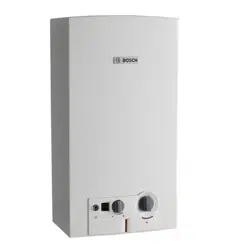
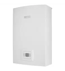
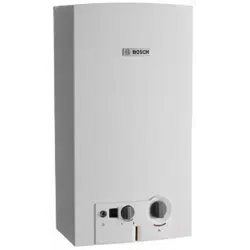
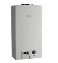
2.4 Description of the heater
Hot water unit for internal wall mounting only.
Natural draft appliance, requires adequate air supply.
No 240 volt required.
Available in Natural Gas or LP Gas.
• Hydrogenerator produces a small voltage to ignite and
control the water heater
• Water enters the hydrogenerator
• The turbine spins with the water flow through the unit
• A small voltage is generated by the turbine
• The voltage causes the ignition control unit to light a
temporary pilot
• The water pressure opens the main burner gas valve and
the pilot ignites the main burner, the pilot then goes out
• The water flows through the heat exchanger where it is
heated.
On / Off switch to allow customer to activate the appliance.
Safety devices
• Flame rod to check for accidental extinction of the burner
flame
• Over temperature switch to prevent overheating
• Flue safety device to shut of unit if flue spillage
Easily accessible water inlet filter.
Internal flue diverter, connection to external flue.
Fluing to be purchased by external supplier (refer to Bosch for
details of supplier).
Model GWH 10/13/16 -2 G..
Category CONTINUOUS FLOW
Type INTERNAL
Table 2
Type l/min Series Ignition Gas Types
GWH 10 2 G NG / LP gas
GWH 13 2 G NG / LP gas
GWH 16 2 G NG / LP gas
Table 3
6
Technical Characteristics and Dimensions
6 720 608 992 (2021/02)
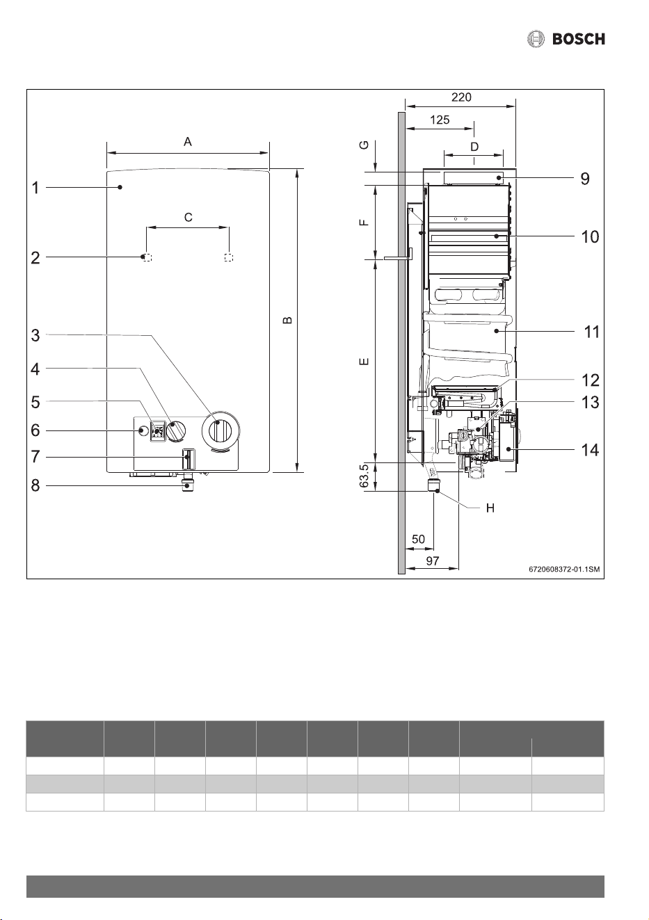
2.5 Dimensions
Fig. 1
[1] Front cover
[2] Opening in rear panel for mounting on the wall
[3] Temperature/volume selector
[4] Gas adjustment
[5] Digital display
[6] Switch/LED - Low water pressure indicator
[7] LED - Burner status check
[8] Gas connection
[9] Connection collar for flue
[10] Draught diverter
[11] Copper Heat exchanger
[12] Burner
[13] Gas valve
[14] Ignition unit
Dimensions
(mm)
A B C D E F G H (Ø)
Natural gas LP gas
GWH10... 310 580 228 115 463 60 25 20 15
GWH13... 350 655 228 140 510 95 30 20 15
GWH16... 425 655 334 140 540 65 30 20 15
Table 4 Dimensions
7
Technical Characteristics and Dimensions
6 720 608 992 (2021/02)
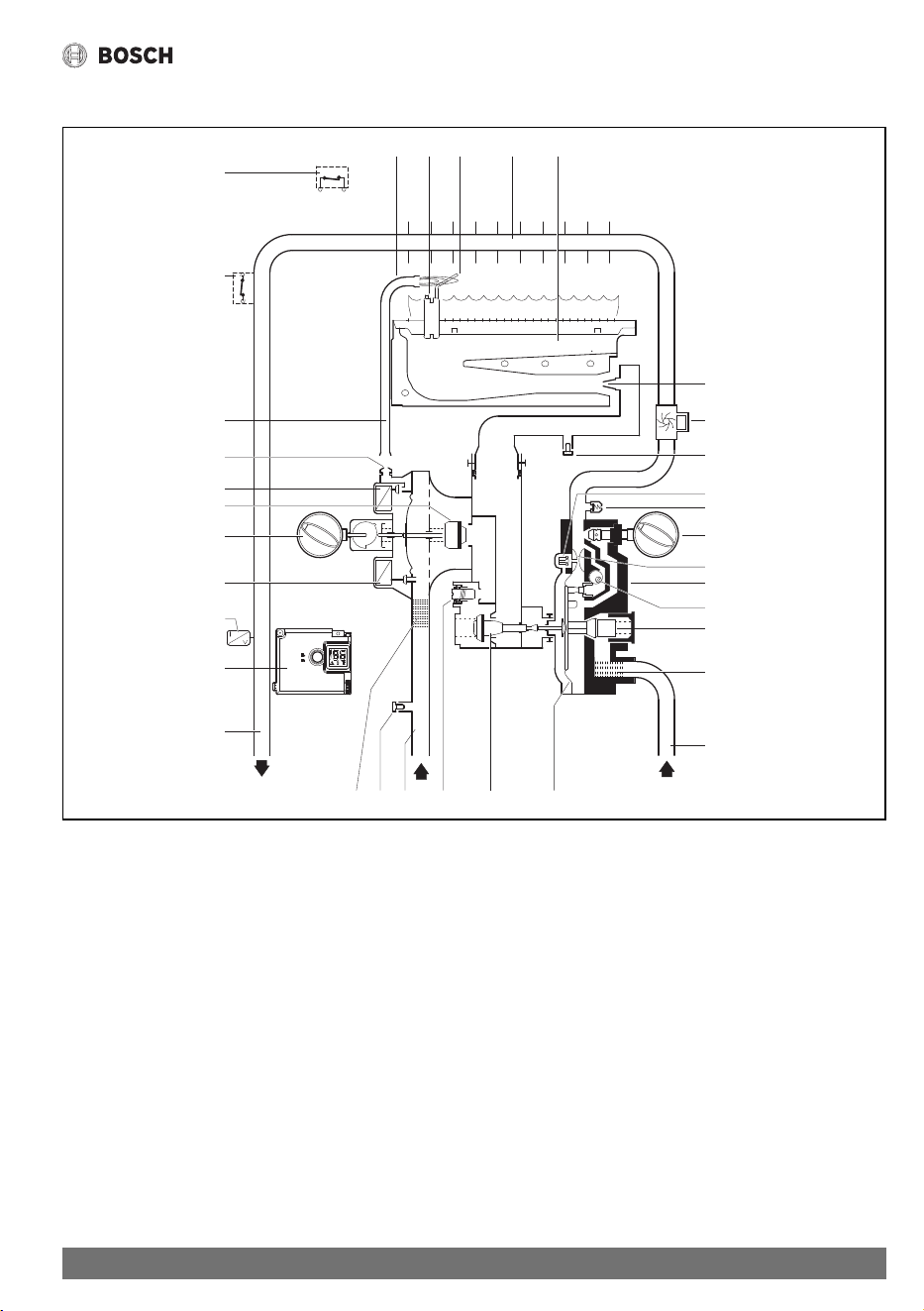
2.6 Functional diagram of the heater
Fig. 2 Functional diagram
[1] Pilot burner
[2] Ignition Electrode
[3] Ionisation probe
[4] Heat exchanger
[5] Main burner
[6] Injector
[7a] Burner pressure test point
[7b] Gas inlet pressure test point
[8] Slow ignition valve
[9] Venturi
[10] Temperature/volume selector
[11] Water valve
[12] Plunger
[13] Water flow regulator
[14] Water filter
[15] Hydrogenerator
[16] Cold water pipe
[17] Diaphragm
[18] Main gas valve
[19] Maximum gas adjusting screw
[20] Gas supply pipe
[21] Gas filter
[22] Hot water pipe
[23] Ignition unit
[24] Temperature sensor
[25] Servo valve
[26] Power selector
[27] Gas valve
[28] Pilot valve
[29] Pilot injector
[30] Pilot gas pipe
[31] Overtemperature switch
[32] Flue gas safety device
[33] Relief Valve/Drain screw
12
3
4
5
6
8
9
10
15
7a
11
12
13
14
16
171819207b21
23
22
25
24
26
27
28
29
30
31
32
33
6720608992-05.1V
8
Technical Characteristics and Dimensions
6 720 608 992 (2021/02)
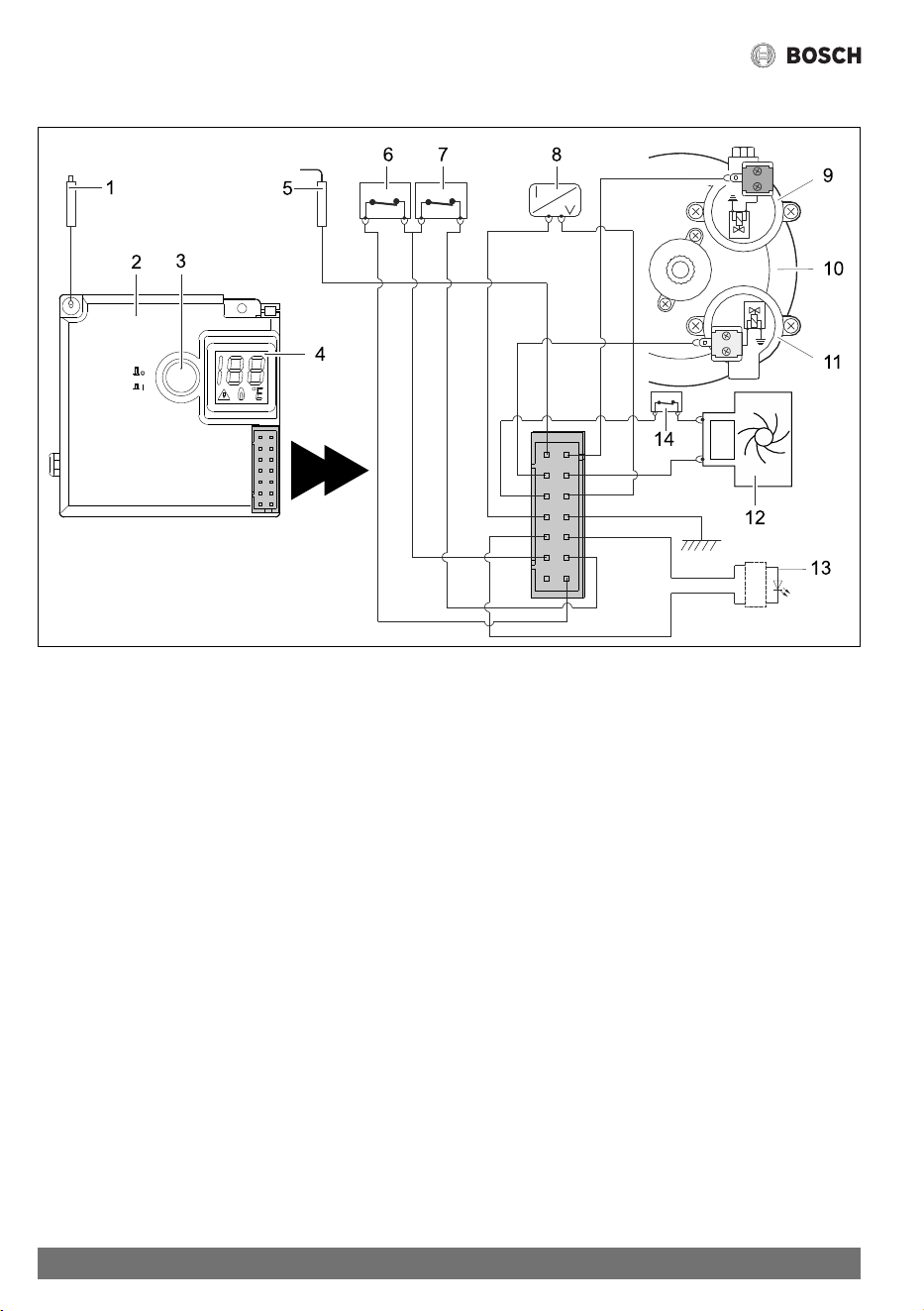
2.7 Electrical diagram
Fig. 3 Electrical diagram
[1] Ignition electrode
[2] Ignition unit
[3] Switch/LED - Low water pressure indicator
[4] Digital display
[5] Ionisation probe
[6] Flue gas safety device
[7] Overtemperature switch
[8] Temperature sensor
[9] Pilot solenoid (Normally Closed)
[10] Diaphragm valve
[11] Main Solenoid (Normally Open)
[12] Hydrogenerator
[13] LED - Burner status check
[14] Microswitch
2.8 Function
This gas heater is equipped with automatic electronic ignition
to simplify operation.
▶ To activate, just turn on the switch (Fig. 9).
After this, automatic ignition occurs whenever a hot water tap
is opened. First, the pilot burner is lit and approximately four
seconds later the main burner ignites. The pilot burner flame is
extinguished after the main burner lights.
This is a way of saving a great amount of energy as the pilot
burner only operates for the minimum necessary time to ignite
the main burner.
9
Regulations
6 720 608 992 (2021/02)
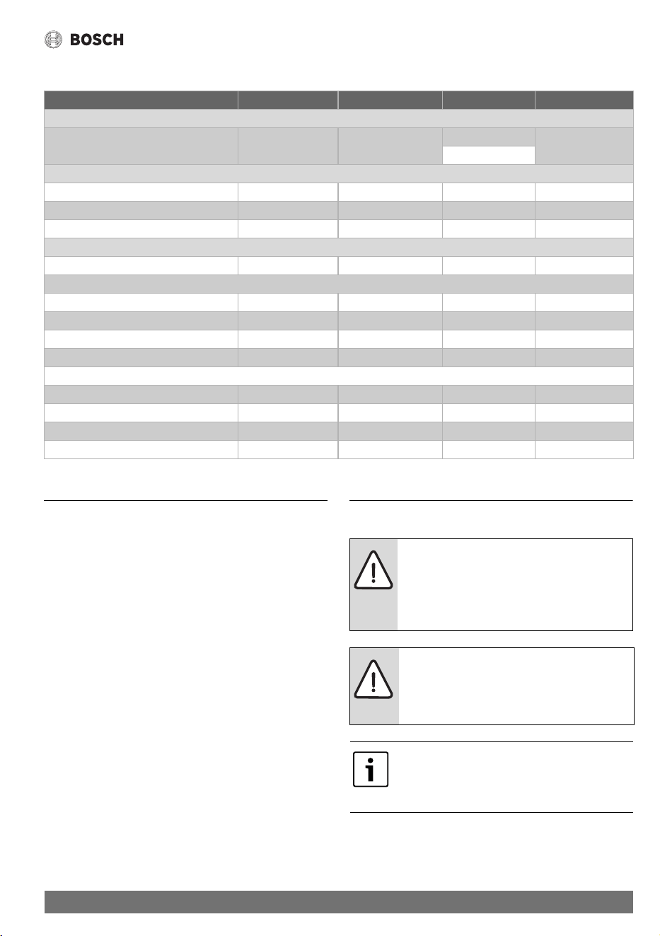
2.9 Technical characteristics
3Regulations
Any local by-laws and regulations pertaining to installation and
use of gas-heated appliances must be observed.
This appliance must be installed in accordance with the
manufacturers installation instructions, AS/NZS5601 and all
Local Building & Gas fitting regulations
It is recommended that for sanitary fixtures used for the
purpose of personal hygiene, that a temperature limiting
device be fitted (such as a tempering valve) as per AS/NZS
3500.1.9.3.
This appliance must not be installed in a bedroom, bathroom,
toilet, or combined living/sleeping room as per AS/NZS5601
5.12.5.2.
Failure to install this appliance in accordance with these
installation instructions will void the warranty.
Fluing is required to be installed in a vertical plane only, with no
bends. Please refer to fluing guidelines.
4 Installation
Technical characteristics Units GWH10 GWH13 GWH16
Gas Consumption
Nominal Gas Consumption MJ 79 100 (NG) 127
97 (LP gas)
Supply pressure
Natural gas H kPa 1.13 1.13 1.13
LP gas kPa 2.75 2.75 2.75
Number of injectors 12 14 18
Water data
Maximum permissible pressure kPa 1000 1000 1000
Temperature selector in fully clockwise position
Temperature rise °C 50 50 50
Flow range l/min 2.2 - 4.6 2.2 - 6.2 2.2 - 8.6
Minimum operating pressure kPa 35 35 50
Minimum pressure for maximum flow kPa 50 60 80
Temperature selector in fully anti-clockwise position
Temperature rise °C 25 25 25
Flow range l/min 4 - 10 4 - 13 4 - 15
Minimum operating pressure kPa 45 45 50
Minimum pressure for maximum flow kPa 100 140 170
Table 5
DANGER:
This appliance must not be installed in a
bedroom, bathroom, toilet or combined living/
sleeping room in accordance with AS/
NZS5601.
DANGER: Explosion Risk
▶ Always turn off the gas cock before
carrying out any work on components
which carry gas.
The gas installation, connection of the flue and
supply pipes, as well as the initial startup are to
be performed exclusively by an authorised
person.
10
Installation
6 720 608 992 (2021/02)
4.1 Important information
▶ Install in accordance with AS/NZS5601, AS/
NZS3500.4.2, NZS5261 and all local building, water and
gas fitting regulations particularly with regard to ventilation
requirements.
▶ Do not place articles on or against this appliance.
▶ Install gas and water isolation valves as close as possible to
the heater.
▶ After finishing the gas piping system, the pipes must be
thoroughly purged and leak-tested. To avoid damaging the
gas valve by excess pressure, this test must be performed
with the gas valve of the heater closed.
▶ Check if the heater corresponds to the type of gas
provided.
▶ Ensure adequate operating gas pressure and water
pressure (see technical data in the table 5).
4.2 Selection of the place of installation
Requirements regarding the place of installation
• Comply with the specific instructions for each State.
• Install the gas heater in a well-ventilated location where it
will not be exposed to temperatures below zero. Ensure
combustion gases are flued to outside atmosphere in
accordance with AS/NZS5601.
• To avoid corrosion, the combustion air must be free from
harmful substances. Examples of particularly corrosive
substances: halogenated hydrocarbons contained in
solvents, paints, glues, hairsprays and various domestic
detergents. If necessary, take adequate measures.
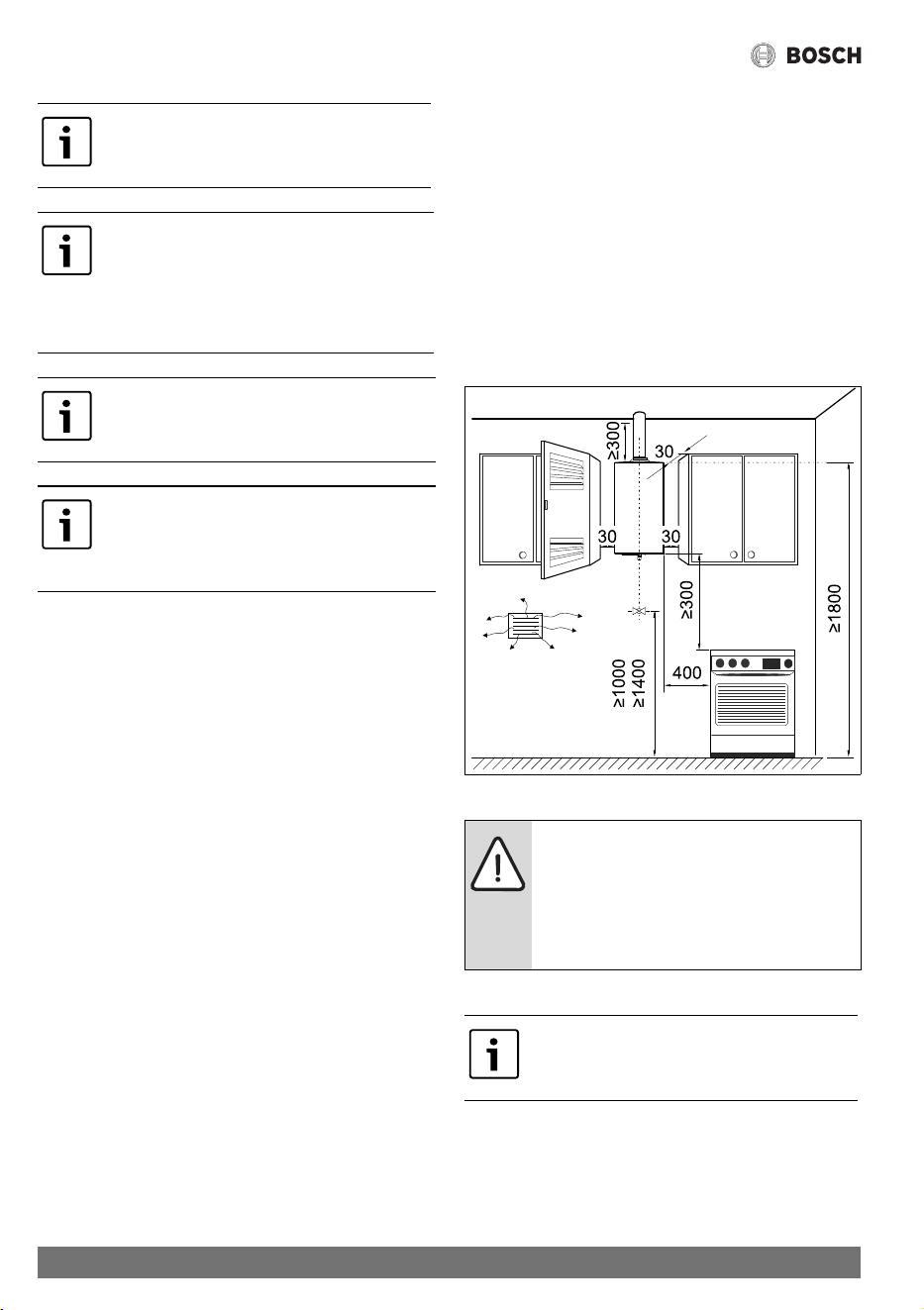
• Install the appliance in accordance with the minimum
installation clearances indicated in Fig. 4.
• The gas heater must not be installed over a heat source.
• Do not obstruct the openings at top and bottom of
appliance.
• Top and bottom areas must be clear from any obstacles at
least 300 mm.
In case of a frost risk:
▶ Turn off the heater.
▶ Drain the heater (see section 5.7)
Fig. 4 Minimum clearances (in mm)
Combustion gases
This appliance should only be installed in
applications where cold water temperature
does not exceed 40 °C.
The use of these heaters with water supply
pressure values below 50 kPa is not
recommended. This appliance requires a
minimum flow rate of 2.5lpm to operate.
Sufficient flow must be provided to ensure
correct operation of the appliance.
Installation in a marine environment should be
avoided.
Not suitable for pool, spa pool or solar
application.
Not suitable for commercial recirculating
systems.
DANGER:
Ventilation requirements as per AS/NZS5601.
Ensure not installed in a negative pressure
environment.
Negative pressure tests are required upon
installation to ensure adequate ventilation.
Use single or twin skin flue in accordance with
AS/NZS5601.
11
Installation
6 720 608 992 (2021/02)
If any of these conditions cannot be met, a different location
must be selected.
Surface temperature
The maximum surface temperature of the heater is less than
85 °C, with the exception of the flue piping. No special
protection measures are required for flammable construction
materials or built-in furniture items.
Air intake
The place where the heater is to be installed must have an
adequate air supply as per AS/NZS5601.
4.3 Heater mounting
▶ Remove the temperature/flow selector and the gas selector
knobs.
▶ Unscrew the cover fixing screws.
▶ With a simultaneous movement forwards and upwards,
release the cover from the two lugs at the back.
▶ Fix the heater vertically, using fixings appropriate for the
material & weight.
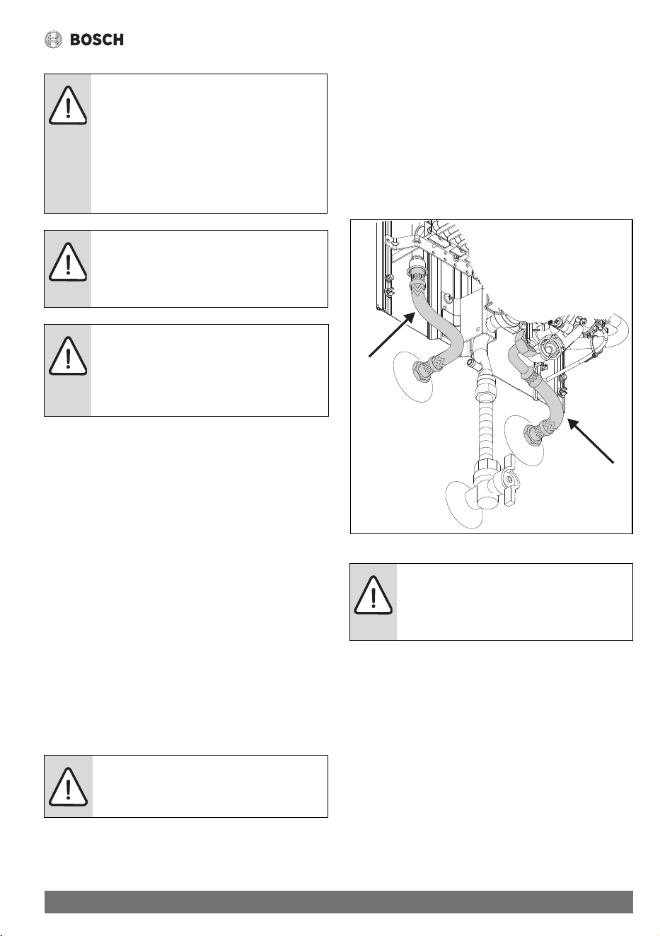
4.4 Water connection
It is advisable to purge the water pipes before connection,
because the presence of dirt may reduce the flow and, in
extreme cases, cause a blockage.
▶ Identify the cold water pipe (Fig. 5, [A]) and the hot water
pipe (Fig. 5, [B]), so as to avoid any possible cross-
connection.
▶ Connect the water pipes to the water valve using the
connection accessories provided.
Fig. 5 Water connection
4.5 Hydrogenerator operation
The hydrogenerator (hydrodynamic generator or HDG) is
located in the water circuit between the water valve and the
heat exchanger. This component has a turbine that rotates
when water flows past its blades. This movement is transmitted
to an electric generator which powers the heater ignition unit.
The electrical voltage value supplied by the HDG is
approximately 3.0 VAC.
4.6 Pressure Relief
The pressure relief (Fig. 2, [33]) will release pressure from the
system whenever the value exceeds 1500 kPa.
DANGER: Make sure that all flue connections
are sealed.
▶ Fit the flue pipe with an approved flue
cowl.
▶ Failure to follow this requirement may
cause dangerous exhaust gases to enter
living space which may result in personal
injury or loss of life.
DANGER:
All parts of flue must be vertical.
Please refer to fluing instructions.
Document number 6721830064.
CAUTION:
Ensure that the flue is installed to the
requirements of AS/NZS5601, including the
requirement to terminate the flue above the
roof level.
CAUTION:
Never support the gas heater on the water or
gas connections.
CAUTION:
The water inlet isolation valve must be a Gate
or Ball Valve, a Stop Cock or Non-Return Valve
must not be fitted.
B
A
6720608992-03.1Av

12
Installation
6 720 608 992 (2021/02)
4.7 Gas connection
Gas regulator
The appliance is supplied with a gas pressure regulator that
must be installed on the heater before attaching the gas supply
line (see Fig. 6). This is a requirement for both NG and LPG
installations.
▶ Use sealing tape to assure the complete tightness of the
installation.
Fig. 6 Gas regulator
4.8 Flue connection
▶ Please refer to the fluing guideline supplement for further
requirements and instructions.
Typical flue installation
Fig. 7 Flue connection
4.9 Testing
▶ Turn on the gas and water isolation valves and check all
connections for leaks. If all connections are sound then
follow procedures set out in Section 6 for adjustment of
Gas Pressures.
DANGER:
If local regulations are not followed, a fire or
explosion could result causing property
damage, personal injury, or loss of life.
Size gas supply as per AS/NZS5601.
Incorrect gas pipe sizing will not be covered by
the warranty.
Refer to directional arrow on regulator to ensure
correct orientation when fitting.
6720608992-02.1JS
WARNING:
Do not use an unlined masonry chimney as the
flue for this appliance.
13
Operating instructions
6 720 608 992 (2021/02)
5 Operating instructions
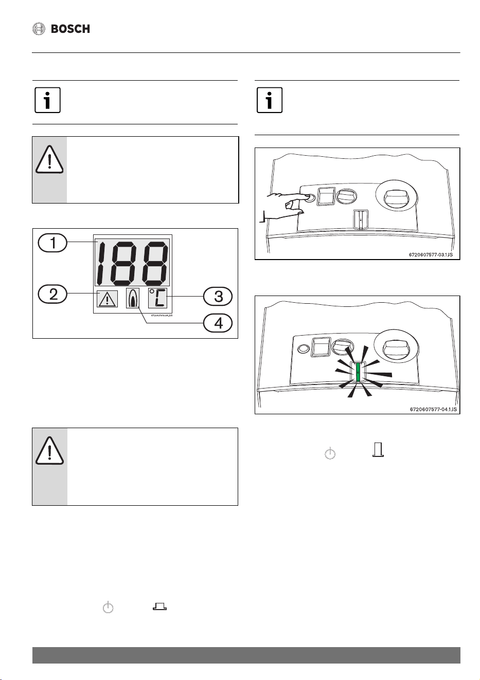
5.1 Digital display - description
Fig. 8 Digital display
[1] Temperature/error code
[2] Malfunction indicator
[3] Temperature measurement units
[4] Heater in operation (burner turned on)
5.2 Before starting up the heater
▶ Check if the gas indicated on the rating plate is the same as
the one used at the location.
▶ Open the gas valve.
▶ Open the water valve.
5.3 Turning the heater on and off
Turning on
▶ Press the switch , position .
Fig. 9
Turn Hot Tap on, LED light on = Main burner on
Fig. 10
Turning off
▶ Press the switch , position .
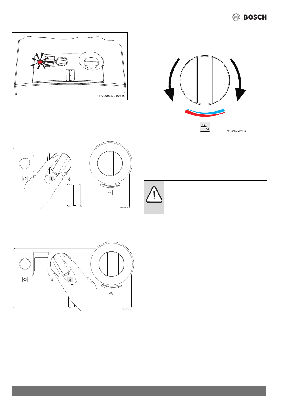
5.4 Water flow
If the red LED starts flashing during operation, check the water
flow.
Open all water and gas isolation valves.
Purge the pipes.
CAUTION:
The front stainless steel panel in the burner and
pilot burner area may reach high
temperatures, with risk of burning in case of
contact, and must not be removed.
CAUTION:
▶ Initial startup must be performed by an
authorised gas fitter who will provide the
customer with all the necessary
information for optimum operation of the
gas heater.
Only press switch with no water flowing
(activation of the switch with water flowing will
result in an FO fault. Turn the flow off then on to
clear fault).
14
Operating instructions
6 720 608 992 (2021/02)
Fig. 11
5.5 Gas adjustment
Lower water temperature.
Use less gas.
Fig. 12
Higher water temperature.
Use more gas.
Fig. 13
5.6 Temperature/flow adjustment
▶Turn anti-clockwise
Increases flow and decreases water temperature.
Fig. 14
▶Turn clockwise.
Decreases flow and increases water temperature.
Regulating the temperature to the minimum required value
reduces energy consumption.
CAUTION:
The temperature on the display is not precise,
always check before bathing children or elderly
people.
15
Commissioning
6 720 608 992 (2021/02)
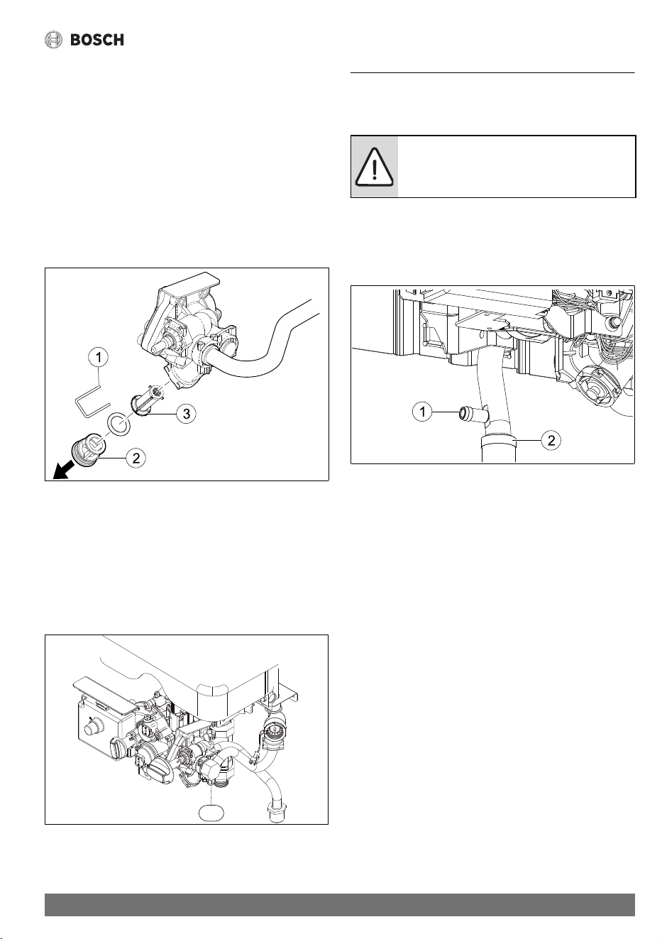
5.7 Draining the appliance
There are two ways to drain the appliance if there is a risk of
freezing.
After turning off the inlet water valve and gas supply, open a hot
water tap to relieve pressure then proceed as follows:
Water valve draining (see fig 14)
▶ Remove the fixing lock [1] from the filter screw cap [2]
situated in the water valve.
▶ Remove the filter screw cap from the water valve.
▶ Carefully remove the water filter [3].
▶ Empty all the water contained in the heater.
Fig. 15 Draining
[1] Lock
[2] Filter screw cap
[3] Water filter
Cold water inlet pipe drain (see fig 15)
▶ Remove the pressure relief screw (no. 1) situated in the
water inlet pipe.
▶ Drain all the water contained in the heater.
Fig. 16 Draining
[1] pressure relief screw
6 Commissioning
6.1 Inlet pressure adjustment
Burner pressures have been adjusted in the factory, however
adjustment may be required upon installation.
Attach a manometer to the inlet pressure test point [1] located
on the gas inlet pipe [2].
Fig. 17 Gas inlet pressure test point
Inlet gas pressure should be adjusted at the appliance regulator
to 1.13 kPa for Natural Gas and 2.75 kPa for LP gas.
These measurements must be set while the unit is operating,
with the water valve fully clockwise (minimum flow) and the gas
valve fully anti-clockwise (maximum gas).
1
6720608992-04.1Av
DANGER:
The following procedures must only be
performed by a qualified technician.
16
Maintenance
6 720 608 992 (2021/02)
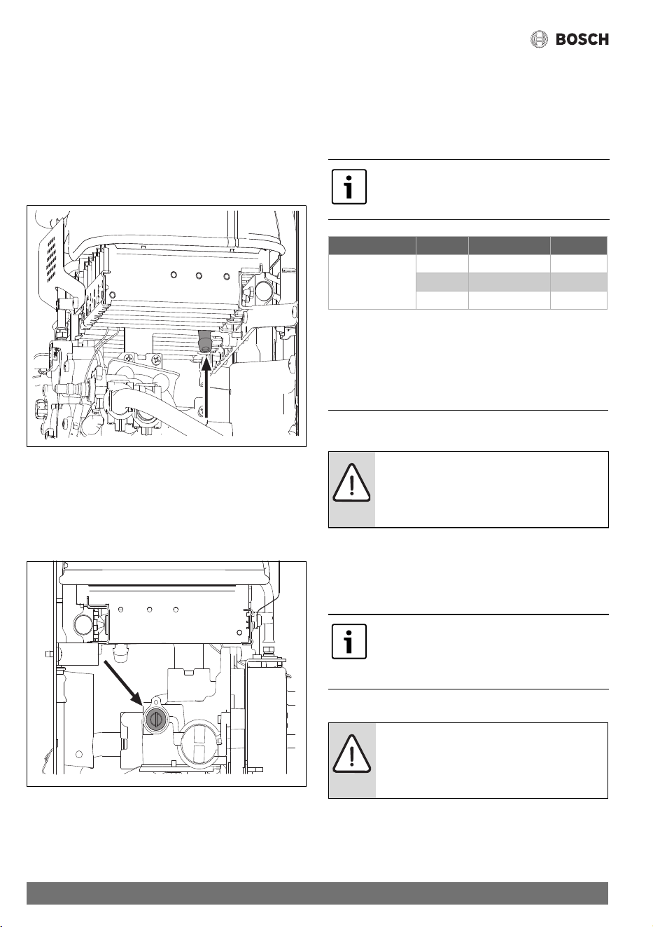
6.2 Burner pressure adjustment
Accessing the adjusting screw
▶ Remove the front cover from the heater (see 4.3).
Connecting the manometer
▶ loosen the burner test point captive screw (Fig. 18).
▶ Connect the manometer to the burner pressure measuring
point.
Fig. 18 Pressure measurement point
Maximum gas flow adjustment
▶ Remove the seal from the adjusting screw (Fig. 19).
▶ Turn on the heater with the gas adjustment set to maximum
(anti clockwise) and the water flow adjustment set to
minimum (clockwise).
Fig. 19 Maximum gas flow adjusting screw
▶ Open various hot water taps.
▶ Using the adjusting screw (Fig. 19), regulate the gas
pressure until the values indicated in the table 6 are
achieved.
▶ Seal the adjusting screw once again.
Minimum gas flow adjustment
6.3 Conversion to a different type of gas
It is not recommended to convert these units to a different gas
type.
7 Maintenance
To ensure that gas consumption and the environmental load
(pollution, etc.) remain as negligible as possible over time, we
recommend the appliance be maintained on an annual basis.
These jobs can only be done by a qualified technician.
7.1 Flue gas safety device
Operation and precautions
This probe verifies the condition of flue gas evacuation and, in
case of malfunction, it automatically turns off the heater. This
6720607418-01.3V
6720607418-02.2V
The minimum gas flow adjustment is performed
automatically after the adjustment of the
maximum gas flow.
Natural gas H LP gas
MAX Burner
Pressure (kPa)
GWH10 0.69 2.00
GWH13 0.66 1.90
GWH16 0.44 2.20
Table 6 Burner pressure
DANGER:
Failure to perform maintenance procedures
can lead to appliance malfunction, errors,
service calls and loss of warranty.
Maintenance must only be performed by a
qualified technician. Maintenance information
is contained in a service manual available to
licenced technicians upon request from Bosch.
DANGER:
The probe must never be turned off, modified
or replaced with a different part under any
circumstances.
17
Maintenance
6 720 608 992 (2021/02)
prevents combustion gases from entering the room where the
gas heater has been installed. The probe restarts after a reset
period.
If the heater turns off during operation:
▶ Ventilate the room.
▶ After 10 minutes, turn on the heater once again.
Call a qualified technician if the same thing happens again.
Service Checklist
Water valve
• Diaphragm, replace if required
• Water throttle, greased, O-rings replaced if required
• Water filter, cleaned, replaced if required
• Sleeve, greased, replaced if required
• Water governor, clean
Gas valve
• Pilot burner cleaned
•Flame rod cleaned
• Main burner, injectors and venturies cleaned
Hydrogenerator
• Inlet clear of obstructions
Heat exchanger
•Fins cleaned
• Water connections checked and tightened
Gas pressure
• Burner pressures checked and adjusted
• Check inlet operating pressure
Flue
•Check for obstructions and tightness
• Negative pressure test
DANGER:
The user must never touch the flue gas safety
device.
18
Problems
6 720 608 992 (2021/02)
8Problems
8.1 Problem/cause/solution
Assembly, maintenance and repairs must be performed by qualified technicians only. The following chart offers solutions to
possible problems.
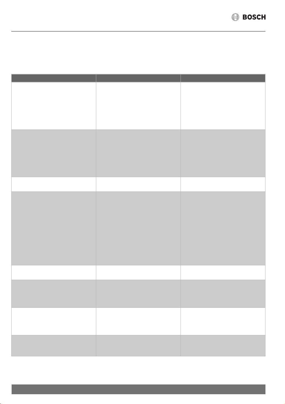
Problem Cause Solution
The heater does not ignite and digital
display is turned off.
Slow and difficult ignition of the burner.
Red LED in switch flashes.
Switch turned off.
Reduced water flow.
Reduced water flow.
Check switch position.
Call a qualified technician.
Call a qualified technician.
Water at low temperature. Check the temperature selector position
and adjust it according to the desired
water temperature.
Insufficient gas supply.
Call a qualified technician.
Water is not heated, no flame. Insufficient gas supply. Gas Cylinders may
be empty
If sufficient gas appears to be available call
a qualified technician.
Digital display shows “E9”.
Digital display shows “A4”.
Temperature limiter has tripped
Flue gas safety device has tripped
Wait 10 minutes and restart the heater. If
the problem persists, call a qualified
technician.
Vent the area. Wait 10 minutes and restart
the heater. If the problem persists, check:
- Is fluing correct?
- Adequate ventilation?
- Negative pressure environment?
Call a qualified technician.
Incorrect temperature information in the
appliance digital display.
Insuficient contact of the temperature
sensor.
Call a qualified technician.
Digital display shows “E1”. Water temperature sensor has tripped
(outlet water temperature above 85 °C).
Reduce the water temperature using the
gas and/or temperature adjustment
selector. If the problem persists, call a
qualified technician.
Digital display shows “A7”. Temperature sensor incorrectly
connected.
Temperature sensor defective.
Call a qualified technician.
Call a qualified technician.
Digital display shows “E0”. Ignition failure. Refer to EA solution.
Call a qualified technician.
Table 7

19
Problems
6 720 608 992 (2021/02)
Digital display shows “EA”. There is spark but the main burner does
not ignite, heater blocked.No ionisation
probe signal.
Check:
• Gas supply, position of valves, empty
LP gas cylinders.
Digital display shows “F0”. Power was activated with a hot water tap
running.
Turn the water off and on. If the problem
persists, call a qualified technician.
Digital display shows “F7”. False Flame. Check for water tightness of flue.
Ensure no rain ingress.
Call a qualified technician.
Reduced water flow. Insufficient water supply pressure.
Dirty taps or mixers.
Gas valve blocked.
Heat exchanger blocked (limescale).
Call a qualified technician.
Call a qualified technician
Call a qualified technician
Call a qualified technician
Problem Cause Solution
Table 7

20
Environmental protection
6 720 608 992 (2021/02)
9 Environmental protection
Environmental protection is a basic company strategy of
Bosch. The quality of our products, profitability and
environmental protection are equal-ranking goals for us. Laws
and regulations concerning environmental protection are
strictly observed. We use the best possible technology and
materials, under economic considerations, to protect the
environment.
Packaging
We participate in the recycling program of the respective
country to ensure optimal recycling. All of our packaging
materials are environmental-friendly and can be recycled.
Old appliances
Old appliances contain valuable materials that should be
recycled. The assemblies can be easily detached and synthetic
materials are marked accordingly. The assemblies can
therefore be sorted out and passed on for recycling or disposal.
21
Water quality
6 720 608 992 (2021/02)
10 Water quality
All Bosch water heating appliances are constructed from high
quality materials and components and all are certified for
compliance with relevant parts of Australian and New Zealand
gas, electrical and water standards.
Whilst Bosch water heaters are warranted against defects, the
warranty is conditional upon correct installation and use, in
accordance with detailed instructions provided with the
heater. In the case of the water supplied to the heater, it is
important that the water quality be of acceptable standard.
The water quality limits/parameters listed in water quality table
are considered acceptable and generally, Australian and New
Zealand suburban water supplies fall within these limits/
parameters.
In areas of Australia and New Zealand where water may be
supplied, either fully or partly, from bores, artesian wells or
similar, one or more of the important limits may well be
exceeded and the heater could, therefore, be at risk of failure.
Where uncertainty exists concerning water quality, intending
appliance users should seek a water analysis from the water
supplying authority and in cases where it is established that the
water supply does not meet the quality requirements of the
water quality table, the Bosch warranty would not apply.
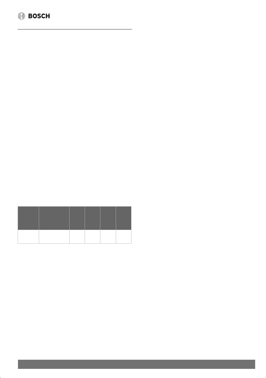
Water quality table
Maximum levels
pH
Saturation
Index(LSI)
(langelier)
Total
Hardness
Chlorides
Sodium
Iron
6.5-9.0 +0.4 to -1.0 at
65 °C
200
mg/l
250
mg/l
180
mg/l
1
mg/l
Table 8
22
Warranty details
6 720 608 992 (2021/02)
11 Warranty details
Robert Bosch (Australia) Pty Ltd
Thermotechnology Division
Voluntary Repair or Replacement Warranty
All Bosch products are carefully checked, tested and certified to Australian and New Zealand standards.
Important Note: Mandatory Australian Consumer Law statement
If you have purchased your product in Australia, you should be aware that:
This warranty is provided in addition to other rights and remedies held by a consumer at law. Our goods come with guarantees that
cannot be excluded under the Australian Consumer Law. You are entitled to a replacement or refund for a major failure and for
compensation for any other reasonably foreseeable loss or damage. You are also entitled to have the goods repaired or replaced if
the goods fail to be of acceptable quality and the failure does not amount to a major failure.
Important Note: New Zealand law
If you have purchased your product in New Zealand, you should be aware that:
This warranty is supplemental to any other rights and remedies you have under the Consumer Guarantees Act 1993 NZ, unless your
purchase is made for commercial purposes, in which case Bosch excludes all consumer guarantees implied in the Consumer
Guarantees Act 1993 NZ in respect of your product.
Warranty
Bosch warrants, at its option, to repair or replace your water heater or relevant part thereof (Product) if such Product are faulty or
defective in manufacture or materials during the warranty period specified below.
The warranty period commences on the date of purchase. If the date of original purchase cannot be determined, then the warranty
period will commence six (6) months after the date of manufacture stamped on the Product. Bosch may require evidence to verify
the date of purchase.
This warranty only covers repair or replacement of defective Product (including labour costs where indicated). It does not cover:
• any costs incurred by the end user in normal or scheduled maintenance of the Product; or
• subject to any law to the contrary, any damage to property, personal injury, direct or indirect loss, consequential losses or other
expenses arising from breach of this warranty. Any end user concerned with this exclusion should consider the "Important Note:
Mandatory Australian Consumer Law statement” above
Warranty Period and Coverage
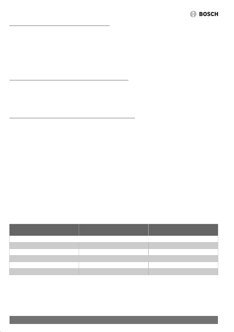
Bosch will provide warranty service for Product purchased and installed in Australia and New Zealand as follows.
"Parts & Labour" means free of charge repair and/or
replacement, including labour.
"Parts only" means a replacement heat exchanger, free of
charge. All installation and repair labour costs are the
responsibility of the owner.
Components The period after purchase within which
the fault must appear
What Bosch will do (see below for
definitions)
Domestic Use (see below for definition)
All components Year [1 to 2] Parts & Labour
Heat exchanger Year [3 to 10] Parts only
Commercial Use (see below for definition)
All components Year [1] Parts & Labour
Heat exchanger Year [1] Parts only
Table 9

23
Warranty details
6 720 608 992 (2021/02)
"Domestic use" warranty period applies to Product installed to supply hot water for use by individuals in domestic dwellings. For
Product used for all other uses, the commercial use warranty period will apply. This includes, without limitation, installations such
as centralised or bulk hot systems, hotels, sporting complexes, caravan parks, laundry facilities, restaurants and cafes.
For “Parts only” warranty, the end user will be charged for service call costs and service technician fees in effecting the replacement.
For valid claims within "Parts & Labour" warranty periods, the end user will not be charged for costs associated with making a
warranty claim, including service call costs, any service technician fees or the cost of replacement parts and freight, provided that:
• the Product is located within the usual operating area of an authorised service technician; and
• the Product has been installed according to the installation instructions so as to provide adequate service access
If the Product is not located within the usual operating area of an authorised service technician, the end user will be required to pay
the service call costs associated with a service call under this voluntary warranty.
Notwithstanding the above, if the Product has not been installed in accordance with the installation instructions in regards to
access, or has been otherwise installed in location where service access is difficult, the end user will be required to pay charges
associated with the difficult access. This includes, but is not limited to, the removal of walls or doors to gain access and the use of
specialised equipment to move the Product or components to safe working levels. Where the Product cannot be safely accessed,
Bosch may refuse to service the Product under this voluntary warranty.
For invalid claims under this voluntary warranty, the end user will be liable for the costs of making the warranty claim including any
service call costs.
Warranty Conditions
This voluntary warranty is subject to the following conditions:
• The Product must have been installed and correctly commissioned by an authorised and licensed installer in compliance with
applicable Australian Plumbing and Gas Standards. Proof may be required of correct commissioning of the Product (such as
certificate of compliance). Claims for failures due to incorrect installation or commissioning are not covered under this
voluntary warranty and may be rejected by Bosch.
• Where a Product or part thereof is replaced or repaired under this voluntary warranty, the balance of the original voluntary
warranty will apply. The replacement Product or part does not carry a new voluntary warranty.
• The Product must have its original serial numbers and rating labels intact.
• The warranty does not extend to any Product that have been completely or partially disassembled.
• These warranty terms cannot be amended except in writing by an authorised officer of Bosch.
• The warranty only applies to Product installed for an end user in Australia or New Zealand and purchased from Bosch or from a
reseller where the Product have been originally sold by Bosch.
• Any claim made under this voluntary warranty meets the requirements set out below in the “How to Make a Warranty Claim”
section.
Warranty Exclusions
This warranty will not apply to a defect or fault to the extent to which it arises:
• due to storage, handling or installation of the Product otherwise than in accordance with instructions provided for the Product
by Bosch or without reasonable care, including installation of a Product which is of inappropriate size or type for the intended
purpose;
• due to operation, use or maintenance of the Product otherwise than in accordance with instructions provided for the Product
by Bosch or without reasonable care, including use of the Product with faulty or unsuitable plumbing, water pressure, power or
gas supply;
• due to accidental damage or use of the Product for a purpose or in environmental conditions for which the Product were not
designed or sold, or use of the products outside the specified or normal operating ranges for such Product.
• as a result of changes which occur in the condition or operational qualities of the Product due to climate or other environmental
influence, foreign material contamination or water entry or as a result of exposure to excessive heat or solvents or because of
use of non-potable water or bore water in the Product or damage as result of an Act of Nature including but not limited to storms,
fires, floods and lightning strikes;
• from normal wear and tear or when replacement or repair of parts would be part of normal maintenance or service of the Product
or where the damage is only to surface coating, varnish or enamel;

24
Warranty details
6 720 608 992 (2021/02)
• as a result of repairs, alterations or modifications to the Product which have been performed by a person who is not suitably
qualified and experienced to perform works on the Product; or
• from the use of any spare parts not manufactured, sold or approved by Bosch in connection with the repair or replacement of
Product.
This voluntary warranty does not apply to damage that has been caused by continued use of a Product after it is known, or would
have been known with regular servicing, it is defective.
Wrong Deliveries and Transit Damage
Wrong deliveries, incorrect or damaged packing and transit damage claims are not warranty claims. Such cases should be directed
to Bosch's Customer Service line in Australia on ph: 1300 307 037 or in New Zealand on ph: 0800 543 352.
How to Make a Warranty Claim
If a Product fails within the warranty period, the end user must stop using the Product and make a claim as soon as possible, in any
event before the end of the Warranty Period (see Deadlines for Submitting Warranty Claims below).
To make a warranty claim under this voluntary warranty, call the Bosch Customer Contact Centre (in Australia on ph: 1300 307 037
or in New Zealand on ph: 0800 543 352). Please be ready to provide the model and serial number, date of installation, purchase
details and a full description of the problem. Alternatively, for claims in Australia, you can post details of your claim to Robert Bosch
(Aust) Pty Ltd, Attn TT Warranty Department, Locked Bag 66, Clayton Sth, Victoria, 3169. Claims received by post will take longer
to process and we encourage you to call. Bosch may refer you to one of its Bosch Warranty Authorised Service Dealers.
Proof of purchase and purchase date, as well as proof of installation and proper commissioning by a licensed installer, may be
required by Bosch or an authorised service technician.
All warranty service calls will be conducted by an authorised service technician during normal business hours. Bosch will not accept
claims under this voluntary warranty for attendance and repair of the Product by third parties not authorised by Bosch.
Deadlines for Submitting Warranty Claims
Bosch aims to rectify genuine quality problems as a priority. This is generally achieved by investigating why defective products have
failed and by introducing immediate corrective action measures to prevent re-occurring warranty failures. It is therefore critical that
all warranty claims are promptly submitted to Bosch as soon as the product fails, and in any event before the end of the warranty
period.
Product Liability and Product Safety
Bosch should be informed immediately about any potential product safety concerns within and outside the warranty period. Bosch
is well aware of its product liability and product safety obligations and responsibilities. It is our aim to ensure appropriate product
safety standards are met in order to avoid injury, loss and damage caused by defects in any Product.
Privacy
Bosch is required to seek personal information from an end user who seeks to make a claim under this warranty.
Such personal information may be used by Bosch and/or any authorised service technician (who is authorised to process warranty
claims and/or carry out warranty repairs on behalf of Bosch) for the purpose of processing such warranty claim and also for the
provision of customer support and further information about Bosch’s products and services (Purpose).
If an end user does not wish to provide Bosch and/or its authorised service technician with personal information, Bosch may be
unable to process the end user’s warranty claim or to provide the end user with additional customer support, services and
information.
Bosch is committed to protecting the privacy of personal information and will act in compliance with applicable privacy laws,
including the National Privacy Principles under the Australian Privacy Act 1988 (Cth) (as amended) and New Zealand’s Information
Privacy Principles described in the Privacy Act 1993 (NZ).
Failure to service Product in accordance with recommendations in instruction manuals for Product may result in a warranty claim
under this voluntary warranty being rejected by Bosch. Bosch alerts end users that instruction manuals for Product contain
specific recommendations for servicing and safety checks to be carried out on Product.
Table 10

25
Warranty details
6 720 608 992 (2021/02)
Bosch takes security measures in order to protect any personal information collected in the warranty claim process against
manipulation, loss, destruction, access by unauthorized persons or unauthorized disclosure.
Bosch will not disclose any personal information to third parties other than for the Purpose or except as required by law.
An end user has the right to access the personal information Bosch or its authorised service technician hold about them. The end
user can request to see, change or modify the personal information held about them, or withdraw consent for its usage, by
contacting Bosch at the Bosch Contact Details below.
Bosch Contact Details
This warranty is offered by Robert Bosch (Australia) Pty Ltd (ACN 004 315 628) of 1555 Centre Road, Clayton, Victoria 3168.
Please call the Customer Contact Centre on 1300 30 70 37 in Australia or 0800 543 352 in New Zealand if you have any queries
in relation to this warranty or contact us using the online form at www.bosch-thermotechnology.com.au
.

26 6 720 608 992 (2021/02)
Notes

276 720 608 992 (2021/02)
Notes

6720608992