Multi-Zone
Service Manual
Ductless Multi-Split Heat Pumps
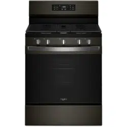
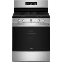
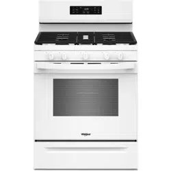
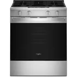
Appearances vary by model Appearances vary by model
• Please read this manual before using the heat pump.
• Keep this user manual for future reference.
Before troubleshooting or servicing equipment, review equipment
installation guides and conrm ALL installation requirements
& specications have been met. Including, but not limited to:
wiring, clearance, ducting (where applicable), power, and line set
requirements. Correct any installation issues before continuing.
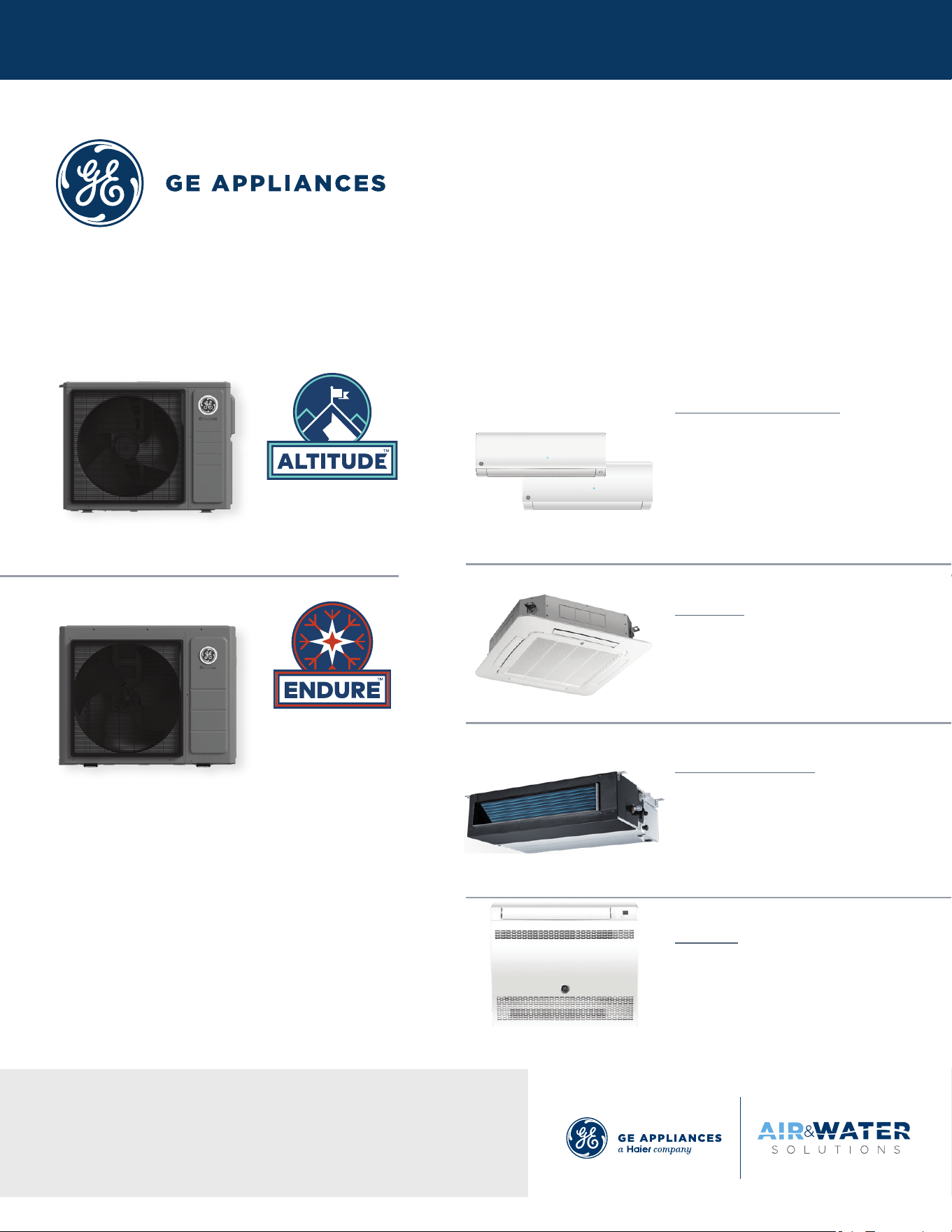
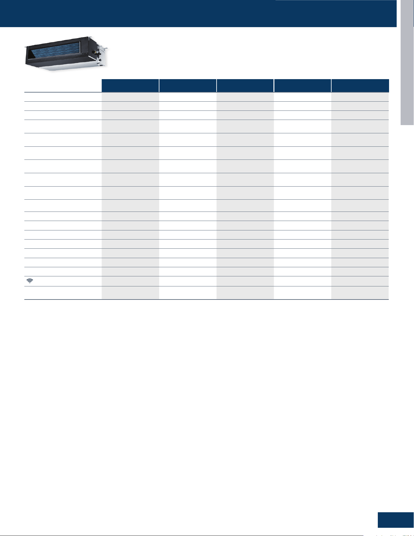
Outdoor Models Indoor Models
2G20ED2BEA
3G24ED2BEA
4G36ED2BEA
5G42ED2BEA
Wall Mount - Highwall
GS07WB2BEA
GS09WB2BEA
GS12WB2BEA
GS15WB2BEA
GS18WB2BEA
GS24WB2BEA
Cassette
US09CB2BEA
US12CB2BEA
US18CB2BEA
US24LB2BEA
Mid-Static Ducted
US07MB2BEA
US09MB2BEA
US12MB2BEA
US18MB2BEA
US24MB2BEA
Console
US09FB2BEA
US12FB2BEA
US18FB2BEA
GS09WP2BEA
GS12WP2BEA
GS18WP2BEA
GS24WP2BEA
Model Lineup:
2G18AD2BEA
3G24AD2BEA
4G36AD2BEA

INTRODUCTION
2
ENGLISH
TABLE OF CONTENTS
Introduction ................................................................................................................. A1
Outdoor Units
...............................................................................................................B1
Highwalls
..................................................................................................................... C1
Cassettes
..................................................................................................................... D1
Console
......................................................................................................................... E1
Mid-Static Ducted
.........................................................................................................F1
Troubleshooting And Reference
................................................................................... G1
10-16-25: Edition release.

INTRODUCTION
INTRODUCTION
A1
ENGLISH
TABLE OF CONTENTS
SAFETY & PRECAUTIONS .......................................................................................................................................................A2
SPECIFICATIONS
....................................................................................................................................................................A3
Outdoor Units ........................................................................................................................................................................A3
Highwall Indoor ......................................................................................................................................................................A5
Cassette Indoor .....................................................................................................................................................................A6
Console Indoor .......................................................................................................................................................................A6
Ducted Indoor ........................................................................................................................................................................A7
FUNCTIONS AND CONTROL ..................................................................................................................................................A8
Error Code Detection .............................................................................................................................................................A8
Antifreezing Protection Indoor ..............................................................................................................................................A8
When the Compressor First Starts ........................................................................................................................................A8
The Outdoor Fan Control (Exchange Fan) .............................................................................................................................A8
The Outdoor Fan Control When In Cooling or Dehumidifying Mode ...................................................................................A8
The Control of the Outdoor Unit Expansion Valve ...............................................................................................................A8
Four-Way Valve Control .......................................................................................................................................................... A8
Anti-freezing Protection (Highwall Only) ..............................................................................................................................A8
Resumption of Operation After Power Loss .........................................................................................................................A8
Over-Temperature Heat Mode Indoor Coil ...........................................................................................................................A9
Base Pan Heater Operating Logic and Testing Process........................................................................................................A9
Compressor Heater Band Operating Logic and Testing ....................................................................................................A10
Sleep Mode ...........................................................................................................................................................................A10
Enhanced Defrost Mode ......................................................................................................................................................A10
ECO Function ........................................................................................................................................................................A10
Dry Mode (Dehumidifying Mode) .........................................................................................................................................A11
EmergencyFunction(EmergencyPowerTurn-OButton) ...............................................................................................A11
Forced Heating/Cooling Modes ...........................................................................................................................................A11
WiFi....... .................................................................................................................................................................................A11
Setting Temperature Compensation ..................................................................................................................................A11
INTRODUCTION
A2
ENGLISH
SAFETY & PRECAUTIONS
FOLLOW ALL WARNINGS, CAUTIONS, AND PRECAUTIONS BELOW, AND INDUSTRY BEST
SAFETY PRACTICES AND STANDARDS. FAILURE TO DO SO MAY RESULT IN EQUIPMENT
DAMAGE OR FAILURE, AND SERIOUS PERSONAL INJURY OR DEATH.
!
WARNINGS
Service should be performed by the dealer or another professional.
Improperservicemaycausewaterleakage,electricalshock,orre.
Use only the supplied or specied service parts.
Useofotherpartsmaycausetheunittocomelose,waterleakage,electricalshock,orre.
The heat pump must be installed on a solid base that can support the unit’s weight.
Aninadequatebaseorincompleteinstallationmaycauseinjuryintheeventtheunitfallsothebase.
Electrical work should be carried out in accordance with the manual and national/local electrical wiring codes and rules of practice.
Insucientcapacityorincompleteelectricalworkmaycauseelectricalshockorre.
A dedicated power circuit must be used. The power supply should NEVER be shared by another appliance.
Wiring cable must be long enough to cover the entire distance with no splices.
Do not use an extension cord. Do not put other loads on the power supply, use a dedicated power circuit.
Failuretodosomaycauseabnormalheat,electricshockorre.
Only the specied wire types may be used for electrical connections between the indoor and outdoor units.
Firmly clamp the interconnecting wires so they receive no external stresses. Incomplete connections or clamping may cause terminal
overheatingorre.
Wiring must not put undue stress or tension on the electrical covers or panels.
Installcoversoverthewires.Incompletecoverinstallationmaycauseterminaloverheating,electricalshock,orre.
If any refrigerant has leaked out during service work, ventilate the room.
Therefrigerantproducesatoxicgasifexposedtoame.
After all service is complete, check for and repair any system refrigerant leaks.
Therefrigerantproducesatoxicgasifexposedtoames.
When servicing or relocating the system, keep the refrigerant circuit free from substances other than the specied refrigerant
(R454B), such as air or moisture
The presence of air or other foreign substance in the refrigerant circuit causes an abnormal pressure rise or rupture, resulting in injury.
During pump-down, stop the compressor before removing the refrigerant piping.
If the compressor is still running, and the stop valve is open during pump-down, air will be sucked into the system while the compressor
is running. This will cause abnormal pressure and noncondensables added to the system.
Unit must NOT be grounded to a utility pipe, arrester, or telephone line ground.
Ancompletegroundmaycauseelectricalshock,orre.Ahighsurgecurrentfromlightningorothersourcesmaycausedamagetothe
heat pump.
CAUTIONS
The heat pump must not be installed in a place where there is danger of exposure to ammable gas.
Ifthegasbuildsuparoundtheunit,itmaycatchre.
Drain piping must comply with installation guidelines.
Inadequatepipingmaycauseooding.
Tighten are nuts according to the specied torque using a torque wrench.
Ifarenutsareovertightened,theymayeventuallycrackandcauserefrigerantleakage.
Ensure proper clearances around unit per installation guidelines.
INTRODUCTION
A3
ENGLISH
SPECIFICATIONS
Ourcontinuedcommitmenttoqualityproductsmaymeanachangeinspecicationswithoutnotice.
VisitGEAppliancesAirandWater.comtoaccesscurrentspecicationtablesonline.
NOTE
2 Zones 3 Zones 4 Zones
2G18AD2BEA 3G24AD2BEA 4G36AD2BEA
Cooling
Non-Ducted
Rated Capacity Btu/hr 18,000 24,000 35,000
Capacity Range Btu/hr 4,000-19,000 4,000-25,000 6,500-36,000
SEER2 22.5 24.0 20.0
EER2 12.0 12.0 10.0
Cooling
Ducted
Rated Capacity Btu/hr 17,000 24,000 33,400
Capacity Range Btu/hr 4,000-18,000 4,000-25,000 6,500-34,000
SEER2 18.8 17.2 16.5
EER2 10.8 10.5 8.8
Heating
Non-Ducted
Rated Heating Capacity 47°F Btu/hr 21,000 27,000 36,000
Capacity Range Btu/hr 4,000-22,000 4,000-28,000 6,500-37,000
HSPF2 (IV) 10.5 10.2 10.0
Rated Heating Capacity 5°F Btu/hr 16,600 17,600 23,000
Heating Capacity at 5°F / Capacity
at 47°F
79.0% 65.2% 63.9%
COP @ 5°F / COP @ 47°F 1.8 / 3.6 1.8 / 3.9 1.8 / 3.2
Heating
Ducted
Rated Heating Capacity 47°F Btu/hr 19,000 25,000 35,600
Capacity Range Btu/hr 4,000-20,000 4,000-26,000 6,500-36,000
HSPF2 (IV) 9.5 9.5 9.3
Rated Heating Capacity 5°F Btu/hr 15,000 17,000 21,000
Heating Capacity at 5F / Capacity
at 47F
77.0% 67.0% 60.0%
COP @ 5°F / COP @ 47°F 1.8 / 3.7 1.8 / 3.6 1.8 / 3.3
Operating
Range
Cooling °F (°C) 14~115°F (-10~46°C) 14~115°F (-10~46°C) 14~115°F (-10~46°C)
Heating °F (°C) -4~75°F (-20~24°C) -4~75°F (-20~24°C) -4~75°F (-20~24°C)
Power Supply
Voltage, Cycle, Phase V/Hz/- 208-230/60/1 208-230/60/1 208-230/60/1
Wire Size Between IDU and ODU
14/4 AWG Stranded for L1, L2, C, G
between ODU and each IDU; and 16/2
AWG Stranded Shielded for H1, H2
between ODU and nearest IDU
14/4 AWG Stranded for L1, L2, C, G
between ODU and each IDU; and 16/2
AWG Stranded Shielded for H1, H2
between ODU and nearest IDU
14/4 AWG Stranded for L1, L2, C, G
between ODU and each IDU; and 16/2
AWG Stranded Shielded for H1, H2
between ODU and nearest IDU
Maximum Fuse Size A 25 25 30
Minimum Circuit Amp A 16 18 22
Outdoor Unit
Compressor Type DC Inverter Rotary DC Inverter Rotary DC Inverter Rotary
Outdoor Fan Speed RPM
200~700 200~700 250~780
Outdoor Noise Level dB 52 53 58
Dimension: Height in (mm) 27 9/16 (700) 27 9/16 (700) 30 1/8 (765)
Dimension: Width in (mm) 36 (915) 36 (915) 37 3/16 (945)
Dimension: Depth in (mm) 14 1/2 (368) 14 1/2 (368) 15 13/16 (402)
Weight (Net/Ship)- lbs (kg) 112/130 (51/59) 119/137 (54/62) 134/152 (61/69)
Basepan Heater No No No
Refrigerant
Lines
Refrigerant R454B R454B R454B
Connections Flare Flare Flare
Liquid O.D. in 1/4 1/4 1/4 1/4 1/4 1/4 1/4 1/4 1/4
Suction O.D. in 3/8 3/8 3/8 3/8 3/8 3/8 3/8 3/8 1/2
Factory Charge Oz 53 60 81
Maximum Line Length Ft / m 98/30 197/60 230/70
Maximum Height Ft / m 50/15 50/15 50/15
Minimum Line Length for Each
Individual Indoor Unit Ft / m
10/3 10/3 10/3
Maximum Line Length for Each
Individual Indoor Unit Ft / m
65/20 82/25 82/25
Maximum Line Length without
Additional Charge Ft / m
66/20 100/30 131/40
INTRODUCTION
A4
ENGLISH
SPECIFICATIONS
Ourcontinuedcommitmenttoqualityproductsmaymeanachangeinspecicationswithoutnotice.
VisitGEAppliancesAirandWater.comtoaccesscurrentspecicationtablesonline.
NOTE
2 Zones 3 Zones 4 Zones 5 Zones
2G20ED2BEA 3G24ED2BEA 4G36ED2BEA 5G42ED2BEA
Cooling
Non-Ducted
Rated Capacity Btu/hr 18,000 24,000 36,000 42,000
Capacity Range Btu/hr 4,000-19,000 4,000-25,000 6,500-36,500 6,500-42,500
SEER2 20.6 23.0 20.5 20.5
EER2 12.3 12.2 11.0 10.5
Cooling
Ducted
Rated Capacity Btu/hr 17,000 24,000 35,000
42,000
Capacity Range Btu/hr 4,000-18,000 4,000-25,000 6,500-35,500
6,500-42,500
SEER2 17.6 17.2 17.4
17.4
EER2 10.8 10.5 10.2
10.2
Heating
Non-Ducted
Rated Heating Capacity 47°F Btu/hr 22,000 25,000 36,000 42,500
Capacity Range Btu/hr 4,000-23,000 4,000-26,000 6,500-37,000 6,500-43,500
HSPF2 (IV) 10.5 10.5 10.0 9.5
Rated Heating Capacity 5°F Btu/hr 20,000 22,800 34,000 35,000
Heating Capacity at 5F / Capacity
at 47F
91% 91% 94% 81%
COP @ 5°F / COP @ 47°F 1.8 / 3.7 1.8 / 3.6 1.8 / 3.7 1.8 / 3.6
Heating
Ducted
Rated Heating Capacity 47°F Btu/hr 22,000 26,000 35,000 42,500
Capacity Range Btu/hr 4,000-23,000 4,000-27,000 6,500-36,000 6,500-43,500
HSPF2 (IV) 10.5 10.0 10.0 9.5
Rated Heating Capacity 5°F Btu/hr 20,000 22,000 30,000 35,000
Heating Capacity at 5F / Capacity
at 47F
90% 85% 84% 83%
COP @ 5°F / COP @ 47°F 1.8 / 3.6 1.8 / 3.5 1.8 / 3.9 1.8 / 3.5
Operating
Range
Cooling °F (°C) 14~115°F (-10~46°C) 14~115°F (-10~46°C) 14~115°F (-10~46°C) 14~115°F (-10~46°C)
Heating °F (°C) -22~75°F (-30~24°C) -22~75°F (-30~24°C) -22~75°F (-30~24°C) -22~75°F (-30~24°C)
Power Supply
Voltage, Cycle, Phase V/Hz/- 208-230/60/1 208-230/60/1 208-230/60/1 208-230/60/1
Wire Size Between IDU and ODU
14/4 AWG Stranded for L1, L2,
C, G between ODU and each
IDU; and 16/2 AWG Stranded
Shielded for H1, H2 between
ODU and nearest IDU
14/4 AWG Stranded for L1, L2,
C, G between ODU and each
IDU; and 16/2 AWG Stranded
Shielded for H1, H2 between
ODU and nearest IDU
14/4 AWG Stranded for L1, L2,
C, G between ODU and each
IDU; and 16/2 AWG Stranded
Shielded for H1, H2 between
ODU and nearest IDU
14/4 AWG Stranded for L1, L2,
C, G between ODU and each
IDU; and 16/2 AWG Stranded
Shielded for H1, H2 between
ODU and nearest IDU
Maximum Fuse Size A 30 30 40 40
Minimum Circuit Amp A 20 21 35 36
Outdoor Unit
Compressor Type DC Inverter Rotary DC Inverter Rotary DC Inverter Rotary DC Inverter Rotary
Outdoor Fan Speed RPM 250~780 250~780 250~650 250~650
Outdoor Noise Level dB 57 57 60 62
Dimension: Height in (mm) 30 1/8 (765) 30 1/8 (765) 33 1/16 (840) 33 1/16 (840)
Dimension: Width in (mm) 37 3/16 (945) 37 3/16 (945) 41 3/4 (1060) 41 3/4 (1060)
Dimension: Depth in (mm) 15 13/16 (402) 15 13/16 (402) 15 13/16 (402) 15 13/16 (402)
Weight (Net/Ship) - lbs (kg) 130/148 (59/67) 132/150 (60/68) 198/243 (90/110) 201/245 (91/111)
Basepan Heater Yes Yes Yes Yes
Refrigerant
Lines
Refrigerant R454B R454B R454B R454B
Connections Flare Flare Flare Flare
Liquid O.D. in 1/4 1/4 1/4 1/4 1/4 1/4 1/4 1/4 1/4 1/4 1/4 1/4 1/4 1/4
Suction O.D. in 3/8 3/8 3/8 3/8 3/8 3/8 3/8 3/8 1/2 3/8 3/8 3/8 1/2 1/2
Factory Charge Oz 60 71 113 123
Maximum Line Length Ft / m 164/50 197/60 230/70 262/80
Maximum Height Ft / m 50/15 50/15 50/15 50/15
Minimum Line Length for Each
Individual Indoor Unit Ft / m
10/3 10/3 10/3 10/3
Maximum Line Length for Each
Individual Indoor Unit Ft / m
82/25 82/25 82/25 82/25
Maximum Line Length Without
Additional Charge Ft / m
66/20 100/30 131/40 164/50
INTRODUCTION
A5
ENGLISH
SPECIFICATIONS
GS07WB2BEA GS09WB2BEA GS12WB2BEA GS15WB2BEA GS18WB2BEA GS24WB2BEA
Rated Capacity Btu/hr 7,000 9,000 12,000 15,000 18,000 24,000
Voltage, Cycle, Phase V/Hz/Phase 208-230/60/1 208-230/60/1 208-230/60/1 208-230/60/1 208-230/60/1 208-230/60/1
Fan Speed Stages 5 + Auto 5 + Auto 5 + Auto 5 + Auto 5 + Auto 5 + Auto
Motor Speed RPM: Cooling
(Turbo/High/Med/Low/Quiet)
1250/1050/950/850/750 1250/1050/950/850/750 1250/1100/1000/900/750 1400/1350/1100/850/610 1250/1150/1050/950/800 1300/1200/1050/900/750
Motor Speed RPM: Heating
(Turbo/High/Med/Low/Quiet)
1200/1020/895/770/700 1200/1020/895/770/700 1200/1020/920/820/700 1400/1350/1200/1050/610 1250/1150/1025/900/750 1300/1200/1050/900/750
AirowCFM:Cooling
(Turbo/High/Med/Low/Quiet)
360/290/260/230/210 360/290/260/230/210 360/300/272/240/210 410/370/280/210/170 570/520/480/420/330 800/730/630/535/440
AirowCFM:Heating
(Turbo/High/Med/Low/Quiet)
350/290/250/220/200 350/290/250/220/200 350/290/260/230/200 420/390/350/310/180 570/520/450/380/310 800/730/630/535/440
Indoor Sound Level dB: Cooling
(Turbo/High/Med/Low/Quiet)
44/38/35/32/27 44/38/35/32/27 44/39/36/33/27 46/45/40/33/26 50/46/44/40/35 54/50/47/44/38
Indoor Sound Level dB: Heating
(Turbo/High/Med/Low/Quiet)
42/36/32/28/26 42/36/32/28/26 42/36/32/29/26 44/43/40/37/23 48/46/41/38/33 54/50/47/44/38
Auto Up-Down Louver Ye s Yes Yes Yes Yes Yes
Auto Left-Right Louver No No No No No No
Dimension: H x W x D in (mm)
11 7/8 x 34 1/4 x 7 3/4
(301 x 870 x 196)
11 7/8 x 34 1/4 x 7 3/4
(301 x 870 x 196)
11 7/8 x 34 1/4 x 7 3/4
(301 x 870 x 196)
12 1/4 x 36 1/8 x 8 3/8
(312 x 918 x 213)
12 7/8 x 39 3/8 x 8 3/4
(327 x 999 x 223)
13 1/2 x 44 1/2 x 9 1/8
(343 x 1129 x 232)
Weight (Net/Ship)- lbs (kg) 21.62/26.7 (9.8/12.1) 21.84/26.92 (9.9/12.2) 21.84/26.92 (9.9/12.2) 24.49/30.45 (11.1/13.8) 27.8/34.64 (12.6/15.7) 34.86/43.03 (15.8/19.5)
Liquid O.D. in 1/4 1/4 1/4 1/4 1/4 1/4
Suction O.D. in 3/8 3/8 3/8 3/8 1/2 1/2
Drain Pipe Size O.D in 5/8 5/8 5/8 5/8 5/8 5/8
WiFi*
Built-in Built-in Built-in Built-in Built-in Built-in
Factory-Installed Refrigerant Detection
Sensor (RDS)
No No No No No No
Refrigerant Detection Sensor (RDS)
Compatible
Yes (UALS01A, sold
separately)
Yes (UALS01A, sold
separately)
Yes (UALS01A, sold
separately)
Yes (UALS01A, sold
separately)
Yes (UALS01A, sold
separately)
Yes (UALS01A, sold
separately)
Standard Highwall
Premium Highwall
GS09WP2BEA GS12WP2BEA GS18WP2BEA GS24WP2BEA
Rated Capacity Btu/hr 9,000 12,000 18,000 24,000
Voltage, Cycle, Phase V/Hz/Phase 208-230/60/1 208-230/60/1 208-230/60/1 208-230/60/1
Fan Speed Stages 5 + Auto 5 + Auto 5 + Auto 5 + Auto
Motor Speed RPM: Cooling
(Turbo/High/Med/Low/Quiet)
1200/1100/875/650/610 1300/1250/1050/850/610 1300/1250/1050/850/800 1300/1200/1050/900/750
Motor Speed RPM: Heating
(Turbo/High/Med/Low/Quiet)
1200/1100/900/700/610 1300/1250/1150/1050/610 1300/1250/1025/800/750 1300/1200/1050/900/750
AirowCFM:Cooling
(Turbo/High/Med/Low/Quiet)
395/355/310/260/170 410/370/280/210/170 580/530/480/400/350 800/730/630/535/440
AirowCFM:Heating
(Turbo/High/Med/Low/Quiet)
395/355/290/220/170 420/390/350/310/180 580/530/450/350/320 800/730/630/535/440
Indoor Sound Level dB: Cooling
(Turbo/High/Med/Low/Quiet)
44/42/36/32/27 46/44/38/32/25 51/50/44/37/25 54/50/47/44/38
Indoor Sound Level dB: Heating
(Turbo/High/Med/Low/Quiet)
43/41/37/32/29 43/42/39/36/25 49/47/40/35/26 54/50/47/44/38
Auto Up-Down Louver Yes Ye s Ye s Ye s
Auto Left-Right Louver Ye s Ye s Ye s Ye s
Dimension: H x W x D in (mm)
12 1/4 x 36 x 8 3/8
(312 x 914 x 213)
12 1/4 x 36 x 8 3/8
(312 x 914 x 213)
12 7/8 x 39 3/4 x 8 3/4
(327 x 1009 x 223)
13 1/2 x 44 1/2 x 9 1/8
(343 x 1129 x 232)
Weight (Net/Ship)- lbs (kg) 24.49/30.56 (11.1/13.85) 24.49/30.56 (11.1/13.85) 29.57/36.63 (13.4/16.6) 34.86/43.03 (15.8/19.5)
Liquid O.D. in 1/4 1/4 1/4 1/4
Suction O.D. in 3/8 3/8 1/2 1/2
Drain Pipe Size O.D in 5/8 5/8 5/8 5/8
WiFi*
Built-in Built-in Built-in Built-in
Factory-Installed Refrigerant Detection
Sensor (RDS)
No No No No
Refrigerant Detection Sensor (RDS)
Compatible
Yes (UALS01A, sold separately) Yes (UALS01A, sold separately) Yes (UALS01A, sold separately) Yes (UALS01A, sold separately)
Ourcontinuedcommitmenttoqualityproductsmaymeanachangeinspecicationswithoutnotice.
VisitGEAppliancesAirandWater.comtoaccesscurrentspecicationtablesonline.
NOTE
INTRODUCTION
A6
ENGLISH
SPECIFICATIONS
US09CB2BEA US12CB2BEA US18CB2BEA US24LB2BEA
Panel Model GACCP01GA GACCP01GA GACCP01GA GALCP01GA
Rated Capacity Btu/hr 9,000 12,000 18,000 24,000
Voltage, Cycle, Phase V/Hz/Phase 208-230/60/1 208-230/60/1 208-230/60/1 208-230/60/1
Fan Speed Stages 5 + Auto 5 + Auto 5 + Auto 5 + Auto
Motor Speed RPM: Cooling
(Turbo/High/Med/Low/Quiet)
830/760/690/620/560 830/760/690/620/560 850/800/760/680/590 620/580/540/430/360
Motor Speed RPM: Heating
(Turbo/High/Med/Low/Quiet)
830/760/690/620/560 830/760/690/620/560 850/800/760/680/590 620/580/540/430/360
AirowCFM:Cooling
(Turbo/High/Med/Low/Quiet)
440/387/351/320/290 440/387/351/320/290 458/425/387/345/302 1033/873/858/640/400
AirowCFM:Heating
(Turbo/High/Med/Low/Quiet)
440/387/351/320/290 440/387/351/320/290 479/441/387/345/302 1033/873/858/640/400
Indoor Sound Level dB: Cooling
(Turbo/High/Med/Low/Quiet)
42/40/36/32/25 45/42/40/36/32 45/42/40/36/32 46/44/41/38/35
Indoor Sound Level dB: Heating
(Turbo/High/Med/Low/Quiet)
42/40/36/32/25 45/42/40/36/32 45/42/40/36/32 46/44/42/39/36
Chassis Dimension: HxWxD in (mm)
10 1/4 x 22 3/4 x 22 3/4
(260 x 575 x 575)
10 1/4 x 22 3/4 x 22 3/4
(260 x 575 x 575)
10 1/4 x 22 3/4 x 22 3/4
(260 x 575 x 575)
9 3/4 x 33 x 33
(248 x 840 x 840)
Panel Dimension: HxWxD in (mm)
2 3/8 x 27 7/16 x 27 7/16
(60 x 620 x 620)
2 3/8 x 27 7/16 x 27 7/16
(60 x 620 x 620)
2 3/8 x 27 7/16 x 27 7/16
(60 x 620 x 620)
1 15/16 x 37 3/8 x 37 3/8
(50 x 950 x 950)
Weight (Net/Ship)- lbs (kg) 32.41/47.4 (14.7/21.5) 32.41/47.4 (14.7/21.5) 32.41/47.4 (14.7/21.5) 56.22/85.32 (25.5/38.7)
Liquid Pipe O.D. (in) 1/4 1/4 1/4 3/8
Suction Pipe O.D. (in) 3/8 3/8 1/2 5/8
Drainpipe Size O.D. (in) 1* 1* 1* 1*
Condensate Pump Built-In Yes Yes Yes Ye s
Max. Drain-Lift Height in (mm) 47 1/4 (1200) 47 1/4 (1200) 47 1/4 (1200) 47 1/4 (1200)
WiFi**
Built-in Built-in Built-in Built-in
Factory-Installed Refrigerant Detection
Sensor (RDS)
No No No No
Refrigerant Detection Sensor (RDS)
Compatible
Yes (UALS01A, sold separately) Yes (UALS01A, sold separately) Yes (UALS01A, sold separately) Yes (UALS01A, sold separately)
Cassette
US09FB2BEA US12FB2BEA US18FB2BEA
Rated Capacity Btu/hr 9,000 12,000 18,000
Voltage, Cycle, Phase V/Hz/Phase 208-230/60/1 208-230/60/1 208-230/60/1
Fan Speed Stages 5 + Auto 5 + Auto 5 + Auto
Motor Speed RPM: Cooling
(Turbo/High/Med/Low/Quiet)
700/560/480/410/360 800/590/510/440/390 850/710/690/560/510
Motor Speed RPM: Heating
(Turbo/High/Med/Low/Quiet)
700/560/480/410/360 800/590/510/440/390 850/710/690/560/510
AirowCFM:Cooling
(Turbo/High/Med/Low/Quiet)
290/218/205/176/147 314/226/210/195/175 345/341/271/218/210
AirowCFM:Heating
(Turbo/High/Med/Low/Quiet)
312/206/205/176/147 311/223/200/195/175 345/300/280/218/210
Indoor Sound Level dB: Cooling
(Turbo/High/Med/Low/Quiet)
44/40/37/32/24 47/41/37/33/25 49/44/43/40/37
Indoor Sound Level dB: Heating
(Turbo/High/Med/Low/Quiet)
43/37/32/27/20 47/40/37/33/25 49/43/43/37/37
Dimension: HxWxD in (mm)
23 5/8 x 27 1/2 x 8 3/4
(600 x 700 x 220)
23 5/8 x 27 1/2 x 8 3/4
(600 x 700 x 220)
23 5/8 x 27 1/2 x 8 3/4
(600 x 700 x 220)
Weight (Net/Ship)- lbs (kg) 32.41/43.43 (14.7/19.7) 32.41/43.43 (14.7/19.7) 32.41/43.43 (14.7/19.7)
Liquid Pipe O.D. (in) 1/4 1/4 1/4
Suction Pipe O.D. (in) 3/8 3/8 1/2
Drainpipe Size O.D. in 5/8 5/8 5/8
WiFi*
Built-in Built-in Built-in
Factory-Installed Refrigerant Detection Sensor (RDS) Ye s Yes Ye s
Console
INTRODUCTION
A7
ENGLISH
SPECIFICATIONS
US07MB2BEA US09MB2BEA US12MB2BEA US18MB2BEA US24MB2BEA
Rated Cooling Capacity Btu/hr 7,000 9,000 12,000 18,000 24,000
Voltage, Cycle, Phase V/Hz/Phase 208-230/60/1 208-230/60/1 208-230/60/1 208-230/60/1 208-230/60/1
Fan Speed Stages 5 + Auto 5 + Auto 5 + Auto 5 + Auto 5 + Auto
Motor Speed RPM: Cooling
(Turbo/High/Med/Low/Quiet)
830/780/700/640/560 880/800/720/640/560 950/870/780/680/600 880/820/760/700/640 1070/1030/880/790/740
Motor Speed RPM: Heating
(Turbo/High/Med/Low/Quiet)
830/780/700/640/560 880/800/720/640/560 950/870/780/680/600 880/820/760/700/640 1070/1030/880/790/740
AirowCFM:Cooling
(Turbo/High/Med/Low/Quiet)
335/272/190/150/141 353/286/200/150/141 409/350/308/158/148 620/517/332/214/203 927/844/667/564/482
AirowCFM:Heating
(Turbo/High/Med/Low/Quiet)
335/272/190/150/141 358/292/208/155/145 412/355/311/163/152 627/523/337/217/205 927/844/667/564/482
Indoor Sound Level dB: Cooling
(Turbo/High/Med/Low/Quiet)
42/39/37/35/32 44/41/38/35/32 47/44/41/38/35 48/45/42/39/36 47/46/41/38/37
Indoor Sound Level dB: Heating
(Turbo/High/Med/Low/Quiet)
42/39/37/35/32 44/41/38/35/32 47/44/41/38/35 48/45/42/39/36 46/45/40/38/36
Dimension: HxWxD in (mm)
9 3/4 x 31 3/4 x 27 1/2
(248 x 805 x 700)
9 3/4 x 31 3/4 x 27 1/2
(248 x 805 x 700)
9 3/4 x 31 3/4 x 27 1/2
(248 x 805 x 700)
9 3/4 x 47 1/2 x 27 1/2
(248 x 1207 x 700)
9 3/4 x 47 1/2 x 27 1/2
(248 x 1207 x 700)
Weight (Net/Ship)- lbs (kg) 62.17/86.86 (28.2/39.4) 62.17/86.86 (28.2/39.4) 62.17/86.86 (28.2/39.4) 87.74/123.46 (39.8/56) 87.74/123.46 (39.8/56)
Max. External Static Pressure in.W.G (Pa) 0.6 (150) 0.6 (150) 0.6 (150) 0.6 (150) 0.6 (150)
Liquid Pipe O.D. (in) 1/4 1/4 1/4 1/4 3/8
Suction Pipe O.D. (in) 3/8 3/8 3/8 1/2 5/8
Drainpipe Size 1* 1* 1* 1* 1*
Condensate Pump Built-In Yes Yes Ye s Yes Ye s
Max. Drain-Lift Height in(mm) 27 1/2 (700) 27 1/2 (700) 27 1/2 (700) 27 1/2 (700) 27 1/2 (700)
WiFi**
Built-in Built-in Built-in Built-in Built-in
Factory-Installed Refrigerant Detection
Sensor (RDS)
Yes Yes Ye s Yes Ye s
Mid-Static Ducted

INTRODUCTION
A8
ENGLISH
FUNCTIONS AND CONTROL
Error Code Detection
1. Indoor Temperature Sensor Error/Indoor Heat Interaction Sensor Abnormality:
Normal operation temperature ranges from 120°F to -30°F. When the temperature exceeds this range, the error is detected. If the temperature
goes back into range, the system will automatically resume.
2. Indoor/Outdoor Malfunction:
If communication between the outdoor and indoor system cannot be received at the indoor unit for 8 minutes, the indoor system will report a
communications failure and operation will be stopped.
3. Communication Abnormality:
Iftheindoorsystemcan’treceivetheoutdoorsystemfor8minutes,thecommunicationabnormalitycanbeconrmedandreportedandthe
outdoor system will be stopped.
Antifreezing Protection Indoor
To prevent frosting of the indoor coil, if the indoor coil temperature is 32°F or below for 5 minutes, the outdoor system will stop and the indoor
fan will continue to operate. The outdoor system will restart when the indoor coil exceeds 50°F and the system has been stopped for minimum
of 3 minutes. The error code will be stored in the memory but not be displayed.
When the Compressor First Starts
The compressor will start in low frequency. After a brief time delay, the compressor will reach operating speed to meet the demand requirement
for capacity.
The Outdoor Fan Control (Exchange Fan)
When adjusting the fan speed, the unit should remain at each speed for 30+ seconds to avoid speed-change malfunctions. In Cooling Mode, the
wait time between speed levels should be 15 seconds.
The Outdoor Fan Control When In Cooling or Dehumidifying Mode
Five seconds after compressor starts, the outdoor fan will start at medium speed. After 30 seconds, the fan speed will adjust according to the
temperature conditions of the outdoor environment.
The Control of the Outdoor Unit Expansion Valve
When unit starts, the EEV valves will energize and change to a standard opening. When operation starts, the EEV will change position to keep
the suction vapor superheat level at or near 10°F.
Whentheunitisshuto,theopeningsizeoftheindoorunitexpansionvalveis5steps.
Four-Way Valve Control
For the details of defrosting four-way valve control, see the defrosting process
In heating mode, the four way valve will shift. If the compressor fails to start or the operating mode switches then there will be a 2 minute pause
before reattempting.
Anti-freezing Protection (Highwall Only)
This protection cycle prevents the indoor coil from developing an ice coating during low heat load operation. The indoor unit coil temperature
sensorwillshutotheoutdoorunitandbeginadefrostcycleiftheindoorcoilfallsbelow32°Fformorethan2minutes.Theindoorunitwillnot
display this operation. Once the indoor coil warms up, the system will re-enter cooling mode and operate normally.
Resumption of Operation After Power Loss
This describes the systems operation when power is lost or suddenly interrupted and then later restored. When powered on the system will
check the SW1-4 dip switch to see if a wired controller is enabled and for it’s system recovery settings. If SW1-4 is not set then the system will
execute a start up as per the Standard Wireless Remote Control setup.
Wired controller: The wired controller comes with an auto-restart function (not separately set).
Standard Wireless Remote Control:
On/ostatus,mode,fanspeed,temperaturesetting,healthy,swingpositionbydefaultwillallbe
maintained..
Ifthereisatimerorsleepfunction,itwillbeturnedowhenpoweredonagain,andthetimerandsleepwillbecanceled.
INTRODUCTION
A9
ENGLISH
FUNCTIONS AND CONTROL
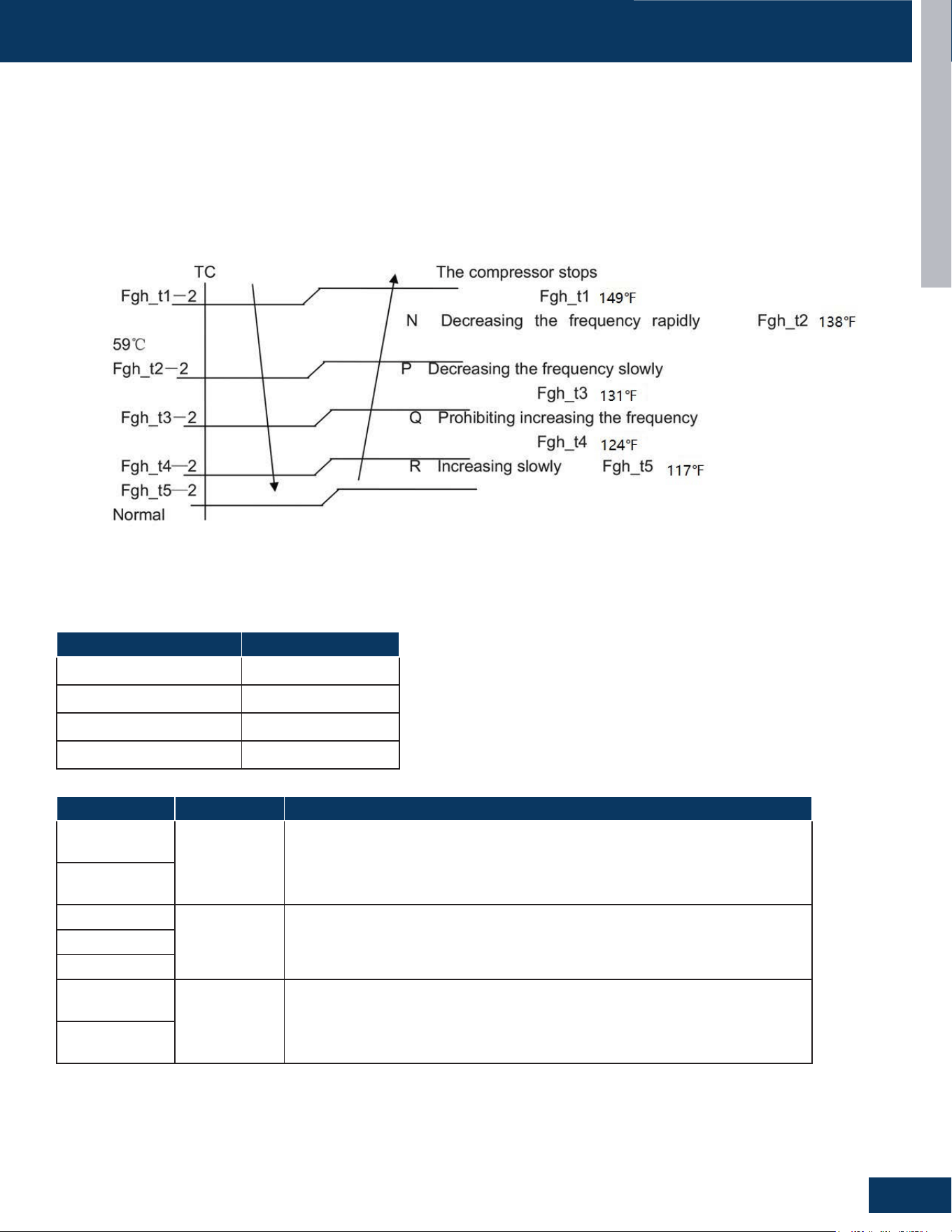
Over-Temperature Heat Mode Indoor Coil
The over-temperature routine will protect the system from excessive high indoor coil temperature during heat mode operation. The system will
be stopped if the indoor coil temperature exceeds 149°F for 2 minutes. The outdoor system may be restarted when the indoor coil temperature
falls below 108°F and the system has been stopped for a minimum of 3 minutes. The error code will be stored in the memory but will not be
displayed.. Conditions that cause high indoor coil temperature include indoor fan failure, dirty indoor coil and operating the system in heat
mode when outdoor air temperatures exceed operating limit. (Too warm outside)
Should this routine be initiated, the system will reduce compressor frequency until the indoor coil temperature reaches 117°F. Once this is
achieved, the system will return to normal operation.
Base Pan Heater Operating Logic and Testing Process
Power supply: 196~254V AC
When the compressor starts in the heating mode, the following conditions will apply:
Outdoor Temperature Pan Heater
>37°F (3°C) OFF
28°F(-2°C) to 34°F (1°C) OFF 20min, ON 10 min
10°F(-12°C) to 25°F (-4°C) OFF 15min, ON 15min
<10°F (-12°C) ON
Model No. Spare Part No. Resistance Value
2G20ED2BEA
0150831548C
1. 220V/180W,(Power range: 162~198W).
2. Cold state withstand voltage: 1500V/min, Hot state withstand voltage: 1200V/min.
3. Coldinsulationresistance:>500MΩ,hotinsulationresistance:>50MΩ.
3G24ED2BEA
2G18AD2BEA
/ /3G24AD2BEA
4G36AD2BEA
4G36ED2BEA
0151045703
1. 220V/180W,(Power range:162~198W).
2. Cold state withstand voltage:1500V/min,hot state withstand voltage: 1200V/min.
3. Coldinsulationresistance:>500MΩ,hotinsulationresistance:>50MΩ.
5G42ED2BEA
INTRODUCTION
A10
ENGLISH
FUNCTIONS AND CONTROL
Compressor Heater Band Operating Logic and Testing
Power supply:196~254VAC
Heater OFF Heater ON
Ta>50°F(10°C)orTd≥68°F(20°C) 100%*60min 0
41°F(5°C)<Ta≤50°F(10°C)andTd<68°F(20°C) 50%*60min 50%*60min
32°F(0°C)<Ta≤41°F(5°C)andTd<68°F(20°C) 33%*60min 66%*60min
Ta≤32°F(0°C)andTd<68°F(20°C) 0 100%*60min
Model No. Spare Part No. Resistance Value
2G20ED2BEA
0150400046A
• Rated voltage:AC220V,Power:27W±7%
• Resistance:1793Ω±7%
3G24ED2BEA
2G18AD2BEA
3G24AD2BEA
4G36AD2BEA
4G36ED2BEA
0010450251
• Rated voltage :AC240V, Power:28W±7%
• Resistance:2057Ω±7%
5G42ED2BEA
Sleep Mode
Sleep mode is set by the controller. After entering sleep mode:
1. Displaylighto(defaultwhenenteringsleepmode,itcanbe
changed through the APP). In sleep mode, when activated from
the controller, the indoor display will be on for 5 seconds, then
switcho.Ifturningothescreenviathelightbutton,the
displaywillturnoafter5seconds(thisisseparatefromthelight
function).
2. Fan speed does not automatically change, but can be set by the
controller (When the user select low fan speed on APP, the unit
will switch to low speed)
3. The buzzer will be silent.
4. The default sleep temperature can be changed by the APP.
During sleep, the user can use the remote controller, wired
controller, centralized controller and APP to change the set
temperature. The next time the unit goes to sleep, it will revert to
the default sleep temperature.
5. Switch the modes to exit sleep mode.
6. Sleep time can be set through the APP.
Enhanced Defrost Mode
Remote control: WiththeODUinheatingmodeoro,setfanspeed
to high, set temperature to 30°C, then press the sleep button 6 times
within 5 seconds. When the unit beeps 3 times, it has entered manual
defrost mode. The method is the same as the heating defrost.
Wired Controller: Enter the defrost mode via the wired controller
interface
Anti-Cold Air Control During Defrosting
IDU will immediately stop the fan after receiving the defrosting signal.
After defrosting, the IDU fan runs according to anti-cold air.
ECO Function
1. Activation
At startup, the ECO function may be activated via the app, or
remote controller or wired controller ECO button. Temperature
compensation is only compensated once upon entry, and the newly
set temperature is no longer compensated during ECO operation.
In cooling mode or heating mode, the user press the ECO button
(or via APP) to enter the ECO mode, and set the temperature 2°F
(or 1°C) higher than the current set temperature (the default is °F
adjustment), which can be adjusted in the APP. The adjusted set
temperature shall not exceed the temperature range below.
2. Functions
ECOfunctionsareeectiveforbothcoolingandheatingmodes.
• After entering ECO mode, the set temperature range of cooling
and heating is 60°F to 86°F, and the operating range of the set
temperature can be reduced through the APP (example: Set
temperature range from 60 °F-86°F to 70°F-80°F). Note: The
maximum set temperature≥the minimum set temperature,and the
displayed set temperature changes together.
• In cooling mode, with ECO mode, when the set temperature
reaches, the user can stop the IDU fan via APP (the ducted will
reach the temperature and stop the air by default, and other IDUs
won’t.
• ThedierentsettingsofECOfunctionswillbestoredintheIDU
memory. The settings remain the same the next time the unit
enters ECO mode.
• Exit ECO mode only by pressing the ECO button or exiting from the
APP.

INTRODUCTION
A11
ENGLISH
FUNCTIONS AND CONTROL
Dry Mode (Dehumidifying Mode)
When Tai>Tset+2°C, the system will operate in cooling mode, with the fan speed controlled according to cooling mode settings when in auto
mode.
WhenTset<Tai≤Tset+2°C,thesystemwillenterDryMode.Thesystemwillrunfor10minuteswiththeindoorunitinlowfanspeed.Afterturning
ofor6minutes,theindoorunitstopsrunning.Onandowillrunalternately.Turnofor6minutesandsendashutdownsignaltotheoutdoor
unit.
WhenTai≤Tset,thesystemwillshutdown.Iftheambienttemperatureislessthan16°C,theindoorfanwillstop,otherwiseitwillcontinueto
run with low speed fan.
Emergency Function (Emergency Power Turn-O Button)
Wired controller: The wired controller comes with an auto-restart function (not separately set).
Remote controller: On/ostatus,mode,fanspeed,temperaturesetting,healthy,swingposition.
Ifthereisatimerorsleepfunction,itwillbeturnedowhenpoweredonagain,andthetimerandsleepwillbecanceled.
Note: Power o and power on, check if there is a wired controller, if the wired controller executes the power-o memory of the wired controller.
Forced Heating/CoolingModes
Dipswitchsetting,cooling60HZ,heating50HZxedfrequencyoperation.
WiFi
For WiFi connections: User makes commission request (turn on the unit, set the unit into cooling mode, fan speed, and 86°F or 30°C,). Code
writes“WiFiServiceRequest_Connect”toERDErd_RequestWiState.
Turn o WiFi module: Press and hold the WiFi button for at least 3 seconds. If the WiFi module is in AP mode, connecting, reconnecting,
scanning,connectedbutO,orconnected,asinglepressoftheWiFibuttonwillbeignored.OnlyiftheWiFibuttonispressedandheldforat
least3secondswilltheWiFimoduleenteromode.
Setting Temperature Compensation
Via Remote Controller:
Cooling mode: Presstheon/obuttonandpoweronincoolingmode.Usethesettemperatureof24°Casthereferencepoint,andpressthe
swing button (or sleep button) 7 times within 5 seconds. The indoor unit will beep twice, indicating it is now in compensation setting mode.
At this time, adjusting the temperature point to 23°C will set temperature compensation to -1°C. Adjusting the temperature point to 22°C
willsettemperaturecompensationto-2°C,andsoon.Maximumcompensationis-8°C(16°C).Powerotosetcompensation.Tocancel
compensation, repeat the above and set the temperature point back to 24°C.
Heating mode: Press the swing button (or sleep button) 7 times within 5 seconds. The indoor unit will beep twice, indicating it is now in
compensation setting mode. Select heating mode via the controller, then press temperature key to select set temperature and compensation
temperature (current set temperature -24 °C. That is, at 24°C the compensation temperature is 0 degrees, and 25 . After 25°C means -1°of
compensationtemperature.Afterthesettingiscompleted,turnothecontroller.Theindoorunitwillbeepfourtimestoindicateithasexited
temperature compensation setting mode. The compensated temperature is stored in EE, and it will carried out according to power failure
compensation.
Via Wired Controller:
Set according to the temperature compensation method of the wired controller.

[This page left intentionally blank]

OUTDOOR UNITS
B1
ENGLISH
OUTDOOR UNITS
TABLE OF CONTENTS
2G20ED2BEA
3G24ED2BEA
4G36ED2BEA
5G42ED2BEA
2G18AD2BEA
3G24AD2BEA
4G36AD2BEA
COMPONENTS .......................................................................................................................................................................B2
Component Overview ...........................................................................................................................................................B2
PCB Overview .........................................................................................................................................................................B4
Main Control Board 12V ...........................................................................................................................................B5
Main Control Board 5V .............................................................................................................................................B5
Inverter Board 15V ...................................................................................................................................................B6
Inverter Board 3.3V ..................................................................................................................................................B6
Fan Motor ..................................................................................................................................................................B7
Compressor ..............................................................................................................................................................B7
Four Way Valve .......................................................................................................................................................... B7
Crankcase Heater .....................................................................................................................................................B7
Chassis Heater .........................................................................................................................................................B8
SV ..............................................................................................................................................................................B8
Electronic Expansion Valve (EEV) ............................................................................................................................B8
0151801003 ..............................................................................................................................................................B9
0150406834H .........................................................................................................................................................B10
OPERATION ..........................................................................................................................................................................B11
Cooling Mode .......................................................................................................................................................................B11
Heating Mode .......................................................................................................................................................................B12
Defrost Cycle ........................................................................................................................................................................B13
Electronic Expansion Valve (EEV) Control ........................................................................................................................... B14
4-Way Valve Heating Control ............................................................................................................................................... B14
Compressor Sump Heater ...................................................................................................................................................B14
Defrost Control.....................................................................................................................................................................B15
Discharge Sensor Protection ............................................................................................................................................... B15
High Current Protection .......................................................................................................................................................B15
High Pressure Protection .....................................................................................................................................................B16
High Pressure Protection in Heating ...................................................................................................................................B16
Low Pressure Protection ......................................................................................................................................................B16
Oil Return Cycle ....................................................................................................................................................................B17
Oil Return in Cooling Mode ...................................................................................................................................................B17
Oil Return in Heating Mode ..................................................................................................................................................B18
Correction Ratio of Capacity According to the Length of Piping ....................................................................................... B19
SERVICE PROCEDURES ........................................................................................................................................................B20
Outdoor Fan Motor ...............................................................................................................................................................B20
Fault Detection Methods for DC Motors .............................................................................................................................B20
Temperature Sensor .............................................................................................................................................................B20
4-Way Valve ...........................................................................................................................................................................B21
Electronic Expansion Valve (EEV) ........................................................................................................................................B21
Leak Test ...............................................................................................................................................................................B22
System Evacuation ...............................................................................................................................................................B22
Refrigerant Charging ............................................................................................................................................................B23
DIMENSION DRAWINGS .......................................................................................................................................................B24
PIPING DIAGRAMS ................................................................................................................................................................ B28
WIRING DIAGRAMS ............................................................................................................................................................... B33
OUTDOOR/INDOOR WIRING CONNECTIONS ...................................................................................................................... B38
OUTDOOR UNITS
B2
ENGLISH
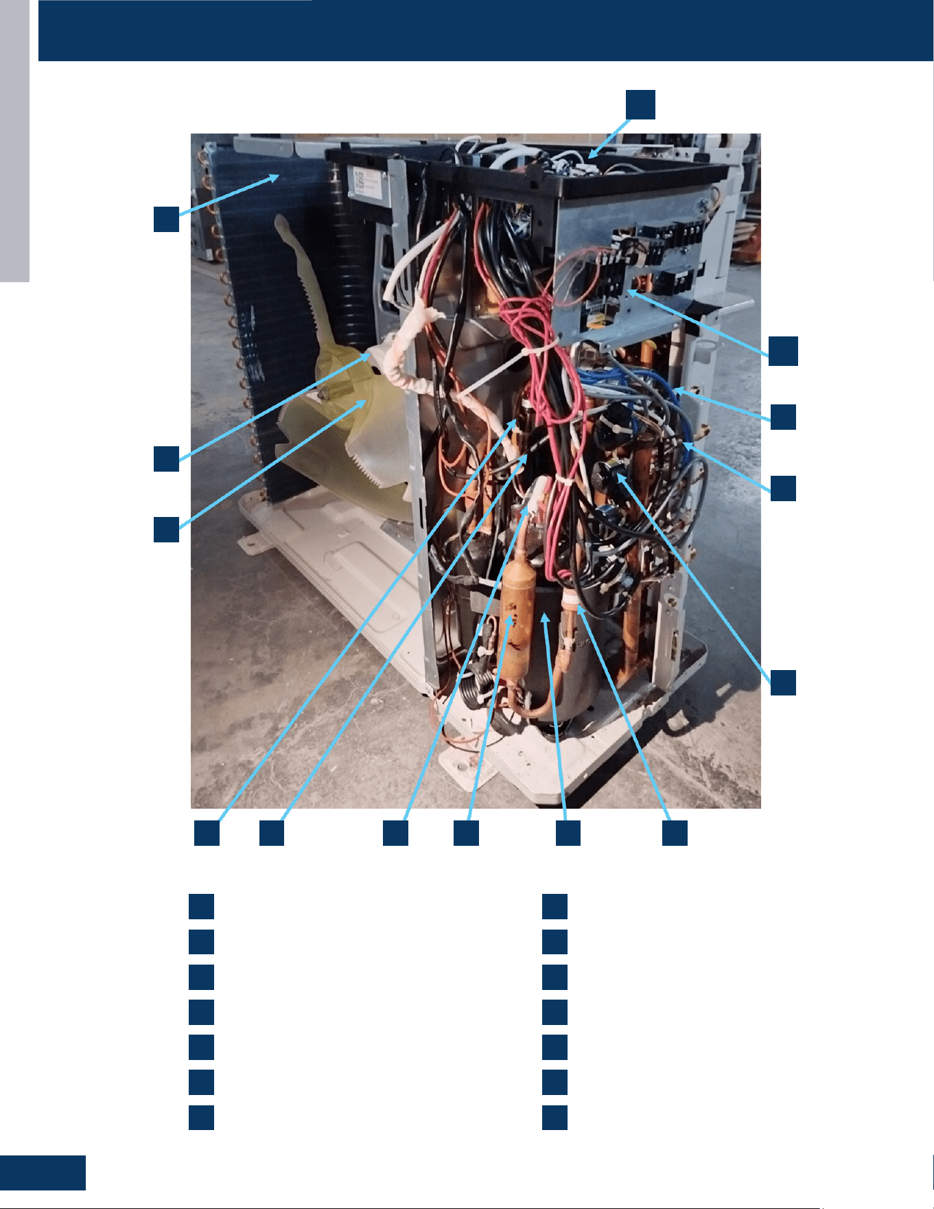
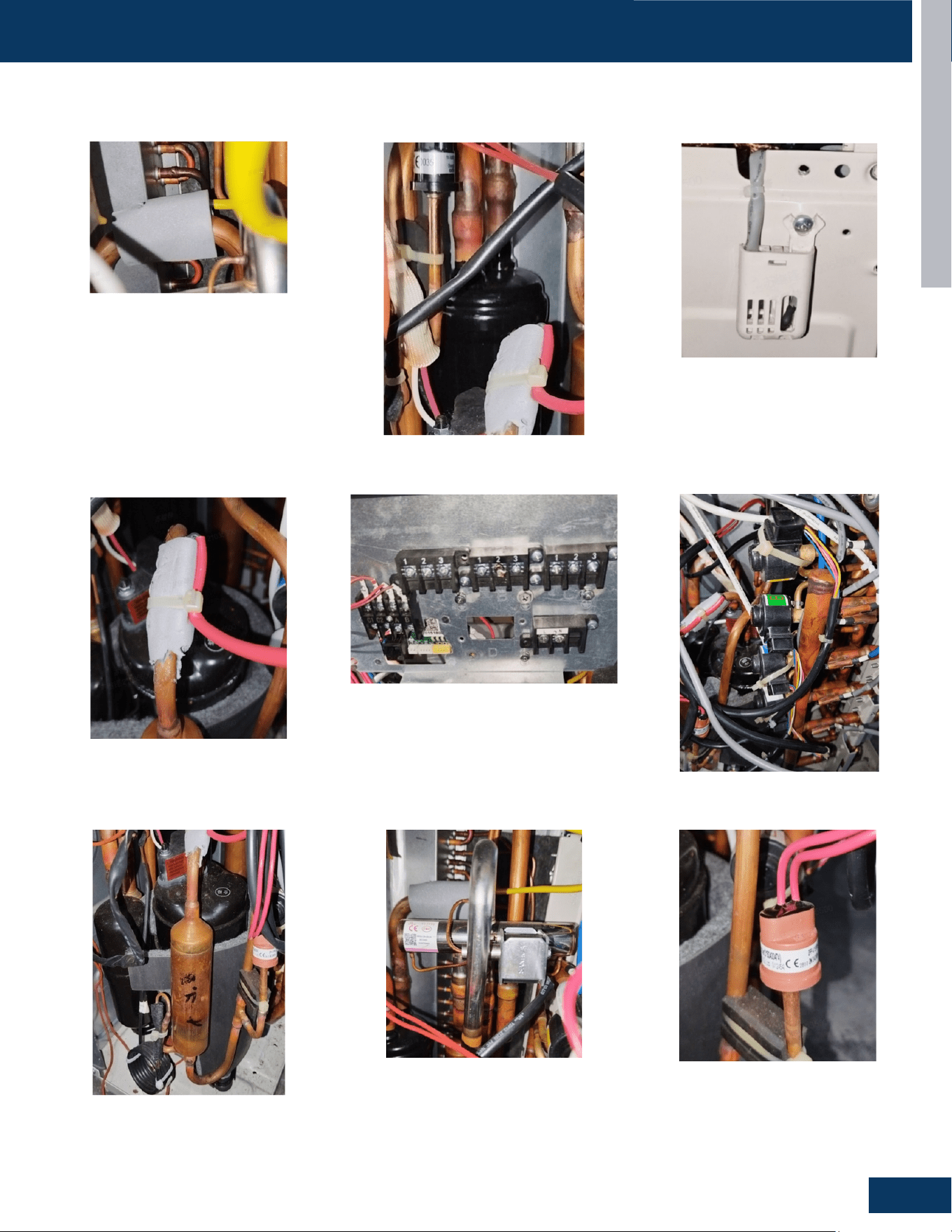
Component Overview
COMPONENTS
PCB and Module Board
Terminal Block
Liquid Temperature
Gas Temperature
EEV
High Pressure Switch
Compressor
1
2
3
4
5
67891011
1 8
2 9
3 10
4 11
5 12
6 13
7 14
13
14
12
Silencer
Td
Gas-Liquid Separator
Low Pressure Switch
Fan
Motor
Condenser
OUTDOOR UNITS
B3
ENGLISH
COMPONENTS
Suction Temperature Sensor
Gas-Liquid Separator
Ambient Temperature Sensor
Compressor & Silencer 4-Way Valve High Pressure Switch
Discharge Temperature Sensor Terminal Block EEV Assembly
OUTDOOR UNITS
B4
ENGLISH
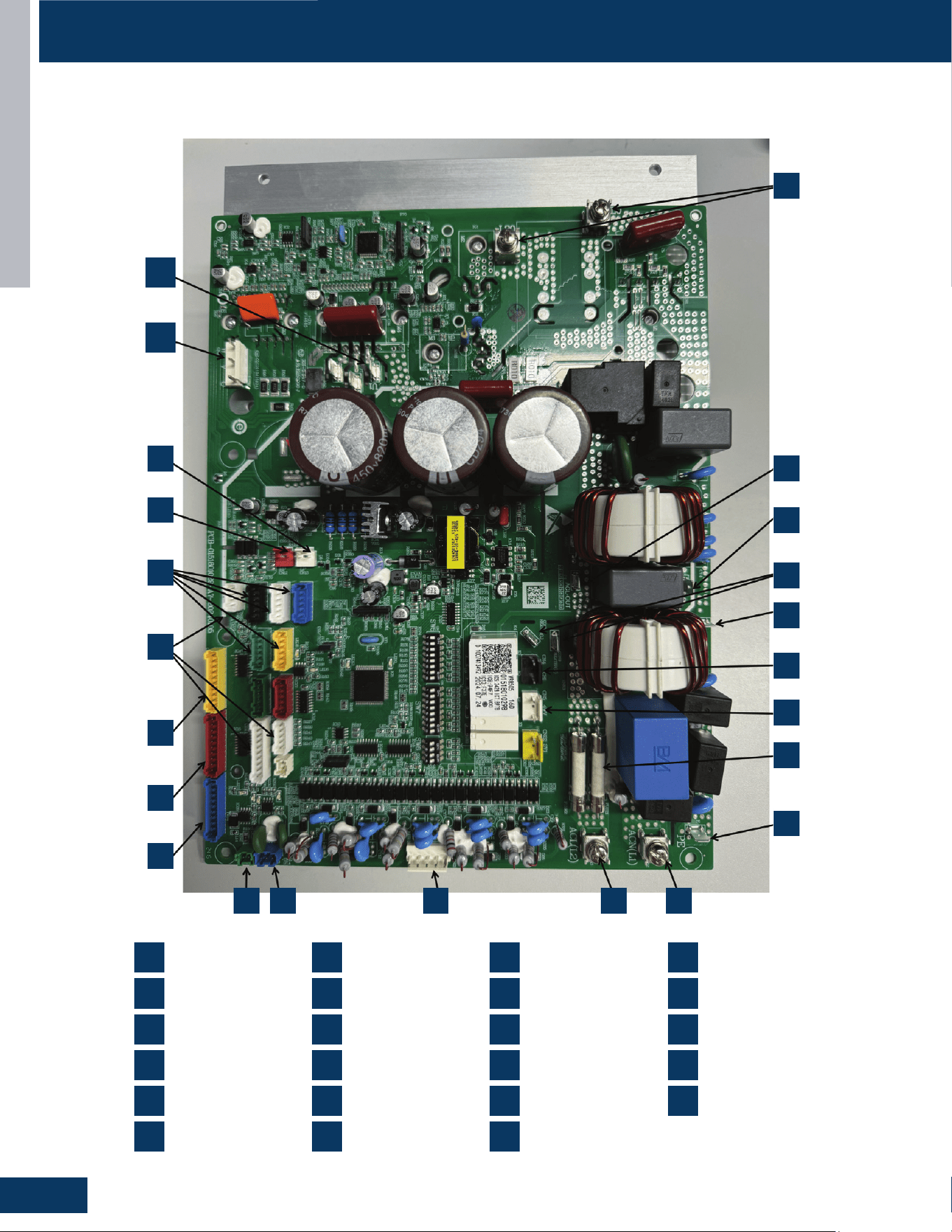
COMPONENTS
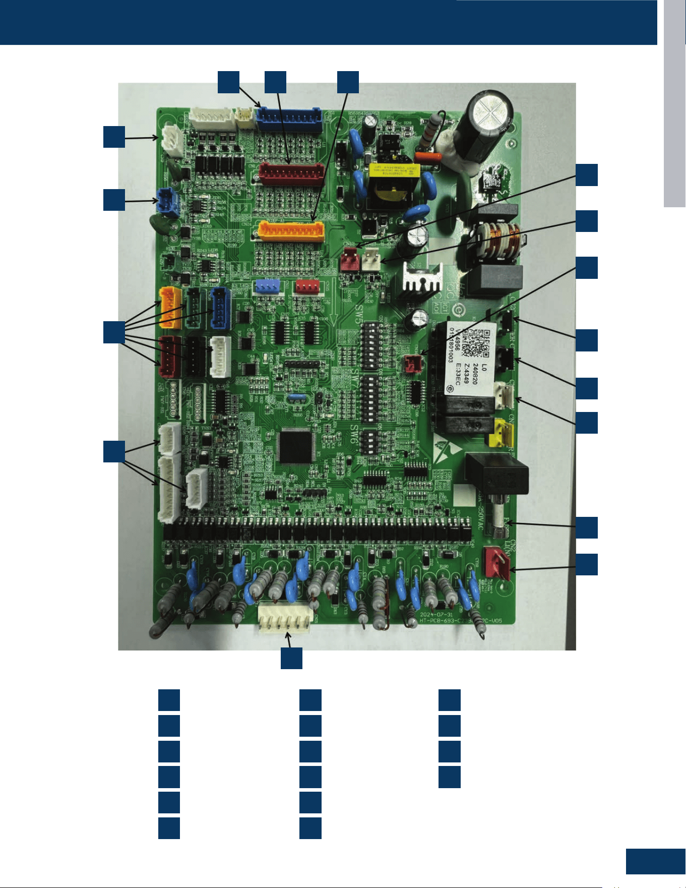
PCB Overview
0151801029/0151801029B
1
2
3
4
5
6
7
8
9
10 11 12 13 14
15
16
17
18
19
20
21
22
23
CN60
CON8 CON9
P5
P4
Reactor Terminal
19
20
21
22
23
U1V1W1
CN41
CN13
CN12
CN16-CN20
CN26 CN23 CN8
1
2
3
4
5
6
CN24
CN1
CN14
CN29
CN10 OTA
CN21
7
8
9
10
11
12
CN53
CN52
PE
FUSE1 FUSE2
CN5
CN4
13
14
15
16
17
18
OUTDOOR UNITS
B5
ENGLISH
COMPONENTS
↓
12VDC
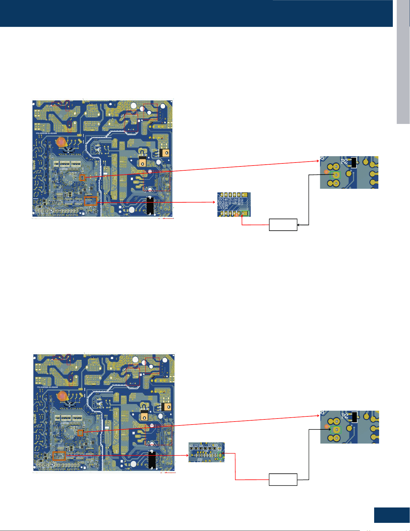
Main Control Board 12V
• TheinputvoltageofrelayK1,K2,K3,K4,K5,K6aectstheelectricaloutputoftheelectricheater,chassisheater,fourwayvalveandSV.
• TheinputvoltageoftheelectronicexpansionvalveandIC9,IC10,IC11,IC12aectstheoutputoftheelectronicexpansionvalveCN2,CN3,
CN16, CN17, CN18, CN19, and CN20.
• RelayRYinputvoltageaectstherelayPTCsuctionandthereisariskofPTCburn.
• TheinputvoltageoftheIC19aectsthe5Vvoltageoutput.
↓
5VDC
Main Control Board 5V
• TheinputvoltageofthemainchipIC18andEEchipIC13willaectthenormaloperationoftheIC18andIC13,andsomeprogramsinmain
control board cannot be started or reset normally.
• TheinputvoltageofthedipswitchloopaectsthefunctionselectionoftheDIPswitch.
• TheoptocouplerandthesignalvoltageofthetriodebetweenODUandIDUaectthecommunicationbetweenODUandIDU.
• Thesignalvoltageofthemodulecommunicationloopaectsthecommunicationbetweenthemaincontrolboardandtheinverterboard.
• ItaectshighandlowpressureCN13,CN12
• Itaectstheuseofdisplayboardsandmonitors.
• ItaectsthecircuitsofthePCBsensorsCN7,lCN1,CN14andCN24.
OUTDOOR UNITS
B6
ENGLISH
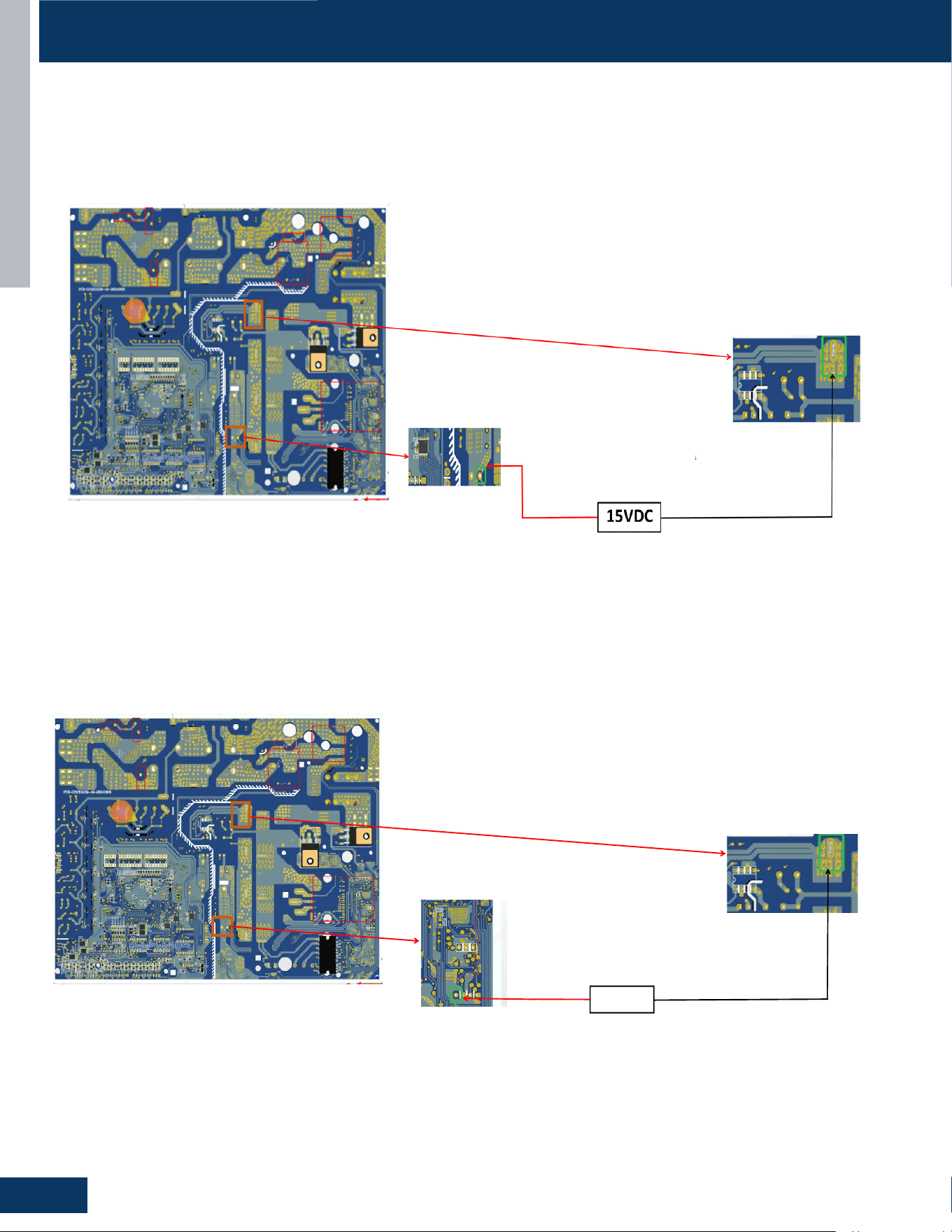
Inverter Board 15V
• TheinputvoltageoftheIC20aectsthe3.3VoutputofthePBC
• TheIPM2inputvoltageaectstheoutputoftheDCfanCN41
• TheinputvoltageofIPM1aectstheoutputofthecompressor
• TheinputvoltageofIC3aectsthenormaluseofIGBTandIG1.ItalsoaectstheoperationofPFCcircuit.
↓
3.3VDC
Inverter Board 3.3V
• Theinverterboard’smainchipIC5andEEIC7inputvoltageaectsthenormaloperationoftheIC5andIC7.Someprogramsinmaincontrol
board cannot be started or reset properly.
• Itaectsmodulecommunicationwiththemaincontrolboard.
• TheinputvoltageofIC1,IC4,IC2,IC6andIC48aectsthePFCboostingcircuit,fanoutput,andpressoutput.
COMPONENTS
OUTDOOR UNITS
B7
ENGLISH
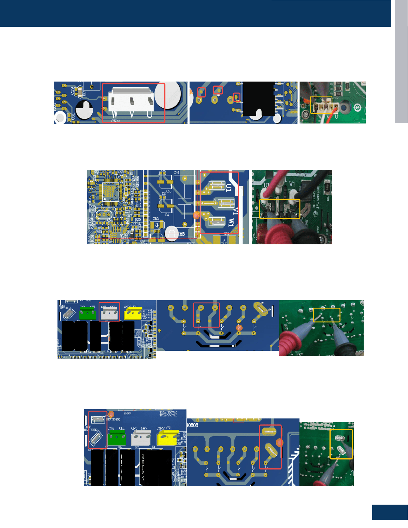
Fan Motor
• The fan is three-phase U, V, and W, and the current between each phase is about 1A.
• Multimeter DC current range tests the current between any two phases.
• The fan motor is tested at about 16V DC.
Compressor
• The compressor is three-phase U V W, and the current between each phase is about 1A in the no-load state of the compressor. Multimeter
DC current range Tests the current between any two phases. (The copper foil tinning on the front of the compressor port can be tested)
Back Test Point
Compressor Port
Four Way Valve Terminal
Crankcase Heater Terminal
Four Way Valve
• In the case of relay suction, if the output voltage of the test port is 0V (AC), it means that the four way valve is abnormal.
• If it is 220V (AC) -15%~+10%, it means normal.
COMPONENTS
Fan Motor Terminal
Back Test Point
Back Test Point
Crankcase Heater
• In the case of relay suction, if the output voltage of the test port is 0V (AC), it means that the crankcase heater is abnormal; if it is 220V (AC), it
means normal.
OUTDOOR UNITS
B8
ENGLISH
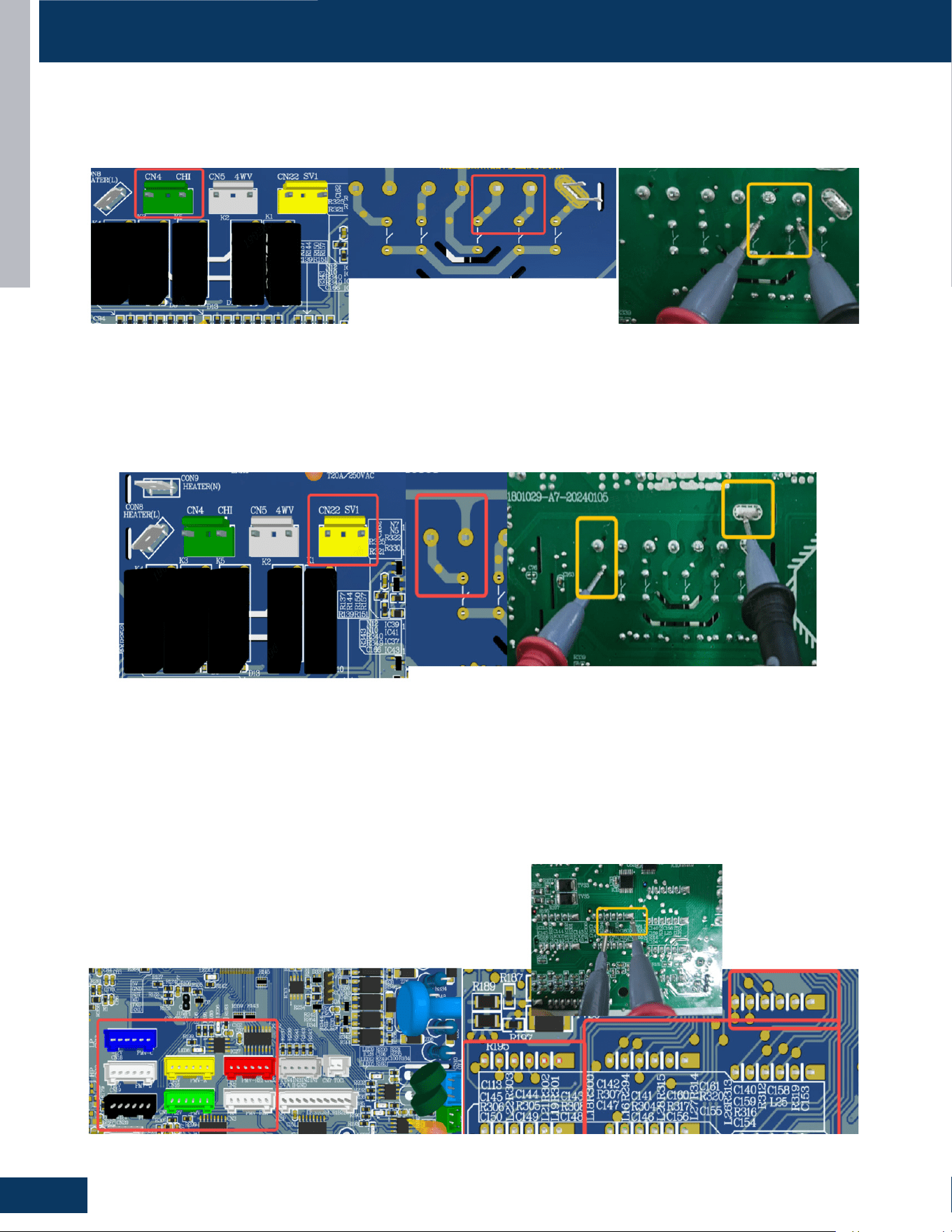
Chassis Heater
• In the case of relay suction, if the output voltage of the test port is 0VAC, it means that the chassis heater is abnormal. If it is 220VAC, it
means normal.
SV
• In the case of relay suction, if the output voltage of the test port is 0VAC, it means that the chassis heater is abnormal. If it is 220VAC, it
means normal.
Electronic Expansion Valve (EEV)
• Measure the voltage between the electronic expansion valve output pin and 12V. If the voltage is 0V (DC), it means that the
electronic expansion valve is abnormal.
• If the voltage is 12V (actually lower than 12V), it means normal.
• (The electronic expansion valve actually has four outputs at each port, and all outputs need to be tested).
Chassis Heater Terminal
SV Terminal
EEV Terminals
Back Test Point
Back Test Point
Back Test Points
COMPONENTS
OUTDOOR UNITS
B9
ENGLISH
COMPONENTS
1
2
3
4
5
6
7
8
9
10
11
12
13
16 15 14
0151801003
CN12
CN24
CN1
CN14
13
14
15
16
CN9
CN10
CN3 CN16-20
CN8 CN23 CN26
CN21
CN2
1
2
3
4
5
6
FUSE1 FUSE2
CN5
CN4
CN28
CN34
CN13
7
8
9
10
11
12
OUTDOOR UNITS
B10
ENGLISH
COMPONENTS
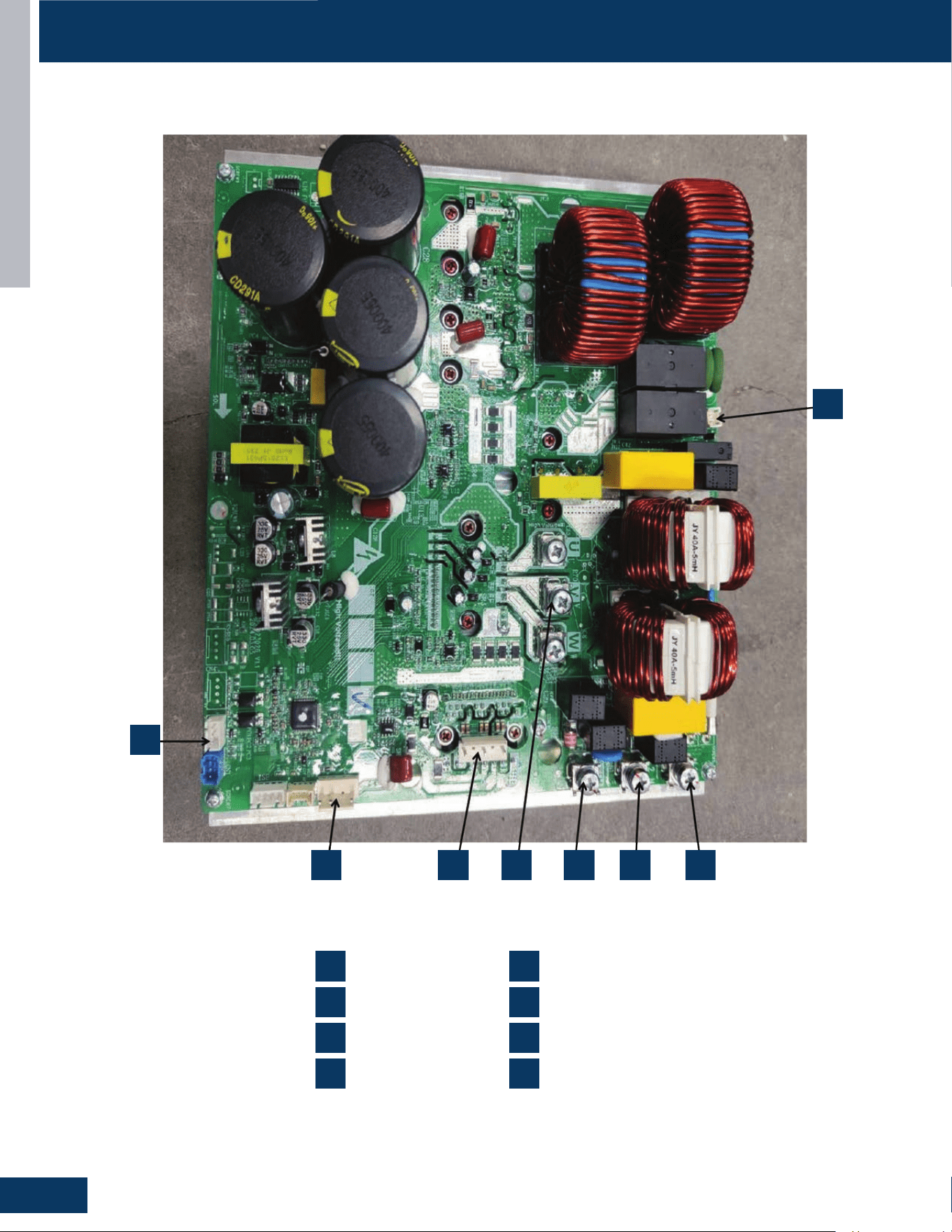
1
2 3 4 5 6 7
8
0150406834H
1
2
3
4
CN1
CN7
DCFAN1
U1V1W1
5
6
7
8
EARTH
L1
L2
CN2
OUTDOOR UNITS
B11
ENGLISH
OPERATION
On a call for cooling, the indoor unit will send the room temperature and set-point requirement to the outdoor unit PCB via the data signal wire
path. The indoor louvers will open and the indoor fan motor will start.
TheoutdoorunitwillenergizetheEEVsthatarecontrollingrefrigerantowtothecallingindoorunits.ThepositionoftheEEVswillbesettoan
initial position based upon the outdoor air temperature.
The 4-way valve is de-energized. After a 3-minute time delay, the outdoor fan motor will be energized. Shortly after the outdoor fan motor
turns on, the compressor will start in low frequency. Picture of Service board showing compressor frequency.
1
1
2
2
3
3
4
4
5
5
6
6
Service board
showing the
frequency
Cooling Mode
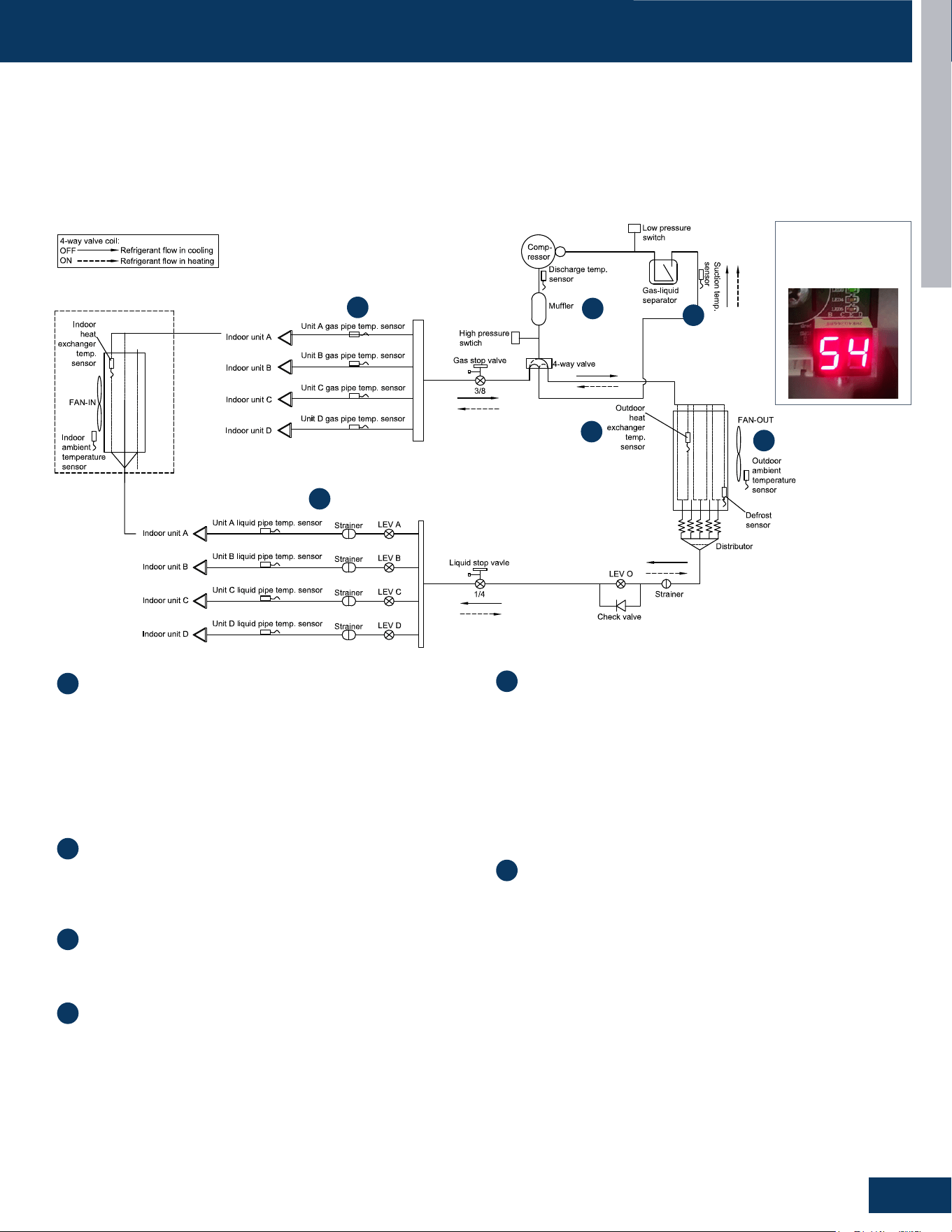
Discharge Temperature Sensor (Td): The temperature of
the compressor discharge hot gas will be monitored by the
Discharge Temperature Sensor. If the sensor reads too hot or
cool, the frequency/status of the operation will be adjusted
accordingly.
The hot gas will leave the oil separator and enter the 4-way
valve, which directs the hot gas to the outdoor coil. The
refrigerant will condense in the outdoor coil and be subcooled.
The refrigerant is now in a liquid state.
Outdoor Heat Exchanger (Coil) Temperature Sensor (Tc):
This sensor monitors the temperature of the outdoor coil during
condensing operation. If abnormal condensing temperature
is detected, the outdoor fan motor speed or compressor
frequency may be adjusted.
Outdoor Ambient Temperature Sensor (Ta): The outdoor air
temperature will be monitored by the PCB. If the outdoor air
temperature rises or falls, the speed of the outdoor fan may be
changed.
Liquid Pipe Temperature Sensor (Tc2): The Liquid Pipe Sensor
will monitor the temperature of the refrigerant leaving the EEV.
The low pressure low temperature refrigerant will enter the
mixed phase liquid line and travel to the indoor unit. Heat from
the indoor air passing across the evaporator coil will transfer to
the cold refrigerant, sending cool air into the space and changing
the liquid refrigerant into a cool vapor.
The cold vapor will travel down the vapor line and return to the
outdoor unit via a path through the gas stop valve.
Gas Pipe Temperature Sensor (Tc1): The Gas Pipe Sensor
will monitor the temperature of the gas pipe to calculate the
dierencebetweenLiquidPipeTemperatureandGasPipe
Temperature. If a change in EEV port opening size is needed, the
EEV will make a small adjustment.
The vaporized refrigerant enters the 4-way valve and travels to
the vapor line accumulator. The accumulator will trap any liquid
refrigerant if present to prevent it from entering the compressor.
The vapor will exit the accumulator and enter the compressor.
This cycle will repeat until the demand for cooling ends.
Suction Temperature Sensor (Ts): The temperature of the
suction gas entering the compressor is monitored by the
Suction Temperature Sensor. Before stopping operation, the
EEV may open to feed more refrigerant or close to warm up the
line.
The demand becomes less as the indoor temperature drops
toward the desired temperature, so the compressor will reduce
speed. When the set temperature is reached, the compressor
andoutdoorfanwillshuto.Thecirculatingfanofeachindoor
unit continues to run.
OUTDOOR UNITS
B12
ENGLISH
OPERATION
High Pressure Swtich
Four Way Valve
4WV
Low Pressure Switch
LP
Gas Stop Valve
with
Service Port
Ø
15.88mm
(
5/8in.
)
Sensor
TC
FAN-OUT
Sensor
TA
Sensor
TE
Distributor
Liquid Stop Vavle
with
Service Port
Ø
9.52mm
(
3/8in.
)
PMV
B
Indoor Unit B
Sensor TC1
Sensor TC1
Indoor unit A
Indoor unit B
FAN-IN
Sensor
TAi
Sensor
TM
PMV
A
Indoor Unit A
High temperature,high pressure,gas
High temperature,high pressure,liquid
Low temperature,low pressure,gas/liquid
Liquid Pipe
Gas Pipe
Sensor
TC2
Sensor
TC2
Sensor
TS
LPS
HPS
Heat
Exchanger
Heat
Exchanger
Electronic Expansion Valve
Electrionc Expansion Valve
Filter
Filter
Filter
Compressor
INV
Sensor
TD
Silencer
HP
Single Way Valve
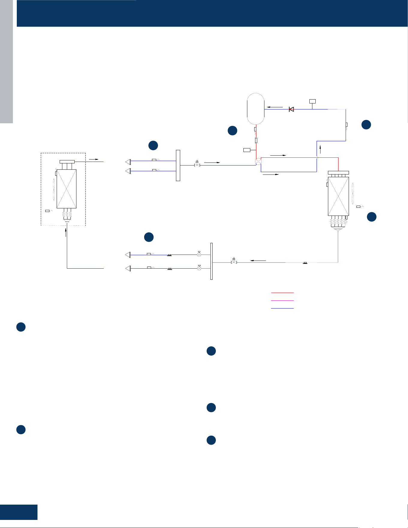
On a call for heating, the indoor unit will send the room temperature and set-point requirement to the outdoor unit PCB via the data signal wire
path.Theindoorunitlouverswillopen.Thefanwillnotstartuntilthecoilhaswarmedsucientlytoavoidcolddrafts.
The 4-way valve will energize and the outdoor fan will start. The compressor starts at a slow speed and will increase based upon demand. The
indoor fan starts after the indoor coil is warm enough to avoid circulating cool air.
Withthecompressoroperating,refrigerantwillbegintoowthroughouttherefrigerationcircuit.Theoperatingfrequencyofthecompressor
will be displayed on the Service Monitor Board.
Heating Mode
1
2
3
4
5
Discharge Temperature Sensor (Td): The temperature of
the compressor discharge hot gas will be monitored by the
Discharge Temperature Sensor. If the sensor reads too hot or
cool, the frequency/status of the operation will be adjusted as
needed.
The hot gas will leave the oil separator and enter the 4-way
valve. The 4-way valve will direct the hot gas to ALL of the
indoor coils.
Note: Any indoor unit that is in heating mode will have it’s louver
open and indoor fan running. Non-calling indoor units will receive
hot gas but their fans will remain on very low speed with the louver
open. When demand for heat increases, the indoor fan will speed
up to meet the increased demand.
Gas Pipe Temperature Sensor (Tc1) & Indoor Heat Exchanger
Temperature Sensor (Toci): The temperature of Tc1 should now
be hot. This will indicate the 4-way valve is directing hot gas to
theindoorcoils.ThePCBwilldetectthetemperaturedierence
and generate an Error Code.
The indoor heat exchanger temperature sensor will monitor
the temperature of the indoor coil to ensure it is hot enough to
prevent blowing cold air. Once adequately warm temperature is
sensed at the indoor coil, the PCB will increase the fan speed if
needed to meet the demand.
The hot gas entering the indoor coil will condense into a
saturated mix and then be subcooled. The refrigerant will return
to the outdoor unit via the liquid line.
Liquid Pipe Temperature Sensor (Tc2): This sensor monitors
the temperature of the refrigerant liquid returning from the
indoor coil. The indoor EEV opening angle is adjusted according
to the degree of superheat.
As the outdoor coil absorbs heat from the surrounding air, the
very cold liquid refrigerant is changed to a cool vapor. This vapor
travels through the 4-way valve to the accumulator.
Defrost Temperature Sensor (Te): The outdoor coil
temperature will be sensed by the Defrost Sensor. The sensor
will use this temperature to adjust EEV open angle and to
calculate when a defrost cycle is necessary.
Suction Temperature Sensor (Ts): The temperature of the
suction gas entering the compressor is monitored by the
Suction Temperature Sensor.
As the demand becomes less while the indoor temperature rises
toward the desired temperature, the compressor will reduce
speed. When the set temperature is reached, the compressor
andoutdoorfanwillshuto.Thecirculatingfanofeachindoor
unit continues to run.
1
2
3
4
5
OUTDOOR UNITS
B13
ENGLISH
OPERATION
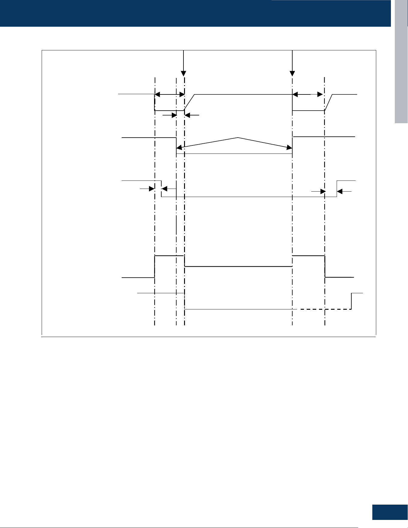
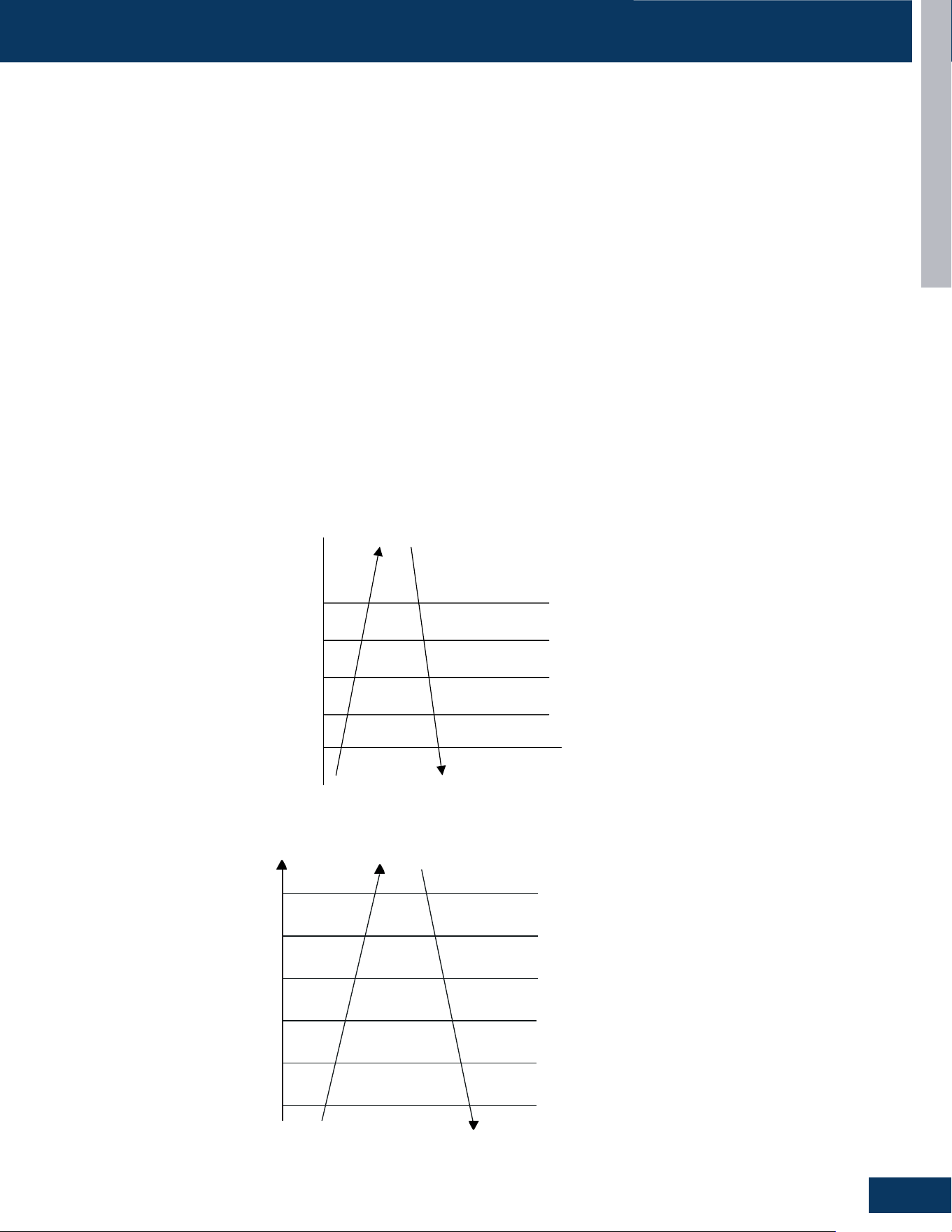
Beginning end
Fixed frequency Indicated FQY 60s Defrosting FQY A(E) 60s Soft startup
Compressor
0HZ
0HZ
5s
Outdoor motor ON Send defrosting signal to indoor Auto
OFF
4-way valve ON
OFF
50s
450-pulse 450-pulse
300-pulse(E)
All EEVs Auto open angle Auto open angle
All indoor motors ON
OFF
Anti-cold air function
Multi:
5s
Defrost Cycle
OUTDOOR UNITS
B14
ENGLISH
Electronic Expansion Valve (EEV) Control
Electronic characteristics
Max. open angle 480 pulses
Open angle limitation of EEV
Unit stop Max. open angle Thermostat OFF Min. open angle
Cool/ dry 5 pulses 470 pulses 5 pulses 80 pulses
Heat 50 pulses 470 pulses 50 pulses 80 pulses
The EEV routinely opens and closes to maintain the compressor discharge temperature within an acceptable range.
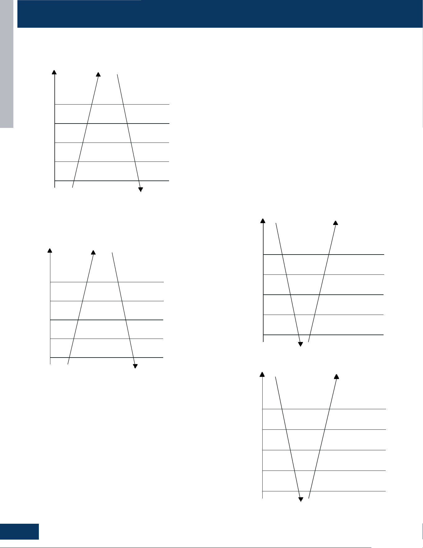
compressor ON
OFF
4-way valve ON
OFF
50S
2 minutes and 55s
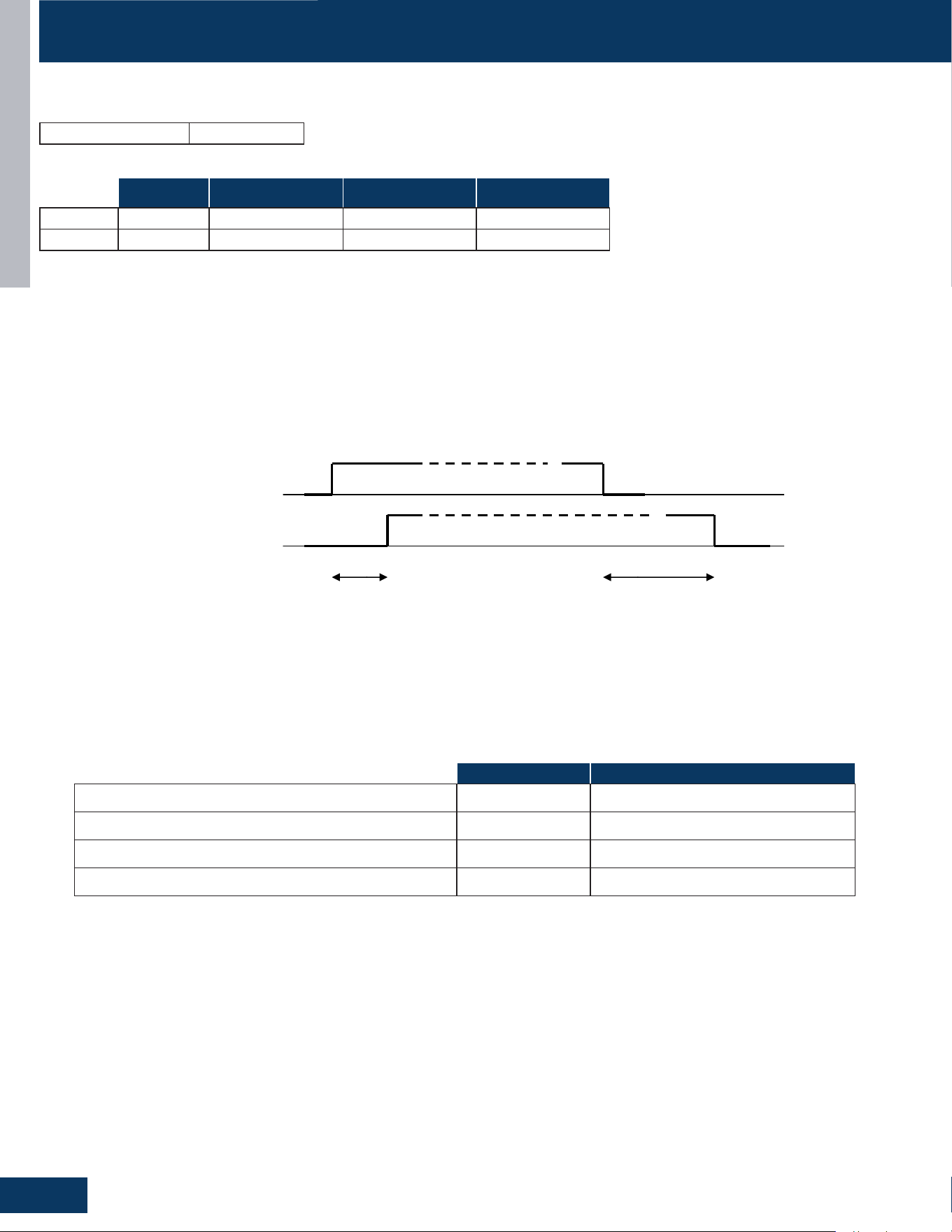
4-Way Valve Heating Control
Whenthecompressorstartsintheheatingmode,thereisa1-minutedelaybeforepowerisappliedtothe4-wayvalvetoswitchtheowofhot
refrigeranttotheindoorcoil.Whenthecallforheatissatisedandthecompressorshutso,a3-minutedelaywilloccurbeforethe4-wayvalve
is powered down and switches back to the at-rest (cooling) position.
If the 4-way valve does not switch into the heating mode, after 15 minutes of compressor run time and the indoor coil temperature is below
41°F/5°C,thecompressorwillstopandtheunitwilldisplaya17-asherrorcodeontheoutdoorPCB.
Compressor Sump Heater
The sump (crankcase) heater keeps refrigerant at a higher temperature than the coldest part of the system. This prevents refrigerant from
mixing with the compressor oil and also dries condensed refrigerant inside the sump. The sump heater will be energized when the ambient
temperatureisbelow81°F/27°Candwillbeowhentheambientis90°F/32°C.
Heater OFF Heater ON*min
Ta>50
O
F(10
O
C) OR Td>=68
O
F(20
O
C) 100%*60min 0
41
O
F(5
O
C<Ta≤50
O
F(10
O
C)and Td<68
O
F(20
O
C) 50%*60min 50%*60min
32
O
F(0
O
C)<Ta≤41
O
F(5
O
C)and Td<68
O
F(20
O
C) 33%*60min 66%*60min
32
O
F(0
O
C)>=Ta and Td<68
O
F(20
O
C) 0 100%*60min
OPERATION
OUTDOOR UNITS
B15
ENGLISH
Defrost Control
In the heating mode and along with the ambient sensor, the defrost sensor monitors the temperature of the outdoor coil to determine if
defrostisneeded.Ifthecompressorhasbeenrunningfor10minutescontinuouslyandfor45minutesoverall,thedierencebetweenthe
ambient sensor (Ta) and the defrost sensor (Te) will be checked. The system will initiate the defrost cycle if the following conditions can be
met for 5 continuous minutes:
Te≤CxTa-A
Te: Defrost temperature sensor
Ta: Ambient temperature
C:IfTa<32°F/0°CthenC=0.80,IfTa≥32°F/0°CthenC=0.60
A: 8, moderate climate (factory setting) 6, severe climate (alternate setting)
End defrosting: If the defrost sensor (Te) detects the temperature of the outdoor coil is above 44°F (7°C) for 60 seconds or is above 54°F
(12°C) for 30 seconds, the defrost cycle will terminate. If these temperatures cannot be reached, the defrost cycle will automatically
terminate in 10 minutes.
Timed Defrost Option (SW1-4 ON): When the outdoor ambient temperature sensor (Ta) detects temperature less than 32°F (0°C), In
heating mode, if the compressor runs continuously for 60 minutes or cumulatively for 240 minutes the system will defrost. Defrosting
frequency is 68 HZ, with a defrosting time of 60 minutes.
OPERATION
Discharge Sensor Protection
If the discharge temperature is higher than normal, the compressor will slow down to lower the temperature.
Discharging t
emp.
Td
Reduce FQY rapidly 2HZ/S
Reduce FQY rapidly 1HZ/S
Reduce FQY slowly 1HZ/10S
Remain FQY
Increase FQY slowly 1HZ/10S
118℃
115℃
112℃
109℃
105℃
95℃
Unitary:
Multi:
Discharging temp. Td
Reduce FQY rapidly 1HZ/S
Reduce FQY slowly 1HZ/10S
Remain FQY
Increase FQY slowly 1HZ/10S
If keeping for 10s, the unit stops, 3 minutes later, the unit can
re-startup. If in 60 minutesthe unit occurs alarm for 3 times, the
failure can be eliminated.
Remain FQY
If the discharge temperature sensor reaches 243F for 10
seconds, the compressor will shut off. After the 3-minute
time delay, the compressor will restart. If this occurs
three times in a 60-minute period, the compressor will
lock out. Until the cause of the high temperature is
discovered, the compressor will not restart until the
power is interrupted then restored.
203℉( 95℃)
207℉( 97℃)
225℉( 107℃)
234℉( 112℃)
243℉( 117℃)
If the temperature reaches 150
O
F(66
O
C) three
times in one hour, the system will lock out. Reset by
turningpoweroandbackon.
Reduce FQY rapidly 2Hz/S
Reduce FQY rapidly 1Hz/S
Reduce FQY rapidly 1Hz/10S
Remain FQY
Reduce FQY slowly 1Hz/S
100%*I
98%*I
96%*I
96%*I
90%*I
88%*I
Remain FQY
High Current Protection
The below table is the outdoor unit protection current and compressor current.
OUTDOOR UNITS
B16
ENGLISH
High Pressure Protection in Cooling
If there is an abnormal stop
3 times in 1 hour, the unit
willturno.Turnoand
restore power to clear error.
Reduce FQY rapidly 2Hz/S
Reduce FQY slowly 1Hz/S
Remain FQY
Raise FQY slowly 1Hz/10S
131
O
F(55
O
C)
Tc--cooling
138
O
F(59
O
C)
144
O
F(62
O
C)
147
O
F(64
O
C)
150
O
F(66
O
C)
Remain FQY
High Pressure Protection In Heating
If the temperature reaches
158
O
F(70
O
C) three times in
one hour, the system will lock
out. Reset by turning power
oandbackon.
Reduce FQY rapidly 2Hz/S
Reduce FQY slowly 1Hz/10S
Remain FQY
Raise FQY slowly 1Hz/10S
129
O
F(54
O
C)
Tc--heating
135
O
F(57
O
C)
138
O
F(59
O
C)
145
O
F(63
O
C)
158
O
F(70
O
C)
Remain FQY
High Pressure Protection
Low Pressure Protection
With the compressor running, if the low pressure switch opens for 1
minute, the compressor will stop.
If this condition occurs 3 times in an hour, the compressor will lock
out and a low pressure error code will be displayed at the indoor unit.
If the compressor is not running and the switch opens for 30 seconds,
a low pressure error code will be displayed.
The low pressure switch does not stop compressor operation or
signal an error code during the following conditions:
• Therst8minutesofruntimewhenthecompressorstartsanew
cycle
• During defrost
• When the ambient temperature is below 32°F/0°C
• Following the termination of an oil return cycle
When any of the above 4 conditions are present, low pressure
protection is provided by the coil temperature sensors in both
heating (Te) and cooling (Tc2) modes.
Operate normally
Min. running FQY 20Hz
LP OFF & FQY 20Hz
LP ON & FQY 20Hz
Raise FQY slowly 1Hz/10S
-49
O
F(-45
O
C)
Tc2
-40
O
F(-40
O
C)
-31
O
F(-35
O
C)
-22
O
F(-30
O
C)
-13
O
F(-25
O
C)
Low Pressure Protection in Heating Mode:
Operate normally
Min. running FQY 20Hz
LP OFF & FQY 20Hz
LP ON & FQY 20Hz
Raise FQY slowly 1Hz/10S
-49
O
F(-45
O
C)
Te
-40
O
F(-40
O
C)
-31
O
F(-35
O
C)
-22
O
F(-30
O
C)
-58
O
F(-45
O
C)
Low Pressure Protection in Cooling Mode:
OPERATION
OUTDOOR UNITS
B17
ENGLISH
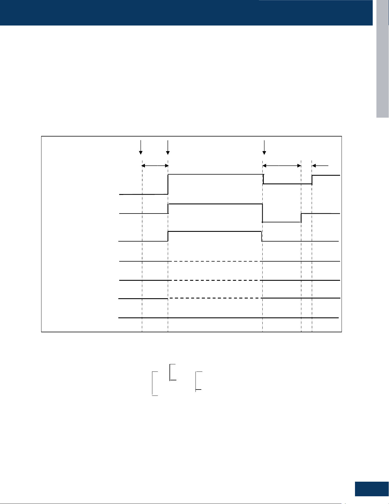
Send oil return signal oil return begins oil return over
60s ref. eliminated 30s
Oil return frequency auto frequency
Low frequency
Inverter compressor auto frequency
350 pulses(E)
running indoor EEV auto angle auto angle
120 pulses(E)
80(E)
stopped indoor EEV OFF angle 5(E) OFF angle 5(E)
Outdoor motor AUTO AUTO (TC or ambient temp. control) AUTO
running indoor motor AUTO AUTO (set fan speed) AUTO
stopped indoor motor STOP STOP STOP
4-way valve OFF OFF OFF
MULTI:
D: Entering Conditions
When the compressor running frequency is lower than 58Hz (E) continuously for 8 hrs, the system
will enter the oil return cycle.. In the course of mode changeover, manual unit stop or protective
unit stop, the time will be accumulative. After the compressor restarts up, the time will be counted
continuously. In a continuous 8 hrs, if the compressor running frequency is not less than 72Hz for
over 10 minutes continuously, the accumulative time will be cleared. Also after the heating
defrosting, the time will be cleared.
F: Error Code Occurrence During Oil Return Cycle
If the system stops during an oil return cycle due to an error code, the cycle timing will resume
when the system restarts after the error is cleared.
If there is a switch from heating to cooling, or from cooling to heating during the oil return cycle
timing, and the system stops due to an error code, the oil return cycle will occur immediately
when the error code is cleared.
Oil Return in Cooling Mode:
Oil Return Cycle
When the compressor is operating at low load conditions, or the operating frequency has been below 70Hz continuously for 4 hours, the
system will enter the oil return cycle. This ensures that oil which may be trapped within the system at low loads will return to the compressor
crankcase.
If a 4-hour low speed run time has occurred, the oil return procedure initiates by automatically ramping up the compressor speed to at least
85Hz for a pre-set time, up to a 9-minute maximum. The higher speed will wick hiding oil into the now faster-moving refrigerant and deposit
itinthecompressorcrankcase.Toavoidoccupantdiscomfortwhentheoilreturncycleisactive,theindoorfanshutso.
Should an error code result in a system shutdown, the oil return cycle timing will resume when the error code has been cleared.
Oil Return in Cooling Mode
Oil Return Exit Conditions, Cooling:
1 minute later after oil return is over
& Td Tc‐ >86℉(30 ℃)
OR OR Ts Tc2AVE‐ >86℉(30 ℃)
Tc2AVE<
Max. 10 minutes
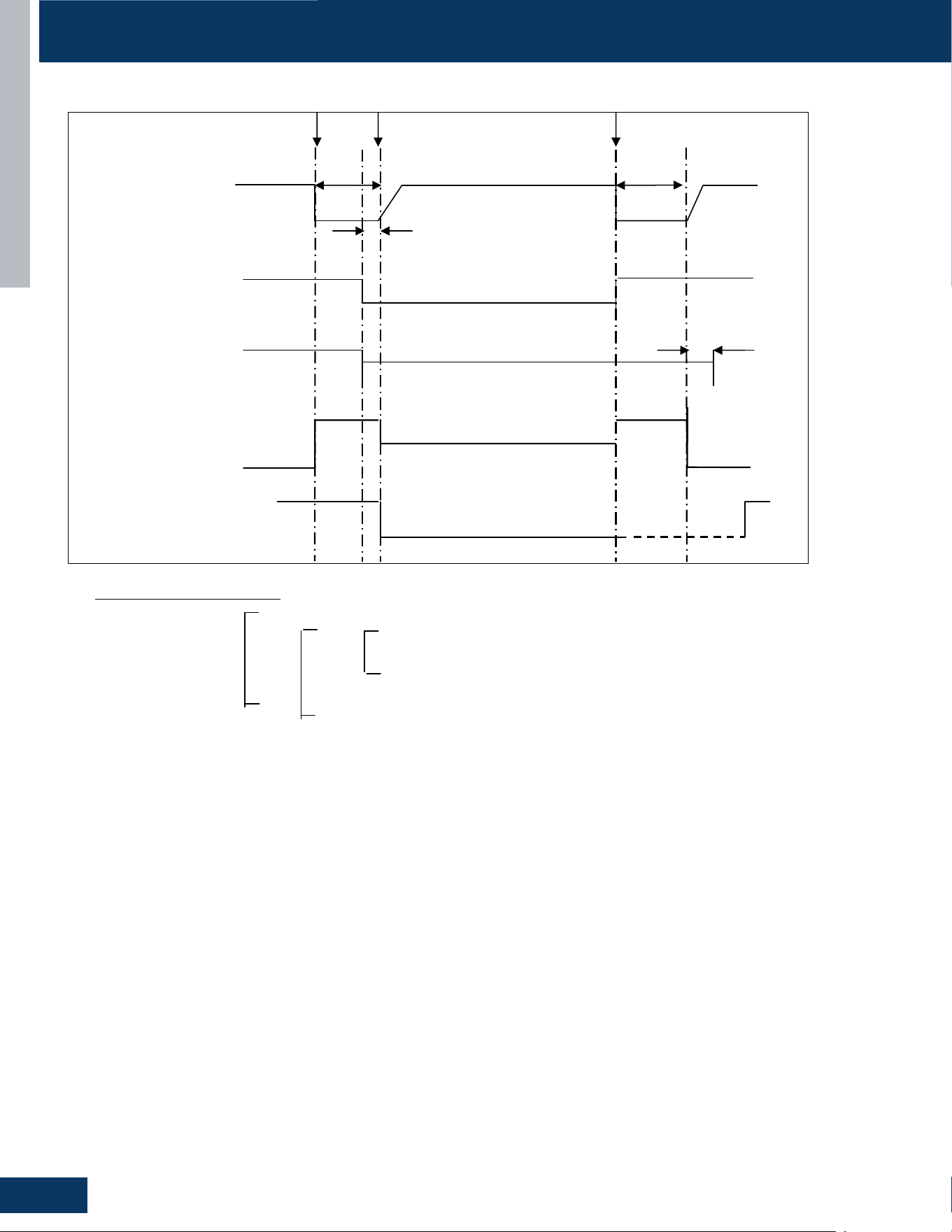
Oil Return in Heating Mode
Oil Return Exit Conditions, Heating:
Max. 9 minutes (E)
OR OR Td Tc‐ < for 30s continuously(5 minutes later, begin
to count)
& Ts Tc2AVE‐ < for 30s continuously(5 minutes later,
begin to count)
Running for min. 5 minutes
Send oil return signal oil return begins oil return over
Inverter compressor
indicated FQCY 60s oil return FQCY 60s soft startup
0HZ 0HZ
5s
Outdoor motor AUTO AUTO
AUTO (TC control)
4-way valve ON
OFF
15s
450 pulses 450 pulses
350 pulses
All expansion valves auto angle auto angle
Indoor fan motor ON
OFF
Cold air proving mode
-31℉(-35 ℃)
68℉(20 ℃)
59℉(15 ℃)
OPERATION
OUTDOOR UNITS
B18
ENGLISH
Oil Return Exit Conditions, Cooling:
1 minute later after oil return is over
& Td Tc‐ >86℉(30 ℃)
OR OR Ts Tc2AVE‐ >86℉(30 ℃)
Tc2AVE<
Max. 10 minutes
Oil Return in Heating Mode
Oil Return Exit Conditions, Heating:
Max. 9 minutes (E)
OR OR Td Tc‐ < for 30s continuously(5 minutes later, begin
to count)
& Ts Tc2AVE‐ < for 30s continuously(5 minutes later,
begin to count)
Running for min. 5 minutes
Send oil return signal oil return begins oil return over
Inverter compressor indicated FQCY 60s oil return FQCY 60s soft startup
0HZ 0HZ
5s
Outdoor motor AUTO AUTO
AUTO (TC control)
4-way valve ON
OFF 15s
450 pulses 450 pulses
350 pulses
All expansion valves auto angle auto angle
Indoor fan motor ON
OFF Cold air proving mode
-31℉(-35 ℃)
68℉(20 ℃)
59℉(15 ℃)
Oil Return Exit Conditions, Cooling:
1 minute later after oil return is over
& Td Tc‐ >86℉(30 ℃)
OR OR Ts Tc2AVE‐ >86℉(30 ℃)
Tc2AVE<
Max. 10 minutes
Oil Return in Heating Mode
Oil Return Exit Conditions, Heating:
Max. 9 minutes (E)
OR OR Td Tc‐ < for 30s continuously(5 minutes later, begin
to count)
& Ts Tc2AVE‐ < for 30s continuously(5 minutes later,
begin to count)
Running for min. 5 minutes
Send oil return signal oil return begins oil return over
Inverter compressor
indicated FQCY 60s oil return FQCY 60s soft startup
0HZ 0HZ
5s
Outdoor motor AUTO AUTO
AUTO (TC control)
4-way valve ON
OFF
15s
450 pulses 450 pulses
350 pulses
All expansion valves auto angle auto angle
Indoor fan motor ON
OFF
Cold air proving mode
-31℉(-35 ℃)
68℉(20 ℃)
59℉(15 ℃)
Oil Return in Heating Mode
OPERATION
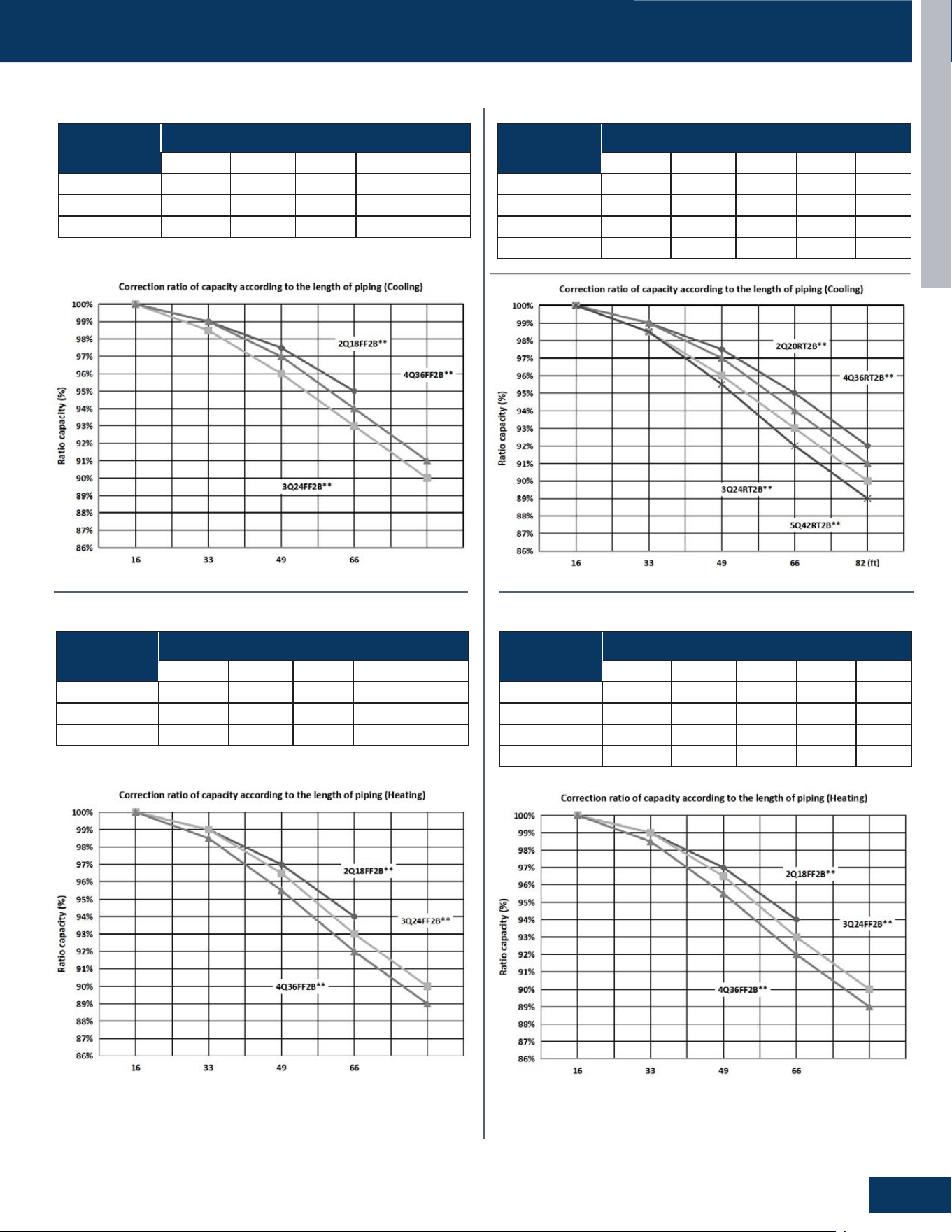
OUTDOOR UNITS
B19
ENGLISH
Correction Ratio of Capacity According to the Length of Piping
Cooling
Pipe length (ft)
16 33 49 66 82 (ft)
2G18AD2BEA 100.0% 99.0% 97.5% 95.0%
3G24AD2BEA 100.0% 98.5% 96.0% 93.0% 90.0%
4G36AD2BEA 100.0% 99.0% 97.0% 94.0% 91.0%
Heating
Pipe length (ft)
16 33 49 66 82 (ft)
2G18AD2BEA 100.0% 99.0% 97.0% 94.0%
3G24AD2BEA 100.0% 99.0% 96.5% 93.0% 90.0%
4G36AD2BEA 100.0% 98.5% 95.5% 92.0% 89.0%
Heating
Pipe length (ft)
16 33 49 66 82 (ft)
2G20ED2BEA 100.0% 99.0% 97.0% 94.0% 91.0%
3G24ED2BEA 100.0% 99.0% 96.5% 93.0% 90.0%
4G36ED2BEA 100.0% 98.5% 95.5% 92.0% 89.0%
5G42ED2BEA 100.0% 98.0% 94.5% 91.0% 88.0%
Heating
Pipe length (ft)
16 33 49 66 82 (ft)
2G20ED2BEA 100.0% 99.0% 97.5% 95.0% 92.0%
3G24ED2BEA 100.0% 98.5% 96.0% 93.0% 90.0%
4G36ED2BEA 100.0% 99.0% 97.0% 94.0% 91.0%
5G42ED2BEA 100.0% 98.5% 95.5% 92.0% 89.0%
OPERATION
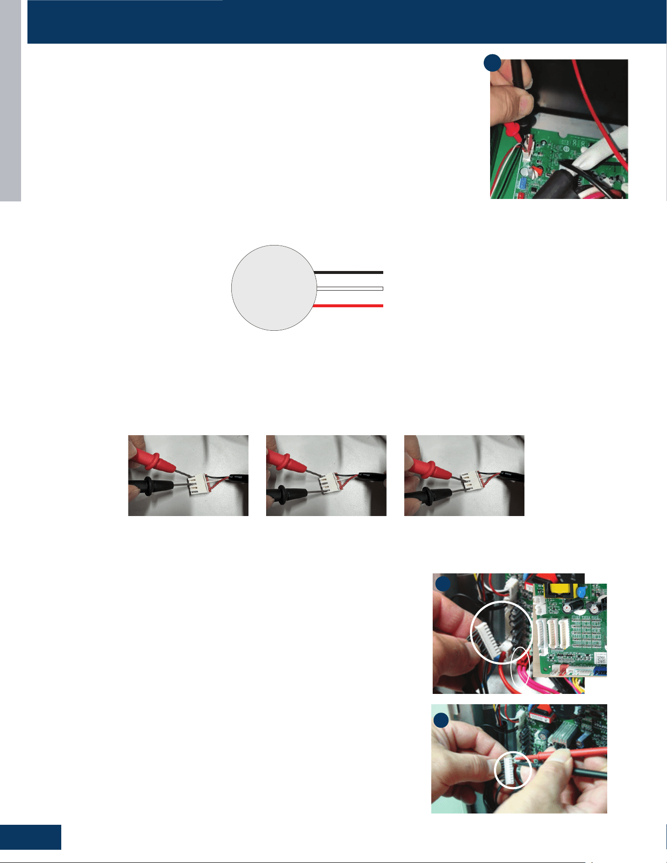
OUTDOOR UNITS
B20
ENGLISH
SERVICE PROCEDURES
Outdoor Fan Motor
Check that the wiring and plug connections are in good condition.
If the outdoor unit fan motor does not run, or the Service Monitor Board indicates an error code of 09,
check the following voltages at connector CN11 on the outdoor unit PCB. Set the meter to read DC volts
with a minimum voltage range of 350 volts. All voltage values are approximate. Initiate forced cooling.
1. DC voltage between the Red and Black wires should read 310 - 334VDC. This is the main voltage for
powering the fan motor.
2. DC voltage between the White and Black wires should read 310-334VDC. This is the main voltage for
powering the fan motor.
3. DC voltage between the Red and White wires should read 310-334VDC. This is the main voltage for
powering the fan motor.
If the outdoor fan initially runs, increases speed then stops, and the Service Monitor Board indicates an
error code of 09, the feedback circuit is not functioning. Check that the wiring and plug connections are in
good condition.
1
DC
Motor
310 VDC
310 VDC
Red
Black
White
Note: PCB design may vary by
model number
Temperature Sensor
Thetemperaturesensorsarenegativecoecientthermistors,inwhichresistancedecreases
as temperature rises. Should the sensors fail, the PCB will generate an appropriate error
code.
To check the calibration of the sensors:
1. Shutopowertotheoutdoorunit.
2. Disconnect the sensor at the circuit board plug.
3. Measure the temperature of the air surrounding the sensor.
4. Measure the electrical resistance of the sensor using needle probes. Do not force
standard probes into the sensor plug.
5. Compare the measured resistance of the sensor against the resistance/temperature
specications(Seechartinreferencesection)
6. Ifthesensorresistanceisoutsideofthespecicationtolerancesshownonthe
resistance/temperature table, replace the sensor.
2
4
Note: PCB design may vary
by model number
Fault Detection Methods for DC Motors
Rest the motor at room temperature (25°C) for a minimum of 2 hours. Next, use a multimeter to measure the resistance value between the red
andblack,redandwhite,blackandwhitemotorleads.Thedierencebetweenthemeasuredvaluesshouldbenomorethan3%.
Note that at dierent temperatures or uctuating temperatures, the tolerance limit will uctuate.
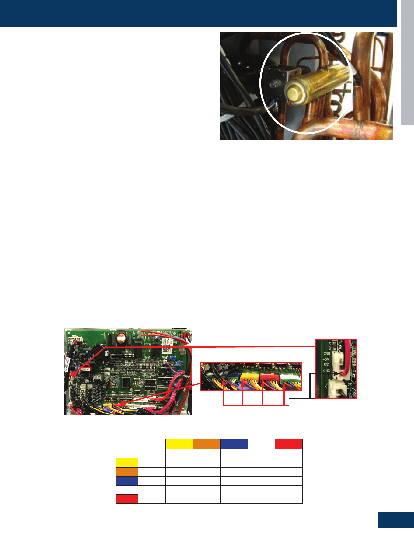
OUTDOOR UNITS
B21
ENGLISH
SERVICE PROCEDURES
4-Way Valve
The 4-way valve will control the direction of hot gas discharge via an
internal slide assembly. The valve has a line voltage solenoid that is
energized in heat mode. The solenoid will direct the internal slide to
send the hot gas to the indoor coil. During cooling mode de-energized
operation, the internal slide will direct compressor hot gas to the outdoor
coil.
4-way valves may have a failure of the electrical solenoid that prevents
the valve from shifting, or they may become stuck due to debris lodging
inside the valve body. If the valve fails to direct the hot gas in the proper
direction, temperature sensors within the outdoor unit will detect the
problem and generate an error code.
If the valve fails to shift the hot gas to the proper coil, or it only
partially shifts, perform the following:
1. Check for correct refrigerant charge, and that all other operating parameters have been met.
2. In the heating mode, the solenoid will shift after a short time delay. Check for line voltage to the solenoid coil.
3. If the valve has voltage but fails to shift the hot gas to the indoor coil, shut the system down and unplug the 4-way valve from the PCB plug.
4. Use an ohmmeter to check continuity through the solenoid coil. If the coil resistance does not match the chart in this manual, or if a winding
shows open or shorted, the solenoid coil will have to be replaced.
5. If the coil resistance is within the tolerance, use a magnet along the valve body to determine the location of the piston. If one end of the
piston is against the end of the valve body, it is stuck and the valve must be replaced.
6. Partial shifting of the valve can be detected by measuring the temperature of the suction gas where it enters the reversing valve and then
comparingthattemperaturetothetemperatureofthesuctiongasexitingthe4-wayvalve.Thereshouldbenomorethan3Fdierence.
Excessive temperature rise through the suction gas path is an indication of a stuck piston. If the piston will not become free by switching
from heating to cooling several times, a slight tapping on the valve body, or by using a powerful magnet, the valve will require replacement.
12VDC
EEV Terminals
Electronic Expansion Valve (EEV)
1. ChecktoseeiftheElectronicexpansionvalve(EEV)connectoriscorrectlyandrmlyinsertedinthePCB.
2. Turnthepoweroandbackonagain,
3. Check to see whether the EEV have a reposition sound. This sound will start after approx 2 min. If the EEV doesn’t have noise,
please disconnect the connector and check the resistance (refer to resistance tables below).
4. If the resistance is OK, The PCB may be at fault.
Note: PCB design may vary by
model number
EEV (6-pin, 5 wire)
White Yellow Orange Blue X Red
White
-
92Ω 92Ω 92Ω - 46Ω
Yellow
- -
92Ω 92Ω - 46Ω
Orange
- - -
92Ω - 46Ω
Blue
- - - - -
46Ω
X
- - - - - -
Red
- - - - - -
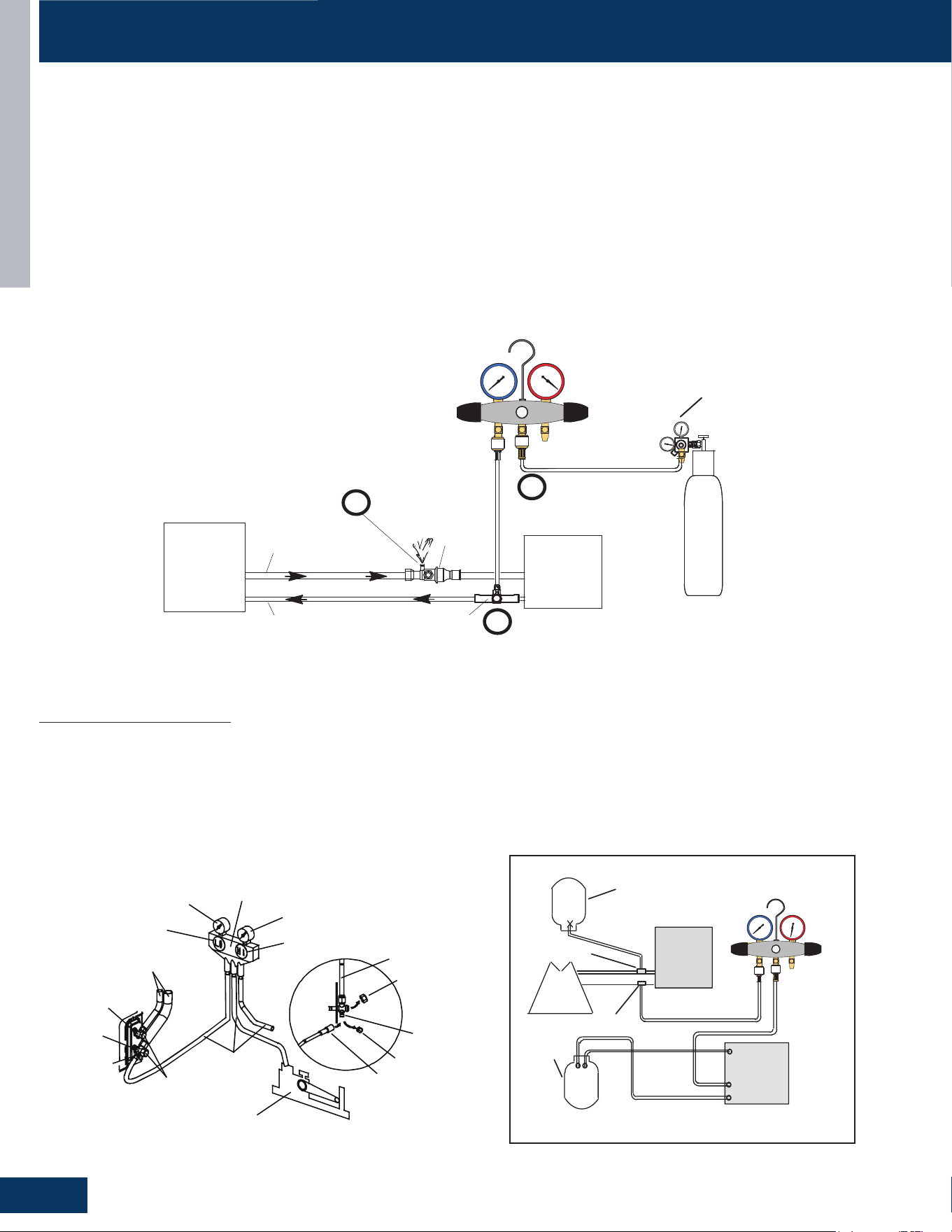
OUTDOOR UNITS
B22
ENGLISH
System Evacuation
NOTE: Do not open service valve.
• Remove the suction line cap and attach a micron gauge and vacuum pump. The port is 5/16”. An adapter may be needed.
• Evacuate the system to at least 350 microns.
• Close the vacuum pump valve and check the micron gauge. If the gauge rises above 150 microns within 60 seconds, the evacuation is
incomplete or there is a leak in the system. If the gauge does not rise above 150 microns in 60 seconds, the evacuation is complete.
• Once evacuation is complete, remove the adapter and hose connection from the suction line port and replaced the cap.
24
31-5001053 Rev. 0
Before brazing, ensure the system is fully
recovered of all refrigerant. Application of a
brazing torch to a pressurized system may
result in ignition of the refrigerant and oil
mixture. Check the high and low pressures
before applying heat.
WARNING
Brazing alloys and flux contain materials which are
hazardous to your health.
Avoid breathing vapors or fumes from brazing operations.
Perform operations only in well-ventilated areas.
Wear gloves and protective goggles or face shield to
protect against burns.
Wash hands with soap and water after handling brazing
alloys and flux.
WARNING
Use a manifold gauge set designed for use on R-454B
refrigerant systems.
NOTE
Refrigerant Piping - Brazing Procedures
1. CUT AND DEBUR
Cut ends of the refrigerant lines square (free from nicks
or dents) and debur the ends. The pipe must remain
round. Do not crimp end of the line.
2. CAP AND CORE REMOVAL
Remove service cap and core from both the vapor and
liquid line service ports.
LIQUID LINE SERVICE
VALVE
SERVICE
PORT
CORE
SERVICE PORT
CAP
SERVICE
PORT
CORE
SERVICE
PORT CAP
VAPOR LINE SERVICE
VALVE
LINE SET SIZE MATCHES
SERVICE VALVE CONNECTION
CUT AND DEBUR
COPPER TUBE
STUB
REFRIGERANT LINE
REDUCER
SERVICE VALVE
CONNECTION
LINE SET SIZE IS SMALLER
THAN CONNECTION
DO NOT CRIMP SERVICE VALVE
CONNECTOR WHEN PIPE IS
SMALLER THAN CONNECTION
OUTDOOR
UNIT
LIQUID LINE
VAPOR LINE
LIQUID LINE SERVICE
VALVE
VAPOR LINE
SERVICE
VALVE
ATTACH
GAUGES
INDOOR
UNIT
VAPOR SERVICE PORT MUST BE OPEN
TO ALLOW EXIT POINT FOR NITROGEN
NITROGEN
HIGHLOW
USE REGULATOR TO FLOW
NITROGEN AT 1 TO 2 PSIG.
B
A
C
WHEN BRAZING LINE SET TO
SERVICE VALVES, POINT FLAME
AWAY FROM SERVICE VALVE.
3. ATTACH THE MANIFOLD GAUGE SET FOR BRAZING LIQUID AND VAPOR LINE SERVICE VALVES
Flow regulated nitrogen (at 1 to 2 psig) through the low-side refrigeration gauge set into the liquid line service port valve,
and out of the vapor line service port valve.
A - Connect gauge set low pressure side to liquid line service valve (service port).
B - Connect gauge set center port to bottle of nitrogen with regulator.
C - Remove core from valve in vapor line service port to allow nitrogen to escape.
20
31-5001053 Rev. 0
Conventional Line Set Installation: Pipe Connection
• Attach the flare nuts to the outdoor Service Valve, Torque
the fittings according to the specifications shown in the
torque chart below.
NOTE: Forced fastening without careful centering may
damage the threads and cause a refrigerant leak.
Pipe Diameter(ǿ) Fastening torque
Liquid side 6.35mm(1/4”) 18N.m/13.3Ft.lbs
Liquid/Gas side 9.52mm(3/8”) 42 N.m/30.1Ft.lbs
Gas side 12.7mm(1/2”) 55N.m/40.6Ft.lbs
Gas side 15.88mm(5/8”) 60 N.m/44.3Ft.lbs
Gas side 19.05mm(3/4”) 100N.m/73.8Ft.lbs
• Add additional refrigerant charge if needed before you
open outdoor service valves
• Record the amount of refrigerant added in permanent ink at
the line set length location entered earlier.
Service Valves
Corrugate Gas Pile
Liquid Pipe
• Two wrenches are required to join the flare connection; one
standard wrench and one torque wrench adjusted to the
proper settings.
• Repeat the process for attaching the other end of the
line set.
IMPORTANT: A 5/16” female by 1/4” male adapter will be required to connect conventional gauge hoses to
the service valves.
Refrigerant Hose
Manifold Gauge
Low side
High Side
Low Side Valve
High Side Valve
Refrigerant Lines
(to indoor unit)
Liquid Valve
Gas Valve
Service Port
Cap
Refrigerant
Hose
Vacuum Pump
Cap
Service Pipe
Cap
Connection Pipe
NOTE: It shows the gauge connection will need to have the high side gauge hose connected to the high side liquid valve so
both lines can be evacuated and leak checked.
Figure 12.
Figure 14.
Model Extension
Extension
Type
Extension
Length
(in)
Line Set
Receiving End
Pipe Diameter
(in)
Flared
End Pipe
Diameter
(in)
Line Set
Connection
Type
24K
Suction
Extension
Flexible 7-3/4
3/4 5/8
Braze and
Mechanical
Liquid
Extension
3/8 3/8
Braze and
Mechanical
36K
Suction
Extension
Flexible 33-1/2
3/4 3/4
Braze and
Mechanical
7/8 3/4 Braze
Liquid
Extension
3/8 3/8
Braze and
Mechanical
60K
Suction
Extension
Flexible 35-3/8
3/4 3/4
Braze and
Mechanical
7/8 3/4 Braze
Liquid
Extension
3/8 3/8
Braze and
Mechanical
Figure 13.
Half union Flare nut
Spanner Torque wrench
Pipe Matching Capabilities of Pipe Extensions
22 31-5001053 Rev. 0
Connect Gauges and Equipment for Flushing
Procedure
LOW HIGH
EXISTING
INDOOR
UNIT
GAUGE
MANIFOLD
CYLINDER CONTAINING
CLEAN R-454B TO BE
USED FOR FLUSHING
(Positioned to deliver liquid
refrigerant)
LIQUID LINE SERVICE
VALVE
INLET
DISCHARGE
TANK
RETURN
CLOSED
OPENED
RECOVERY
CYLINDER
RECOVERY MACHINE
NEW
OUTDOOR
UNIT
VAPOR LINE
SERVICE VALVE
VAPOR
LIQUID
1
1
2
3
4
Figure 17. Connecting Gauges
1. Cylinder with clean R-454B (positioned to deliver liquid
refrigerant) to the vapor service valve.
2. Refrigerant gauge set (low side) to the liquid line valve.
3. Refrigerant gauge set center port to inlet on the recovery
machine with an empty recovery tank connected to the
gauge set.
4. Connect recovery tank to recovery machine per machine
instructions.
Flushing Line Sets
If the unit will be installed in an existing system that uses
an indoor unit or line sets charged with R-22 refrigerant,
installer must perform the following flushing procedure.
NOTE: Existing system components (including line set and
indoor coil) must be an AHRI match with the unit in order to
fulfill unit warranty requirements.
Fire, Explosion and Personal Safety
hazard. Failure to follow this warning
could result in damage, personal injury or
death.
Never use oxygen to pressurize or
purge refrigeration lines. Oxygen, when
exposed to a spark or open flame, can
cause fire and/or an explosion, that could
result in property damage, personal injury
or death.
WARNING
When using a high pressure gas such as
nitrogen to pressurize a refrigeration or air
conditioning system, use a regulator that can
control the pressure down to 1 or 2 psig (6.9 to
13.8 kPa).
WARNING
Refrigerant must be reclaimed in accordance with national
and local codes.
WARNING
1. Set the recovery machine for liquid recovery and start
the recovery machine. Open the gauge set valves to
allow the recovery machine to pull a vacuum on the
existing system line set and indoor unit coil.
2. Position the cylinder of clean R-454B for delivery of
liquid refrigerant and open its valve to allow liquid
refrigerant to ow into the system through the vapor
line valve. Allow the refrigerant to pass from the cylinder
and through the line set and the indoor unit coil before it
enters the recovery machine.
3. After all of the liquid refrigerant has been recovered,
switch the recovery machine to vapor recovery so that
all of the R-454B vapor is recovered. Allow the recovery
machine to pull the system down to 0.
4. Close the valve on the inverted R-454B drum and the
gauge set valves. Pump the remaining refrigerant out of
the recovery machine and turn the machine o.
SERVICE PROCEDURES
Leak Test
Perform the following steps for EACH line set. The primary service valve has a 5/16” port. An adapter may be necessary.
• Remove the cap on the service valve.
• Using a tank of dry nitrogen and approved regulator, charge the system with 150 psig of dry nitrogen using mini-split adapter to connect the
valve.
• Checkforleaksatthearettingsusingsoapbubblesoranotherdetectiondevice.Ifaleakisdetected,makerepairstothettingsand
recheck. Proceed if no leaks are detected within 3 minutes.
• Using the same tank/regulator, charge the system to 300 psig.
• Recheck for leaks. Proceed if no leaks are detected within 3 minutes.
• Using the same tank/regulator, charge the system to 500 psig.
• Recheck for leaks. Keep system pressurized for at least 20 minutes.
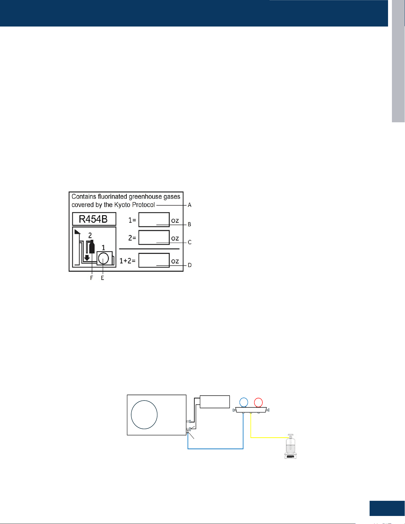
OUTDOOR UNITS
B23
ENGLISH
SERVICE PROCEDURES
Refrigerant Charging
• Add any additional refrigerant after evacuation using a digital scale.
• NOTE: Charge liquid only.
• Fill out the refrigerant charge label (See illustration below) using permanent ink.
• Place the factory refrigerant charge found on the outdoor nameplate in box number 1.
• Place the amount of additional refrigerant added in box number 2.
• Add boxes 1 and 2 together and place the value in the sum box (D).
• Adhere the completed label in the proximity of the product charging port and under the outside unit valve cover.
• If no sticker is found, write the charge amounts on outdoor unit with permanent marker above the charging port,
• Remove the cap from the liquid line valve. Using a hex wrench, open the valve, then replace and tighten the cap securely to avoid leaks.
• Remove the cap from the suction line valve. Using a hex wrench, open the valve, then replace and tighten the cap securely to avoid leaks.
• Wrap the line set, drain line, and 14/4 AWG wiring starting at the bottom of the bundle with an overlap type wrap until you reach the piping
hole.
• Use a sealant to seal the piping hole opening on both sides of the wall in order to prevent drafts, weather, or pests from entering the building.
• ThisproductcontainsuorinatedgreenhousegasescoveredbytheKyotoProtocol.Donotventintotheatmosphere.
Refrigerant type: R-454B
GWP* value: 466
GWP = global warming potential
1. Close the high-pressure manifold gauge valves. Connect the gauge charging port hose to the refrigerant tank, and connect the low-side
hose to the ODU gas line service port.
2. Evacuate the lineset between the pressure gauge and the refrigerant tank: Loosen the repair port connecting wire slightly, open the
refrigeranttankvalveslightly,andevacuatetheconnectingpipe.Aftercompletion,tightentheconnectingpipethreadagainandopenthe
refrigerant tank valve.
3. The system must be charged with liquid refrigerant only. If the refrigerant tank does not have a siphon tube, place the refrigerant tank
upside down on an electronic scale and record the weight. If the refrigerant tank itself has a siphon tube, place the refrigerant tank upright
on an electronic scale and record the weight.
4. Open the low-pressure gauge valve, charge the system with liquid refrigerant. Record the changes in the weight of the refrigerant tank until
thespeciedweightisreached.Uponcompletion,closetherefrigeranttankvalve,removetheconnectedhosingandtightentheservice
valve cap.
1, Close the high-pressure gauge valve, connect the intermediate gauge pipe to the
refrigerant tank, and connect the low-pressure gauge pipe of the pressure gauge to the
check port of the gas pipe stop valve of the ODU.
2, Evacuate the pipeline between the pressure gauge and the refrigerant tank: Loosen
the repair port connecting wire slightly, open the refrigerant tank valve slightly, and
evacuate the connecting pipe. After completion, tighten the connecting pipe thread
again and open the refrigerant tank valve.
3,Confirm the placement direction of the refrigerant tank to ensure that the refrigerant is
injected in liquid form: if the refrigerant tank itself does not have a siphon tube, place the
refrigerant tank upside down on an electronic scale and record the weight; If the
refrigerant tank itself has a siphon tube, place the refrigerant tank upright on an
electronic scale and record the weight.
4, Open the low-pressure gauge valve, cha
rge the system with refrigerant, and record
the changes in the weight of the refrigerant tank until the specified weight is reached.
Close the refrigerant tank valve, remove the connecting pipe, and tighten check hole
cap.
Outdoor unit
Liquid stop valve
Service port
Indoor unit
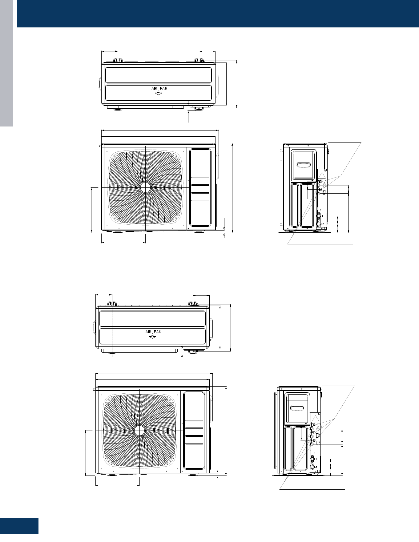
OUTDOOR UNITS
B24
ENGLISH
DIMENSION DRAWINGS
2G18AD2BEA
130
130
340
368
890
700
19
Liquid Pipe
2*Ø6.35(Flared)1/4
Gas Pipe
2*Ø9.52(Flared)3/8
343
353
38
915
62
60
60
69
307
3G24AD2BEA
130
130
340
368
890
700
19
Liquid Pipe
3*Ø6.35(Flared)1/4
Gas Pipe
3*Ø9.52(Flared)3/8
343
353
38
915
62
120
120
69
247
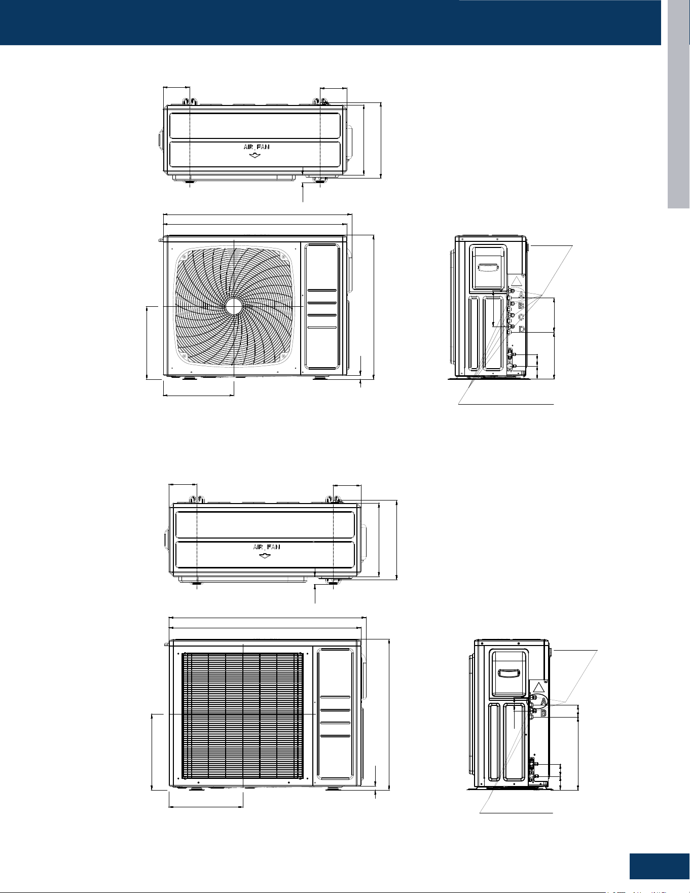
OUTDOOR UNITS
B25
ENGLISH
DIMENSION DRAWINGS
4G36AD2BEA
130
130
372
402
920
765
16
Liquid Pipe
4*Ø6.35(Flared)1/4
Gas Pipe
3*Ø9.52(Flared)3/8(A,B,C Unit)
1*Ø12.7(Flared)1/2(D Unit)
360
379
38
945
57
180
180
64
252
2G20ED2BEA
130
130
372
402
920
765
16
Liquid Pipe
2*Ø6.35(Flared)1/4
Gas Pipe
2*Ø9.52(Flared)3/8
360
379
38
945
57
60
60
64
372
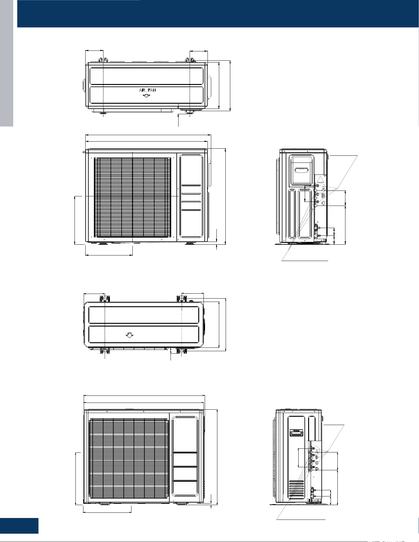
OUTDOOR UNITS
B26
ENGLISH
3G24ED2BEA
130
130
372
402
920
765
16
Liquid Pipe
3*Ø6.35(Flared)1/4
Gas Pipe
3*Ø9.52(Flared)3/8
360
379
38
945
57
120
120
64
312
4G36ED2BEA
185
185
461
16
399
411
52
1040
840
1060
400
Liquid Pipe
4*Ø6.35(Flared)1/4
Gas Pipe
3*Ø9.52(Flared)3/8(A,B,C Unit)
1*Ø12.7(Flared)1/2(D Unit)
62
180
180
76
340
DIMENSION DRAWINGS
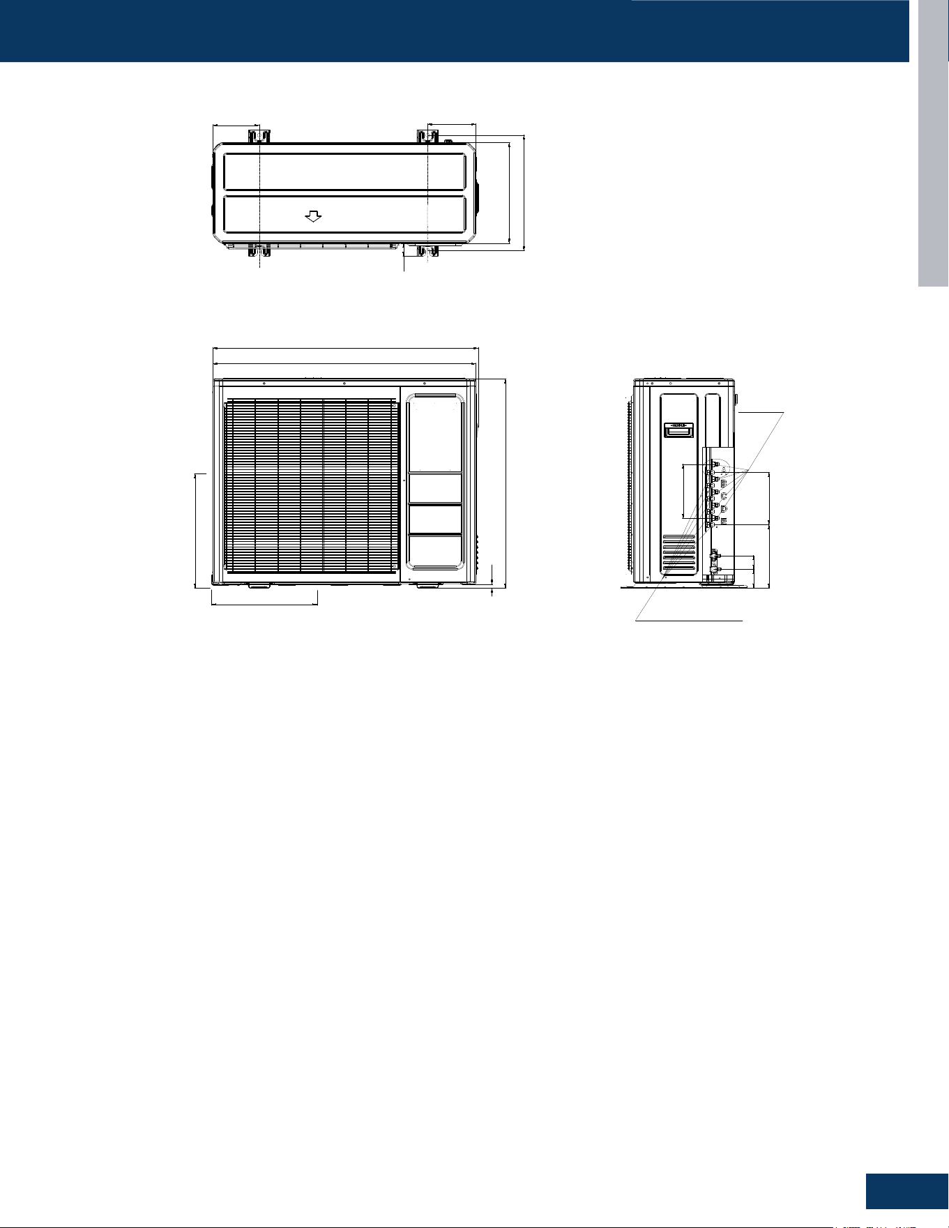
OUTDOOR UNITS
B27
ENGLISH
5G42ED2BEA
185
185
461
16
399
411
52
1040
840
1060
400
Liquid Pipe
5*Ø6.35(Flared)1/4
Gas Pipe
3*Ø9.52(Flared)3/8(A,B,C Unit)
2*Ø12.7(Flared)1/2(D,E Unit)
62
240
240
76
280
DIMENSION DRAWINGS
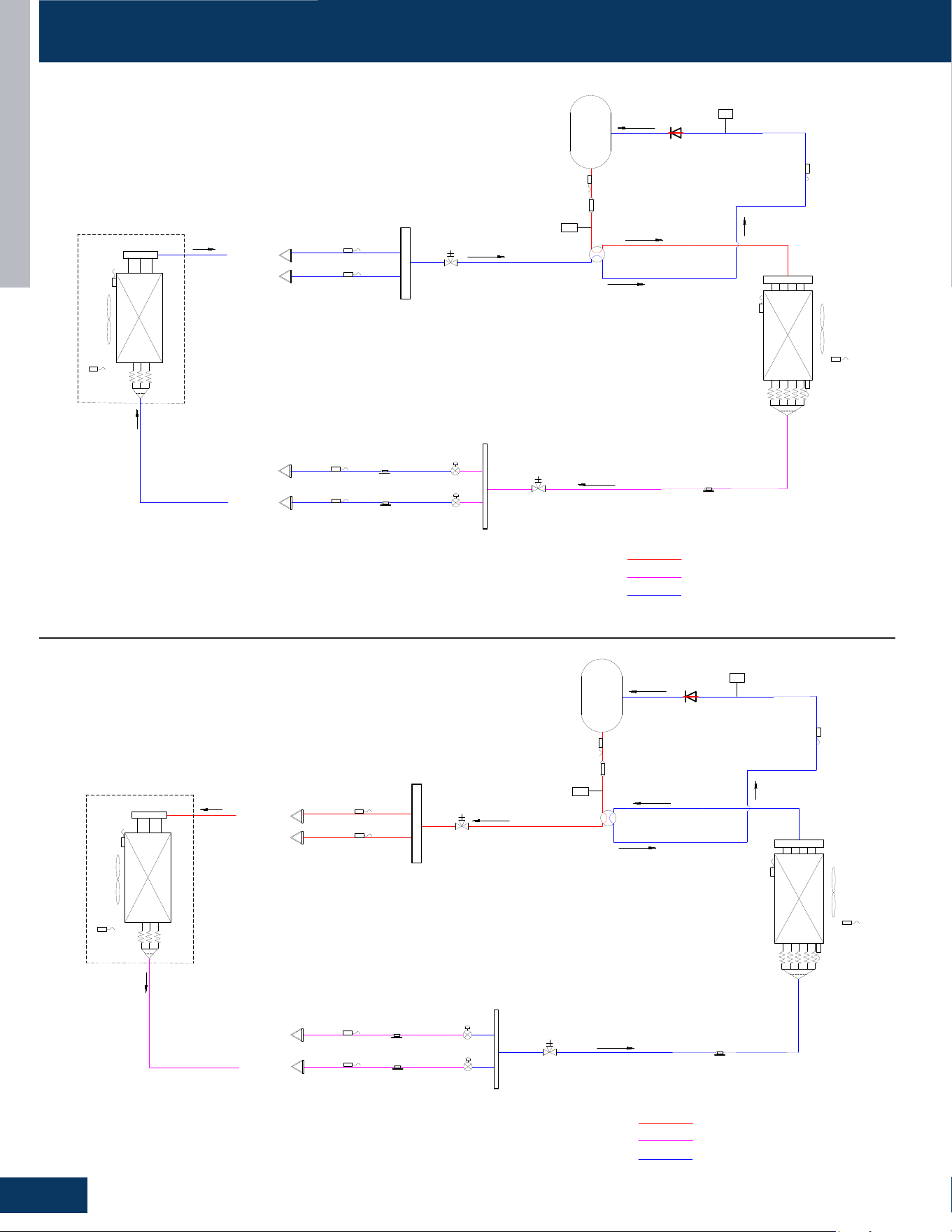
OUTDOOR UNITS
B28
ENGLISH
PIPING DIAGRAMS
2G18AD2BEA Cooling
High Pressure Swtich
Four Way Valve
4WV
Low Pressure Switch
LP
Gas Stop Valve
with
Service Port
Ø
15.88mm
(
5/8in.
)
Sensor
TC
FAN-OUT
Sensor
TA
Sensor
TE
Distributor
Liquid Stop Vavle
with
Service Port
Ø
9.52mm
(
3/8in.
)
PMV
B
Indoor Unit B
Sensor TC1
Sensor TC1
Indoor unit A
Indoor unit B
FAN-IN
Sensor
TAi
Sensor
TM
PMV
A
Indoor Unit A
High temperature,high pressure,gas
High temperature,high pressure,liquid
Low temperature,low pressure,gas/liquid
Liquid Pipe
Gas Pipe
Sensor
TC2
Sensor
TC2
Sensor
TS
LPS
HPS
Heat
Exchanger
Heat
Exchanger
Electronic Expansion Valve
Electrionc Expansion Valve
Filter
Filter
Filter
Compressor
INV
Sensor
TD
Silencer
HP
Single Way Valve
2G18AD2BEA Heating
High Pressure Swtich
Four Way Valve
4WV
Low Pressure Switch
LP
Gas Stop Valve
with
Service Port
Ø
15.88mm
(
5/8in.
)
Sensor
TC
FAN-OUT
Sensor
TA
Sensor
TE
Distributor
Liquid Stop Vavle
with
Service Port
Ø
9.52mm
(
3/8in.
)
PMV
B
Indoor Unit B
Sensor TC1
Sensor TC1
Indoor unit A
Indoor unit B
FAN-IN
Sensor
TAi
Sensor
TM
PMV
A
Indoor Unit A
High temperature,high pressure,gas
High temperature,high pressure,liquid
Low temperature,low pressure,gas/liquid
Liquid Pipe
Gas Pipe
Sensor
TC2
Sensor
TC2
Sensor
TS
LPS
HPS
Heat
Exchanger
Heat
Exchanger
Electronic Expansion Valve
Electrionc Expansion Valve
Filter
Filter
Filter
Compressor
INV
Sensor
TD
Silencer
HP
Single Way Valve
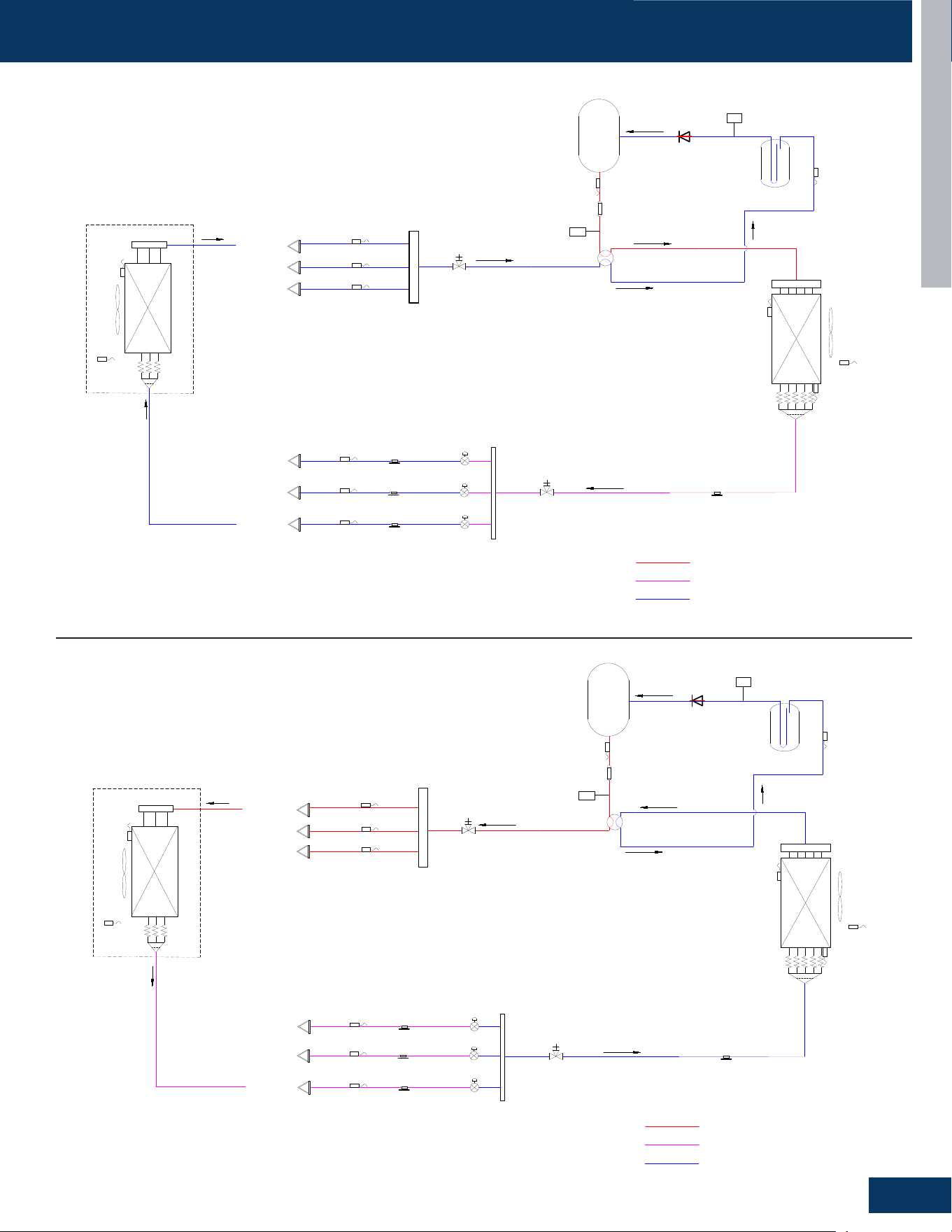
OUTDOOR UNITS
B29
ENGLISH
PIPING DIAGRAMS
3G24AD2BEA / 3G24ED2BEA Cooling
High Pressure Swtich
Four Way Valve
4WV
Low Pressure Switch
LP
Gas-liquid
Separator
Gas Stop Valve
with
Service Port
Ø
15.88mm
(
5/8in.
)
Sensor
TC
FAN-OUT
Sensor
TA
Sensor
TE
Distributor
Liquid Stop Vavle
with
Service Port
Ø
9.52mm
(
3/8in.
)
PMV
B
Indoor Unit B
Sensor TC1
Sensor TC1
Indoor unit A
Indoor unit B
FAN-IN
Sensor
TAi
Sensor
TM
PMV
A
Indoor Unit A
High temperature,high pressure,gas
High temperature,high pressure,liquid
Low temperature,low pressure,gas/liquid
Liquid Pipe
Gas Pipe
Sensor
TC2
Sensor
TC2
Sensor
TS
LPS
HPS
Heat
Exchanger
Heat
Exchanger
Electronic Expansion Valve
Electrionc Expansion Valve
Filter
Filter
Filter
Compressor
INV
Sensor
TD
Silencer
HP
Sensor TC1
Indoor unit C
PMV
C
Indoor Unit C
Sensor
TC2
Electrionc Expansion Valve
Filter
Single Way Valve
3G24AD2BEA / 3G24ED2BEA Heating
High Pressure Swtich
Four Way Valve
4WV
Low Pressure Switch
LP
Gas-liquid
Separator
Gas Stop Valve
with
Service Port
Ø
15.88mm
(
5/8in.
)
Sensor
TC
FAN-OUT
Sensor
TA
Sensor
TE
Distributor
Liquid Stop Vavle
with
Service Port
Ø
9.52mm
(
3/8in.
)
PMV
B
Indoor Unit B
Sensor TC1
Sensor TC1
Indoor unit A
Indoor unit B
FAN-IN
Sensor
TAi
Sensor
TM
PMV
A
Indoor Unit A
High temperature,high pressure,gas
High temperature,high pressure,liquid
Low temperature,low pressure,gas/liquid
Liquid Pipe
Gas Pipe
Sensor
TC2
Sensor
TC2
Sensor
TS
LPS
HPS
Heat
Exchanger
Heat
Exchanger
Electronic Expansion Valve
Electrionc Expansion Valve
Filter
Filter
Filter
Compressor
INV
Sensor
TD
Silencer
HP
Single Way Valve
Sensor TC1
Indoor unit C
PMV
C
Indoor Unit C
Sensor
TC2
Electrionc Expansion Valve
Filter
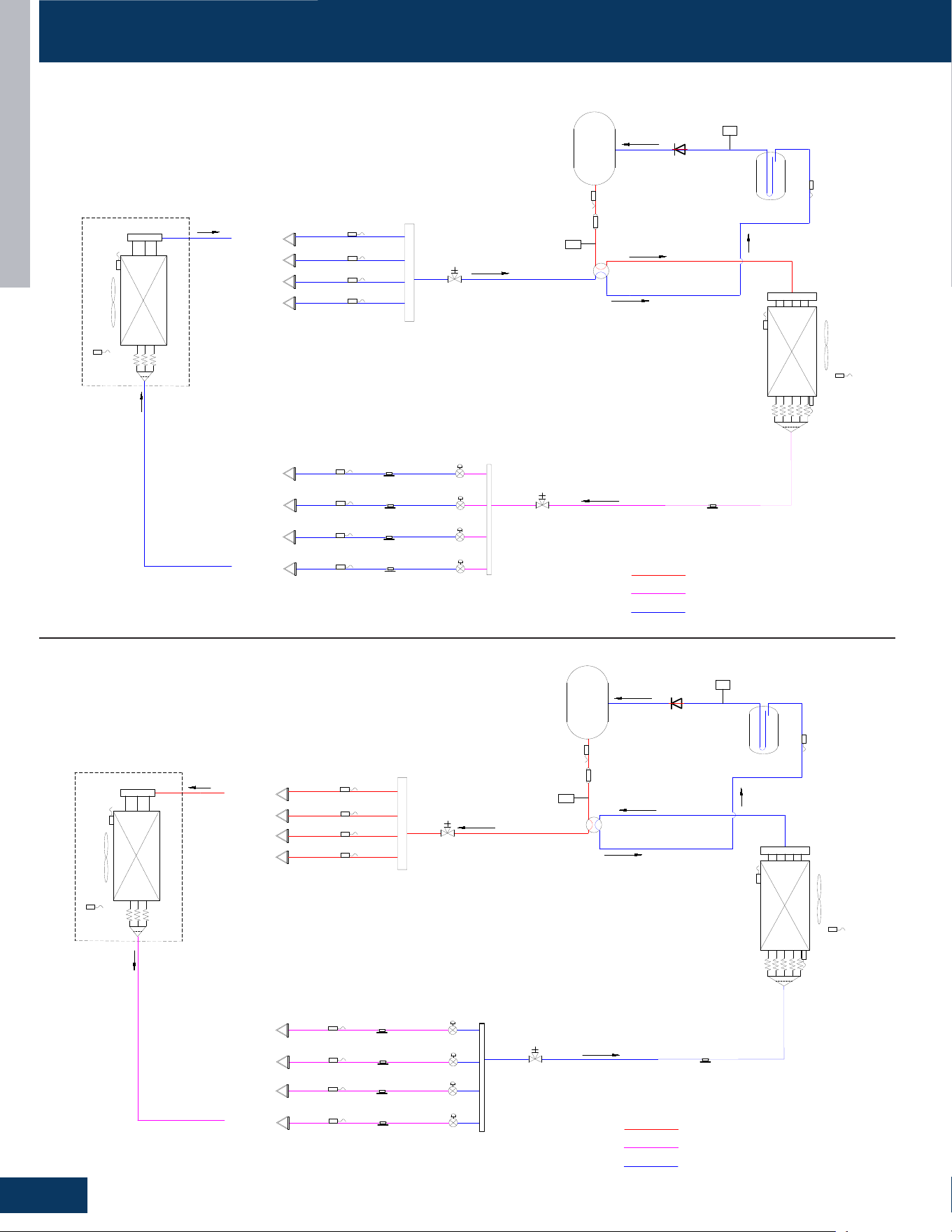
OUTDOOR UNITS
B30
ENGLISH
PIPING DIAGRAMS
4G36AD2BEA / 4G36ED2BEA Cooling
High Pressure Swtich
Four Way Valve
4WV
Low Pressure Switch
LP
Gas-liquid
Separator
Gas Stop Valve
with
Service Port
Ø
15.88mm
(
5/8in.
)
Sensor
TC
FAN-OUT
Sensor
TA
Sensor
TE
Distributor
Liquid Stop Vavle
with
Service Port
Ø
9.52mm
(
3/8in.
)
PMV
B
Indoor Unit B
Sensor TC1
Sensor TC1
Indoor unit A
Indoor unit B
FAN-IN
Sensor
TAi
Sensor
TM
PMV
A
Indoor Unit A
High temperature,high pressure,gas
High temperature,high pressure,liquid
Low temperature,low pressure,gas/liquid
Liquid Pipe
Gas Pipe
Sensor
TC2
Sensor
TC2
Sensor
TS
LPS
HPS
Heat
Exchanger
Heat
Exchanger
Electronic Expansion Valve
Electrionc Expansion Valve
Filter
Filter
Filter
Compressor
INV
Sensor
TD
Silencer
HP
Sensor TC1
Indoor unit C
Sensor TC1
Indoor unit D
PMV
D
Indoor Unit D
PMV
C
Indoor Unit C
Sensor
TC2
Sensor
TC2
Electronic Expansion Valve
Electrionc Expansion Valve
Filter
Filter
Single Way Valve
4G36AD2BEA / 4G36ED2BEA Heating
High Pressure Swtich
Four Way Valve
4WV
Low Pressure Switch
LP
Gas-liquid
Separator
Gas Stop Valve
with
Service Port
Ø
15.88mm
(
5/8in.
)
Sensor
TC
FAN-OUT
Sensor
TA
Sensor
TE
Distributor
Liquid Stop Vavle
with
Service Port
Ø
9.52mm
(
3/8in.
)
PMV
B
Indoor Unit B
Sensor TC1
Sensor TC1
Indoor unit A
Indoor unit B
FAN-IN
Sensor
TAi
Sensor
TM
PMV
A
Indoor Unit A
High temperature,high pressure,gas
High temperature,high pressure,liquid
Low temperature,low pressure,gas/liquid
Liquid Pipe
Gas Pipe
Sensor
TC2
Sensor
TC2
Sensor
TS
LPS
HPS
Heat
Exchanger
Heat
Exchanger
Electronic Expansion Valve
Electrionc Expansion Valve
Filter
Filter
Filter
Compressor
INV
Sensor
TD
Silencer
HP
Single Way Valve
Sensor TC1
Indoor unit C
Sensor TC1
Indoor unit D
PMV
D
Indoor Unit D
PMV
C
Indoor Unit C
Sensor
TC2
Sensor
TC2
Electronic Expansion Valve
Electrionc Expansion Valve
Filter
Filter

OUTDOOR UNITS
B31
ENGLISH
PIPING DIAGRAMS
2G20ED2BEA Cooling
High Pressure Swtich
Four Way Valve
4WV
Low Pressure Switch
LP
Gas-liquid
Separator
Gas Stop Valve
with
Service Port
Ø
15.88mm
(
5/8in.
)
Sensor
TC
FAN-OUT
Sensor
TA
Sensor
TE
Distributor
Liquid Stop Vavle
with
Service Port
Ø
9.52mm
(
3/8in.
)
PMV
B
Indoor Unit B
Sensor TC1
Sensor TC1
Indoor unit A
Indoor unit B
FAN-IN
Sensor
TAi
Sensor
TM
PMV
A
Indoor Unit A
High temperature,high pressure,gas
High temperature,high pressure,liquid
Low temperature,low pressure,gas/liquid
Liquid Pipe
Gas Pipe
Sensor
TC2
Sensor
TC2
Sensor
TS
LPS
HPS
Heat
Exchanger
Heat
Exchanger
Electronic Expansion Valve
Electrionc Expansion Valve
Filter
Filter
Filter
Compressor
INV
Sensor
TD
Silencer
HP
Single Way Valve
2G20ED2BEA Heating
High Pressure Swtich
Four Way Valve
4WV
Low Pressure Switch
LP
Gas-liquid
Separator
Gas Stop Valve
with
Service Port
Ø
15.88mm
(
5/8in.
)
Sensor
TC
FAN-OUT
Sensor
TA
Sensor
TE
Distributor
Liquid Stop Vavle
with
Service Port
Ø
9.52mm
(
3/8in.
)
PMV
B
Indoor Unit B
Sensor TC1
Sensor TC1
Indoor unit A
Indoor unit B
FAN-IN
Sensor
TAi
Sensor
TM
PMV
A
Indoor Unit A
High temperature,high pressure,gas
High temperature,high pressure,liquid
Low temperature,low pressure,gas/liquid
Liquid Pipe
Gas Pipe
Sensor
TC2
Sensor
TC2
Sensor
TS
LPS
HPS
Heat
Exchanger
Heat
Exchanger
Electronic Expansion Valve
Electrionc Expansion Valve
Filter
Filter
Filter
Compressor
INV
Sensor
TD
Silencer
HP
Single Way Valve
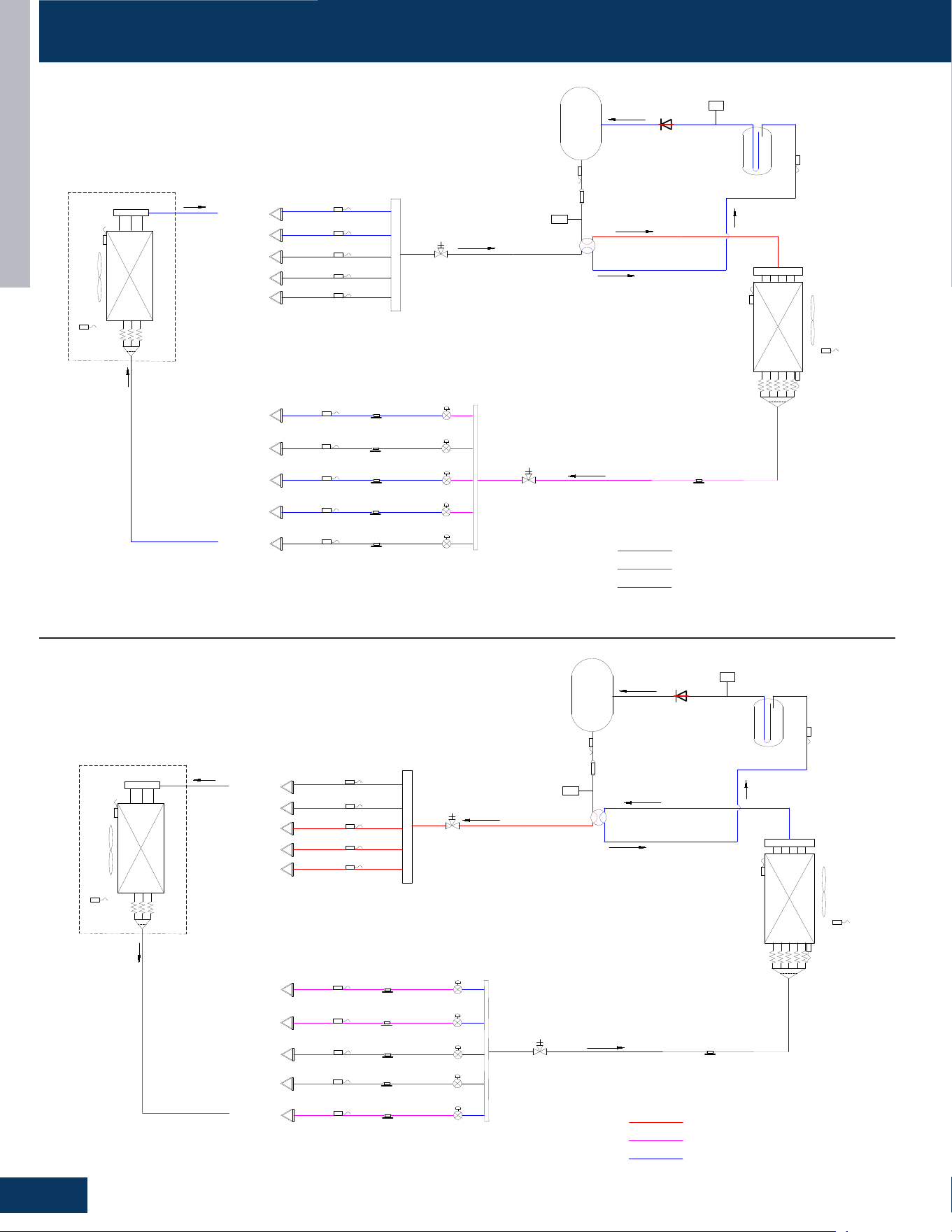
OUTDOOR UNITS
B32
ENGLISH
PIPING DIAGRAMS
5G42ED2BEA Cooling
High Pressure Swtich
Four Way Valve
4WV
Low Pressure Switch
LP
Gas-liquid
Separator
Gas Stop Valve
with
Service Port
Ø
15.88mm
(
5/8in.
)
Sensor
TC
FAN-OUT
Sensor
TA
Sensor
TE
Distributor
Liquid Stop Vavle
with
Service Port
Ø
9.52mm
(
3/8in.
)
PMV
B
Indoor Unit B
Sensor TC1
Sensor TC1
Indoor unit A
Indoor unit B
FAN-IN
Sensor
TAi
Sensor
TM
PMV
A
Indoor Unit A
High temperature,high pressure,gas
High temperature,high pressure,liquid
Low temperature,low pressure,gas/liquid
Liquid Pipe
Gas Pipe
Sensor
TC2
Sensor
TC2
Sensor
TS
LPS
HPS
Heat
Exchanger
Heat
Exchanger
Electronic Expansion Valve
Electrionc Expansion Valve
Filter
Filter
Filter
Compressor
INV
Sensor
TD
Silencer
HP
Sensor TC1
Indoor unit C
Sensor TC1
Indoor unit D
Sensor TC1
Indoor unit E
PMV
D
Indoor Unit D
PMV
C
Indoor Unit C
Sensor
TC2
Sensor
TC2
Electronic Expansion Valve
Electrionc Expansion Valve
Filter
Filter
PMV
E
Indoor Unit E
Sensor
TC2
Electrionc Expansion Valve
Filter
Single Way Valve
5G42ED2BEA Heating
High Pressure Swtich
Four Way Valve
4WV
Low Pressure Switch
LP
Gas-liquid
Separator
Gas Stop Valve
with
Service Port
Ø
15.88mm
(
5/8in.
)
Sensor
TC
FAN-OUT
Sensor
TA
Sensor
TE
Distributor
Liquid Stop Vavle
with
Service Port
Ø
9.52mm
(
3/8in.
)
PMV
B
Indoor Unit B
Sensor TC1
Sensor TC1
Indoor unit A
Indoor unit B
FAN-IN
Sensor
TAi
Sensor
TM
PMV
A
Indoor Unit A
High temperature,high pressure,gas
High temperature,high pressure,liquid
Low temperature,low pressure,gas/liquid
Liquid Pipe
Gas Pipe
Sensor
TC2
Sensor
TC2
Sensor
TS
LPS
HPS
Heat
Exchanger
Heat
Exchanger
Electronic Expansion Valve
Electrionc Expansion Valve
Filter
Filter
Filter
Compressor
INV
Sensor
TD
Silencer
HP
Single Way Valve
Sensor TC1
Indoor unit C
Sensor TC1
Indoor unit D
Sensor TC1
Indoor unit E
PMV
D
Indoor Unit D
PMV
C
Indoor Unit C
Sensor
TC2
Sensor
TC2
Electronic Expansion Valve
Electrionc Expansion Valve
Filter
Filter
PMV
E
Indoor Unit E
Sensor
TC2
Electrionc Expansion Valve
Filter
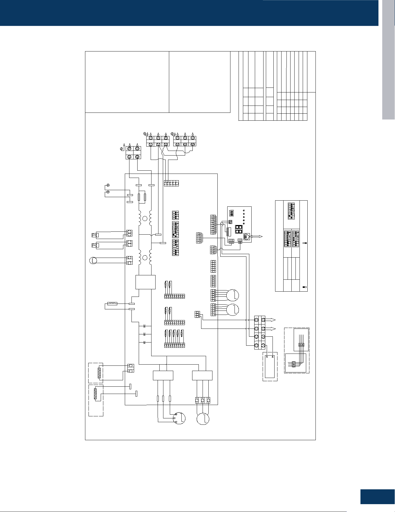
OUTDOOR UNITS
B33
ENGLISH
WIRING DIAGRAMS
2G18AD2BEA / 2G20ED2BEA
M
DC Fan motor
M
U1
V1
W1
Reactor
Compressor
CN16(Y)
CN17(G)
CN18(BL)
CN19(W)
M
M
EEV-A
EEV-B
LED1
LED2
LED3
LED4
LED5
CN21
Ta
Td
Te
L1
L2
1
2
3
1
2
3
CN5
CN4
CON9
CON8
CN8
CN23
Crankcase
heater
Base pan
heater
TC1-A
TC1-B
TC2-A
TC2-B
CN14
CN1
CN24
Power supply
CN12
HPS
LPS
CN13
4WV
B
W
B
W
R
Sensor
abbreviation
:
Tc
: Outdoor coil temperature sensor
Other abbreviation:
B
: Black,
BL
: Blue,
BR
: Brown,
G
: Green,
GRY
: Grey,
OR
: orange,
P
: Purple,
R
: Red,
W
: White,
Y/G
: Yellow/Green,
Y
: Yellow
LPS/HPS
: Low/high pressure switch
Note:
5.For the IDU and outdoor unit
OTA cable
,
it should be shielded
twisted pair cable type.
SW1
Display board
GRY
EEV
:electro expansion valve
EEV-A/B/C/D/E: Electro expansion valve
for indoor unit A/B/C/D/E
G/Y
G/Y
PE
CN60
L2
L20
L0
CN2
CN3
W
V
U
CN41
R
W
B
To indoor
unit B
To indoor
unit A
G
W
R
W
BL
R
Y
Tc
Ts
W
W
W
B
R
W
R
W
B
Ts
: Compressor suction temperature sensor
Ta
: Outdoor ambient temperature sensor
Td
: Compressor discharge temperature
sensor
Te
: Outdoor condenser defrosting coil
temperature sensor
Tc1
: Indoor gas pipe coil temperature
sensor for indoor unit or tank unit
Tc2
: Indoor liquid pipe coil temperature
sensor for indoor unit or tank unit
1.Dashed parts are optional.
2.Please refer to service manual to
get details of the DIP switches.
3.Do not change the DIP switches
setting without technical support.
4.The LED1-LED5 in the service
display board corresponds to the
communication status of indoor unit
A,B,C,D ,E,respectively.LED will not lit
if communication abnormal.
L1
B
A
CN26
W
To RJ45 device
CN10
BL
B
A
CN7
CN6
L1-OUT
L2-OUT
CN26
W
CN7
BL
RX
TX
RJ45
RJ45 connection
RJ45-2
RJ45-4
RJ45-5
RJ45-6
DEPOP
DEPOP
Main control panel
Display panel
C1
To indoor unit
BR
R
R
BR
C2
H1(A)
H2(B)
Central controller
A
B
FUSE1
DB1
+
-
E27
E28
E30
IPM1
IPM2
+
-
+
-
250V 20A
FUSE2
250V 20A
208/230V
230V
230V
230V
230V
230V
230V
230V
310V
12V
5V
15V
ON
OFF
SW5
SW6
SW7
ON
OFF
Means switch at ON position
Means switch at OFF position
Factory default DIP switches settings
:
Other details about the service information please refer to technical service mannual.
Factory default of main control board SW5 & SW7
SW5
SW7
SW5
2Q18FF2BAA1
2G18AD2BAA1
2Q20RT2BAA1
2G20EE2BAA1
Model
Model
ON
ON
ON
ON
OFF
ON
OFF
SW1-1
SW1-2
SW1-3
SW1-4
OFF
OFF
OFF
OFF
Centralized control address
SW6-1
SW6-2
SW6-3
SW6-4
OFF
OFF
OFF
OFF
Definition of main control board SW6
ON
OFF
OFF OFF
Indoor unit address group1
( NO.6-NO.10)
……
ON
ON
ON ON
Indoor unit address group15
( NO.76-NO.80)
Definition of Display Board SW1
Normal Operating(Default)
Manually Forced Heating
Manually Forced Cooling
Rated Operating
(
Fixed Speed
)
Time Defrost Valid
IDU&ODU Wiring Error Check
OFF
OFFON
OFF
OFF
OFF
ON
OFF
OFF
OFF
OFF
OFF
ON
Definition of Display Board SW1
Indoor unit address group0
( NO.1-NO.5)
(default)
0150574814
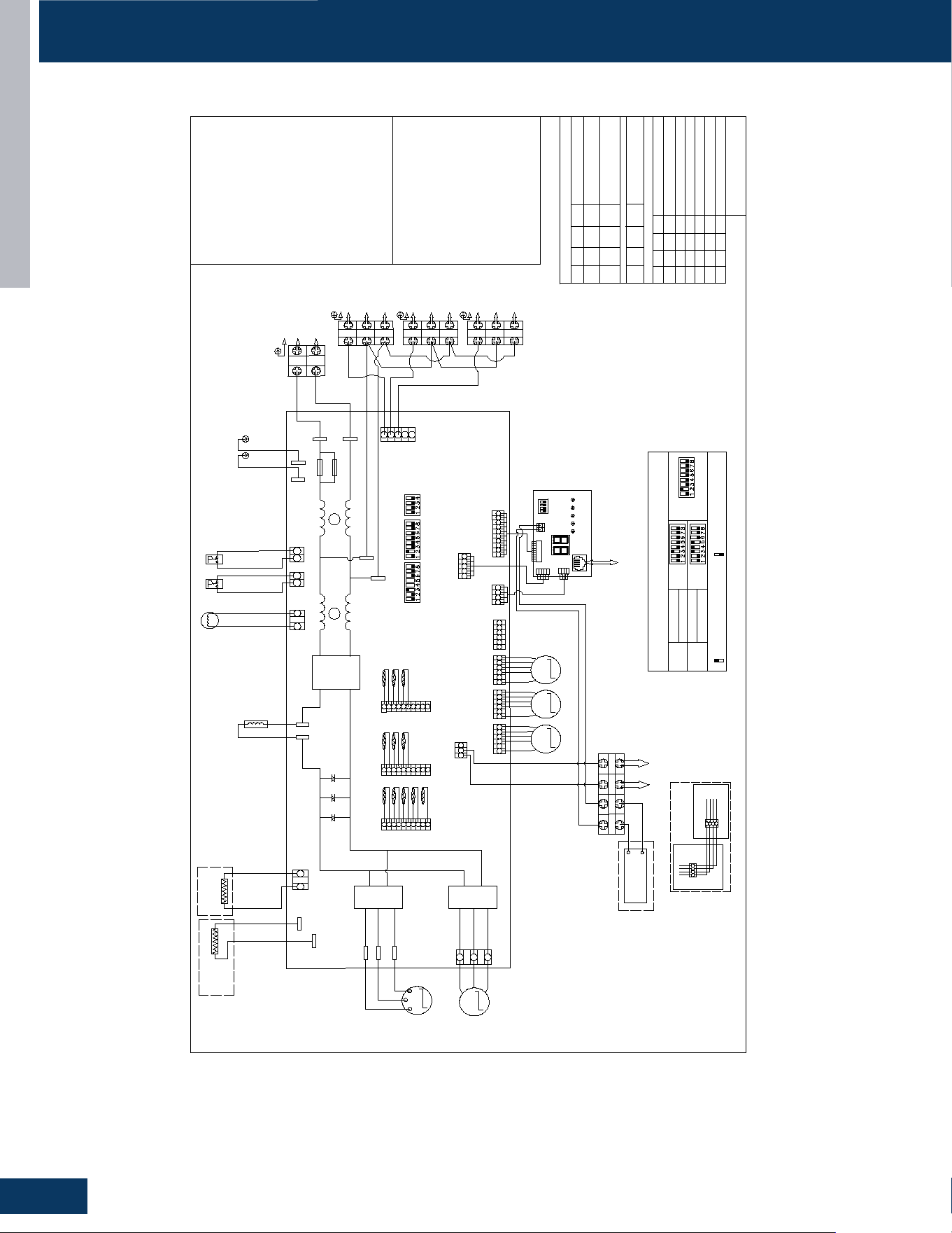
OUTDOOR UNITS
B34
ENGLISH
WIRING DIAGRAMS
3G24AD2BEA / 3G24ED2BEA
M
DC Fan motor
M
U1
V1
W1
Reactor
Compressor
CN16(Y)
CN17(G)
CN18(BL)
CN19(W)
M
M
M
EEV-A
EEV-B
EEV-C
LED1
LED2
LED3
LED4
LED5
CN21
Ta
Td
Te
L1
L2
1
2
3
1
2
3
1
2 3
CN5
CN4
CON9
CON8
CN8
CN23
Crankcase
heater
Base pan
heater
TC1-A
TC1-B
TC1-C
TC2-A
TC2-B
TC2-C
To indoor
unit C
CN14
CN1
CN24
Power supply
CN12
HPS
LPS
CN13
4WV
B
W
ON
OFF
B
W
R
Sensor
abbreviation
:
Tc
: Outdoor coil temperature sensor
Other abbreviation:
B
: Black,
BL
: Blue,
BR
: Brown,
G
: Green,
GRY
: Grey,
OR
: orange,
P
: Purple,
R
: Red,
W
: White,
Y/G
: Yellow/Green,
Y
: Yellow
LPS/HPS
: Low/high pressure switch
Note:
5.For the IDU and outdoor unit
OTA cable
,
it should be shielded
twisted pair cable type.
ON
OFF
Means switch at ON position
Means switch at OFF position
SW1
Display board
GRY
EEV
:electro expansion valve
EEV-A/B/C/D/E: Electro expansion valve
for indoor unit A/B/C/D/E
Factory default DIP switches settings
:
Other details about the service information please refer to technical service mannual.
Factory default of main control board SW5 & SW7
G/Y
G/Y
PE
CN60
L2
SW5
SW6
SW7
L20
L0
CN2
CN3
W
V
U
CN41
R
W
B
To indoor
unit B
To indoor
unit A
G
W
R
W
BL
R
Y
Tc
Ts
W
W
W
B
R
W
R
W
B
W
B
Ts
: Compressor suction temperature sensor
Ta
: Outdoor ambient temperature sensor
Td
: Compressor discharge temperature
sensor
Te
: Outdoor condenser defrosting coil
temperature sensor
Tc1
: Indoor gas pipe coil temperature
sensor for indoor unit or tank unit
Tc2
: Indoor liquid pipe coil temperature
sensor for indoor unit or tank unit
1.Dashed parts are optional.
2.Please refer to service manual to
get details of the DIP switches.
3.Do not change the DIP switches
setting without technical support.
4.The LED1-LED5 in the service
display board corresponds to the
communication status of indoor unit
A,B,C,D ,E,respectively.LED will not lit
if communication abnormal.
L1
B
A
CN26
W
To RJ45 device
CN10
BL
B
A
R
SW5
SW7
CN7
CN6
SW5
3Q24FF2BAA
3G24AD2BAA
3U24S3PS3HE
3G24EE2BAA
Model
Model
L1-OUT
L2-OUT
CN26
W
CN7
BL
RX
TX
RJ45
RJ45 connection
RJ45-2
RJ45-4
RJ45-5
RJ45-6
DEPOP
DEPOP
Main control panel
Display panel
C1
To indoor unit
BR
R
R
BR
C2
H1(A)
H2(B)
Central controller
A
B
FUSE1
DB1
+
-
E27
E28
E30
IPM1
IPM2
+
-
+
-
250V 20A
FUSE2
250V 20A
208/230V
230V
230V
230V
230V
230V
230V
230V
230V
310V
12V
5V
15V
ON
ON
ON
ON
OFF
ON
OFF
SW1-1
SW1-2
SW1-3
SW1-4
OFF
OFF
OFF
OFF
Centralized control address
SW6-1
SW6-2
SW6-3
SW6-4
OFF
OFF
OFF
OFF
Definition of main control board SW6
ON
OFF
OFF OFF
Indoor unit address group1
( NO.6-NO.10)
……
ON
ON
ON ON
Indoor unit address group15
( NO.76-NO.80)
Definition of Display Board SW1
Normal Operating(Default)
Manually Forced Heating
Manually Forced Cooling
Rated Operating
(
Fixed Speed
)
Time Defrost Valid
IDU&ODU Wiring Error Check
OFF
OFFON
OFF
OFF
OFF
ON
OFF
OFF
OFF
OFF
OFF
ON
Definition of Display Board SW1
Indoor unit address group0
( NO.1-NO.5)
(default)
0150574815
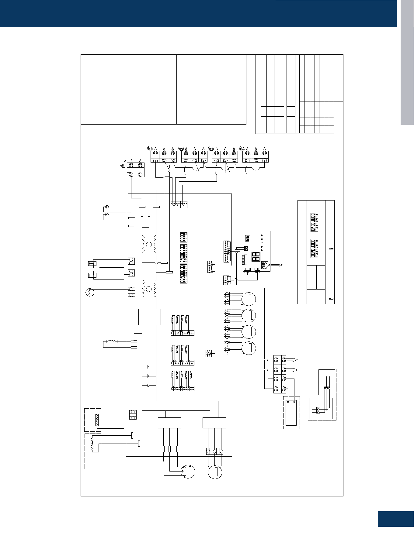
OUTDOOR UNITS
B35
ENGLISH
WIRING DIAGRAMS
4G36AD2BEA
M
DC Fan motor
M
U1
V1
W1
Reactor
Compressor
CN16(Y)
CN17(G)
CN18(BL)
CN19(W)
M
M
M
EEV-A
EEV-B
EEV-C
LED1
LED2
LED3
LED4
LED5
CN21
Ta
Td
Te
L1
L2
1
2
3
1
2
3
1
2 3
CN5
CN4
CON9
CON8
CN8
CN23
Crankcase
heater
Base pan
heater
TC1-A
TC1-B
TC1-C
TC2-A
TC2-B
TC2-C
To indoor
unit C
CN14
CN1
CN24
Power supply
CN12
HPS
LPS
CN13
4WV
B
W
B
W
R
Sensor
abbreviation
:
Tc
: Outdoor coil temperature sensor
Other abbreviation:
B
: Black,
BL
: Blue,
BR
: Brown,
G
: Green,
GRY
: Grey,
OR
: orange,
P
: Purple,
R
: Red,
W
: White,
Y/G
: Yellow/Green,
Y
: Yellow
LPS/HPS
: Low/high pressure switch
Note:
5.For the IDU and outdoor unit
OTA cable
,
it should be shielded
twisted pair cable type.
ON
ON
ON
ON
OFF
ON
OFF
SW1-1
SW1-2
SW1-3
SW1-4
OFF
OFF
OFF
OFF
Centralized control address
SW6-1
SW6-2
SW6-3
SW6-4
OFF
OFF
OFF
OFF
Definition of main control board SW6
ON
OFF
OFF OFF
Indoor unit address group1
( NO.6-NO.10)
……
ON
ON
ON ON
Indoor unit address group15
( NO.76-NO.80)
Definition of Display Board SW1
Normal Operating(Default)
Manually Forced Heating
Manually Forced Cooling
Rated Operating
(
Fixed Speed
)
Time Defrost Valid
IDU&ODU Wiring Error Check
OFF
OFFON
OFF
OFF
OFF
ON
OFF
OFF
OFF
OFF
OFF
ON
SW1
Display board
GRY
EEV
:electro expansion valve
EEV-A/B/C/D/E: Electro expansion valve
for indoor unit A/B/C/D/E
Definition of Display Board SW1
G/Y
G/Y
PE
CN60
L2
L20
L0
CN2
CN3
W
V
U
CN41
R
W
B
To indoor
unit B
To indoor
unit A
Indoor unit address group0
( NO.1-NO.5)
(default)
G
W
R
W
BL
R
Y
Tc
Ts
W
W
W
B
R
W
R
W
B
W
B
Ts
: Compressor suction temperature sensor
Ta
: Outdoor ambient temperature sensor
Td
: Compressor discharge temperature
sensor
Te
: Outdoor condenser defrosting coil
temperature sensor
Tc1
: Indoor gas pipe coil temperature
sensor for indoor unit or tank unit
Tc2
: Indoor liquid pipe coil temperature
sensor for indoor unit or tank unit
1.Dashed parts are optional.
2.Please refer to service manual to
get details of the DIP switches.
3.Do not change the DIP switches
setting without technical support.
4.The LED1-LED5 in the service
display board corresponds to the
communication status of indoor unit
A,B,C,D ,E,respectively.LED will not lit
if communication abnormal.
L1
B
A
CN26
W
To RJ45 device
CN10
BL
B
A
R
CN7
CN6
L1-OUT
L2-OUT
CN26
W
CN7
BL
RX
TX
RJ45
RJ45 connection
RJ45-2
RJ45-4
RJ45-5
RJ45-6
DEPOP
DEPOP
Main control panel
Display panel
C1
To indoor unit
BR
R
R
BR
C2
H1(A)
H2(B)
Central controller
A
B
FUSE1
DB1
+
-
E27
E28
E30
IPM1
IPM2
+
-
+
-
250V 20A
FUSE2
250V 20A
208/230V
230V
230V
230V
230V
230V
230V
230V
230V
310V
12V
5V
0150574816
1
2 3
To indoor
unit D
230V
R
15V
ON
ON
Means switch at ON position
Means switch at OFF position
Factory default DIP switches settings
:
Other details about the service information please refer to technical service mannual.
Factory default of main control board SW5 & SW7
SW5
SW7
4Q36FF2BAA
4G36AD2BAA
Model
ON
OFF
SW5
SW6
SW7
TC1-D
TC2-D
M
EEV-D
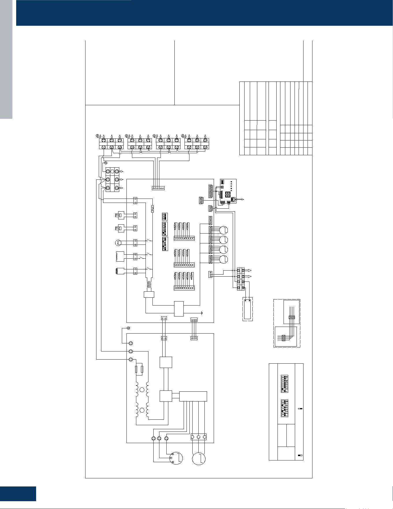
OUTDOOR UNITS
B36
ENGLISH
WIRING DIAGRAMS
4G36ED2BEA
Sensor
abbreviation
:
Tc
: Outdoor coil temperature sensor
Other abbreviation:
B
: Black,
BL
: Blue,
BR
: Brown,
G
: Green,
GRY
: Grey,
OR
: orange,
P
: Purple,
R
: Red,
W
: White,
Y/G
: Yellow/Green,
Y
: Yellow
LPS/HPS
: Low/high pressure switch
Note:
5.For the IDU and outdoor unit
OTA cable,it should be shielded
twisted pair cable type.
ON
ON
ON
ON
OFF
ON
OFF
SW1-1
SW1-2
SW1-3
SW1-4
OFF
OFF
OFF
OFF
Centralized control address
SW6-1
SW6-2
SW6-3
SW6-4
OFF
OFF
OFF
OFF
Definition of main control board SW6
ON
OFF
OFF OFF
Indoor unit address group1
( NO.6-NO.10)
……
ON
ON
ON ON
Indoor unit address group15
( NO.76-NO.80)
Definition of Display Board SW1
Normal Operating(Default)
Manually Forced Heating
Manually Forced Cooling
Rated Operating
(
Fixed Speed
)
Time Defrost Valid
IDU&ODU Wiring Error Check
OFF
OFFON
OFF
OFF
OFF
ON
OFF
OFF
OFF
OFF
OFF
ON
EEV
:electro expansion valve
EEV-A/B/C/D/E: Electro expansion valve
for indoor unit A/B/C/D/E
Definition of Displ
a
y Board SW1
Indoor unit address group0
( NO.1-NO.5)
(default)
Ts
: Compressor suction temperature sensor
Ta
: Outdoor ambient temperature sensor
Td
: Compressor discharge temperature
sensor
Te
: Outdoor condenser defrosting coil
temperature sensor
Tc1
: Indoor gas pipe coil temperature
sensor for indoor unit or tank unit
Tc2
: Indoor liquid pipe coil temperature
sensor for indoor unit or tank unit
1.Dashed parts are optional.
2.Please refer to service manual to
get details of the DIP switches.
3.Do not change the DIP switches
setting without technical support.
4.The LED1-LED5 in the service
display board corresponds to the
communication status of indoor unit
A,B,C,D ,E,respectively.LED will not lit
if communication abnormal.
0150574817
M
DC Fan motor
M
U
V
W
Compressor
CN17(G)
CN18(BL)
CN19(W)
M
M
M
EEV-B
EEV-C
LED1
LED2
LED3
LED4
LED5
CN21
1
2
3
1
2
3
1
2 3
CN8
CN23
To indoor
unit C
B
W
R
SW1
Displ
a
y board
CN2
CN3
W
V
U
CN41
R
W
B
To indoor
unit B
To indoor
unit A
EEV-D
B
A
CN26
To RJ45 device
B
A
1
2 3
To indoor
unit D
CN7
CN6
L1
L2
Power supply
G
Inverter
Board
EARTH
W
B
Y/G
Y/G
W
B
CN2
W
CN3
W
CN34
R
R
B
R
W
CN9
W
B
W
CN28
G
Crankcase
heater
Base pan
heater
CN4
B
CN5
W
4WV
W
B
HPS
LPS
CN12
R
CN13
W
Ta
Td
Te
TC1-A
TC1-B
TC1-C
TC2-A
TC2-B
TC2-C
CN14
CN1
CN24
BL
R
Y
Tc
Ts
TC1-D
TC2-D
ON
OFF
Main control Board
M
EEV-A
CN16(Y)
CN10
BL
W
W
W
CN4
R
BR
R
WW
BL
W
W
B
R
B
B
B
W
W
W
R
R
R
CN20(B)
6.3A 250V
FUSE
CN26
W
CN7
BL
RX
TX
RJ45
RJ45 connection
RJ45-2
RJ45-4
RJ45-5
RJ45-6
DEPOP
DEPOP
Main control panel
Display panel
C1
To indoor unit
BR
R
BR
R
CN2
R
H1
(
A)
L1
L2
H2
(
B)
C2
Central controller
A
B
K2
K3
K4
K5
LX1
BD1
+
-
T1
+
-
FUSE1
250V 30A
FUSE2
250V 30A
MCU
PFC
IPM
230V
230V
230V
230V
208/230V
15V
12V
5V
230V
230V
230V
230V
230V
5V
12V
ON
ON
Means switch at ON position
Means switch at OFF position
Factory default DIP switches settings
:
Other details about the service information please refer to technical service mannual.
Factory default of main control board SW5 & SW7
SW5
SW7
4Q36RT2BEA1
4G36ED2BEA1
Model
SW5
SW6
SW7
1
2 3 4 5
6
7 8
1 2 3 4 5
6
7 8 1 2 3 4
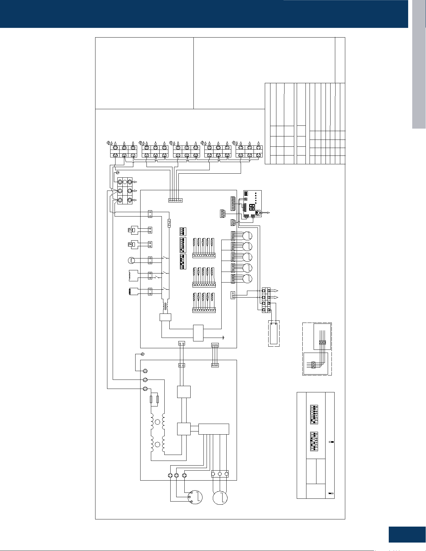
OUTDOOR UNITS
B37
ENGLISH
WIRING DIAGRAMS
5G42ED2BEA
Sensor
abbreviation
:
Tc
: Outdoor coil temperature sensor
Other abbreviation:
B
: Black,
BL
: Blue,
BR
: Brown,
G
: Green,
GRY
: Grey,
OR
: orange,
P
: Purple,
R
: Red,
W
: White,
Y/G
: Yellow/Green,
Y
: Yellow
LPS/HPS
: Low/high pressure switch
Note:
5.For the IDU and outdoor unit
OTA cable,it should be shielded
twisted pair cable type.
ON
ON
ON
ON
OFF
ON
OFF
SW1-1
SW1-2
SW1-3
SW1-4
OFF
OFF
OFF
OFF
Centralized control address
SW6-1
SW6-2
SW6-3
SW6-4
OFF
OFF
OFF
OFF
Definition of main control board SW6
ON
OFF
OFF OFF
Indoor unit address group1
( NO.6-NO.10)
……
ON
ON
ON ON
Indoor unit address group15
( NO.76-NO.80)
Definition of Display Board SW1
Normal Operating(Default)
Manually Forced Heating
Manually Forced Cooling
Rated Operating
(
Fixed Speed
)
Time Defrost Valid
IDU&ODU Wiring Error Check
ON
ON
Means switch at ON position
Means switch at OFF position
OFF
OFFON
OFF
OFF
OFF
ON
OFF
OFF
OFF
OFF
OFF
ON
EEV
:electro expansion valve
EEV-A/B/C/D/E: Electro expansion valve
for indoor unit A/B/C/D/E
Factory default DIP switches settings
:
Other details about the service information please refer to technical service mannual.
Factory default of main control board SW5 & SW7
Definition of Displ
a
y Board SW1
Indoor unit address group0
( NO.1-NO.5)
(default)
Ts
: Compressor suction temperature sensor
Ta
: Outdoor ambient temperature sensor
Td
: Compressor discharge temperature
sensor
Te
: Outdoor condenser defrosting coil
temperature sensor
Tc1
: Indoor gas pipe coil temperature
sensor for indoor unit or tank unit
Tc2
: Indoor liquid pipe coil temperature
sensor for indoor unit or tank unit
1.Dashed parts are optional.
2.Please refer to service manual to
get details of the DIP switches.
3.Do not change the DIP switches
setting without technical support.
4.The LED1-LED5 in the service
display board corresponds to the
communication status of indoor unit
A,B,C,D ,E,respectively.LED will not lit
if communication abnormal.
0150577569
SW5
SW7
5Q42RT2BEA1
5G42ED2BEA1
Model
M
DC Fan motor
M
U
V
W
Compressor
CN17(G)
CN18(BL)
CN19(W)
M
M
M
EEV-B
EEV-C
LED1
LED2
LED3
LED4
LED5
CN21
1
2
3
1
2
3
1
2 3
CN8
CN23
To indoor
unit C
B
W
R
SW1
Displ
a
y board
CN2
CN3
W
V
U
CN41
R
W
B
To indoor
unit B
To indoor
unit A
EEV-D
B
A
CN26
To RJ45 device
B
A
1
2 3
To indoor
unit D
CN7
CN6
L1
L2
Power supply
G
Inverter
Board
EARTH
W
B
Y/G
Y/G
W
B
CN2
W
CN3
W
CN34
R
R
B
R
W
CN9
W
B
W
CN28
G
Crankcase
heater
Base pan
heater
CN4
B
CN5
W
4WV
W
B
HPS
LPS
CN12
R
CN13
W
Ta
Td
Te
TC1-A
TC1-B
TC1-C
TC2-A
TC2-B
TC2-C
CN14
CN1
CN24
BL
R
Y
Tc
Ts
TC1-D
TC2-D
ON
OFF
SW5
SW6
SW7
Main control Board
M
EEV-A
CN16(Y)
CN10
BL
W
W
W
CN4
R
BR
R
WW
BL
W
W
B
R
B
B
B
W
W
W
R
R
R
TC1-E
TC2-E
CN20(B)
M
EEV-E
1
2 3
To indoor
unit E
B
W
R
6.3A 250V
FUSE
CN26
W
CN7
BL
RX
TX
RJ45
RJ45 connection
RJ45-2
RJ45-4
RJ45-5
RJ45-6
DEPOP
DEPOP
Main control panel
Display panel
1 2 3 4 5
6
7 8
1 2 3 4 5
6
7 8 1 2 3 4
C1
To indoor unit
BR
R
BR
R
CN2
R
H1
(
A)
L1
L2
H2
(
B)
C2
Central controller
A
B
K2
K3
K4
K5
LX1
BD1
+
-
T1
+
-
FUSE1
250V 30A
FUSE2
250V 30A
MCU
PFC
IPM
230V
230V
230V
230V
230V
208/230V
15V
12V
5V
230V
230V
230V
230V
230V
5V
12V
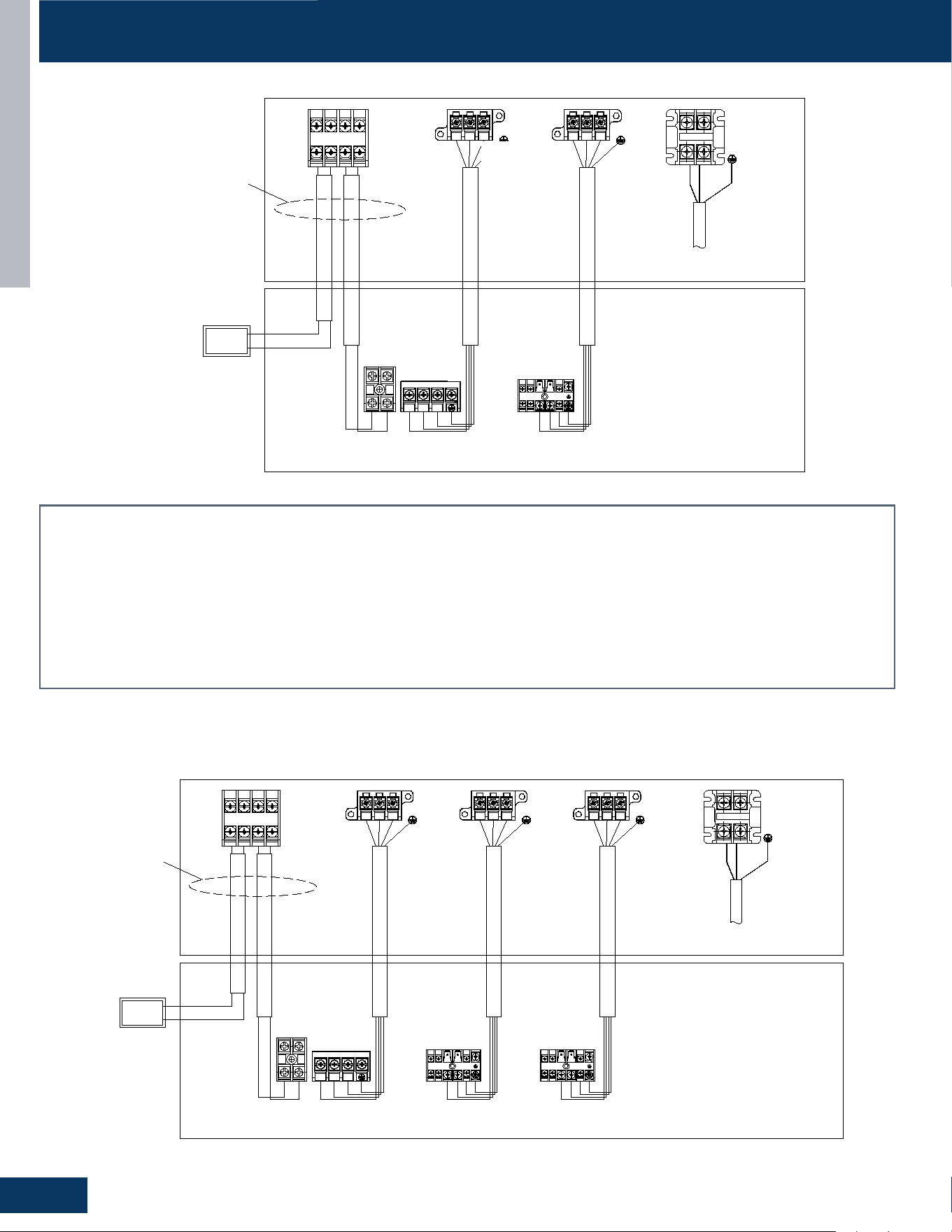
OUTDOOR UNITS
B38
ENGLISH
OUTDOOR/INDOOR WIRING CONNECTIONS
2G18AD2BEA / 2G20ED2BEA
H1(A)
C1 C2
H2(B)
1
L1
L2
Power Supply
1Ph,208
/230V
@1
2 3 1 2 3
Outdoor Unit
H1
H2
B
A
Central
Controller
A B
Indoor Unit
@3
@4
@2 @2
Power supply cable, 3*6mm²
Communication cable for indoor unit and outdoor unit,4*2.5mm²
Caution
:
①
The OTA communication cable should be shielded twisted pair type,
and need to make the cable's shielded layer connect to earth or the unit
shell which connect to earth (indoor side or outdoor side).
② There should be independent pipeline for communication wire.
③ The distance between OTA communication cable and the power supply
cable should be at least 10cm.
④ Ensure specifically that there is an earth leakage breaker (ELB)
installed for both the outdoor and indoor unit.
⑤ If the installation is already fitted with an earth leakage breaker (ELB),
ensure that its rated current is large enough to withstand the current of the
units (both outdoor and indoor).
@3:
@1:
@2:
Communication cable for central controller, wire specification to
refer to wired controller manual and real installation length.
@4:
Communication cable for OTA,one of the indoor unit and outdoor
unit,2*0.75mm²
2U机型
Indoor Unit --DUCT Indoor Unit --Cassette
H1
H2
1
2
3
OTA
One of the Indoor Unit
Central Controller
These c
ommunication
cable should be shielded
twisted pair type.
1 2
3
3G24AD2BEA / 3G24ED2BEA / 3G24ED2BEA
H1(A)
C1 C2
H2(B)
1
L1
L2
Power Supply
1Ph,208
/230V
@1
2 3 1 2 31 2 3
Outdoor Unit
H1
H2
B
A
Central
Controller
A B
C
Indoor Unit
@3
@4
@2 @2 @2
Power supply cable, 3*6mm²
Communication cable for indoor unit and outdoor unit,4*2.5mm²
Caution
:
①
The OTA communication cable should be shielded twisted pair type,
and need to make the cable's shielded layer connect to earth or the unit
shell which connect to earth (indoor side or outdoor side).
②
There should be independent pipeline for communication wire.
③
The distance between OTA communication cable and the power supply
cable should be at least 10cm.
④
Ensure specifically that there is an earth leakage breaker (ELB)
installed for both the outdoor and indoor unit.
⑤
If the installation is already fitted with an earth leakage breaker (ELB),
ensure that its rated current is large enough to withstand the current of the
units (both outdoor and indoor).
@3:
@1:
@2:
Communication cable for central controller, wire specification to
refer to wired controller manual and real installation length.
@4:
Communication cable for OTA,one of the indoor unit and outdoor
unit,2*0.75mm²
3U机型
H1
H2
1
2
3
Indoor Unit --DUCT Indoor Unit --Cassette
H1
H2
1
2
3
Indoor Unit --Console
OTA
One of the Indoor Unit
Central Controller
1 2
3
These c
ommunication
cable should be shielded
twisted pair type.
Caution:
1. The OTA communication cable should be shielded twisted pair type, and need to make the cable’s shielded layer connect to earth or the unit shell which
connect to earth (indoor side or outdoor side).
2. There should be independent pipeline for communication wire.
3. The distance between OTA communication cable and the power supply cable should be at least 10cm.
4. EnsurespecicallythereisaGroundFaultDetector(GFI)installedforboththeoutdoorandindoorunit.
5. IftheinstallationisalreadyttedwithaGFI,ensurethatitsratedcurrentislargeenoughtowithstandthecurrentoftheunits(bothoutdoorandindoor).
@1 Power supply cable, 3*6mm²
@2 Communication cable for indoor unit and outdoor unit,4*2.5mm²
@3Communicationcableforcentralcontroller,wirespecicationtorefertowiredcontrollermanualandrealinstallationlength.
@4 Communication cable for OTA,one of the indoor unit and outdoor unit,2*0.75mm²
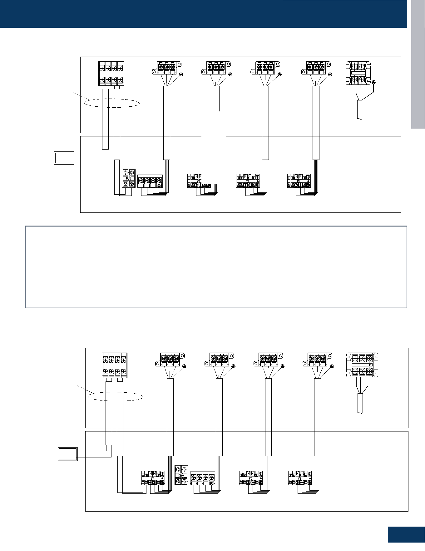
OUTDOOR UNITS
B39
ENGLISH
OUTDOOR/INDOOR WIRING CONNECTIONS
4G36AD2BEA
H1(A)
C1 C2
H2(B)
1
L1
L2
Power Supply
1Ph,208
/230V
@1
2 3 1 2 31 2 3
Outdoor Unit
H1
H2
B
A
Central
Controller
A B
C
Indoor Unit
@3
@4
@2 @2 @2
Power supply cable, 3*6mm²
Communication cable for indoor unit and outdoor unit,4*2.5mm²
Caution
:
①
The OTA communication cable should be shielded twisted pair type,
and need to make the cable's shielded layer connect to earth or the unit
shell which connect to earth (indoor side or outdoor side).
②
There should be independent pipeline for communication wire.
③
The distance between OTA communication cable and the power supply
cable should be at least 10cm.
④
Ensure specifically that there is an earth leakage breaker (ELB)
installed for both the outdoor and indoor unit.
⑤
If the installation is already fitted with an earth leakage breaker (ELB),
ensure that its rated current is large enough to withstand the current of the
units (both outdoor and indoor).
@3:
@1:
@2:
Communication cable for central controller, wire specification to
refer to wired controller manual and real installation length.
@4:
Communication cable for OTA,one of the indoor unit and outdoor
unit,2*0.75mm²
常温4U机型
H1
H2
1
2
3
Indoor Unit --DUCT Indoor Unit --Cassette
H1
H2
1
2
3
Indoor Unit --Console
OTA
One of the Indoor Unit
Central Controller
1 2 3
D
@2
H1
H2
1
2
3
Indoor Unit --Highwall
1 2
3
These c
ommunication
cable should be shielded
twisted pair type.
4G36ED2BEA
1
L1
L2
Power Supply
1Ph,208
/230V
@1
2 3 1 2 31 2 3 1 2 3
Outdoor Unit
H1
H2
A B
C
D
Indoor Unit
@4
@2 @2 @2@2
Power supply cable, 3*6mm²
Communication cable for indoor unit and outdoor unit,4*2.5mm²
Caution
:
①
The OTA communication cable should be shielded twisted pair type,
and need to make the cable's shielded layer connect to earth or the unit
shell which connect to earth (indoor side or outdoor side).
②
There should be independent pipeline for communication wire.
③
The distance between OTA communication cable and the power supply
cable should be at least 10cm.
④
Ensure specifically that there is an earth leakage breaker (ELB)
installed for both the outdoor and indoor unit.
⑤
If the installation is already fitted with an earth leakage breaker (ELB),
ensure that its rated current is large enough to withstand the current of the
units (both outdoor and indoor).
@3:
@1:
@2:
Communication cable for central controller, wire specification to
refer to wired controller manual and real installation length.
@4:
Communication cable for OTA,one of the indoor unit and outdoor
unit,2*0.75mm²
4U低温机型
H1
H2
1
2
3
Indoor Unit --Cassette Indoor Unit --DUCT
H1
H2
1
2
3
H1
H2
1
2
3
Indoor Unit --Console Indoor Unit --Console
B
A
Central
Controller
@3
OTA
One of the Indoor Unit
Central Controller
H1(A)
C1 C2
H2(B)
These c
ommunication
cable should be shielded
twisted pair type.
Caution:
1. The OTA communication cable should be shielded twisted pair type, and need to make the cable’s shielded layer connect to earth or the unit shell which
connect to earth (indoor side or outdoor side).
2. There should be independent pipeline for communication wire.
3. The distance between OTA communication cable and the power supply cable should be at least 10cm.
4. EnsurespecicallythereisaGroundFaultDetector(GFI)installedforboththeoutdoorandindoorunit.
5. IftheinstallationisalreadyttedwithaGFI,ensurethatitsratedcurrentislargeenoughtowithstandthecurrentoftheunits(bothoutdoorandindoor).
@1 Power supply cable, 3*6mm²
@2 Communication cable for indoor unit and outdoor unit,4*2.5mm²
@3Communicationcableforcentralcontroller,wirespecicationtorefertowiredcontrollermanualandrealinstallationlength.
@4 Communication cable for OTA,one of the indoor unit and outdoor unit,2*0.75mm²
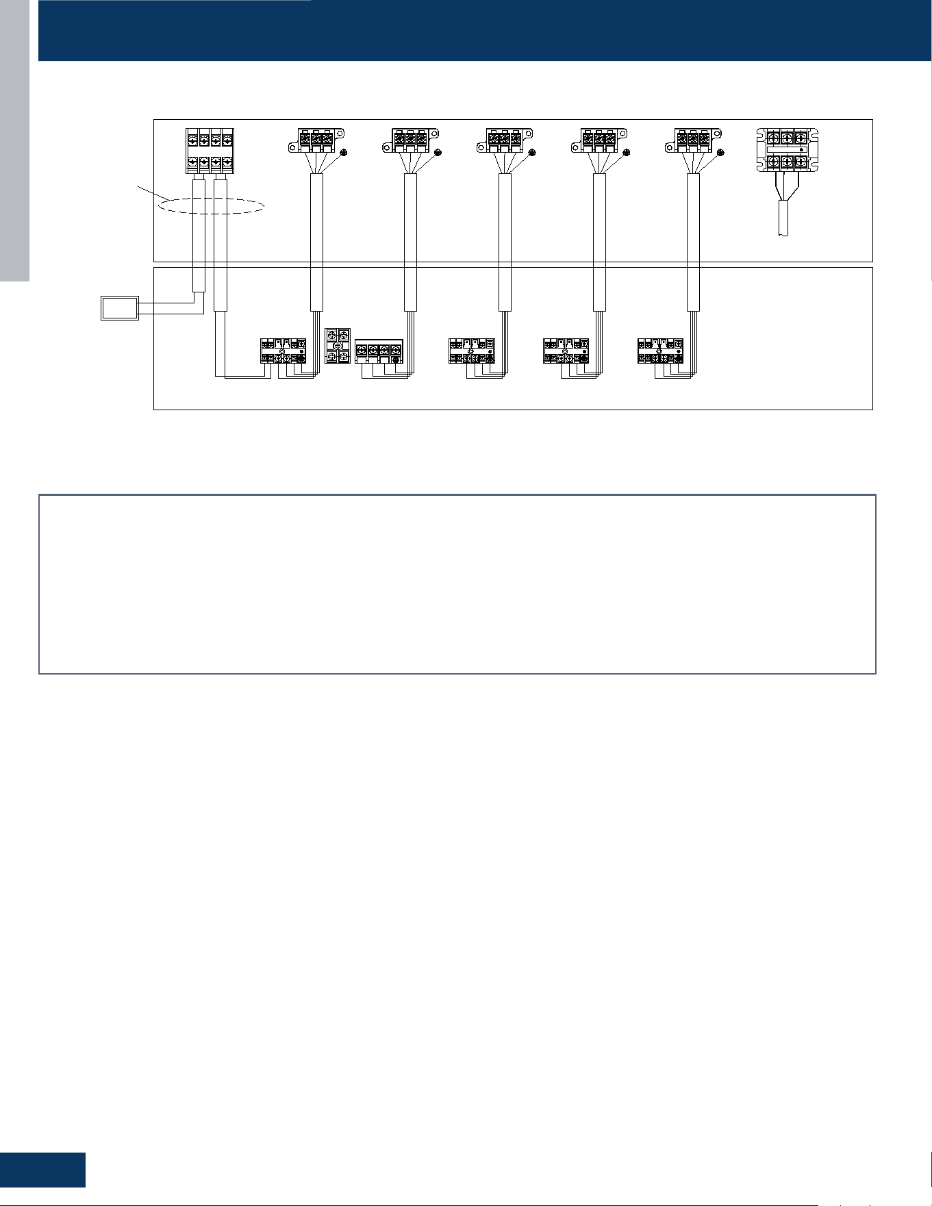
OUTDOOR UNITS
B40
ENGLISH
OUTDOOR/INDOOR WIRING CONNECTIONS
5G42ED2BEA
1
L1
L2
Power Supply
1Ph,208
/230V
@1
2 3 1 2 3 1 2 31 2 3 1 2 3
Outdoor Unit
H1
H2
A B
C
D
E
Indoor Unit
@4
@2 @2 @2@2 @2
Power supply cable, 3*6mm²
Communication cable for indoor unit and outdoor unit,4*2.5mm²
Caution
:
①
The OTA communication cable should be shielded twisted pair type,
and need to make the cable's shielded layer connect to earth or the unit
shell which connect to earth (indoor side or outdoor side).
②
There should be independent pipeline for communication wire.
③
The distance between OTA communication cable and the power supply
cable should be at least 10cm.
④
Ensure specifically that there is an earth leakage breaker (ELB)
installed for both the outdoor and indoor unit.
⑤
If the installation is already fitted with an earth leakage breaker (ELB),
ensure that its rated current is large enough to withstand the current of the
units (both outdoor and indoor).
@3:
@1:
@2:
Communication cable for central controller, wire specification to
refer to wired controller manual and real installation length.
@4:
Communication cable for OTA,one of the indoor unit and outdoor
unit,2*0.75mm²
5U机型
H1
H2 1
2
3
Indoor Unit --Cassette Indoor Unit --DUCT
H1
H2 1
2
3
H1
H2 1
2
3
H1
H2 1
2
3
Indoor Unit --Console Indoor Unit --Console
Indoor Unit --Highwall
B
A
Central
Controller
@3
OTA
One of the Indoor Unit
Central Controller
H1(A)
C1 C2
H2(B)
These c
ommunication
cable should be shielded
twisted pair type.
Caution:
1. The OTA communication cable should be shielded twisted pair type, and need to make the cable’s shielded layer connect to earth or the unit shell which
connect to earth (indoor side or outdoor side).
2. There should be independent pipeline for communication wire.
3. The distance between OTA communication cable and the power supply cable should be at least 10cm.
4. EnsurespecicallythereisaGroundFaultDetector(GFI)installedforboththeoutdoorandindoorunit.
5. IftheinstallationisalreadyttedwithaGFI,ensurethatitsratedcurrentislargeenoughtowithstandthecurrentoftheunits(bothoutdoorandindoor).
@1 Power supply cable, 3*6mm²
@2 Communication cable for indoor unit and outdoor unit,4*2.5mm²
@3Communicationcableforcentralcontroller,wirespecicationtorefertowiredcontrollermanualandrealinstallationlength.
@4 Communication cable for OTA,one of the indoor unit and outdoor unit,2*0.75mm²

HIGHWALL
C1
ENGLISH
HIGHWALL
TABLE OF CONTENTS
COMPONENTS .......................................................................................................................................................................C2
Component Overview ................................................................................................................................ C2, C3, C4, C8, C9,
Terminal Block ................................................................................................................................................................ C5, C10
Display .........................................................................................................................................................................C5, C10
Ambient Temperature Sensor ......................................................................................................................................C5, C10
Piping Temperature Sensor ..........................................................................................................................................C5, C10
Louver Stepper Motors .........................................................................................................................C6, C7, C11, C12, C13
Fan Motor ............................................................................................................................................... C6, C7, C11, C12, C13
Emergency Button ................................................................................................................................. C6, C7, C11, C12, C13
Jumper Wire Settings ..................................................................................................................................... C6, C7, C12, C13
PCB Overview ...................................................................................................................................................................... C14
WIRING DIAGRAM ................................................................................................................................................................. C15
GS07WB2BEA
GS09WB2BEA
GS12WB2BEA
GS15WB2BEA
GS18WB2BEA
GS24WB2BEA
GS09WP2BEA
GS12WP2BEA
GS18WP2BEA
GS24WP2BEA
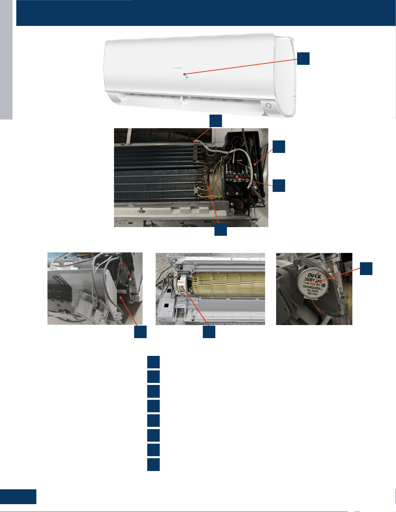
COMPONENTS
HIGHWALL
C2
ENGLISH
INDOOR UNITS
ENGLISH
,QGRRU&RPSRQHQW,GHQWLƭFDWLRQ
COMPONENTS
1
2
3
4
5
6
7
6
2
5
4
3
7
1
8
Ambient Temperature Sensor
Display Panel
Fan Motor
Louver Motors
Power Control Board(PCB)
Piping Temperature Sensor
Terminal Block
8
R454B Leakage sensor
INDOOR UNITS
ENGLISH
,QGRRU&RPSRQHQW,GHQWLƭFDWLRQ
COMPONENTS
1
2
3
4
5
6
7
6
2
5
4
3
7
1
8
Ambient Temperature Sensor
Display Panel
Fan Motor
Louver Motors
Power Control Board(PCB)
Piping Temperature Sensor
Terminal Block
8
R454B Leakage sensor
INDOOR UNITS
ENGLISH
,QGRRU&RPSRQHQW,GHQWLƭFDWLRQ
COMPONENTS
1
2
3
4
5
6
7
6
2
5
4
3
7
1
8
Ambient Temperature Sensor
Display Panel
Fan Motor
Louver Motors
Power Control Board(PCB)
Piping Temperature Sensor
Terminal Block
8
R454B Leakage sensor
2
1
4
2
5
7
3
6
8
5
1
7
6
8 3
4
Ambient Temperature Sensor
Display Panel
Fan Motor
Louver Motors
Power Control Board (PCB)
Piping Temperature Sensor
Terminal Block
R454B Leakage Sensor
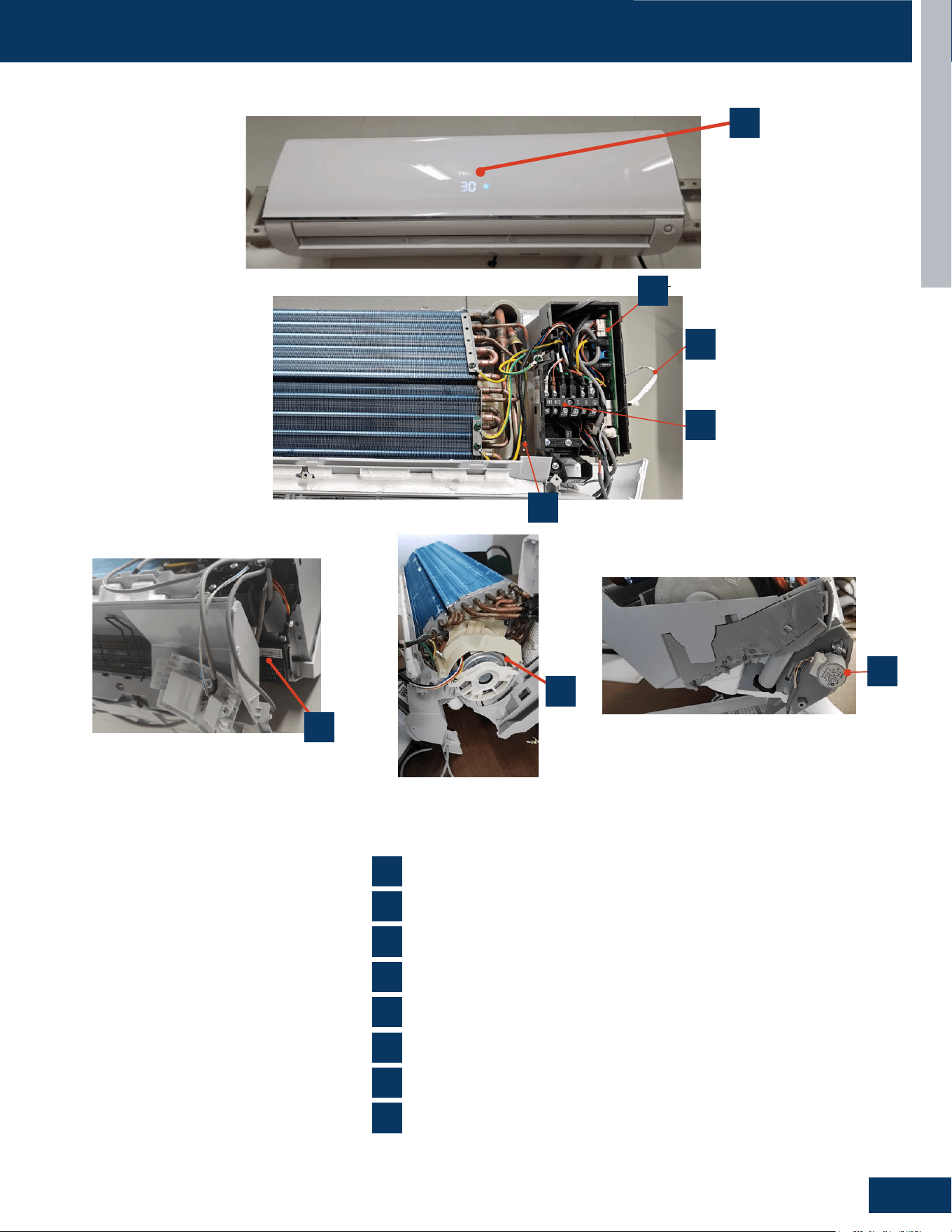
COMPONENTS
HIGHWALL
C3
ENGLISH
INDOOR UNITS
ENGLISH
,QGRRU&RPSRQHQW,GHQWLƭFDWLRQ
COMPONENTS
1
2
3
4
5
6
7
4
3
8
Ambient Temperature Sensor
Display Panel
Fan Motor
Louver Motors
Power Control Board (PCB)
Piping Temperature Sensor
Terminal Block
R454B Leak sensor
8
5
7
1
6
2
QS18WP2BEA
INDOOR UNITS
ENGLISH
,QGRRU&RPSRQHQW,GHQWLƭFDWLRQ
COMPONENTS
1
2
3
4
5
6
7
4
3
8
Ambient Temperature Sensor
Display Panel
Fan Motor
Louver Motors
Power Control Board (PCB)
Piping Temperature Sensor
Terminal Block
R454B Leak sensor
8
5
7
1
6
2
QS18WP2BEA
INDOOR UNITS
ENGLISH
,QGRRU&RPSRQHQW,GHQWLƭFDWLRQ
COMPONENTS
1
2
3
4
5
6
7
4
3
8
Ambient Temperature Sensor
Display Panel
Fan Motor
Louver Motors
Power Control Board (PCB)
Piping Temperature Sensor
Terminal Block
R454B Leak sensor
8
5
7
1
6
2
QS18WP2BEA
INDOOR UNITS
ENGLISH
,QGRRU&RPSRQHQW,GHQWLƭFDWLRQ
COMPONENTS
1
2
3
4
5
6
7
4
3
8
Ambient Temperature Sensor
Display Panel
Fan Motor
Louver Motors
Power Control Board (PCB)
Piping Temperature Sensor
Terminal Block
R454B Leak sensor
8
5
7
1
6
2
QS18WP2BEA
INDOOR UNITS
ENGLISH
,QGRRU&RPSRQHQW,GHQWLƭFDWLRQ
COMPONENTS
1
2
3
4
5
6
7
4
3
8
Ambient Temperature Sensor
Display Panel
Fan Motor
Louver Motors
Power Control Board (PCB)
Piping Temperature Sensor
Terminal Block
R454B Leak sensor
8
5
7
1
6
2
QS18WP2BEA
2
5
1
7
6
8
3
4
1
4
2
5
7
3
6
8
GS18WP2BEA
Ambient Temperature Sensor
Display Panel
Fan Motor
Louver Motors
Power Control Board (PCB)
Piping Temperature Sensor
Terminal Block
R454B Leak sensor
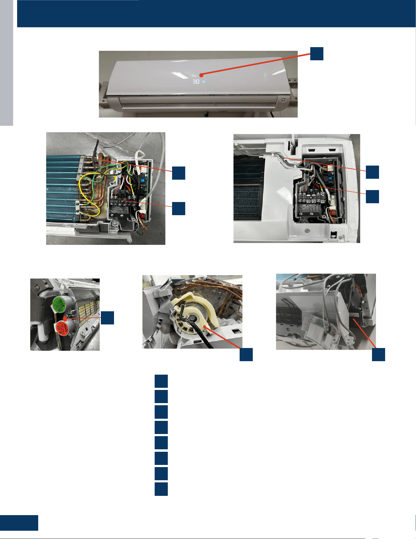
COMPONENTS
HIGHWALL
C4
ENGLISH
INDOOR UNITS
ENGLISH
,QGRRU&RPSRQHQW,GHQWLƭFDWLRQ
COMPONENTS
1
2
3
4
5
6
7
6
2
5
4
3
7
1
8
Ambient Temperature Sensor
Display Panel
Fan Motor
Louver Motors
Power Control Board(PCB)
Piping Temperature Sensor
Terminal Block
8
R454B Leakage sensor
QS24WP2BEA
INDOOR UNITS
ENGLISH
,QGRRU&RPSRQHQW,GHQWLƭFDWLRQ
COMPONENTS
1
2
3
4
5
6
7
6
2
5
4
3
7
1
8
Ambient Temperature Sensor
Display Panel
Fan Motor
Louver Motors
Power Control Board(PCB)
Piping Temperature Sensor
Terminal Block
8
R454B Leakage sensor
QS24WP2BEA
INDOOR UNITS
ENGLISH
,QGRRU&RPSRQHQW,GHQWLƭFDWLRQ
COMPONENTS
1
2
3
4
5
6
7
6
2
5
4
3
7
1
8
Ambient Temperature Sensor
Display Panel
Fan Motor
Louver Motors
Power Control Board(PCB)
Piping Temperature Sensor
Terminal Block
8
R454B Leakage sensor
QS24WP2BEA
INDOOR UNITS
ENGLISH
,QGRRU&RPSRQHQW,GHQWLƭFDWLRQ
COMPONENTS
1
2
3
4
5
6
7
6
2
5
4
3
7
1
8
Ambient Temperature Sensor
Display Panel
Fan Motor
Louver Motors
Power Control Board(PCB)
Piping Temperature Sensor
Terminal Block
8
R454B Leakage sensor
QS24WP2BEA
INDOOR UNITS
ENGLISH
,QGRRU&RPSRQHQW,GHQWLƭFDWLRQ
COMPONENTS
1
2
3
4
5
6
7
6
2
5
4
3
7
1
8
Ambient Temperature Sensor
Display Panel
Fan Motor
Louver Motors
Power Control Board(PCB)
Piping Temperature Sensor
Terminal Block
8
R454B Leakage sensor
QS24WP2BEA
GS24WP2BEA
INDOOR UNITS
ENGLISH
,QGRRU&RPSRQHQW,GHQWLƭFDWLRQ
COMPONENTS
1
2
3
4
5
6
7
4
3
8
Ambient Temperature Sensor
Display Panel
Fan Motor
Louver Motors
Power Control Board (PCB)
Piping Temperature Sensor
Terminal Block
R454B Leak sensor
8
5
7
1
6
2
QS18WP2BEA
2
6
7
1
5
83
4
1
4
2
5
7
3
6
8
Ambient Temperature Sensor
Display Panel
Fan Motor
Louver Motors
Power Control Board(PCB)
Piping Temperature Sensor
Terminal Block
R454B Leakage Sensor
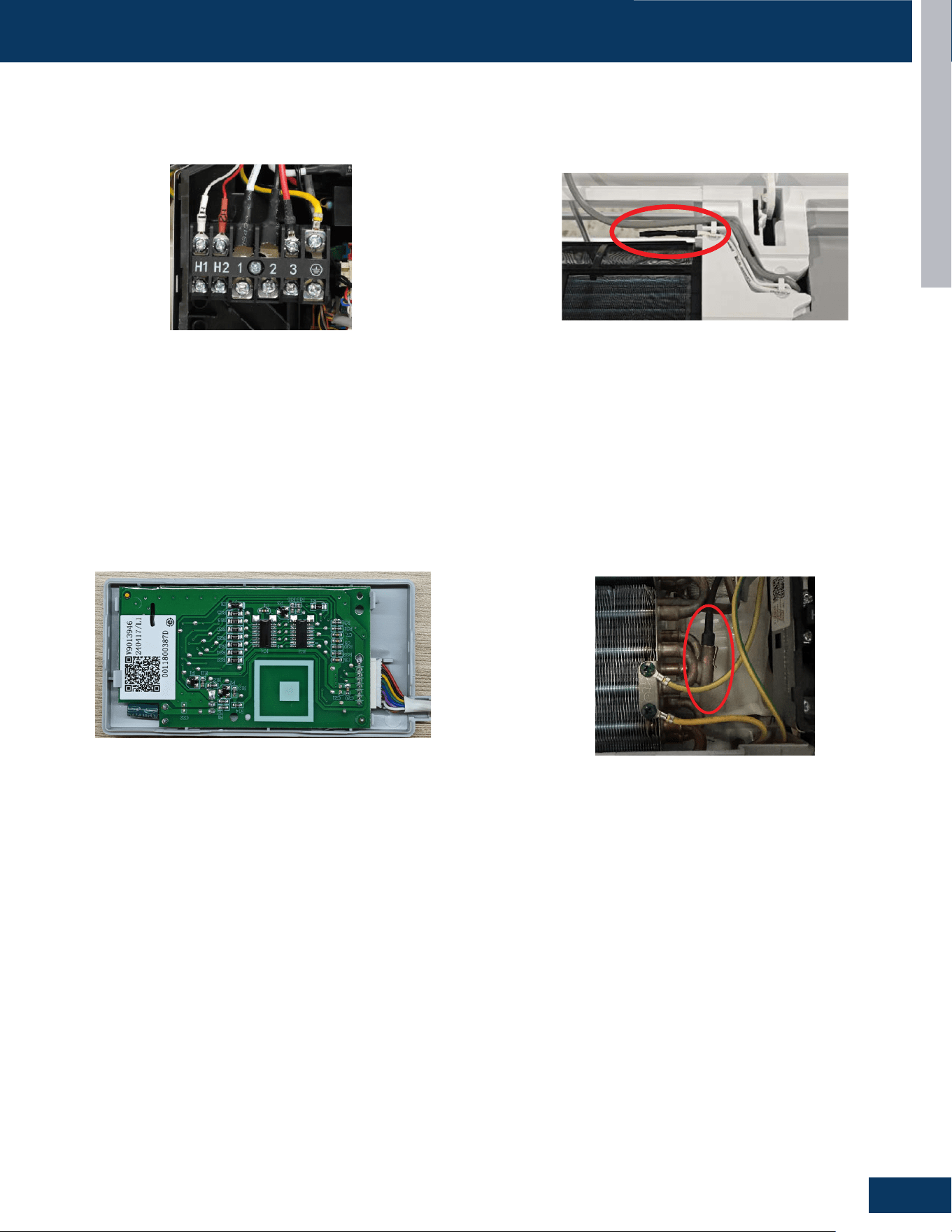
COMPONENTS
HIGHWALL
C5
ENGLISH
INDOOR UNITS
Piping Temperature
Ambient Temperature
ENGLISH
Sensor
Sensor
Display
Terminal Block
COMPONENTS
The unit terminal block receives electrical power from the outdoor
unit. There are 4 connections for electrical wires. Terminals 1 and 2 are
connected to terminals 1 and 2 of the outdoor unit. This wiring supplies
power to the indoor unit.
Terminal 3 is a communication wire. The indoor unit sends indoor air
temperature, coil temperature and temperature setpoint information to
the outdoor unit on this wire. If a splice or break in this wire is present, the
indoor unit will not be able to communicate with the outdoor unit. The
ERROR CODE will be an E7.
The Ambient (room) Temperature Sensor is a negative
coefficient thermistor that will decrease in resistance with increases in
room air temperature. The sensor is located on a clip mounted in the return
air stream.
The sensor connects to the control board at Plug CN-6.
The indoor display has an infrared communication circuit that receives
operating commands from the remote control. This display will indicate
operating modes, error codes, indoor air temperature, timer status, and
power status.
The display board connects to the control board at Plug CN-7.
The Piping Temperature Sensor is a negative coefficient thermistor that
will decrease in resistance with increases in coil temperature. The sensor is
located in a socket soldered to the surface of the indoor coil.
This sensor will monitor the temperature of the indoor coil in both
cooling and heating modes of operation. Should abnormally cold or hot
coil temperature be detected by this sensor, the system will take steps to
correct the condition or report an ERROR CODE.
The sensor connects to the control board at Plug CN-6.
QS09WP2BEA、QS12WP2BEA、QS18WP2BEA、QS24WP2BEA
Terminal Block
Display Piping Temperature Sensor
Ambient Temperature Sensor
The unit terminal block receives electrical power from the outdoor
unit. There are 4 connections for electrical wires. Terminals 1 and 2
are connected to terminals 1 and 2 of the outdoor unit. This wiring
supplies power to the indoor unit.
Terminal 3 is a communication wire. The indoor unit sends indoor air
temperature, coil temperature and temperature setpoint information
to the outdoor unit on this wire. If a splice or break in this wire is
present, the indoor unit will not be able to communicate with the
outdoor unit. The ERROR CODE will be an E7.
The indoor display has an infrared communication circuit that
receives operating commands from the remote control. This display
will indicate operating modes, error codes, indoor air temperature,
timer status, and power status.
The display board connects to the control board at Plug CN-7.
ThePipingTemperatureSensorisanegativecoecientthermistor
that will decrease in resistance with increases in coil temperature.
The sensor is
Located in a socket soldered to the surface of the indoor coil. This
sensor will monitor the temperature of the indoor coil in both cooling
and heating modes of operation. Should abnormally cold or hot coil
temperature be detected by this sensor, the system will take steps to
correct the condition or report an ERROR CODE.
The sensor connects to the control board at Plug CN-6.
The Ambient (room) Temperature Sensor is a negative
coecientthermistorthatwilldecreaseinresistancewithincreases
in room air temperature. The sensor is located on a clip mounted in
the return air stream.
The sensor connects to the control board at Plug CN-6.
GS09WP2BEA / GS12WP2BEA / GS18WP2BEA / GS24WP2BEA
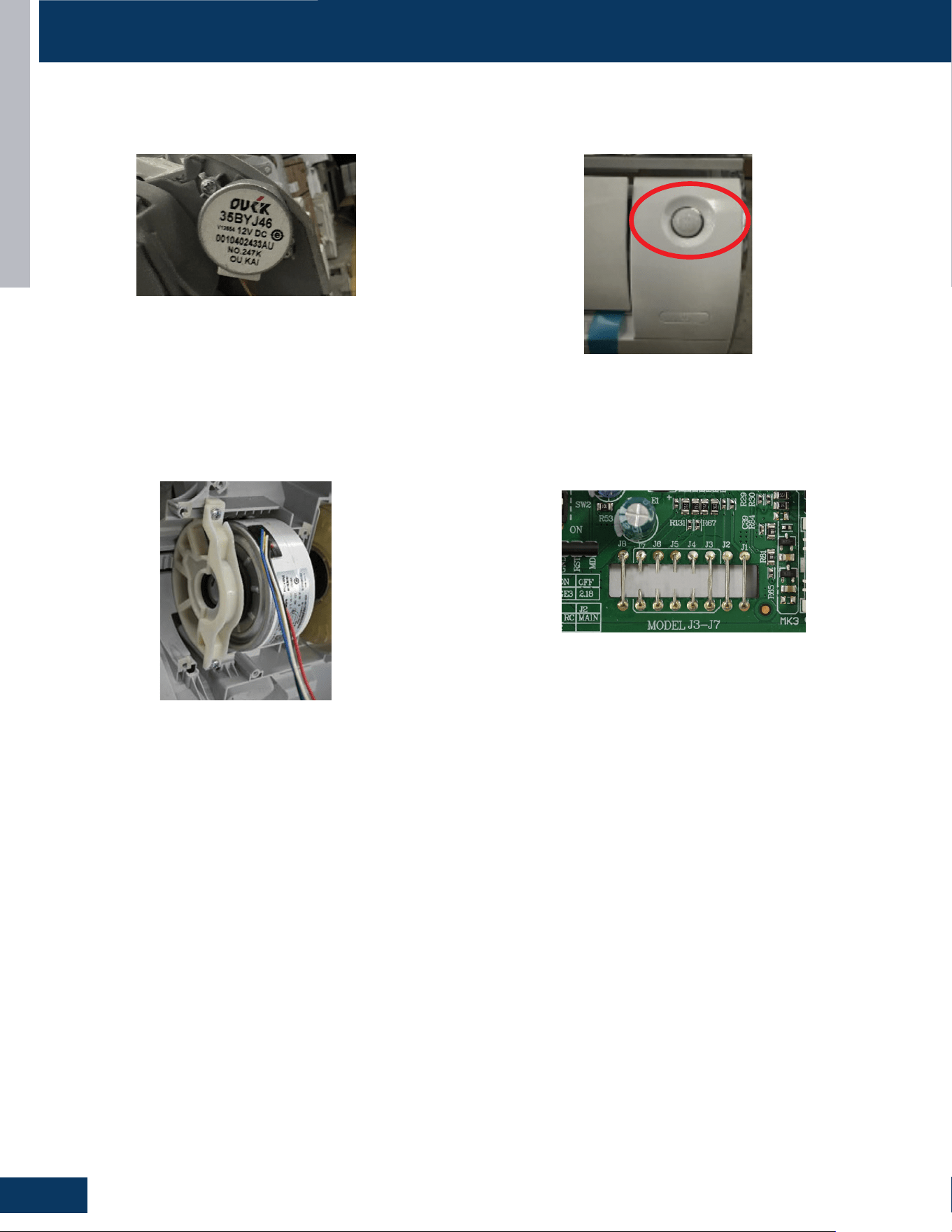
COMPONENTS
HIGHWALL
C6
ENGLISH
INDOOR UNITS
ENGLISH
Louver Stepper Motor
Fan Motor
Emergency Button
Jumper Wire Settings
The PCB has a set of jumper wires that must be checked when replacing the
PCB.
The replacement PCB is shipped with no jumper wires cut.
J7 and J3 Selects EEPROM , Cut wires to match the model type listed below:
COMPONENTS
The motor moves the louver side to side depending upon selections made
at the remote control.
These motors are connected at CN-5'
The Fan Motor is a variable speed motor. Fan speed will vary depending
upon the temperature variation from set point, or can be set with the
remote control to maintain a single set speed.
The Fan Motor is connected to the indoor control board via PLUG CN-9.
If the remote control is non-functional, the Emergency Button can be
used. 73 ℉-78℉ will bemaintained, until commands are received via
the remote control.
QS09WP2BEA、QS12WP2BEA、QS18WP2BEA
GS09WP2BEA / GS12WP2BEA / GS18WP2BEA
Louver Stepper Motor Emergency Button
Fan Motor Jumper Wire Settings
The motor moves the louver side to side depending upon selections
made at the remote control.
These motors are connected at CN-5’
If the remote control is non-functional, the Emergency Button can be
used. 73°F-78°F will be maintained, until commands are received via
the remote control.
The Fan Motor is a variable speed motor. Fan speed will vary
depending upon the temperature variation from set point, or can be
set with the remote control to maintain a single set speed.
The Fan Motor is connected to the indoor control board via PLUG
CN-9
The PCB has a set of jumper wires that must be checked when
replacing the PCB.
The replacement PCB is shipped with no jumper wires cut.
J7 and J3 Selects EEPROM , Cut wires to match the model type listed
on the unit wiring diagram (See Page C15).
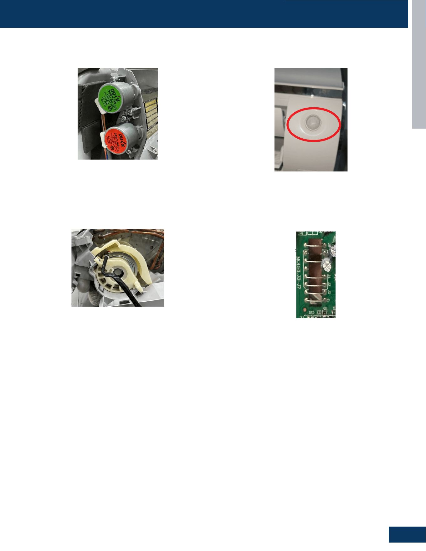
COMPONENTS
HIGHWALL
C7
ENGLISH
INDOOR UNITS
ENGLISH
Louver Stepper Motor
Fan Motor
Emergency Button
Jumper Wire Settings
The PCB has a set of jumper wires that must be checked when replacing the
PCB.
The replacement PCB is shipped with no jumper wires cut.
COMPONENTS
J7 and J3 Selects EEPROM , Cut wires to match the model type listed below:
The motor moves the louver side to side depending upon selections made
at the remote control.
These motors are connected at CN-5'
The Fan Motor is a variable speed motor. Fan speed will vary depending
upon the temperature variation from set point, or can be set with the
remote control to maintain a single set speed.
The Fan Motor is connected to the indoor control board via PLUG CN-9.
If the remote control is non-functional, the Emergency Button can be
used. 73 ℉-78℉ will bemaintained, until commands are received via
the remote control.
QS24WP2BEA
GS24WP2BEA
Louver Stepper Motor Emergency Button
Fan Motor Jumper Wire Settings
The motor moves the louver side to side depending upon selections
made at the remote control.
These motors are connected at CN-5’
If the remote control is non-functional, the Emergency Button can be
used. 73°F-78°F will be maintained, until commands are received via
the remote control.
The Fan Motor is a variable speed motor. Fan speed will vary
depending upon the temperature variation from set point, or can be
set with the remote control to maintain a single set speed.
The Fan Motor is connected to the indoor control board via PLUG
CN-9.
The PCB has a set of jumper wires that must be checked when
replacing the PCB.
The replacement PCB is shipped with no jumper wires cut.
J7 and J3 Selects EEPROM , Cut wires to match the model type listed
on the unit wiring diagram (See Page C15).
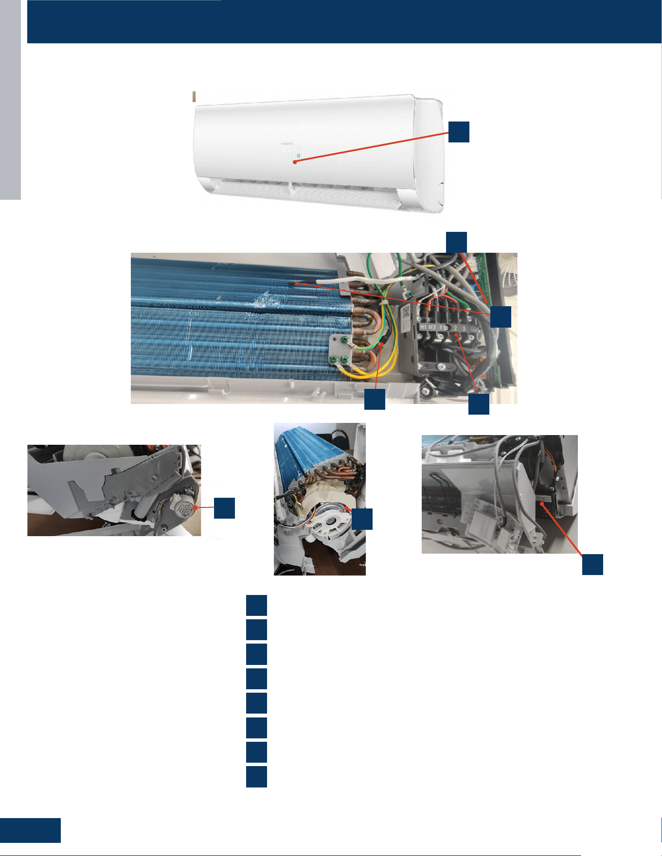
COMPONENTS
HIGHWALL
C8
ENGLISH
INDOOR UNITS
,QGRRU&RPSRQHQW,GHQWLƭFDWLRQ
ENGLISH
COMPONENTS
1
2
3
4
5
6
7
6
2
5
4
3
7
1
8
Ambient Temperature Sensor
Display Panel
Fan Motor
Louver Motors
Power Control Board(PCB)
Piping Temperature Sensor
Terminal Block
8
R454B Leakage sensor
QS07WB2BEA、QS12WB2BEA、QS15WB2BEA
INDOOR UNITS
,QGRRU&RPSRQHQW,GHQWLƭFDWLRQ
ENGLISH
COMPONENTS
1
2
3
4
5
6
7
6
2
5
4
3
7
1
8
Ambient Temperature Sensor
Display Panel
Fan Motor
Louver Motors
Power Control Board(PCB)
Piping Temperature Sensor
Terminal Block
8
R454B Leakage sensor
QS07WB2BEA、QS12WB2BEA、QS15WB2BEA
INDOOR UNITS
,QGRRU&RPSRQHQW,GHQWLƭFDWLRQ
ENGLISH
COMPONENTS
1
2
3
4
5
6
7
6
2
5
4
3
7
1
8
Ambient Temperature Sensor
Display Panel
Fan Motor
Louver Motors
Power Control Board(PCB)
Piping Temperature Sensor
Terminal Block
8
R454B Leakage sensor
QS07WB2BEA、QS12WB2BEA、QS15WB2BEA
INDOOR UNITS
,QGRRU&RPSRQHQW,GHQWLƭFDWLRQ
ENGLISH
COMPONENTS
1
2
3
4
5
6
7
6
2
5
4
3
7
1
8
Ambient Temperature Sensor
Display Panel
Fan Motor
Louver Motors
Power Control Board(PCB)
Piping Temperature Sensor
Terminal Block
8
R454B Leakage sensor
QS07WB2BEA、QS12WB2BEA、QS15WB2BEA
INDOOR UNITS
,QGRRU&RPSRQHQW,GHQWLƭFDWLRQ
ENGLISH
COMPONENTS
1
2
3
4
5
6
7
6
2
5
4
3
7
1
8
Ambient Temperature Sensor
Display Panel
Fan Motor
Louver Motors
Power Control Board(PCB)
Piping Temperature Sensor
Terminal Block
8
R454B Leakage sensor
QS07WB2BEA、QS12WB2BEA、QS15WB2BEA
GS07WB2BEA / GS12WB2BEA / GS15WB2BEA
1
2
5
1
6
7
4
3
8
4
2
5
7
3
6
8
Ambient Temperature Sensor
Display Panel
Fan Motor
Louver Motors
Power Control Board(PCB)
Piping Temperature Sensor
Terminal Block
R454B Leakage Sensor
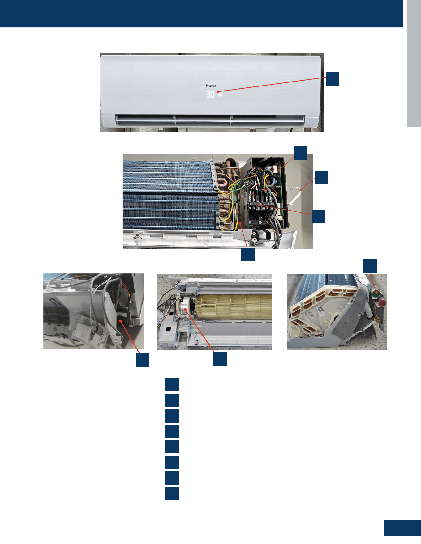
COMPONENTS
HIGHWALL
C9
ENGLISH
INDOOR UNITS
,QGRRU&RPSRQHQW,GHQWLƭFDWLRQ
ENGLISH
COMPONENTS
1
2
3
4
5
6
7
6
2
5
4
3
7
1
8
Ambient Temperature Sensor
Display Panel
Fan Motor
Louver Motors
Power Control Board(PCB)
Piping Temperature Sensor
Terminal Block
8
R454B Leakage sensor
QS18WB2BEA、QS24WB2BEA
INDOOR UNITS
,QGRRU&RPSRQHQW,GHQWLƭFDWLRQ
ENGLISH
COMPONENTS
1
2
3
4
5
6
7
6
2
5
4
3
7
1
8
Ambient Temperature Sensor
Display Panel
Fan Motor
Louver Motors
Power Control Board(PCB)
Piping Temperature Sensor
Terminal Block
8
R454B Leakage sensor
QS18WB2BEA、QS24WB2BEA
INDOOR UNITS
,QGRRU&RPSRQHQW,GHQWLƭFDWLRQ
ENGLISH
COMPONENTS
1
2
3
4
5
6
7
6
2
5
4
3
7
1
8
Ambient Temperature Sensor
Display Panel
Fan Motor
Louver Motors
Power Control Board(PCB)
Piping Temperature Sensor
Terminal Block
8
R454B Leakage sensor
QS18WB2BEA、QS24WB2BEA
GS18WB2BEA / GS24WB2BEA
2
5
1
6
7
4
3
8
1
4
2
5
7
3
6
8
Ambient Temperature Sensor
Display Panel
Fan Motor
Louver Motors
Power Control Board(PCB)
Piping Temperature Sensor
Terminal Block
R454B Leakage Sensor
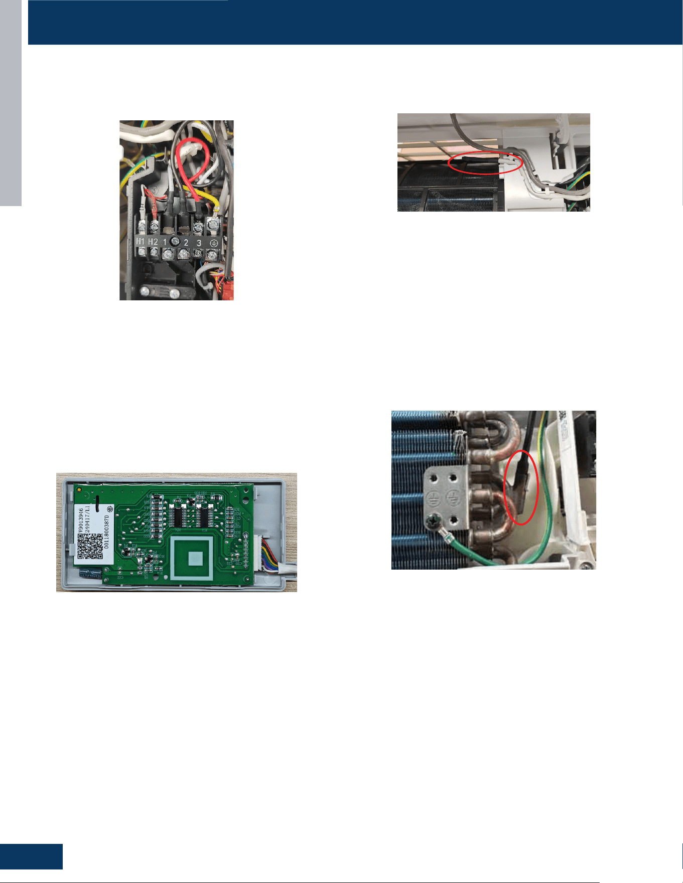
COMPONENTS
HIGHWALL
C10
ENGLISH
INDOOR UNITS
Ambient Temperature
ENGLISH
Sensor
The unit terminal block receives electrical power from the outdoor
unit. There are 4 connections for electrical wires. Terminals 1 and 2 are
connected to terminals 1 and 2 of the outdoor unit. This wiring supplies
Piping Temperature Sensor
power to the indoor unit.
The Piping Temperature Sensor is a negative coefficient thermistor that
will decrease in resistance with increases in coil temperature. The sensor is
The indoor display has an infrared communication circuit that receives
operating commands from the remote control. This display will indicate
operating modes, error codes, indoor air temperature, timer status, and
power status.
located in a socket soldered to the surface of the indoor coil.
This sensor will monitor the temperature of the indoor coil in both
cooling and heating modes of operation. Should abnormally cold or hot
coil temperature be detected by this sensor, the system will take steps to
correct the condition or report an ERROR CODE.
The sensor connects to the control board at Plug CN-6.
Display
The display board connects to the control board at Plug CN-7.
Terminal 3 is a communication wire. The indoor unit sends indoor air
temperature, coil temperature and temperature setpoint information to
the outdoor unit on this wire. If a splice or break in this wire is present, the
indoor unit will not be able to communicate with the outdoor unit. The
ERROR CODE will be an E7.
COMPONENTS
Terminal Block
The Ambient (room) Temperature Sensor is a negative
coefficient thermistor that will decrease in resistance with increases in
room air temperature. The sensor is located on a clip mounted in the return
air stream.
The sensor connects to the control board at Plug CN-6.
QS07WB2BEA、QS09WB2BEA、QS12WB2BEA、QS15WB2BEA、QS18WB2BEA、QS24WB2BEA
INDOOR UNITS
Piping Temperature
Ambient Temperature
ENGLISH
Sensor
Sensor
Display
Terminal Block
COMPONENTS
The unit terminal block receives electrical power from the outdoor
unit. There are 4 connections for electrical wires. Terminals 1 and 2 are
connected to terminals 1 and 2 of the outdoor unit. This wiring supplies
power to the indoor unit.
Terminal 3 is a communication wire. The indoor unit sends indoor air
temperature, coil temperature and temperature setpoint information to
the outdoor unit on this wire. If a splice or break in this wire is present, the
indoor unit will not be able to communicate with the outdoor unit. The
ERROR CODE will be an E7.
The Ambient (room) Temperature Sensor is a negative
coefficient thermistor that will decrease in resistance with increases in
room air temperature. The sensor is located on a clip mounted in the return
air stream.
The sensor connects to the control board at Plug CN-6.
The indoor display has an infrared communication circuit that receives
operating commands from the remote control. This display will indicate
operating modes, error codes, indoor air temperature, timer status, and
power status.
The display board connects to the control board at Plug CN-7.
The Piping Temperature Sensor is a negative coefficient thermistor that
will decrease in resistance with increases in coil temperature. The sensor is
located in a socket soldered to the surface of the indoor coil.
This sensor will monitor the temperature of the indoor coil in both
cooling and heating modes of operation. Should abnormally cold or hot
coil temperature be detected by this sensor, the system will take steps to
correct the condition or report an ERROR CODE.
The sensor connects to the control board at Plug CN-6.
QS09WP2BEA、QS12WP2BEA、QS18WP2BEA、QS24WP2BEA
Terminal Block
Display
Piping Temperature Sensor
Ambient Temperature Sensor
The unit terminal block receives electrical power from the outdoor
unit. There are 4 connections for electrical wires. Terminals 1 and 2
are connected to terminals 1 and 2 of the outdoor unit. This wiring
supplies power to the indoor unit.
Terminal 3 is a communication wire. The indoor unit sends indoor air
temperature, coil temperature and temperature setpoint information
to the outdoor unit on this wire. If a splice or break in this wire is
present, the indoor unit will not be able to communicate with the
outdoor unit. The ERROR CODE will be an E7.
The display board connects to the control board at Plug CN-7.
The indoor display has an infrared communication circuit that
receives operating commands from the remote control. This display
will indicate operating modes, error codes, indoor air temperature,
timer status, and power status.
ThePipingTemperatureSensorisanegativecoecientthermistor
that will decrease in resistance with increases in coil temperature.
The sensor is located in a socket soldered to the surface of the
indoor coil.
This sensor will monitor the temperature of the indoor coil in both
cooling and heating modes of operation. Should abnormally cold or
hot coil temperature be detected by this sensor, the system will take
steps to correct the condition or report an ERROR CODE.
The sensor connects to the control board at Plug CN-6.
The Ambient (room) Temperature Sensor is a negative
coecientthermistorthatwilldecreaseinresistancewithincreases
in room air temperature. The sensor is located on a clip mounted in
the return air stream.
The sensor connects to the control board at Plug CN-6.
GS07WB2BEA / GS09WB2BEA / GS12WB2BEA / GS15WB2BEA / GS18WB2BEA / GS24WB2BEA
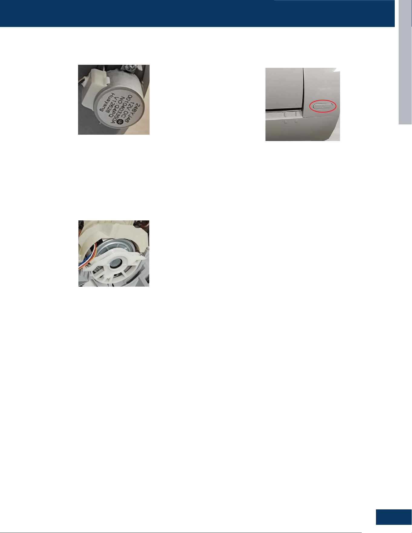
COMPONENTS
HIGHWALL
C11
ENGLISH
INDOOR UNITS
ENGLISH
Louver Stepper Motor
The Fan Motor is a variable speed motor. Fan speed will vary depending
upon the temperature variation from set point, or can be set with the
remote control to maintain a single set speed.
The Fan Motor is connected to the indoor control board via PLUG CN-9.
If the remote control is non-functional, the Emergency Button can be u
sed. 73 ℉-78℉ will be maintained, until commands are received via th
e remote control.
The motor moves the louver side to side depending upon selections made
at the remote control.
These motors are connected at CN-5'
Fan Motor
COMPONENTS
Emergency Button
QS07WB2BEA、QS09WB2BEA、QS12WB2BEA
GS07WB2BEA / GS09WB2BEA / GS12WB2BEA
Louver Stepper Motor Emergency Button
Fan Motor
The motor moves the louver side to side depending upon selections
made at the remote control.
These motors are connected at CN-5’
If the remote control is non-functional, the Emergency Button can be
used. 73°F-78°F will be maintained, until commands are received via
the remote control.
The Fan Motor is a variable speed motor. Fan speed will vary
depending upon the temperature variation from set point, or can be
set with the remote control to maintain a single set speed.
The Fan Motor is connected to the indoor control board via PLUG
CN-9.
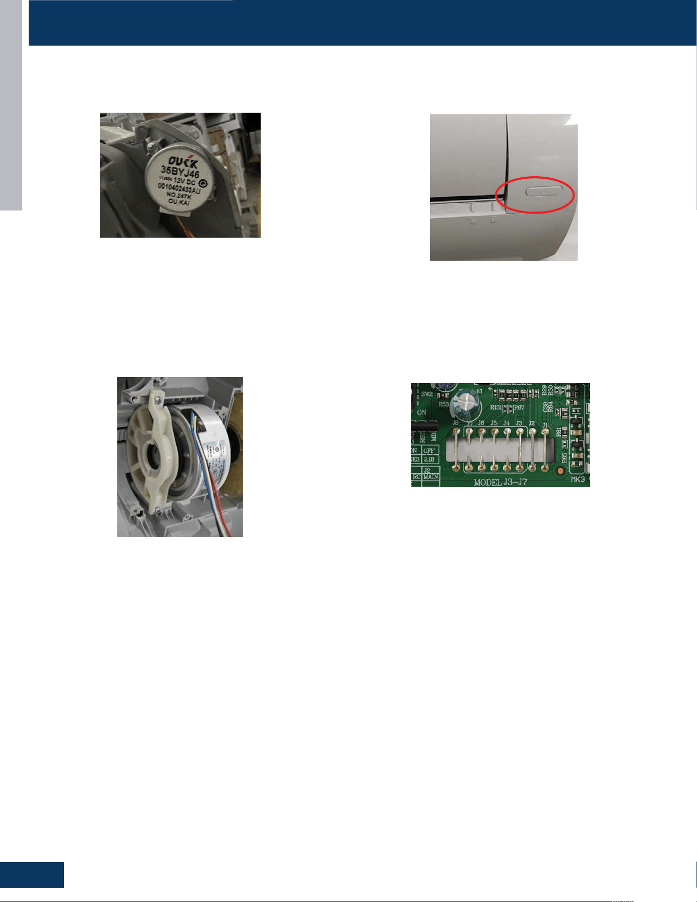
COMPONENTS
HIGHWALL
C12
ENGLISH
INDOOR UNITS
Jumper Wire Settings
The PCB has a set of jumper wires that must be checked when replacing
the PCB.
Louvera
ENGLISH
Stepper Motor
Fan Motor
Emergency Button
The replacement PCB is shipped with no jumper wires cut.
J7 and J3 Selects EEPROM , Cut wires to match the model type listed below:
COMPONENTS
If the remote control is non-functional, the Emergency Button can be
used. 73 ℉-78℉ will bemaintained, until commands are received via
the remote
The Fan Motor is a variable speed motor. Fan speed will vary depending
upon the temperature variation from set point, or can be set with the
remote control to maintain a single set speed.
The motor moves the louver side to side depending upon selections made
at the remote control.
These motors are connected at CN-5'
The Fan Motor is connected to the indoor control board via PLUG CN-9.
control.
QS15WB2BEA
GS15WB2BEA
INDOOR UNITS
ENGLISH
Louver Stepper Motor
Fan Motor
Emergency Button
Jumper Wire Settings
The PCB has a set of jumper wires that must be checked when replacing the
PCB.
The replacement PCB is shipped with no jumper wires cut.
J7 and J3 Selects EEPROM , Cut wires to match the model type listed below:
COMPONENTS
The motor moves the louver side to side depending upon selections made
at the remote control.
These motors are connected at CN-5'
The Fan Motor is a variable speed motor. Fan speed will vary depending
upon the temperature variation from set point, or can be set with the
remote control to maintain a single set speed.
The Fan Motor is connected to the indoor control board via PLUG CN-9.
If the remote control is non-functional, the Emergency Button can be
used. 73 ℉-78℉ will bemaintained, until commands are received via
the remote control.
QS09WP2BEA、QS12WP2BEA、QS18WP2BEA
Louver Stepper Motor Emergency Button
Fan Motor Jumper Wire Settings
The motor moves the louver side to side depending upon selections
made at the remote control.
These motors are connected at CN-5’
If the remote control is non-functional, the Emergency Button can be
used. 73°F-78°F will be maintained, until commands are received via
the remote control.
The Fan Motor is a variable speed motor. Fan speed will vary
depending upon the temperature variation from set point, or can be
set with the remote control to maintain a single set speed.
The Fan Motor is connected to the indoor control board via PLUG
CN-9
The PCB has a set of jumper wires that must be checked when
replacing the PCB.
The replacement PCB is shipped with no jumper wires cut.
J7 and J3 Selects EEPROM , Cut wires to match the model type listed
on the unit wiring diagram (See Page C15).
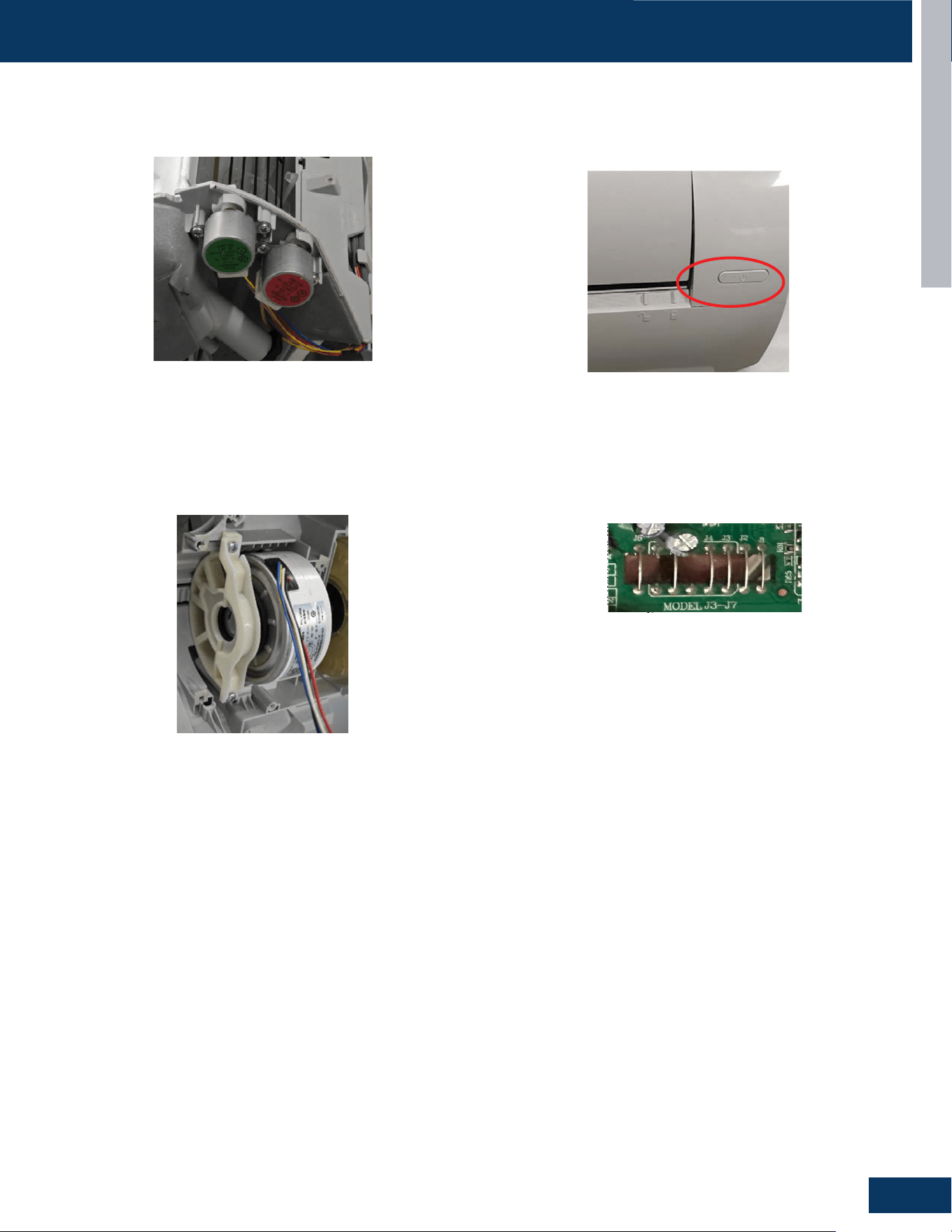
COMPONENTS
HIGHWALL
C13
ENGLISH
INDOOR UNITS
Jumper Wire Settings
The PCB has a set of jumper wires that must be checked when replacing the
PCB.
ENGLISH
Louver Stepper Motor
Fan Motor
Emergency Button
The replacement PCB is shipped with no jumper wires cut.
J7 and J3 Selects EEPROM , Cut wires to match the model type listed below:
COMPONENTS
If the remote control is non-functional, the Emergency Button can be
used. 73 ℉-78℉ will bemaintained, until commands are received via
the remote
The Fan Motor is a variable speed motor. Fan speed will vary depending
upon the temperature variation from set point, or can be set with the
remote control to maintain a single set speed.
The motor moves the louver side to side depending upon selections made
at the remote control.
These motors are connected at CN-5'
The Fan Motor is connected to the indoor control board via PLUG CN-9.
control.
QS18WB2BEA、QS24WB2BEA
INDOOR UNITS
Jumper Wire Settings
The PCB has a set of jumper wires that must be checked when replacing
the PCB.
Louvera
ENGLISH
Stepper Motor
Fan Motor
Emergency Button
The replacement PCB is shipped with no jumper wires cut.
J7 and J3 Selects EEPROM , Cut wires to match the model type listed below:
COMPONENTS
If the remote control is non-functional, the Emergency Button can be
used. 73 ℉-78℉ will bemaintained, until commands are received via
the remote
The Fan Motor is a variable speed motor. Fan speed will vary depending
upon the temperature variation from set point, or can be set with the
remote control to maintain a single set speed.
The motor moves the louver side to side depending upon selections made
at the remote control.
These motors are connected at CN-5'
The Fan Motor is connected to the indoor control board via PLUG CN-9.
control.
QS15WB2BEA
GS18WB2BEA / GS24WB2BEA
INDOOR UNITS
ENGLISH
Louver Stepper Motor
Fan Motor
Emergency Button
Jumper Wire Settings
The PCB has a set of jumper wires that must be checked when replacing the
PCB.
The replacement PCB is shipped with no jumper wires cut.
J7 and J3 Selects EEPROM , Cut wires to match the model type listed below:
COMPONENTS
The motor moves the louver side to side depending upon selections made
at the remote control.
These motors are connected at CN-5'
The Fan Motor is a variable speed motor. Fan speed will vary depending
upon the temperature variation from set point, or can be set with the
remote control to maintain a single set speed.
The Fan Motor is connected to the indoor control board via PLUG CN-9.
If the remote control is non-functional, the Emergency Button can be
used. 73 ℉-78℉ will bemaintained, until commands are received via
the remote control.
QS09WP2BEA、QS12WP2BEA、QS18WP2BEA
INDOOR UNITS
ENGLISH
Louver Stepper Motor
Fan Motor
Emergency Button
Jumper Wire Settings
The PCB has a set of jumper wires that must be checked when replacing the
PCB.
The replacement PCB is shipped with no jumper wires cut.
COMPONENTS
J7 and J3 Selects EEPROM , Cut wires to match the model type listed below:
The motor moves the louver side to side depending upon selections made
at the remote control.
These motors are connected at CN-5'
The Fan Motor is a variable speed motor. Fan speed will vary depending
upon the temperature variation from set point, or can be set with the
remote control to maintain a single set speed.
The Fan Motor is connected to the indoor control board via PLUG CN-9.
If the remote control is non-functional, the Emergency Button can be
used. 73 ℉-78℉ will bemaintained, until commands are received via
the remote control.
QS24WP2BEA
Louver Stepper Motor Emergency Button
Fan Motor Jumper Wire Settings
The motor moves the louver side to side depending upon selections
made at the remote control.
These motors are connected at CN-5’
If the remote control is non-functional, the Emergency Button can be
used. 73°F-78°F will be maintained, until commands are received via
the remote control.
The Fan Motor is a variable speed motor. Fan speed will vary
depending upon the temperature variation from set point, or can be
set with the remote control to maintain a single set speed.
The Fan Motor is connected to the indoor control board via PLUG
CN-9.
The PCB has a set of jumper wires that must be checked when
replacing the PCB.
The replacement PCB is shipped with no jumper wires cut.
J7 and J3 Selects EEPROM , Cut wires to match the model type listed
on the unit wiring diagram (See Page C15).
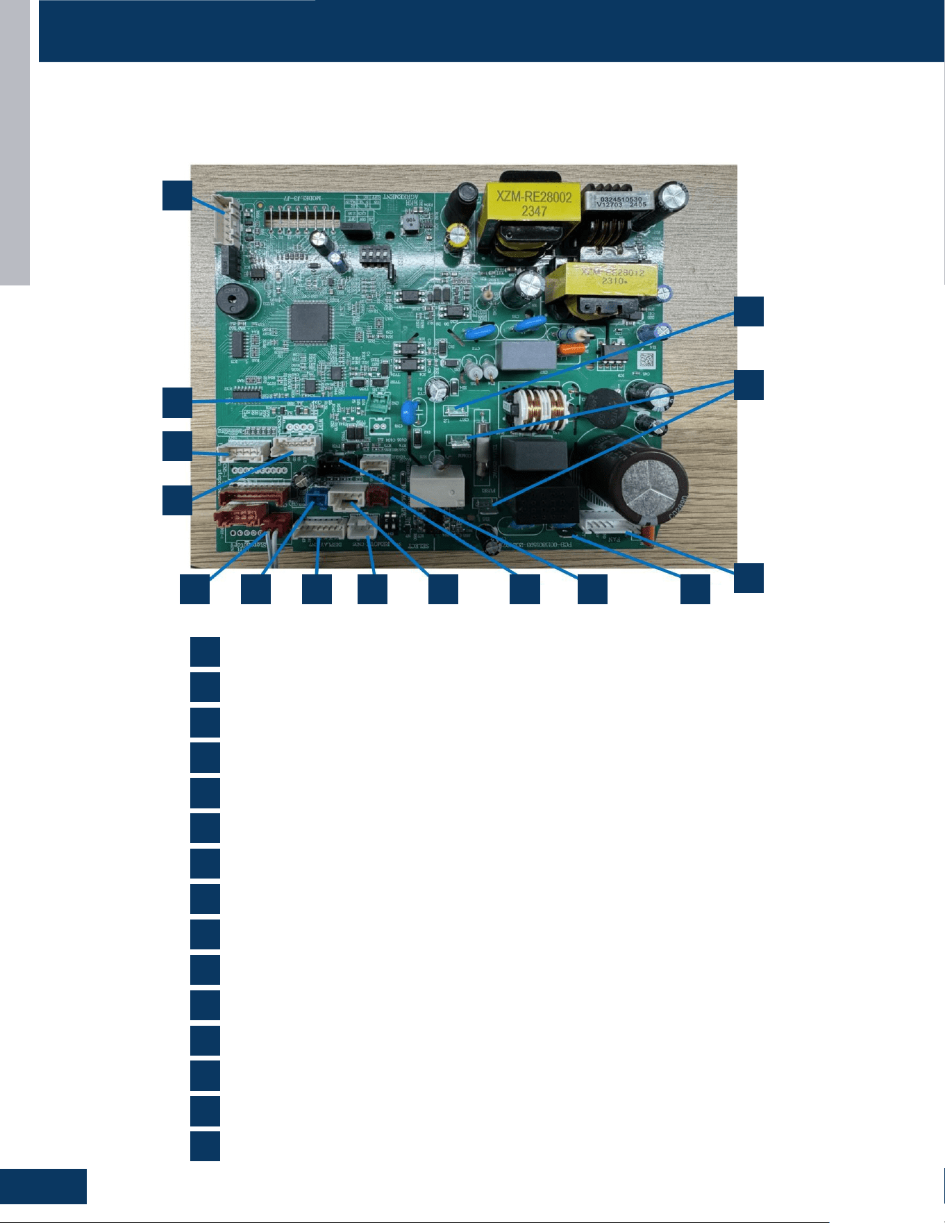
HIGHWALL
C14
ENGLISH
COMPONENTS
INTRODUCTION
PAGE 4
ENGLISH
IDU PCB
QS09WP2BEA、QS12WP2BEA、QS18WP2BEA、QS24WP2BEA
PCB Overview
GS09WP2BEA / GS12WP2BEA / GS18WP2BEA / GS24WP2BEA
GS07WB2BEA / GS09WB2BEA / GS12WB2BEA / GS15WB2BEA / GS18WB2BEA / GS24WB2BEA
15
14
13
12
5 9 7 6 10 8 11 2
4
1
1
5
9
3
7
11
14
2
6
10
13
4
8
12
15
3
CN17 and CN21: 230AC power from terminal block connections 1 (N) and 2(L)
CN27: Connector for GND
CN23: Communication connection between the indoor board and the outdoor board
CN9: Connector for the fan motor
CN14: Connector for the emergency switch
CN36: Connector for the centralized controller
CN7: Connector for the display board
CN1: Connector for non-polar wire controller
CNS51: Connector for the room cord
CN6: Connector for the temperature sensor
CN3: Connector for the leakage sensor
CN35: Connector for the WIFI
CN5: Connector for the up-down step motor
CN38: Connector for the RJ45
CN2: Connector for the OT
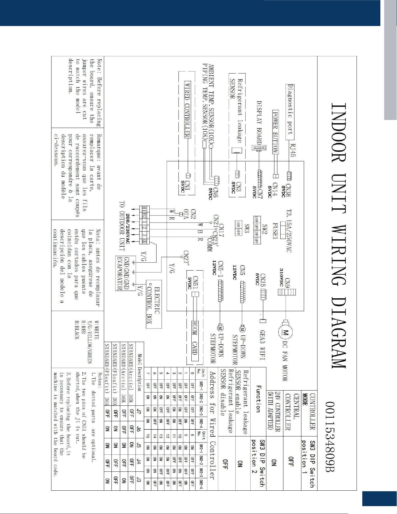
HIGHWALL
C15
ENGLISH
WIRING DIAGRAM
INTRODUCTION
PAGE 4
ENGLISH
IDU Wiring Diagram
QS09WP2BEA、QS12WP2BEA、QS18WP2BEA、QS24WP2BEA
GS09WP2BEA / GS12WP2BEA / GS18WP2BEA / GS24WP2BEA
GS07WB2BEA / GS09WB2BEA / GS12WB2BEA / GS15WB2BEA / GS18WB2BEA / GS24WB2BEA

[This page left intentionally blank]

CASSETTE
D1
ENGLISH
CASSETTE
TABLE OF CONTENTS
US09CB2BEA
US12CB2BEA
US18CB2BEA
US24LB2BEA
COMPONENTS .......................................................................................................................................................................D2
Terminal Block ........................................................................................................................................................................ D3
Blower Motor.......................................................................................................................................................................... D3
Display ................................................................................................................................................................................. D3
Blower Assembly ................................................................................................................................................................... D3
Louver Motors ........................................................................................................................................................................ D3
Piping Temperature Sensor .................................................................................................................................................. D3
Ambient Temperature Sensor .............................................................................................................................................. D3
Control Board ......................................................................................................................................................................... D4
Condensate Pump & Float Switch ........................................................................................................................................ D4
WiFi........ ................................................................................................................................................................................. D4
Refrigerant Leakage Detector .............................................................................................................................................. D4
PCB Overview ........................................................................................................................................................................ D5
WIRING DIAGRAM ................................................................................................................................................................... D6
OUTDOOR/INDOOR WIRING CONNECTIONS
........................................................................................................................D7
SERVICE PROCEDURES
..........................................................................................................................................................D8
Resistance Values .................................................................................................................................................................. D8
Fan Motor ............................................................................................................................................................................... D9
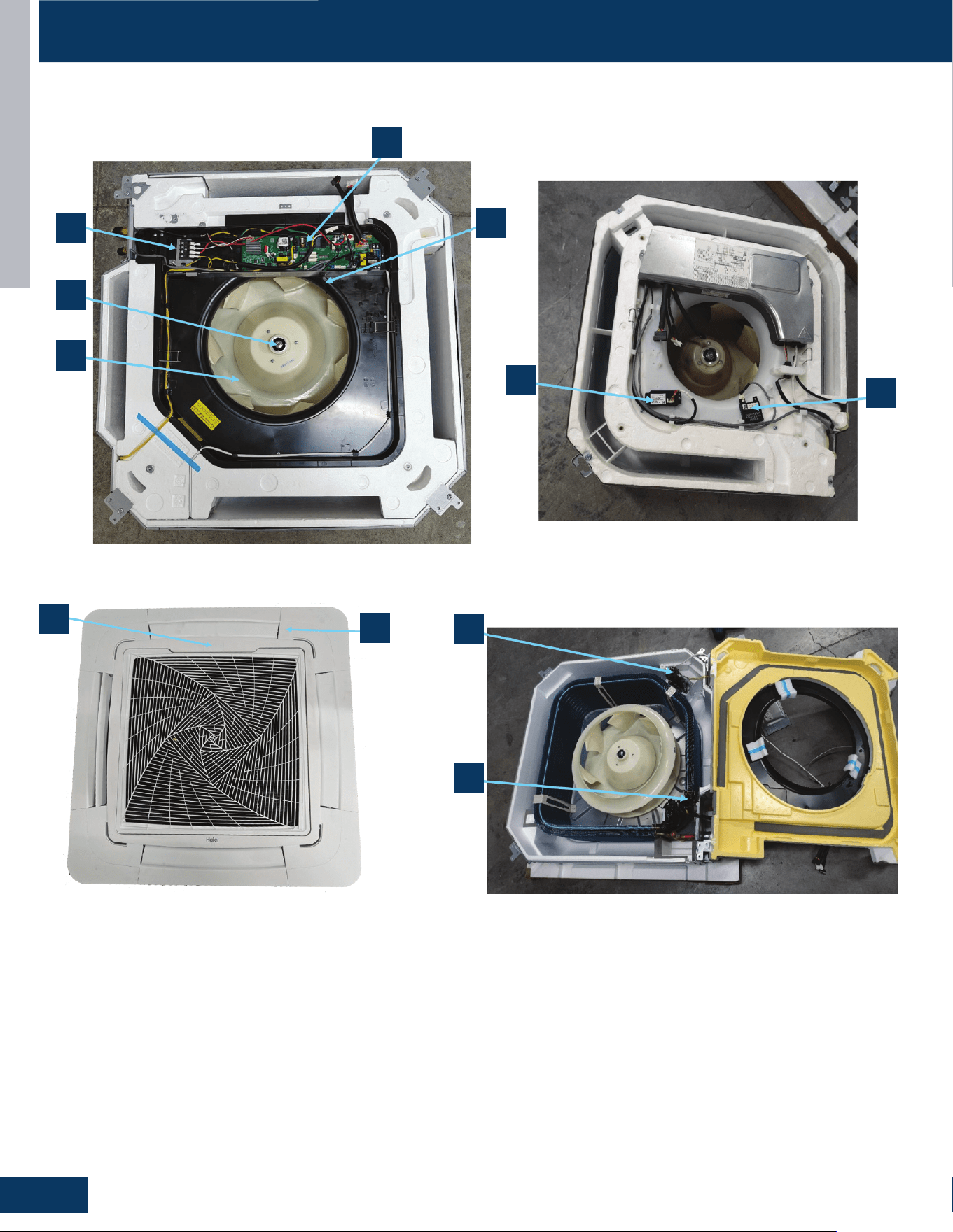
CASSETTE
D2
ENGLISH
COMPONENTS
US09CB2BEA / US12CB2BEA / US18CB2BEA / US24LB2BEA / US30LB2BEA / US36LB2BEA
1
2
4
8
7
10
3
5
11
9
6
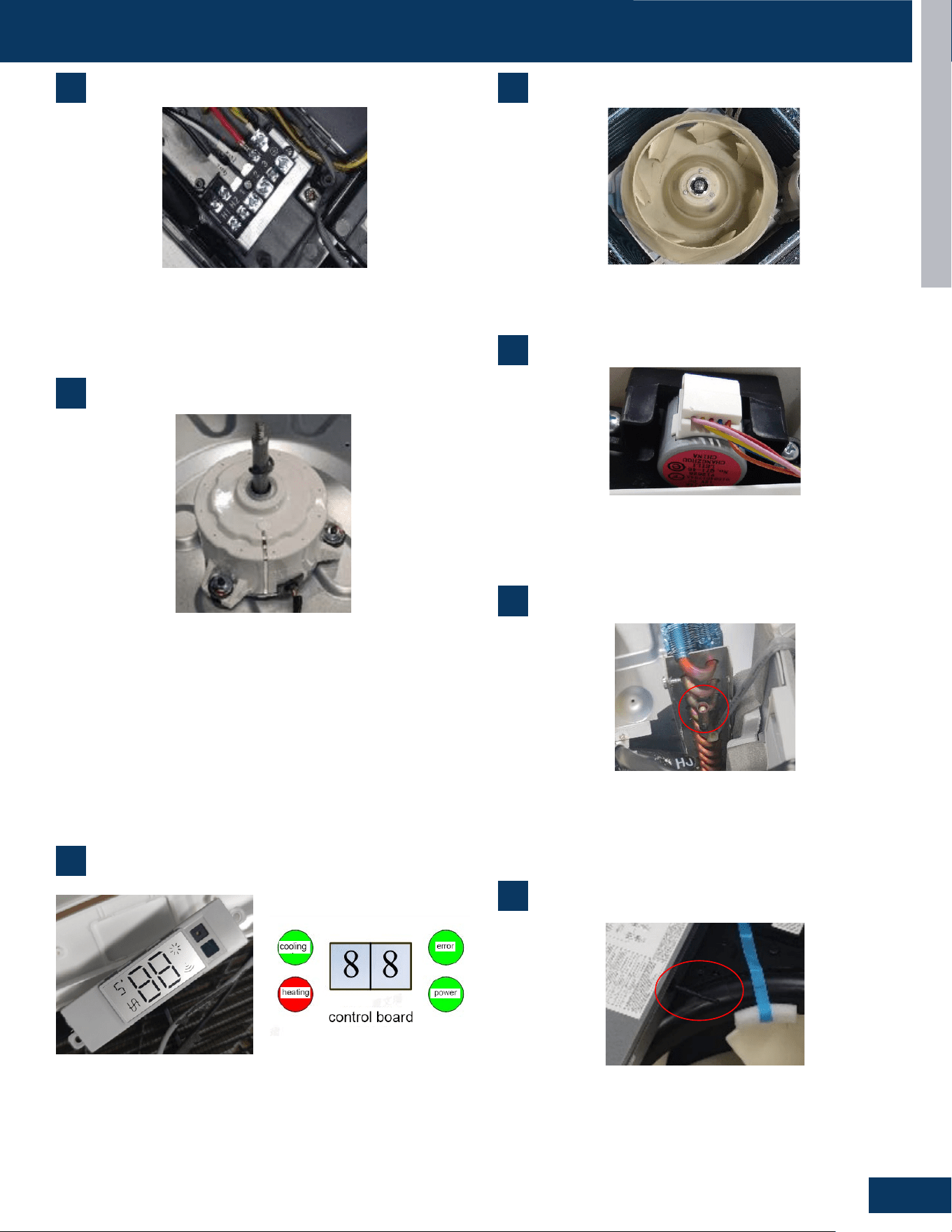
CASSETTE
D3
ENGLISH
COMPONENTS
4
5
Blower Assembly
Louver Motors
1
Terminal Block
1. Terminal Block
Power to operate the indoor unit comes from the electrical line voltage terminal block at
the outdoor unit. The wiring includes 4 wires, 1, 2, 3 and ground. Wires 1 and 3 complete
the data path. These wires should always
be
14 gauge AWG stranded cooper,
non
-
shielded
type wire. Splices in wires 1 or 3 may cause communication errors.
6
9
Power to operate the indoor unit comes from the line voltage
terminal block at the outdoor unit. The wiring includes 4 wires: 1, 2,
3 and ground. Wires 1 and 3 complete the data path. These wires
should always be 14 gauge AWG stranded cooper, non-shielded type
wire. Splices in wires 1 or 3 may cause communication errors.
The blower assembly consists of a plastic blower wheel that is
connected to a PSC indoor blower motor. A set screw holds the
blower wheel to the blower motor.
The louver motors are stepper type motors that move the louvers
up/down. The motors are controlled by pulsed voltage that cannot
be measured. If the louver does not move when it should, check for a
bind in the louvers.
2
Blower Motor
The multi-speed blower motor will change speed to match the
capacity demand from the outdoor unit. The blower motor is
controlled by both the remote control and by commands from the
outdoor unit ECU. The indoor blower motor is connected to the
indoor unit control board. The wiring from the motor to the indoor
board consists of four wire connected to pins Common, Low,
Medium, and High speeds. During normal operation, the indoor
control board will energize the indoor blower motor and request
proper speed. The motor has a run capacitor that is located in the
cassette unit’s control box. The run capacitor connects to the motor
viatwoorangewires.Thecapacitoriseld-replaceable.
2. Motor Blower
The indoor unit features a multi speed blower motor that will change speed to match
the capacity demand from the outdoor unit. Separate motors located in the indoor unit
control the operation of the motorized louvers. All of the louver motors are controlled
via commands received from the remote control. The blower motor is controlled by both
the remote control and by commands from the outdoor unit ECU.
The indoor
blower motor is a Multi Speed Fan Motor that is connected to the indoor unit control
board. The wiring from the motor to indoor board consists of 4 wires connected to pins
common, low , medium and high speeds. During normal operation, the indoor control
board will energize the indoor blower motor and request proper speed. The motor has
a run capacitor that is located in the Cassette unit
’
s control box. The run capacitor
connects to the motor via two orange wires. This capacitor is field replaceable.
The indoor unit has a display that communicates system mode. The indoor unit does not
display temperatures or diagnostic codes. When a wired controller is used, this
information is displayed on the wired controller. It is recommended to use a wired
controller with the cassette unit. When servicing a diagnostic error, ALWAYS refer to the
3. Display
outdoor unit code to make diagnostic decision
3
Display
The indoor unit has a display that communicates system mode.
The indoor unit does not display temperatures or diagnostic codes.
When a wired controller is used, this information is displayed on the
wired controller. It is recommended to use a wired controller with the
cassette unit. When servicing a diagnostic error, ALWAYS refer to the
outdoor unit code to make diagnostic decision
2. Motor Blower
The indoor unit features a multi speed blower motor that will change speed to match
the capacity demand from the outdoor unit. Separate motors located in the indoor unit
control the operation of the motorized louvers. All of the louver motors are controlled
via commands received from the remote control. The blower motor is controlled by both
the remote control and by commands from the outdoor unit ECU.
The indoor
blower motor is a Multi Speed Fan Motor that is connected to the indoor unit control
board. The wiring from the motor to indoor board consists of 4 wires connected to pins
common, low , medium and high speeds. During normal operation, the indoor control
board will energize the indoor blower motor and request proper speed. The motor has
a run capacitor that is located in the Cassette unit
’
s control box. The run capacitor
connects to the motor via two orange wires. This capacitor is field replaceable.
The indoor unit has a display that communicates system mode. The indoor unit does not
display temperatures or diagnostic codes. When a wired controller is used, this
information is displayed on the wired controller. It is recommended to use a wired
controller with the cassette unit. When servicing a diagnostic error, ALWAYS refer to the
3. Display
outdoor unit code to make diagnostic decision
4. The Blower Assembly
The blower assembly consists of a plastic blower wheel that is connected to a PSC indoor
blower motor. A set screw holds the blower wheel to the blower motor.
5. Louver Motors
The louver motors are stepper type motors that move the louvers up/down. The motors
are controlled by pulsed voltage that cannot be measured. If the louver does not move
when it should, check for a bind in the louvers.
6. Piping Temperature Sensor
The Piping Temperature Sensor senses indoor coil temperature in the cooling mode and
in the heating mode. This sensor is used for Anti Freezing and Anti Cold Blow cycles. The
sensor also provides critical temperature information to the ECU that may be used in
frequency adjustments.
7. Ambient Temperature Sensor
The Ambient Temperature Sensor senses room temperature. This sensor provides room
temperature information to the ECU for calculat
ion of inverter capacity and temperature
control. Both sensors are negative temperature coefficient type that reduce electrical
resistance as temperature rises.
8. Control Board
The indoor unit circuit board controls the switching functions of the indoor unit. All
6
Piping Temperature Sensor
The Piping Temperature Sensor senses indoor coil temperature in
the cooling mode and in the heating mode. This sensor is used for
Anti Freezing and Anti Cold Blow cycles. The sensor also provides
critical temperature information to the ECU that may be used in
frequency adjustments.
6. Piping Temperature Sensor
The Piping Temperature Sensor senses indoor coil temperature in the cooling mode and
in the heating mode. This sensor is used for Anti Freezing and Anti Cold Blow cycles. The
sensor also provides critical temperature information to the ECU that may be used in
frequency adjustments.
7. Ambient Temperature Sensor
The Ambient Temperature Sensor senses room temperature. This sensor provides room
temperature information to the ECU for calculation of inverter capacity and temperature
control. Both sensors are negative temperature coefficient type that reduce electrical
resistance as temperature rises.
8. Control Board
The indoor unit circuit board controls the switching functions of the indoor unit. All
7
Ambient Temperature Sensor
The Ambient Temperature Sensor senses room temperature.
This sensor provides room temperature information to the ECU
for calculation of inverter capacity and temperature control. Both
sensorsarenegativetemperaturecoecienttypethatreduce
electrical resistance as temperature rises.
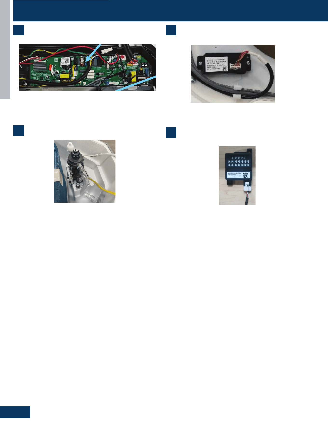
CASSETTE
D4
ENGLISH
control decisions are made by the outdoor unit ECU. The indoor board has some limited
diagnostic capability which will be covered in this manual. Condensate Pump & Float
Switch
9 Condensate Pump & Float Switch
10. Wifi
Receive and send signals, use the APP to control the air conditioning
Cooling mode (including automatic cooling operation and emergency switch setting
cooling mode) and dehumidification mode, the pump works when the compressor is on,
and the pump lags behind for 5 minutes. For other modes such as conversion heating
pump, it also continues to operate for 5 minutes according to the relevant order of the
mode.
Cooling standby, heating and fan mode, the pump does not run when the float switch is
closed. When the water tank is full, the float swit
ch is
opened,
and after the
controller detects this signal for 2 seconds, the pump starts to work. After the float
recovers, the pump continues to work with a lag of 5 minutes.
Continuous detection of water full signal for more than 5 minutes, the compressor stops
working; After the press stops, the pump continues to operate for 5 minutes. If the float
switch is still disconnected, the drainage system is reported to be faulty. After the fault,
the pump continues to operate until it is detected that the float switch is closed with a
lag of 5 minutes and the pump turns to normal operation mode.
.
8 10
9
11
Control Board WiFi
Condensate Pump & Float Switch
Refrigerant Leakage Detector
The indoor unit circuit board controls the switching functions of the
indoor unit. All control decisions are made by the outdoor unit ECU.
The indoor board has some limited diagnostic capability which will be
covered in this manual. Condensate Pump & Float Switch
Receives and sends wireless signals to enable APP control of system
operation
In cooling mode (including automatic cooling operation and
emergencyswitchsettingcoolingmodeanddehumidicationmode),
the pump operates when the compressor is on, and the pump 5
minutes after. For other modes such as conversion heating pump, it
also continues to operate for 5 minutes after.
Cooling standby, heating and fan mode, the pump does not run.
Whentheoatswitchisopened,thewatertankisfull.
After the controller detects this signal for 2 seconds, the pump starts
towork.Aftertheoatrecovers,thepumpcontinuestowork5foran
additional minutes.
Continuous detection of water full signal for more than 5 minutes, will
stop the compressor. The pump continues to operate for 5 minutes.
Iftheoatswitchisstillopenordisconnected,thedrainagesystemis
reported to be faulty. After the fault, the pump continues to operate
untilitisdetectedthattheoatswitchisclosedorfor5minutes.
Detects the concentration of refrigerant in the air. When the
refrigerant leakage sensor detects a concentration = 10% of lower
ammabilitylimit,analarmistriggered.
bA No refrigerant leakage detector is installed.
1. The sensor is not detected.
2. If the bA fault is still reported, the refrigerant sensor is abnormal.
AA LFL leakage higher than X% is detected.
1. Cutotherefrigerant,whetherAbisdisplayedafterthe
refrigerant drops. If so, the sensor is normal; If Ab is not displayed
consistently after the refrigerant concentration decreases, the
detector is abnormal and needs to be replaced.
AC Communication failure.
1. Check wiring connections. If the fault persists, replace the sensor
cable.
Ad Self-check fault.
1. The refrigerant sensor is missing (open circuit), install a new
detector.
2. Detector bypass (short circuit). Replace the detector wiring
harness. If the fault persists, replace the detector.
3. Detector output exceeds the declared range of the sensor or the
expected state is abnormal, replace the refrigerant sensor.
AE/AF Detector life warning
1. The fault is cleared after a new sensor is installed. If the fault
persists, it may be a drive board fault.
Dip Switch SW1-5:
0: Refrigerant leakage detector function valid
1: Refrigerant leakage detector function invalid
COMPONENTS
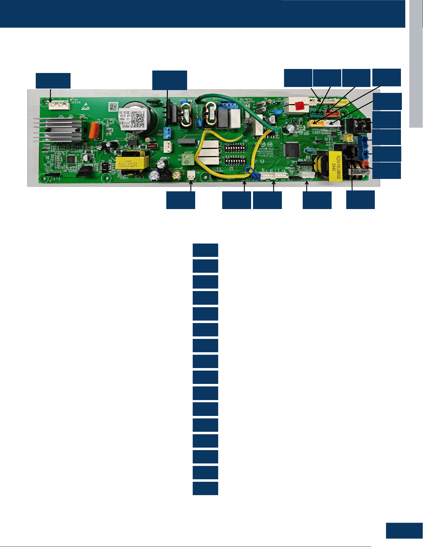
CASSETTE
D5
ENGLISH
0151800985
US09CB2BEA US12CB2BEA US18CB2BEA US24LB2BEA US30LB2BEA US36LB2BEA
CN2
CN3
CN5
CN7
CN8
CN10
CN11
CN17
CN211
CN11
CN10
CN23
CN3
CN8
CN19
CN7
CN22
CN18
CN21
CN17
CN20
CN2
CN5
CN24
CN18
CN19
CN20
CN21
CN22
CN23
CN24
CN211
COMPONENTS
PCB Overview
RJ45 Communication
Remote Control
WiFi
Sensor
Float Switch
Wired Controller
Light Board
Swing Motor
Swing Motor
AC Drain Pump
Swing Motor
Swing Motor
OTA485 Communication
Refrigerant Sensor
DC Drain Pump
Fan Motor
0151800985
CN211
CN19
CN11
CN18
CN21
CN17
CN17
CN10
CN23
CN3
CN8
CN2
CN7CN5CN22CN24
CN2
CN3
CN5
CN10
CN18
CN21
CN7
CN11
CN19
CN22
CN24
CN8
CN17
CN20
CN23
CN211
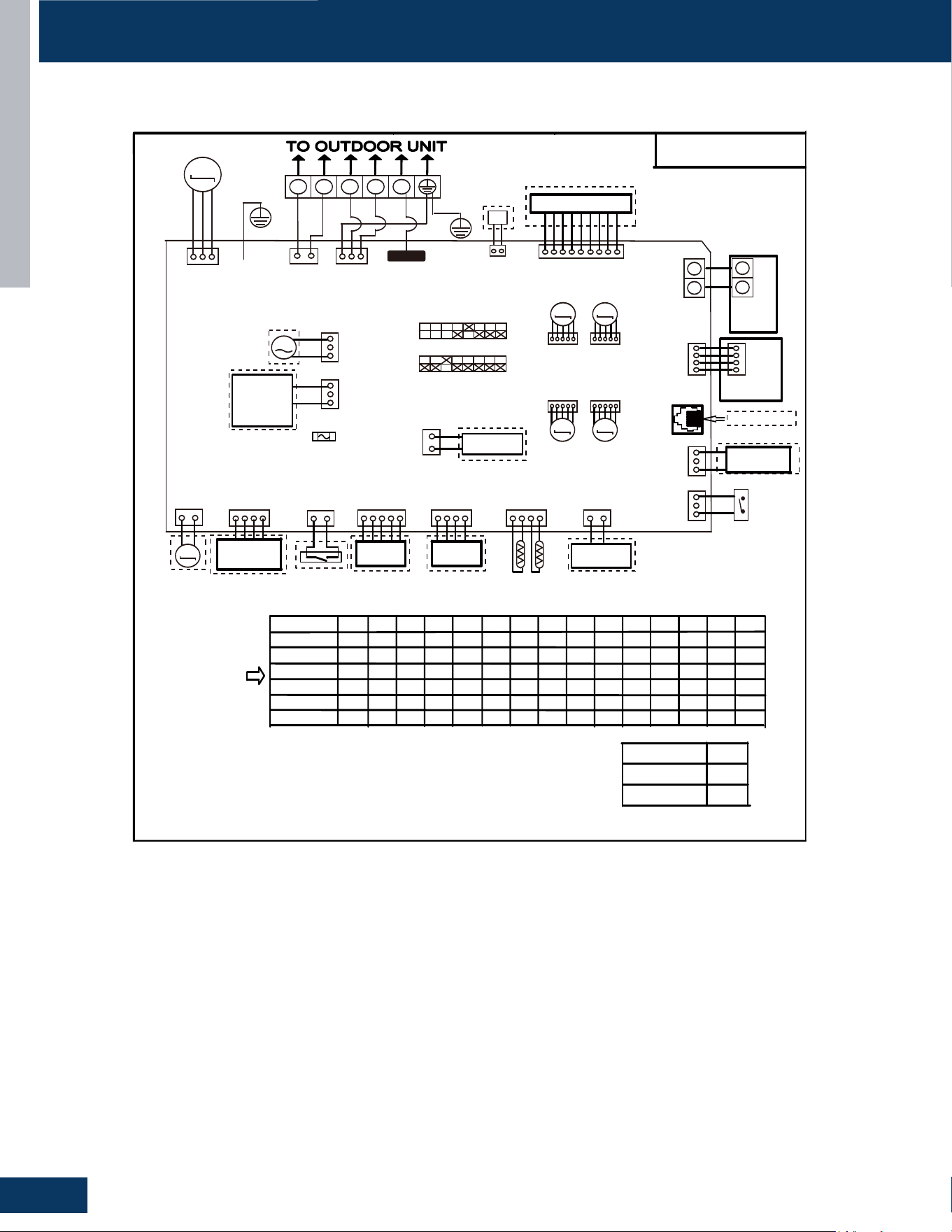
CASSETTE
D6
ENGLISH
WIRING DIAGRAM
US09CB2BEA / US12CB2BEA / US18CB2BEA / US24LB2BEA / US30LB2BEA US36LB2BEA
F a c t o r y de f au l t s e t t i ng
o f t he D I P s w i t c h e s
S W 1 - 1 S W 1 - 2 S W 1 - 3 S W 1 - 4 S W 1 - 6 S W 1 - 7 S W 1 - 8 S W 3 - 1 S W 3 - 2 S W 3 - 3 S W 3 - 4 S W 3 - 5 S W 3 - 6 S W 3 - 7 S W 3 - 8
US09CB2BEA
M O D E L
OFF O FF OFF O F F O F F O F F O F F O F F O F F O F F O F F O F F O F F
ON
O F F OFF O F F O F F O F F O F F O F F O F F O F F O F F O F F O F F
O F F O F F O F F O F F O F F O F F O F F O F F O F F O F F
O N
O FF
ON O N
O F F O F F O F F O F F O F F O F F O F F O F F O F F O F F
US12CB2BEA
US18CB2BEA
US24LB2BEA
US30LB2BEA
ON
OFF
OFF
O F F O F F O F F F O F F
O F
O F F O F F O F F O F F
O F F
O FF
ON
O FF
N O T E :
1 . D a s h e d
p a r t s a r e op t
i on a l .
2 . P l e a s e r e f e r t o s e r v i c e m a n ua l t o g e t d e t a i l s o f t h e D I P s w i t c he s d e f i n i t i o n .
3 . D o n o t c h ang e t h e D I P s w i t c h e s s e t t i ng w i t h o u t t e c hn i c a l s u p p o r t .
4 .G e t d e t a i l s f r o m t r ou b l e s h o o t i n g l i s t ab o u t L E D i nd i c a t i o n.
5 . A b b r e v i a t i o n
:
R D - r e d, W - w i t h e , B L K - b l a c k, B L U - b l u e , G R N - g r e e n , Y L - y e l l o w , Y / G - y e l l o w / g r ee n , E . A . O :
e x t e r n a l a l a r m o u t p u t, T r
:
i n d o o r u n i t a m b i e n t ( r oo m ) t e m p e r a t u r e s e n s o r , T p
:
i n d o o r u n i t p i p e ( c o i l )
t e m p e r a t u r e s en s o r .
6 . T he po r t C N 4 & C N 1 0 a r e d r y c o n t a c t o u t p u t po r t f o r p a r t i c u l a r u s e , do n o t c o n n e c t o t h e r d e v i ce w i t h ou t
t e c h n i c a l pe r s on s uppo r t .
US36LB2BEA
OFF OFF OFF OFF OFF OFF OFF OFF OFF OFF OFF ON ON
UVC
1 2 3
H1 H2
M
Display PCB
M
M
M M
X Y
WIRED
CONTROLLER
Y X
CN23
BLU
Air conditioning
refrigerant detector
DC Water Pump
GEA
WIFI MODULE
WIFI MODULE
Tp
Tr
DC FAN
FLOAT SWITCH
CN8
Central Controller
CN3
CN7 CN4
CN5 CN9 CN3
CN2
BLK
TO RJ45 device
Humidity Sensor
CN1 CN24
M
Room Card
M
FRELAY FOR
FRESH AIR
MOTOR(dry
Contact,rating
-230VAC,3A)/
E.A.0
AC Water Pump
FRELAY FOR
Electric Heater
CN17 CN20
YL
CN18 CN21
WH
GR RD
WH
CN19
BLU
CN15
WH
CN13
GR
CN211
WH
CN16
BLU
CN6
CN14
WH
CN11
WH
ON SW1
ON SW3
BLU
WH WH
YL
CN22
GRN
WH
BLK
RD BLU
CN10
G/Y
RD
BLK
WH
YL
YL
SWING1
M
SWING1 SWING2
SWING3 SWING4
BRN
RD
OFF
OFF ON
OFF ON
OFF ON
OFF ON
OFF ON
G/Y
Emergency
Stop
FUSE1
T6.3A 250VAC
(T8.0A 250VAC)
Possible reasons
I n do o r un i t t r ou b l e s h o o t i n g
0150577394
Wired
controller
display
07 flashing
on the upper
right corner
Outdoor error
code +20 cor-
respond HEX
code
Note:
1.To get much more details about the out door unit failure,please refer tothe outdoor unit trouble
shooting list.
2.SW1-5OFF Start the refrigerant sensor function,SW1-5ON Disable the refrigerant sensor function.
Panel
display
bA
The refrigerant det-
ector is not installed
bA
No refrigerant detector is installed
AA
AA
Refrigerant leakage
Fault “AA” cannot be cleared. Only the
leakage concentration decreases and
the fault is turned to “Ab”.See the te-
chnical manual for elimination
Ac
Ac
The communication
of the refrigerant se-
nsor is faulty
When the air conditioner is running, t-
he cable harness of the refrigerant se-
nsor falls off.
Ad
Ad
The refrigerant sens-
or self-check is faulty
The refrigerant sensor is faulty.
AE
AE
Refrigerant sensor
life threshold
Refrigerant sensor life threshold rem-
inder
AF
AF
The refrigerant sens-
or expires
Refrigerant sensor life threshold, ne-
ed to be replaced
E1
E2
E4
F1-F45
01
02
04
07
0C
E7
E8
E12
E13
E14
0D
0E
Contents of Malfun-
ction
Malfunction of indoor
unit ambient tempera-
ture sensor
Malfunction of indoor-
unit piping temperatur-
e sensor
EEPROM wrong ofin-
door PCB
Abnormal communic-
ation between indoor
and outdoor units
Abnormal communic-
ation between wiredc-
ontroller and indoor
unit
Malfunction of drain-
system
Zero cross sigal wr-
ong
Indoor unit DC fanm-
otor abnormal
Outdoor unit error
Sensor disconected,or broken,or at
wrong position,orshort circuitsor.
Sensor disconected,or braken,or at
wrong position,orshort circuit.
EEPROM chip disconectedor broken
or wrong programmed,or PCB broken.
Wrong connection,or thewires be dis-
conected or wrong adress setting of
indoorunit or faulty power supplyor fa-
ulty PCB
Wrong connection or wiredcontroller
broken,or PCB faulty.
Pump motor disconnectedor at wrong
position,or thefloat switch,disconnec-
ted,or at wrong position, or theshort
circuit bridge disconneted
Zero cross sigal detected wrong.
DC Fan motor disconnectedor DC
Fan broken or circuitbroken
See correspond Outdoorunit error tro-
uble shooting.Remark: F1 means ou-
tdoor error code 1, F2 meansoutdoor
error code 2, andso on.
Led2 flash times
tens
place
ones
place
0
1
0
0
0
0
0
0
0
2
4
7
8
12
13
14
M(≥2)
N(≥0)
18
6
17
0
17
2
17
3
17
4
17
5
SW1-5
Refrigerant Sensors
have
no
OFF
ON
G/Y
CON1
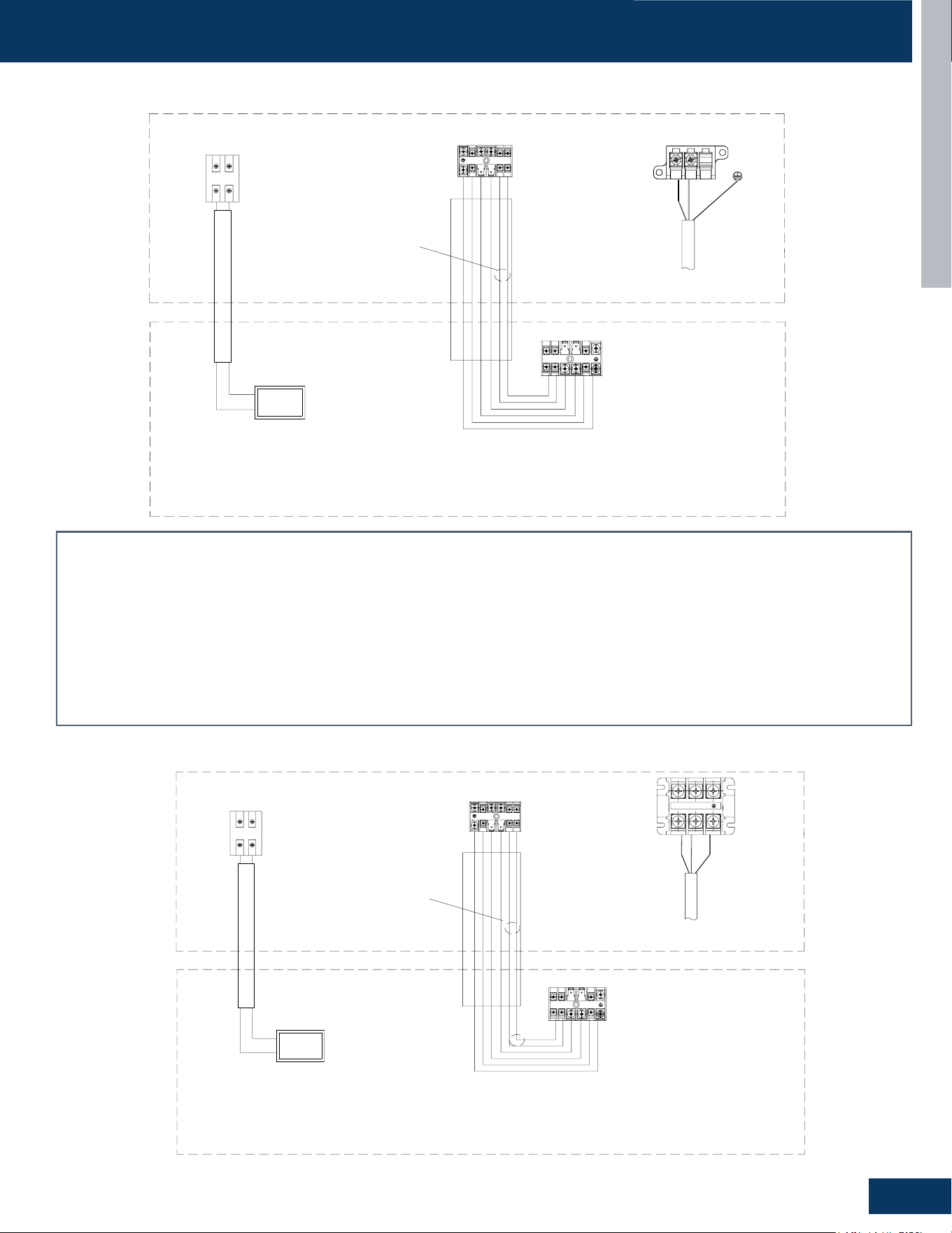
CASSETTE
D7
ENGLISH
OUTDOOR/INDOOR WIRING CONNECTIONS
US24LB2BEA
Indoor Unit B
C1 C2
OTA
the Indoor Unit
Central Controller
@2
@4
A
B
@3
These communication cable
should be shielded twisted
pair type.
Central
Controller
Outdoor Unit
Power supply cable, 3*4mm²
Communication cable for indoor unit and outdoor unit,4*2.5mm²
Caution
:
①
The OTA communication cable should be shielded twisted pair type,
and need to make the cable's shielded layer connect to earth or the unit
shell which connect to earth (indoor side or outdoor side).
②
There should be independent pipeline for communication wire.
③
The distance between OTA communication cable and the power supply
cable should be at least 10cm.
④
Ensure specifically that there is an earth leakage breaker (ELB)
installed for both the outdoor and indoor unit.
⑤
If the installation is already fitted with an earth leakage breaker (ELB),
ensure that its rated current is large enough to withstand the current of the
units (both outdoor and indoor).
@3:
@1:
@2:
Communication cable for central controller, wire specification to
refer to wired controller manual and real installation length.
@4:
The OTA communication cable (H1/H2) should be 2 x 16 AWG shielded.
Indoor Unit
Power Supply
1Ph,208/230V,60Hz
Power
@1
L1
L2
H1
H2 1
2
3
H1
H2 1
2
3
Caution:
1. The OTA communication cable should be shielded twisted pair type, and need to make the cable’s shielded layer connect to earth or the unit shell which
connect to earth (indoor side or outdoor side).
2. There should be independent pipeline for communication wire.
3. The distance between OTA communication cable and the power supply cable should be at least 10cm.
4. Ensurespecicallythatthereisanearthleakagebreaker(ELB)installedforboththeoutdoorandindoorunit.
5. Iftheinstallationisalreadyttedwithanearthleakagebreaker(ELB),ensurethatitsratedcurrentislargeenoughtowithstandthecurrentoftheunits(both
outdoor and indoor).
@1 Power supply cable, 3*4mm²
@2 Communication cable for indoor unit and outdoor unit,4*2.5mm²
@3Communicationcableforcentralcontroller,wirespecicationtorefertowiredcontrollermanualandrealinstallationlength.
@4 The OTA communication cable (H1/H2) should be 2 x 16 AWG shielded.
Indoor Unit B
C1 C2
OTA
the Indoor Unit
Central Controller
@2
@4
A
B
@3
These communication cable
should be shielded twisted
pair type.
Central
Controller
Outdoor Unit
Power supply cable, 3*4mm²
Communication cable for indoor unit and outdoor unit,4*2.5mm²
Caution
:
①
The OTA communication cable should be shielded twisted pair type,
and need to make the cable's shielded layer connect to earth or the unit
shell which connect to earth (indoor side or outdoor side).
②
There should be independent pipeline for communication wire.
③
The distance between OTA communication cable and the power supply
cable should be at least 10cm.
④
Ensure specifically that there is an earth leakage breaker (ELB)
installed for both the outdoor and indoor unit.
⑤
If the installation is already fitted with an earth leakage breaker (ELB),
ensure that its rated current is large enough to withstand the current of the
units (both outdoor and indoor).
@3:
@1:
@2:
Communication cable for central controller, wire specification to
refer to wired controller manual and real installation length.
@4:
The OTA communication cable (H1/H2) should be 2 x 16 AWG shielded.
Indoor Unit
Power Supply
1Ph,208/230V,60Hz
Power
@1
H1
H2 1
2
3
L1
L2
H1
H2 1
2
3
US30LB2BEA / US36LB2BEA
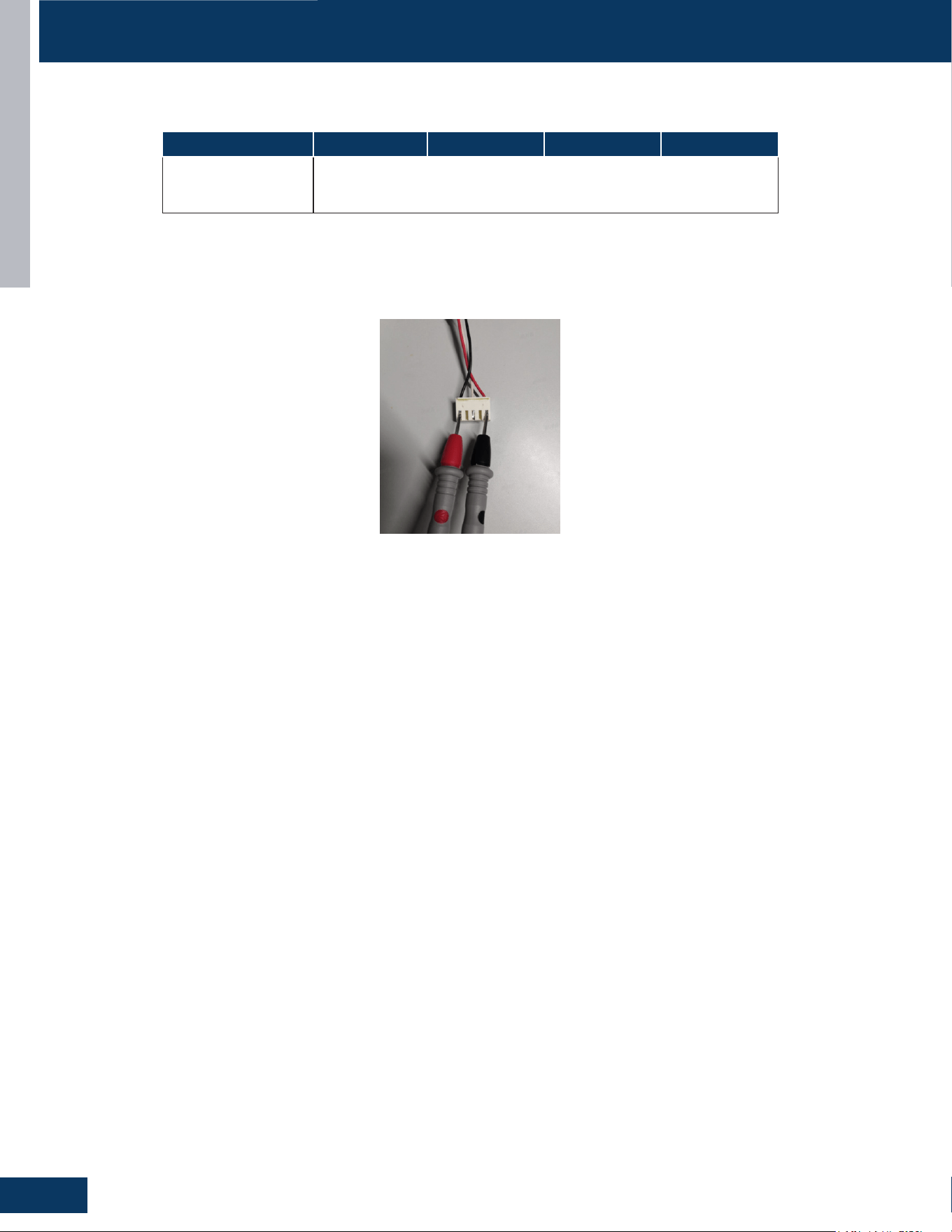
CASSETTE
D8
ENGLISH
SERVICE PROCEDURES
Resistance Values
Measure the Resistance :
Use a multimeter to measure the resistance between any two phases (U, V, W) of the motor (as shown in the following diagram).
Model US09CB2BEA US12CB2BEA US18CB2BEA US24LB2BEA
Louver Resistance
Value
0150401794A,300Ω±7%
0150401794B,300Ω±7%
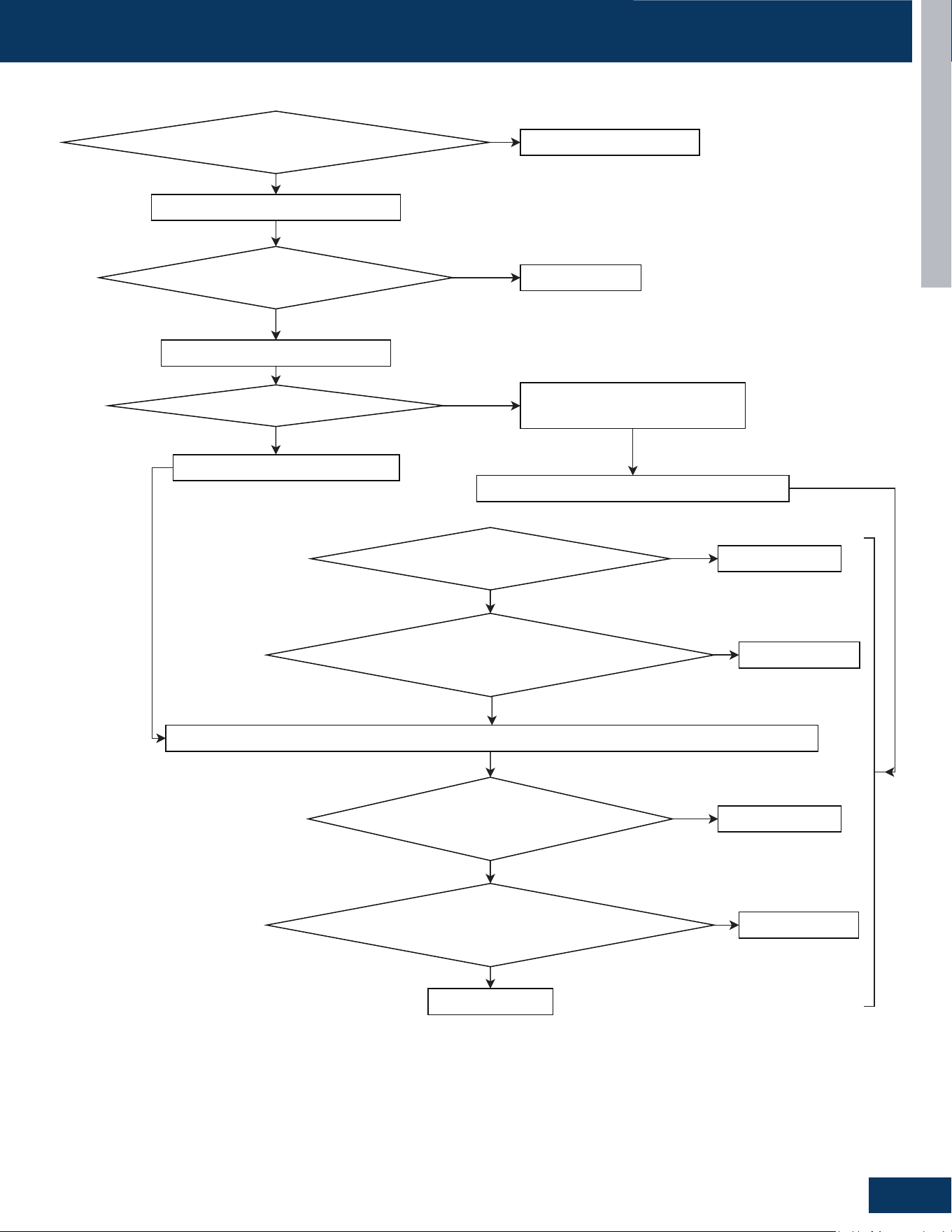
CASSETTE
D9
ENGLISH
SERVICE PROCEDURES
SYJS-05-2024 REV.A
Troubleshooting for indoor Unit
3. Indoor DC Fan Motor or Relevant Drive Circuit Abnormality
Error
Code
Controller
0E Indoor DC Fan Motor or Relevant Drive Circuit Abnormality
Method of Error Detection
The speed feedback signal FG detected by the Hall IC during fan motor operation
is used to determine whether the fan motor status is normal.
Error Decision Conditions
The real speed calculated from feedback signal FG(feedback pulse, Hall IC
detect) do not meet the tolerance range of the fan motor speed command.
Supposed Causes
•
Operation halt due to short circuit inside the fan motor winding
•
Operation halt due to breaking of wire inside the fan motor
•
Operation halt due to breaking of the fan motor lead wires
•
Operation halt due to faulty capacitor of the fan motor
•
Detection error due to faulty indoor unit PCB
Troubleshooting
be damaged.
Is the IDU AC power supply
voltage normal (196-253VAC)?
Turn off the power and rotate fan by hand
Does fan rotate smoothly and
without obvious friction?
Power on and set the unit as fan mode
Does the fan motor rotate?
N
N
Y
Y
N
Turn off the power and disconnect fan
motor connector, then power on.
Correct the IDU power supply
Replace fan motor
Turn off the IDU to stop the fan motor
Check process for IDU PCB fan motor output port
*Is the motor DC power supply voltage
between 290 ~ 350V DC?
Replace fan motor
*Is the motor control power voltage
DC 15V output voltage
between 13.5~16.5VDC?
Replace IDU PCB
Turn off the power and disconnect fan motor connector, then power on again. Set the unit as fan mode
*Is the motor speed
command voltage output voltage Vsp
between
1.5~6VDC?
Replace fan motor
*Is the motor Speed
feedback pulse signal FG Voltage output voltage
between
2~9VDC?
Replace fan motor
Replace IDU PCB
N
Y
N
Y
Y
N
Y
N
Fan Motor

[This page left intentionally blank]

CONSOLE
E1
ENGLISH
CONSOLE
US09FB2BEA
US12FB2BEA
US18FB2BEA
TABLE OF CONTENTS
COMPONENTS ....................................................................................................................................................................... E2
Louver Motor .......................................................................................................................................................................... E2
Flap....... ...................................................................................................................................................................................E2
Step Motor ..............................................................................................................................................................................E2
Electrical Box ...........................................................................................................................................................................E3
Pipe Bushing ............................................................................................................................................................................E3
Joint Connector ...................................................................................................................................................................... E3
Flap....... ...................................................................................................................................................................................E3
Fan Guard ................................................................................................................................................................................E3
Fan Wheel ................................................................................................................................................................................ E3
Fan Motor ................................................................................................................................................................................E3
PCB Overview .........................................................................................................................................................................E4
WIRING DIAGRAM ................................................................................................................................................................... E5
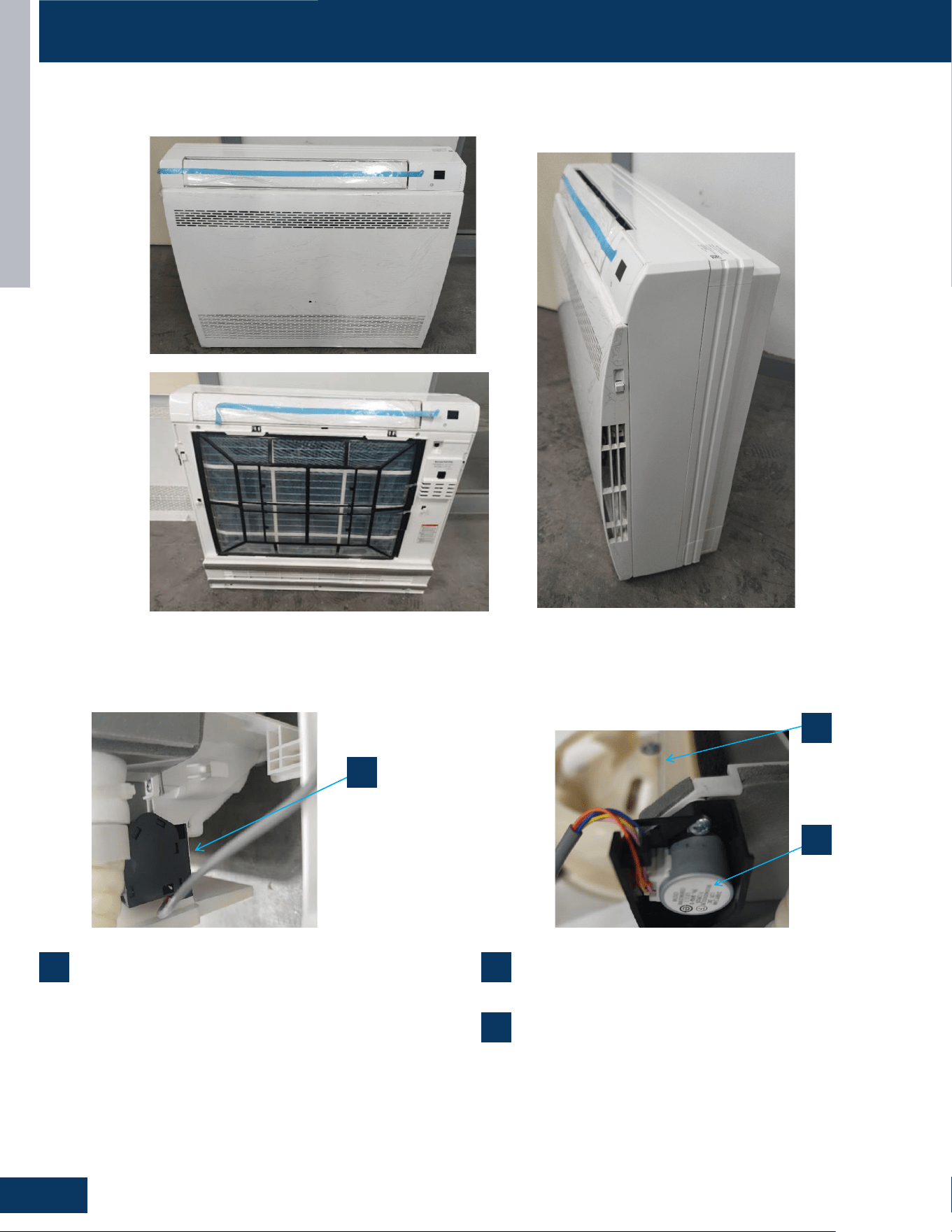
CONSOLE
E2
ENGLISH
COMPONENTS
US09FB2BEA / US12FB2BEA / US18FB2BEA
1
Louver Motor
The louver motors are stepper type motors that move the louvers
up/down. The motors are controlled by pulsed voltage that cannot
be measured. If the louver does not move when it should, check for a
bind in the louvers.
2
Flap
3
Step Motor
An electric device turning electrical pulses into precise mechanical
motions,rotatingaxedangleperpulse,usedforaccuratecontrol.
1
1
2
3
2
3
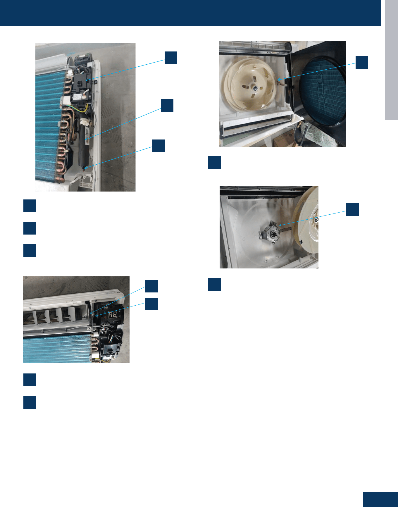
CONSOLE
E3
ENGLISH
COMPONENTS
4
Electrical Box
7
Flap
9
Fan Wheel
10
Fan Motor
5
Pipe Bushing
8
Fan Guard
6
Joint Connector
4
5
6
7
8
4
5
6
7
8
11
12
9
10
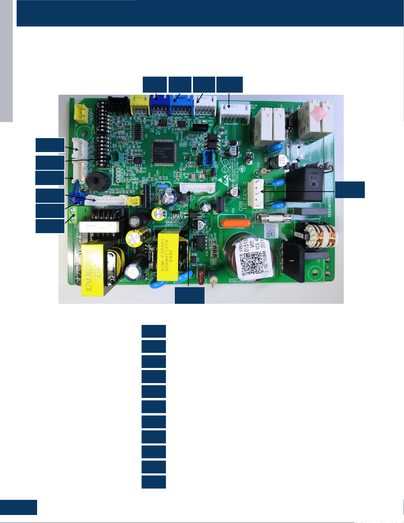
CONSOLE
E4
ENGLISH
COMPONENTS
PCB Overview
0151800987
US09FB2BEA / US12FB2BEA / US18FB2BEA
OTA
Refrigerant Sensor
Display Board
Sensor
Room Card
Left and Right Swing
Wired Controller
Fan Motor
WiFi
Power Supply
RJ45 Communication CN35 Up-and-Down Swing Motor
CN1
0151800987
US09FB2BEA US12FB2BEA US18FB2BEA
CN1
CN3
CN6
CN7
CN8
CN11
CN18
CN3
CN8
CN12
CN6
CN17
CN7
CN11
CN35
CN15
CN20
CN12
CN15
CN17
CN18
CN20
CN35
CN3 CN11 CN35 CN15
CN18
CN20
CN12
CN8
CN6
CN17
CN7
CN1
CN1
CN8
CN6
CN12
CN18
CN3
CN11
CN17
CN7
CN15
CN20
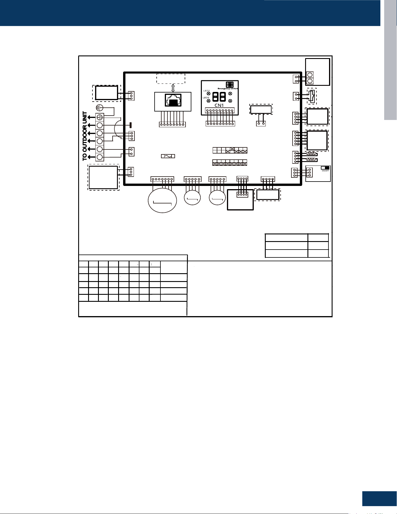
CONSOLE
E5
ENGLISH
WIRING DIAGRAM
US09FB2BEA / US12FB2BEA / US18FB2BEA
US09FB2BEA
Note :
1.Dashed parts are optional.
2.Please refer to the technical service manual for detailed explanations
of DI P switches.
3.Do not change the DI P switches setting without technical support
4.Abbreviation : R-red ,B-black,BL-blue, W -white,Y/G-yellow/green,
TEM P .-temperature, E.A.O-exrernal alarm output, T r-indoor unit
room temperature sensor ,Tp-indoor unit pipe temperature sensor (coil
temperature sensor)
W i r ed cont r oller
display(YR-E17)
07 flashing on the
upper right corner
Outdoor error code
+20 correspond HEX
code
SW1-1
OFF
OFF
SW1-2
OFF
OFF
OFF
OFF
OFF
OFF
OFF
OFF
OFF
OFF
OFF
ON
OFF
OFF
OFF
OFF
OFF OFF
ON
SW1-3
SW1-4
SW1-5 SW1-6
SW1-7 SW1-8
All Console
default
MODEL
DI P switches factory default setting
Note:
1.To get much more details about the out door unit failure,please refer tothe outdoor unit trouble
shooting list.
2.SW1-5OFF Start the refrigerant sensor function,SW1-5ON Disable the refrigerant sensor function
P anel
display
SW3-1
SW3-2 SW3-3
SW3-4
SW3-5 SW3-6
SW3-7 SW3-8
US12FB2BEA
US18FB2BEA
1 2 3
1 H 2 H
RD
BLK
WH
8 1 N C
H W
1 H C
1 N C
N R G
FRELAY FOR
FRESH AIR
MOTOR(dry
Contact,rating
-230VAC,3A)/
E.A.0
0 1 N C
H W
CN15
WH
M
DC FAN
CN35
WH
CN11
BLU
M
M
SWING2 SWING1
CN3
BLU
Air conditioning
refrigerant detector
Humidit y
Senso r
CN14
BLK
2 W S
L Y
T p
T r
7 N C
H W
I F I W A E G
E L U D O M
7 1 N C
H W
I F I W
E L U D O M
4 3 N C
H W
8 N C
m o o R
d r a C
U L B
UPPER/LOWER
OUTLET LOUVER
SELECTION SWITCH
BOARD
Centra l
Controlle r
3 1 N C
U L B
CN20
WH
RJ45 BOARD
T o RJ45 DEVICE
D E R I W
R E L L O R T N O C
Y
X
2 1 N C
N R G
1 W S
5 D E L
4 D E L
CN6
WH
DISPLAY BOARD
SW4
YL
Emergency
Stop
FUSE1
T6.3A/250VAC
Main cont r ol boa r d
BRN
RD
Y/G
Y/G
0150577395
OFF
OFF
OFF
ON SW1
ON SW3
bA
The refrigerant det-
ector is not installed
bA
No refrigerant detector is installed
AA
AA
Refrigerant leakage
Fault “AA” cannot be cleared. Only the
leakage concentration decreases and
the fault is turned to “Ab”.See the te-
chnical manual for elimination
Ac
Ac
The communication
of the refrigerant se-
nsor is faulty
When the air conditioner is running, t-
he cable harness of the refrigerant se-
nsor falls off.
Ad
Ad
The refrigerant sens-
or self-check is faulty
The refrigerant sensor is faulty.
AE
AE
Refrigerant sensor
life threshold
Refrigerant sensor life threshold rem-
inder
AF
AF
The refrigerant sens-
or expires
Refrigerant sensor life threshold, ne-
ed to be replaced
E1
E2
E4
F1-F45
01
02
04
07
0C
E7
E8
E12
E13
E14
0D
0E
Contents of Malfun-
ction
Malfunction of indoor
unit ambient tempera-
ture sensor
Malfunction of indoor-
unit piping temperatur-
e sensor
EEPROM wrong ofin-
door PCB
Abnormal communic-
ation between indoor
and outdoor units
Abnormal communic-
ation between wiredc-
ontroller and indoor
unit
Malfunction of drain-
system
Zero cross sigal wr-
ong
Indoor unit DC fanm-
otor abnormal
Outdoor unit error
Sensor disconected,or broken,or at
wrong position,orshort circuitsor.
Sensor disconected,or braken,or at
wrong position,orshort circuit.
EEPROM chip disconectedor broken
or wrong programmed,or PCB broken.
Wrong connection,or thewires be dis-
conected or wrong adress setting of
indoorunit or faulty power supplyor fa-
ulty PCB
Wrong connection or wiredcontroller
broken,or PCB faulty.
Pump motor disconnectedor at wrong
position,or thefloat switch,disconnec-
ted,or at wrong position, or theshort
circuit bridge disconneted
Zero cross sigal detected wrong.
DC Fan motor disconnectedor DC
Fan broken or circuitbroken
See correspond Outdoorunit error tro-
uble shooting.Remark: F1 means ou-
tdoor error code 1, F2 meansoutdoor
error code 2, andso on.
Possible reasons
OFF
OFF
OFF
OFF OFF OFF
OFF
OFF
1 N C
H W
SW1-5
Refrigerant Sensors
have
no
OFF
ON

[This page left intentionally blank]

MID-STATIC DUCTED
F1
ENGLISH
MID-STATIC DUCTED
US07MB2BEA
US09MB2BEA
US12MB2BEA
US18MB2BEA
US24MB2BEA
TABLE OF CONTENTS
COMPONENTS ....................................................................................................................................................................... F2
Evaporator Coil ....................................................................................................................................................................... F2
Blower Assembly .................................................................................................................................................................... F2
3 Terminal Block ...................................................................................................................................................................... F2
Control Board .......................................................................................................................................................................... F2
Ambient Temperature Sensor ...............................................................................................................................................F2
Piping Temperature Sensor ...................................................................................................................................................F2
Condensate Pump .................................................................................................................................................................. F3
Gravity Drain Ports ................................................................................................................................................................. F3
PCB Overview ......................................................................................................................................................................... F3
WIRING DIAGRAM ................................................................................................................................................................... F4
OUTDOOR/INDOOR WIRING CONNECTIONS
........................................................................................................................ F5
SERVICE PROCEDURES
.......................................................................................................................................................... F6
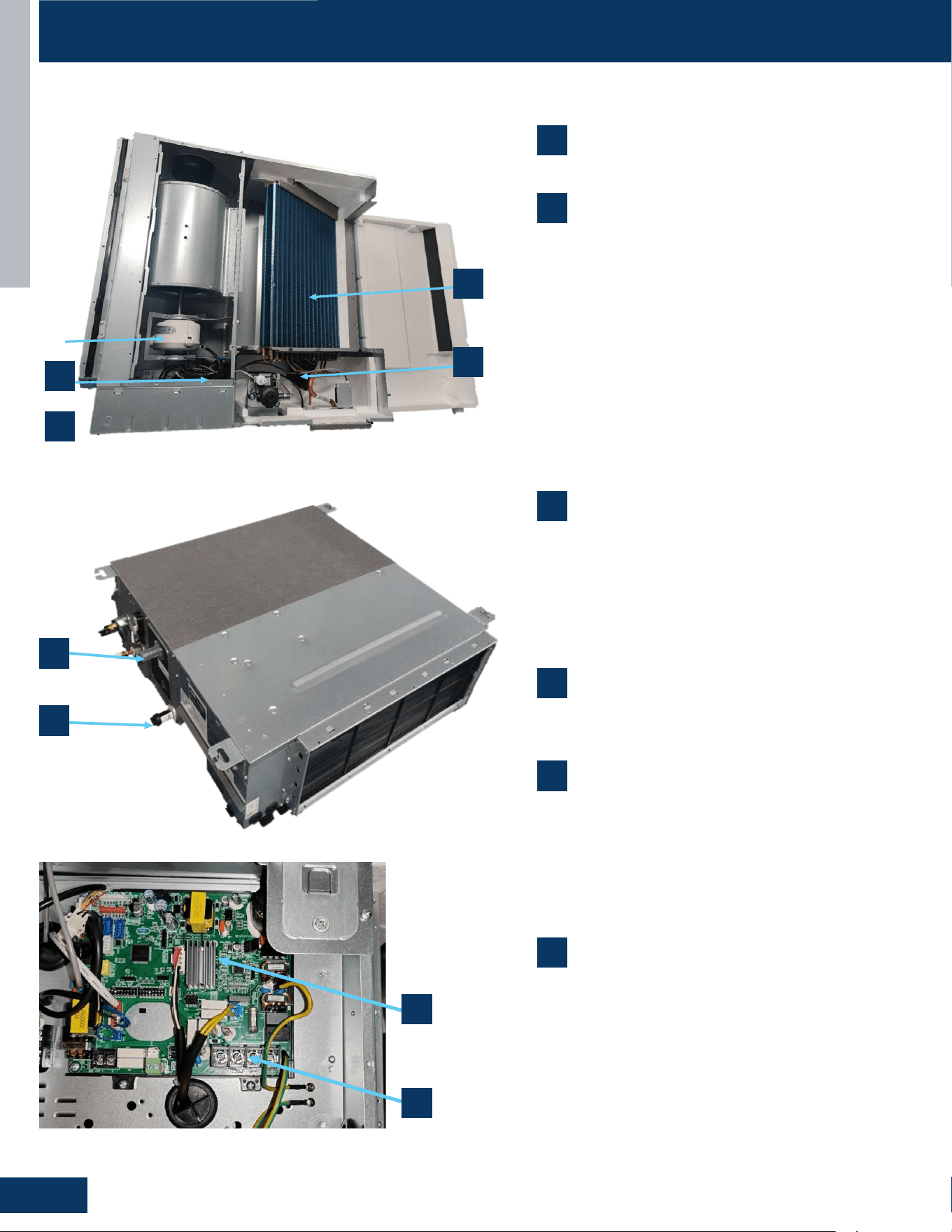
MID-STATIC DUCTED
F2
ENGLISH
COMPONENTS
US09MB2BEA / US12MB2BEA / US18MB2BEA / US24MB2BEA / US30MB2BEA
US36MB2BEA / US42MB2BEA / US48MB2BEA
7
8
2
1
5
6
7
8
7
8
2
1
5
6
2
5
1
6
1. Evaporator Coil
2. Blower Assembly
The indoor unit features a DC variable speed blower motor that will change speed to
match the capacity demand from the outdoor unit. The motor powers blower assembly.
The blower assembly consists of 2 plastic blowers. A set screw holds each blower wheel
to the blower motor.
The indoor blower motor is connected to the indoor unit control board. The wiring from
the motor to indoor board consists of 3 wires connected to pins that deliver line v
oltage.
During normal operation, the indoor control board will energize the indoor blower
motor and request proper speed.
3
. Terminal Block
Power to operate the indoor unit comes from the electrical line voltage terminal block at
the outdoor unit. The wiring includes 4 wires, 1, 2, S and ground. Wires 1 and S complete
the data path. These wires should always be
14
gauge
AWG
stranded
cooper,
non-
shielded
type wire. Splices in wires 1 or S may cause communication errors.
3
4
4
3
1
Evaporator Coil
2
Blower Assembly
The indoor unit features a DC variable speed blower motor
that will change speed to match the capacity demand from
the outdoor unit. The motor powers blower assembly.
The blower assembly consists of 2 plastic blowers. A set
screw holds each blower wheel to the blower motor.
The indoor blower motor is connected to the indoor unit
control board. The wiring from the motor to indoor board
consists of 3 wires connected to pins that deliver line
voltage.
During normal operation, the indoor control board will
energize the indoor blower motor and request proper
speed.
3
Terminal Block
Power to operate the indoor unit comes from the electrical
line voltage terminal block at the outdoor unit. The wiring
includes 4 wires, 1, 2, S and ground. Wires 1 and S complete
the data path. These wires should always be 14 gauge AWG
stranded cooper, non-shielded type wire. Splices in wires 1
or S may cause communication errors.
5
Ambient Temperature Sensor
The Ambient Temperature Sensor senses room
temperature. This sensor provides room temperature
information to the ECU for calculation of inverter capacity
and temperature control. Both sensors are negative
temperaturecoecienttypethatreduceelectrical
resistance as temperature rises.
6
Piping Temperature Sensor
The Piping Temperature Sensor senses indoor coil
temperature in the cooling mode and in the heating mode.
This sensor is used for Anti Freezing and Anti Cold Blow
cycles. The sensor also provides critical temperature
information to the ECU that may be used in frequency
adjustments.
4
Control Board
Located under the electrical control box cover.
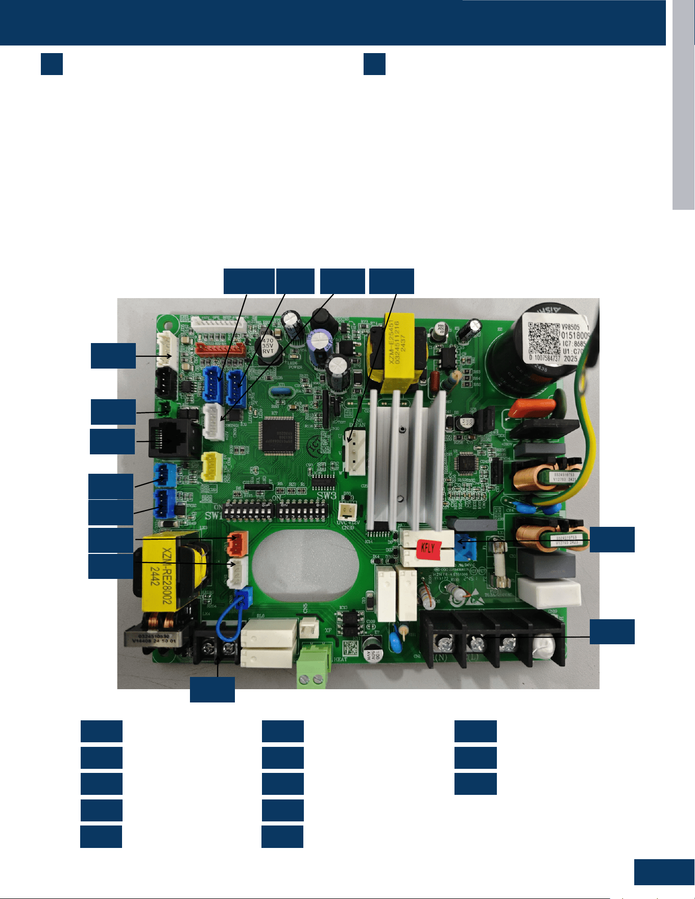
MID-STATIC DUCTED
F3
ENGLISH
COMPONENTS
US09MB2BEA / US12MB2BEA / US18MB2BEA / US24MB2BEA / US30MB2BEA / US36MB2BEA
7
Condensate Pump
The Duct unit has a built-in condensate pump. The pump is
connected to the circuit board. The pump is energized whenever
the Float Switch indicates that water needs to be pumped from the
cassette.Theoatswitchconnectsontothecircuitboard.
Theoatswitchandpumparelocatedbehindtheremovable
insulated cover next to the electrical control box. The pump is
hermeticallysealedandrequiresnomaintenance.Theoatswitchis
anormallyclosedswitch,thatopensaswaterrises.Theoatswitch
requires no maintenance.
8
Gravity Drain Ports
The indoor units have the option for either gravity drain systems or
theuseofaninternalcondensatepumpwithoatswitch.Ifhighlift
isrequired,thewaterfromtheductunitshouldbepumpedtoaeld
condensate pump that is capable of high lift.
Power Supply
OTA
Refrigerant Sensor
Drain Pump
Fan Motor
Wired Controller
Remote Communication
Up-and-Down Swing
Float Switch
WiFi
RJ45 Communication
Left and Right Swing
Sensor
PCB Overview
0151800986
US09MB2BEA US12MB2BEA US18MB2BEA US24MB2BEA US30MB2BEA US36MB2BEA US42MB2BEA US48MB2BEA
CN1
CN2
CN3
CN4
CN6
CN7
CN9
CN41
CN4
CN1
CN7
CN13
CN3
CN9
CN17
CN2
CN15
CN11-1
CN6
CN11
CN35
CN11
CN11-1
CN13
CN15
CN17
CN35
CN41
CN11-1 CN11 CN35
CN15
CN4
CN1
CN2
CN7
CN17
CN9
CN3
CN13
CN41
CN6
CN1 CN7 CN17
CN2 CN9 CN35
CN3
CN11-1
CN41
CN4 CN13
CN6 CN15
0151800986
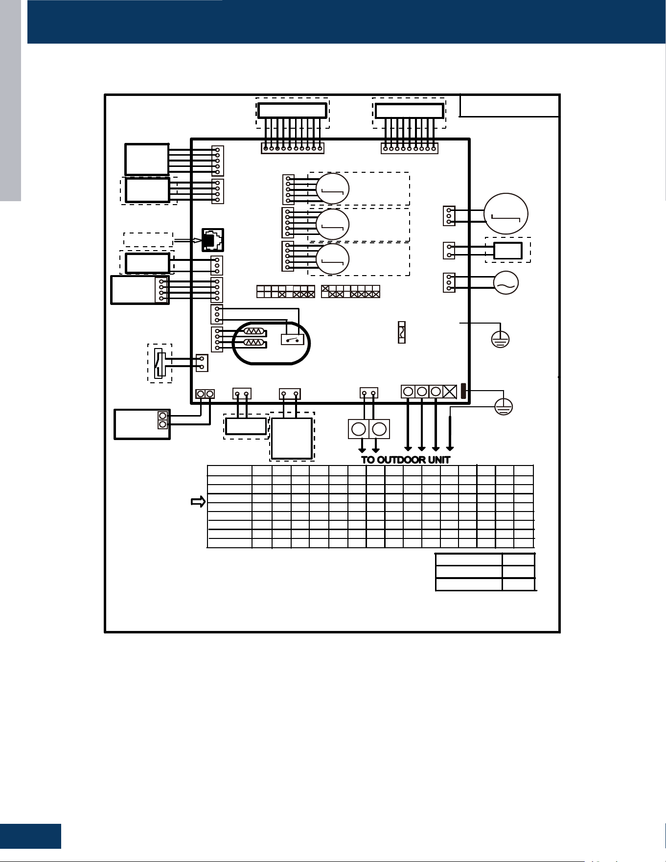
MID-STATIC DUCTED
F4
ENGLISH
WIRING DIAGRAM
US09MB2BEA / US12MB2BEA / US18MB2BEA / US24MB2BEA / US30MB2BEA / US36MB2BEA
Factory default setting
of the DIP switches
SW1-1 SW1-2 SW1-3 SW1-4 SW1-6 SW1-7 SW1-8 SW3-1 SW3-2 SW3-3 SW3-4 SW3-5 SW3-6 SW3-7 SW3-8
US09MB2BEA
MODEL
OFF OFF OFF OFF OFF OFF OFF ON OFF OFF OFF OFF OFF OFF
ON
0150577393
OFF OFF OFF OFF OFF OFF OFF OFF OFF OFF OFF OFF
ON
OFF OFF OFF OFF OFF OFF OFF OFF OFF OFF
ON
OFF
ON ON
OFF OFF OFF OFF OFF OFF OFF OFF OFF OFF
ON
ON
US12MB2BEA
US18MB2BEA
US24MB2BEA
US30MB2BEA
ON
OFF
OFF
OFF OFF OFF F OFF
ON
OF
OFF
OFF OFF OFF
OFF
OFF
ON
OFF
1ESUF
CAV052/A3.6T
CN1
1(N) 2(L) 3(S)
AC PUMP
MOTOR
CN7
YL
YL
4NC
WIRED
CONTROLLER
ULB
Y/G
91NC
Y X
X Y
1 2 3
CN20
61NC
ROOM CARD
ULB
HW
14NC
Tp
Tr
31NC
FLOAT SWITCH
TO RJ45 device
3NC9NC
DR
Air conditioning
refrigerant detector
ULB
Central Controller
51NC
41NC
71NC
WIFI MODULE
Humidity Sensor
CN5
WH
FRELAY FOR
FRESH AIR
MOTOR(dry
Contact,rating
-230VAC,3A)/
E.A.0
M
UVC
93NC
HW
6NC
HW
M
DC FAN
ON SW1 ON
SW3
M
M
M
11NC1-11NC53NC
HW
ULB
ULB
KLB
Swing Motor2
Swing Motor3
Swing Motor1
LED DISPLAY
Display PCB
GRN
KLBHW
ULB
CN21
WH
CN31
RD
FRELAY FOR
Electric Heater
H1 H2
CN2
GRN
NOTE:
1.Dashed
parts are opt
ional.
2.Please refer to service manual to get details of the DIP switches definition .
3.Do not change the DIP switches setting without technical support.
4.Get details from trouble shooting list about LED indication.
5.Abbreviation
:
RD -red, W-withe, BLK-black,BLU-blue,GRN-green,YL-yellow,Y/G-yellow/green,E.A.O:
external alarm output,Tr
:
indoor unit ambient(room) temperature sensor,Tp
:
indoor unit pipe(coil)
temperatur
e
sensor.
6.The port CN10&CJ1&CJ2&CN22&P5 are dry contact output port for
particular use,do not connect other device without technical person support.
US36MB2BEA
US42MB2BEA
US48MB2BEA
OFF OFF OFF OFF OFF OFF OFF OFF OFF OFF OFF
OFF ON OFF OFF OFF OFF OFF OFF OFF OFF OFF OFFON
OFF OFF OFF OFF OFF OFF OFF OFF OFFON
ON
OFF
ON ON
ON
ON ON ON
Y/G
CON1
Wired
controller
display
07 flashing
on the upper
right corner
Outdoor error
code +20 cor-
respond HEX
code
Note:
1.To get much more details about the out door unit failure,please refer tothe outdoor unit trouble
shooting list.
2.SW1-5OFF Start the refrigerant sensor function,SW1-5ON Disable the refrigerant sensor function
Panel
display
bA
The refrigerant det-
ector is not installed
bA
No refrigerant detector is installed
AA
AA
Refrigerant leakage
Fault “AA” cannot be cleared. Only the
leakage concentration decreases and
the fault is turned to “Ab”.See the te-
chnical manual for elimination
Ac
Ac
The communication
of the refrigerant se-
nsor is faulty
When the air conditioner is running, t-
he cable harness of the refrigerant se-
nsor falls off.
Ad
Ad
The refrigerant sens-
or self-check is faulty
The refrigerant sensor is faulty.
AE
AE
Refrigerant sensor
life threshold
Refrigerant sensor life threshold rem-
inder
AF
AF
The refrigerant sens-
or expires
Refrigerant sensor life threshold, ne-
ed to be replaced
E1
E2
E4
F1-F45
01
02
04
07
0C
E7
E8
E12
E13
E14
0D
0E
Contents of Malfun-
ction
Malfunction of indoor
unit ambient tempera-
ture sensor
Malfunction of indoor-
unit piping temperatur-
e sensor
EEPROM wrong ofin-
door PCB
Abnormal communic-
ation between indoor
and outdoor units
Abnormal communic-
ation between wiredc-
ontroller and indoor
unit
Malfunction of drain-
system
Zero cross sigal wr-
ong
Indoor unit DC fanm-
otor abnormal
Outdoor unit error
Sensor disconected,or broken,or at
wrong position,orshort circuitsor.
Sensor disconected,or braken,or at
wrong position,orshort circuit.
EEPROM chip disconectedor broken
or wrong programmed,or PCB broken.
Wrong connection,or thewires be dis-
conected or wrong adress setting of
indoorunit or faulty power supplyor fa-
ulty PCB
Wrong connection or wiredcontroller
broken,or PCB faulty.
Pump motor disconnectedor at wrong
position,or thefloat switch,disconnec-
ted,or at wrong position, or theshort
circuit bridge disconneted
Zero cross sigal detected wrong.
DC Fan motor disconnectedor DC
Fan broken or circuitbroken
See correspond Outdoorunit error tro-
uble shooting.Remark: F1 means ou-
tdoor error code 1, F2 meansoutdoor
error code 2, andso on.
Possible reasons
Indoor unit trouble shooting
LED9 flash times
Tens
place
Ones
place
0
1
0
0
0
0
0
0
0
2
4
7
8
12
13
14
M(≥2)
N(≥0)
18
6
17
0
17
2
17
3
17
4
17
5
RD
BRN
SW1-5
Refrigerant Sensors
have
no
OFF
ON
ON
ON
ON
ON
ON
ON
ON
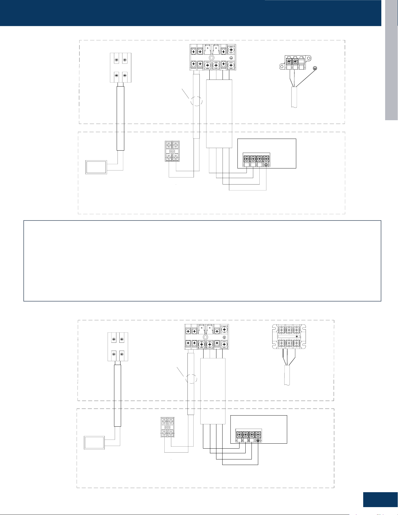
MID-STATIC DUCTED
F5
ENGLISH
Power Supply
1Ph,208/230V,60Hz
L1(N)
Indoor Unit --DUCT
Power
@2
@1
These communication
cable should be shielded
twisted pair type.
Outdoor Unit
Communication cable for indoor unit and outdoor unit,4*2.5mm²
Caution
:
①
The OTA communication cable should be shielded twisted pair type,
and need to make the cable's shielded layer connect to earth or the unit
shell which connect to earth (indoor side or outdoor side).
②
There should be independent pipeline for communication wire.
③
The distance between OTA communication cable and the power supply
cable should be at least 10cm.
④
Ensure specifically that there is an earth leakage breaker (ELB)
installed for both the outdoor and indoor unit.
⑤
If the installation is already fitted with an earth leakage breaker (ELB),
ensure that its rated current is large enough to withstand the current of the
units (both outdoor and indoor).
@3:
@1:
@2:
Communication cable for central controller, wire specification to
refer to wired controller manual and real installation length.
@4:
The OTA communication cable (H1/H2) should be 2 x 16 AWG
shielded.
Indoor Unit
PCB
Power supply cable, 3*4mm² for 9k/12k/18k/24k/36k,3*6mm² for
42k/48k
C1 C2
@4
H1
@3
B
A
Central
Controller
H2
L1
L2
L2(L)
H1
H2 1
2
3
S
OUTDOOR/INDOOR WIRING CONNECTIONS
US24MB2BEA
Caution:
1. The OTA communication cable should be shielded twisted pair type, and need to make the cable’s shielded layer connect to earth or the unit shell which
connect to earth (indoor side or outdoor side).
2. There should be independent pipeline for communication wire.
3. The distance between OTA communication cable and the power supply cable should be at least 10cm.
4. Ensurespecicallythatthereisanearthleakagebreaker(ELB)installedforboththeoutdoorandindoorunit.
5. Iftheinstallationisalreadyttedwithanearthleakagebreaker(ELB),ensurethatitsratedcurrentislargeenoughtowithstandthecurrentoftheunits(both
outdoor and indoor).
@1 Power supply cable, 3*4mm² for 9k/12k/18k/24k/36k,3*6mm² for 42k/48k
@2 Communication cable for indoor unit and outdoor unit,4*2.5mm²
@3Communicationcableforcentralcontroller,wirespecicationtorefertowiredcontrollermanualandrealinstallationlength.
@4 The OTA communication cable (H1/H2) should be 2 x 16 AWG shielded.
US30MB2BEA / US36MB2BEA
Indoor Unit --DUCT
@2
These communication
cable should be shielded
twisted pair type.
Outdoor Unit
Communication cable for indoor unit and outdoor unit,4*2.5mm²
Caution
:
①
The OTA communication cable should be shielded twisted pair type,
and need to make the cable's shielded layer connect to earth or the unit
shell which connect to earth (indoor side or outdoor side).
②
There should be independent pipeline for communication wire.
③
The distance between OTA communication cable and the power supply
cable should be at least 10cm.
④
Ensure specifically that there is an earth leakage breaker (ELB)
installed for both the outdoor and indoor unit.
⑤
If the installation is already fitted with an earth leakage breaker (ELB),
ensure that its rated current is large enough to withstand the current of the
units (both outdoor and indoor).
@3:
@1:
@2:
Communication cable for central controller, wire specification to
refer to wired controller manual and real installation length.
@4:
The OTA communication cable (H1/H2) should be 2 x 16 AWG
shielded.
Indoor Unit
PCB
Power supply cable, 3*4mm² for 9k/12k/18k/24k/36k,3*6mm² for
42k/48k
C1 C2
@4
H1
@3
B
A
Central
Controller
H2
Power Supply
1Ph,208/230V,60Hz
Power
@1
L1(N) L2(L)
H1
H2 1
2
3
S
L1
L2
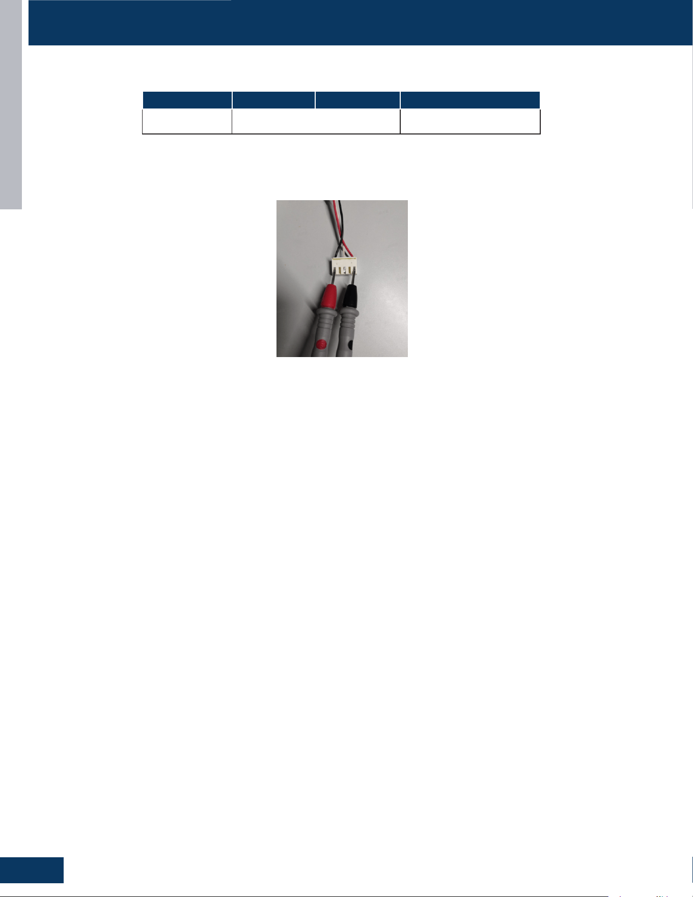
MID-STATIC DUCTED
F6
ENGLISH
SERVICE PROCEDURES
Resistance Values
Measure the Resistance :
Use a multimeter to measure the resistance between any two phases (U, V, W) of the motor (as shown in the following diagram).
Model US09MB2BEA US12MB2BEA US18MB2BEA
Fan Motor Model
Resistance Value
0150401249C, 20.6±7% 0150402221C, 12.5±7%

TROUBLESHOOTING AND REFERENCE
G1
ENGLISH
TROUBLESHOOTING AND REFERENCE
TABLE OF CONTENTS
ERROR CODES ........................................................................................................................................................................G2
ErrorCodeLEDandJumpWireIdentication ..................................................................................................................... G6
OUTDOOR UNIT DIP SWITCH SETTINGS ...............................................................................................................................G7
INDOOR UNIT DIP SWITCH SETTINGS
.................................................................................................................................G10
SENSOR RESISTANCE TABLES
..............................................................................................................................................G12
ERROR CODE TROUBLESHOOTING
......................................................................................................................................G18
[1] ......................................................................................................................................................................................... G18
[2] ........................................................................................................................................................................................ G18
[4] ......................................................................................................................................................................................... G18
[6] ......................................................................................................................................................................................... G19
[8] ......................................................................................................................................................................................... G19
[9] ......................................................................................................................................................................................... G20
[10] ...................................................................................................................................................................................... G20
[11] ...................................................................................................................................................................................... G20
[12] ....................................................................................................................................................................................... G20
[13] ...................................................................................................................................................................................... G20
[15] ..................................................................................................................................................................................... G21
[16] ...................................................................................................................................................................................... G22
[17] ...................................................................................................................................................................................... G22
[18] ...................................................................................................................................................................................... G23
[24] ...................................................................................................................................................................................... G23
[25] ...................................................................................................................................................................................... G23
[42] ...................................................................................................................................................................................... G24
[43] ...................................................................................................................................................................................... G25
[44] ...................................................................................................................................................................................... G26
[45] ...................................................................................................................................................................................... G26
E1/LED1: No Flash ............................................................................................................................................................... G27
E2/LED1: No Flash .............................................................................................................................................................. G27
E4 ......................................................................................................................................................................................... G28
E14 ....................................................................................................................................................................................... G28
E7/LED1: 15 Flash ............................................................................................................................................................... G29
LED1: 21Flash ...................................................................................................................................................................... G30
LED1: 28Flash ...................................................................................................................................................................... G30
E22/LED1: 21 Flash ............................................................................................................................................................. G31
F27/LED1: 21 Flash ............................................................................................................................................................. G31
bA ......................................................................................................................................................................................... G32
AA and Ab ............................................................................................................................................................................. G33
Ac ......................................................................................................................................................................................... G34
Ad ......................................................................................................................................................................................... G35
AE ......................................................................................................................................................................................... G36
AF ......................................................................................................................................................................................... G36
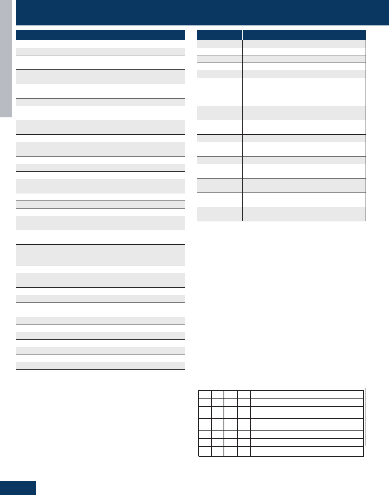
TROUBLESHOOTING AND REFERENCE
G2
ENGLISH
ERROR CODES
PRODUCT DIAGNOSIS PROCEDURE
Malfunction
Code
Diagnosis
Malfunction
Code
Diagnosis
IPM overcurrent or short circuit
Module operated overload (compressor overload protection)
Module low or high voltage
Communication failure between the IPM and outdoor PCB
9
10
1
2
4
5
6
Malfunction of defrost temperature sensor
Outdoor EEPROM failure
Malfunction of the DC fan motor
Diagnosis using the Numeral LED Indicator
Notes:
1. Setting of indoor address is not required.
2. Connecting wire between indoor and
outdoor is polarized. Switching wires
betweenindoor & outdoor connection
position 1/ 2 /3(C) /G will result in
communication failure.
3.Quiet Operation setting (SW5-8 ON) will
lower outdoor noise level. It will also
reduce operating capacity slightly.
4.Do not change the DIP switches setting
without technical support.See service
manual for other dipswitch settings.
Improperly set switch may cause damage
or other malfunctions.
5.For some particular protection type
malfunctions, this system can back to
.
* MCB:Main control board
* MCU:Micro Control Unit (main chip
in the module board)
* IDU:Indoor unit
* EEV:Electro expansion valve
OFF OFF OFF OFF
ON OFF OFF OFF
OFF ON OFF OFF
OFF OFF ON OFF
1 2 3 4
Definition of service display SW1
Normal Operating(default)
Manually forced Heating:compressor 50rps;
*
EEV 200pls;ODU fan motor speed high
Rated Operating(fixed speed)
OFF OFF ONOFF
Time Defrost Valid
Manually forced Cooling:compressor 60rps;
EEV 200pls;ODU fan motor speed high
ON
ON ON ON
IDU&ODU Wiring Error Check valid
running after first or second Re-try.
* ODU:Outdoor unit
6. Other detailed service information
please refer to technical service mannual.
0150578033
3
Outdoor alternating current, over current protection
Compressor current sampling circuit fault
7
Overheat protection for discharge temperature
8
11
Suction temperature sensor failure
12
Ambient temperature sensor failure
13
Discharge temperature sensor failure
15
Communication failure between the indoor & outdoor unit
16
Lack of refrigerant or discharging
17
4-way valve switching failure
18
Loss of synchronism detection
19
Position detection circuit fault of compressor
20
Power supply side hardware instantaneous overcurrent
21
Indoor thermal overload (Indoor thermal overload & Indoor
anti-frosting protection)
23
Module thermal overload
24
Compressor start failure, over-current
25
Phase current protection (IPM)
26
MCU reset
27
Module current detect circuit malfunction
28
Malfunction of Liquid pipe sensor failure: Circuit A
29
Malfunction of Liquid pipe sensor failure: Circuit B
30
Malfunction of Liquid pipe sensor failure: Circuit C
31
Malfunction of Liquid pipe sensor failure: Circuit D
32
Malfunction of Gas pipe sensor failure: Circuit A
33
Malfunction of Gas pipe sensor failure: Circuit B
34
Malfunction of Gas pipe sensor failure: Circuit C
35
Malfunction of Gas pipe sensor failure: Circuit D
36
Malfunction of Liquid pipe sensor failure: Circuit E
38
Malfunction of module temperature sensor momentary
power failure detection
39
Malfunction of condensing temperature sensor
40
42
High Pressure switch open
43
Low Pressure switch open
44
System high pressure protection: Overcharged, high
condensing temperature or malfunction of fan motor.
45
System low pressure protection: Undercharged, low
defrosting temperature, or malfunction of fan motor.
46
The temperature sensor of the driver board is abnormal
71
Low outdoor ambient temperature alarm
AA
AB
Refrigerant sensor leaks
AC
The communication of the refrigerant sensor is abnormal
AD
The refrigerant sensor self-check is faulty
AF
The refrigerant sensor service life expires
BA
The refrigerant sensor has no dip switchbreakdown
Malfunction of Gas pipe sensor failure: Circuit E
50
Three-phase power supply phase loss fault
53
Module startup failed
ERROR CODE FAULT DESCRIPTION
1 OUTDOOR EEPROM FAILURE
2 IPM OVERCURRENT OR SHORT CIRCUIT
3
OUTDOOR ALTERNATING CURRENT, OVER
CURRENT PROTECTION
4
COMMUNICATION FAILURE BETWEEN THE IPM
AND OUTDOOR PCB
5
MODULE OPERATED OVERLOAD
(COMPRESSOR OVERLOAD PROTECTION)
6 MODULE LOW OR HIGH VOLTAGE
7
COMPRESSOR CURRENT SAMPLING CIRCUIT
FA U LT
8
OVERHEAT PROTECTION FOR DISCHARGE
TEMPERATURE
9 MALFUNCTION OF THE DC FAN MOTOR
10
MALFUNCTION OF DEFROST TEMPERATURE
SENSOR
11 SUCTION TEMPERATURE SENSOR FAILURE
12 AMBIENT TEMPERATURE SENSOR FAILURE
13 DISCHARGE TEMPERATURE SENSOR FAILURE
15
COMMUNICATION FAILURE BETWEEN THE
INDOOR & OUTDOOR UNIT
16 LACK OF REFRIGERANT OR DISCHARGING
17 4-WAY VALVE SWITCHING FAILURE
18 LOSS OF SYNCHRONISM DETECTION
19
POSITION DETECTION CIRCUIT FAULT OF
COMPRESSOR
20
POWER SUPPLY SIDE HARDWARE
INSTANTANEOUS OVERCURRENT
21
INDOOR THERMAL OVERLOAD (INDOOR
THERMAL OVERLOAD & INDOOR ANTI-
FROSTING PROTECTION)
23 MODULE THERMAL OVERLOAD
24
COMPRESSOR START FAILURE, OVER-
CURRENT
25 PHASE CURRENT PROTECTION (IPM)
26 MCU RESET
27
MODULE CURRENT DETECT CIRCUIT
MALFUNCTION
28 LIQUID PIPE SENSOR FAILURE: CIRCUIT A
29 LIQUID PIPE SENSOR FAILURE: CIRCUIT B
30 LIQUID PIPE SENSOR FAILURE: CIRCUIT C
31 LIQUID PIPE SENSOR FAILURE: CIRCUIT D
32 GAS PIPE SENSOR FAILURE: CIRCUIT A
33 GAS PIPE SENSOR FAILURE: CIRCUIT B
34 GAS PIPE SENSOR FAILURE: CIRCUIT C
35 GAS PIPE SENSOR FAILURE: CIRCUIT D
ERROR CODE FAULT DESCRIPTION
36 GAS PIPE SENSOR FAILURE: CIRCUIT E
39 CONDENSING TEMPERATURE SENSOR
40 LIQUID PIPE SENSOR FAILURE: CIRCUIT E
42 HIGH PRESSURE SWITCH OPEN
43 LOW PRESSURE SWITCH OPEN
44
SYSTEM HIGH PRESSURE PROTECTION:
OVERCHARGED, HIGH CONDENSING
TEMPERATURE OR MALFUNCTION OF FAN
MOTOR.
46
THE TEMPERATURE SENSOR OF THE DRIVER
BOARD IS ABNORMAL
50
THREE-PHASE POWER SUPPLY PHASE LOSS
FA U LT
53 MODULE STARTUP FAILED
71
LOW OUTDOOR AMBIENT TEMPERATURE
ALARM
AA AB REFRIGERANT SENSOR LEAK DETECTED
AC
THE COMMUNICATION OF THE REFRIGERANT
SENSOR IS ABNORMAL
AD
THE REFRIGERANT SENSOR SELF-CHECK IS
FA U LT Y
AF
THE REFRIGERANT SENSOR SERVICE LIFE
EXPIRES
BA
THE REFRIGERANT SENSOR HAS NO DIP
SWITCH BREAKDOWN
• EEV: Electronic expansion valve
• MCB: Main control board
• ODU: Outdoor unit
• MCU: Micro Control Unit (main chip in the module board)
IDU: Indoor unit
Notes:
1. Setting of indoor address is not required.
2. Connecting wire between indoor and outdoor is polarized.
Switching wires between indoor & outdoor connection position 1/
2 /3 (C)/G will result in communication failure.
3. Quiet Operation setting (SW5-8 ON) will lower outdoor noise
level. It will also reduce operating capacity slightly.
4. Do not change the DIP switches setting without technical
support. See service manual for other dipswitch settings.
Improperly set switch may cause damage or other malfunctions.
5. For some particular protection type malfunctions, this system can
retry up to three times before generating a fault code

TROUBLESHOOTING AND REFERENCE
G3
ENGLISH
ERROR CODES
Error Code 3
Compressor drive module DC input over current DC input over
current been detected by compressor drive module or input current
higher than main board setting. Before replacing the IPM, check
these potential causes of high current:
• Overcharge
• Dirty outdoor coil when cooling
• Hot conditioned space
• High temperature or excessive load
• Refrigeration circuit restriction
• Seized compressor
• Faulty wiring or wiring connections
• Thelteroftheindoorunitisdirtyduringheating
• The indoor fan motor in the heating mode is faulty
Error Code 5/20
The IPM is protecting the compressor from overload, which can be
caused by low building power supply, restrictions, a non-condensible
in the system, a plugged coil, an excessive load, or a refrigerant
overcharge.
Error Code 7
This code indicates that the compressor is locked or has an instant
stop. This fault is detected by the compressor frequency conversion
module as a phase loss in the input power of the three-phase
module. After the compressor frequency conversion module makes
its own judgment, it sends the module fault code to the outdoor
electrical controller through the communication port. This fault is
not locked and can be automatically restored after the module fault is
resolved.
Error Code 19
This code indicates a fault in the position detection circuit. This fault
is caused by a current sampling circuit failure in the compressor
frequency conversion module. The compressor frequency
conversion module determines it by itself and sends the module fault
code to the outdoor electric controller through the communication
port, or it detects a fault in the input current sampling circuit of the
compressor frequency conversion module and determines it by itself,
sending the module fault code to the outdoor electric controller
through the communication port.
Error Code 20
This code indicates the operating voltage of the system is too low
.check line voltage for proper limits. A sudden voltage drop resulting
in over-current triggers this failure.
Error Code 23
This code indicates an IPM thermal overload. This error was
generated by a temperature sensor located in the IPM heat sink.
Causes of overheating are typically overcharge of refrigerant,
excessively plugged coil, sensor open or shorted, or a non-
condensable in system.
Error Code 26
Module reset indicates possible PCB power anomalies. This usually
occurs when low line voltage conditions are present.
Error Code 27
The IPM has detected that the compressor current is too high.
Possible Causes:
• Overcharge
• Dirty outdoor coil
• Hot conditioned space temperature or high load
• Refrigeration circuit restriction
• Seized compressor
• Defective IPM
Error Code 28/29/30/31/40
Thiscodeindicatesthatthesamplingresistanceofthenetubes
of the A/B/C/D/E unit is abnormal. This sensor is used to detect
thetemperatureofthenetubesoftheindoorunit.Whenthe
temperature sensor is short-circuited or open-circuited for one
minute, a fault is reported. It is necessary to check whether this
sensor is short-circuited or short-circuited. If there is a problem, the
CN1 sensor needs to be replaced.
Error Code 32/33/34/35/36
This code indicates that the sampling resistance of the thick tube
of the A/B/C/D/E unit is abnormal. This sensor is used to detect
the temperature of the thin tube of the indoor unit. When the
temperature sensor is short-circuited or open-circuited for one
minute, a fault is reported. It is necessary to check whether this
sensor is short-circuited or short-circuited. If there is a problem, the
CN24 sensor needs to be replaced.
Error Code 38
This code indicates a module failure: an unknown failure. When the
frequencyconversionmodulesendsanunidentiablefaultcode,a
failure is reported.
Error Code 39
This code indicates an electrical failure of Tc sensor that is used to
sense the condensing temperature of the outdoor coil. The sensor is
connected to the PCB via wires at Plug CN-14.
Error Code 46
Compressor driver module heat sink sensor abnormal. The
compressor driver module heat sink sensor temperature short circuit
or open circuit
• PCB fault
• Outside temperature is below -35°C.
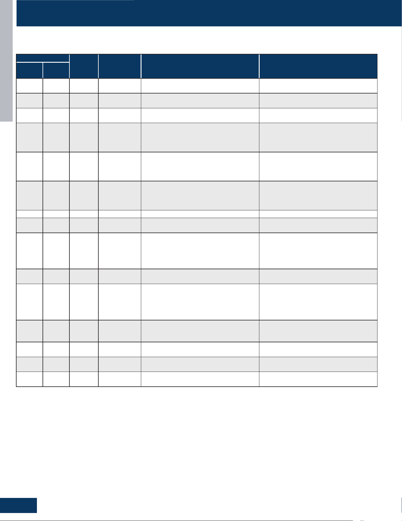
TROUBLESHOOTING AND REFERENCE
G4
ENGLISH
US09CB2BEA / US12CB2BEA / US18CB2BEA / US24LB2BEA / US30LB2BEA / US36LB2BEA
US09MB2BEA / US12MB2BEA / US18MB2BEA / US24MB2BEA / US30MB2BEA / US36MB2BEA
ERROR CODES
LED2 FLASH TIMES
PANEL
DISPLAY
WIRED
CONTROLLER
DISPLAY
DESCRIPTION POSSIBLE CAUSES
TENS
PLACE
ONES
PLACE
0 1 E1 1
INDOOR UNIT AMBIENT TEMPERATURE
SENSOR MALFUNCTION
SENSOR DISCONNECTED, BROKEN, AT
WRONG POSITION, OR SHORT CIRCUIT.
0 2 E2 2
INDOOR UNIT PIPING TEMPERATURE
SENSOR MALFUNCTION
SENSOR DISCONNECTED, BROKEN, AT
WRONG POSITION, OR SHORT CIRCUIT.
0 4 E4 4 INDOOR PCB EEPROM WRONG
EEPROM CHIP DISCONNECTED, BROKEN,
WRONG PROGRAMMED, OR PCB BROKEN.
0 7 E7 7
ABNORMAL COMMUNICATION BETWEEN
INDOOR AND OUTDOOR UNITS
WRONG CONNECTION, WIRES
DISCONNECTED, WRONG ADDRESS
SETTING OF INDOOR UNIT, FAULTY POWER
SUPPLY, OR FAULTY PCB
0 8 E8
07 FLASHING
ON THE
UPPER RIGHT
CORNER
ABNORMAL COMMUNICATION BETWEEN
WIRED CONTROLLER AND INDOOR UNIT
WRONG CONNECTION, WIRED
CONTROLLER BROKEN, OR PCB FAULTY.
0 12 E12 0C DRAIN SYSTEM MALFUNCTION
PUMP MOTOR DISCONNECTED OR
AT WRONG POSITION,FLOAT SWITCH
DISCONNECTED, WRONG POSITION, OR
SHORT CIRCUIT BRIDGE DISCONNECTED
0 13 E13 0D ZERO CROSS SIGNAL WRONG ZERO CROSS SIGNAL DETECTED WRONG.
0 14 E14 0E INDOOR UNIT DC FAN MOTOR ABNORMAL
DC FAN MOTOR DISCONNECTED, FAN
BROKEN, OR CIRCUIT BROKEN
M(≥2) N(≥0) F1-F45
OUTDOOR
ERROR
CODE +20
CORRESPOND
HEX CODE
OUTDOOR UNIT ERROR
SEE CORRESPOND OUTDOOR UNIT ERROR
TROUBLESHOOTING. REMARK: F1 MEANS
OUTDOOR ERROR CODE 1, F2 MEANS
OUTDOOR ERROR CODE 2, AND SO ON.
18 6 bA BA
THE REFRIGERANT DETECTOR IS NOT
INSTALLED
NO REFRIGERANT DETECTOR IS INSTALLED
17 0 AA AA REFRIGERANT LEAKAGE
FAULT “AA” CANNOT BE CLEARED.
ONLY THE LEAKAGE CONCENTRATION
DECREASES AND THE FAULT IS TURNED
TO “AB”. SEE THE TECHNICAL MANUAL FOR
ELIMINATION
17 2 Ac AC
THE COMMUNICATION OF THE
REFRIGERANT SENSOR IS FAULTY
WHEN THE AIR CONDITIONER IS
RUNNING, THE CABLE HARNESS OF THE
REFRIGERANT SENSOR FALLS OFF.
17 3 Ad AD
THE REFRIGERANT SENSOR SELF CHECK IS
FA U LT Y
THE REFRIGERANT SENSOR IS FAULTY.
17 4 AE AE REFRIGERANT SENSOR LIFE THRESHOLD
REFRIGERANT SENSOR LIFE THRESHOLD
REMINDER
17 5 AF
AF THE REFRIGERANT SENSOR EXPIRES
REFRIGERANT SENSOR LIFE THRESHOLD,
NEED TO BE REPLACED
Note:
1. For more details about the outdoor unit failure, please refer to the outdoor unit troubleshooting list.
2. SW1-5 OFF: Start the refrigerant sensor function. SW1-5 ON: Disable the refrigerant sensor function.
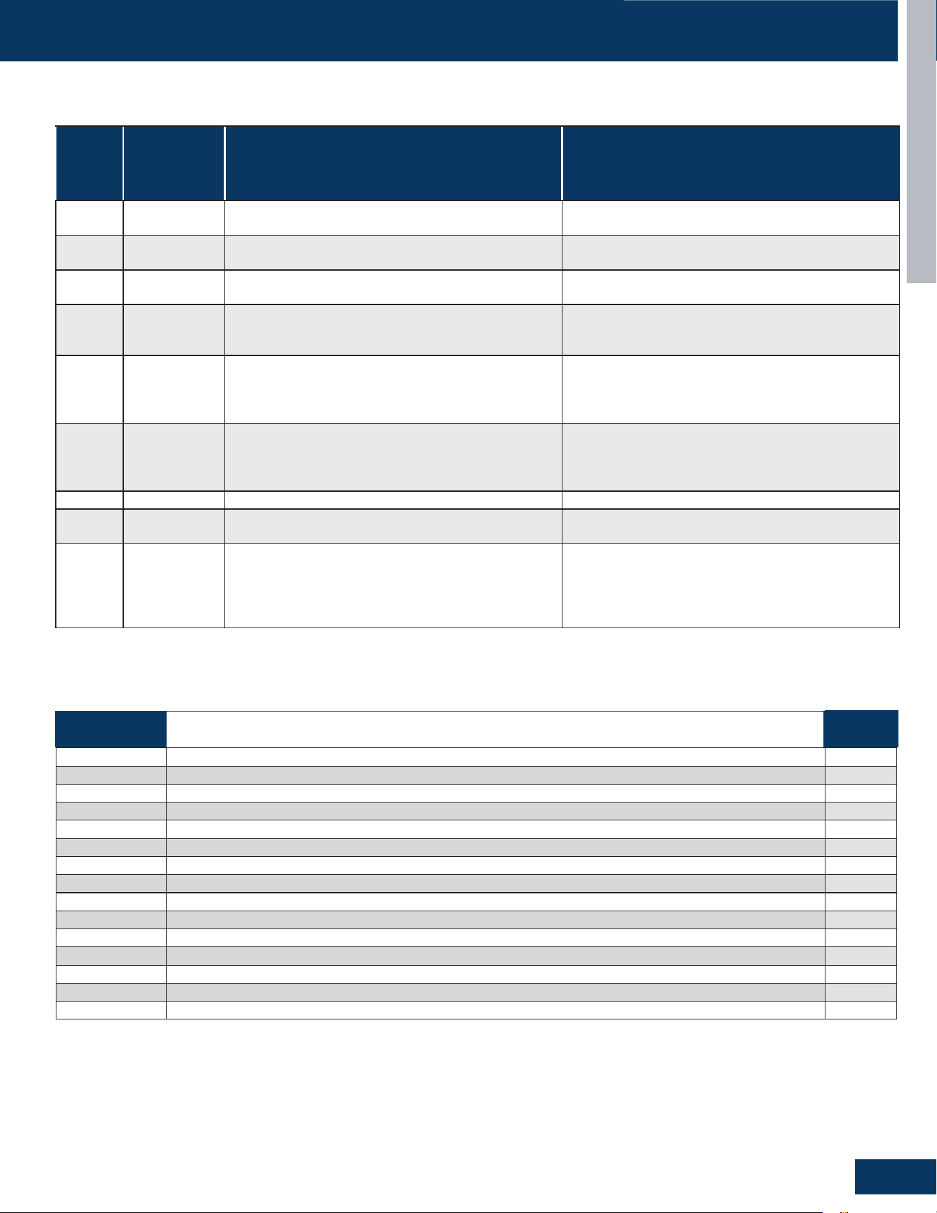
TROUBLESHOOTING AND REFERENCE
G5
ENGLISH
ERROR CODES
PANEL
DISPLAY
WIRED
CONTROLLER
DISPLAY
(YR-E17)
DESCRIPTION POSSIBLE CAUSES
E1 1
INDOOR UNIT AMBIENT TEMPERATURE SENSOR
MALFUNCTION
SENSOR DISCONNECTED,OR BROK EN,OR AT WRONG
POSITION,OR SHORT CIRCUIT
E2 2
INDOOR UNIT PIPING TEMPERATURE SENSOR
MALFUNCTION
SENSOR DISCONNECTED,OR B ,K EN,OR AT WRONG
POSITION OR SHORT CIRCUIT
E4 4 INDOOR PCB EEPROM WRONG
EEPROM CHIP DISCONNECTED OR BROKEN OR
WRONG PROGRAM- MED OR PCB BROKEN
E7 7
ABNORMAL COMMUNI CATION BETWEEN INDOOR
AND OUTDOOR UNITS
WRONG CONNECTION, WIRES DISCONNECTED,
WRONG ADDRESS SETTING OF INDOOR UNIT, FAULTY
POWER SUPPLY, OR FAULTY PCB
EB
07 FLASHING
ON THE
UPPER RIGHT
CORNER
ABNORMAL COMMUNICATION BETWEEN WIRED
CONTROLLER AND INDOOR UNIT
WRONG CONNECTION, WIRED CONTROLLER
BROKEN, OR PCB FAULTY.
E12 OC DRAIN SYSTEM MALFUNCTION
PUMP MOTOR DISCONNECTED OR AT WRONG
POSITION,FLOAT SWITCH DISCONNECTED,
WRONG POSITION, OR SHORT CIRCUIT BRIDGE
DISCONNECTED
E13 OD ZERO CROSS SIGNAL WRONG ZERO CROSS SIGNAL DETECTED WRONG.
E14 OE INDOOR UNIT DC FAN MOTOR ABNORMAL
DC FAN MOTOR DISCONNECTED, FAN BROKEN, OR
CIRCUIT BROKEN
F1-- F45
OUTDOOR
ERROR
CODE+20
CORRESPOND
HEX CODE
OUTDOOR UNIT ERROR
SEE CORRESPOND OUTDOOR UNIT ERROR TROUBLE
SHOOTING. REMARK: F1 MEANS OUTDOOR ERROR
CODE 1, F2 MEANS OUTDOOR ERROR CODE 2, AND
SO ON.
US09FB2BEA / US12FB2BEA / US18FB2BEA
GS09WP2BEA / GS12WP2BEA / GS18WP2BEA / GS24WP2BEA
GS07WB2BEA / GS09WB2BEA / GS12WB2BEA / GS15WB2BEA / GS18WB2BEA / GS24WB2BEA
OUTDOOR
LED
FAULT DESCRIPTION
INDOOR
DISPLAY
/
ROOM TEMPERATURE SENSOR FAILURE E1
/ INDOOR COIL TEMPERATURE SENSOR FAILURE E2
/ INDOOR EEPROM ERROR E4
15 COMMUNICATION FAILURE BETWEEN THE INDOOR & OUTDOOR UNIT E7
/ INDOOR FAN MOTOR FAILURE E14
21 IDU ANTI-FROSTING PROTECTION (COOLING MODE ONLY) /
21 INDOOR UNIT OVER TEMPERATURE (HEATING MODE ONLY) /
28 LACK OF REFRIGERANT OR DISCHARGING /
/ REFRIGERANT LEAKAGE FAULT >10% LFL AA
/ REFRIGERANT LEAKAGE FAULT <8% LFL Ab
/ LEAK SENSOR COMMUNICATION FAULT Ac
/ LEAKAGE SENSOR SELF-CHECK FAULT SELF-CHECK FAULT Ad
/ SENSOR REACHING END OF LIFE WARNING AE
/ LEAKAGE SENSOR END OF LIFE AF
/ DIP SWITCH ENABLED. NO SENSOR DETECTED bA
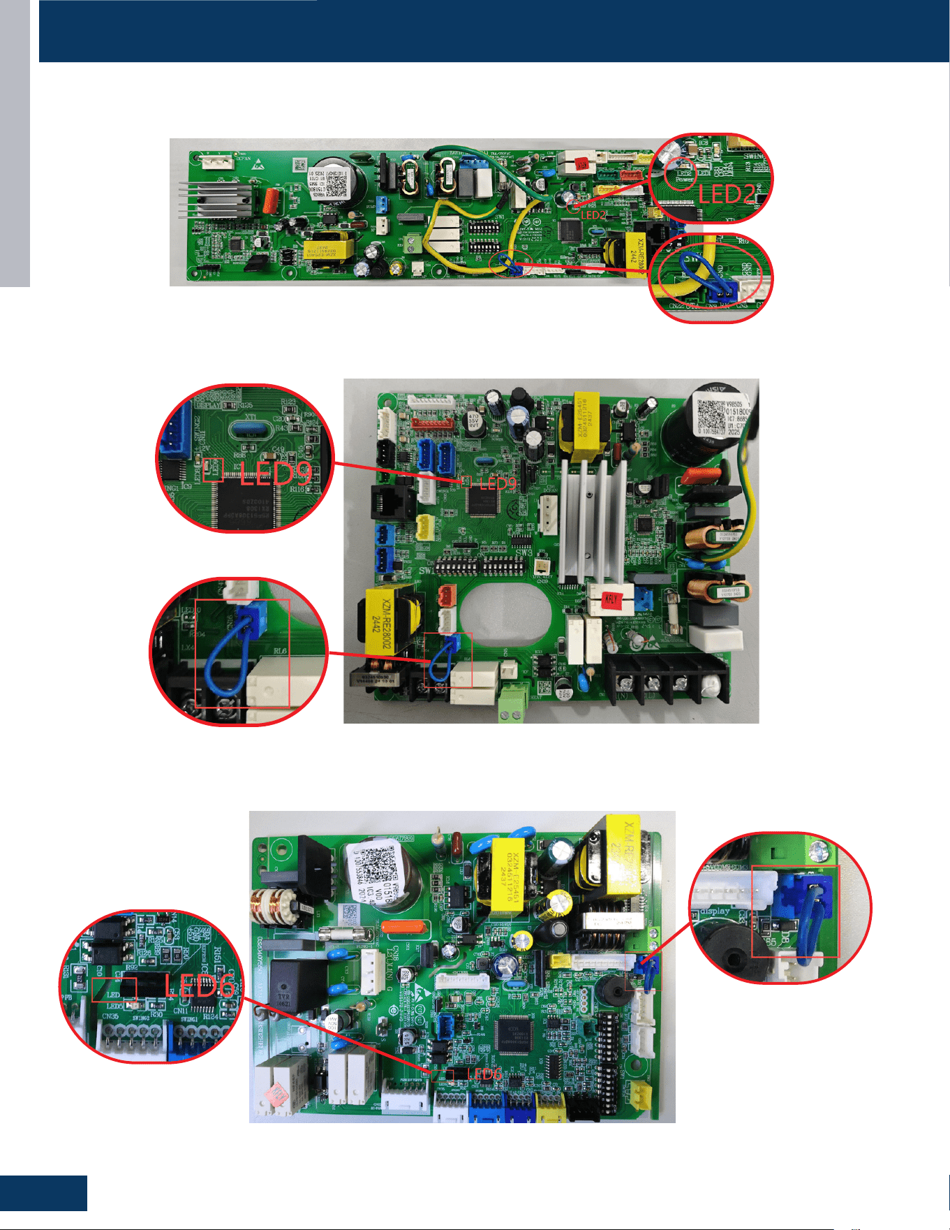
TROUBLESHOOTING AND REFERENCE
G6
ENGLISH
ERROR CODES
Error Code LED and Jump Wire Identication
US09CB2BEA / US12CB2BEA / US18CB2BEA / US24LB2BEA / US30LB2BEA / US36LB2BEA
US09MB2BEA / US12MB2BEA / US18MB2BEA / US24MB2BEA / US30MB2BEA / US36MB2BEA
US09FB2BEA / US12FB2BEA / US18FB2BEA
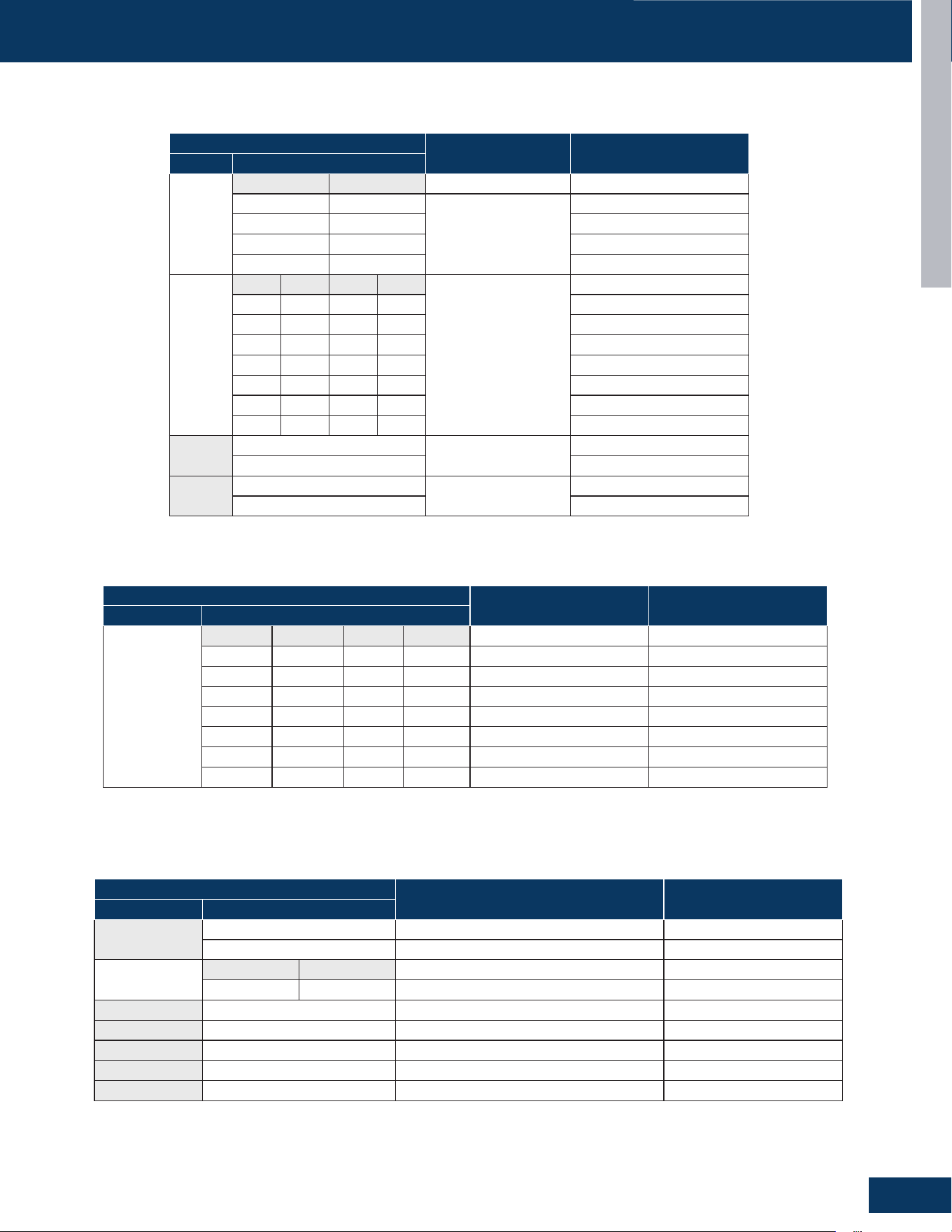
TROUBLESHOOTING AND REFERENCE
G7
ENGLISH
OUTDOOR UNIT DIP SWITCH SETTINGS
PCB 0151801029
2G18AD2BEA / 3G24AD2BEA
DIP SWITCHES
SETTING ITEM DESCRIPTION
NO. SETTING
SW5-1
SW5-2
SW5-1 SW5-2
OFF OFF
Outdoor Mode Setting
HeatPumpα=8(Default)
OFF ON HeatPumpα=6
ON OFF Cooling Only
ON ON HeatPumpOnlyα=6
SW5-3
SW5-4
SW5-5
SW5-6
SW5-3 SW5-4 SW5-5 SW5-6
Outdoor Air
Conditioning Option
OFF OFF OFF OFF 2G18AD2BEA
OFF OFF OFF ON 3G24AD2BEA
OFF ON ON OFF
OFF ON ON ON
ON OFF OFF OFF
ON OFF OFF ON
ON OFF ON ON
SW5-7
OFF
ModiedTemperature
DierenceFactor
Default
ON
SW5-8
OFF
Silent Operation
Default
ON
DIP SWITCHES
SETTING ITEM DESCRIPTION
NO. SETTING
SW6-1
SW6-2
SW6-3
SW6-4
SW6-1 SW6-2 SW6-3 SW6-4 Outdoor Address Indoor Address
OFF OFF OFF OFF 0# 1-5
ON OFF OFF OFF 1# 6-10
OFF ON OFF OFF 2# 11-15
ON ON OFF OFF 3# 16-20
··· ··· ··· ··· ··· ···
ON ON ON ON 15# 76-80
Note: this is for addressing individual units when connected to a multi-unit centralized controller
DIP SWITCHES
SETTING ITEM DESCRIPTION
NO. SETTING
SW7-1
OFF First-In First Out Default
ON Outdoor Ambient Temperature Priority
SW7-2
SW7-3
SW7-2 SW7-3
ON OFF American Model Default
SW7-4 OFF Default
SW7-5 OFF Default
SW7-6 OFF Default
SW7-7 OFF Default
SW7-8 OFF Default
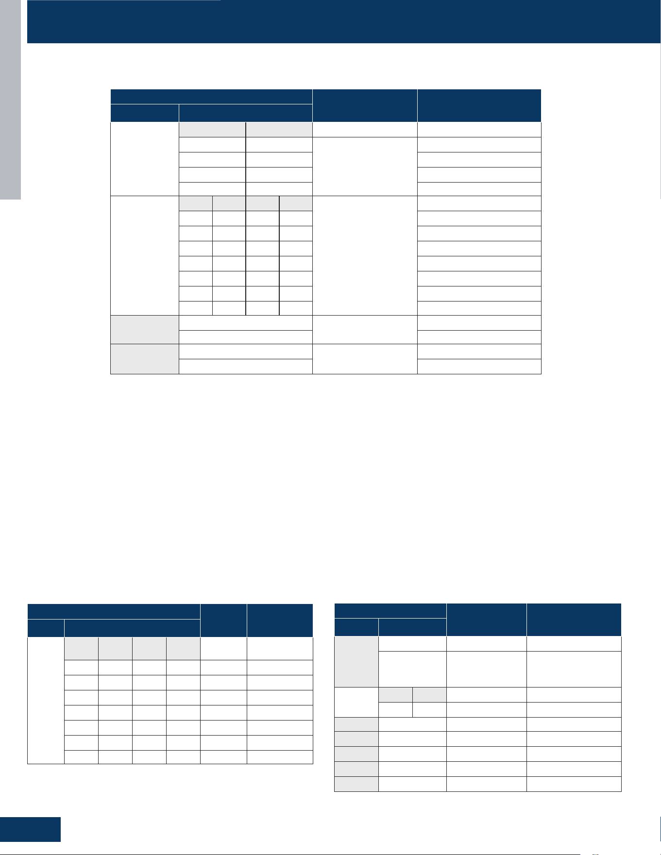
TROUBLESHOOTING AND REFERENCE
G8
ENGLISH
OUTDOOR UNIT DIP SWITCH SETTINGS
PCB 0151801029B
2G20ED2BEA / 3G24ED2BEA / 4G36AD2BEA
DIP SWITCHES
SETTING ITEM DESCRIPTION
NO. SETTING
SW5-1
SW5-2
SW5-1 SW5-2
OFF OFF
Outdoor Mode Setting
HeatPumpα=8(Default)
OFF ON HeatPumpα=6
ON OFF Cooling Only
ON ON
HeatPumpOnlyα=6
SW5-3
SW5-4
SW5-5
SW5-6
SW5-3 SW5-4 SW5-5 SW5-6
Outdoor Air
Conditioning Option
OFF OFF OFF OFF
OFF OFF OFF ON
OFF ON ON OFF 2G20ED2BEA
OFF ON ON ON 3G24ED2BEA
ON OFF OFF OFF 4G36AD2BEA
ON OFF OFF ON
ON OFF ON ON
SW5-7
OFF
ModiedTemperature
DierenceFactor
Default
ON
SW5-8
OFF
Silent Operation
Default
ON
SW5-7:
Modiedtemperaturedierencefactor
Modiedtemperaturedierencefactorreferstothecorrectionofthetargetcoiltemperaturebasedonthedierencebetweentheindoor
ambient temperature and the set temperature
ON – The target temperature will be adjusted based upon the set temperature to ambient temperature
OFF – No adjustment will be made to the target coil temperature
SW5-8: Silent operation
If the unit is running, the fan speed and frequency shall be implemented in accordance with the following conditions; if the unit is not started at
this time, the following conditions shall be implemented after the unit is started:
IF SILENT MODE On (SW5-8 ON): The maximum fan speed of the Outdoor fan motor is level 5; if the current speed is less than or equal to level
5, it shall operate at the current speed; if it is higher than level 5, it shall operate at level 5.
The maximum allowable operating frequency of the compressor is reduced by 15HZ (E); if the current frequency is less than or equal to
“maximum frequency - 15HZ”, it shall operate at the current frequency. If it is higher than “maximum frequency - 15HZ”, it shall operate at
“maximum frequency - 15HZ”. The maximum frequency refers to the maximum value among all ambient temperature division intervals. Other
frequency limiting conditions remain valid.
DIP SWITCHES
SETTING ITEM DESCRIPTION
NO. SETTING
SW7-1
OFF First-In First Out Default
ON
Outdoor Ambient
Temperature
Priority
SW7-2
SW7-3
SW7-2 SW7-3
ON OFF American Model Default
SW7-4 OFF Default
SW7-5 OFF Default
SW7-6 OFF Default
SW7-7 OFF Default
SW7-8 OFF Default
DIP SWITCHES
SETTING
ITEM
DESCRIPTION
NO. SETTING
SW6-1
SW6-2
SW6-3
SW6-4
SW6-1 SW6-2 SW6-3 SW6-4
Outdoor
Address
Indoor
Address
OFF OFF OFF OFF 0# 1-5
ON OFF OFF OFF 1# 6-10
OFF ON OFF OFF 2# 11-15
ON ON OFF OFF 3# 16-20
··· ··· ··· ··· ··· ···
ON ON ON ON 15# 76-80
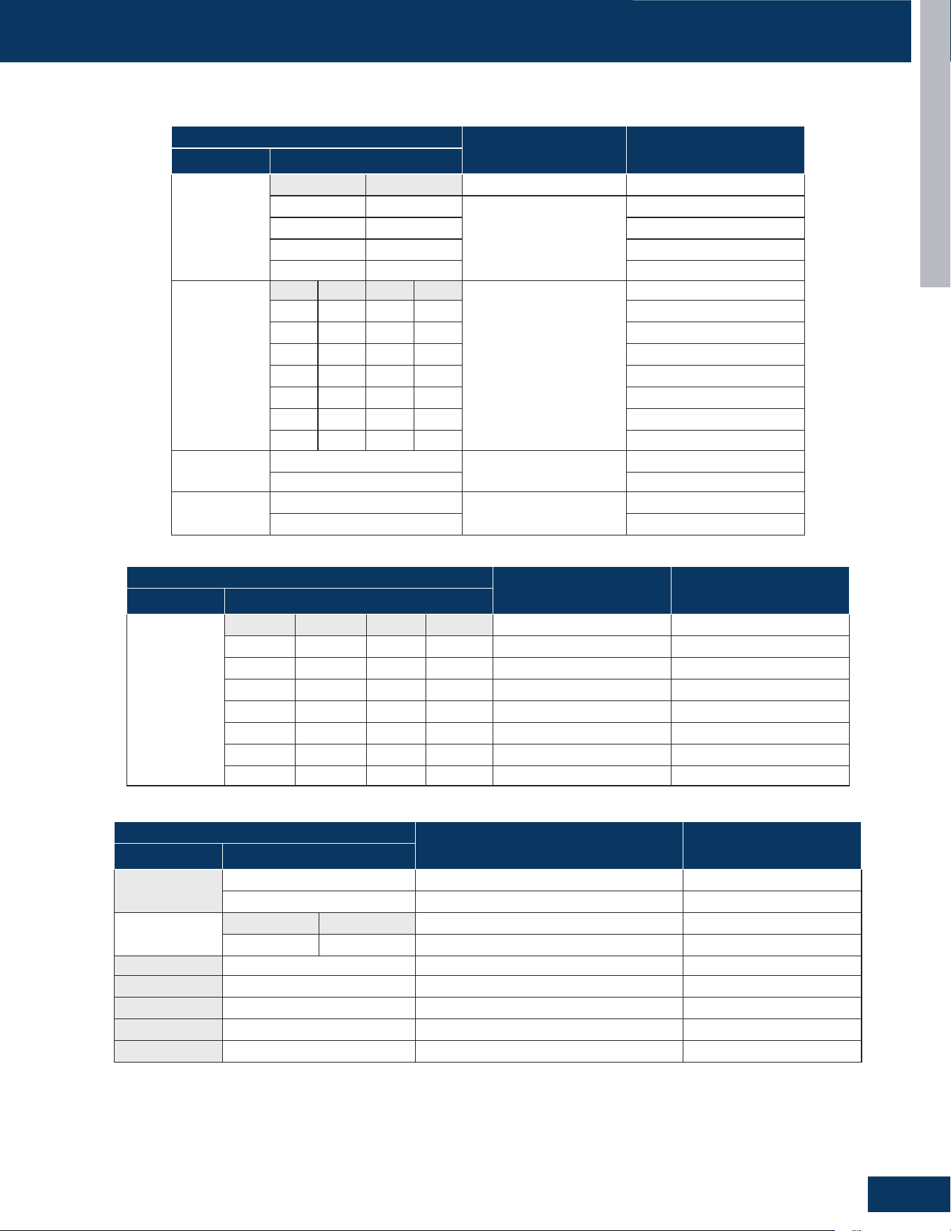
TROUBLESHOOTING AND REFERENCE
G9
ENGLISH
OUTDOOR UNIT DIP SWITCH SETTINGS
DIP SWITCHES
SETTING ITEM DESCRIPTION
NO. SETTING
SW6-1
SW6-2
SW6-3
SW6-4
SW6-1 SW6-2 SW6-3 SW6-4 Outdoor address Indoor address
OFF OFF OFF OFF 0# 1-5
ON OFF OFF OFF 1# 6-10
OFF ON OFF OFF 2# 11-15
ON ON OFF OFF 3# 16-20
··· ··· ··· ··· ··· ···
ON ON ON ON 15# 76-80
DIP SWITCHES
SETTING ITEM DESCRIPTION
NO. SETTING
SW7-1
OFF
First-inrstout Default
ON Outdoor ambient temperature priority
SW7-2
SW7-3
SW7-2 SW7-3
ON OFF American model Default
SW7-4 OFF Default
SW7-5 OFF Default
SW7-6 OFF Default
SW7-7 OFF Default
SW7-8 OFF Default
PCB 0151801003 0150406834H
4G36ED2BEA / 5G42ED2BEA
DIP SWITCHES
SETTING ITEM DESCRIPTION
NO. SETTING
SW5-1
SW5-2
SW5-1 SW5-2
OFF OFF
Outdoor Mode Setting
HeatPumpα=8(Default)
OFF ON HeatPumpα=6
ON OFF Cooling Only
ON ON
HeatPumpOnlyα=6
SW5-3
SW5-4
SW5-5
SW5-6
SW5-3 SW5-4 SW5-5 SW5-6
Outdoor Air conditioning
option
OFF OFF OFF OFF
OFF OFF OFF ON
OFF ON ON OFF
OFF ON ON ON
ON OFF OFF OFF
ON OFF OFF ON 4G36ED2BEA
ON OFF ON ON 5G42ED2BEA
SW5-7
OFF
Modiedtemperature
dierencefactor
Default
ON
SW5-8
OFF
Silent operation
Default
ON
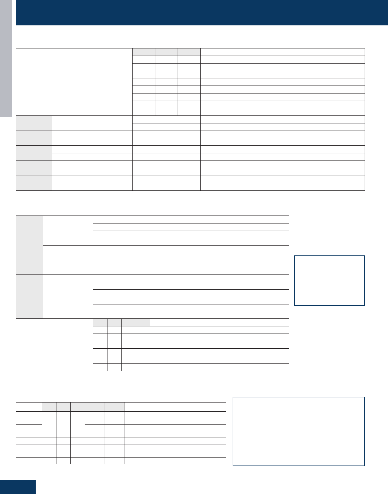
TROUBLESHOOTING AND REFERENCE
G10
ENGLISH
INDOOR UNIT DIP SWITCH SETTINGS
SW1-1
SW1-2
SW1-3
HP
SW1-1 SW1-2 SW1-3 HP
0 0 0 09K
1 0 0 12K
0 1 0 18K
1 1 0 24K
0 0 1 30K
1 0 1 36K
0 1 1 42K
1 1 1 48K
SW1_4 Room Card
0 Room Card Invalid
1 Room Card Valid
SW1_5 Refrigerant Detector
0 Refrigerant Detector is Functional
1 The Refrigerant Detector Function is Invalid
SW1_6
Fresh Air 0 Fresh Air
Fault Alarm 1 Fault Alarm
SW1_7 Filter/Refrigeration Fan Stops
0 None-Filter Alarm Reminder+Refrigeration Fan Stops
1 Filter Reminder+Refrigeration Fan Does Not Stop
SW1_8 US/Non-US Models
0 US Models
1 Non US Models
BM1
In the following table, 1 represents ON and 0 represents OFF.
SW3_1 Special Fresh Air
[1] Special Fresh Air Selection for Duct Unit
0 Valid
1 Invalid
SW3_2
Model [2] Model
Swing Wind
Selection
0
Cassette Single Swing Wind - Synchronized Swing of
Swing Blades
1
Cassette Unit Four Swing Wind - Four Swing Blades
SwingatDierentAngles,MisalignedSwing
SW3_3* Electrical Heating
[3] Electromechanical Heating Selection of Air Duct
0 Invalid
1 Valid
SW3_4 Model
0 Ultra-Slim Ducted Unit with 4-Level Static Pressure
1
Medium Static Pressure Duct with 10-Level Static
Pressure Adjustment
SW3_5
SW3_6
SW3_7
SW3_8
Wired Controller
Indoor Unit Group
[5] [6] [7] [8] Wired Controller Indoor Unit Address (Group Address)
0 0 0 0 0 # (Wired Control Host) (Default)
0 0 0 1 1#(Line-Controlled Slave Machine)
0 0 1 0 2#(Line-Controlled Slave Machine)
0 0 1 1 3#(Line-Controlled Slave Machine)
… … … … ……
1 1 1 1 15#(Line-Controlled Slave Machine)
BM3
In the following table, 1 represents ON and 0 represents OFF.
SW3_1 The fan selection
function in cooling mode
is only applicable to duct
and slim duct.
SW3_4 Only applicable to
slim duct
Number RJ1 RJ2 RJ3 SW3-2 SW3-3 Model
1
0 0 0
0 0
Crane
2 0 1 Cassette with 1 Oscillating Wind
3 1 0 Cassette with Four-Way Oscillating Wind
4 1 1 Cassette with Light Panel
5 0 0 1 0 0 Console
6 0 1 0 0 0 Small Duct
7 0 1 0 0 1 High-Capacity Duct
8 - - - - - Reserve
Identication of duct, cassette, and console based on hardware jumpers.
Model Identication Code Comparison Table.
• Suitable for convertible, 2HP cassette (matched
with single swing wind), 2HP cassette (matched
with four swing wind), 3HP cassette (equipped
with display board)
• For example, if the convertible has 0 0 0 0, the
resistance should be welded RJ1/RJ2/RJ3.
• Simultaneously dial the second digit of code BM3
to OFF and the third digit to OFF.
• The same setup method is used for other models.
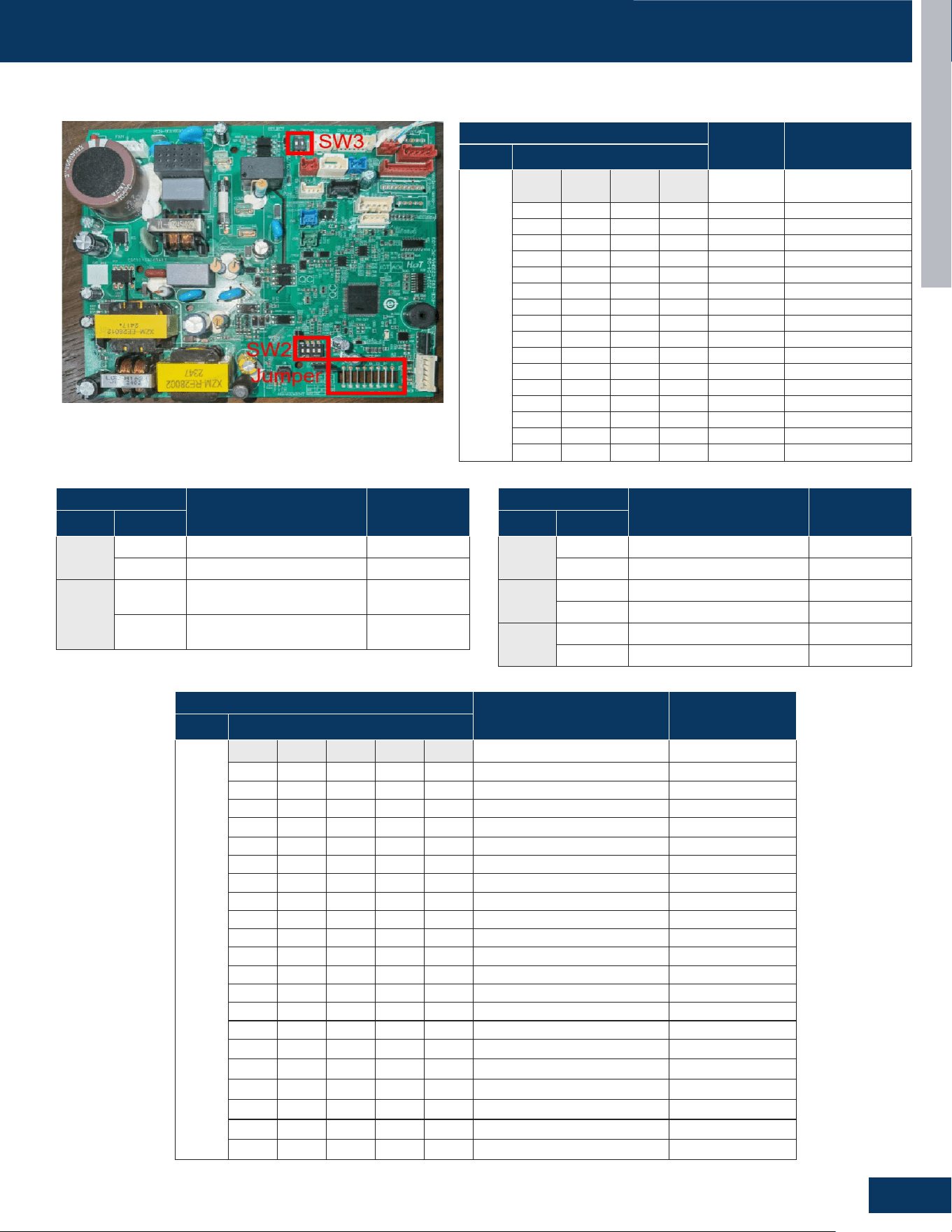
TROUBLESHOOTING AND REFERENCE
G11
ENGLISH
INDOOR UNIT DIP SWITCH SETTINGS
INTRODUCTION
PAGE 4
ENGLISH
Dip Switch Setting
QS09WP2BEA、QS12WP2BEA、QS18WP2BEA、QS24WP2BEA
wire controller address
GS09WP2BEA / GS12WP2BEA / GS18WP2BEA / GS24WP2BEA
DIP SWITCHES
SETTING
ITEM
DESCRIPTION
NO. SETTING
SW2-1
SW2-2
SW2-3
SW2-4
SW2-1 SW2-2 SW2-3 SW2-4
Controller
Address
Default
OFF OFF OFF OFF 0#
OFF OFF OFF ON 1#
OFF OFF ON OFF 2#
OFF OFF ON ON 3#
OFF ON OFF OFF 4#
OFF ON OFF ON 5#
OFF ON ON OFF 6#
OFF ON ON ON 7#
ON OFF OFF OFF 8#
ON OFF OFF ON 9#
ON OFF ON OFF 10#
ON OFF ON ON 11#
ON ON OFF OFF 12#
ON ON OFF ON 13#
ON ON ON OFF 14#
ON ON ON ON 15#
DIP SWITCHES
SETTING ITEM DESCRIPTION
NO. SETTING
J7-J-3
J7 J6 J5 J4 J3 Controller Address
OFF OFF OFF OFF OFF Arctic 09K
OFF OFF OFF OFF ON Arctic 12K
OFF OFF OFF ON OFF Arctic 18K
OFF OFF OFF ON ON Arctic 24K
OFF OFF ON OFF OFF Reserved
OFF OFF ON OFF ON Reserved
OFF OFF ON ON OFF FlexFit 06K
OFF OFF ON ON ON FlexFit 09K/ Tempo 9K
OFF ON OFF OFF OFF FlexFit 12K/ Tempo 12K
OFF ON OFF OFF ON FlexFit 15K
OFF ON OFF ON OFF FlexFit 18K/ Tempo 18K
OFF ON OFF ON ON FlexFit 24K/ Tempo 24K
OFF ON ON OFF OFF FlexFit 30K
OFF ON ON OFF ON FlexFit 36K
OFF ON ON ON OFF Reserved
OFF ON ON ON ON Reserved
ON OFF OFF OFF OFF Reserved
ON OFF OFF OFF ON Reserved
ON OFF OFF ON OFF Reserved
-- -- -- -- -- Reserved
ON ON
ON ON ON Reserved
DIP SWITCHES
SETTING ITEM DESCRIPTION
NO. SETTING
SW3-1
OFF Central Controller Default
ON 24V Controller
SW3-2
OFF
Refrigerant Leakage Sensor
Disable
ON
Refrigerant Leakage Sensor
Enable
Default
DIP SWITCHES
SETTING ITEM DESCRIPTION
NO. SETTING
J1
OFF Room card valid
ON Room card invalid Default
J2
OFF Slave
ON Master Default
J8
OFF WiFi 2. 18 protocol
ON WiFi GE3 protocol Default
GS07WB2BEA / GS09WB2BEA / GS12WB2BEA / GS15WB2BEA / GS18WB2BEA / GS24WB2BEA
TROUBLESHOOTING AND REFERENCE
G12
ENGLISH
SENSOR RESISTANCE TABLES
MODEL
TEMPERATURE SENSOR
RESISTANCE VALUE
1Q24RT2BEA
TEB25/50=3700K±3%,R25=10KΩ±3%
TDB25/80=4450K±3%,R80=50KΩ±3%
TAB25/50=3700K±3%,R25=10KΩ±3%
TSB25/50=3700K±3%,R25=10KΩ±3%
TCB25/50=3700K±3%,R25=10KΩ±3%"
1Q3036RT2BEA
TEB25/50=3700K±3%,R25=10KΩ±3%
TDB25/80=4450K±3%,R80=50KΩ±3%
TAB25/50=3700K±3%,R25=10KΩ±3%
TSB25/50=3700K±3%,R25=10KΩ±3%
TCB25/50=3700K±3%,R25=10KΩ±3%"
MODEL FUNCTION PART CODE CHARACTERISTICS
2G18AD2BEA
Outdoor Ambient Temperature Sensor 0150403772C
TEB25/50=3700K±3%R25=10KΩ±3%
TDB25/80=4450K±3%R80=50KΩ±3%
TAB25/50=3700K±3%R25=10KΩ±3%
TSB25/50=3700K±3%R25=10KΩ±3%
TCB25/50=3700K±3%R25=10KΩ±3%
Gas Pipe Temperature Sensor 0150402454B
B25/50=3700K±3%
R25=10KΩ±3%
Liquid Pipe Temperature Sensor 0150402454A
B25/50=3700K±3%
R25=10KΩ±3%
3G24AD2BEA
Outdoor Ambient Temperature Sensor 0150403772C
TEB25/50=3700K±3%R25=10KΩ±3%
TDB25/80=4450K±3%R80=50KΩ±3%
TAB25/50=3700K±3%R25=10KΩ±3%
TSB25/50=3700K±3%R25=10KΩ±3%
TCB25/50=3700K±3%R25=10KΩ±3%
Gas Pipe Temperature Sensor 0150405725
B25/50=3700K±3%
R25=10KΩ±3%
Liquid Pipe Temperature Sensor 0150405726
B25/50=3700K±3%
R25=10KΩ±3%
2G20ED2BEA
Outdoor Ambient Temperature Sensor 0150403772C
TEB25/50=3700K±3%R25=10KΩ±3%
TDB25/80=4450K±3%R80=50KΩ±3%
TAB25/50=3700K±3%R25=10KΩ±3%
TSB25/50=3700K±3%R25=10KΩ±3%
TCB25/50=3700K±3%R25=10KΩ±3%
Gas Pipe Temperature Sensor 0150405722
B25/50=3700K±3%
R25=10KΩ±3%
Liquid Pipe Temperature Sensor 0150405724
B25/50=3700K±3%
R25=10KΩ±3%
3G24ED2BEA
Outdoor Ambient Temperature Sensor 0150403772C
TEB25/50=3700K±3%R25=10KΩ±3%
TDB25/80=4450K±3%R80=50KΩ±3%
TAB25/50=3700K±3%R25=10KΩ±3%
TSB25/50=3700K±3%R25=10KΩ±3%
TCB25/50=3700K±3%R25=10KΩ±3%
Gas Pipe Temperature Sensor 0150405725
B25/50=3700K±3%
R25=10KΩ±3%
Liquid Pipe Temperature Sensor 0150405726
B25/50=3700K±3%
R25=10KΩ±3%
TROUBLESHOOTING AND REFERENCE
G13
ENGLISH
SENSOR RESISTANCE TABLES
MODEL
AMBIENT TEMPERATURE SENSOR PIPE TEMPERATURE SENSOR
RESISTANCE VALUE RESISTANCE VALUE
US18CB2BEA
"R25=10KΩ±3%
B25/50=3700K±3%"
"R25=10KΩ±3%
B25/50=3700K±3%"
US24LB2BEA
US30LB2BEA
US36LB2BEA
US09MB2BEA
"R25=10KΩ±3%
B25/50=3700K±3%"
"R25=10KΩ±3%
B25/50=3700K±3%"
US12MB2BEA
US18MB2BEA
US24MB2BEA
US30MB2BEA
US36MB2BEA
US09FB2BEA
"R25=10KΩ±3%
B25/50=3700K±3%"
"R25=23KΩ±3%
B25/50=4200K±3%"
US12FB2BEA
US18FB2BEA
MODEL FUNCTION PART CODE CHARACTERISTICS
4G36AD2BEA
Outdoor Ambient Temperature Sensor 0150403772C
TEB25/50=3700K±3%R25=10KΩ±3%
TDB25/80=4450K±3%R80=50KΩ±3%
TAB25/50=3700K±3%R25=10KΩ±3%
TSB25/50=3700K±3%R25=10KΩ±3%
TCB25/50=3700K±3%R25=10KΩ±3%
Gas Pipe Temperature Sensor 0150403772A
B25/50=3700K±3%
R25=10KΩ±3%
Liquid Pipe Temperature Sensor 0150403772B
B25/50=3700K±3%
R25=10KΩ±3%
4G36ED2BEA
Outdoor Ambient Temperature Sensor 0150403772C
TEB25/50=3700K±3%R25=10KΩ±3%
TDB25/80=4450K±3%R80=50KΩ±3%
TAB25/50=3700K±3%R25=10KΩ±3%
TSB25/50=3700K±3%R25=10KΩ±3%
TCB25/50=3700K±3%R25=10KΩ±3%
Gas Pipe Temperature Sensor 0150403772A
B25/50=3700K±3%
R25=10KΩ±3%
Liquid Pipe Temperature Sensor 0150403772B
B25/50=3700K±3%
R25=10KΩ±3%
5G42ED2BEA
Outdoor Ambient Temperature Sensor 0150403772D
TEB25/50=3700K±3%R25=10KΩ±3%
TDB25/80=4450K±3%R80=50KΩ±3%
TAB25/50=3700K±3%R25=10KΩ±3%
TSB25/50=3700K±3%R25=10KΩ±3%
TCB25/50=3700K±3%R25=10KΩ±3%
Gas Pipe Temperature Sensor 0150403772D
B25/50=3700K±3%
R25=10KΩ±3%
Liquid Pipe Temperature Sensor 0150403772D
B25/50=3700K±3%
R25=10KΩ±3%
TROUBLESHOOTING AND REFERENCE
G14
ENGLISH
SENSOR RESISTANCE TABLES
B25/50=3700K±3%R25=10KΩ±3%
Temp Resistance(KΩ) Temp Resistance(KΩ)
(°C) Rmax R (t) Normal Rmin (°C) Rmax R (t) Normal Rmin
-40 246.890 229.239 211.587 11 18.864 18.135 17.406
-39 233.754 217.183 200.612 12 18.039 17.354 16.669
-38 221.368 205.809 190.250 13 17.254 16.611 15.968
-37 209.686 195.075 180.464 14 16.507 15.903 15.299
-36 198.665 184.942 171.219 15 15.797 15.229 14.661
-35 188.265 175.375 162.485 16 15.120 14.587 14.054
-34 178.449 166.339 154.230 17 14.476 13.975 13.474
-33 169.181 157.803 146.426 18 13.862 13.392 12.922
-32 160.429 149.738 139.046 19 13.277 12.836 12.395
-31 152.162 142.114 132.067 20 12.720 12.306 11.892
-30 144.350 134.907 125.464 21 12.189 11.801 11.413
-29 136.519 127.675 118.831 22 11.683 11.319 10.955
-28 129.381 121.081 112.781 23 11.200 10.858 10.516
-27 122.638 114.849 107.060 24 10.739 10.419 10.099
-26 116.268 108.958 101.648 25 10.300 10.000 9.700
-25 110.249
103.388 96.527 26 9.894 9.600 9.306
-24 104.563 98.123 91.683 27 9.505 9.217 8.929
-23 99.190 93.144 87.098 28 9.134 8.852 8.570
-22 94.111 88.435 82.759 29 8.779 8.503 8.227
-21 89.311 83.982 78.653 30 8.441 8.170 7.899
-20 84.518 79.529 74.540 31 8.116 7.851 7.586
-19 80.484 75.785 71.086 32 7.805 7.546 7.287
-18 76.428 72.015 67.602 33 7.509 7.255 7.001
-17 72.591 68.447 64.303 34 7.225 6.976 6.727
-16 68.963 65.071 61.179 35 6.953 6.710 6.467
-15 65.530 61.874 58.218 36 6.692 6.454 6.216
-14 62.283 58.848 55.413 37 6.443 6.210 5.977
-13 59.210 55.983 52.756 38 6.204 5.976 5.748
-12 56.300 53.269 50.238 39 5.976 5.753 5.530
-11 53.547 50.699 47.851 40 5.756 5.538 5.320
-10 50.940 48.264 45.588 41 5.546 5.333 5.120
-9 48.472 45.957 43.442 42 5.345 5.136 4.927
-8 46.134 43.770 41.406 43 5.151 4.947 4.743
-7 43.918 41.697 39.476 44 4.967 4.767 4.567
-6 41.819 39.731 37.643 45 4.788 4.593 4.398
-5 39.830 37.868 35.906 46 4.618 4.427 4.236
-4 37.944 36.100 34.256 47 4.455 4.268 4.081
-3 36.157 34.423 32.689 48 4.298 4.115 3.932
-2 34.462 32.832 31.202 49 4.147 3.968 3.789
-1 32.854 31.322 29.790 50 4.004 3.829 3.654
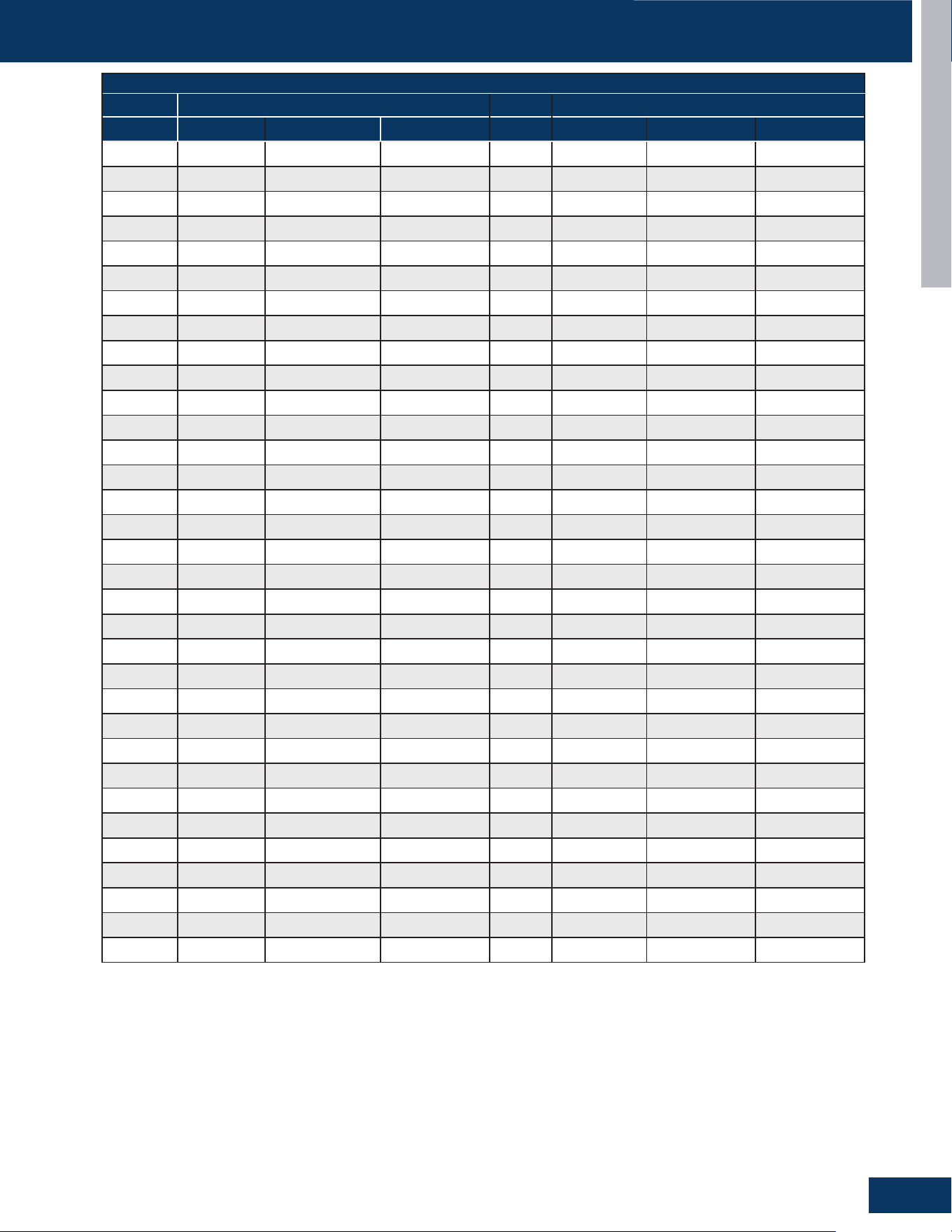
TROUBLESHOOTING AND REFERENCE
G15
ENGLISH
SENSOR RESISTANCE TABLES
B25/50=3700K±3%R25=10KΩ±3%
Temp Resistance(KΩ) Temp Resistance(KΩ)
(°C) Rmax R (t) Normal Rmin (°C) Rmax R (t) Normal Rmin
0 31.362 29.920 28.478 51 3.863 3.692 3.521
1 29.881 28.527 27.173 52 3.729 3.562 3.395
2 28.507 27.234 25.961 53 3.601 3.438 3.275
3 27.202 26.006 24.810 54 3.478 3.318 3.158
4 25.965 24.840 23.715 55 3.359 3.203 3.047
5 24.788 23.731 22.674 56 3.246 3.093 2.940
6 23.672 22.678 21.684 57 3.136 2.987 2.838
7 22.610 21.676 20.742 58 3.031 2.885 2.739
8 21.601 20.723 19.845 59 2.930 2.787 2.644
9 20.642 19.817 18.992 60 2.833 2.693 2.553
10 19.730 18.955 18.180 61 2.739 2.602 2.465
62 2.649 2.515 2.381 84 1.321 1.238 1.155
63 2.562 2.431 2.300 85 1.281 1.200 1.119
64 2.478 2.350 2.222 86 1.244 1.165 1.086
65 2.398 2.273 2.148 87 1.209 1.131 1.053
66 2.320
2.198 2.076 88 1.173 1.097 1.021
67 2.246 2.126 2.006 89 1.140 1.065 0.990
68 2.174 2.057 1.940 90 1.107 1.034 0.961
69 2.104 1.990 1.876 91 1.076 1.004 0.932
70 2.038 1.926 1.814 92 1.045 0.975 0.905
71 1.974 1.864 1.754 93 1.016 0.947 0.878
72 1.912 1.805 1.698 94 0.987 0.920 0.853
73 1.853 1.748 1.643 95 0.960 0.894 0.828
74 1.795 1.692 1.589 96 0.934 0.869 0.804
75 1.739 1.639 1.539 97 0.907 0.844 0.781
76 1.686 1.588 1.490 98 0.883 0.821 0.759
77 1.634 1.538 1.442 99 0.859 0.798 0.737
78 1.585 1.491 1.397 100 0.836 0.776 0.716
79 1.537 1.445 1.353 101 0.814 0.755 0.696
80 1.490 1.400 1.310 102 0.791 0.734 0.677
81 1.445 1.357 1.269 103 0.771 0.715 0.659
82 1.402 1.316 1.230 104 0.750 0.695 0.640
83 1.361 1.276 1.191 105 0.731 0.677 0.623
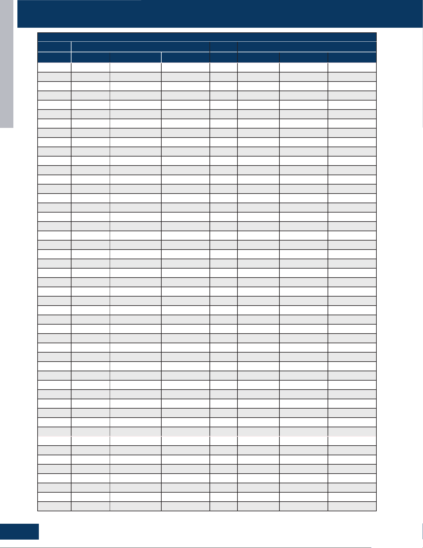
TROUBLESHOOTING AND REFERENCE
G16
ENGLISH
SENSOR RESISTANCE TABLES
B25/80=4450K±3%R80=50KΩ±3%
Temp Resistance(KΩ) Temp Resistance(KΩ)
(°C) Rmax R (t) Normal Rmin (°C) Rmax R (t) Normal Rmin
-40 23982.342 21280.977 18579.613 11 1126.419 1041.293 956.167
-39 22397.462 19890.917 17384.372 12 1067.463 987.477 907.491
-38 20925.744 18599.155 16272.567 13 1011.977 936.799 861.621
-37 19558.506 17398.211 15237.916 14 959.732 889.052 818.372
-36 18287.777 16281.212 14274.647 15 910.510 844.042 777.574
-35 17106.237 15241.843 13377.450 16 864.114 801.590 739.066
-34 16007.159 14274.298 12541.437 17 820.361 761.533 702.705
-33 14984.359 13373.234 11762.109 18 779.081 723.717 668.353
-32 14032.148 12533.735 11035.322 19 740.117 688.001 635.885
-31 13145.291 11751.273 10357.255 20 703.323 654.254 605.185
-30 12318.968 11021.678 9724.388 21 668.565 622.355 576.145
-29 11551.311 10343.407 9135.504 22 635.715 592.189 548.663
-28 10835.229 9710.234 8585.239 23 604.657 563.651 522.645
-27 10167.003 9118.935 8070.867 24 575.282 536.644 498.006
-26 9543.200 8566.532 7589.865 25 547.490 511.076 474.662
-25 8960.652
8050.276 7139.901 26 521.186 486.862 452.538
-24 8416.430 7567.624 6718.818 27 496.281 463.922 431.563
-23 7907.828 7116.224 6324.620 28 472.693 442.182 411.671
-22 7432.345 6693.901 5955.457 29 450.344 421.572 392.800
-21 6987.666 6298.642 5609.618 30 429.165 402.028 374.891
-20 6571.650 5928.583 5285.516 31 409.087 383.489 357.891
-19 6187.164 5586.374 4985.585 32 390.047 365.898 341.749
-18 5826.712 5265.313 4703.915 33 371.986 349.201 326.416
-17 5488.692 4964.004 4439.315 34 354.850 333.349 311.848
-16 5171.616 4681.148 4190.680 35 338.586 318.295 298.004
-15 4874.100 4415.539 3956.978 36 323.147 303.995 284.843
-14 4594.858 4166.054 3737.249 37 308.485 290.407 272.329
-13 4332.694 3931.647 3530.600 38 294.559 277.493 260.427
-12 4086.494 3711.346 3336.198 39 281.328 265.216 249.104
-11 3855.222 3504.244 3153.266 40 268.753 253.541 238.329
-10 3637.915 3309.498 2981.082 41 256.801 242.437 228.073
-9 3433.673 3126.321 2818.969 42 245.438 231.873 218.308
-8 3241.661 2953.980 2666.299 43 234.630 221.820 209.010
-7 3061.098 2791.790 2522.482 44 224.350 212.252 200.154
-6 2891.257 2639.114 2386.971 45 214.569 203.142 191.715
-5 2731.460 2495.357 2259.253 46 205.260 194.467 183.674
-4 2581.076 2359.962 2138.848 47 196.399 186.204 176.009
-3 2439.514 2232.412 2025.310 48 187.963 178.333 168.703
-2 2306.222 2112.221 1918.220 49 179.929 170.832 161.735
-1 2180.688 1998.938 1817.187 50 172.275 163.682 155.089
0 2094.972 1921.993 1749.014 51 164.984 156.866 148.748
1 1975.099 1813.265 1651.431 52 158.036 150.367 142.698
2 1863.127 1711.646 1560.165 53 151.412 144.168 136.924
3 1758.449 1616.593 1474.737 54 145.099 138.255 131.411
4 1660.513 1527.611 1394.709 55 139.078 132.613 126.148
5 1568.817 1444.250 1319.683 56 133.336 127.229 121.122
6 1482.897 1366.096 1249.295 57 127.858 122.089 116.320
7 1402.336 1292.773 1183.210 58 122.630 117.181 111.732
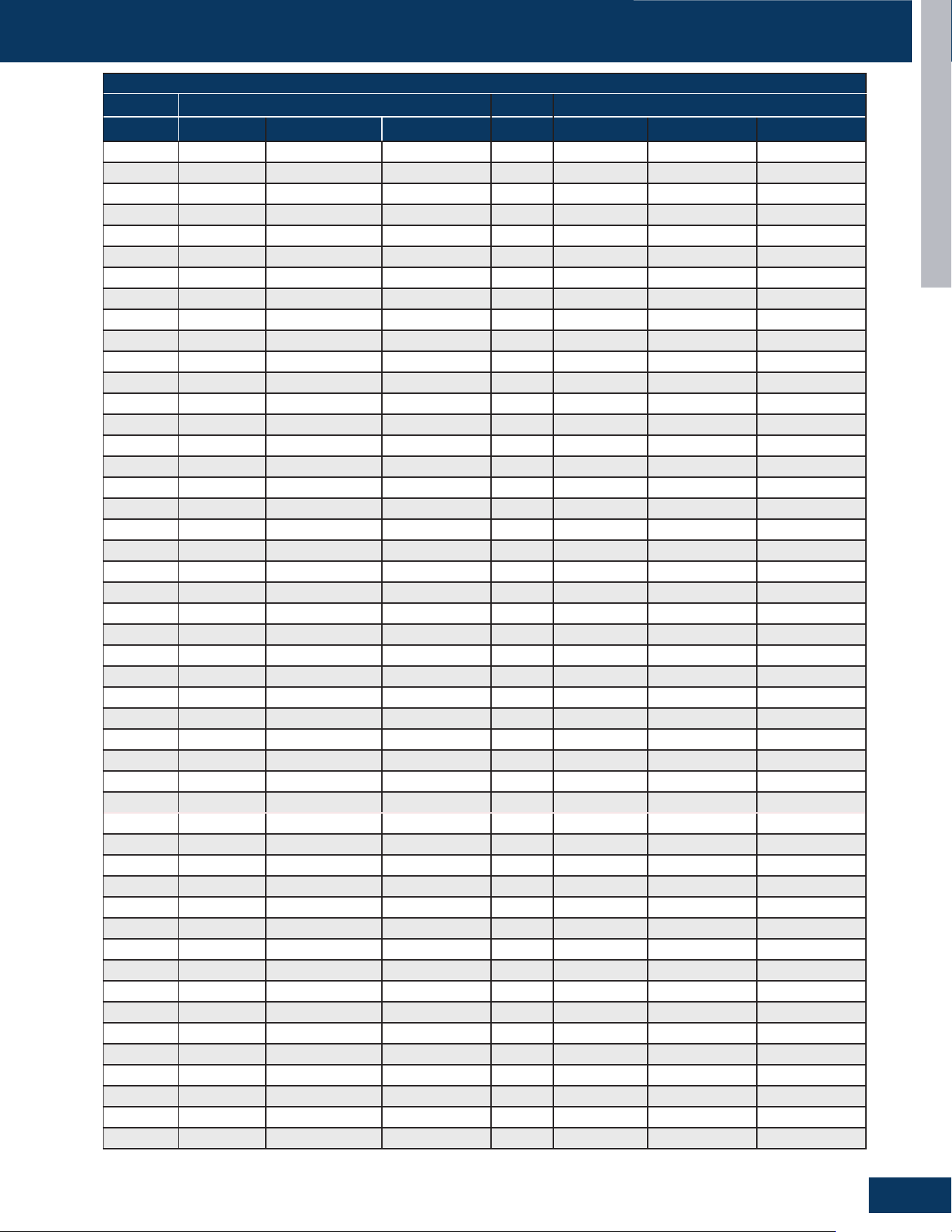
TROUBLESHOOTING AND REFERENCE
G17
ENGLISH
SENSOR RESISTANCE TABLES
B25/80=4450K±3%R80=50KΩ±3%
Temp Resistance(KΩ) Temp Resistance(KΩ)
(°C) Rmax R (t) Normal Rmin (°C) Rmax R (t) Normal Rmin
8 1326.746 1223.935 1121.124 59 117.641 112.494 107.347
9 1255.774 1159.265 1062.756 60 112.879 108.018 103.157
10 1189.098 1098.474 1007.850 61 108.332 103.741 99.150
62 103.989 99.654 95.319 107 20.667 19.720 18.773
63 99.841 95.748 91.655 108 20.020 19.091 18.162
64 95.879 92.014 88.149 109 19.397 18.485 17.573
65 92.091 88.443 84.795 110 18.795 17.900 17.005
66 88.472 85.028 81.584 111 18.215 17.337 16.459
67 85.011 81.761 78.511 112 17.655 16.793 15.931
68 81.703 78.636 75.569 113 17.114 16.268 15.422
69 78.538 75.645 72.752 114 16.593 15.763 14.933
70 75.510 72.781 70.052 115 16.090 15.275 14.460
71 72.614 70.040 67.466 116 15.603 14.804 14.005
72 69.842 67.415 64.988 117 15.133 14.349 13.565
73 67.189 64.901 62.613 118 14.681 13.911 13.141
74 64.649
62.493 60.337 119 14.243 13.488 12.733
75 62.216 60.185 58.154 120 13.821 13.080 12.339
76 59.886 57.973 56.060 121 13.412 12.685 11.958
77 57.653 55.852 54.051 122 13.019 12.305 11.591
78 55.515 53.820 52.125 123 12.638 11.938 11.238
79 53.465 51.870 50.275 124 12.271 11.584 10.897
80 51.500 50.000 48.500 125 11.917 11.242 10.567
81 49.684 48.206 46.728 126 11.573 10.911 10.249
82 47.940 46.484 45.028 127 11.243 10.593 9.943
83 46.267 44.832 43.397 128 10.923 10.285 9.647
84 44.659 43.246 41.833 129 10.614 9.988 9.362
85 43.114 41.723 40.332 130 10.315 9.701 9.087
86 41.629 40.260 38.891 131 10.028 9.425 8.822
87 40.203 38.856 37.509 132 9.750 9.158 8.566
88 38.831 37.506 36.181 133 9.481 8.900 8.319
89 37.513 36.209 34.905 134 9.222 8.651 8.080
90 36.244 34.962 33.680 135 8.972 8.411 7.850
91 35.025 33.764 32.503 136 8.731 8.180 7.629
92 33.851 32.612 31.373 137 8.498 7.957 7.416
93 32.722 31.504 30.286 138 8.273 7.741 7.209
94 31.636 30.439 29.242 139 8.055 7.533 7.011
95 30.590 29.413 28.236 140 7.846 7.333 6.820
96 29.583 28.427 27.271 141 7.628 7.125 6.621
97 28.614 27.478 26.342 142 7.417 6.923 6.429
98 27.680 26.564 25.448 143 7.213 6.728 6.243
99 26.781 25.685 24.589 144 7.014 6.538 6.062
100 25.914 24.838 23.762 145 6.822 6.355 5.888
101 25.080 24.023 22.966 146 6.636 6.178 5.719
102 24.275 23.237 22.199 147 6.455 6.006 5.556
103 23.500 22.481 21.462 148 6.280 5.839 5.398
104 22.753 21.752 20.751 149 6.111 5.678 5.244
105 22.031 21.049 20.067 150 5.946 5.521 5.096
106 21.336 20.372 19.408
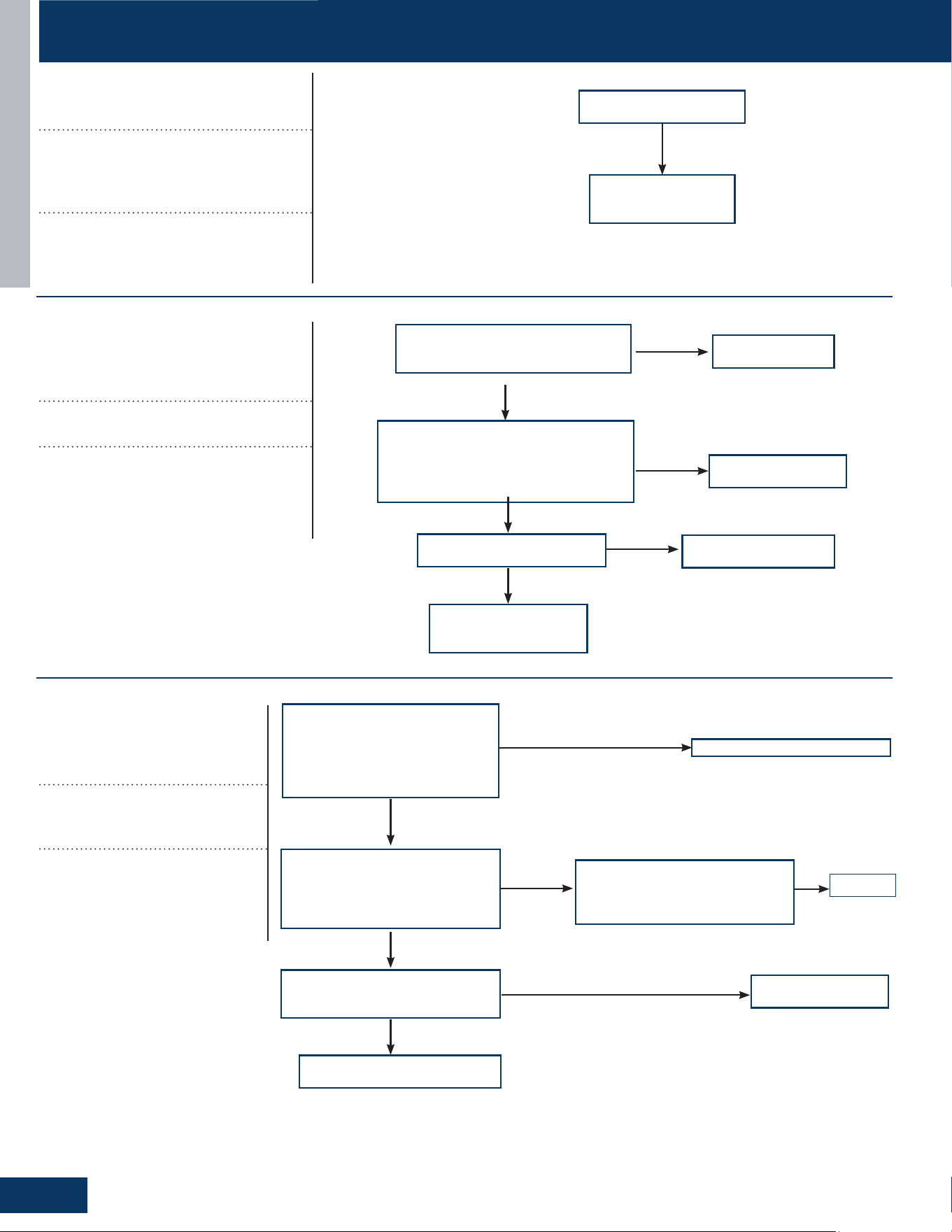
ERROR CODE TROUBLESHOOTING
TROUBLESHOOTING AND REFERENCE
G18
ENGLISH
Code disappears after
powero/onagain
Check outdoor
PCB, If faulty,
replace it.
No
Correct the wiring
Is electric box wiring correct,
andiscompressorwiringrmly
connected?
Is compressor normal (compressor
coil resistor, insulation)?
01507723090.73±5%Ω
01507720831.96±5%Ω
01507718650.49±5%Ω
Is power module normal?
Replace compressor
Replace power module
Yes
Yes
Yes
No
No
No
Solve or correct any
failures according to
relative information
Adjust communication wire
Is the compressor drive module
input power normal (Test the
AC power supply voltage of the
module’s power input ACL-ACN:
normal value should between 196-
253VAC)?
Check the AC voltage between
thetwoterminalsofpowerlter
board board P7& the terminal 3
of relay RL1 (208-230VAC)
Yes
Normal
No
Is the AC power supply wire
between compressor drive
moduleandlter
boardrmlyconnected?
Fix wiring
Abnormal
Check if the output of main
control board CN6,CN34 are
both DC 12V
No
Main control board
is bad, replace.
No
Thelterboardisbroken,
replacethelterboard
No
[1]
Outdoor EEPROM malfunction
EEPROM communication error; EEPROM
data check error (model ID, checksum,
etc.); EEPROM data logic error (wider data
range, wrong order, etc.)
Possible Causes:
• EEPROM is bad
• Loose EEPROM wiring
[2]
Compressor Drive Module’s IPM
overcurrent or short circuit
Input over current detected by PIM’s
hardware.
Possible Causes:
• The IPM is bad
• Loose compressor wire
• The compressor is bad
[4]
Communication abnormal
between PCB and IPM
Control board can not communi-
cate with the compressor driver
module for over 4 minutes
Possible Causes:
• The communication wire is bad
• The PCB is bad
• The power module is bad
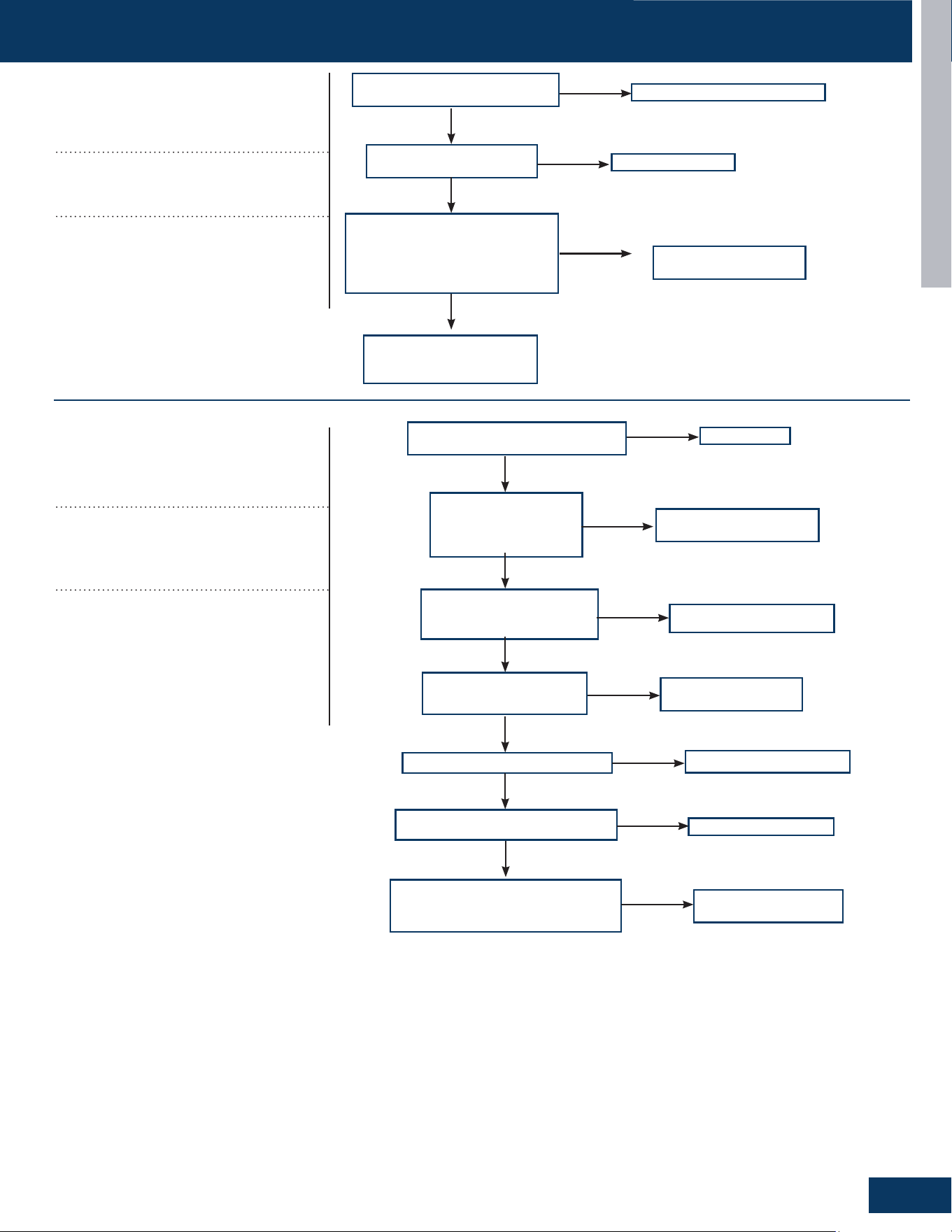
ERROR CODE TROUBLESHOOTING
TROUBLESHOOTING AND REFERENCE
G19
ENGLISH
Correct power supply
Is power supply voltage
normal?
Is electric box wiring
correct?
Is power module voltage
between terminal P&N more
than 390V or less than 160V
during operation?
Correct the wiring
Replace power module
Yes
Yes
No
No
Checkrectier,rector,
electrolytic capacitor on
inverter main circuit
No
Yes
[6]
Compressor Drive Module low or
high voltage
Driver module AC power supply voltage
over 280VAC, or driver module DC-BUS
voltage over 390VDC.
Possible Causes:
• The power supply is abnormal
• Incorrect wiring
• Power module is bad
[8]
Overheat protection for
discharge temperature
Compressor discharge temperature over
115°C. Error clears within 3 minutes if
temperature lowers below 115°C. Error
status lock if it occurs 3 times in 1 hour.
Possible Causes:
• The sensor is bad or xed bad
• The system is clogged
• The system lack of refrigerant
• The valve opening is wrong
• Check ODU fan motor is operating
Reconnect
Issensorwiringrmlyinplace?
Is sensor resistance
within range?
R25=10KΩ±3%
Is the system is clogged?
Is the PMV coil wiring ok?
Is stop valve is open?
Replace pressure switch
Check the piping system
Charge refrigerant
Check the piping system
Reconnect
Yes
No
Yes
Yes
No
Yes
No
No
Yes
No
No
Is the ambient temperature too
high?
Replace connecting
board
Yes
No
Is the system low on
refrigerant?

ERROR CODE TROUBLESHOOTING
TROUBLESHOOTING AND REFERENCE
G20
ENGLISH
Replace wire and test again
Are the fan motor wires
conductive?
Is the motor running?
Poweroandrotatethe
fan motor by hand. Does
it turn freely?
Is the terminial voltage correct?
The voltage between each phase of
the UVC should be balanced, and the
dierenceisnotmorethan5V.
The resistance between each phase
0010401832U 29±8%Ω
0150401754E 19.7±7%Ω
0150411775 20.5±10%Ω
Replace PCB
Replace fan motor
Replace PCB
Yes
Yes
Yes
Yes
No
No
No
No
Replace fan motor
Replace sensor
Is the sensor wiring
rmlyandcorrectlyin
place?
Is the sensor resistance within
range?
TeR25=10KΩ±3%
TsR25=10KΩ±3%
TaR25=10KΩ±3%
TdR25=10KΩ±3%
Is the temperature
loop acquired by
the computer board
normal?
Replace sensor
Replace it.
No
No
Yes
Yes
Yes
[9]
DC fan motor fault
DC fan motor damaged, not connected,
or related circuit broken. Error status
conrms and locks if occurs 3 times within
30 minutes.
Possible Causes:
• Loose motor wiring
• The motor is bad
• The PCB is bad
[10]
Outdoor defrosting temp. sensor
Te abnormal
[11]
Suction temp.sensor Ts abnormal
[12]
Outdoor ambient temp. sensor Ta
abnormal
[13]
Discharging temp. sensor Td
abnormal
Sensor temperature has been detected
below or higher than expected, or has
been detected as a shorted or open circuit
(for expected temperature, refer to part
failure code)
Possible Causes:
• Bad sensor connection
• The sensor is bad
• Sensor resistance drift
• The temperature acquired by PCB is not
accurate
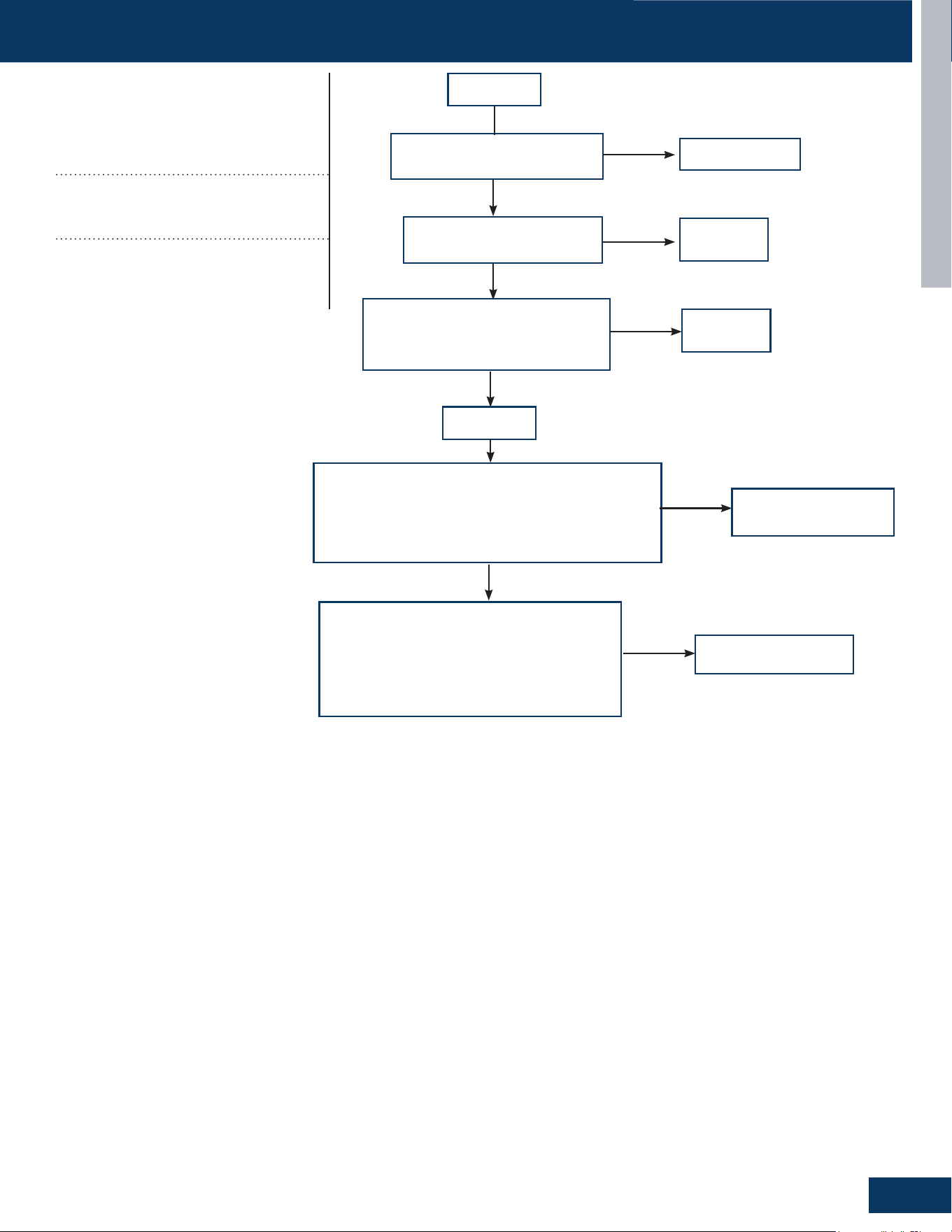
ERROR CODE TROUBLESHOOTING
TROUBLESHOOTING AND REFERENCE
G21
ENGLISH
Replace wire
Is the communication wire is
shorted?
Is the communication wire
CN21 is disconnected?
Reconnect
Reconnect
Yes
No
No
Yes
Is the wiring connection sequence
correct according to the wiring
diagram?
No
Measure the outdoor terminal block voltage
between communication 3 and N, and measure the
indoor terminal block between communication 3
and N to check. Is the communication wire ok?
Yes
Replace the
communication wire
Powero
Power on
No
Yes
Using a multimeter, measure the terminal
corresponding to the N-line voltage
of CN21 from the indoor unit with the
communication failure. Is the voltage
normal?
No
PCB is bad, replace
PCB
[15]
Communication abnormal
between indoor unit and outdoor
unit DC fan motor fault
Outdoor unit control board cannot
communicate with the indoor unit control
board for over 4 minutes.
Possible Causes:
• Bad communication wiring
• The PCB is bad
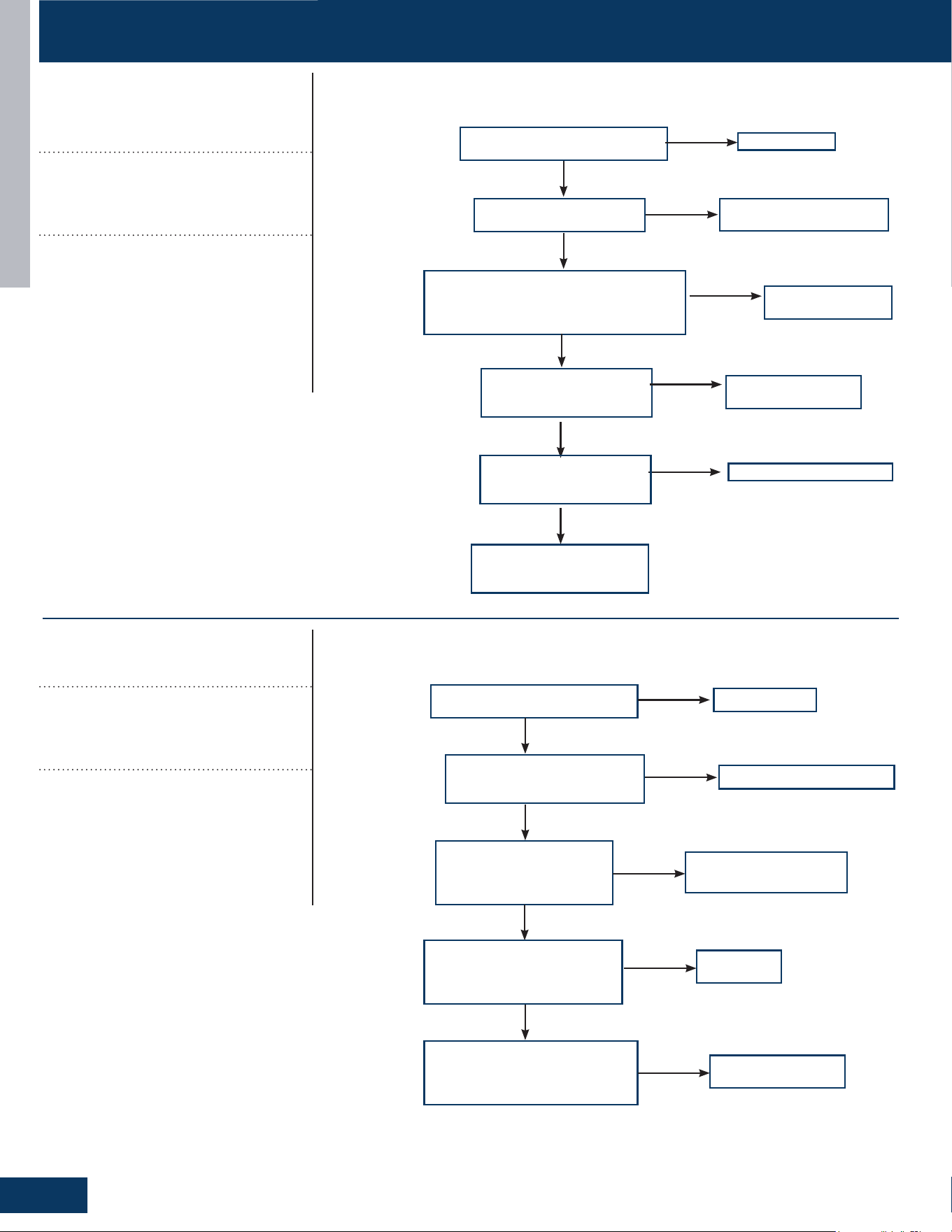
ERROR CODE TROUBLESHOOTING
TROUBLESHOOTING AND REFERENCE
G22
ENGLISH
Correct wiring
Is the sensor wiring correct
andrmlyconnected?
Is the system leaking, or
lacking refrigerant?
Is the resistance of the Td and the Tcm
sensors within range?
TdR25=10KΩ±3%
TcmR25=10KΩ±3%
Repair leak and recharge
refrigerant
Replace the sensor
Yes
No
Yes
No
Use the unit according to
the allowable operating
range of the unit.
Yes
Is there an Internal
leakage in the 4-way
valve?
No
Replace 4-way valve
Yes
No
Adjust the valve opening
Yes
Is the electronic
expansion valve over
throttled?
Reconnect
Is connection between the
4-way valve and PCB is good?
Is the 4-way valve coil
wiringrmlyinplaceand
characteristics correct?
Is the system meeting
4-way valve reversing
conditions (Pd-
Ps>0.6Mpa)?
Is there air noise after 4-way
valve reverses, and the temp.
of connection pipes on 4-way
valve normal?
Correct wiring or replace
Check if the
compressor is running
Replace PCB
Replace 4-way valve
Yes
Yes
Yes
No
Yes
No
No
Yes
No
Is 208/230VAC Measured on
PVB CN5 PCB after 4-way
valve reversing conditons are
met?
[16]
Lack of refrigerant or discharging
pipe blocked
Discharge & suction temperature Td-
Ts≥80°C 10 minutes after compressor
start. Error status locks if it occurs 3 times
in 1 hour.
Possible Causes:
• Wrong sensor connection
• Lack of refrigerant
• The senor is bad
• The 4-way valve is bad
• The electronic expansion valve is bad
• Out of the operating range
[17]
4-way valve reversing failure
Indoor pipe & indoor ambient temperature
Tm-Tai≥5°C 10 minutes after compressor
started. Error status locks if it occurs 3
times in 1 hour.
Possible Causes:
• The 4-way valve is bad
• The PCB is bad
• The 4-way valve coil connection is bad
• The system pressure dierence is too
small.
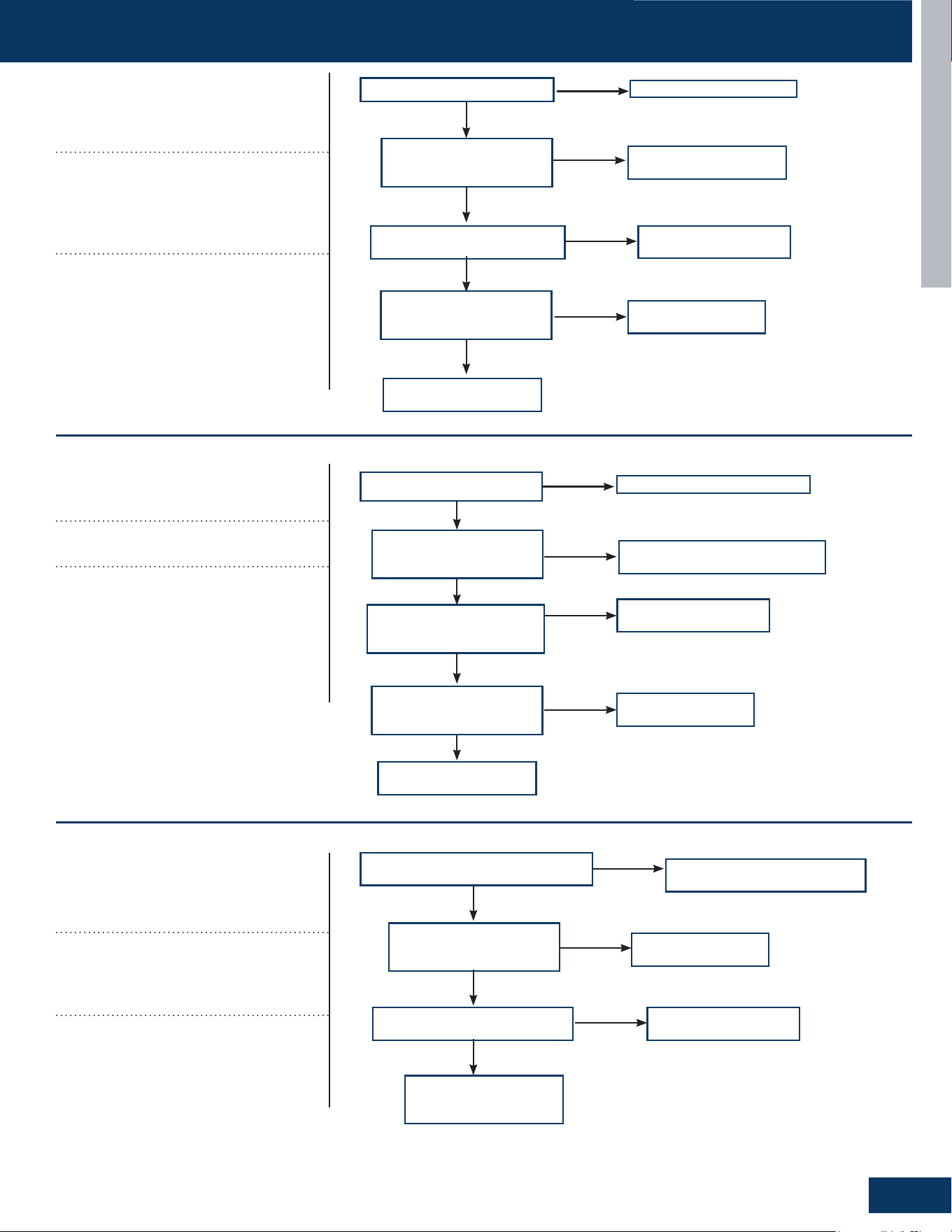
ERROR CODE TROUBLESHOOTING
TROUBLESHOOTING AND REFERENCE
G23
ENGLISH
Correct power supply
Is supply voltage normal?
Is wire connection
between power module
and compressor correct?
Is power module is normal?
Correct the wiring
according to diagram
Replace power module
Yes
Yes
Yes
No
No
No
Is compressor normal
(compressor coil resistor,
insulation)?
Replace compressor
Yes
No
Compressor load is too
high,ndthereason
Correct power supply
Is supply voltage normal?
Is wiring between power
module and compressor
correct?
Is power module is
normal?
Correct the wiring according
to diagram
Replace power module
Yes
Yes
No
No
Compressor load too
high,ndthereason
Yes
Is compressor is normal
(compressor coil resistor,
insulation)?
No
Replace compressor
No
Correct the wiring according
to diagram
Is electric box and compressor
wiringcorrectandrmlyinplace?
Is compressor normal
(compressor coil resistor,
insulation)?
Is power module is normal?
Replace compressor
Replace power module
Yes
Yes
Yes
No
No
No
Solve or correct any
failures according to
relative information
[18]
Compressor motor
desynchronizing
Motor desynchronizing occurred. Caused
by overload, load sharply uctuating, ab-
normal compressor current sensor circuit,
or one of the inverter gate drive signals is
missing.
Possible Causes:
• The power supply is abnormal
• Incorrect compressor wiring
• The power module is bad
• The compressor is bad
• The system is overload
[24]
Compressor startup failure
Compressor start failure has been detect-
ed by driver module.
Possible Causes:
• The power supply is abnormal
• Incorrect compressor wiring
• The power module is bad
• The compressor is bad
• System overload
[25]
Input overcurrent of the drive
module
Compressor drive module input current
higher than 32A (double fan model), or
27A (single fan). Locks if it occurs 3 times
in 1 hour.
Possible Causes:
• Incorrect compressor wiring
• The power module is bad
• The compressor is bad
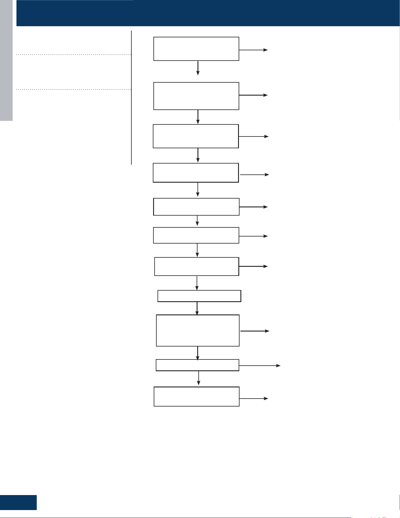
ERROR CODE TROUBLESHOOTING
TROUBLESHOOTING AND REFERENCE
G24
ENGLISH
Reconnect
Power o, check if the
pressure switch connection
is ok
Use multimeter to check
if the high pressure witch
terminal is short circuit
Check if the EEV coil is
xed well
Check if stop valve is
open
Use the multimeter to check if
the resistance of Tc & Tm is ok
Check if the piping system is
clogged
Check if the connection pipe
is bent
The pressure is
borken,replace it.
Open the stop valve
Clean the piping system
Replace the connection pipe
Replace the sensor
Yes
Yes
No
Yes
Yes
No
No
No
No
No
Yes
No
No
Reconnect the EEV
coil
Power on
Short high pressure
switch terminal on the
PCB to check if the system
reports failure
Check if fan motor is ok
Check if the resistance
of Te and Tc is ok
The PCB is
borken,replace it.
Replace sensor
No
Yes
Yes
Yes
No
No
Replace the fan
motor
[42]
Open high pressure switch
High pressure switch: Switch circuit has
been detected open for 30 seconds (after
3 minute of compressor run time). Error
locks if it occurs 3 times in 1 hour.
Possible Causes:
• Incorrect pressure switch wiring
• Abnormal system pressure
• System is clogged
• Incorrect refrigerant charge
• Bad valve
• Pressure switch is bad
• PCB is bad
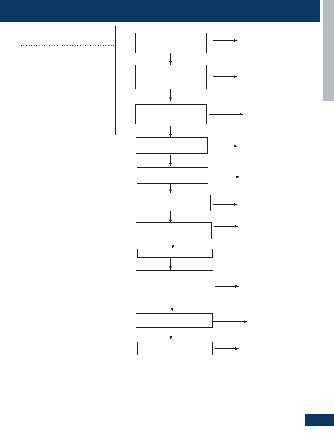
ERROR CODE TROUBLESHOOTING
TROUBLESHOOTING AND REFERENCE
G25
ENGLISH
Reconnect
Power o, check if the
pressure switch connection
is ok
Use multimeter to check
if the low pressure witch
terminal is short circuit
Check if the EEV coil is
xed well
Check if stop valve is
open
Use the multimeter to check if the
resistance of Tc & Tm is ok
Check if the piping system is
clogged
Check if the connection pipe is
bent
The pressure is
borken,replace it.
Open the stop valve
Clean the piping system
Replace the connection pipe
Replace the sensor
Yes
Yes
No
Yes
Yes
No
No
No
No
No
Yes
No
No
Reconnect the EEV
coil
Power on
Short high pressure switch
terminal on the PCB to check if
the system reports failure
Check if fan motor is ok
Check if the resistance
of Te and Toci is ok
The PCB is
borken,replace it.
Replace sensor
No
Yes
Yes
Yes
No
No
Replace the fan
motor
[43]
Open low pressure switch
Low pressure switch: Switch has been
detected open for 60 seconds (after 3
minute of compressor run time) or open
for 30 seconds during standby. Possible
Causes:
• Incorrect pressure switch wiring
• Abnormal system pressure
• System is clogged
• Incorrect refrigerant charge
• Bad valve
• Pressure switch is bad
• PCB is bad
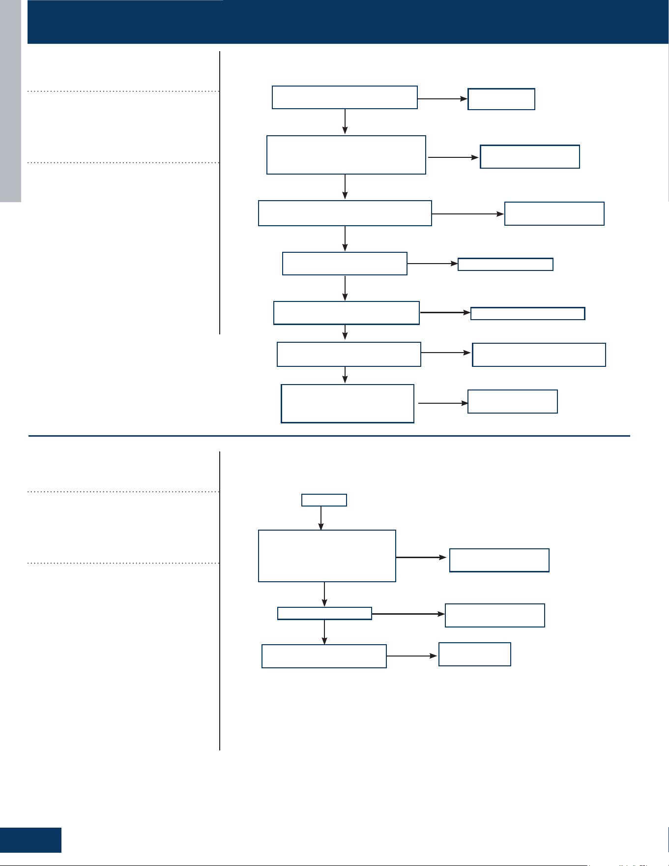
ERROR CODE TROUBLESHOOTING
TROUBLESHOOTING AND REFERENCE
G26
ENGLISH
Reconnect
Powero.Ispressureswitch
wiring connection ok?
Use multimeter to check the high
pressure switch. Is the switch
short circuited?
Is the EEV coil wiring correct and
rmlyinplace?
Is the stop valve is open?
Use a multimeter to check
the resistance of Tc & Tm.
Are they withing range?
Is the piping system is
clogged?
Check piping for any kinks or
damaged piping.
The pressure is bad,
replace it.
Open the stop valve
Clean the piping system
Replace the connection pipe
Replace the sensor
Yes
Yes
No
Yes
Yes
No
No
No
No
No
Yes
No
No
Reconnect the EEV
coil wiring
Power on
Short the low pressure
switch terminal on the PCB.
Does the system report a
failure?
Is the fan motor ok?
Is the resistance of Te and
Tc2 in range?
The PCB is bad,
replace it.
Replace sensor
No
Yes
Yes
Yes
No
No
Replace the fan
motor
[44]
High pressure detected in system
The minimum temperature value of indoor
pipe Tm and outdoor Ts is lower than -45
°C during cooling mode, or minimum tem-
perature value of outdoor Tc and outdoor
Te is lower than -45 °C.
Possible Causes:
• High pressure sensor detection value is
incorrect
• Refrigerant overcharge
• Blocked liquid line piping
• The outdoor unit cannot be turned on
normally due to failure to open outdoor
heat exchanger electronic expansion
valve when heating.
• The operation environment is beyond
the allowed range.
[45]
Low pressure detected in system
The minimum temperature value of indoor
pipe Tm and outdoor Ts is lower than -45
°C during cooling mode, or minimum tem-
perature value of outdoor Tc and outdoor
Te is lower than -45 °C.
Possible Causes:
• Low pressure sensor detection value is
incorrect
• Low refrigerant charge
• System air leakage
• Blocked low pressure or liquid line piping
• The outdoor unit cannot be turned on
normally due to failure to open outdoor
heat exchanger electronic expansion
valve when heating.
• The operation environment is beyond
the allowed range.
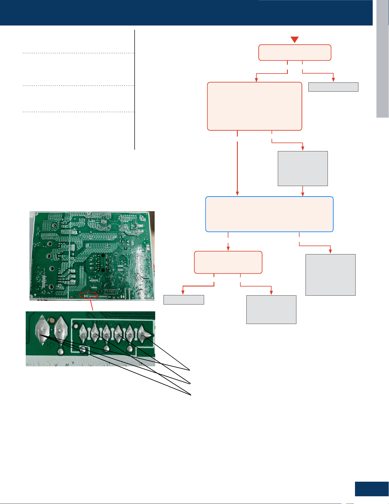
ERROR CODE TROUBLESHOOTING
TROUBLESHOOTING AND REFERENCE
G27
ENGLISH
TROUBLESHOOTING & REFERENCE
D-3
ENGLISH
TROUBLESHOOTING FLOWCHARTS
Error Code
Indoor)
Detection Conditions:
• Thermistor input is more than 4.92V or less than 0.08V during
compressor operation
Possible Causes:
• Faulty connector connection
• Faulty thermistor
• Faulty PCB
Yes
Yes
Yes
Yes
No
No
No
Re-seat connector
Replace sensor. Go
to next step to test
the board as well
before replacing
sensor.
No
Replace main board.
Replace sensor as
well if resistance
was incorrect in the
previous step.
Re-seat and
re-check sensor
resistance with a
different meter.
Replace sensor
Start
Is connector plugged in and
seated securely?
Disconnect power and unplug senor
connector from the board.
Check resistance across the set of
wires for the faulting sensor. Does
the resistance correspond to the
temperature located in the respective
chart?
Reconnect sensor to the board and re-apply power.
Check voltage between the two corresponding solder
joints or through the top of the Molex connector
depending on sensor confıguration.
Is the voltage ~5VDC?
Is the temperature at the
sensor out of operating
range (+/- 3%)?
5V Discharge Temperature Sensor
5V Defrost Temperature Sensor
5V Ambient Temperature Sensor
E1/LED1: No Flash
Room Temperature Sensor Failure
E2/LED1: No Flash
Indoor Coil Temperature Sensor Failure
E1/LED1: No Flash
Room Temperature Sensor Failure
E2/LED1: No Flash
Indoor Coil Temperature Sensor
Failure
Thermistor input is more than 4.92V or
less than 0.08V during compressor oper-
ation
Possible Causes:
• Faulty connector connection
• Faulty thermistor
• Faulty PCB
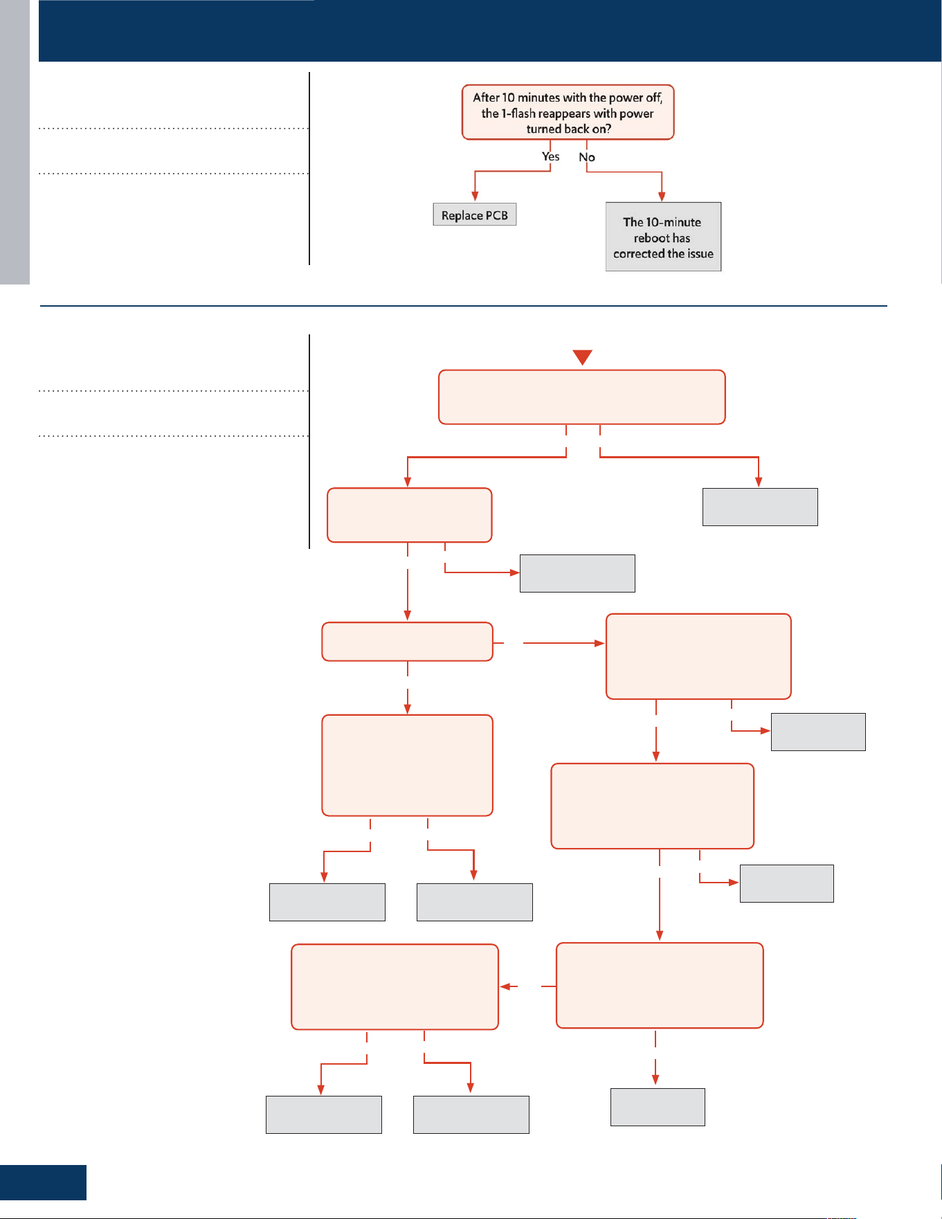
ERROR CODE TROUBLESHOOTING
TROUBLESHOOTING AND REFERENCE
G28
ENGLISH
TROUBLESHOOTING & REFERENCE
C-4
ENGLISH
TROUBLESHOOTING FLOWCHARTS
Error Code(Indoor)
E14
Indoor Fan Motor Failure
Complete the “Check This First” Flow Chart
before continuing.
Detection Conditions:
• No rotation feedback signal detected for
2 minutes
Possible Causes:
• Faulty fan motor
• Fan motor overheat protection
• Detection error due to faulty indoor unit
PCB
Yes
Yes
Yes
Yes
No
Yes No
No
Fix incoming power
supply
Replace the fan
motor
Replace the main
board.
Replace the fan
motor
Replace the
main board.
Replace the
main board.
Replace the
main board.
Start
With the power off, turn the
fan by hand. Does it move /
rotate smoothly?
Check the incoming voltage. Is it 208/230VAC (+/-
10%) between L1/L2? 104/230VAC (+/- 10%) from
L1 to GROUND and L2 to GROUND?
Re-apply power. Does the fan
come on and spin?
Measure DC voltage at fan
motor plug CN9 between
the Pin 7 (BLUE) and Pin 4
(BLACK) wire while spinning
the fan motor.
Does it generate 2~9VDC?
Measure DC voltage at fan
motor plug CN9 between Pin 1
(RED) and Pin 4 (BLACK).
Does it measure 300~380VDC
(+/-10%)?
Measure DC voltage at fan motor
plug CN9 between Pin 5 (WHITE)
and Pin 4 (BLACK).
Does it measure between
13.5-16.5VDC?
No
No
No
Yes
Replace the main
board.
Replace the fan
motor
Measure DC voltage at fan motor
plug CN9 between Pin 6 (YELLOW)
and Pin 4 (BLACK).
Does it measure between 2-6VDC?
Measure DC voltage at fan motor
plug CN9 between the Pin 7 (BLUE)
and Pin 4 (BLACK) wire while
spinning the fan motor.
Does it generate 2~9VDC?
No
Yes
No
Yes
31-5000931 Rev. 0
E4
Indoor EEPROM Error
EEPROM data error or the EEPROM is
damaged
Possible Causes:
• Faulty EEPROM data
• Faulty EEPROM
• Faulty PCB
E14
Indoor Fan Motor Failure
No rotation feedback signal detected for
2 minutes
Possible Causes:
• Faulty fan motor
• Fan motor overheat protection
• Detection error due to faulty indoor unit
PCB
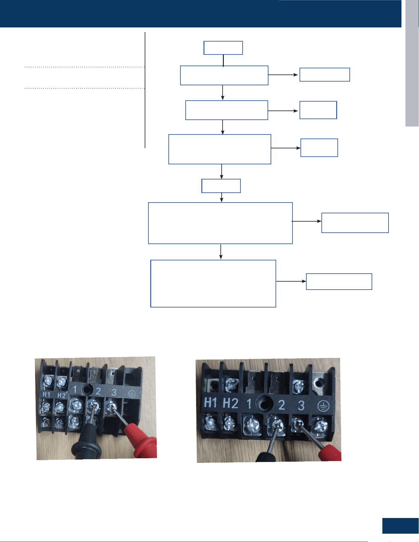
ERROR CODE TROUBLESHOOTING
TROUBLESHOOTING AND REFERENCE
G29
ENGLISH
TROUBLESHOOTING & REFERENCE
C-8
ENGLISH
TROUBLESHOOTING FLOWCHARTS
Error Code
(Indoor/Outdoor)
E7/LED1: 15 Flash
ID and OD Loss of
Communication
Detection Conditions:
• Outdoor PCB communication failure
• Indoor PCB communication failure
Possible Causes:
• Communication wiring disconnected
• Faulty indoor PCB
• Faulty outdoor PCB
• Faulty Outdoor Fan (may cause
communication signal interference)
31-5000931 Rev. 0
Replace wire
Is the communication wire is
shorted?
Is the communication wire
CN23 is disconnected?
Reconnect
Reconnect
Yes
No
No
Yes
Is the wiring connection sequence
correct according to the wiring
diagram?
No
Measure the outdoor terminal block voltage
between communication 3 and 2, and measure the
indoor terminal block between communication 3
and 2 to check. Is the communication wire ok?
Yes
Replace the
communication wire
Power o
Power on
No
Yes
Using a multimeter, measure the terminal
corresponding to the N-line voltage of CN21
from the indoor unit with the communication
failure. Is the voltage normal?
No
PCB is bad, replace PCB
outdoor terminal
indoor terminal
E7/LED1: 15 Flash
ID and OD Loss of
Communication
• Outdoor PCB communication failure
• Indoor PCB communication failure
Possible Causes:
• Communication wiring disconnected
• Faulty indoor PCB
• Faulty outdoor PCB
• Faulty Outdoor Fan (may cause commu-
nication signal interference)
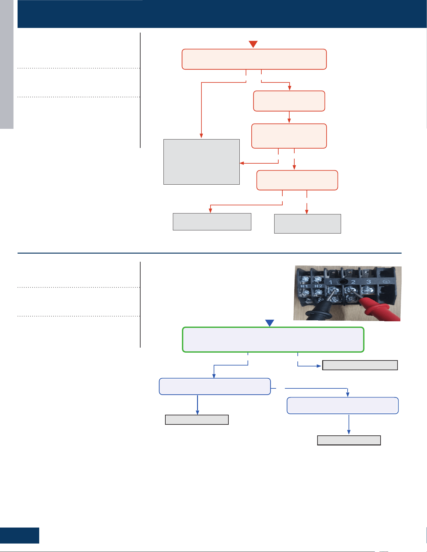
ERROR CODE TROUBLESHOOTING
TROUBLESHOOTING AND REFERENCE
G30
ENGLISH
No
Error Code (Indoor/Outdoor)
LED1: 28 Flash
Ye s
No
Refilling refrigerant
Start
Measure the current between 1/2
Is it 0.6A - 2.5A?
Replace the Coil
Ye s
Lack of refrigerant or discharging
Detection Conditions:
Possible Causes:
• Coil
leakag
e
•
Discharge refrigeran
t
•
Compressor operation frequency
more than 46Hz,thecurrent between
0.6A and 2.5A
Replace the PCB
Check the coil leakage
Check the coil leakage
Check the discharge refrigerant
ENGLISH
TROUBLESHOOTING FLOWCHARTS
C-9
TROUBLESHOOTING & REFERENCE
31-5000931 Rev. 0
Error Code (Indoor/Outdoor)
F27/LED1: 21 Flash
COMPRESSOR Block FAULT
It is compressor block fault, the compressor will not work when this fault happen.
Possible Causes:
Ambinent temperature is too low
Compressor damage
It also can be self recovery when this fault happen
Error Code(Indoor)
E22/LED1: 21 Flash
Indoor Unit Anti
-
frosting
protection
(cooling Mode Only)
Detection Conditions:
• Activated when the temperature being sensed by
the heat exchanger pipe sensor rises under 36
O
F
twice in 30 minutes.
Possible Causes:
• Faulty electronic expansion valve
• Dirty heat exchanger
• Faulty heat-exchange sensor
• Refrigerant undercharge
Note: this is a resetting fault that will not lockout operation.
No
No
Yes
Yes No
Start
Cycle power to the outdoor unit. Turn system on via
remote control. Does the error occur immediately?
Allow system to run until
error code is displayed
Troubleshoot the pipe
temperature sensor and
temperature monitoring
circuit of the indoor main
board. Replace components
found faulty.
Service the fan or clean
fılters as necessary.
Measure system charge level
and adjust as required.
Yes
Is the pipe at the location of
the pipe temperature sensor
under 36
O
F?
Is fan motor running properly
and fılters unobstructed?
TROUBLESHOOTING & REFERENCE
C-9
ENGLISH
TROUBLESHOOTING FLOWCHARTS
Error Code(Outdoor)
LED1: 21 Flash
Indoor Unit Over Temperature
(Heating Mode Only)
Detection Conditions:
• Activated when the temperature being sensed by
the heat exchanger pipe sensor rises above 149
O
F
twice in 30 minutes.
Possible Causes:
• Faulty electronic expansion valve
• Dirty heat exchanger
• Faulty heat-exchange sensor
• Refrigerant undercharge
No
No
Yes
Yes No
Start
Cycle power to the outdoor unit. Turn system on via
remote control. Does the error occur immediately?
Allow system to run until
error code is displayed
Troubleshoot the pipe
temperature sensor and
temperature monitoring
circuit of the indoor main
board. Replace components
found faulty.
Service the fan or clean
fılters as necessary.
Measure system charge level
and adjust as required.
Yes
Is the pipe at the location of
the pipe temperature sensor
above 149
O
F?
Is fan motor running properly
and fılters unobstructed?
31-5000931 Rev. 0
Note: this is a resetting fault that will not lockout operation.
LED1: 21Flash
Indoor Unit Over Temperature
(Heating Mode Only)
Activated when the temperature being
sensed by the heat exchanger pipe sensor
rises above 149
O
F twice in 30 minutes.
Possible Causes:
• Faulty electronic expansion valve
• Dirty heat exchanger
• Faulty heat-exchange sensor
• Refrigerant undercharge
LED1: 28 Flash
Lack of refrigerant or discharging
Compressor operation frequency more
than 46Hz,the current between
0.6A and 2.5A
Possible Causes:
• Coil leakage
• Discharge refrigerant
Note: this is a resetting fault that will not lockout operation.
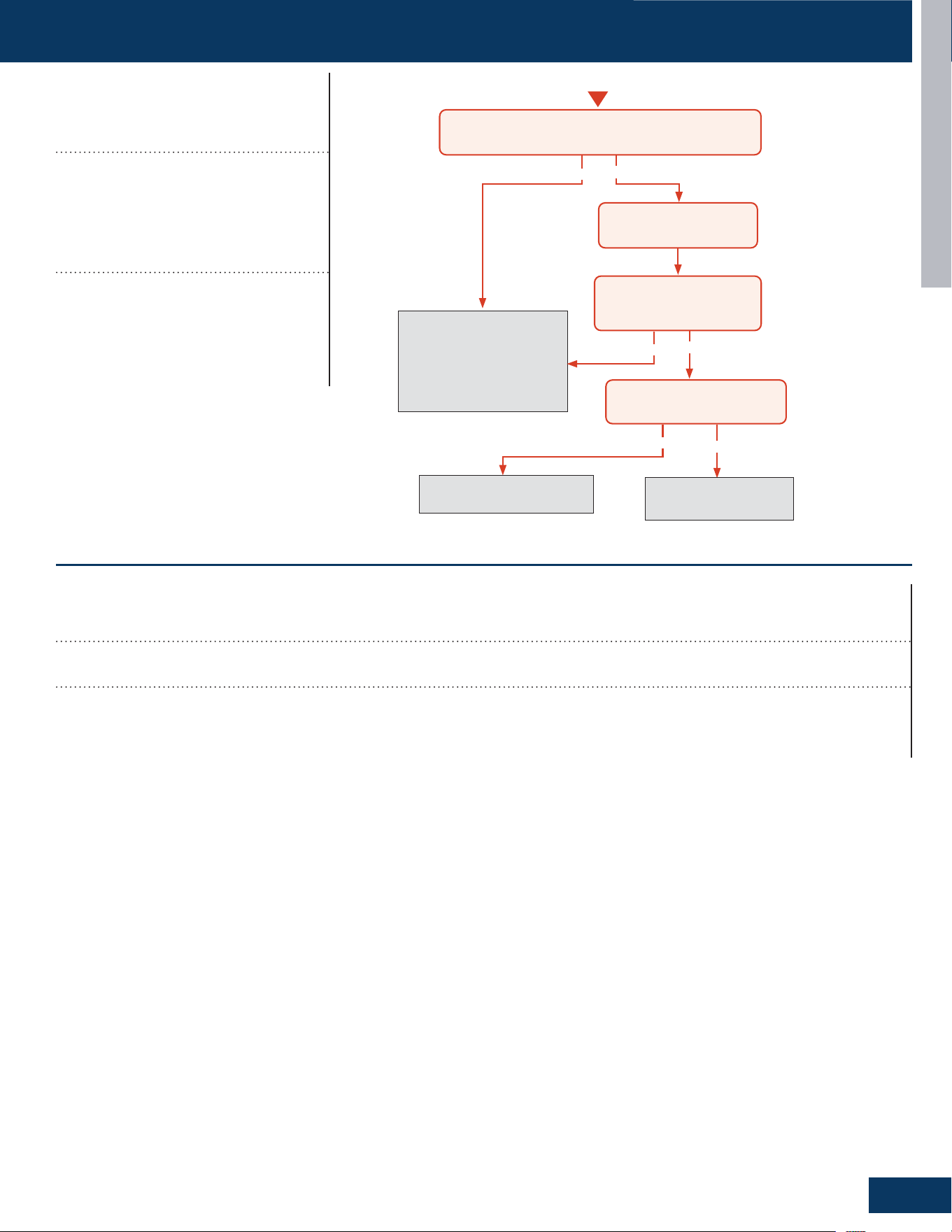
ERROR CODE TROUBLESHOOTING
TROUBLESHOOTING AND REFERENCE
G31
ENGLISH
No
Error Code (Indoor/Outdoor)
LED1: 28 Flash
Ye s
No
Refilling refrigerant
Start
Measure the current between 1/2
Is it 0.6A - 2.5A?
Replace the Coil
Ye s
Lack of refrigerant or discharging
Detection Conditions:
Possible Causes:
• Coil
leakag
e
•
Discharge refrigeran
t
•
Compressor operation frequency
more than 46Hz,thecurrent between
0.6A and 2.5A
Replace the PCB
Check the coil leakage
Check the coil leakage
Check the discharge refrigerant
ENGLISH
TROUBLESHOOTING FLOWCHARTS
C-9
TROUBLESHOOTING & REFERENCE
31-5000931 Rev. 0
Error Code (Indoor/Outdoor)
F27/LED1: 21 Flash
COMPRESSOR Block FAULT
It is compressor block fault, the compressor will not work when this fault happen.
Possible Causes:
Ambinent temperature is too low
Compressor damage
It also can be self recovery when this fault happen
Error Code(Indoor)
E22/LED1: 21 Flash
Indoor Unit Anti
-
frosting
protection
(cooling Mode Only)
Detection Conditions:
• Activated when the temperature being sensed by
the heat exchanger pipe sensor rises under 36
O
F
twice in 30 minutes.
Possible Causes:
• Faulty electronic expansion valve
• Dirty heat exchanger
• Faulty heat-exchange sensor
• Refrigerant undercharge
Note: this is a resetting fault that will not lockout operation.
No
No
Yes
Yes No
Start
Cycle power to the outdoor unit. Turn system on via
remote control. Does the error occur immediately?
Allow system to run until
error code is displayed
Troubleshoot the pipe
temperature sensor and
temperature monitoring
circuit of the indoor main
board. Replace components
found faulty.
Service the fan or clean
fılters as necessary.
Measure system charge level
and adjust as required.
Yes
Is the pipe at the location of
the pipe temperature sensor
under 36
O
F?
Is fan motor running properly
and fılters unobstructed?
E22/LED1: 21 Flash
Indoor Unit Anti- frosting
protection (Cooling Mode Only)
Activated when the temperature being
sensed by the heat exchanger pipe sensor
rises under 36
O
F twice in 30 minutes.
Compressor operation frequency more
than 46Hz, the current between
0.6A and 2.5A
Possible Causes:
• Faulty electronic expansion valve
• Dirty heat exchanger
• Faulty heat-exchange sensor
• Refrigerant undercharge
F27/LED1: 21 Flash
Compressor Current Sampling Circuit Fault
Detection Conditions:
It is compressor block fault, the compressor will not work when this fault happen. It also can be self recovery when this fault happens.
Possible Causes:
• Ambient temperature is too low
• Compressor damage
ERROR CODE TROUBLESHOOTING
TROUBLESHOOTING AND REFERENCE
G32
ENGLISH
Check if the wiring harness is damaged
Replace the wiring harness
Replace the leakage sensor
Check if the wiring harness has poor contact
Reconnect the wiring harness
Check if the PCB is damaged
Replace the PCB
Connect the leakage sensor
Check if the leakage sensor is disconnected with Indoor PCB
bA
DIP Switch Enabled, No Sensor Detected
Detection Conditions:
DIP Switch Enabled, No Sensor Detected
Possible Causes:
• Loose wiring terminals
• Damaged wiring harness
• The leakage sensor is not connected
• PCB damage
* Caution
Be sure to turn o power switch before connect or disconnect connector, or else parts damage may be occurred.
ERROR CODE TROUBLESHOOTING
TROUBLESHOOTING AND REFERENCE
G33
ENGLISH
Check for refrigerant leakage
Replace the indoor unit or weld
the pipeline
Replace the leakage sensor
AA and Ab
Refrigerant Leakage Fault
Detection Conditions:
• AA: Refrigerant concentration over 10% LFL
• Ab: AA display after 5 minutes and refrigerant concentration of less than 8% LFL detected
Possible Causes:
• Pipe cracking
• The union nut is not secured
* Caution
Be sure to turn o power switch before connect or disconnect connector, or else parts damage may be occurred.
ERROR CODE TROUBLESHOOTING
TROUBLESHOOTING AND REFERENCE
G34
ENGLISH
Check if the wiring harness is damaged
Replace the wiring harness
Replace the leakage sensor
Check if the wiring harness has poor contact
Reconnect the wiring harness
Check if the PCB is damaged
Replace the PCB
Ac
Leakage Sensor Communication Fault
Detection Conditions:
The communication between the leakage sensor and the PCB is faulty
Possible Causes:
• Loose wiring terminals
• Damaged wiring harness
• PCB damage
* Caution
Be sure to turn o power switch before connect or disconnect connector, or else parts damage may be occurred.
ERROR CODE TROUBLESHOOTING
TROUBLESHOOTING AND REFERENCE
G35
ENGLISH
Check if the sensor itself is damaged
Replace the leakage sensor
Replace the leakage sensor
Measure whether the sensor voltage is normal
Replace the PCB or leakage sensor
Check the temperature of the usage environment
Normal temperature range -35 to 80 degrees
Celsius
Ad
Leakage Sensor Self-Check Fault
Detection Conditions:
Leakage sensor self-test failed
Possible Causes:
• Power supply overvoltage and undervoltage (5VDC)
• The temperature value detected by the leakage sensor exceeds the limit value
• Internal sensor error
* Caution
Be sure to turn o power switch before connect or disconnect connector, or else parts damage may be occurred.
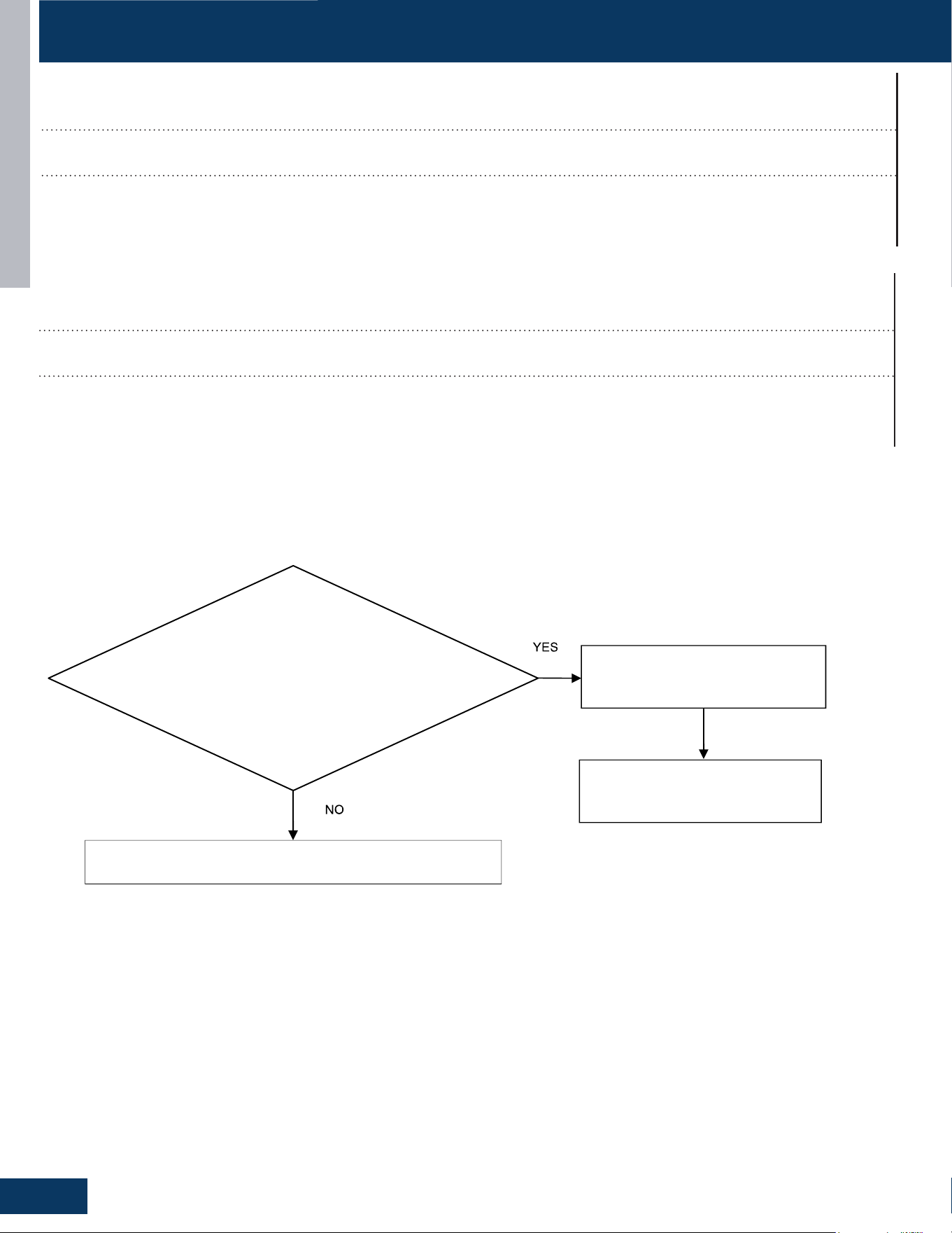
ERROR CODE TROUBLESHOOTING
TROUBLESHOOTING AND REFERENCE
G36
ENGLISH
Check the actual usage time of the sensor
Actual usage time reaches 14.5 years
The unit power cycle
Replace the leakage sensor
AE
Leakage Sensor Reaching-End-of-Life Warning
Detection Conditions:
The sensor is 6 months away from the end of its life
Possible Causes:
• The sensor approaching the end of life
• End of life counting error of sensor
* Caution
Be sure to turn o power switch before connect or disconnect connector, or else parts damage may be occurred.
AF
Leakage Sensor End- Of- Life
Detection Conditions:
The sensors have reached the end of life
Possible Causes:
• The sensor approaching the end of life
• End of life counting error of sensor

[This page intentionally left blank.]
Rev. 10-16-25
©Copyright 2025 GE Appliances, a Haier Company.
Our continued commitment to quality products may
meanachangeinspecicationswithoutnotice.
Ductless Technical Support
Phone: 866.814.3633
Email: HVACSupport@GEAppliances.com
Online: GEAppliancesAirAndWater.com