SERVICE, INSTALLATION AND OPERATION MANUAL
For AUTHORIZED PARTS or TECHNICAL SERVICE, please contact:
3355 Enterprise Avenue, Suite 160, Fort Lauderdale, FL 33331 USA
Phone: (954) 202-7419
Website: MaxximumFoodService.com
MVF29UHC MVR29UHC W/1 DOOR
MVF48UHC MVR48UHC W/2 DOOR
MVF60UHC MVR60UHC W/2 DOOR
UNDERCOUNTER REFRIGERATORS
PLEASE READ
CAREFULLY

Page 2 of 19
TABLE of CONTENTS
SERIAL NUMBER INFORMATION ............................................................................................................................................. 3!
APPLIANCE SAFETY .................................................................................................................................................................... 4!
IMPORTANT SAFEGUARDS ........................................................................................................................................................ 5!
DIMENSIONS .................................................................................................................................................................................. 7!
TECHNICAL INFORMATION ....................................................................................................................................................... 8!
RECEIVING AND INSPECTING THE EQUIPMENT .................................................................................................................. 9!
INTRODUCTION
........................................................................................................................................................................... 9!
COMPONENT INFORMATION
................................................................................................................................................10!
APPLIANCE INSTALLATION .................................................................................................................................................... 11!
Remove Packaging Materials ..................................................................................................................................................... 11!
Location Requirements ............................................................................................................................................................... 11!
Inside cabinet: ............................................................................................................................................................................. 11!
Outside cabinet: .......................................................................................................................................................................... 11!
Installation Clearance ................................................................................................................................................................. 12!
Leveling ...................................................................................................................................................................................... 12!
Stabilizing ................................................................................................................................................................................... 12!
Electrical Connection .................................................................................................................................................................. 12!
OPERATION .................................................................................................................................................................................. 13!
Refrigerated cycle ....................................................................................................................................................................... 13!
Power Switch: ............................................................................................................................................................................. 13!
SOLID-STATE THERMOSTAT DESCRIPTIONS ...................................................................................................................... 13!
1.
FRONT PANEL COMMANDS ............................................................................................................................................. 13!
2.
MAIN FUNCTIONS .............................................................................................................................................................. 14!
3.
ALARM SIGNALLING ......................................................................................................................................................... 15!
CLEANING AND MAINTENANCE ............................................................................................................................................ 16!
Exterior and Interior Cleaning of Appliances ............................................................................................................................. 16!
Cleaning the Condenser Coil ...................................................................................................................................................... 16!
Stainless Steel Care and Cleaning .............................................................................................................................................. 17!
Gasket Maintenance .................................................................................................................................................................... 17!
Doors/Hinges .............................................................................................................................................................................. 17!
Drain Maintenance ...................................................................................................................................................................... 17!
TROUBLESHOOTING GUIDE
................................................................................................................................................. 18!
TROUBLESHOOTING ................................................................................................................................................................. 18!
WIRING DIAGRAMS ................................................................................................................................................................... 19!
Page 3 of 19
READ THIS MANUAL IN ITS ENTIRETY
TO HELP FAMILIARIZE YOURSELF WITH YOUR NEW EQUIPMENT BEFORE PROCEEDING.
We have provided many important safety messages in this manual.
Always read and obey all safety messages.
Understanding of safety messages will assist in alerting you to potential hazards, as well as tell you
how to reduce the chance of injury. Follow the instructions as outlined in this manual.
VISIT OUR WEBSITE for the MOST UP-TO-DATE VERSION of this MANUAL.
http://www.maxximumfoodservice.com/
Fill out and return the enclosed warranty postcard or visit our website/warranty registration.
Keep the dated proof of purchase invoice which establishes the appliance's warranty period.
SERIAL #:______________________________________________________________________________________________
MODEL #:________________________________________ DATE OF PURCHASE:_______________________________
SERIAL NUMBER INFORMATION
l The serial number of all self-contained refrigerators is located inside the unit on the left hand side near the top on the
wall.
l Always have the serial number of your unit available when calling for parts or service.
l This manual covers standard units only. If you have a custom unit, consult customer service department at the number
listed on cover page.
Due to periodic changes in designs, methods, procedures, policies and regulations, the contents of this manual
are subject to change without notice. While we exercise good faith efforts to provide information that is accurate,
we are not responsible for errors or omissions in information provided or conclusions reached as a result of
using this reference manual. By using the information provided, the user assumes all risks in connection with
such use.
Page 4 of 19
APPLIANCE SAFETY
Always read and obey all safety messages.
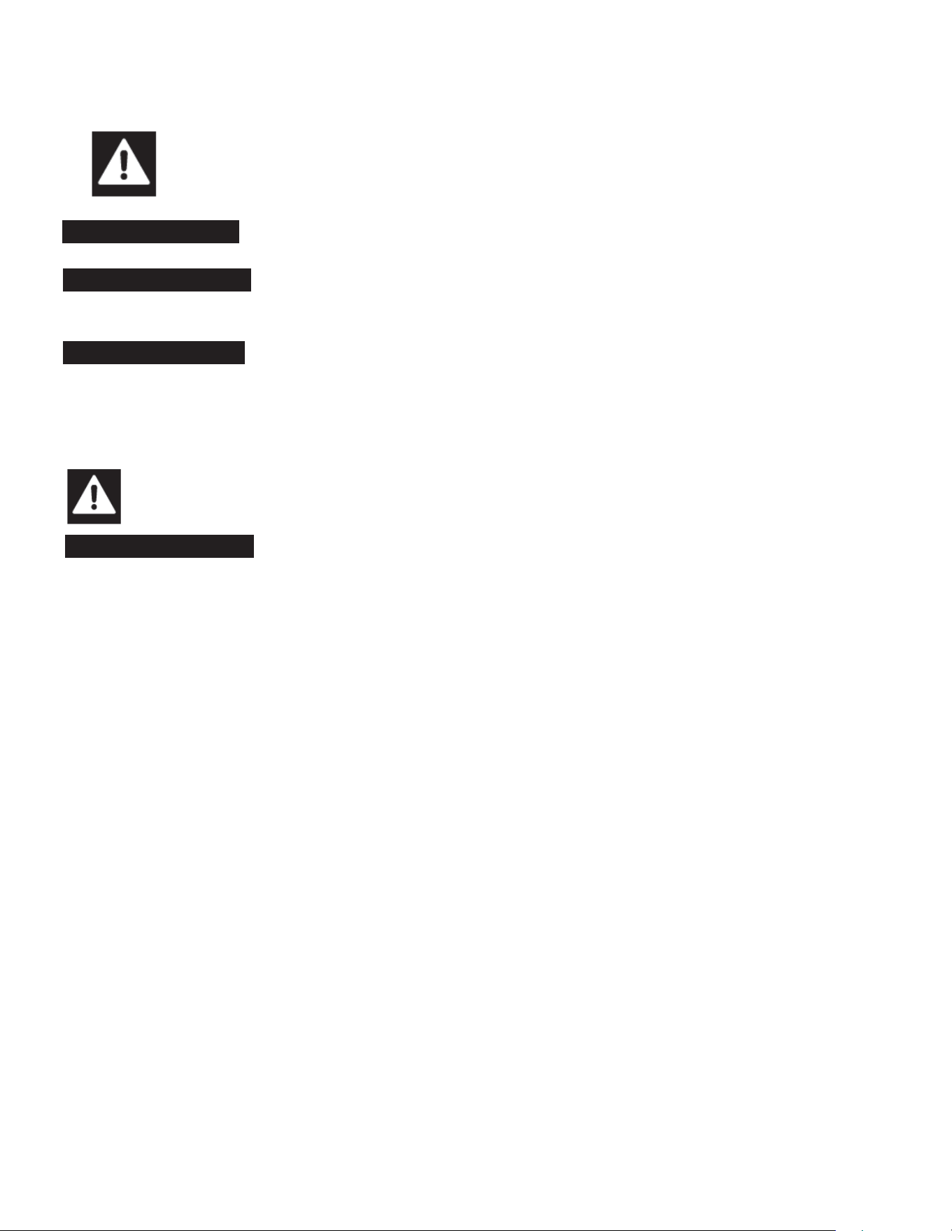
This is the Safety Alert Symbol. This symbol alerts you to potential hazards that can injure or kill you
and others. All safety messages will follow the Safety Alert Symbol and either the words “DANGER”,
“WARNING” OR “CAUTION”.
DANGER
DANGER means that failure to heed this safety statement may result in
Death or Severe Personnel Injury
.
WARNING
WARNING means that failure to heed this safety statement may result in extensive product damage, serious
personal injury, or death.
CAUTION
CAUTION means that failure to heed this safety statement may result in minor or moderate personal injury, or
property or equipment damage.
All safety messages will alert you to what the potential hazard is, tell you how to reduce the chance of injury, and let you
know what can happen if the instructions are not followed.
NOTE: IMPORTANT SAFETY INSTRUCTIONS
WARNING
To reduce the risk of fire, electric shock or injury, when using your
appliance
, follow these
basic precautions:
l
Plug into a tested grounded 3-prong outlet.
l
Do not remove grounding prong.
l
Do not use an adapter.
l
Do not use an extension cord.
l
Disconnect power before cleaning.
l
Disconnect power before servicing.
l
Use 2 or more people to safely move and install
appliance.
SAVE THESE INSTRUCTIONS

Page 5 of 19
IMPORTANT SAFEGUARDS
Before the
appliance
is used, it must be properly positioned and installed as described
in this manual, so read the manual carefully. We strongly recommend that you have a
professional install your new machine. The warranty may be affected or voided by
an incorrect installation. To reduce the risk of fire, electrical shock or injury when
using the
appliance
, follow basic precautions, including the following:
DANGER
•
It is recommended that a separate circuit, serving only your
appliance
, be provided. Use receptacles that cannot
be turned off by a switch or pull chain.
• Please ensure that the required voltage is being supplied at all times.
• The unit should be plugged into a grounded and properly-sized electrical outlet with appropriate over-current
protection.
• Ensure unit is not resting on, pinching or against the electrical cord.
•
Do not connect or disconnect the electric plug when your hands are wet.
•
Never unplug the
appliance
by pulling on the power cord. Always grip the plug firmly and pull straight out from the
outlet.
•
Never clean
appliance
parts with flammable fluids. Do not store or use gasoline or other flammable vapors and
liquids in the vicinity of this or any other appliance. The fumes can create a fire hazard or explosion.
•
Before proceeding with cleaning and maintenance operations, make sure the power line of the unit is disconnected.
•
Unplug the
appliance
or disconnect power before cleaning or servicing. Failure to do so can result in electrical
shock or death.
• If the unit is not in use for a long period of time, best to unplug the unit from the outlet.
• After unplugging the unit, wait at least 8 minutes before plugging it back in. Failure to do so could cause damage to the
compressor.
• If the
power cuts off, wait at least 8 minutes before turning the unit on to avoid damage to the compressor.
•
Do not attempt to repair or replace any part of your
appliance
unless it is specifically recommended in this manual. A
qualified technician should do all other servicing or repairs.
WARNING
• Use two or more people to move and install
appliance.
Failure to do so can result in back or other injury.
• This appliance must be properly installed and located in accordance with the Installation Instructions before it is used.
• Do not touch the cold surfaces in the cold compartment when hands are damp or wet. Skin may stick to these
extremely cold surfaces.
• Setting temperature controls to the ZERO (0) position does not remove power to the light circuit, perimeter heaters, or
evaporator fans.
•
To ensure proper ventilation for your
appliance
, choose a well-ventilated area with temperatures above 50ºF
(10ºC) and below 100ºF (38ºC). This unit MUST be installed in an area protected from the elements, such as
wind, rain, water spray or drips.
•
The
appliance
should not be located next to ovens, grills or other sources of high heat.
•
It is important for the
appliance
to be level for proper operation. You may need to make adjustments to level it.
•
Remove the packing materials and clean the
appliance
before using.
•
Do not use this apparatus for other than its intended purpose.

Page 6 of 19
IMPORTANT SAFEGUARDS (cont.)
Electrical Connection
Do not, under any circumstances, cut or remove the third (ground) prong from the power cord. For personal safety,
this appliance must be properly grounded. The power cord of this appliance is equipped with a 3-prong grounding
plug that mates with a standard 3-prong grounding wall outlet to minimize the possibility of electric shock hazard from
the appliance. Have the wall outlet and circuit checked by a qualified electrician to make sure the outlet is properly
grounded. The
appliance
should always be plugged into its own individual electrical outlet which has a voltage rating
that matches the rating label on the appliance. This provides the best performance and also prevents overloading
house wiring circuits which could cause a fire hazard from overheated wires. Repair or replace immediately all power
cords that have become frayed or otherwise damaged. Do not use a cord that shows cracks or abrasion damage along
its length or at either end. When moving the
appliance
, be careful not to damage the power cord.
Refrigerant Disposal
If you are throwing away your old appliance it may have a cooling system that uses “Ozone Depleting” chemicals. Make
sure the refrigerant is removed for proper legal disposal by a qualified service technician.
Page 7 of 19
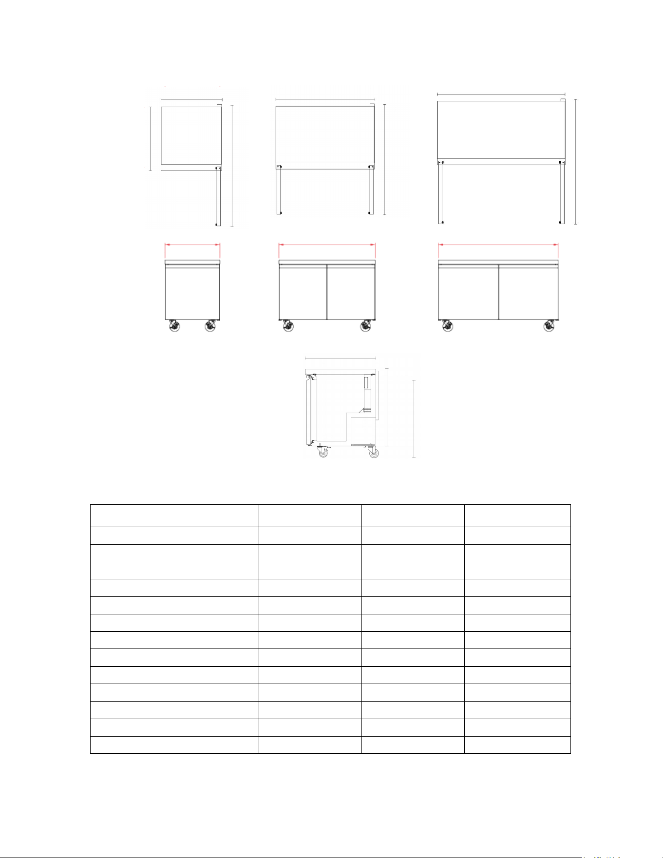
DIMENSIONS
TECHNICAL INFORMATION
Model
MVF29UHC
MVF48UHC
MVF60UHC
in: Exterior Dimension W*D*H
29 x 31.9 x 38 48 x 31.9 x 38 61 x 31.9 x 38
mm: Exterior Dimension W*D*H
735 x 810 x 966 1230 x 810 x 966 1555 x 810 x 966
in: Depth With Door(s) Open
57.8 53.2 59.6
mm: Depth With Door(s) Open
1467.5 1352.5 1514.5
in: Interior Dimensions W*D*H
24.8 x 22 x 28.8 44.3 x 22 x 28.8 57.1 x 22 x 28.8
mm: Interior Dimensions W*D*H
630 x 558.5 x 731 1125 x 558.5 x 731 1450.5 x 558.5 x 731
Nominal Capacity
7.74 Cu Ft / 219 L 14.1 Cu Ft / 399.4 L 18.5 Cu Ft / 524.6 L
Appliance Weight
132.3 lbs / 60 kg 181 lbs / 82 kg 209.4 lbs / 95 kg
Hinged Doors
1
2
2
Shelves
1
2
2
Electrical Service
115V/60Hz/1Ph
115V/60Hz/1Ph
115V/60Hz/1Ph
Refrigerant R290 R290 R290
Provided 6’ NEMA Cord Set 5-15 5-15 5-15
MVF29UHC
MVF48UHC
MVF60UHC
48 in (1230 mm)
61 in (1555 mm)
29 in (735 mm)
61 in (1555 mm)
48 in (1230 mm)
29 in (735 mm)
31.9 in (810 mm)
57.8 in (1467.5 mm)
53.2 in (1352.5 mm)
59.6 in (1514.5 mm)
33.1 in (841 mm)
38 in (966 mm)
31.9 in (810 mm)

Page 8 of 19
DIMENSIONS
TECHNICAL INFORMATION
Model
MVR29UHC
MVR48UHC
MVR60UHC
in: Exterior Dimension W*D*H 29 x 31.9 x 38 48 x 31.9 x 38 61 x 31.9 x 38
mm: Exterior Dimension W*D*H 735 x 810 x 966 1230 x 810 x 966 1555 x 810 x 966
in: Depth With Door(s) Open 57.8 53.2 59.6
mm: Depth With Door(s) Open 1467.5 1352.5 1514.5
in: Interior Dimensions W*D*H 24.8 x 22 x 28.8 44.3 x 22 x 28.8 57.1 x 22 x 28.8
mm: Interior Dimensions W*D*H 630 x 558.5 x 731 1125 x 558.5 x 731 1450.5 x 558.5 x 731
Nominal Capacity 7.74 Cu Ft / 219 L 14.1 Cu Ft / 399.4 L 18.5 Cu Ft / 524.6 L
Appliance Weight
141 lbs / 64 kg 176.4 lbs / 80 kg 207 lbs / 94 kg
Hinged Doors 1 2 2
Shelves 1 2 2
Electrical Service 115V/60Hz/1Ph 115V/60Hz/1Ph 115V/60Hz/1Ph
Refrigerant R290 R290 R290
Provided 6’ NEMA Cord Set 5-15 5-15 5-15
MVR29UHC
MVR48UHC
MVR60UHC
48 in (1230 mm)
61 in (1555 mm)
29 in (735 mm)
61 in (1555 mm)
48 in (1230 mm)
29 in (735 mm)
31.9 in (810 mm)
57.8 in (1467.5 mm)
53.2 in (1352.5 mm)
59.6 in (1514.5 mm)
33.1 in (841 mm)
38 in (966 mm)
31.9 in (810 mm)

Page 9 of 19
RECEIVING AND INSPECTING THE EQUIPMENT
Even though most equipment is shipped crated, care should be taken during unloading so the equipment is not damaged
while being moved into the building.
1. Visually inspect the exterior of the package and skid or container. Any damage should be noted and formally reported to the
delivering carrier as soon as possible within 10 days.
2. If damaged, open and inspect the contents with the carrier.
3. In the event that the exterior is not damaged, yet upon opening, there is concealed damage to the equipment, notify the
carrier. Notification should be made verbally as well as in written form.
4. Request an inspection by the shipping company of the damaged equipment. This should be done within 10 days from receipt
of the equipment.
5. Be certain to check the compressor compartment housing and visually inspect the refrigeration package. Be sure lines are
secure and base is still intact.
6. Freight carriers can supply the necessary damage forms upon request.
7. Retain all crating material until an inspection has been made or waived.
INTRODUCTION
This user’s manual is intended for installing, using and servicing your Maxx Cold Select Series Appliance. It is
recommended that this manual be kept in an accessible place. Every Maxx Cold machine is designed and
manufactured according to the highest standards of safety and performance. It meets or exceeds the safety standard of
UL 471 and sanitation standard NSF 7.
The Legacy Companies assumes no liability or responsibility of any kind for products manufactured by Maxx Cold, that
have been altered in any way, including the use of any parts and/or other components not specifically approved by The
Legacy Companies. Maxx Cold reserves the right to make design changes and/or improvements at any time.
Specifications and designs are subject to change without notice.
Page 10 of 19
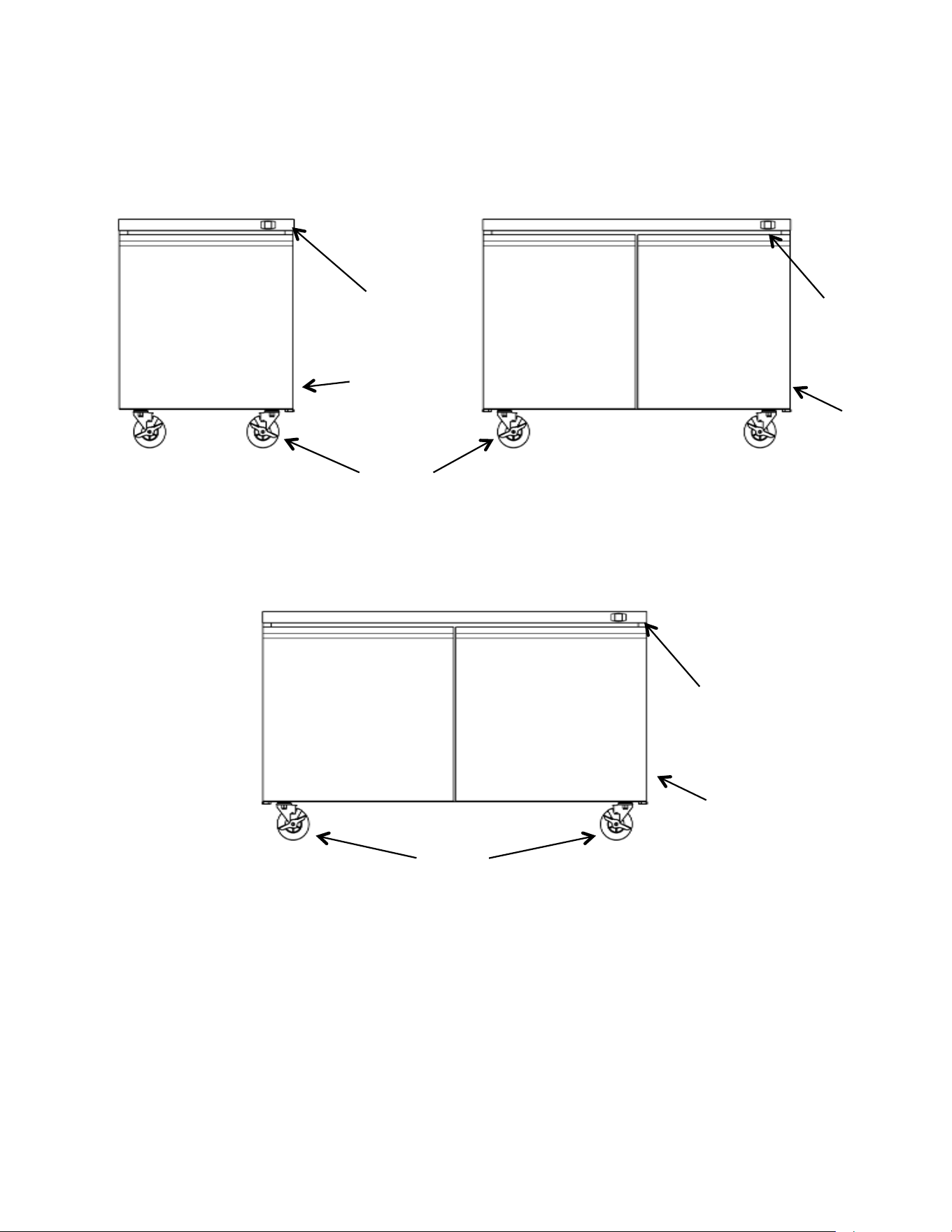
COMPONENT INFORMATION
MVF48UHC/MVR48UHC
MVF29UHC/ MVR29UHC
THERMOSTAT
CONTROL
PANEL
POWER SWITCH
AND
CORD LOCATED
ON UNIT REAR
THERMOSTAT
CONTROL PANEL
REFRIGERATOR
SOLID DOOR
CASTERS
MVF60UHC/MVR60UHC
REFRIGERATOR
SOLID DOORS
REFRIGERATOR
SOLID DOORS
CASTERS
POWER
SWITCH
AND CORD
LOCATED
ON UNIT
REAR
POWER SWITCH AND
CORD LOCATED ON
UNIT REAR
THERMOSTAT
CONTROL PANEL

APPLIANCE INSTALLATION
Remove Packaging Materials
IMPORTANT:
Do not remove any permanent instruction labels or the data label on your appliance.
• Remove tape and glue from your appliance before using.
• To remove any remaining tape or glue, rub the area briskly with your thumb. Tape or glue residue can also be
easily removed by rubbing a small amount of liquid dish soap over the adhesive with your fing
ers. Wipe with
warm water and dry with a soft cloth.
• Do not use sharp instruments, rubbing alcohol, flammable fluids, or abrasive cleaners to remove tape or glue.
These products can damage the surface of your appliance.
NOTICE:
LOSS OR SPOILAGE OF PRODUCTS IN YOUR APPLIANCE IS NOT COVERED BY WARRANTY. IN ADDITION TO
FOLLOWING RECOMMENDED INSTALLATION PROCEDURES. PLEASE RUN THE APPLIANCE 24 HOURS PRIOR
TO USAGE.
Location Requirements
• Appliances represented in this manual are intended for indoor use only.
• Be sure the location chosen has a floor strong enough to support the total weight of the cabinet and contents as a fully
loaded unit can weigh as much as 800 pounds.
• Reinforce the floor as necessary to provide for maximum loading.
• For the most efficient refrigeration, be sure to provide good air circulation inside and out.
Inside cabinet:
Do not pack the units so full that air cannot circulate. The refrigerated air is discharged at the top rear of the unit. It is
important to allow for proper air flow from the top rear to the bottom of the unit. Obstructions to this air flow can cause
evaporator coil freeze ups and loss of temperature or overflow of water from the evaporator drain pan. The shelves have a
rear turn up on them to prevent this. However, bags and other items can still be located to the far rear of the cabinet. Air is
brought into the evaporator coil with fans mounted to the front of the coil.
Outside cabinet:
Be sure that the unit has access to ample air. Avoid hot corners and locations near stoves and ovens.
It is recommended that the unit be installed no closer than 2" (51mm) from any wall and a max door swing clearance of
60.5 in. (1537mm).
Page 11 of 19
WARNING
Excessive Weight Hazard
Use two or more persons to move and install appliances.
Failure to do so may result in back or other injury.
Page 12 of 19
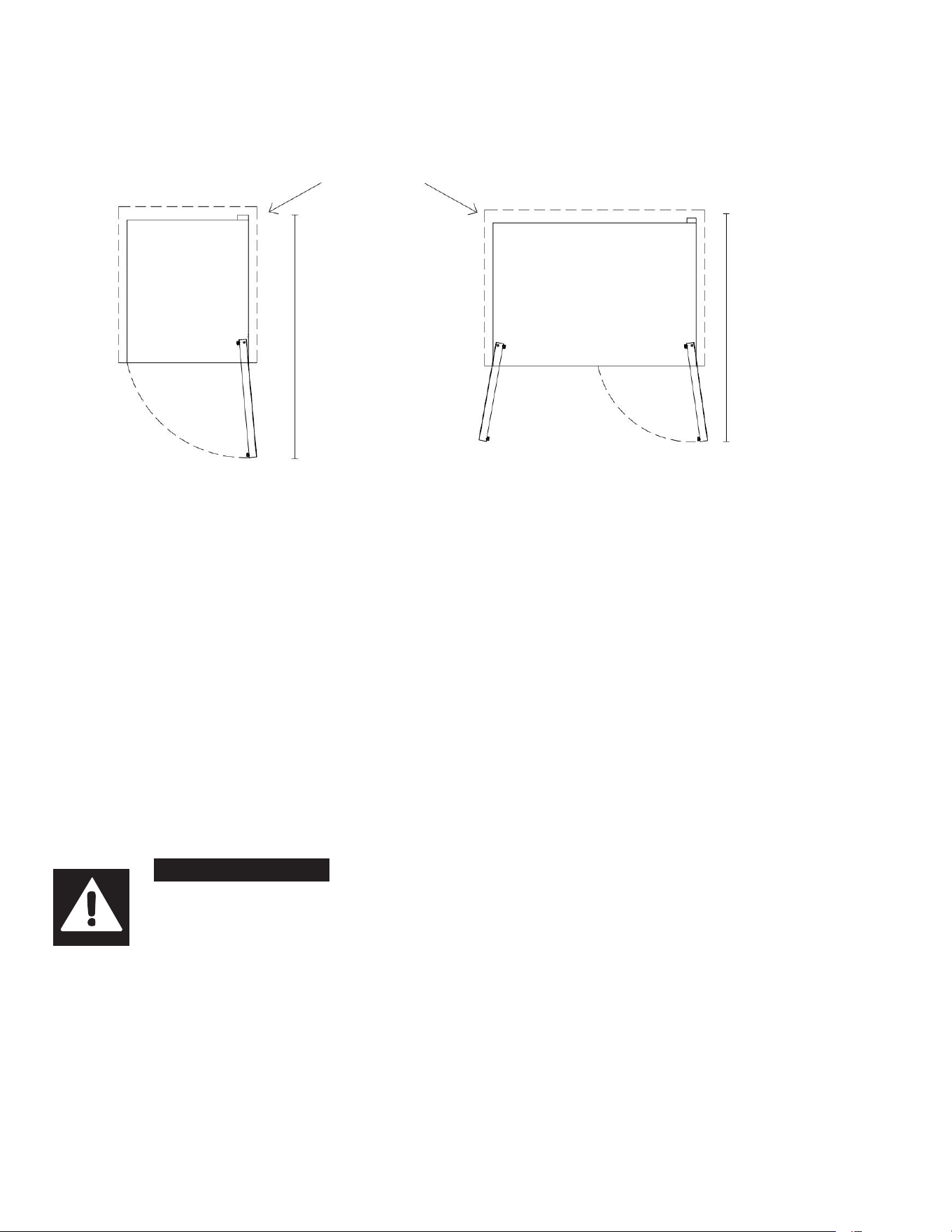
APPLIANCE INSTALLATION (cont.)
Installation Clearance
Leveling
Ensure the floor where the unit is to be located is level or shim the unit to level it.
Stabilizing
All models are supplied with casters for your convenience. It is very important, however, that the cabinet be installed in a
stable condition with the front wheels locked while in use. Should it become necessary to lay the unit on its side or back for
any reason, allow at least 24 hours before start-up to allow compressor oil to flow back into place. Failure to meet this
requirement can cause compressor failure and unit damage, which would not be covered by your warranty.
NOTICE:
Unit repairs will not be subject to standard unit warranties if due to improper installation procedures.
Electrical Connection
Refer to the amperage data on the Technical Information table, the serial tag, your local code or the National Electrical Code to
be sure that unit is connected to the proper power source.
DANGER
The unit must be turned OFF and disconnected from the power source whenever
performing service, maintenance functions or cleaning the refrigerated area. Failure to
comply may result in Death or Severe Personnel Injury.
MVF48UHC/ MVR48UHC/ MVF60UHC/MVR60UHC
MVF29UHC/MVR29UHC
2”
51mm
M
V
F29UHC/MVR29UHC
57.8 in
1467.5 mm
Max Door Swing
Clearance
MVF48UHC/ MVR48UHC
53.2 in
1352.5 mm
Max Door Swing
Clearance
MVF60UHC/MVR60UHC
59.6 in
1514.5 mm
Max Door Swing
Clearance
Page 13 of 19
OPERATION
Refrigerated cycle
1.
Every 6 hours, the unit will turn off and to allow the evaporator coil to air defrost. The controller now displays defrost
symbol. When the coil temperature reaches 53°F (12°C) or after 30 minutes of defrost, the unit will turn on again.
2.
Anti-condensation heaters on door frames work in conjunction with the compressor.
3.
Recommended holding temperature range: 34° to 40°F (2° to 5°C).
4.
Comes factory set to 39°F (4°C).
Power Switch:
The power switch is located on the front of the bottom panel. When the unit is on, the switch will glow green.
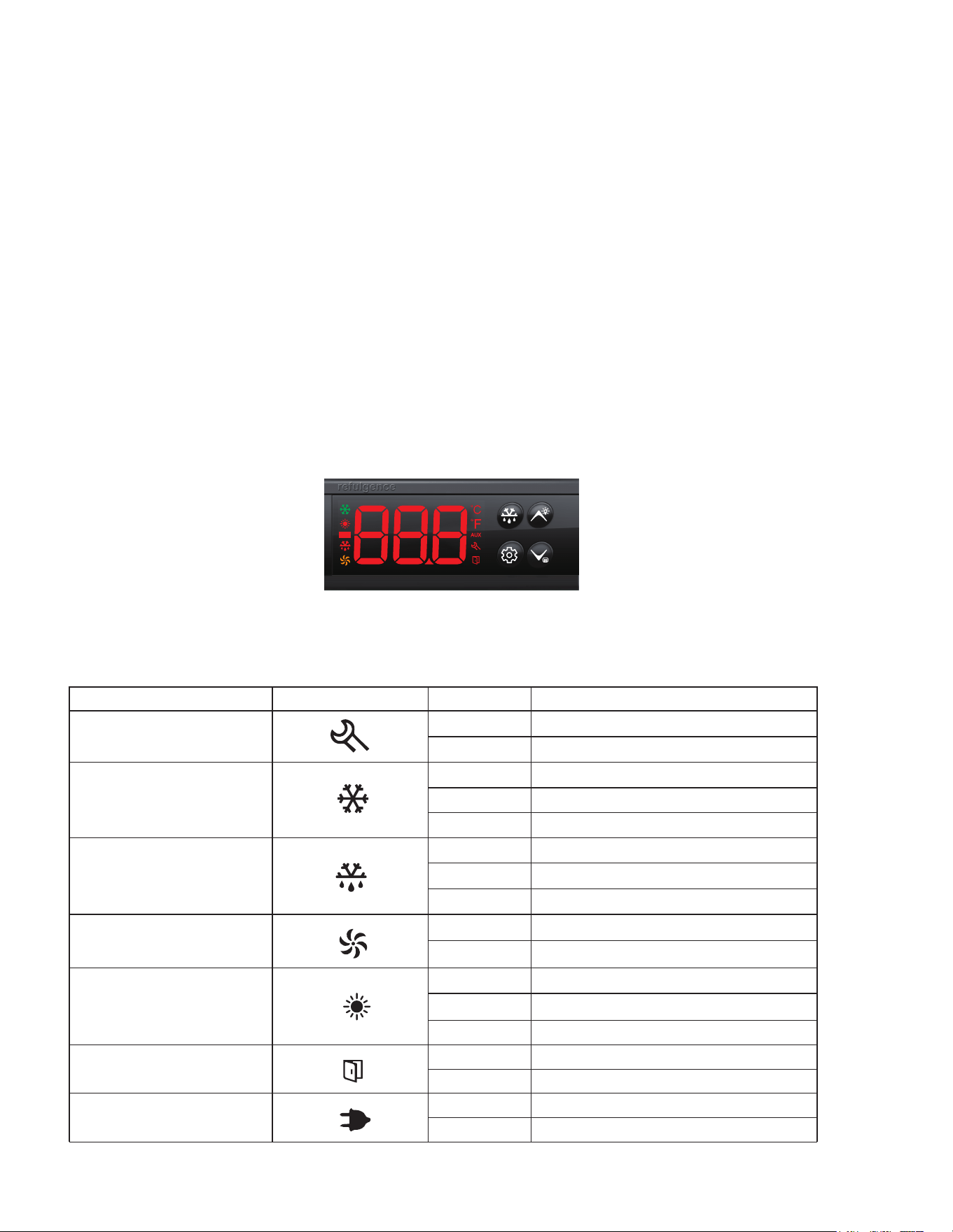
SOLID-STATE THERMOSTAT DESCRIPTIONS
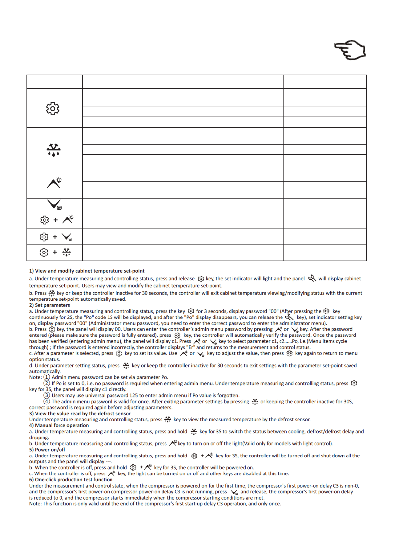
1. FRONT PANEL COMMANDS
Moun�ng size: 71 * 29mm Product size: 78.5* 34.5 * 74mm
2.3 Specifica�on size
2.4 Indicator symbol and status descrip�on
Indicator light Symbol
Status
Meaning
Refrigeration
Defrost
Fan
Door switch
Setting
Heating indicator
Power
ON
OFF
FLASH
ON
OFF
FLASH
ON
OFF
FLASH
ON
OFF
ON
OFF
ON
OFF
ON
OFF
Parameter setting
Status of temperature measuring and controlling
Refrigeration work
Refrigeration stop
Refrigeration time delay
Defrost work
Defrost stop
Fan work
Fan stop
Cabinet door open
Cabinet door close
Defrost delay/defrost drip
Heating work
Heating stop
Heating delay
External power supply
AC power supply
Page 14 of 19
OPERATION
2. MAIN FUNCTIONS
SET
Keys
Function
Button action
Switch between menu and parameter
Pressing the keys for 3s
Press the response
Press the response
Press the response
Press the response
The real-time display interface is continuously pressed to enter the parameter setting state
View and modify the cabinet temperature setting
The real-time display interface continuously switches between refrigeration, defrost/defrost delay, and
defrost drip for 3 seconds
The real-time display interface is pressed to view the temperature value of the evaporator sensor
Press the parameter setting interface to exit the parameter setting state
Press the parameter setting interface to adjust the menu and parameters
Live display interface pressed to turn lights on/off (only valid for models with light control)
Press the parameter setting interface to adjust the menu and parameters
Controller on/off
View the interface and press and hold 3S to enter maintenance mode
Force start refrigeration
Pressing the keys for 3s
Press the response
Press the response
Press the response
Combine the keys and press 3S
continuously
Combine the keys and press 3S
continuously
Combine the keys and press 3S
continuously
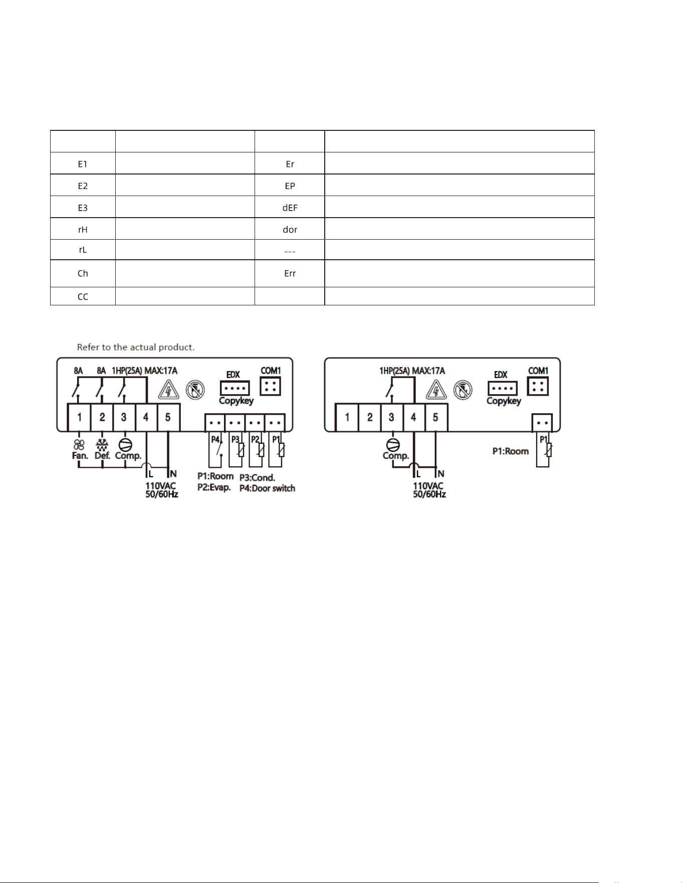
Prompt code
Code explana�on
Cabinet temperature sensor failure
Evaporator sensor failure
Condenser sensor failure
Cabinet high temperature alarm
Cabinet low temperature alarm
Condenser high temperature alarm
Condenser cleaning reminder
Copy card programming failure/password input error
I nconsistent data between copy card and controller, programming failure
Defros�ng
The door opens on cue
The controller press the power key to turn off the display code
Parameter error, press any key to eliminate and restore the default parameters
Code explana�onPrompt code
3. ALARM SIGNALLING
Page 15 of 19

Page 16 of 19
CLEANING AND MAINTENANCE
DANGER
The unit must be turned off and disconnected from the power source whenever performing
service, maintenance functions or cleaning the refrigerated area. Failure to comply may
result in death or severe personnel injury.
Exterior and Interior Cleaning of Appliances
Clean using soap and warm water. If this isn't sufficient, try ammonia and water or a nonabrasive liquid cleaner. When cleaning
the exterior, always rub with the "grain" of the stainless steel to avoid marring the finish.
• Do not use an abrasive cleaner because it will scratch the stainless steel and plastic and can damage the breaker strips and
gaskets.
Cleaning the Condenser Coil
Regular cleaning is recommended every 90 days. In some instances, you may find that there is a large amount of debris and
dust or grease accumulated prior to the 90 day time frame. In these cases the condenser coil should be cleaned every 30
days.
If the buildup on the coil consists of only light dust and debris, the condenser coil can be cleaned with a simple brush. Heavier
dust build-up may require a vacuum or even compressed air to blow through the condenser coil.
If heavy grease is present, there are de-greasing agents available for refrigeration use and specifically for the condenser coils.
The condenser coil may require cleaning with the de-greasing agent and then blown through with compressed air.
Failure to maintain a clean condenser coil can initially cause high temperatures and excessive run times. Continuous operation
with dirty or clogged condenser coils can result in compressor failures. Neglecting the condenser coil cleaning procedures will
void any warranties associated with the compressor or cost to replace the compressor.
• For efficient operation, keep the condenser surface free of dust, dirt, and lint.
• We recommend cleaning the condenser coil at least once per month.
• Clean the condenser with a commercial condenser coil cleaner and a soft brush, available from any commercial
refrigeration equipment retailer, or vacuuming the condenser with a shop vac or use CO
2
.
CAUTION
Never use a high pressure water wash for this cleaning procedure as water can damage
the electrical components located near or at the condenser coil.
In order to maintain proper refrigeration performance, the condenser fins must be cleaned of dust, dirt and grease regularly.
It is recommended that this be done at least every three months. If conditions are such that the condenser is totally blocked
in three months, the frequency of cleaning should be increased. Clean the condenser with a vacuum cleaner or stiff brush.
If extremely dirty, a commercial-grade condenser cleaner may be required.
Page 17 of 19
CLEANING AND MAINTENANCE (cont.)
Stainless Steel Care and Cleaning
To prevent rust or discoloration on stainless steel several important steps need to be taken. First, we need to understand
the properties of stainless steel. Stainless steel contains 70-80% iron which will rust. It also contains 12-20% chromium
which forms an invisible passive film over the steels surface which acts as a shield against corrosion. As long as the
protective layer is intact, the metal still resist oxidation. If the film is broken or contaminated, outside elements can begin to
breakdown the steel and begin to form rust or discoloration.
CAUTION
Proper cleaning of stainless steel requires soft cloths or plastic scouring pads, never use
steel pads, wire brushes or scrapers!
Cleaning solutions need to be alkaline based or non-chloride based. Any cleaner containing chlorides will damage the
protective film of the stainless steel. If cleaners containing chlorides are used, be sure to rinse and dry thoroughly.
Routine cleaning of stainless steel can be done with soap and water. Extreme stains or grease should be cleaned with a
non-abrasive cleaner and plastic scrub pad. It is always good to rub with the grain of the steel. There are also stainless
steel cleaners available which can restore and preserve the finish of the steel’s protective layer.
Early signs of stainless steel breakdown can consist of small pits and cracks. If this has begun, clean thoroughly and start
to apply stainless steel cleaners in attempt to restore the passivity of the steel.
CAUTION
Never use an acid based cleaning solution! Many food products have an acidic content
which can deteriorate the finish. Be sure to clean the stainless steel surfaces of all food
products.
Gasket Maintenance
Gaskets require regular cleaning to prevent mold and mildew build up and also to keep the elasticity of the gasket. Gasket
cleaning can be done with the use of warm soapy water. Avoid full strength cleaning products on gaskets. Do not use
sharp tools or knives to scrape or clean the gasket.
Gaskets can easily be replaced and don’t require the use of tools or authorized service technicians. The gaskets are "Dart"
style and can be pulled out of the grove in the door and replaced by pressing the new one back into place.
Doors/Hinges
If the door is beginning to sag, tighten the screws that mount the hinge brackets to the frame of the unit. If the doors are
loose or sagging, this can cause the hinge to pull out of the frame which may damage both doors and door hinges.
Drain Maintenance
Each unit has a drain located inside the unit which removes the condensation from the evaporator coil and evaporates it into
an external condensate evaporator pan. The drain can become loose or disconnected. If you notice excessive water
accumulation on the inside of the unit, be sure the drain tube is connected from the evaporator housing to the condensate
evaporator drain pan.
If water starts to collect underneath the unit, check the condensate evaporator drain tube to be sure it is still located inside the
drain pan.
If your floor is not level, this can also cause drain problems. Be sure all drain lines are free of obstructions because this may
cause water to back up and overflow the drain pans.
Page 18 of 19
TROUBLESHOOTING GUIDE
BEFORE CALLING FOR SERVICE
If the unit appears to be malfunctioning, read through the OPERATION section of this manual first. If the problem
persists, see Troubleshooting below. The problem may be something very simple that can be solved without a service
call.
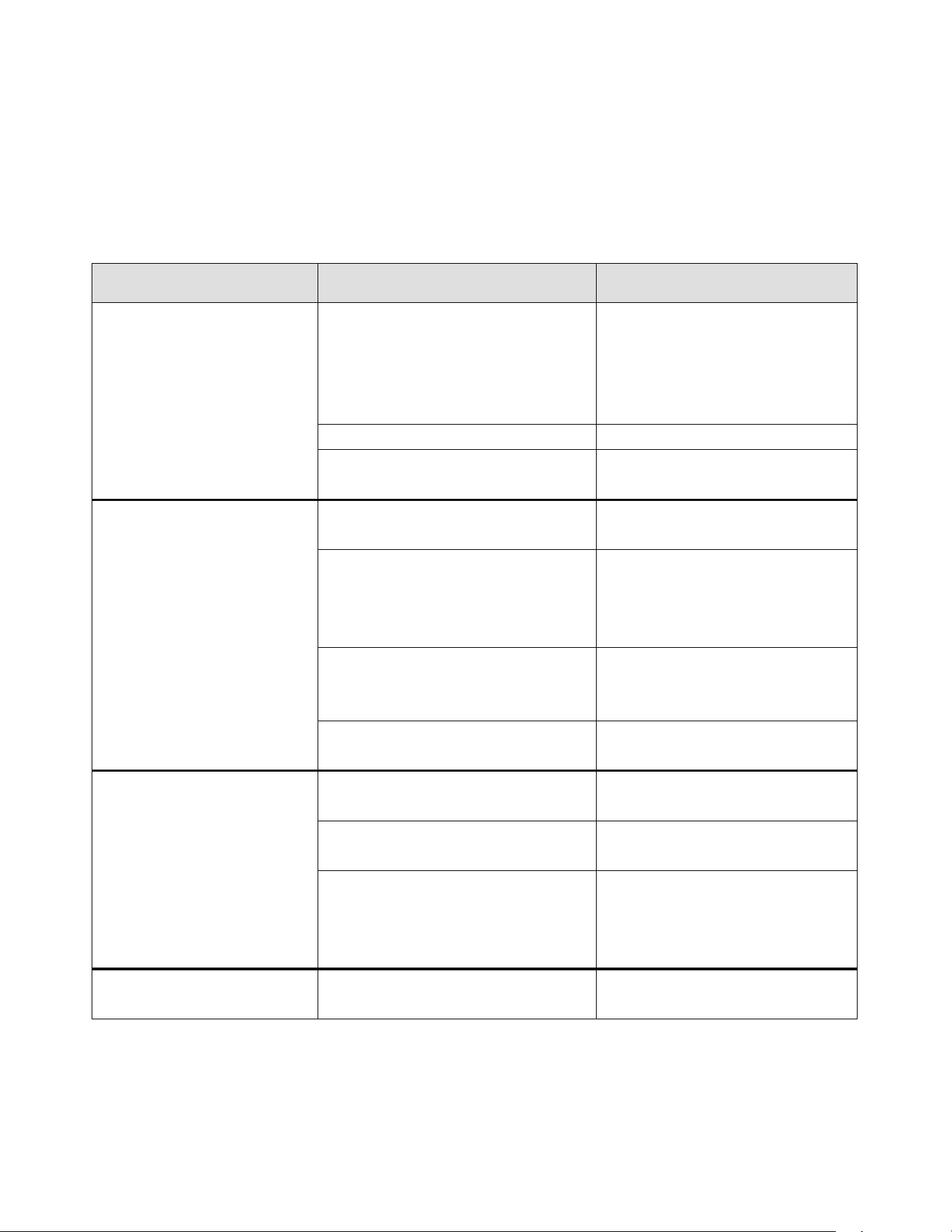
TROUBLESHOOTING
Fault
Probable Cause
Action
Compressor is Not Running
Fuse blown or circuit breaker tripped
Replace fuse or reset circuit
breaker. If replacement of fuse or
reset of circuit breaker doesn’t
correct the problem contact a
qualified service technician.
Power cord unplugged
Plug in power cord
Thermostat set too high
Set thermostat to lower
temperature
Cabinet Temperature is too
Warm
Thermostat is set too high
Set thermostat to lower
temperature.
Airflow is blocked
Re-arrange products to allow for
proper air flow. Make sure there is
at least four inches of clearance
from the fan
Low refrigerant levels
Contact a qualified service
technician to check refrigerant
levels
Door is slightly ajar
Make sure door is completely
closed.
Interior Light is Not Working
Poor switch connection
Turn off light switch and turn it back
on.
Bulb is not connected
Make sure the bulb is correctly
inserted in the socket.
Bulb has burned out
Replace the bulb. If replacement of
bulb doesn’t correct the problem
contact a qualified service
technician.
Condensation is Collecting on
the Cabinet and/or Floor
Gasket is not sealing properly
Clean, repair, or replace the gasket
as necessary
Page 19 of 19
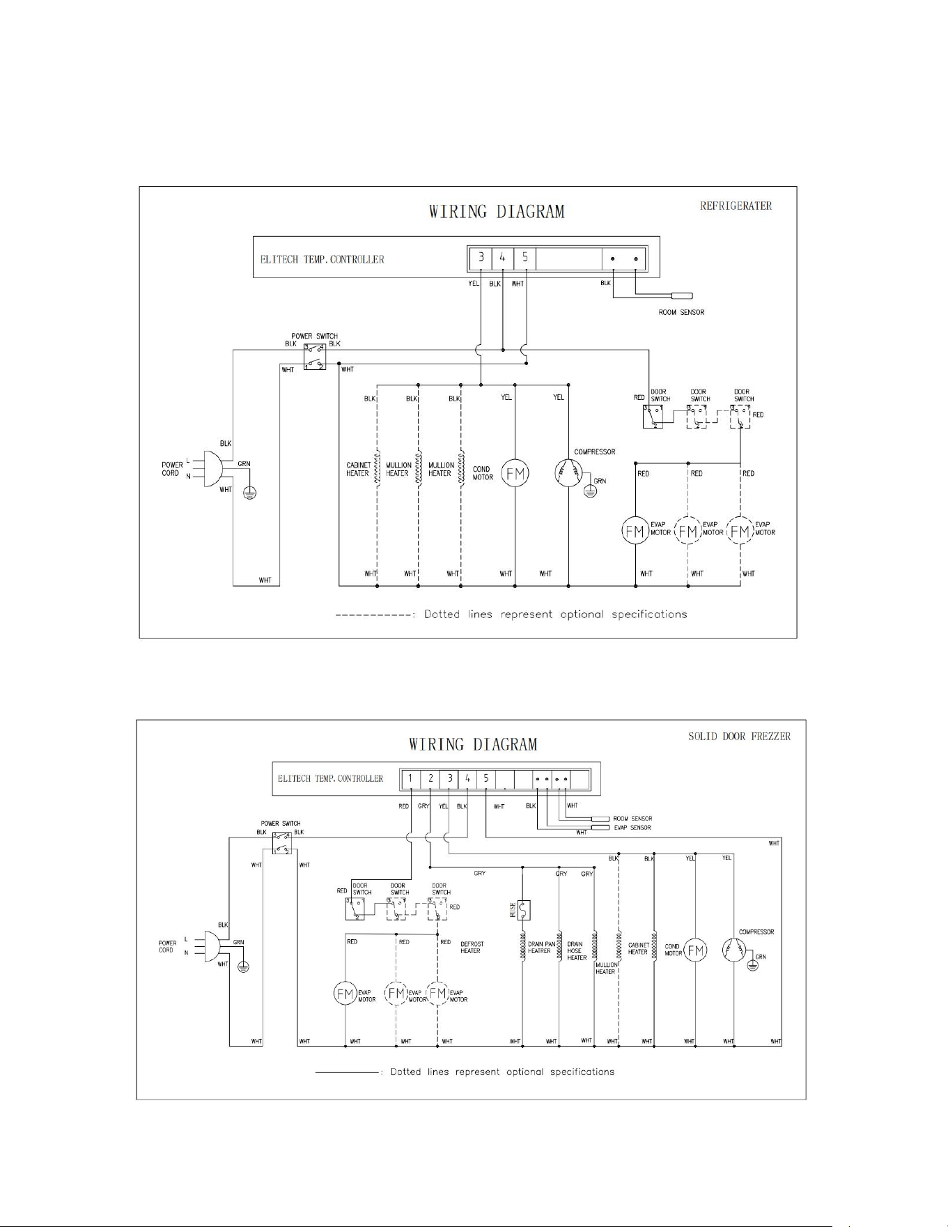
WIRING DIAGRAMS
MODEL: MVR29UHC /MVR48UHC/MVR60UHC
MODEL: MVF29UHC /MVF48UHC/MVF60UHC
