User Manual
WWH22CWA
WWH39CWA
WWH22HWA
WWH39HWA
WWH27CWA
WWH52HWA
WWH27HWA
WWH60HWA
2 Contents
Congratulations and thank you for choosing our Electric
your new air conditioner a pleasure to use. Before you use
the air conditioner, we recommend that you read through
the entire user manual, which provides the description of
the air conditioner and its functions.
To avoid the risks that are always present when you use an
electrical appliance, it is important that the air conditioner
is installed correctly and that you read the safety instructions
carefully to avoid misuse and hazards.
We recommend that you keep this instruction booklet
for
future reference and pass it on to any future owners.
After unpacking the air conditioner please check it is not
damaged. If in doubt, do not use the air conditioner but
contact your local Electrolux Customer Care Centre.
Information on disposal for users
Most of the packing materials are recyclable.
Please dispose of those materials through your local
recycling depot or by placing them in appropriate
collection containers.
If you wish to discard this air conditioner, please contact
your local authorities and ask for the correct method
of disposal.
This product contains refrigerant which must be
reclaimed by a licensed refrigeration mechanic before the
product can be disposed of.
REFRIGERANT WARNING
This unit uses refrigerant R32 and must be disposed of
by a licensed refrigeration mechanic with knowledge of
appropriate gas reclamation methods.
The air conditioner is not intended for use by young
children or i
rmed persons without supervision.
Young children should be supervised to ensure that they
do not play with the air conditioner.
Contact an authorised installer for installation of this unit.
Contact an authorised service technician for repair or
maintenance of this unit.
If the power cord is to be replaced, replacement work
must be performed by authorised personnel only.
Installation work must be performed in accordance
with the national wiring Standards by authorised
personnel only.
Safety precautions ..................................................................... 3
Prior to operation.............................................................. 4
Unit parts identi
cation ............................................................ 5
Operating instructions ..............................................................5
Maintenance ...................................................................... 9
Installation instructions ..........................................................10
Troubleshooting .......................................................................12
Conditions of use
This appliance is designed and intended to be used in normal
domestic applications only.
Congratulations Contents
Important information that may
impact your Manufacturer’s Warranty
Adherence to the directions for use in this manual is
extremely important for health and safety. Failure to
strictly adhere to the requirements in this manual may
result in personal injury, property damage and affect
your ability to make a claim under the Westinghouse
manufacturer’s warranty provided with your product.
Products must be used, installed and operated in
accordance with this manual. You may not be able to
claim on the Westinghouse manufacture
r’s warranty in the
event that your product fault is due to failure to adhere
this manual.
Westinghouse Air Conditioning
ENVIRONMENTAL TIP
CAUTION
Do not use means to accelerate the defrosting
process or to clean, other than those recommended
by the manufacturer.
Do not store the appliance in a room with continuously
operating ignition sources (for example open flames,
an operating electric heater or an operating gas
appliance with a continuously lit pilot flame).
Do not pierce or burn.
Be aware that the refrigerant may be odourless.
Connect with power properly.
Otherwise, it may cause electric shock or fire due to
excess heat generation.
Do not operate or stop the unit by switching on or
off the power.
It may cause electric shock or fire due to heat generation.
Do not damage or use an unspecified power cord.
It may cause electric shock or fire.
If the power cord is damaged, it must be replaced by
the manufacturer or an authorised service centre or a
similarly qualified person in order to avoid a hazard.
Do not modify power cord length or share the outlet
with other appliances.
It may cause electric shock or fire due to heat generation.
Do not operate with wet hands or in damp environment.
It may cause electric shock.
Do not direct airflow at room occupants only.
This could damage your health.
Always ensure effective earthing.
No earthing may cause electric shock.
Do not allow water to run into electric parts.
It may cause failure of machine or electric shock.
Always install circuit breaker and a dedicated
power circuit.
No installation may cause fire and electric shock.
Disconnect the power if strange sounds, smell,
or smoke comes from the unit.
It may cause fire and electric shock.
Do not use the socket if it is loose or damaged.
It may cause fire and electric shock.
Do not open the unit during operation.
It may cause electric shock.
Keep firearms away.
It may cause a fire.
Do not use the power cord close to heating appliances.
It may cause fire and electric shock.
Do not use the power cord near flammable gas or
combustibles, such as gasoline, benzene, thinner, etc.
It may cause an explosion or fire.
Ventilate room before operating air conditioner if
there is a gas leakage from another appliance.
It may cause explosion, fire and burns.
Do not disassemble or modify unit.
It may cause failure and electric shock.
Important Safety Instructions
Important safety instructions 3
• Contact an authorised service technician for repair or
maintenance of this unit.
• Contact a licensed installer for installation of this unit.
• The air conditioner is not intended for use by young
children or infirmed persons without supervision.
• Young children should be supervised to ensure that they
do not play with the air conditioner.
• This air conditioner must
be installed in accordance with
AS/NZS 3000:2000 and your electricity suppliers rules.
• There are local council rules regarding maximum
allowable noise levels emitted by air conditioners.
• If the power cord is to be replaced, replacement work
shall be performed by authorised personnel only.
• Installation work must be performed in accordance with
the national wiring standards by authorised personnel
only. Wrong connection can cause overheating or fire.
Inside this manual you will fi
nd many helpful hints on how to
use and maintain your air conditioner properly.
Just a little preventative care on your part can save you
a great deal of time and money over the life of your air
conditioner. You'll find many answers to common problems
in the chart of troubleshooting tips. If you review the chart of
Troubleshooting Tips first, you may not need to call for service.
Meanings of symbols used in this manual are shown below:
This symbol indicates inf
ormation concerning your
personal safety
This symbol indicates information on how to avoid
damaging the appliance
This symbol indicates tips and information about
use of the appliance
This symbol indicates tips and information about
economical and ecological use of the appliance
This symbol indicates never to do this
This symbol indicates always do this
Westinghouse Air Conditioning
CAUTION
CAUTION
WARNING
ENVIRONMENTAL TIP
TIPS AND INFORMATION
WARNING
When the air filter is to be removed, do not touch the
metal parts of the unit.
It may cause an injury.
Do not clean the air conditioner with water.
Water may enter the unit and degrade the insulation.
It may cause an electric shock.
Ventilate the room well when used together with
a stove, etc.
An oxygen shortage may occur.
Do not put a pet or house plant where it will be
exposed to direct air flow.
This could injure the pet or plant.
Do not use for special purposes.
Do not use this air conditioner to preserve precision
devices, food, pets, plants, and art objects. It may
cause deterioration of quality, etc.
Stop operation and close the window in storm
or hurricane.
Operation with windows opened may cause wetting of
indoor and soaking of household furniture.
Hold the plug by the head of the power plug when
taking it out.
It may cause electric shock and damage.
Turn off the main power switch when not using
the unit for a long time.
It may cause failure of product or fire.
Do not place obstacles around air-inlets or inside
of air-outlet.
It may cause failure of appliance or accident.
Ensure that the installation bracket of the appliance is
not damaged due to prolonged exposure.
If bracket is damaged, there is concern of damage due
to falling of unit.
Always insert the filters securely. Clean filter once
every two weeks.
Operation without filters may cause failure.
Do not use strong detergent such as wax or
thinner but use a soft cloth.
Appearance may be deteriorated due to change
of product colour or scratching of its surface.
Do not place heavy object on the power cord and
ensure that the cord is not compressed.
There is danger of fire or electric shock.
If water enters the unit, turn the unit off and
disconnect the power, contact a qualified
service technician.
Use caution when unpacking and installing.
Sharp edges could cause injury.
Do not drink water drained from air conditioner.
It contains contaminants and could make you sick.
Westinghouse Air Conditioning4 important safety instructions
CAUTION The Refrigerant
extinguishing equipment shall be available to hand. Have a
dry powder or CO2 re extinguisher adjacent to the charging
area.
No ignition sources
No person carrying out work in relation to a refrigerating
system which involves exposing any pipe work shall use any
sources of ignition in such a manner that it may lead to the
risk of re or explosion. All possible ignition sources,
including cigarette smoking, should be kept sufciently far
away from the site of installation, repairing, removing and
disposal, during which refrigerant can possibly be released
to the surrounding space. Prior to work taking place, the area
around the equipment is to be surveyed to make sure that
there are no ammable hazards or ignition risks. "No
Smoking" signs shall be displayed.
Ventilated area
Ensure that the area is in the open or that it is adequately
ventilated before breaking into the system or conducting any
hot work. A degree of ventilation shall continue during the
period that the work is carried out. The ventilation should
safely disperse any released refrigerant and preferably expel
it externally into the atmosphere.
Checks to the refrigerating equipment
Where electrical components are being changed, they shall
be t for the purpose and to the correct specication. At all
times the manufacturer's maintenance and service guidelines
shall be followed. If in doubt, consult the manufacturer’ s
technical department for assistance.
The following checks shall be applied to installations using
ammable refrigerants:
– the actual refrigerant charge is in accordance with the room
size within which the refrigerant containing parts are installed;
– the ventilation machinery and outlets are operating
adequately and are not obstructed;
– if an indirect refrigerating circuit is being used, the
secondary circuit shall be checked for the presence of
refrigerant;
– marking to the equipment continues to be visible and
legible. Markings and signs that are illegible shall be
corrected;
– refrigerating pipe or components are installed in a position
where they are unlikely to be exposed to any substance which
may corrode refrigerant containing components, unless the
components are constructed of materials which are inherently
resistant to being corroded or are suitably protected against
being so corroded.
Checks to electrical devices
Repair and maintenance to electrical components shall
include initial safety checks and component inspection
procedures. If a fault exists that could compromise safety,
then no electrical supply shall be connected to the circuit
until it is satisfactorily dealt with. If the fault cannot be
corrected immediately but it is necessary to continue
operation, an adequate temporary solution shall be used.
This shall be reported to the owner of the equipment so all
parties are advised.
Initial safety checks shall include:
– that capacitors are discharged: this shall be done in a safe
manner to avoid possibility of sparking;
– that no live electrical components and wiring are exposed
while charging, recovering or purging the system;
– that there is continuity of earth bonding.
Repairs to sealed components
During repairs to sealed components, all electrical supplies
shall be disconnected from the equipment being worked
upon prior to any removal of sealed covers, etc. If it is
absolutely necessary to have an electrical supply to
equipment during servicing, then a permanently operating
form of leak detection shall be located at the most critical
point to warn of a potentially hazardous situation.
Particular attention shall be paid to the following to ensure
that by working on electrical components, the casing is not
altered in such a way that the level of protection is affected.
This shall include damage to cables, excessive number of
connections, terminals not made to original specication,
damage to seals, incorrect tting of glands, etc.
– Ensure that the apparatus is mounted securely.
– Ensure that seals or sealing materials have not degraded to
the point that tlonger serve the purpose of preventing the
ingress of ammable atmospheres.
Replacement parts shall be in accordance with the
manufacturer’s specications.
NOTE: The use of silicon sealant can inhibit the effectiveness
of some types of leak detection equipment. Intrinsically safe
components do not have to be isolated prior to working on
them.
Repair to intrinsically safe components
Do not apply any permanent inductive or capacitance loads
to the circuit without ensuring that this will not exceed the
permissible voltage and current permitted for the equipment
in use.
Intrinsically safe components are the only types that can be
worked on while live in the presence of a ammable
atmosphere. The test apparatus shall be at the correct rating.
Replace components only with parts specied by the
manufacturer. Other parts may result in the ignition of
refrigerant in the atmosphere from a leak.
Cabling
Check that cabling will not be subject to wear, corrosion,
excessive pressure, vibration, sharp edges or any other
adverse environmental effects. The check shall also take into
account the effects of aging or continual vibration from
sources such as compressors or fans.
Leak detection methods
Leak detection uids are suitable for use with most
refrigerants but the use of detergents containing chlorine
shall be avoided as the chlorine may react with the refrigerant
and corrode the copper pipe-work.
Detection of ammable refrigerants
Under no circumstances shall potential sources of ignition be
used in the searching for or detection of refrigerant leaks. A
halide torch (or any other detector using a naked ame) shall
not be used.
The following leak detection methods are deemed
acceptable for all refrigerant systems.
Electronic leak detectors may be used to detect refrigerant
leaks but, in the case of ammable refrigerants, the sensitivity
may not be adequate, or may need re-calibration.( Detection
equipment shall be calibrated in a refrigerant-free area.)
Ensure that the detector is not a potential source of ignition
and is suitable for the refrigerant used. Leak detection
equipment shall be set at a percentage of the LFL of the
refrigerant and shall be calibrated to the refrigerant
employed, and the appropriate percentage of gas (25%
maximum) is conrmed.
Leak detection uids are also suitable for use with most
refrigerants but the use of detergents containing chlorine
shall be avoided as the chlorine may react with the refrigerant
and corrode the copper pipe-work.
NOTE: Examples of leak detection uids are
– bubble method,
– uorescent method agents.
If a leak is suspected, all naked ames shall be removed /
extinguished.
If a leakage of refrigerant is found which requires brazing, all
of the refrigerant shall be recovered from the system, or
isolated (by means of shut off valves) in a part of the system
remote from the leak. Removal of refrigerant shall be
according to Clause Removal and evacuation.
Removal and evacuation
When breaking into the refrigerant circuit to make repairs - or
for any other purpose - conventional procedures shall be
used. However, for ammable refrigerants it is important that
best practice is followed since ammability is a consideration.
The following procedure shall be adhered to:
• remove refrigerant;
• purge the circuit with inert gas (optional for A2L);
• evacuate (optional for A2L);
• purge with inert gas (optional for A2L);
• open the circuit by cutting or brazing.
The refrigerant charge shall be recovered into the correct
recovery cylinders. For appliances containing ammable
refrigerants other than A2L refrigerants, the system shall be
purged with oxygen-free nitrogen to render the appliance
safe for ammable refrigerants. This process may need to be
repeated several times. Compressed air or oxygen shall not
be used for purging refrigerant systems.
For appliances containing ammable refrigerants, other than
A2L refrigerants, refrigerants purging shall be achieved by
breaking the vacuum in the system with oxygen-free nitrogen
and continuing to ll until the working pressure is achieved,
then venting to atmosphere, and nally pulling down to a
vacuum. This process shall be repeated until no refrigerant is
within the system. When the nal oxygen-free nitrogen
charge is used, the system shall be vented down to
atmospheric pressure to enable work to take place. This
operation is absolutely vital if brazing operations on the
pipe-work are to take place.
Ensure that the outlet for the vacuum pump is not close to
any potential ignition sources and that ventilation is available.
Charging procedures
In additon to conventional charging procedures, the
following requirements shall be followed.
• Ensure that contamination of different refrigerants does not
occur when using charging equipment. Hoses or lines shall
be as short as possible to minimise the amount of refrigerant
contained in them.
•Cylinders shall be kept in an appropriate position according
to the instructions.
•Ensure that the refrigerating system is earthed prior to
charging the system with refrigerant.
•Label the system when charging is complete (if not already).
•Extreme care shall be taken not to overll the refrigerating
system.
Prior to recharging the system, it shall be pressure-tested
with the appropriate purging gas. The system shall be
leak-tested on completion of charging but prior to
commissioning.
A follow up leak test shall be carried out prior to leaving the site.
Decommissioning
Before carrying out this procedure, it is essential that the
technician is completely familiar with the equipment and all its
detail. It is recommended good practice that all refrigerants are
recovered safely. Prior to the task being carried out, an oil and
refrigerant sample shall be taken in case analysis is required prior
to reuse of reclaimed refrigerant. It is essential that electrical
power is available before the task is commenced.
a). Become familiar with the equipment and its operation.
b). Isolate system electrically.
c). Before attempting the procedure, ensure that:
– mechanical handling equipment is available, if required, for
handling refrigerant cylinders;
– all personal protective equipment is available and being used
correctly;
– the recovery process is supervised at all times by a competent
person;
– recovery equipment and cylinders conform to the appropriate
standards.
d). Pump down refrigerant system, if possible.
e). If a vacuum is not possible, make a manifold so that
refrigerant can be removed from various parts of the system.
f ). Make sure that cylinder is situated on the scales before
recovery takes place.
g). Start the recovery machine and operate in accordance with
manufacturer's instructions.
h). Do not overll cylinders. (No more than 80% volume liquid
charge).
i ). Do not exceed the maximum working pressure of the cylinder,
even temporarily.
j ). When the cylinders have been lled correctly and the process
completed, make sure that the cylinders and the equipment are
removed from site promptly and all isolation valves on the
equipment are closed off.
k). Recovered refrigerant shall not be charged into another
refrigeration system unless it has been cleaned and checked.
Labelling
Equipment shall be labelled stating that it has been
de-commissioned and emptied of refrigerant. The label shall
be dated and signed. For appliances containing ammable
refrigerants, ensure that there are labels on the equipment
stating the equipment contains ammable refrigerant.
Recovery
When removing refrigerant from a system, either for servicing
or decommissioning, it is recommended good practice that
all refrigerants are removed safely.
When transferring refrigerant into cylinders, ensure that only
appropriate refrigerant recovery cylinders are employed.
Ensure that the correct number of cylinders for holding the
total system charge are available. All cylinders to be used are
designated for the recovered refrigerant and labelled for that
refrigerant (i.e. special cylinders for the recovery of
refrigerant). Cylinders shall be complete with pressure-relief
valve and associated shut-off valves in good working order.
Empty recovery cylinders are evacuated and, if possible,
cooled before recovery occurs.
The recovery equipment shall be in good working order with
a set of instructions concerning the equipment that is at hand
and shall be suitable for the recovery of all appropriate
refrigerants including, when applicable, ammable
refrigerants. In addition, a set of calibrated weighing scales
shall be available and in good working order. Hoses shall be
complete with leak-free disconnect couplings and in good
condition. Before using the recovery machine, check that it is
in satisfactory working order, has been properly maintained
and that any associated electrical components are sealed to
prevent ignition in the event of a refrigerant release. Consult
manufacturer if in doubt.
The recovered refrigerant shall be returned to the refrigerant
supplier in the correct recovery cylinder, and the relevant
waste transfer note arranged. Do not mix refrigerants in
recovery units and especially not in cylinders.
If compressors or compressor oils are to be removed, ensure
that they have been evacuated to an acceptable level to
make certain that ammable refrigerant does not remain
within the lubricant. The evacuation process shall be carried
out prior to returning the compressor to the suppliers. Only
electric heating to the compressor body shall be employed to
accelerate this process. When oil is drained from a system, it
shall be carried out safely.
To realize the function of the air conditioner unit, a special
refrigerant circulates in the system. The used refrigerant is the
uorideR32, which is specially cleaned. The refrigerant is
ammable and inodorous. Furthermore, it can lead to
explosion under certain conditions. But the ammability of the
refrigerant is very low. It can be ignited only by re.
Compared to common refrigerants, R32 is a nonpolluting
refrigerant with no harm to the ozonosphere. The inuence
upon the greenhouse effect is also lower. R32 has got very
good thermodynamic features which lead to a really high
energy efciency. The units therefore need a less lling.
Do not use means to accelerate the defrosting process or to
clean, other than those recommended by the
manufacture.Should repair be necessary, contact your nearest
authorized Service Centre.
Any repairs carried out by unqualied personnel may be
dangerous.
The appliance shall be stored in a room without continuously
operating ignition sources. (for example: open ames , an
operating gas appliance or an operating electric heater.)
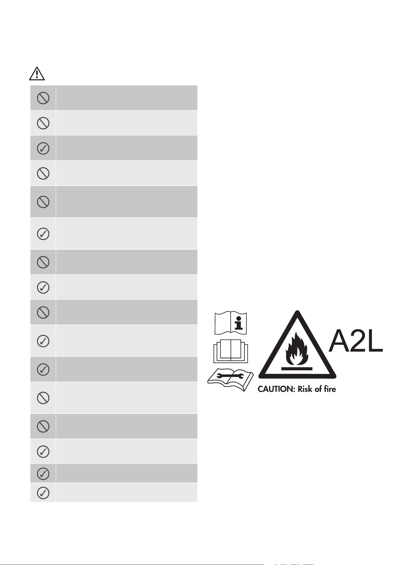
Do not pierce or burn.
Appliance shall be installed, operated and stored in a room
with a oor area larger than 4 m².
Appliance lled with ammable gas R32. For repairs, strictly
follow manufacturer's instructions only.
Be aware that refrigerants may not contain an odour. Read
specialist's manual.
According to EN60335-1
This appliance can be used by children aged from 8 years and
above and persons with reduced physical,sensory or mental
capabilities or lack of experience and knowledge if they have
been given supervision or instruction concerning use of the
appliance in a safe way and understand the hazards involved.
Children shall not play with the appliance.
Cleaning and user maintenance shall not be made by children
without supervision.

The following checks shall be applied to installations
using ammable refrigerants:
– the charge size is in accordance with the room size within
which the refrigerant containing parts are installed;
– the ventilation machinery and outlets are operating
adequately and are not obstructed;
– if an indirect refrigerating circuit is being used, the
secondary circuit shall be checked for the presence of
refrigerant;
– marking to the equipment continues to be visible and
legible. Markings and signs that are illegible shall be
corrected;
– refrigeration pipe or components are installed in a position
where they are unlikely to be exposed to any substance which
may corrode refrigerant containing components, unless the
components are constructed of materials which are inherently
resistant to being corroded or are suitably protected against
being so corroded.
Repair and maintenance to electrical components shall
include initial safety checks and component inspection
procedures. If a fault exists that could compromise
safety, then no electrical supply shall be connected to the
circuit until it is satisfactorily dealt with. If the fault cannot
be corrected immediately but it is necessary to continue
operation, an adequate temporary solution shall be used.
This shall be reported to the owner of the equipment so
all parties are advised.
Initial safety checks shall include:
– that capacitors are discharged: this shall be done in a safe
manner to avoid possibility of sparking;
– that no live electrical components and wiring are exposed
while charging, recovering or purging the system;
– that there is continuity of earth bonding.
Checks to the area
Prior to beginning work on systems containing ammable
refrigerants, safety checks are necessary to ensure that the
risk of ignition is minimised. For repair to the refrigerating
system, DD.4.3 to DD.4.7 shall be completed prior to
conducting work on the system.
Work procedure
Work shall be undertaken under a controlled procedure so as
to minimise the risk of a ammable gas or capour being
present while the work is being performed.
General work area
All maintenance staff and others working in the local area
shall be instructed on the nature of work being carried out.
Work in conned spaces shall be avoides.
Checking for presence of refrigerant
The area shall be checked with an appropriate refrigerant
detector prior to andduring work, to ensure the technician is
aware of potentially toxic or ammable atmospheres. Ensure
that the leak detection equipment being used is suitable for
use with all applicable refrigerants, i.e. non-sparking,
adequately sealed or intrinsically safe.
Presence of re extinguisher
If any hot work is to be conducted on the refrigerating
equipment or any associated parts, appropriate re
extinguishing equipment shall be available to hand. Have a
dry powder or CO2 re extinguisher adjacent to the charging
area.
No ignition sources
No person carrying out work in relation to a refrigerating
system which involves exposing any pipe work shall use any
sources of ignition in such a manner that it may lead to the
risk of re or explosion. All possible ignition sources,
including cigarette smoking, should be kept sufciently far
away from the site of installation, repairing, removing and
disposal, during which refrigerant can possibly be released
to the surrounding space. Prior to work taking place, the area
around the equipment is to be surveyed to make sure that
there are no ammable hazards or ignition risks. "No
Smoking" signs shall be displayed.
Ventilated area
Ensure that the area is in the open or that it is adequately
ventilated before breaking into the system or conducting any
hot work. A degree of ventilation shall continue during the
period that the work is carried out. The ventilation should
safely disperse any released refrigerant and preferably expel
it externally into the atmosphere.
Checks to the refrigerating equipment
Where electrical components are being changed, they shall
be t for the purpose and to the correct specication. At all
times the manufacturer's maintenance and service guidelines
shall be followed. If in doubt, consult the manufacturer’ s
technical department for assistance.
The following checks shall be applied to installations using
ammable refrigerants:
– the actual refrigerant charge is in accordance with the room
size within which the refrigerant containing parts are installed;
– the ventilation machinery and outlets are operating
adequately and are not obstructed;
– if an indirect refrigerating circuit is being used, the
secondary circuit shall be checked for the presence of
refrigerant;
– marking to the equipment continues to be visible and
legible. Markings and signs that are illegible shall be
corrected;
– refrigerating pipe or components are installed in a position
where they are unlikely to be exposed to any substance which
may corrode refrigerant containing components, unless the
components are constructed of materials which are inherently
resistant to being corroded or are suitably protected against
being so corroded.
Checks to electrical devices
Repair and maintenance to electrical components shall
include initial safety checks and component inspection
procedures. If a fault exists that could compromise safety,
then no electrical supply shall be connected to the circuit
until it is satisfactorily dealt with. If the fault cannot be
corrected immediately but it is necessary to continue
operation, an adequate temporary solution shall be used.
This shall be reported to the owner of the equipment so all
parties are advised.
Initial safety checks shall include:
– that capacitors are discharged: this shall be done in a safe
manner to avoid possibility of sparking;
– that no live electrical components and wiring are exposed
while charging, recovering or purging the system;
– that there is continuity of earth bonding.
Repairs to sealed components
During repairs to sealed components, all electrical supplies
shall be disconnected from the equipment being worked
upon prior to any removal of sealed covers, etc. If it is
absolutely necessary to have an electrical supply to
equipment during servicing, then a permanently operating
form of leak detection shall be located at the most critical
point to warn of a potentially hazardous situation.
Particular attention shall be paid to the following to ensure
that by working on electrical components, the casing is not
altered in such a way that the level of protection is affected.
This shall include damage to cables, excessive number of
connections, terminals not made to original specication,
damage to seals, incorrect tting of glands, etc.
– Ensure that the apparatus is mounted securely.
– Ensure that seals or sealing materials have not degraded to
the point that tlonger serve the purpose of preventing the
ingress of ammable atmospheres.
Replacement parts shall be in accordance with the
manufacturer’s specications.
NOTE: The use of silicon sealant can inhibit the effectiveness
of some types of leak detection equipment. Intrinsically safe
components do not have to be isolated prior to working on
them.
Repair to intrinsically safe components
Do not apply any permanent inductive or capacitance loads
to the circuit without ensuring that this will not exceed the
permissible voltage and current permitted for the equipment
in use.
Intrinsically safe components are the only types that can be
worked on while live in the presence of a ammable
atmosphere. The test apparatus shall be at the correct rating.
Replace components only with parts specied by the
manufacturer. Other parts may result in the ignition of
refrigerant in the atmosphere from a leak.
Cabling
Check that cabling will not be subject to wear, corrosion,
excessive pressure, vibration, sharp edges or any other
adverse environmental effects. The check shall also take into
account the effects of aging or continual vibration from
sources such as compressors or fans.
Leak detection methods
Leak detection uids are suitable for use with most
refrigerants but the use of detergents containing chlorine
shall be avoided as the chlorine may react with the refrigerant
and corrode the copper pipe-work.
Detection of ammable refrigerants
Under no circumstances shall potential sources of ignition be
used in the searching for or detection of refrigerant leaks. A
halide torch (or any other detector using a naked ame) shall
not be used.
The following leak detection methods are deemed
acceptable for all refrigerant systems.
Electronic leak detectors may be used to detect refrigerant
leaks but, in the case of ammable refrigerants, the sensitivity
may not be adequate, or may need re-calibration.( Detection
equipment shall be calibrated in a refrigerant-free area.)
Ensure that the detector is not a potential source of ignition
and is suitable for the refrigerant used. Leak detection
equipment shall be set at a percentage of the LFL of the
refrigerant and shall be calibrated to the refrigerant
employed, and the appropriate percentage of gas (25%
maximum) is conrmed.
Leak detection uids are also suitable for use with most
refrigerants but the use of detergents containing chlorine
shall be avoided as the chlorine may react with the refrigerant
and corrode the copper pipe-work.
NOTE: Examples of leak detection uids are
– bubble method,
– uorescent method agents.
If a leak is suspected, all naked ames shall be removed /
extinguished.
If a leakage of refrigerant is found which requires brazing, all
of the refrigerant shall be recovered from the system, or
isolated (by means of shut off valves) in a part of the system
remote from the leak. Removal of refrigerant shall be
according to Clause Removal and evacuation.
Removal and evacuation
When breaking into the refrigerant circuit to make repairs - or
for any other purpose - conventional procedures shall be
used. However, for ammable refrigerants it is important that
best practice is followed since ammability is a consideration.
The following procedure shall be adhered to:
• remove refrigerant;
• purge the circuit with inert gas (optional for A2L);
• evacuate (optional for A2L);
• purge with inert gas (optional for A2L);
• open the circuit by cutting or brazing.
The refrigerant charge shall be recovered into the correct
recovery cylinders. For appliances containing ammable
refrigerants other than A2L refrigerants, the system shall be
purged with oxygen-free nitrogen to render the appliance
safe for ammable refrigerants. This process may need to be
repeated several times. Compressed air or oxygen shall not
be used for purging refrigerant systems.
For appliances containing ammable refrigerants, other than
A2L refrigerants, refrigerants purging shall be achieved by
breaking the vacuum in the system with oxygen-free nitrogen
and continuing to ll until the working pressure is achieved,
then venting to atmosphere, and nally pulling down to a
vacuum. This process shall be repeated until no refrigerant is
within the system. When the nal oxygen-free nitrogen
charge is used, the system shall be vented down to
atmospheric pressure to enable work to take place. This
operation is absolutely vital if brazing operations on the
pipe-work are to take place.
Ensure that the outlet for the vacuum pump is not close to
any potential ignition sources and that ventilation is available.
Charging procedures
In additon to conventional charging procedures, the
following requirements shall be followed.
• Ensure that contamination of different refrigerants does not
occur when using charging equipment. Hoses or lines shall
be as short as possible to minimise the amount of refrigerant
contained in them.
•Cylinders shall be kept in an appropriate position according
to the instructions.
•Ensure that the refrigerating system is earthed prior to
charging the system with refrigerant.
•Label the system when charging is complete (if not already).
•Extreme care shall be taken not to overll the refrigerating
system.
Prior to recharging the system, it shall be pressure-tested
with the appropriate purging gas. The system shall be
leak-tested on completion of charging but prior to
commissioning.
A follow up leak test shall be carried out prior to leaving the site.
Decommissioning
Before carrying out this procedure, it is essential that the
technician is completely familiar with the equipment and all its
detail. It is recommended good practice that all refrigerants are
recovered safely. Prior to the task being carried out, an oil and
refrigerant sample shall be taken in case analysis is required prior
to reuse of reclaimed refrigerant. It is essential that electrical
power is available before the task is commenced.
a). Become familiar with the equipment and its operation.
b). Isolate system electrically.
c). Before attempting the procedure, ensure that:
– mechanical handling equipment is available, if required, for
handling refrigerant cylinders;
– all personal protective equipment is available and being used
correctly;
– the recovery process is supervised at all times by a competent
person;
– recovery equipment and cylinders conform to the appropriate
standards.
d). Pump down refrigerant system, if possible.
e). If a vacuum is not possible, make a manifold so that
refrigerant can be removed from various parts of the system.
f ). Make sure that cylinder is situated on the scales before
recovery takes place.
g). Start the recovery machine and operate in accordance with
manufacturer's instructions.
h). Do not overll cylinders. (No more than 80% volume liquid
charge).
i ). Do not exceed the maximum working pressure of the cylinder,
even temporarily.
j ). When the cylinders have been lled correctly and the process
completed, make sure that the cylinders and the equipment are
removed from site promptly and all isolation valves on the
equipment are closed off.
k). Recovered refrigerant shall not be charged into another
refrigeration system unless it has been cleaned and checked.
Labelling
Equipment shall be labelled stating that it has been
de-commissioned and emptied of refrigerant. The label shall
be dated and signed. For appliances containing ammable
refrigerants, ensure that there are labels on the equipment
stating the equipment contains ammable refrigerant.
Recovery
When removing refrigerant from a system, either for servicing
or decommissioning, it is recommended good practice that
all refrigerants are removed safely.
When transferring refrigerant into cylinders, ensure that only
appropriate refrigerant recovery cylinders are employed.
Ensure that the correct number of cylinders for holding the
total system charge are available. All cylinders to be used are
designated for the recovered refrigerant and labelled for that
refrigerant (i.e. special cylinders for the recovery of
refrigerant). Cylinders shall be complete with pressure-relief
valve and associated shut-off valves in good working order.
Empty recovery cylinders are evacuated and, if possible,
cooled before recovery occurs.
The recovery equipment shall be in good working order with
a set of instructions concerning the equipment that is at hand
and shall be suitable for the recovery of all appropriate
refrigerants including, when applicable, ammable
refrigerants. In addition, a set of calibrated weighing scales
shall be available and in good working order. Hoses shall be
complete with leak-free disconnect couplings and in good
condition. Before using the recovery machine, check that it is
in satisfactory working order, has been properly maintained
and that any associated electrical components are sealed to
prevent ignition in the event of a refrigerant release. Consult
manufacturer if in doubt.
The recovered refrigerant shall be returned to the refrigerant
supplier in the correct recovery cylinder, and the relevant
waste transfer note arranged. Do not mix refrigerants in
recovery units and especially not in cylinders.
If compressors or compressor oils are to be removed, ensure
that they have been evacuated to an acceptable level to
make certain that ammable refrigerant does not remain
within the lubricant. The evacuation process shall be carried
out prior to returning the compressor to the suppliers. Only
electric heating to the compressor body shall be employed to
accelerate this process. When oil is drained from a system, it
shall be carried out safely.
Important safety instructions 5Westinghouse Air Conditioning

The following checks shall be applied to installations
using ammable refrigerants:
– the charge size is in accordance with the room size within
which the refrigerant containing parts are installed;
– the ventilation machinery and outlets are operating
adequately and are not obstructed;
– if an indirect refrigerating circuit is being used, the
secondary circuit shall be checked for the presence of
refrigerant;
– marking to the equipment continues to be visible and
legible. Markings and signs that are illegible shall be
corrected;
– refrigeration pipe or components are installed in a position
where they are unlikely to be exposed to any substance which
may corrode refrigerant containing components, unless the
components are constructed of materials which are inherently
resistant to being corroded or are suitably protected against
being so corroded.
Repair and maintenance to electrical components shall
include initial safety checks and component inspection
procedures. If a fault exists that could compromise
safety, then no electrical supply shall be connected to the
circuit until it is satisfactorily dealt with. If the fault cannot
be corrected immediately but it is necessary to continue
operation, an adequate temporary solution shall be used.
This shall be reported to the owner of the equipment so
all parties are advised.
Initial safety checks shall include:
– that capacitors are discharged: this shall be done in a safe
manner to avoid possibility of sparking;
– that no live electrical components and wiring are exposed
while charging, recovering or purging the system;
– that there is continuity of earth bonding.
Checks to the area
Prior to beginning work on systems containing ammable
refrigerants, safety checks are necessary to ensure that the
risk of ignition is minimised. For repair to the refrigerating
system, DD.4.3 to DD.4.7 shall be completed prior to
conducting work on the system.
Work procedure
Work shall be undertaken under a controlled procedure so as
to minimise the risk of a ammable gas or capour being
present while the work is being performed.
General work area
All maintenance staff and others working in the local area
shall be instructed on the nature of work being carried out.
Work in conned spaces shall be avoides.
Checking for presence of refrigerant
The area shall be checked with an appropriate refrigerant
detector prior to andduring work, to ensure the technician is
aware of potentially toxic or ammable atmospheres. Ensure
that the leak detection equipment being used is suitable for
use with all applicable refrigerants, i.e. non-sparking,
adequately sealed or intrinsically safe.
Presence of re extinguisher
If any hot work is to be conducted on the refrigerating
equipment or any associated parts, appropriate re
extinguishing equipment shall be available to hand. Have a
dry powder or CO2 re extinguisher adjacent to the charging
area.
No ignition sources
No person carrying out work in relation to a refrigerating
system which involves exposing any pipe work shall use any
sources of ignition in such a manner that it may lead to the
risk of re or explosion. All possible ignition sources,
including cigarette smoking, should be kept sufciently far
away from the site of installation, repairing, removing and
disposal, during which refrigerant can possibly be released
to the surrounding space. Prior to work taking place, the area
around the equipment is to be surveyed to make sure that
there are no ammable hazards or ignition risks. "No
Smoking" signs shall be displayed.
Ventilated area
Ensure that the area is in the open or that it is adequately
ventilated before breaking into the system or conducting any
hot work. A degree of ventilation shall continue during the
period that the work is carried out. The ventilation should
safely disperse any released refrigerant and preferably expel
it externally into the atmosphere.
Checks to the refrigerating equipment
Where electrical components are being changed, they shall
be t for the purpose and to the correct specication. At all
times the manufacturer's maintenance and service guidelines
shall be followed. If in doubt, consult the manufacturer’ s
technical department for assistance.
The following checks shall be applied to installations using
ammable refrigerants:
– the actual refrigerant charge is in accordance with the room
size within which the refrigerant containing parts are installed;
– the ventilation machinery and outlets are operating
adequately and are not obstructed;
– if an indirect refrigerating circuit is being used, the
secondary circuit shall be checked for the presence of
refrigerant;
– marking to the equipment continues to be visible and
legible. Markings and signs that are illegible shall be
corrected;
– refrigerating pipe or components are installed in a position
where they are unlikely to be exposed to any substance which
may corrode refrigerant containing components, unless the
components are constructed of materials which are inherently
resistant to being corroded or are suitably protected against
being so corroded.
Checks to electrical devices
Repair and maintenance to electrical components shall
include initial safety checks and component inspection
procedures. If a fault exists that could compromise safety,
then no electrical supply shall be connected to the circuit
until it is satisfactorily dealt with. If the fault cannot be
corrected immediately but it is necessary to continue
operation, an adequate temporary solution shall be used.
This shall be reported to the owner of the equipment so all
parties are advised.
Initial safety checks shall include:
– that capacitors are discharged: this shall be done in a safe
manner to avoid possibility of sparking;
– that no live electrical components and wiring are exposed
while charging, recovering or purging the system;
– that there is continuity of earth bonding.
Repairs to sealed components
During repairs to sealed components, all electrical supplies
shall be disconnected from the equipment being worked
upon prior to any removal of sealed covers, etc. If it is
absolutely necessary to have an electrical supply to
equipment during servicing, then a permanently operating
form of leak detection shall be located at the most critical
point to warn of a potentially hazardous situation.
Particular attention shall be paid to the following to ensure
that by working on electrical components, the casing is not
altered in such a way that the level of protection is affected.
This shall include damage to cables, excessive number of
connections, terminals not made to original specication,
damage to seals, incorrect tting of glands, etc.
– Ensure that the apparatus is mounted securely.
– Ensure that seals or sealing materials have not degraded to
the point that tlonger serve the purpose of preventing the
ingress of ammable atmospheres.
Replacement parts shall be in accordance with the
manufacturer’s specications.
NOTE: The use of silicon sealant can inhibit the effectiveness
of some types of leak detection equipment. Intrinsically safe
components do not have to be isolated prior to working on
them.
Repair to intrinsically safe components
Do not apply any permanent inductive or capacitance loads
to the circuit without ensuring that this will not exceed the
permissible voltage and current permitted for the equipment
in use.
Intrinsically safe components are the only types that can be
worked on while live in the presence of a ammable
atmosphere. The test apparatus shall be at the correct rating.
Replace components only with parts specied by the
manufacturer. Other parts may result in the ignition of
refrigerant in the atmosphere from a leak.
Cabling
Check that cabling will not be subject to wear, corrosion,
excessive pressure, vibration, sharp edges or any other
adverse environmental effects. The check shall also take into
account the effects of aging or continual vibration from
sources such as compressors or fans.
Leak detection methods
Leak detection uids are suitable for use with most
refrigerants but the use of detergents containing chlorine
shall be avoided as the chlorine may react with the refrigerant
and corrode the copper pipe-work.
Detection of ammable refrigerants
Under no circumstances shall potential sources of ignition be
used in the searching for or detection of refrigerant leaks. A
halide torch (or any other detector using a naked ame) shall
not be used.
The following leak detection methods are deemed
acceptable for all refrigerant systems.
Electronic leak detectors may be used to detect refrigerant
leaks but, in the case of ammable refrigerants, the sensitivity
may not be adequate, or may need re-calibration.( Detection
equipment shall be calibrated in a refrigerant-free area.)
Ensure that the detector is not a potential source of ignition
and is suitable for the refrigerant used. Leak detection
equipment shall be set at a percentage of the LFL of the
refrigerant and shall be calibrated to the refrigerant
employed, and the appropriate percentage of gas (25%
maximum) is conrmed.
Leak detection uids are also suitable for use with most
refrigerants but the use of detergents containing chlorine
shall be avoided as the chlorine may react with the refrigerant
and corrode the copper pipe-work.
NOTE: Examples of leak detection uids are
– bubble method,
– uorescent method agents.
If a leak is suspected, all naked ames shall be removed /
extinguished.
If a leakage of refrigerant is found which requires brazing, all
of the refrigerant shall be recovered from the system, or
isolated (by means of shut off valves) in a part of the system
remote from the leak. Removal of refrigerant shall be
according to Clause Removal and evacuation.
Removal and evacuation
When breaking into the refrigerant circuit to make repairs - or
for any other purpose - conventional procedures shall be
used. However, for ammable refrigerants it is important that
best practice is followed since ammability is a consideration.
The following procedure shall be adhered to:
• remove refrigerant;
• purge the circuit with inert gas (optional for A2L);
• evacuate (optional for A2L);
• purge with inert gas (optional for A2L);
• open the circuit by cutting or brazing.
The refrigerant charge shall be recovered into the correct
recovery cylinders. For appliances containing ammable
refrigerants other than A2L refrigerants, the system shall be
purged with oxygen-free nitrogen to render the appliance
safe for ammable refrigerants. This process may need to be
repeated several times. Compressed air or oxygen shall not
be used for purging refrigerant systems.
For appliances containing ammable refrigerants, other than
A2L refrigerants, refrigerants purging shall be achieved by
breaking the vacuum in the system with oxygen-free nitrogen
and continuing to ll until the working pressure is achieved,
then venting to atmosphere, and nally pulling down to a
vacuum. This process shall be repeated until no refrigerant is
within the system. When the nal oxygen-free nitrogen
charge is used, the system shall be vented down to
atmospheric pressure to enable work to take place. This
operation is absolutely vital if brazing operations on the
pipe-work are to take place.
Ensure that the outlet for the vacuum pump is not close to
any potential ignition sources and that ventilation is available.
Charging procedures
In additon to conventional charging procedures, the
following requirements shall be followed.
• Ensure that contamination of different refrigerants does not
occur when using charging equipment. Hoses or lines shall
be as short as possible to minimise the amount of refrigerant
contained in them.
•Cylinders shall be kept in an appropriate position according
to the instructions.
•Ensure that the refrigerating system is earthed prior to
charging the system with refrigerant.
•Label the system when charging is complete (if not already).
•Extreme care shall be taken not to overll the refrigerating
system.
Prior to recharging the system, it shall be pressure-tested
with the appropriate purging gas. The system shall be
leak-tested on completion of charging but prior to
commissioning.
A follow up leak test shall be carried out prior to leaving the site.
Decommissioning
Before carrying out this procedure, it is essential that the
technician is completely familiar with the equipment and all its
detail. It is recommended good practice that all refrigerants are
recovered safely. Prior to the task being carried out, an oil and
refrigerant sample shall be taken in case analysis is required prior
to reuse of reclaimed refrigerant. It is essential that electrical
power is available before the task is commenced.
a). Become familiar with the equipment and its operation.
b). Isolate system electrically.
c). Before attempting the procedure, ensure that:
– mechanical handling equipment is available, if required, for
handling refrigerant cylinders;
– all personal protective equipment is available and being used
correctly;
– the recovery process is supervised at all times by a competent
person;
– recovery equipment and cylinders conform to the appropriate
standards.
d). Pump down refrigerant system, if possible.
e). If a vacuum is not possible, make a manifold so that
refrigerant can be removed from various parts of the system.
f ). Make sure that cylinder is situated on the scales before
recovery takes place.
g). Start the recovery machine and operate in accordance with
manufacturer's instructions.
h). Do not overll cylinders. (No more than 80% volume liquid
charge).
i ). Do not exceed the maximum working pressure of the cylinder,
even temporarily.
j ). When the cylinders have been lled correctly and the process
completed, make sure that the cylinders and the equipment are
removed from site promptly and all isolation valves on the
equipment are closed off.
k). Recovered refrigerant shall not be charged into another
refrigeration system unless it has been cleaned and checked.
Labelling
Equipment shall be labelled stating that it has been
de-commissioned and emptied of refrigerant. The label shall
be dated and signed. For appliances containing ammable
refrigerants, ensure that there are labels on the equipment
stating the equipment contains ammable refrigerant.
Recovery
When removing refrigerant from a system, either for servicing
or decommissioning, it is recommended good practice that
all refrigerants are removed safely.
When transferring refrigerant into cylinders, ensure that only
appropriate refrigerant recovery cylinders are employed.
Ensure that the correct number of cylinders for holding the
total system charge are available. All cylinders to be used are
designated for the recovered refrigerant and labelled for that
refrigerant (i.e. special cylinders for the recovery of
refrigerant). Cylinders shall be complete with pressure-relief
valve and associated shut-off valves in good working order.
Empty recovery cylinders are evacuated and, if possible,
cooled before recovery occurs.
The recovery equipment shall be in good working order with
a set of instructions concerning the equipment that is at hand
and shall be suitable for the recovery of all appropriate
refrigerants including, when applicable, ammable
refrigerants. In addition, a set of calibrated weighing scales
shall be available and in good working order. Hoses shall be
complete with leak-free disconnect couplings and in good
condition. Before using the recovery machine, check that it is
in satisfactory working order, has been properly maintained
and that any associated electrical components are sealed to
prevent ignition in the event of a refrigerant release. Consult
manufacturer if in doubt.
The recovered refrigerant shall be returned to the refrigerant
supplier in the correct recovery cylinder, and the relevant
waste transfer note arranged. Do not mix refrigerants in
recovery units and especially not in cylinders.
If compressors or compressor oils are to be removed, ensure
that they have been evacuated to an acceptable level to
make certain that ammable refrigerant does not remain
within the lubricant. The evacuation process shall be carried
out prior to returning the compressor to the suppliers. Only
electric heating to the compressor body shall be employed to
accelerate this process. When oil is drained from a system, it
shall be carried out safely.
Westinghouse Air Conditioning6 important safety instructions

The following checks shall be applied to installations
using ammable refrigerants:
– the charge size is in accordance with the room size within
which the refrigerant containing parts are installed;
– the ventilation machinery and outlets are operating
adequately and are not obstructed;
– if an indirect refrigerating circuit is being used, the
secondary circuit shall be checked for the presence of
refrigerant;
– marking to the equipment continues to be visible and
legible. Markings and signs that are illegible shall be
corrected;
– refrigeration pipe or components are installed in a position
where they are unlikely to be exposed to any substance which
may corrode refrigerant containing components, unless the
components are constructed of materials which are inherently
resistant to being corroded or are suitably protected against
being so corroded.
Repair and maintenance to electrical components shall
include initial safety checks and component inspection
procedures. If a fault exists that could compromise
safety, then no electrical supply shall be connected to the
circuit until it is satisfactorily dealt with. If the fault cannot
be corrected immediately but it is necessary to continue
operation, an adequate temporary solution shall be used.
This shall be reported to the owner of the equipment so
all parties are advised.
Initial safety checks shall include:
– that capacitors are discharged: this shall be done in a safe
manner to avoid possibility of sparking;
– that no live electrical components and wiring are exposed
while charging, recovering or purging the system;
– that there is continuity of earth bonding.
Checks to the area
Prior to beginning work on systems containing ammable
refrigerants, safety checks are necessary to ensure that the
risk of ignition is minimised. For repair to the refrigerating
system, DD.4.3 to DD.4.7 shall be completed prior to
conducting work on the system.
Work procedure
Work shall be undertaken under a controlled procedure so as
to minimise the risk of a ammable gas or capour being
present while the work is being performed.
General work area
All maintenance staff and others working in the local area
shall be instructed on the nature of work being carried out.
Work in conned spaces shall be avoides.
Checking for presence of refrigerant
The area shall be checked with an appropriate refrigerant
detector prior to andduring work, to ensure the technician is
aware of potentially toxic or ammable atmospheres. Ensure
that the leak detection equipment being used is suitable for
use with all applicable refrigerants, i.e. non-sparking,
adequately sealed or intrinsically safe.
Presence of re extinguisher
If any hot work is to be conducted on the refrigerating
equipment or any associated parts, appropriate re
extinguishing equipment shall be available to hand. Have a
dry powder or CO2 re extinguisher adjacent to the charging
area.
No ignition sources
No person carrying out work in relation to a refrigerating
system which involves exposing any pipe work shall use any
sources of ignition in such a manner that it may lead to the
risk of re or explosion. All possible ignition sources,
including cigarette smoking, should be kept sufciently far
away from the site of installation, repairing, removing and
disposal, during which refrigerant can possibly be released
to the surrounding space. Prior to work taking place, the area
around the equipment is to be surveyed to make sure that
there are no ammable hazards or ignition risks. "No
Smoking" signs shall be displayed.
Ventilated area
Ensure that the area is in the open or that it is adequately
ventilated before breaking into the system or conducting any
hot work. A degree of ventilation shall continue during the
period that the work is carried out. The ventilation should
safely disperse any released refrigerant and preferably expel
it externally into the atmosphere.
Checks to the refrigerating equipment
Where electrical components are being changed, they shall
be t for the purpose and to the correct specication. At all
times the manufacturer's maintenance and service guidelines
shall be followed. If in doubt, consult the manufacturer’ s
technical department for assistance.
The following checks shall be applied to installations using
ammable refrigerants:
– the actual refrigerant charge is in accordance with the room
size within which the refrigerant containing parts are installed;
– the ventilation machinery and outlets are operating
adequately and are not obstructed;
– if an indirect refrigerating circuit is being used, the
secondary circuit shall be checked for the presence of
refrigerant;
– marking to the equipment continues to be visible and
legible. Markings and signs that are illegible shall be
corrected;
– refrigerating pipe or components are installed in a position
where they are unlikely to be exposed to any substance which
may corrode refrigerant containing components, unless the
components are constructed of materials which are inherently
resistant to being corroded or are suitably protected against
being so corroded.
Checks to electrical devices
Repair and maintenance to electrical components shall
include initial safety checks and component inspection
procedures. If a fault exists that could compromise safety,
then no electrical supply shall be connected to the circuit
until it is satisfactorily dealt with. If the fault cannot be
corrected immediately but it is necessary to continue
operation, an adequate temporary solution shall be used.
This shall be reported to the owner of the equipment so all
parties are advised.
Initial safety checks shall include:
– that capacitors are discharged: this shall be done in a safe
manner to avoid possibility of sparking;
– that no live electrical components and wiring are exposed
while charging, recovering or purging the system;
– that there is continuity of earth bonding.
Repairs to sealed components
During repairs to sealed components, all electrical supplies
shall be disconnected from the equipment being worked
upon prior to any removal of sealed covers, etc. If it is
absolutely necessary to have an electrical supply to
equipment during servicing, then a permanently operating
form of leak detection shall be located at the most critical
point to warn of a potentially hazardous situation.
Particular attention shall be paid to the following to ensure
that by working on electrical components, the casing is not
altered in such a way that the level of protection is affected.
This shall include damage to cables, excessive number of
connections, terminals not made to original specication,
damage to seals, incorrect tting of glands, etc.
– Ensure that the apparatus is mounted securely.
– Ensure that seals or sealing materials have not degraded to
the point that tlonger serve the purpose of preventing the
ingress of ammable atmospheres.
Replacement parts shall be in accordance with the
manufacturer’s specications.
NOTE: The use of silicon sealant can inhibit the effectiveness
of some types of leak detection equipment. Intrinsically safe
components do not have to be isolated prior to working on
them.
Repair to intrinsically safe components
Do not apply any permanent inductive or capacitance loads
to the circuit without ensuring that this will not exceed the
permissible voltage and current permitted for the equipment
in use.
Intrinsically safe components are the only types that can be
worked on while live in the presence of a ammable
atmosphere. The test apparatus shall be at the correct rating.
Replace components only with parts specied by the
manufacturer. Other parts may result in the ignition of
refrigerant in the atmosphere from a leak.
Cabling
Check that cabling will not be subject to wear, corrosion,
excessive pressure, vibration, sharp edges or any other
adverse environmental effects. The check shall also take into
account the effects of aging or continual vibration from
sources such as compressors or fans.
Leak detection methods
Leak detection uids are suitable for use with most
refrigerants but the use of detergents containing chlorine
shall be avoided as the chlorine may react with the refrigerant
and corrode the copper pipe-work.
Detection of ammable refrigerants
Under no circumstances shall potential sources of ignition be
used in the searching for or detection of refrigerant leaks. A
halide torch (or any other detector using a naked ame) shall
not be used.
The following leak detection methods are deemed
acceptable for all refrigerant systems.
Electronic leak detectors may be used to detect refrigerant
leaks but, in the case of ammable refrigerants, the sensitivity
may not be adequate, or may need re-calibration.( Detection
equipment shall be calibrated in a refrigerant-free area.)
Ensure that the detector is not a potential source of ignition
and is suitable for the refrigerant used. Leak detection
equipment shall be set at a percentage of the LFL of the
refrigerant and shall be calibrated to the refrigerant
employed, and the appropriate percentage of gas (25%
maximum) is conrmed.
Leak detection uids are also suitable for use with most
refrigerants but the use of detergents containing chlorine
shall be avoided as the chlorine may react with the refrigerant
and corrode the copper pipe-work.
NOTE: Examples of leak detection uids are
– bubble method,
– uorescent method agents.
If a leak is suspected, all naked ames shall be removed /
extinguished.
If a leakage of refrigerant is found which requires brazing, all
of the refrigerant shall be recovered from the system, or
isolated (by means of shut off valves) in a part of the system
remote from the leak. Removal of refrigerant shall be
according to Clause Removal and evacuation.
Removal and evacuation
When breaking into the refrigerant circuit to make repairs - or
for any other purpose - conventional procedures shall be
used. However, for ammable refrigerants it is important that
best practice is followed since ammability is a consideration.
The following procedure shall be adhered to:
• remove refrigerant;
• purge the circuit with inert gas (optional for A2L);
• evacuate (optional for A2L);
• purge with inert gas (optional for A2L);
• open the circuit by cutting or brazing.
The refrigerant charge shall be recovered into the correct
recovery cylinders. For appliances containing ammable
refrigerants other than A2L refrigerants, the system shall be
purged with oxygen-free nitrogen to render the appliance
safe for ammable refrigerants. This process may need to be
repeated several times. Compressed air or oxygen shall not
be used for purging refrigerant systems.
For appliances containing ammable refrigerants, other than
A2L refrigerants, refrigerants purging shall be achieved by
breaking the vacuum in the system with oxygen-free nitrogen
and continuing to ll until the working pressure is achieved,
then venting to atmosphere, and nally pulling down to a
vacuum. This process shall be repeated until no refrigerant is
within the system. When the nal oxygen-free nitrogen
charge is used, the system shall be vented down to
atmospheric pressure to enable work to take place. This
operation is absolutely vital if brazing operations on the
pipe-work are to take place.
Ensure that the outlet for the vacuum pump is not close to
any potential ignition sources and that ventilation is available.
Charging procedures
In additon to conventional charging procedures, the
following requirements shall be followed.
• Ensure that contamination of different refrigerants does not
occur when using charging equipment. Hoses or lines shall
be as short as possible to minimise the amount of refrigerant
contained in them.
•Cylinders shall be kept in an appropriate position according
to the instructions.
•Ensure that the refrigerating system is earthed prior to
charging the system with refrigerant.
•Label the system when charging is complete (if not already).
•Extreme care shall be taken not to overll the refrigerating
system.
Prior to recharging the system, it shall be pressure-tested
with the appropriate purging gas. The system shall be
leak-tested on completion of charging but prior to
commissioning.
A follow up leak test shall be carried out prior to leaving the site.
Decommissioning
Before carrying out this procedure, it is essential that the
technician is completely familiar with the equipment and all its
detail. It is recommended good practice that all refrigerants are
recovered safely. Prior to the task being carried out, an oil and
refrigerant sample shall be taken in case analysis is required prior
to reuse of reclaimed refrigerant. It is essential that electrical
power is available before the task is commenced.
a). Become familiar with the equipment and its operation.
b). Isolate system electrically.
c). Before attempting the procedure, ensure that:
– mechanical handling equipment is available, if required, for
handling refrigerant cylinders;
– all personal protective equipment is available and being used
correctly;
– the recovery process is supervised at all times by a competent
person;
– recovery equipment and cylinders conform to the appropriate
standards.
d). Pump down refrigerant system, if possible.
e). If a vacuum is not possible, make a manifold so that
refrigerant can be removed from various parts of the system.
f ). Make sure that cylinder is situated on the scales before
recovery takes place.
g). Start the recovery machine and operate in accordance with
manufacturer's instructions.
h). Do not overll cylinders. (No more than 80% volume liquid
charge).
i ). Do not exceed the maximum working pressure of the cylinder,
even temporarily.
j ). When the cylinders have been lled correctly and the process
completed, make sure that the cylinders and the equipment are
removed from site promptly and all isolation valves on the
equipment are closed off.
k). Recovered refrigerant shall not be charged into another
refrigeration system unless it has been cleaned and checked.
Labelling
Equipment shall be labelled stating that it has been
de-commissioned and emptied of refrigerant. The label shall
be dated and signed. For appliances containing ammable
refrigerants, ensure that there are labels on the equipment
stating the equipment contains ammable refrigerant.
Recovery
When removing refrigerant from a system, either for servicing
or decommissioning, it is recommended good practice that
all refrigerants are removed safely.
When transferring refrigerant into cylinders, ensure that only
appropriate refrigerant recovery cylinders are employed.
Ensure that the correct number of cylinders for holding the
total system charge are available. All cylinders to be used are
designated for the recovered refrigerant and labelled for that
refrigerant (i.e. special cylinders for the recovery of
refrigerant). Cylinders shall be complete with pressure-relief
valve and associated shut-off valves in good working order.
Empty recovery cylinders are evacuated and, if possible,
cooled before recovery occurs.
The recovery equipment shall be in good working order with
a set of instructions concerning the equipment that is at hand
and shall be suitable for the recovery of all appropriate
refrigerants including, when applicable, ammable
refrigerants. In addition, a set of calibrated weighing scales
shall be available and in good working order. Hoses shall be
complete with leak-free disconnect couplings and in good
condition. Before using the recovery machine, check that it is
in satisfactory working order, has been properly maintained
and that any associated electrical components are sealed to
prevent ignition in the event of a refrigerant release. Consult
manufacturer if in doubt.
The recovered refrigerant shall be returned to the refrigerant
supplier in the correct recovery cylinder, and the relevant
waste transfer note arranged. Do not mix refrigerants in
recovery units and especially not in cylinders.
If compressors or compressor oils are to be removed, ensure
that they have been evacuated to an acceptable level to
make certain that ammable refrigerant does not remain
within the lubricant. The evacuation process shall be carried
out prior to returning the compressor to the suppliers. Only
electric heating to the compressor body shall be employed to
accelerate this process. When oil is drained from a system, it
shall be carried out safely.
Important safety instructions 7Westinghouse Air Conditioning
Prior to Operation
Preparing for operation
1 Contact an authorised installation specialist for installation.
2 Plug in the power plug properly.
3 Do not use a damaged or non-standard power cord.
4 Do not share the same outlet with other appliances.
5 Do not use an extension cord.
6 Do not start/stop operation by plugging /unplugging
the power cord.
Usage
1 Exposure to direct airflow to occupants, pets or plants
for an extended period of time could be hazardous to
their health.
2 Due to the possibility of oxygen deficiency, ventilate
the room when used together with stoves or other
heating devices.
Cleaning and maintenance
1 Do not touch the metal parts of the unit when removing
the filter. Injuries can occur when handling sharp
metal edges.
2 Do not use water to clean inside the air conditioner.
Exposure to water can destroy the insulation, leading to
possible electric shock.
3 When cleaning the unit, first make sure that the power
and circuit breaker are turned off.
Operating temperature
Cooling Mode
Indoor
Outdoor
Max. Min. Max. Min.
32°C 17°C
43°C 17°C
Heating Mode
Indoor Outdoor
Max. Min. Max. Min.
27°C 10°C 24°C -7°C
Note: Performance may be reduced outside of these
operating temperatures.
This appliance is not intended for use by persons (including
children) with reduced physical, sensory or mental capabilities,
or lack of experience and knowledge,unless they have been
given supervision or instruction concerning use of the
appliance by a person responsible for their safety. Children
should be supervised to ensure that they do not play with the
appliance.
The air conditioner should be installed in accordance with
national wiring regulation. Air Conditioner should be properly
grounded. Incorrect grounding may cause electric shock.
• Do not connect air conditioner to multi-purpose
socket.Otherwise, it may cause re hazard.
• Do install the air switch. If not, it may cause malfunction.
• Do not spill water on the remote controller, otherwise the
remote controller may be broken.
• Do not spray water on air conditioner. It may cause electric
shock or malfunction.
• Do not extend ngers or objects into air inlet or air outlet. It
may cause personal injury and damage.
• Do not step on air conditioner, or put heavy objects. It may
cause damage or personal injury.
• Do not block air outlet or air inlet. It may cause malfunction.
• Do disconnect power supply when cleaning air conditioner.
Otherwise, it may cause electric cause.
• Do not repair air conditioner by yourself. It may cause
electric shock or damage. Please contact dealer when you
need to repair air conditioner.
• Maintenance must be performed by qualied
professionals.Otherwise,it may cause injury and damage.
Please install the devices for short-circuit protection and
electrical leakage protection when installing the air
conditioner.
According to the local safety regulations, use qualied power
supply circuit and circuit break.
WARNING
Westinghouse Air Conditioning8 important safety instructions / prior to operation
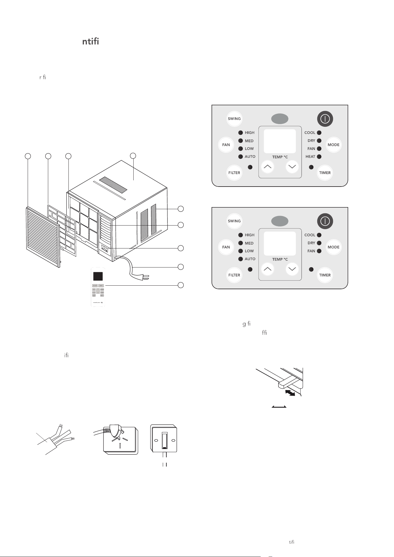
unit parts iden cation / operation instructions 9
Operating Instructions
1 Front panel
2 Ai
lter
3 Frame
4 Cabinet
5 Air inlet grille (outdoor side)
6 Air outlet grille
7 Electronic control keypad
8 Power supply cord and plug
9 Remote control
1 Power cord conductors are distinguished according to
colour as follows (see Fig.1)
2 For your safety and protection, this unit is earthed
through the power cord (see Fig.2)
Please contact the manufacturer or its service agent or a
similar qual
ed person if you want to replace it.
3 Be sure that the unit is being correctly grounded. The
wall outlet (Air-Break Switch) should be provided with
reliable earth wire.
4 The unit should be provided with an individual circuit
and the circuit breaker/fuse rating should be the same as
that of the power cord and wall outlet.
Controls
The electronic control keypad will look like one of the
following:
Reverse Cycle Models
Cooling only models
Vent control
The vent control is locat
ed above the control keypad.
The operation method is different on different models
(see the followin
gures).
For maximum cooling e
ciency, CLOSE the vent.
This will allow internal air circulation.
CLOSE VENT OPEN
CLOS
E OPEN
close open
To open the vent, set the lever to the right position.
To close it, set the lever in the left position.
Unit Parts Ide cation
1 2 3
4
5
6
7
8
9
power
cord
A
E
N
Fig. 1
Fig. 2
wall outlet
air break switch
E- earthwire, yellow/green
N- neutral wire, blue
A - active wire, brown
To open the vent, slide the lever to the left. To close it,
slide to the right.
Westinghouse Air Conditioning

10 operating instructions
Timer:
Press the "TIMER" keypad to activate the "auto start/auto
stop" timer function.
Auto start/stop programs can be set from 1/2-24 hours.
Dry:
In the Dry mode, the air conditioner will operate in the form
of a dehumid
.
Cooling:
The temperature settings are adjustable between 16°C
to 30°C . Cooling begins automatically when the room
temperature is 1°C above the set point, and stops when the
room temperature is 1°C below the set point. The fan will
not stop running.
Heat:
The temperature settings are adjustable between 16°C to
30°C in heating mode.
The default temperature setting is 24°C in heating mode and
the fan speed is optional.
Note:
Note:
When heating stops, there may be a slight delay of 30
seco
nds for the fan motor to stop.
Auto:
For the cooling only models, after selecting "AUTO" by
pressing the "MODE" button, the air conditioner will select
the appropriate operating mode from "FAN", "COOL" or
"DRY" based upon the temperature difference between the
actual and desired room temperature.
For the cooling and heating models, after selecting "AUTO"
by pressing the "MODE" button, the air conditioner will
select the appropriate mode for cool, heat or dry based
upon the
temperature difference between the actual and
desired room temperature. The default heating temperature
set point is 20°C, the default cooling temperature set point
is 25°C
Note: When activating the SLEEP mode when the unit is
in AUTO mode, the fan motor will change into LOW
speed mode immediately.
Operating instructions
Power:
Press the POWER keypad to turn the unit on/off.
(The TIMER keypad controls the auto start/stop feature
of the unit.)
Mode:
Press the "MODE" keypad to sele
ct the appropriate
operating mode. For the Reverse Cycle models (cooling &
heating), the mode selection will alternate between AUTO,
HEATING, COOLING, FAN and DRY. For the Cooling only
models, select the operating mode from AUTO, COOLING,
FAN and DRY. The green indicator light beside the "MODE"
option will illuminate, identifying the mode selected.
When using the DRY and AUTO mode, you cannot select a
fan speed. The fan motor operates on LOW speed in DRY
mode and on MED speed in
AUTO mode.
Note: There is no green indicator light for "Auto" mode.
When you select "Auto " mode, a beep will sound
indicating this "MODE" option was selected.
Temperature settings up:
Press the keypad to increase the set (operating)
temperature of the unit.
Each time the keypad is pressed the temperature increases
by 1°C with a maximum setting of 30°C
Temperature settings down:
Press the keyp
ad to decrease the set (operating)
temperature of the unit.
Each time the keypad i
s pressed the temperature decreases by
1°C with a minimum temperature of 16°C.
Fan:
Press this keypad button to activate the appropriate fan
speed setting. Each press of the button will alternate through
LOW, MED, HIGH fan speed options. The green indicator
light beside the FAN speed option will illuminate, identifying
the fan speed selected.
Swing:
Press the "SWING" keypad to activate the automatic air
swing (oscillation) feature.
The green indicator light adjacent to the "SWING" keypad
will illu
minate, identifying that the selected mode is
operational. The vertical louvers will oscillate back and
forth (side to side) automatically sweeping air around for
comfortable cooling/heating. To stop the air swing feature,
pressing the "SWING" keypad again, the green indicator
light adjacent to the keypad will go off.
When the SLEEP mode is activated, the green indicator light
beside the "SLEEP" function will illuminate.
Since the conditioned space is a closed or sealed area,
some degree of cooling will continue.
To help heat the room evenly. Keep fan speeds between
medium & high.
Westinghouse Air Conditioning
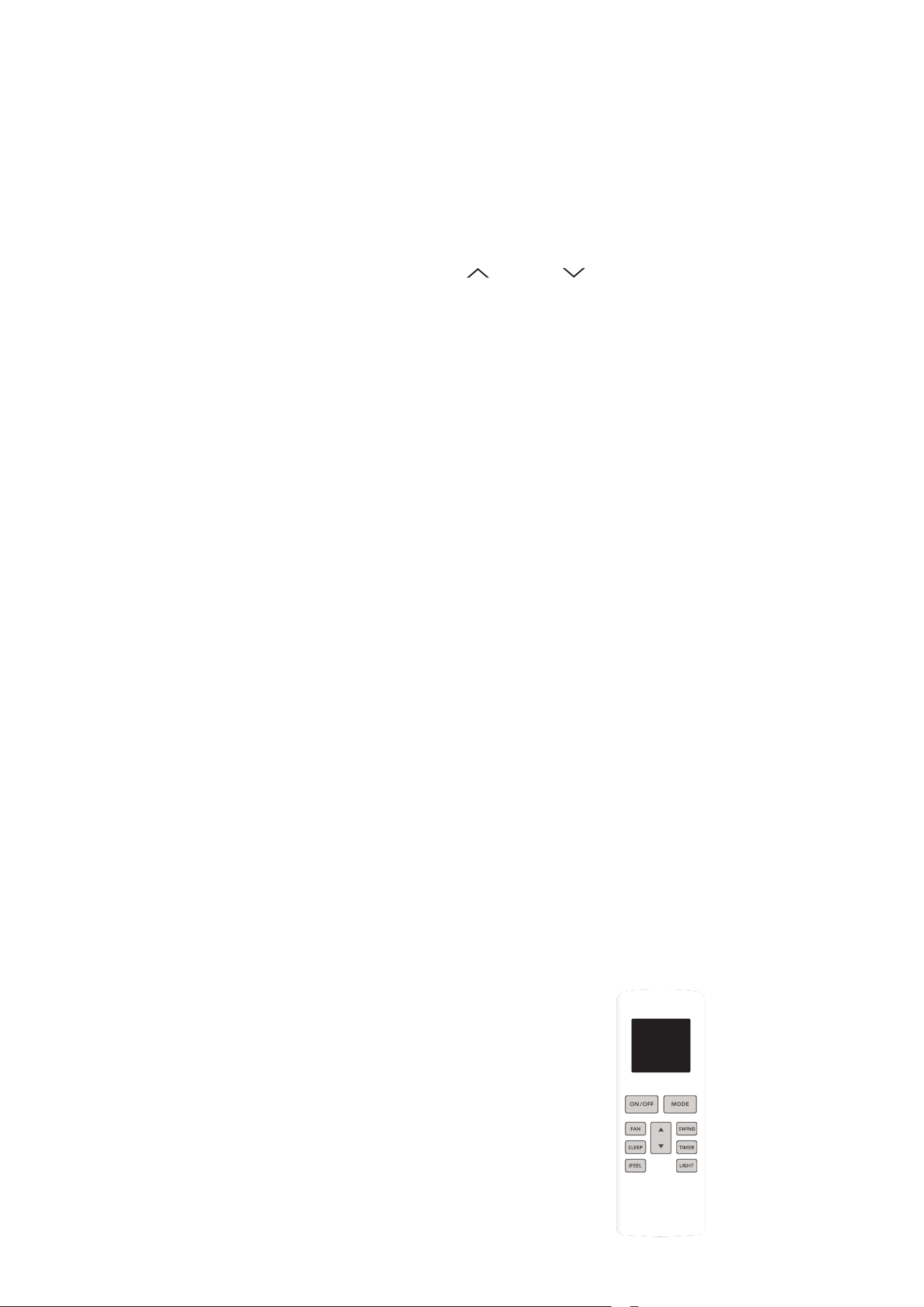
remote control features 11
The hand held remote control unit allows you to control
all operational aspects of your Air Conditioner, from the
convenience of your favourite armchair. Here are some things
you should know about to operate your Air Conditioner
with the hand held remote control.
Temperature:
Increases / Decreases operating TEMPERATURE only.
Power ON/OFF:
Turns the power to the main unit "on/off" only.
Mode:
Activates the "AUTO" (if applicable), "HEAT" (if applica
ble),
"COOL", "FAN" or "DRY" function.
Timer:
Activates the "auto START" or "auto STOP"
Sleep:
Activates the "SLEEP" mode.
Swing:
Activates the automatic air SWING (vertical) louver
oscillation) feature.
Fan:
Activates the FAN speed settings (HIGH, MED, LOW, AUTO).
Batteries:
To operate the hand held remote control, you will require two
AAA 1.5Volt batteries (included).
NOTE: Batteries should be replaced when:
a) No signal (beep) is heard from the main unit when
initiatin
g program commands from the remote
control to the main unit.
b) The main unit does not respond to the remote
control program commands.
Battery Replacement:
1 Slide the lower (battery) cover down (Located on rear of
remote control unit).
2 Insert two "AAA" Batteries inside the battery chamber
(as depicted inside the battery chamber).
3 Re-install lower battery cover.
4 If the remote control is not being used for extended time
periods, (vacation, off season) the batteries s
hould be
removed from the remote control unit.
Sleep:
Press and hold the "SWING" keypad for 2 seconds or use
the remote control to activate the "SLEEP" feature. In the
Cooling mode, the cooling temperature set point will
increase 1
O
C per hour after the "SLEEP" mode is selected.
Two hours later, the set point will continue at this
temperature and the fan motor will remain on LOW speed.
In the Heating mode, the heating temperature set point
will decrease 1
O
C per hour after the "SLEEP" mode is
selected. Two hours later, the set point will continue at this
temperature and the fan motor will remain on LOW speed.
Using the "SLEEP" mode will reduce noise creating a
comfortable sleeping environment.
Note: When activating the SLEEP mode in AUTO mode,
the set temperature will not change over time.
program from 0.5-24 hours (0.5 hour increments).
Westinghouse Air Conditioning
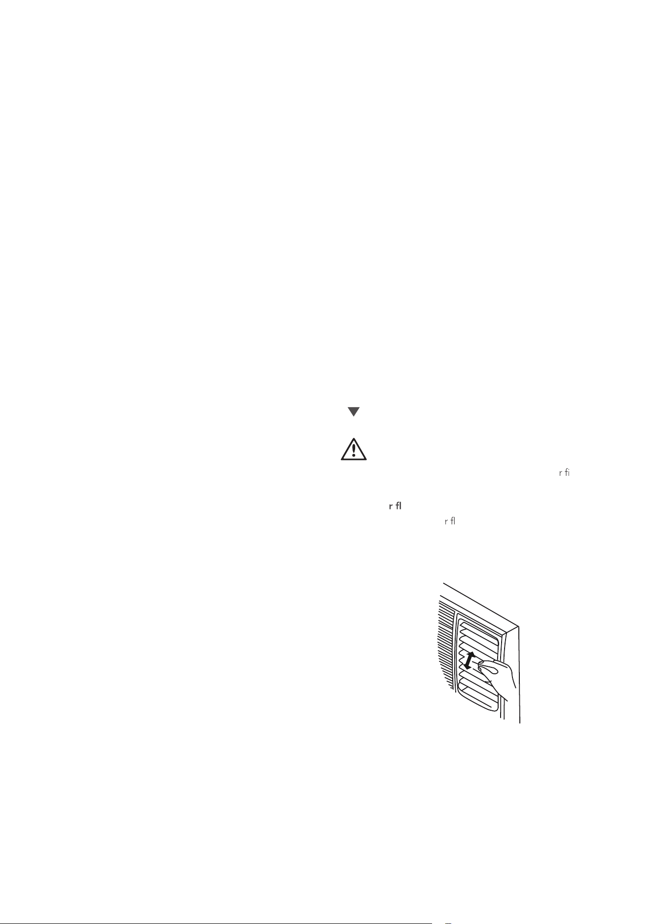
12 remote control features
Light:
Sleep:
Press the "SLEEP" button to activate the "SLEEP" feature.
Press the "SLEEP" button to deactivate the "SLEEP" feature.
In Cooling mode, the cooling temperature set point will
increase 1°C per hour after the "SLEEP" mode is selected.
After two hours, the set temperature will remain constant.
In Heating mode, the heating temperature set point will
decrease 1°C per hour after the sleep button is pressed and
then remain constant.
To change Cel
sius to Farenheit
With the air conditoner switched off, press the "MODE" and
" " buttons simultaneously to switch °C and °F.
NEVER operate the air conditioner without the ai
lter,
as dust/dirt particles can contribute to equipment failure.
Vertical ai ow adjustment (manually)
To adjust the vertical ai ow direction, adjust any one of the
horizontal louvre blades. When adjusting the horizontal
louver blades up or down, always keep the top or bottom
blades horizontal. This can effectively prevent water droplets
condensing on the front panel of the unit.
Remote Control Operating Instructions:
The hand held remote control unit operates within a range
of 7 metres (23ft) from the receiver located inside the unit.
Any obstruction between the receiver and the hand held
remote may cause signal interference, limiting the ability
to program the main unit.
Each time a remote control button is pressed, a beep will
sound indicating a command (signal) is transmitted and
received on the unit. When the command is received,
the appropriate fun
ction will be displayed (temporarily)
in the LED display window and the green indicator light
corresponding to the selection mode will illuminate on
the main control panel.
Note:
Note:
The LED display will default to show the ambient
room temperature within 10 seconds of all
program commands.
Power:
To turn the (air conditioner) power on/off, aim the remote
control at the receiver (window) on the unit and press the
"POWER" button.
Mode:
Press the "MODE" button to select either "AUTO
",
"HEATING", "COOLING", "FAN" or "DRY" mode (Cooling
& Heating model) or "COOLING", "FAN" or "DRY" mode
(Cooling only model).
Set cooling/heating/auto temperature:
Press the "TEMP" (up/down) buttons to select (increase/
decrease) the required operating temperature, the selected
temperature will appear (temporarily) in the LED display.
The temperature settings are adjustable between 16
O
C
and 31
O
C.
Fan:
Press the "FAN" button to select the required operating fan
speed
(HIGH, MED or LOW).
Swing:
Press the "SWING" button to activate the swing feature (the
vertical louvres will oscillate automatically from side to side).
Press the "SWING" button again to deactivate the
"SWING" feature.
Timer:
Auto:
Press the "AUTO" button to active the "AUTO" function and
the unit will be running according to room temperature.
Press the "TIMER" button to activate the "auto start/auto
stop" timer function. Under ON status, press the button to
set timer OFF; Under OFF status, press the button to set
timer ON. Time setting range is 0.5~24hours.
iFEEL:
Press this button to turn the control panel display On & Off.
Push this button to initiate the “iFEEL” feature, which allows
the indoor ambient temperature reading to be taken from
the remote control. The remote control will send this signal
to the air conditioner every 10 minutes interval until press
the “iFEEL” button again. The air-conditioner will cancel
the “iFEEL” feature automatically if the indoor unit
dose not receive the signal from the remote control
within a 10 minutes period.
The display will be On as a default setting.
Westinghouse Air Conditioning
CAUTION
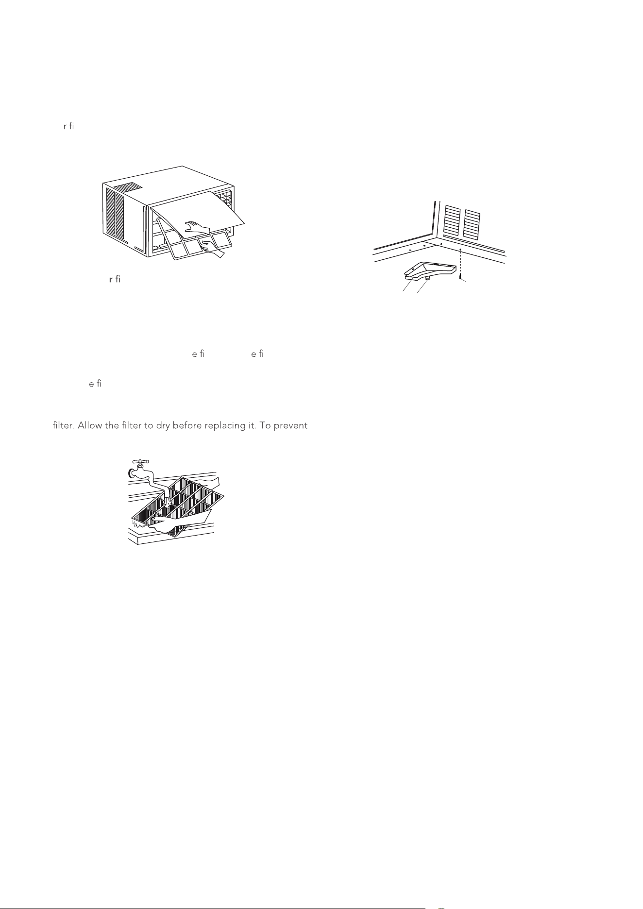
remote control features/installation instructions 13
Air Filter
The ai
lter behind the inlet grille should be checked and
cleaned at least once every 2 weeks (or as necessary) to
maintain optimal performance of the air conditioner.
SEAL
DRAIN
JOINT
RUBBER
PLUG
Removing the ai lter
1 The grille can be opened from the bottom for easy
maintenance after installation.
2 Open the inlet grille by pulling on the openings in the
bottom of the grille
3 Pull the tab slightly to release th
lter. Pull th lter
forward to remove it.
4 Clean th lter with warm soapy water. The water should
be below 40°C to prevent damage.
5 Rinse off and gently shake off any excess water from the
damage, do not dry in direct sunlight.
SEAL
DRAIN
JOINT
RUBBER
PLUG
AUTO restart
During a power failure, the air conditioner will stop
completely. When the power is restored, the air conditioner
will start automatically with all the previous settings
preserved in the memory.
The treatment of condensed water
1 Take out the drain pan and screws (provided within your
air conditioner accessories bag).
2 Install the drain pan at the bottom of the unit and secure
it with the screws provided.
3 Connect a suitable sized drain hose (not supplied
) to the
drain outlet located on the underside of the drain pan.
drain
pan
screw
drain
outlet
Maintenance
Westinghouse Air Conditioning
14 installation instructions
Note: unit may be supported by a
solid frame from below or
by a hanger from a solid
overhead support.
Preferred method of installation into a timber
framed wall, partition or window.
Flash or seal around external
Wall frame or architrave
Flash or seal around external
Wall frame or architrave
Ensure louvres
are entirely
outside the wall
Drain pan
Steadying bracket
(one per side)
Solid timber support
Study timber
frame
Timber frame
wall or partition
Sturdy timber
frame all
round unit
Timber framed
Wall or partition
Drain pan
External support
frame at balance
point of A/C
Alternately, brackets
as illustrated below
may be used.
Alternative method of installation if external
45° brick cut away
to clear louvres
Louvre
support cannot be provided.
AIR IN
AIR OUT
100mm minimum
AIR IN
OPTION A
OPTION B
AIR OUT
100mm
AIR IN
TOP
VIEW
BRICK
WALL
AIR IN
ash or seal around external
wall frame of architrave
sturdy timber
frame all
around unit
timber framed
wall or partition
external support frame
at balance point of A/C
preferred method of installation into a timber
framed wall, partition or window
drain
Installation of the unit into the housing
1 Slide the unit into the housing until it i
rmly against the
rear of the housing. Care is required to ensure the foam
sealing strips on the housing remain in position.
2 Connect the air conditioner to the power and position
excess cord length beneath the air conditioner base.
3 Engage the chassi
xing brackets into the bottom
housing rail and secure to the base with the
screws provided.
4 Remove the front panel from it's carton and plastic bag
an as per the Installation lnstruction.
5 Switch unit on. Check for operation of the unit and check
for vibration in the installation.
6 Fit the drain pan to the housing and run a drain line to a
suitable location if required.
Installing the unit into the wall
Note: unit may be supported by a
solid frame from below or
by a hanger from a solid
overhead support.
Preferred method of installation into a timber
framed wall, partition or window.
Flash or seal around external
Wall frame or architrave
Flash or seal around external
Wall frame or architrave
Steadying bracket
(one per side)
Solid timber support
Study timber
frame
Timber frame
wall or partition
Sturdy timber
frame all
round unit
Timber framed
Wall or partition
External support
frame at balance
point of A/C
Alternately, brackets
as illustrated below
may be used.
Alternative method of installation if external
45° brick cut away
to clear louvres
support cannot be provided.
AIR IN
AIR OUT
100mm minimum
AIR IN
OPTION A
AIR IN
air in
air in
air out
100mm minimum
option A
air in
Note: unit may be supported by a
solid frame from below or
by a hanger from a solid
overhead support.
Preferred method of installation into a timber
framed wall, partition or window.
Flash or seal around external
Wall frame or architrave
Flash or seal around external
Wall frame or architrave
Ensure louvres
are entirely
outside the wall
Drain pan
Steadying bracket
(one per side)
Solid timber support
Study timber
frame
Timber frame
wall or partition
Sturdy timber
frame all
round unit
Timber framed
Wall or partition
Drain pan
External support
frame at balance
point of A/C
Alternately, brackets
as illustrated below
may be used.
Alternative method of installation if external
45° brick cut away
to clear louvres
45° brick cut away
to clear louvres
Front
Louvre
support cannot be provided.
AIR IN
AIR OUT
100mm minimum
AIR IN
OPTION A
OPTION B
BRICK
WALL
AIR OUT
A
100mm
100mm
IR INAIR IN
TOP
VIEW
BRICK
WALL
AIR IN
air out
air in
air in
louvre
100mm
100mm
front
45° brick cut away
to clear louvres
45° brick cut away
to clear louvres
option B
Select the best location
1 To avoid vibration and noise, make sure the unit is
installed securely an
rmly.
2 Install the unit where the sunlight does not shine directly
on the unit.
If the unit receives direct sunlight, build an awning to
shade the cabinet.
3 There should be no obstacle, such as a fence or wall,
within 50cm from the back of the cabinet because it will
prevent heat radiation of the condensor.
Restriction of outside air will greatly reduce the cooling
and heating e
ciency of the air conditioner.
4
5 Install the unit with its bottom portion 75~150cm above
th
oor level.
6 The power cord must be connected to an independent
circuit. The yellow/green wire must be grounded.
7 Based on calculations in compliance with AS60335.2.40
there is no minimum saf
oor area for the installation of
the air conditioners described in this manual.
All side louvers of the cabinet must remain exposed to the
outside of the structure.
less than 220mm
more than 160mm
wall thickness is less than 220mm
make rear of the airconditioner (outside)
lower than the front of the airconditioner
(inside) to allow water to drain
3°~4°
Installation of the Housing
1 Remove the air conditioner from its packaging, remove
ing screws and slide the air conditioner out of its
housing (Refer to Installation Steps).
2 Prepare the hole in the wall so that the bottom of
the housing is well supported, the top has minimum
clearance and the air inlet louvers have clearance as
shown below in options A and B. Holes from the outside
through to the cavity should be sealed. The housing
should slope down towards the rear by about 3°~4° to
allow water formed during operation to drain.
3 Install the housing into the wall and secure. Ens
ure the
foam seals are not damaged. Flash, seal o ll gaps
around the inside and outside to provide satisfactory
appearance and protection against the weather, insects
and rodents.
Note: Unit may be supported by a solid frame from below or
by a hanger from a solid overhead support.
Installation Instructions
Install the unit with rear angled down so as not to
leak condensed water into the room (about 3°~4°
angle with level).
Westinghouse Air Conditioning
CAUTION
installation instructions 15
4 Reinstall the chassi xing bracket removed earlier
(See Fig.5).
Install the frame.
1 Install the frame making sure not to jam the power
supply cable (See Fig.8).
2 Fix the screws on the frame.
Step 5. Install the ai
lter and front panel.
1 Install the ai lter into the frame's slot from upside to
underside (See Fig. 2).
2 Hang the front panel on the frame's top edge, then press
the front panel into the frame edges until you hear clicks.
Installation Steps
Step 1. Remove the front panel and the ai lter
1 Hold the slot under the front panel, then lift it up and
outwards, and remove the front panel (See Fig.1).
2 Pinch the handle under the ai
lter, bend th lter gently
and remove it from the slots (See Fig.2).
Step 2. Remove the frame.
1 R
1
2
3
4
The drain plug is tted from the factory to capture
condensed water to maximise the cooling efciency of this
product.
There may be some sound of splashing water under some
conditions.
This conguration is used for testing the capacity and
efciency of this product for performance rating purposes.
The drain plug can be removed to drain water to a specic
location and/or reduce noise but drain plug removal can
reduce performance.
emov
xing screws from the frame (See Fig.3). Screws
can be in different positions of the frame for different
models, usually there are 2 screws at the rear of the
larger units and one screw at the mid front right. Smaller
units have less screws.
2 Release the front panel lugs on the side of the front
panel from the outer frame slots at top, middle and
bottom where they meet. Grasp the left corner of the
frame's underside, then loosen the frame (See Fig.4).
Step 3. Installation.
1 Remove th xing screw on the chassi xing bracket,
then remove the chassi xing bracket (See Fig.5).
2 Grasp the handle on the chassis and carefully slide the
air conditioner out of the cabinet (See Fig.6).
3 Push the unit chassis into the cabinet (See Fig.7).
Fig. 1
Fig. 3
Fig. 5
Fig. 2
Fig. 7
Fig. 8
Fig. 4
Fig. 6
Westinghouse Air Conditioning
Drain plug (Cooling only models)
Pull out the drain plug
manually

16 troubleshooting
Troubleshooting
Troubleshooting Tips
Save time and money! Review the chart below first and you
may not need to call for service.
Normal operation
• You may hear a pinging noise caused by water being
picked up and thrown against the condenser on rainy
days or when the humidity is high. This design feature
helps remove moisture and improve efficiency.
• You may hear the thermostat click when the compressor
cycles on and off.
• Water will collect in the base pan during high humidity
or
on rainy days. The water may overflow and drip from the
outdoor side of the unit.
• The fan may continue to operate when the compressor
has cycled off.
Abnormal operation
Problem
Possible
causes
What to do
Air
conditioner
does not start
The air
conditioner is
unplugged.
Make sure the air conditioner
plug is pushed completely into
the outlet and switched on.
The fuse is
blown/circuit
breaker is
tripped.
Check the house fuse/circuit
breaker box and replace the
fuse or reset the breaker.
Power failure.
If power failure occurs, switch
off and disconnect/unplug the
power cord. When power is
restored, reconnect (plug in)
the power cord, switch o
n the
power and wait 3 minutes to
restart the air conditioner
to prevent tripping of the
compressor overload.
Air
conditioner
does not cool
as it should
Airflow is
restricted.
Make sure there are no
curtains, blinds, or furniture
blocking the front of the air
conditioner.
The air filter
is dirty.
Clean the filter at least every
2 weeks. See the operating
instructions section.
The room
may have
been hot.
When the air conditioner is
first turned on you need to
allow time for the room to
cool down.
Col
d air is
escaping.
Check for open furnace floor
registers and cold air returns.
Set the air conditioner's vent
to the closed position.
Cooling coils
have iced up.
See Air Conditioner Freezing
Up below.
Air
conditioner
freezing up
Ice blocks the
air flow and
stops the air
conditioner
from cooling
the room.
Set the fan at MED or HIGH
until the ice melts.
Westinghouse Air Conditioning
notes 17
Notes
Westinghouse Air Conditioning
18 notes
Notes
Westinghouse Air Conditioning
This document sets out the terms and conditions of the product
warranties for Westinghouse Appliances. It is an important document.
Please keep it with your proof of purchase documents in a safe place
for future reference should there be a manufacturing defect in your
Appliance. This warranty is in addition to other rights you may have
under the Australian Consumer Law.
1. In this warranty:
(a) ‘ACL’ or ‘Australian Consumer Law’ means Schedule 2 to the
Competition and Consumer Act 2010;
(b) ‘Appliance’ means any Electrolux product purchased by you and
accompanied by this document;
(c) ‘ASC’ means Electrolux’s authorised serviced centres;
(d) ‘Westinghouse’ is the brand controlled by Electrolux Home Products Pty
Ltd of 163 O’Riordan Street, Mascot NSW 2020, ABN 51 004 762341 in
respect of Appliances purchased in Australia and Electrolux(NZ) Limited
(collectively “Electrolux”) of 3-5 Niall Burgess Road, MountWellington, in
respect of Appliances purchased in New Zealand;
(e) ‘Warranty Condition’ means:
(i) evidence by the customer that the Appliance was
installed
in accordance with Electrolux installation guidelines as set out
in the installation manual;
(ii) the Appliance rating is correct for the size and thermal
characteristics of the room;
(iii) the Appliance has been regularly maintained in accordance
with Electrolux guidelines as set out in the user manual;
(iv) the Appliance is designed for providing human comfort and
should be used under ambient conditions as set out in the
product specifications and general air quality conditions.
(f) ‘Warranty Period’ means the period specified in clause 3 of this
warranty;
(g) ‘you’ means the purchaser of the Appliance not having purchased
the Appliance for re-sale, and ‘your’ has a corresponding meaning.
2. Application: This warranty only applies to new Appliances, purchased
and used in Australia or New Zealand and is in addition to (and does
not exclude, restrict, or modify in any way) other rights and remedies
under a law to which the Appliances or services relate, including any
non-excludable statutory guarantees in Australia and New Zealand.
3. Warranty Period: Subject to these terms and conditions, this warranty
continues for in Australia for a period of 60 months and in New Zealand
for a period of 60 months, following the date of original purchase of the
Appliance.
4. Repair or replace warranty: During the Warranty Period, Electrolux
or its ASC will, at no extra charge if your Appliance is readily accessible
for service, without special equipment and subject to these terms and
conditions, repair or replace any parts which it considers to be defective.
Electrolux may, in its absolute discretion, choose whether the remedy
offered for a valid warranty claim is repair or replacement. Electrolux or its
ASC may use refurbished parts to repair your Appliance. You agree that
any replaced Appliances or parts become the property of Electrolux.
5.
Travel and transportation costs: Subject to clause 7, Electrolux will
bear the reasonable cost of transportation, travel and delivery of the
Appliance to and from Electrolux or its ASC. Travel and transportation
will be arranged by Electrolux as part of any valid warranty claim.
6. Proof of purchase is required before you can make a claim under this
warranty.
7. Exclusions: You may not make a claim under this warranty unless the
defect claimed is due to faulty or defective parts or workmanship. This
warranty does not cover:
(a) light globes, batteries, filters or similar perishable parts;
(b) parts and Appliances not supplied by Electrolux;
(c) cosmetic damage which does not affect the operation of the
Appliance;
(d) dam
age to the Appliance caused by:
(i) negligence or accident;
(ii) misuse or abuse, including failure to properly maintain or service;
(iii) improper, negligent or faulty servicing or repair works done by
anyone other than an Electrolux authorised repairer or ASC;
(iv) normal wear and tear;
(v) power surges, electrical storm damage or incorrect power supply;
(vi) incomplete or improper installation;
(vii) incorrect, improper or inappropriate operation;
(viii) insect or vermin infestation;
(ix) failure to comply with any additional instructions supplied with
the Appliance; and
(x) a breach of the Warranty Conditions.
In addition, Electrolux is not liable under this warranty if:
(a) the Appliance has been, or Electrolux reasonably believes that the
Appliance has been, used for purposes other than those for which
the Appliance was intended, including where the Appliance has
been used for any non-domestic purpose;
(b) the Appliance is modified without authority from Electrolux in writing;
(c) the Appliance’s serial number or warranty seal has been removed
or defaced.
8. Ho
w to claim under this warranty: To enquire about claiming under
this warranty, please follow these steps:
(a) carefully check the operating instructions, user manual and the
terms of this warranty;
(b) have the model and serial number of the Appliance available;
(c) have the proof of purchase (e.g. an invoice) available;
(d) telephone the numbers shown below.
9. Australia: For Appliances and services provided by Electrolux in
Australia: Electrolux goods come with guarantees that cannot be
excluded under the Australian Consumer Law. You are entitled to a
replacement or refund for a major failure and for compensation for any
other reasonably foreseeable loss or damage. You are also entitled to
have the Appliance repaired or replaced if the Appliance fails to be of
acceptable quality and the failure does not amount to a major failure.
‘Acceptable quality’ and ‘major failure’ have the same meaning as
referred to in the ACL.
10. New Zealand: For Appliances and services provided by Electrolux
in New Zealand, the Appliances come with a guarantee by Electrolux
pursuant to the provisions of the Consumer Guarantees Act, the Sale
of Goods Act and the Fair Trading Act. Where the Appliance was
purchased in New Zealand for commercial purposes the Consumer
Guarantee Act does not apply.
Confidentiality: You accept that if you make a warranty claim, Electrolux
and its agents including ASC may exchange information in relation to you
to enable Electrolux to meet its obligations under this warranty.
11.
Warranty
FOR SALES IN AUSTRALIA AND NEW ZEALAND
WESTINGHOUSE WINDOW/WALL AIR CONDITIONER
Westinghouse_Warr_July24
Important Notice
Before calling for service, please ensure that the steps listed in clause 8 above have been followed.
AUSTRALIA
FOR SERVICE
or to find the address of your nearest
authorised service centre in Australia
PLEASE CALL 13 13 49
For the cost of a local call
FOR SPARE PARTS
or to find the address of your nearest
spare parts centre in Australia
PLEASE CALL 13 13 49
For the cost of a local call
NEW ZEALAND
FOR SERVICE
or to find the address of your nearest
authorised serv ice centre in New Zealand
PLEASE CALL 0800 10 66 10
FOR SPARE PARTS
or to find the address of your nearest
spare parts centre in New Zealand
PLEASE CALL 0800 10 66 20
warranty 19Westinghouse Air Conditioning

ver1_Feb2025
and WESTINGHOUSE are trademarks of Westinghouse Electric Corporation.
Used under license. All Rights Reserved.