1
PRODUCT
REGISTRATION
Register your product today for a
chance to win an ISOBAR
®
surge
protector in our monthly drawing!
Tripplite.Eaton.com/warranty
Quick Start Guide
Purchased product
may differ from image.
Model:
B013-330-USB
KVM Extender
Cat5 USB

2
1. Important Safety Instructions
2. Product Features
• The device must only be opened by a qualified technician.
• Disconnect device from AC mains before service operation!
• Use of this equipment in life support applications where failure of
this equipment can reasonably be expected to cause the failure of
the life support equipment or to significantly affect its safety or
effectiveness is not recommended.
• 328 ft. (100 m) CAT5 extension
• Built-in 2-port KVM switching feature on the receiver unit
• RX-PC/TX-PC KVM port selection on the RX unit by a front-panel
button or keyboard hotkeys
• Remote-site (receiver) console access mode selection (Full-access/
No-access/ View-only) by local-site transmitter unit's panel button
and keyboard hotkey
• USB keyboard/mouse connectivity support on both local-site
(transmitter) console and remote-site (receiver) console
• OSD menu-driven control for easy system configuration
• Keyboard hotkey control for configuration and operation
• Full keyboard/mouse emulation to support compatible Microsoft/
Logitech functional keyboard/mouse products
• Transmitter unit's EDID selection support for local-site/remote-site
monitors by receiver unit's OSD menu
• Analog video resolution up to 1920 x 1200
• Firmware upgradeable via dedicated USB port

3
3. Package Contents
• Transmitter (TX) Unit x 1
• Receiver (RX) Unit x 1
• USB KVM Combo Cable x 2
• USB-A to USB-B Upgrade cable x1
• Power Adapter (DC 5V) x 2
• Quick Start Guide x 1
4
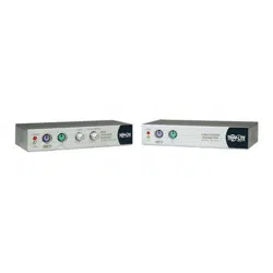
4. Front/Rear Panels
The front and back panels are where the various connectors are
located on the two pieces of the CAT5 USB KVM Extender Set. Before
you connect these two units to any computer, cabling accessories or
peripherals, locate the main connectors you are going to encounter
when setting up the system.
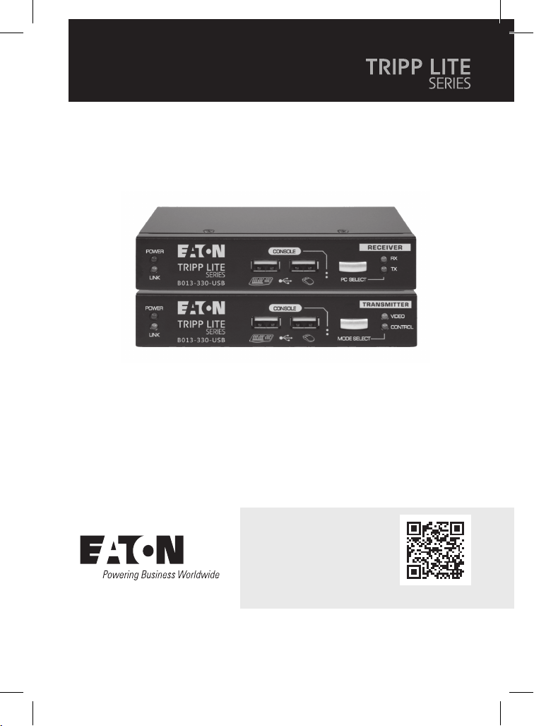
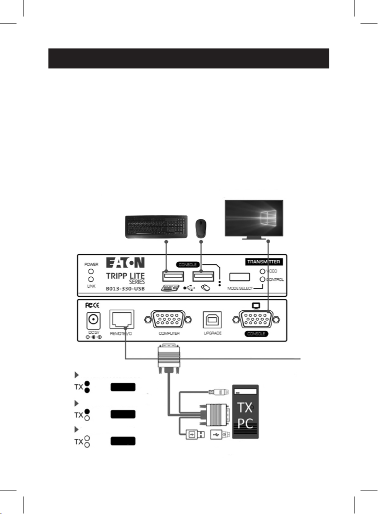
Transmitter Unit (Local-end Connection)
Transmitter (TX) unit - Front Panel
1
POWER LED - Illuminates when power is on
2
LINK LED - Illuminates when linkage is established
3
USB keyboard connector
4
USB mouse connector
5
MODE SELECT button for receiver console (Full Access/No Access/
View Only)
6
VIDEO LED Indicator - Illuminates when receiver console monitor
is allowed
7
CONTROL LED - Illuminates when receiver console keyboard/
mouse is allowed
1
1
6
6
2
2
7
7
3
3
4
4
5
5
5
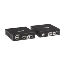
4. Front/Rear Panels
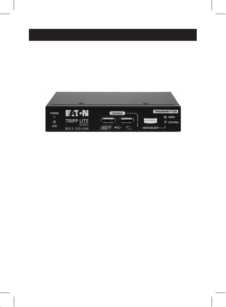
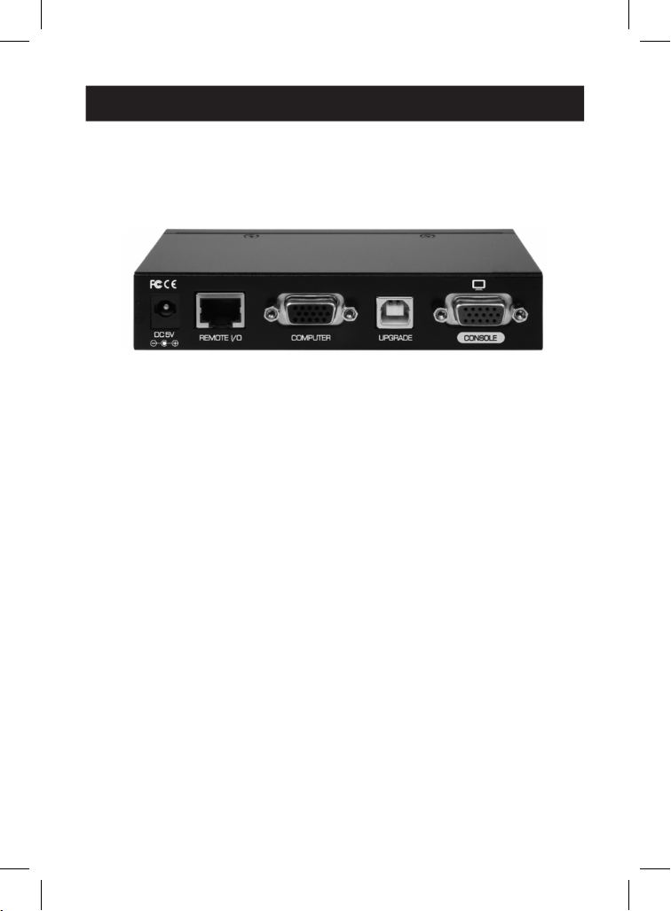
Transmitter (TX) unit - Rear Panel
8
Power jack - DC 5V, center-positive
9
CAT5 Extension Port - RJ45, connects to the receiver unit via a
CAT.X UTP cable, maximum 328 ft. (100 m)
J
COMPUTER port - HDB-15 (VGA + USB), connects to the TX-site
computer using an included 3-in-1 KVM combo cable
K
UPGRADE port - USB Type-B, dedicated for firmware upgrades
L
Transmitter CONSOLE video port - HDB-15 (VGA), connects to TX
unit's monitor
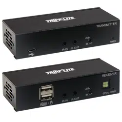
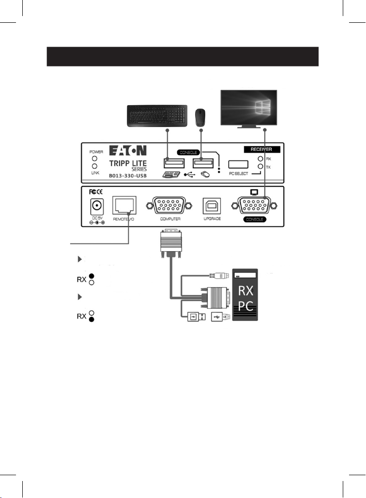
Receiver Unit (Remote-End Connection)
Receiver (RX) unit - Front Panel
1
POWER LED - Illuminates when power is on
2
LINK LED - Illuminates when linkage is established
3
USB keyboard connector
4
USB mouse connector
5
PC SELECT button - Toggles connection of the receiver console to
remote-site (RX) / local-site (TX) computers
8
8
9
9
J
J
K
K
L
L
1
1
6
6
2
2
7
7
3
3
4
4
5
5
6
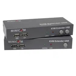
4. Front/Rear Panels
6
RX LED Indicator - Illuminates when the RX console is switched to
connect to the RX PC
7
TX LED Indicator - Illuminates when the RX console is switched to
connect to the TX PC
Receiver (RX) unit - Rear Panel
8
Power jack - DC 5V, center-positive
9
CAT5 Extension Port - RJ45, connects to the transmitter unit via a
CAT.X UTP cable, maximum 328 ft. (100 m)
J
COMPUTER port - HDB-15 (VGA + USB), connects to the RX-site
computer using an included 3-in-1 KVM combo cable
K
UPGRADE port - USB Type-B, dedicated for firmware upgrades
L
Receiver CONSOLE video port - HDB-15 (VGA), connects to RX
unit's monitor
8
8
9
9
J
J
K
K
L
L

7
5. Installation
Before you install the TX/RX units of the CAT5 USB KVM Extender
B13-330-USB, ensure the following is ready:
1. The computer for extension should be one with USB interfaces.
2. Check the display mode of the computer to be within 1920 x 1200
resolution and that the refresh rate is set at 30 or 60 Hz.
3. Prepare two sets of keyboards, mice and monitors: one set for
local-site transmitter console and the other set for remote-site
receiver console.
4. The two monitors used (one at the TX site and the others at the RX
site) should be of the same resolution, and ideally the same
model.
5. Since the CAT5 USB KVM extender only supports standard 5-key
mouse and keyboard, any advanced mouse/keyboard function will
not be supported by the CAT5 extender.
6. Use good quality CAT.X UTP cable, maximum 328 ft. (100 m).
Note: a high-quality cable will ensure better video quality even over longer
distances. Signal degradation increases as the cabling distance increases.
7. The choice of path of the CAT.X UTP cable should not only
consider the shortest path, but also consider any significant
sources of electromagnetic interference.
8. There should be power outlets near where you locate the
extenders. Take the package items out of the box and begin
installation.
Take the package items out of the box and begin installation.

8
5. Installation
Plan the layout path and deploy the UTP cable for
extension
1. Plan the path through which the CAT5 cable will be deployed
across the distance between the transmitter and the receiver. You
should choose the layout path not only based on shortest length
consideration, but also on least electromagnetic interference.
2. Lay out the UTP cable according to your planned path.
Configuring Transmitter Console
3. Connect one end of a CAT5 cable to the CAT5 extension port
(connector
9
) of the transmitter.
4. Connect the power adapter to the transmitter (connector
8
) to
power it up before connecting any computer or other cables to it.
5. Connect the transmitter to the TX PC, using the USB KVM combo
cable (connector
J
).
6. Connect a keyboard, mouse and monitor to the transmitter’s
console ports (connectors:
3
,
4
and
L
).
7. Power on the TX PC, and check if the keyboard, mouse and video
are working well, and then go on the following steps.
Configuring the Receiver Console
8. Connect the CAT5 cable from the transmitter to the CAT5
extension port (connector
9
) of the receiver.
9. Connect the power adapter to the receiver’s power jack (connector
8
) to power it up before connecting any devices to it.
10. Connect a keyboard, mouse, and monitor to the receiver’s
console ports (connector
3
,
4
and
L
).
11. Check if the keyboard, mouse and monitor are working well. At
this time, the video output of the RX unit might be blurry since it
hasn't been adjusted and optimized yet.
9
5. Installation
12. Adjust the video parameters to optimize the video display output
of the RX unit (refer to OSD Menu\Video Setting Page section
for details).
13. Connect with the USB KVM combo cable (included) between the
receiver (computer port
J
) and the VGA and USB ports of the RX
PC.
B013-330-USB CAT5 USB KVM Extender Configuration
Diagram
Local-site Console
to Remote-site Console
Local-site Monitor
Local-site Keyboard/Mouse
Cat.X Cable (328 ft. / 100 m)
VGA-enabled PC (TX site)
PS/2
VGA
USB
Full
View
Deny
USB to PS/2
Adaptor
KVM
Combo
Cable
RX full-access mode
Video
Control
Video
Control
Video
Control
RX view-only mode
RX no-access mode
10
5. Installation
Remote-site Console
to Local-site Console
Remote-site Monitor
Remote-site Keyboard/Mouse
VGA-enabled PC (RX site)
PS/2
VGA
USB USB to PS/2
Adaptor
KVM
Combo
Cable
Remote-site KVM port
(RX-site PC)
Local-site KVM port
(TX-site PC)
Video
Control
Video
Control
11
6. Operation
On the receiver unit, the OSD (on-screen display) Menu control is
available to facilitate more intuitive operations. Users can configure
various settings in the RX unit's OSD Menu:
OSD Menu
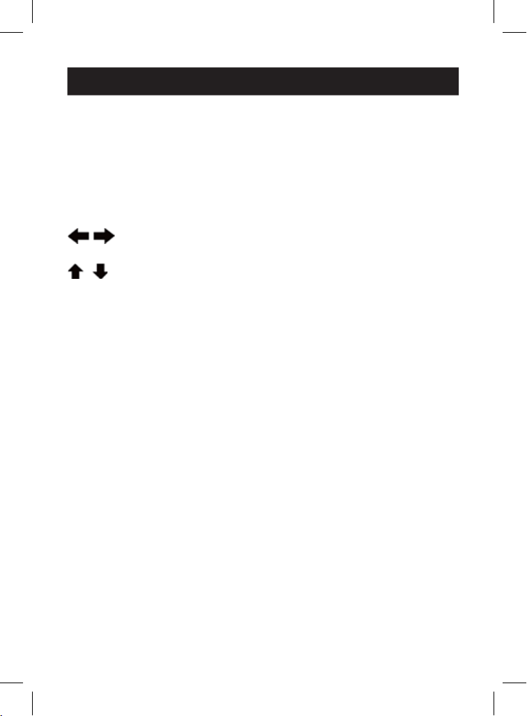
Following keys are used to operate the OSD Menu:
Esc: Exit the current page.
: Change the value in the selected option with LEFT/RIGHT
keys.
: Navigate options of the current page with UP/DOWN keys.
F10: Log out of the OSD Menu manually. (Please note that the logout
feature is unavailable if password protection is not enabled).
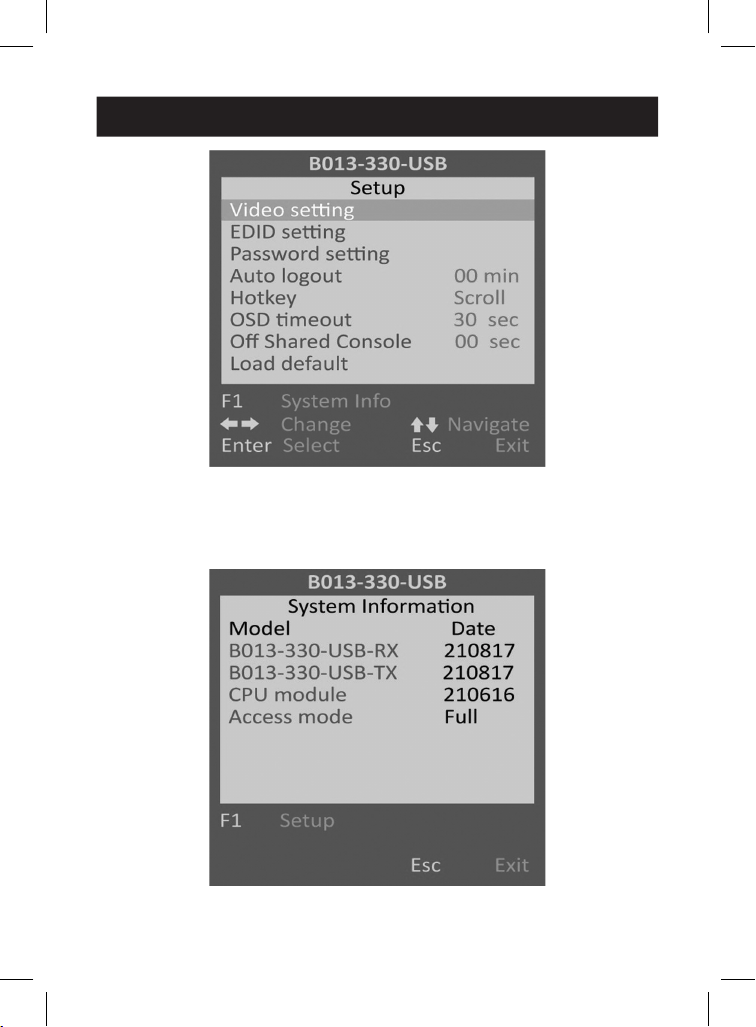
Setup Main Page
Below is the Setup Main Page of the OSD Menu when you hit the
following hotkey: [Scroll Lock], [Scroll Lock], [Space Bar], to bring
up the OSD Menu.
Note: The leading two same consecutive keystrokes are defined as the Hotkey
Preceding Keys, such as the [Scroll Lock] key. There are two methods to change
the Hotkey Preceding Key:
1. OSD Menu\Setup Main Page\Hotkey Option
2. Keyboard Hotkey (Hotkey Preceding Key Change is only available on receiver
unit)
12
6. Operation
Setup Main Page
System Information Page
Press the [F1] key to view the System Information Page.
System Information Page
13
6. Operation
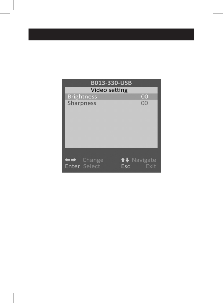
Video Setting Page
On this page, you can configure various video parameters such as
Brightness and Sharpness to optimize the video display result on
the monitor of the RX unit located up to 328 ft. (100 m) away from the
TX unit, if neccessary.
Video Setting Page
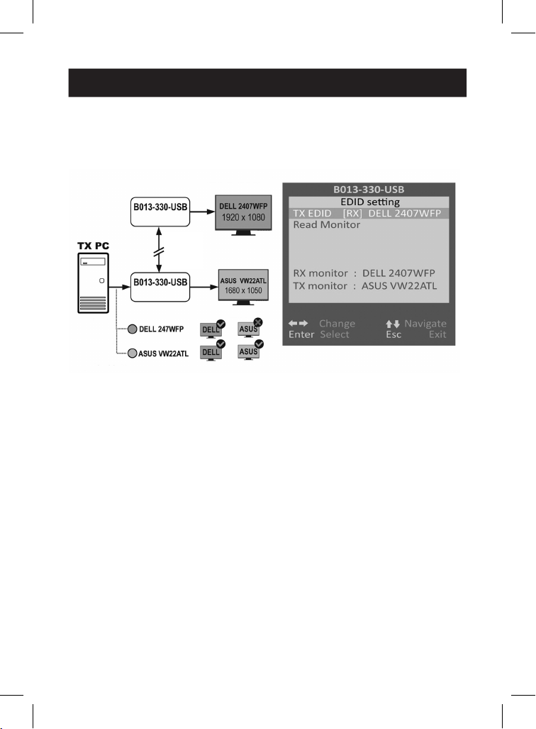
EDID Setting Page
With the TX EDID option on this page, users can select whether to
request the TX unit to apply the TX monitor's EDID data or the RX
monitor's EDID data. This helps resolve issues that might arise due to
the differences in resolution between the TX and RX monitors.
14
6. Operation
To update the EDID data manually, select the Read Monitor option
and then press the [Enter] key. The updated monitor EDID data of
TX/RX units will be listed as below.
Note: Use two monitors of the same model/resolution for both TX and RX units to
avoid the issue illustrated above.
RX Unit
EDID Setting Page
TX Unit
The inconsistent EDID issue of using different model
monitors
DELL and ASUS are trademarked brands owned by thier respective companies.
RX Monitor
TX Monitor
(Loop-back)
CAT.X
328 ft.
(100 m)
Out of Range!
TX PC
Video
Output
EDID
15
6. Operation
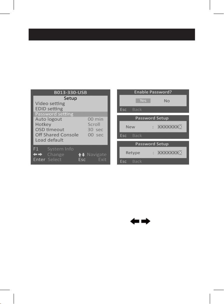
Password Setting Option/Page
Disable/Enable the Password Protection feature. After you manually
logout or auto logout with the set timeout, you will be requested to
input a password to access the receiver console again.
Note: Keep your password secure. Failure to do so may require you to contact
your local dealer for technical support.
Password Setting Option Password Setting Page
Auto Logout Option: [0 (Default), 1, 2, 3, 4, 5, 6, 7, 8, 9,10] Disable/
Enable the OSD Logout timeout (0~10min, 0 = Disable).
The Auto logout time can be configured from 0 (Disable) up to 10
minutes. If password protection is not enabled, Auto logout will not
function.
Hotkey Option: [Scroll (Default)]
To assign the Hotkey Preceding Key, press to select among
[Scroll], [Caps], [Number] and [F12] options to correspond [Scroll
Lock], [Caps Lock], [Num Lock], or [F12] keys, respectively.
OSD Timeout Option: [0, 20, 25, 30 (Default), 35, 40, 45, 50, 55, 60]

16
6. Operation
Configure the OSD timeout value, starting at 20 seconds, with an
increment of 5, right up to 60 seconds (0 = Disable).
Off Shared Console Option: [0 (Default), 3, 5, 10, 20, 30]
Configure the deadlock timeout value for the Console Control (0 =
Disable).
Note: The local-site (transmitter) console and the remote-site (receiver) console
switching-engaged priority offers the “Deadlock Function”. The deadlock function
is to keep the priority of the first-activated console user who is operating their
keyboard/mouse to the selected PC. The other (second-activated) console user can
only get to operate their keyboard/mouse once the first-activated console user has
stopped operating their keyboard/mouse for the duration of the deadlock timeout
set here.
If the Deadlock Function is enabled, the transmitter unit’s panel LED
indicators “VIDEO” and “CONTROL” will flash, until the previous
console user who operated their keyboard/mouse stops operating
the keyboard/mouse for the duration of the deadlock timeout set
here.
Note: The deadlock timeout function will not work if two consoles are not
connected to PCs.
Load Default Option: Restores the receiver unit back to factory
default settings.
Change the Hotkey Preceding Key (only available on
receiver unit)
A keyboard hotkey includes 3 or more consecutive keystrokes. The
leading two same consecutive keystrokes are defined as the Hotkey
Preceding Keys. To change the Hotkey Preceding Key for your
keyboard hotkeys, please hit the following hotkey:
[Scroll Lock], [Scroll Lock], [H], [y]
Note: [y] can be either [Caps Lock], [F12], or [Num Lock] key which serves as the
new Hotkey Preceding Key to replace the default [Scroll Lock] key.
Note: This hotkey preceding key change only applies to the receiver console and
doesn't apply to the transmitter console. In addition to changing the hotkey
preceding key at the receiver console, users can bring up the RX unit's OSD menu
to change the hotkey preceding key as instructed in the previous section.
17
6. Operation
Select Receiver Console Connection with the Remote-
site PC (Receiver-End) or the Local-Site PC
(Transmitter-End)
Other than using the RX unit's panel button to select the receiver
console connection with the local-site TX PC or the remote-site RX PC,
use the following RX unit exclusive hotkey:
[Scroll Lock], [Scroll Lock], or
Using either or both toggles the connection of the receiver
console from the currently connected PC (remote-site/local-site) to
the other PC (local-site/remote-site).
Remote-Site (Receiver) Console Access Mode Control
on Local-Site (Transmitter) Console
At the local-site (transmitter) console, you can set up the access mode
of the remote-site (receiver) console by the following TX unit
exclusive hotkey:
[Scroll Lock], [Scroll Lock], [M], [y]
y = 1, RX unit Full-access Mode (video, keyboard and mouse control)
y = 2, RX unit Access-denied Mode (No video, keyboard or mouse
control)
y = 3, RX unit View-only Mode (only video; no keyboard or mouse
control)
When the receiver console access has been denied, the RX's monitor
display will be black and the keyboard and mouse will lock up. Thus,
the hotkey provides a security measure for the local-site (transmitter)
console to block/grant access for the remote-site (receiver) console.
When the receiver console is in View-Only Mode, its user can only see
the screen with no access to the keyboard and mouse.

18
6. Operation
Optimize the Video Display Result on the Receiver
Console
After transmitting the VGA signals over long distances through a
twisted-pair CAT.X cable from the TX unit to the RX unit, it may be
necessary to properly adjust some video parameters such as
brightness and sharpness, to compensate for signal degradation and
optimize the signal quality of the video input at RX unit's CAT.X
extension port.
Please follow the procedure below to achieve an optimized video
display result on the monitor of your remote-site receiver console:
1. Select a video display content to use as a reference for visual
adjustment. This content should ideally integrate both text and
graphics, enabling it to serve as a reference for achieving
optimized video display result on the RX unit's output. As an
alternative option, use the visual testing program provided by the
graphics card vendor.
2. Adjust the brightness and sharpness: Bring up the OSD menu by
hitting the keyboard hotkey: [Scroll Lock], [Scroll Lock], [Space
Bar], then go to the Video Setting Page. Next, make adjustments
to the video input at the RX unit’s CAT.X extension port. The
brightness adjustment can help you tune the picture brightness to
a lighter or darker setting. The sharpness is the edge contrast that
you will perceive.
(2a). Brightness Adjustment: The brighter the picture, the more
luminance will be added to the picture as a whole.
(2b). Sharpness Adjustment: Adding sharpness to the picture
helps you distinguish more details out of the edges of a line
or a shape.

19
7. Troubleshooting
8. Warranty and Product Registration
Q. When I connect a monitor to the CAT5 USB KVM extender, the
video doesn’t display. What can I do?
A. If you encounter no video or aberrant display problem with a
specific monitor, refer to the operation instruction of the EDID Setting
Page, if the problem persists, contact your local dealer for technical
support.
3-Year Limited Warranty
We warrant our products to be free from defects in materials and workmanship for a period
of three (3) years from the date of initial purchase. Our obligation under this warranty is
limited to repairing or replacing (at our sole option) any such defective products. Visit
Tripplite.Eaton.com/support/product-returns before sending any equipment back for repair.
This warranty does not apply to equipment which has been damaged by accident, negligence
or misapplication or has been altered or modified in any way.
EXCEPT AS PROVIDED HEREIN, WE MAKE NO WARRANTIES, EXPRESS OR IMPLIED, INCLUDING
WARRANTIES OF MERCHANTABILITY AND FITNESS FOR A PARTICULAR PURPOSE. Some states
do not permit limitation or exclusion of implied warranties; therefore, the aforesaid
limitation(s) or exclusion(s) may not apply to the purchaser.
EXCEPT AS PROVIDED ABOVE, IN NO EVENT WILL WE BE LIABLE FOR DIRECT, INDIRECT,
SPECIAL, INCIDENTAL OR CONSEQUENTIAL DAMAGES ARISING OUT OF THE USE OF THIS
PRODUCT, EVEN IF ADVISED OF THE POSSIBILITY OF SUCH DAMAGE. Specifically, we are not
liable for any costs, such as lost profits or revenue, loss of equipment, loss of use of
equipment, loss of software, loss of data, costs of substitutes, claims by third parties, or
otherwise.

20
Eaton
1000 Eaton Boulevard
Cleveland, OH 44122
United States
Eaton.com
© 2024 Eaton
All Rights Reserved
Publication No. 24-03-132 /
93-4A5E_RevA
April 2024
Eaton is a registered
trademark.
All trademarks are property
of their respective owners.
8. Warranty and Product Registration
Product Registration
Visit Tripplite.Eaton.com/warranty today to register your new product. You’ll be automatically
entered into a drawing for a chance to win a FREE Eaton Tripp Lite series product!*
* No purchase necessary. Void where prohibited. Some restrictions apply. See website for
details.
WEEE Compliance Information for Customers and Recyclers (European Union)
Under the Waste Electrical and Electronic Equipment (WEEE) Directive and
implementing regulations, when customers buy new electrical and electronic
equipment from Eaton, they are entitled to:
• Send old equipment for recycling on a one-for-one, like-for-like basis (this varies
depending on the country)
• Send the new equipment back for recycling when this ultimately becomes waste
Eaton has a policy of continuous improvement. Specifications are subject to change without
notice. Photos and illustrations may differ slightly from actual products.