
Instructions for Installing PM-DP
Remote control panel
The PM-DP provides direct remote operation for the PM-2B, PM-5,
PM-224, and PM-824 snow sensors. Users can monitor both the oper-
ating mode and the activation state of the sensor. Additional control
features include setting automatic, manual, or standby operation.
Installation
Install the PM-DP remote switch in a single gang box. The PM-DP may be
installed in a conventional single or multi-gang electrical enclosure.
If installed in a multi-gang enclosure next to high voltage equipment, the
PM-DP and its interconnecting cable must be isolated from high voltage
wires and devices. Consult local electrical codes to determine the isolation
method(s) required. The PM-DP can be installed up to 800 feet away from
the snow sensor.
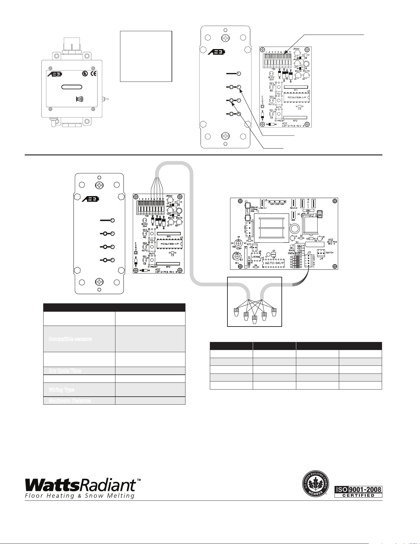
• Remove all power to the sensor and open the cover
• Plug the CS-1 Pigtail into the jack labeled J3 on the snow sensor
circuit board.
• Cut the required length of 5 or 6 conductor, minimum 22 AWG
shielded cable.
• Prepare both ends of the conductor cable by removing 2 inches of
outer jacket and shield, then strip 1/2" of the insulation from
the conductors.
• Attach one end of the conductor cable to the free end of the CS-1
Pigtail inside a weatherproof junction box noting any color code change
in the table.
• Following the color code table, attach the other end of this cable
terminals 5 through 9 of the terminal block labeled TB1 on the PM-DP,
making sure to connect the noted color to the proper terminal.
• Secure the wires to the TB1 connectors by pressing the clamp button
on the terminal block and inserting the bare wire end and then
releasing the button.
• Lightly tug on the wire to endure the wire is securely connected.
• To reduce the chances of damage due to static shock, ground the
PM-DP faceplate by removing 1 inch of insulation from the green EGND
lead and connecting this lead along with the bare "drain" wire, in the
long 5 or 6-conductor 22 AWG shielded cable, to an electrical ground
lead using a wire nut or equivalent.
Home Automation
Use terminals 1-4 on TB1 when connecting to a home automation
system. Closure of terminals 1-2 (Trigger) and 3-4 (Enable) will start one
snow melting cycle. Once the cycle is completed the sensor will revert to
Automatic mode.
Connect a toggle switch to the Enable
terminals to allow manual enabling and
disabling of the home automation system.
If a secondary toggle switch is not used,
jumper terminals 3-4 to allow the home
automation system to enable the system
as needed.
PM-DP fits directly into a single-gang box and
can be fitted with a standard "modular" elec-
trical cover plate. A CS-1 pigtail is included
with the PM-DP.
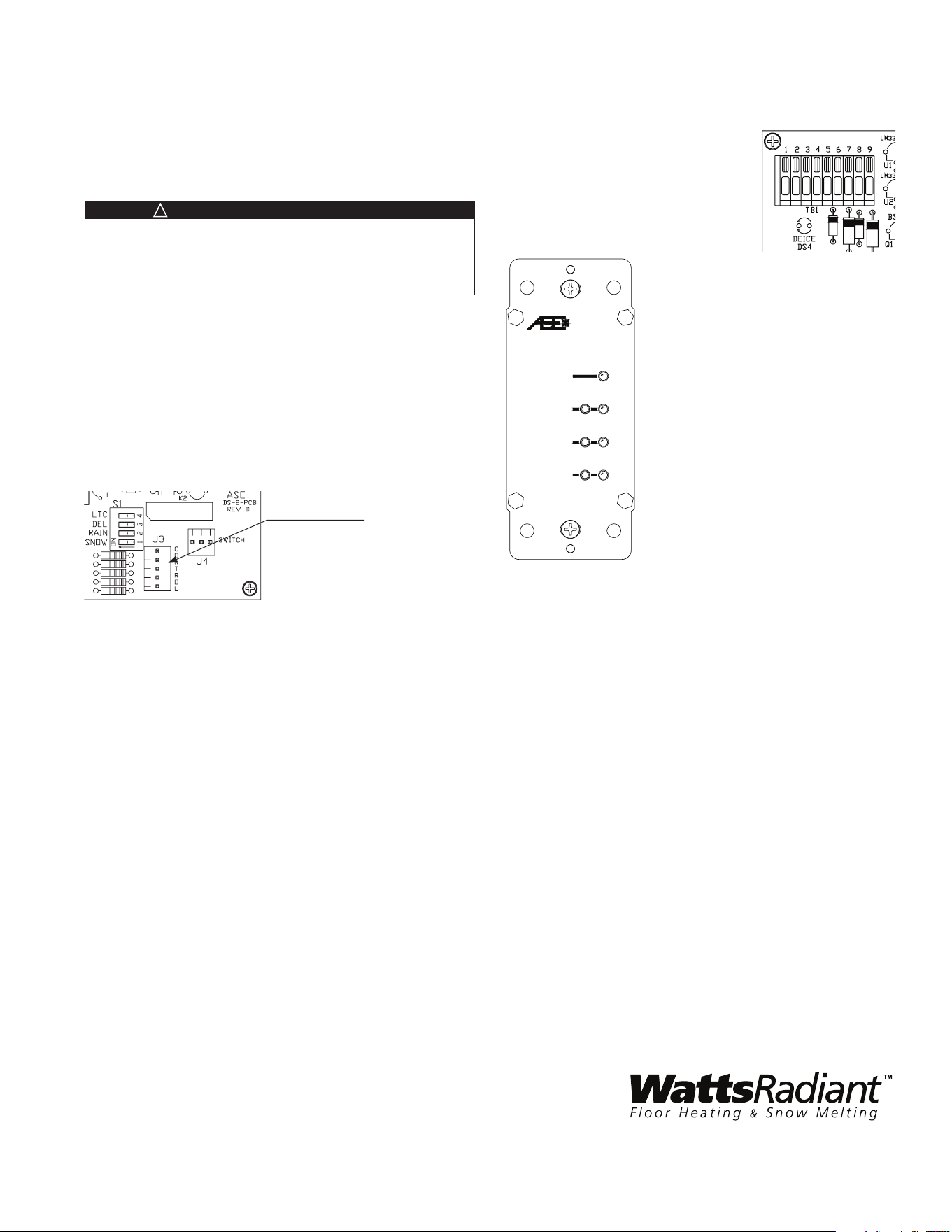
!
WARNING: General Safety Instructions
1. THIS UNIT SHOULD BE INSTALLED ONLY BY
QUALIFIED PERSONNEL!
2. Disconnect all power from the control, or any associated equipment,
before opening the front cover plate.
CDP-2
Deice On
Snow Sensor
Control/Display Panel
Standby
Automatic
Manual On
SYSTEMS
AUTOMATED
ENGINEERING
CDP-2
Deice On
Snow Sensor
Control/Display Panel
Standby
Automatic
Manual On
SYSTEMS
AUTOMATED
ENGINEERING
Manual
On
30Min
45
60
75
90
Control/Monitor Jack
IS-WR-PMDP
Watts Radiant product specifications in U.S. customary units and metric are approximate and are provided for reference only. For precise measurements, please
contact Watts Radiant Technical Service. Watts Radiant reserves the right to change or modify product design, construction, specifications, or materials without
prior notice and without incurring any obligation to make such changes and modifications on Watts Radiant products previously or subsequently sold.
Operation
The LED indicators reflect the current operating mode of the snow sensor
and snow melting system. The LED's blink periodically rather than
remaining steadily illuminated.
• The Deice On indicator shows whether or not the attached snow
sensor has been activated and the snow melt system is operating. It may
illuminate either from automatic activation of the sensor or by the user
pressing the Manual On button.
• Pressing Standby will set the connected snow sensor to ignore snow
fall and prohibit automatic operation of an attached snow melt system.
• Pressing Automatic will set the connected snow sensor to
automatically activate and control an attached snow melt system when
snow is detected.
• Pressing the Manual On button will not trigger the sensor to run
continuously but will initiate one drying cycle. This function allows the
user to run a cycle without having to remember to shut the system off.
At the end of the drying cycle the system will revert to Automatic mode,
ready for detection. The user may reset and clear the drying cycle by
pressing Standby. Typically a drying cycle time is configured on the snow
sensor with a delay of 30-90 minutes. It begins once snow stops falling
and allows the heated surface to more thoroughly dry.
The PM-DP will display the current setting of the manual override switch
for the attached snow sensor. The sensor's override switch will always take
precedence over the PM-DP setting. For example, if the PM-DP has placed
the sensor into Standby mode and the sensor switch is moved Manual On,
the PM-DP will show the change to Manual On mode.
Whenever the sensor's switch overrides the PM-DP's setting, then is
returned to Automatic Mode, the PM-DP will revert to the Automatic Mode
as well.
Limited Warranty: Watts Radiant (the “Company”) warrants each product to be free from defects in material and workmanship under normal usage for a period of one year from the date of original shipment. In
the event of such defects within the warranty period, the Company will, at its option, replace or recondition the product without charge.
THE WARRANTY SET FORTH HEREIN IS GIVEN EXPRESSLY AND IS THE ONLY WARRANTY GIVEN BY THE COMPANY WITH RESPECT TO THE PRODUCT. THE COMPANY MAKES NO OTHER WARRANTIES,
EXPRESS OR IMPLIED. THE COMPANY HEREBY SPECIFICALLY DISCLAIMS ALL OTHER WARRANTIES, EXPRESS OR IMPLIED, INCLUDING BUT NOT LIMITED TO THE IMPLIED WARRANTIES OF
MERCHANTABILITY AND FITNESS FOR A PARTICULAR PURPOSE.
The remedy described in the first paragraph of this warranty shall constitute the sole and exclusive remedy for breach of warranty, and the Company shall not be responsible for any incidental, special or consequen-
tial damages, including without limitation, lost profits or the cost of repairing or replacing other property which is damaged if this product does not work properly, other costs resulting from labor charges, delays,
vandalism, negligence, fouling caused by foreign material, damage from adverse water conditions, chemical, or any other circumstances over which the Company has no control. This warranty shall be invalidated
by any abuse, misuse, misapplication, improper installation or improper maintenance or alteration of the product.
Some States do not allow limitations on how long an implied warranty lasts, and some States do not allow the exclusion or limitation of incidental or consequential damages. Therefore the above limitations may not
apply to you. This Limited Warranty gives you specific legal rights, and you may have other rights that vary from State to State. You should consult applicable state laws to determine your rights. SO FAR AS IS
CONSISTENT WITH APPLICABLE STATE LAW, ANY IMPLIED WARRANTIES THAT MAY NOT BE DISCLAIMED, INCLUDING THE IMPLIED WARRANTIES OF MERCHANTABILITY AND FITNESS FOR A PARTICULAR
PURPOSE, ARE LIMITED IN DURATION TO ONE YEAR FROM THE DATE OF ORIGINAL SHIPMENT.
Specifications
Supply Voltage
Class 2
(Derived from Snow Sensor)
Compatible sensors
PM-2B
PM-5
PM-224
PM-824
Operating Temperature
Range
-40ºF to 185ºF
Dry Cycle Time Based on Sensor Setting
Location Used Indoor
Wiring Type
22 AWG (minimum)
5 or 6 conductor
Maximum Distance 800 ft.
CDP-2
Deice On
Snow Sensor
Control/Display Panel
Standby
Automatic
Manual On
SYSTEMS
AUTOMATED
ENGINEERING
Manual
On
30Min
45
60
75
90
Junction
Box
Waterproof
22 AWG
Shielded
5 or 6
Conductor
Cable
The PM DP snow melt
sensor remote control is
compatible with PM-2B,
PM-5, PM-224, and
PM-824 snow controls.
See submittal or
installation instructions
for more information.
CDP-2
Deice On
Snow Sensor
Control/Display Panel
Standby
Automatic
Manual On
SYSTEMS
AUTOMATED
ENGINEERING
IND. CONT. EQ.
LISTED
11TN
USC
R
ENCLOSURE TYPE 3R
�
�
LED Indicator
Switch
Home Automation Interface
EDP# 81012453
CS-1 Color Function Field Color PM-DP Terminal
Black Manual On 5
White Return 6
Green Standby/Reset 7
Orange Deice On 8
Red Deice On 9
IS-WR-PMDP 1233 © 2012 Watts Radiant
USA: Springfield, MO • Tel. (800) 276-2419 • Fax: (417) 864-8161 • www.wattsradiant.com
Canada: Burlington, ONT. • Tel. (905) 332-4090 • Fax: (905) 332-7068 • www.watts.ca
A Watts Water Technologies Company
