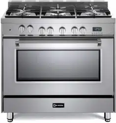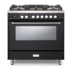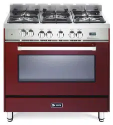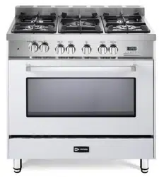
SINGLE OVEN DUAL FUEL RANGE
Models: VPRFSGE365..
INSTALLATION INSTRUCTIONS
IMPORTANT - PLEASE READ AND FOLLOW
• Before beginning, please read these instructions completely and carefully.
• Do not remove permanently affixed labels, warnings, or plates from the product. This may
void the warranty.
• Please observe all local and national codes and ordinances.
• Please ensure that this product is properly grounded.
• The installer should leave these instructions with the consumer who should retain
for local inspector’s use and for future reference.
• IN CANADA: The electrical plug should always be accessible.
Installation must conform with local codes or in the absence of codes, the National Fuel Gas
Code ANSI Z223.1/NFPA 54 - Iatest edition. Electrical installation must be in accordance
with the National Electrical Code, ANSI/NFPA70 - latest edition and/or local codes. IN
CANADA: Installation must be in accordance with the current CAN/CGA-B149.1 National
Gas Installation Code or CAN/CGA-B149.2, Propane Installation Code and/or local codes.
Electrical installation must be in accordance with the current CSA C22.1 Canadian Electrical
Codes Part 1 and/or local codes.
INSTALLATION IN MANUFACTURED (MOBILE) HOME: The installation must conform
with the Manufactured Home Construction and Safety Standard, Title 24 CFR, Part 3280
[formerly the Federal Standard for Mobile Home Construction and Safety, Title 24, HUD
(Part 280)] or, when such standard is not applicable, the Standard for Manufactured Home
Installations, ANSI/NCSBCS A225.1, or with local codes where applicable.
INSTALLATION IN RECREATIONAL PARK TRAILERS: The installation must conform with
state or other codes or, in the absence of such codes, with the Standard for Recreational
Park Trailers, ANSI A119.5.
Installation of any gas-fired equipment should be made by a Iicensed plumber. A manual
shut-off valve must be installed in an accessible location in the gas line external to the
appliance for the purpose of turning on or shutting off gas to the appliance (In Massachusetts
such shutoff devices should be approved by the Board of State Examiners of Plumbers &
Gas Fitters).
If an external electrical source is utilized, the appliance, when installed, must be electrically
grounded in accordance with local codes or, in the absence of local codes, with the national
Electrical Code, ANSI/NFPA 70.
FOR INSTALLER ONLY
THIS RANGE IS FOR RESIDENTIAL USE ONLY
Some models are supplied with a protective lm on steel and aluminum parts.
This lm must be removed before installing/using the appliance.
22
– Do not store or use gasoline or other ammable vapors and
liquids in the vicinity of this or any other appliance.
– NEVER use this appliance as a space heater to heat or
warm the room. Doing so may result in carbon monoxide
poisoning and overheating of the appliance.
– WHAT TO DO IF YOU SMELL GAS:
• Do not try to light any appliance.
• Do not touch any electrical switch.
• Do not use any phone in your building.
• lmmediately call your gas supplier from a neighbor’s
phone. Follow the gas supplier’s instructions.
• lf you cannot reach your gas supplier, call the re
department.
– Installation and service must be performed by a qualied
installer, service agency, or the gas supplier.
If the information in this manual is not followed exactly,
a re or explosion may result causing property damage,
personal injury, or death.
WARNING!
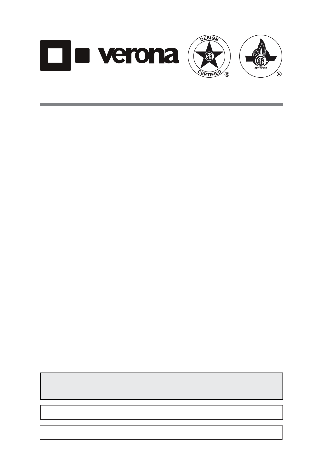
WARNING
- Slide range back so bolt head, on the adjustable bracket assembly, is
--under anti-tip bracket.
- Look for the anti-tip bracket securely attached to oor or wall.
- See installation instructions for details.
- Look for the adjustable bracket assembly securely attached to
--the back of the range.
- Slide range forward.
To verify the anti-tip bracket is installed and engaged:
Tip-Over Hazard
Anti-tip bracket
Adjustable bracket
assembly to be xed to
the back of the range
A child or adult can tip the range and be killed.
Install anti-tip device to range and/or structure per installation
instructions.
Engage the range to the anti-tip device Installed to the structure.
Re-engage anti-tip device if range is moved.
Failure to follow these instructions can result in death or serious
burns to children and adults.
33
This appliance is designed and manufactured solely for the cooking of domestic (household)
food and is not suitable for any non-domestic application and therefore should not be used in a
commercial environment.
The appliance warranty will be void if the appliance is used within a non-domestic environment i.e.
a semi commercial, commercial or communal environment.
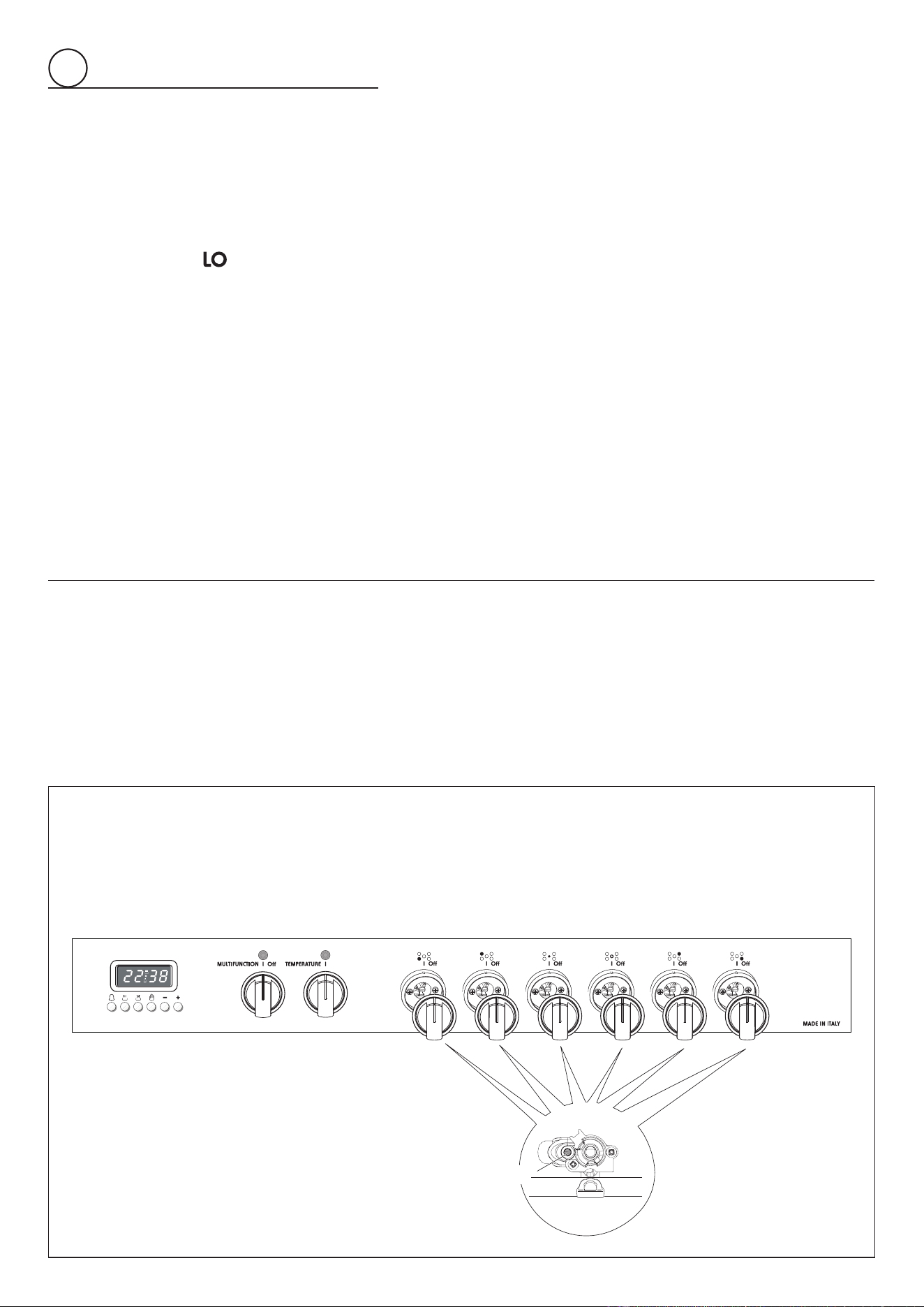
CONVERSION LABEL
DATA PLATE
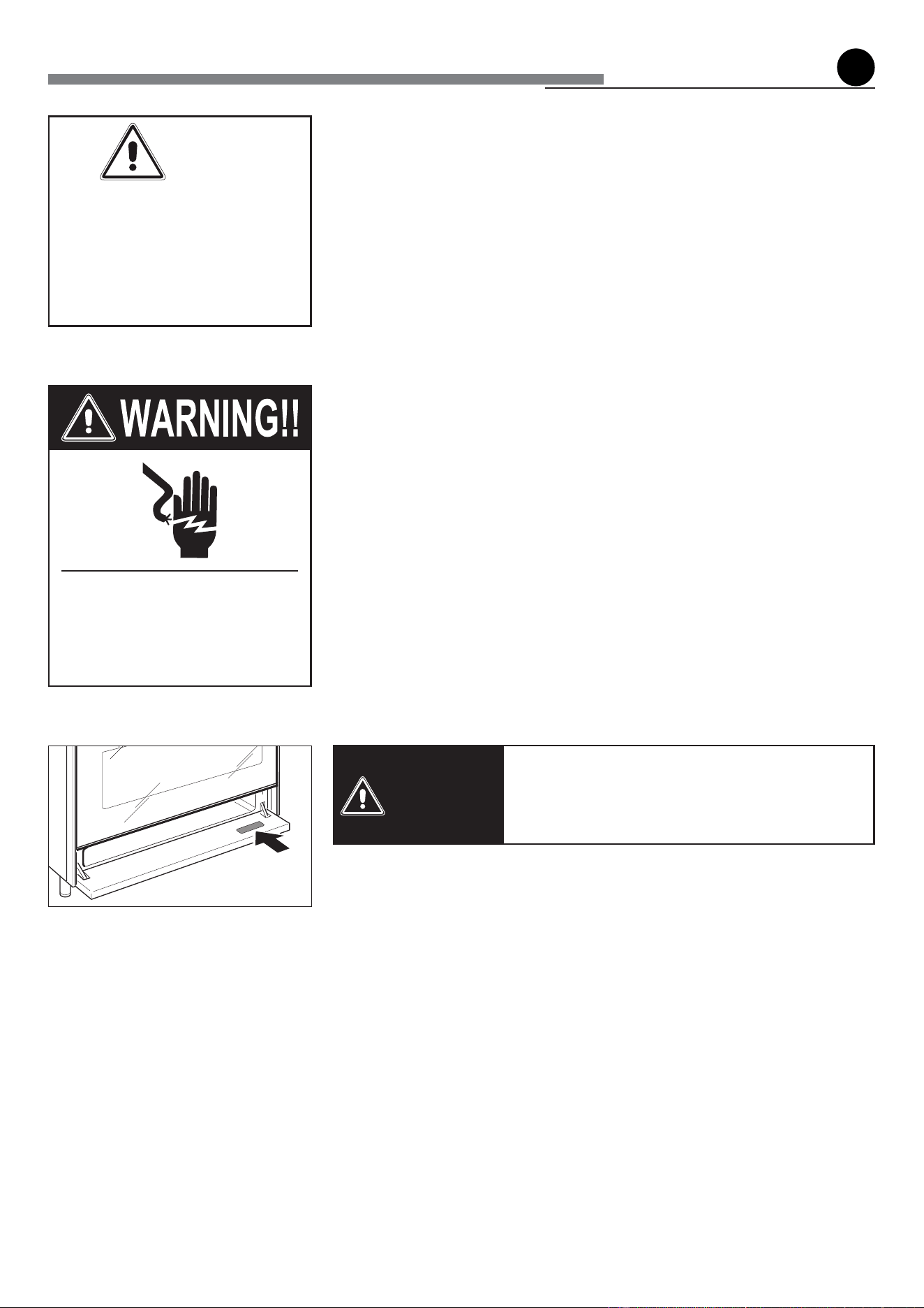
The product data plate is
attached below the bottom
drawer. To check the label,
it is necessary to remove
the drawer (see “Setting
the pressure regulator”
for instructions on drawer
removal).
WARNING: This product can expose you to chemicals including
formaldehyde, which is known to the State of California to cause cancer,
and lead, which is known to the State of California to cause birth defects or other
reproductive harm. For more information go to www. P65Warnings.ca.gov.
44
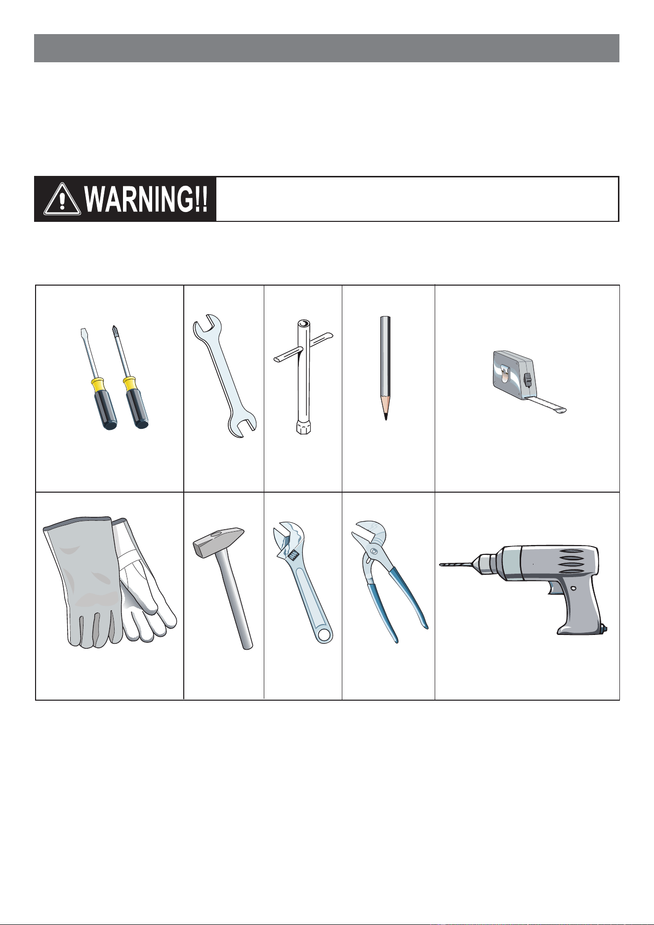
INSTALLATION INSTRUCTIONS
Screwdriver 2 - Wrench
T-handle
wrench
Tape
measurePencil
Adjustable
pliers
Adjustable
wrench
Suitable protective
gloves
Drill
Hammer
TOOLS NEEDED FOR INSTALLATION (NOT SUPPLIED WITH THE APPLIANCE)
IMPORTANT: The use of suitable protective clothing/gloves is
recommended when handling or installing this appliance.
WARNING!
THIS APPLIANCE MUST BE INSTALLED BY A QUALIFIED INSTALLER.
Installation must conform with local codes.
Improper installation, adjustment, alteration, services, or maintenance can cause injury or property damage.
Consult a qualied installer, service agent or the gas supplier.
55
WARNING!!
ELECTRICAL GROUNDING INSTRUCTIONS
The range must be electrically grounded in accordance with
local codes or, in the absence of local codes, with the National
Electrical Code, ANSI/NFPA No. 70-latest edition, in Canada
Canadian Electrical Code.
Installation should be made by a Iicensed electrician.
FOR PERSONAL SAFETY, THIS APPLIANCE MUST BE
PROPERLY GROUNDED.
If an external electrical source is utilized, the installation must be
electrically grounded in accordance with local codes or, in the
absence of local codes, with the national Electrical Code, ANSI/
NFPA 70.
IN CANADA: This appliance is equipped with a four-prong
grounding plug (NEMA 14-50P) for your protection against shock
hazard and should be plugged directly into a properly grounded
socket.
Do not under any circumstances cut or remove the fourth
(ground) prong from the power plug.
REPLACEMENT PARTS
Only authorized replacement parts may be used in performing
service on the range. Replacement parts are available from factory
authorized parts distributors. Contact the nearest parts distributor
in your area.
GENERAL INFORMATION
1. Installation must conform with local codes or, in the absence
of local codes, with the National Fuel Gas Code, ANSI
Z223.1/NFPA 54
- Latest Edition, CAN/CGA-B149.1 or CAN/
CGA-B149.2.
2. Installation in manufactured (mobile) home: installation must
conform with the Manufactured Home Construction and
Safety Standard, Title 24 CFR, Part 3280 [formerly the
Federal Standard for Mobile Home Construction and
Safety, Title 24, HUD (Part 280)] or, when such standard
is not applicable, the Standard for Manufactured Home
Installations, ANSI/NCSBCS A225.1, or with local codes
where applicable.
3. Installation in Recreational Park Trailers: installation must
conform with state or other codes or, in the absence of such
codes, with the Standard for Recreational Park Trailers,
ANSI A119.5.
4. To eliminate risk of burns or re by reaching over heated
surface units, cabinet storage located above the surface units
should be avoided.
5. Air curtain or other overhead range hoods, which operate
by blowing a downward air ow on to a range, shall not be
used in conjunction with gas ranges other than when the
hood and range have been designed, tested and listed by an
independent test laboratory for use in combination.
6. WARNING!!
This appliance shall not be used for space heating. This
information is based on safety considerations.
7. AlI openings in the wall behind the appliance and in the oor
under the appliance shall be sealed.
8. Keep appliance area clear and free from combustible
materials, gasoline, and other ammable vapors.
9. Do not obstruct the ow of combustion and ventilation air.
10. Disconnect the electrical supply to the appliance before
servicing.
11. When removing appliance for cleaning and/or service;
A. Shut o gas at main supply.
B. Disconnect AC power supply.
C. Disconnect gas line to the inlet pipe.
D. Carefully remove the range by pulling outward.
CAUTION: Range is heavy; use care in handling.
12. Electrical Requirement
Electrical installation should comply with national and local
codes.
13. Air Supply and Ventilation
The installer must refer to local/national codes.
14. Gas Manifold Pressure
Natural gas - 4.0” W.C.P.
LP/Propane - 11.0” W.C.P.
15. The misuse of oven door (e.g. stepping, sitting, or leaning on
them) can result in potential hazards and/or injuries.
16. When installing or removing the range for service, a rolling lift
jack should be used. Do not push against any of the edges of
the range in an attempt to slide it into or out of the installation.
Pushing or pulling a range (rather than using a lift jack) also
increases the possibility of bending the leg spindles or the
internal coupling connectors.
66
installation
1
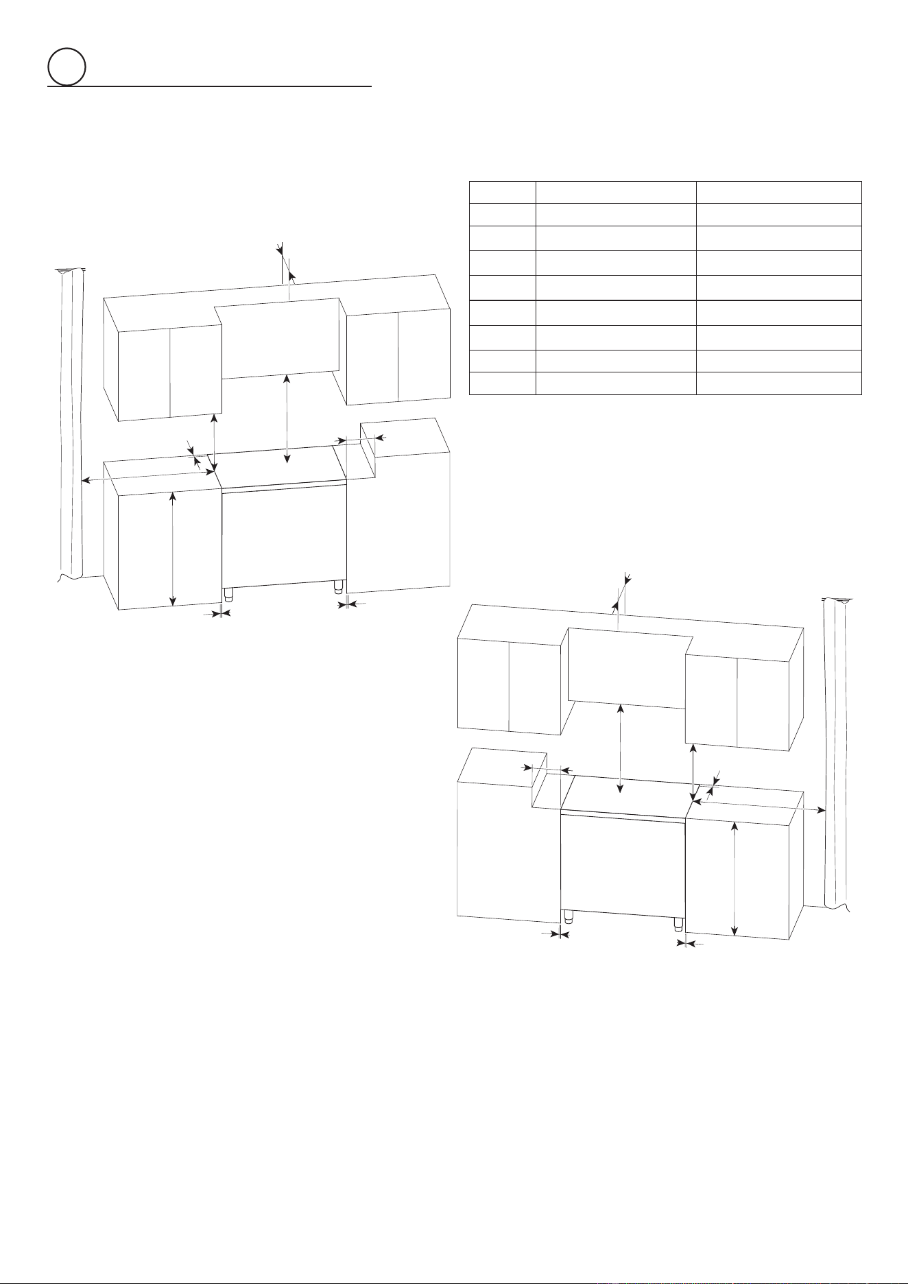
PROXIMITY TO SIDE CABINETS
1. This range may be installed directly adjacent to existing 36”
(914 mm) high base cabinets.
Range dimensions:
• width: 35 7/8” (911 mm) (width of cabinetry opening 36”,
914 mm)
• depth: 25” 1/4 (641 mm)
• height (without backguard): MIN 35” 3/8 (898 mm) - MAX
37” 1/4 (946 mm)
• backguard (height): 3” (76 mm)
• island trim (height): level with cooktop
NOTE: The island trim is supplied with the appliance
while the backguard can be purchased as a separate kit.
Gas line opening: Wall - 1/4” (6 mm) from the right side for
23” 9/16 (599 mm) towards the center of range; from 8” 1/8
(207 mm) to 10” 1/8 (257 mm) [depending on feet regulation]
from the oor.
Grounded outlet: The grounded outlet should be located
1/4” (6 mm) from the left side for 11” 13/16 (300 mm) towards
the center of range; from 8” 1/8 (207 mm) to 10” 1/8 (257
mm) [depending on feet regulation] from the oor.
IN CANADA: The electric cord with 4-prong ground plug
(NEMA 14-50P) has a length of 72” (1830 mm).
2. Range may be installed with zero clearance adjacent to
(against) combustible construction at the rear and on the
sides below the cooktop. The range CANNOT be installed
directly adjacent to sidewalls, tall cabinets, tall appliances,
or other side vertical surfaces above 37” 1/2 (953 mm) max
height (depending on the height of the feet adjustment).
There must be a minimum of 11” 13/16 (300 mm) side
clearance from the range to such combustible surfaces TO
THE LEFT and TO THE RIGHT above the 36” (914 mm) high
countertop.
3. The maximum upper cabinet depth recommended is 13”
(330 mm). A ventilation hood or a wall cabinet above the
range must be a minimum of 30” (762 mm) or 36” (914 mm)
(see also “Additional information about minimum clearance
from cooking surface to overhead cabinet or ventilation
hood” here below) above the cooking surface, for a width of
minimum 36” (914 mm): it has to be centered with the range.
Side wall cabinets above the range must be a minimum of
18” (457 mm) above the countertop.
4. Air curtain or other overhead range hoods, which operate
by blowing a downward air ow on to a range, shall not be
used in conjunction with gas ranges other than when the
hood and range have been designed, tested and listed by an
independent test laboratory for use in combination.
Additional information about minimum clearance from
cooking surface to overhead cabinet or ventilation hood:
• 36” (914 mm), overhead cabinet centered above the cooktop
(combustible/unprotected) (see also notes #1, #2, #3)
• 30” (762 mm), overhead cabinet centered above the cooktop
(non-combustible/protected) (see also notes #1, #2, #3)
• 30” (762 mm), ventilation hood centered above the cooking
surface (see also notes #4)
Note #1
To eliminate the risk of burns or re by reaching over heated surface
units, cabinet storage space located above the surface units
should be avoided. If cabinet storage is to be provided, the risk can
be reduced by installing a rangehood that projects horizontally a
minimum of 5 “ (127mm) beyond the bottom of the cabinets.
Note #2
36” (914mm) minimum clearance between the top of the cooking
surface and the bottom of an unprotected wood or metal cabinet;
or 30” (762mm) minimum when bottom of wood or metal cabinet
is protected by not less than 1/4” thick ame retardant millboard
covered with not less than No. 28 MSG sheet steel, 0.015” (0.4
mm) thick stainless steel, 0.024” (0.6 mm) thick aluminum, or
0.020” (0.5 mm) thick copper.
Note #3
Non-combustible surfaces as dened in ‘National Fuel Gas
Code’ (ANSI Z223.1, Current Edition). Clearances from non-
combustible materials are not part of the ANSI Z21.1 scope and
are not certied by CSA.
Note #4
Refer to local/national codes for ventilation requirements.
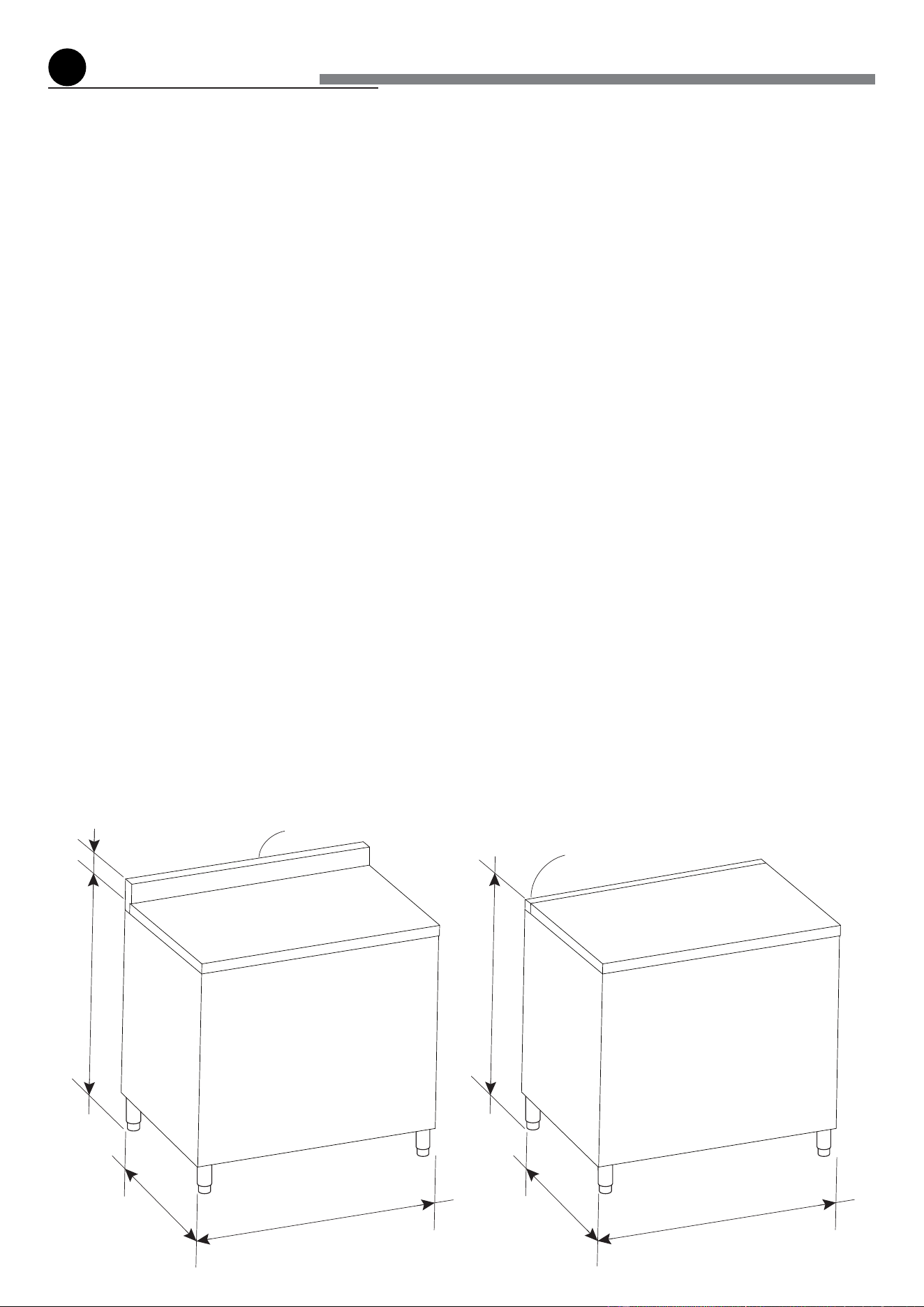
Fig. 1.1a Fig. 1.1b
MIN 35” 3/8 (898 mm)
MAX 37” 1/4 (946 mm)
3” (76 mm)
35” 7/8
(911 mm)
35” 7/8
(911 mm)
Backguard
25” 1/4
(641 mm)
25” 1/4
(641 mm)
MIN 35” 3/8 (898 mm)
MAX 37” 1/4 (946 mm)
Island trim
77
1
ISLAND TRIM AND BACKGUARD
• It is mandatory to install and use the appliance
with either the island trim or the optional 3”
backguard correctly in place.
• The island trim is already tted to the appliance
while the 3” backguard can be purchased as a
separate kit.
• If replacing the island trim with the 3” backguard,
assemble it by using the same screws/spacers
used for xing the island trim (gs. 1.3a, 1.3b).
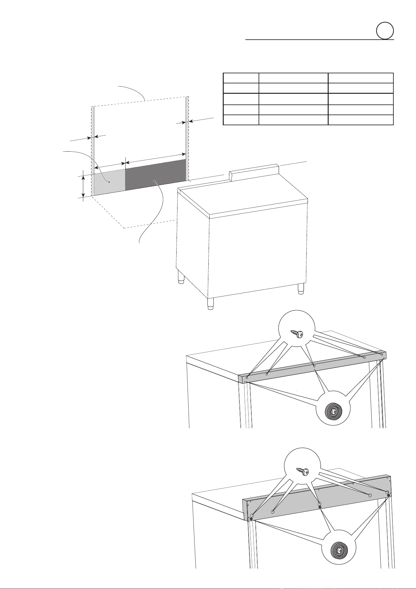
GAS AND ELECTRIC CONNECTION
Fig. 1.2
Dotted line showing the position
of the range when installed
Area for
ELECTRICAL
connection
Area for
GAS connection
A
A
B
D
C
Ref. inch mm
A 1/4” 6
B 23” 9/16 599
C 8” 1/8 - 10” 1/8 (*) 207 - 257 (*)
D 11” 13/16 300
(*): Depending on feet regulation
Fig. 1.3a
Fig. 1.3b
A
B
A
B
ISLAND TRIM
BACKGUARD
88
PROXIMITY TO SIDE CABINETS
1
Fig. 1.4b
Fig. 1.4a
Ref. inch mm
A 0” 0
B 37” 1/2 (*) 953 (*)
C 11” 13/16 300
D 30” or 36” minimum (**) 762 or 914 minimum (**)
E 18” minimum 457 minimum
F 13” maximum 330 maximum
G 20” minimum 500 minimum
H 0” 0
A
C
A
B
G
E
D
F
A
A
B
G
E
D
F
C
H
H
(*) Maximum height of cabinetry immediately adjacent to the
range (from oor to countertop).
Depending on the height of the feet adjustment.
The cooking surface must sit ush or above countertop level.
(**) See also “Additional information about minimum clearance
from cooking surface to overhead cabinet or ventilation
hood” at page no.6.
99
1
Fig. 1.5
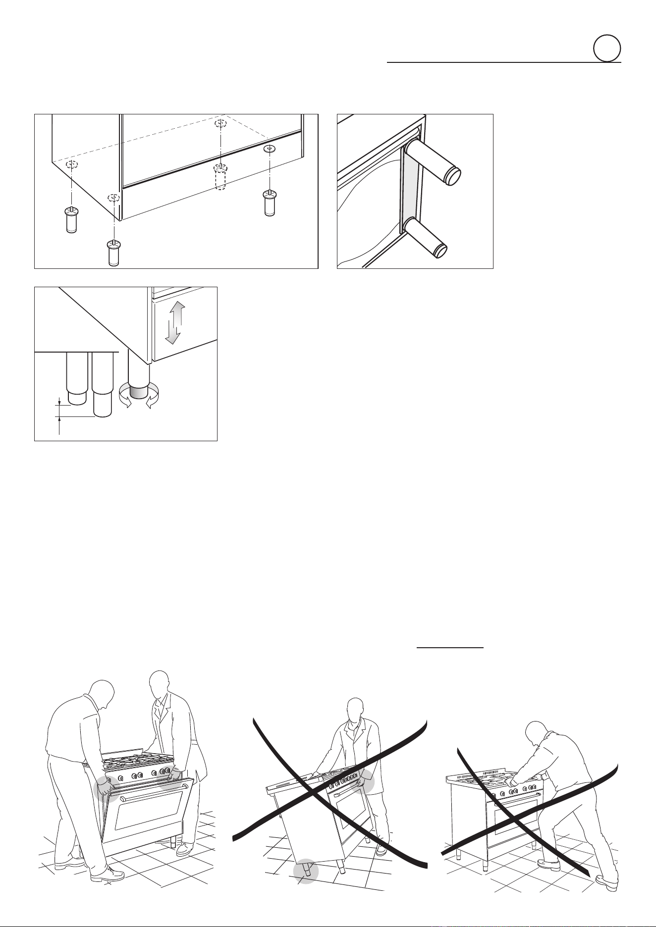
FITTING THE ADJUSTABLE FEET
The adjustable feet must be fitted to the base of the cooker before use.
Rest the rear of the cooker on a piece of the polystyrene packaging exposing the base
for the fitting of the feet.
ATTENTION: Most important! Pay special attention not to damage the range during
this operation.
Fit the 4 legs by screwing them tight into the support base as shown in picture 1.5 - 1.6.
Fig. 1.6
LEVELLING THE COOKER
The cooker may be levelled by screwing the lower ends of the feet IN or OUT (fig. 1.7).
It is important to observe the directions of figure 1.7.
+ 1" 31/32
+ 50 mm
0 mm
0"
Fig. 1.7
MOVING THE COOKER
WARNING
When raising cooker to upright position always ensure two people carry out this
manoeuvre to prevent damage to the adjustable feet (fig. 1.8a).
WARNING
Be careful: do not lift the cooker by the door handle when raising to the upright position
(fig. 1.8b).
WARNING
When moving cooker to its final position
DO NOT DRAG
(fig. 1.8c).
Lift feet clear of floor (fig. 1.8a).
Fig. 1.8a Fig. 1.8b
Fig. 1.8c
1010
1
Fig. 1.10
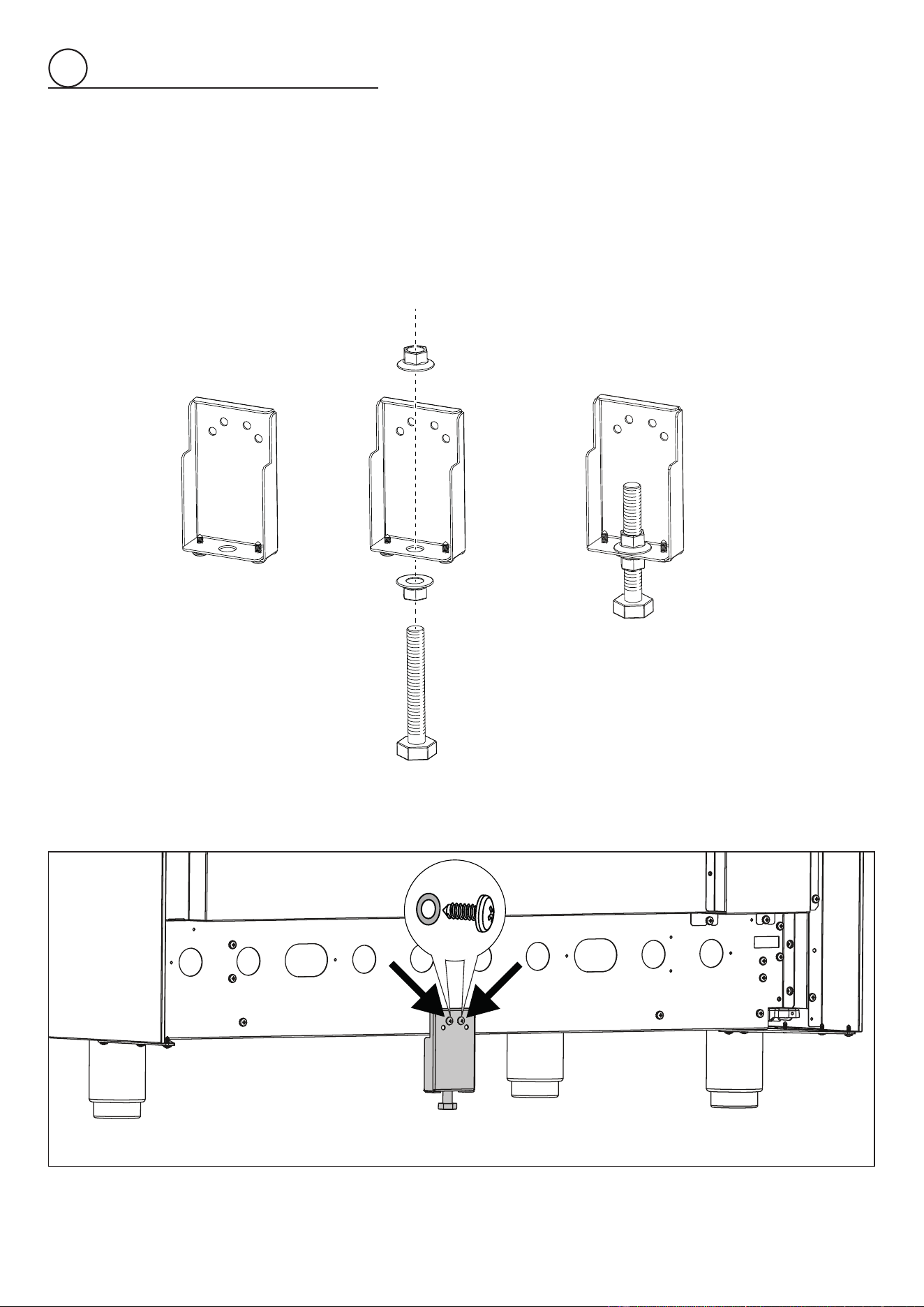
INSTALLING THE ANTI-TIP BRACKET
The anti-tip bracket has two components:
• the adjustable bracket
• the stability bracket
IMPORTANT!
You must install both parts of the anti-tip bracket and ensure they are properly tted together to prevent the range from tipping.
To t the anti-tip bracket
1. Thread the bolt through the adjustable bracket and x in place using the two supplied nuts.
Ensure the nuts are well tightened.
2. Fix the adjustable bracket to the back of the range (centered on the lower edge) using the
two supplied screws and washers.
1 2 3
Fig. 1.9
1111
1
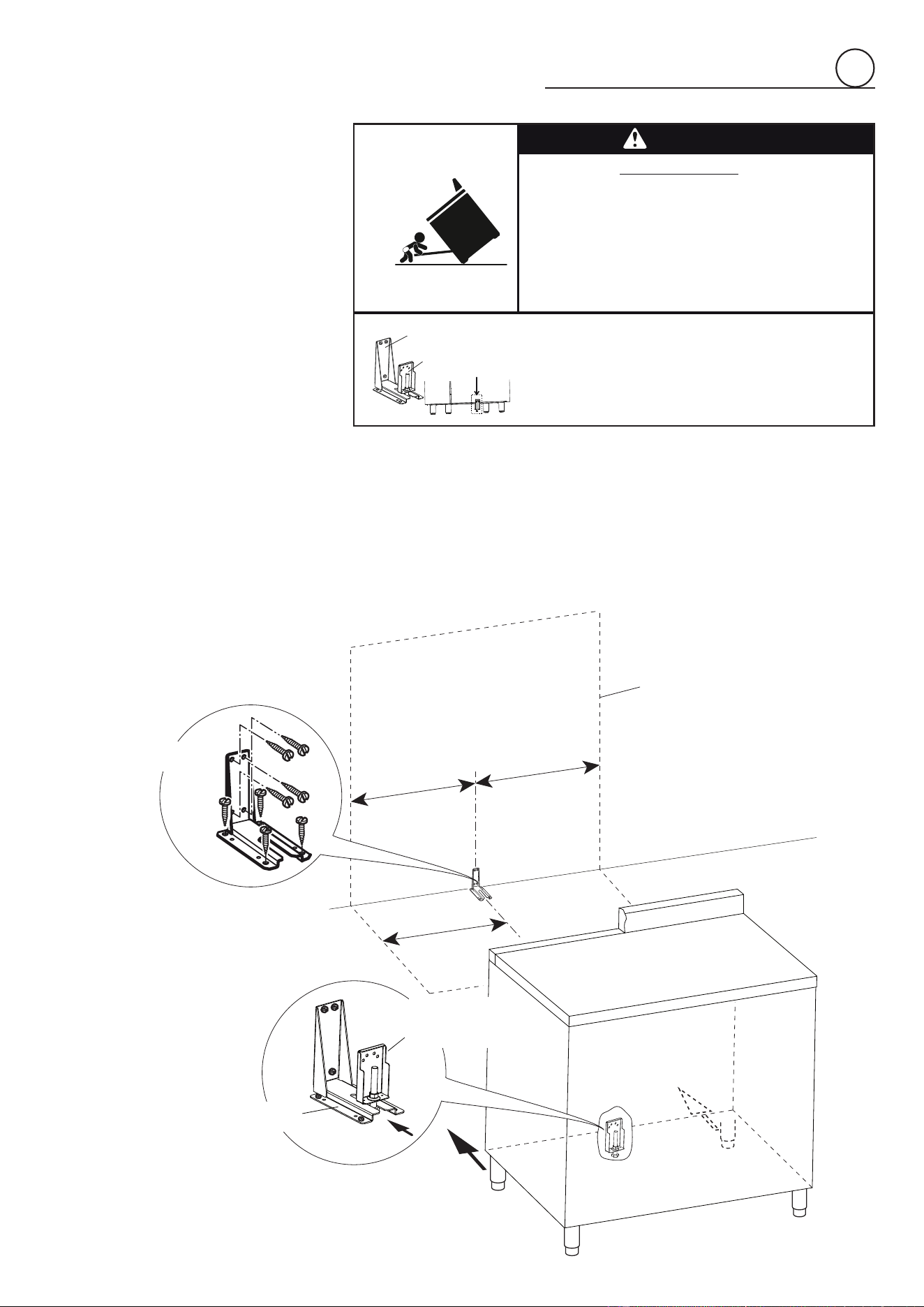
Fig. 1.11
=
=
Dotted line showing the position
of the range when installed
17” 15/16
(455.5 mm)
Anti-tip stability
device
Adjustable
bracket with
threaded nut
correctly tted
Anti-tip stability
device xing
3. Fix the stability bracket in place. It can
be xed as follows:
• To the oor OR on the rear wall by #4
screws (supplied).
• To the oor AND on the rear wall by #8
screws (supplied).
• There are 8 x wood screws and 8 x
screws with plastic sleeve anchors
supplied with the range in two
separate kits.
Use the proper screws according to
the type of material on the oor and/
or wall.
• If using the plastic sleeve anchors: drill
5/16” (8mm) diameter holes and insert
the supplied plastic sleeve anchors before
attaching the stability bracket with the
screws.
4. Slide the range into place, ensuring the
bolt on the adjustable bracket slots under
the stability bracket.
• Adjust the length of the bolt as necessary.
Ensure the two nuts are well tightened
after any adjustments.
IMPORTANT!
• Use the proper screws to x the
stability bracket in place according to
the type of material on the oor and/or
wall.
• Before drilling and holes or inserting
any screws into the oor or wall check
that you will not damage any wiring or
pipes.
WARNING
- Slide range back so bolt head, on the adjustable bracket assembly, is
--under anti-tip bracket.
- Look for the anti-tip bracket securely attached to oor or wall.
- See installation instructions for details.
- Look for the adjustable bracket assembly securely attached to
--the back of the range.
- Slide range forward.
To verify the anti-tip bracket is installed and engaged:
Tip-Over Hazard
Anti-tip bracket
Adjustable bracket
assembly to be xed to
the back of the range
A child or adult can tip the range and be killed.
Install anti-tip device to range and/or structure per installation
instructions.
Engage the range to the anti-tip device Installed to the structure.
Re-engage anti-tip device if range is moved.
Failure to follow these instructions can result in death or serious
burns to children and adults.
1212
1
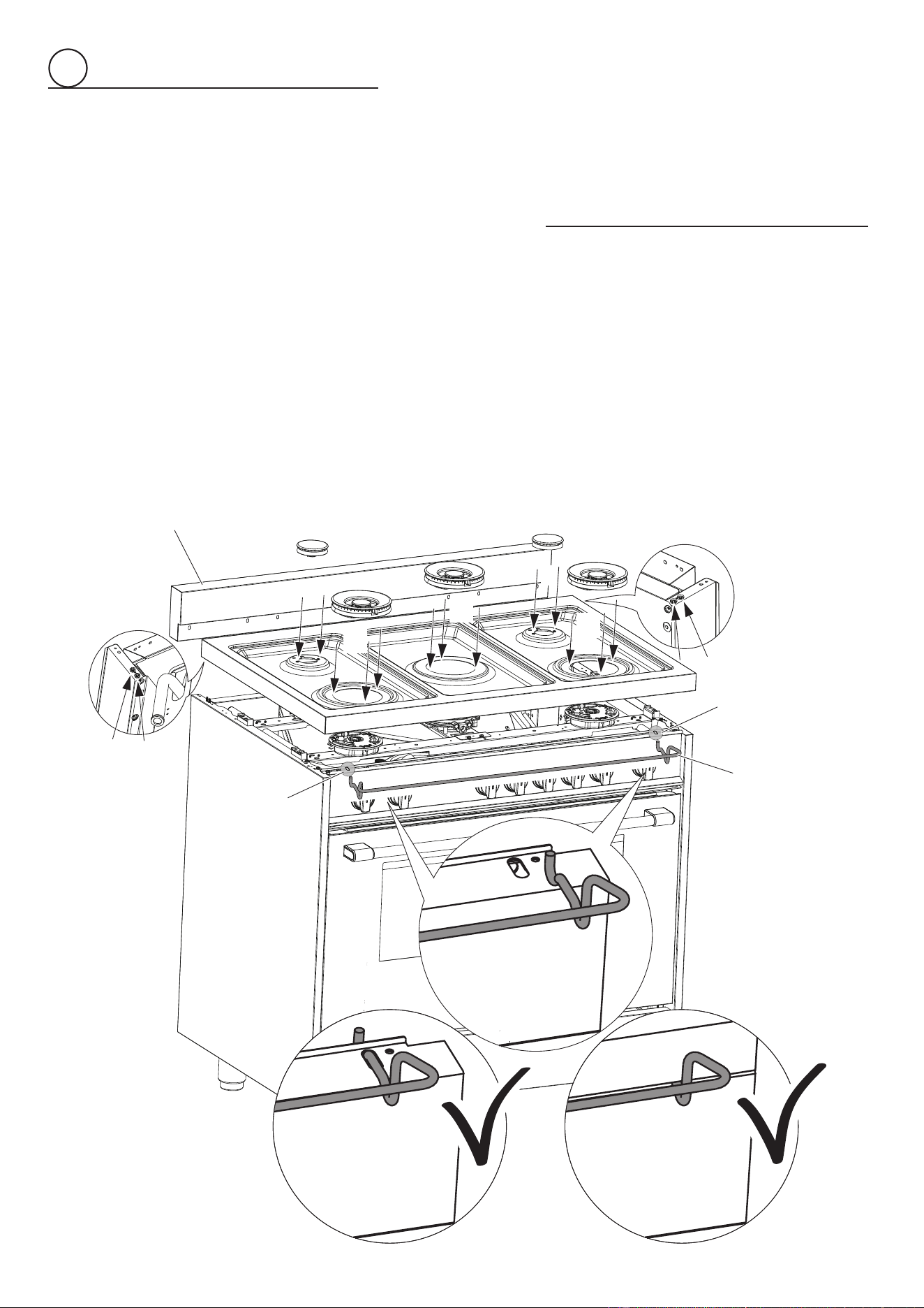
INSTALLING THE COOKTOP FRONT GUARD (Only for the models without hob rail)
To increase the clearance between the front edge of the cooktop and the burners it is possible to install the cooktop front guard supplied
with the appliance.
IMPORTANT: To install/remove the guard it is necessary to remove the cooktop.
Attempting to install/remove the guard without disassembling the cooktop will result in permanent damage to the appliance.
Install the front guard as shown in gure 1.12:
1. Remove the backguard “A”.
2. Remove the pan supports, the burner caps and the ame spreaders.
3. Unscrew cooktop xing screws (“B” and “C” in gure below).
4. Remove the cooktop (keep attention not to damage the gaskets tted above the burner cups - below the cooktop).
5. Install the front guard “D” by inserting the wire terminals into the proper holes above the control panel (“E” in gure below).
6. Reassemble the cooktop and the other components (steps from 4 to 1).
Note: Take extra care not to damage the gaskets tted above the burner cups (below the cooktop). If they are damaged they must
be replaced.
C
C
D
E
E
A
B
Fig. 1.12
B
B
B
B
1313
gas connection
2
2. Pressure Regulator:
a. All heavy duty, commercial type cooking equipment must have a pressure regulator
on the incoming service line for safe and ecient operation, since service pressure
may uctuate with local demand.
Before installing the regulator mount the 1/2” NPT (conical) male connector to the
regulator (see picture 2.2).
Gasket supplied has to be placed between 1/2” NPT (conical) connector/extension
pipe male pipe tting (see picture 2.3).
The regulator supplied with this range must be installed before any gas connections
are made.
Use supplied pressure regulator only.
b. Assemble the extension pipe + pressure regulator group to the range manifold
interposing the gasket supplied (see pictures 2.4, 2.5).
Gas supply line
Shuto valve
“open” position
To range
Explosion Hazard
Use a new CSA or UL approved
gas supply line.
Install a shut-off valve.
Securely tighten all gas connec-
tions.
If connected to LP, have a quali-
fied person make sure gas pres-
sure does not exceed 14" water
column.
Examples of a qualified person
include licensed heating per-
sonnel, authorized gas compa-
ny personnel, and authorized
service personnel.
Failure to do so can result in
death, explosion, or fire.
Fig. 2.1
All gas connections must be made according to national and local codes. This gas supply
(service) line must be the same size or greater than the inlet line of the appliance. Sealant
on all pipe joints must be resistant to the action of LP/Propane gas.
The range is equipped for the use with NATURAL gas. It is design-certied by CSA
International for NATURAL and L.P. gases with appropriate conversion.
The model/serial rating plate, located below the bottom drawer, has information on
the type of gas that can be used. If this information does not agree with the type of
gas available, check with the local gas supplier. See page from 18 to 21 for L.P. gas
conversion instructions.
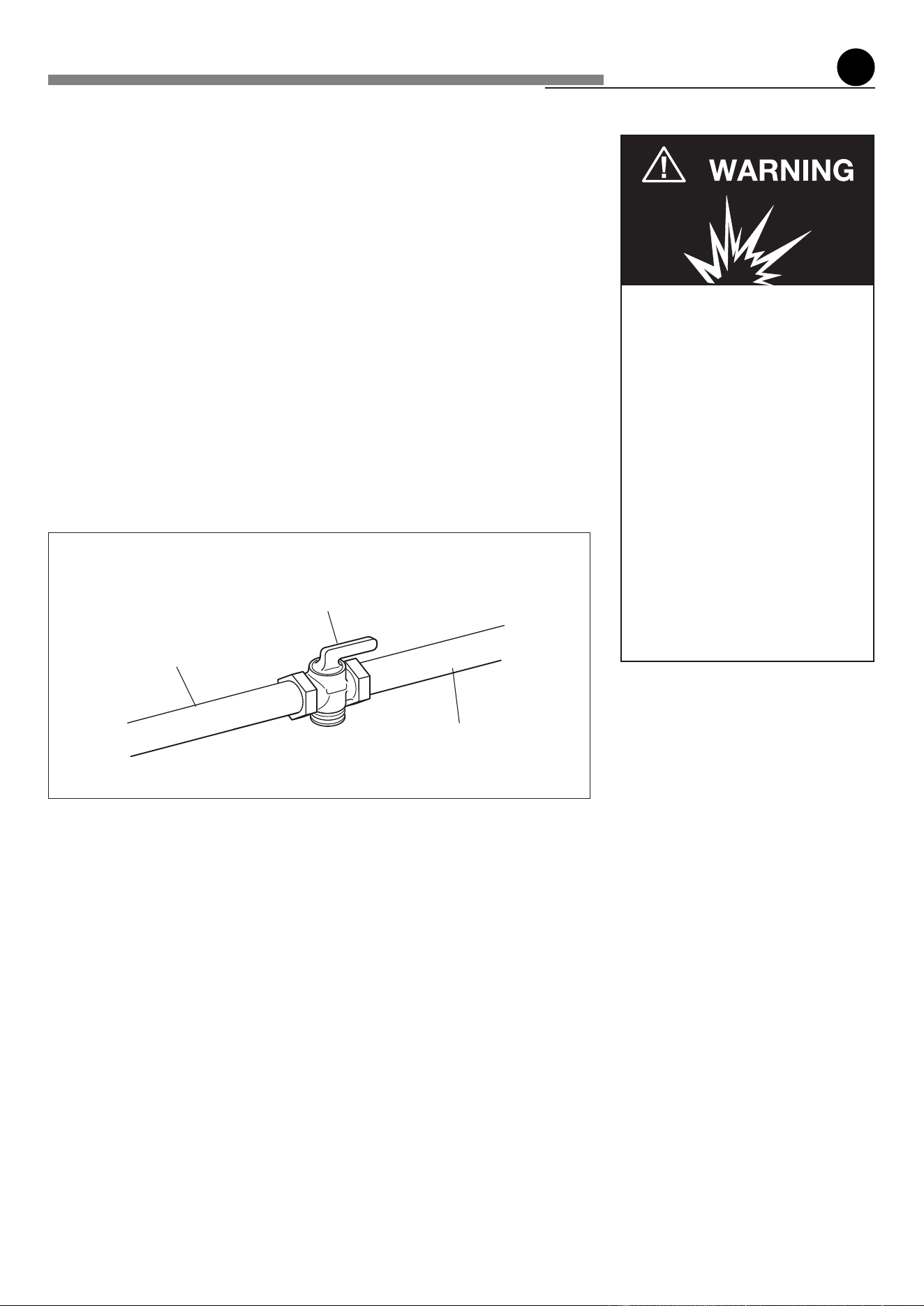
1. Manual Shut-o Valve (g: 2.1):
A manual shut-o valve must be installed in an accessible location in the gas line external
to the appliance for the purpose of turning on or shutting o gas to the appliance (In
Massachusetts such shuto devices should be approved by the Board of State Examiners
of Plumbers & Gas Fitters).
This valve should be located in the same room as the range and should be in a location
that allows ease of opening and closing (in a position where it can be reached quickly in
the event of an emergency).
Do not block access to the shuto valve. The valve is for turning on or shutting o gas
to the appliance.
1414
2
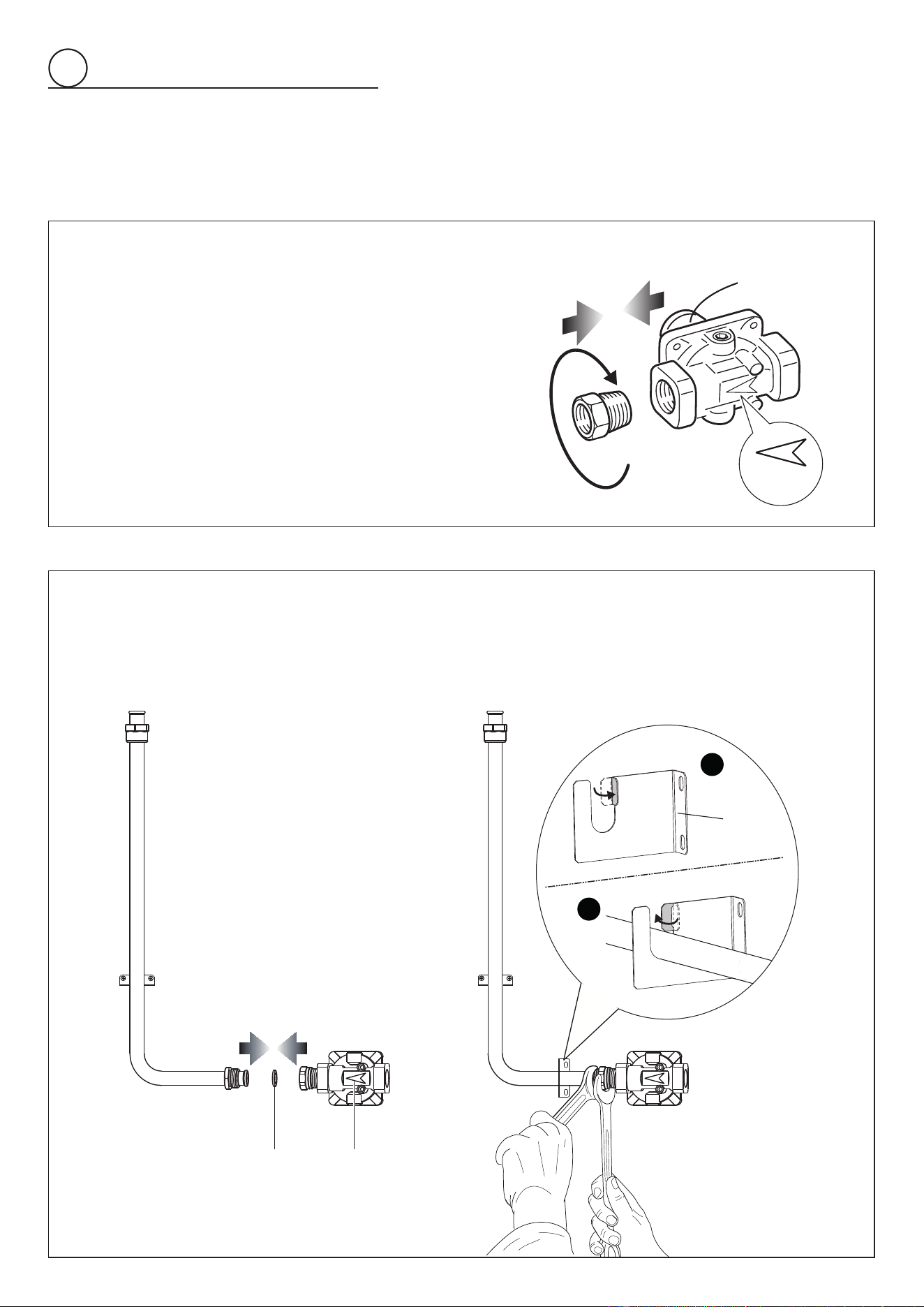
PRESSURE REGULATOR INSTALLATION
STEP 1
Mount the 1/2” NPT (conical) male connector to the pressure regulator and
tighten by using a wrench.
Do not over tighten the connector.
Over tightening may crack regulator.
STEP 2
Assemble the 1/2” NPT connector + pressure regulator group to the extension pipe interposing the gasket supplied.
The regulator cover must be oriented toward the front side of the range.
IMPORTANT: use two wrenches to tighten the connection.
Insert the extension pipe into the supplied support bracket “B” as shown:
• bend in the metal tab 90 degrees to allow the pipe to be tted into the bracket (detail #1);
• bend the metal tab back into its original position to secure (detail #2).
Fig. 2.3
Fig. 2.2
Arrow
Regulator cover
Lock
90°
2
1
90°
Gasket Arrow
B
1515
2
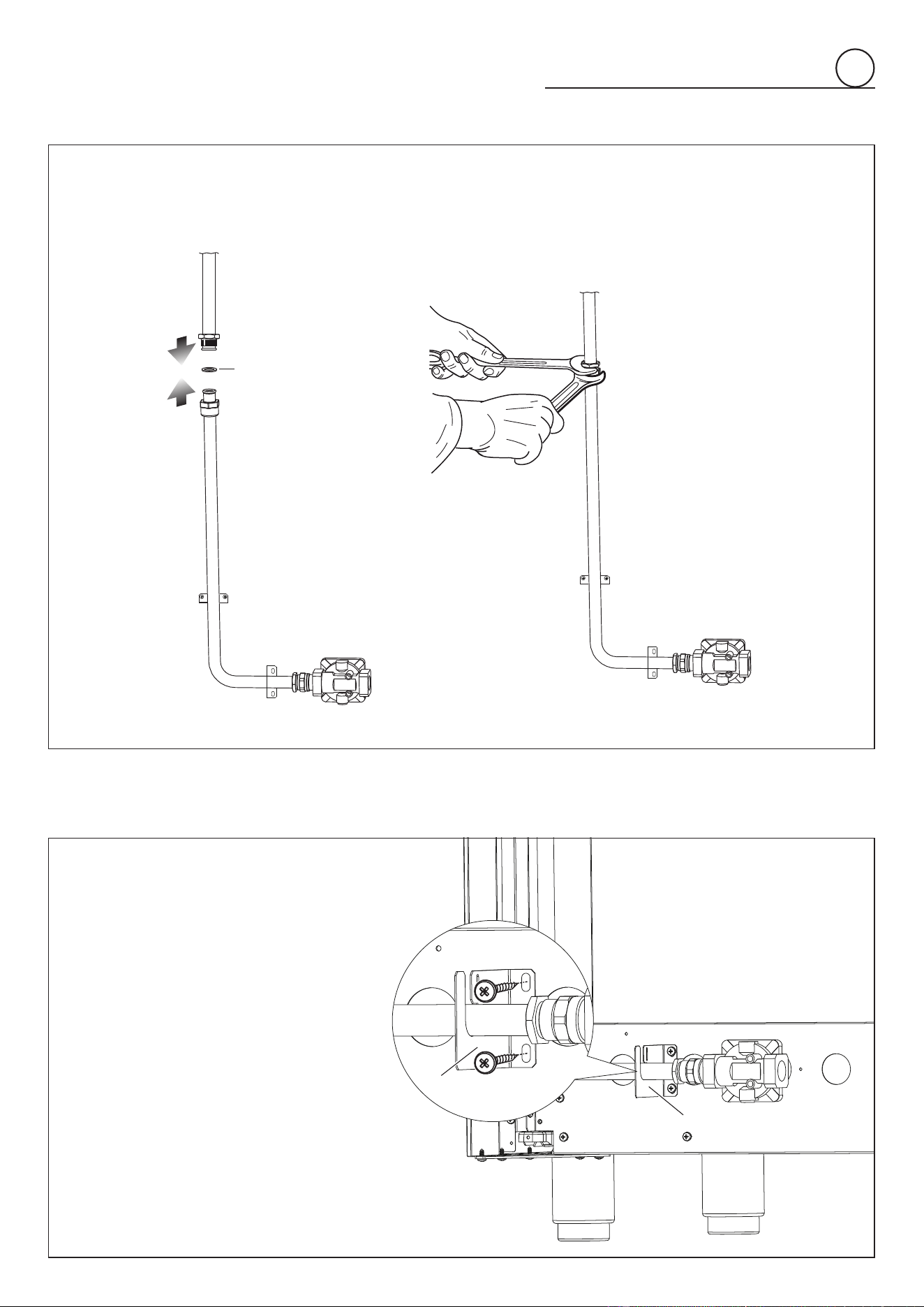
STEP 3
Assemble the extension pipe + pressure regulator group to the range manifold interposing the gasket supplied.
The regulator cover must be oriented toward the front side of the range.
IMPORTANT: use two spanners to tighten the connection.
STEP 4
Fix the extension pipe support bracket
onto the back of the range using the two
supplied screws.
Take care to ensure the bracket is tted the
right way up with the opening at the top.
The regulator cover must be oriented
toward the front side of the range.
Fig. 2.4
Fig. 2.5
B
B
Gasket
1616
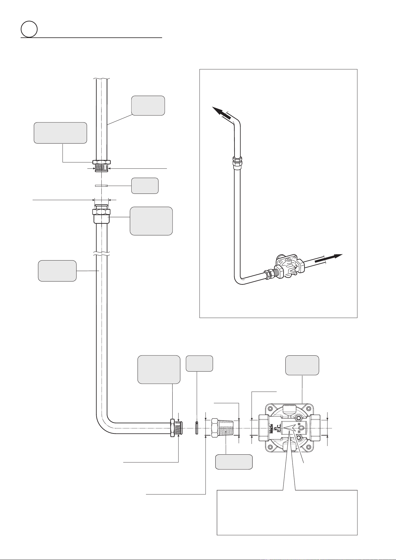
GAS CONNECTION SPECIFICATION
Connector
Pressure
regulator
1/2” G cylindrical
(ISO 228-1) female
1/2” NPT
(conical)
male
1/2” NPT
female
1/2” NPT
female
1/2” G cylindrical
(ISO 228-1) male
Extension
pipe male
pipe tting
Gasket
Range
manifold
Manifold male
pipe tting
1/2” G cylindrical
(ISO 228-1) male
Extension
pipe female
pipe fitting
1/2” G cylindrical
(ISO 228-1) female
Gasket
Extension
pipe
Extension
pipe female
pipe tting
Arrow
WARNING: check the right
positioning of the gas regulator.
The arrow on the gas regulator must
be oriented toward the connector.
To mains
connection
To range
Fig. 2.6
2
1717
c. Any conversion required must be performed by your dealer or a qualied
licensed technician or gas service company. Please provide the service person
with this manual before work is started on the range. (Gas conversions are the
responsibility of the dealer or end user.)
d. This range can be used with NATURAL or LP/PROPANE gas. It is shipped from
the factory adjusted for use with NATURAL gas.
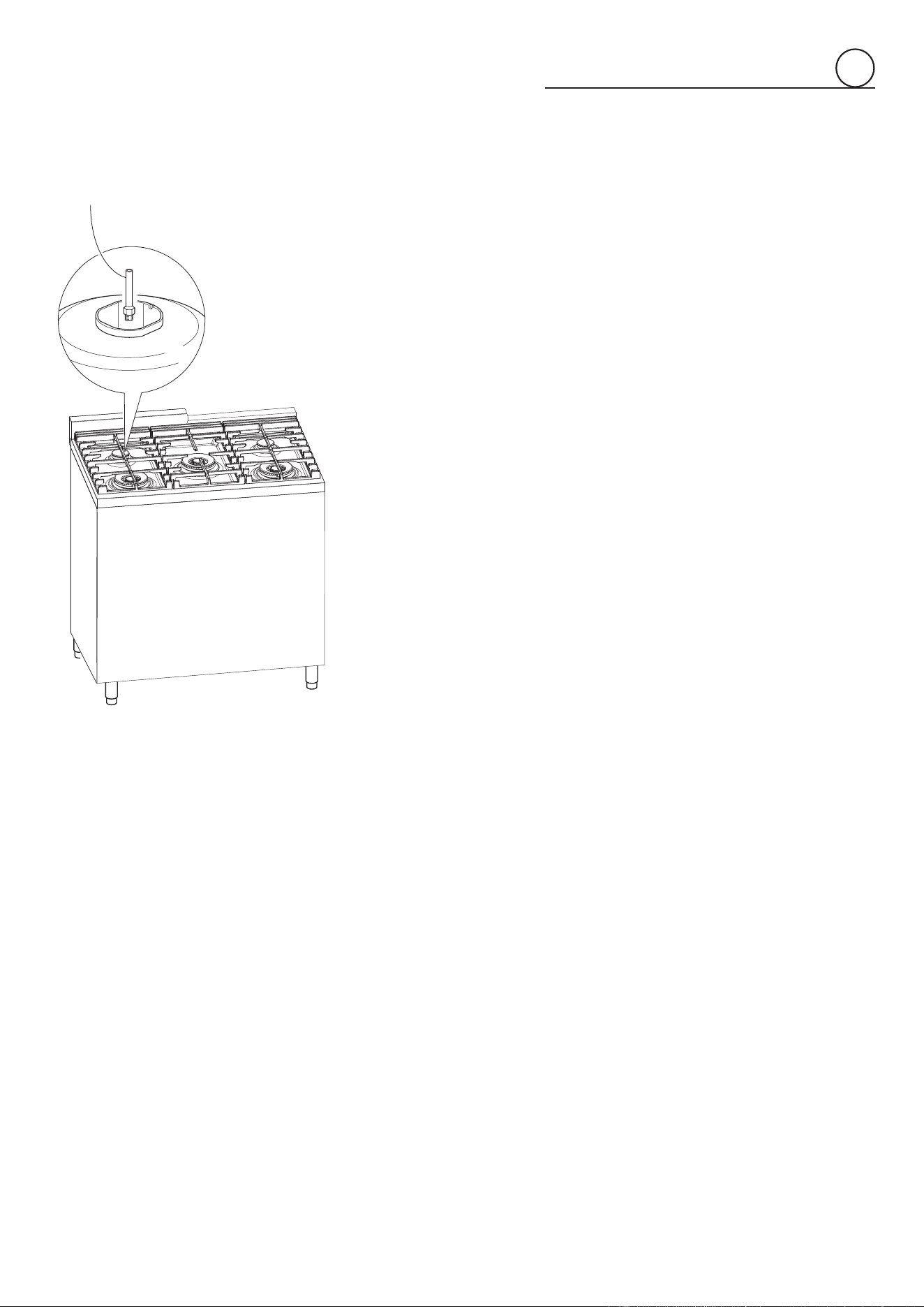
e. Manifold pressure should be checked with a manometer and by operating as
below detailed:
• Remove the injector from the rear left (or rear right) burner and mount the
proper test point adapter which is available from the After-Sales Service
(see side gure and the “
OPERATIONS TO BE PERFORMED WHEN
SUBSTITUTING
THE INJECTORS OF THE COOKTOP BURNERS”
chapter).
• Turn the rear left (or rear right) burner control knob to the maximum position.
• Press the knob and keeping it pressed check the manifold pressure with a
manometer; NATURAL gas requires 4.0” W.C.P. and LP/PROPANE requires
11.0” W.C.P.
• Incoming line pressure upstream from the regulator must be 1” W.C.P.
higher than the manifold pressure in order to check the regulator.
• The regulator used on this range can withstand a maximum input pressure
of 1/2 PSI (14.0” W.C.P). If the line pressure is in excess of that amount, a
stepdown regulator will be required.
f. The appliance, its individual shut-o valve, and pressure regulator must be
disconnected from the gas supply piping system during any pressure testing of
that system at pressures in excess of 1/2 PSI (3.5 kPa).
g. The appliance must be isolated from the gas supply piping system by closing its
individual manual shut-o valve during any pressure testing of the gas supply
piping system at test pressure equal to or less than 1/2 PSI (3.5 kPa).
3. Flexible Connections:
If local codes permit, CSA or UL design-certied, exible metal appliance connector is
recommended for connecting this range to the gas supply line. Do Not kink or damage
the exible connector when moving the range. The pressure regulator has 1/2” NPT
female pipe threads. You will need to determine the ttings required, depending on
the size of your gas supply line, exible metal connector and shuto valve.
4. Rigid Pipe Connections:
If rigid pipe is used as a gas supply line, a combination of pipe ttings must be used to
obtain an in-line connection to the range. All strains must be removed from the supply
and fuel lines so range will be level and in line.
• Use joint compounds and gaskets that are resistant to action of natural or
propane gas on all male pipe threads.
• Do not over tighten gas tting when attaching to pressure regulator. Over
tightening may crack regulator.
5. Leak Testing:
IMPORTANT: Leak testing of the appliance shall be conducted as follows:
• After nal gas connection is made, turn on manual gas valve and test all
connections in gas supply piping and appliance for gas leaks with a soapy water
solution. During this test all appliance gas valves have to be closed.
• In order to avoid property damage or serious personal injury, never use a Iighted
match. If a leak is present, tighten joint or unscrew, apply more joint compound,
tighten again and retest connection for leak.
Fig. 2.7
TEST POINT ADAPTER
The Test Point adapter is available from the
After-Sales Service.
2
1818
2
1
2
NATURAL GAS
REGULATION
LP/PROPANE
REGULATION
A
component
Fig. 2.8
REGULATOR
COVER
Pressure
regulator
CONVERSION TO LP/PROPANE GAS (OR CONVERSION
BACK TO THE ORIGINAL GAS - NATURAL GAS)
Every range is provided with a set of injectors for the various types of gas.
Select the injectors to be replaced according to the “INJECTORS TABLE”.
The nozzle diameters, expressed in hundredths of a millimetre, are marked on the
body of each injector.
CAUTION: Save the orifices removed from the appliance for future use.
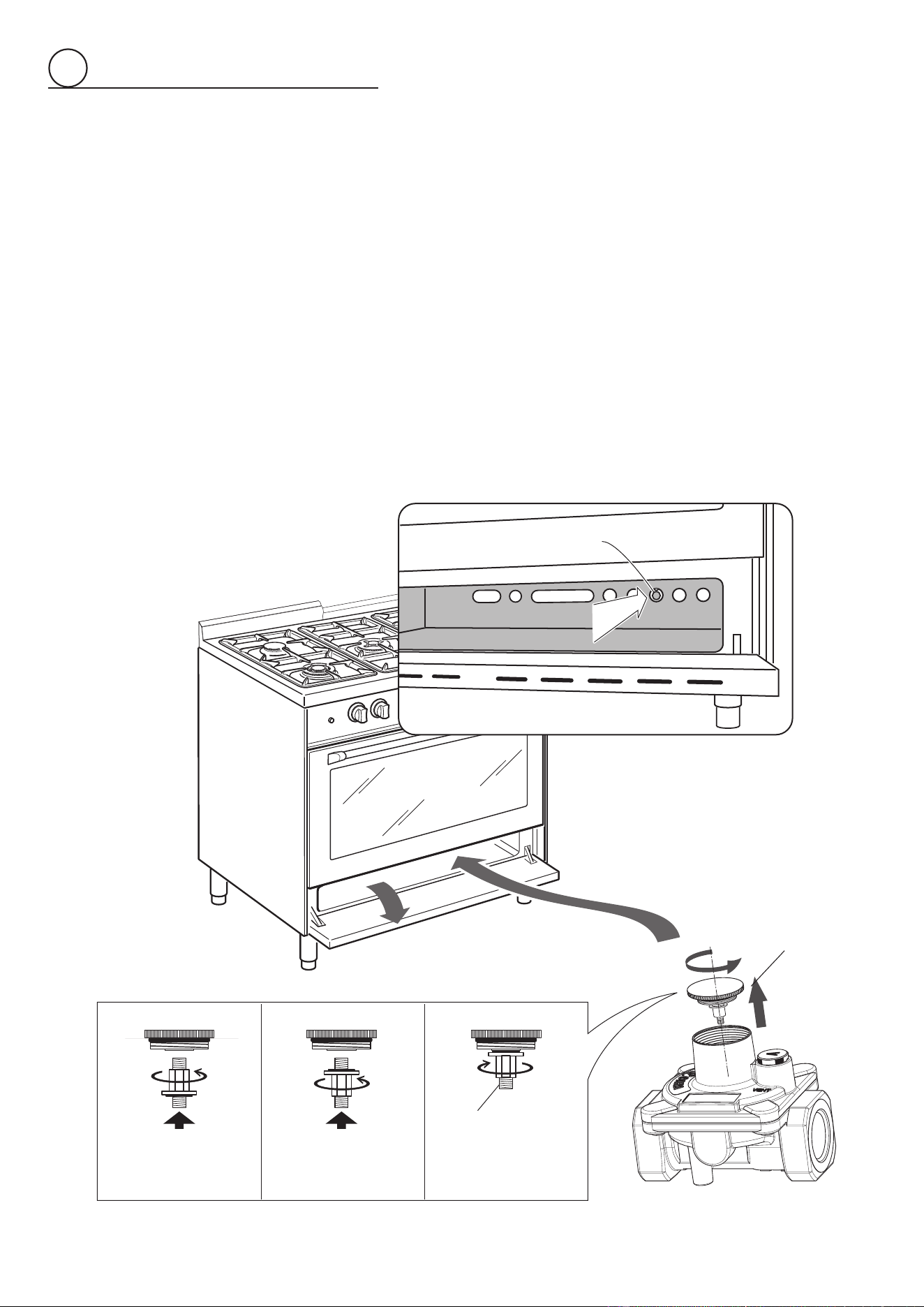
SETTING THE PRESSURE REGULATOR (fig. 2.8)
The pressure regulator is accessible through the storage compartment by opening
the bottom pivoting panel; the pressure regulator is positioned on the rear right side
of the range.
To set the pressure regulator:
1. Unscrew the regulator cover;
2. Unscrew the "
A
" component, reverse and screw it according to the LP/PROPANE (or
NATURAL GAS) regulation.
1919
2
INJECTORS TABLE
NOMINAL
POWER
REDUCED
POWER
LP/PROPANE
11” W.C.P.
NATURAL GAS
4” W.C.P.
BURNERS BTU/hr BTU/hr
Ø injector
[1/100 mm]
Ø injector
[1/100 mm]
Semi-rapid (SR) 8000 1500 82 136
Double-ring compact (DCC) 12000 5000 102 170
Dual (DB)
Inner crown 2800 (
1
) 1100 (
1
) 48 (
3
) 82 (
3
)
Outer crown 14200 (
2
) 5000 (
2
) 112 (
4
) 190 (
4
)
(
1
) Power calculated only with inner crown operating
(
2
) Power calculated only with outer crown operating
(
3
) inner crown (“J
3
” in gure 2.11)
(
4
) outer crown (“J
4
” in gure 2.11)
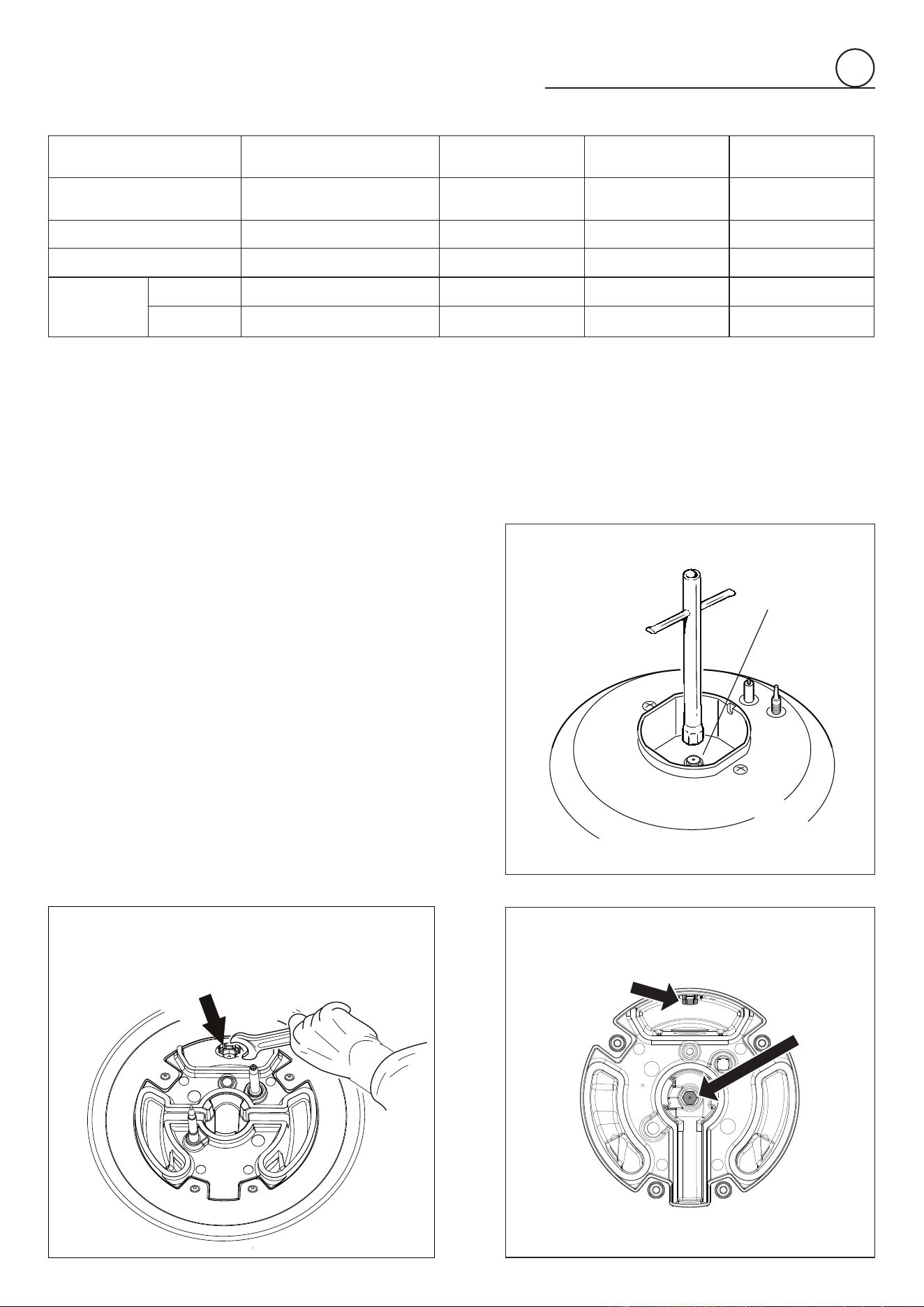
OPERATIONS TO BE PERFORMED WHEN
SUBSTITUTING THE INJECTORS OF THE
COOKTOP BURNERS
To replace the injectors proceed as follows:
• Remove pan supports and burners from the cooktop.
• Using a wrench, substitute the nozzle injectors “J
1
”, “J
2
”,
“J
3
”, “J
4
” (gs. 2.9, 2.10, 2.11) with those most suitable for
the kind of gas for which it is to be used.
The burners are conceived in such a way so as not to require
the regulation of the primary air.
J
Fig. 2.11
Fig. 2.9
SEMI-RAPID BURNER
DUAL BURNER
DOUBLE-RING COMPACT BURNER
J
I
njector for
inner ring
J
3
J
4
Injector for
outer ring
J
1
J
2
Fig. 2.10
2020
2
SETTING THE BURNER MINIMUM
When switching from one type of gas to another, the minimum ow rate must also be correct: the ame should not go out even when
passing suddenly from maximum to minimum ame.
To regulate the ame (g. 2.12) follow the instructions below:
Double-ring compact and semi-rapid burner
• Light the burner.
• Set the gas valve to position (minimum rate).
• Remove the knob.
• With a thin screwdriver, turn the regulation screw “R” until adjustment is correct.
Dual burner
For the dual burner, set the minimum (as indicated above) for both the gas valves (one for the inner and one for the outer ring). The
operations must be carried out one gas valve at a time.
For LP/PROPANE gas, tighten the adjustment screws completely.
After regulation repeat the operations indicated in paragraph “2. PRESSURE REGULATOR” at page 13 and 18.
If the range has been disconnected and then connected again to the gas supply line repeat the operations indicated in paragraph “5.
LEAK TESTING” at page 17.
IMPORTANT:
• After conversion to LP/PROPANE gas has been carried out ax near the data plate the conversion label supplied and also ax a
conversion label at page 3 of this instruction manual.
• After conversion back to the original gas (NATURAL GAS) has been carried out remove, near the data plate and at page 3 of this
instruction manual, the LP/PROPANE conversion labels. Save the labels removed for future use.
A
U
T
O
Fig. 2.12
R
R Regulation screw
2121
electrical connection
3
ELECTRICAL REQUIREMENTS
• This appliance must be properly installed and grounded by a qualified technician in
accordance with the National Electrical Code ANSI/NFPA No.70 (latest edition) and
local electrical code requirements. IN CANADA: Electrical installation must be in
accordance with the current CSA C22.1 Canadian Electrical Codes Part1 and/or local
codes.
• This appliance may be connected by means of permanent “Hard Wiring” or “Power
Supply Cord Kit”.
- For USA only: power supply cord is not supplied, but it is available through your local
electric supply house.
- For Canada only: it is mandatory to connect the range by using cordset with plug
supplied.
• Use only 3-conductor or 4-conductor CSA/UL listed range cord provided with ring
terminals. These cords should be provided with strain relief or conduit connector.
Warning: Frame grounded through neutral lead. If used in,
- New branch-circuit installations (1996 NEC),
- Mobile homes,
- Recreational vehicles, or
- In an area where local codes prohibit grounding through neutral, use a 4 conductor
cord or conduit.
• The range must be connected to the proper electrical voltage and frequency as
specified on the rating plate.
• The range can be connected directly to the fused disconnect (or circuit breaker box)
through flexible, armored or non-metallic sheathed, copper cable (with grounding
wire). Allow two to three feet of slack in the line so that it can be moved if servicing is
ever necessary.
Voltage and Power Consumption
AC 120/240 V 60 Hz 3260 W MAX 13.58 A MAX
AC 120/208 V 60 Hz 2450 W MAX 11.77 A MAX
WARNING
TO AVOID ELECTRICAL SHOCK
HAZARD, BEFORE INSTALLING
THE APPLIANCE, SWITCH POWER
OFF AT THE SERVICE PANEL AND
LOCK THE PANEL TO PREVENT
THE POWER FROM BEING
SWITCHED ON ACCIDENTALLY.
Electrical Shock Hazard
Electrically ground range. Failure to
follow these instructions can result
in death, re, or electrical shock.
For installations within the United States, it is highly
recommended to use a 4-wire power cord. Using the
3-wire installation may result in insucient power to
your range, and will result in poor heating performance
resulting in very long cooking times.
WARNING!!
Location of
Nameplate
2222
3
PERMANENT CONNECTION (HARD WIRING)
US only, for Canada it is mandatory to connect the range by
using cordset with plug supplied.
• Units may be hard wired to the power supply. The installer
must provide approved exible aluminum conduit, 3/4”
(19mm) trade size, maximum 6ft (1.8m) long. Locate the
terminal block on the rear of the unit and remove access
cover.
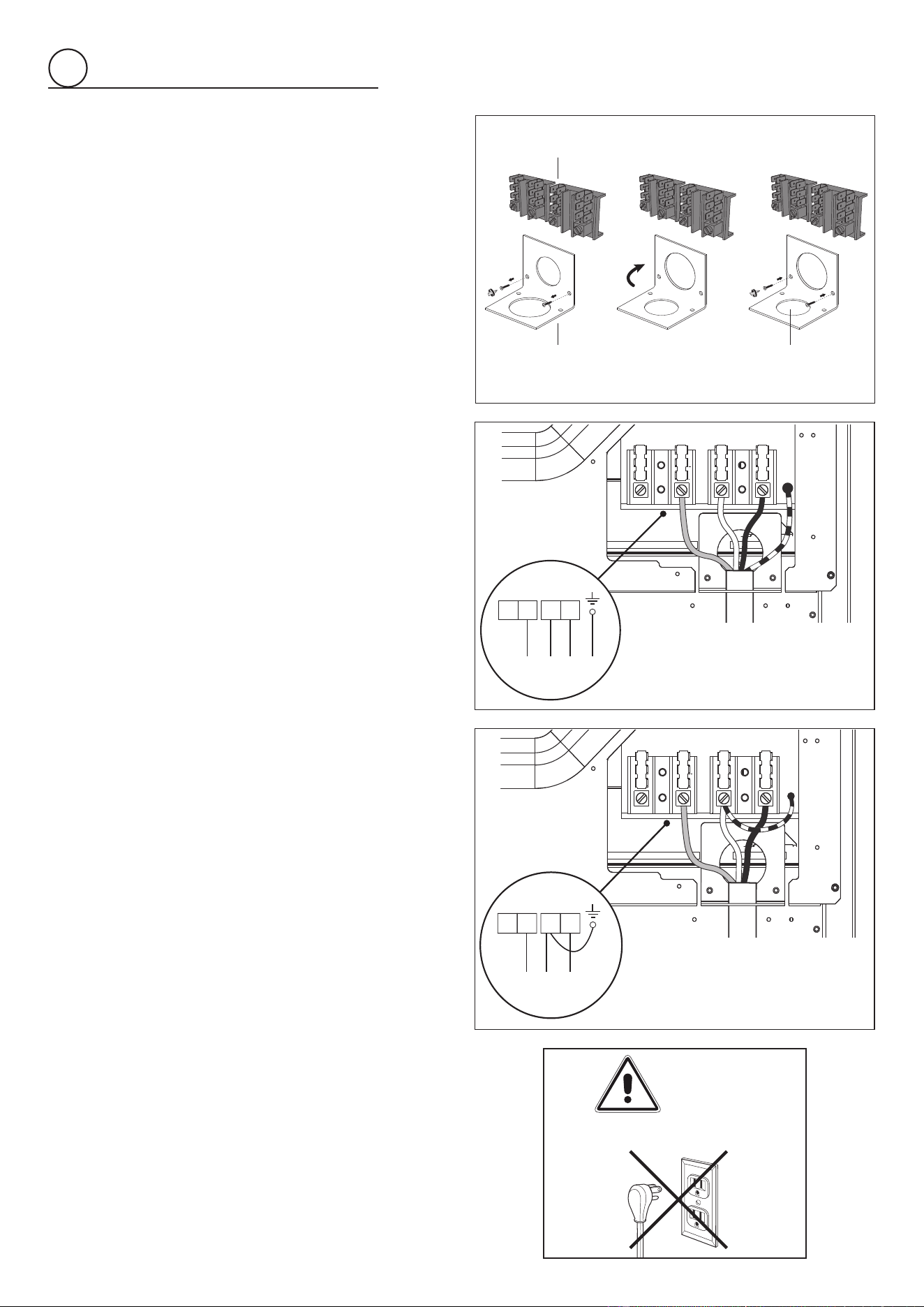
• The strain relief bracket orientation must be so that the 7/8”
(22mm) smaller opening is facing down (fig. 3.1). If not, the
strain relief bracket orientation must be switched in order to
accommodate for a permanent wiring connection:
1. If fitted, remove the factory supplied power cord with
plug.
1. Remove the 2 screws on the bracket.
2. Re-secure bracket with the 2 screws so that the 7/8”
(22mm) smaller opening is facing down.
• The conduit must be installed to the terminal block using
an approved conduit connector. The free end of the conduit
must be connected to a junction box provided in the electrical
supply zone.
• Mount a strain relief (not provided) into the 7/8” (22mm)
diameter hole located below the terminal block.
Wiring for the unit is to be brought into the terminal block
through the conduit and through the strain relief. Make
suitable connections to the terminal block provided.
• Installer — Show the owner the location of the circuit breaker.
Mark it for easy reference.
4-Wire Installation (fig. 3.2)
1. Loosen the L1, L2 and neutral screws.
2. Mount the conduit fitting to the 7/8” (22mm) hole in the strain
relief bracket.
3. Secure the neutral power lead to the center terminal and
tighten the screw.
4. Secure the L1 and the L2 power leads to the terminals
immediately to the left (L1) and right (L2) of the neutral
terminal. Tighten the screws.
5. Secure the Ground lead to the green screw located to the
right of the terminal block using the supplied cupped washer.
The end of the grounding conductor must be retained by the
cupped washer.
6. Check all connections are securely tightened.
7. Reinstall the Terminal Block cover.
3-Wire Connection (using supplied Ground lead)
(fig. 3.3)
1. Loosen the L1, L2 and neutral screws.
2. Mount the conduit fitting to the 7/8” (22mm) hole in the strain
relief bracket.
3. Secure the supplied Ground lead to the grounding screw to
the right of the terminal block.
4. Secure the Neutral power lead together with the free end of
the Ground lead to the center terminal. Tighten the screw.
5. Secure the L1 and the L2 power leads to the terminals
immediately to the left (L1) and right (L2) of the neutral
terminal. Tighten the screws.
6. Check all connections are securely tightened.
7. Reinstall the Terminal Block cover.
1 2 3
Terminal Block
Smaller opening
Strain relief bracket
Fig. 3.1
L1
N
L2
PE
Fig. 3.2
L1 N L2
PE
Fig. 3.3
WARNING
DO NOT FIT A 3-PRONG PLUG
2323
3
Before any operation of maintenance
disconnect the appliance from the
electrical main supply.
RANGES SUPPLIED WITH POWER CORD (WITH PLUG)
ALREADY FITTED
If codes permit and a separate ground wire is used, it is recommended that a
qualied electrician installer determine that the ground path and wire gauge are in
accordance with local codes.
Be sure that the electrical connection and wire size are adequate and in conformance
with:
• ANSI/NFPA 70 latest edition and local codes and ordinances;
• CSA Standard C22.1, Canadian Electrical Code, Part 1 - latest edition, and all local
codes and ordinances.
ONLY FOR CANADA:
A copy of the above code standards can be obtained from:
CANADIAN STANDARDS ASSOCIATION
178 Rexdale Boulevard
TORONTO, ON M9W 1R3
CANADA
• Do not ground to a gas pipe.
• Check with a qualied electrical installer if you are not sure the range is properly
grounded.
• Do not have a fuse in the neutral or ground circuit.
• When a 4-wire, two phase 240-208/120-volt, 60Hz, AC-only electrical supply is
available, a 30 amp maximum circuit protection is required, fused on both sides of
the line.
• A time-delay fuse or circuit breaker is recommended.
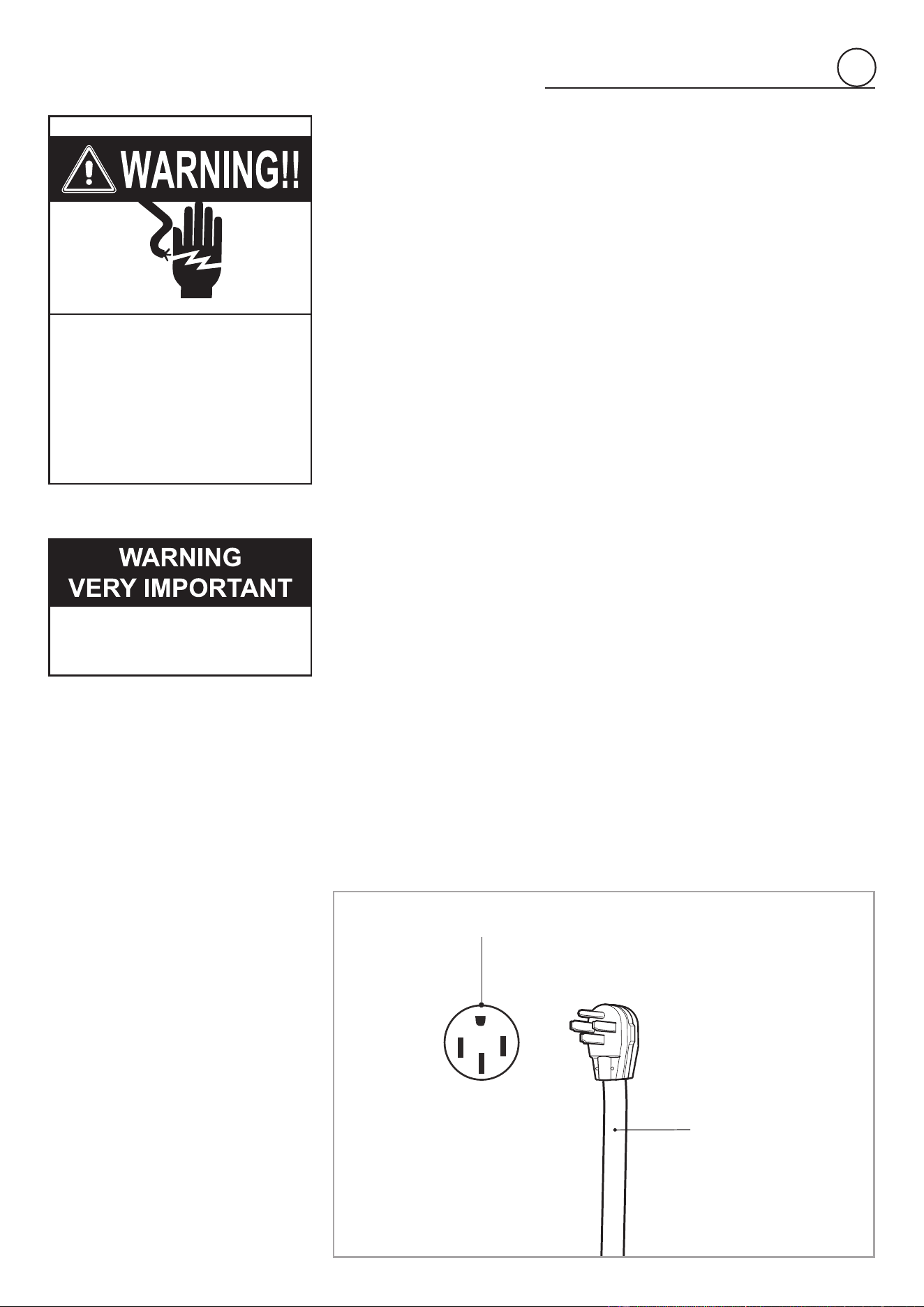
• This range is equipped with a Certied Power Cord intended to be plugged into
a standard 14-50R wall receptacle. Be sure the wall receptacle is within reach of
range’s nal location.
• Do not use an extension cord.
In the case of substitution of the power cord always replace it with a suitable UL or CSA
approved one (with the same technical features of the replaced cord).
Tighten the power cord by using only the power cord strain relief bracket supplied with
the appliance.
Allow enough slack to easily attach the cord terminals to the terminal block.
These operations must be carried out only by an authorized technician.
Electrical Shock Hazard
Plug into a grounded outlet.
Do not remove ground prong.
Do not use an adapter.
Failure to follow these
instructions can result in death,
re, or electrical shock.
Power supply cord with
NEMA 14-50P plug
Standard NEMA 14-50R wall receptable
Fig. 3.4
IMPORTANT!
The fourth (ground) prong
should not, under ANY
circumstances, be cut or
removed.
2424
3
Tl1
N/7
1
2
1a
2a
L/8
1
6
P1
P6
4
P4
3
8
P3
P8
2
7
P2
P7
5
P5
F1
C
CIR
S
G
V
LF
M
CF
TM
S1
PR
V
CIR
LF
LF
S2
TS
E
LF
ignition switces
Ignition coil
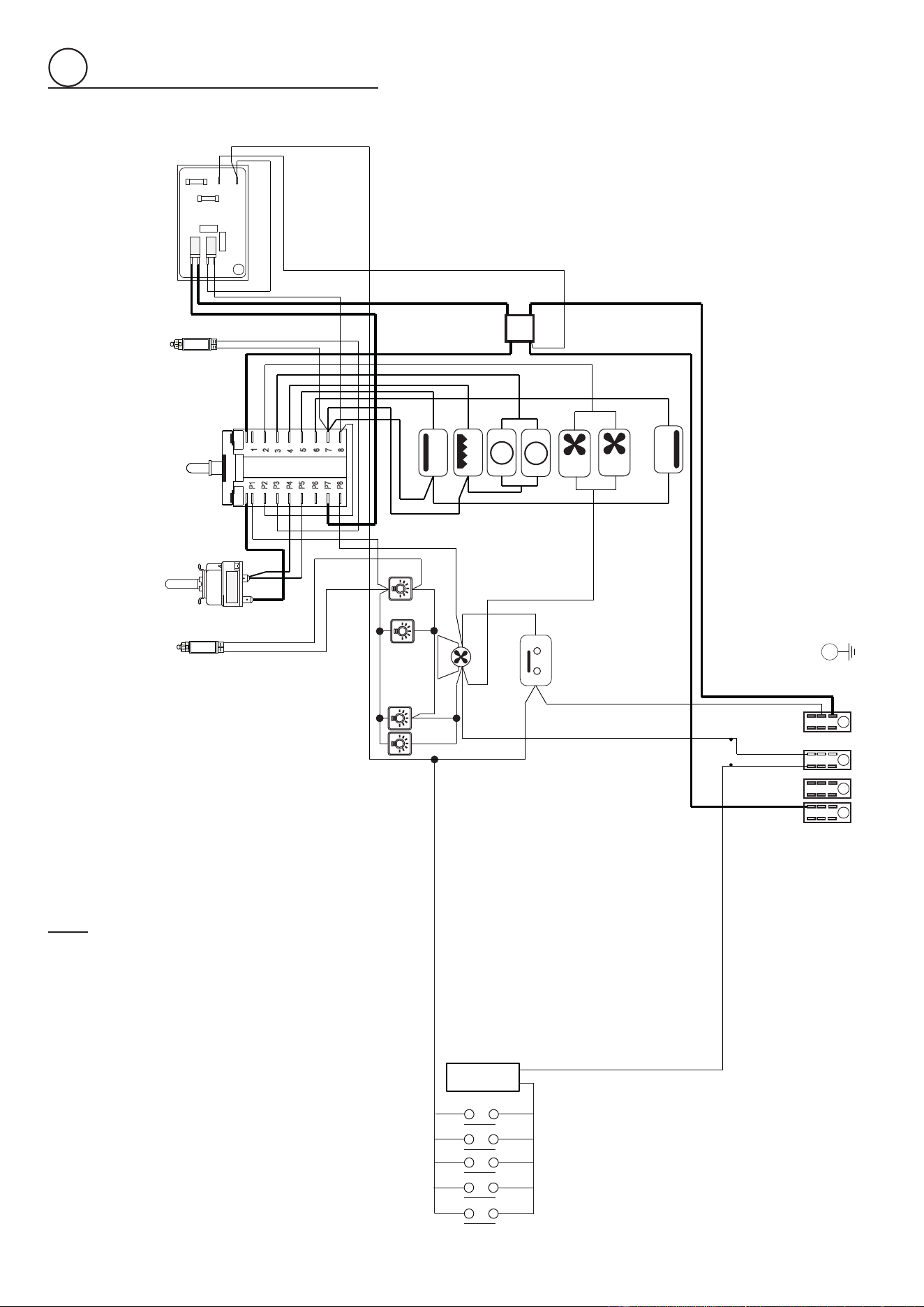
ELECTRIC DIAGRAM KEY
Tl1 Cooling fan thermolimiter
CF Cooling fan
TS
Security thermal overload
M Terminal block
E Earth plant
OVEN
F1 Oven switch
TM Oven thermostat
PR
Programmer
TL Thermal overload
LF Oven lamp
S1
Thermostat pilot lamp
C Top element
G Grill element
CIR
Circular element
V Fan
S Bottom element

2525

2626

2727

Cod 1106721 - ß0
The manufacturer cannot be held responsible for possible inaccuracies due to
printing or transcription errors in the present booklet.
The manufacturer reserves the right to make all modications to its products deemed
necessary for manufacture or commercial reasons at any moment and without prior
notice, without jeopardising the essential functional and safety characteristics of the
appliances.