McIntosh Laboratory, Inc. 2 Chambers Street Binghamton, New York 13903-2699 Phone: 607-723-3512 www.mcintoshlabs.com
MIP200MIP200
POWER CONTROLLER
OWNER’S MANUAL

2
Thank You from All of Us at McIntosh
You have invested in a precision instrument that will
provide you with many years of enjoyment. Please
take a few moments to familiarize yourself with
the features and instructions to get the maximum
performance from your equipment.
If you need further technical assistance, please
contact your dealer who may be more familiar with
your particular setup including other brands. You can
also contact McIntosh with additional questions or in
the unlikely event of needing service.
McIntosh Laboratory, Inc.
2 Chambers Street
Binghamton, New York 13903
Technical Assistance
(607) 723-3512
Fax (607) 724-0549
Customer Service (607) 723-3515
Fax (607) 723-1917
Email support@mcintoshlabs.com
Website
www.mcintoshlabs.com
Please Take A Moment
For future reference, you can write down your
serial number and purchase information here. We
can identify your purchase from this information
if the occasion should arise:
Serial Number:
__________________________
Purchase Date: ___________________________
Dealer Name: ___________________________
Table of Contents
Introduction.. .. .. .. .. .. .. .. .. .. .. .. .. .. .. 2
General Information
.. .. .. .. .. .. .. .. .. .. .. 3
Performance Features
. .. .. .. .. .. .. .. .. .. .. 3
Dimensions
.. .. .. .. .. .. .. .. .. .. .. .. .. .. 4-5
Rack Mounting
. .. .. .. .. .. .. .. .. .. .. .. .. .. 5
MIP200 Front Panel
.. .. .. .. .. .. .. .. .. .. .. 6
Front Panel Displays and Switches
. .. .. .. .. .. 6
Connector Information
.. .. .. .. .. .. .. .. .. .. 7
MIP200 Rear Panel
. .. .. .. .. .. .. .. .. .. .. .. 8
Rear Panel Connections and Switches
.. .. .. .. 8
MIP200 Connection Diagram
. .. .. .. .. .. .. .. 9
Setup Menu
.. .. .. .. .. .. .. .. .. .. .. .. .. .. ..10
Outlet Submenu
.. .. .. .. .. .. .. .. .. .. .. .. ..11
Trim Menu
.. .. .. .. .. .. .. .. .. .. .. .. .. .. ..12
How to Operate
.. .. .. .. .. .. .. .. .. .. .. .. ..13
MIP200 (100V-120V ) Specifications
.. .. .. .. ..14
MIP200 (220V-240V ) Specifications
. .. .. .. ..14
Packing Instructions
.. .. .. .. .. .. .. .. .. .. ..15
Part List
.. .. .. .. .. .. .. .. .. .. .. .. .. .. .. ..15
Introduction
Protect your home audio investment with the MIP200
Power Controller. The MIP200 delivers AC power
line surge protection, such as from a lightning strike,
overvoltage protection (when there is too much power)
and under voltage protection (commonly referred to as
a brownout). All of this protection comes with a host
of programmable control options.
Safety First
Please read the safety instructions included in a
separate document called “Important Additional
Operation Information Guide.”

3
MIP200
General Information
Performance Features
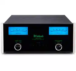
• Illuminated Glass Front Panel
The famous McIntosh illuminated front panel
is made from 1/8 inch thick glass and uses Light
Emitting Diodes (LEDs) for even illumination and
long life.
• AC Line Surge Protection
The MIP200 uses a TPMOV (Thermally Protected
Metal Oxide Varistor) that eliminates common
failure modes associated with standard MOVs.
• AC Line Filtering
The MIP200 oers EMI ltering that provides
electromagnetic noise suppression to all compo-
nents connected to the outlets.
• AC Line Meter / Monitor
The MIP200 uses a power line monitoring IC
(Integrated Circuit) to constantly monitor and
display AC line voltage, current, and power. Over
and under voltage limits can be set to automatically
turn the outlets o should those conditions occur.
• Power Control
The MIP200 power control inputs provide
remote control of the switched outlets and can be
congured individually. Power control outputs pass
control signals on to other components.
• RS232 Control
The MIP200 RS232 port allows for connection of
third party control systems. Control of the switched
outlets and various operating functions can be made
remotely using RS232 protocol.
1. For additional connection information, refer to the
owner’s manual(s) for component(s) connected to the
MIP200.
2. There are two dierent versions of the MIP200.
Each version has dierent AC outlet connectors and
operate on either 100-120Volts or 220-240Volts. This
MIP200 owner’s manual contains information about
both versions of the MIP200 to meet the dierent
AC power and safety requirements for use in your
country.
3. The Main AC Power going to the MIP200 and any
other component(s) should not be applied until all
the system components are connected together.
Failure to do so could result in malfunctioning of
some or all of the system’s normal operations.
4. The MIP200 is designed for connection with audio/
video components. This would include components
such as preampliers, A/V control centers, source
components, integrated ampliers and power
ampliers with low to modest power output.
5. The total amount of current drawn by all the
components connected to the MIP200 should not
exceed the current amperage rating indicated on the
rear panel of your MIP200. Typically, components
consuming low amounts of energy are rated in
wattage instead of current.
6. The MIP200 has been tested and certied for indoor
use only.
7. To protect the anodized nish on your MIP200, it
is important to limit exposure to certain types of
lighting and only use appropriate gentle cleaners.
Direct sunlight, other forms of UV light, high
intensity lighting and aggressive cleaners with harsh
chemicals can result in discoloration of the anodized
nish.
8. For additional information on the MIP200 and
other McIntosh products please visit the McIntosh
website at www.mcintoshlabs.com.
4
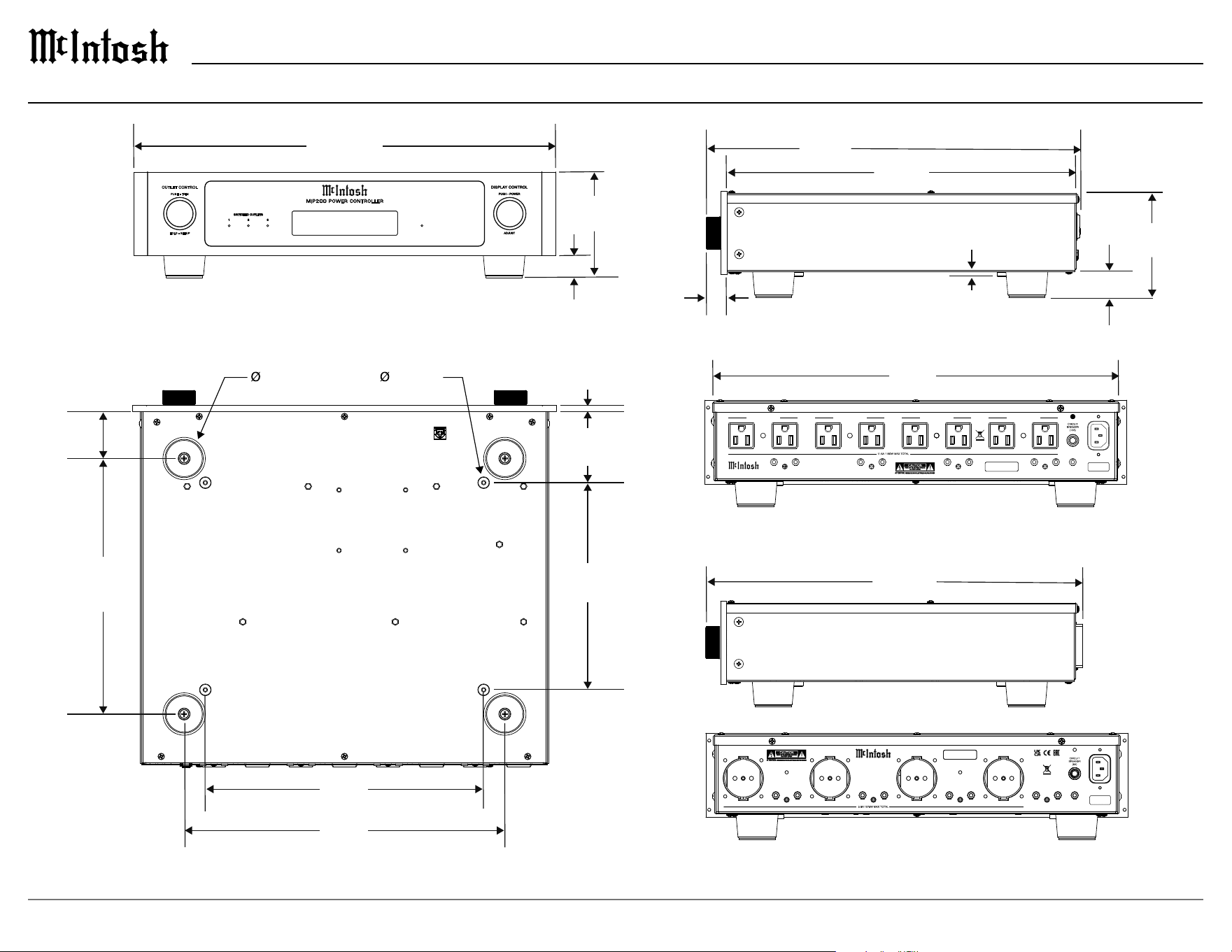
Dimensions
³⁄16”
.5 cm
4 ⁵⁄16”
10.9 cm
⁷⁄8”
2.2 cm
SERIAL
NUMBER
MIP2 00 PO WER C ONTR OLLER
Mc , .INTOSH LABORATORY INC
BINGHAMTON NY,
HANDCRAF TED IN USA
WITH US AND IM PORTED PARTS
UNSWITCHED OUTLETSWITCHED OUTLET 1
IN
OUT
POWER CONTROL 3
IN
OUT
POWER CONTROL 2
IN
OUT
POWER CONTROL 1
IN
OUT
MAIN POWER CONTROL
SWITCHED OUTLET 2SWITCHED OUTLET 3
RS232
CONTROL
SERIAL
NUMBER
MIP 200 POWER CONT ROL LER
Mc , .INTOSH LABORATORY INC
BINGHAMTON NY,
HANDCRAF TED IN USA
WITH US AND IM PORTED PARTS
UNSWITCHED OUTLETSWITCHED OUTLET 1
IN
OUT
POWER CONTROL 3
IN
OUT
POWER CONTROL 2
IN
OUT
POWER CONTROL 1
IN
OUT
MAIN POWER CONTROL
SWITCHED OUTLET 2SWITCHED OUTLET 3
RS232
CONTROL
16 ⁷⁄8”
42.9 cm
1¹⁄16”
2.7 cm
15 ⁹⁄16”
39.5 cm
14 ¹⁹⁄32”
37.1 cm
15 ²³⁄32”
39.9 cm
17 ¹⁄2”
44.5 cm
4 ⁷⁄16”
11.3 cm
¹⁵⁄16”
2.4 cm
1 ³⁄4”
4.4 cm
¹⁄2”
1.3 cm
2 ¹⁵⁄16”
7.5 cm
8 ¹⁵⁄32”
8.5 cm
11 ¹⁄2”
29.2 cm
13 ¹⁄4”
33.7 cm
10 ⁹⁄16”
26.8 cm
1 ¹⁵⁄16”
4.9 cm
¹⁄4”
.6 cm
VOLTS AC Amps
120.6 LINE 5.83
M I P 2 0 0 P OW E R C O N T RO LL E R
OUT LET CONTR OL
1 2 3
SWIT CHED OUTLETS
HOLD - S ETUP
PUSH - T RIM
100V - 120V
220V - 240V
5
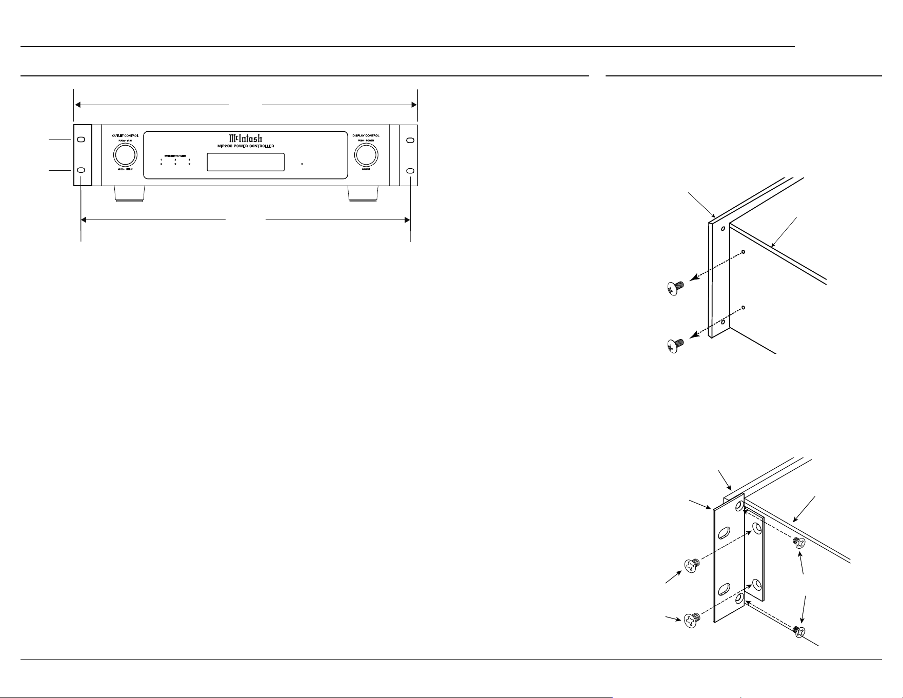
MIP200
Front Panel
Side Panel
Rack
Mounting
Bracket
Larger
Supplied
Screws
Smaller Supplied
Screws
Front Panel
Side Panel
BRACKET MOUNT No Wash 2
Rack Mounting
To rack mount the MIP200, the two included rack
mounting brackets should be installed.
Follow these instructions for each side:
1. Remove the two screws from the MIP200’s
side panel. Save these for future use if the
mounting brackets are removed.
2. Secure the rack mounting bracket to the
MIP200 side panel using 2 of the 8-32 thread
(larger) athead screws. Do not re-use the
previously removed screws. Use 2 of the
supplied 6-32 thread (smaller) athead screws
to secure the bracket to the front panel.
VOLTS AC Amps
120.6 LINE 5.83
M I P 2 0 0 P OW ER C O N T R O LL ER
1 2 3
SWIT CHED OUTLETS
19”
48.3 cm
1³⁄4”
4.4 cm
18 ⁵⁄16”
46.5 cm
OUT LET CONTR OL
HOLD - S ETUP
PUSH - T RIM
Dimensions (continued)
6
VOLTS AC Amps
120.6 LINE 5.83
M I P 2 0 0 P O W E R C O N T R O L L E R
1 2 3
SWITCHED OUTLETS
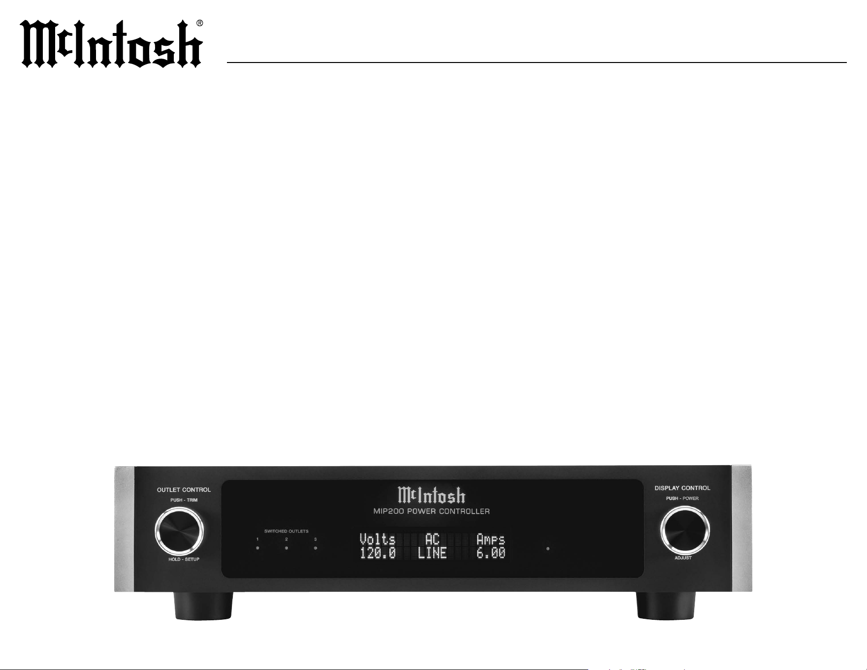
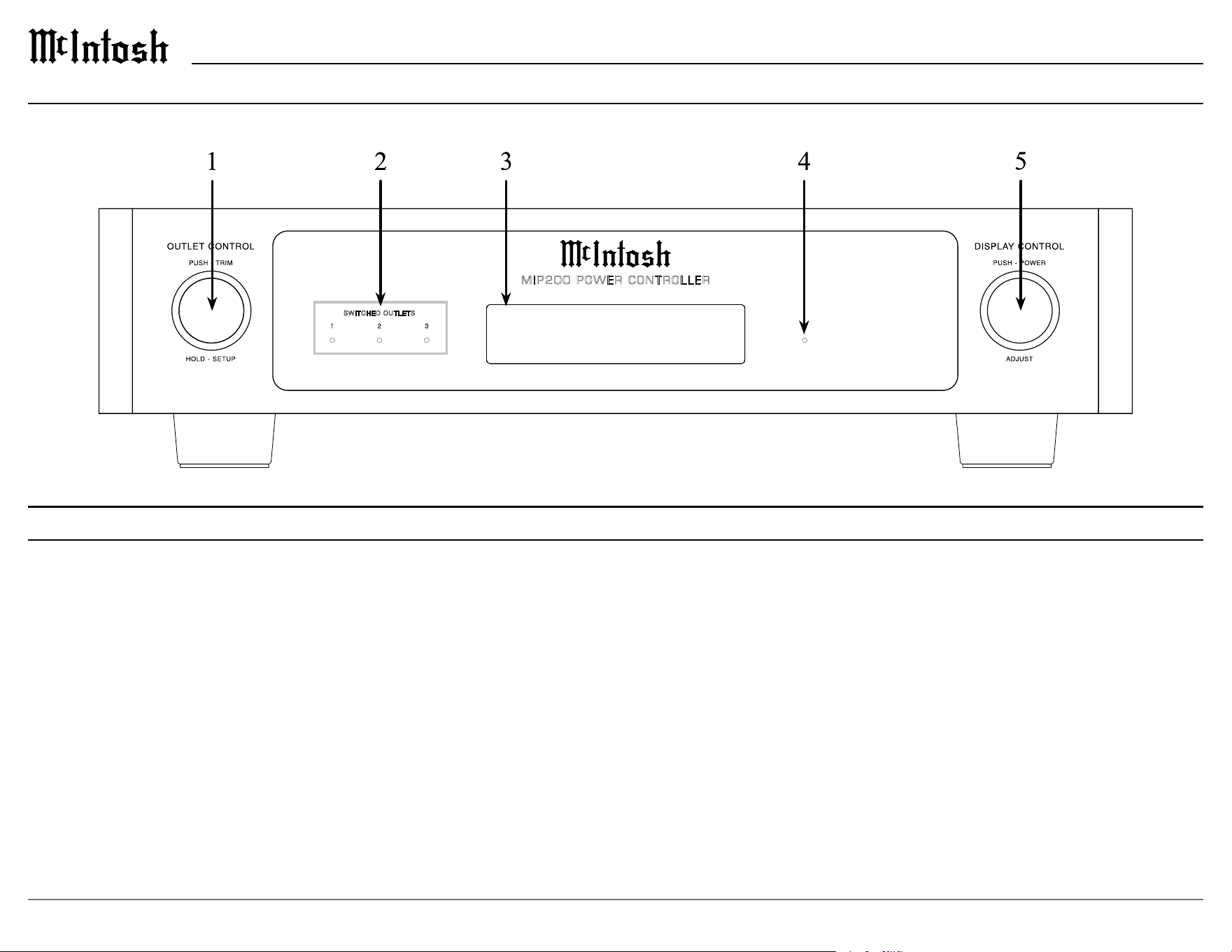
1. OUTLET CONTROL knob
Rotate to select which of the three
SWITCHED OUTLETS are to be controlled.
PUSH to access the trim menu. HOLD to
access the setup menu.
2. SWITCHED OUTLET Indicators
Indicates the state of each of the three
SWITCHED OUTLETS. When illuminated,
the outlet is on.
Front Panel Displays and Switches
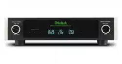
3. Information Display
Indicates AC line monitor readings as well
as options for the SWITCHED OUTLETS,
trim menu and setup menu.
4. AC Power Indicator
Illuminates whenever the MIP200 is
connected to a live AC circuit. Flashes when
AC surge protection has triggered, or an
over/under voltage condition has occurred.
Also used to indicate a reset of the internal
microprocessor.
MIP200 Front Panel
5. DISPLAY CONTROL knob
PUSH to turn the MIP200 on or o. Rotate
to select various display options for the AC
line monitor. ADJUST (rotate) to change
states when controlling the SWITCHED
OUTLETS and to select trim and setup
menu options.
7
MIP200
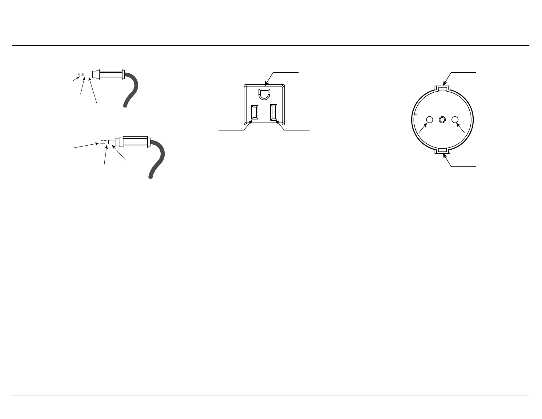
Connector Information
Meter
Illumination
Control
Power
Control
Ground
Power Control Connectors
RS232 Connectors
Safety Ground
Safety Ground
AC Line AC Neutral
Safety Ground
AC Line AC Neutral
RXD
(Data recieved by MIP200)
TXD
(Data transmitted by MIP200)
Ground
100V - 120V Outlets
220V - 240V Outlets
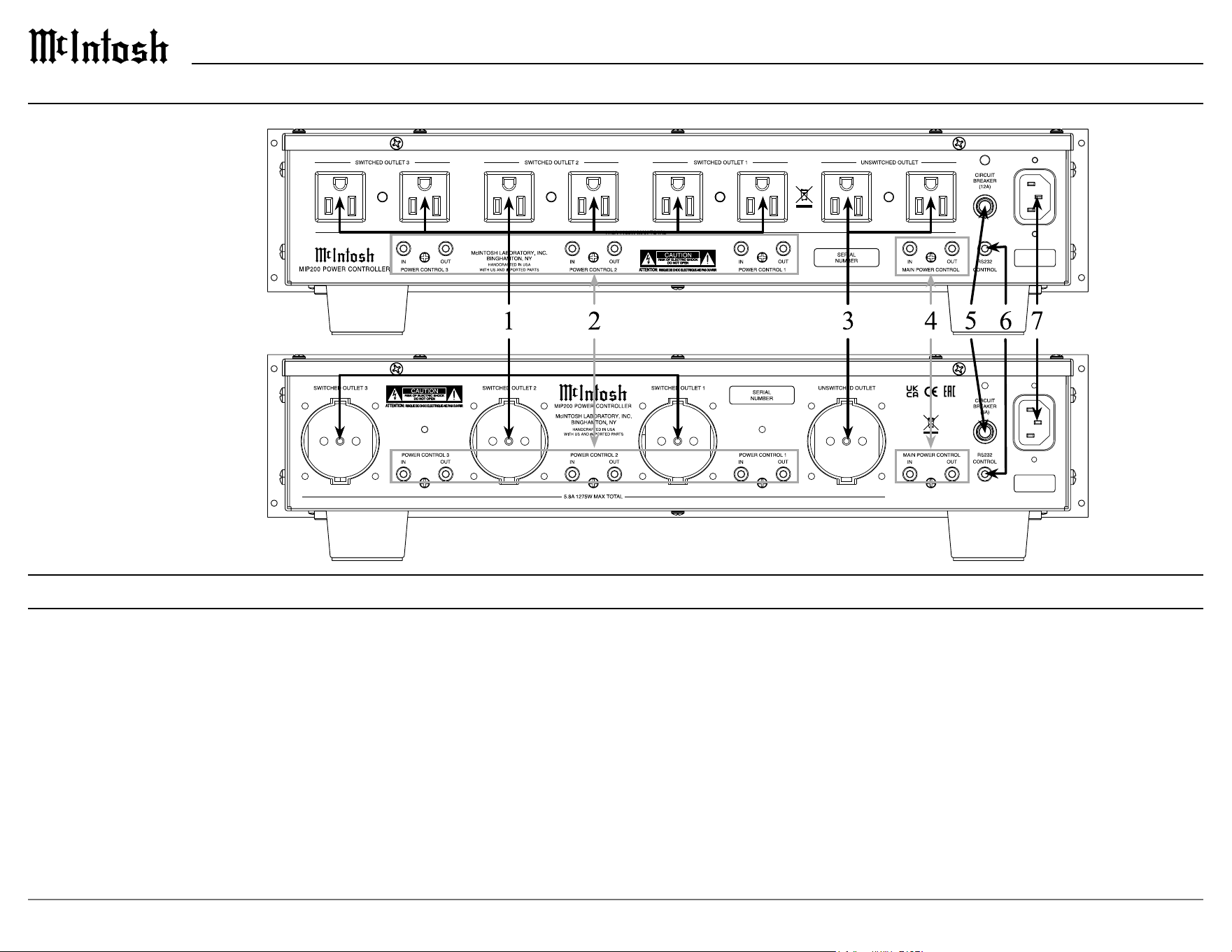
8
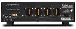
Rear Panel Connections and Switches
1. SWITCHED OUTLETS
These outlets can be turned on and o using the
front panel OUTLET CONTROL knob or rear panel
POWER CONTROL IN connectors. If over/under
voltage protection has been enabled, these outlets
will switch o should that condition occur.
2. POWER CONTROL 1, 2, 3
IN connectors are used to turn on the front
panel lighting and display and then turn on the
SWITCHED OUTLET that has been congured to
respond to its associated POWER CONTROL IN.
The OUT connectors pass the POWER CONTROL
IN signal onto other system components.
3. UNSWITCHED OUTLET
This outlet is always on whenever the MIP200 is
connected to a live AC circuit. If over/under voltage
protection has been enabled, the outlet will switch
o should that condition occur.
4. MAIN POWER CONTROL
The IN connector is used to turn on the front
panel lighting and display and then turn on any
SWITCHED OUTLET that has been congured
to respond to MAIN POWER CONTROL IN.
The OUT connector generates a 12V DC signal
whenever the MIP200 is powered on.
5. CIRCUIT BREAKER
Should the MIP200 input current exceed its
rating, the CIRCUIT BREAKER will activate and
disconnect AC power to the MIP200. Should this
happen the tip of the breaker will pop out. Reset the
breaker by pushing in on the tip.
6. RS232 CONTROL
This connector is used for external control devices
that use RS232 protocol. Control of the SWITCHED
OUTLETS as well as trim menu functions can be
controlled using pre-dened RS232 commands.
7. AC Input
Connect to a live AC outlet according to the AC
input rating label.
MIP200 Rear Panel
100V - 120V
220V - 240V
9
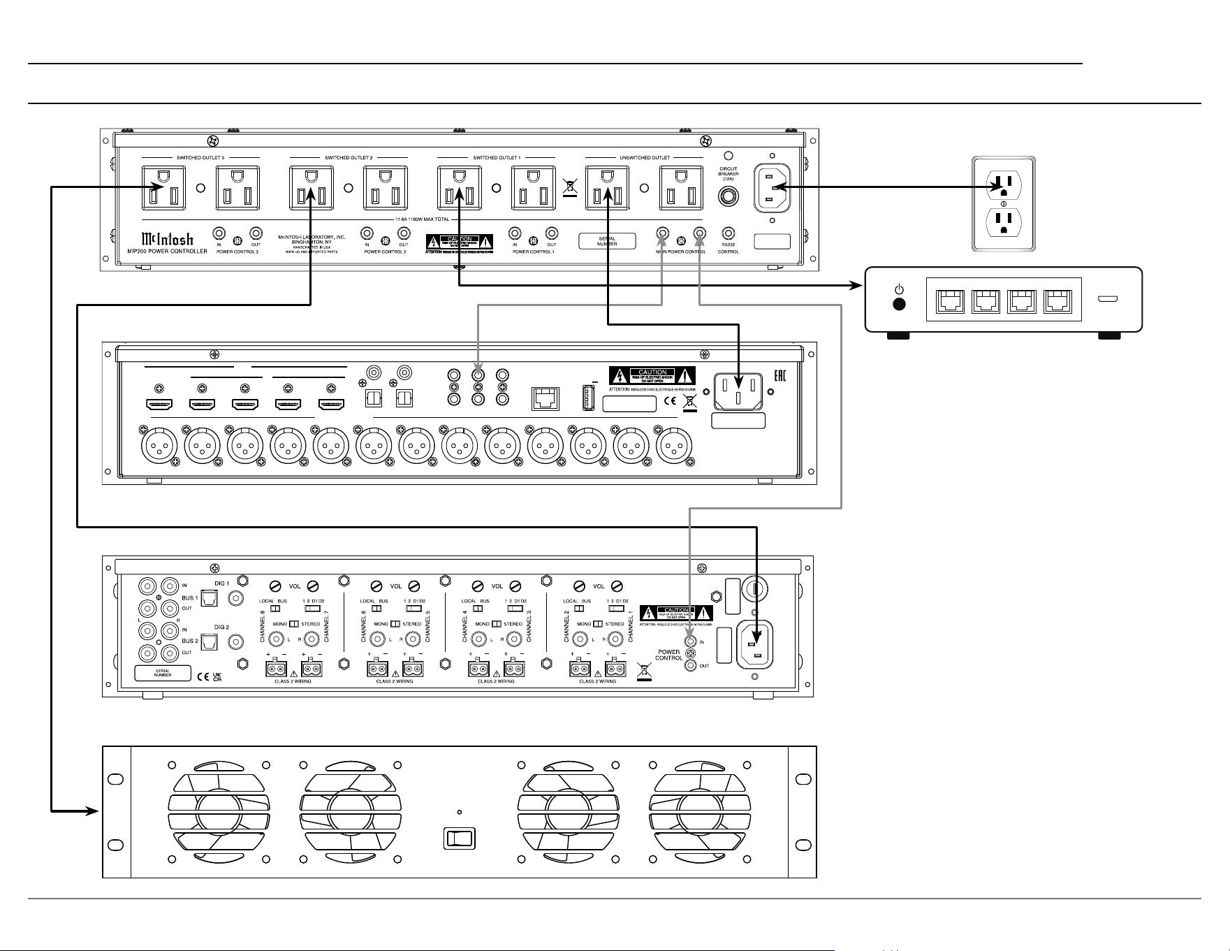
MIP200
MIP200 Connection Diagram
HDMI
IN
1 2
3
4
RS232
TRIG 1 IR IN
TRIG 2
2
OPT
COAX
1
1
2
OUT/eARC
DATA OUTSETUP MIC
SERIAL
NUMBER
BALANCED OUTPUTS
RF LF C LS RB LB RH1RS LH1 RH2 LH2 SW1 SW2
NET
DIGITAL INPUTS
SERVICE
USB
5V/1A
NET NET NET NET
In this connection example, a home theater
processor, power amplier, network router
and equipment rack fan are shown connected
to the MIP200. The processor is connected to
the UNSWITCHED OUTLET so it always has
power and would be in standby mode.
The router and amplier are connected to
SWITCHED OUTLETS that have been cong-
ured to be ON. By being congured to ON they
act as additional unswitched outlets so they
always have power as well. A power control
signal from TRIG 1 of the processor will then
turn on the MIP200 front panel and then turn
on the amplier.
The equipment rack fan is connected to
SWITCHED OUTLET 3 which is congured to
only come on with MAIN POWER CONTROL.
By being congured for MAIN POWER
CONTROL the fan will only come on when the
system is turned on by the processor.
10
Nominal Voltage
The nominal voltage sets the expected AC Line
voltage that the MIP200 will be plugged into. Based
on your version of the MIP200, this will be either
100, 110, 120 Volts, or 220, 230, 240 Volts. Your
MIP200 should already be congured to the correct
Nominal Voltage based on your country. To change
the nominal voltage, rotate the DISPLAY CONTROL
knob until the correct voltage is selected.
RS232
The MIP200 may be remotely controlled from other
equipment connected to the Rear Panel RS232 Jack.
The speed at which the MIP200 communicates (8
bit, no parity and 1 stop bit) with other equipment
is adjustable from 9,600 bits per second to 115,200
bits per second. To change from the default speed
of 115,200 bits per second, rotate the DISPLAY
CONTROL knob until the desired bit rate is selected.
Factory Reset
To reset all adjustable settings to the factory default
values, perform the following steps:
1. Hold the OUTLET CONTROL knob until the
following appears on the Information Display, then
release the INPUT knob.
SETUP: < Factory
In Progress...
2. Once the factory reset is completed, the MIP200
will turn o. Push the DISPLAY CONTROL knob
to turn the MIP200 on.
Your McIntosh MIP200 has been factory congured
for default operating settings that allow immediate
operation. If you wish to make changes to the default
congurations, a Setup Menu is provided to custom-
ize the operating settings using the Information
Display.
Navigating the Setup Menu
1. To open the Setup Menu, press and hold in the
OUTLET CONTROL knob until the Information
Display indicates:
SETUP: Product >
MIP200-AMR####
2. Rotate the OUTLET CONTROL knob to select the
desired setting.
3. Rotate the DISPLAY CONTROL knob to change
the selected setting’s options.
4. To exit from the Setup Menu or a submenu, press
the OUTLET CONTROL knob.
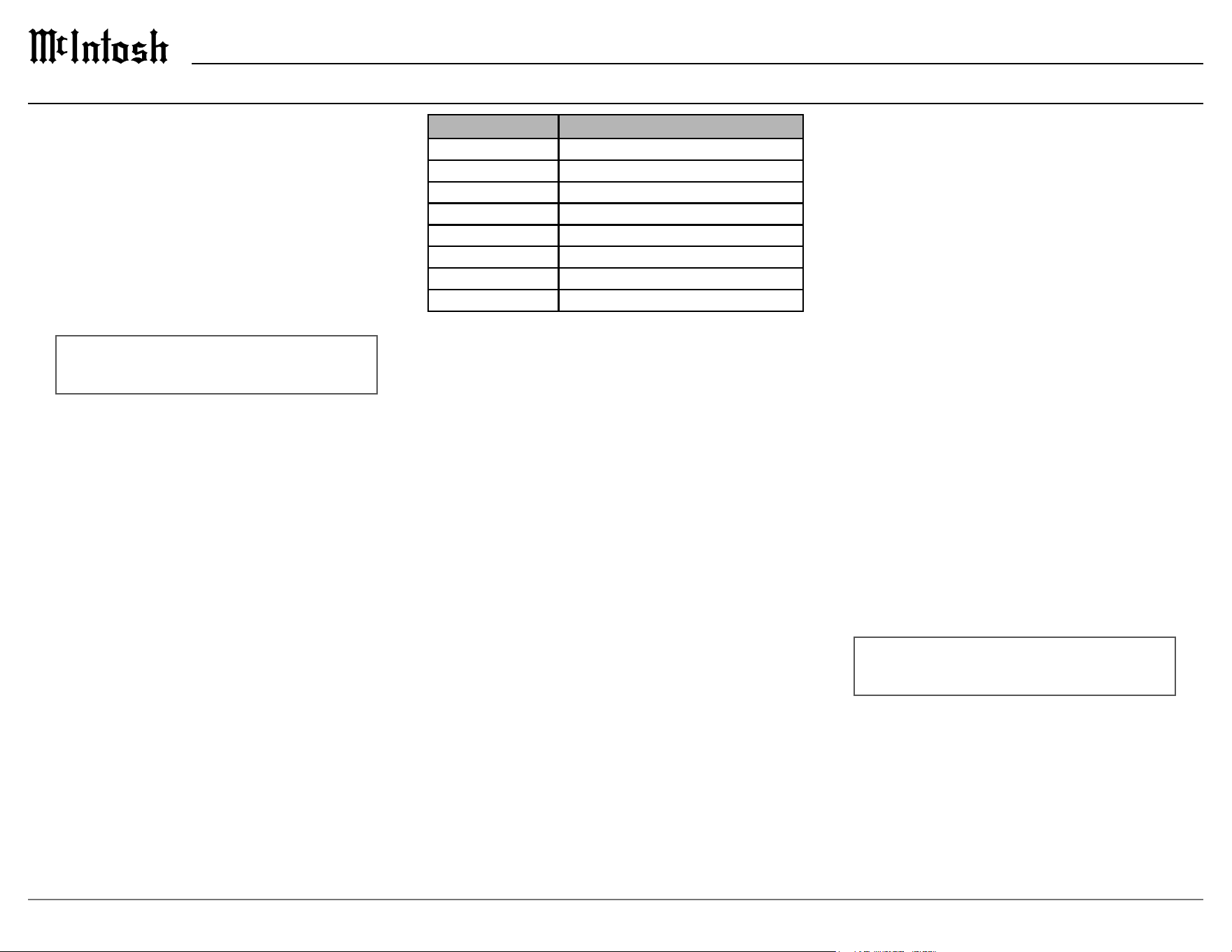
Setup Menu
Settings Options
Product Information MIP200-AMRXXXX
Version __.__.__
Outlet 1 Remote, Delay, Name
Outlet 2 Remote, Delay, Name
Outlet 3 Remote, Delay, Name
Nominal Voltage 100, 110, 120 (220, 230, 240)
RS232 Baud Rate 9600, 19200, 38400, 57600, 115200 Baud
Factory Reset Reset to defaults
Product Information
The product information contains the product name
and serial number.
Version
The version number indicates the version of the
MIP200 rmware. The rmware controls the internal
circuitry of the MIP200.
Outlet 1
Refer to the Outlet Submenu section on the following
page for a description of how to congure Outlet 1.
Outlet 2
Refer to the Outlet Submenu section on the following
page for a description of how to congure Outlet 2.
Outlet 3
Refer to the Outlet Submenu section on the following
page for a description of how to congure Outlet 3.
11
MIP200
Outlets 1, 2, and 3 each have their own submenu
to congure them individually. To enter an outlet’s
submenu, rotate the OUTLET CONTROL knob in
the Setup Menu until the desired outlet is selected,
then hold the OUTLET CONTROL knob. Each
submenu has three conguration options: Remote
Power Control, Delay, and Name.
Settings Options
Remote Power Control Main Power Control, Power Control #
Delay O, 1 second, 2 seconds, 3 seconds
Name
Remote Power Control
The Remote Power Control setting determines which
type of POWER CONTROL IN connectors control
the switched outlet. By default, it is set to the Main
Power Control connector. To change the Remote
Power Control to Power Control 1, 2, or 3 (outlet
specic), perform the following steps:
1. Rotate the DISPLAY CONTROL knob until the
following appears on the Information Display.
OUTLET #: Remote >
< Power Control 1
2. To exit the Outlet Submenu and return to the Setup
Menu, press the OUTLET CONTROL knob again
or use the OUTLET CONTROL knob to navigate
to the next setting.
Outlet Submenu
Delay
The Delay setting controls how long the outlet takes
to turn on after a Remote Power Control signal. By
default, the Delay is set to O, but can be congured
to 1, 2 or 3 seconds. To change the Delay, perform
the following steps:
1. Rotate the OUTLET CONTROL knob until the
following appears on the Information Display:
OUTLET #: < Delay >
Off >
2. Rotate the DISPLAY CONTROL knob until the
desired setting is selected.
OUTLET #: < Delay >
< 2 seconds >
3. To exit the Outlet Submenu and return to the Setup
Menu, press the OUTLET CONTROL knob again
or use the OUTLET CONTROL knob to navigate
to the next setting.
Name
1. To change the name of Outlet 1, rotate the
OUTLET CONTROL knob until the Information
Display indicates:
OUTLET #: < Name
(Hold OUTLET)
2. Press and Hold the OUTLET CONTROL knob to
enter the Outlet 1 naming menu:
RENAME: OUTLET 1
>OUTLET 1 <
3. The character you are currently changing will be
blinking. Rotate the OUTLET CONTROL knob
to select which character to change, then rotate the
DISPLAY CONTROL knob to change the selected
character.
4. To save the new name, press and hold the
OUTLET CONTROL knob. The new name will
replace the old name.
5. To exit the naming menu, press the OUTLET
CONTROL knob.
6. To exit the Outlet Submenu and return to the Setup
Menu, press the OUTLET CONTROL knob again.
12
Over Voltage
The Over Voltage protection feature will turn o
all outlets if the AC line exceeds the set limit. This
threshold can be congured to protect against
voltages either 5% or 10% above the Nominal
Voltage value (see Setup Menu). By default, the Over
Voltage is set to O, which disables the protection.
Under Voltage
The Under Voltage protection feature will turn o
all outlets if the AC line falls below the set limit.
This threshold can be congured to protect against
voltages either 5% or 10% below the Nominal
Voltage value (see Setup Menu). By default, the
Under Voltage is set to O, which disables the
protection.
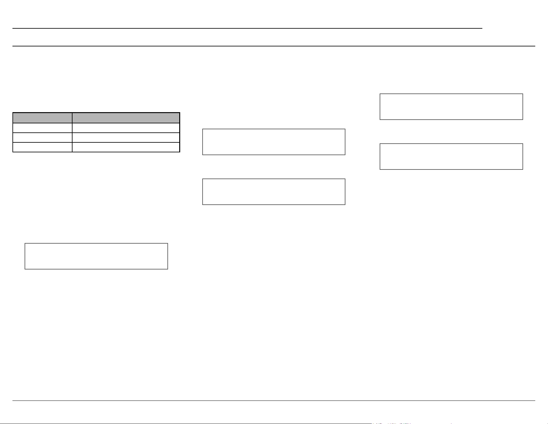
How to Select and Adjust Trim Functions
1. Press the Front Panel OUTLET CONTROL knob
to open the Trim Menu.
2. Rotate it to select the desired Trim Function.
3. Rotate the DISPLAY CONTROL knob to change
the setting.
Approximately 5 seconds after making any changes,
the Information Display will return to indicate the
AC line monitor / meter.
Trim Functions Menu Options
Settings Options
Brightness 4 Levels from Dim Bright
Display Always On, Auto Sleep
Over Voltage O, 5%, 10%
Under Volt age O, 5%, 10%
Brightness
The brightness level of the Information Display can
be adjusted. It has 4 levels that vary from dim to
bright.
Display
When the Display control is set to Auto Sleep, the
Information Display will automatically turn o. This
occurs approximately 30 minutes after there has been
an absence of user activity (includes power controls).
By default, it is set to Always On.
Trim Menu

13
MIP200
How to Operate
Display On and O
To turn on the Information Display, push the
DISPLAY CONTROL knob. The MIP200 will go
through a brief initialization, and then indicate the
last used AC line display.
Volts AC Amps
118.0 LINE 0.00
To turn o the Information Display, push the
DISPLAY CONTROL knob. Turning the Information
Display does not control any Switched or Unswitched
Outlets
AC Line Monitor Readings
The MIP200 provides four dierent AC line
readings: Composite, Power, Voltage, and Current.
To select the desired reading, rotate the DISPLAY
CONTROL knob.
AC LINE POWER
0.0 Watts
Switched Outlet Control
The MIP200 has three Switched Outlets that are
independently congurable. Rotate the OUTLET
CONTROL knob to select the desired Outlet. If
an outlet has been renamed in the Setup Menu, its
custom name is displayed here. Each Outlet has two
control modes, which can be selected by rotating the
DISPLAY CONTROL knob:
• O/Remote (Default) – Outlet is O unless
controlled by a POWER CONTROL IN connec-
tion. When congured for O/Remote, the
type of Remote Power Control is indicated in
parentheses.
OUTLET 1 >
Off/Remote (Main) >
• On – Outlet behaves as Unswitched
OUTLET 1 >
< On
To return to the AC Line Readings, push the
OUTLET CONTROL knob.
Remote Power Control Connections
Each Outlet can use one of two control signals:
• MAIN POWER CONTROL (Default) – a
universal signal that can control multiple Outlets
simultaneously
• POWER CONTROL X – each Outlet has its own
corresponding power control, where X is the
Outlet number
The control type for each Outlet can be congured in
the Setup Menu.

14
Trademarks of McIntosh Laboratory, Inc.:
The following are Registered Trademarks of McIntosh Laboratory, Inc. in multiple jurisdictions around the world: the written McIntosh logo; the McIntosh Globe logo; the Mc logo; Power Guard; Power Guard Screen Grid
Sensor; Power Guard SGS; LD/HP; Dynamic Power Manager; the 4DPM8 logo; HXD; the HXD logo; Behind The Sound; Legendary Performance.
The following are Trademarks of McIntosh Laboratory, Inc. in multiple jurisdictions around the world: Autoformer; Sentry Monitor; Solid Cinch; McIntosh Monogrammed Heatsinks; Hybrid Drive; DualView; TripleView; Made of Sound.
The foregoing trademarks, registered and otherwise, are not to be used, reproduced, or registered in any way without the express written permission of McIntosh Laboratory, Inc.
MIP200 (100V-120V ) Specications
Input Rating
100V 50/60Hz 12A (Max)
110V 50/60Hz 12A (Max)
120V 50/60Hz 12A (Max)
Output Rating
11.6A (1160W ) Tot al
AC Surge Protection
Thermally Protected Metal Oxide Varistor (TPMOV)
50 kA - 8/20us Line to Neutral
AC Voltage Protection
±5% or ±10% from Nominal
Power Control Input
5-12VDC (All inputs)
Power Control Output
12VDC, 25mA (Main)
Vout = Vin (PC1, PC2, PC3)
Overall Dimensions
Width is 17 1/2 inches (44.5cm)
Height is 4 3/8 inches (11.1cm)
Depth is 15 9/16 inches (39.5cm)
Weight
17 pounds (7.7 kg) net
33 pounds (15 kg) in shipping carton
Shipping Carton Dimensions
Width is 27 inches (68.6cm)
Depth is 25 inches (63.5cm)
Height is 12 inches (30.5cm)
MIP200 (220V-240V ) Specications
Input Rating
220V 50/60Hz 6A (Max)
230V 50/60Hz 6A (Max)
240V 50/60Hz 6A (Max)
Output Rating
5.8A (1275W) Total
AC Surge Protection
Thermally Protected Metal Oxide Varistor (TPMOV)
50 kA - 8/20us Line to Neutral
AC Voltage Protection
±5% or ±10% from Nominal
Power Control Input
5-12VDC (All inputs)
Power Control Output
12VDC, 25mA (Main)
Vout = Vin (PC1, PC2, PC3)
Overall Dimensions
Width is 17 1/2 inches (44.5cm)
Height is 4 3/8 inches (11.1cm)
Depth is 15 23/32 inches (39.9cm)
Weight
17 pounds (7.7 kg) net
33 pounds (15 kg) in shipping carton
Shipping Carton Dimensions
Width is 27 inches (68.6cm)
Depth is 25 inches (63.5cm)
Height is 12 inches (30.5cm)
15
MIP200
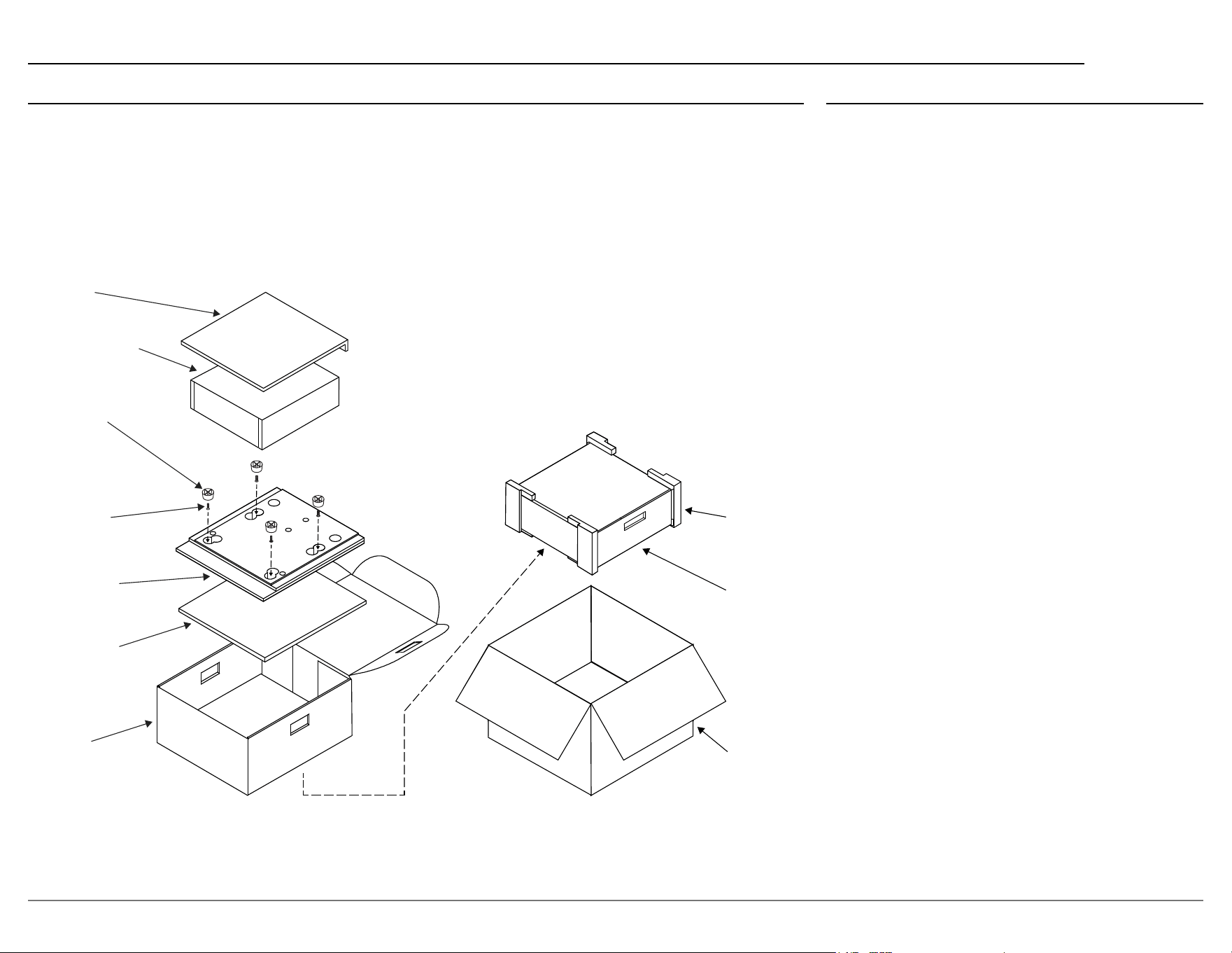
Packing Instructions
In the event it is necessary to repack the equipment
for shipment, the equipment must be packed exactly
as shown below.
It is very important that the four plastic feet are
attached to the bottom of the equipment. This
will ensure the proper equipment location on
the bottom pad. Failure to do this will result in
shipping damage.
Use the original shipping carton and interior parts
only if they are all in good serviceable condition.
If a shipping carton or any of the interior part(s)
are needed, please call or write Customer Service
Department of McIntosh Laboratory. Refer to page
2. Please see the Part List on the right for the correct
part numbers.
Part List
Qty Part Number Description
1 033838 Shipping carton
2 034669 End caps
1 033836 Inside carton
2 033725 Top / Filler pad
1 034576 Bottom pad
4 017937 Plastic feet
4 024036 Foot pads
4 400159 #10-32 x 3/4” screws
4 404080 #10 Flat washers
TOP PAD
UNIT WITH
(4) FEET ON
BOTTOM COVER
10-32 X 3/4”
SCREW WITH
WASHER (4)
BOTTOM PAD
INSIDE
CARTON
PLASTIC
FOOT WITH
PAD (4)
END CAP
INSIDE
CARTON
SHIPPING
CARTON
FILLER PAD

© 2024 McIntosh Laboratory, Inc.
McIntosh Part No. 24130300
The continuous improvement of its products is the policy of McIntosh Laboratory Incorporated
who reserve the right to improve design without notice. The MIP200 is designed to employ non-
McIntosh-provided services some of which require separate customer subscriptions and some of
which do not, as part of the Product’s functionality. Because McIntosh cannot control the provid-
ers of such services or the services themselves, the owner of the Product therefore assumes all
risks related to the use of services provided by anyone other than McIntosh itself. McIntosh can-
not and does not warrant against, and shall have no liability of any kind for any of the following
that are attributable to non-McIntosh providers or services: (i) interruption, discontinuance, or
other unsatisfactory performance of service; (ii) reduced Product functionality that is so attribut-
able; or (iii) any other loss or damage of any kind that is so attributable.
Printed in the U.S.A.
McIntosh Laboratory, Inc.
2 Chambers Street
Binghamton, NY 13903
www.mcintoshlabs.com