
EN
INSTALLATION MANUAL
USER AND MAINTENANCE MANUAL
FREESTANDING DUAL FUEL RANGES, GAS WORKTOP,
ELECTRIC MANUAL CLEAN OVEN MODEL
www.bertazzoni.com

2

FROM THE DESK OF OUR PRESIDENT
Dear new owner of a Bertazzoni appliance,
I want to thank you for choosing one of our beautiful products for your home.
My family started manufacturing kitchen appliances in Italy in 1882, building a
reputation for quality of engineering and passion for good food.
Today, our products stand out because of their unique blend of authentic Italian
design and superior appliance technology. It is our mission to make products that
function perfectly and bring joy to their owners.
By making beautiful products we respond to our customers’ flair for good design. By
making them versatile and easy-to-use, cooking with Bertazzoni becomes a real
pleasure.
This manual will help you learn to use and care for your Bertazzoni appliance in the
safest and most effective way, so that it can give you the highest satisfaction for
years to come.
Enjoy!
Paolo Bertazzoni
President
3

4

USER MANUAL VALIDITY
The following manual is valid for all the product codes mentioned below:
• MAS486ATFEMNEV
• MAS486ATFEMBIV
• MAS486GDFMXV
• MAS366BCFGMXTLP
5

6
CONTENTS
INSTALLATION MANUAL . . . . . . . . . . . . . . . . . . . . . . . . . . . . . . . . . . . . . . . . . . . . . . . . . . . . . . . . . . . . . . . . . . . . . . . . . . . 9
WARNINGS . . . . . . . . . . . . . . . . . . . . . . . . . . . . . . . . . . . . . . . . . . . . . . . . . . . . . . . . . . . . . . . . . . . . . . . . . . . . . . . . . . 9
DATA RATING LABEL . . . . . . . . . . . . . . . . . . . . . . . . . . . . . . . . . . . . . . . . . . . . . . . . . . . . . . . . . . . . . . . . . . . . . 10
BEFORE INSTALLATION . . . . . . . . . . . . . . . . . . . . . . . . . . . . . . . . . . . . . . . . . . . . . . . . . . . . . . . . . . . . . . . . . . . . . . 11
TYPE OF GAS . . . . . . . . . . . . . . . . . . . . . . . . . . . . . . . . . . . . . . . . . . . . . . . . . . . . . . . . . . . . . . . . . . . . . . . . . . . 11
GAS PRESSURE . . . . . . . . . . . . . . . . . . . . . . . . . . . . . . . . . . . . . . . . . . . . . . . . . . . . . . . . . . . . . . . . . . . . . . . . . 11
ROOM VENTILATION . . . . . . . . . . . . . . . . . . . . . . . . . . . . . . . . . . . . . . . . . . . . . . . . . . . . . . . . . . . . . . . . . . . . . 11
VENTILATION PREPARATION . . . . . . . . . . . . . . . . . . . . . . . . . . . . . . . . . . . . . . . . . . . . . . . . . . . . . . . . . . . . . . . . . . 12
SELECT HOOD AND BLOWER MODELS . . . . . . . . . . . . . . . . . . . . . . . . . . . . . . . . . . . . . . . . . . . . . . . . . . . . . 12
HOOD PLACEMENT . . . . . . . . . . . . . . . . . . . . . . . . . . . . . . . . . . . . . . . . . . . . . . . . . . . . . . . . . . . . . . . . . . . . . . 12
CONSIDER MAKE-UP AIR . . . . . . . . . . . . . . . . . . . . . . . . . . . . . . . . . . . . . . . . . . . . . . . . . . . . . . . . . . . . . . . . . 12
SPECIFICATIONS . . . . . . . . . . . . . . . . . . . . . . . . . . . . . . . . . . . . . . . . . . . . . . . . . . . . . . . . . . . . . . . . . . . . . . . . . . . . 13
CLEARANCE DIMENSIONS . . . . . . . . . . . . . . . . . . . . . . . . . . . . . . . . . . . . . . . . . . . . . . . . . . . . . . . . . . . . . . . . . . . . 14
INSTALLATION ADJACENT TO KITCHEN CABINETS . . . . . . . . . . . . . . . . . . . . . . . . . . . . . . . . . . . . . . . . . . 14
CABINET . . . . . . . . . . . . . . . . . . . . . . . . . . . . . . . . . . . . . . . . . . . . . . . . . . . . . . . . . . . . . . . . . . . . . . . . . . . . . . . . 14
METAL HOOD . . . . . . . . . . . . . . . . . . . . . . . . . . . . . . . . . . . . . . . . . . . . . . . . . . . . . . . . . . . . . . . . . . . . . . . . . . . . 14
INSTALLATION REQUIREMENTS . . . . . . . . . . . . . . . . . . . . . . . . . . . . . . . . . . . . . . . . . . . . . . . . . . . . . . . . . . . . . . . 15
ELECTRICAL . . . . . . . . . . . . . . . . . . . . . . . . . . . . . . . . . . . . . . . . . . . . . . . . . . . . . . . . . . . . . . . . . . . . . . . . . . . . 15
GAS . . . . . . . . . . . . . . . . . . . . . . . . . . . . . . . . . . . . . . . . . . . . . . . . . . . . . . . . . . . . . . . . . . . . . . . . . . . . . . . . . . . . 15
ELECTRICAL CONNECTION . . . . . . . . . . . . . . . . . . . . . . . . . . . . . . . . . . . . . . . . . . . . . . . . . . . . . . . . . . . . . . . . . . . 16
ELECTRICAL CONNECTION TABLE . . . . . . . . . . . . . . . . . . . . . . . . . . . . . . . . . . . . . . . . . . . . . . . . . . . . . . . . . 16
FOUR WIRES CONNECTION . . . . . . . . . . . . . . . . . . . . . . . . . . . . . . . . . . . . . . . . . . . . . . . . . . . . . . . . . . . . . . . 17
METAL CONDUIT CONNECTION - OPTION . . . . . . . . . . . . . . . . . . . . . . . . . . . . . . . . . . . . . . . . . . . . . . . . . . . 18
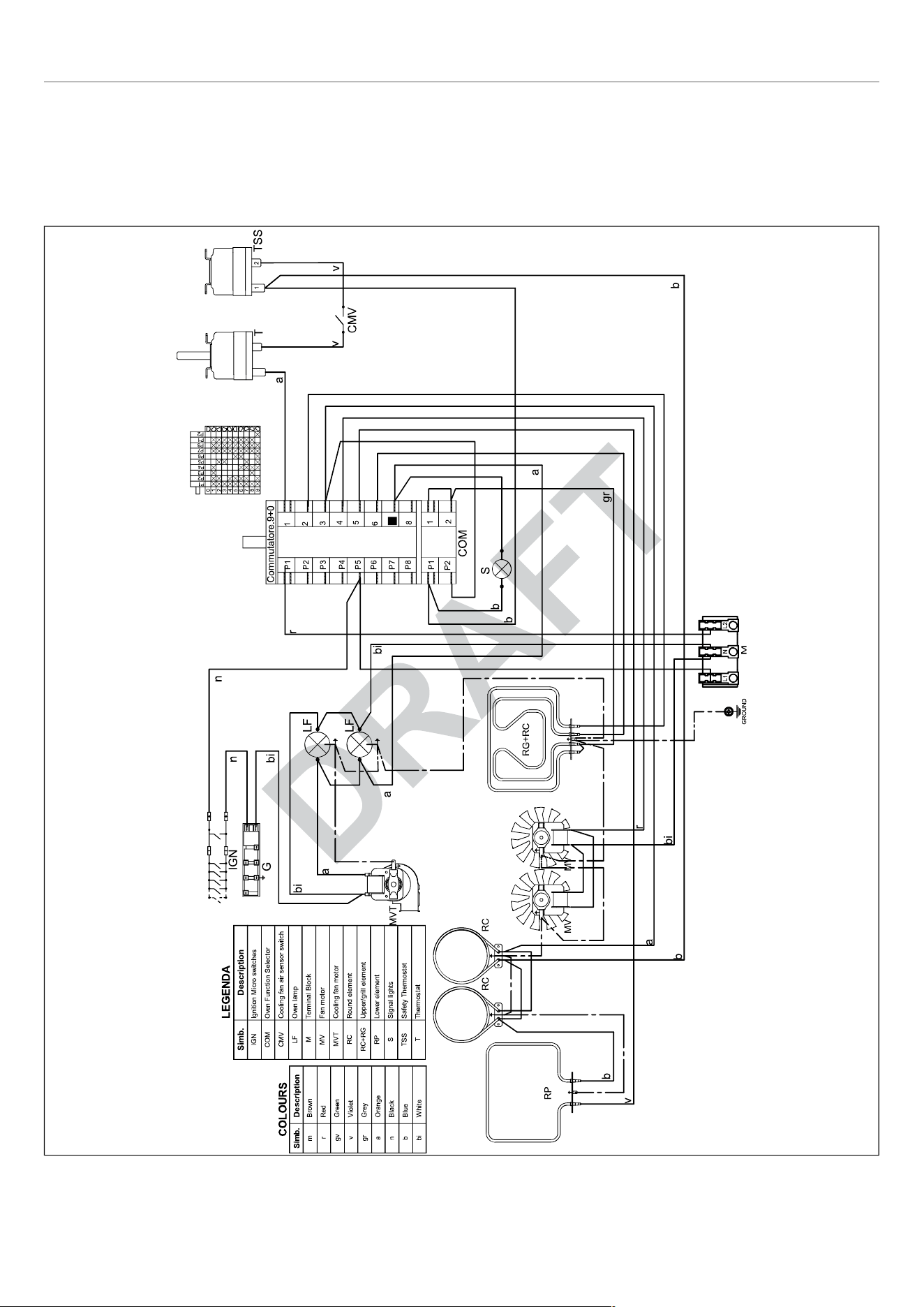
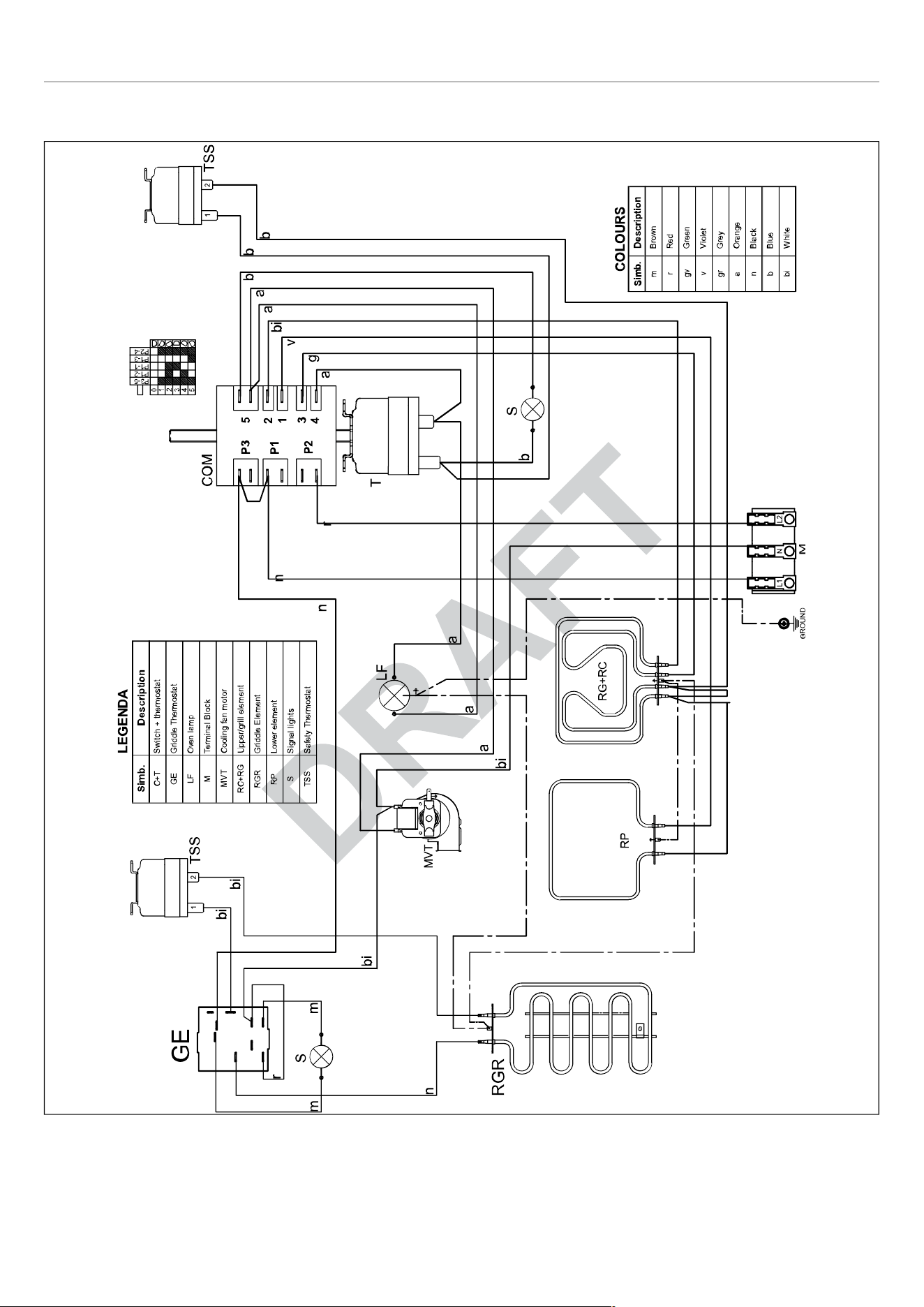
WIRING DIAGRAM . . . . . . . . . . . . . . . . . . . . . . . . . . . . . . . . . . . . . . . . . . . . . . . . . . . . . . . . . . . . . . . . . . . . . . . . 20
GAS CONNECTION . . . . . . . . . . . . . . . . . . . . . . . . . . . . . . . . . . . . . . . . . . . . . . . . . . . . . . . . . . . . . . . . . . . . . . . . . . . 22
MANUAL SHUT-OFF VALVE . . . . . . . . . . . . . . . . . . . . . . . . . . . . . . . . . . . . . . . . . . . . . . . . . . . . . . . . . . . . . . . . 22
FLEXIBLE CONNECTIONS . . . . . . . . . . . . . . . . . . . . . . . . . . . . . . . . . . . . . . . . . . . . . . . . . . . . . . . . . . . . . . . . . 22
PRESSURE TEST-POINT STOPPER VALVE . . . . . . . . . . . . . . . . . . . . . . . . . . . . . . . . . . . . . . . . . . . . . . . . . . 22
PRESSURE REGULATOR . . . . . . . . . . . . . . . . . . . . . . . . . . . . . . . . . . . . . . . . . . . . . . . . . . . . . . . . . . . . . . . . . 23
INSTALLATION . . . . . . . . . . . . . . . . . . . . . . . . . . . . . . . . . . . . . . . . . . . . . . . . . . . . . . . . . . . . . . . . . . . . . . . . . . . . . . . 24
APPLIANCE INSTALLATION . . . . . . . . . . . . . . . . . . . . . . . . . . . . . . . . . . . . . . . . . . . . . . . . . . . . . . . . . . . . . . . . 24
REMOVING THE OVEN DOOR . . . . . . . . . . . . . . . . . . . . . . . . . . . . . . . . . . . . . . . . . . . . . . . . . . . . . . . . . . . . . 24
INSTALLING THE LEGS . . . . . . . . . . . . . . . . . . . . . . . . . . . . . . . . . . . . . . . . . . . . . . . . . . . . . . . . . . . . . . . . . . . 25
INSTALLING THE WORKTOP FRONTGUARD . . . . . . . . . . . . . . . . . . . . . . . . . . . . . . . . . . . . . . . . . . . . . . . . . 25
INSTALLING THE ISLAND TRIM . . . . . . . . . . . . . . . . . . . . . . . . . . . . . . . . . . . . . . . . . . . . . . . . . . . . . . . . . . . . 26
INSTALLING BACKGUARD (OPTIONAL) . . . . . . . . . . . . . . . . . . . . . . . . . . . . . . . . . . . . . . . . . . . . . . . . . . . . . 26
INSTALLING THE ANTI-TIP DEVICES . . . . . . . . . . . . . . . . . . . . . . . . . . . . . . . . . . . . . . . . . . . . . . . . . . . . . . . . . . . 27
ANTI-TIP BRACKETS . . . . . . . . . . . . . . . . . . . . . . . . . . . . . . . . . . . . . . . . . . . . . . . . . . . . . . . . . . . . . . . . . . . . . 27
ANTI/TILT CHAIN . . . . . . . . . . . . . . . . . . . . . . . . . . . . . . . . . . . . . . . . . . . . . . . . . . . . . . . . . . . . . . . . . . . . . . . . . 27
GAS CONVERSION . . . . . . . . . . . . . . . . . . . . . . . . . . . . . . . . . . . . . . . . . . . . . . . . . . . . . . . . . . . . . . . . . . . . . . . . . . 29
STEP 1: PRESSURE REGULATOR . . . . . . . . . . . . . . . . . . . . . . . . . . . . . . . . . . . . . . . . . . . . . . . . . . . . . . . . . . 29
STEP 2: SURFACE BURNERS . . . . . . . . . . . . . . . . . . . . . . . . . . . . . . . . . . . . . . . . . . . . . . . . . . . . . . . . . . . . . . 30
STEP 3: VISUAL CHECKS . . . . . . . . . . . . . . . . . . . . . . . . . . . . . . . . . . . . . . . . . . . . . . . . . . . . . . . . . . . . . . . . . 30
STEP 4: MINIMUM FLAME ADJUSTMENT . . . . . . . . . . . . . . . . . . . . . . . . . . . . . . . . . . . . . . . . . . . . . . . . . . . . 31
INSTALLATION CHECKLIST . . . . . . . . . . . . . . . . . . . . . . . . . . . . . . . . . . . . . . . . . . . . . . . . . . . . . . . . . . . . . . . . . . . 32
FINAL PREPARATION . . . . . . . . . . . . . . . . . . . . . . . . . . . . . . . . . . . . . . . . . . . . . . . . . . . . . . . . . . . . . . . . . . . . . . . . . 33
BERTAZZONI SERVICE . . . . . . . . . . . . . . . . . . . . . . . . . . . . . . . . . . . . . . . . . . . . . . . . . . . . . . . . . . . . . . . . . . . . . . . 34
USER AND MAINTENANCE MANUAL . . . . . . . . . . . . . . . . . . . . . . . . . . . . . . . . . . . . . . . . . . . . . . . . . . . . . . . . . . . . . . . 35
WARNINGS . . . . . . . . . . . . . . . . . . . . . . . . . . . . . . . . . . . . . . . . . . . . . . . . . . . . . . . . . . . . . . . . . . . . . . . . . . . . . . . . . 35
TO PREVENT FIRE OR SMOKE DAMAGE . . . . . . . . . . . . . . . . . . . . . . . . . . . . . . . . . . . . . . . . . . . . . . . . . . . . 35
IN CASE OF FIRE . . . . . . . . . . . . . . . . . . . . . . . . . . . . . . . . . . . . . . . . . . . . . . . . . . . . . . . . . . . . . . . . . . . . . . . . . 35
CHILD SAFETY . . . . . . . . . . . . . . . . . . . . . . . . . . . . . . . . . . . . . . . . . . . . . . . . . . . . . . . . . . . . . . . . . . . . . . . . . . 35
COOKING SAFETY . . . . . . . . . . . . . . . . . . . . . . . . . . . . . . . . . . . . . . . . . . . . . . . . . . . . . . . . . . . . . . . . . . . . . . . 36
RECOMMENDED UTENSILS . . . . . . . . . . . . . . . . . . . . . . . . . . . . . . . . . . . . . . . . . . . . . . . . . . . . . . . . . . . . . . . 36
INDUCTION COOKING SURFACES . . . . . . . . . . . . . . . . . . . . . . . . . . . . . . . . . . . . . . . . . . . . . . . . . . . . . . . . . 37
OVEN HEATING ELEMENTS . . . . . . . . . . . . . . . . . . . . . . . . . . . . . . . . . . . . . . . . . . . . . . . . . . . . . . . . . . . . . . . 37
CLEANING SAFETY . . . . . . . . . . . . . . . . . . . . . . . . . . . . . . . . . . . . . . . . . . . . . . . . . . . . . . . . . . . . . . . . . . . . . . 37
POWER FAILURE WARNING . . . . . . . . . . . . . . . . . . . . . . . . . . . . . . . . . . . . . . . . . . . . . . . . . . . . . . . . . . . . . . . 37
ROOM VENTILATION . . . . . . . . . . . . . . . . . . . . . . . . . . . . . . . . . . . . . . . . . . . . . . . . . . . . . . . . . . . . . . . . . . . . . 37

7
CONTENTS
ELECTRICAL SHOCK HAZARD . . . . . . . . . . . . . . . . . . . . . . . . . . . . . . . . . . . . . . . . . . . . . . . . . . . . . . . . . . . . . 37
BURN HAZARD . . . . . . . . . . . . . . . . . . . . . . . . . . . . . . . . . . . . . . . . . . . . . . . . . . . . . . . . . . . . . . . . . . . . . . . . . . 38
WARNING-TIPPING HAZARD . . . . . . . . . . . . . . . . . . . . . . . . . . . . . . . . . . . . . . . . . . . . . . . . . . . . . . . . . . . . . . 38
WORKTOP AND KNOBS LAYOUT . . . . . . . . . . . . . . . . . . . . . . . . . . . . . . . . . . . . . . . . . . . . . . . . . . . . . . . . . . . . . . . 39
GAS COOKTOP . . . . . . . . . . . . . . . . . . . . . . . . . . . . . . . . . . . . . . . . . . . . . . . . . . . . . . . . . . . . . . . . . . . . . . . . . . . . . . 40
BURNER CAPS AND GRATES . . . . . . . . . . . . . . . . . . . . . . . . . . . . . . . . . . . . . . . . . . . . . . . . . . . . . . . . . . . . . . 40
MAKING SURE THE FLAME IS OPTIMAL . . . . . . . . . . . . . . . . . . . . . . . . . . . . . . . . . . . . . . . . . . . . . . . . . . . . . 40
USING THE GAS BURNERS . . . . . . . . . . . . . . . . . . . . . . . . . . . . . . . . . . . . . . . . . . . . . . . . . . . . . . . . . . . . . . . 41
USING THE POWER BURNERS . . . . . . . . . . . . . . . . . . . . . . . . . . . . . . . . . . . . . . . . . . . . . . . . . . . . . . . . . . . . 41
GAS SHUT-OFF SAFETY - THERMOCOUPLE . . . . . . . . . . . . . . . . . . . . . . . . . . . . . . . . . . . . . . . . . . . . . . . . . 41
USING SPECIALTY COOKWARE . . . . . . . . . . . . . . . . . . . . . . . . . . . . . . . . . . . . . . . . . . . . . . . . . . . . . . . . . . . 42
GAS BURNER DIMENSIONS AND RECOMMENDED PAN SIZE . . . . . . . . . . . . . . . . . . . . . . . . . . . . . . . . . . 42
ELECTRIC GRIDDLE . . . . . . . . . . . . . . . . . . . . . . . . . . . . . . . . . . . . . . . . . . . . . . . . . . . . . . . . . . . . . . . . . . . . . . . . . 43
PREPARING THE GRIDDLE . . . . . . . . . . . . . . . . . . . . . . . . . . . . . . . . . . . . . . . . . . . . . . . . . . . . . . . . . . . . . . . . 43
SEASONING THE GRIDDLE . . . . . . . . . . . . . . . . . . . . . . . . . . . . . . . . . . . . . . . . . . . . . . . . . . . . . . . . . . . . . . . 43
USING THE ELECTRIC GRIDDLE . . . . . . . . . . . . . . . . . . . . . . . . . . . . . . . . . . . . . . . . . . . . . . . . . . . . . . . . . . . 43
RECOMMENDED GRIDDLE TEMPERATURES . . . . . . . . . . . . . . . . . . . . . . . . . . . . . . . . . . . . . . . . . . . . . . . . 44
ELECTRIC OVEN . . . . . . . . . . . . . . . . . . . . . . . . . . . . . . . . . . . . . . . . . . . . . . . . . . . . . . . . . . . . . . . . . . . . . . . . . . . . 45
MAIN ELECTRIC OVEN . . . . . . . . . . . . . . . . . . . . . . . . . . . . . . . . . . . . . . . . . . . . . . . . . . . . . . . . . . . . . . . . . . . 45
AUXILIARY ELECTRIC OVEN . . . . . . . . . . . . . . . . . . . . . . . . . . . . . . . . . . . . . . . . . . . . . . . . . . . . . . . . . . . . . . 47
CONDENSATION . . . . . . . . . . . . . . . . . . . . . . . . . . . . . . . . . . . . . . . . . . . . . . . . . . . . . . . . . . . . . . . . . . . . . . . . . 49
GETTING THE BEST RESULTS . . . . . . . . . . . . . . . . . . . . . . . . . . . . . . . . . . . . . . . . . . . . . . . . . . . . . . . . . . . . . 49
OVEN COOKING RECOMMENDATIONS . . . . . . . . . . . . . . . . . . . . . . . . . . . . . . . . . . . . . . . . . . . . . . . . . . . . . 49
BROILING RECOMMENDATION . . . . . . . . . . . . . . . . . . . . . . . . . . . . . . . . . . . . . . . . . . . . . . . . . . . . . . . . . . . . 50
AIR FRY RECOMMENDATIONS . . . . . . . . . . . . . . . . . . . . . . . . . . . . . . . . . . . . . . . . . . . . . . . . . . . . . . . . . . . . . 51
TROUBLESHOOTING COMMON PROBLEMS WITH OVEN COOKING . . . . . . . . . . . . . . . . . . . . . . . . . . . . 51
OVEN TEMPERATURE GAUGE . . . . . . . . . . . . . . . . . . . . . . . . . . . . . . . . . . . . . . . . . . . . . . . . . . . . . . . . . . . . . 52
TELESCOPIC GLIDES . . . . . . . . . . . . . . . . . . . . . . . . . . . . . . . . . . . . . . . . . . . . . . . . . . . . . . . . . . . . . . . . . . . . 52
KEEPING YOUR BERTAZZONI CLEAN . . . . . . . . . . . . . . . . . . . . . . . . . . . . . . . . . . . . . . . . . . . . . . . . . . . . . . . . . . 54
BURN HAZARD . . . . . . . . . . . . . . . . . . . . . . . . . . . . . . . . . . . . . . . . . . . . . . . . . . . . . . . . . . . . . . . . . . . . . . . . . . 54
THINGS TO AVOID . . . . . . . . . . . . . . . . . . . . . . . . . . . . . . . . . . . . . . . . . . . . . . . . . . . . . . . . . . . . . . . . . . . . . . . 54
CLEANING STAINLESS STEEL . . . . . . . . . . . . . . . . . . . . . . . . . . . . . . . . . . . . . . . . . . . . . . . . . . . . . . . . . . . . . 54
CLEANING PAINTED SURFACES . . . . . . . . . . . . . . . . . . . . . . . . . . . . . . . . . . . . . . . . . . . . . . . . . . . . . . . . . . . 54
CLEANING GLASS SURFACES . . . . . . . . . . . . . . . . . . . . . . . . . . . . . . . . . . . . . . . . . . . . . . . . . . . . . . . . . . . . . 54
CLEANING THE BROILER PAN . . . . . . . . . . . . . . . . . . . . . . . . . . . . . . . . . . . . . . . . . . . . . . . . . . . . . . . . . . . . . 54
CLEANING THE STAINLESS STEEL GRIDDLE . . . . . . . . . . . . . . . . . . . . . . . . . . . . . . . . . . . . . . . . . . . . . . . . 54
CLEANING THE OVEN CAVITY . . . . . . . . . . . . . . . . . . . . . . . . . . . . . . . . . . . . . . . . . . . . . . . . . . . . . . . . . . . . . 54
CLEANING OVEN RACKS AND SUPPORTS . . . . . . . . . . . . . . . . . . . . . . . . . . . . . . . . . . . . . . . . . . . . . . . . . . 54
SIMPLE MAINTENANCE . . . . . . . . . . . . . . . . . . . . . . . . . . . . . . . . . . . . . . . . . . . . . . . . . . . . . . . . . . . . . . . . . . . . . . 55
REPLACING OVEN LIGHTS . . . . . . . . . . . . . . . . . . . . . . . . . . . . . . . . . . . . . . . . . . . . . . . . . . . . . . . . . . . . . . . . 55
TROUBLESHOOTING . . . . . . . . . . . . . . . . . . . . . . . . . . . . . . . . . . . . . . . . . . . . . . . . . . . . . . . . . . . . . . . . . . . . . . . . . 57
THE OVEN WILL NOT OPERATE . . . . . . . . . . . . . . . . . . . . . . . . . . . . . . . . . . . . . . . . . . . . . . . . . . . . . . . . . . . . 57
THE SURFER BURNERS WILL NOT IGNITE . . . . . . . . . . . . . . . . . . . . . . . . . . . . . . . . . . . . . . . . . . . . . . . . . . 57
THE BURNER IGNITES BUT SWITCHES OFF WHEN THE KNOB IS RELEASED . . . . . . . . . . . . . . . . . . . 57
THE IGNITION CANDLES ARE SPARKING CONTINUOUSLY . . . . . . . . . . . . . . . . . . . . . . . . . . . . . . . . . . . . 57
THE CONTROL KNOBS ARE GETTING TOO HOT . . . . . . . . . . . . . . . . . . . . . . . . . . . . . . . . . . . . . . . . . . . . . 57
A CONTROL KNOB IS LOOSE ON ITS SHAFT . . . . . . . . . . . . . . . . . . . . . . . . . . . . . . . . . . . . . . . . . . . . . . . . 57
FOOD IS COOKING TOO QUICKLY . . . . . . . . . . . . . . . . . . . . . . . . . . . . . . . . . . . . . . . . . . . . . . . . . . . . . . . . . . 57
FOOD IS NOT COOKING EVENLY . . . . . . . . . . . . . . . . . . . . . . . . . . . . . . . . . . . . . . . . . . . . . . . . . . . . . . . . . . 57
GRILLING IN THE OVEN IS SLOW . . . . . . . . . . . . . . . . . . . . . . . . . . . . . . . . . . . . . . . . . . . . . . . . . . . . . . . . . . 57
THE FAN CONTINUES TO RUN AFTER THE OVEN IS SWITCHED OFF . . . . . . . . . . . . . . . . . . . . . . . . . . . 57
CONDENSATION FORMS IN THE OVEN . . . . . . . . . . . . . . . . . . . . . . . . . . . . . . . . . . . . . . . . . . . . . . . . . . . . . 57
SMOKE IS GENERATED IN THE OVEN . . . . . . . . . . . . . . . . . . . . . . . . . . . . . . . . . . . . . . . . . . . . . . . . . . . . . . 57
CUSTOMER CARE . . . . . . . . . . . . . . . . . . . . . . . . . . . . . . . . . . . . . . . . . . . . . . . . . . . . . . . . . . . . . . . . . . . . . . . . . . . 58

8
WARNINGS
To ensure proper and safe operation, the appliance must
be properly installed and grounded by a qualified technician.
DO NOT attempt to adjust, repair, service, or replace any
part of your appliance unless it is specifically recommended
in this manual. All other servicing should be referred to a
qualified servicer.
Have the installer show you the location of the gas shutoff
valve and how to shut it off in an emergency. A certified
technician is required for any adjustments or conversions to
Natural or LP gas.
FOR THE INSTALLER: Before installing the Bertazzoni
appliance, please read these instructions carefully. This
appliance shall be installed in accordance with the
manufacturer’s installation instructions.
IMPORTANT
Leave these instructions with the owner,
who should save them for local inspector’s
use and for future reference. DO NOT
remove permanently affixed labels,
warnings, or plates from product. This may
void the warranty.
Installation must conform with all local codes. In the
absence of codes:
• United States: installation must conform with the
National Fuel Gas Code ANSI Z223.1 INFPA54.
• Massachusetts: All gas products must be installed by a
“Massachusetts” licensed plumber or gasfitter. A “T” type
handle manual valve must be installed in the gas supply
line to the appliance.
• Canada: Installation must be in accordance with the
current CAN/CGA B149.1 & 2 Gas Installation codes
and/or local codes. Electrical installation must be in
accordance with the current CSA C22.1 Canadian
Electrical Codes Part 1 and/or local codes.
This range is NOT designed for installation in manufactured
(mobile) homes or recreational park trailers.
DO NOT install this range outdoors.
This appliance must be properly grounded. Grounding
reduces the risk of electric shock by providing a safe
pathway for electric current in the event of a short circuit.
WARNING
To avoid risk of property damage, personal
injury or death; follow information in this
manual exactly to prevent a fire or
explosion.
WARNING
If the information in these instructions is
not followed exactly, a fire or explosion
may result causing property damage,
personal injury or death.
• Do not store or use gasoline or other
flammable vapors and liquid in the
vicinity of this or any other appliance.
• WHAT TO DO IF YOU SMELL GAS
• Do not try to light any appliance.
• Do not touch any electrical switch.
• Do not use any phone in your building.
• Immediately call your gas supplier
from a neighbor’s phone. Follow the
gas supplier’s instructions.
• If you cannot reach your gas
suppliers, call the fire department.
• Installation and service must be
performed by a qualified installer,
service agency or the gas supplier.
NOTE
Installation and service must be performed
by a qualified installer, service agency or
the gas supplier.
DANGER
ELECTRIC SHOCK HAZARD!!!
To avoid risk of electrical shock, personal
injury or death, verify that the appliance has
been properly grounded in accordance with
local codes or in absence of codes, with the
National Electrical Code (NEC). ANSI/
NFPA 70 - latest edition.
DANGER
GAS LEAK HAZARD!!!
To avoid risk of personal injury or death,
leak-testing of the appliance must be
conducted according to the manufacturer’s
instructions. Before placing appliance in
operation, always check for gas leaks with
water and soap solution.
DO NOT USE AN OPEN FLAME TO
CHECK FOR GAS LEAKS.
9
WARNINGS
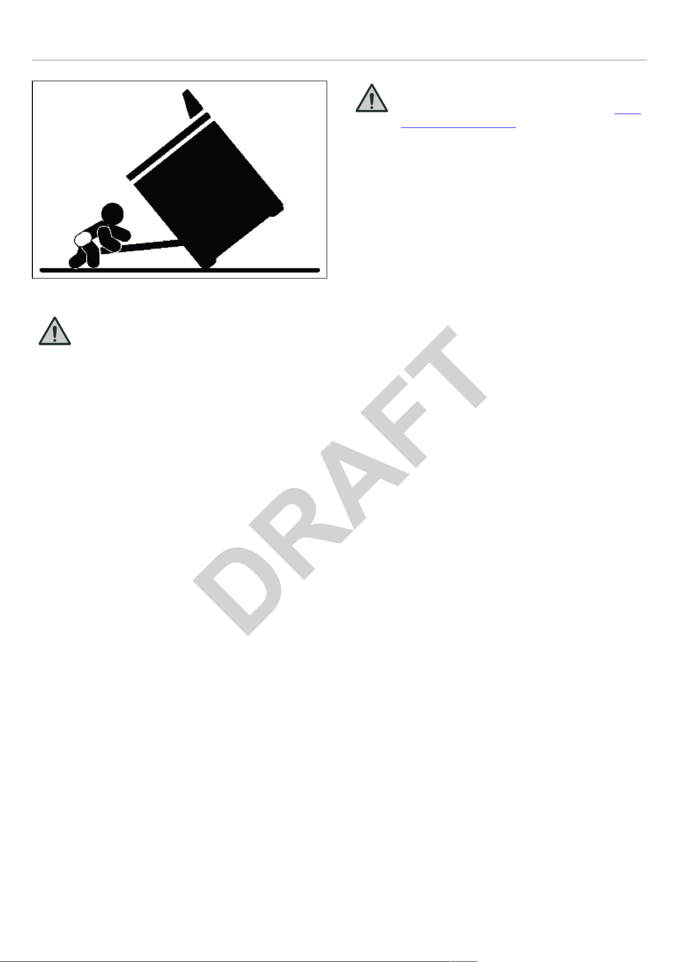
Fig. 1
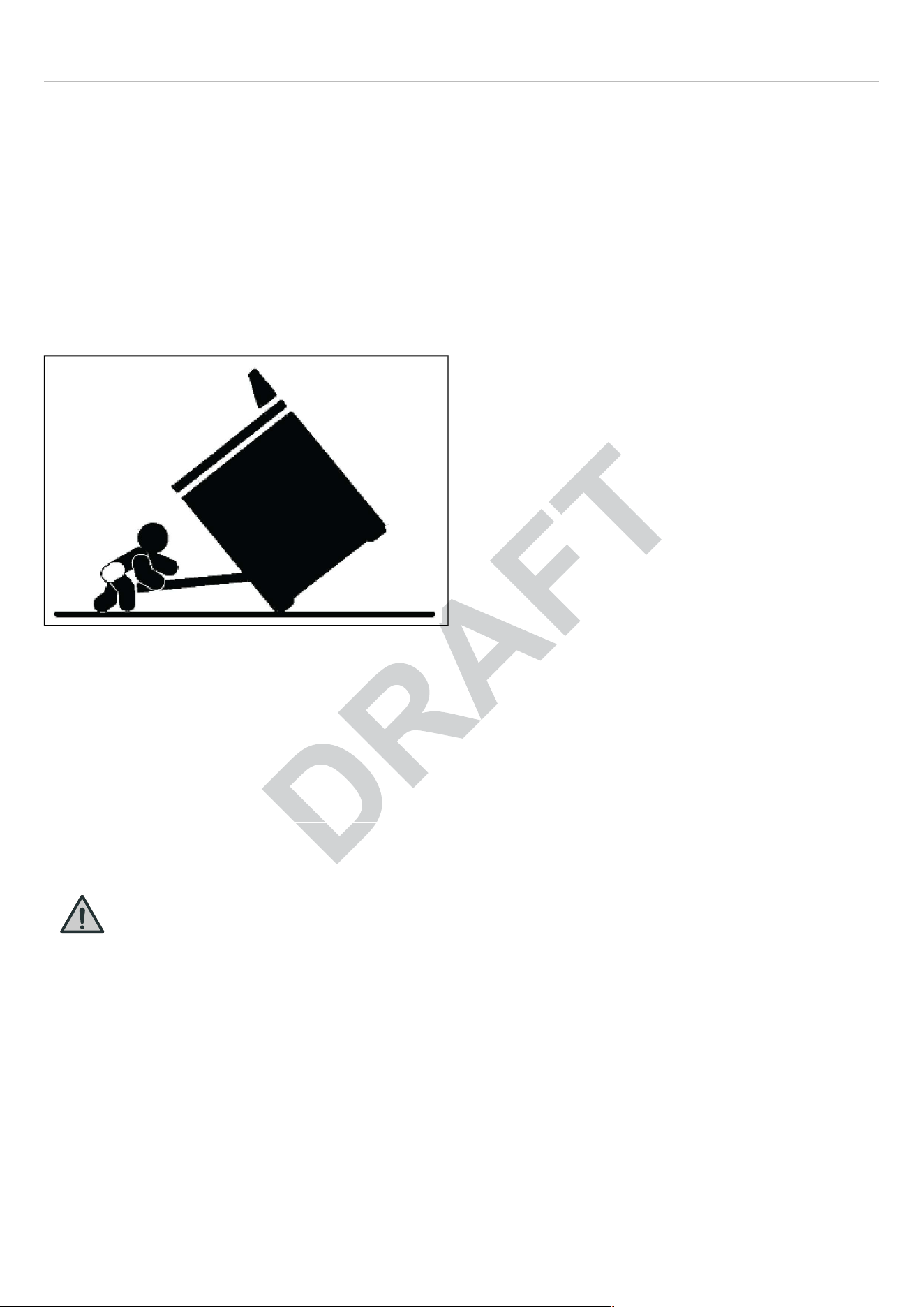
WARNING
Warning-tipping hazard
A child or adult can tip over the range and
be killed.
Install the anti-tip device to the structure
and/or the range. Verify the anti-tip device
has been properly installed and engaged.
Engage the range to the anti-tip device by anti-tip brackets
or anti-tip chain (see installing the anti- tip device chapter).
Ensure the anti-tip device is re-engaged when the range is
moved.
Re-engage the anti-tip device if the range is moved. Do not
operate the range without the anti-tip device in place and
engaged.
See anti-tip device installation instructions for details.
Failure to do so can result in death or serious burns to
children or adults.
DO NOT lift the range by the oven door’s handle, as this
may damage the door hinges and cause the door to fit
incorrectly.
DO NOT lift the appliance by the range’s control panel.
The unit is heavy and should be handled accordingly.
Proper safety equipment such as gloves and adequate
manpower of at least two people must be used in moving
the range to avoid injury and to avoid damage to the unit or
the floor. Rings, watches, and any other loose items that
may damage the unit or otherwise might become entangled
with the unit should be removed.
Hidden surfaces may have sharp edges. Use caution when
reaching behind or under appliance.
DO NOT use a hand truck or appliance dolly on the back or
front of the unit. Handle from the side only.
WARNING
Cancer and Reproductive Harm — www.
P65Warnings.ca.gov.
DATA RATING LABEL
The data rating label shows the model and serial number of
the range. It is located under the control panel and in the
last page of this manual.
10

BEFORE INSTALLATION
• This appliance shall only be installed by an authorized
professional.
• This appliance shall be installed in accordance with the
manufacturer’s installation instructions.
• This appliance must be installed in accordance with the
norms & standards of the country where it will be
installed.
• The installation of this appliance must conform to local
codes and ordinances. In the absence of local codes,
installations must conform to American National
Standards, National Fuel Gas Code ANSI Z223.1 –
latest edition/NFPA 54 or B149.1.
• The appliance, when installed, must be electrically
grounded in accordance with local codes or, in the
absence of local codes, with the National Electrical Code,
ANSI/NFPA 70.
If local codes permit, a flexible metal appliance connection
conduit with the new AGA or CGA certified design, max. 5
feet (1.5 m) long, ½″ I. D. is recommended for connecting
this appliance to the gas supply line. Do not bend or
damage the flexible connector when moving the appliance.
This appliance must be used with the pressure
regulator provided.
The regulator shall be properly installed in order to be
accessible when the appliance is installed in its final
location. The pressure regulator must be set for the type of
gas to be used. The pressure regulator has ½″ female pipe
thread. The appropriate fitting must be determined based
on the size of your gas supply line, the flexible metal
connector and the shutoff valve.
The appliance must be isolated from the gas supply piping
system by closing its individual manual shutoff valve during
any pressure testing of the gas supply piping system at test
pressures equal to or less than 1/2 PSI (13.8″ w. c. or 3.5
kPa).
All opening and holes in the wall and floor, back and under
the appliance shall be sealed before installation of the
appliance.
A manual valve shall be installed in an accessible location
in the gas line external to the appliance for the purpose of
turning on or shutting off gas to the appliance.
TYPE OF GAS
This range can be used with Natural or LP/Propane gas.
The range is shipped from the factory for use with the gas
indicated on the rating label positioned on the lower face of
the control panel and in the last page of this manual. A step
by step conversion procedure is also included in this
manual and in each conversion kit.
GAS PRESSURE
The maximum inlet gas supply pressure incoming to the
gas appliance pressure regulator is 1/2 PSI (13.8″ iwc or
3.5 kPa). The minimum gas supply pressure for checking
the regulator setting shall be at least 1″ iwc (249 Pa) above
the inlet specified manifold pressure to the appliance; this
operating pressure is 4″ iwc (1.00 kPa) for Natural Gas and
10″ iwc (2.50 kPa) for LP Gas.
ROOM VENTILATION
An exhaust fan may be used with the appliance; in each
case it shall be installed in conformity with the appropriate
national and local standards. Exhaust hood operation may
affect other vented appliances; in each case it shall be
installed in conformity with the appropriate national and
local standards.
WARNING
This appliance should not be installed with
a ventilation system that directs air in a
downward direction toward the range. This
type of ventilation system may cause
ignition and combustion problems with the
appliance resulting in personal injury,
property damage, or unintended operation.
Ventilating systems that direct the air
upwards do not have any restriction.
Do not use aerosol sprays in the vicinity of this
appliance while it is in operation.
11

VENTILATION PREPARATION
This range will best perform when installed with Bertazzoni
exhaust hoods. These hoods have been designed to work
in conjunction with the Bertazzoni range and have the
same finish for a perfect look.
Before installation of the exhaust hood, consult local or
regional building and installation codes for additional
specific clearance requirements. Refer to the range hood
installation instructions provided by the manufacturer for
additional information.
SELECT HOOD AND BLOWER MODELS
• For wall installations, the hood should be equal or larger
width than the range. Where space permits, a hood
larger than the range may be desirable for improved
ventilation performance.
• For island installations, the hood width should overhang
the range by a minimum of 3″ (76 mm) on each side.
HOOD PLACEMENT
• For best removal of smoke and odors, the lower edge of
the hood should be installed between 25 1/2″ (65 cm)
and 31 1/2″ (80 cm) above the range cooking surface.
• If the hood contains any combustible materials (i. e. a
wood covering), it must be installed at a minimum of 36″
(914 mm) above the cooking surface.
CONSIDER MAKE-UP AIR
Due to the high volume of ventilation air, a source of
outside replacement air is recommended. This is
particularly important for tightly sealed and insulated homes.
A qualified heating and ventilating contractor should be
consulted.
12
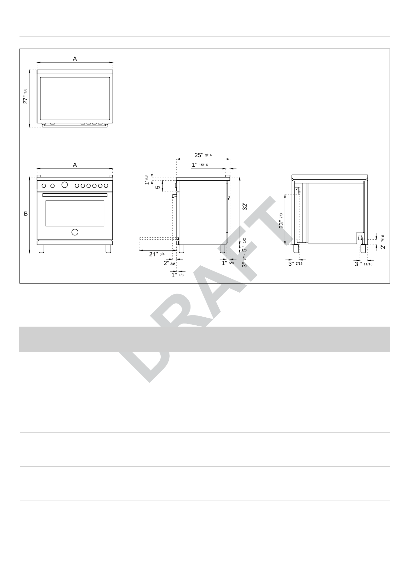
SPECIFICATIONS
Fig. 2
• A 48″
• B 37″½ MAX
BURNER
INJEC-
TOR
GAS
PRES-
SURE
MAX RATE MIN RATE BY–PASS
diam.[mm] Type [iwc] [Btu/hr] [W] [Btu/hr] [W] diam.[mm]
Auxiliary
0.90
0.54
NG
LP
(Propane)
4″
10″
3,500
3,300
1,025
967
900
900
264
264
Regulated
0.29
Semi-rapid
1.18
0.70
NG
LP
(Propane)
4″
10″
5,900
5,500
1,729
1,611
1,500
1,500
439
439
Regulated
0.36
Rapid
1.55
0.92
NG
LP
(Propane)
4″
10″
10,400
9,500
3,047
2,783
2,500
2,500
732
732
Regulated
0.47
Dual
burner
0.80+2.10
0.50+1.20
NG
LP
(Propane)
4″
10″
19,000
19,000
5,567
5,567
1,300
1,300
381
381
Regulated
0.34/0.65
See use and care manual for the layout of the surface burners of your range
A
27''
/8
1''
15/16
25''
/16
2''
1''
5/8
32''
3''
3/4
- 5''
1/2
5''
1''
5/8
1''
1/8
''
/
23''
7/8
3''
7/16
3 ''
11/16
2''
7/16
A
B
13
CLEARANCE DIMENSIONS
INSTALLATION ADJACENT TO KITCHEN
CABINETS
This range may be installed directly adjacent to existing
countertop high cabinets (36″ or 91.5 cm from the floor).
For the best look, the worktop should be level with the
cabinet countertop. This can be accomplished by raising
the unit using the adjustment spindles on the legs.
CAUTION
The range CANNOT be installed directly
adjacent to kitchen walls, tall cabinets, tall
appliances, or other vertical surfaces above
36″ (91.4 cm) high. The minimum side
clearance in such cases is 6″ (15.2 cm).
Wall cabinets with minimum side clearance must be
installed 18″ (45.7 cm) above the countertop with
countertop height between 35 ½″ (90.2 cm) and 37 ¼″
(94.6 cm). The maximum depth of wall cabinets above the
range shall be 13″ (33.0 cm).
CABINET
A
48″(122 cm)
B
36″ (91.5 cm) hood with combustible materials
C 13″ (33.0 cm)
D
18″ (45.7 cm)
E
35″ 1/2 (90.2 cm) / 37″ ¼ (94.6 cm)
F
6″ (15.2 cm)
G 6″ (15.2 cm)
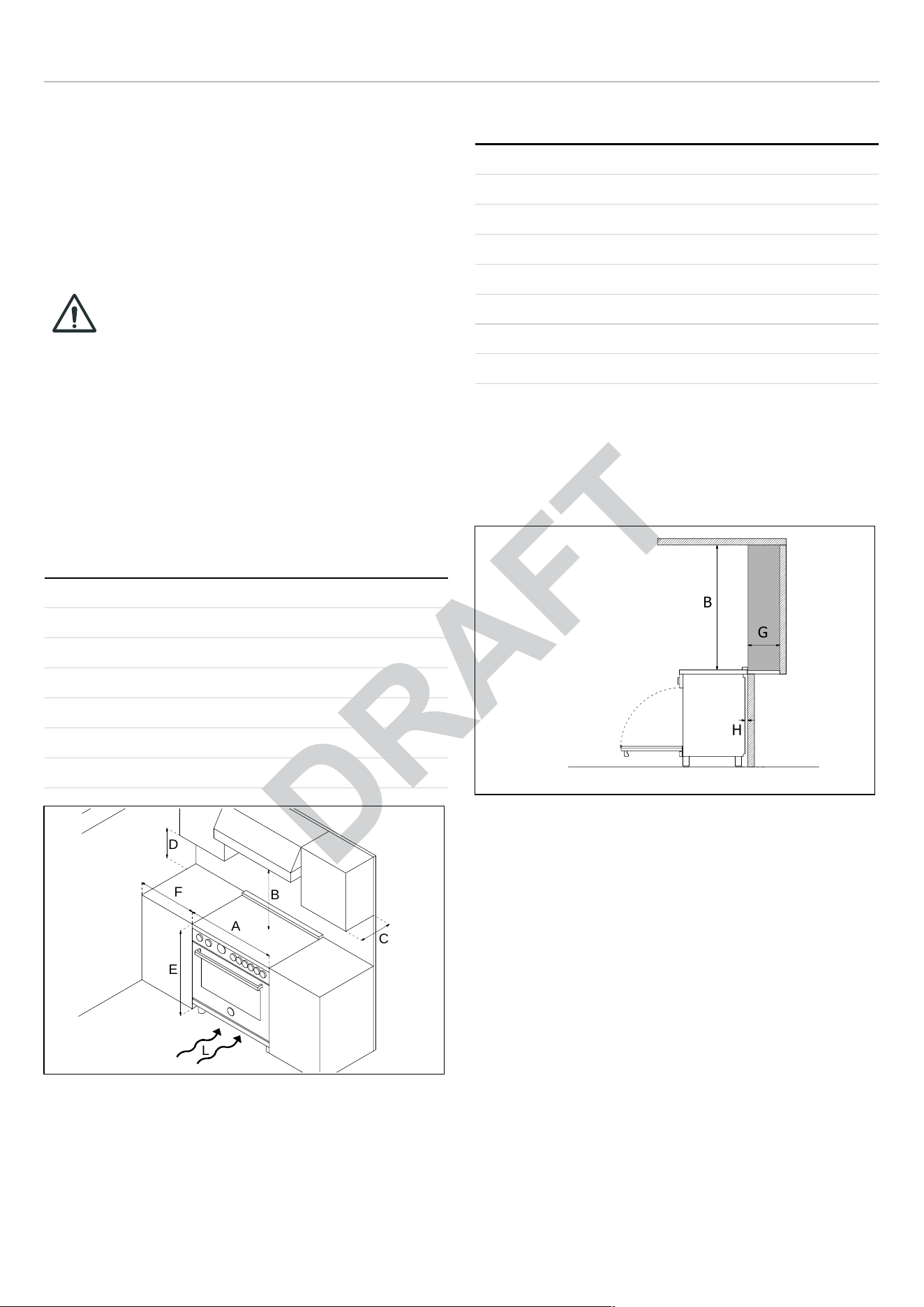
Fig. 3
If installing toekick, verify that the sum of the cut out areas
equal the recommended ventilation (L)
48″ area 51 ½ sq. inches (33107 mm
2
).
METAL HOOD
A
48″(122 cm)
B
25 1/2″(65 cm) and 31 1/2″ (80 cm)
C 13″ (33.0 cm)
D
18″ (45.7 cm)
E
35″ 1/2 (90.2 cm) / 37″ 1/4 (94.6 cm)
F
6″ (15.2 cm)
G 6″ (15.2 cm)
H
1″ 9/16 (4 cm)
When installed in combination with a hood manufactured in
a metal material or metal surface finish, refer to the hood
manufacturer’s requirements for installation. In the event
the hood manufacturer does not make any specific
indication as to installation distances, consider the
distance B.
Fig. 4
Shaded area behind range indicates minimum clearance to
combustible surfaces, combustible materials cannot be
located within this area. 12″ (305 mm) min. to combustible
surface with Flush Island Trim.
For Flush Island installations, counter surface should have
a cantilever edge meeting the back section of the Flush
Island Trim accessory. As defined in the “National Fuel Gas
Code” (ANSI Z223.1, Current Edition).
Clearances from non-combustible materials are not part of
the ANSI Z21.1 scope and are not certified by CSA.
Clearances of less than 6″ (15,2 cm) must be approved by
the local codes and/or by the local authority having
jurisdiction.
A
F
D
B
C
E
L
B
G
H
14
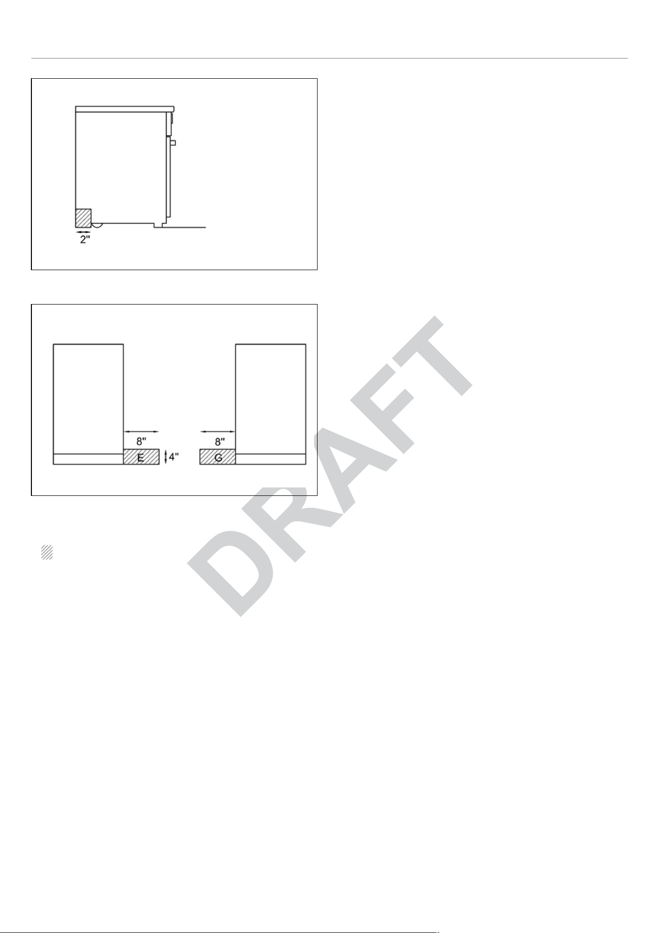
INSTALLATION REQUIREMENTS
Fig. 5
Fig. 6
installation area for the connection
ELECTRICAL
A properly-grounded horizontally- mounted electrical
receptacle should be installed no higher than 3″ (7.6 cm)
above the floor, no less than 2″ (5 cm) and no more than 8″
(20.3 cm) from the left side (facing product).
Check all local code requirements.
GAS
An agency-approved, properly-sized manual shut-off valve
should be installed no higher than 3″ (7.6 cm) above the
floor and no less than 2″ (5 cm) and no more than 8″ (20.3
cm) from the right side (facing product).
To connect gas between shut-off valve and regulator, use
agency-approved, properly sized flexible or rigid pipe.
Check all local code requirements.
15
ELECTRICAL CONNECTION
WARNING
ELECTRICAL SHOCK HAZARD
Disconnect electrical power at the circuit
breaker box or fuse box before installing
the appliance.
Provide appropriate ground for the
appliance.
Use copper conductors only.
Failure to follow these instructions could
result in serious injury or death.
This unit is manufactured for a polarized, grounded 120
volt/60 Hz, 16 amp system.
Electric power consumption is about 300 W for 30″ and 36″,
1200W for 48″.
The minimum of 102 VAC is required for proper operation
of gas ignition systems.
The circuit must be grounded and properly polarized.
The unit is equipped with a SJT power cord and a NEMA 5-
15P plug. In case of replacement, the power cord shall be
replaced with one of the same type, size and length.
WARNING
Electrical grounding
This appliance is equipped with a four-
prong plug for your protection against
shock hazard and should be plugged
directly into a properly grounded socket. Do
not cut or remove the grounding prong from
this plug.
CAUTION
Label all wires prior to disconnecting when
servicing controls. Wiring errors can cause
improper and dangerous operation.
Verify proper operation after servicing.
The appliance shall be connected to a single phase electric
line rated at 120/208Vac or 120/240Vac and 60Hz
frequency.
Install a suitable electric power supply receptacle
connection type NEMA 14-50R able to support a load of at
least an ampacity as per indication in following table.
Install a suitable electric power supply receptacle
connection type NEMA 14-50R able to support a load of at
least 30 A (per line) according to local code requirements.
For four or three wires power supply connection system
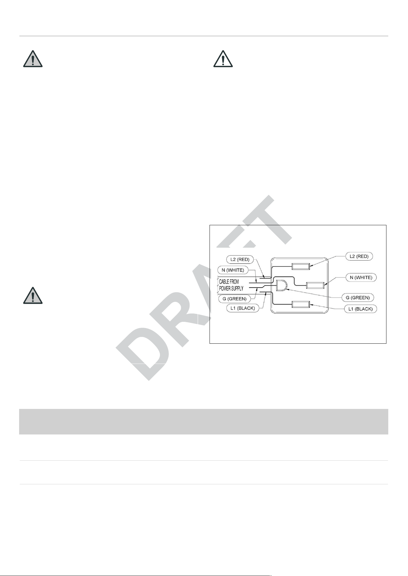
see diagram below.
Fig. 7 FOUR-WIRE CONN.RECEPTACLE NEMA 14-50R
Check your local code for which of the options below
should be used in grounding the receptacle power supply
connections.
ELECTRICAL CONNECTION TABLE
TYPE
VOLTAGE CIRCUIT RATING ELECTRICAL
SUPPLY
FMC SIZE CONNECTORS
WIRES SIZE
L1 (black)
L2 (red)
N
(white)
G
(green)
48 DFM 120/208V 5400W 30A 40A
1″ 12 10
120/240V
6700W 37A 40A
16
ELECTRICAL CONNECTION
FOUR WIRES CONNECTION
• Connect the L1 receptacle terminal to the incoming
BLACK electrical supply wire (L1-hot wire)
• Connect the L2 receptacle terminal to the incoming RED
electrical supply wire (L2-hot wire)
• Connect the NEUTRAL receptacle terminal to the
incoming NEUTRAL (WHITE) electrical supply wire
• Connect the GROUND receptacle terminal to the
incoming GROUND (GREEN) electrical supply wire.
DO NOT USE EXTENSION CORDS WITH THIS
APPLIANCE AS IT MAY RESULT IN FIRE, ELECTRIC
SHOCK OR OTHER type of PERSONAL INJURY.
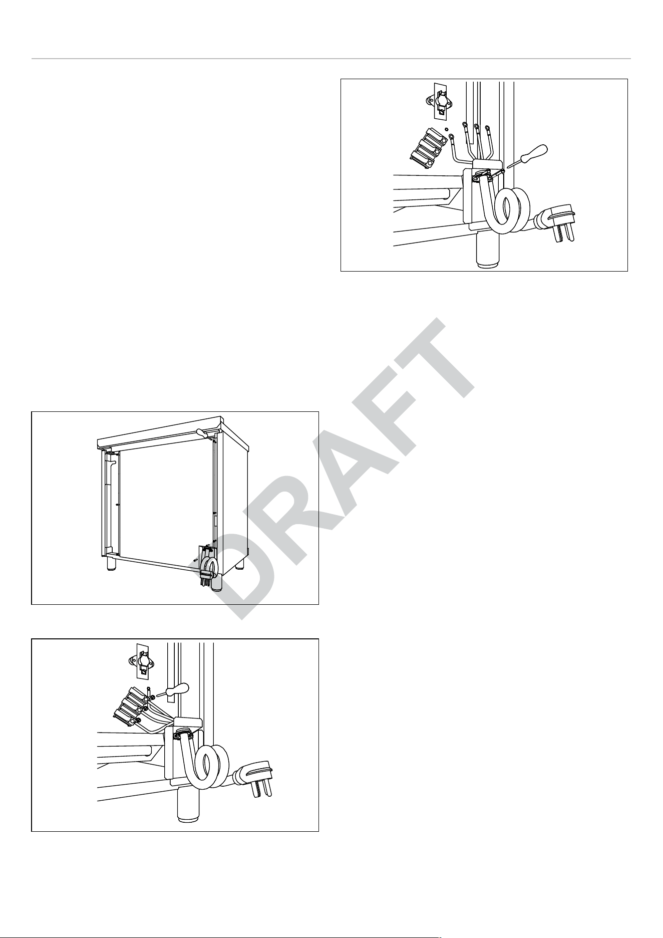
The appliance is equipped at the factory with an electric
supply cord set 4 wires type with ring terminals (L1, L2, N,
Ground) suitable for range use UL/CSA listed type
SRDT/DRT 2x6AWG (L1, L2)+2x8AWG (N, G) rated 300V,
40 or 50A with fused plug type NEMA 14-50P; cable length
1.5 m.; in case the supply cord set must be replaced, it
shall be replaced with an identical set having the same
technical specs and following carefully the instructions and
diagrams below:
Fig. 8
Fig. 9
Fig. 10
17
ELECTRICAL CONNECTION
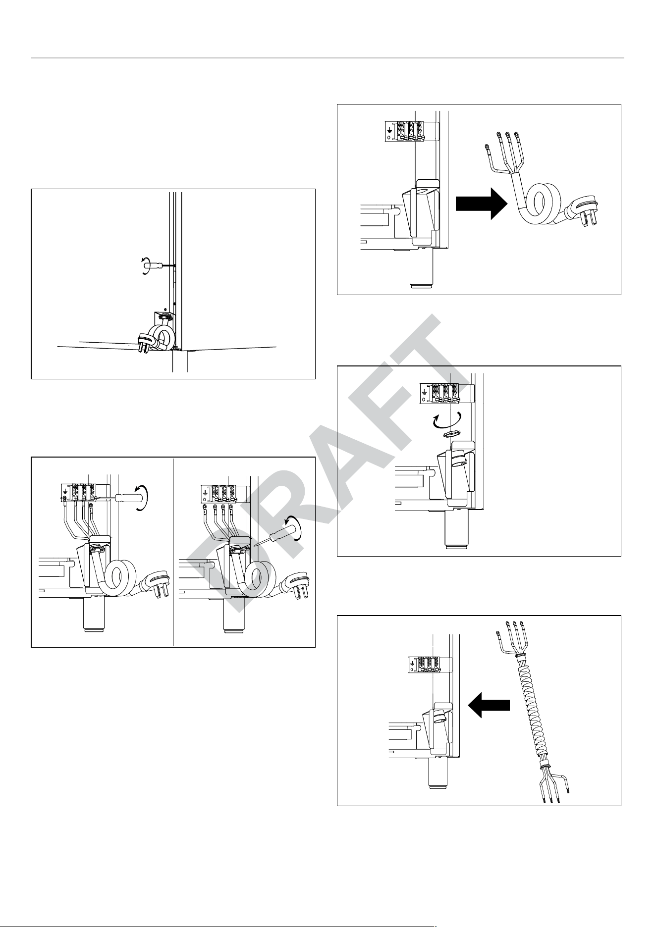
METAL CONDUIT CONNECTION - OPTION
In case the supply cord set must be replaced with a metal
conduit, follow the technical specs as in ELECTRICAL
CONNECTION TABLE. The instructions and diagrams
below:
1) Remove the back panel
Fig. 11
2) Unscrew the single wire connectors
3) Unscrew the cable fastener
Fig. 12
4) Remove the power cord
Fig. 13
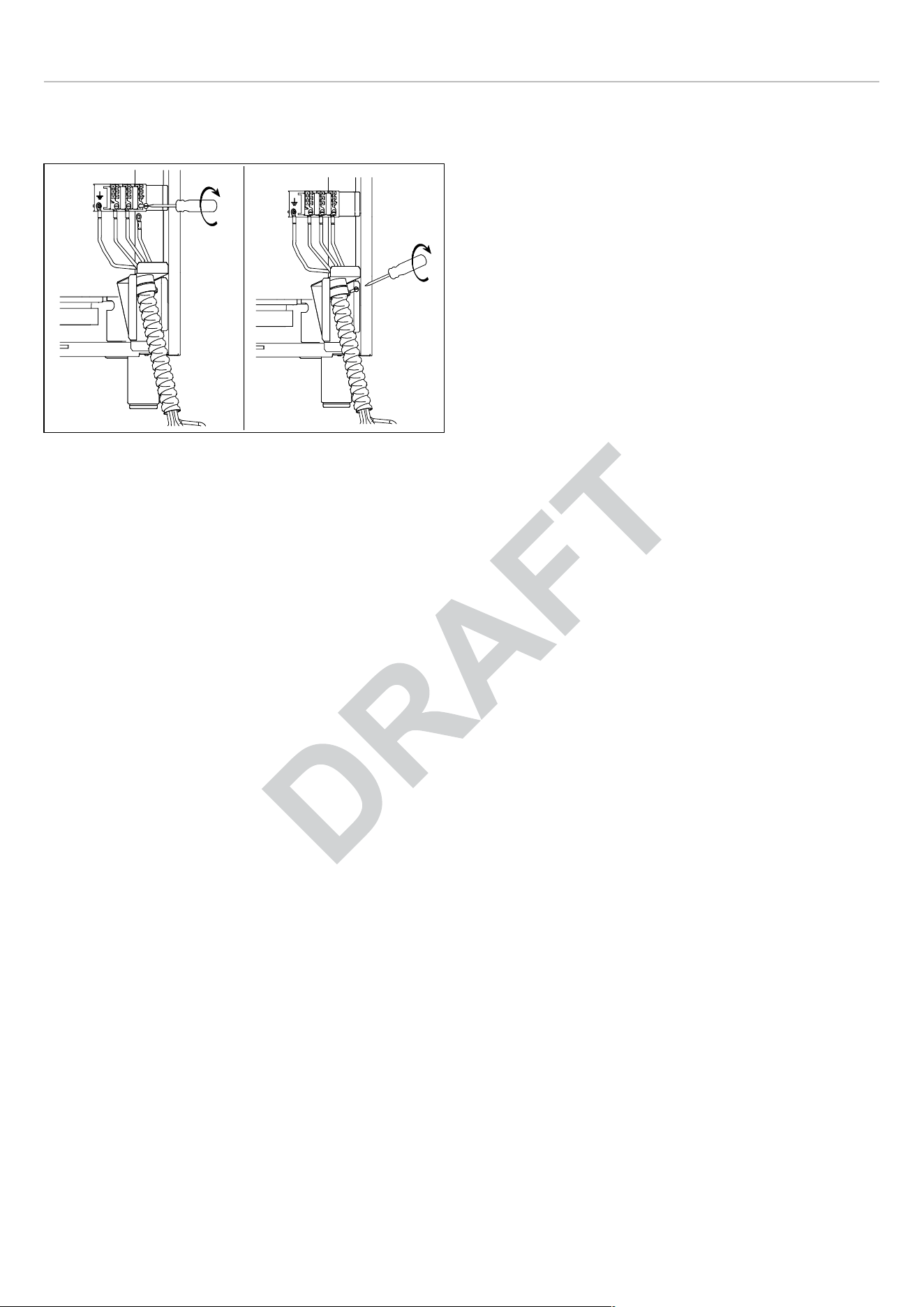
5) Using the fixing nut, position the cable fastener on the
support bracket.
Fig. 14
6) Insert the Flexible metal conduit into the cable fastener
Fig. 15
7) Screw in the single wire connectors to the terminal block
18
GAS CONNECTION
WARNING
DO NOT USE AN OPEN FLAME WHEN
CHECKING FOR LEAKS!
Leak testing of the appliance shall be conducted according
to the manufacturer’s instructions. Before placing the oven
into operation, always check for leaks with soapy water
solution or other acceptable method.
Check for gas leakage with soapy water solution or other
acceptable methods in all gas connections installed
between inlet gas pipe of the appliance, gas regulator, till to
the manual shut-off valve.
All gas connections must comply with national and local
codes. The gas supply line (service) must be the same size
or greater than the inlet line of the appliance. This range
uses a 1/2″ NPT inlet (see drawing below for details of gas
connection). On all pipe joints use appropriate sealant
resistant to gas to joint the adapter to range manifold use
only the blue gasket supplied.
If necessary, the appliance must be converted by the dealer,
by a factory-trained professional or by a qualified licensed
plumber or gas service company.
Gas conversion is important for safe and effective use of
the appliance. It is the responsibility of the dealer and the
owner of the range to perform the appropriate gas
conversion following the directions of the manufacturer.
THE GAS CONVERSION PROCEDURE IS DESCRIBED
IN THIS MANUAL AND IN THE PACKAGE CONTAINING
THE CONVERSION NOZZLES SHIPPED WITH EVERY
RANGE.
Please provide the service person with this manual before
work is started on the range.
MANUAL SHUT-OFF VALVE
THIS VALVE IS NOT SHIPPED WITH THE APPLIANCE
AND MUST BE SUPPLIED BY THE INSTALLER.
The manual shut-off valve must be installed in the gas
service line between the gas hook-up on the wall and the
appliance inlet, in a position where it can be reached
quickly in the event of an emergency.
In Massachusetts:
A ‘T’ handle type manual gas valve must be installed in the
gas supply line to this appliance.
FLEXIBLE CONNECTIONS
In case of installation with flexible couplings and/ or quick-
disconnect fittings, the installer must use a heavy-duty,
AGA design-certified commercial flexible connector of at
least 1/2″ (1.3 cm) ID NPT (with suitable strain reliefs) in
compliance with ANSI Z21.41 and Z21.69 standards.
In Massachusetts:
The unit must be installed with a 36″ (3-foot) long flexible
gas connector.
In Canada:
Use CAN 1-6.10-88 metal connectors for gas appliances
and CAN 1-6.9 M79 quick disconnect device for use with
gas fuel.
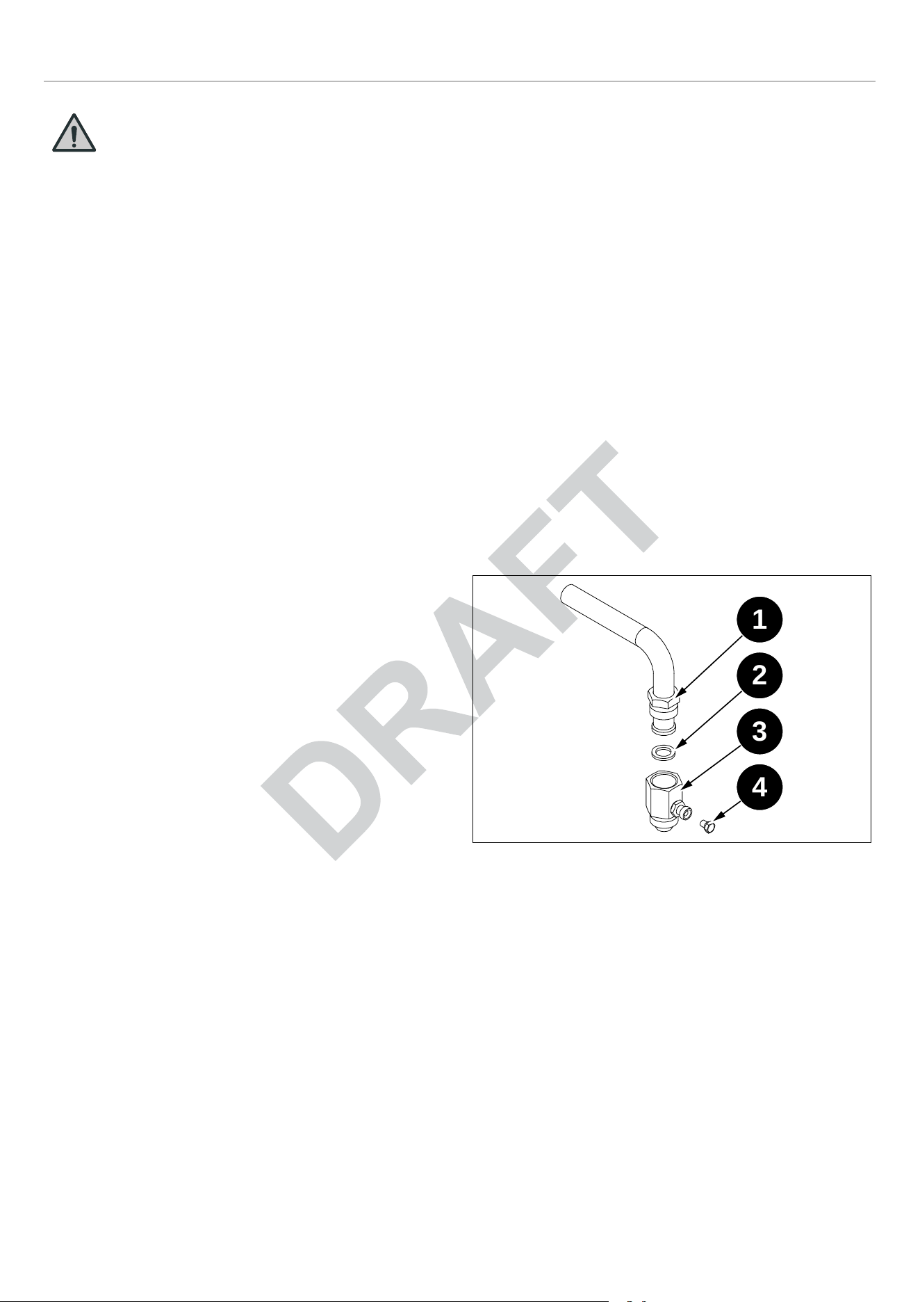
PRESSURE TEST-POINT STOPPER VALVE
To avoid gas leaks, the pressure test-point stopper valve
and gasket supplied with the range must be installed on the
gas fitting at the back of the range according to the diagram
below.
Fig. 19
1) Gas Pipe
2) Gasket
3) Gas connection adaptor 1/2″ npt with pressure test point
1/8″ npt (to be fixed toward external side of the
appliance)
4) Pressure test-point
1
2
3
4
22
GAS CONNECTION
PRESSURE REGULATOR
Since service pressure may fluctuate with local demand,
every gas cooking appliance must be equipped with a
pressure regulator on the incoming service line for safe and
efficient operation.
The pressure regulator shipped with the appliance has two
female threads 1/2″ NPT. The regulator shall be installed
properly in order to be accessible when the appliance is
installed in its final position.
Manifold pressure should be checked with a manometer
and comply with the values indicated below:
Natural gas 4.0″ iwc
LP/Propane 10.0″ iwc.
Incoming line pressure upstream from the regulator must
be 1″ iwc higher than the manifold pressure in order to
check the regulator.
The regulator used on this range can withstand a maximum
input pressure of 1/2 PSI (13.8″ iwc or 3.5 kPa). If the line
pressure exceeds that amount, a stepdown regulator is
required.
The appliance, its individual shut-off valve, and the
pressure regulator must be disconnected from the gas line
during any pressure testing of that system at pressures in
excess of 1/2 PSI (13.8″ iwc or 3.5 kPa).
The individual manual shut-off valve must be in the OFF
position during any pressure testing of the gas supply
piping system at test pressures equal to or less than 1/2
PSI (13.8″ iwc or 3.5 kPa).
WARNING
Before carrying out any servicing operation
disconnect the appliance from gas and
electric supply and extra appliance from
final installation place in order to have
access to the appliance for proper servicing
intervention.
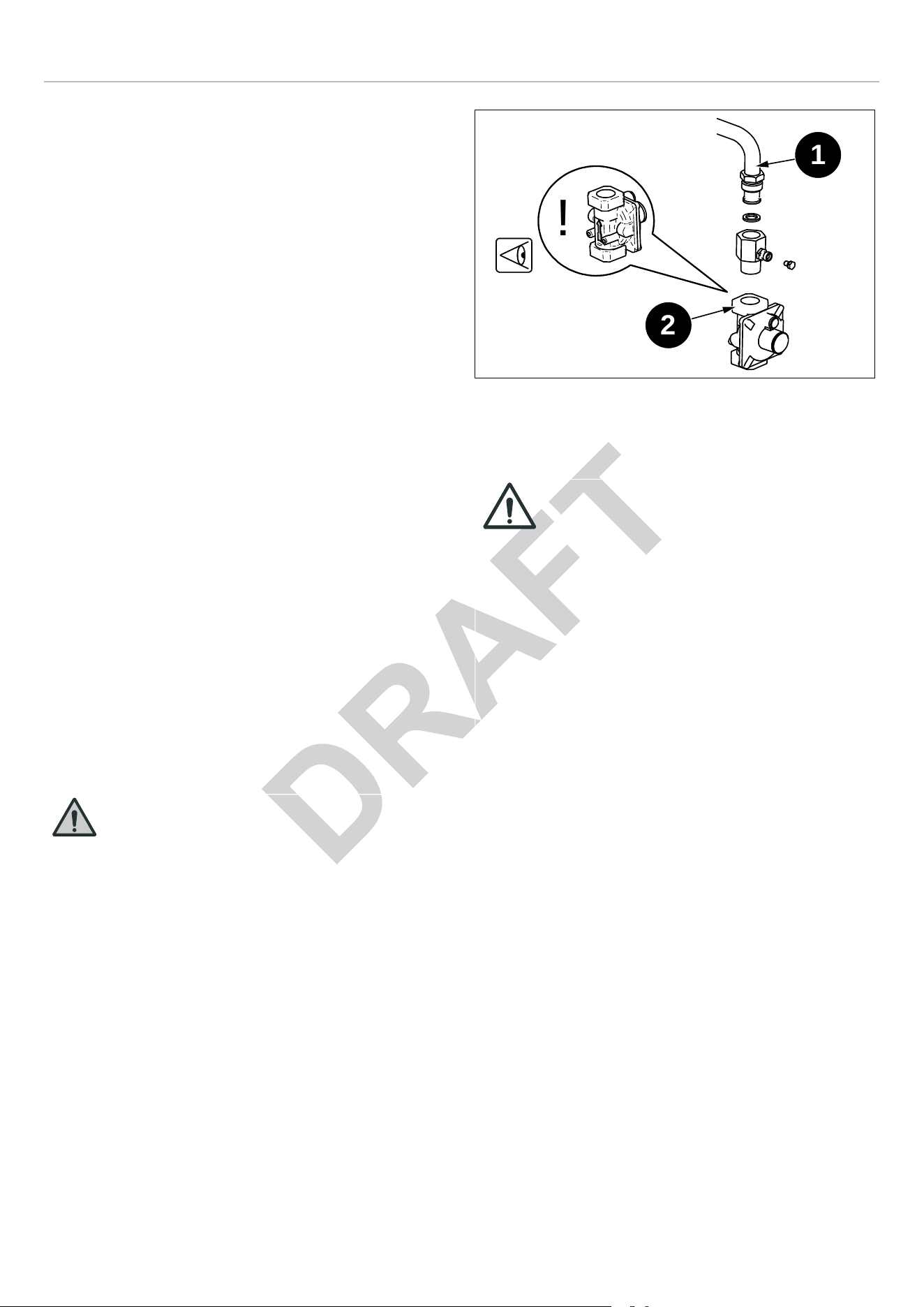
Fig. 20
1) Range cooker gas pipe gas entry
2) Pressure regulator
IMPORTANT
• PRESSURE REGULATOR MUST BE
MOUNTED WITH THE ARROW
POINTING IN THE DIRECTION OF
GAS FLOW!
• INCORRECT MOUNTING MAY CAUSE
PERFORMANCE ISSUES AND MAY
CONSTITUTE A GAS HAZARD.
• ISSUES DERIVED FROM INCORRECT
INSTALLATION OF PRESSURE
REGULATOR ARE NOT COVERED
UNDER MANUFACTURER
WARRANTY.
!
1
2
23
INSTALLATION
APPLIANCE INSTALLATION
UNPACKING THE RANGE
• Remove all packing materials from the shipping pallet
but leave the adhesive-backed foam layer over brushed-
metal surfaces to protect it from scratches until the
range is installed in its final position. Only the film on the
side panels should be removed before inserting the
range between the cabinets.
• Examine the appliance after unpacking it. In the event of
transport damage, do not plug it. Take pictures of the
damage and report it immediately to the freight forwarder.
• Remove the oven door(s). This will reduce the weight of
the range.
• The grates, griddle plate, burner caps, and oven racks
should be removed to facilitate handling.
• Before moving the range, protect the floor to prevent
damage.
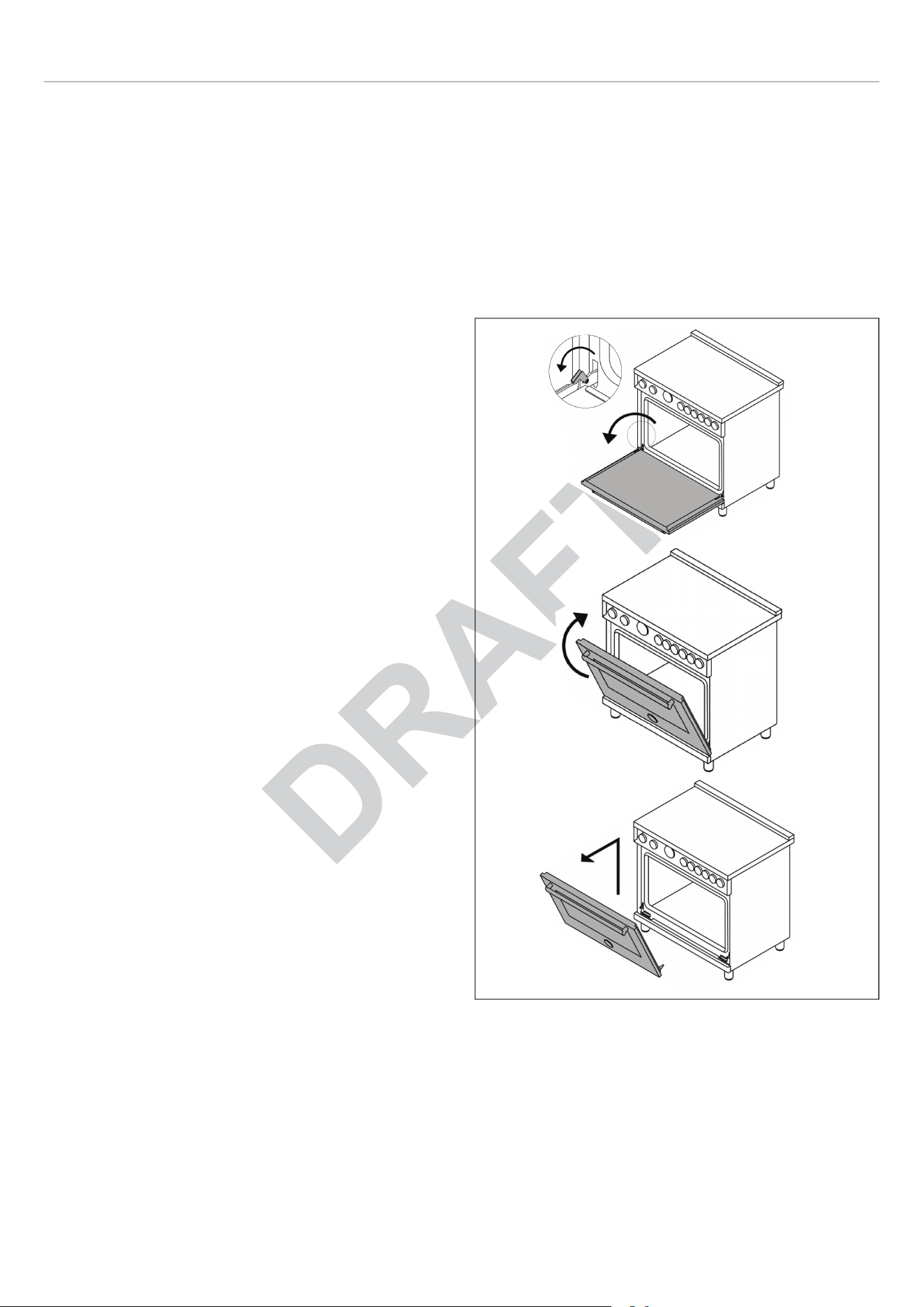
REMOVING THE OVEN DOOR
Prepare the door for removal. Flip up the locking clamps on
each door hinge. Slowly shut the door until the protruding
clamps stop the movement.
Pull oven door upwards and remove.
Do not lift or carry the oven door by its handle!
This may damage the hinges.
Fig. 21
24
INSTALLATION
INSTALLING THE LEGS
Bertazzoni ranges must be used only with the legs properly
installed.
Four height-adjustable legs are supplied with the range in
the polystyrene container situated over the appliance.
Before installing the legs, position the appliance near its
final location as the legs are not suitable for moving the
appliance over long distances. After unpacking the range,
raise it enough to insert the legs in the appropriate
receptacles situated on the lower part of the appliance.
Lower the range gently to keep any undue strain from legs
and mounting hardware. If possible use a pallet or lift jack
instead of tilting the unit.
Adjust leg height to the desired level by twisting the inside
portion of the leg assembly until the proper height is
reached. Check with a level that the cooktop is perfectly
level.
Fig. 22
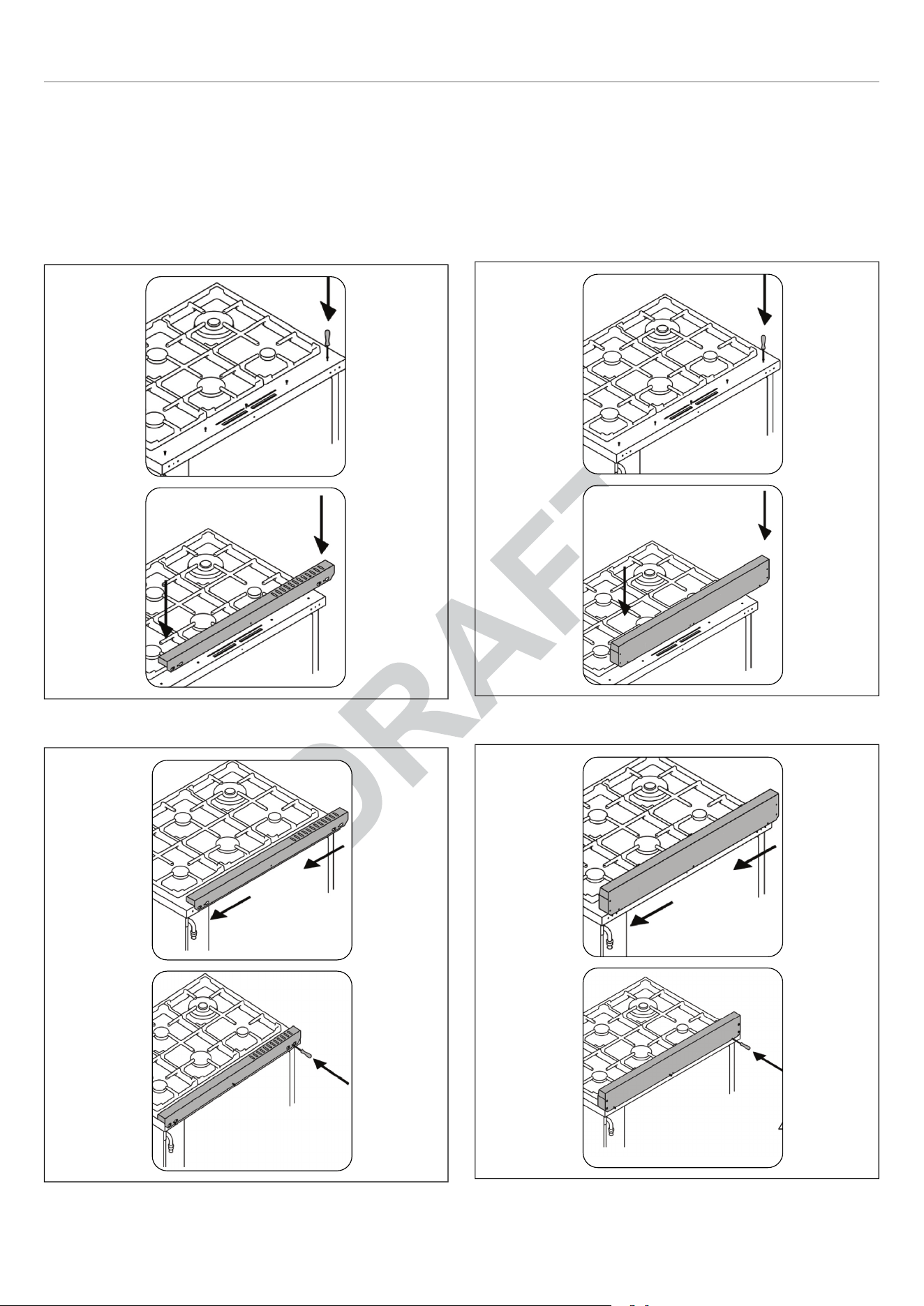
INSTALLING THE WORKTOP FRONTGUARD
To increase the clearance between the front edge of the
worktop and the burners, it is possible to install a front
guard for the worktop.
• To install the front guard, locate the two fixing holes on
the end of the front guard.
• Locate the two fixing holes on the bottom facet of the
worktop.
• Fix the front guard with its two screws.
Fig. 23
1 2
3
5
4
25
INSTALLATION
INSTALLING THE ISLAND TRIM
The island trim must be installed prior to operation of the
appliance for appropriate ventilation of the oven
compartment.
The island trim is only placed on the cooktop, remove all
tape and packaging before installing it.
Fig. 24
Fig. 25
INSTALLING BACKGUARD (OPTIONAL)
The backguard must be installed prior to operation of the
appliance for appropriate ventilation of the oven
compartment.
The backguard is an optional contact you dealer for buying
it.
Fig. 26
Fig. 27
26
INSTALLING THE ANTI-TIP DEVICES
ANTI-TIP BRACKETS
The anti-tip bracket shipped with the range must be
properly secured to the rear wall as shown in the picture
below.
The height of the bracket from the floor must be determined
after the range legs have been adjusted to the desired
height and after the range has been levelled.
• Measure the distance from the floor to the bottom of the
anti-tip bracket receptacle on the back of the appliance.
• Position the anti-tip brackets on the wall at the desired
height plus 1/8″ (0.32 cm). The brackets must be placed
at 2″5/16 (6.0 cm) from the side of the range.
• Secure the brackets to the wall with appropriate
hardware.
• Slide the range against the wall until the brackets are
fully inserted into their receptacles on the back of the
range.
Fig. 28
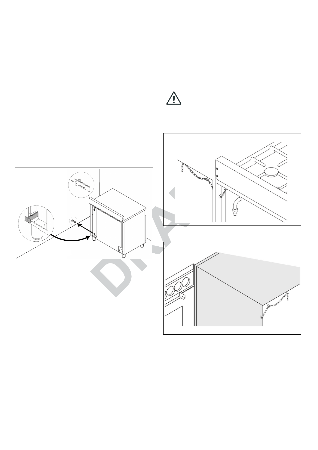
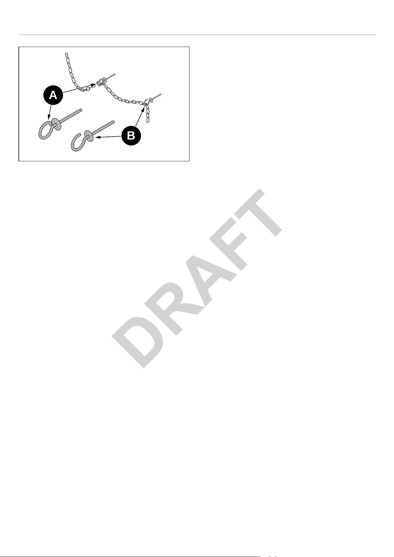
ANTI/TILT CHAIN
The anti-tilt chain shall be installed on right or left side
alternatively according below instructions. The chain shall
be hand pulled and fixed to open hook through closed ring.
Disengage the chain prior to moving the appliance for
service.
CAUTION
Once servicing operation have been
completed the anti-tilt devices (brackets
and chain) shall be re-engaged according
above instruction/installations.
Fig. 29
Fig. 30
27
GAS CONVERSION
WARNING
Before carrying out this operation,
disconnect the appliance from gas and
electricity.
Gas conversion shall be conducted by a
factory-trained professional.
Call the customer service hotline to identify
a factory-trained professional near your
home.
The gas conversion procedure for this range includes 6
steps:
1) Pressure regulator
2) Surface burners
3) Oven burner
4) Broiler burner
5) Visual checks prior to closure of oven bottom panel
6) Adjustment of minimum setting.
The conversion is not completed if all 6 steps have not
been concluded properly.
Before performing the gas conversion, locate the package
containing the replacement nozzle shipped with every
range.
IMPORTANT
Each nozzle has a number indicating its
flow diameter printed on the body. Consult
the table number 1 for matching nozzles to
burners.
Save the nozzles removed from the range
for future use.
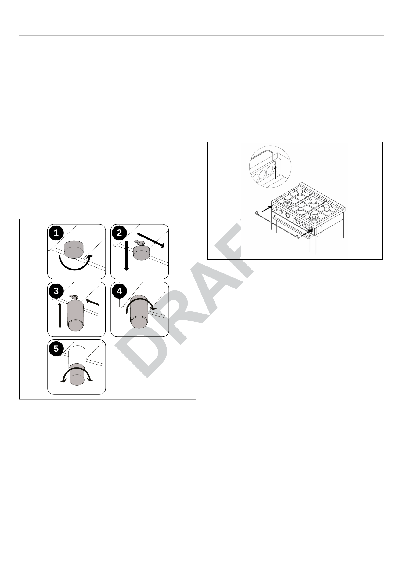
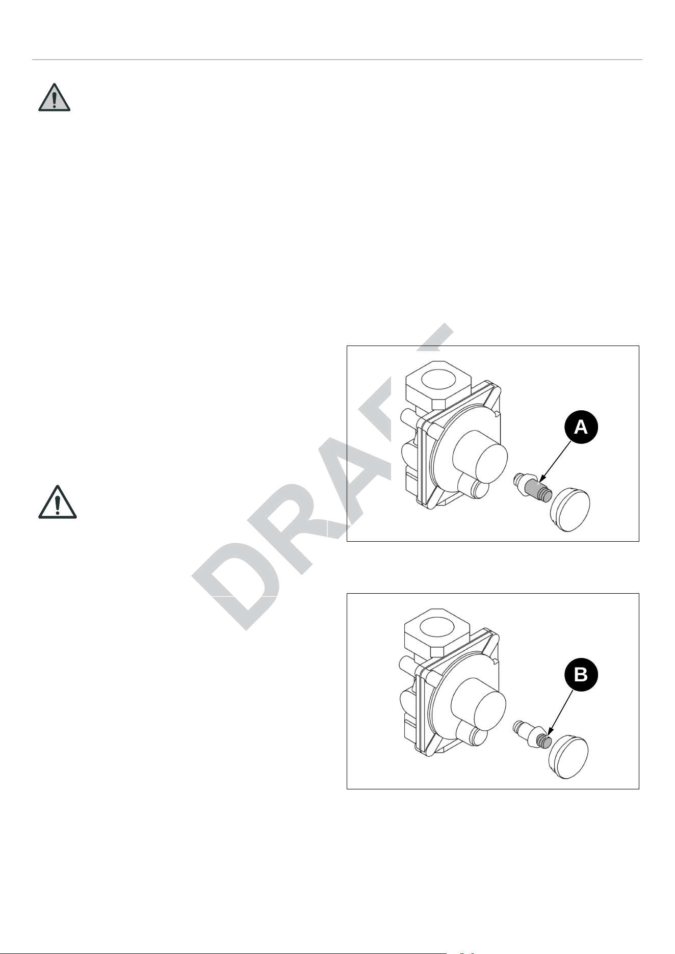
STEP 1: PRESSURE REGULATOR
The pressure regulator supplied with the appliance is a
convertible type pressure regulator for use with Natural
Gas at a nominal outlet pressure of 4″ iwc or LP gas at a
nominal outlet pressure of 10″ iwc and it is pre-arranged
from the factory to operate with one of these gas/pressure
as indicated in the labels affixed on the appliance, package
and Instruction booklet.
To convert the regulator for use with the other gas:
Unscrew by hand the upper cap of the regulator, remove
the white plastic attachment from the cap, reverse its
direction and screw it again firmly against the cap. The
white plastic attachment has arrows indicating the position
for natural gas (NAT) and LP gas (LP).
Screw by hand the metal cap in the original position on the
regulator.
Fig. 32
• A LP
Fig. 33
• B NAT
A
B
29
GAS CONVERSION
STEP 2: SURFACE BURNERS
To replace the nozzles of the surface burners, lift up the
burners and unscrew the nozzles shipped with the range
using a 7 mm (socket wrench).
Replace nozzles using the conversion set supplied with the
range or by a Bertazzoni authorized parts warehouse. Each
nozzle has a number indicating its flow diameter printed on
the body.
Consult the table number 1 and matching nozzles to
burners.
Fig. 34
Fig. 35
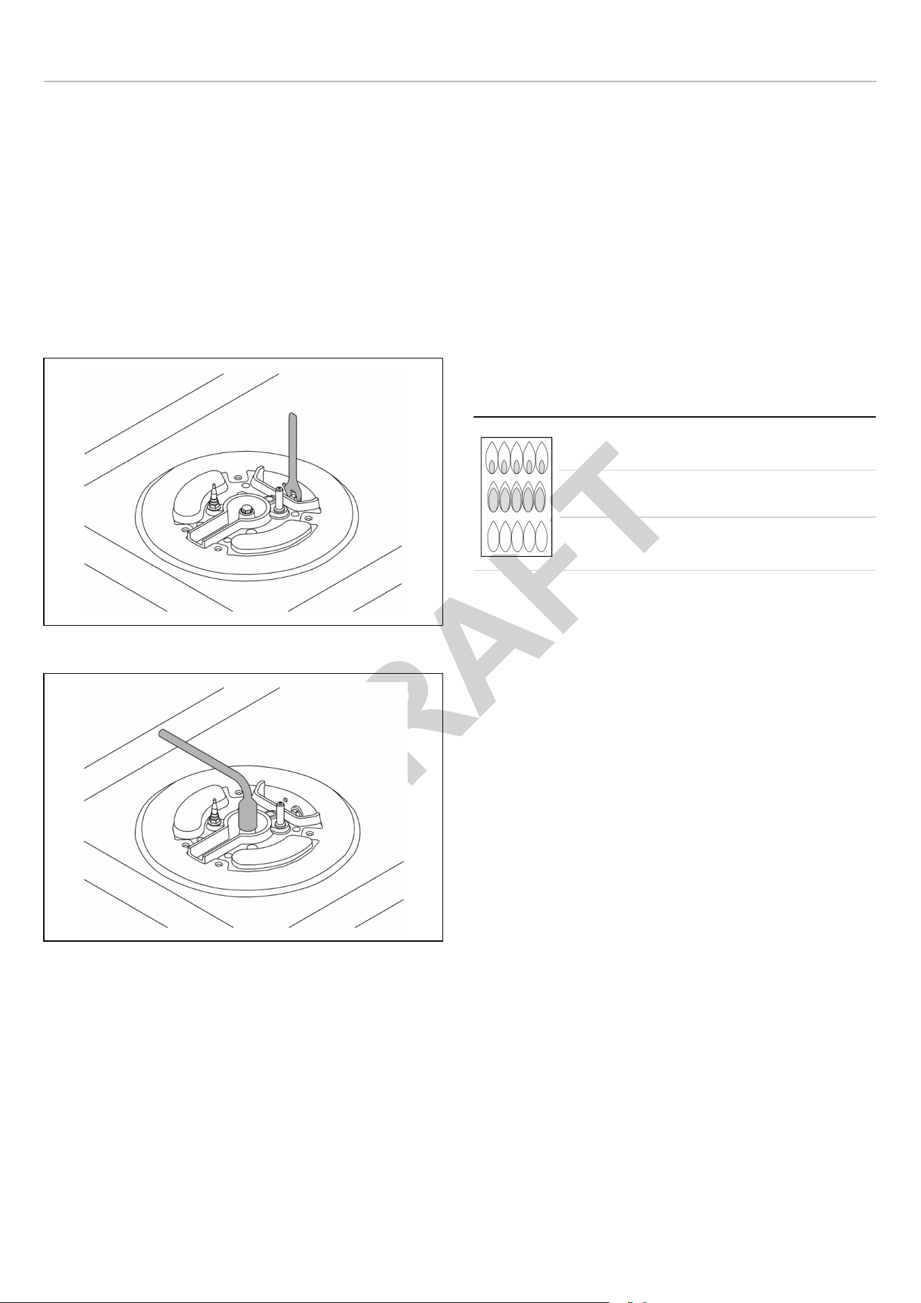
STEP 3: VISUAL CHECKS
SURFACE BURNERS
The burner flame color should be blue with no yellow on the
tips. It is not uncommon to see orange in the flame color;
this indicates the burning of airborne impurities in the gas
and will disappear with use. With propane (LP) gas, slight
yellow tips on the primary icon are normal.
The flame should burn completely around the burner cap. If
it does not, check that the cap is positioned correctly on the
base and that the ports are not blocked.
The flame should be stable with no excessive noise or
fluttering.
yellow flames: further adjustment is required
yellow tips on outer cones: normal for LP
gas
soft blue flames: normal for natural gas
After performing all these visual checks, reinstall the
bottom panel of the oven compartment and proceed to
setting the minimum for each burner.
30
GAS CONVERSION
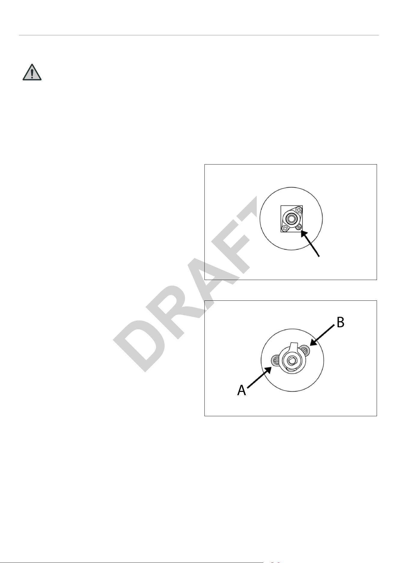
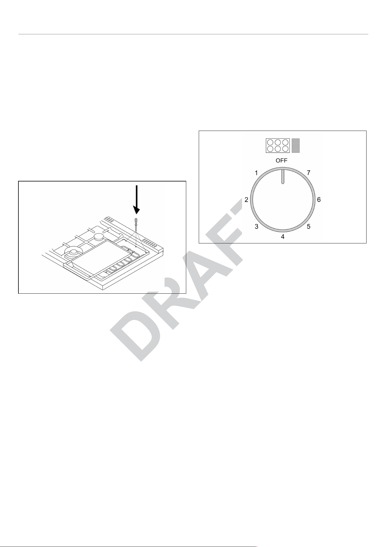
STEP 4: MINIMUM FLAME ADJUSTMENT
WARNING
These adjustments should be made only
for use of the appliance with natural gas.
For use with liquid propane gas, the choke
screw must be fully turned in a clockwise
direction.
SURFACE BURNERS
Light one burner at a time and set the knob to the
MINIMUM position (small flame).
Remove the knob.
The range is equipped with a safety valve. Using a small-
size slotted screwdriver, locate the choke valve on the
valve body and turn the choke screw to the right or left until
the burner flame is adjusted to desired minimum.
Make sure that the flame does not go out when switching
quickly from the MAXIMUM to the MINIMUM position.
Fig. 36
Fig. 37
For the gas valve of dual burner the choke valve is located
on the valve body (Fig. 37 ), the A screw adjust the outer
ring, the B screw adjust the inner ring.
A
B
31

INSTALLATION CHECKLIST
A qualified installer should carry out the following checks:
Range mounted on its legs
Island trim or Backguard attached according to
instruction
Anti-tip device properly installed
Clearance to cabinet surfaces as manufacturer’s
guideline
Proper ground connection
Gas service line connected following
manufacturer’s guideline
Valves, stoppers and gasket installed between the
range and the service line
Gas connection tested and free of gas leaks
Range settled for the type of gas available in the
household
Each burner lights satisfactorily, both individually
and with other burners operating
Flame appear sharp blue, with no yellow tipping,
shooting or flame lifting
Minimum settled for all burners
Oven and broiler lights satisfactorily and works
properly
Oven light works properly.
32

FINAL PREPARATION
• Before using the appliance, remove any protective wrap
from the stainless steel.
• All stainless steel body parts should be wiped with hot,
soapy water and with a liquid stainless steel cleanser.
• If buildup occurs, do not use steel wool, abrasive cloths,
cleaners, or powders!
• If it is necessary to scrape stainless steel to remove
encrusted materials, soak with hot, wet cloths to loosen
the material, then use a wood or nylon scraper.
• Do not use a metal knife, spatula, or any other metal tool
to scrape stainless steel! Scratches are almost
impossible to remove.
• Before using the oven for food preparation, wash the
cavity thoroughly with a warm soap and water solution to
remove film residues and any dust or debris from
installation, then rinse and wiped dry.
CAUTION
When using the oven for the first time it
should be operated for 15-30 minutes at a
temperature of about 500℉/260℃ (main
oven) or 440℉/227℃ (auxiliary oven)
without cooking anything inside in order to
eliminate any moisture and odors from the
internal insulation.
33

BERTAZZONI SERVICE
Bertazzoni is committed to providing the best customer and
product service. We have a dedicated team of trained
professionals to answer your needs.
If you own a Bertazzoni appliance and need service in the
US or Canada please use the following contact information:
If located in the USA:
866 905 0010
https://us.bertazzoni.com/more/support
If located in CANADA:
800 561 7265
https://ca.bertazzoni.com/more/support
Make sure to keep the following information on hand. Our
customer service team will require it to open a service ticket
or troubleshoot.
• Purchase Date
• Model*
• Serial Number /Production Date*
• *Can be found on data plate
34

WARNINGS
Warning and Important Safety Instructions appearing in this
manual are not meant to cover all possible conditions and
situations that may occur.
Common sense, caution, and care must be exercised when
installing, maintaining, or operating the appliance.
Read and follow all instructions before using this
appliance to prevent the potential risk of fire, electric
shock, personal injury or damage to the appliance as a
result of improper usage of the appliance. Use
appliance only for its intended purpose as described in
this manual.
Save this Manual for local electrical inspector’s use. Read
and save these instructions for future reference. Observe
all governing codes, ordinances and regulations.
WARNING
If the information in these instructions is not
followed exactly, a fire or explosion may
result causing property damage, personal
injury or death.
• Do not store or use gasoline or other
flammable vapors and liquid in the
vicinity of this or any other appliance.
• WHAT TO DO IF YOU SMELL GAS
• Do not try to light any appliance.
• Do not touch any electrical switch.
• Do not use any phone in your building.
• Immediately call your gas supplier
from a neighbor’s phone. Follow the
gas supplier’s instructions.
• If you cannot reach your gas
suppliers, call the fire department.
• Installation and service must be
performed by a qualified installer,
service agency or the gas supplier.
In Massachusetts:
All gas products must be installed by a “Massachusetts”
licensed plumber or gasfitter. A “T” handle type manual gas
valve must be installed in the gas line connected to this
appliance.
To ensure proper and safe operation: Appliance must be
properly installed and grounded by a qualified technician.
DO NOT attempt to adjust, repair, service, or replace any
part of your appliance unless it is specifically recommended
in this manual. All other servicing should be referred to a
qualified servicer. Have the installer show you the location
of the gas shut-off valve and how to shut it off in an
emergency.
A certified technician is required for any adjustments or
conversions to Natural or LP gas.
TO PREVENT FIRE OR SMOKE DAMAGE
• Be sure all packing materials are removed from the
appliance before operating it.
• Never let clothing, potholders, or other flammable
materials come in contact with or too close to any
element, top burner or burner grate until it has cooled.
• If appliance is installed near a window, proper
precautions should be taken to prevent curtains from
blowing over burners.
• Never leave any items on the cooktop. The hot air from
the vent may ignite flammable items and may increase
pressure in closed containers which may cause them to
burst.
• Many aerosol-type spray cans are EXPLOSIVE when
exposed to heat and may be highly flammable. Avoid
their use or storage near an appliance.
IN CASE OF FIRE
Turn off appliance and ventilation hood to avoid spreading
the flame. Extinguish flame then turn on hood to remove
smoke and odor.
• Cooktop: Smother fire or flame in a pan with a lid or
cookie sheet.
• NEVER pick up or move a flaming pan.
• Oven: Smother fire or flame by closing the oven door.
DO NOT use water on grease fires. Use baking soda, a
dry chemical or foamtype extinguisher to smother fire or
flame, if available, a multipurpose dry chemical or foam
type extinguisher.
CHILD SAFETY
• NEVER leave children alone or unsupervised near the
appliance when it is in use or is still hot.
• NEVER allow children to sit or stand on any part of the
appliance as they could be injured or burned.
•
CAUTION
Do not store items of interest to children
in cabinets above the range or on the
backguard of the range. Children
climbing on the range to reach those
items could be seriously injured.
35

WARNINGS
COOKING SAFETY
• Once the unit has been installed as outlined in the
Installation Instructions, it is important that the fresh air
supply is not obstructed. The use of a gas cooking
appliance results in the production of heat and moisture
in the room in which it is installed.
• Ensure that the kitchen is well-ventilated. Keep natural
venting holes open or install a mechanical ventilation
device. Prolonged or intensive use of the appliance may
call for additional (such as opening a window) or more
effective ventilation (such as increasing the level of a
mechanical ventilation if present).
• NEVER use aluminum foil to cover oven racks or oven
bottom. This could result in risk of electric shock, fire, or
damage to the appliance. Use foil only as directed in this
guide.
• To eliminate the hazard of reaching over hot surface
burners, cabinet storage should not be provided directly
above a unit. Temperatures may be unsafe for some
items, such as volatile liquids, cleaners or aerosol
sprays.
• ALWAYS place a pan on a surface burner before turning
it on. Be sure you know which knob controls which
surface burner. Make sure the correct burner is turned
on and that the burner has ignited. When cooking is
completed, turn burner off before removing pan to
prevent exposure to burner flame.
• ALWAYS adjust surface burner flame so that it does not
extend beyond the bottom edge of the pan. An
excessive flame is hazardous, wastes energy and may
damage the appliance, pan or cabinets above the
appliance. This is based on safety considerations.
• NEVER leave a surface cooking operation unattended
especially when using a high heat setting or when deep
fat frying. Boilovers cause smoking and greasy
spillovers may ignite. Clean up greasy spills as soon as
possible. DO NOT use high heat for extended cooking
operations.
• DO NOT heat unopened food containers, build up of
pressure may cause the container to explode and result
in injury.
• ALWAYS let quantities of hot fat used for deep fat frying
cool before attempting to move or handle.
• NEVER wear garments made of flammable material or
loose fitting or long-sleeved apparel while cooking.
Clothing may ignite or catch utensil handles. DO NOT
drape towels or materials on oven door handles. These
items could ignite and cause burns.
• ALWAYS place oven racks in the desired positions while
oven is cool. Slide oven rack out to add or remove food,
using dry, sturdy potholders.
• ALWAYS avoid reaching into the oven to add or remove
food. If a rack must be moved while hot, use a dry pot-
holder.
• ALWAYS turn the oven off at the end of cooking.
• Use care when opening the oven door. Let hot air or
steam escape before moving or replacing food.
• DO NOT cook directly on the oven bottom. This could
result in damage to your appliance. Always use the oven
racks when cooking in the oven.
Do not connect any appliances to the plugs above or near
to the induction cooktop; connection cable insulation can
melt if in contact with heat, and this may result in an injury
and a property damage.
RECOMMENDED UTENSILS
• Use pans with flat bottoms and handles that are easily
grasped and stay cool. Avoid using unstable, warped,
easily tipped or loose-handled pans. Also avoid using
pans, especially small pans, with heavy handles as they
could be unstable and easily tip. Pans that are heavy to
move when filled with food may also be hazardous.
• Be sure utensil is large enough to properly contain food
and avoid boilovers. Pan size is particularly important in
deep fat frying. Be sure pan will accommodate the
volume of food that is to be added as well as the bubble
action of fat.
• To minimize burns, ignition of flammable materials and
spillage due to unintentional contact with the utensil, DO
NOT extend handles over adjacent surface burners.
ALWAYS turn pan handles toward the side or back of the
appliance, not out into the room where they are easily hit
or reached by small children.
• NEVER let a pan boil dry as this could damage the
utensil and the appliance.
• Follow the manufacturer’s directions when using oven
cooking bags.
• Only certain types of glass, glass/ceramic, ceramic or
glazed utensils are suitable for rangetop surface or oven
usage without breaking due to the sudden change in
temperature. Follow manufacturer’s instructions when
using glass.
36

WARNINGS
INDUCTION COOKING SURFACES
• Surface areas on or adjacent to the unit may be hot
enough to cause burns. Do not touch the cooking area
as long as the light indicating residual heat on the glass-
ceramic cooktop area, is “on”; this indicates that the
temperature in the relative area is still high.
• DO NOT COOK ON BROKEN COOKING SURFACE – If
cooking surface should break, cleaning solutions and
spillovers may penetrate the broken cooking surface and
create a risk of electric shock. Contact a qualified
technician immediately.
• Keep a close eye on children because they are unlikely
to see the residual heat warning lights. The cooking
zones are still very hot for some time after use, even if
they are switched off. Make sure that children never
touch them.
• NEVER use aluminum foil to hold the food while cooking
on a glass-ceramic cooktop area.
• Never place pan with bottoms which are not perfectly flat
and smooth on the cooktop area.
• If you drop a heavy pot on your cooktop area it will not
break. On the contrary, if a hard object, such as the salt
shaker or the spice bottle strikes the edge or the corner
of the cooktop area, the cooktop area may break.
• Never use the glass-ceramic cooktop area as support
surface.
• Only use cleaning products made specifically for
ceramic glass cooking surfaces.
• Metal items such as cutlery or lids must never be placed
on the surface of the cooktop area since they may
become hot.
OVEN HEATING ELEMENTS
• NEVER touch oven bake and broil burner areas or
interior surfaces of oven.
• Bake and broil burners may be hot even though they are
dark in color. Areas near burners and interior surfaces of
an oven may become hot enough to cause burns.
• During and after use, DO NOT touch or let clothing or
other flammable materials contact heating elements,
areas near elements, or interior surfaces of oven until
they have had sufficient time to cool. Other surfaces of
the oven may become hot enough to cause burns, such
as the oven vent opening, the surface near the vent
opening, and the oven door window.
CLEANING SAFETY
• Turn off all controls and wait for appliance parts to cool
before touching or cleaning them. DO NOT touch the
burner grates or surrounding areas until they have had
sufficient time to cool.
• Clean the range with caution. Avoid steam burns; DO
NOT use a wet sponge or cloth to clean the range while
it is hot. Some cleaners produce noxious fumes if
applied to a hot surface. Follow directions provided by
the cleaner manufacturer.
• DO NOT clean, rub, damage, move or remove the door
gasket. It is essential for a good seal during baking. If
the gasket becomes worn or excessively soiled with food
particles, replace gasket to assure a tight seal.
POWER FAILURE WARNING
Due to safety considerations and the possibility of personal
injury in attempting to light and extinguish the oven burners,
the grill and the oven burner should not be used during a
power failure. The oven control knob should always remain
in the “OFF” position during a power failure.
WARNING
Never use this appliance as a space heater
to heat or warm the room. Doing so may
result in carbon monoxide poisoning and
overheating of the oven.
ROOM VENTILATION
An exhaust fan may be used with the appliance; in each
case it shall be installed in conformity with the appropriate
national and local standards. Exhaust hood operation may
affect other vented appliances; in each case it shall be
installed in conformity with the appropriate national and
local standards.
ELECTRICAL SHOCK HAZARD
Make sure all controls are OFF and oven is COOL before
cleaning. Failure to do so can result in burns or electrical
shock.
DO NOT touch a hot oven light bulb with a damp cloth as
the bulb could break. Should the bulb break, disconnect
power to the appliance before removing bulb to avoid
electrical shock.
WARNING
NEVER cover any slots, holes or passages
in the oven bottom or cover an entire rack
with materials such as aluminum foil. Doing
so blocks air flow through the oven and
may cause carbon monoxide poisoning.
Aluminum foil linings may also trap heat,
causing a fire hazard.
37
WARNINGS
BURN HAZARD
The oven door, especially the glass, can get hot. DO NOT
touch the oven door glass!
The instructions shall warn the user of possible hazard or
injures that may result from the misuse of appliance doors
such as stepping, leaning or sitting on the doors.
WARNING-TIPPING HAZARD
Children and adults can tip over the range if it has not been
secured. This may lead to fatal injuries.
To reduce the risk of the appliance tipping, it must be
secured and connected using the anti-tip device according
to the installation instructions. Re-engage the anti-tip
device if the range is moved.
Do not operate the range without the anti-tip device in place
and engaged. Do not use the range if the anti-tip device
has not been properly installed and engaged. See
installation instructions for details.
Failure to observe the information contained in the
installation instructions can lead to serious or fatal
injuries for children and adults.
WARNING
Cancer and Reproductive Harm
www.P65Warnings.ca.gov
38
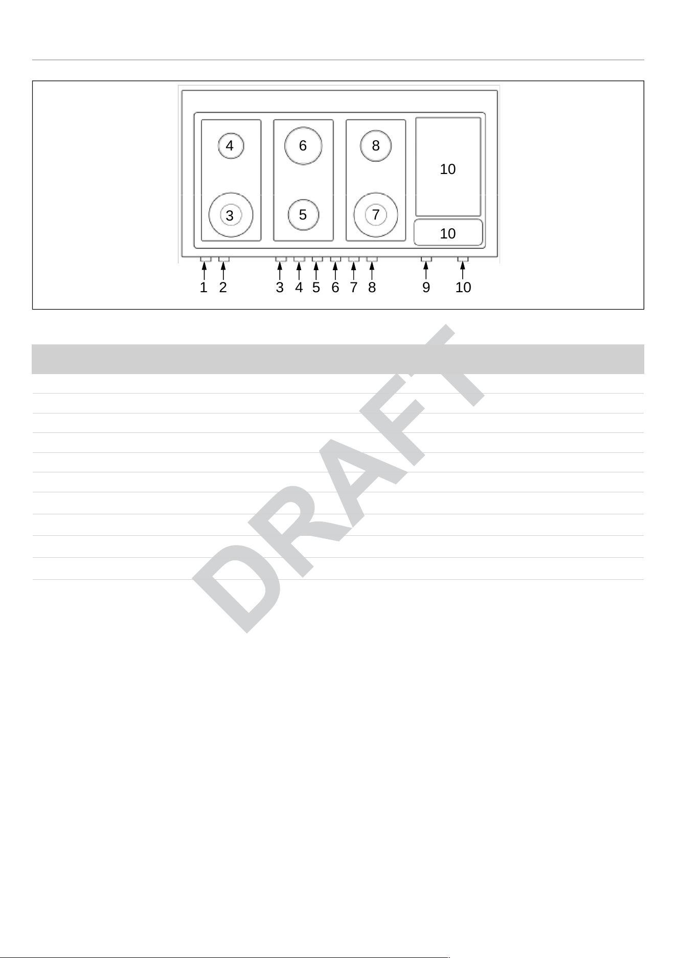
GAS COOKTOP
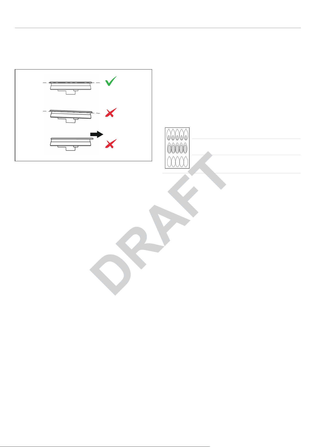
BURNER CAPS AND GRATES
The burners and the burner caps must be properly placed
for the cooktop to function properly.
Fig. 39
The burner grates must be properly placed inside the
recess on the cooktop.
MAKING SURE THE FLAME IS OPTIMAL
The flame should be stable with no excessive noise or
fluttering. The color should be blue with no yellow on the
tips. It is not uncommon to see orange in the flame color;
this indicates the burning of airborne impurities in the gas
and will disappear with use.
• With propane (LP) gas, slight yellow tips on the primary
icon are normal.
• The flame should burn completely around the burner cap.
If it does not, check that the cap is positioned correctly
on the base and that the ports are not blocked.
yellow flames: further adjustment is required
yellow tips on outer cones: normal for LP
gas
soft blue flames: normal for natural gas
The correct flame height depends on:
• size and material of pan being used
• food being cooked
• amount of liquid in the pan.
Never extend the flame beyond the base of the pan. Use a
low or medium flame for pan materials that conduct the
heat slowly, such as porcelain coated steel or glass-
ceramic.
Because the edges of the flame are much hotter than its
center, the flame tips should stay beneath the bottom of the
cookware. Flame tips which extend beyond the sides of the
cookware emit unnecessary heat into the room and can
also damage cookware handles, which increases the risk of
injury.
40
GAS COOKTOP
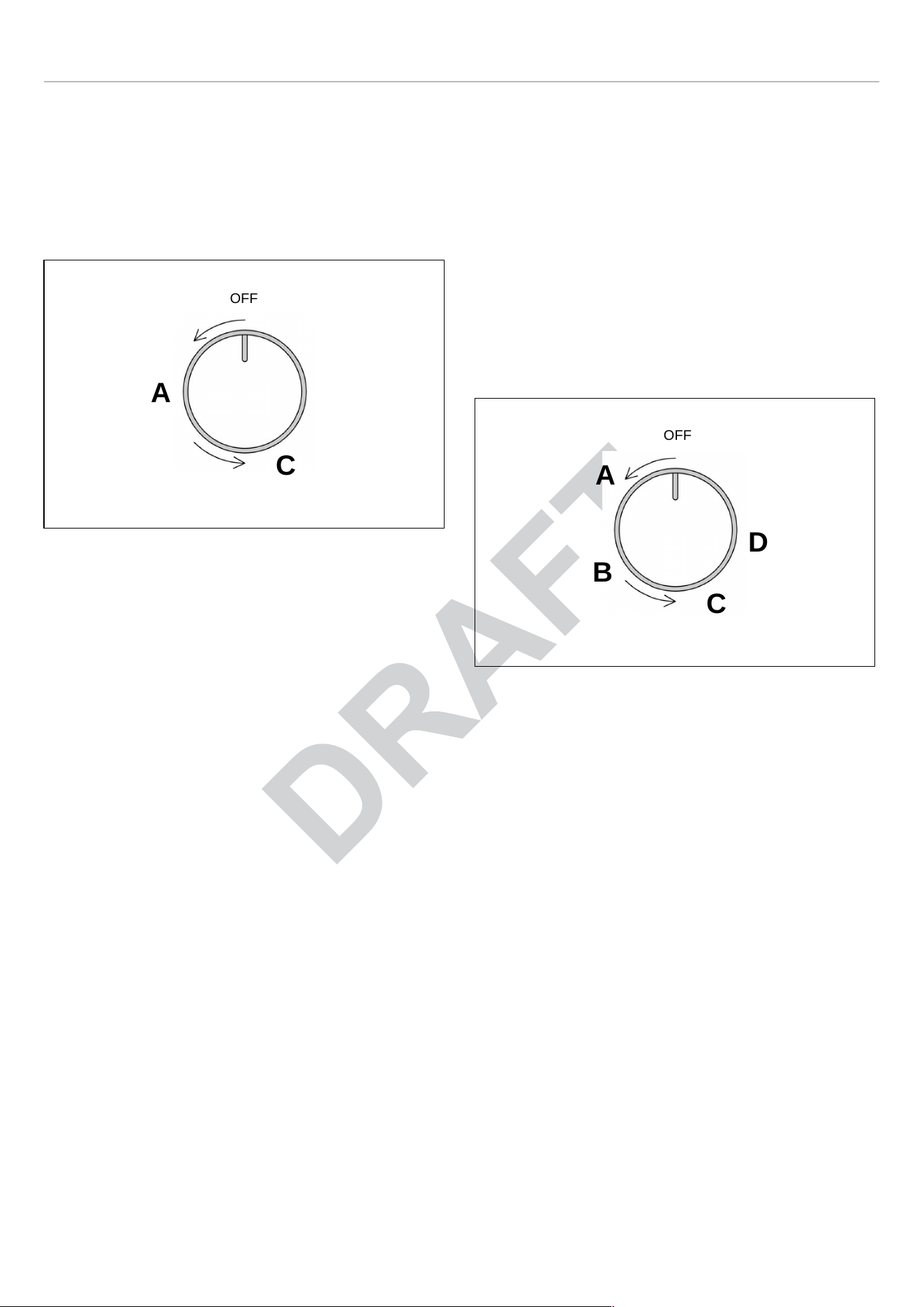
USING THE GAS BURNERS
• Press in the control knob and turn it anti-clockwise, to
HIGH position.
• Continue to hold the knob in for 5 to 10 seconds after the
burner ignition before releasing.
• Adjust flame with the knob as needed.
Fig. 40
• A — high
• C — low
USING THE POWER BURNERS
To give further flexibility, the dual power burner can be used
as a single simmer burner if the central burner alone is
ignited or as a power burner if the outer burner is also
ignited.
To light the central burner, press in the control knob and
turn it anti-clockwise to the HIGH of the single ring position.
Continue to hold the knob in for 5 to 10 seconds after the
burner ignites before releasing.
To also light the outer burner, turn the knob to the HIGH
double ring. Adjust the flame as required.
Fig. 41
A. high central
B. low central
C. high central-outer
D. low central-outer
GAS SHUT-OFF SAFETY - THERMOCOUPLE
A flame failure device (thermocouple) on each burner acts
as a safety gas cut-off in case the flame is accidentally
blown out. A thermocouple detects the absence of a flame
and stops the supply of gas. The thermocouple must be
heated for a few seconds when the burner is ignited before
the knob is released.
A
OFF
C
A
B
C
D
OFF
41

GAS COOKTOP
USING SPECIALTY COOKWARE
WOKS
Either flat-based or round-bottom woks with the accessory
ring can be used on all models. Round bottom woks must
be used with a support ring. In some models the porcelain-
coated cast iron wok support ring must be purchased
separately.
SIMMER RING
For very slow cooking the porcelain coated simmer ring
should be used. In some models the porcelain- coated cast
iron simmer ring must be purchased separately. Simmer
ring must be used for pan with diameter less than 4 inches.
NOTE
In the event of a power failure, the burners
can be lit with a match or gas lighter. The
flame failure devices will continue to
function normally.
GAS BURNER DIMENSIONS AND RECOMMENDED PAN SIZE
BURNER
DIAM. IN (MM) DIAM. OF PAN UTILIZATION
Auxiliary
2″
(50 mm)
3″1/2–5″1/2
(90-140 mm)
Use with smaller pans for boiling and
simmering and the preparation of
sauces.
Semi-rapid
2″3/4
(70 mm)
5″1/2–10″1/4
(140-260 mm)
Use for normal frying and boiling in
medium and small pans.
Rapid
3″3/4
(95 mm)
7″1/8–10″1/4
(180-260 mm)
Use with large and medium pans of
water for frying and rapid boiling.
Dual inner/outer
1″11/16–5″1/2
(43-140 mm)
8″2/3–10″1/4
(220-260 mm)
Use with woks, griddles and frying pans
or for large pans and rapid boiling.
42
ELECTRIC GRIDDLE
Available on 48″ models only.
The electric stainless steel griddle is manufactured from 3/
16 inches stainless steel designed for maximum heat
retention. Use extreme caution when operating the griddle
to avoid burn hazard!
PREPARING THE GRIDDLE
• Check the griddle plate adjustment by pouring two
tablespoons of water on the back of the griddle plate.
The water should slowly roll into the grease tray.
• To adjust move the griddle plate to the side.
• Adjust the two screws under the back of the plate. Start
with one half turn counterclockwise of the screws.
Further adjustment should be made by one-quarter turn
until water slowly flows into the grease tray.
Fig. 42
SEASONING THE GRIDDLE
The stainless steel griddle must be seasoned before using
it for the first time. We also recommend re-seasoning after
a long time of non use.
• Clean the griddle thoroughly with hot water and soap
solution to remove any protective coating.
• Rinse with a mixture ¼ gal of water and 1 cup white
vinegar and dry thoroughly.
• Pour 1 tsp vegetable oil into the centre of the griddle.
Rub the oil over the entire surface of the griddle using a
heavy cloth.
• Turn the control knob to a maximum setting.
• Turn the heat off when the oil begins to smoke. Allow the
griddle to cool.
• Repeat step 3 covering the entire surface with the oil.
Turn off the heat and allow the griddle to cool.
• Wipe the entire surface of the griddle using a heavy cloth.
• Apply a very thin layer of vegetable oil. The griddle is
now ready for use, too much oil can damage the griddle.
USING THE ELECTRIC GRIDDLE
Press and turn the knob (Fig. 43 ) anti-clockwise to the
selected position. The activation of the griddle is shown by
the indicator light which is also found on the front panel of
the appliance.
Pre-heat at the maximum temperature for 15 minutes, then
place the food on the griddle and cook at the desired
temperature.
Fig. 43
You can cook on the electric griddle without butter,
margarine or oil. However, a very small amount may be
used to flavor foods.
DO NOT use metal utensils on the griddle surface. Care
should be taken that the surface is not scratched or gouged
with utensils.
DO NOT use knives for cutting directly on the griddle plate.
OFF
43

ELECTRIC GRIDDLE
RECOMMENDED GRIDDLE TEMPERATURES
FOOD KNOB POSITION SETTING
Eggs
3
300℉ to 320℉ (150℃ to 160℃)
Bacon; Breakfast Sausage
3-4
350℉ to 375℉ (177℃ to 190℃)
Toasted Sandwiches 3
320℉ to 350℉ (160℃ to 177℃)
Boneless Chicken Breasts 3-4
350℉ to 375℉ (177℃ to 190℃)
Boneless Pork Chops (15 mm thick)
3-4
350℉ to 375℉ (177℃ to 190℃)
Ham Slices (15 mm thick)
3-4
350℉ to 375℉ (177℃ to 190℃)
Pancakes; FrenchToast
3-4
350℉ to 375℉ (177℃ to 190℃)
Potatoes; Hash Browns
4-5
375℉ to 400℉ (190℃ to 205℃)
44
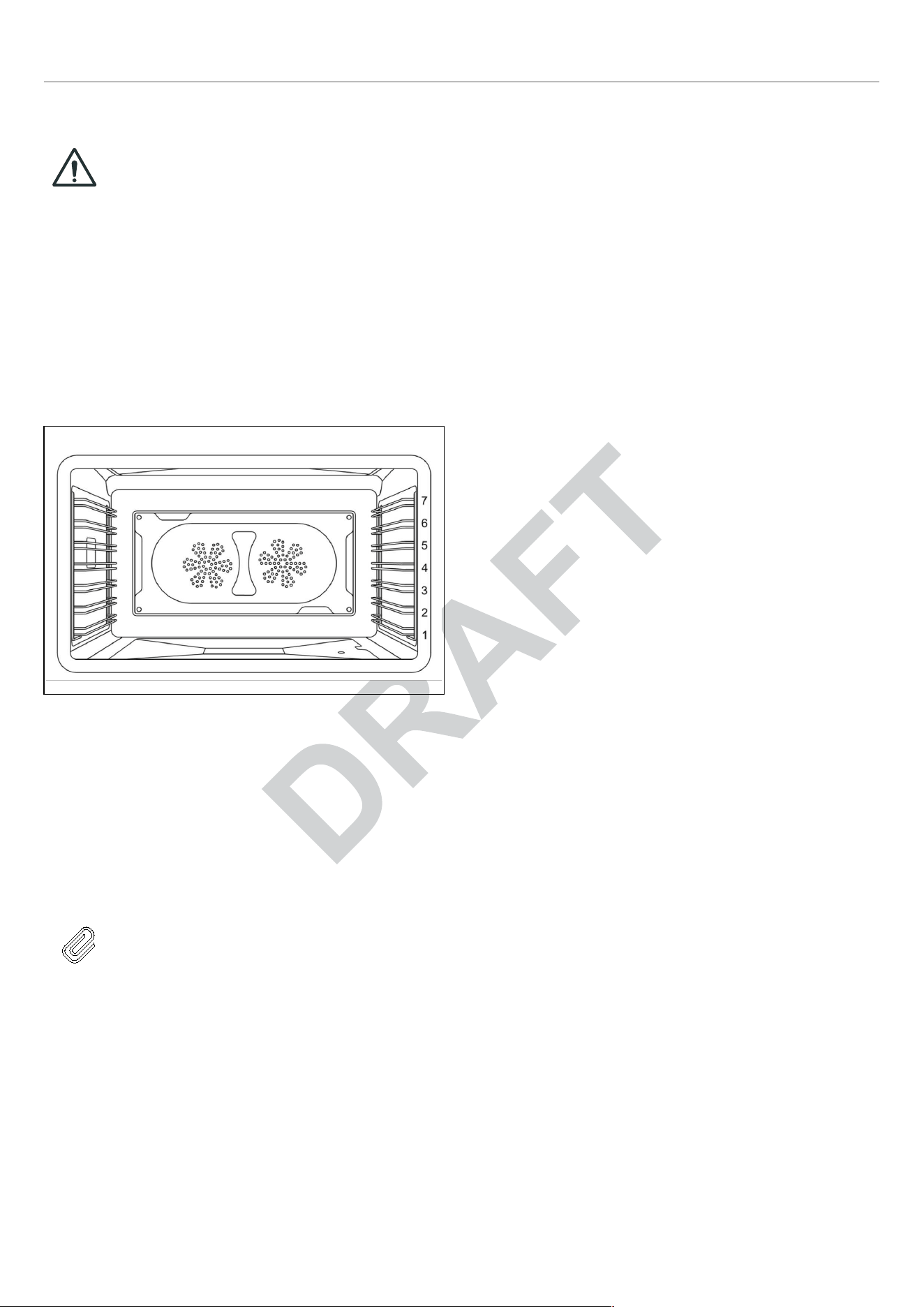
ELECTRIC OVEN
MAIN ELECTRIC OVEN
CAUTION
When using the oven for the first time it
should be operated for 15-30 minutes at
a temperature of about 500℉/260℃
without cooking anything inside in order
to eliminate any moisture and odors
from the internal insulation.
SHELVES POSITIONS
Shelves are mounted on the appropriate guides situated on
the sides of the oven compartment. Insert the shelf
between top and bottom guide in any of the 7 positions
indicated.
Fig. 44
COOLING FAN
Automatic operation of the cooling fan. The range cooker is
equipped with a thermostatically controlled cooling fan
designed to prevent the control panel and knobs from
overheating. The cooling fan will operate when the oven
temperature groves up. It will turn off when the temperature
decreases.
NOTE
It is normal for the cooling process to push
heated air out into the room when the oven
is on.
PREHEATING THE OVEN
Most cooking times in recipes are intended for a preheated
oven and require that the oven already be at the set
temperature before placing food in the oven. Preheating
time depends on the temperature setting and the number of
racks in the oven.
USING THE OVEN
1) Place rack in desired position and shut the door.
2) Select the oven function with the dedicated function knob.
The light in the cavity will turn on.
3) Set the desired temperature with the dedicated selector
knob.
This appliance is equipped with 1 indicator light on the front
panel. Light on indicates that the oven heating element/s
are activated.
45

ELECTRIC OVEN
OVEN COOKING MODES
The oven is equipped with several elements, used alone or
in combination to create different cooking modes:
• Upper bake burner
• Lower bake burner
• Broil element
The temperature setting and cooking times can vary
slightly from one oven to another. It is possible that
recipes and cooking times need to be adjusted
accordingly.
PRE-HEAT
Use this setting for fast pre-heating the oven. This function
provides the most efficient and fastest way to preheat the
cavity. Preheat function is unsuitable for use as a cooking
function.
BAKE
Heat from bake burner only.
Use this setting for baking, roasting, and casseroles.
The BAKE mode is best for baking on one rack:
• Standard baking: level 3 or 4
• Baking tall items: level 3
• Pies: level 2 or 3
• Large cuts of meat or poultry: level 2.
BOTTOM BAKE
Heat from lower element only.
Use this setting at low temperatures for slow-cooking
casseroles, custards or for warming plates. Use at high
temperatures for cooking sweet and savory pastry tarts.
Use at high temperatures for cooking sweet and savory
pastry tarts.
Use the same rack position as BAKE mode.
UPPER BAKE
Heat from upper element only.
Use this setting for browning and reheating dishes such as
lasagne, moussaka and cauliflower cheese.
The up Bake mode is best for baking on one rack.
• Standard bake, level 3 or 4
• Tall items, level 3
• Pies, level 4 or 5 to ensure the top of the crust is done
without over-browning the bottom.
BROIL
Heat from the broil element only.
The BROIL setting creates intense heat from the top of the
cavity. The broil mode is effective when food is placed on
upper racks.
• Beef steaks, ground meat patties, and lamb chops 1
inch or less: level 6.
• Meat 1 inches or more thick, fish, poultry, pork chops,
ham steaks 1 inch or more: level 5.
• Browning food: level 6 (no longer than 15 mins).
CONVECTION BROIL
Heat from broil element and air flow convection with fan.
Use this setting for browning and cooking evenly food on all
sides, including bottom. Also recommended for food that is
too delicate to turn over such as fish. The fan circulates hot
air around the food helping to cook it all the way through.
The degree of browning on each side might be different.
The conv broil mode must be used on one rack,
• sausages and chicken portions: level 5 or 6
• foods with high water content such as bacon and chops:
level 5 or 6 (door closed 400℉).
CONVECTION BAKE
Heat from bake burner and airflow convection with fan.
Cooking with convection has several advantages. In the
convection system, two fans in the back of the oven move
heated air evenly around the cavity, eliminating hot and
cold spots and ensuring temperature is even. Multiple
dishes can be cooked at the same time on different levels,
without having to rotate the pans. For convection, use
shallow bakeware to reduce heat shadows.
Food cooked uncovered will brown evenly and form a nice
crust. Food placed in covered bakeware or delicate
custards do not benefit from convection cooking.
Preheat the oven as for BAKE and turn the function knob to
‘CONVECTION’ before placing the food in the cavity.
• Single rack: use the same rack position as bake
• 2 racks: use level 2 and 4
• 3 racks : use level 1, 3, 5.
CONVECTION
Heat from the convection element and airflow convection
with fan.
Use this mode for most recipes being careful at calibrating
the time. Less time is usually required to reach the desired
result when using convection. The temperature is kept
uniform throughout the oven, which is particularly suitable
for baking on several levels or for batch cooking.
46
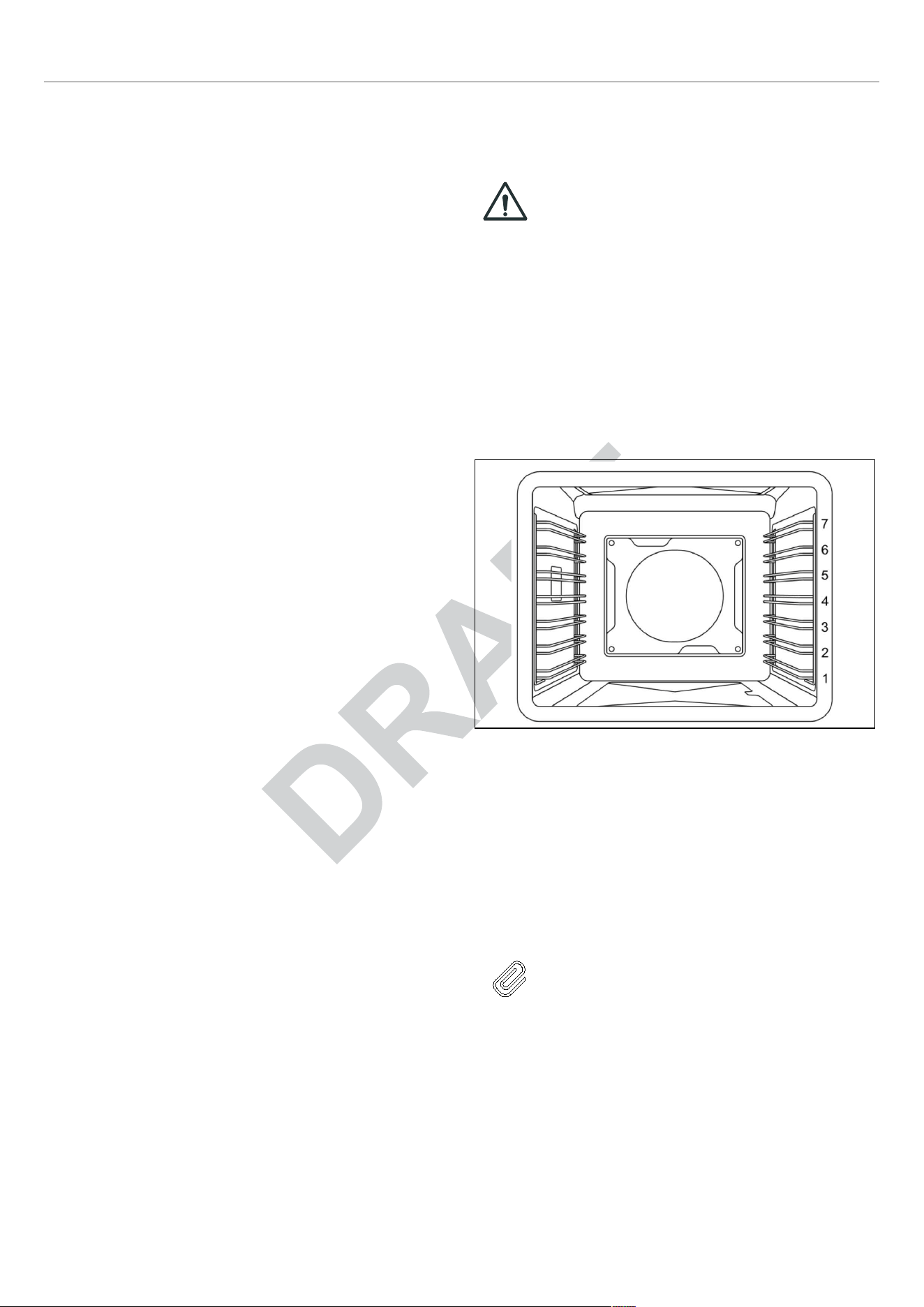
ELECTRIC OVEN
• Single rack: use the same rack position as bake
• 2 racks: use level 3 and 5
• 3 racks: use level 2, 4, 6.
PIZZA
Heat from lower bake element and circular element and
airflow convection with fan.
Use for cooking pizza, pastry or flat breads to get a
perfectly cooked base.
Use level 3 or level 2 to ensure the bottom of the crust is
done.
SPECIAL FUNCTIONS
LIGHT
Use this function to light the oven when the oven is off (for
example to clean the oven). Turn the function knob to
‘bake’. DO NOT turn on Oven Temperature Control Knob.
PROOFING
The proof feature maintains the warm, needed for proofing
yeast. It is best to start with a cool oven when using the
proofing function. Turn the function knob to ‘light’. DO NOT
turn on Oven Temperature Control Knob. Do not open the
oven door unnecessarily.
CONVECTION DEFROST
Air is circulated by the airflow fans. The fan accelerates
natural defrosting of food without heat. DO NOT leave
defrosted food in the oven for more than two hours. Place
the frozen food on a baking sheet. Turn the function knob to
‘CONV’. DO NOT turn on Oven Temperature Control Knob.
AUXILIARY ELECTRIC OVEN
Available on 48″ models only
CAUTION
When using the oven for the first time it
should be operated for 15-30 minutes at a
temperature of about 500℉/260℃ without
cooking anything inside in order to
eliminate any moisture and odors from the
internal insulation.
SHELVES POSITIONS
Shelves are mounted on the appropriate guides situated on
the sides of the oven compartment. Insert the shelf
between top and bottom guide in any of the 7 positions
indicated.
Fig. 45
COOLING FAN
Automatic operation of the cooling fan. The range cooker is
equipped with a thermostatically controlled cooling fan
designed to prevent the control panel and knobs from
overheating. The cooling fan will operate when the oven
temperature rises. It will turn off when the temperature
decreases.
NOTE
It is normal for the cooling process to push
heated air out into the room when the oven
is on.
PREHEATING THE OVEN
Most cooking times in recipes are intended for a preheated
oven and require that the oven already be at the set
temperature before placing food in the oven. Preheating
time depends on the temperature setting and the number of
racks in the oven.
47

ELECTRIC OVEN
USING THE OVEN
1) Place rack in desired position and shut the door.
2) The electric oven is controlled by an electric thermostat
combined with a switch. Select the oven function
/temperature with the dedicated knob. The light in the
cavity will turn on.
OVEN COOKING MODES
The oven is equipped with 3 heating elements, used alone
or in combination to create different cooking modes:
• Upper bake element
• Lower bake element
• Broil element.
The temperature setting and cooking times can vary slightly
from one oven to another. It is possible that recipes and
cooking times need to be adjusted accordingly.
BAKE (FROM 150℃ TO MAX)
Heat from upper and lower element.
Use this setting for baking, roasting, and casseroles on a
single rack.
• Standard bake: level 3 or 4
• Taller items: level 3
• Pies: level 2 or 3 to ensure the bottom of the crust is
done without over-browning the top
• Large cuts of meat or poultry: level 2.
BOTTOM BAKE
Heat from lower element.
In this function the temperature is fixed at max. setting
(500℉/260℃).
Use on a single rack.
• Standard bake: level 1 or 2.
UPPER BAKE
Heat from upper element only.
In this function the temperature is fixed at max. setting
(500℉/260℃).
Use on a single rack.
• Standard bake: level 5 or 6.
BROIL
Heat from the broil element only.
The BROIL setting creates intense heat from the top of the
cavity. The broil mode is effective when food is placed on
upper racks.
• Beef steaks, ground meat patties, and lamb chops 1
inch or less: level 6.
• Meat 1 inches or more thick, fish, poultry, pork chops,
ham steaks 1 inch or more: level 5.
• Browning food: level 6 (no longer than 15 mins).
48

ELECTRIC OVEN
LIGHT
Use this function to light the oven when the oven is off (for
example to manual clean the oven).
CONDENSATION
It is normal for a certain amount of moisture to evaporate
from the food during any cooking process. The amount
depends on the moisture content of the food. The moisture
will condense on any surface cooler than the inside of the
oven, such as the control panel.
USING ALUMINUM FOIL IN THE OVEN
Foil can be used to cover food in the oven but this should
not come into close proximity with the oven elements. Foil
should not be used to line the oven cavity or grill pan. This
can cause overheating, buckling and cracking of the
enamel surfaces.
GETTING THE BEST RESULTS
• Minimize opening and closing the oven door during
operation.
• Use the rack position recommended by the recipe and
fine-tune with personal experience.
• Use the bakeware recommended in the recipe.
• Store the broiler pan (s) outside the oven. An extra pan
without food will impact browning and cooking.
• For tender, golden brown crusts, use light non-stick/
anodized or shiny metal pans.
• For brown crisp crusts, use dark non-stick/anodized or
dark, dull metal pans or glass bakeware. These may
require lowering the bake temperature 25℉ (14℃).
• Allow at least 1″ (25.4 mm) of space between the pans
and the oven walls so heat can circulate around each
pan.
• To keep the oven as clean as possible, cook meat on a
pan and not directly on the racks.
• Cooking will continue with residual heat. remove the dish
from the oven immediately to avoid overcooking.
OVEN COOKING RECOMMENDATIONS
FOOD PAN SIZE CONTROL
TEMPERATURE SETTING
TOTAL SUGGESTED
COOKING TIME
Cookies 12″x15″ Cookie Sheet 375℉ 8 to 12 minutes
Layer Cakes 8″or 9″ Round 350℉ 25 to 35 minutes
Sheet Cakes
9″x13″ Pan 350℉ 30 to 40 minutes
Bunt Cakes 12 Cup
325℉ 60 to 75 minutes
Brownies or Bar Cookies 9″x9″ Pan 325℉ 20 to 25 minutes
Biscuits
12″x15″ Cookie Sheet
425℉ or Package Directions 10 to 15 minutes
Quick Bread 8″x4″ Loaf Pan
350℉ 55 to 70 minutes
Muffins 12 cup Muffin Pan
425℉ 14 to 19 minutes
Fruit Pies 9″ Diameter 425℉ 35 to 45 minutes
Fruit Cobblers 9″x9″ Pan 400℉ 25 to 30 minutes
Yeast Bread, Loaves
8″x4″ Loaf Pan 375℉ 25 to 30 minutes
Dinner Rolls 9″x13″ Pan 400℉ 12 to 18 minutes
Cinnamon Rolls
9″x13″ Pan 375℉ 25 to 30 minutes
Yeast Cotter and Cake 12″x15″ Cookie Sheet
400℉ 20 to 30 minutes
49

ELECTRIC OVEN
BROILING RECOMMENDATION
FOOD ITEM CONTROL
TEMPERATURE SETTING
SELECTOR
APPROXIMATE COOKING
TIME
SPECIAL INSTRUCTIONS
AND TIPS
BEEF
Ground Beef Patties, ½″
thick
500℉ fixed temperature
setting
15 to 20 minutes Broil until no pink in center
T-Bone Steak 500℉ fixed temperature
setting
12 to 20 minutes Time depends on rareness
of steak
Flank Steak 500℉ fixed temperature
setting
12 to 20 minutes Rare to Medium Rare
Eye of Round Roast
325℉
20 to 25 min/lb Small roasts take more
minutes per pound; reduce
time by using Convection
Bake
PORK Loin Roast 325℉ 20 to 25 min/lb Cook until juices are clear
POULTRY
Boneless Skinless
Chicken Breasts
500℉ fixed temperature
setting
20 to 25 minutes
Cook until juices are clear
Chicken Thighs 500℉ fixed temperature
setting
25 to 30 minutes
Remove skin; Cook until
juices are clear
Half Chickens 500℉ fixed temperature
setting
30 to 45 minutes
Turn with tongs; Cook until
juices are clear
Roast Chicken 350℉ 75 to 90 minutes Do not stuff; reduce time by
using Convection Bake
Turkey 325℉ 20 to 25 min/lb Do not stuff; reduce time by
using Convection Bake
50

ELECTRIC OVEN
AIR FRY RECOMMENDATIONS
ITEM
AMOUNT
TEMPERATURE TIME
Potatoes
Frozen French Fries Frozen 30-35 oz 420℉–440℉ 15-25 min
French Fries, Seasoned 25-30 oz 420℉–440℉ 20-25 min
Frozen Tater Tots 40–45 oz 400℉–430℉ 20-25 min
Frozen Hash Browns 25–30 oz 420℉–440℉ 20-25 min
Frozen Potato Wedges 30–35 oz 420℉–440℉ 20-25 min
Homemade French Fries*
20–25 oz 380℉–400℉ 25–30 min
Homemade Potato
Wedges*
20–25 oz 380℉–400℉ 25–30 min
Frozen food
Frozen Chicken Nuggets
25–30 oz 400℉–440℉ 10–15 min
Frozen Chicken Wings
30–35 oz 400℉–430℉ 20–30 min
Frozen Onion Rings 20–25 oz 380℉–400℉ 15–20 min
Frozen Fish Fingers 20–25 oz 380℉–400℉ 18–22 min
Frozen Chicken Strips
25–30 oz 400℉–430℉ 20–30 min
Frozen Churros 20–25 oz 380℉–400℉ 18–22 min
TROUBLESHOOTING COMMON PROBLEMS WITH OVEN COOKING
PROBLEMS CAUSE
REMEDY
Cakes burned on the sides or not
done in center
Oven too hot
Wrong pan size
Reduce temperature
Use recommended pan size
Cakes crack on top
Batter too thick
Oven too hot
Wrong pan size
Follow recipe or add liquid
Reduce temperature
Use recommended pan size
Food too brown on bottom
Oven door opened too often
Incorrect rack position
Wrong bake setting
Use door window to check food
Use recommended rack position
Adjust to conventional or convection
setting as needed
Food too brown on top Incorrect rack position
Oven not preheated
Use recommended rack position
Allow oven to preheat
Cookies too flat
Hot cookie sheet Allow sheet to cool between batches
Pies burned around edges
Oven too hot
Oven not preheated
Reduce temperature
Allow oven to preheat
Pies too light on top
Oven not hot enough
Oven not preheated
Increase temperature
Allow oven to preheat
51
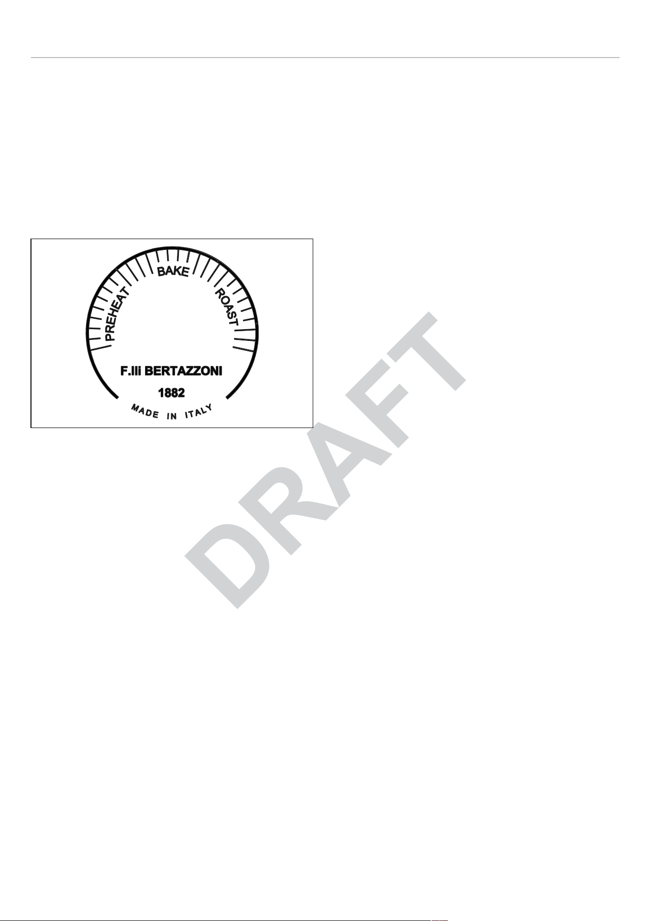
ELECTRIC OVEN
OVEN TEMPERATURE GAUGE
The oven temperature gauge measures the temperature in
the oven cavity, and provides an useful indication of when
the cavity is adequately pre-heated and actual baking or
roasting may start. The temperature ranges on the dial are:
• BAKE 300-400℉
• ROAST 425-500℉
It is normal that you may see fluctuations in the needle as
the oven cycles
Fig. 46
TELESCOPIC GLIDES
The telescopic glides fit any shelf level and work with the
wire shelves provided as standard equipment.
FITTING THE GLIDES
1) Locate the two spring clips at the front and back of the
glides.
2) Locate the pin on the glide that indicates the back.
3) Choose the right level and position the telescopic glide
near the upper wire.
4) Insert the rear spring clip on the glide.
5) Gently insert the front spring clip on the glide.
6) Pull and push each glide to ensure the correct
installation and smooth operation.
7) Extract both glides to the fully extended position and
place the shelf over them, making sure it is accurately
placed between the rear pin and the front pin.
52
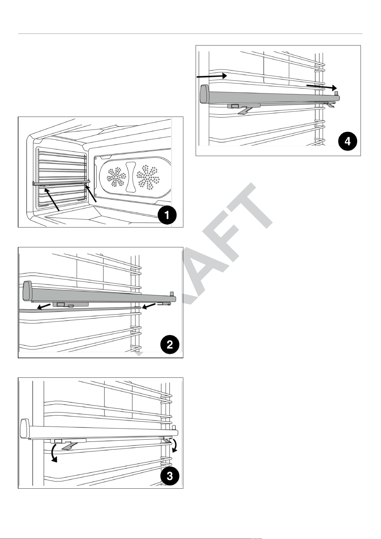
ELECTRIC OVEN
REMOVING THE GLIDES
1) Locate the two spring clips at the front and back of the
glide.
2) Gently pull down the front spring clip.
3) Pull the glide away from the oven side - be careful not to
strain the clip.
4) Repeat steps 2 - 3 on rear spring clip to remove glide.
Fig. 47
Fig. 48
Fig. 49
Fig. 50
53

KEEPING YOUR BERTAZZONI CLEAN
BURN HAZARD
Make sure the heating elements are turned off and allowed
to cool completely before any cleaning and/or maintenance
operation.
THINGS TO AVOID
• Do not use a steam cleaner to clean the range: the
steam could reach electrical components and cause a
short.
• Do not spray liquids such as cleaning agents into the
openings on the bottom and top of the oven cavity.
• All surfaces can discolor or be damaged if unsuitable
cleaning agents are used. The front of the oven, in
particular, will be damaged by oven cleaners and
descalers. All surfaces are susceptible to scratching.
Scratches on glass surfaces may cause a breakage.
Immediately remove any residues by using suitable
cleaning products.
• The heating elements in the oven do not require
cleaning. The elements burn off any residue when the
oven is in use.
CLEANING STAINLESS STEEL
All stainless steel parts should be wiped with hot water and
soap solution at the end of each cycle. Wipe up spills and
boilovers immediately. Use suitable, non-abrasive stainless
cleaning products when water and soap solution will not do
the job. DO NOT use steel wool, abrasive cloths, cleansers,
or powders. If necessary, scrape stainless steel to remove
encrusted materials, soak the area with hot towels to soften
the residue, then use a wooden or nylon spatula or scraper.
DO NOT use a metal knife, spatula, or any other metal tool
to scrape stainless steel. DO NOT permit citrus or tomato
juice to remain on stainless steel surface, as citric acid will
permanently discolor stainless steel.
CLEANING PAINTED SURFACES
Clean with a soft cloth, warm water and non-abrasive
dishwashing liquid. Whilst still damp, polish dry with a clean
soft cloth.
CLEANING GLASS SURFACES
Clean with cleaning detergent and warm water. Glass
cleaner can be used to remove fingerprints. If using glass
cleaner containing ammonia, make sure that it does not
drip on exterior door surface.
CLEANING THE BROILER PAN
Clean with detergent and hot water. For stubborn spots,
use a soap-filled steel wool pad.
The porcelain enamel finish is acid resistant, but not acid
proof. Acidic foods, such as citrus juices, tomatoes,
rhubarb, vinegar, alcohol or milk, should be wiped up and
not allowed to bake onto the porcelain during the next use.
CLEANING THE STAINLESS STEEL GRIDDLE
The stainless steel griddle is quite heavy and it can be
cleaned in place without removing it. After cooking, allow
the Griddle to cool until just warm. Use a spatula to remove
any cooking residue. Wipe away any fat in the drip tray with
paper towels. Clean the entire surface with warm water and
dishwashing liquid, using a stainless steel scourer. Always
work with the grain of the stainless steel. Certain types of
food with high sodium content such as bacon may leave
white marks. For these and other stubborn marks, use a
cream cleaner suitable for stainless steel surfaces.
CLEANING THE OVEN CAVITY
• Always allow the oven interior to cool before cleaning.
• Do not allow vinegar, wine, coffee, milk, salt water or fruit
juices to remain in contact with enamelled surfaces for
prolonged periods as they may stain or discolor the
surface.
• Never use sharp utensils to remove stains as this could
scratch the surface.
• Never use steam cleaners on the oven interiors as
steam may damage electronic parts.
• For light cleaning, wipe with a soft cloth, using warm
water and washing up liquid. For heavier residues, use a
cream cleaner and a nylon scourer.
• Oven cleaning products can be used according to the
manufacturer’s directions but care should be taken that
they do not come in contact with any stainless steel,
chrome, painted or alloy parts of the range or the door
seals and elements.
CLEANING OVEN RACKS AND SUPPORTS
Clean with detergent and hot water. Stubborn spots can be
scoured with a soap-filled steel wool pad.
54

SIMPLE MAINTENANCE
Keeping appliance area clear and free from combustible
materials, gasoline and other flammable vapors or liquids.
Not obstructing the flow of combustion and ventilation air.
These simple tasks can be performed by the owner. For
any other maintenance task, we recommend employing a
trained service technician. Please call our toll free line to
identify service technicians in your area:
If located in the USA
866 905 0010
https://us.bertazzoni.com/more/support
If located in CANADA
800 561 7265
https://ca.bertazzoni.com/more/support
REPLACING OVEN LIGHTS
WARNING
Electric shock hazard!
Disconnect the electric power at the main
fuse or circuit breaker before replacing bulb.
DO NOT touch bulb with bare hands. Clean
off any signs of oil from the bulb and handle
with a soft cloth.
55
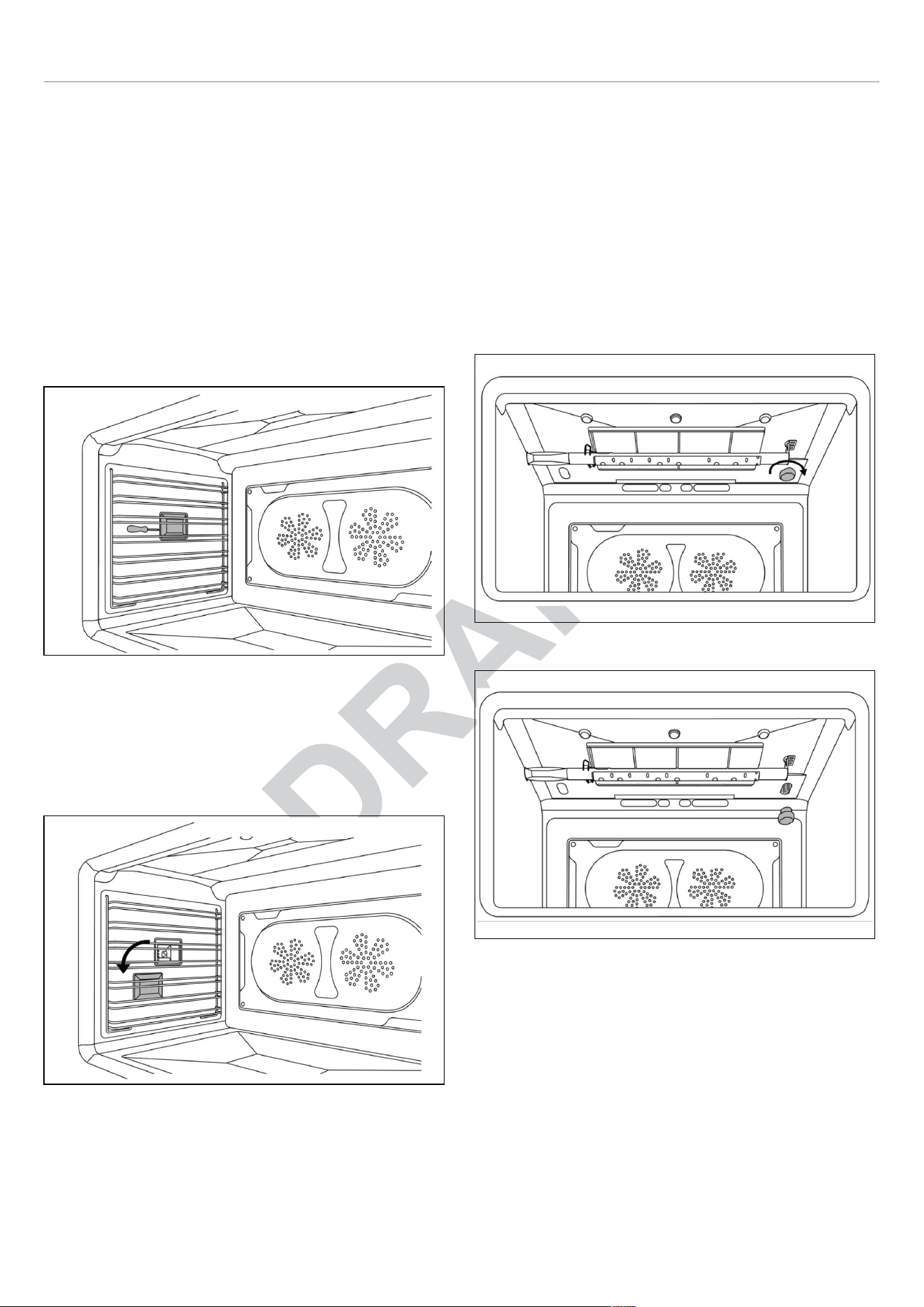
SIMPLE MAINTENANCE
SIDE OVEN LIGHT
Bulb type: halogen G9 120 V, 40 W
• Make sure the heating elements are turned off and
allowed to cool completely. Disconnect the appliance
from the power supply. Remove the oven rack if it
interferes with the light housing.
• Slide the tip of a flat screw driver between the glass
cover and the lamp housing. Gently twist the screw
driver tip to loosen the glass lens cover, holding it in
place with your fingers to prevent it from falling and
breaking.
• Remove the glass lens cover and then remove the
halogen bulb.
Fig. 51
• Place a new halogen bulb in its slot. DO NOT touch bulb
with bare hands.
• Press the glass cover back into place and replace the
oven rack.
• Reconnect the oven to the electrical supply.
Fig. 52
TOP OVEN LIGHT
Bulb type: halogen G9 120 V, 40 W
• Make sure the heating elements are turned off and
allowed to cool completely. Disconnect the appliance
from the power supply.
• Unscrew the glass cover and remove the halogen bulb.
• Place a new halogen bulb in its slot. DO NOT touch bulb
with bare hands.
• Screw the glass cover back in place.
• Reconnect the oven to the electrical supply.
Fig. 53
Fig. 54
56

TROUBLESHOOTING
Here are answer to common problems you may experience.
You are also welcome to call our toll free Customer Service
line to troubleshoot any issue with your Bertazzoni.
If located in the USA
866 905 0010
https://us.bertazzoni.com/more/support
If located in CANADA
800 561 7265
https://ca.bertazzoni.com/more/support
THE OVEN WILL NOT OPERATE
Is there power to the range? Are the igniters or burner
holes blocked? Check the switch fuse or circuit breaker.
THE SURFER BURNERS WILL NOT IGNITE
Is there power to the range? Are the igniters or burner
holes blocked? Are the burner rings and burner caps
seated firmly? Check the switch fuse or circuit breaker.
Check that the igniter is clean and the burner holes are
open and clean of any residue.
THE BURNER IGNITES BUT SWITCHES OFF
WHEN THE KNOB IS RELEASED
The burners have flame failure devices fitted as standard.
Therefore, after lighting the burner, keep the knob pressed
for a few seconds to deactivate the flame failure device.
THE IGNITION CANDLES ARE SPARKING
CONTINUOUSLY
Is the cooktop wet from cleaning or a boil over? Turn off the
electricity supply and thoroughly dry the burner
components and igniters.
THE CONTROL KNOBS ARE GETTING TOO
HOT
Are you cooking with the oven door open? Keep the oven
door shut when not in use or when grilling/broiling.
A CONTROL KNOB IS LOOSE ON ITS SHAFT
The knob retaining spring clip may have been damaged.
Call our service department for advice and a replacement if
necessary.
FOOD IS COOKING TOO QUICKLY
Are you using a convection mode?
When using a fan-assisted oven cooking mode, it is
recommended to reduce the cooking temperature by 70℉
(20℃) compared to conventional cooking.
FOOD IS NOT COOKING EVENLY
Are you cooking large amount of food or are you using
large bakeware?
Air needs to circulate through the oven for even cooking.
Remove the grill pan from the oven when not in use and
always allow a gap on all four sides of dishes. You may
need to turn your bakeware during the cooking cycle.
Oversized baking sheets, roasting pans and cakeware will
act as a baffle and prevent hot air from moving evenly
around the cavity. Choose cooking equipment that allows a
minimum of 1 inch (2.5 cm) space on all sides to allow the
free movement of heat inside the cavity.
GRILLING IN THE OVEN IS SLOW
Have you selected the correct function?
THE FAN CONTINUES TO RUN AFTER THE
OVEN IS SWITCHED OFF
This is normal. The cooling fan may run on and off for up to
30 minutes after the oven is switched off to keep the
controls cool.
CONDENSATION FORMS IN THE OVEN
Have you pre-heated the oven?
Condensation is less likely to form when the oven or grill is
pre-heated before use.
SMOKE IS GENERATED IN THE OVEN
Have you selected the right cooking temperature? Are you
cooking food with high fat? Do you rarely use the grill?
Have you cooked fat under the grill? Does the oven interior
need to be cleaned?
Remember to reduce the oven temperature by 70℉ (20℃)
if using a fan function with a recipe designed for
conventional cooking. Use high-sided dishes to contain fats
and splashes. Leave the grill on for a few minutes after
grilling or roasting to burn off fat deposits from the oven roof.
Oven surfaces should be cleaned regularly to prevent
build-up of cooking residues.
Please kindly register on our web site www.bertazzoni.com
to validate your new product warranty and help us to assist
you better in case of any inconvenience.
57


www.bertazzoni.com
Via Palazzina, 8,
42016 Guastalla RE
© 2024 BERTAZZONI. All rights reserved.
3100868_v.05