31-5000962 Rev. 0 02-25
NS16A
Air Conditioner R-454B
with Aluminum Coil
Service
Manual
READ CAREFULLY.
KEEP THESE INSTRUCTIONS
.
2 49-5000962 Rev. 0
This NS16A outdoor air conditioner with all-aluminum coil
is designed for use with R-454B refrigerant only. This unit
must be installed with an approved indoor air handler or coil.
These instructions are intended as a general guide and do
not supersede local codes in any way. Consult authorities
having jurisdiction before installation.
This outdoor unit is designed for use in systems that use the
following refrigerant metering device:
• Thermal expansion valve (TXV)
IMPORTANT: Special procedures are required for cleaning
the aluminum coil in this unit. See Page 30 in this manual
for information.
General Information
Improper installation, adjustment, alteration, service or
maintenance can cause property damage, personal injury
or loss of life. Installation and service must be performed
by a licensed professional installer (or equivalent), service
agency or the gas supplier.
WARNING
As with any mechanical equipment, contact with sharp
sheet metal edges can result in personal injury. Take
care while handling this equipment and wear gloves and
protective clothing.
CAUTION
Electric Shock Hazard. Can cause injury or
death. Unit must be properly grounded in
accordance with national and local codes.
Line voltage is present at all components
when unit is not in operation on units with
single-pole contactors. Disconnect all remote
electric power supplies before opening access
panel. Unit may have multiple power supplies.
WARNING
To prevent serious injury or death:
1. Lock-out/tag-out before performing maintenance.
2. If system power is required (e.g., smoke detector
maintenance), disable power to blower, remove fan
belt where applicable, and ensure all controllers
and thermostats are set to the “OFF” position before
performing maintenance.
3. Always keep hands, hair, clothing, jewelry, tools, etc.
away from moving parts.
WARNING
7KLVXQLWPXVWEHPDWFKHGZLWKDQLQGRRUFRLODVVSHFL¿HG
ZLWK $+5, )RU $+5, &HUWL¿HG V\VWHP PDWFKXSV YLVLW
AHRIDirectory.org.
IMPORTANT
49-5000962 Rev. 0 3
• Do not use means to accelerate the defrosting process
or to clean, other than those recommended by the
manufacturer.
• The appliance shall be stored in a room without
continuously operating ignition sources (for example:
RSHQÀDPHVDQRSHUDWLQJJDVDSSOLDQFHRUDQRSHUDWLQJ
electric heater).
• Do not pierce or burn.
• Be aware that refrigerants may not contain an odor.
WARNING
Ducts connected to an appliance shall not contain a
potential ignition source
WARNING
PARTIAL UNITS shall only be connected to an appliance
suitable for the same refrigerant.
WARNING
Ensure that the area is in the open or that it is adequately
ventilated before breaking into the system or conducting
any hot work. A degree of ventilation shall continue during
the period that the work is carried out.
IMPORTANT
Verify cabling will not be subject to wear, corrosion,
excessive pressure, vibration, sharp edges or any other
DGYHUVHHQYLURQPHQWDOHႇHFWV
IMPORTANT
Pipe work, including piping material, pipe routing,
and installation shall include protection from physical
damage in operation and service, and be in compliance
with national and local codes and standards, such as
ASHRAE 15, ASHRAE 15.2, IAPMO Uniform Mechanical
Code, ICC International Mechanical Code, or CSA B52.
$OO¿HOG MRLQWVVKDOOEHDFFHVVLEOH IRU LQVSHFWLRQSULRUWR
being covered or enclosed.
IMPORTANT
(YHU\ZRUNLQJSURFHGXUHWKDWDႇHFWVVDIHW\PHDQVVKDOO
only be carried out by competent persons. This appliance
is not to be used by persons (including children) with
reduced physical, sensory or mental capabilities, or
lack of experience and knowledge, unless they have
been given supervision or instruction concerning use of
the appliance by a person responsible for their safety.
Children should be supervised to ensure they do not play
with the appliance.
WARNING
Servicing shall be performed only as recommended by
the manufacturer.
CAUTION
Some soaps used for leak detection are corrosive to
certain metals. Carefully rinse piping thoroughly after leak
test has been completed. Do not use matches, candles,
ÀDPHRURWKHUVRXUFHVRILJQLWLRQWRFKHFNIRUJDVOHDNV
CAUTION
Under no circumstances shall potential sources of ignition
be used in the searching for or detection of refrigerant
leaks. A halide torch (or any other detector using a naked
ÀDPHVKDOOQRWEHXVHG
The following leak detection methods are deemed
acceptable for all refrigerant systems.
Electronic leak detectors may be used to detect refrigerant
OHDNV EXW LQ WKH FDVH RI ÀDPPDEOH UHIULJHUDQWV WKH
sensitivity may not be adequate, or may need recalibration.
(Detection equipment shall be calibrated in a refrigerant-
free area.) Ensure that the detector is not a potential
source of ignition and is suitable for the refrigerant used.
Leak detection equipment shall be set at a percentage of
the LFL of the refrigerant and shall be calibrated to the
refrigerant employed, and the appropriate percentage of
JDVPD[LPXPLVFRQ¿UPHG/HDNGHWHFWLRQÀXLGV
are also suitable for use with most refrigerants but the use
of detergents containing chlorine shall be avoided as the
chlorine may react with the refrigerant and corrode the
FRSSHUSLSHZRUN,IDOHDNLVVXVSHFWHGDOOQDNHGÀDPHV
shall be removed/extinguished. If a leakage of refrigerant
is found which requires brazing, all of the refrigerant shall
be recovered from the system, or isolated (by means of
VKXWRႇYDOYHVLQDSDUWRIWKHV\VWHPUHPRWHIURPWKH
leak.
CAUTION
4 49-5000962 Rev. 0
When breaking into the refrigerant circuit to make repairs
– or for any other purpose – conventional procedures
VKDOO EH XVHG +RZHYHU IRU ÀDPPDEOH UHIULJHUDQWV LW
is important that best practice be followed and, since
ÀDPPDELOLW\ LV D FRQVLGHUDWLRQ SURFHGXUHV VXFK DV
safely remove refrigerant following local and national
regulations, purging the circuit with inert gas, evacuating
(optional for A2L), purging with inert gas (optional for A2L),
or opening the circuit by cutting or brazing be adhered to.
The refrigerant charge shall be recovered into the correct
recovery cylinders if venting is not allowed by local and
QDWLRQDO FRGHV )RU DSSOLDQFHV FRQWDLQLQJ ÀDPPDEOH
refrigerants, the system shall be purged with oxygen-
IUHHQLWURJHQWRUHQGHUWKHDSSOLDQFHVDIHIRUÀDPPDEOH
refrigerants.
This process might need to be repeated several times.
Compressed air or oxygen shall not be used for purging
UHIULJHUDQWV\VWHPV)RUDSSOLDQFHVFRQWDLQLQJÀDPPDEOH
refrigerants, refrigerants purging shall be achieved by
breaking the vacuum in the system with oxygenfree
QLWURJHQDQGFRQWLQXLQJWR¿OOXQWLOWKHZRUNLQJSUHVVXUHLV
DFKLHYHGWKHQYHQWLQJWRDWPRVSKHUHDQG¿QDOO\SXOOLQJ
down to a vacuum (optional for A2L). This process shall be
repeated until no refrigerant is within the system (optional
IRU$/ :KHQ WKH ¿QDO R[\JHQIUHH QLWURJHQ FKDUJH LV
used, the system shall be vented down to atmospheric
pressure to enable work to take place. Ensure that the
outlet for the vacuum pump is not close to any potential
ignition sources and that ventilation is available.
IMPORTANT
$IWHU FRPSOHWLRQ RI ¿HOG SLSLQJ IRU VSOLW V\VWHPV WKH
¿HOGSLSHZRUNVKDOOEHSUHVVXUHWHVWHGZLWKDQLQHUWJDV
and then vacuum tested prior to refrigerant charging,
according to the following requirements;
– Field-made refrigerant joints indoors shall be tightness
tested. The test method shall have a sensitivity of .2
oz. per year of refrigerant or better, under pressure. No
leak shall be detected.
IMPORTANT
When removing refrigerant from a system, either for
servicing or decommissioning, it is recommended good
practice that all refrigerants are removed safely.
When transferring refrigerant into cylinders, ensure
that only appropriate refrigerant recovery cylinders are
employed. Ensure that the correct number of cylinders for
holding the total system charge is available. All cylinders
to be used are designated for the recovered refrigerant
and labelled for that refrigerant (i. e. special cylinders for
the recovery of refrigerant). Cylinders shall be complete
ZLWKSUHVVXUHUHOLHIYDOYHDQGDVVRFLDWHGVKXWRႇYDOYHV
in good working order. Empty recovery cylinders are
evacuated and, if possible, cooled before recovery
occurs.
The recovery equipment shall be in good working order
with a set of instructions concerning the equipment that
is at hand and shall be suitable for the recovery of all
appropriate refrigerants including, when applicable,
ÀDPPDEOH UHIULJHUDQWV ,Q DGGLWLRQ D VHW RI FDOLEUDWHG
weighing scales shall be available and in good working
order. Hoses shall be complete with leak-free disconnect
couplings and in good condition. Before using the recovery
machine, check that it is in satisfactory working order,
has been properly maintained and that any associated
electrical components are sealed to prevent ignition in the
event of a refrigerant release. Consult manufacturer if in
doubt.
The recovered refrigerant shall be returned to the
refrigerant supplier in the correct recovery cylinder,
and the relevant waste transfer note arranged. Do not
mix refrigerants in recovery units and especially not in
cylinders.
If compressors or compressor oils are to be removed,
ensure that they have been evacuated to an acceptable
OHYHO WR PDNH FHUWDLQ WKDW ÀDPPDEOH UHIULJHUDQW GRHV
not remain within the lubricant. The evacuation process
shall be carried out prior to returning the compressor
to thesuppliers. Only electric heating to the compressor
body shall be employed to accelerate this process. When
oil is drained from a system, it shall be carried out safely.
IMPORTANT
In addition to conventional charging procedures, the
following requirements shall be followed.
(QVXUH WKDW FRQWDPLQDWLRQ RI GLႇHUHQW UHIULJHUDQWV
does not occur when using charging equipment. Hoses
or lines shall be as short as possible to minimize the
amount of refrigerant contained in them.
• Cylinders shall be kept in an appropriate position
according to the instructions.
• Ensure that the REFRIGERATING SYSTEM is earthed
prior to charging the system with refrigerant.
• Label the system when charging is complete (if not
already).
([WUHPH FDUH VKDOO EH WDNHQ QRW WR RYHU¿OO WKH
REFRIGERATING SYSTEM.
Prior to recharging the system, it shall be pressuretested
with the appropriate purging gas. The system shall
be leak tested on completion of charging, but prior to
commissioning. A follow up leak test shall be carried out
prior to leaving the site.
IMPORTANT
49-5000962 Rev. 0 5
Prior to beginning work on systems containing
FLAMMABLE REFRIGERANTS, safety checks are
necessary to ensure that the risk of ignition is minimized.
IMPORTANT
$OOPDLQWHQDQFHVWDႇDQGRWKHUVZRUNLQJLQWKHORFDODUHD
shall be instructed on the nature of work being carried
RXW:RUNLQFRQ¿QHGVSDFHVVKDOOEHDYRLGHG
IMPORTANT
If any hot work is to be conducted on the refrigerating
HTXLSPHQW RU DQ\ DVVRFLDWHG SDUWV DSSURSULDWH ¿UH
extinguishing equipment shall be available to hand. Have
D GU\ SRZGHU RU &2ð ¿UH H[WLQJXLVKHU DGMDFHQW WR WKH
charging area.
IMPORTANT
Sealed electrical components shall be replaced.
IMPORTANT
Intrinsically safe components must be replaced.
IMPORTANT
Work shall be undertaken under a controlled procedure
VRDV WR PLQLPL]HWKHULVN RI D ÀDPPDEOHJDV RU YDSRU
being present while the work is being performed.
IMPORTANT
The area shall be checked with an appropriate refrigerant
detector prior to and during work, to ensure the technician
LVDZDUH RI SRWHQWLDOO\WR[LF RU ÀDPPDEOH DWPRVSKHUHV
Ensure that the leak detection equipment being used
is suitable for use with all applicable refrigerants, i.e.
nonsparking, adequately sealed or intrinsically safe.
IMPORTANT
No person carrying out work in relation to a
REFRIGERATING SYSTEM which involves exposing
any pipe work shall use any sources of ignition in such
DPDQQHUWKDWLWPD\OHDGWRWKHULVNRI¿UHRUH[SORVLRQ
All possible ignition sources, including cigarette
VPRNLQJ VKRXOG EH NHSW VXႈFLHQWO\ IDU DZD\ IURP WKH
site of installation, repairing, removing and disposal,
during which refrigerant can possibly be released to the
surrounding space. Prior to work taking place, the area
around the equipment is to be surveyed to make sure
WKDWWKHUHDUHQRÀDPPDEOHKD]DUGVRULJQLWLRQULVNV³1R
Smoking” signs shall be displayed.
IMPORTANT
Where electrical components are being changed, they
VKDOOEH¿WIRUWKHSXUSRVHDQGWRWKHFRUUHFWVSHFL¿FDWLRQ
At all times the manufacturer’s maintenance and service
guidelines shall be followed. If in doubt, consult the
manufacturer’s technical department for assistance.
The following checks shall be applied to installations
using FLAMMABLE REFRIGERANTS:
– the actual REFRIGERANT CHARGE is in accordance
with the room size within which the refrigerant containing
parts are installed;
– the ventilation machinery and outlets are operating
adequately and are not obstructed;
– if an indirect refrigerating circuit is being used, the
secondary circuit shall be checked for the presence of
refrigerant;
– marking to the equipment continues to be visible and
legible. Markings and signs that are illegible shall be
corrected;
– refrigerating pipe or components are installed in a
position where they are unlikely to be exposed to any
substance which may corrode refrigerant containing
components, unless the components are constructed
of materials which are inherently resistant to being
corroded or are suitably protected against being so
corroded.
IMPORTANT
6 49-5000962 Rev. 0
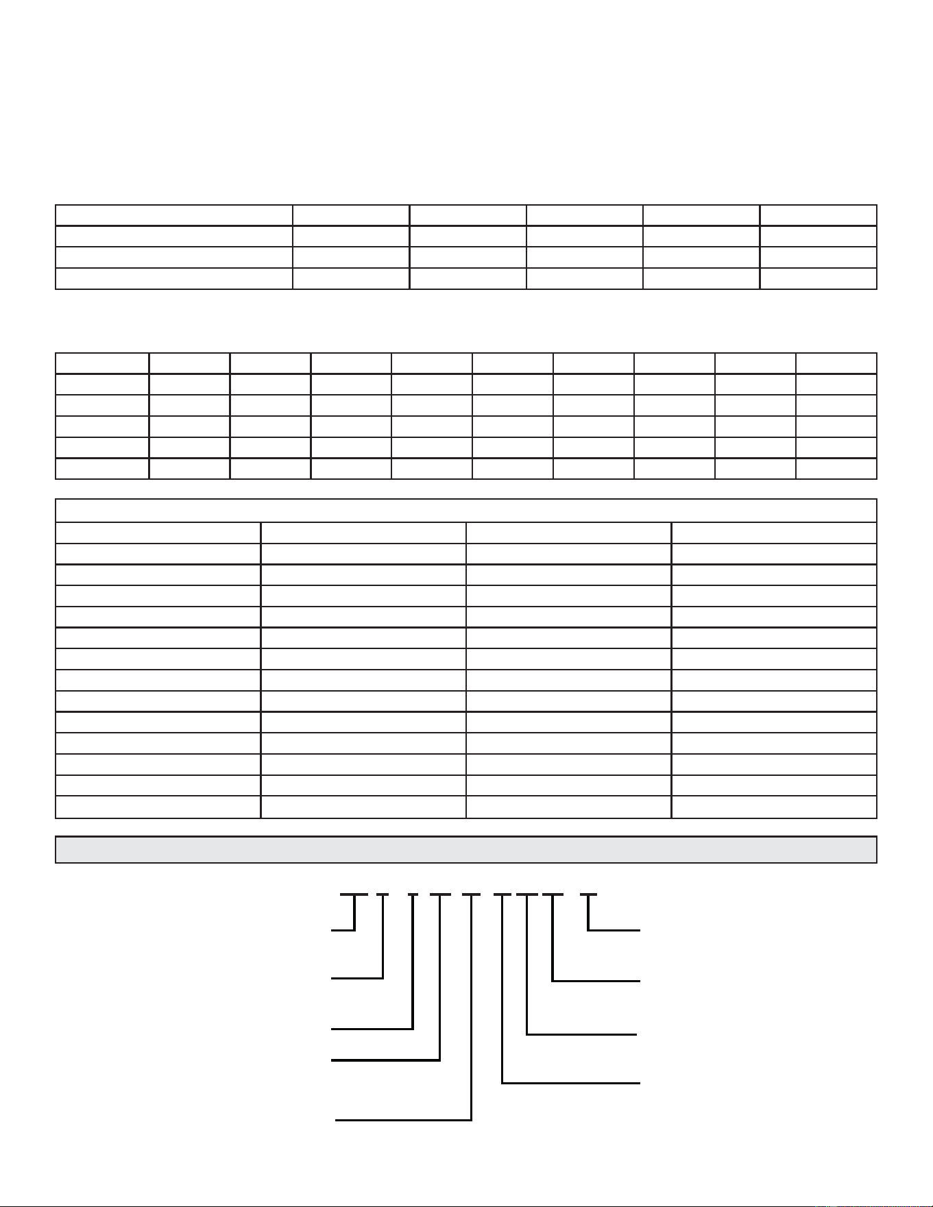
NOTE – R-454B is an A2L refrigerant. The system installation must meet the following parameters based upon total
refrigerant charge (line set included). TAmin (Total minimum conditioned area) is the minimum allowable conditioned area
based upon the total system charge at sea level. Values must be multiplied by altitude adjustment factor at installed altitude.
Qmin table refers to minimum airflow requirements during refrigerant leak mitigation by the refrigerant detection system,
based upon total system charge.
See tables below.
Charge (lb) 10 15 20 25 30
Charge (kg) 4.5 6.8 9.1 11.3 13.6
Minimum Conditioned Area (ft2) 149.9 224.9 299.9 374.8 449.8
Minimum Conditioned Area (m2) 13.9 20.9 27.9 34.8 41.8
TAmin Table
NOTE – Multiply values in TAmin table by the Altitude Adjustment Factors to correct TAmin based on installed altitude.
Altitude (m) 0 200 400 600 800 1000 1200 1400 1600
Altitude (ft) 0 660 1310 1970 2620 3280 3940 4590 5250
Adj. Factor 1 1 1 1 1.02 1.05 1.04 1.1 1.12
Altitude (m) 1600 1800 2000 2200 2400 2600 2800 3000 3200
Altitude (ft) 5250 5910 6560 7220 7870 8530 9190 9840 10500
Adj. Factor 1.12 1.15 1.18 1.21 1.25 1.28 1.32 1.36 1.4
Altitude Adjustment Factor
Qmin Table
Refrigerant Charge lb (kg) CFM Required Refrigerant Charge lb (kg) CFM Required
5 (-2.3) 135 18 (-8.1) 487
6 (-2.7) 162 19 (-8.6) 514
7 (-3.2) 189 20 (-9.1) 541
8 (-3.6) 216 21 (-9.5) 568
9 (-4.1) 244 22 (-10) 595
10 (-4.5) 271 23 (-10.4) 622
11 (-5) 298 24 (-10.9) 649
12 (-5.4) 325 25 (-11.3) 676
13 (-5.9) 352 26 (-11.7) 704
14 (-6.4) 379 27 (-12.2) 731
15 (-6.8) 406 28 (-12.7) 758
16 (-7.3) 433 29 (-13.2) 785
17 (-7.7) 460 30 (-13.6) 812
MAJOR / MINOR
REVISION
REFRIGERANT
5 - R454B
VOLTAGE
A - 208/230 1PH 60HZ
DESIGN VARIANT
S - SPECIFIED
BRAND
N-GE
PRODUCT
S - SPLIT
SEER2
APPLICATION
A - AIR CONDITIONER
COOLING CAPACITY
(1000BTU/HR)
18, 24, 30, 36, 42, 48, 60
N S A – XX
XX
16
16
A 24
24
S 5
Model Number Identification
49-5000962 Rev. 0 7
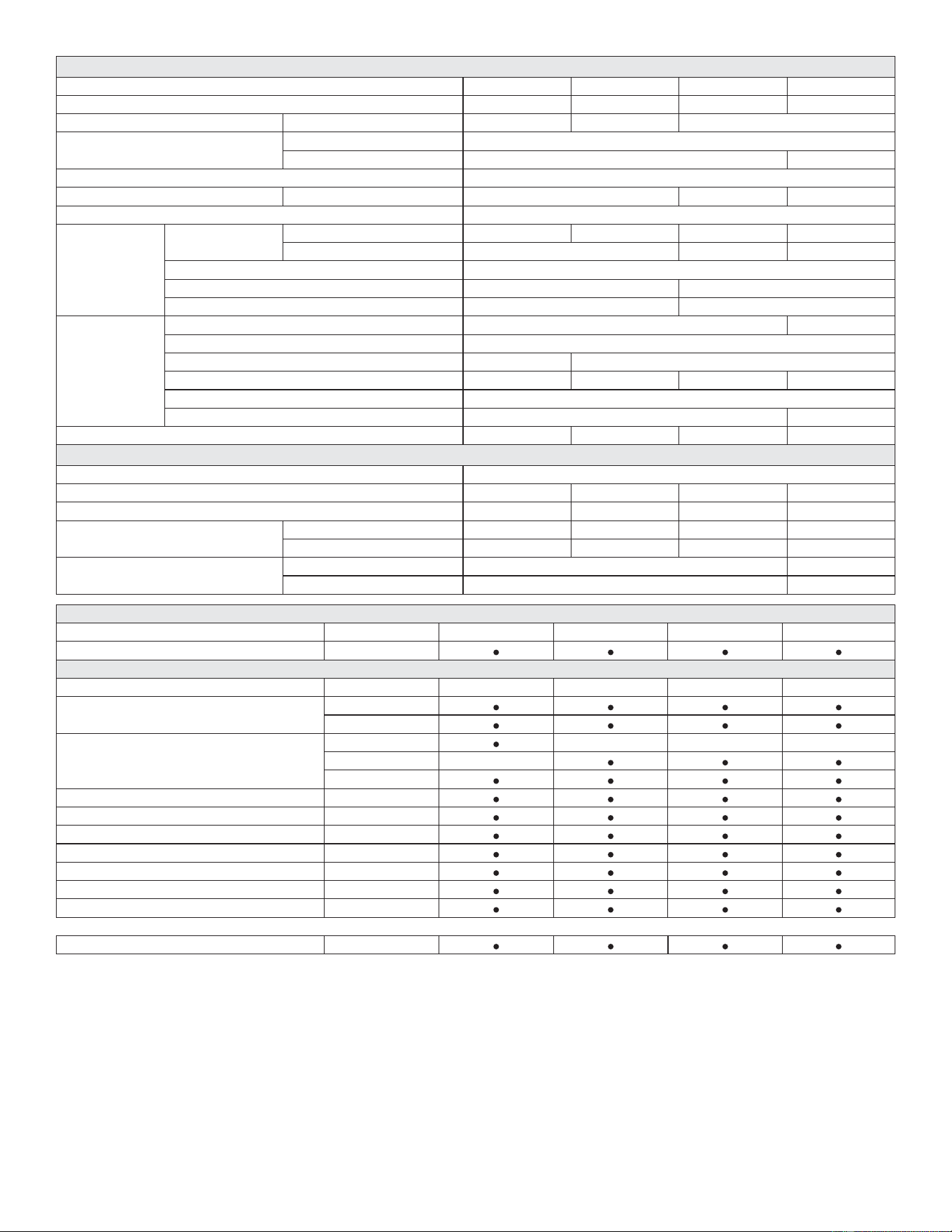
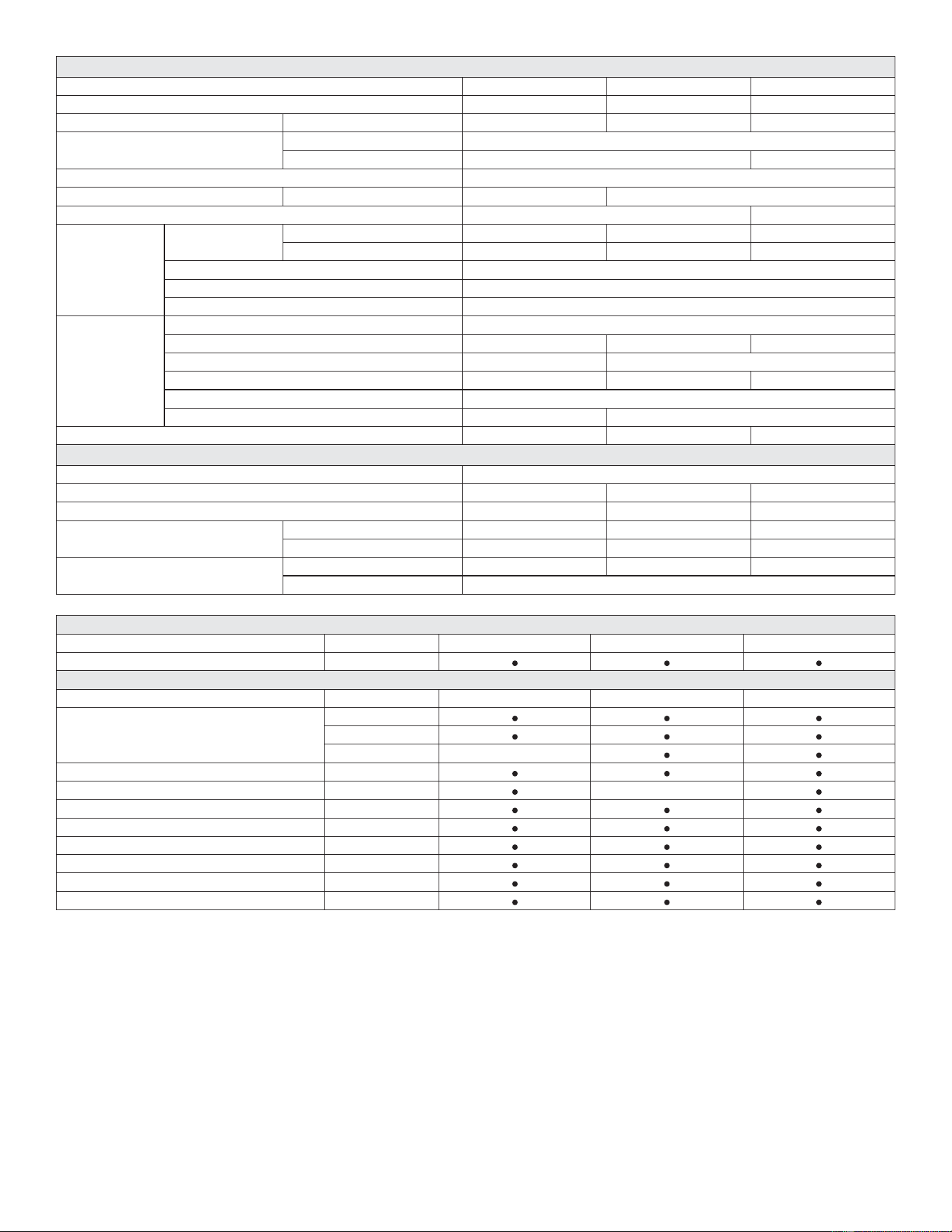
SPECIFICATIONS
Size 018 024 030 036
Nominal Tonnage 1.522.53
Sound Rating Number dBA 73 75 76
Connections (Sweat)
Liquid line (OD) - in. 3/8
Suction line (OD) - in. 3/4 7/8
Compressor Type 1-Stage Scroll
Refrigerant Type ¹ R-454B charge furnished 4 lbs. 14 oz. 5 lbs. 10 oz. 6 lbs. 13 oz.
Indoor Unit Expansion Valve (TXV) 26Z70
Outdoor Coil
Net face area - ft.²
Outer Coil 16.33 21.00 16.33 21.00
Inner Coil --- 15.75 20.25
Tube diameter - in. 5/16
Rows 1 2
Fins - in 26 22
Outdoor Fan
HP 1/8 1/6
Diameter - in. 22
Blades 2 3
Cfm 2610 2990 2820 3040
Rpm 825
Watts 160 190
Shipping Data - lbs. 155 170 180 200
ELECTRICAL DATA
Line voltage data (Volts-Phase-Hz) 208/230-1-60
² Maximum overcurrent protection (MOCP) amps (unit) 15 20 25 30
³ Minimum circuit ampacity (MCA) (unit) 11.2 13.6 16.6 21.8
Compressor
Rated load amps 8.3 10.3 12.7 16.7
Locked rotor amps 1.65 60.2 75.6 93.5
Fan Motor
Full load amps 0.74 1.0
Locked rotor amps 1.65 1.9
NOTE - Extremes of operating range are plus 10% and minus 5% of line voltage.
¹ Refrigerant charge is sufficient for 15 ft. length of refrigerant lines. For longer line set requirements see the Installation Instructions for information about line set length and additional refrigerant charge
required.
² HACR type breaker or fuse.
³ Refer to National or Canadian Electrical Code manual to determine wire, fuse and disconnect size requirements.
&UDQNFDVH+HDWHUDQG)UHH]HVWDWDUHUHFRPPHQGHGZLWK/RZ$PELHQW.LW
OPTIONAL CONTROLS - ORDER SEPARATELY
Accessory Part No. 018 024 030 036
Remote Outdoor Temperature Sensor X2658
OPTIONAL ACCESSORIES - ORDER SEPARATELY
Accessory Part No. 018 024 030 036
Compressor Crankcase Heater
Copeland 27V63
LG 27U16
Compressor Hard Start Kit
Copeland 63W22
Copeland 10J42
LG 10J42
&RPSUHVVRU/RZ$PELHQW&XW2ႇ6ZLWFK 45F08
Compressor Sound Cover 18J42
&RPSUHVVRU7LPHG2ႇ&RQWURO 47J27
Freezestat - 3/8 in. 93G35
,QGRRU%ORZHU2ႇ'HOD\5HOD\ 58M81
Loss of Charge Switch Kit 84M23
/RZ$PELHQW.LW)DQ&\FOLQJ 34M72
8QLW6WDQG2ႇ.LW 94J45
8 49-5000962 Rev. 0
SPECIFICATIONS
Size 042 048 060
Nominal Tonnage 3.5 4 5
Sound Rating Number dBA767880
Connections (Sweat)
Liquid line (OD) - in. 3/8
Suction line (OD) - in. 7/8 1-1/8
Compressor Type 1-Stage Scroll
Refrigerant Type ¹ R-454B charge furnished 7 lbs. 2 oz. 8 lbs. 14 oz.
Indoor Unit Expansion Valve (TXV) 26Z71 26Z72
Outdoor Coil
Net face area - ft.²
Outer coil 22.17 24.93 29.09
Inner coil 21.33 24.13 28.16
Tube diameter - in. 5/16
Rows 2
Fins - in 22
Outdoor Fan
HP 1/4
Diameter - in. 26 22 26
Blades 3 4
Cfm 4060 3700 4180
Rpm 825
Watts 260 290
Shipping Data - lbs. 225 235 260
ELECTRICAL DATA
Line voltage data (Volts-Phase-Hz) 208/230-1-60
² Maximum overcurrent protection (MOCP) amps (unit) 35 45 50
³ Minimum circuit ampacity (MCA) (unit) 23.2 29.7 31.2
Compressor
Rated load amps 17.3 22.4 23.7
Locked rotor amps 123 126 157
Fan Motor
Full load amps 1.56 1.7 1.56
Locked rotor amps 3.2
NOTE - Extremes of operating range are plus 10% and minus 5% of line voltage.
¹ Refrigerant charge is sufficient for 15 ft. length of refrigerant lines. For longer line set requirements see the Installation Instructions for information about line set length and additional refrigerant charge
required.
² HACR type breaker or fuse.
³ Refer to National or Canadian Electrical Code manual to determine wire, fuse and disconnect size requirements.
&UDQNFDVH+HDWHUDQG)UHH]HVWDWDUHUHFRPPHQGHGZLWK/RZ$PELHQW.LW
OPTIONAL CONTROLS - ORDER SEPARATELY
Accessory Part No. 042 048 060
Remote Outdoor Temperature Sensor X2658
OPTIONAL ACCESSORIES - ORDER SEPARATELY
Accessory Part No. 042 048 060
Compressor Hard Start Kit
Copeland 10J42
LG 10J42
LG 88M91
&RPSUHVVRU/RZ$PELHQW&XW2ႇ6ZLWFK 48F08
Compressor Sound Cover 18J42
&RPSUHVVRU7LPHG2ႇ&RQWURO 47J27
Freezestat - 3/8 in. 93G35
,QGRRU%ORZHU2ႇ'HOD\5HOD\ 58M81
Loss of Charge Switch Kit 84M23
/RZ$PELHQW.LW)DQ&\FOLQJ 34M72
8QLW6WDQG2ႇ.LW 94J45
49-5000962 Rev. 0 9
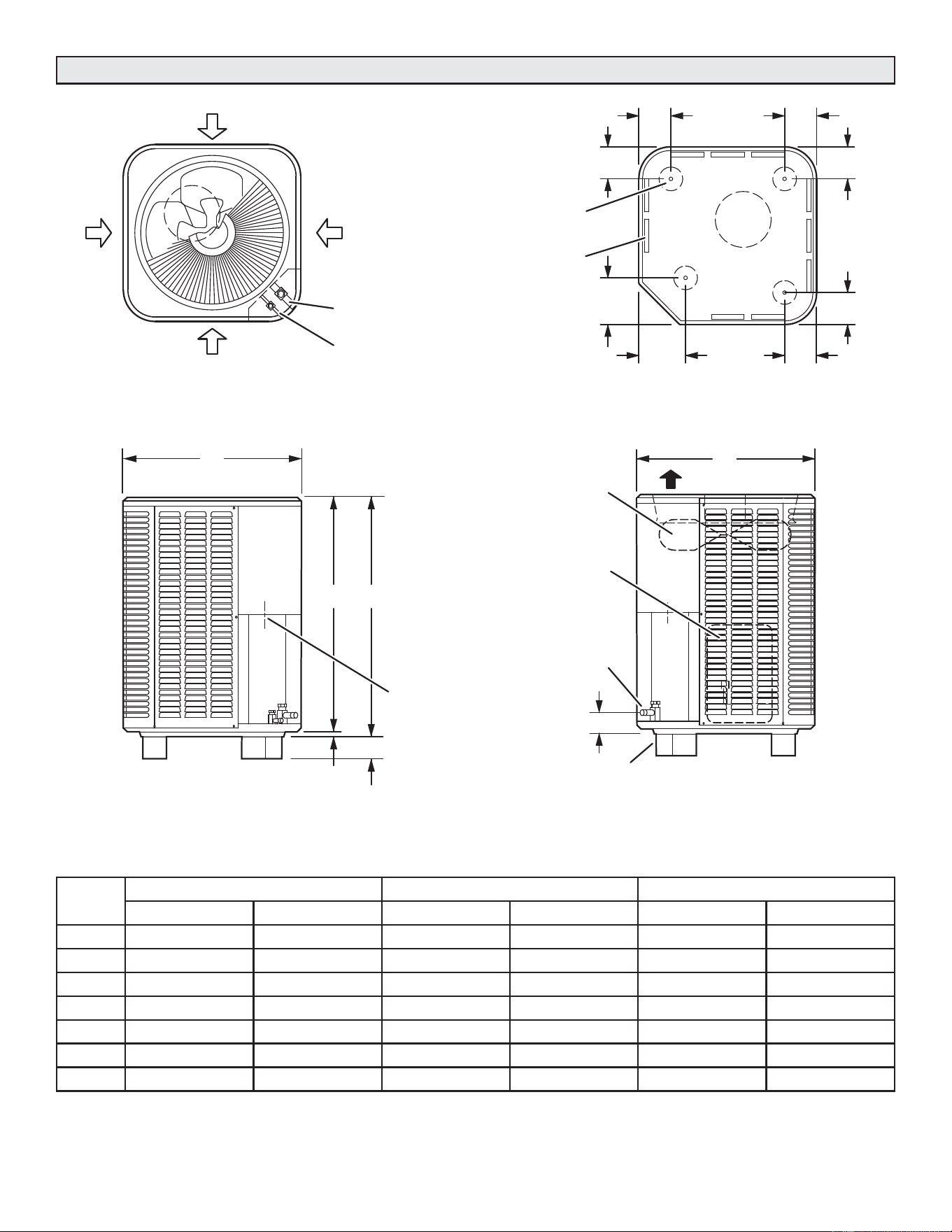
Unit Dimensions – Inches (mm)
SUCTION AND
C
SIDE VIEW
DISCHARGE AIR
SIDE VIEW
A
B
A
LIQUID LINE
CONNECTION
OUTDOOR
COIL FAN
COMPRESSOR
OPTIONAL UNIT
STANDOFF KIT (4)
(FIELD INSTALLED)
4-3/8
INLET
AIR
INLET
AIR
TOP VIEW
INLET AIR
INLET AIR
SUCTION LINE
CONNECTION
LIQUID LINE
CONNECTION
6-3/8
(162)
TOP VIEW BASE SECTION
COMPRESSOR
COIL DRAIN OUTLETS
(Around perimeter of base)
OPTIONAL UNIT
STAND-OFF KIT (4)
(Field Installed)
(111)
4-3/8
4-3/8
4-3/8
4-3/8
6-3/8
(162)
(111)
(111)
(111
()111)
4-3/8
(111)
2 (51)
3/4 (19)
2-3/4 (70)
ELECTRICAL
INLETS
Size A B C
In. mm in. mm in. mm
018 28-1/4 718 29-1/4 743 28-1/2 724
024 28-1/4 718 37-1/4 946 36-1/2 927
030 28-1/4 718 29-1/4 743 28-1/2 724
036 28-1/4 718 37-1/4 946 36-1/2 927
042 32-1/4 819 33-1/4 845 32-1/2 826
048 28-1/4 718 43-1/4 1099 42-1/2 1080
060 32-1/4 819 43-1/4 1099 42-1/2 1080
10 49-5000962 Rev. 0
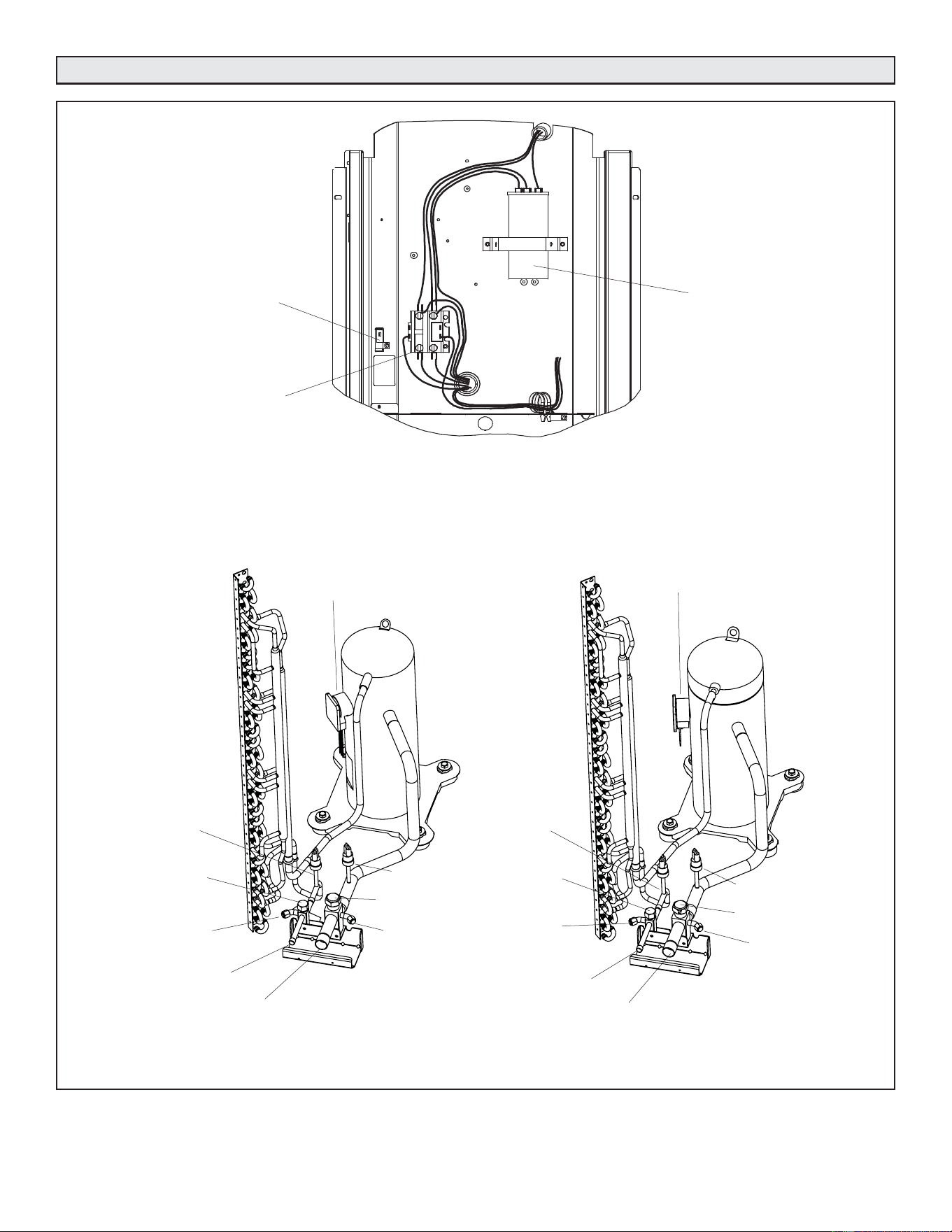
Typical Unit Parts Arrangement
FIELD CONNECTION
FOR LIQUID LINE SET
LIQUID LINE
SERVICE VALVE
LIQUID LINE
SERVICE VALVE
PORT
SUCTION LINE
SERVICE VALVE
PORT
SUCTION LINE
SERVICE VALVE
FIELD CONNECTION
FOR SUCTION LINE
HIGH PRESSURE
SWITCH (S4)
COMPRESSOR
HARNESS
GROUND LUG
CONTACTOR 1-POLE (K1-1)
CAPACITOR (C12)
CONTROL BOX
TYPICAL PLUMBING
(COPELAND COMPRESSOR)
TYPICAL PLUMBING
(LG COMPRESSOR)
HIGH PRESSURE
SWITCH (S4)
FIELD CONNECTION
FOR LIQUID LINE SET
LIQUID LINE
SERVICE VALVE
LIQUID LINE
SERVICE VALVE
PORT
FIELD CONNECTION
FOR SUCTION LINE
SUCTION LINE
SERVICE VALVE
SUCTION LINE
SERVICE VALVE
PORT
COMPRESSOR
HARNESS
LOW PRESSURE
SWITCH
LOW PRESSURE
SWITCH
FIGURE 1.
49-5000962 Rev. 0 11
Component Specifications
Refrigerant Metering Device – Indoor Coil
Operating Gauge Set and Service Valves
TABLE 1. Service Valve Sizes and Refrigerant Line Set Recommendations
Model
Service Valve Sizes Recommended Line Set
Liquid Line Suction Line Liquid Line Suction Line
-018, -024, -030
3/8 in. (10 mm)
3/4 in. (19 mm)
3/8 in. (10 mm)
3/4 in. (19 mm)
-036, -042, -048 7/8 in. (22 mm) 7/8 in. (22 mm)
-059, -060 1-1/8 in. (22 mm) 1-1/8 in. (22 mm)
NOTE — Some applications may require a field provided 7/8” to 1-1/8” adapter
EXPANSION VALVE (TXV) METERING
This unit is compatible with systems that use an expansion
valve. Refer to any of the publications listed below to obtain
the required catalog number for a specific expansion valve.
• NS16A Product Specifications
TORQUE REQUIREMENTS
When servicing or repairing heating, ventilating, and
air conditioning components, ensure the fasteners are
appropriately tightened. TABLE 2 lists torque values for
fasteners.
USING MANIFOLD GAUGE SET
When checking the system charge, only use a manifold
gauge set that features low loss anti-blow back fittings.
Manifold gauge set used with R-454B refrigerant systems
must be capable of handling the higher system operating
pressures. The gauges should be rated for use with
pressures of 0 - 800 psig on the high side and a low side of
30” vacuum to 250 psig with dampened speed to 500 psi.
Gauge hoses must be rated for use at up to 800 psig of
pressure with a 4000 psig burst rating.
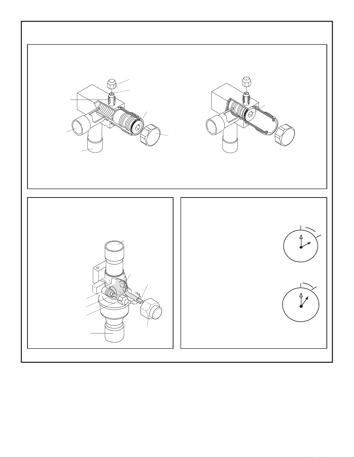
OPERATING SERVICE VALVES
The liquid and vapor line service valves are used for
removing refrigerant, flushing, leak testing, evacuating,
checking charge and charging. Each valve is equipped
with a service port which has a factory-installed valve stem.
FIGURE 2 provides information on access and operation of
both angle and ball service valves.
The Clean Air Act of 1990 bans the intentional venting of
refrigerant (CFCs, HCFCs and HFCs) as of July 1, 1992.
Approved methods of recovery, recycling or reclaiming
must be followed. Fines and/or incarceration may be
levied for noncompliance.
IMPORTANT
2QO\ XVH $OOHQ ZUHQFKHV RI VXႈFLHQW KDUGQHVV 5F
- Rockwell Harness Scale minimum). Fully insert the
wrench into the valve stem recess.
Service valve stems are factory-torqued (from 9 ft-lbs
for small valves, to 25 ft-lbs for large valves) to prevent
refrigerant loss during shipping and handling. Using an
Allen wrench rated at less than 50Rc risks rounding
RU EUHDNLQJ Rႇ WKH ZUHQFK RU VWULSSLQJ WKH YDOYH VWHP
recess.
IMPORTANT
To prevent stripping of the various caps used, the
DSSURSULDWHO\ VL]HG ZUHQFK VKRXOG EH XVHG DQG ¿WWHG
snugly over the cap before tightening.
IMPORTANT
TABLE 2. Torque Requirements
Parts Recommended Torque
Service valve cap 8 ft.- lb. 11 NM
Sheet metal screws 16 ft.- lb. 2 NM
Machine screws #10 28 ft.- lb. 3 NM
Compressor bolts 90 in.- lb. 10 NM
Gauge port seal cap 8 ft.- lb. 11 NM
12 49-5000962 Rev. 0
SERVICE VALVES ANGLE AND BALL
FIGURE 2. Angle and Ball Service Valves
Operating Angle Type Service Valve:
1. Remove stem cap with an appropriately sized wrench.
2. Use a service wrench with a hex-head extension (3/16” for liquid line valve sizes and 5/16” for vapor line valve sizes) to back the stem out
counterclockwise as far as it will go.
Operating Ball Type Service Valve:
1. Remove stem cap with an appropriately sized wrench.
2. Use an appropriately sized wrenched to open.
– To open valve, roate stem counterclockwise 90°.
– To close valve, rotate stem clockwise 90°.
To Access Service Port:
1. Remove service port cap with an appropriately sized wrench.
2. Connect gauge set to service port.
3. When testing is completed, replace service
port cap and tighten as follows:
• With torque wrench: Finger tighten and
torque cap per Table 2.
• Without torque wrench: Finger tighten and
use an appropriately sized wrench to turn an
additional 1/6 turn clockwise.
Reinstall Stem Cap:
Stem cap protects the valve stem from
damage and serves as the primary seal.
Replace the stem cap and tighten as follows:
• With Torque Wrench: Finger tighten and
then torque cap per Table 2.
• Without Torque Wrench: Finger tighten
and use an appropriately sized wrench to
turn an additional 1/12 turn clockwise.
ANGLE-TYPE SERVICE VALVE
(BACK-SEATED OPENED)
When service valve is OPEN, the service port
is open to linE set, indoor and outdoor unit.
ANGLE-TYPE SERVICE VALVE
(FRONT-SEATED CLOSED)
When service valve is CLOSED, the service
port is open to the linE set and indoor unit.
Service Port Core
Service Port Core
To Outdoor Unit
Stem Cap
Service Port Cap
To Indoor Unit
(Valve Stem Shown Open)
Insert Hex Wrench Here
(Valve Stem Shown Closed)
Insert Hex Wrench Here
1
2
3
4
5
6
7
8
9
10
11
12
1/6 TURN
Ball (Shown
Closed)
Service Port Core
To Indoor Unit
To Outdoor Unit
To OPEN, rotate stem
counterclockwise 90°.
To CLOSE, rotate stem
clockwise 90°.
Service Port
Service Port Cap
Stem Cap
Valve
Stem
1
2
3
4
5
6
7
8
9
10
11
12
1/12 TURN
NOTE — A label with specific torque requirements may be affixed to the stem cap. If the label is present, use the specified torque.
49-5000962 Rev. 0 13
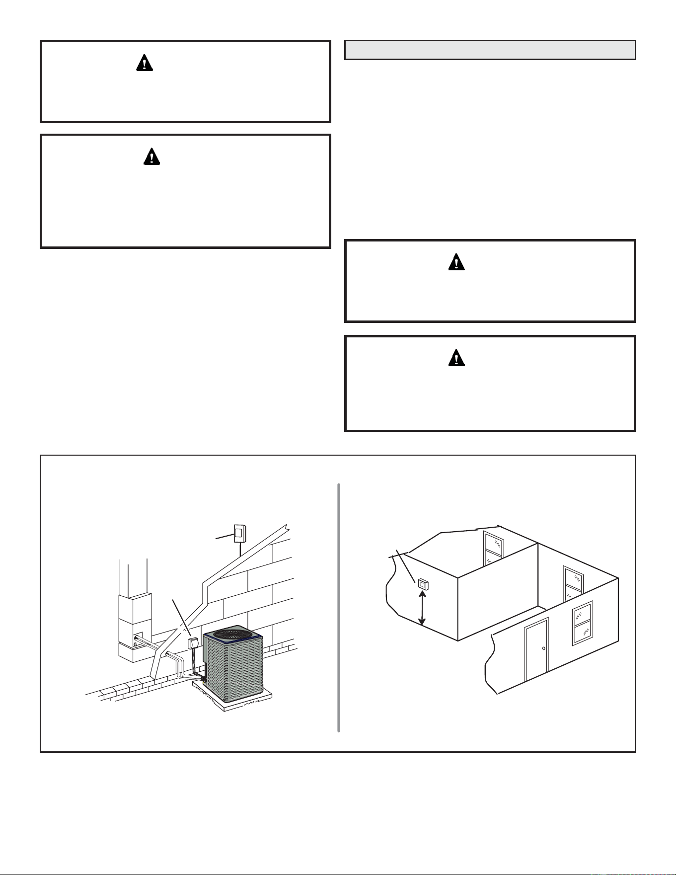
Installation
Unit Placement
See Unit Dimensions on Page 9 for sizing mounting slab,
platforms or supports.
POSITIONING CONSIDERATIONS
Consider the following when positioning the unit:
• Some localities are adopting sound ordinances based on
the unit’s sound level registered from the adjacent property,
not from the installation property. Install the unit as far as
possible from the property line.
• When possible, do not install the unit directly outside a
window. Glass has a very high level of sound transmission.
For proper placement of unit in relation to a window see the
provided illustration in FIGURE 4, detail A.
PLACING UNIT ON SLAB
When installing unit at grade level, the top of the slab
should be high enough above grade so that water from
higher ground will not collect around the unit.
The slab should have a slope tolerance as described in
FIGURE 4, detail B.
NOTE – If necessary for stability, anchor unit to slab.
ROOF MOUNTING
Install the unit a minimum of 6 inches (152 mm) above the
roof surface to avoid ice build-up around the unit. Locate the
unit above a load bearing wall or area of the roof that can
adequately support the unit. Consult local codes for rooftop
applications. If unit coil cannot be mounted away from
prevailing winter winds, a wind barrier should be constructed.
Size barrier at least the same height and width as outdoor
unit. Mount barrier 24 inches (610 mm) from the sides of the
unit in the direction of prevailing winds.
In order to avoid injury, take proper precaution when
lifting heavy objects.
CAUTION
Roof Damage!
This system contains both refrigerant and oil. Some
UXEEHU URR¿QJ PDWHULDO PD\ DEVRUE RLO FDXVLQJ WKH
UXEEHUWRVZHOO%XEEOHVLQWKHUXEEHUURR¿QJPDWHULDOFDQ
cause leaks. Protect the roof surface to avoid exposure to
refrigerant and oil during service and installation. Failure
to follow this notice could result in damage to roof surface.
NOTICE
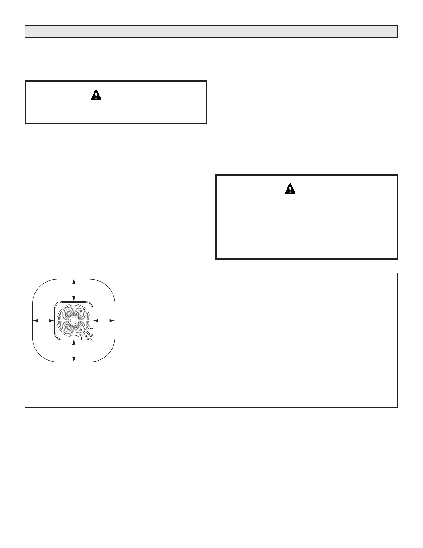
NOTES -
• Service clearance of 30 in. (762 mm) must be maintained on one of the sides
adjacent to the control box.
• Clearance to one of the other three sides must be 36 in. (914 mm).
• Clearance to one of the remaining two sides may be 12 in. (305 mm) and the final
side may be 6 in. (152 mm).
• A clearance of 24 in. must be maintained between two units.
• 48 in. (1219 mm) clearance required on top of unit.
NOTICE: Specific applications may require adjustment of the listed installation clearances to provide protection for
the unit from physical damage or to avoid conditions which limit operating efficiency. (Example: Clearances may have
to be increased to prevent snow or ice from falling on the top of the unit. Additional clearances may also be required
to prevent air recirculation when the unit is installed under a deck or in another tight space.)
See
NOTES
See NOTES
See NOTES
See
NOTES
Control
Box
FIGURE 3. Installation Clearances
14 49-5000962 Rev. 0
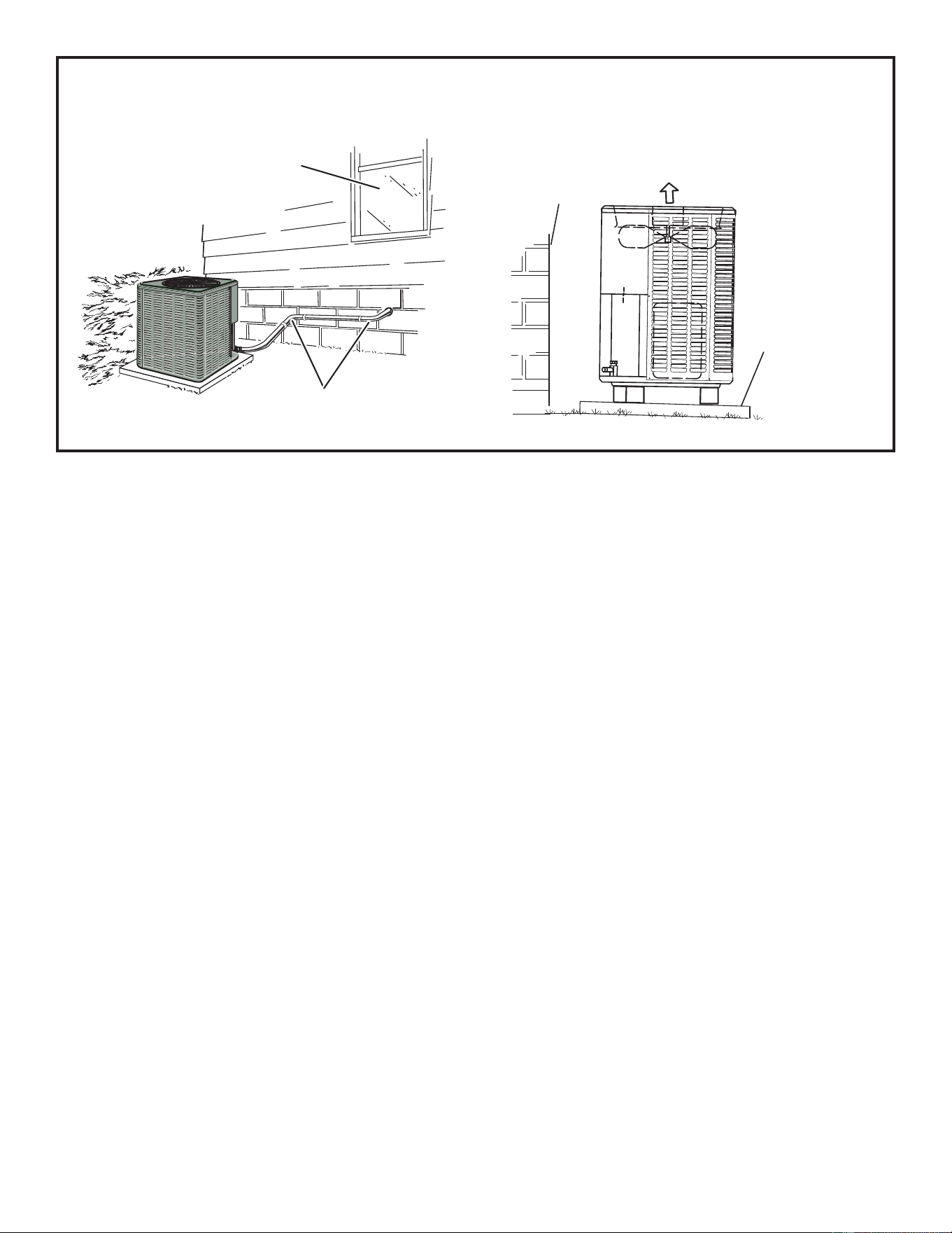
FIGURE 4. Placement and Slab Mounting
DETAIL A DETAIL B
Install unit level or, if on a slope, maintain slope tolerance
of 2 degrees (or 2 inches per 5 feet [50 mm per 1.5 m])
away from building structure.
Ground Level
Mounting Slab
Building
Structure
Discharge Air
Install unit away
from windows
Two 90º elbows installed in line set
will reduce line set vibration.
49-5000962 Rev. 0 15
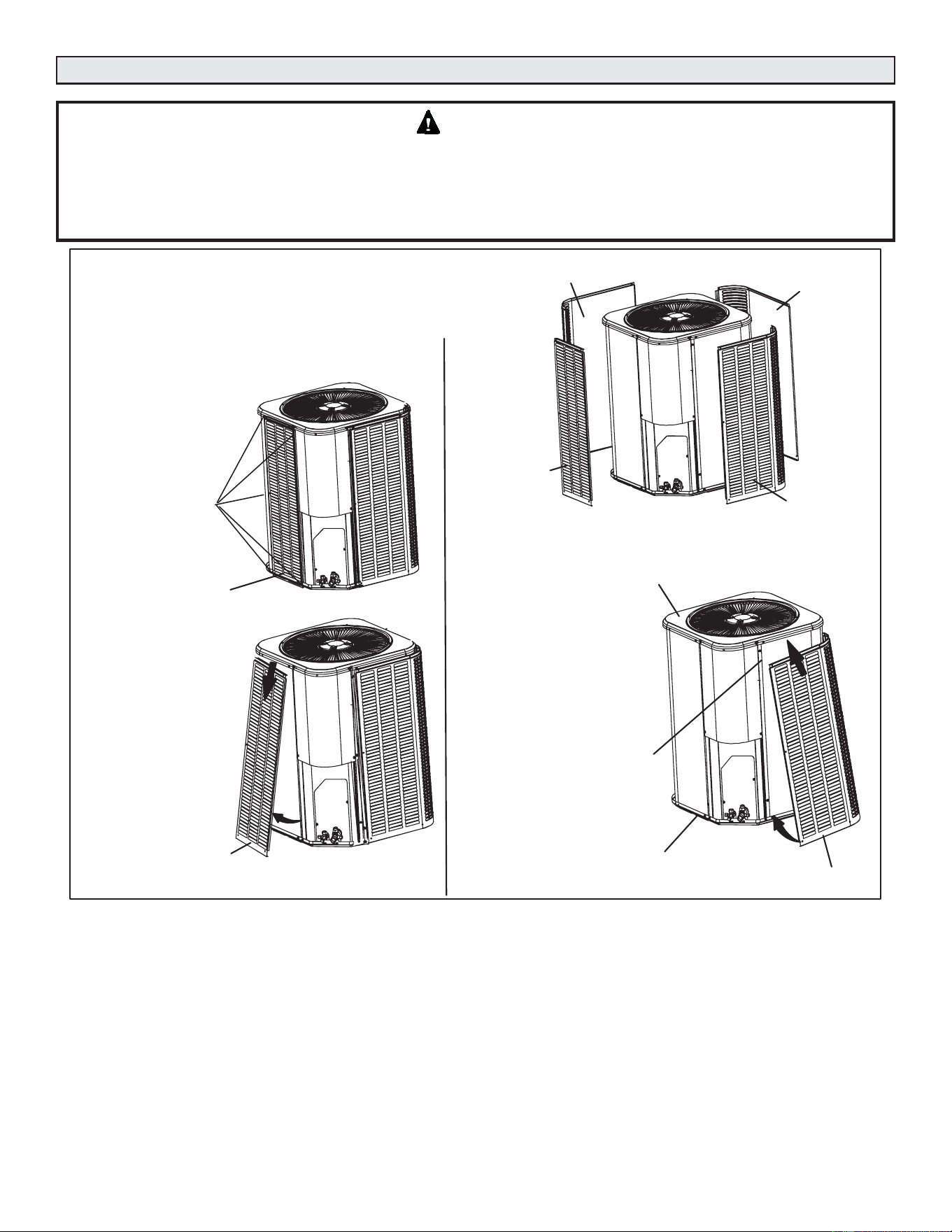
Removing and Installing Louvered Panels
To prevent personal injury, or damage to panels, unit or structure, be sure to observe the following:
While installing or servicing this unit, carefully stow all removed panels out of the way, so that the panels will not cause
injury to personnel, nor cause damage to objects or structures nearby, nor will the panels be subjected to damage (e.g.,
being bent or scratched). While handling or stowing the panels, consider any weather conditions, especially windy
conditions, that may cause panels to be blown around and battered.
WARNING
Line Set Joints – Furnace Application
Evaporator primary line set joints in all applications shall
have a line set joint sleeve.
Evaporator primary line sets should not have additional
joints not covered by line set joint sleeve.
If additional joints are present, the system installation
shall comply with one of the options below:
Option 1 - Furnace is installed as a direct vent appliance;
Option 2 - Furnace/Evaporator installation is in a space
greater than the minimum conditioned area (Amin);
Option 3 - Furnace/Evaporator installation is connected to
a space greater than the minimum conditioned area (Amin)
through an opening of at least 15 in² (4-inch diameter hole
equivalent) located below the level of the furnace burners;
Option 4 - Have a second refrigerant detection sensor
installed below the level of the burners (see Secondary
Sensor Installation section).
Multiple Systems Installed in Same Space
For any A2L refrigerant system with additional joints not
covered by line set joint sleeves, each system in the same
space must have refrigerant detection sensor installed below
the level of the burners (see Secondary Sensor Installation
section). If all the systems in the same space are installed
with direct vent application, then additional refrigerant
detection sensor is not needed
FIGURE 5. Removing and Installing Panels
WARNING
PANEL A
PANEL B
PANEL C
PANEL D
When removing the unit panels. Remove panel A first, then B, C and
finally D. When reinstalling panels, reverse that order starting with panel
D, C, B and finally A.
REMOVAL
Repeat steps 1, 2 and 3
to remove panels B, C
and D.
STEP 1
Starting with panel D. Insert
panel unit unit top cap lip and
lift slightly to clear side lip of
panel from base.
PANEL A
PANEL A
STEP 2
INSTALLATION
Repeat steps 1 and 2 when
installing panels C, B and A.
To remove panel,
remove mounting
screws securing panel
to the unit.
Slightly lift panel A in order
to clear side lips of panel
from base of unit.
STEP 3
Tilt panel out slightly and
pull downward to remove.
STEP 1
STEP 2
Move panel in towards unit. Align
left / right side lips of panel with
groove inserts along left / right
side of unit.
PANEL D
TOP CAP
BASE
SIDE
GROOVE
STEP 3
Secure panel with mounting screws.
16 49-5000962 Rev. 0
Secondary Sensor Installation
If secondary refrigerant sensor is required, it shall be
mounted as follows:
Upflow Applications: Mounted on an unused side furnace
return air connection at least 9 inches above the floor and
within 9 inches from front of furnace.
Downflow Applications: Mounted on one side of the
evaporator coil 9 inches above the floor and within 9 inches
from front of coil.
Horizontal Applications: Mounted on the bottom side
return furnace air connection within 9 inches of both the
blower deck and front of furnace.
Connect the refrigerant sensor to the second sensor input on
the RDS Control. Refer to the instructions provided with the
sensor or the RDS controller to enable the second sensor.
New or Replacement Line Set
This section provides information on new installation or
replacement of existing line set. If a new or replacement line
set is not required, then proceed to Brazing Connections on
Page 19.
Field refrigerant piping consists of liquid and suction lines
from the outdoor unit (braze connections) to the indoor
unit coil (flare or braze connections). Use readily available
(braze, non-flare) series line set, or use field-fabricated
refrigerant lines as listed in TABLE 3.
To obtain the correct information from GE Appliances, be
sure to communicate the following points:
• Model (NS16A) and size of unit (e.g. -060).
• Line set diameters for the unit being installed as listed in
TABLE 1 and total length of installation.
• Number of elbows and if there is a rise or drop of the piping.
If refrigerant lines are routed through a wall, seal and isolate
the opening so vibration is not transmitted to the building.
Pay close attention to line set isolation during installation
of any HVAC system. When properly isolated from building
structures (walls, ceilings. floors), the refrigerant lines will
not create unnecessary vibration and subsequent sounds.
The compressor is charged with sufficient Polyol ester oil
for line set lengths up to 50 feet. Recommend adding oil
to system based on the amount of refrigerant charge in the
system. No need to add oil in a system with 20 pounds of
refrigerant or less. For systems over 20 pounds - add one
ounce for every five pounds of refrigerant over 20 pounds.
Recommended topping-off POE oils are Mobil EAL ARCTIC
&&RU,&,(0.$5$7(5/0$)
REFRIGERANT LINE SET – INCHES (MM)
Model
Valve Field Connections Recommended Line Set
Liquid Line Vapor Line Liquid Line Vapor Line
-036
3/8 in.
(10 mm)
7/8 in.
(22 mm)
3/8 in.
(10 mm)
7/8 in.
(22 mm)
-042
-048
-060
3/8 in.
(10 mm)
1-1/8 in.
(28 mm)
3/8 in.
(10 mm)
1-1/8 in.
(28 mm)
NOTE - Some applications may require a field-provided 7/8” to 1-1/8”
adapter.
NOTE - When installing refrigerant lines longer than 50
feet, refer to the Refrigerant Piping Design and Fabrication
Guidelines manual available on GEApliances.com,
or contact the Technical Support Department Product
Application group for assistance.
Refrigerant can be harmful if it is inhaled. Refrigerant
must be used and recovered responsibly. Failure to follow
this warning may result in personal injury or death.
WARNING
When using a high pressure gas such as
nitrogen to pressurize a refrigeration or air
conditioning system, use a regulator that can
control the pressure down to 1 or 2 psig (6.9
to 13.8 kPa).
WARNING
Fire, Explosion and Personal Safety hazard.
Failure to follow this warning could result in
damage, personal injury or death.
Never use oxygen to pressurize or purge
refrigeration lines. Oxygen, when exposed
WRDVSDUNRURSHQÀDPHFDQFDXVH¿UHDQG
or an explosion, that could result in property
damage, personal injury or death.
WARNING
TABLE 3
49-5000962 Rev. 0 17
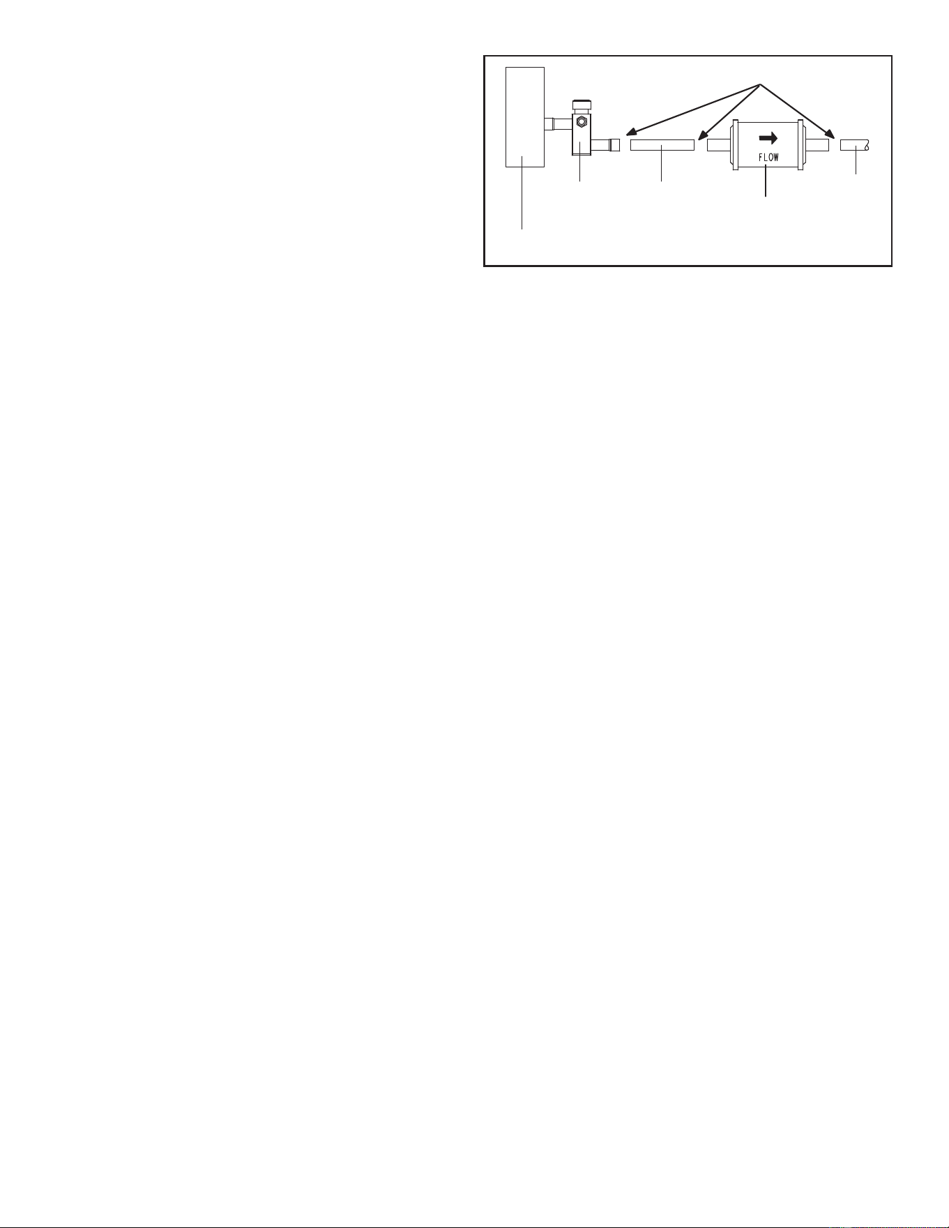
LIQUID LINE FILTER DRIER INSTALLATION
The provided filter drier must be field installed outdoors in
the liquid line between the units liquid line service valve
and before the liquid line enters the structure. It is not
recommended to install the liquid line filter drier indoors due
to additional braze joints required. This filter drier must be
installed to ensure a clean, moisture-free system. Failure to
install the filter drier will void the warranty. A replacement
filter drier is available from GE Appliances. See Brazing
Connections on Page 19 for special procedures on brazing
filter drier connections to the liquid line.
OUTDOOR
UNIT
LIQUID LINE
SERVICE VALVE
LIQUID LINE
FILTER DRIER
LINE
LIQUID
LINE
BRAZE CONNECTION POINTS
FIGURE 6. Typical Liquid Line Filter Drier Installation
18 49-5000962 Rev. 0
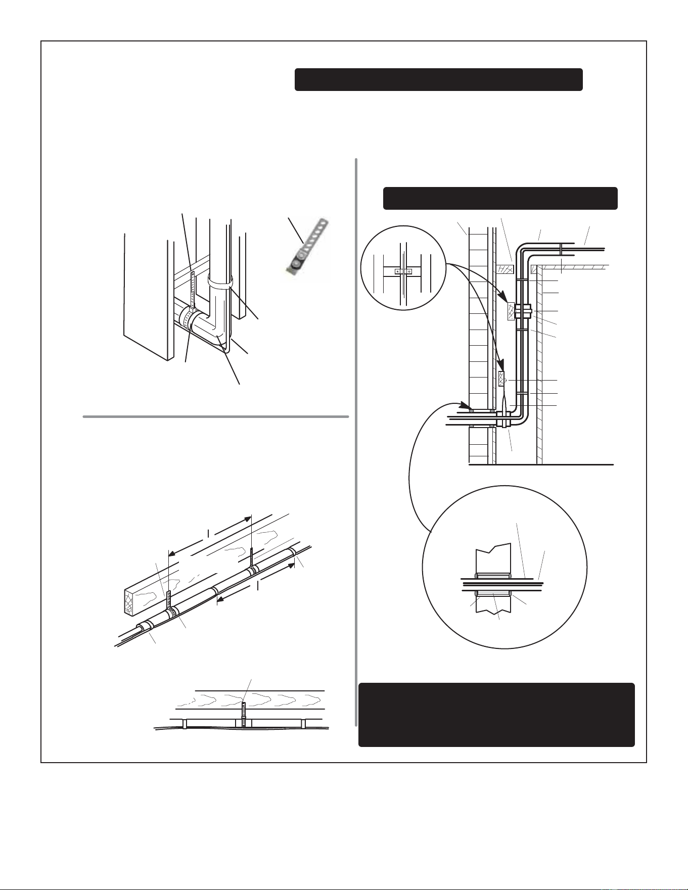
FIGURE 7. Line Set Installation
ANCHORED HEAVY NYLON
WIRE TIE OR AUTOMOTIVE
MUFFLER‐TYPE HANGER
STRAP LIQUID LINE TO
VAPOR LINE
WALL
STUD
LIQUID LINE
NON-CORROSIVE
METAL SLEEVE
VAPOR LINE - WRAPPED
IN ARMAFLEX
AUTOMOTIVE
MUFFLER‐TYPE HANGER
REFRIGERANT LINE SET — TRANSITION
FROM VERTICAL TO HORIZONTAL
Line Set Isolation — The following illustrations are
examples of proper refrigerant line set isolation:
STRAPPING
MATERIAL (AROUND
VAPOR LINE ONLY)
TAPE OR
WIRE TIE
WIRE TIE (AROUND
VAPOR LINE ONLY)
FLOOR JOIST OR
ROOF RAFTER
TAPE OR
WIRE TIE
To hang line set from joist or rafter, use either metal strapping material
or anchored heavy nylon wire ties.
8 FEET (2.43 METERS)
STRAP THE VAPOR LINE TO THE JOIST
OR RAFTER AT 8 FEET (2.43 METERS)
INTERVALS THEN STRAP THE LIQUID
LINE TO THE VAPOR LINE.
FLOOR JOIST OR
ROOF RAFTER
REFRIGERANT LINE SET — INSTALLING
HORIZONTAL RUNS
NOTE — Similar installation practices should be used if line set is
to be installed on exterior of outside wall.
PVC
PIPE
FIBERGLASS
INSULATION
CAULK
OUTSIDE
WALL
VAPOR LINE WRAPPED
WITH ARMAFLEX
LIQUID
LINE
OUTSIDE WALL
LIQUID LINE
VAPOR LINE
WOOD BLOCK
BETWEEN STUDS
STRAP
WOOD BLOCK
STRAP
SLEEVE
WIRE TIE
WIRE TIE
WIRE TIE
INSIDE WALL
REFRIGERANT LINE SET — INSTALLING
VERTICAL RUNS (NEW CONSTRUCTION SHOWN)
INSTALLATION
LINE SET
NOTE — Insulate liquid line when it is routed through areas where the
surrounding ambient temperature could become higher than the
temperature of the liquid line or when pressure drop is equal to or greater
than 20 psig.
NON-CORROSIVE
METAL SLEEVE
IMPORTANT — Refrigerant lines must not contact structure.
NON-CORROSIVE
METAL SLEEVE
8 FEET (2.43 METERS)
IMPORTANT — Refrigerant lines must not contact wall
WARNING — Polyol ester (POE) oils used with R-454B
refrigerant absorb moisture very quickly. It is very important that the
refrigerant system be kept closed as much as possible. DO NOT
remove line set caps or service valve stub caps until you are ready
to make connections.
49-5000962 Rev. 0 19
Brazing Connections
Use the procedures outlined in FIGURE 8 and FIGURE 9 for
brazing line set connections to service valves.
%UD]LQJ DOOR\V DQG ÀX[ FRQWDLQ PDWHULDOV ZKLFK DUH
hazardous to your health.
Avoid breathing vapors or fumes from brazing operations.
Perform operations only in well-ventilated areas.
Wear gloves and protective goggles or face shield to
protect against burns.
Wash hands with soap and water after handling brazing
DOOR\VDQGÀX[
CAUTION
If this unit is being matched with an approved line set, it
PXVWEHÀXVKHGSULRUWRLQVWDOODWLRQ7DNHFDUHWRHPSW\
all existing traps. Polyol ester (POE) oils are used in
GE Appliances units charged with R-454B refrigerant.
Residual mineral oil can act as an insulator, preventing
proper heat transfer. It can also clog the expansion device
and reduce system performance and capacity.
)DLOXUHWR SURSHUO\ ÀXVKWKHV\VWHP SHU WKLVLQVWUXFWLRQ
and the detailed Installation and Service Procedures
manual will void the warranty.
IMPORTANT
Allow braze joint to cool before removing the wet rag
from the service valve. Temperatures above 250ºF can
damage valve seals.
IMPORTANT
%UD]H)UHH ¿WWLQJV PXVW FRQIRUP ZLWK 8/ RU ,62
14903 (latest edition).
IMPORTANT
'DQJHU RI ¿UH %OHHGLQJ WKH UHIULJHUDQW
charge from only the high side may result
in pressurization of the low side shell and
suction tubing. Application of a brazing torch
to a pressurized system may result in ignition
of the refrigerant and oil mixture. Check the
high and low pressures before applying heat.
WARNING
Use silver alloy brazing rods with 5% minimum silver alloy
for copper-to-copper brazing. Use 45% minimum alloy for
copper-to-brass and copper-to-steel brazing.
IMPORTANT
20 49-5000962 Rev. 0
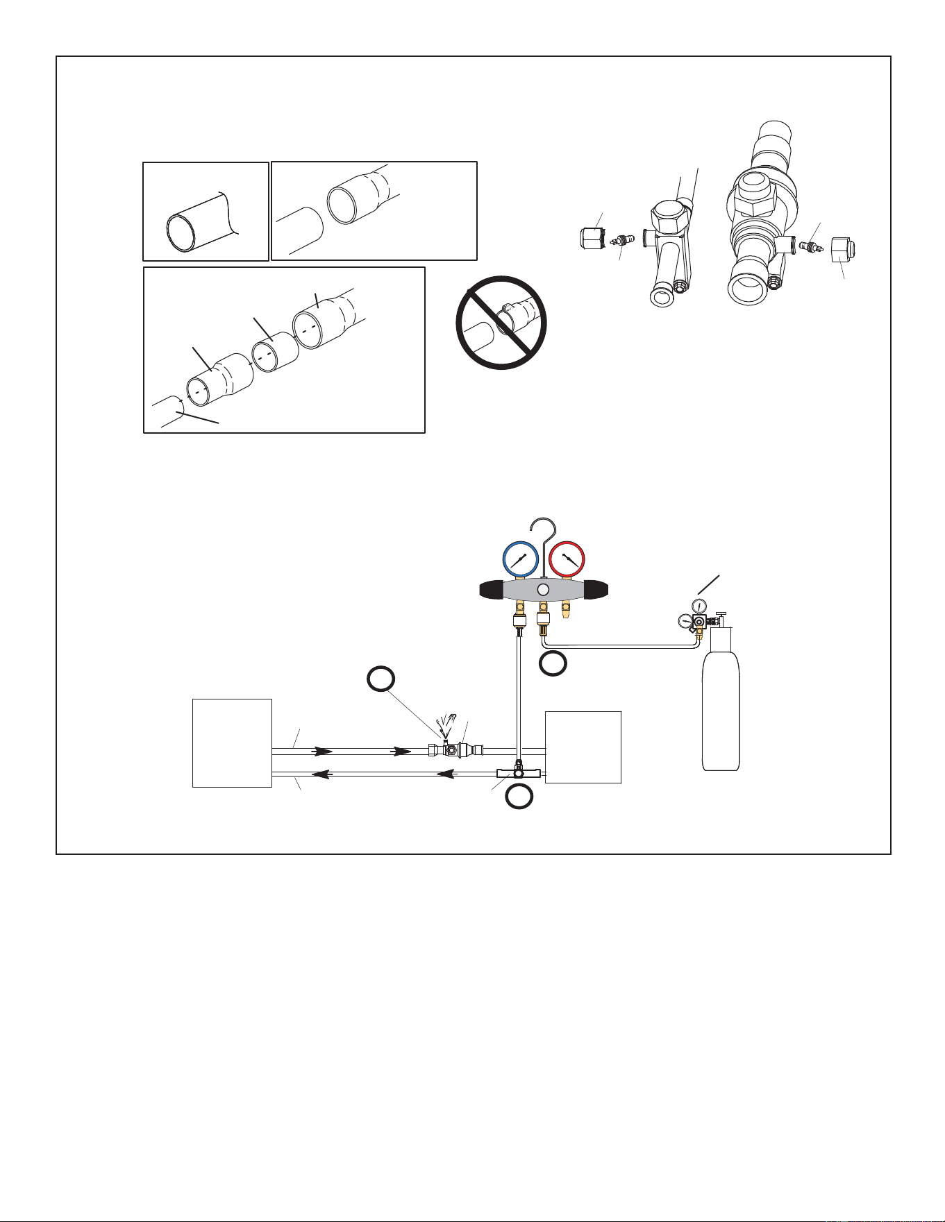
FIGURE 8. Brazing Procedures
ATTACH THE MANIFOLD GAUGE SET FOR BRAZING LIQUID AND SUCTION / VAPOR LINE SERVICE
VALVES
OUTDOOR
UNIT
LIQUID LINE
VAPOR LINE
LIQUID LINE SERVICE
VALVE
SUCTION /
VAPOR LINE
SERVICE
VALVE
ATTACH
GAUGES
INDOOR
UNIT
SUCTION / VAPOR SERVICE PORT MUST BE
OPEN TO ALLOW EXIT POINT FOR NITROGEN
A Connect gauge set low pressure side to
liquid line service valve (service port).
B Connect gauge set center port to bottle of
nitrogen with regulator.
C Remove core from valve in suction / vapor
line service port to allow nitrogen to escape.
NITROGEN
HIGHLOW
USE REGULATOR TO FLOW
NITROGEN AT 1 TO 2 PSIG.
B
A
C
WHEN BRAZING LINE SET TO
SERVICE VALVES, POINT FLAME
AWAY FROM SERVICE VALVE.
Flow regulated nitrogen (at 1 to 2 psig) through the low-side refrigeration gauge set into the liquid line service port valve, and out of the suction /
vapor line service port valve.
CUT AND DEBUR
CAP AND CORE REMOVAL
Cut ends of the refrigerant lines square (free from nicks or dents)
and debur the ends. The pipe must remain round. Do not crimp end
of the line.
Remove service cap and core from
both the suction / vapor and liquid line
service ports.
1
2
LIQUID LINE SERVICE
VALVE
SERVICE
PORT
CORE
SERVICE PORT
CAP
SERVICE
PORT
CORE
SERVICE
PORT CAP
CUT AND DEBUR
LINE SET SIZE MATCHES
SERVICE VALVE CONNECTION
COPPER TUBE
STUB
SERVICE VALVE
CONNECTION
REFRIGERANT LINE
DO NOT CRIMP SERVICE VALVE
CONNECTOR WHEN PIPE IS
SMALLER THAN CONNECTION
REDUCER
3
SUCTION / VAPOR LINE
SERVICE VALVE
LINE SET SIZE IS SMALLER
THAN CONNECTION
49-5000962 Rev. 0 21
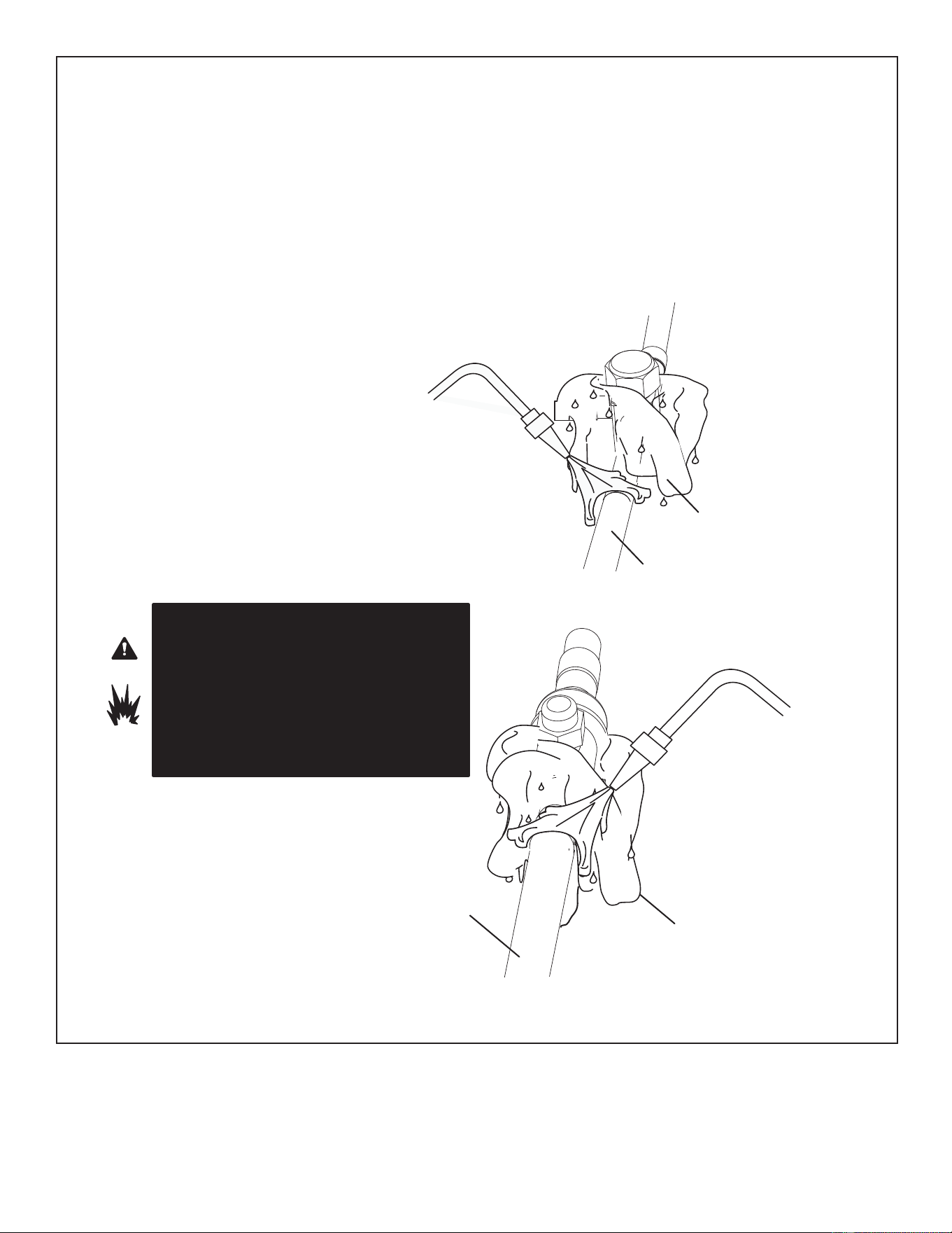
FIGURE 9. Brazing Procedures (Cont’d)
WHEN BRAZING LINE SET TO
SERVICE VALVES, POINT FLAME
AWAY FROM SERVICE VALVE.
LIQUID LINE SERVICE VALVE
LIQUID LINE
BRAZE LINE SET
Wrap both service valves with water-saturated cloths as illustrated here and as mentioned in step 4, before brazing to line set. Cloths
must remain water-saturated throughout the brazing and cool-down process.
WATER-SATURATED
CLOTH
IMPORTANT - Allow braze joint to cool. Apply additional
water-saturated cloths to help cool brazed joint. Do not
remove water-saturated cloths until piping has cooled.
Temperatures above 250ºF will damage valve seals.
6
SUCTION LINE
WATER-SATURATED
CLOTH
SUCTION LINE SERVICE
VALVE
Disconnect manifold gauge set from service ports after all connections have been brazed. Apply additional water-saturated cloths to both
service valves to cool piping. Once piping is cool, remove all water-saturated cloths.
WHEN BRAZING LINE SET TO
SERVICE VALVES, POINT FLAME
AWAY FROM SERVICE VALVE.
PREPARATION FOR NEXT STEP
7
WRAP SERVICE VALVES
To help protect service valve seals during brazing, wrap water-saturated cloths around service valve bodies and copper tube stubs. Use
additional water-saturated cloths underneath the valve body to protect the base paint.
4
FLOW NITROGEN
Flow regulated nitrogen (at 1 to 2 psig) through the refrigeration gauge set into the valve stem port connection on the liquid service valve
and out of the suction / vapor valve stem port. See steps 3A, 3B and 3C on manifold gauge set connections.
5
WARNING
FIRE, PERSONAL INJURY, OR PROPERTY DAMAGE
may result if you do not wrap a water-saturated cloth
around both liquid and suction line service valve bodies
and copper tube stub while brazing the line set! The braze,
when complete, must be quenched with water to absorb
any residual heat.
Do not open service valves until refrigerant lines and
indoor coil have been leak-tested and evacuated.
Refer to Installation manual.
22 49-5000962 Rev. 0
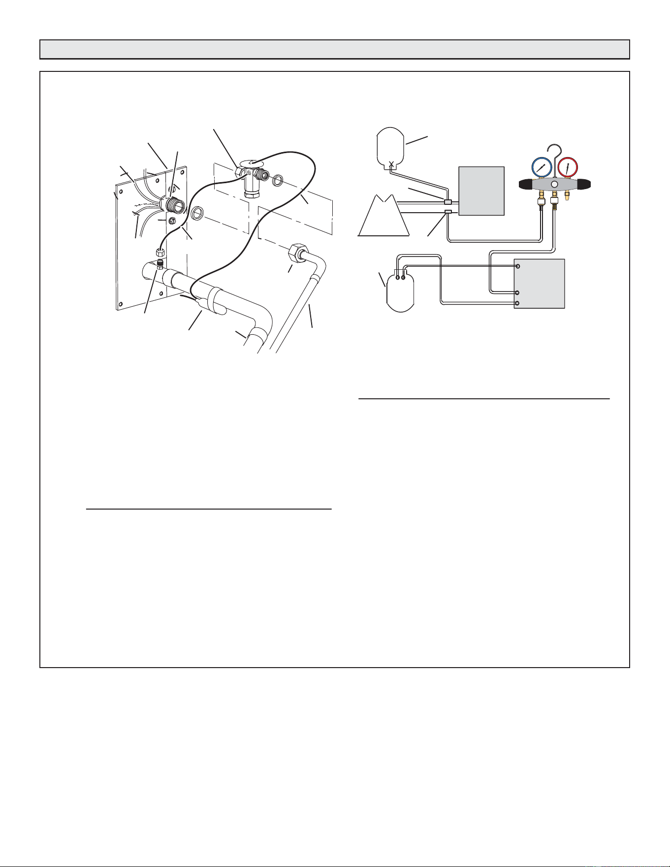
Flushing Line Set and Indoor Coil
FIGURE 10. Removing Metering Device and Flushing
LOW HIGH
EXISTING
INDOOR
UNIT
GAUGE
MANIFOLD
INVERTED CYLINDER
CONTAINS CLEAN
HCFC22* TO BE USED
FOR FLUSHING.
LIQUID LINE SERVICE
VALVE
INLET
DISCHARGE
TANK
RETURN
CLOSED
OPENED
RECOVERY CYLINDER
RECOVERY MACHINE
NEW
OUTDOOR
UNIT
VAPOR LINE
SERVICE VALVE
VAPOR
LIQUID
1
A Inverted HCFC-22 cylinder with clean refrigerant* to the vapor service
valve.
B HCFC-22 gauge set (low side) to the liquid line valve.
C HCFC-22 gauge set center port to inlet on the recovery machine with an
empty recovery tank to the gauge set.
D Connect recovery tank to recovery machines per machine instructions.
CONNECT GAUGES AND EQUIPMENT FOR
FLUSHING PROCEDURE
A
B
C
D
2
B
FLUSHING LINE SET
A Set the recovery machine for liquid recovery and start the
recovery machine. Open the gauge set valves to allow the
recovery machine to pull a vacuum on the existing system line
set and indoor unit coil.
B Invert the cylinder of clean HCFC-22* and open its valve to allow
liquid refrigerant to flow into the system through the vapor line
valve. Allow the refrigerant to pass from the cylinder and through
the line set and the indoor unit coil before it enters the recovery
machine.
C After all of the liquid refrigerant has been recovered, switch the
recovery machine to vapor recovery so that all of the HCFC-22
vapor is recovered. Allow the recovery machine to pull the
system down to 0.
D Close the valve on the inverted HCFC-22 drum and the gauge
set valves. Pump the remaining refrigerant out of the recovery
machine and turn the machine off.
The line set and indoor unit coil must be flushed with at least the
same amount of clean refrigerant* that previously charged the
system. Check the charge in the flushing cylinder before
proceeding.
3
SENSING
LINE
TYPICAL EXISTING EXPANSION VALVE REMOVAL
PROCEDURE (UNCASED COIL SHOWN)
TWO PIECE PATCH PLATE
(UNCASED COIL ONLY)
VAPOR
LINE
DISTRIBUTOR
ASSEMBLY
DISTRIBUTOR
TUBES
LIQUID
LINE
MALE EQUALIZER
LINE FITTING
EQUALIZER
LINE
CHECK
EXPANSION
VALVE
TEFLON
®
RING
STUB END
TEFLON
®
RING
SENSING BULB
LIQUID LINE
ORIFICE
HOUSING
LIQUID LINE
ASSEMBLY WITH
BRASS NUT
A On fully cased coils, remove the coil access and plumbing panels.
B Remove any shipping clamps holding the liquid line and distributor
assembly.
C Disconnect the equalizer line from the check expansion valve
equalizer line fitting on the vapor line.
D Remove the vapor line sensing bulb.
E Disconnect the liquid line from the check expansion valve at the liquid
line assembly.
F Disconnect the check expansion valve from the liquid line orifice
housing. Take care not to twist or damage distributor tubes during this
process.
G Remove and discard check expansion valve and the two Teflon
®
rings.
H Use a field-provided fitting to temporary reconnect the liquid line to the
indoor unit's liquid line orifice housing.
1
*IMPORTANT - Clean refrigerant is any refrigerant in a system that has not had compressor burn out. If the system
has experienced burn out, it is recommended that the existing line set and indoor coil be replaced.
49-5000962 Rev. 0 23
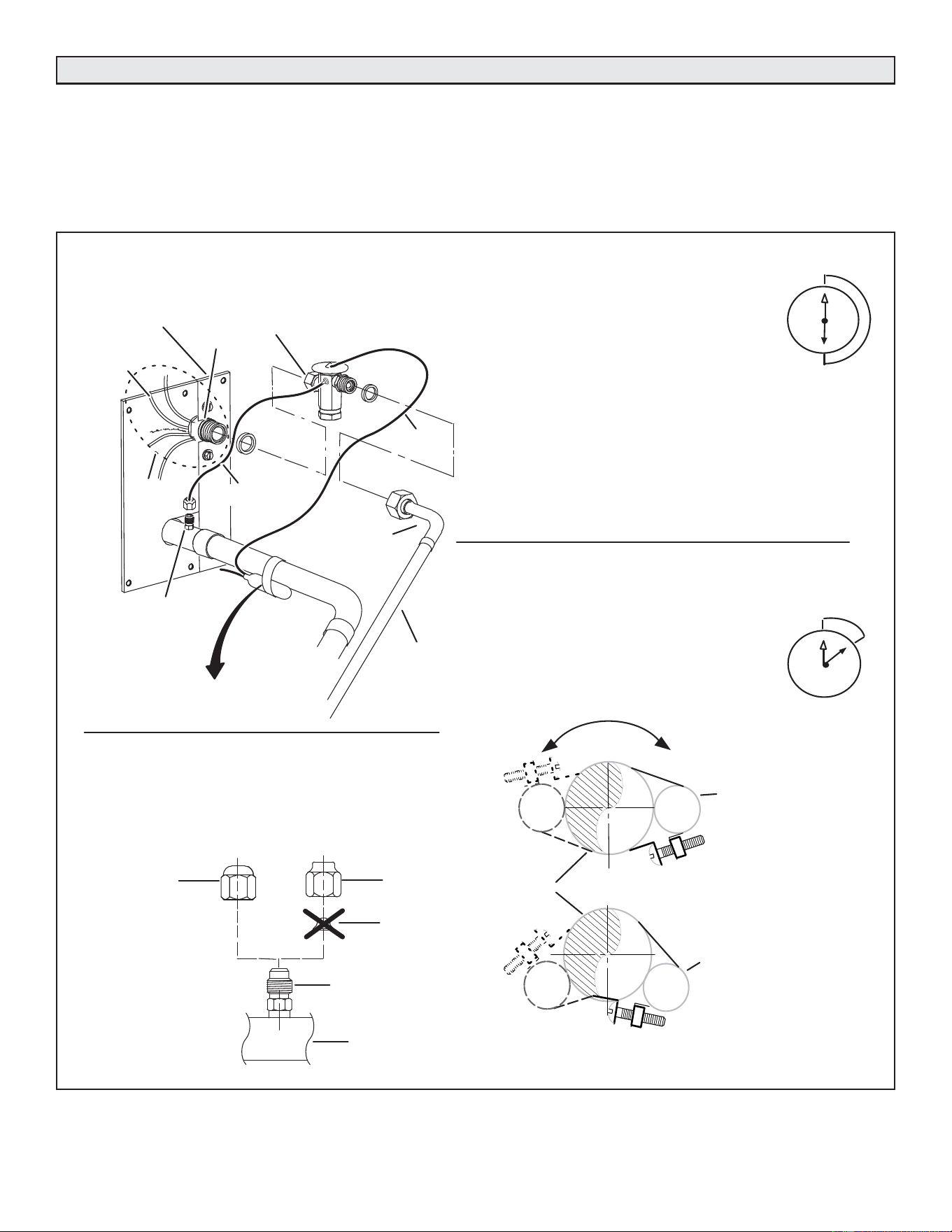
Installing Indoor Metering Device
This outdoor unit is designed for use in systems that use an
expansion valve metering device (purchased separately) at
the indoor coil. See the NS16A Product Specifications for
approved expansion valve kit match ups.
The expansion valve unit must be installed inside the
cabinet. In applications where an uncased coil is being
installed in a field-provided plenum, install the expansion
valve in a manner that will provide access for field servicing
of the expansion valve. Refer to below illustration for
reference during installation of expansion valve unit.
FIGURE 11.
A Attach the vapor line sensing bulb in the proper
orientation as illustrated to the right using the clamp and
screws provided.
NOTE — Confirm proper thermal contact between vapor line
and expansion bulb before insulating the sensing bulb once
installed.
B Connect the equalizer line from the expansion valve to
the equalizer vapor port on the vapor line. Finger tighten
the flare nut plus 1/8 turn (7 ft-lbs) as illustrated below.
TWO PIECE
PATCH PLATE
(UNCASED
COIL ONLY)
VAPOR
LINE
LIQUID LINE
ORIFICE
HOUSING
DISTRIBUTOR
TUBES
LIQUID LINE
MALE EQUALIZER LINE
FITTING (SEE
EQUALIZER LINE
INSTALLATION FOR
FURTHER DETAILS)
SENSING
LINE
EQUALIZER
LINE
EXPANSION
VALVE
TEFLON
®
RING
(Uncased Coil Shown)
Sensing bulb insulation is required if
mounted external to the coil casing. See
sensing bulb installation for bulb positioning.
STUB
END
TEFLON
®
RING
LIQUID LINE
ASSEMBLY WITH
BRASS NUT
DISTRIBUTOR
ASSEMBLY
A Remove the field-provided fitting that temporary
reconnected the liquid line to the indoor unit's distributor
assembly.
B Install one of the provided Teflon
®
rings around the
stubbed end of the expansion valve and lightly lubricate
the connector threads and expose surface of the Teflon
®
ring with refrigerant oil.
C Attach the stubbed end of the expansion valve to the
liquid line orifice housing. Finger tighten and use an
appropriately sized wrench to turn an additional 1/2 turn
clockwise as illustrated in the figure above, or 20 ft-lb.
D Place the remaining Teflon
®
washer around the other
end of the expansion valve. Lightly lubricate connector
threads and expose surface of the Teflon
®
ring with
refrigerant oil.
E Attach the liquid line assembly to the expansion valve.
Finger tighten and use an appropriately sized wrench to
turn an additional 1/2 turn clockwise as illustrated in the
figure above or 20 ft-lb.
ON 7/8” AND LARGER LINES,
MOUNT SENSING BULB AT
EITHER THE 4 OR 8 O'CLOCK
POSITION. NEVER MOUNT ON
BOTTOM OF LINE.
12
ON LINES SMALLER THAN
7/8”, MOUNT SENSING
BULB BETWEEN THE 3 AND
9 O'CLOCK POSITIONS.
12
BULB
VAPOR LINE
NOTE — NEVER MOUNT ON BOTTOM OF LINE.
BULB
BULB
BULB
VAPOR LINE
FLARE NUT
COPPER FLARE
SEAL BONNET
MALE BRASS EQUALIZER
LINE FITTING
FLARE SEAL CAP
OR
1
2
3
4
5
6
7
8
9
10
11
12
1/2 Turn
SENSING BULB INSTALLATION
EQUALIZER LINE INSTALLATION
1
2
3
4
5
6
7
8
9
10
11
12
1/8 Turn
A Remove and discard either the flare seal cap or flare nut
with copper flare seal bonnet from the equalizer line port
on the vapor line as illustrated in the figure to the right.
B Remove and discard either the flare seal cap or flare nut
with copper flare seal bonnet from the equalizer line port on
the vapor line as illustrated in the figure to the right.
INDOOR EXPANSION VALVE INSTALLATION
9 O'CLOCK TO
3 O'CLOCK
24 49-5000962 Rev. 0
Leak Testing the System
Leak detector must be capable of sensing A2L refrigerant.
IMPORTANT
The Environmental Protection Agency (EPA) prohibits
the intentional venting of HFC refrigerants during
maintenance, service, repair and disposal of appliance.
Approved methods of recovery, recycling or reclaiming
must be followed.
IMPORTANT
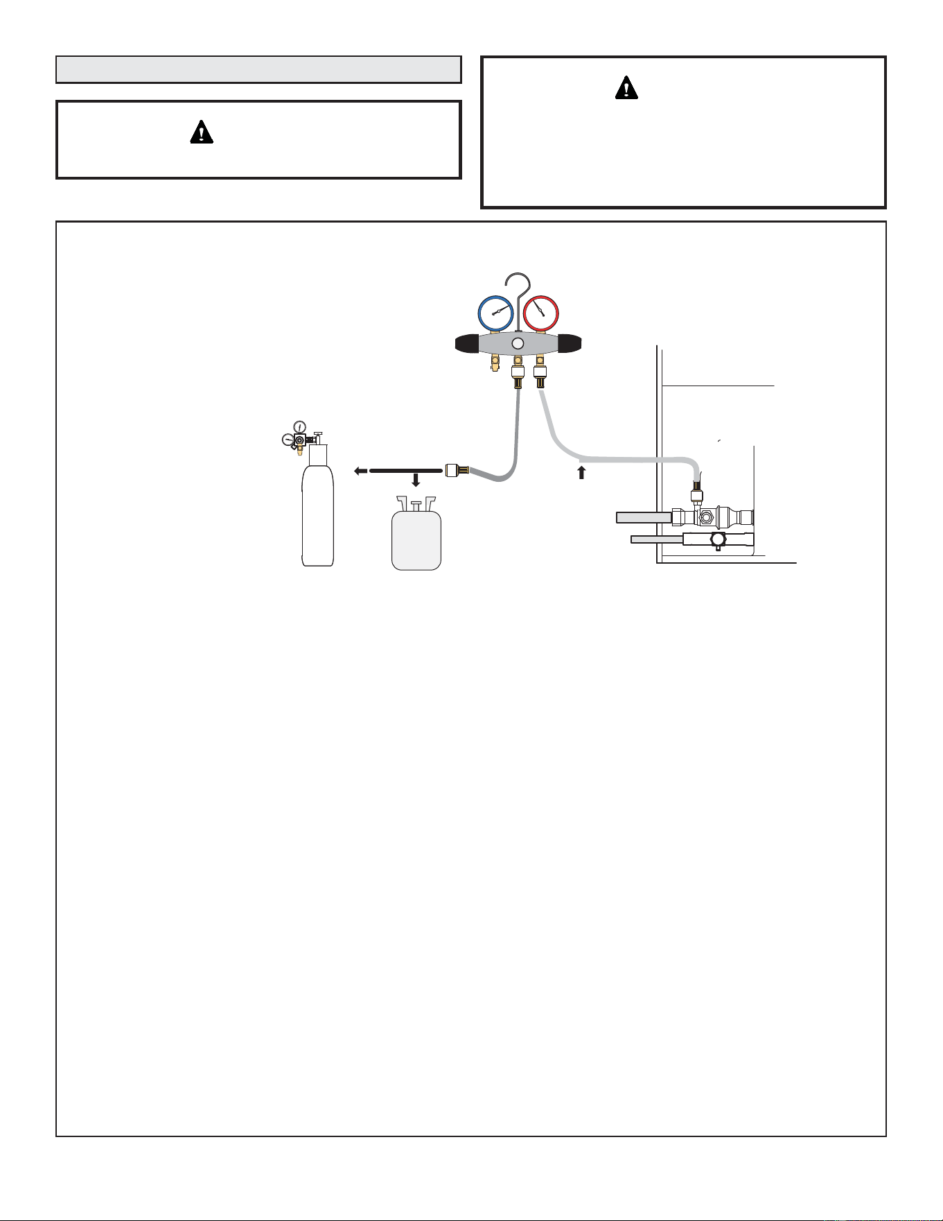
FIGURE 12. System Leak Test
TO VAPOR
SERVICE VALVE
R-454B
MANIFOLD GAUGE SET
OUTDOOR UNIT
HIGH
LOW
1
2
A
B
NITROGEN
NOTE - Position
canister to deliver
liquid refrigerant.
A - With both manifold valves closed, connect the cylinder of R-454B refrigerant to the center port of the
manifold gauge set. Open the valve on the R-454B cylinder (vapor only).
B -Open the high pressure side of the manifold to allow R-454B into the line set and indoor unit. Weigh in
a trace amount of R-454B. [A trace amount is a maximum of two ounces (57 g) refrigerant or three
pounds (31 kPa) pressure.] Close the valve on the R-454B cylinder and the valve on the high
pressure side of the manifold gauge set. Disconnect the R-454B cylinder.
C -Connect a cylinder of nitrogen with a pressure regulating valve to the center port of the manifold gauge
set.
D -Adjust nitrogen pressure to 160 psig (1103 kPa). Open the valve on the high side of the manifold gauge set
in order to pressurize the line set and the indoor unit.
E - After a few minutes, open one of the service valve ports and verify that the refrigerant added to the
system earlier is measurable with a leak detector. Once leak detector is confirmed operational, leak
check the entire system (field joints and line set included) to a sensitivity of 5 grams per year of
refrigerant.
F - After leak testing, disconnect gauges from service ports.
After the line set has been connected to the indoor and outdoor units, check the line set connections and
indoor unit for leaks. Use the following procedure to test for leaks:
A - Connect the high pressure hose of an R-454B manifold gauge set to the vapor valve service port.
NOTE - Normally, the high pressure hose is connected to the liquid line port. However, connecting it
to the vapor port better protects the manifold gauge set from high pressure damage.
B -With both manifold valves closed, connect the cylinder of R-454B refrigerant to the center port of
the manifold gauge set.
CONNECT GAUGE SET
TEST FOR LEAKS
NOTE - Later in the procedure, the R-454B container will be replaced by the nitrogen container.
LEAK TEST
49-5000962 Rev. 0 25
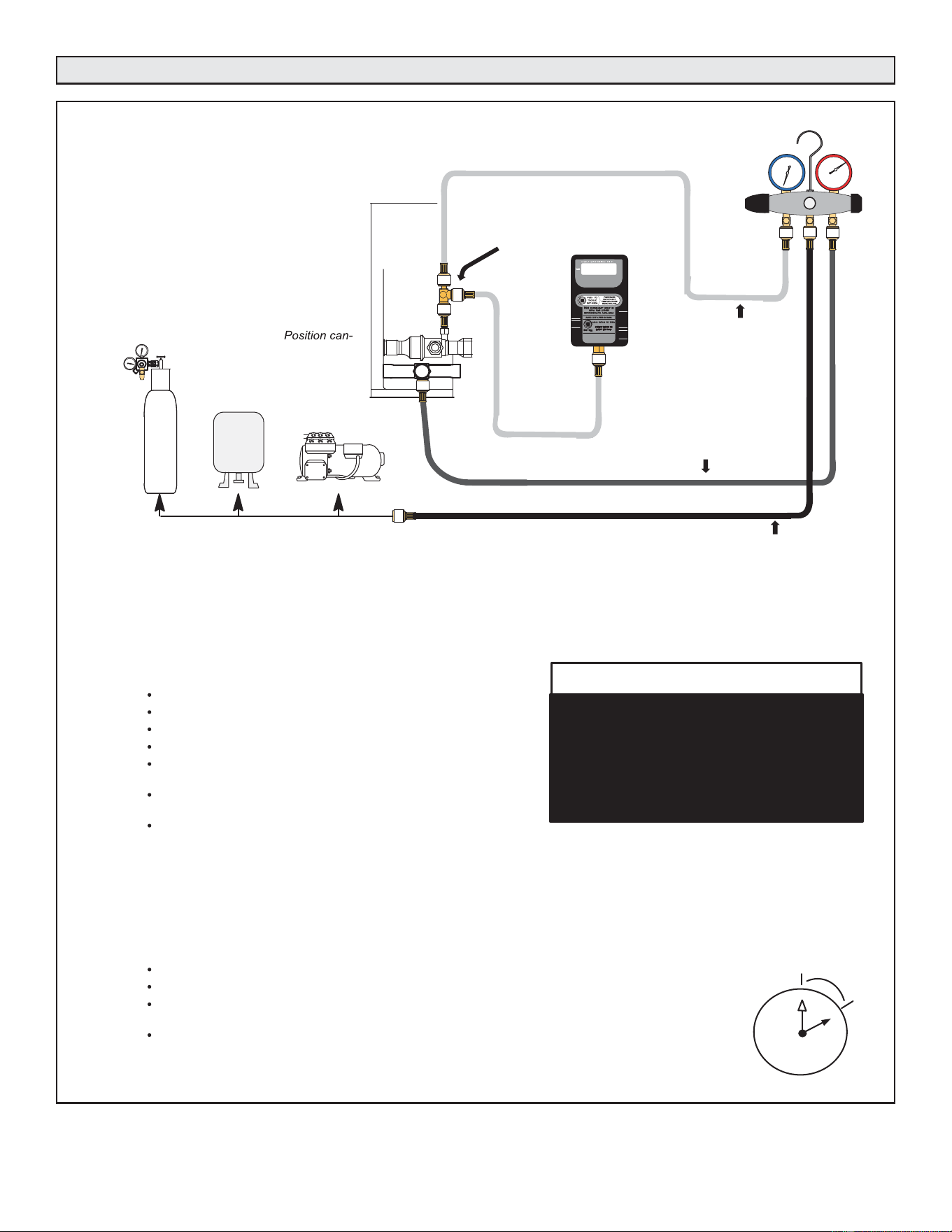
Evacuating Line Set and Indoor Coil
FIGURE 13. Evacuating the System
A - Open both manifold valves and start the vacuum pump.
B - Evacuate the line set and indoor unit to an absolute pressure of 23,000 microns (29.01 inches of mercury).
NOTE - During the early stages of evacuation, it is desirable to close the manifold gauge valve at least once. A rapid rise in pressure
indicates a relatively large leak. If this occurs, repeat the leak testing procedure.
NOTE - The term absolute pressure means the total actual pressure above absolute zero within a given volume or system. Absolute
pressure in a vacuum is equal to atmospheric pressure minus vacuum pressure.
C - When the absolute pressure reaches 23,000 microns (29.01 inches of
mercury), perform the following:
Close manifold gauge valves.
Close valve on vacuum pump.
Turn off vacuum pump.
Disconnect manifold gauge center port hose from vacuum pump.
Attach manifold center port hose to a nitrogen cylinder with pressure
regulator set to 160 psig (1103 kPa) and purge the hose.
Open manifold gauge valves to break the vacuum in the line set and indoor
unit.
Close manifold gauge valves.
D - Shut off the nitrogen cylinder and remove the manifold gauge hose from the cylinder. Open the manifold gauge valves to release the
nitrogen from the line set and indoor unit.
E - Reconnect the manifold gauge to the vacuum pump, turn the pump on, and continue to evacuate the line set and indoor unit until the
absolute pressure does not rise above 500 microns (29.9 inches of mercury) within a 20-minute period after shutting off the vacuum pump
and closing the manifold gauge valves.
F - When the absolute pressure requirement above has been met, disconnect the manifold hose from the vacuum pump and connect it to a
cylinder of R-454B positioned to deliver liquid refrigerant. Open the manifold gauge valve 1 to 2 psig in order to release the vacuum in the
line set and indoor unit.
G - Perform the following:
Close manifold gauge valves.
Shut off R-454B cylinder.
Reinstall service valve cores by removing manifold hose from service valve. Quickly install cores with core
tool while maintaining a positive system pressure.
Replace stem caps and finger tighten them, then tighten an additional one-sixth (1/6) of a turn as illustrated.
OUTDOOR
UNIT
TO VAPOR
SERVICE VALVE
TO LIQUID LINE
SERVICE VALVE
MICRON
GAUGE
VACUUM PUMP
1/4 SAE TEE WITH SWIVEL
COUPLER
500
MANIFOLD
GAUGE SET
R-454B
RECOMMEND
MINIMUM 3/8” HOSE
A - Connect low side of manifold gauge set with
1/4 SAE in-line tee to vapor line service valve
B - Connect high side of manifold gauge set to
liquid line service valve
C - Connect available micron gauge connector
on the 1/4 SAE in-line tee.
D - Connect the vacuum pump (with vacuum
gauge) to the center port of the manifold
gauge set. The center port line will be used
later for both the R-454B and nitrogen
containers.
HIGH
LOW
1
2
3
4
5
6
7
8
9
10
11
12
1/6 TURN
NITROGEN
3
CONNECT GAUGE SET
A
B
C
D
4
EVACUATE THE SYSTEM
NOTE - Remove cores from service valves (if not already done).
Possible equipment damage.
Avoid deep vacuum operation. Do not use
compressors to evacuate a system.
Extremely low vacuum can cause internal
arcing and compressor failure. Damage
caused by deep vacuum operation will
void warranty.
WARNING !
NOTE -
ister to deliver liquid
refrigerant.
EVACUATION
26 49-5000962 Rev. 0
Electrical – Circuit Sizing and Wire Routing
Use a thermocouple or thermistor electronic vacuum
gauge that is calibrated in microns. Use an instrument
capable of accurately measuring down to 50 microns.
IMPORTANT
Fire Hazard. Use of aluminum wire with this product may
UHVXOWLQD¿UHFDXVLQJSURSHUW\GDPDJHVHYHUHLQMXU\RU
death. Use copper wire only with this product.
WARNING
Failure to use properly sized wiring and circuit breaker
may result in property damage. Size wiring and circuit
EUHDNHUVSHU3URGXFW6SHFL¿FDWLRQVEXOOHWLQ(+%DQG
unit rating plate.
WARNING
Possible equipment damage.
Avoid deep vacuum operation. Do not use compressors
to evacuate a system. Extremely low vacuum can cause
internal arcing and compressor failure. Damage caused
by deep vacuum operation will void warranty.
WARNING
In the U.S.A., wiring must conform with current local codes
and the current National Electric Code (NEC). In Canada,
wiring must conform with current local codes and the current
Canadian Electrical Code (CEC).
Refer to the furnace or air handler installation instructions
for additional wiring application diagrams and refer to unit
nameplate for minimum circuit ampacity and maximum
overcurrent protection size.
24VAC TRANSFORMER
Use the transformer provided with the furnace or air handler
for low-voltage control power (24VAC - 40 VA minimum).
Evacuating the system of non-condensables is critical for
proper operation of the unit. Non-condensables are defined
as any gas that will not condense under temperatures and
pressures present during operation of an air conditioning
system. Non-condensables and water suction combine with
refrigerant to produce substances that corrode copper piping
and compressor parts.
Unit must be installed with GE Appliances approved
refrigerant detection system (RDS) and sensor.
Do not operate system until refrigerant detection system is
verified to be in good working order.
Refer to the unit nameplate for minimum circuit ampacity, and maximum
fuse or circuit breaker (HACR per NEC). Install power wiring and properly
sized disconnect switch.
NOTE — Units are approved for use only with copper conductors.
Ground unit at disconnect switch or to an earth ground.
SIZE CIRCUIT AND INSTALL SERVICE
DISCONNECT SWITCH
NOTE — 24VAC, Class II circuit connections are made in the control
panel.
Install room thermostat (ordered separately) on an inside wall
approximately in the center of the conditioned area and 5 feet (1.5m) from
the floor. It should not be installed on an outside wall or where it can be
affected by sunlight or drafts.
THERMOSTAT
5 FEET
(1.5M)
INSTALL THERMOSTAT
SERVICE
DISCONNECT
SWITCH
MAIN FUSE BOX/
BREAKER PANEL
49-5000962 Rev. 0 27
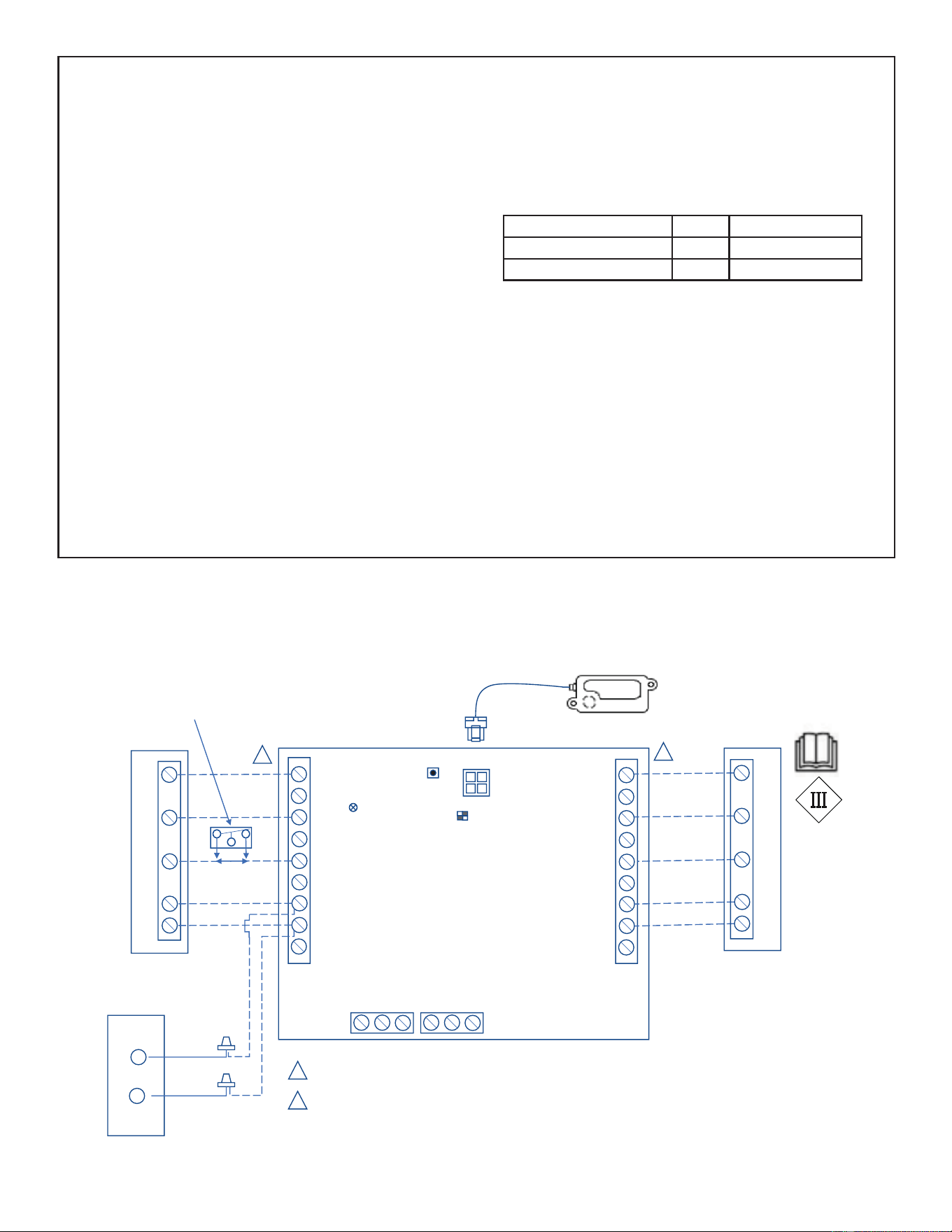
ROUTING HIGH VOLTAGE, GROUND AND CONTROL WIRING
HIGH VOLTAGE / GROUND WIRES
Any excess high voltage field wiring should be trimmed
and secured away from any low voltage field wiring. To
facilitate a conduit, a cutout is located in the bottom of the
control panel. Connect conduit to the control panel using
a proper conduit fitting.
NOTE - Wire tie provides low voltage control wire strain
relief and maintains separation of field-installed low and
high voltage circuits.
NOTE - For proper voltages, select thermostat wire
(control wires) gauge per table at right.
NOTE - Do not bundle any excess 24VAC control wires
inside control panel.
Install low voltage wiring from outdoor to indoor unit
and from thermostat to indoor unit as illustrated.
A - Run 24VAC control wires through hole with grommet
and secure with provided wire tie.
B - Make 24VAC thermostat wire connections. Locate the
two wires from the contactor and make connection
using field-provided wire nuts:
• Yellow to Y1
• Black to C (common)
Wire Run Length AWG# Insulation Type
Less than 100’ (30 meters) 18 Temperature Rating
More than 100’ (30 meters) 16 35ºC Minimum
Single-Stage Outdoor Unit with Single-Stage Indoor Unit
TSTAT
INDOOR
NO COM NC
NO COM NC
ZONING
ALARM
W1
W2
G
R
O/B
DS
C
Y2
Y1
W1
W2
G
R
O/B
DS
C
Y2
Y1
SENSOR #1
SW1
SW2
LED
W1
C
G
R
Y1
Y1
C
Thermostat
W1
C
G
R
Y1
IndoorUnit
Outdoor Unit
1
2
1
2
Thermostat / Outdoor Unit Terminal Block (BLACK)
Indoor Unit Terminal Block (BLUE)
Class II Voltage Field Wiring
Black
Yellow
RDS Sensor
Single-Stage Furnace/
Single-Stage Air Handler
RDS Blower Control Board - 24 Volt
Cat # (27A05)
OPTIONAL
N.C. CONDENSATE
FLOAT SWITCH
FIGURE 15
FIGURE 14. Route Wiring
28 49-5000962 Rev. 0
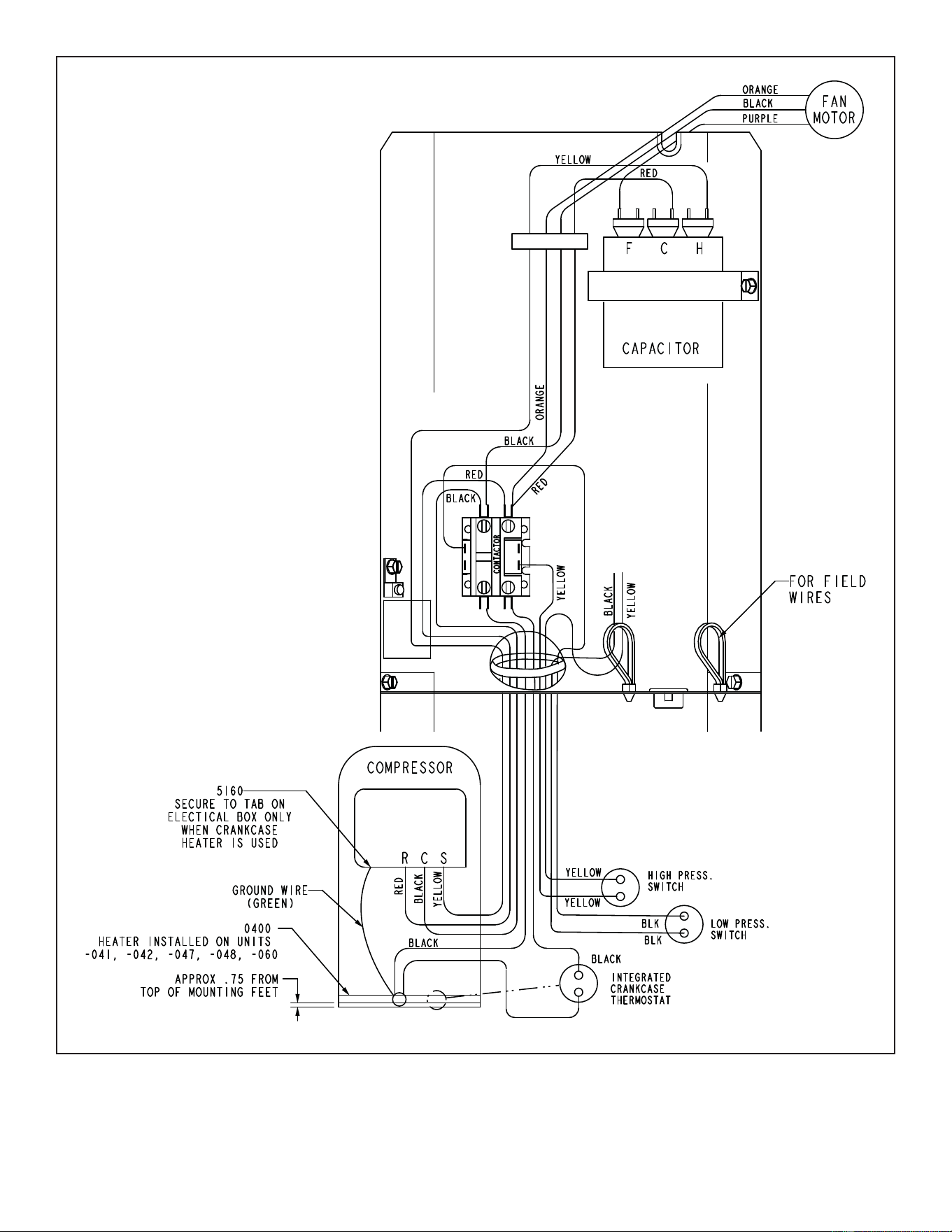
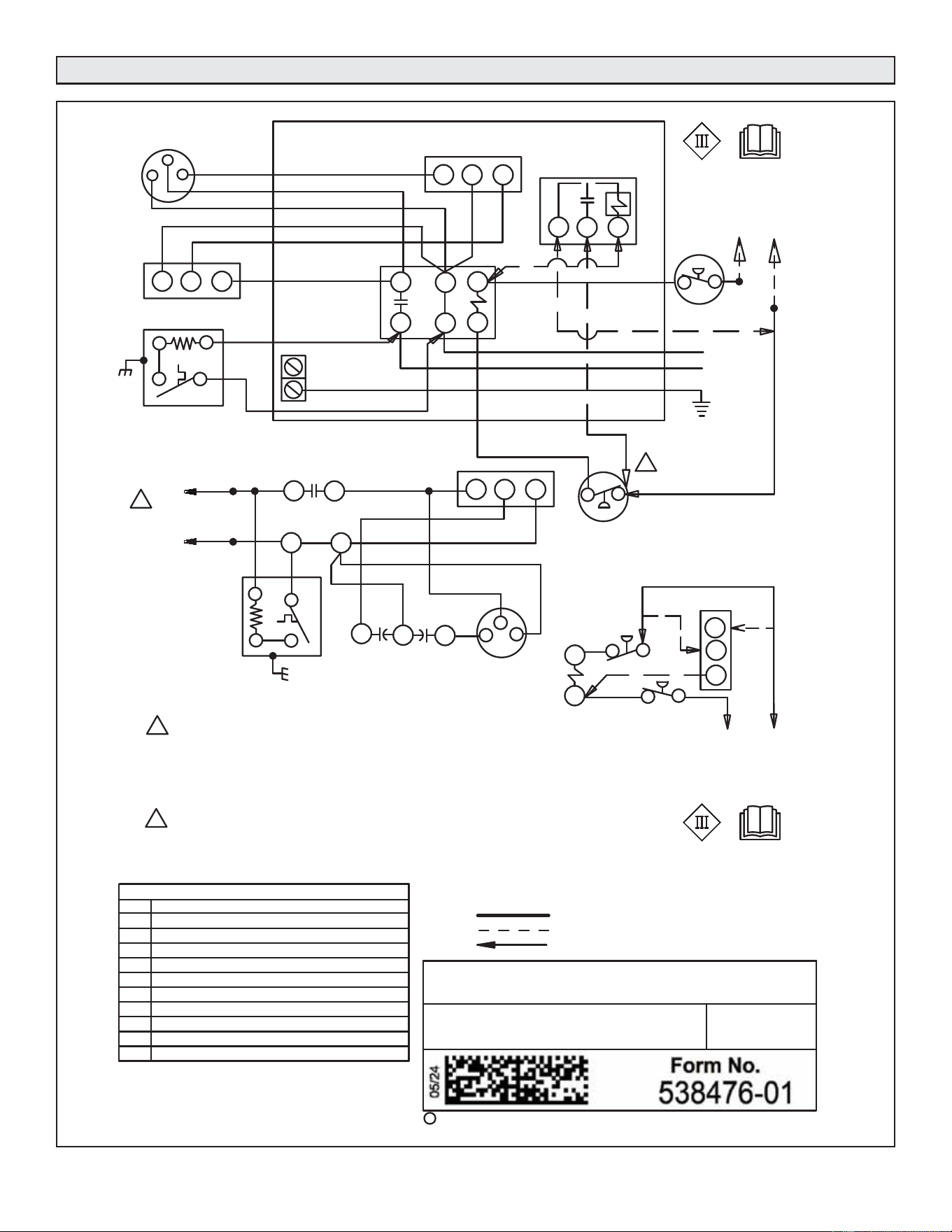
FIGURE 16. Typical Factory Wiring Diagram – -018, -024, -030, -036, -048, and -060 Units Only
49-5000962 Rev. 0 29
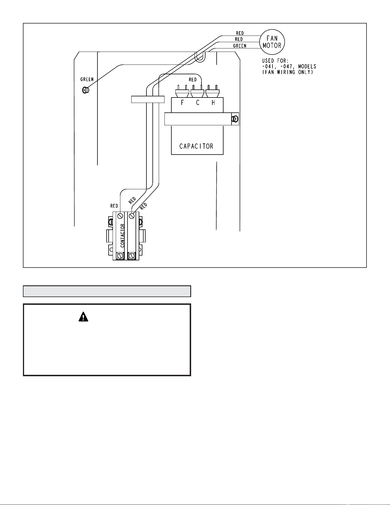
FIGURE 17. Typical Factory Wiring – -041, -047 and -059 Units Only
System Operation
Some scroll compressors have an internal vacuum
protector that will unload scrolls when suction pressure
goes below 20 psig. A hissing sound will be heard when
the compressor is running unloaded. Protector will reset
when low pressure in system rises above 40 psig.
DO NOT REPLACE COMPRESSOR.
IMPORTANT
The outdoor unit and indoor blower will cycle on and off as
dictated by demands from the room thermostat. When the
thermostat’s blower switch is in the ON position, the indoor
blower will operate continuously.
HIGH PRESSURE SWITCH (S4)
NS16A units are equipped with a high-pressure switch that
is factory-wired and located in the liquid line.
The switch is a single pole, single throw (SPST), auto-reset
switch which is normally closed and removes power from the
compressor when discharge pressure rises above factory
setting at 590 ± 10 psig; resets at 418 ± 5 psig.
LOW PRESSURE SWITCH (S87)
This unit is equipped with a low pressure switch which is
located on the suction line. The SPST, normally closed
pressure switch opens when the suction pressure drops
below the factory setting of 40 psig ± 5 psig and automatically
resets at 90 psig ± 5 psig.
CRANKCASE HEATER (HR1) AND THERMOSTAT (S40)
Compressors in some models are equipped with a 40
watt or 70 watt, belly band type crankcase heater. HR1
prevents liquid from accumulating in the compressor. HR1
is controlled by a single pole, single throw thermostat switch
(S40) located on the belly band.
When compressor shell temperature drops below 50° F the
thermostat closes energizing HR1. The thermostat will open,
de-energizing HR1 once compressor shell temperature
reaches 70° F.
30 49-5000962 Rev. 0
Your heating and air conditioning system should be
inspected and maintained yearly (before the start of the
cooling and heating seasons) by a licensed professional
HVAC technician. You can expect the technician to check
the following items. These checks may only be conducted by
a licensed professional HVAC technician.
Outdoor Unit
1. Inspect component wiring for loose, worn or damaged
connections. Also check for any rubbing or pinching of
wires. Confirm proper voltage plus amperage of outdoor
unit. Mount fan blade to end of motor shaft.
2. Check the cleanliness of outdoor fan and blade assemblies.
Check condition of fan blades (cracks). Clean or replace
them, if necessary.
3. Inspect base pan drains for debris and clean as necessary.
4. Inspect the condition of refrigerant piping and confirm that
pipes are not rubbing copper-to-copper. Also, check the
condition of the insulation on the refrigerant lines. Repair,
correct, or replace as necessary.
5. Test capacitor. Replace as necessary.
6. Inspect contactor contacts for pitting or burn marks.
Replace as necessary.
7. Check outdoor fan motor for worn bearings/bushings.
Replace as necessary.
8. Inspect and clean outdoor coils, if necessary and note any
damage to coils or signs of leakage.
Indoor Unit (Air Handler or Furnace)
1. Inspect component wiring for loose, worn or damaged
connections. Confirm proper voltage plus amperage
indoor unit.
2. Inspect and clean or replace air filters in indoor unit.
3. Check the cleanliness of indoor blower and clean blower,
if necessary.
4. Inspect the evaporator coil (Indoor) drain pans and
condensate drains for rust, debris, obstructions, leaks or
cracks. Pour water in pans to confirm proper drainage
from the pan through to the outlet of the pipe. Clean or
replace as necessary.
5. Inspect and clean evaporator (indoor) coil, if necessary.
6. Inspect the condition of the refrigerant lines and confirm
that pipes are not rubbing copper-to-copper. Also, ensure
that refrigerant pipes are not being affected by indoor
air contamination. Check condition of insulation on the
refrigerant lines. Repair, correct, or replace as necessary.
7. Inspect the duct system for leaks or other problems.
Repair or replace as necessary.
8. Check for bearing/bushing wear on indoor blower motor.
Replace as necessary.
9. Indoor unit inspections of gas- or oil-fired furnaces will
also include inspection and cleaning of the burners, and
a full inspection of the gas valve, heat exchanger and flue
(exhaust) system.
10. Check functionality of refrigerant detection system.
11. Inspect refrigerant detection sensor.
General System Test with System Operating
1. Your technician should perform a general system test. He
will turn on the air conditioner to check operating functions
such as the startup and shutoff operation. He will also
check for unusual noises or odors, and measure indoor/
outdoor temperatures and system pressures as needed.
2. The technician will check the refrigerant charge per the
charging sticker information on the outdoor unit.
3. Verify that system total static pressure and airflow settings
are within specific operating parameters.
4. Verify correct temperature drop across indoor coil.
Maintenance
Failure to follow instructions will cause damage to
the unit.
This unit is equipped with an aluminum coil. Aluminum
coils may be damaged by exposure to solutions with
a pH below 5 or above 9. The aluminum coil should be
cleaned using potable water at a moderate pressure
(less than 50psi). If the coil cannot be cleaned using
water alone, GE Appliances recommends use of a
coil cleaner with a pH in the range of 5 to 9. The coil
must be rinsed thoroughly after cleaning.
In coastal areas, the coil should be cleaned with
potable water several times per year to avoid
corrosive buildup (salt).
NOTICE
49-5000962 Rev. 0 31
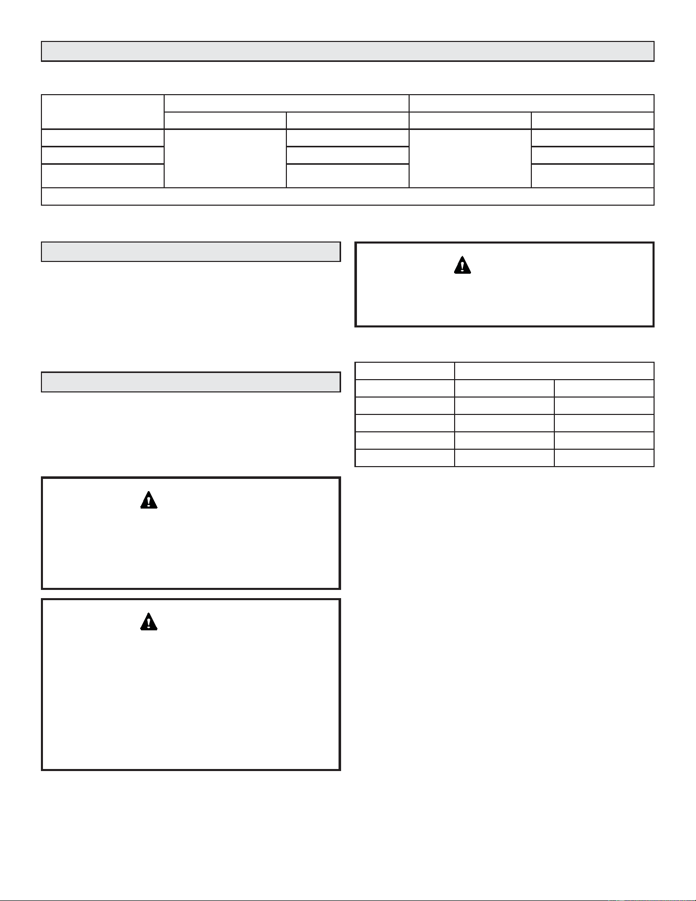
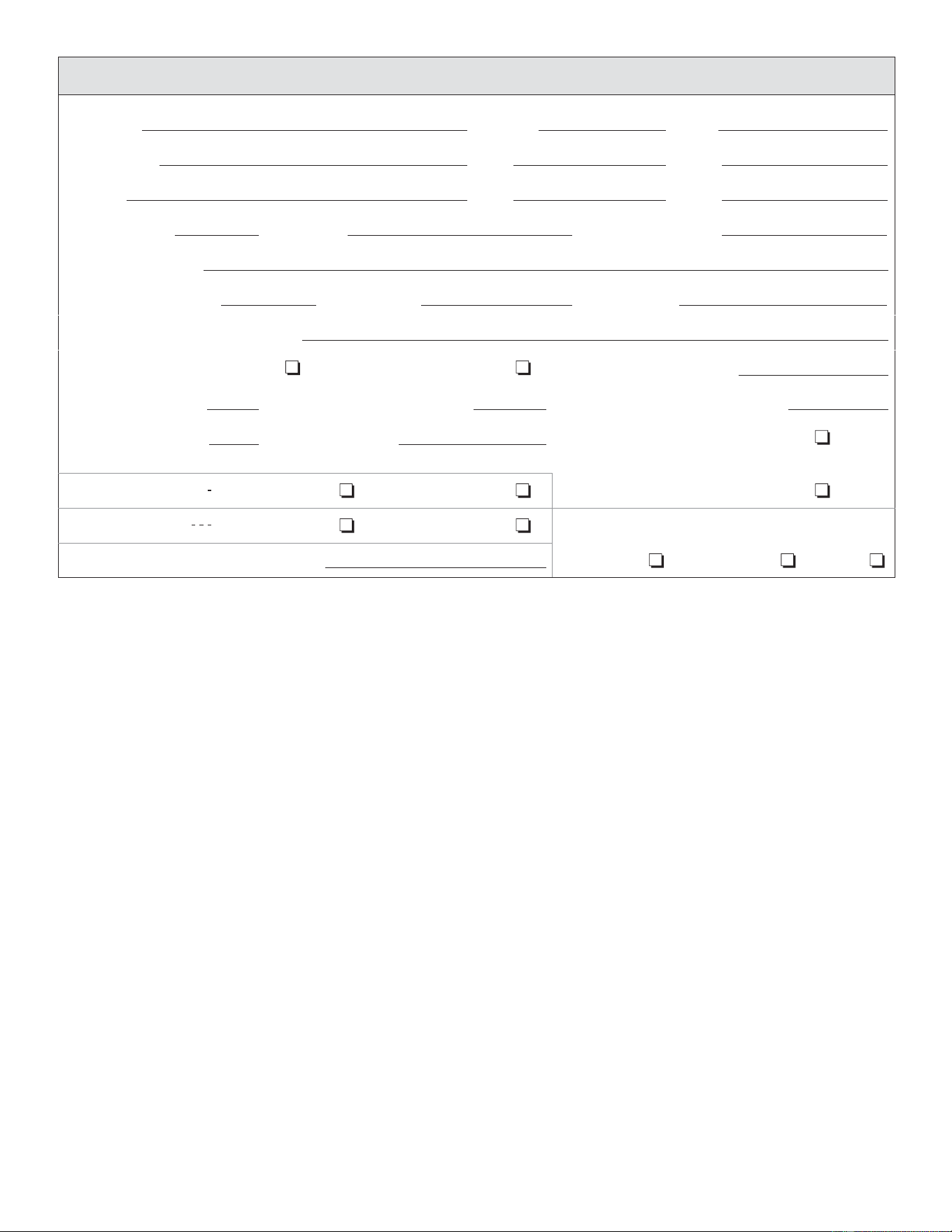
Start-Up and Performance Checklist
Job Name Job no. Date
Job Location City State
Installer City State
Unit Model No. Serial No. Service Technician
Nameplate Voltage
Rated Load Ampacity Compressor Outdoor Fan
Maximum Fuse or Circuit Breaker
Electrical Connections Tight? Indoor Filter clean? Supply Voltage (Unit Off)
Indoor Blower RPM S.P. Drop Over Indoor (Dry) Outdoor Coil Entering Air Temp.
Discharge Pressure Suction Pressure Refrigerant Charge Checked?
Refrigerant Lines: Leak Checked? Properly Insulated? Outdoor Fan Checked?
Service Valves: Fully Opened? Caps Tight? Thermostat
Voltage With Compressor Operating Calibrated? Properly Set? Level?
32 49-5000962 Rev. 0
Typical Field Wiring
FIGURE 18. Typical Field Wiring – All Units Except -041, -047 and -059
Supersedes
Litho U.S.A.
C
1
GROUND
LUG
S4
HIGH
PRESSURE
SWITCH
NOTE-
FOR USE WITH COPPER CONDUCTORS
ONLY. REFER TO UNIT RATING PLATE
FOR MINIMUM CIRCUIT AMPACITY AND
MAXIMUM OVERCURRENT PROTECTION SIZE
L1
1
F
C
H
2
31
R
S
C
PURPLE
BLACK
ORANGE
RED
YELLOW
OUTDOOR
FAN
BLACK
DUAL
CAPACITOR
L2
L1
GROUND
TO 24 VAC POWER
SOURCE
20 VA MINIMUM
NEC CLASS 2
C
Y1
A4
TIMED OFF
CONTROL
COMPRESSOR
CONTACTOR
COMPRESSOR
CRANKCASE
HEATER
K1-1
L2
208-230/ 60/
1
BLACK
YELLOW
RED
ORANGE
RED
BLACK
H
C
F
B4
C12
CS
R
B1
A4
CONTROL-TIMED OFF
KEY
COMPONENT
B1
B4
DESCRIPTION
C12
HR1
K1,-1
S4
S24
S40
S87
COMPRESSOR
MOTOR-OUTDOOR FAN
CAPACITOR-DUAL
HEATER-COMPRESSOR
CONTACTOR-COMPRESSOR
SWITCH-HIGH PRESSURE
SWITCH-LOSS OF CHARGE
TERMOSTAT-CRANKCASE
SWITCH-LOW PRESS, COMP 1
RED
2011
2
3
1
S4
K1
A4
TO 24 VAC
POWER SOURCE
20 VA MINIMUM
NEC CLASS 2
SINGLE SPEED COOLING MODELS
S87
C
Y1
YELLOW
2
YELLOW
BLACK
IF USING A4: CONNECT S4 TO TERMINAL 3 ON A4,
CONNECT Y1 TO TERMINAL 2 ON A4
2
S87
S40
BLACK
BLACK
208-230/ 60/1
NOTE-
IF ANY WIRE IN THIS APPLIANCE IS REPLACED, IT
MUST BE REPLACED WITH WIRE OF LIKE SIZE,
RATING, INSULATION THICKNESS, AND TERMINATION.
LINE VOLTAGE FIELD INSTALLED
CLASS II VOLTAGE FIELD WIRING
DENOTES OPTIONAL COMPONENTS
S40
CRANKCASE
HEATER
BLK
BLK
HR1
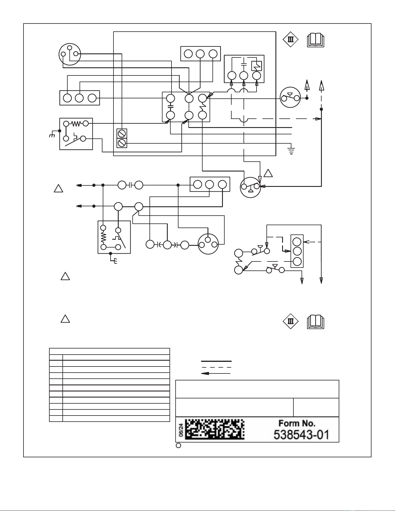
49-5000962 Rev. 0 33
FIGURE 19. Typical Field Wiring – -041, -047, -059 Units Only
Supersedes
Litho U.S.A.
C
1
GROUND
LUG
S4
HIGH
PRESSURE
SWITCH
NOTE-
FOR USE WITH COPPER CONDUCTORS
ONLY. REFER TO UNIT RATING PLATE
FOR MINIMUM CIRCUIT AMPACITY AND
MAXIMUM OVERCURRENT PROTECTION SIZE
L1
1
F
C
H
2
31
R
S
C
GREEN
RED
RED
RED
YELLOW
OUTDOOR
FAN
BLACK
DUAL
CAPACITOR
L2
L1
GROUND
TO 24 VAC POWER
SOURCE
20 VA MINIMUM
NEC CLASS 2
C
Y1
A4
TIMED OFF
CONTROL
COMPRESSOR
CONTACTOR
COMPRESSOR
CRANKCASE
HEATER
K1-1
L2
208-230/ 60/
1
BLACK
YELLOW
RED
ORANGE
RED
BLACK
H
C
F
B4
C12
CS
R
B1
A4
CONTROL-TIMED OFF
KEY
COMPONENT
B1
B4
DESCRIPTION
C12
HR1
K1,-1
S4
S24
S40
S87
COMPRESSOR
MOTOR-OUTDOOR FAN
CAPACITOR-DUAL
HEATER-COMPRESSOR
CONTACTOR-COMPRESSOR
SWITCH-HIGH PRESSURE
SWITCH-LOSS OF CHARGE
TERMOSTAT-CRANKCASE
SWITCH-LOW PRESS, COMP 1
RED
2011
2
3
1
S4
K1
A4
TO 24 VAC
POWER SOURCE
20 VA MINIMUM
NEC CLASS 2
SINGLE SPEED COOLING MODELS
S87
C
Y1
YELLOW
2
YELLOW
BLACK
IF USING A4: CONNECT S4 TO TERMINAL 3 ON A4,
CONNECT Y1 TO TERMINAL 2 ON A4
2
S87
S40
BLACK
BLACK
208-230/ 60/1
NOTE-
IF ANY WIRE IN THIS APPLIANCE IS REPLACED, IT
MUST BE REPLACED WITH WIRE OF LIKE SIZE,
RATING, INSULATION THICKNESS, AND TERMINATION.
LINE VOLTAGE FIELD INSTALLED
CLASS II VOLTAGE FIELD WIRING
DENOTES OPTIONAL COMPONENTS
S40
CRANKCASE
HEATER
BLK
BLK
HR1

34 49-5000962 Rev. 0
NOTE – The thermostat used may be electromechanical or
electronic.
NOTE – Transformer in indoor unit supplies power (24 VAC)
to the thermostat and outdoor unit controls.
COOLING:
1. Cooling demand initiates at Y1 in the thermostat.
2. 24VAC from indoor unit (Y1) energizes the TOC timed off
FRQWUROLIXVHGZKLFKHQHUJL]HVFRQWDFWRU.SURYLGHG
S4 high pressure switch is closed).
. 12 FORVHV HQHUJL]LQJ FRPSUHVVRU % DQG
outdoor fan motor (B4).
4. Compressor (B1) and outdoor fan motor (B4) begin
immediate operation.
END OF COOLING DEMAND:
5. Cooling demand is satisfied. Terminal Y1 is de-energized.
&RPSUHVVRUFRQWDFWRU.LVGHHQHUJL]HG
.RSHQVDQGFRPSUHVVRU%DQGRXWGRRUIDQPRWRU
(B4) are de-energized and stop immediately.
If the outdoor unit is void of refrigerant, clean the system
using the procedure described below.
1 - Leak test the system using the procedure outlined on
Page 24.
2 - Evacuate the system using procedure outlined on Page
25.
3 - Use nitrogen to break the vacuum and install a new filter
drier in the system.
4 - Evacuate the system again using procedure outlined on
Page 25.
5 - Weigh in refrigerant.
Servicing Units Delivered Void of Charge
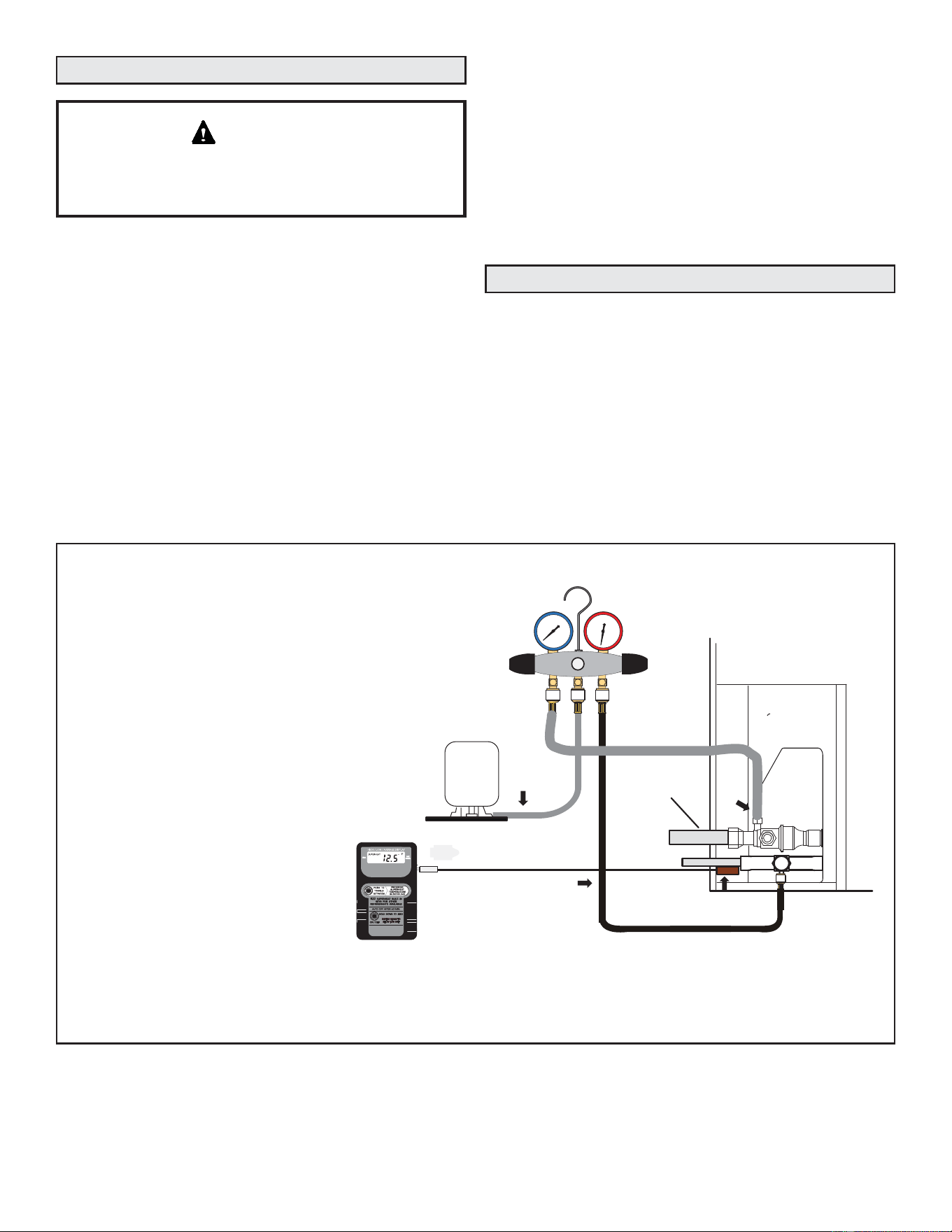
49-5000962 Rev. 0 35
Unit Start-Up
System Refrigerant
If unit is equipped with a crankcase heater, it should
be energized 24 hours before unit start-up to prevent
compressor damage as a result of slugging.
IMPORTANT
1 - Rotate fan to check for binding.
2 - Inspect all factory- and field-installed wiring for loose
connections.
3 - After evacuation is complete, open both the liquid and
vapor line service valves to release the refrigerant charge
(contained in outdoor unit) into the system.
4 - Replace the stem caps and tighten to the value listed in
TABLE 2.
5 - Check voltage supply at the disconnect switch. The
voltage must be within the range listed on the unit’s
nameplate. If not, do not start the equipment until you
have consulted with the power company and the voltage
condition has been corrected.
6 - Connect manifold gauge set for testing and charging.
This section outlines procedures for:
1 - Connecting gauge set for testing and charging;
2 - Checking and adjusting indoor airflow;
3 - Adding or removing refrigerant.
NOTE - System fault and lockout codes take precedence
over system status codes (cooling, heating operating
percentages or defrost/dehumidification).
R-454B is a zeotropic blend; will need to use saturated liquid
temperature to calculate liquid subcooling . Charge unit with
liquid only.
7 - Set the thermostat for a cooling demand. Turn on power
to the indoor unit and close the outdoor unit disconnect
switch to start the unit.
8 - Recheck voltage while the unit is running. Power must be
within range shown on the nameplate.
9 - Check system for sufficient refrigerant by using the
procedures that follow.
10 - Test functionality of refrigerant detection system. See
page 39.
FIGURE 20. Gauge Set Setup and Connections
TO LIQUID
LINE SERVICE
PORT
TEMPERATURE
SENSOR
DIGITAL SCALE
REFRIGERANT TANK
TEMPERATURE SENSOR
(LIQUID LINE)
MANIFOLD GAUGE SET
A. CLOSE MANIFOLD GAUGE SET VALVES AND CONNECT THE CENTER HOSE TO A CYLINDER OF R-454B SET FOR LIQUID PHASE CHARGING.
B. CONNECT THE MANIFOLD GAUGE SET'S LOW PRESSURE SIDE TO THE SUCTION LINE SERVICE PORT.
C. CONNECT THE MANIFOLD GAUGE SET'S HIGH PRESSURE SIDE TO THE LIQUID LINE SERVICE PORT.
D. POSITION TEMPERATURE SENSOR ON LIQUID LINE NEAR LIQUID LINE SERVICE PORT.
OUTDOOR UNIT
CHARGE IN
LIQUID PHASE
CONNECTIONS FOR TESTING AND CHARGING
GAUGE SET
A
C
D
LOW
HIGH
B
SUCTION LINE
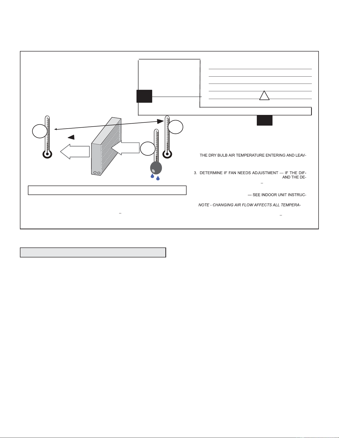
36 49-5000962 Rev. 0
ADDING OR REMOVING REFRIGERANT
This system uses R-454B which operates at slightly lower pressures than HFC-410A. The field-installed liquid line filter drier
is approved for use with R-454B. Do not replace any components designed for use with HCFC-22. Check airflow using the
Delta-T (DT) process using the illustration in FIGURE 21.
FIGURE 21. Checking Indoor Airflow over Evaporator Coil using Delta-T Chart
Cº T
DROP
–DT=ºFACTION
53º 19 – 15 = 4 INCREASE THE AIRFLOW
58º 14 – 15 = -1 (WITHIN +3º RANGE) NO CHANGE
62º 10 – 15 = -5 DECREASE THE AIRFLOW
DT
80 24 24 24 23 23 22 22 22 20 19 18 17 16 15
78 23 23 23 22 22 21 21 20 19 18 17 16 15 14
76 22 22 22 21 21 20 19 19 18 17 16 15 14 13
74 21 21 21 20 19 19 18 17 16 16 15 14 13 12
72 20 20 19 18 17 17 16 15 15 14 13 12 11 10
70 19 19 18 18 17 17 16 15 15 14 13 12 11 10
57 58 59 60 61 62 63 64 65 66 67 68 69 70
TEMPERATURE OF AIR
ENTERING INDOOR COIL ºF
INDOOR
COIL
DRY BULB
DRY
BULB
WET
BULB
B
T
DROP
19º
A
DRY-BULB
WET-BULB ºF
A
72º
B
64º
C
53º
AIR
FLOW
AIR
FLOW
ALL TEMPERATURES ARE
EXPRESSED IN ºF
1. DETERMINE THE DESIRED DT — MEASURE ENTERING AIR
TEMPERATURE USING DRY BULB (A) AND WET BULB (B).
DT IS THE INTERSECTING VALUE OF A AND B IN THE
TABLE (SEE TRIANGLE).
2. FIND TEMPERATURE DROP ACROSS COIL — MEASURE
ING THE COIL (A AND C). TEMPERATURE DROP FORMULA:
(T
DROP
) = A MINUS C.
FERENCE BETWEEN THE MEASURED T
DROP
SIRED DT (T
DROP
–DT) IS WITHIN +3º, NO ADJUSTMENT IS
NEEDED. SEE EXAMPLE AT LEFT:
4. ADJUST THE FAN SPEED
TIONS TO INCREASE/DECREASE FAN SPEED.
ASSUME DT = 15 AND A TEMP. = 72º, BELOW C TEMPERATURES REQUIRE ACTION:
AIRFLOW
INDOOR COIL
TURES; RECHECK TEMPERATURES TO CONFIRM THAT THE
TEMPERATURE DROP AND DT ARE WITHIN +
3º.
Verify the unit is electrically grounded before charging
the system. Extreme care shall be taken not to overfill the
refrigerating system.
Charge should be checked and adjusted using information
outlined in this section and in the tables provided on the
charging label on the unit’s control access panel.
R-454B is a zeotropic blend of two refrigerants. At any
given refrigerant pressure, R-454B will have two saturation
temperatures, a saturated liquid temperature and a saturated
vapor temperature. See R-454B Refrigerant Pressure
Temperature Chart in the installation and service manual
for saturation temperatures.
R-454B Units must be charged with liquid refrigerant. Follow
conventional charging procedures when charging the
system. The technician is required to mark the total charge
of the installed system on the unit nameplate, which includes
the nameplate charge (factory charge) and additional charge
that is added to the system at the time of installation.
7KH5%UHIULJHUDQWF\OLQGHUVDUHSURYLGHGZLWKDóފ/+
IODUHFRQQHFWLRQWKHUHIRUHDóފ/+IHPDOHIODUHDGDSWHUZLOO
be required. Connect manifold gauges and hoses following
conventional charging procedures. Position the R-454B
refrigerant cylinder to deliver liquid refrigerant.
NS16A unit is factory-charged with enough R-454B
refrigerant to accommodate a 15-foot length of refrigerant
piping. For line lengths over 15 feet, add 3 oz of refrigerant
for every 5 feet of piping beyond 15 feet.
Initiate a call for cooling and allow the refrigerant pressures
and temperatures to stabilize. Adjust the charge using the
subcooling method. The unit charging label provides the
target Subcooling Values. Record the liquid line temperature.
Measure the liquid line pressure and use the value to
determine the Saturated Liquid Temperature. Calculate
subcooling by subtracting the liquid line temperature from
the Saturated liquid temperature.
Subcooling = Saturated Liquid Temperature – Liquid
Line Temperature
Compare the results with the unit charging label.
Once system charging has been completed, the additional
charge and total charge must be marked on the unit
nameplate. Total Charge = Factory Charge + Additional
charge. The total charge is marked on the space adjacent to
“Total Charge”. See nameplate on Page 37.
Charging
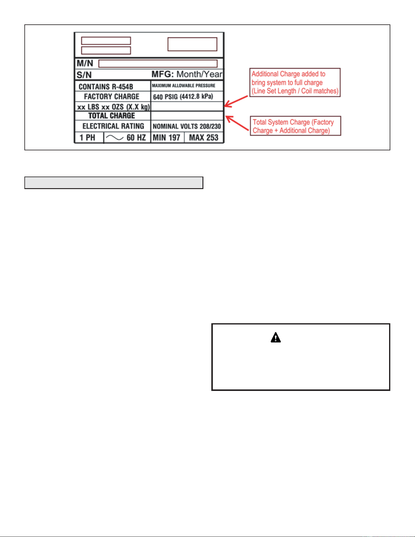
49-5000962 Rev. 0 37
NOTE - The nameplate is shown for illustration purposes only. Go to actual nameplate on outdoor unit for charge
information.
Before carrying out this procedure, it is essential that the
technician is completely familiar with the equipment and all its
detail. It is recommended good practice that all refrigerants
are recovered safely.
Prior to the task being carried out, an oil and refrigerant
sample shall be taken in case analysis is required prior to
re-use of recovered refrigerant. It is essential that electrical
power is available before starting decommissioning.
a) Become familiar with the equipment and its operation.
b) Isolate system electrically.
c) Before attempting the procedure, ensure that:
• mechanical handling equipment is available, if required,
for handling refrigerant cylinders;
• all personal protective equipment is available and being
used correctly;
• the recovery process is supervised at all times by a
competent person;
• recovery equipment and cylinders conform to the
appropriate standards.
d) Pump down refrigerant system, if possible.
e) If a vacuum is not possible, make a manifold so that
refrigerant can be removed from various parts of the
system.
f) Make sure that cylinder is situated on the scales before
recovery takes place.
g) Start the recovery machine and operate in accordance
with instructions.
h) Do not overfill cylinders (no more than 80% volume liquid
charge).
i) Do not exceed the maximum working pressure of the
cylinder, even temporarily.
j) When the cylinders have been filled correctly and the
process completed, make sure that the cylinders and the
equipment are removed from site promptly and all isolation
valves on the equipment are closed off.
k) Recovered refrigerant shall not be charged into another
REFRIGERATING SYSTEM unless it has been cleaned
and checked.
Decommissioning
Equipment shall be labelled stating that it has been
decommissioned and emptied of refrigerant. The label
shall be signed and dated. Ensure that there are labels on
WKHHTXLSPHQWWKDWVWDWHWKHÀDPPDELOLW\RIWKHUHIULJHUDQW
used.
IMPORTANT

38 49-5000962 Rev. 0
Pressure
(psig)
Saturated
Liquid
Temp (°F)
Saturated
Vapor
Temp (°F)
Pressure
(psig)
Saturated
Liquid
Temp (°F)
Saturated
Vapor
Temp (°F)
Pressure
(psig)
Saturated
Liquid
Temp (°F)
Saturated
Vapor
Temp (°F)
Pressure
(psig)
Saturated
Liquid
Temp (°F)
Saturated
Vapor
Temp (°F)
0 -58.9 -57.1 158 58.9 61.3 272 93 95.4 362 113.4 115.6
25 -19.2 -17.2 160 59.6 62 274 93.5 95.9 364 113.8 116
30 -13.9 -11.8 165 61.4 63.8 276 94 96.4 366 114.2 116.4
35 -9.0 -6.9 170 63.1 65.5 278 94.5 96.9 368 114.6 116.8
40 -4.4 -2.3 175 64.9 67.3 280 95 97.4 370 115 117.2
45 -0.2 1.9 180 66.6 69 282 95.5 97.9 372 115.4 117.6
50 3.7 5.9 185 68.2 70.6 284 96 98.4 374 115.8 118
55 7.5 9.7 190 69.8 72.2 286 96.5 98.8 376 116.2 118.4
60 11 13.2 195 71.4 73.8
288 97 99.3 378 116.6 118.8
65 14.4 16.6 200 73 75.4 290 97.5 99.8 380 117 119.2
70 17.6 19.8 202 73.6 76 292 97.9 100.3 382 117.4 119.6
75 20.6 22.9 204 74.2 76.6 294 98.4 100.7 384 117.7 119.9
80 23.6 25.9 206 74.9 77.3 296 98.9 101.2 386 118.1 120.3
85 26.4 28.7 208 75.5 77.9 298 99.4 101.7 388 118.5 120.7
90 29.1 31.4 210 76.1 78.5 300 99.8 102.2 390 118.9 121.1
95 31.7 34 212 76.7 79.1 302 100.3 102.6 392 119.3 121.5
100 34.3 36.6 214 77.3 79.7 304 100.8 103.1 394 119.7 121.9
102 35.3 37.6 216 77.9 80.2 306 101.2 103.5 396 120.1 122.2
104 36.2 38.6 218 78.4 80.8 308 101.7 104 398 120.5 122.6
106 37.2 39.5 220 79 81.4 310 102.1
104.4 400 120.8 123
108 38.1 40.5 222 79.6 82 312 102.6 104.9 405 121.8 123.9
110 39.1 41.4 224 80.2 82.6 314 103 105.4 410 122.7 124.9
112 40 42.4 226 80.8 83.1 316 103.5 105.8 415 123.6 125.8
114 40.9 43.3 228 81.3 83.7 318 103.9 106.2 420 124.6 126.7
116 41.8 44.2 230 81.9 84.3 320 104.4 106.7 425 125.5 127.6
118 42.7 45.1 232 82.4 84.8 322 104.8 107.1 430 126.4 128.5
120 43.6 46 234 83 85.4 324 105.3 107.6 435 127.3 129.4
122 44.5 46.9 236 83.6 86 326 105.7 108 440 128.2 130.2
124 45.4 47.7 238 84.1 86.5 328 106.2 108.5 445 129 131.1
126 46.2 48.6 240 84.7 87.1 330 106.6 108.9 450 129.9 132
128 47.1 49.4 242 85.2 87.6 332 107 109.3 460
131.6 133.7
130 47.9 50.3 244 85.8 88.1 334 107.5 109.7 470 133.3 135.3
132 48.8 51.1 246 86.3 88.7 336 107.9 110.2 480 135 137
134 49.6 51.9 248 86.8 89.2 338 108.3 110.6 490 136.7 138.6
136 50.4 52.8 250 87.4 89.7 340 108.8 111 500 138.3 140.2
138 51.2 53.6 252 87.9 90.3 342 109.2 111.5 510 139.9 141.8
140 52 54.4 254 88.4 90.8 344 109.6 111.9 520 141.5 143.3
142 52.8 55.2 256 88.9 91.3 346 110 112.3 530 143 144.8
144 53.6 56 258 89.5 91.8 348 110.5 112.7 540 144.5 146.3
146 54.3 56.7 260 90 92.4 350 110.9 113.1 550 146.1 147.8
148 55.1 57.5 262 90.5 92.9 352 111.3 113.5 560 147.5 149.2
150 55.9 58.3 264 91 93.4 354 111.7 114 570 149 150.7
152 56.6 59 266 91.5 93.9 356 112.1 114.4 580 150.5 152.1
154 57.4 59.8 268 92 94.4 358 112.5 114.8 590 151.9 153.5
156 58.1 60.5 270 92.5 94.9 360 112.9 115.2 600 153.3 154.8
TABLE 4. R-454B Temperature – Pressure (Psig)
R-454B Refrigerant Pressure-Temperature Chart
Notes:
1. R-454B is a zeotropic blend and must be charged with liquid refrigerant only.
2. Saturated liquid temperature is used to calculate liquid subcooling.
3. Saturated vapor temperature is used to to calculate suction superheat.
4. See unit charging label for subcooling values and additional charging information.
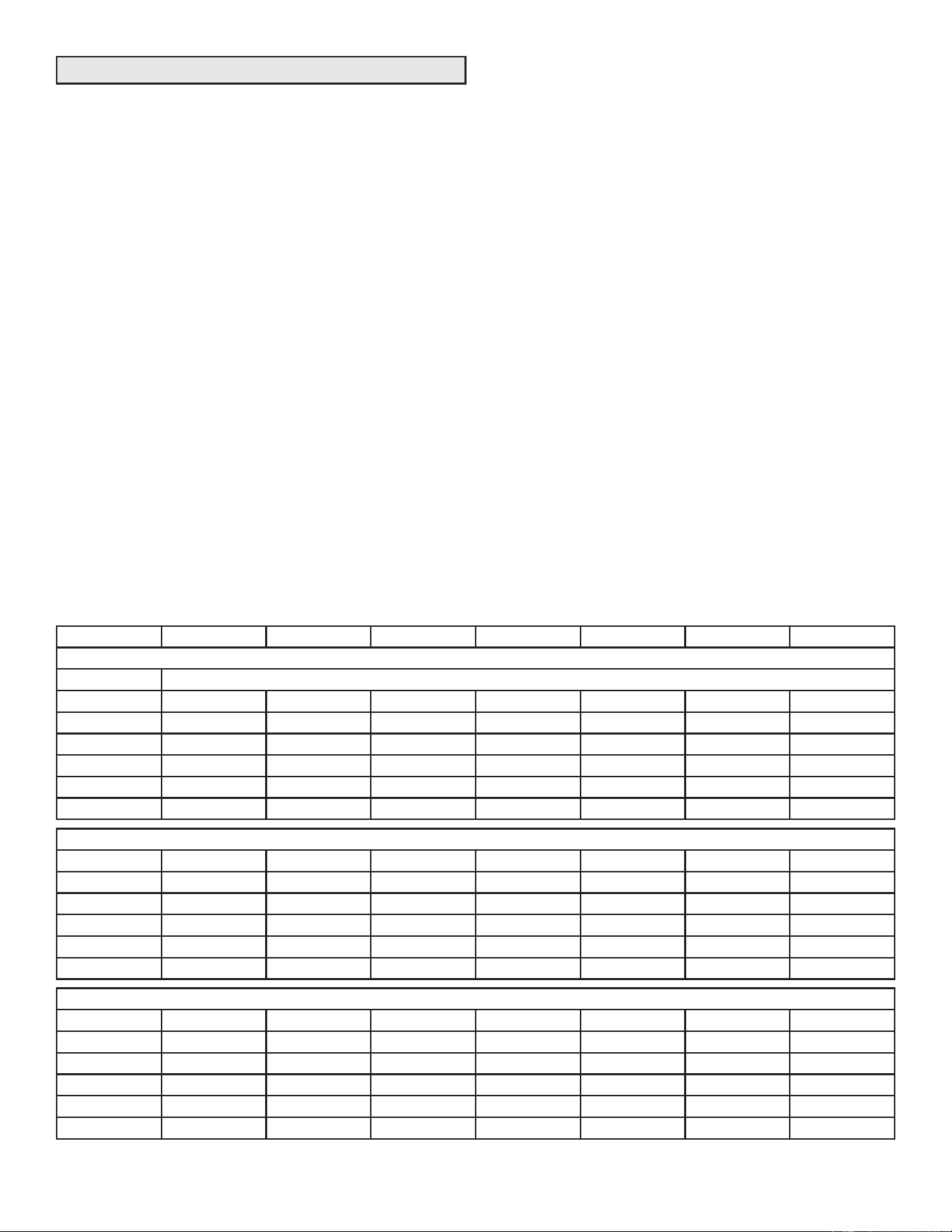
49-5000962 Rev. 0 39
The RDS Blower Control Board is equipped with a Test/
Reset button. After the RDS Blower Control Board has been
mounted and wired, restore power to the HVAC system. The
system will then run through a purge sequence for five (5)
minutes. After the purge sequence is complete, proceed to
testing cooling demand and heating demand.
Cooling Demand
1 - Prompt a cooling demand at the thermostat.
2 - Press the Test button on the RDS Blower Control Board.
The system then executes a leak detection response.
3 - Observe the following sequence:
a. The LED indicator flashes the sequence for leak
detection (flashing blue).
b. The blower powers up.
c. The outdoor compressor powers down.
4 - Press the Test button to terminate the simulated Leak
Detected mode upon test completion.
Heating Demand
1 - Prompt a heating demand at the thermostat.
2 - Press the Test button on the RDS Blower Control Board.
The system then executes a leak detection response.
3 - Observe the following sequence:
a. The LED indicator flashes the sequence for leak
detection (flashing blue).
b. The blower powers up.
c. The gas burners power down.
d. The outdoor compressor powers down.
4 - Press the Test button to terminate the simulated Leak
Detected mode upon test completion.
The installation of the RDS Blower Control Board is complete
after both sequences are successfully completed
Start-Up Test Procedure
Charging Procedures
AIR CONDITIONER CHARGING INFORMATION
For complete charging procedures, refer to the applicable installation manual available online
Capacity -18 -24 -30 -36 -42 -48 -60
Normal Operating Pressures¹
°F(°C)² TXV System – Liquid Line ( ± 10 psig) / Suction Line ( ± 5 psig)
65 (18) 211 / 131 213 / 127 210 / 123 217 / 116 214 / 124 221 / 113 211 / 120
75 (24) 243 / 133 246 / 130 242 / 127 251 / 124 247 / 131 257 / 122 244 / 123
85 (29) 283 / 135 286 / 132 283 / 129 292 / 128 287 / 133 296 / 126 286 / 125
95 (35) 326 / 138 331 / 134 326 / 131 336 / 133 330 / 135 341 / 130 332 / 126
105 (41) 374 / 139 381 / 136 375 / 133 384 / 136 378 / 137 390 / 132 381 / 128
115 (45) 426 / 141 435 / 138 427 / 135 436 / 138 431 / 139 444 / 133 434 / 130
Approach (APP) Values³ – ºF(ºC) ± 1ºF (0.5ºC)
65 (18) 3 (-16.1) 3 (-16.1) 1 (-17.2) 1 (-17.2) 2 (-16.7) 3 (-16.1) 2 (-16.7)
75 (24) 4 (-15.6) 4 (-15.6) 3 (-16.1) 2 (-16.7) 5 (-15.0) 4 (-15.6) 4 (-15.6)
85 (29) 4 (-15.6) 4 (-15.6) 4 (-15.6) 3 (-16.1) 5 (-15.0) 5 (-15.0) 4 (-15.6)
95 (35) 5 (-15.0) 4 (-15.6) 4 (-15.6) 4 (-15.6) 5 (-15.0) 6 (-14.4) 4 (-15.6)
105 (41) 4 (-15.6) 4 (-15.6) 4 (-15.6) 5 (-15.0) 5 (-15.0) 6 (-14.4) 4 (-15.6)
115 (45) 3 (-16.1) 4 (-15.6) 4 (-15.6) 6 (-14.4) 5 (-15.0) 6 (-14.4) 4 (-15.6)
6XEFRROLQJ6&9DOXHV7;96\VWHP)&)&
65 (18) 9 (-12.8) 9 (-12.8) 10 (-12.2) 12 (-11.1) 10 (-12.2) 12 (-11.1) 11 (-11.7)
75 (24) 6 (-14.4) 7 (-13.9) 7 (-13.9) 10 (-12.2) 7 (-13.9) 10 (-12.2) 8 (-13.3)
85 (29) 7 (-13.9) 7 (-13.9) 7 (-13.9) 10 (-12.2) 6 (-14.4) 9 (-12.8) 8 (-13.3)
95 (35) 6 (-14.4) 7 (-13.9) 7 (-13.9) 9 (-12.8) 7 (-13.9) 8 (-13.3) 8 (-13.3)
105 (41) 7 (-13.9) 8 (-13.3) 7 (-13.9) 8 (-13.3) 7 (-13.9) 8 (-13.3) 9 (-12.8)
115 (45) 7 (-13.9) 8 (-13.3) 6 (-14.4) 7 (-13.9) 6 (-14.4) 8 (-13.3) 8 (-13.3)
¹ Typical pressures; indoor evaporator match-up, indoor air quantity and evaporator load will cause
the pressures to vary.
² Temperature of air entering outside coil.
³ Approach = Liquid Line Temperature minus Outdoor Ambient Temperature.
6XEFRROLQJ 6DWXUDWHG/LTXLG7HPSHUDWXUHPLQXV/LTXLG/LQH7HPSHUDWXUH
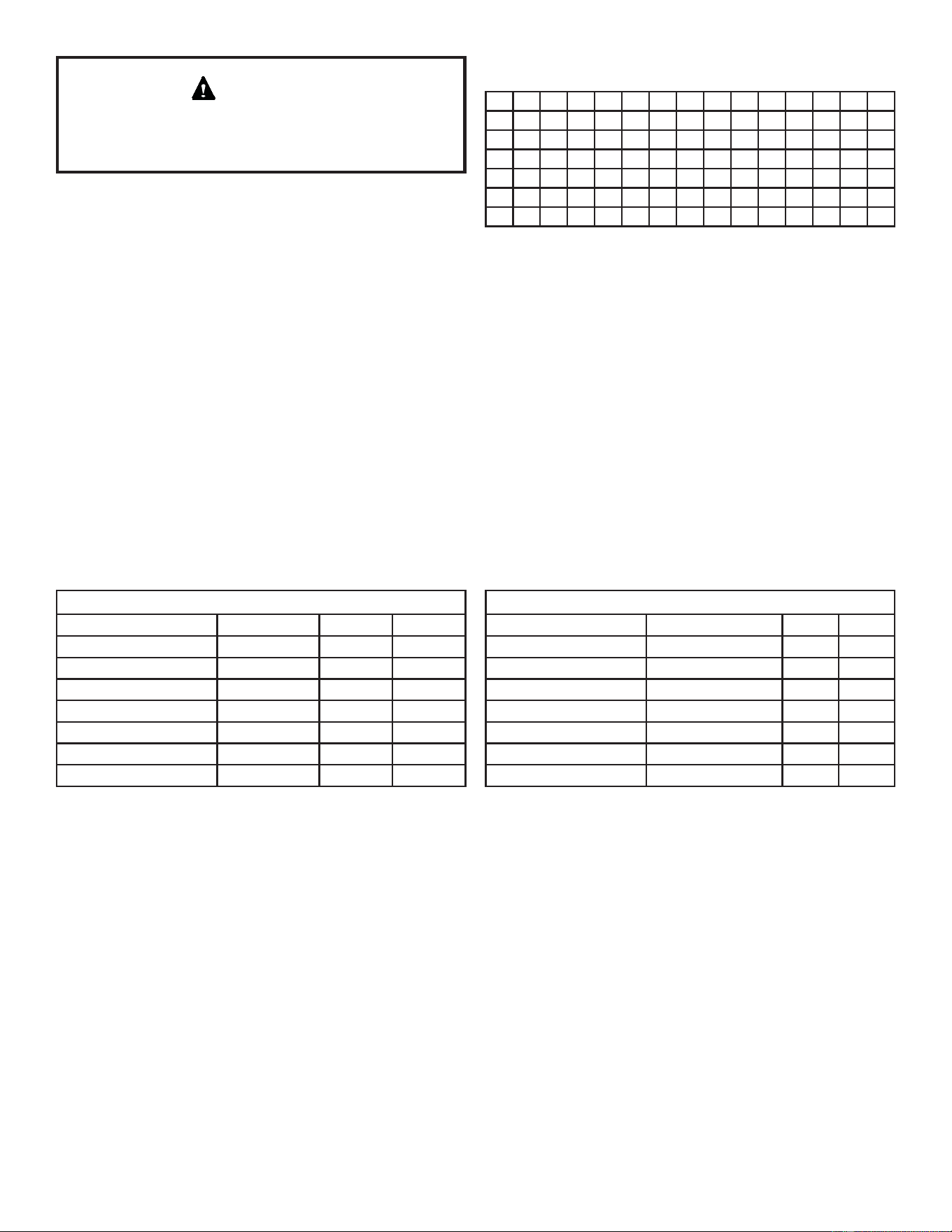
40 49-5000962 Rev. 0
R-454B is a zeotropic blend. Use saturated liquid
temperature to calculate liquid subcooling. Charge unit
with liquid only.
IMPORTANT
AIRFLOW CHECK - Both airflow and refrigerant charge
must be monitored for proper system set-up. It may be
necessary to alternately check and adjust the airflow and
the refrigerant charge.
NOTE – Be sure that filters and indoor and outdoor coils are
clean before testing.
To determine temperature drop across indoor coil (Delta-T),
measure the entering air dry bulb (DB) and wet bulb (WB)
temperatures at the indoor coil. Find Delta-T in table 4.
Measure coil’s leaving air DB and subtract that value from
entering air DB. The measured difference should be within
±3°F (±1.8°C) of table value: if too low, decrease the indoor
fan speed (refer to indoor unit for information). If the Delta-T
is too high, increase the indoor fan speed. Repeat charging
procedure and Delta-T (air flow adjustment) procedure until
both are correct.
Example: Assume entering air DB - 72, WB - 64, leaving
DB - 53. Therefore, Delta-T should be 15 (per table); delta
across coil is 72 - 53 or 19 (which is 4ºF higher than table
value). Action necessary: increase fan speed.
80 24 24 24 23 23 22 22 22 20 19 18 17 16 15
78 23 23 23 22 22 21 21 20 19 18 17 16 15 14
76 22 22 22 21 21 20 19 19 18 17 16 15 14 13
74 21 21 21 20 19 19 18 17 16 16 15 14 13 12
72 20 20 19 18 17 17 16 15 15 14 13 12 11 10
70 19 19 18 18 17 17 16 15 15 14 13 12 11 10
ºF 57 58 59 60 61 62 63 64 65 66 67 68 69 70
Table 4. Evaporator Coil Delta-T
Dry bulb temperature of air entering indoor coil (°F)
[ Wet bulb temperature of air entering indoor coil ]
0RWRU:LQGLQJ5HVLVWDQFHȍ
Unit Model Number Compressor C-S C-R
NS16A18 <3+.$$ 1.68 1.21
NS16A24 <3+.$$ 1.41 1.59
NS16A30 <3+.$$ 1.06 1.63
NS16A36 <3+.$$ 0.87 1.3
NS16A42 <3+.$$ 0.75 1.75
NS16A48 <%+.$$ 0.58 0.71
NS16A60 <%+.$$ 0.47 0.78
0RWRU:LQGLQJ5HVLVWDQFHȍ
Unit Model Number Compressor C-S C-R
NS16A18 <$.(3)9$6( 1.54 1.37
NS16A24 <$.(3)9$6( 1.26 1.37
NS16A30 <$.(3)9$6( 0.89 1.57
NS16A36 <$.(3)9$6( 0.72 1.43
NS16A42 <$.(3)9$6& 0.52 1.6
NS16A48 <$.(3)9$6& 0.46 1.3
NS16A60 <$.(3)9$6& 0.39 0.78