Rev.25.08
Owner: Please retain these instructions for future reference.
For residential use only.
Installer: Please leave these instructions with this unit for the owner.
Important: Read and save these isntructions.
User & Installation
Manual
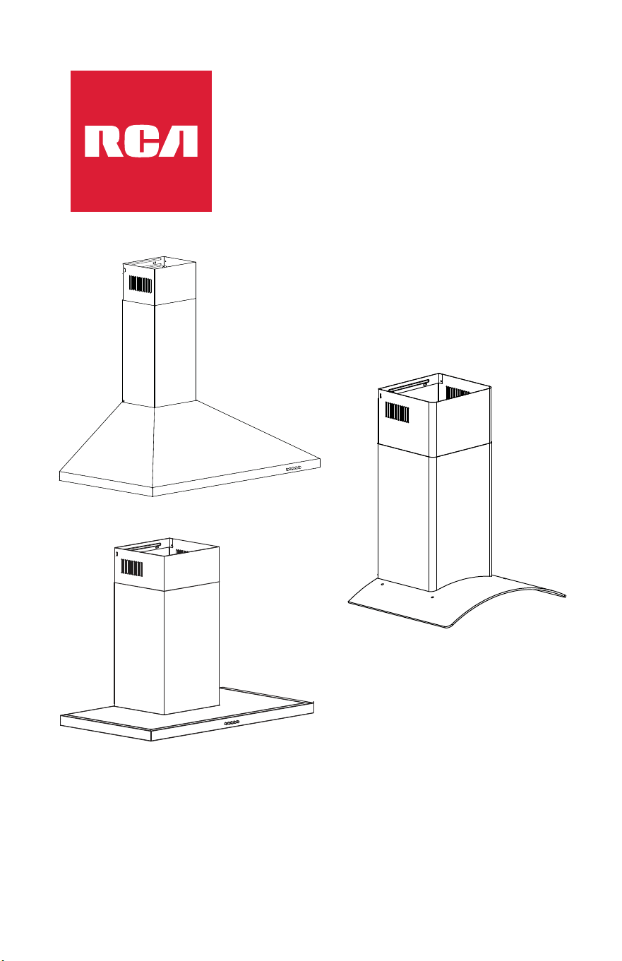
Wall Mount Range Hood
R-RHWM1H30BSS
R-RHWM2R30BSS
R-RHWM3S30BSS

Thank you for your purchase. We know that you have many brands and
products to choose from and we are honored to know that you have decided
to take one of our products into your home and hope that you enjoy it.
RCA
Appliances are designed according to the strictest safety and
performance standard for the North American market. We follow the most
advanced manufacturing philosophy. Each appliance leaves the factory after
thorough quality inspection and testing. Our distributors and our service
partners are ready to answer any questions you may have regarding how to
install, use and case for your products. We hope that this manual will help you
learn to use the product in the safest and most effective manner.
Before using this product, please read through this manual carefully. Keep
this user manual in a safe place for future reference. Please ensure that other
persons using this product are familiar with these instructions as well.
If you have any questions or concerns, please contact the dealer from whom
you purchased the product, or contact our Customer Support at:
1-626-800-4288
Reach us online at: fgsbrands.com/rca-help
Thank You For Your Purchase
2

Table of Contents
3
RANGE HOOD SAFETY .......................................................................................... 4
Important Safety Instructions .................................................................................. 5
INSTALLATION REQUIREMENTS ........................................................................... 7
Tools and Parts ......................................................................................................... 7
Location Requirements............................................................................................ 9
Product Dimensions .............................................................................................. 10
Cabinet Clearances................................................................................................ 13
Venting Requirements ........................................................................................... 14
Electrical Requirements ......................................................................................... 18
INSTALLATION INSTRUCTIONS .......................................................................... 19
Prepare Location .................................................................................................... ...25
Install Range Hood .................................................................................................... 34
Complete Installation ............................................................................................... 36
RANGE HOOD USE .............................................................................................. 37
Controls .................................................................................................................. 37
RANGE HOOD CARE ................................................................................................ 39
Cleaning ...................................................................................................................... 39
Replacing the LED Light ........................................................................................ ...41
LIMITED WARRANTY ................................................................................................43
Replacing the Charcoal Filter ................................................................................... .40
Your safety and the safety of others are very important.
We have provided many important safety messages in this manual and on
your appliance. Always read and obey all safety messages.
This is the safety alert symbol.
This symbol alerts you to potential hazards that
can kill or hurt you and others.
All safety messages will follow the safety alert
symbol and either the word "WARNING" or
"CAUTION." These words mean:
You can be killed or seriously injured if you
don't follow instructions.
WARNING
A potentially hazardous situation which, if not
avoided, could result in minor or moderate
injury.
CAUTION
All safety messages will tell you what the potential hazard is, tell you how to
reduce the chance of injury, and tell you what can happen if the instructions
are not followed.
California Proposition 65 Warning
WARNING: Cancer and Reproductive Harm www.P65Warnings.ca.gov.
WARNING: This appliance is intended for normal indoor residential use. It is
not approved for commercial use, outdoor installation, installation over an
outdoor BBQ grill, or any other application not specifically allowed by this
manual. Damage from improper installation or use of this appliance is not
covered by the product warranty.
Range Hood Safety
WARNING
4
Important Safety Instructions
WARNING: To reduce the risk of fire, electrical shock, injury to persons,
or damage when using the cooktop, follow basic precautions, including
the following:
•Use this unit only in the manner
intended by the manufacturer. If
you have questions, contact the
manufacturer.
•Before servicing or cleaning
the unit, switch the power off at
the service panel and lock the
service panel to prevent power
from being switched on
accidentally. When the service
disconnecting means cannot be
locked, securely fasten a
prominent warning device, such
as a tag to the service panel.
•Installation work and electrical
wiring must be done by qualified
person(s) in accordance with all
applicable codes and standards,
including fire-rated construction.
•Do not operate any fan with a
damaged cord or plug. Discard
fan or return to an authorized
service facility for examination
and/or repair.
Ducted fans must always be
vented to the outdoors.
CAUTION: For general
ventilating use only. Do not use
to exhaust hazardous or
explosive materials and vapors.
•CAUTION: To reduce the risk of
fire and to properly exhaust air,
be sure to duct air outside - do
not vent exhaust air into spaces
within walls or ceilings, or into
attics, crawl spaces or garages.
Sufficient air is needed for
proper combustion and
exhausting of gases through the
flue (chimney) of fuel burning
equipment to prevent
backdrafting. Follow the heating
equipment manufacturer’s
guideline and safety standards
such as those published by the
National Fire Protection
Association (NFPA), the
American Society for Heating,
Refrigeration and Air
Conditioning Engineers
(ASHRAE), and the local code
authorities.
•When cutting or drilling into the
wall or ceiling; do not damage
electrical wiring and other
hidden utilities.
WARNING: TO REDUCE THE
RISK OF A RANGE TOP GREASE
FIRE:
•Never leave surface units
unattended at high settings.
Boilovers cause smoking and
greasy spillovers that may ignite.
Heat oils slowly on low or
medium settings.
5
Important Safety Instructions
• Always turn the hood ON when
cooking at high heat or when
flambéing food (i.e. Crepes
Suzette, Cherries Jubilee,
Peppercorn Beef Flambé).
•
Clean ventilating fans frequently.
Grease should not be allowed to
accumulate on the fan or filter.
• Use proper pan sizes. Always use
cookware appropriate for the size
of the surface element.
WARNING: TO REDUCE THE RISK
OF INJURY TO PERSONS IN THE
EVENT OF A RANGE TOP GREASE
FIRE, OBSERVE THE FOLLOWING:*
• SMOTHER FLAMES with a close
fitting lid, cookie sheet, or metal
tray, then turn off the burner. BE
CAREFUL TO PREVENT BURNS. If
the flames do not go out
immediately, EVACUATE AND
CALL THE FIRE DEPARTMENT.
• NEVER PICK UP A FLAMING PAN
- you may be burned
• DO NOT USE WATER, including
wet dishcloths or towels - a violent
steam explosion will result.
• Use an extinguisher ONLY if:
oYou know you have a class
ABC extinguisher, and you
already know how to
operate it.
• The fire is small and contained
in the area where it started.
•
The fire department is being
called.
• You can fight the fire with your
back to an exit.
* Based on "Kitchen Fire Safety
Tips" published by NFPA.
• WARNING: TO REDUCE THE
RISK OF FIRE, USE ONLY METAL
DUCTWORK.
• WARNING: To reduce the risk
of fire or electrical shock, do not
use this fan with any solid-state
speed control device.
• WARNING: Do not let children
near this appliance. Do not let
children play with this appliance.
Keep all packaging materials out
of children’s reach. Properly
dispose the packaging materials
after this appliance is unpacked.
• The manufacturer declines all
responsibility in the event of
failure to observe the instructions
given here for installation,
maintenance, and suitable use of
the product.
• The manufacturer further
declines all responsibility for
injury due to negligence and the
warranty of the unit automatically
expires due to improper
maintenance.
READ AND SAVE THESE INSTRUCTIONS
6

INSTALLATION INSTRUCTIONS
Tools and Parts
Gather the required tools and parts before starting installation. Read and
follow the instructions provided with any tools listed here.
Tools Needed
•Level
•Drill with 5/32" (4 mm) and 5/16" (8 mm) drill bits
•Pencil
•Tape measure or ruler
•Phillips screwdriver
•Hand gloves
Parts Needed
For ducted installations, you will need:
•Duct system
•Duct clamps or HVAC foil tape
•Caulking gun and weatherproof caulking compound
For ductless (recirculating) installations, you will need:
•Charcoal filter kit. See the "Optional Parts" section to order.
7

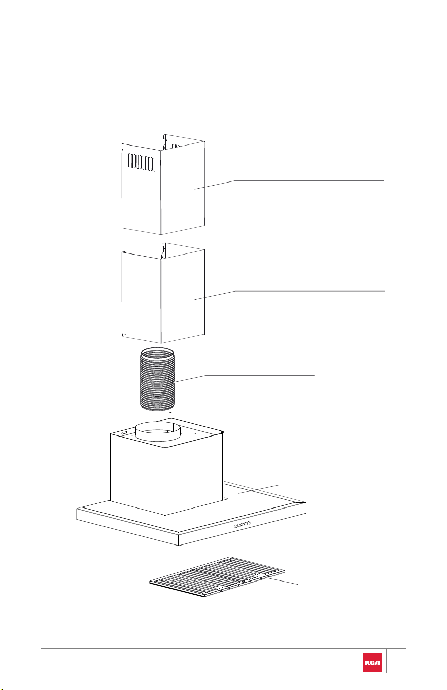
Parts Supplied
Remove parts from packages. Check that all parts are included.
•Range hood (main core) with damper, blower, and LED lights installed
•Metal baffle filters (2) for R-RHWM1H30BSS, R-RHWM3S30BSS
•Metal baffle filter (1) for R-RHWM2R30BSS
•Inner chimney (Upper vent cover) (1)
•Outer chimney (Lower vent cover) (1)
•Range hood (main core) mounting bracket (1)
•Inner chimney support bracket (1)
•Outer chimney support bracket (1)
•6" round aluminum duct (1)
•Oil tray (1) (Attached to the motor)
•4 x 40 mm mounting screws (9)
•4 x 8 mm short screws (6) for R-RHWM1H30BSS
•4 x 8 mm short screws (4) for R-RHWM2R30BSS, R-RHWM3S30BSS
•8 x 37.5 mm wall anchors (9)
Scan QR code to
purchase the
optional parts.
•CFK7 Charcoal filter kit
•Chimney (vent cover) extensions
NOTE:
•27.5" chimney extensions replace the chimneys shipped with the
range hood.
Optional Parts
To purchase these or any other accessories,
please visit: fgsbrands.com/rca-parts or reference the contact information
at the end of this manual.
8

Location Requirements
IMPORTANT:
•Observe all governing codes and ordinances.
Have a qualified technician install the range hood. It is the installer’s
responsibility to comply with installation clearances specified on the
model/serial/rating plate. The model/serial/rating plate is located inside the
range hood on the rear wall of the range hood.
Range hood location should be away from strong draft areas, such as windows,
doors, and strong heating vents.
Cabinet opening dimensions that are shown must be used. Given dimensions
provide minimum clearance.
Grounded electrical outlet is required. See the "Electrical Requirements"
section.
The range hood is factory set for venting through the roof or wall. If it is not
possible to vent cooking fumes and vapors to the outside, the range hood can
be used in the ductless (recirculating) version. Charcoal filters are required for
ductless (recirculating) installations. See "Optional Parts" in the "Tools and
Parts" section to order.
All openings in ceiling and wall where range hood will be installed must be
sealed.
For Mobile Home Installations:
The installation of this range hood must conform to the Manufactured Home
Construction Safety Standards, Title 24 CFR, Part 328 (formerly the Federal
Standard for Mobile Home Construction and Safety, Title 24, HUD, Part 280) or
when such standard is not applicable, the standard for Manufactured Home
Installation 1982 (Manufactured Home Sites, Communities and Setups) ANSI
A225.1/NFPA 501A or latest edition, or with local codes.
9
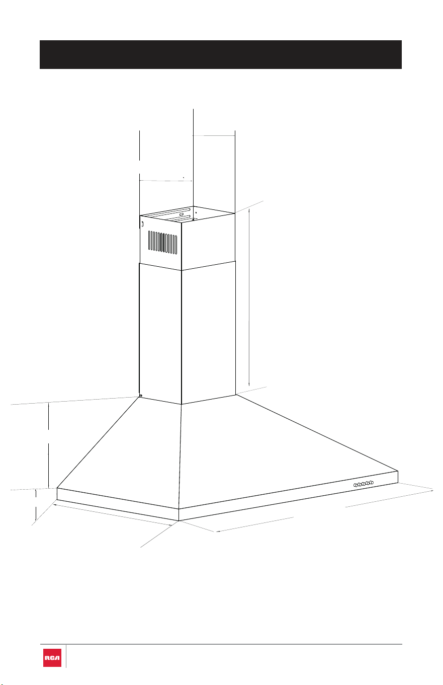
PRODUCT DIMENSIONS
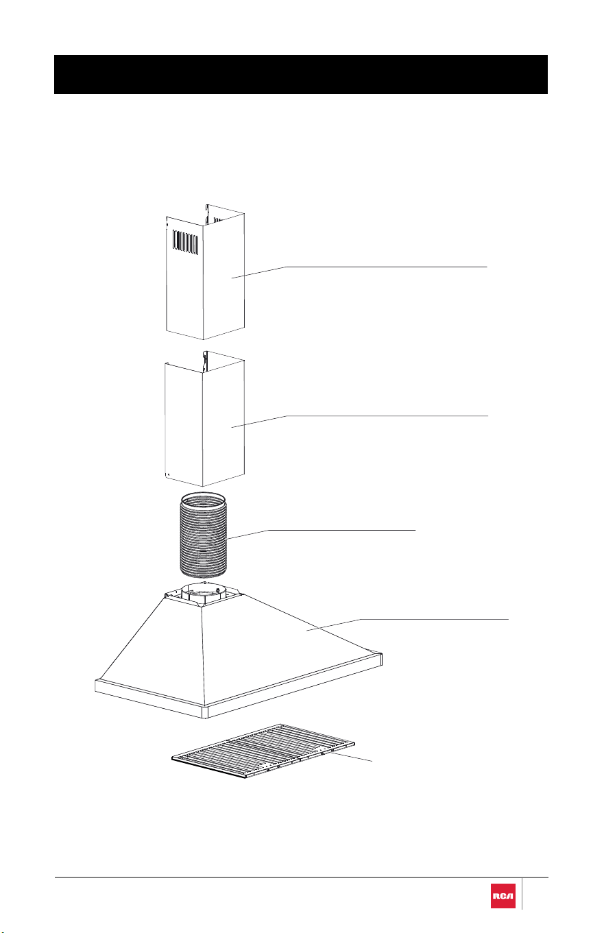
R-RHWM1H30BSS
10
6⅞" (175mm)
8⅞" (225mm)
15¾" - 30¹¹⁄₁₆" (400mm - 780mm)
8⅞" (225mm)
23⅜" (747mm)
1⅜" (35mm)
19¹¹⁄₁₆" (500mm)
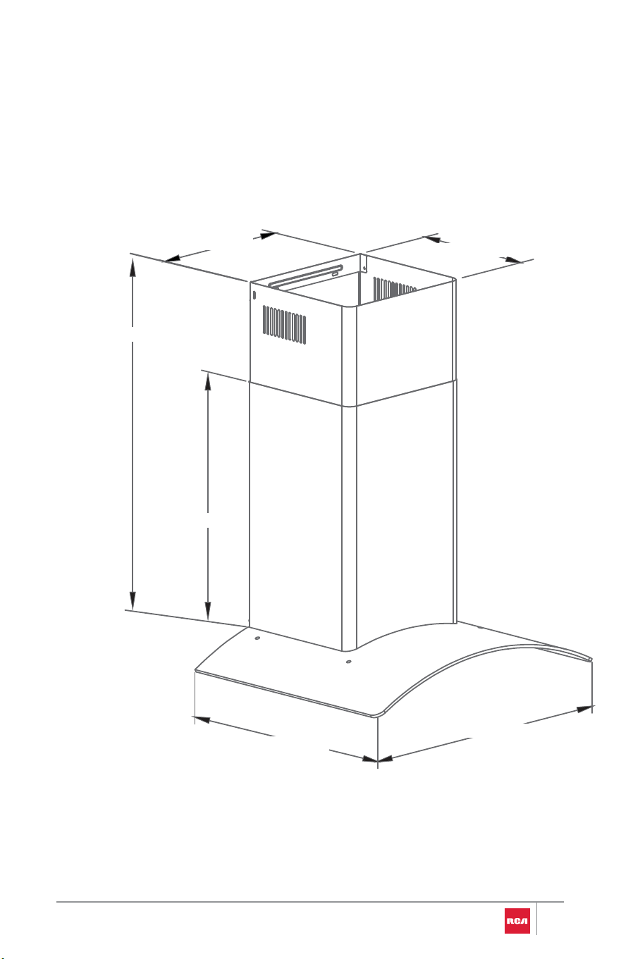
R-RHWM2R30BSS
11
15 ¾" (400mm)
18 ⅛" (460mm)
29 ½" (748mm)
15 ¾ - 30¹¹⁄₁₆" (400mm - 780mm)
11⅞" (303mm)
10¾" (273mm)
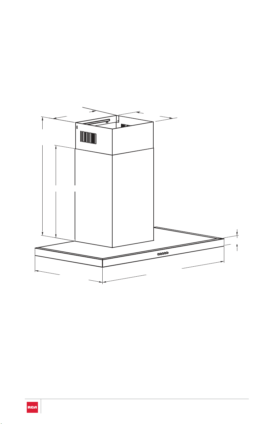
R-RHWM3S30BSS
12
29⅜" (747mm)
19¹¹⁄₁₆" (500mm)
19¹¹⁄₁₆" (500mm)
19
¹¹⁄₁₆" - 38⁹⁄₁₆"
(500mm-980mm)
1⁹⁄₁₆" (40mm)
11¹³⁄₁₆" (300mm)
10¹³⁄₁₆" (275mm)
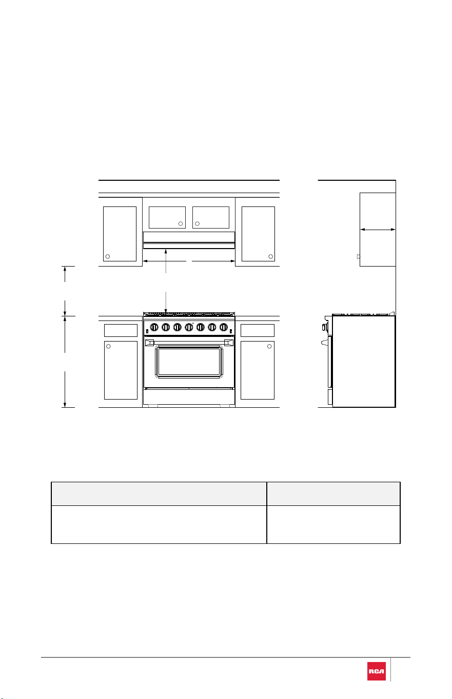
Cabinet Clearances
Given dimensions are minimum clearances.
Wall Mount Range Hood
Model A
R-RHWM1H30BSS, R-RHWM2R30BSS, R-
RHWM3S30BSS
25.6" (65 cm)
IMPORTANT:
•25.6" (65.0 cm) minimum and 36” (91.4 cm) suggested maximum
clearances between cookingsurface and bottom of the range hood.
13
12"
(30.5 cm)
Overhead
Cabinet
Depth
A
Max. 36" (91.4 cm)
Min. 25.6" (65.0 cm)
18"
(45.7 cm)
36"
(91.4 cm)

Venting Requirements
(Ducted installations only)
•Duct system must terminate to the outdoors, except for ductless
(recirculating) installations.
•Do not terminate the duct system in an attic or other enclosed area.
•Do not use 4” (10.2 cm) laundry-type wall cap.
•Use metal duct only. A rigid metal duct is recommended. Plastic or metal
foil duct is not recommended.
•The length of duct system and number of elbows should be kept to a
minimum to provide efficient performance.
For the most efficient and quiet operation:
•Use rigid metal duct.
•Use no more than three 90° elbows.
•Make sure there is a minimum of 25
9/16”
(65.0 cm) of straight duct between
the elbows if more than 1 elbow is used.
•Do not install 2 elbows together.
•Use clamps to seal all joints in the duct system.
•The duct system must have a damper. If the roof or wall cap has a damper,
do not use the damper supplied with the range hood.
•Use caulking to seal exterior wall or roof opening around the cap.
•The size of the duct should be uniform.
Cold Weather Installations:
An additional backdraft damper should be installed to minimize backward cold
air flow and a thermal break should be installed to minimize conduction of
outside temperatures as part of the duct system. The damper should be on the
cold air side of the thermal break.
The break should be as close as possible to where the duct system enters the
heated portion of the house.
Makeup Air:
Local building codes may require the use of makeup air systems when using
ventilation systems greater than specified CFM of air movement. The specified
14
CFM varies from locale to locale. Consult your HVAC professional for specific
requirements in your area.
Venting Methods
•This range hood is factory set for venting through the roof or through the
wall. The exhaust opening is 6" (15.2 cm) round. A 6" (15.2 cm) round duct
system is recommended. The duct system needed for installation is not
included.
•If it is not possible to vent cooking fumes and vapors to the outside, the
range hood can be used in the ductless (recirculating) version, using a
charcoal filter kit. To order, see "Optional Parts" in the "Tools and Parts"
section.
NOTE:
•If exhaust ducting is less than 5.91" (15.0 cm) in diameter or if flat
ducting is used, the noise level of the range hood may increase and the
exhaustion may be less efficient.
15
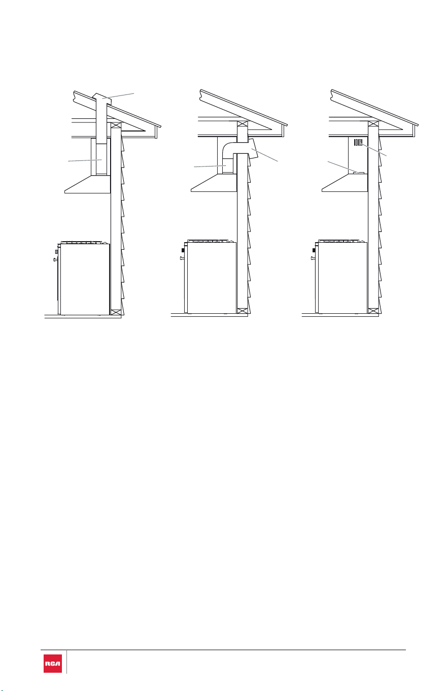
Roof Venting Wall Venting Ductless (Non-Vented)
A.Roof cap
B.6" (15.2 cm) round
duct
A.Wall cap
B.6" (15.2 cm) round
duct
A.Duct opening
B.Chimney venting
holes
Calculating Duct System Length
The recommended duct system is 6" (15.2 cm) round duct with a maximum
length of 35 ft (10.7 m). For the best performance, use no more than three 90°
elbows.
To calculate the length of the system you need, add the equivalent feet
(meters) for each duct piece used in the system.
A
B
A
B
A
B
16
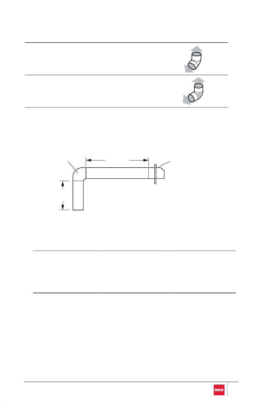
Maximum equivalent duct length is 35 ft (10.7 m).
Example Duct System - 6" (15.2 cm)
Duct Piece
45° elbow
6" (15.2 cm) Round
2.5 ft (0.8 m)
90° elbow 5.0 ft (1.5 m)
90° elbowWall cap
6 ft (1.8 m)
3 ft
(0.93 m)
Maximum length = 35 ft (10.7 m)
1 - 90° elbow
1 – wall cap
6 ft (1.8 m) straight
3 ft (0.9 m) straight
System length
= 14.0 ft (4.3 m)
= 5.0 ft (1.5 m)
= 0.0 ft (0.0 m)
= 6.0 ft (1.8 m)
= 3.0 ft (0.9 m)
17

ELECTRICAL REQUIREMENTS
Observe all governing codes and ordinances.
Ensure that the electrical installation is adequate and in conformance with
National Electrical Code, ANSI/NFPA 70 (latest edition), or CSA Standards
C22.1-94, Canadian Electrical Code, Part 1 and C22.2 No. 0-M91 (latest
edition) and all local codes and ordinances.
If codes permit and a separate ground wire is used, it is recommended that a
qualified electrician determine that the ground path is adequate.
A copy of the above code standards can be obtained from:
National Fire Protection Association
1 Batterymarch Park
Quincy, MA 02169-7471
CSA International
8501 East Pleasant Valley Road
Cleveland, OH 44131-5575
•A 120-volt, 60 Hz., AC-only, 2-amp, fused electrical circuit is required.
•If the house has aluminum wiring, follow the procedure below:
-Connect a section of solid copper wire to the pigtail leads.
-Connect the aluminum wiring to the added section of copper wire
using special connectors and/or tools designed and UL Listed for
joining copper to aluminum.
-Follow the electrical connector manufacturer's recommended
procedure. Aluminum/copper connection must conform with local
codes and industry accepted wiring practices.
•Wire sizes and connections must conform with the rating of the appliance
as specified on the model/serial/rating plate. The model/serial/rating plate
is located behind the left baffle filter on the rear wall of the range hood.
•Wire sizes must conform to the requirements of the National Electrical
Code, ANSI/NFPA 70 (latest edition), or CSA Standards C22. 1-94,
Canadian Electrical Code, Part 1 and C22.2 No. 0-M91 (latest edition) and
all local codes and ordinances.
18
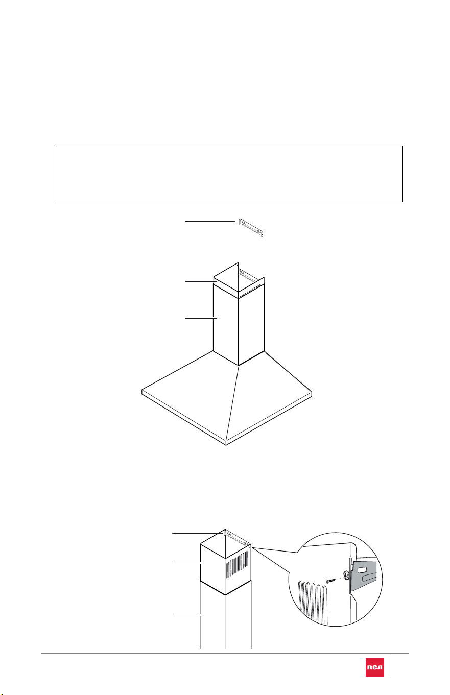
INSTALLATION INSTRUCTIONS
R-RHWM1H30BSS
Inner chimney (upper vent cover)
Outer chimney (lower vent cover)
6" round aluminum duct
19
Range hood (main core)
Metal baffle filters
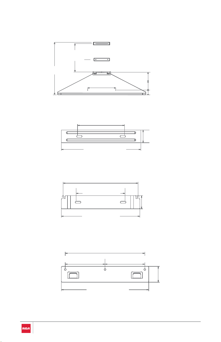
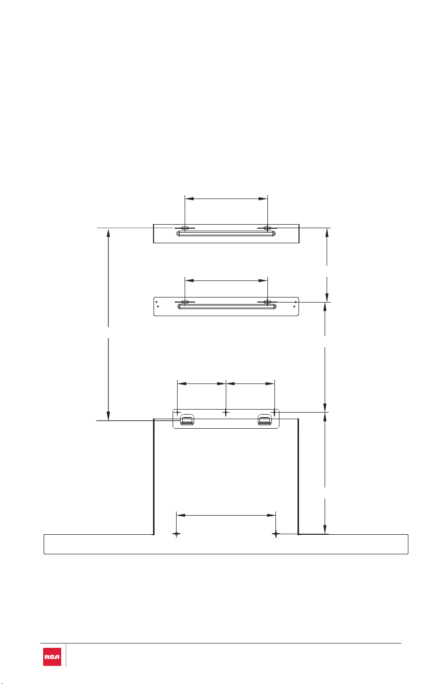
Installation Dimensions for the R-RHWM1H30BSS
13³/8” - 29¹/8” (340mm - 740mm)
41 5/8” (1049mm)
8 7/8” (226mm)
13
13/16”
(350mm)
8 7/8” (226mm)
2 5/16” (58mm)
5¹/8” (130mm)
1³/8” (35mm)
8¹¹/16” (220mm)
Upper Chimney Bracket
7 7/8” (200mm)
5¹/8” (130mm)
8 5/8” (219mm)
Lower Chimney Bracket
7
7/8”
(200mm)
3 5/16” (100mm) 3 5/16” (100mm)
1 9/16” (40mm)
8¹¹/16” (220mm)
Mounting Bracket Hook
20
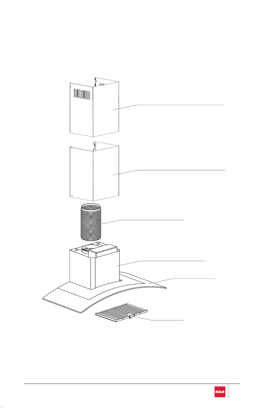
R-RHWM2R30BSS
21
Metal baffle filter
Inner chimney (upper vent cover)
Outer chimney (lower vent cover)
6" round aluminum duct
Range hood (main core)
Tempered glass
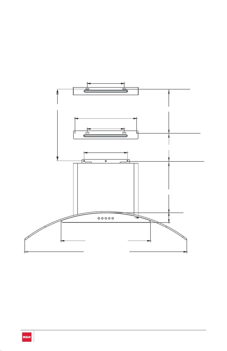
Installation Dimensions for the R-RHWM2R30BSS
3¹¹/16” (170mm)
14 15/16” (380mm)
11¹/4” (285mm)
6¹¹/16” (170mm)
7 7/8” (200mm)
5 1/8”” (130mm
1 ³/4” (45mm)
8 9/16” (218mm)
1 ³/4” (45mm)
16 ¹/4” (413mm)
29 7/16” (748mm)
22
3 15/16” - 13 3/4” (100mm - 350mm)
R-RHWM3S30BSS
23
Inner chimney (upper vent cover)
Outer chimney (lower vent cover)
6" round aluminum duct
Range hood (main core)
Metal baffle filters
Installation Dimensions for the R-RHWM3S30BSS
611⁄16” (170mm)
611⁄16” (170mm) 187⁄8” (480mm)
73⁄4” - 173⁄4” (197mm - 450mm)
815⁄16” (227mm)
315⁄16” (100mm) 315⁄16” (100mm)
913⁄16” (250mm)
81⁄16” (205mm)
24
Prepare Location
•It is recommended that the duct system be installed before the range
hood is installed.
•Before making cutouts, make sure there is proper clearance within the
ceiling or wall for duct fittings.
•Remove installations parts carefully. Wear hand gloves to protect against
sharp edges.
•Remove the foams, tapes, and protective films covering the product
before putting it into operation.
•Confirm that all installations parts have been removed from the shipping
carton and the range hood canopy.
WARNING
EXCESSIVE WEIGHT HAZARD
Use two or more people to move and install range hood.
Failure to do so can result in back or other injury.
CAUTION
LACERATION, FOREIGN OBJECT, CRUSH HAZARD
When installing, moving, or servicing any appliance, wear proper
protective equipment, including cut resistant gloves, steel-toed shoes,
and safety glasses.
1. Disconnect power.
2. Determine which venting method to use: roof, wall, or ductless.
3. Select a flat surface for assembling the range hood. Place covering over
that surface.
4. Using 2 or more people, lift range hood onto covered surface.
25
Brackets Installation
Range Hood Mounting Bracket
WARNING
EXCESSIVE WEIGHT HAZARD
Use two or more people to move and install range hood.
Failure to do so can result in back or other injury.
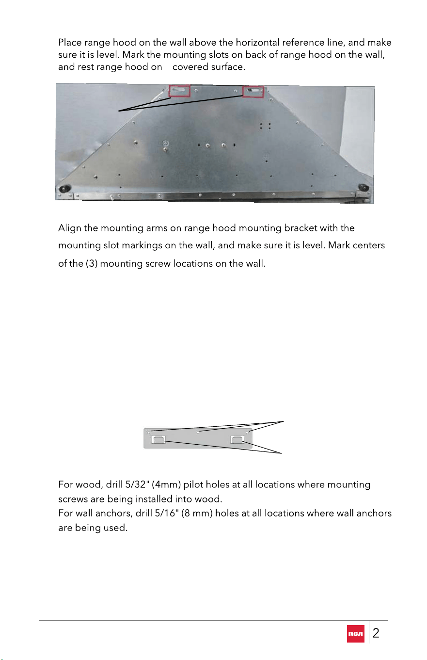
1. Determine and mark the vertical centerline on the wall where the range
hood will be installed.
2. Select a mounting height between a minimum of 25 9/16" (65.0 cm) and a
suggested maximum of 36" (91.4 cm) above the cooktop/range to the
bottom of the range hood. Mark a horizontal line on the wall referencing
the bottom of the range hood.
WALLBACK VIEW
26
NOTE:
wall venting, it is
not necessary for the chimney to be in contact with the ceiling.
• Make sure the chimney can reach the ceiling. For
• For higher ceilings, chimney extensions are available to replace the
chimneys shipped with the range hood. To purchase, visit :
fgsbrands.com/rca-parts or reference the contact information at the
end of this manual.
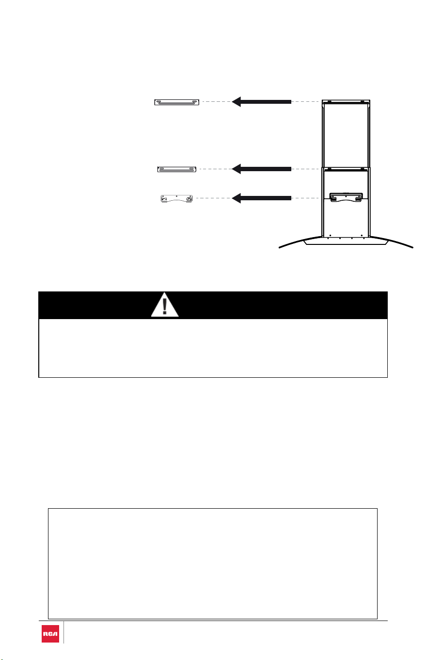
Outer (lower) Chimney Bracket
Inner (Upper) Chimney Bracket
Range Hood Mounting Bracket
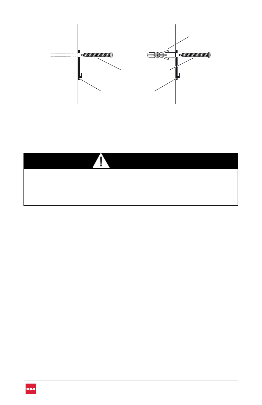
IMPORTANT:
ll Mounting screws must be installed into the wood stud where possible. If
there is no wood stud to screw into, additional wall framing supports may be
required, or use 37.5 mm wall anchors with the 40 mm mounting screws.
3 Mounting Sc
rew Holes
2 Mounting Arms
Range Hood Mounting Bracket
5.
6. Secure the mounting bracket on the wall with (3) mounting screws. For wood,
install the 40 mm mounting screws.
For wall anchors, install the 37.5 mm wall anchors and install the 40 mm
mounting screws into the wall anchors.
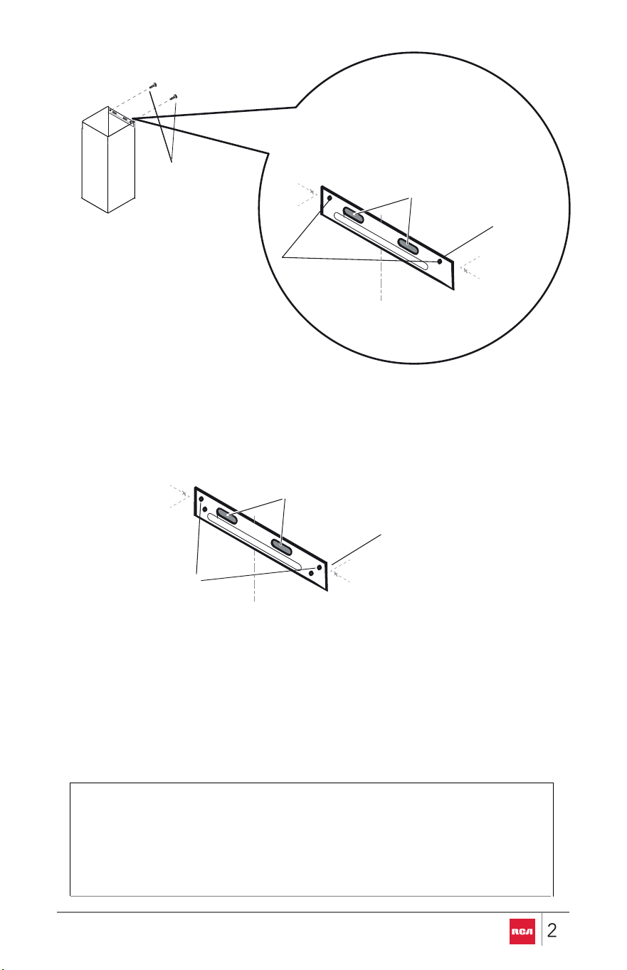
3.
a
Mounting Slots
Mounting Slots behind the Range Hood
4.
5. The back of the range hood features optional multiple mounting holes, you
can mark any 2 of the holes on either side to install 40 mm screws for the
additional support if desired (Optional only applicable for the R-RHWM1H30BSS)
7
Installation steps for the Chimney (Vent Cover) Support
Brackets
WARNING
EXCESSIVE WEIGHT HAZARD
Use two or more people to move and install range hood.
Failure to do so can result in back or other injury.
IMPORTANT:
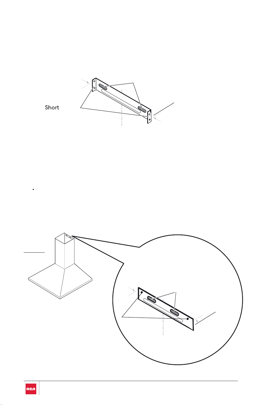
1.Attach the outer (lower) chimney bracket to the outer chimney first, so its two
holes line up with the slots in the chimney.
From the outside, drive the two short screws through the chimney into the bracket
to secure it.
(See figure “Outer (lower) chimney and Bracket for R-RHWM1H30BSS” below)
For R-RHWM2R30BSS and R-RHWM3S30BSS models each side of the outer
(lower) chimney bracket has two short screw holes (four total). When you fasten it,
use the hole closest to the outer edge on each side.
(See figure “Outer (lower) chimney bracket for R-RHWM2R30BSS,
R-RHWM3S30BSS” below)
WALLWOOD STUD
Mounting bracket
Wall anchor
Mounting screw
28
2. Using 2 or more people, hang range hood on mounting bracket through
the mounting slots on back of range hood, so that chimneys mounting
brackets position can be marked.
NOTE:
•To help prevent scratches, lay paper or a kitchen towel over the top
edges of the outer (lower) chimney to protect the surface.
•Make sure the mounting bracket holes are facing up for the ease of
installing.
9
Short
Mounting screw
location
Screws
Marked chimney
short screw
location
Short
Screw holes
Centerline
Outer (lower) chimney and Bracket for R-RHWM1H30BSS
Mounting screw
location
Marked chimney
short screw location
Outer edge Short
Screw holes
Centerline
Outer (lower) chimney bracket for R-RHWM2R30BSS, R-RHWM3S30BSS
30
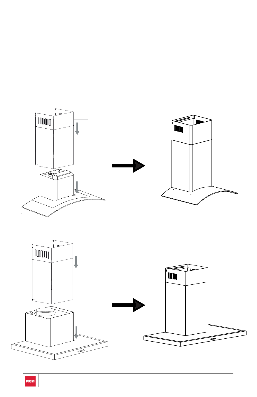
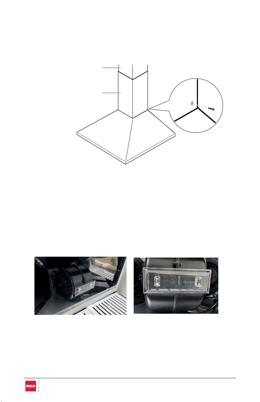
3. Place both inner (upper) and outer (lower) chimneys onto hood. The inner
chimney must slide into the outer chimney.
For R-RHWM2R30BSS & R-RHWM3S30BSS:
Slide the chimneys all the way down until it rests flush on top of the hood.
For R-RHWM1H30BSS:
Slide the chimneys down only until it stops at the peak of the hood’s pyramid
section.
R-RHWM3S30BSS Chimney Positioning
R-RHWM2R30BSS Chimney Positioning
Inner (upper) chimney
Outer (lower) chimney
Inner (upper) chimney
Outer (lower) chimney
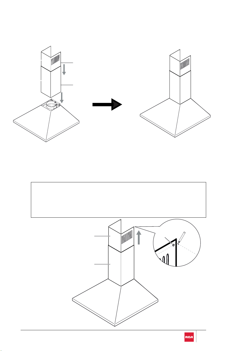
Lift inner (upper) chimney to ceiling. Using a pencil, mark on the wall
adjacent to the inner (upper) chimney the center of the screw locations
near the top on both sides of the inner (upper) chimney. Carefully slide
the inner (upper) chimney down.
NOTE:
•For ductless (recirculating) installations, the venting holes near the
top of the inner (upper) chimney should be exposed from the outer
(lower) chimney to allow air recirculation.
Outer (lower) chimney
Inner (upper) chimney
WALL
Screw
location
Place both inner (upper) and outer (lower) chimneys onto hood. The inner
chimney must slide into the outer chimney.
31
R-RHWM1H30BSS Chimney Positioning
Inner (upper) chimney
Outer (lower) chimney
Align the center of the inner chimney support bracket after raising the
chimney to the celiling with the centerline on the wall, align the screw
hole on both sides of the support bracket with the previously marked
inner (upper) chimney screw locations on the wall. Make sure the support
bracket is level, and mark the (2) mounting screw locations. Lower the
chimney after.
Mounting screw
location
Marked chimne y
screw location
Screw
holes
Centerline
4.
Inner chimney (Upper vent) Mounting Bracket
5 Position the outer (lower) chimney support bracket on the wall with the top of
the outer (lower) chimney hooking onto the support bracket on both sides. Align
the center of the support bracket with the centerline on the wall, and make sure it
is level. Mark the (2) mounting screw locations of the support bracket.
Mounting screw
location
Marked chimney
screw location
Short
Screw holes
Centerline
Outer chimney (Lower vent) Mounting Bracket
32
Outer (lower) chimney
WOOD STUD WALL
Wall anchor
Mounting screw
Mounting bracket
33
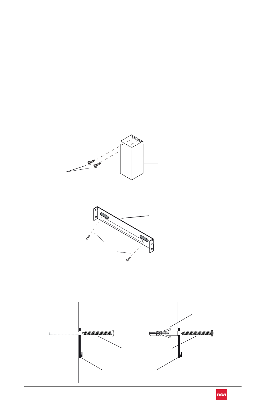
6.Detach the range hood and chimneys from the wall and place them on a
covered surface.
For wood, drill 5/32" (4mm) pilot holes at all locations where mounting
screws are being installed into wood.
For wall anchors, drill 5/16" (8 mm) holes at all locations where wall
anchors are being used. Then insert anchors into the wall.
7.Verify if you have followed the steps below before proceeding to the
next step:
Position the lower-chimney support bracket (already attached to the
chimney) against the wall, make sure it’s centered and level, then fasten
it with two mounting screws.
Outer (lower) chimney with
mounting bracket
Mounting
Screws
Inner (upper) mounting
bracket
Mounting Screws
For wood, install the 40 mm mounting screws.
For wall anchors, install the 37.5 mm wall anchors and install the 40 mm
mounting screws into the wall anchors.
Now attach Inner (upper) chimney support bracket to the wall with (2)
mounting screws.
Install Range Hood
WARNING
EXCESSIVE WEIGHT HAZARD
Use two or more people to move and install range hood.
Failure to do so can result in back or other injury.
WARNING
ELECTRIC SHOCK HAZARD
Disconnect power before servicing.
Replace all parts and panels before operating.
Plug into a grounded 3-prong outlet.
Failure to do so can result in death, fire, or electrical shock
1. Using 2 or more people, hang the range hood back on the mounting
bracket through the mounting slots on back of the range hood.
2. Check and verify the round damper is properly installed into the duct
opening of the range hood.
3. For ducted installations only: Connect one end of 6" round aluminum
duct to the top duct opening of the range hood, and the other end to the
34
existing duct system. Seal connections with clamps or HVAC foil tape (not
included).
4. Plug range hood into a grounded 3-prong outlet.
5. Place both inner (upper) and outer (lower) chimneys onto hood, and hang
outer chimney onto the lower support bracket on the wall. The inner
chimney must slide into the outer chimney.
NOTE:
•To help prevent scratches, lay paper or a kitchen towel over the top
edges of the outer (lower) chimney to protect the surface.
6.Lift inner (upper) chimney to upper support bracket on the wall, install
with
(2) 4 x 8 mm screws on both sides of the chimney, or hang chimney onto
the support bracket.
Inner (upper) chimney
Outer (lower) chimney
Inner (upper) chimney
support bracket
Inner (upper) chimney
support bracket
Inner (upper) chimney
Outer (lower) chimney
35
7. For models with screw holes on the range hood aligning with
the screw holes on both sides of the outer (lower) chimney at the bottom,
install (2) 4 x 8 mm flat screws, if you haven't already.
Complete Installation
Outer (lower) chimney
Inner (upper) chimney
1. For ductless (recirculating) installations only: Install charcoal filters ove r
grille on blower housing. See the "Range Hood Care" section.
2. For models with oil tray included: Make sure the oil tray is on the
blower.
3. Install metal baffle filters. See the "Range Hood Care" section.
4. Check the operation of the range hood blower and light. See the "Rang e
Hood Use" section.
36
RANGE HOOD USE
The range hood is designed to remove smoke, cooking vapors and odors from
the cooktop area. For best results, start the range hood before cooking and
allow it to operate several minutes after the cooking is complete to clear all
smoke and odors from the kitchen.
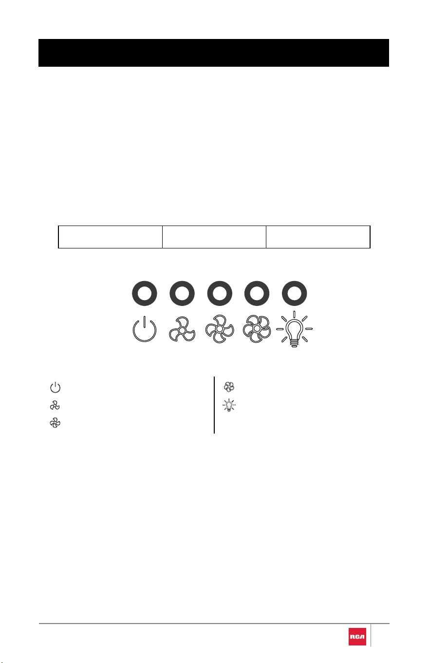
Controls
Push-Button Models
R-RHWM1H30BSSR-RHWM2R30BSSR-RHWM3S30BSS
Blower Off button
Blower speed minimum button
Blower speed medium button
Blower speed maximum button
Light On/Off button
37
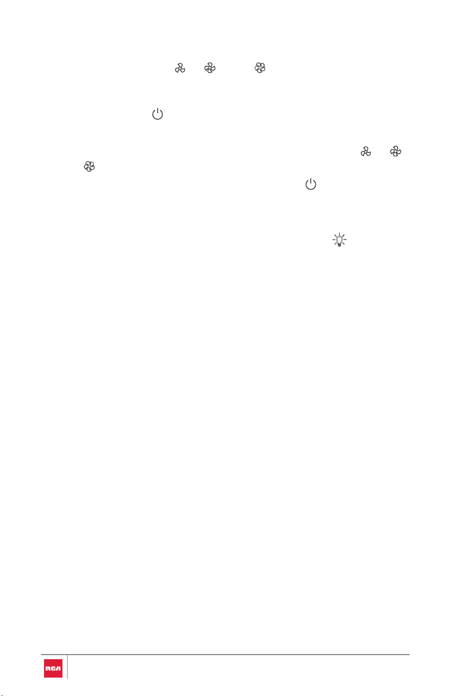
Operating the Blower
The Blower Speed buttons ( , , and ) set the desired speed and
control the sound level for quiet operation. The speed can be changed
anytime during fan operation by pressing the desired blower speed button.
The Blower Off button turns the blower off.
peed button ( , ,
.
Operating the Light
1. To turn the lights on or off, press the Light On/Off button once.
1. To turn the blower on, press the desired Blower S
or ).
2. To turn the blower off, press the Blower Off button
38

RANGE HOOD CARE
Cleaning
IMPORTANT:
•Clean the range hood and grease filter frequently according to the
following instructions. Replace grease filter before operating range hood.
•Be sure the power is off/disconnected and the lights are cool before
cleaning the range hood.
Exterior Surfaces
Clean the range hood with a mild detergent and soft cloth. To avoid damage
to the exterior surface, do not use abrasive cleansers or steel-wool pads
Metal Grease Baffle Filter
The metal baffle filter should be washed frequently. Place stainless steel
baffle filter in dishwasher or hot detergent solution to clean. Black painted
filter should only be cleaned in hot detergent solution. Let metal baffle filter
dry thoroughly before replacing it.
1. Turn off fan and lights. Check that the LED lights are cool.
2. Remove the metal baffle filter by pushing the release knob and then
pulling down the metal baffle filter.
3. Wash the metal baffle filter as needed in the dishwasher or hot detergent
solution.
4. Reinstall the metal baffle filter by pushing the release knob, pushing up
the metal baffle filter back into the range hood, and releasing the knob to
latch into place.
39
Replacing the Charcoal Filter
For Ductless (Recirculating) Installations
After approximately 6 months of normal use the charcoal filter should be
replaced. To order replacement charcoal filter kit, see "Optional Parts" in the
"Tools and Parts" section.
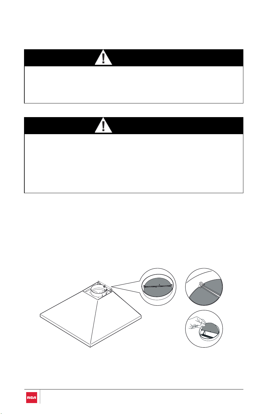
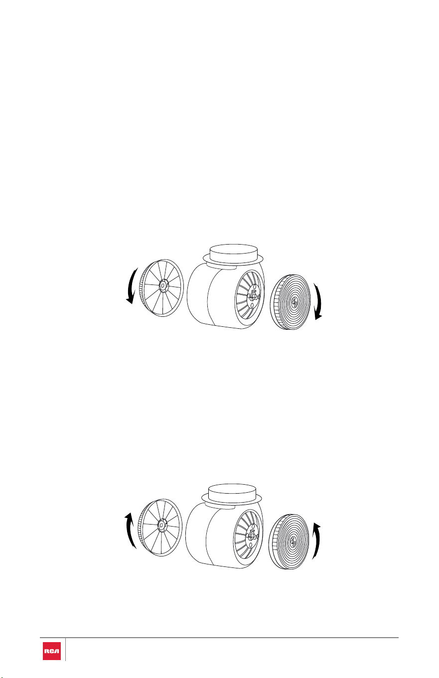
To Install Charcoal Filter
1.Turn off fan and lights. Check that the LED lights are cool.
2.Remove the metal baffle filters. See the "Metal Grease Baffle Filter" section.
3.Fit and turn clockwise the charcoal filter on both sides of the fan motor. Be
sure the charcoal filters are securely locked in place.
4. Reinstall the metal baffle filters into the range hood.
To Replace Charcoal Filter
1.Turn fan and lights off. Check that the LED lights are cool.
2.Remove the metal baffle filters. See the "Metal Grease Filter" section.
3.Turn counter-clockwise and remove the charcoal filters, and discard
them.
4.Install the replacement charcoal filters. See the "To Install Charcoal Filter"
section.
5.Reinstall the metal baffle filters into the range hood.
40
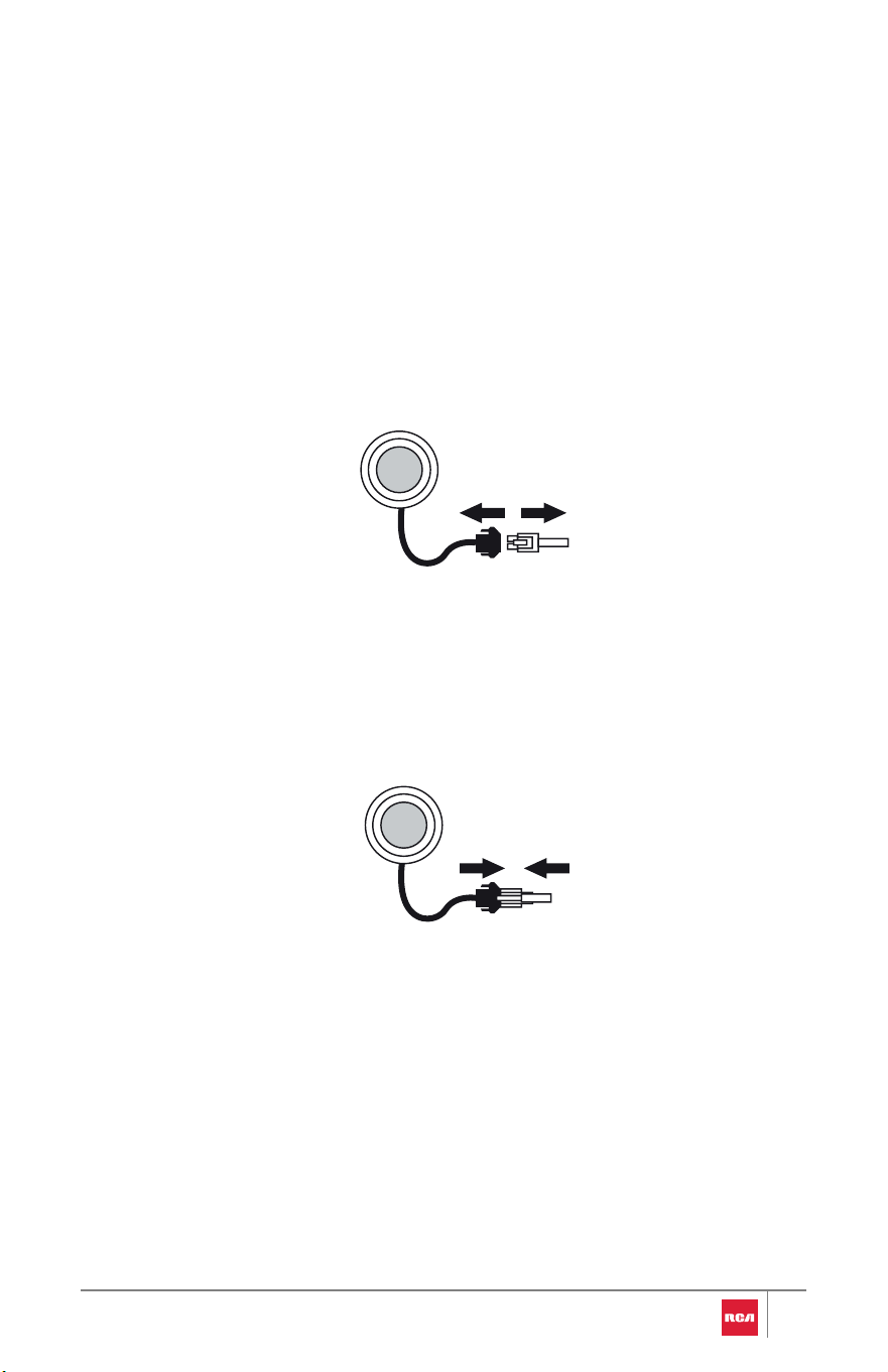
Replacing the LED Light
Turn off the range hood and allow the LED Lights to cool. Replace the LED
lights using tissue or wearing cotton gloves to handle them.
1. Disconnect power.
2. Remove the metal baffle filters. See "Metal Grease Baffle Filter" in the
"RANGE HOOD CARE" section.
3. Disconnect the LED light cable from the range hood.
4. Use a flat-blade screwdriver to gently pry and remove the LED light.
5. Install a replacement LED light. Be sure to properly align the LED light with
the opening and the LED light is securely locked into place.
6. Connect the LED light cable to the range hood.
7. Reinstall the metal baffle filters into the range hood.
8. Reconnect power.
41
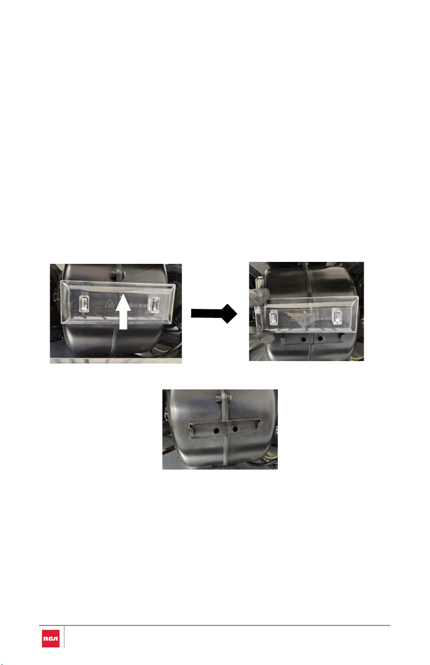
Cleaning the Oil Tray
1. Disconnect power.
2. Remove the metal baffle filters. See "Metal Grease Baffle Filter" in the
"RANGE HOOD CARE" section.
3. Push the oil tray up to remove it.
It is recommend giving the oil tray a quick wipe-down each week, a basic wash
with warm, soapy water once a month, and a thorough deep clean every 2–3
months.
42
4. Tilt the tray over a small container or disposable cup and pour out the
collected oil.
Soak briefly in warm, soapy water, then scrub gently with a soft sponge
to remove residue.
5.
6. Wipe the tray completely dry, then slide it back down into its slot.
7. Reinstall the metal baffle filters into the range hood.

LIMITED WARRANTY
WARRANTY AND SERVICE
TO RECEIVE WARRANTY SERVICE, YOUR PRODUCT MUST BE REGISTERED.
TO REGISTER AND REVIEW FULL WARRANTY DETAILS, VISIT:
FGSBRANDS.COM/RCA-WARRANTY
SCAN TO REGISTER
CUSTOMER SUPPORT
TO CONTACT CUSTOMER SERVICE FOR ASSISTANCE, VISIT:
FGSBRANDS.COM/RCA-HELP
SCAN TO CHAT
43

IMPORTANT
Do Not Return This Product To The Store
If you have a problem with this product, please contact Customer Support at
+1 (626) 800-4288
DATED PROOF OF PURCHASE, MODEL #, AND SERIAL # REQUIRED FOR
WARRANTY SERVICE.
IMPORTANT
Ne pas Réexpédier ce Produit au Magasin
Pour tout problème concernant ce produit, veuillez contacter le service des
consommateurs Customer Support au
+1 (626) 800-4288
UNE PREUVE D’ACHAT DATEE EST REQUISE POUR BENEFICIER DE LA
GARANTIE.
IMPORTANTE
No regrese este producto a la tienda
Si tiene algún problema con este producto, por favor contacte el ayuda al
cliente al
+1 (626) 800-4288
(Válido solo en E.U.A.)
NECESITA UNA PRUEBA DE DE COMPRA FECHADA, NÚMERO DE MODELO Y
DE SERIE PARA EL SERVICIO DE LA GARANTÍA.
Correct Disposal of this product:
This marking indicates that this appliance should
not be disposed with other household wastes.
To prevent possible harm to the environment or
human health from uncontrolled waste disposal,
recycle it responsibly to promote the sustainable
reuse of material resources.
44
45
Memo
46
Memo

47
Memo

For service assistance and product
information please call:
1-626-800-4288
Electronic version of this manual is
available at:
www.fgsbrands.com/rca-manuals
This product has been manufactured and sold under the responsibility of
Future Global Supply, LLC.
RCA, the RCA logo and the two dogs (Nipper and Chipper) logo are
trademarks used under license by Future Global Supply, LLC – further
information at www.rca-brand.com.
All other products, services, companies, trademarks, trade or product names
and logos referenced herein are the property of their respective owners.
®
®
