Works with LED,
Incandescent and halogen bulbs
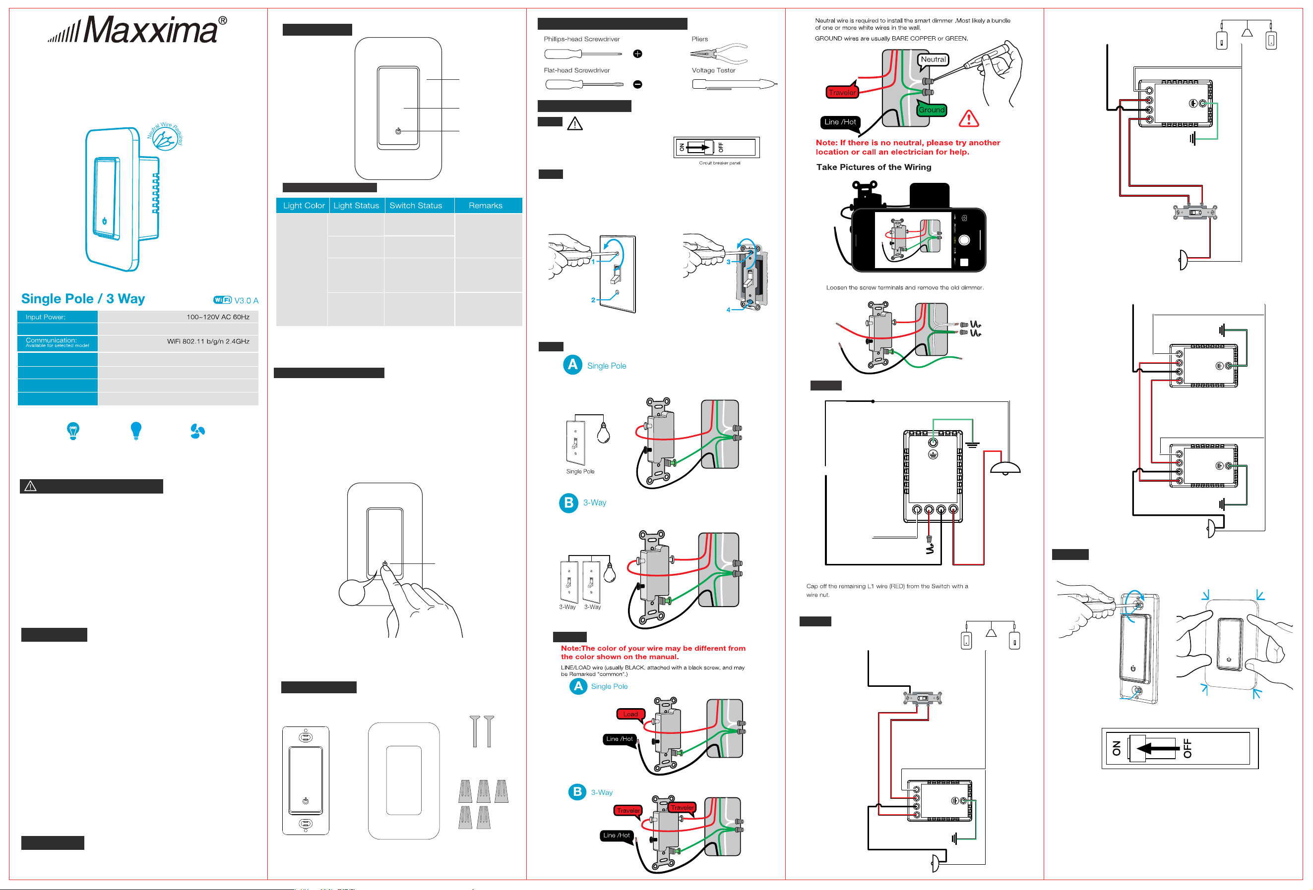
Installation Instructions
for Smart LED Switch
MEW-S1013DW
● Risk of fire and electrical shock, products should be installed in
accordance with appropriate electrical codes and regulations.
● Turn power off at circuit breaker or fuse and test that power is off
before installing.
● If you are unsure about any part of these instructions, consult a
licensed electrician.
● To reduce the risk of overheating and possible damage to other
equipment, do not install to control a receptacle, a motor-operated
appliance or a transformer-supplied appliance.
● Use with compatible dimmable LED, Incandescent or
halogen bulbs only.
● When multiple bulbs are used with one dimmer, DO NOT mix bulb
types. All bulbs shall be either LED, halogen or incandescent. Using
the same model of each bulb will enhance dimmer performance.
WARNINGS AND CAUTIONS
Product Outline
Tools needed to install your Dimmer
Installation and testing
Step 2
Removing existing switch: Remove existing wall plate and
switch mounting screws. Carefully pull switch from wall box,
identify and take out the wires attached to the switch, then
remove the switch. DO NOT remove the wires which are taken
out from the switch at this time.
Step 1
WARNING: To avoid fire and electrical shock,TURN
OFF POWER at circuit breaker or fuse and test that
power is off before wiring.
Step 3
Status Indicator
FCC Information
This device complies with Part 15 of the FCC Rules. Operation is subject
to the following two conditions:
(1) This device may not cause harmful interference, and (2) This device
must accept any interference received, including interference that may
cause undesired operation.
This equipment has been tested and found to comply with the limits for a
Class B digital device, pursuant to part 15 of the FCC Rules. These limits
are designed to provide reasonable protection against harmful interference
in a residential installation. This equipment generates, uses and can
radiate radio frequency energy and, if not installed and used in
accordance with the instructions, may cause harmful interference to radio
communications. However, there is no guarantee that interference will not
occur in a particular installation. If this equipment does cause harmful
interference to radio or television reception, which can be determined by
turning the equipment off and on, the user is encouraged to try to correct
the interference by one or more of the following measures:
- Reorient or relocate the receiving antenna.
- Increase the separation between the equipment and receiver.
- Connect the equipment into an outlet on a circuit different from that to
which the receiver is connected.
- Consult the dealer or an experienced radio/TV technician for help.
FCC CAUTION
Any changes or modifications to this unit not expressly approved by the
manufacture could void the user's authority to operate the equipment.
Using the On/Off Switch
●
To turn on the light: Press the On/Off switch once when the
lights are off
● To turn off the light: Press the On/Off switch once when the
lights are on
● Factory Reset: Hold the switch for 8s until the indicator light is
flashing to reset the switch and go into quick configure mode.
Identify the old Switch’s Wiring application
Step 5a Wire the Smart Switch - Single Pole
Step 6
Mount the Switch and click in the wallplate and turn
on power
Only one switch controls one light or bundle of lights
Two switches control the same light or the same bundle of lights.
Breaker Box
Control:
Relay
Max Current:
Standby Power:
Button Life:
10A
≤1W
500K times
105*45*42.5 mmDimension:
Recommended loads:
LED Motor
—up to 600W —up to 0.6 HP
Incandescent/halogen
—up to 1000W
ON/OFF
LED Indicator
Cover Panel
Green
OFF
ON
Power OFF
Support Self-
denition on APP
Power ON(Default)
Blink Quickly
(0.5s )
Blink Slowly
(1s )
Ready for AP
(Access Point)
conguration mode
Ready for default
conguration mode
8s
LED Flashing
Neutral
Common
L1
L2
Neutral(White)
NL
Line /Hot(black)
Ground
(Green)
3-way Smart Switch
Common
Line /Hot(black)
Ground
(Green)
Neutral
Common
L1
L2
NL
Traveler
Traveler
Neutral(White)
3-way Smart Switch
Traditional
Switch
Smart
Switch
Replace BOTH of your REGULAR 3-WAY
SWITCHES with SMART SWITCHES
3-way Smart Switch
3-way Smart Switch
Neutral
Common
L1
NL
Neutral
Common
L1
L2
Neutral(White)
Ground
(Green)
Line /Hot(black)
Ground
(Green)
Traveler
Traveler
L2
Parts Supplied
Switch Panel
Screws
Wire Caps
Step 4 Identify Line, Load, and Neutral Wires
Step 5b
Wire the Smart Switch - 3-Way
Common
L2
L1
Neutral(White)
Line /Hot(black)
Traveler
Traveler
NL
Ground
(Green)
Neutral
Common
L1
L2
3-way Smart Switch
Traditional
Switch
Smart
Switch
Replace ONE of your REGULAR 3-WAY
SWITCHES with SMART SWITCH
1
2
The light(s) may ash once during smart switch
rst time power up
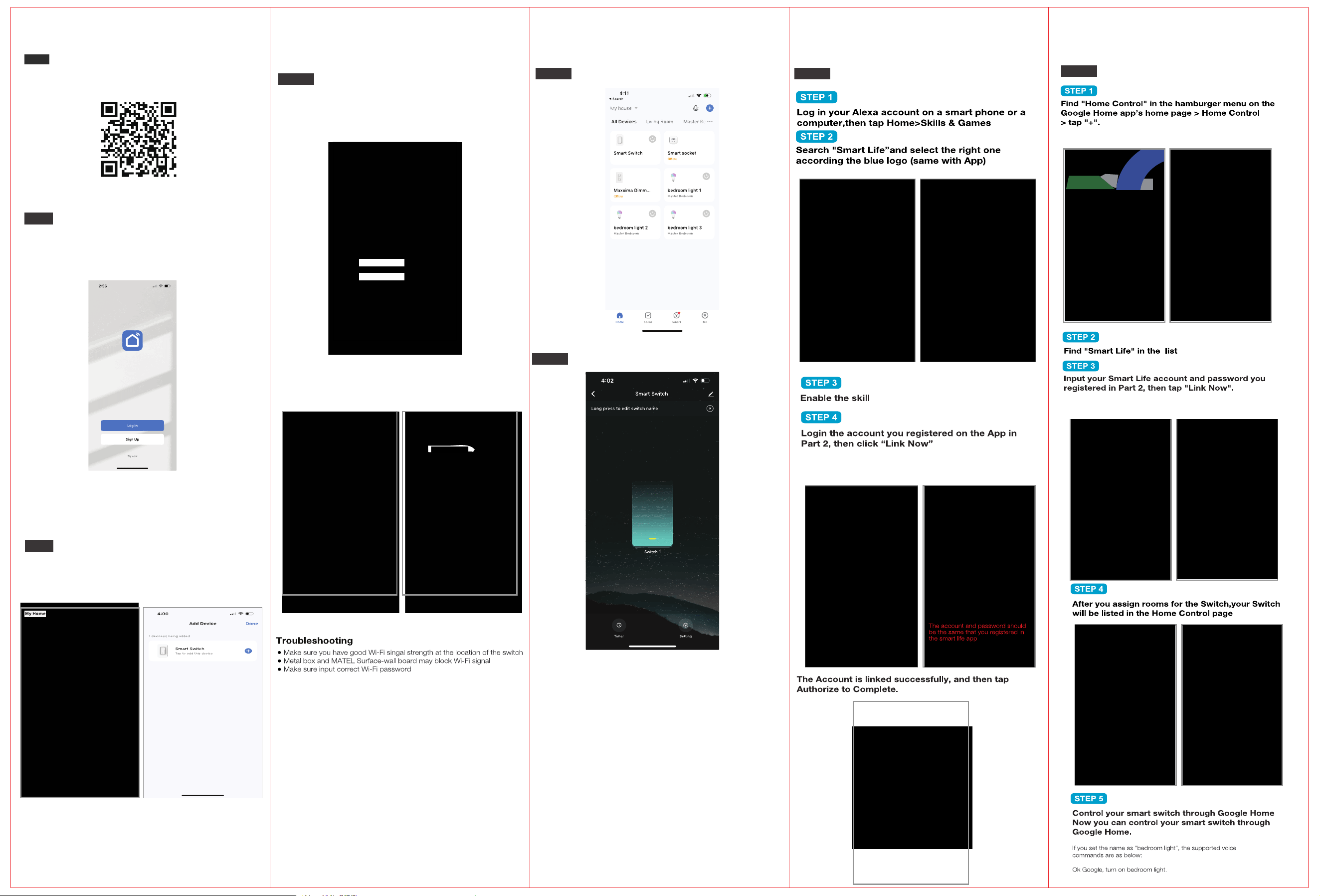
● Scan the QR code below to download the ‘Smart Life’ App.
● You can also download this app in the app store/Android
app store by searching "Smart Life" or “Tuya”
Step 1
Download the ‘Smart Life’ or Tuya App
Register an account and Login
Step 2
●Enter the Register/Login interface; tap “Register” to create an
account by entering your phone number to get a verification
code and setting your password. Choose “Log In” if you
already have a Smart Life Account
Connect with the switch
Step 3
● Click ‘Add Device’ or the ‘ + ’ in the top right-hand corner.
● Click ‘Electrical’ then Switch (Wi-Fi) to enter the
device connection interface.
Quick Configuration Mode
Step 3a
●Press and hold the Switch button for 8s to reset the switch &
go into quick config. mode
●Select your home Wi-Fi and enter the password. Then click
confirm to go to the next screen.
●Wait for the system to search for the device, connect, and
configure the switch. It may take up to 3 min. to connect
●Once the device configures successfully, please input your
preferred name and select a location for the switch.
The switch can be viewed in the Main Menu
Step 4
Control the Switch through the App
Step 5
●The app allows you to turn on and off the switch
Smart Life Skills (Alexa)
Step 6
Smart Life Skills (Google)
Step 7