REV A DATE: 10/03/2023
USER MANUALS\21-31395_FUSION_USER MANUAL_FBR6S-5R-8110_REF_SUB PREP_FLAT TOP WORK AREA_CASE
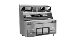
FUSION REFRIGERATED MODEL FBR6S-5R.8110 SUB PREP WITH FLAT TOP WORK AREA
> SELF-CONTAINED R290 SYSTEM WITH FLAMMABLE REFRIGERANT
> MULTIPLE SANALITE WORK SURFACES/CUTTING BOARDS
> REFRIGERATED DRAWERS and CUBBY FOR STORAGE
> CHANNEL FOR LABEL/TISSUE BOX STORAGE
--- Model FBR6S-5R.8110 Shown Above ---
Structural Concepts Corp. ∙ 888 E. Porter Rd ∙ Muskegon, MI 49441 Phone: 231.798.8888 Fax: 231.798.4960 ∙ www.structuralconcepts.com
USER
MANUAL
FUSION
READ AND SAVE THESE INSTRUCTIONS
SCC P/N
21-31395
2
TABLE OF CONTENTS
OVERVIEW: REFRIGERATION TEMPERATURES, NSF/ANSI TYPE II CONDITIONS,
COMPLIANCE, WARNINGS ....……………………………………………………………………….
OVERVIEW, CONT’D: WARNINGS, CONT’D, REFRIGERANT DISCLOSURE STATEMENT,
DANGER .. ………………………………………………………………………………………………..
OVERVIEW, CONT’D: CAUTION (MINIMUM ROOM FLOOR AREA REQIRED, PLACEMENT LIMITS
(LOBBIES/EGRESS), CONSIDERATION OF CHILDREN, REFRIGERANT RECOVERY,
RECYCLING AND DISPOSAL ………………………………………………………………………….
OVERVIEW, CONT’D: CAUTION (SHELF LOADS LIMITS, LAMPS, GFCI, POWER CORD & PLUG
MAINTENANCE, WIRE DIAGRAM PLACEMENT, ETC.) ..………………………………………….
OVERVIEW, CONT’D: QUALITY OF WORKING PERSONNEL / SERVICING UNITS, WORK
PROCEDURE, GENERAL WORK AREA, CHECKING REFRIGERANT, FIRE EXTINGUISHER
OVERVIEW, CONT’D: IGNITION SOURCES, VENTILATED AREA, CHECKS TO REFRIGERATED
EQUIPMENT, CHECKS TO ELECTRICAL DEVICES ……………………………………………….
OVERVIEW, CONT’D: ELECTRICAL DEVICE CHECK, CONT’D, SEALED COMPONENT REPAIRS,
INTRINSICALLY SAFE COMPONENT REPAIRS, CABLING ……………………………………...
OVERVIEW, CONT’D: DETECTION OF FLAMMABLE REFRIGERANTA, REMOVAL AND
EVACUATION …………………………………………………………………………………………….
OVERVIEW, CONT’D: REMOVAL AND EVACUATION, CONT’D, CHARGING PROCEDURES ……....
INSTALLATION: REMOVAL OF CASTER BRACKETS FROM SKID ……………………………………
INSTALLATION, CONT’D: CASE REMOVAL FROM SKID / POSITIONING / CASTER LOCKING ....
INSTALLATION, CONT’D: CONNECTIONS CHECK / REATTACH PANEL / TURNING ON POWER …..
GENERAL MERCHANDISER ILLUSTRATION - MODEL FBR6S-5R.8110 …...…………………….….
CLEANING SCHEDULE (TO BE PERFORMED BY STORE PERSONNEL) …..……………...…….….
PREVENTIVE MAINTENANCE - TO BE PERFORMED BY TRAINED SERVICE PROVIDERS ....…..
TROUBLESHOOTING (TO BE PERFORMED BY TRAINED SERVICE PROVIDER ONLY) …………
TROUBLESHOOTING - R-290 CONDENSING SYSTEM (BY TRAINED SERVICE PROVIDERS) .....
TROUBLESHOOTING - R-290 EVAPORATOR SYSTEM (BY TRAINED SERVICE PROVIDERS) ....
SERIAL LABEL LOCATION & INFORMATION LISTED / TECH INFO & SERVICE ……….…….……
PROGRAMMABLE CONTROLLER INFORMATION………………………………………..………….…..
TECHNICAL SERVICE CONTACT INFORMATION / WARRANTY INFORMATION …...……………..
3
4
5
6
7
8
9
10
11
12
13
14
15-21
22
23-24
25-27
28
29
30
31
32
3
OVERVIEW
• These cases are designed to merchandise packaged
products at 41 °F (5 °C) or less product temperatures.
• Product must be pre-chilled to 41 °F (5 °C) or less
product temperatures prior to placing in merchandiser.
• Cases should be installed and operated according to
this operating manual’s instructions to ensure proper
performance. Improper use will void warranty.
NSF/ANSI TYPE II ENVIRONMENTAL CONDITIONS
• This unit is designed for the display of products in
ambient indoor store conditions where temperature and
humidity are maintained within a specific range.
• This NSF/ANSI Type II display refrigerator is intended to
be used where environmental conditions are controlled
and maintained so that ambient temperature does not
exceed 80 °F (27 °C) and 55% relative humidity.
• Due to atmospheric pressure considerations, it is not
recommended that these box door cases operate
beyond 6,562 FASL (feet above sea level) / 2,000 MASL
(meters above sea level). If your facility exceeds this
thresholds, please contact Structural Concepts Corp.
COMPLIANCE
• Performance issues when in violation of applicable NEC,
federal, state and local electrical and plumbing codes
are not covered by warranty. See below.
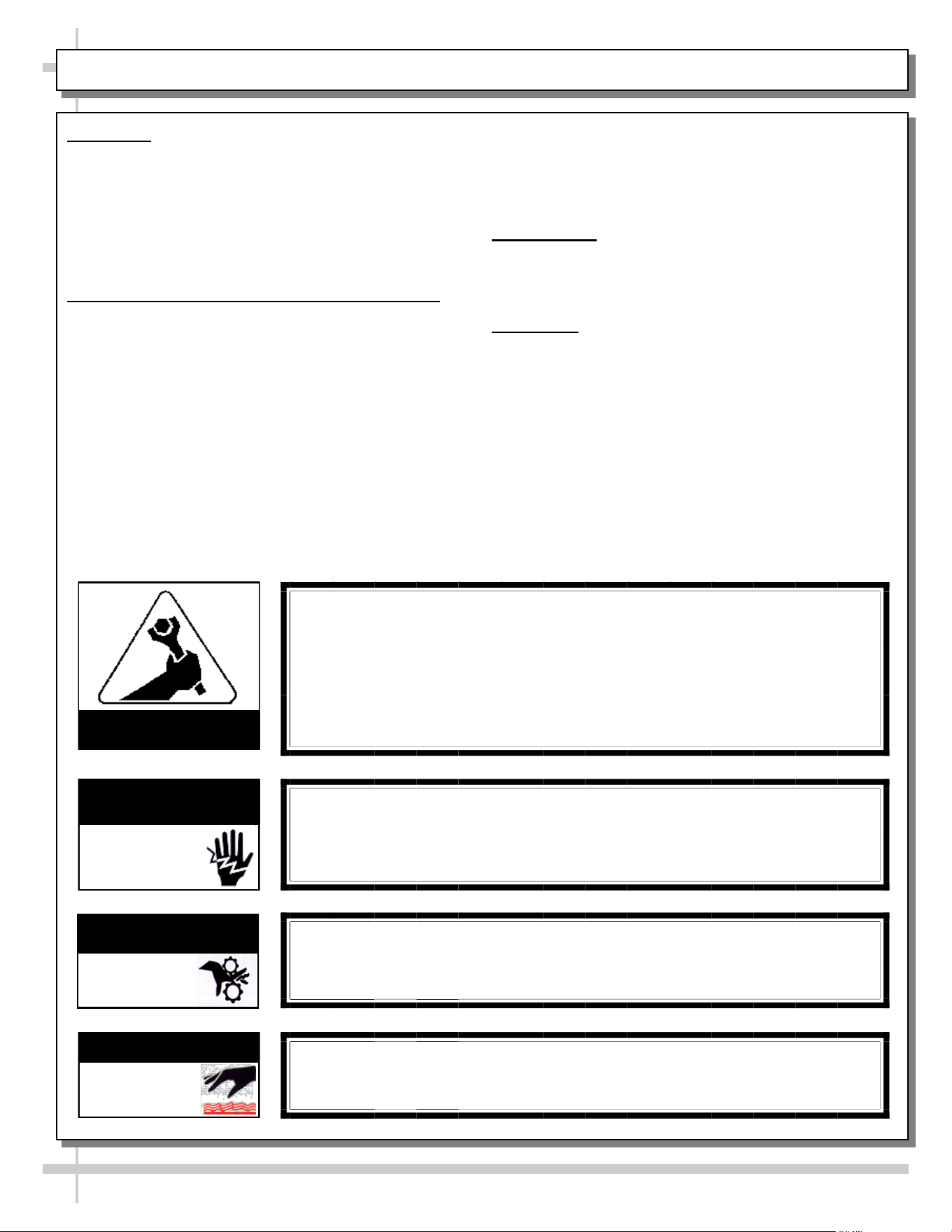
WARNINGS
Carefully read warnings listed below to prevent electrical
shock or injury (including burns) to fingers, hands or other
extremities.
>> See next page for continuation.
WARNING
Hazardous moving parts. Do not operate unit with covers removed.
Fan blades may be exposed when deck panel is removed.
Disconnect power before removing deck panel.
WARNING
Risk of electric shock. Disconnect power before servicing unit.
CAUTION! More than one source of electrical supply is
employed with units that have separate circuits.
Disconnect ALL ELECTRICAL SOURCES before servicing.
WARNING
Condensate Pan is Hot!
Disconnect and allow to cool before cleaning or removing from case.
WARNING
ELECTRICAL
HAZARD
WARNING
HOT
SURFACE
COMPLIANCE
• These cases MUST be installed in compliance with all applicable NEC,
federal, state and local electrical and plumbing codes.
• These cases must ALSO be installed in accordance with the Safety
Standard for Refrigeration Systems, ANSI/ASHRAE 15.
• ONLY factory authorized service personnel are to service these box cases.
• Service shall ONLY be performed on these box cases as recommended by
the manufacturer.
OVERVIEW: REFRIG. TEMPS, NSF/ANSI TYPE II COND., COMPLIANCE, WARNINGS - PAGE 1 of 9
ATTENTION
CONTRACTORS
WARNING
KEEP HANDS
CLEAR
4
OVERVIEW, CONT’D
WARNINGS, CONT’D
• Carefully read warnings listed below to prevent damage
to product, equipment or yourself.
WARNING: REFRIGERANT DISCLOSURE STATEMENT
• This equipment is prohibited from use in California with
any refrigerants on the “List of Prohibited Substances” for
that specific end-use, in accordance with California Code
of Regulations, title 17, section 95374.
• This disclosure statement has been reviewed and
approved by Structural Concepts and Structural
Concepts attests, under penalty of perjury, that these
statements are true and accurate.
DANGER - RISK OF FIRE OR EXPLOSION
• There is a risk of gas under high pressure, risk of fire
explosion, etc.
• Specific storage guidelines, service guidelines, LFL
(lower flammability limit), etc.
• Read specifics below.
>> See next page for continuation.
OVERVIEW, CONT’D: WARNINGS, CONT’D, REFRIG. DISCLOSURE STMT, DANGER - PAGE 2 of 9
WARNING
This product can expose you to chemicals, including
Urethane (Ethyl Carbamate), which are known to the state of
California to cause cancer and birth defects or other reproductive harm.
For more information go to P65Warnings.ca.gov.
WARNING
• Do not use means to accelerate the defrosting process or to clean, other than
those recommended by the manufacturer.
• The case shall be stored in a room without continuously operating ignition
sources (for example, open flames, an operating gas appliance or an operating
electric heater).
• Do not pierce or burn.
• Be aware that refrigerants may NOT contain an odor.
• You must keep required ventilation openings clear of obstruction.
DANGER
• Refrigeration unit contains gas under high pressure. Do not tamper with or
puncture the system. Contact qualified service personnel before disposal.
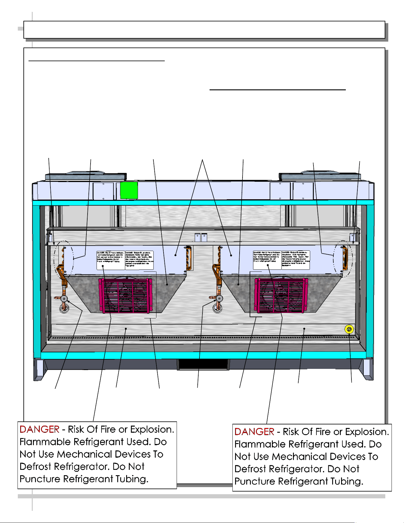
• Risk of fire or explosion. Flammable refrigerant is used in this case.
• Consult repair manual/owner’s guide before servicing this product.
• Do not store explosive substances (such as aerosol cans with a flammable
propellant) in this case.
• Do not use an electrical appliance INSIDE the food storage compartments
unless its type is recommended by manufacturer.
• To minimize risk of ignition due to incorrect parts or improper service, this case
is ONLY to be serviced by factory authorized service personnel.
• Flammable refrigerant type specified on case nameplate is on serial label.
• Model FBR6S-5R.8110 contains a charge of 150g (5.3 ounces) of R290 refrigerant
with a lower flammability limit (LFL) of .038kg/m³ (.035 oz/ft³).
5
OVERVIEW, CONT’D
CAUTION
• This sheet also details the area required for
operation, areas to avoid placing case, guidelines
for children (and others with limited capabilities)
while near box door cases.
• This sheet also provides information on refrigeration
recovery, recycling and disposal.
• This sheet also provides information on recycling and
disposal of refrigerant (including appropriate labeling of
equipment thereto).
• Read specifics below.
>> See next page for continuation.
OVERVIEW, CONT’D: CAUTION (AREA REQ’D, PLCMT LIMITS, CHILDREN, REC,/DISP.) - PAGE 3 of 9
CAUTION
• This unit is not intended for use by persons (including children) with reduced
physical, sensory or mental capabilities, or lack of experience and knowledge,
unless they have been given supervision or instruction concerning use of the
unit by a person responsible for their safety.
• Children should be supervised to ensure that they do not ‘play with’ the unit.
CAUTION
CAUTION: REFRIGERANT RECOVERY/RECYCLING/DISPOSAL
• When recycling or discarding case, refrigerants MUST BE handled according
to local, state and federal codes, requirements and regulations.
• If disposing of a refrigerated case that uses ozone depleting chemicals in its
refrigeration system, make sure the refrigerant is removed by a qualified
service technician and properly disposed of.
• If you intentionally release refrigerant into the atmosphere, you may be
subject to fines or other penalties (under regulations mandated by
environmental regulators and/or legislative edict).
CAUTION: REFRIGERANT RECYCLING/DISPOSAL / UNIT LABELING
• These units contains FLAMMABLE REFRIGERANTS.
• Before recycling or disposing of your unit, FLAMMABLE REFRIGERANTS must
be recovered/recycled/disposed of.
• After FLAMMABLE REFRIGERANT has been removed by a qualified service
technician, ensure that there are labels on the equipment stating the equipment
HAD contained FLAMMABLE REFRIGERANT.
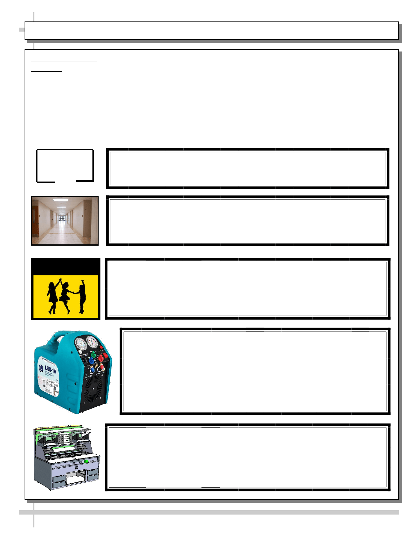
≥7.1m² (23.29ft²)
CAUTION
Minimum room floor area required for operation of
these box door cases is ≥7.1m² (23.29ft²).
CAUTION
• These cases are NOT to be installed in lobbies or locations of egress, such as
hallways, public corridors.
• If case is placed in an enclosure or surrounding structure, keep all of the case’s
ventilation openings clear of obstructions.
6
OVERVIEW, CONT’D
CAUTION, CONT’D
• This sheet contains cautionary notes and information
on shelving load limits, breaker use, thermometers,
thermostats, power cord/plug maintenance, checking
condensate pan, and wiring diagram format & location.
• Wiring diagram location/placement varies depending
CAUTION! POWER CORD AND PLUG MAINTENANCE
Risk of electric shock. If cord(s) and/or plug(s) becomes damaged,
replace only with cord(s) and/or plug(s) of same type.
CAUTION! CHECK CONDENSATE PAN, POSITION & CONNECTIONS!
Water on flooring can cause extensive damage!
• Before powering up case, check that condensate pan is positioned directly
under case’s condensate drain.
• Also, check that there are NO LOOSE CONNECTIONS, including overflow
condensate pan and its power cord plug (if part of the condensate package).
WIRING DIAGRAM FORMAT & LOCATION
• Each case has its own wiring diagram folded and in its own packet.
• Wiring diagram placement may vary; it may be placed near ballast box, field
wiring box, raceway cover, or other related location.
OVERVIEW, CONT’D: CAUTION (SHELF LOADS LIMITS, LAMPS, GFCI, CORDS, ETC.) - PAGE 4 OF 9
upon model.
• Read specifics below.
>> See next page for continuation.
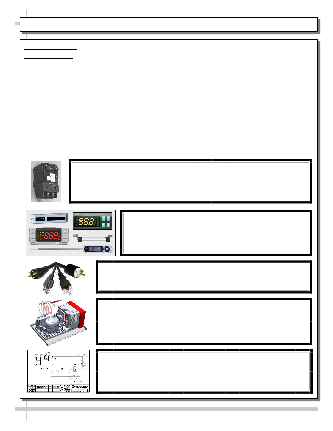
CAUTION! BREAKER USE REQUIREMENT
N.E.C. (National Electric Code) or local code requires dedicated breaker.
CAUTION! DO NOT RELY ON THERMOMETERS OR
THERMOSTATS FOR PRODUCT (FOOD) TEMPERATURES
• Thermometers & thermostats reflect air temperatures ONLY.
• For ACTUAL product (food) temperatures, use a calibrated food
probe thermometers ONLY.
• For accurate readings, DO NOT use infrared food thermometers.
7
OVERVIEW, CONT’D
QUALIFICATION OF WORKING PERSONNEL
• When performing maintenance, service and repair
on units with FLAMMABLE REFRIGERANTS, there
are specific requirements for persons carrying out
such tasks.
• Read specifics below.
SERVICING UNITS WITH FLAMMABLE REFRIGERANTS
• Read specifics below.
WORK PROCEDURE / GENERAL WORK AREA
• Read specifics below.
CHECKING REFRIGERANT / FIRE EXTINGUISHER
• Read specifics below.
> See next page for continuation.
OVERVIEW, CONT’D: QUAL. OF WKG PERS., SAF. CHECKS, WORK PROC., FIRE EXT. - PAGE 5 of 9
QUALIFICATION OF WORKING PERSONNEL
• Only authorized, approved, competent personnel should provide maintenance,
service and repair to cases with FLAMMABLE REFRIGERANTS.
• Every working procedure that affects safety means shall ONLY be carried out by
competent persons according to UL Annex 101.DVT (the section pertaining to
competence of service personnel).
• Per Annex 101.DVT, training should include the substance of the following:
> Information about explosion potential of FLAMMABLE REFRIGERANTS.
> Information about potential ignition sources (especially the inconspicuous
such as lighters, light switches, vacuum cleaners, electric heaters).
> Information about safety concepts such as leaky refrigerant issues,
unventilated vs ventilated enclosures and rooms.
> Information about refrigerant detectors.
> Information about the concept of sealed components and sealed enclosures.
> Information about correct working procedures, including commissioning,
maintenance, repair, decommissioning and disposal.
• Training must be conducted by national training organizations or manufacturers
that are accredited to teach relevant national competency standards that may be
set in legislation. Competency to be documented by an achievement certificate.
SERVICING UNITS WITH FLAMMABLE REFRIGERANTS
• Prior to beginning work on systems containing FLAMMABLE REFRIGERANTS, safety
checks are necessary to ensure that the risk of ignition is minimized.
WORK PROCEDURE / GENERAL WORK AREA
• Work shall be under a controlled procedure so as to minimize the risk of a
flammable gas or vapor being present while the work is being performed.
• All maintenance staff (and others working in the local area) shall be instructed on
the nature of work being carried out. Work in confined spaces shall be avoided.
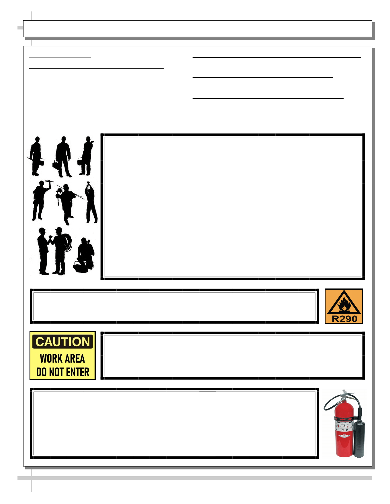
CHECKING FOR REFRIGERANT / FIRE EXTINGUISHER ACCESS
• The area shall be checked with appropriate refrigerant detector prior to and during work,
to ensure the technician is aware of potentially toxic or flammable atmospheres.
• Personnel must ensure that leak detection equipment being used is suitable for use with
all applicable refrigerants, i.e., non-sparking, adequately sealed or intrinsically safe.
• If any ‘hot work’ is to be conducted on refrigerant equipment (or any associated parts),
appropriate fire extinguishing equipment shall be available on hand. A dry chemical or
CO
2
fire extinguisher should be adjacent to the charging area.
8
OVERVIEW, CONT’D: IGNIT. SOURCES, VENTIL. AREA, REF. EQUIP & ELEC DEV. CHK - PAGE 6 of 9
OVERVIEW, CONT’D
NO IGNITION SOURCES
• Read specifics below.
VENTILATED AREA
• Read specifics below.
CHECKS TO REFRIGERATING EQUIPMENT
• Read specifics below.
CHECKS TO ELECTRICAL DEVICES
• Read specifics below.
> See next page for continuation.
NO IGNITION SOURCES
• No person carrying out work in relation to a REFRIGERATING SYSTEM which
involves exposing any pipe work shall use any sources of ignition in such manner
that it may lead to the risk of fire or explosion. All possible ignition sources,
including cigarette smoking, should be kept sufficiently far away from site of
installation, repairing, removing and disposal, during which refrigerant can
possibly be released to the surround space.
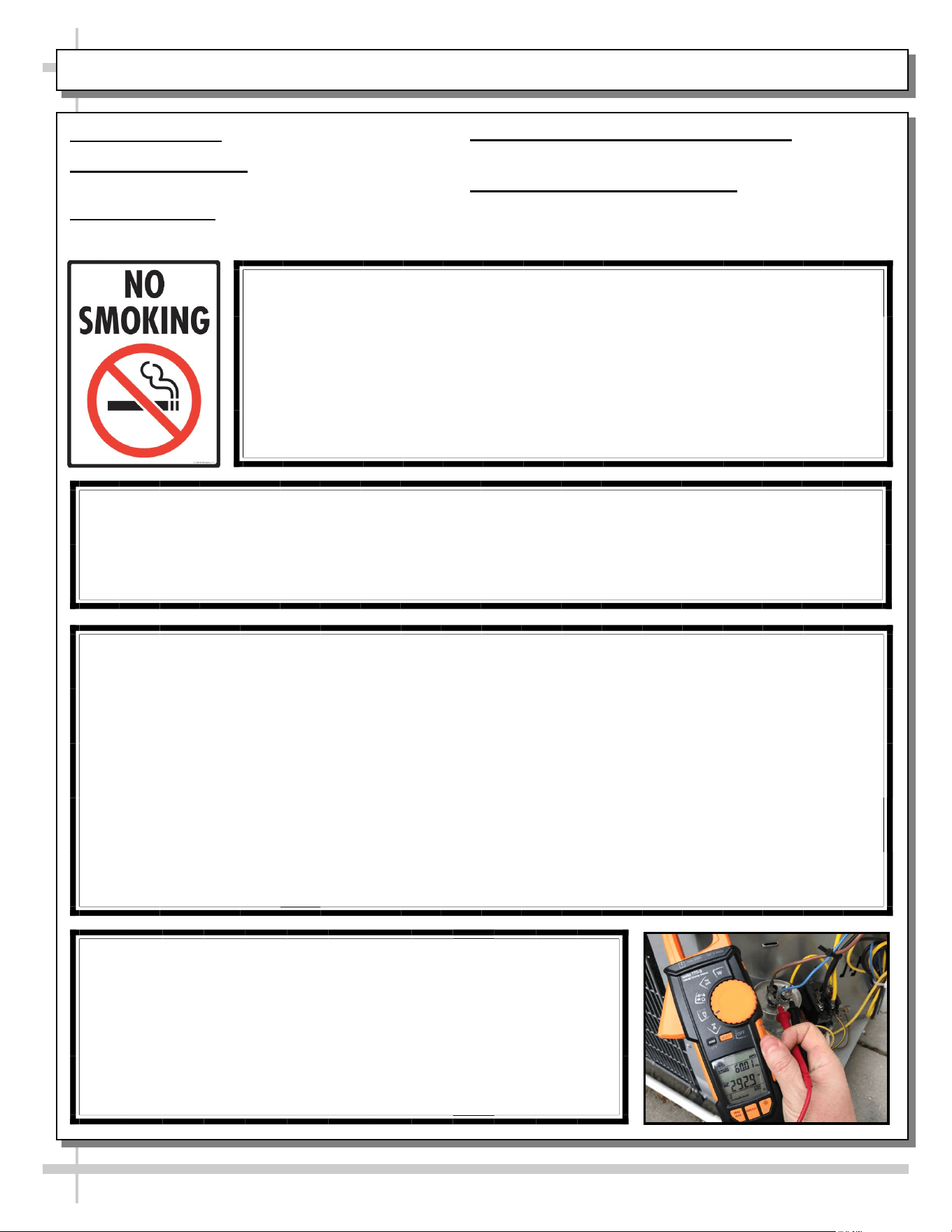
• Prior to work taking place, the area around the equipment shall be surveyed to
make sure there are no flammable hazards or ignition risks. “No Smoking” signs
shall be displayed.
VENTILATED AREA
• Ensure that the area is in the open or that it is adequately ventilated before breaking into the system or
conducting any ‘hot work.’
• A degree of ventilation shall continue during the period that the work is carried out. The ventilation
should safely disperse any released refrigerant and preferably expel it externally into the atmosphere.
CHECKS TO REFRIGERATING EQUIPMENT
Where electrical components are being changed, they shall be fit for the purpose and to the correct
specification. The manufacturer’s maintenance and service guidelines shall be followed at all times. If in
doubt, consult the manufacturer’s technical department for assistance. The following checks shall be
applied installation using FLAMMABLE REFRIGERANTS:
a) The actual REFRIGERANT CHARGE is in accordance with the room size within which the refrigerant
containing parts are installed.
b) The ventilation machinery and outlets are operating adequately and are not obstructed.
c) If an indirect refrigerating circuit is being used, the secondary circuit shall be checked fo the presence
of refrigerant.
d) Marking to the equipment continues to be visible and legible. Markings and signs that are illegible
shall be corrected.
e) Refrigerating pipe or components are installed where they are unlikely to be exposed to any substance
which may corrode refrigerant containing components, unless the components are constructed of
materials which are inherently resistant to being corroded or suitably protected against being corroded.
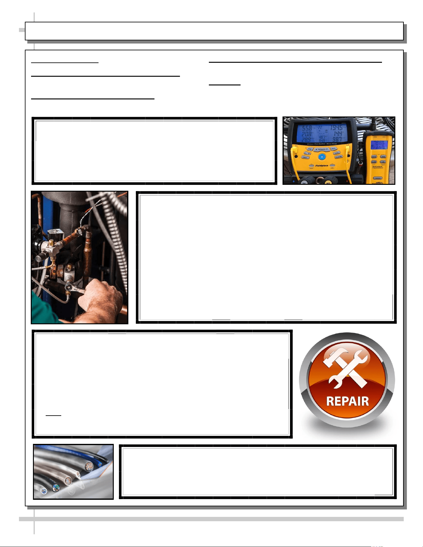
CHECKS TO ELECTRICAL DEVICES
• Repair and maintenance to electrical components shall include initial
safety checks and component inspection procedures. If a fault exists
that could compromise safety, then no electrical supply shall be
connected to the circuit until it is satisfactorily resolved. If the fault
cannot be corrected immediately but is necessary to continue
operation, an adequate temporary solution shall be employed.
• This shall be reported to the owner of the equipment so all parties
are advised.
9
OVERVIEW, CONT’D: ELEC. DEV. CHK, CONT’D, SEALED COMP., INT. SAFE COMP. CHK - PAGE 7 of 9
OVERVIEW, CONT’D
CHECKS TO ELECTRICAL DEVICES, CONT’D
• Read specifics below.
REPAIRS TO SEALED COMPONENTS
• Read specifics below.
REPAIRS TO INSTRINSICALLY SAFE COMPONENTS
• Read specifics below.
CABLING
• Read specifics below.
> See next page for continuation.
REPAIRS TO SEALED COMPONENTS
• During repairs to sealed components, all electrical supplies shall be
disconnected from the equipment being worked upon prior to any
removal of sealed covers, etc.
• If it necessary to have an electrical supply to equipment during servicing,
then a permanently operating form of leak detection shall be located at
the most critical point to warn of a potentially hazardous situation.
• Particular attention shall be paid to the following to ensure that by
working on electrical components, the casing is not altered in a manner
that the level of protection is affected. This shall include damage to
cables, excessive number of connections, terminals not made to original
specification, damage to seals, incorrect fitting of glands, etc. Ensure
that the apparatus is mounted securely.
• Ensure that seals or sealing materials have NOT degraded to the point
of no longer preventing the ingress of flammable atmospheres.
Replacement parts shall be per the manufacturer’s specifications.
REPAIRS TO INTRINSICALLY SAFE COMPONENTS
• Do not apply any permanent inductive or capacitance loads to the circuit
without ensuring that this will not exceed the permissible voltage and
current permitted for the equipment in use.
• Intrinsically safe components are the only types that can be worked on
while live in the presence of a flammable atmosphere. The test apparatus
shall be at the correct rating.
• Replace components ONLY with parts specified by the manufacturer.
Other parts can result in the ignition in the atmosphere from a leak.
• Note: The use of silicon sealant can inhibit the effectiveness of some
types of leak detection equipment intrinsically safe components do not
have to be isolated prior to working on them.
CABLING
• Check that cabling will NOT be subject to wear corrosion, excessive pressure,
vibration, sharp edges, or any other adverse environmental effects.
• The check shall also take into account the effects of aging or continual
vibration from sources such as compressors or fans.
CHECKS TO ELECTRICAL DEVICES, CONT’D
• Initial safety checks shall include:
a) that capacitors are discharged: this shall be done in a safe
manner to avoid possibility of sparking;
b) that no live electrical components are wiring are exposed while
charging, recovering or purging the system;
c) that there is continuity of earth bonding.
10
OVERVIEW, CONT’D: DETECTION OF FLAMM. REFRIG., REMOVAL AND EVACUATION - PAGE 8 of 9
OVERVIEW, CONT’D
DETECTION OF FLAMMABLE REFRIGERANTS
• Read specifics below.
REMOVAL AND EVACUATION
• Read specifics below.
> See next page for continuation.
DETECTION OF FLAMMABLE REFRIGERANTS
• Under no circumstances shall potential sources of ignition be used in
the searching for (or detection of) refrigerant leaks. A halide torch
(or any other detector using a naked flame SHALL NOT be used.
• The following leak detection methods are deemed acceptable for all
refrigerant systems.
• Electronic leak detectors may be used to detect refrigerant leaks but, in
the case of FLAMMABLE REFRIGERANTS, the sensitivity might not be
adequate, or might need recalibration. (Detection equipment shall be
calibrated in a refrigerant-free area). Ensure that the detector is not a
potential source of ignition and is suitable for the refrigerant used.
• Leak detection equipment shall be set at a percentage of the LFL of the
refrigerant and shall be calibrated to the refrigerant employed, and the
appropriate percentage (25% maximum) of gas is confirmed.
• Leak detection fluids are also suitable for use with most refrigerants but
the use of detergents containing chlorine shall be avoided as the
chlorine can react with the refrigerant and corrode the copper pipe-work.
• Examples of leak detection fluids are a) bubble method and
b) fluorescent method agents.
• If a leak is suspected, all naked flames shall be removed/extinguished.
• If a leakage of refrigerant is found which requires brazing, all refrigerant
shall be recovered from the system or isolated (by means of shut-off
valves) in a part of the system remove from the leak. Removal of
refrigerant shall be according to UL Annex Clause 101.DVS.9.
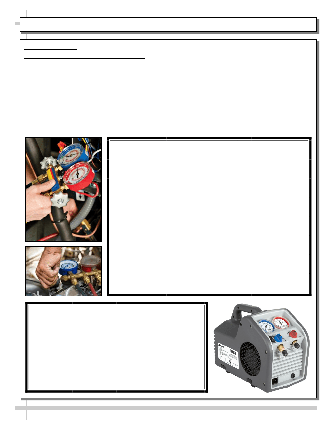
REMOVAL AND EVACUATION
• When breaking into the refrigerant circuit to make repairs (or
for any other purpose) conventional procedures shall be used.
However, for flammable refrigerants, best practice MUST be
followed, since flammability is a consideration.
• The following procedures shall be adhered to:
a) safely remove refrigerant following local and national
regulations; b) purge the circuit with inert gas; c) evacuate
(optional for A2L); d) purge with inert gas (optional for A2L)
e) open the circuit by cutting or brazing.
• The refrigerant charge shall be recovered into the correct
recovery cylinders if venting is not allowed by local and
national codes.
11
OVERVIEW, CONT’D: REMOVAL AND EVACUATION, CHARGING PROCEDURES - PAGE 9 of 9
OVERVIEW, CONT’D
REMOVAL AND EVACUATION, CONT’D
• Read specifics below.
CHARGING PROCEDURES
• Read specifics below.
> See next page for continuation.
REMOVAL AND EVACUATION, CONT’D
• For cases containing flammable refrigerants, the system shall be
purged with oxygen-free nitrogen to render the unit safe for
flammable refrigerants. This process might need to be repeated
several times. Compressed air or oxygen shall not be used for
purging refrigerant systems.
• For case containing flammable refrigerants, refrigerants purging
shall be achieved by breaking the vacuum in the system with
oxygen-free nitrogen and continuing to fill until the working
pressure is achieved, then venting to atmosphere, and finally
pulling down to a vacuum (optional for A2L).
• This process shall be repeated until no refrigerant is within the
system (optional for A2L). When the final oxygen-free nitrogen
charge is used, the system shall be vented down to atmospheric
pressure to enable work to take place.
• Ensure that the outlet for the vacuum pump is not close to any
potential ignition sources and that ventilation is available.
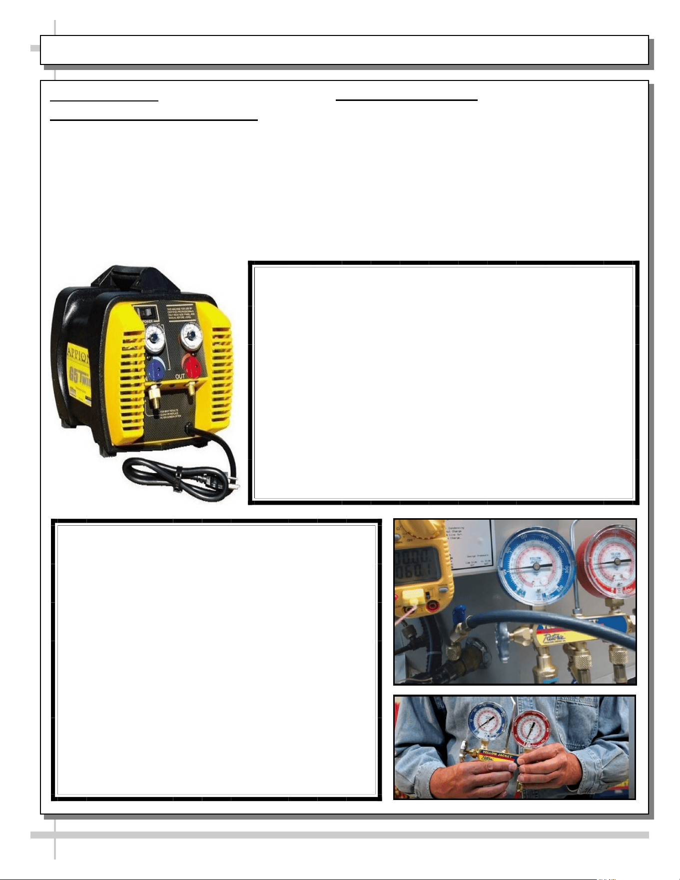
CHARGING PROCEDURES
In addition to conventional charging procedures, the
following requirements shall be followed.
a) Ensure that contamination of different refrigerants
does not occur when using charging equipment. Hoses or
lines shall be as short as possible to minimize the amount
of refrigerant contained in them.
b) Cylinders shall be kept in an appropriate position
according to the instructions.
c) Ensure that the REFRIGERATION SYSTEM is searched
prior to charging the system with refrigerant.
d) Label the system when charging is complete (if not
already.
e) Extreme care shall be taken not to overfill the
REFRIGERATING SYSTEM.
• Prior to recharging the system, it shall be
pressure-tested with the appropriate purging gas.
• The system shall be leak-tested on completion of
charging but prior to commissioning.
• A follow-up leak test shall be carried out prior to
leaving the site.
12
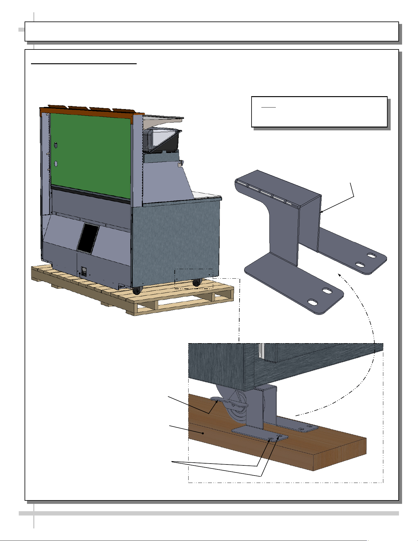
INSTALLATION: REMOVAL OF CASTER BRACKETS FROM SKID
1. Remove Caster Brackets
• Caster brackets secure case to skid during shipment
• Remove caster bracket retaining screws.
• Remove caster brackets from skid. Discard/recycle.
Sample Caster With Lock/Unlock
Capability. Note: Your Caster Locking
System May Differ.
Caster Bracket Shown After
Removal From Skid (Typ.)
Caster Bracket
Retaining Screws (Typ.)
Small Section of Skid
Board (Typ.)
Note: Illustration shown reflects model
FBR6S-5R.8110. It may not reflect every
feature or option of your particular model.
13
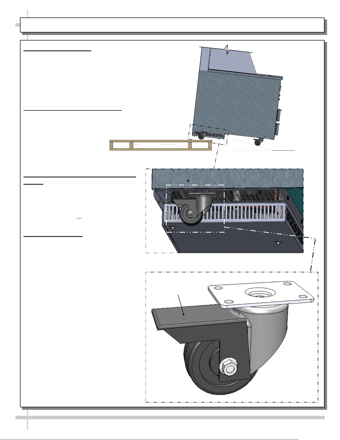
INSTALLATION, CONT’D: CASE REMOVAL FROM SKID / POSITIONING / CASTER LOCKING
2. Unlocking Casters
• Important! Cases are shipped with casters in
LOCKED position (for stability).
• All casters must be UNLOCKED before moving unit
off skid and into position.
• After levelers are unlocked, place ramp up
against skid (to allow case to smoothly roll off
from skid).
3. Roll Case Off Skid via Ramp
• Maintain support of case at all times or
center of gravity may cause case to fall.
• Roll unit to rear of skid.
• Check that ramp is secure
and possibly even attached
to skid with screws.
• Carefully roll down ramp and
off skid.
4. Position & Align Alongside Other
Cases
• Before locking casters again, make certain
that the case is in proper position and, if
required, aligned with adjoining case(s).
• This may require repositioning of the case
you are installing or the already positioned
cases.
5. Locking Casters
• Press down on caster lock to secure in place.
• Raise caster lock to allow casters to turn
freely.
• See illustration at lower-right for sample
locking caster.
--- Rotated Underside View of Model FBR6S-5R.8110 ---
Raise To Unlock /
Press Down To Lock
14
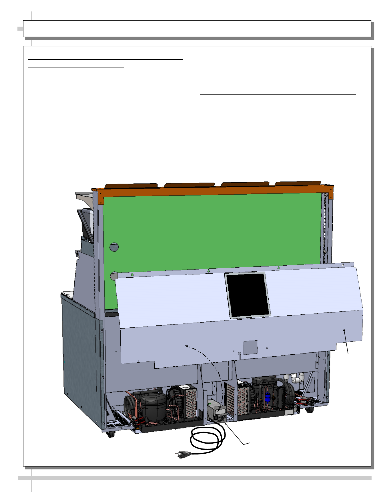
INSTALLATION, CONT’D: CONNECTIONS CHECK / REATTACH PANEL / TURNING ON POWER TO CASE
6. Check Condenser Package Connections
Before Powering Up Case!
• Caution! Connections can come loose during
shipment; this can allow water to overflow
onto floor, causing damage!
• When case in is proper location, remove rear
panel to check for loose connections.
• Rear panel can be removed by removing screws,
grasping panel and pulling outward and off.
• Place away from foot traffic while checking
connections.
• See TROUBLESHOOTING section in operating
manual for various troubleshooting issues.
• Return rear panel to case in reverse order it was
removed.
7. Reattach Panel / Turn On Power To Case
• Return rear panel to case.
• Plug in power cord.
• Turn on main power switch (at rear center).
• Check that programmable controller is energized.
• Check that case is energized and that evaporator
fans are rotating.
Electrical Box
(Main Power Switch /
Thermostat / LED Driver)
Power Cord
Rear
Panel
15
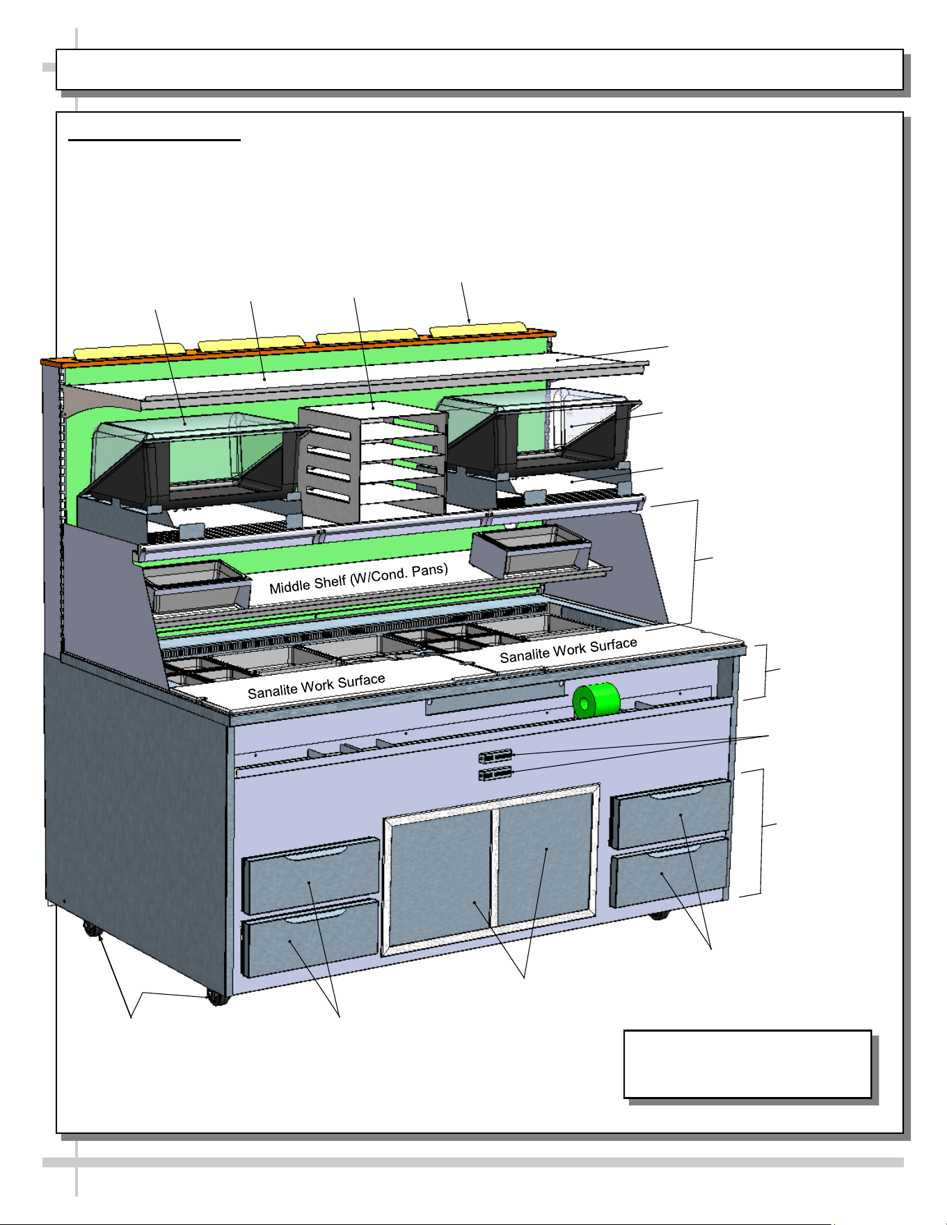
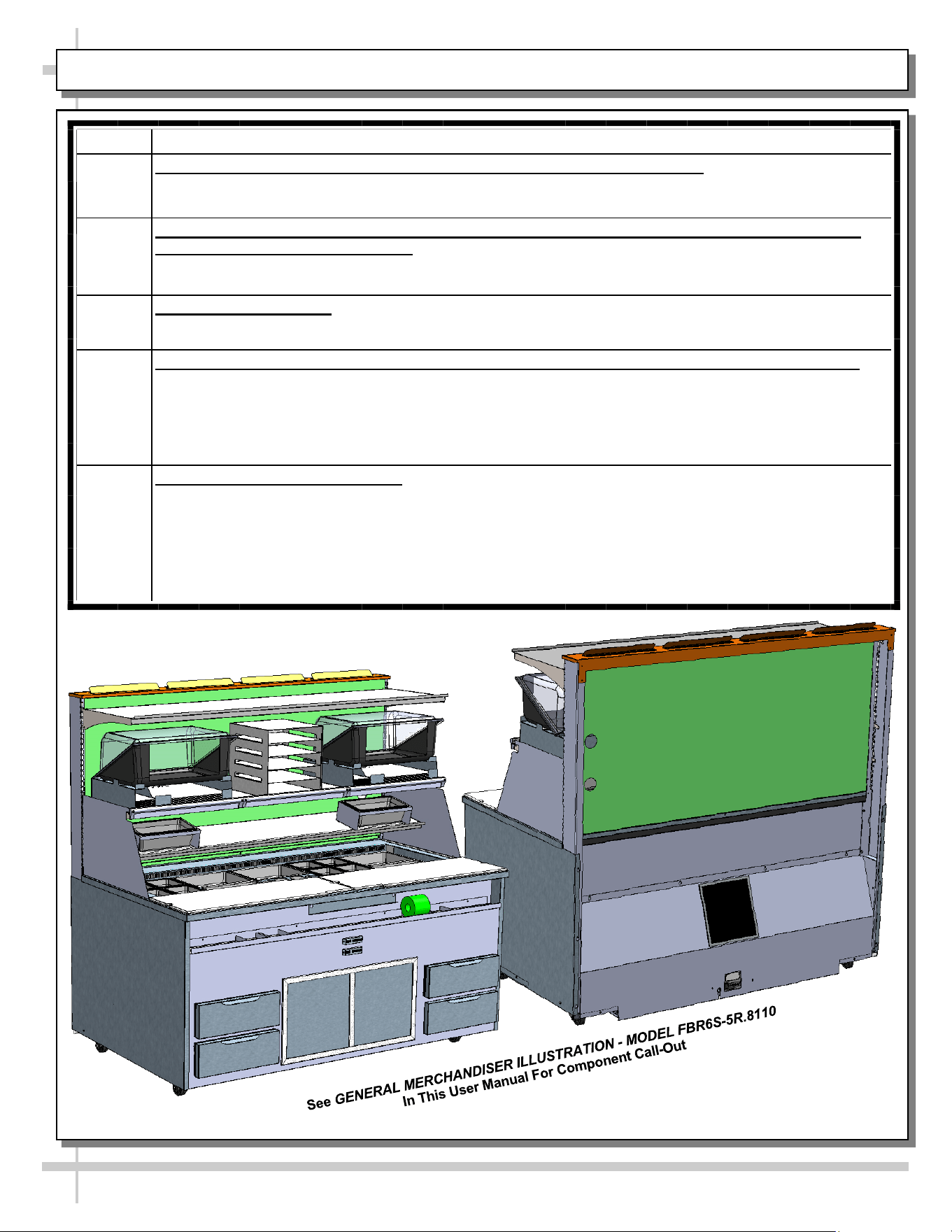
GENERAL MERCHANDISER ILLUSTRATION - MODEL FBR6S-5R.8110 - PAGE 1 of 7
1. Front View of Case
• Components are called out based on factory specifications.
• Your particular store’s layout/design may differ than illustration shown.
>> See next page for continuation.
Model FBR6S-5R.8110 Is
Shown. It May Not Reflect Every
Feature or Option of Your
Refrigerated
Drawers (Typ.)
Refrigerated
Drawers (Typ.)
Casters (Typ.)
Sliding Doors
(To Refrigerated
Cubby Area)
Thermometers
To Upper and
Lower Sections
Channel: Label
& Glove Box
Holder
Lower
Refrigerated
Section
Upper
Refrigerated
Section
Clam Bin
Clam Bin
Upper Shelf
Upper Shelf
Chimney
Paper Bin
(Step)
Bag/Paper & Holder (Typ.)
16
GENERAL MERCHANDISER ILLUSTRATION - MODEL FBR6S-5R.8110 - PAGE 2 of 7
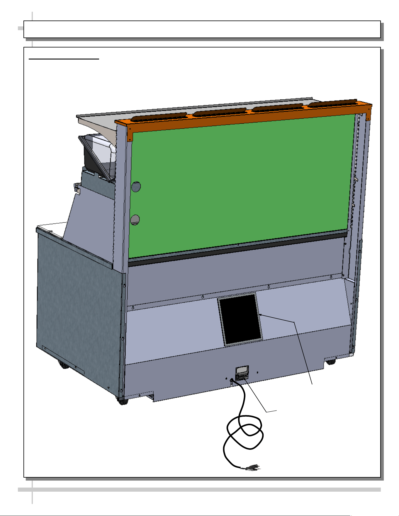
2. Rear View of Case
• Main power switch and thermostat is at case rear (rear panel does NOT need to be removed to access
thermostat).
• See illustration below.
Main Power Switch
and Thermostat
Power Cord
Filter
Condenser
Package
17
GENERAL MERCHANDISER ILLUSTRATION - MODEL FBR6S-5R.8110 - PAGE 3 of 7
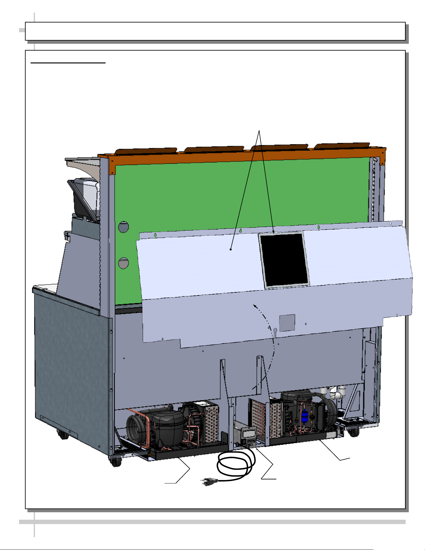
3. Rear View of Case
• Rear panel is shown removed to show access to condenser package and electrical box.
• Electrical box contains the main power switch, thermostat, LED driver, etc.
>> See next page for continuation.
Condenser
Package
Electrical Box
(Main Power Switch /
Thermostat / LED Driver)
Rear Panel & Magnetic Air Filter
Power Cord
18
GENERAL MERCHANDISER ILLUSTRATION - MODEL FBR6S-5R.8110 - PAGE 4 of 7
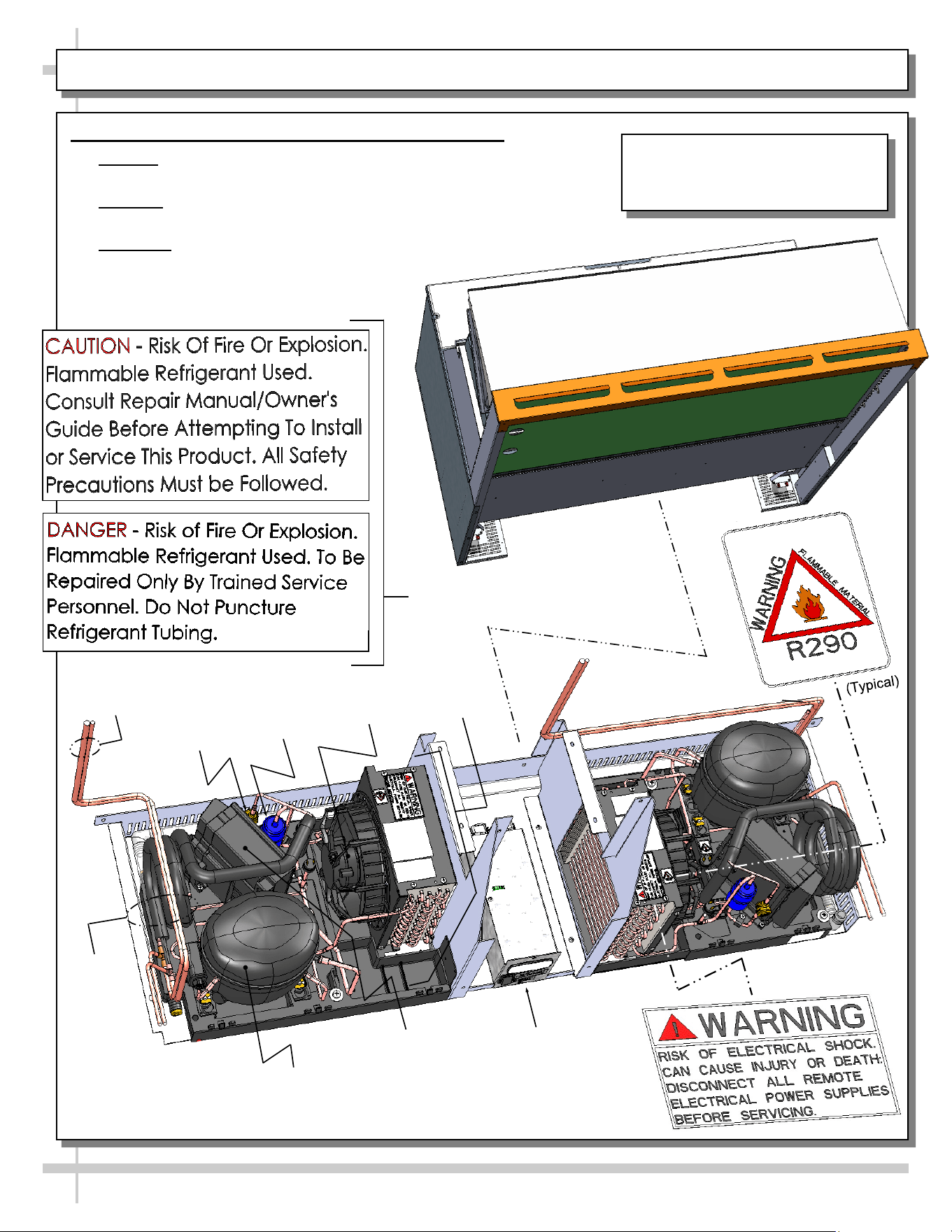
4. Self-Contained Hot Gas Loop Condensate Package
• Caution: Only trained service providers are to provide
maintenance and service to unit.
• Warning! Disconnect power before providing maintenance and
service to unit.
• Important: Carefully read all Warning/Caution/Danger labels on unit!
>> See next page for continuation.
Model FBR6S-5R.8110 Is Shown.
It May Not Reflect Every Feature or
Option of Your Particular Case.
Compressor
Sight
Glass
Condenser
Fan & Housing
Refrigeration
Lines
Filter
Dryer
Courtesy
Loop
Compressor
Inverter
Electrical Box
(Main Power Switch
/ Thermostat /
LED Driver)
Condenser
Coil
Housing
Additional Caution / Danger Labels
19
GENERAL MERCHANDISER ILLUSTRATION - MODEL FBR6S-5R.8110 - PAGE 5 of 7
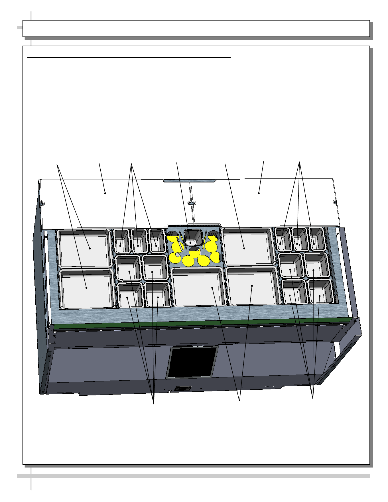
5. Product Pans & Mayo Pan Holder / Sanalite Work Surfaces
• Stainless steel product pans & mayo pan are removable from case (for cleaning and/or replacement).
• Sanalite work surfaces are also removable from case (for cleaning and/or replacement).
• See illustration below.
Small
Product
Pans
Large Product
Pans
Sanalite
Work
Surface
Medium
Product Pans
Small
Product
Pans
Large
Product Pan
Sanalite
Work
Surface
Medium
Product Pans
Large Product
Pans
Mayo Pan
20
GENERAL MERCHANDISER ILLUSTRATION - MODEL FBR6S-5R.8110 - PAGE 6 of 7
6. Product Pan Holders & Squeeze Bottle Dispenser Holders
• Stainless steel product pans & squeeze bottle dispenser holders are removable from case (for cleaning
and/or replacement).
• See illustration below for both intact and removed components (for illustrative purposes only).
Product Pan
Holder
Product Pan
Holder
Squeeze-Bottle
Dispenser & Mayo
Pan Holder
Product Pan
Holder
Product Pan
Holder
Product Pan
Holder
Discharge
Pans
Product Pan
Holder
Discharge
Pan
Discharge
Pan
Sample
Product Pan
Holder
(Shown
Removed)
Sample Discharge Pan
(Shown Removed)
21
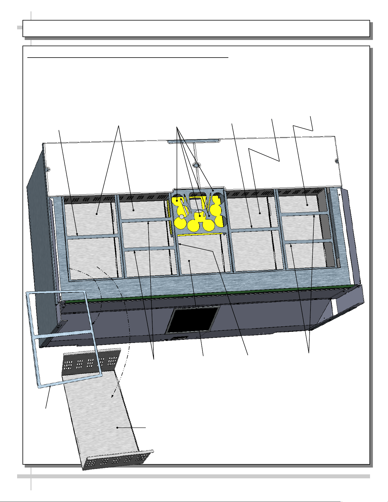
GENERAL MERCHANDISER ILLUSTRATION - MODEL FBR6S-5R.8110 - PAGE 7 of 7
7. Evaporator Coil Fans / Air Discharge
>> Illustration below is shown AFTER all product pan
holders and discharge pans have been removed.
>> When case is energized, refrigeration of unit is
operational.
• Evaporator coil fan should turn on.
• From inside of the case, check for discharge air
from honeycomb discharge duct to confirm that
the fan is functioning properly.
Drain
Trough
TXV
Evaporator
Fan Shroud
• When the case is in a start-up mode or has been
idle for a long period of time, the unit will require
75-minutes of run time to pull-down temperature.
8. TXV (Thermostatic Expansion Valve)
• Dual TXV system is utilized on this model.
• See illustration below for TXV locations.
Close-Off
TXV
Coil
Covers
Tub
Close-Off
Evaporator
Coil
Evaporator
Fan, Blades
& Cover
Evaporator
Coil
Evaporator
Fan Shroud
Tub
Trough
Evaporator
Fan, Blades
& Cover
22
CLEANING SCHEDULE - PERFORMED BY STORE PERSONNEL
FREQ. INSTRUCTIONS
Daily Inner Metal Components (Shelves, Decks, Rear Plenum, Acrylic Bins, Etc.):
• Wipe with cloth dipped in mild-soapy water. Dry with soft cloth.
Daily Outer Metal Components (Sliding Doors, Drawers, Rear Channel (For Labels), End Panels, Side
Air Deflectors, Rear Chimney, Etc.):
• Wipe with cloth dipped in mild-soapy water. Dry with soft cloth.
Daily Sanalite Cutting Boards:
• Wipe with cloth dipped in mild-soapy water. Rinse with spray bottle of pure water. Dry with soft cloth.
Weekly Sanalite Cutting Boards, Metal Work Surface, Rear Filter, Refrigerated Drawers and Cubby Area
• Sanalite cutting boards: Remove from case. Submerse Sanalite cutting boards in warm, soapy water
and clean with soft-bristled brush. Rinse. Dry with soft cloth. Return to its metal work surface (after it
has been cleaned).
• Metal work surface (at underside of Sanalite cutting boards), refrigerated drawers and cubby area
(accessible via center sliding doors): Wipe with cloth dipped in mild-soapy water. Dry with soft cloth.
Weekly Magnetic Air Filter (At Case Rear):
• Remove from case. As magnetic condenser coil filter is dishwasher safe, you may run it in normal
dishwasher cycle. Remove from dishwasher. Dry with soft cloth or paper towel. Return to case.
• If not using dishwasher, remove magnetic condenser coil filter from case. Use a rag or soft-bristled
brush to wipe off excess dust particles from filter. Submerse in warm, soapy water in sink. Use
soft-bristled brush to remove dust, dirt, grease and grime that may collect on filter. Rinse thoroughly.
• Reattach magnetic air filter to rear of case.
23
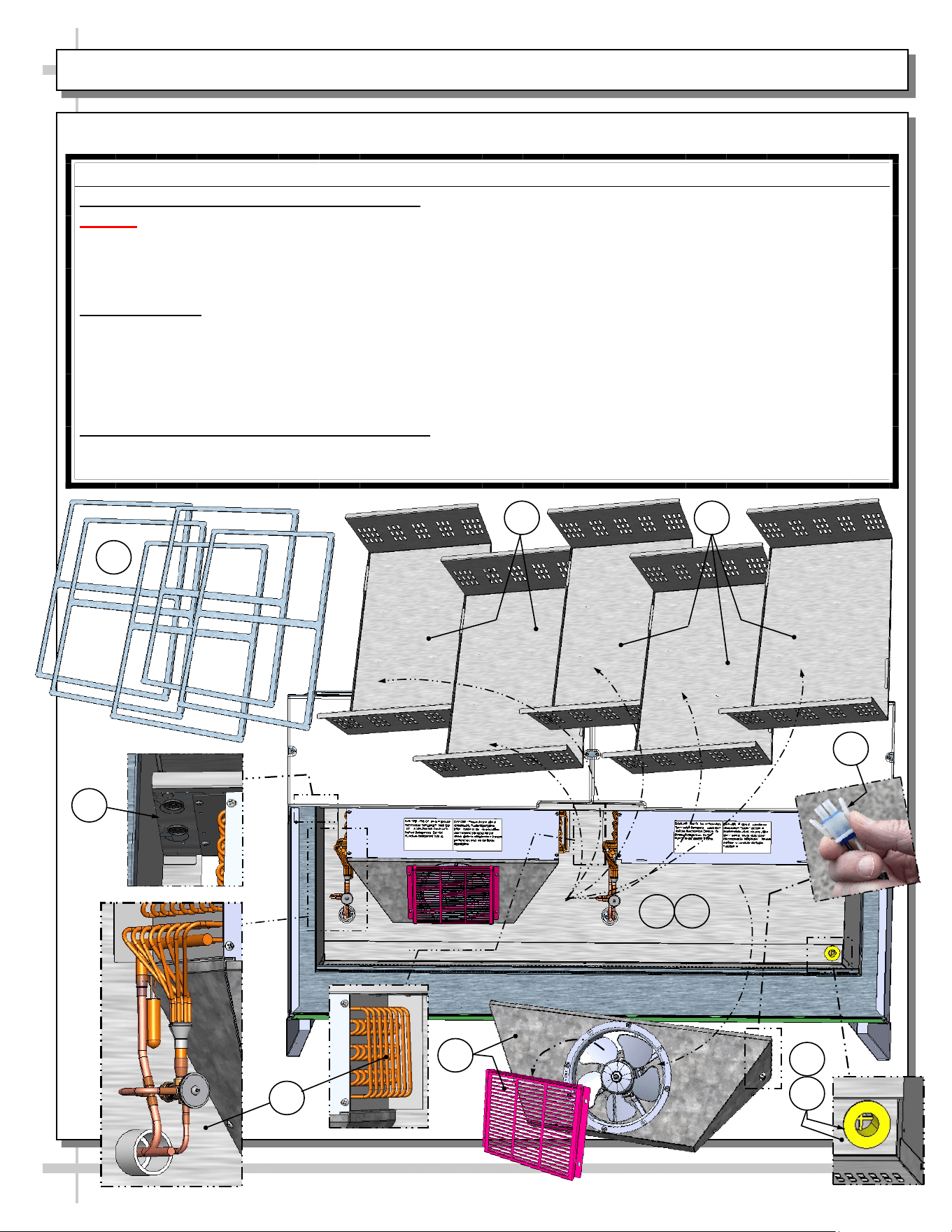
WARNING! TURN OFF CASE BEFORE PERFORMING PREVENTIVE MAINTENANCE!
QUARTERLY PREVENTIVE MAINTENANCE INSTRUCTIONS
Tub, Coil, Drain, Fan Blades, Motors, Brackets:
Caution! Turn Power Off To Case. Do Not Clean or Perform Service On Unit While Case Is Energized!
1. Remove product pan holders. Place in safe place away from foot traffic.
2. Remove discharge pans. Place in safe place away from foot traffic.
3. Disconnect power cord connectors that energizes fan assemblies.
4. Grasp fan shroud/fan cover assemblies. Lift up and away from case. Place in safe place away from foot traffic.
Cleaning Process:
A. Use vacuum to remove excessive residue AND to remove dust in tub, trough and drain.
B. Use clean cloth and/or nylon brush with warm water and mild soap solution to clean tub, drain, trough, TXV,
lines, solenoid, coil & coil tubes. See enlarged view of components to be cleaned (lower-right).
C. Use clean cloth with warm water and mild soap solution to clean fan covers, fans, fan blades, shrouds, etc.
D. Use clean cloth with warm water and mild soap solution to clean close-off areas.
>> Dry components with clean rag or paper towel.
Returning Components / Restoring Power To Case:
• Replace/reconnect components in reverse order they were removed or disconnected.
• Turn main power switch back on. Check that evaporator fans are operational.
PREVENTIVE MAINTENANCE - TO BE PERFORMED BY TRAINED SERVICE PROVIDERS ONLY - 1 of 2
3
B
2
A
D
2
1
C
A
B
B
24
WARNING! TURN OFF CASE BEFORE PERFORMING PREVENTIVE MAINTENANCE!
QUARTERLY PREVENTIVE MAINTENANCE INSTRUCTIONS, CONT’D
Under Case Cleaning:
• At either case front or rear, vacuum (or broom) under case to remove all dust, debris and dirt that
may collect.
• As case is on casters, you may need to unlock them and slightly move case out of position to access
desired areas to clean.
Condensate Package:
Caution! You must turn main power switch off before cleaning!
• Remove rear panel. Turn main power switch off and allow components to cool.
• Use a soft-bristled scrub-brush and non-corrosive de-scaling solution (to remove calcium, lime and
rust) from condensate pan. Wipe down courtesy loop. Follow de-scaling solution’s instructions as to
proper dilution and safety precautions.
• After thoroughly cleaning pan with brush and solution, rinse thoroughly with clean water
(in spray bottle) and wipe dry with sponge or paper towel.
• Use moist cloth to wipe off dust & debris that collects on various parts (hot gas loop condensate pan,
compressor fan, blades and housing, fans, sight glass (if any), refrigeration lines, courtesy loop,
overflow pan (if any), etc.
• Return front panel to case.
• See GENERAL MERCHANDISER ILLUSTRATION - MODEL FBR6S-5R.8110 - PAGE 4 of 7 in this
User Manual for condensate package illustration.
PREVENTIVE MAINTENANCE - TO BE PERFORMED BY TRAINED SERVICE PROVIDERS ONLY - 2 of 2
25
CONDITION TROUBLESHOOTING
Case Not
Lining Up
See INSTALLATION section in this manual for instructions on properly aligning case
(alongside other cases) and adjusting levelers.
Water Is On
The Floor
Caution! Water on flooring can cause much damage! Until cause is determined (and
repaired), follow these procedures:
• Use wet-dry vacuum (or mop & bucket) to remove standing water.
• Use ‘catch pans’ for water to drain into. Swap out regularly until case has completely
drained.
Check that the drain trap is free from debris.
Check that the drain hose/pipe is correctly positioned over condensate pan (or floor drain,
for remote units).
Check store conditions. To prevent condensation in NSF/ANSIType II environments,
conditions are to be 55% maximum humidity / 80° Fahrenheit (27° Celsius) maximum
temperature.
Check that condensate pan components have no loose connections.
Check that overflow condensate pan (if any) has its power cord plug properly plugged into
electrical box.
Check that overflow condensate pan (if any) is not malfunctioning. Its electric rod heater
should be heating up when case is energized.
Caution! Disruption of power can cause water to overflow pan and seep onto flooring
causing damage! Check that power to case is constant. Until power is restored, follow
these procedures:
• Use wet-dry vacuum (or mop & bucket) to remove standing water.
• Use ‘catch pans’ for water to drainage. Swap out regularly until drainage of case is
complete (or until power is restored).
• When power to case is restored, condensate pan should function properly and water
will no longer overflow onto flooring.
TROUBLESHOOTING (TO BE PERFORMED BY TRAINED SERVICE PROVIDER ONLY) - PAGE 1 of 3
26
CONDITION TROUBLESHOOTING
Fan Emits Excessive
Noise
Check that the case is aligned, level and plumb.
Check evaporator fan for cleanliness.
Unplug/power off fan motor. Check motor shaft for bearing wear.
Check that fan motor is securely mounted in brackets.
Verify that fan blades are securely mounted to fan motor.
Check that nothing is preventing blade rotation.
Check that the fan shroud is properly secured.
Fan Is Not Working Check that the MAIN power switch is on.
Check that fan connector is securely plugged in at fan shroud.
Check that fan connector is securely plugged in near close-off.
Check for foreign material obstructing fan performance.
Check that fan blade freely rotates within fan shrouds
Check that power is going to fans
Check that fan wiring is connected on terminal blocks.
Programmable
Controller Display
Is Blank
Check that the MAIN power switch is on.
Check circuit breaker box for tripped circuits.
Programmable
Controller Display Is
Flashing
See your case’s serial label for your model’s specified settings. See SERIAL
LABEL LOCATION & INFORMATION LISTED / TECH INFO & SERVICE for
label location, etc.
System Not Operating Check that the utility power is on.
Check that the MAIN power switch is on.
Check the circuit breaker box for tripped circuits.
TROUBLESHOOTING (TO BE PERFORMED BY TRAINED SERVICE PROVIDER ONLY) - PAGE 2 of 3
27
CONDITION TROUBLESHOOTING
Case Is Not Holding
Temperature
If a large amount of warm product was added to the case, it will take time for the
temperature to adjust. Please load case with pre-chilled product.
Check that case is not directly in the sun.
Check that condenser coil has been cleaned.
Check air return opening for obstructions.
Check sight glass for flashing and/or low charge.
Check set point temperature; it may be adjusted too high.
Condensing Unit Is
Not Operating
Check that the power is turned on.
Check if programmable controller settings are properly set. See your case’s serial
label for your model’s specified settings. See SERIAL LABEL LOCATION &
INFORMATION LISTED / TECH INFO & SERVICE section in manual for label
location, etc.
TROUBLESHOOTING (TO BE PERFORMED BY TRAINED SERVICE PROVIDER ONLY) - PAGE 3 of 3
28
CONDITION TROUBLESHOOTING
Head Pressure Too
High
Check that the condensing coil is not dirty or covered.
Check that condensing fans are working.
Perform sub-cooling check and verify that no contaminates are in system.
Check that liquid line filter dryer is not plugged.
Check that close-offs are intact (around condensing coil) and that air is not recir-
culating.
Check that store ambient temperature isn’t above maximum allowed.
See OVERVIEW / TYPE / COMPLIANCE / WARNINGS / PRECAUTIONS /
WIRING / PLUGS section in this manual.
Head Pressure Too
Low
If sight glass is part of condensing unit, check if it is flashing or showing low charge.
TROUBLESHOOTING - R-290 CONDENSING SYSTEM (BY TRAINED SERVICE PROVIDERS ONLY)
29
CONDITION TROUBLESHOOTING
Low Suction
Pressure
Check if sight glass (if present) is flashing or showing low charge.
Check that expansion valve (TXV) isn’t restricted. Check element charge.
Check that liquid line or filter isn’t restricted. Check that refrigeration line / courtesy
loop is not kinked.
Check that evaporator fan motor is working.
Check that superheat is between 6 °F to 8 °F (-14 °C to -13 °C).
Check that there is no air recirculation around evaporator coil.
Check that evaporator coil is not iced up.
High Suction
Pressure
Check that the “cooling load” isn’t high. Product must be pre-chilled before placing
in refrigerated section of case.
Check that case is at least 15-feet from exterior doors, overhead HVAC vents or
any air curtain disruption.
Check that unit is not exposed to direct sunlight via windows or any other heat
source (ovens, fryers, etc.).
Check that superheat adjustment isn’t low.
Check TXV bulb installation
a. Poor thermal contact.
b. Warm location.
TROUBLESHOOTING - R-290 EVAPORATOR SYSTEM (BY TRAINED SERVICE PROVIDERS ONLY)
30
SERIAL LABEL LOCATION & INFO LISTED / TECH INFO & SERVICE / REFRIGERATED CASES ONLY
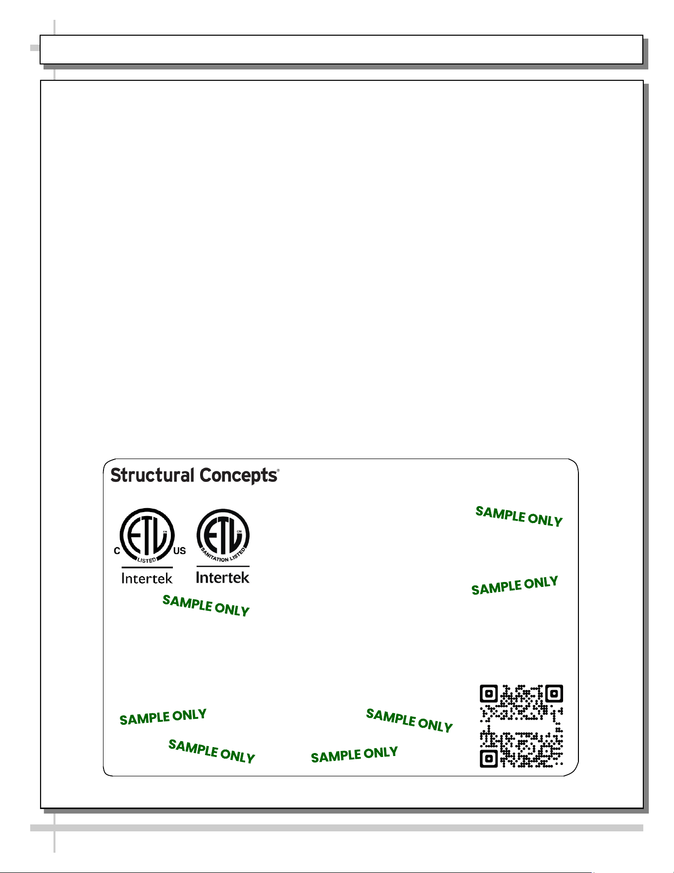
--- Sample Serial Label For Refrigerated Cases ---
MODEL NRS3648RXV-SAMPLE
SERIAL NO. 12345X30DZ098765
888 E. Porter Rd - Muskegon, MI 49441
3048256
Conforms to UL Std. 471
Conforms to NSF/ANSI Stds. 2 & 7
CERTIFIED TO CAN/CSA
STD C22.2 NO 120
ELECTRICAL RATING
REFRIGERANT
DESIGN PRESSURE
MINIMUM CIRCUIT AMPACITY
MAXIMUM OVERCURRENT
120/1/60 16 A
R513A AMOUNT 50 OZ
HIGH 186 LOW 88
20A
20A
Super Heat Temp 6-8 °F FOR PARTS AND SERVICE
Defrost 6 defrosts per day, 45 °F CALL 1-800-433-9490
Serial Label Location & Information Listed /
Technical Information & Service
• Serial labels are affixed at a wide range of places
(on the header, near thermostat, at case rear,
behind panels/toe-kicks, on electrical boxes, etc.).
• Serial labels contain electrical, temperature and
refrigeration information, as well as regulatory
standards to which the case conforms.
• Sample serial label is shown. A variety of models is
displayed on serial label for illustration purposes only.
Your case’s serial label will reflect only one model.
• For additional technical information and service, see
the TECHNICAL SERVICE page in this manual for
instructions on contacting Structural Concepts’
Technical Service Department.
Reveal
Harmony
Fusion
Impulse
Addenda
Blend
Grocerant
Oasis
Sample QR Code
SCAN FOR PRODUCT LITERATURE
SAMPLE ONLY
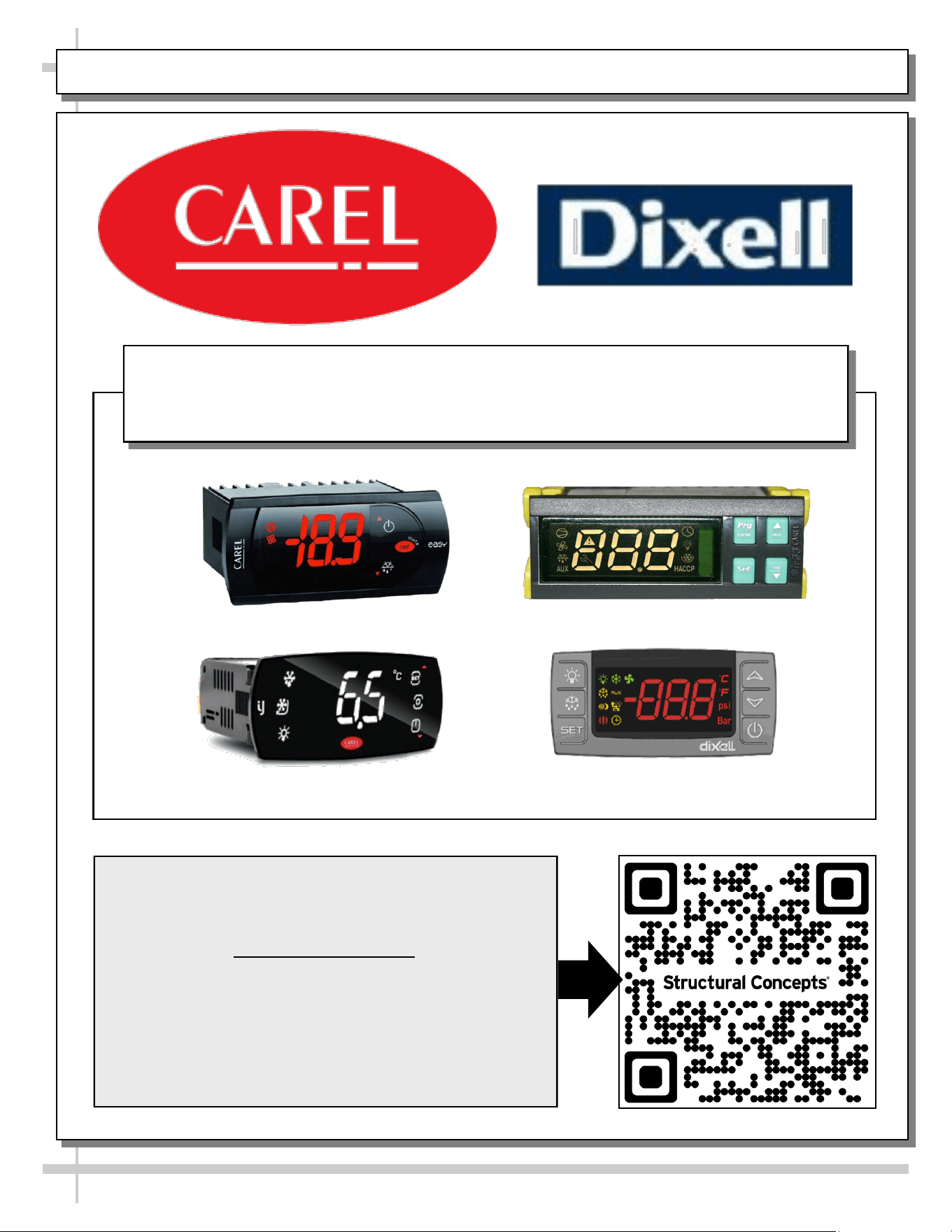
PROGRAMMABLE CONTROLLER (SELECT, CLICK ON OR SCAN QR CODE FOR INFORMATION)
31
Carel® iJF Platform
Carel® PJEZ Platform
Carel® ir33 Platform
Dixell® XM670K-XM679K Platform
To Access Information About The Programmable
Controller That Is Used On Your Case,
Follow These Instructions:
> If Viewing This Document on Smart Phone, Tablet
or Computer, Select/Click On The QR Code at Right.
> If Viewing This Document In Print (Hard Copy),
Scan The QR Code at Right With Your Smart Phone
or Tablet.
Determine Which Programmable Controller Is On Your Case (Controllers
That Are Commonly Used By Structural Concepts Are Shown Below).
Your Particular Programmable Controller May Differ From Units Shown.
STRUCTURAL CONCEPTS TECHNICAL SERVICE CONTACT INFORMATION & LIMITED WARRANTY
32
TECH SERVICE/WARRANTY CONTACT INFO:
1 (800) 433-9490 / EXTENSION 1
DAYS/HOURS AVAILABLE:
MONDAY - FRIDAY (CLOSED HOLIDAYS)
8:00 AM to 8:00 PM EST
YOU MUST HAVE THE FOLLOWING INFO AVAILABLE
BEFORE CONTACTING STRUCTURAL CONCEPTS:
SERIAL NO. / MODEL NO. / STORE NO. / STORE
ADDRESS / DETAILS (PHOTOS, LEAK LOCATIONS,
DAMAGE, STORE’S AMBIENT CONDITIONS, ETC.)
To Access The Limited Warranty To Your
Case, Follow These Instructions:
> If Viewing This Document on Smart Phone,
Tablet or Computer, Select/Click On The QR
Code at Right.
> If Viewing This Document In Print (Hard
Copy), Scan The QR Code at Right With Your
Smart Phone or Tablet.
