
FiberSource CMY150
user manual
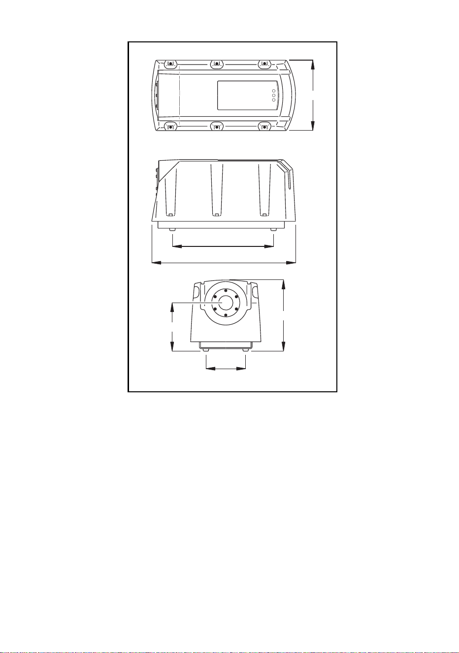
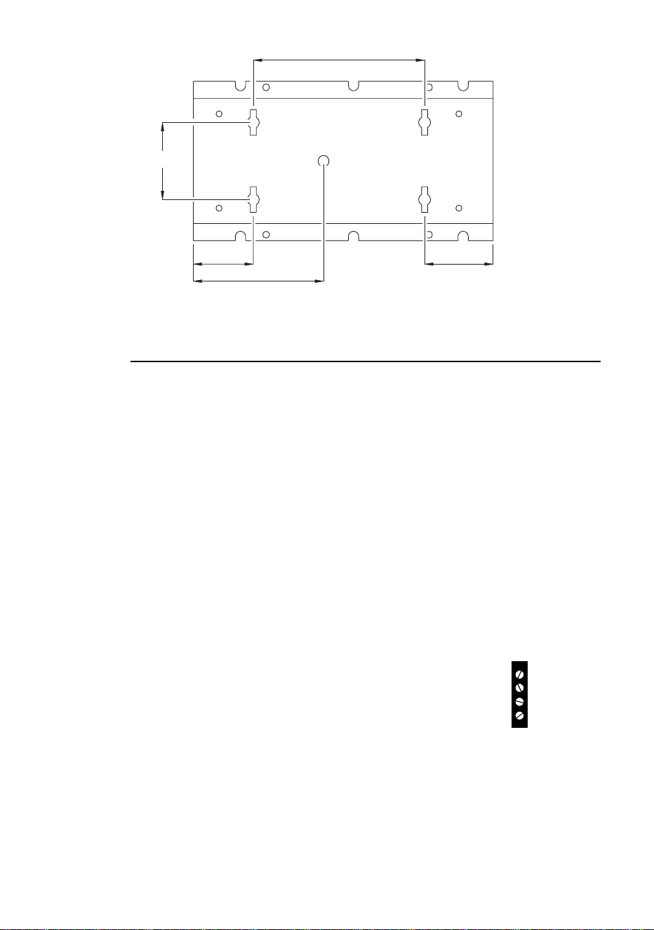
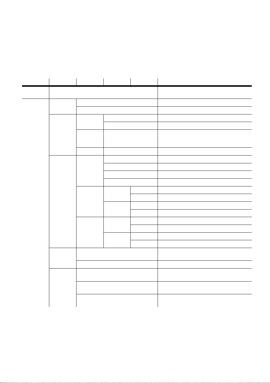
Measurements are in millimeters.
280
110
197
134
398
195
© 2001-2006 Martin Professional A/S, Denmark.
All rights reserved. No part of this manual may be reproduced, in any form or by any means, with-
out permission in writing from Martin Professional A/S, Denmark.
Printed in Denmark.
P/N 35000102, Rev E

3
Introduction . . . . . . . . . . . . . . . . . . . . . . . . . . . . . . . . . . . . . . . . 4
Unpacking . . . . . . . . . . . . . . . . . . . . . . . . . . . . . . . . . . . . . . . . . . . . . . . . . . 4
Safety information . . . . . . . . . . . . . . . . . . . . . . . . . . . . . . . . . . . . . . . . . . . . 4
Installation . . . . . . . . . . . . . . . . . . . . . . . . . . . . . . . . . . . . . . . . . 6
AC power . . . . . . . . . . . . . . . . . . . . . . . . . . . . . . . . . . . . . . . . . . . . . . . . . . . 6
Fiber optic cable. . . . . . . . . . . . . . . . . . . . . . . . . . . . . . . . . . . . . . . . . . . . . . 9
Fixture orientation and location . . . . . . . . . . . . . . . . . . . . . . . . . . . . . . . . . 11
Data link . . . . . . . . . . . . . . . . . . . . . . . . . . . . . . . . . . . . . . . . . . . . . . . . . . . 12
Settings . . . . . . . . . . . . . . . . . . . . . . . . . . . . . . . . . . . . . . . . . . 14
Modes . . . . . . . . . . . . . . . . . . . . . . . . . . . . . . . . . . . . . . . . . . . . . . . . . . . . 14
Control address . . . . . . . . . . . . . . . . . . . . . . . . . . . . . . . . . . . . . . . . . . . . . 14
Personality settings . . . . . . . . . . . . . . . . . . . . . . . . . . . . . . . . . . . . . . . . . . 15
Clock . . . . . . . . . . . . . . . . . . . . . . . . . . . . . . . . . . . . . . . . . . . . . . . . . . . . . 16
General operation . . . . . . . . . . . . . . . . . . . . . . . . . . . . . . . . . . 17
General guidelines . . . . . . . . . . . . . . . . . . . . . . . . . . . . . . . . . . . . . . . . . . . 17
The LEDs and fixture operating status. . . . . . . . . . . . . . . . . . . . . . . . . . . . 17
Stand-alone operation . . . . . . . . . . . . . . . . . . . . . . . . . . . . . . 19
Programming fixtures. . . . . . . . . . . . . . . . . . . . . . . . . . . . . . . . . . . . . . . . . 19
Executing stand-alone scenes with an MC-X Controller . . . . . . . . . . . . . . 26
Controller operation . . . . . . . . . . . . . . . . . . . . . . . . . . . . . . . . 27
Lamp control . . . . . . . . . . . . . . . . . . . . . . . . . . . . . . . . . . . . . . . . . . . . . . . 27
Effects . . . . . . . . . . . . . . . . . . . . . . . . . . . . . . . . . . . . . . . . . . . . . . . . . . . . 27
Service . . . . . . . . . . . . . . . . . . . . . . . . . . . . . . . . . . . . . . . . . . . 29
Lamp replacement . . . . . . . . . . . . . . . . . . . . . . . . . . . . . . . . . . . . . . . . . . . 29
Cleaning. . . . . . . . . . . . . . . . . . . . . . . . . . . . . . . . . . . . . . . . . . . . . . . . . . . 31
Firmware updates . . . . . . . . . . . . . . . . . . . . . . . . . . . . . . . . . . . . . . . . . . . 32
Fuse replacement . . . . . . . . . . . . . . . . . . . . . . . . . . . . . . . . . . . . . . . . . . . 33
Troubleshooting . . . . . . . . . . . . . . . . . . . . . . . . . . . . . . . . . . . 34
DMX protocol. . . . . . . . . . . . . . . . . . . . . . . . . . . . . . . . . . . . . . 36
MP-2 control menu . . . . . . . . . . . . . . . . . . . . . . . . . . . . . . . . . 37
Specifications . . . . . . . . . . . . . . . . . . . . . . . . . . . . . . . . . . . . . 40

4
Introduction
I
NTRODUCTION
1
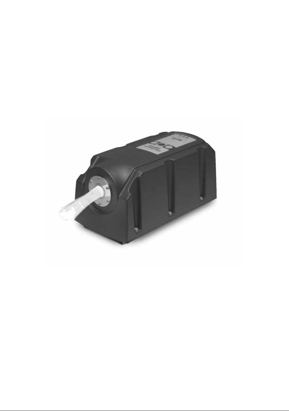
Thank you for selecting the Martin FiberSource CMY150. The FiberSource
CMY150 is an automated 150-watt color-changing luminaire for illuminating fiber
optic cables in permanent installations. It has a weather-resistant IP rating of 44 that
enables it to be used in outdoor installations. It features seamless CMY color
mixing and full-range continuous dimming. The fixture may be operated with DMX
controllers, in synchronization with other units (with or without a controller), and in
stand-alone mode with programmable start and stop times, and/or light level
activation/deactivation.
UNPACKING
The FiberSource CMY150 comes with a user manual and a Philips MasterColor
CDM-SA/R 150W lamp (installed).
SAFETY INFORMATION
Warning! This product is not for household use.
This product presents risks of lethal or severe injury due to fire and heat, electric
shock, ultraviolet radiation, lamp explosion, and falls. Read this manual before
powering or installing the fixture, follow the safety precautions listed below and
observe all warnings in this manual and on the fixture. If you have questions about
how to operate the fixture safely, please contact your Martin dealer or call the
Martin 24-hour service hotline at +45 70 200 201.
Guarding against electric shock
• Disconnect the fixture from AC power before removing or installing the lamp,
fuses, or any part.
• Always ground (earth) the fixture electrically.
• Use only a source of AC power that complies with local building and electrical
codes and has both overload and ground-fault protection.
• Refer all service to a Martin service technician.

Introduction
5
Preventing UV radiation and lamp explosion
• Never operate the fixture with missing or damaged lenses, without a fiber adaptor
installed, or with the housing removed.
• When replacing the lamp, allow the fixture to cool for at least 15 minutes before
opening the fixture.
• Do not stare directly into the light. Never look at an exposed lamp while it is lit.
• Replace the lamp if it becomes defective or worn out.
Guarding against burns and fire
• Never attempt to bypass the thermostatic switch or fuses. Always replace defective
fuses with ones of the specified type and rating.
• Keep at least 0.2 meter (8 in) clear around the air vent.
• Keep all combustible materials (for example fabric, wood, paper) at least 0.1 meter
(4 inches) away from the fixture. Keep flammable materials well away from the
fixture.
• Install the fixture in a well ventilated area.
• Never place filters or other materials over the lens.
• The exterior of the fixture becomes very hot, up to 70° C (158° F) during normal
operation. Do not locate the fixture in areas where accidental contact is likely.
• Do not modify the fixture or install other than genuine Martin parts.
• Do not operate the fixture if the ambient temperature (Ta) exceeds 40° C (104° F).
Preventing injury due to falls
• When suspending the fixture above ground level, verify that the structure can safely
hold the weight of all installed devices.
• Block access below the work area whenever installing or removing the fixture.

6
Installation
I
NSTALLATION
2
This section describes in general terms how to mount the fixture and connect it to
data and AC power. The procedures in this chapter shall be performed by qualified
professionals:
1“AC power”
2 “Fiber optic cable” on page 9
3 “Fixture orientation and location” on page 11
4 “Data link” on page 12
AC POWER
Do not connect the FiberSource CMY150 to an electrical dimmer system: doing so
can damage the electronics.
Warning! Disconnect the fixture from AC power before removing any
cover.
Important! Verify voltage and frequency settings before applying power.
POWER SUPPLY SETTINGS
The FiberSource CMY150 is factory-wired to one of the configurations shown in
Table 1. The model number and factory settings are printed on the serial number
label which can be found on the base of the fixture. If your local AC voltage or
frequency differ from the settings for your model, the fixture’s power supply must
be rewired by a qualified installer or technician.
Model No. Voltage Frequency
90523000 230 V 50 Hz
90523100 120 V 60 Hz
Table 1: Default Power Supply Settings
Installation
7
Rewiring the power supply
Always use the setting that most closely matches the local AC mains voltage and
frequency.
1 Verify that the FiberSource CMY150 is isolated from AC power.
2 Remove the fixture housing using a 5mm Allen wrench.
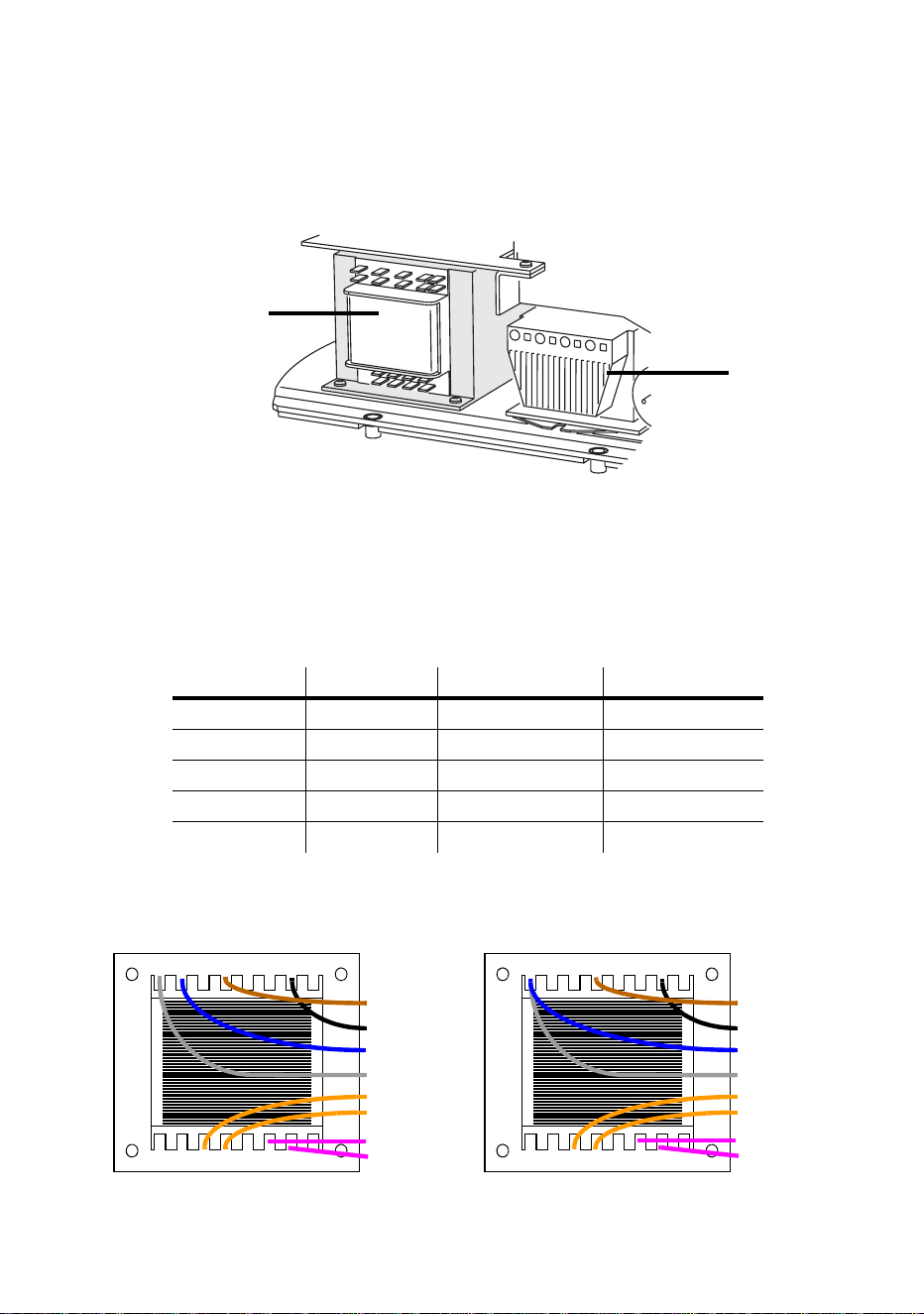
3 On the transformer, move the brown and blue wires (those with insulated spade
plugs) to the transformer taps shown for your mains voltage (see Table 2).
Important! Do not move the grey wire from terminal 9 or the black wire from
terminal 15.
Mains voltage Setting Brown wire on tap Blue wire on tap
95 - 109 V 100 V 12 10
110 - 130 V 120 V 12 9
200 - 219 V 210 V 15 10
219 - 239 V 230 V 15 9
240 - 260 V 250 V 16 9
Table 2: Transformer settings
Transformer
Ballast
10 11 12 13 14 15 169
23456781
orange (12 V)
orange (12 V)
grey
blue
black
brown
100 volts
10 11 12 13 14 15 169
23456781
orange (12 V)
orange (12 V)
grey
blue
black
brown
120 volts
purple (24 V)
purple (24 V)
purple (24 V)
purple (24 V)
8
Installation
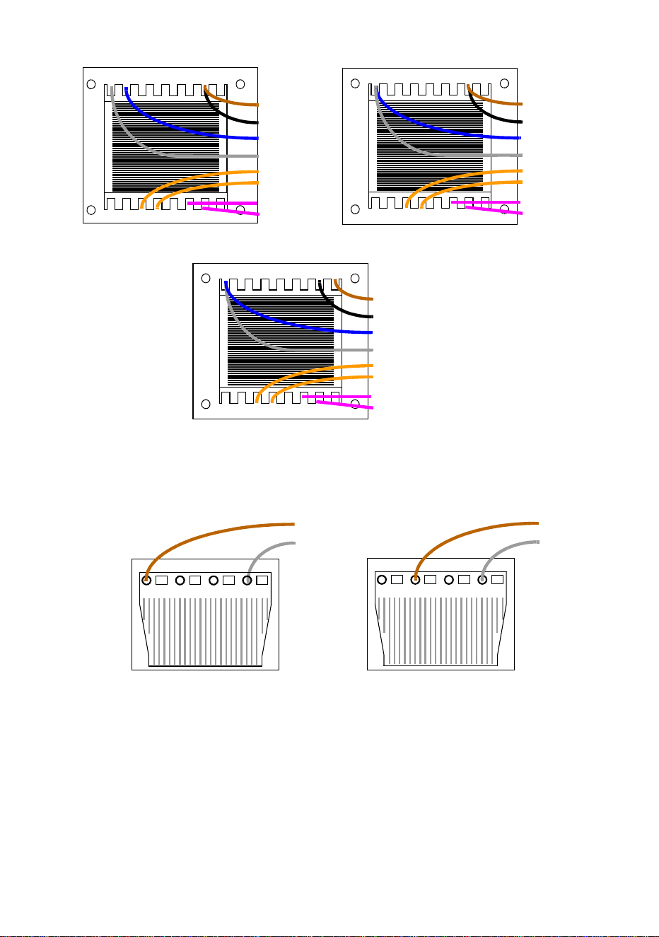
4 To set the frequency, move the brown wire on the ballast to the “230-50” (50 Hz) or
“230-60” (60 Hz) terminal as shown. The wire is released and locked by inserting a
small screwdriver in the square hole next to the terminal and prying back the spring.
5 Tug lightly on the brown wire to make sure that it is connected securely.
6 Replace the fixture housing before applying power.
MAINS CONNECTION
Warning! For protection from dangerous electric shock, the fixture must
be grounded (earthed). The AC mains supply shall be fitted with
a fuse or circuit breaker, ground-fault protection, and a means
to isolate the fixture from the mains during service or when not
in use.
10 11 12 13 14 15 169
23456781
orange (12 V)
orange (12 V)
grey
blue
black
brown
210 volts
10 11 12 13 14 15 169
23456781
orange (12 V)
orange (12 V)
grey
blue
black
brown
230 volts
purple (24 V)
purple (24 V)
purple (24 V)
purple (24 V)
10 11 12 13 14 15 169
23456781
orange (12 V)
orange (12 V)
grey
blue
black
brown
250 volts
purple (24 V)
purple (24 V)
grey
brown
50 Hz
60 Hz
grey
brown

Installation
9
The FiberSource CMY150 is equipped with a 1.8-meter (5.9 ft.) length of 3-
conductor 0.75 mm
2
(~18 AWG) electrical cable for connection to the AC power
supply. The cable attaches with 1/4” female spade plugs on the live and neutral
wires and a ring terminal on the ground wire. Other cable can be installed as
follows.
Replacing the mains lead
1 Isolate the fixture from AC power.
2 Remove the fixture housing.
3 Disconnect the existing mains cable and pull it through the hole in the chassis.
4 Pass the new cable through the hole in the chassis and connect the leads. The live
wire connects to PL3, the neutral wire connects to PL1, and the ground wire connects
to the chassis screw terminal.
5 Draw up the slack in the AC and data cables and replace the fixture housing.
Installing a cord cap on the mains lead
A cord cap may be installed on the mains lead for testing, service, and temporary
applications.
Following the cord cap manufacturer’s instructions, connect the yellow and green
wire to ground (earth), the brown wire to live, and the blue wire to neutral. Table 3
shows some pin identification schemes; consult an electrician if you have any
doubts about proper installation.
FIBER OPTIC CABLE
Fiber optic cable is connected to the FiberSource CMY150 using one of the
available fiber adaptor kits:
• P/N 91611035, for 75-350 x Ø1mm fibers. This has a diameter of 30mm and is
supplied with an adaptor ring that increases the adaptor diameter to 38mm so that it
will fit in the port of the FiberSource CMY150 fixture.
• P/N 91611034, for 350-800 x Ø1mm fibers. This has a diameter of 38mm.
Wire (EU) Wire (US) Pin Marking Screw (US)
brown black live “L” yellow or brass
blue white neutral “N” silver
yellow/green green ground green
Table 3: Cord Cap Connections

10
Installation
The fiber adaptors are tapered to fit a varying number of fiber optic cables. The
adaptor often needs to be cut for proper fit and maximum light output.
Cable types
The following guidelines provide a starting point for estimating your needs. Light
transmission through fiber-optic cable depends on its quality and results will vary
depending on the type of cable used.
SIDE-EMITTING CABLE
With 1 fixture, best results are had when the fiber optic cable is 10 m (33 ft.) or
shorter. The length may be increased to 15 m (50 ft.) by looping the cable and
illuminating both ends. With 2 fixtures, one at each end of the cable, lengths up to
30 m (100 ft.) can be achieved.
END-EMITTING CABLE
Light output decreases with length: keep the cable as short as possible. The
maximum recommended length is 25 meters. Cut the light emitting end of the fibers
with a sharp knife for maximum output.
Installing fiber optic cable
1 Install the cable in the adaptor ferrule according to the instructions supplied with the
adaptor ferrule.
2 Insert the adaptor ferrule into the port of the FiberSource CMY150.
Warning If your adaptor ferrule is the smaller 30 mm diameter adaptor
(P/N 91611035), then you need to insert it into an adaptor ring to
increase the diameter to 38 mm. Place the adaptor ring onto the
adaptor ferrule so that the ends are flush. Screw the adaptor
ring fast using a 2mm Allen wrench. Do not push the adaptor
ferrule past the end of the adaptor ring as the fiber will be too
close to the light source and will be damaged.
3 Tighten the set screw with a 2 mm (5/64 in.) Allen wrench.

Installation
11
FIXTURE ORIENTATION AND LOCATION
The FiberSource CMY150 can be installed in dry or damp locations.
Do not:
• Bury the FiberSource CMY150 or otherwise locate it in an unventilated space.
• Mount the FiberSource CMY150 on a wall in a vertical alignment. It may be
mounted horizontally (see “Fastening the FiberSource CMY150 to a structure” on
page 11).
• Install in wet locations.
Install the fixture in a location where it is:
• at least 0.5 meters (20 inches) away from the surface to be illuminated,
• at least 0.1 meter away from any combustible materials, and
• away from accidental public contact.
The fixture normally rests on the four plastic feet in its base.
Fastening the FiberSource CMY150 to a structure
To fasten the FiberSource CMY150 to a structure:
1 Remove the fixture housing using a 5mm Allen wrench.
2 Separate the base plate from the fixture chassis by removing the 4 Hex screws using
a 5mm Allen wrench.
3 Remove the four plastic feet from the base using a cutting or clipping tool.
4 Ensuring that both the mounting hardware and the supporting structure are able to
bear the weight of the fixture, bolt the base plate to the structure using hardware that
will fit through the four 13mm (0.5 in) holes. Note that if you are attaching the fixture to
a vertically-aligned structure such as a wall then the plate must be aligned
horizontally along its length (as in the following illustration).
Due to the restrictions of some lamps and the potential for water to enter the fixture
through the air filter, vertically-aligned mounting on a vertical surface such as a wall is
not recommended.
5 Re-attach the chassis to the base plate with the four Hex screws and a 5mm Allen
wrench.
6 Replace the fixture housing.
12
Installation
DATA LINK
A data link is required for DMX controller operation, and for synchronized stand-
alone operation of multiple FiberSource CMY150s.
Cable and junctions
The FiberSource CMY150 provides a dual 1.8 meter (5.9 ft.) 24 AWG cable with
locking 3-pin male and female XLR connectors for data connection. The male cable
is the data input and the female cable is the data output. The connectors are wired
pin 1 to shield (gnd.), pin 2 to signal - (cold), and pin 3 to signal + (hot).
Use RS-485 data cable designed for outdoor use to extend the link. RS-485 cable
has low capacitance and a characteristic impedance of 85 to 150 ohms. It is
electrically shielded and has at least 1 twisted-pair of conductors. The minimum
wire size is 0.2 mm
2
(24 AWG) for runs up to 300 meters (1000 ft.) and 0.322 mm
2
(26 AWG) for runs up 500 meters (1640 ft.).
When the fixture is installed outdoors, the XLR connectors
must be protected in a weatherproof housing. Alternatively,
data cables may be connected in weatherproof electrical
junction boxes, or the data cable can be replaced with
separate input and output cables that connect directly inside
the fixture. The leads connect to the main circuit board as
shown in the illustration to the right.
200
90
70
152
80
ground
hot (white)
cold
not used
PCB data
connections

Installation
13
Adaptors
Adaptors may be required to connect the FiberSource CMY150 to the controller or
other 5-pin devices. Adaptor cables for indoor use are available from Martin. The
adaptor cables are wired as shown below.
SPLITTER/AMPLIFIERS
A device such as the Martin 4-Channel Opto-Isolated RS-485 Splitter/Amplifier
may be used to branch the data link and/or extend its length. Do not use a “Y”
connector to split the link.
TERMINATORS
Termination of the data link is required for trouble-free communication. For
temporary installations, this can be achieved with a male termination plug inserted
into the data output cable of the last fixture in each chain. A termination plug is
simply an XLR connector with a 120 ohm resistor soldered across pins 2 and 3.
For permanent terminations, the link can be terminated with a 120 ohm resistor
across the hot and cold data terminals at the main circuit board inside the last fixture
in each chain.
Building a data link
To build a data link:
1 Connect a data cable to the controller’s data output. A male 5-pin to female 3-pin
adaptor may be required. Lead the data cable from the controller to the first fixture
and plug it into the male data cable.
2 Connect the output of the fixture closest to the controller to the input of the next
fixture. Continue in this manner. Up to 32 fixtures may be connected output to input.
3 Terminate the link, as described previously, at the output of the last fixture in the
chain.
Adaptor
Male Female
1
2
3
4
5
1
2
3
5-pin to 3-pin
P/N 11820005
Adaptor
Male Female
1
2
3
1
2
3
4
5
3-pin to 5-pin
P/N 11820004

14
Settings
S
ETTINGS
3
This section describes how to set the control address, personalities, and clock. To
set user options you need a Martin MP-2 Uploader that has been loaded with the
FiberSource CMY150’s control software and connected to the fixture or data link.
Please refer to the MP-2 Uploader user manual for details.
Note: Fixtures do not provide feedback to the uploader. Therefore, the current
settings can only be read by observing the behavior of the fixture.
MODES
The uploader provides two ways to access fixtures: single-fixture mode and all-
fixtures mode. In single-fixture mode, the uploader communicates only with the
fixture at a designated address. In all-fixtures mode, the uploader communicates
with all fixtures, of the same type, to which it is connected.
Fixture-specific settings such as the control address should be made in single-
fixture mode. If no other fixtures are connected, however, then all-fixtures mode
may be used. Global settings are made easiest in all-fixtures mode.
CONTROL ADDRESS
The control address, also known as the start channel, is the first channel used to
receive instructions from the controller. Each fixture needs its own control address
set, and uses this address and subsequent control channels to receive instructions
from a controller.
The FiberSource CMY150 uses seven channels of control data. It reads the data on
the start channel and the next six channels. If the control address is set to 100, the
fixture uses channels 100, 101, 102, 103, 104, 105, and 106. Channel 107 would be
the control address for the next fixture. The factory set control address is 1.
If two or more fixtures are set up with the same address, they will receive the same
instructions and should behave identically. Setting up identical fixtures with the
same address is a good tool for troubleshooting unexpected behavior and an easy
way to achieve synchronized action.

Settings
15
Important! When setting the address, either use single-fixture mode or
isolate all other fixtures from the uploader.
To set the control address:
1 Prepare an upload device as described in the uploader user manual. If you know the
address to which the fixture is currently set, that is, the address to change from,
connect the uploader to the data link and use single-fixture mode. Otherwise, use all -
fixtures mode and isolate all other fixtures from the uploader. Apply power to the
fixture.
2 If using single-fixture mode, scroll to the fixture’s current (from) address and press
OK.
3 Select
DMX address from the fixture menu.
4 Scroll to the desired control address and press OK.
5 Press OK again to confirm and save the setting.
PERSONALITY SETTINGS
The following settings are available to modify fixture behavior.
DMX Lamp-off: When the DMX Lamp-off personality is on (the default setting),
lamp power can be turned off from the controller by setting channel 1 to a decimal
value from 248 to 255. When set to off, the lamp-off command executes only if
channels 3, 4, and 5 are set to values from 230 to 232.
DMX reset: When the DMX Reset personality is on (the default setting), the
fixture can be reset from the controller by setting channel 1 to a decimal value from
208 to 217. When set to off, the reset command executes only if channels 3, 4, and 5
are set to values from 230 to 232.
Automatic Lamp-on: When the Automatic Lamp-on personality is on, the fixture
turns on the lamp within 90 seconds of power on. When set to off (the default
setting), a lamp-on command is required to turn on the lamp.
To set a personality setting:
1 Prepare and connect an upload device as described in the uploader user manual.
Apply power to the fixture.
2 Select single fixture mode to change a setting on a single fixture, or all-fixtures mode
to make global changes.
3 If using single-fixture mode, enter the fixture’s address.
4 Select
Special from the fixture menu.
5 Select the desired personality and setting. (See “MP-2 control menu” on page 37.)
Press OK.

16
Settings
CLOCK
The FiberSource CMY150 has a battery operated 24-hour clock that can start and
stop stand-alone operation.
To set the clock:
1 Prepare and connect an upload device as described in the MP2 Uploader manual.
Apply power to the fixture.
2 Select all-fixtures mode.
3 Select
Time from the fixture menu.
4 Select
Hour and scroll to the current hour.
5 Press OK.
6 Select
Minute and scroll to the current minute.
7 Press OK.
8 Press Back to return to the main menu.
General operation
17
G
ENERAL
OPERATION
4
GENERAL GUIDELINES
For optimum lamp life, turn off the lamp whenever illumination is not required for
extended periods of an hour or more. However it is a good idea to keep the fixture
power on so that the fans continually operate, regardless of whether or not the lamp
is lit. This keeps air circulating internally and prevents condensation from building
up inside the fixture.
When the temperature is expected to fall below freezing, leave the fixture powered
on when not in use to keep the electronics warm. The lamp, however, may be
switched off.
Always allow the lamp to warm up fully before turning it off.
Avoid turning on several lamps at once.
THE LEDS AND FIXTURE OPERATING
STATUS
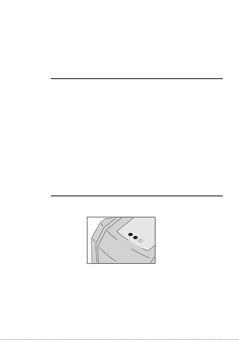
Two LEDs on the rear panel display the fixture status. Normal operation is indicated
by two green LEDs. See Table 4 for other status messages.
The LEDs flash off for a brief instant at regular intervals to prevent false readings
when the light sensor samples the light level.
Data
Power
Senso
r

18
General operation
When the fixture is powered up:
1 A check is performed on the software - both LEDs will blink yellow.
2 If the test is:
• Successful, both LEDs will blink green.
• Unsuccessful, the LEDs will blink yellow and red. In this case perform a DMX
upload and restart the fixture.
3 The installed firmware version number is then displayed. The number of red flashes
in the Power LED indicates the digit to the left of the decimal point and the number
of green flashes in the Data LED indicates the digit to the right of the decimal point.
For example, if the firmware version is 1.3, The Power LED flashes red once and
the Data LED flashes green three times.
4 The fixture will reset - both LEDs will blink yellow.
Appearance
MessagePower LED Data LED
Steady green - Effects OK.
- Steady green Data OK.
- Steady red Invalid data/no data.
Steady yellow Steady yellow Upload in progress.
Flash red - Memory error (or - during start up - the
number of flashes indicates the number
to the left of the decimal point in the
software version number).
- Flash green During start up - the number of flashes
indicates the number to the right of the
decimal point in the software version
number).
Flash yellow Flash yellow Test/reset in progress.
- Off No data detected.
Flash yellow and red Flash yellow and red Application error (perform DMX upload.
See “Firmware updates” on page 32).
Table 4: LED status messages

Stand-alone operation
19
S
TAND
-
ALONE
OPERATION
5
This chapter describes how to operate the FiberSource CMY150 in stand-alone
mode where the fixture executes color changes at set intervals and speeds, at pre-
defined periods during the day, or when the light level falls below a defined level.
The term stand-alone is used to mean that the FiberSource CMY150 is not
connected to a controller, but is programmed with a series of up to 20 scenes that
play continuously in a loop. The term ‘stand-alone operation’ can be applied to a
single fixture, or to multiple fixtures operating synchronously.
Up to 32 FiberSource CMY150s and Exterior 200s may be connected for
synchronized operation triggered by a “master” fixture. Synchronous operation of
multiple fixtures requires that they be connected on a data link.
Execution of a stand-alone program may be set to start automatically upon power-
on, or toggled on/off with an MC-X controller, which also provides direct selection
of seven scenes.
When programming for stand-alone operation, you might find the summary of
commands available in “MP-2 control menu” on page 37 useful as a quick
reference.
PROGRAMMING FIXTURES
The programming of scenes, and setting up of master/client relatio
nships, is
performed using an MP-2 Uploader. The uploader is connected to the fixture, used
to program the stand-alone settings for that fixture (or all the fixtures connected to
that fixture by data link), and then removed. Once a fixture is subsequently switched
on it can automatically run the scenes in its program in a loop, according to the
triggering criteria you have specified (time of day, or light level).
To summarize, you can use the MP-2 Uploader to program:
• Individual fixtures, one at a time.
• The same program in multiple fixtures that are linked with data cables.
• Individual programs in multiple fixtures that are linked with data cables.
If you are not familiar with the use of the MP-2, then it is recommend that you
familiarize yourself with it using the MP-2 Uploader manual.

20
Stand-alone operation
Getting started
1 Plug the fixture’s, or data link’s, data-input cable (male) into the 3-pin “DMX/RS-485
OUT” socket on the MP-2.
2 Apply power to the fixture and the MP-2.
3 Select
Read Memory Card from the MP-2 menu.
4 Select the most recent FiberSource CMY150 software from the list. (Note that these
files are numbered according to the firmware level. The firmware version that is
installed in the FiberSource CMY150 is displayed by its LEDs on power up. The
number of red flashes in the Power LED indicates the digit to the left of the decimal
point and the number of green flashes in the Data LED indicates the digit to the right
of the decimal point. For example, if the firmware version is 1.3, the Power 1 flashes
red once and Data LED flashes green three times.)
5 Select
Fixture menu. It is from this point you use the keys on the uploader
to navigate and select the desired menu item. For further guidance see the following
sections.
Selecting fixtures to program
Before selecting any fixture to program you must have set its control address. If you
have not yet done so, follow the instructions described in “Control address” on page
14.
You have the option of programing all the FiberSource CMY150s on a data link, or
an individual FiberSource CMY150. Fixture-specific settings such as the control
address should be made in single-fixture mode. If no other fixtures are connected,
however, then all-fixtures mode may be used. Global settings are made easiest in
all-fixtures mode. For example, it might be appropriate to program the time, or
trigger criteria into all fixtures simultaneously, while program scenes might be
programmed into fixtures individually.
Note that it is important that all the fixtures have the same software level set, or the
results will be unpredictable. For more information see, “Firmware updates” on
page 32.
SELECTING A SINGLE FIXTURE
To program a single fixture:
1 Select Single address from the Fixture menu.
2 Select a start address that corresponds to the fixture that you want to program using
the arrows.
3 Select
OK.

Stand-alone operation
21
SELECTING ALL FIXTURES ON A DATA LINK
To program all fixtures on the data link simultaneously, select All
addresses
from the Fixture menu.
Enabling or disabling stand-alone mode
To:
• Disable stand-alone mode, select Stand alone, then Enable SA,
and then
Off.
• Enable stand-alone mode, select Stand alone, then Enable SA, and
then
On.
Stand-alone mode can be disabled temporarily by:
• Turning the fixture off.
• Connecting a controller and sending control signals.
Stand-alone operation resumes, when the fixture has been turned off and then
turned back on again, provided that the
Auto prog. on option has been
specified for the fixture (for more information see “Automatic program start at
power-on” on page 25), or when another trigger event occurs (light-level or time
trigger).
Setting master/client options for synchronized stand-
alone operation
Synchronous stan
d-alone operation of up to 32 FiberSource CMY150s and Exterior
200s may be achieved by linking them together and using the synchronized stand-
alone operation function in which one unit - only - transmits synchronization signals
to the others. Note that only FiberSource CMY150 and Exterior 200 fixtures are
supported for synchronized stand-alone operation.
The master fixture triggers simultaneous program start and scene changes in the
other client fixtures. Each fixture stores its own program, and the master triggers
simultaneous program start and scene changes, in a cycle, based on its own
program.
Each fixture will run its own program repeatedly, changing scene when prompted to
by the master fixture, or until the master fixture finishes its own program and
signals that all fixtures should start from the first scene once again.
If you are running multiple fixtures simultaneously over a data link, then you must
set the master/client options for each fixture on the data link.

22
Stand-alone operation
DEFINING A MASTER FIXTURE
No more than one fixture may be the master. Any fixture on the link, however,
regardless of its position, may be the master.
1 From the Stand alone menu, select Mas
ter/client.
2 Select Master. This designates the fixture as the master fixture and causes it to
transmit synchronization signals to the client fixtures when its program runs.
DEF INING CLIENT F IXTURES
All other fixtures must be set as client fixtures:
1 From the Stand alone menu, select Master/client.
2 Select Client. This designates the fixture as a client fixture which will respond to
synchronization signals received from the master fixture.
Automatically triggering stand-alone operation
Stand-alone operation can be set for one or two periods during a 24 hour period,
and/or for a light level.
SETTING A LIGHT-LEVEL TRIGGER
Stand-alone operation can be set for a light level using the built-in light sensor. If
the light levels fall below the specified level then operation starts.
If both the timer and the light-level trigger are used, operation starts whenever it is
darker than the light-level setting, or within the times set.
To avoid false triggering by sudden light changes, for example from automobile
headlights, the light level must remain above or below the trigger threshold for 5
minutes.
To set the light trigger:
1 From the Stand alone menu, select Light level, then Enable, and then
On.
2 Select
Level and use the arrow keys to select a trigger level from 0 (darkest) to
255 (brightest). The light toggles on and off as you scroll past the current light level.
3 Select
OK.
Alternatively, you could capture the current light level using the sensor in the
fixture, and use this as the trigger level:
1 From the Stand alone menu, select Light level, then Enable, and then
On.
2 Select
Capture and then select Go.

Stand-alone operation
23
SETTING A TIMER TRIGGER
Stand-alone operation can be set for one, or two, periods, during a 24 hour period,
using the built-in clock.
If both the clock and the light sensor are used, operation starts, within the times set,
or whenever it is darker than the light-level setting. Operation stops at the stop time
provided that the ambient light is brighter than the light-trigger setting.
The first thing to do is to set the correct time. See “Clock” on page 16.
You can set timer operation for a single period, or for two periods, for example, one
period in the morning, and one period in the evening. To set the timer for a single
period:
1 Select Stand alone from the Fixture menu.
2 Select Timer, Timer, then Timer1.
3 Back out to
Stand alone.
4 Select Timer, then Timer1
5 Select Start, then Hour. Use the arrow keys to specify the start hour. Select
OK.
6 Select
Minute. Use the arrow keys to specify the start minute. Select OK.
7 Select
Back.
8 Select Stop, then Hour. Use the arrow keys to specify the stop hour. Select
OK.
9 Select
Stop, then Minute. Use the arrow keys to specify the stop minute.
Select
OK.
Programming effects in scenes
Stand-alone effects can be programmed and stored as scenes. Up to 20 scenes can
be programmed in each fixture. Each scene can contain individual color
characteristics, light intensity, a fade time, and a wait time.

24
Stand-alone operation
Each scene has a dynamic part -
the fade - during which effects
move to the scene’s programmed
positions, and a static part - the
wait - where the effects in the
scene are expressed.
The duration of the fade and wait
is programmed individually for
each scene. The fade time may be
0 - 120 seconds; the wait time
may be 0 - 600 seconds. The total
time it takes a scene to execute is
the sum of the fade and wait
times.
Programming is performed using the stand alone Program menu options to program
effects, such as:
When operating multiple fixtures in master/client mode, the wait time in
client fix
tures is disregarded, and is determined by the master fixture. Each fixture
fades at its own rate and then waits for the master to signal a scene, or program,
start before continuing.
When programming a master fixture, keep in mind that its total scene times should
be equal to or longer than the fade times of the other fixtures. You will get
unpredictable results if, for example, a scene is programmed in the master to last 10
seconds and in other fixtures to fade for 15 seconds.
Dimmer
The dimmer level.
Cyan
Magenta
Yellow
The color.
Random
colors
A continuously changing and random mix of all three, or any
two of the primary subtractive colors (CMY). The speed of
the effect can be set to slow, medium, or fast.
Fade
time
The fade time, anything from 0 to 120 seconds, is the time
it takes to change from one color to another. If the fade time
and wait time are both 0, the colors change continuously.
Wait
time
This is the duration a color is applied. A wait time can be
from 1 second to 600 seconds.
Fade
Fade
S
c
e
n
e
1
S
c
e
n
e
1
S
c
e
n
e
3
S
c
e
n
e
3
S
c
e
n
e
2
S
c
e
n
e
2
Wait
Wait
Wait
Fade

Stand-alone operation
25
SCENE MANAGEMENT
Once you have specified a mix of effects, you can store the scene using the options
available under the Program menu:
• Fewer scenes than the master fixture, it will run these in a cycle continuously, until the
master fixture signals that the program should start from the beginning again.
• More scenes than the master fixture, then the additional scenes will never run,
because the program will reset to the first scene when the master starts its program
from the beginning.
Automatic program start at power-on
You can specify that the program should start automatically when the fixture is
powered-on:
1 From the Stand alone menu select Auto prog. on.
2 Select
On.
Store
scene
Save settings in the current scene.
Add
scene
Save settings in a new scene at the end of the sequence.
Insert
scene
Save settings in a new scene before the current scene,
which moves up a number. Tip: Think of the Add and Insert
commands as Save commands, to be used as the last step
after programming all effects.
Delete
scene
Remove the current scene from memory. Scenes above the
deleted scene move down a number.
Next
scene
Step to the next scene.
Previous
scene
Step to the previous scene.
Clear
scenes
Remove all scenes from the fixture memory.
Run
program
The only in
dication of what the current scene is comes from the behavior of the
fixture.
When the program is run, scenes execute in a continuous, ascending loop.
If a cliented fixture has:
Run the scenes in the current program.

26
Stand-alone operation
Disconnecting the MP-2 Uploader
When all the settings have been made, disconnect the data input cable from the MP-
2.
Reconnect the output cable to the data link, or next fixture if applicable, and run
through the process described in this section.
EXECUTING STAND-ALONE SCENES
WITH AN MC-X CONTROLLER
Execution of the stand-alone program can be toggled on or off with an MC-X
controller, which can also be used to directly select and run of any one of the first
seven scenes in the program.
1 Connect the MC-X controller to the FiberSource CMY150’s data input. If multiple
FiberSource CMY150s are connected in a data link, plug the controller into the first
fixture in the link.
2To:
• Trigger scenes 00-06, press the numbered preset buttons on the MC-X.
• Have each fixture run its own routine, press [Auto].

Controller operation
27
C
ONTROLLER
OPERATION
6
The FiberSource CMY150 may be programmed and operated with any lighting
controller that is compatible with the USITT DMX standard. This section describes
how to operate the fixture with a controller. See the DMX protocol starting on page
36 for specific control values, and “Data link” on page 12 for connection
requirements.
LAMP CONTROL
Important Avoid striking several lamps at once!
The lamp can be turned on and off from the controller using the lamp-on and lamp-
off commands on channel 1. If the DMX Lamp-off personality is off, the lamp-off
command on channel 1 executes only if each of the CMY channels (3, 4, and 5) is
set to a DMX value from 230 to 232.
Strike lamps one at a time at 5 second intervals. Striking many lamps at once may
cause a voltage drop large enough to prevent lamps from striking, damage
electronics, and trip circuit breakers. To have the lamp strike automatically at
power-up, set the Automatic Lamp-on personality to on (see page 15).
Note: After being turned off, the lamp must cool for approximately 8 minutes
before it can be turned back on.
EFFECTS
The mechanical effects reset to their home positions when the fixture is powered on.
Effects can also be reset from the controller on channel 1. If the DMX Reset
personality is off, the reset command on channel 1 executes only if each of the
CMY channels is set to a DMX value from 230 to 232.
Dimmer
The mechanical dimmer provides smooth, high resolution, full-range dimming on
channel 2.

28
Controller operation
CMY subtractive color mixing
The CMY color mixing system is based on cyan, magenta, and yellow color filters.
A continuous range of colors may be achieved by varying the amount of each filter
from 0 to 100% on channels 3, 4, and 5. To execute specific color values, channel 6,
random color mixing, must be set to 0%.
Note that mixing 3 colors results in a loss of light - the light is blacked out when all
3 colors are fully applied. For maximum brightness, mix only 2 colors at a time.
Random color mixing
Random color mixing at slow, medium, and fast speeds is available on channel 6.
The colors can be mixed from any two, or all three, of the primary subtractive
colors. Choosing a random mixing of just two of the primary subtractive colors will
result in the following types of tones:
These random commands take precedence over values set on the cyan, magenta,
and yellow channels.
Effect speed
The speed at which effects fade, that is, move from one position to another, can be
controlled in two ways known as tracking control and vector control. You may
switch between tracking and vector control, but you cannot use both at the same
time.
Tracking control is enabled by setting channel 7, the speed channel, to a decimal
value from 0 to 2. Fades are then programmed using the controller’s cross-faders.
The FiberSource CMY150 has a digital filter algorithm that averages several
updates to ensure smooth movement.
Vector control provides a way to program fades on controllers without cross-faders
and may provide smoother fades than tracking control with some controllers,
particularly on very slow fades. A vector speed is programmed by setting channel 7
to a decimal value from 3 (fastest) to 245 (slowest). The speed setting applies to
dimmer and color fades. When using vector control, the controller cross-fade time,
if available, must be 0.
Combination Result
Cyan & magenta Bluish tones
Cyan & yellow Greenish tones
Magenta & yellow Reddish tones

Service
29
S
ERVICE
7
This section describes service procedures that can be performed by the user. Refer
all service not described here to a qualified Martin technician.
Warning! Disconnect the fixture from power before removing the fixture
housing.
LAMP REPLACEMENT
The FiberSource CMY150 uses one of the following discharge lamps.
Installing any other lamp may damage the fixture.
Warning! Allow the lamp to cool for 15 minutes before removing the lamp
cover.
Lamp replacement requires a 5 mm Allen wrench and a Philips screw driver.
To replace the lamp:
1 Disconnect the fixture from power and allow it to cool.
2 Remove the fixture housing.
Lamp Efficiency Color Temp. Average Life
Philips MasterColor CDM-SA/R
150W
33 Lm/W 4200 K 6000 hr.
Osram HQI-R 150W
(can only be operated horizontally)
35 Lm/W 4200 K 6000 hr.
Table 5: Lamp specifications
30
Service
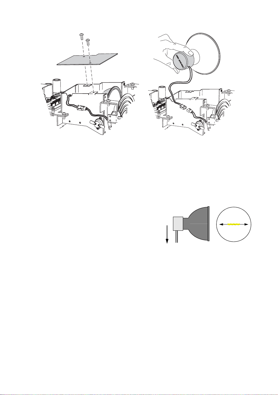
3 Remove the screws on the cover-plate over the lamp and then remove the cover-
plate.
4 Gently remove the lamp from its housing.
5 Remove the old lamp from the connecting plug.
6 Clean the glass bulb and reflector of the new lamp with an alcohol wipe or a clean,
lint-free cloth wetted with alcohol.
7 Holding the new lamp by its base, insert it firmly and squarely into the lamp housing.
8 Gently re-insert the lamp, without winding the wires around the lamp.
If you are installing the Osram HQI-R
150W lamp, note that the lamp may not be
operated in any position other than
horizontal. When the lamp is installed in the
fixture turn it so that the wires will point
towards the ground when the fixture is
permanently installed. This positions the
filament in the ideal horizontal burning
position. If this is not done the lamp may
deteriorate at an accelerated rate.
9 Connect the wires on the new lamp to the connecting plug.
10 Replace the lamp cover-plate, re-insert and tighten the screws.
11 Replace the fixture housing.
Service
31
CLEANING
Wipe off loose dirt with a damp cloth. Clean the housing with a soft brush or sponge
and a mild, non-abrasive car washing detergent.
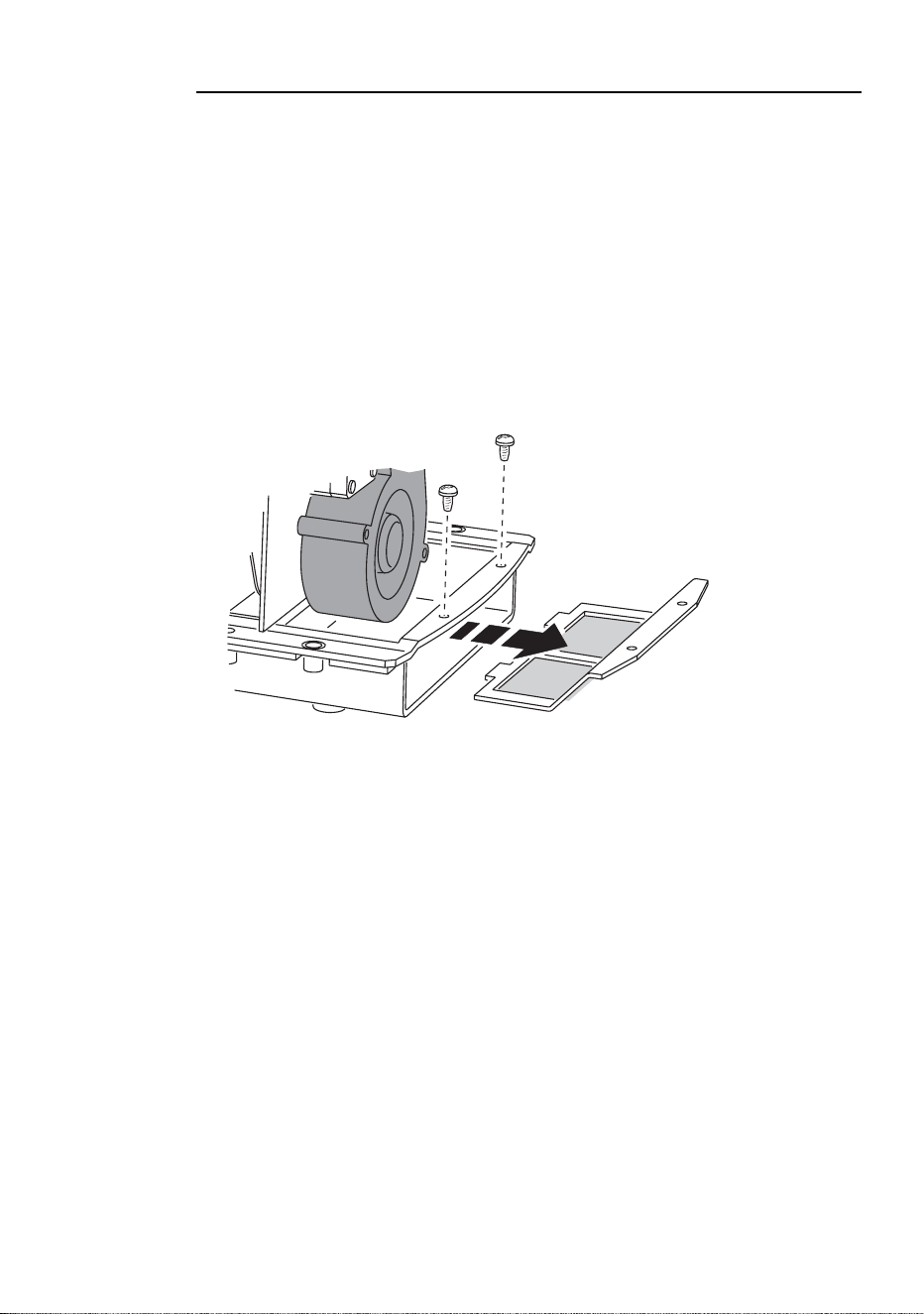
Cleaning the fan and air filter
To maintain adequate cooling, dust must be cleaned from the fan and air filter
periodically.
1 Disconnect the fixture from power.
2 Remove the fixture housing using a 2mm Allen wrench.
3 To remove the air filter, take off the fixture housing, and then remove the two screws
as shown in the following illustration.
4 Remove dust and dirt from the fan blades and air filter using a soft brush, cotton
swab, vacuum, or compressed air.
5 Replace the fixture housing.
The air filter is glued to its support, so washing it is not advised. We recommend the
installation of a new air filter (P/N 62400205) when the lamp is replaced.

32
Service
FIRMWARE UPDATES
Firmware updates are released when features are added. The latest version is
available from the Support Area of the Martin Professional web site at
http://www.martin.dk.
The installed firmware version number is displayed by the LEDs on power up (see
“The LEDs and fixture operating status” on page 17).
Firmware is installed using a Martin uploader or a 4064 DMX interface for the
Martin LightJockey controller. The procedure is found in the MP-2 user manual and
the Martin Software Uploader online help file.
REQUIREMENTS
The following are required in order to install software.
• The FiberSource CMY150 update file, available for download from the User
Support Area of the Martin web site (http://www.martin.dk).
• The Martin Software Uploader program, version 4.0 or later, available for download
from the Support Area of the Martin web site.
• A Martin MP-2 Uploader connected to a Windows 95/98/ME/2000 PC, or a
LightJockey Controller with a DMX Interface card.
Updating fixture firmware with the MP-2 Uploader
1 Connect a prepared MP-2 Uploader to the DMX link. Apply power to the fixtures and
the MP-2. Wait a few moments for the fixtures to reset.
2 Select
Read Memory Card from the MP-2 main menu.
3 Use the buttons on the right to scroll through the card slots. Select the slot that holds
the desired version of
EXT200 firmware.
4 Select
Update Software. Select Yes to confirm.
5 Select
Update in DMX mode to start the upload. The MP-2 initializes all
connected FiberSource CMY150s, which respond with two yellow LEDs in the status
display. Avoid interrupting the process: this will corrupt the software.
6 After a successful upload the fixtures reset with the new software. If an error occurs
and the fixtures do not reset, data was interrupted or corrupted during transmission.
Perform a boot mode upload as described below.
BOOT SECTOR UPLOAD
If the normal upload procedure does not work, or if the software update notes call
for a boot sector update, see the following section, “Performing a boot sector
update”.

Service
33
Performing a boot sector update
1 Make sure the FiberSource CMY150 is isolated from AC power. Remove the fixture
housing.
2 Using the diagram on the inside of the fixture housing as a reference, locate the
jumper on the printed circuit board at position PL2. Move the jumper to the “BOOT”
position (across pins 1 and 2).
3 Perform a boot mode upload as described in the uploader manual.
4 When the upload is complete, disconnect the fixture from power and move the jumper
at PL2 back to the “LOCK” position (pins 2 and 3).
5 Replace the fixture housing.
FUSE REPLACEMENT
Warning! Never replace fuses with ones of a different rating!
The FiberSource CMY150 has 3 fuses. The main fuse is located on the small circuit
board and the secondary fuses for the low-voltage power supplies are located on the
main circuit board.
Fuse replacement requires a 5 mm Allen wrench.
To replace a fuse:
1 Make sure the FiberSource CMY150 is isolated from AC power.
2 Remove the fixture housing.
3 Locate the main fuse which can be found by following the power cable to the smaller
of the two printed circuit boards. This is located just to the side of the lamp housing.
The mains fuse is a T 3.15 amp, high I2t, 250 volt fuse. Replace the defective fuse
with one of the same size and rating.
4 Replace the fixture housing before applying power.

34
Troubleshooting
T
ROUBLESHOOTING
8
Problem Probable cause(s) Remedy
No response from fixture when
power is applied.
No power to fixture. Check power cables.
Primary fuse blown. Replace fuse.
Secondary fuse blown. Replace fuse.
Fixture resets but does not
respond correctly to controller
(DMX mode operation).
Controller not connected. Connect controller.
Incorrect addressing of the
fixtures.
Check address setting on
fixture and controller.
Bad data link connection.
Inspect cables and correct
poor connections and/or
broken cables.
Conflict between tracking and
vector control.
Eliminate scene cross-fade on
controller or set ch. 7 to 0%.
Data link not terminated.
Insert termination plug in
output of last fixture.
Defective fixture or 2 devices
transmitting on link.
Bypass fixtures one at a time
until normal operation is
regained: unplug both
connectors and connect them
directly together.
Colors cannot be mixed. Random color mixing is on. Turn off random color mixing.
Fixture does not reset
correctly.
Electronic or mechanical
failure.
Contact service technician.
No light, lamp cuts out
intermittently, or burns out too
quickly.
Lamp missing or blown.
Disconnect fixture and replace
lamp.
Fixture or lamp is too hot.
Allow fixture to cool. If problem
persists, contact service
technician.
Incorrect power supply setting. Check setting.
Poor or uneven light.
Adaptor installed incorrectly.
Refer to Fiber Adaptor
Installation Note.
Rough fiber ends.
File fiber ends smooth as
described in Fiber Adaptor
Installation Note.
Osram lamp filament oriented
incorrectly.
Turn lamp so wires point
toward the ground.
No light and the fan does not
run.
No power to the fixture. Check connections.
Blown fuse. Replace fuse.

Troubleshooting
35
Fan runs but there is no light.
Lamp too hot to strike.
Wait a few minutes. Lamp will
strike when cool.
Incorrect voltage setting.
Check and correct voltage
setting.
Burned out lamp. Install new lamp.
Fixture overheating.
Allow to cool.
Improve air flow.
Clean the fan.
Problem Probable cause(s) Remedy

36
DMX protocol
DMX
PROTOCOL
A
Start code = 0
DMX channel Value Percent Function
1
* If the command is
disabled, set channels
3, 4, and 5 (CMY) from
230 to 232.
0 - 207
208 - 217
218 - 227
228 - 237
238 - 247
248 - 255
0 - 81
82 - 85
85 - 89
89 - 93
93 - 97
97 - 100
Reset, Lamp On/Off
Reserved (no change)
Reset fixture*
Reserved (no change)
Lamp power on
Reserved (no change)
Lamp power off* Note: T ≥ 5 seconds
2
0 - 255 0 - 100
Dimmer
Closed Æ open
3
0 - 255 0 - 100
Cyan
White Æ Cyan
4
0 - 255 0 - 100
Magenta
White Æ Magenta
5
0 - 255 0 - 100
Yellow
White Æ Yellow
6
0 - 14
15 - 34
35 - 54
55 - 74
75 - 94
95 - 114
115 - 134
135 - 154
155 - 174
175 - 194
195 - 214
215 - 234
235 - 255
0 - 5
5-13
13-21
21-29
29-37
37-44
45-52
53-60
61-68
68-76
76-84
84-92
92-100
Random Color Mixing
Off
CMY, slow
CMY, medium
CMY, fast
MY, slow
MY, medium
MY mix, fast
CM, slow
CM, medium
CM, fast
CY, slow
CY, medium
CY, fast
7
0 - 2
3 - 245
246 - 251
252 - 255
0 - 1
1 - 96
96 - 98
99 - 100
Speed
Tracking
Fast Æ slow
Reserved (no change)
Fast
MP-2 control menu
37
MP-2
CONTROL
MENU
B
Level 1 Level 2 Level 3 Level 4 Level 5 Effect (default settings bold)
DMX
address
1-512 Select control address.
Stand-
alone
Enable SA
Off Disable stand-alone operation.
On Enable stand-alone operation.
Light level
Enable
Off Disable light level operation.
On Enable light level operation.
Level 1-255
Sets the light trigger level. 1 is darkest,
255 is brightest. When setting, light
switches on/off at current level.
Capture Go Capture current light level.
Timer
Timer
None Disable timer operation.
Timer 1 Use timer 1 to trigger start/stop.
Timer 2 Use timer 2 to trigger start/stop.
Both Timers Use timers 1 and 2 to trigger start/stop.
Timer 1
Start
Hour Set timer 1 start hour.
Minute Set timer 1 start minute.
Stop
Hour Set timer 1 stop hour.
Minute Set timer 1 stop minute.
Timer 2
Start
Hour Set timer 2 start hour.
Minute Set timer 2 start minute.
Stop
Hour Set timer 2 stop hour.
Minute Set timer 2 stop minute.
Auto Prog.
On
Off
Do not start the program at fixture power
on.
On Start program at fixture power on.
Master/
Client
No Master/Client
The fixture operates in isolation. This is
the default.
Master
Set the fixture to the master in a chain of
multiple fixtures.
Client
Set the fixture to be a client in a chain
of multiple fixtures.

38
MP-2 control menu
Stand-
alone
Program
Dimmer 0-255 Set dimmer level.
Cyan 0-255 Set cyan level.
Magenta 0-255 Set magenta level.
Yellow 0-255 Set yellow level.
Random
colors
Random off Disable random color.
CMY - slow Random colors, slow
CMY - medium Random colors, medium
CMY - fast Random colors, fast
Cyan/Mag - slow Random bluish colors, slow
Cyan/Mag - medi Random bluish colors, medium
Cyan/Mag - fast Random bluish colors, fast
Mag/Yel - slow Random reddish colors, slow
Mag/Yel - medi Random reddish colors, medium
Mag/Yel - fast Random reddish colors, fast
Cyan/Yel- slow Random greenish colors, slow
Cyan/Yel - medi Random greenish colors, medium
Cyan/Yel - fast Random greenish colors, fast
Fade time
Snap
Set scene fade time to zero, so that
scene changes are immediate.
1 sec - 2 min
Set scene fade time from one second up
to two minutes.
Wait (trig)
time
0 s- 10 m Set scene wait time up to 10 minutes.
Add scene Go Save new scene to end of sequence.
Next
scene
Go Call the next scene.
Previous
scene
Go Call the previous scene.
Store
scene
Go Save changes to current scene.
Insert
scene
Go Save new scene before current scene.
Delete
scene
Go Delete the current scene.
Clr all
scenes
No Cancel command.
Yes Delete all scenes.
Run
program
Leave Run the scenes in the program.
Time
Hour 0-23 Set the current hour in 24-hour time.
Minute 0-59 Set the current minute.
Level 1 Level 2 Level 3 Level 4 Level 5 Effect (default settings bold)

MP-2 control menu
39
Adjust
Reset On Reset effects to home position.
Lamp on On Turn on lamp.
Lamp off Off Turn off lamp.
All effects
Open Move all effects to open position.
Closed Move all effects to closed position.
Dimmer
Open Move dimmer to open position.
Closed Move dimmer to closed position.
Cyan
Open Move cyan flag to open position.
Closed Move cyan flag to full position.
Magenta
Open Move magenta flag to open position.
Closed Move magenta flag to full position.
Ye l lo w
Open Move magenta flag to open position.
Closed Move magenta flag to full position.
Special
DMX lamp
off
Off
Require confirmation of lamp-off.
(default)
On Enable lamp-off without confirmation.
DMX reset
Off Require confirmation of reset command
On
Enable reset without confirmation.
(default)
Auto lamp
on
Off Strike lamp from controller. (default)
On
Strike lamp automatically within 90
seconds of power on.
Version Leave
The installed firmware version number
is displayed by the LEDs on the top of
the fixture. The number of red flashes in
the Power LED indicates the digit to the
left of the decimal point and the number
of green flashes in the Data LED
indicates the digit to the right of the
decimal point. For example, if the
firmware version is 1.3, the Power LED
flashes red once and the Data LED
flashes green three times.
Level 1 Level 2 Level 3 Level 4 Level 5 Effect (default settings bold)

40
Specifications
S
PECIFICATIONS
C
PHYSICAL
Length: . . . . . . . . . . . . . . . . . . . . . . . . . . . . . . . . . . . . . . . . . . . . . . . . . . . . 398 mm (15.7 in)
Width:. . . . . . . . . . . . . . . . . . . . . . . . . . . . . . . . . . . . . . . . . . . . . . . . . . . . . . 195 mm (7.7 in)
Height: . . . . . . . . . . . . . . . . . . . . . . . . . . . . . . . . . . . . . . . . . . . . . . . . . . . . . 192 mm (7.6 in)
Weight: . . . . . . . . . . . . . . . . . . . . . . . . . . . . . . . . . . . . . . . . . . . . . . . . . . . . . . .8 kg (17.6 lbs)
SOURCE
Lamp: . . . . . . . . . . . . . . . . . . . . . . . . . . . . . . . . . . . . . . . . . . . . . . . . . . . . . .150 W discharge
Approved models: . . . . . Philips MasterColor CDM-SA/R 150W and Osram HQI-R 150W
Control:. . . . . . . . . . . . . . . . . . . . . . . . . . . . . . . . . . . . . . . . . . . . . . . . . . . Remote switchable
INSTALLATION
Minimum distance to combustible materials: . . . . . . . . . . . . . . . . . . . . . . . . . . . 0.1 m (4 in)
Mounting points: . . . . . . . . . . . . . . . . . . . . . . . . . . . . . . . . . . . . . . .5 x 13 mm (0.5 in) holes
Minimum clearance around fan and air vents: . . . . . . . . . . . . . . . . . . . . . . . . . . . 0.2 m (8 in)
Environment: . . . . . . . . . . . . . . . . . . . . . . . . . . . . . . . . . . . . . . . . . . . . Dry or damp location
Orientation:. . . . . . . . . . . . . . . . . . . . . . . . . . . . . . . . . . . . . . . . . . . . . . . . . . . . . . .Horizontal
CONSTRUCTION
Housing: . . . . . . . . . . . . . . . . . . . . . . . . . . . . . . . . . . . . . . . . . . Flame retardant ABS plastic
Color: . . . . . . . . . . . . . . . . . . . . . . . . . . . . . . . . . . . . . . . . . . . . . . . .RAL 7016, antrazit-gray
Ingress protection factor: . . . . . . . . . . . . . . . . . . . . . . . . . . . . . . . . . . . . . . . . . . . . . . . . IP 44
DESIGN STANDARDS
120V/60Hz “US” model: . . . . . . . . . . . . . . . . . . . . . . . UL 1598 / CSA C22.2 No. 250.0-00
230V/50 Hz “EU” model: . . . . . . . . . . . . . . . . . . . . . . . . . . . . EN 60598-1, EN 60598-2-17
THERMAL
Maximum ambient temperature (Ta):. . . . . . . . . . . . . . . . . . . . . . . . . . . . . . . 40° C (104° F)
Maximum surface temperature, steady state, Ta=40° C: . . . . . . . . . . . . . . . . 70° C (158° F)
Cooling: . . . . . . . . . . . . . . . . . . . . . . . . . . . . . . . . . . . . . . Filtered forced-air cooling system
AC SUPPLY
AC input: . . . . . . . . . . . . . . . . . . . . . . . . . . . . . . . . . . . . . . 1.8 m trailing cable w/o cord cap
Power supply options: . . . . . . . . . . . . . . . . . . . . . . . . . . . 100/120/210/230/250 V, 50/60 Hz
Primary fuse . . . . . . . . . . . . . . . . . . . . . . . . . . . . . . . . . . . . . . . . . . . .3.15 A, high I
2
t, 250 V

Specifications
41
MAXIMUM POWER AND CURRENT
100 V: . . . . . . . . . . . . . . . . . . . . . . . . . . . . . . . . . . . . . . . . . . . . . . . . . . . . . . . . 220 W, 2.4 A
120 V: . . . . . . . . . . . . . . . . . . . . . . . . . . . . . . . . . . . . . . . . . . . . . . . . . . . . . . . . . .220 W, 2 A
208 V: . . . . . . . . . . . . . . . . . . . . . . . . . . . . . . . . . . . . . . . . . . . . . . . . . . . . . . . . 200 W, 1.1 A
230 V: . . . . . . . . . . . . . . . . . . . . . . . . . . . . . . . . . . . . . . . . . . . . . . . . . . . . . . . . . .210 W, 1 A
250 V: . . . . . . . . . . . . . . . . . . . . . . . . . . . . . . . . . . . . . . . . . . . . . . . . . . . . . . . . . .220 W, 1 A
ELECTROMECHANICAL EFFECTS
Cyan filter:. . . . . . . . . . . . . . . . . . . . . . . . . . . . . . . . . . . . . . . . . . . . . . . . . . . . . . . . 0 - 100%
Magenta filter: . . . . . . . . . . . . . . . . . . . . . . . . . . . . . . . . . . . . . . . . . . . . . . . . . . . . . 0 - 100%
Yellow filter: . . . . . . . . . . . . . . . . . . . . . . . . . . . . . . . . . . . . . . . . . . . . . . . . . . . . . . 0 - 100%
Dimmer:. . . . . . . . . . . . . . . . . . . . . . . . . . . . . . . . . . . . . . . . . . . . . . . . . . . . . . . . . . 0 - 100%
CONTROL & PROGRAMMING
Control options: . . . . . . . . . . . .DMX-512, Martin remote control, stand-alone, master/client
Receiver: . . . . . . . . . . . . . . . . . . . . . . . . . . . . . . . . . . . . . . . . . . . . . . . . . . . . . . . . . . .RS-485
Setting and addressing: . . . . . . . . . . . . . . . . . . . . . . . . . . . . . . . . . . . . Remote with uploader
Firmware update:. . . . . . . . . . . . . . . . . . . . . . . . . . . . . . . . . . . . . . . . . . Serial upload (MUF)
Stand-alone trigger options: . . . . .Internal real-time clock with timer and light-level sensor
Stand-alone memory:. . . . . . . . . . . . . . . . . . . . . . . . . . . . . . . . . . . . . . . . . . . . . . . . 20 scenes
Data input: . . . . . . . . . . . . . . . . . . . . . . . . . . . . . . .1.8 m trailing cable with 3-pin XLR male
Data output: . . . . . . . . . . . . . . . . . . . . . . . . . . . . 1.8 m trailing cable with 3-pin XLR female
Data pinout: . . . . . . . . . . . . . . . . . . . . . . . . . . . . . . .Pin 1 shield, pin 2 cold (-), pin 3 hot (+)
DMX channels: . . . . . . . . . . . . . . . . . . . . . . . . . . . . . . . . . . . . . . . . . . . . . . . . . . . . . . . . . . .7
ORDERING INFORMATION
FiberSource CMY150, 230V, 50Hz: . . . . . . . . . . . . . . . . . . . . . . . . . . . . . . . P/N 90523000
FiberSource CMY150, 120V, 60Hz: . . . . . . . . . . . . . . . . . . . . . . . . . . . . . . . P/N 90523100
INCLUDED ITEMS
User manual: . . . . . . . . . . . . . . . . . . . . . . . . . . . . . . . . . . . . . . . . . . . . . . . . . . P/N 35000102
Philips MasterColor CDM-SA/R 150W:. . . . . . . . . . . . . . . . . . . . . . . . . . . . . P/N 97010113
ACCESSORIES
Fiber adaptor, 350-800 pcs. (50 pcs. interval) Ø1mm fiber, D=38mm: . . . . . P/N 91611034
Fiber adaptor, 75-350 pcs. (25 pcs. interval) Ø1mm fiber, D=30mm: . . . . . . P/N 91611035
MP-2 uploader: . . . . . . . . . . . . . . . . . . . . . . . . . . . . . . . . . . . . . . . . . . . . . . . . P/N 90758420
MC-X controller, 220 - 245 V / 50 Hz:. . . . . . . . . . . . . . . . . . . . . . . . . . . . . . P/N 90718200
MC-X controller, 110 - 120 V / 60 Hz:. . . . . . . . . . . . . . . . . . . . . . . . . . . . . . P/N 90718300
Philips MasterColor CDM-SA/R 150W:. . . . . . . . . . . . . . . . . . . . . . . . . . . . . P/N 97010113
Osram HQI-R 150W:. . . . . . . . . . . . . . . . . . . . . . . . . . . . . . . . . . . . . . . . . . . . P/N 97010101
Air filter. . . . . . . . . . . . . . . . . . . . . . . . . . . . . . . . . . . . . . . . . . . . . . . . . . . . . . P/N 62400205
