co
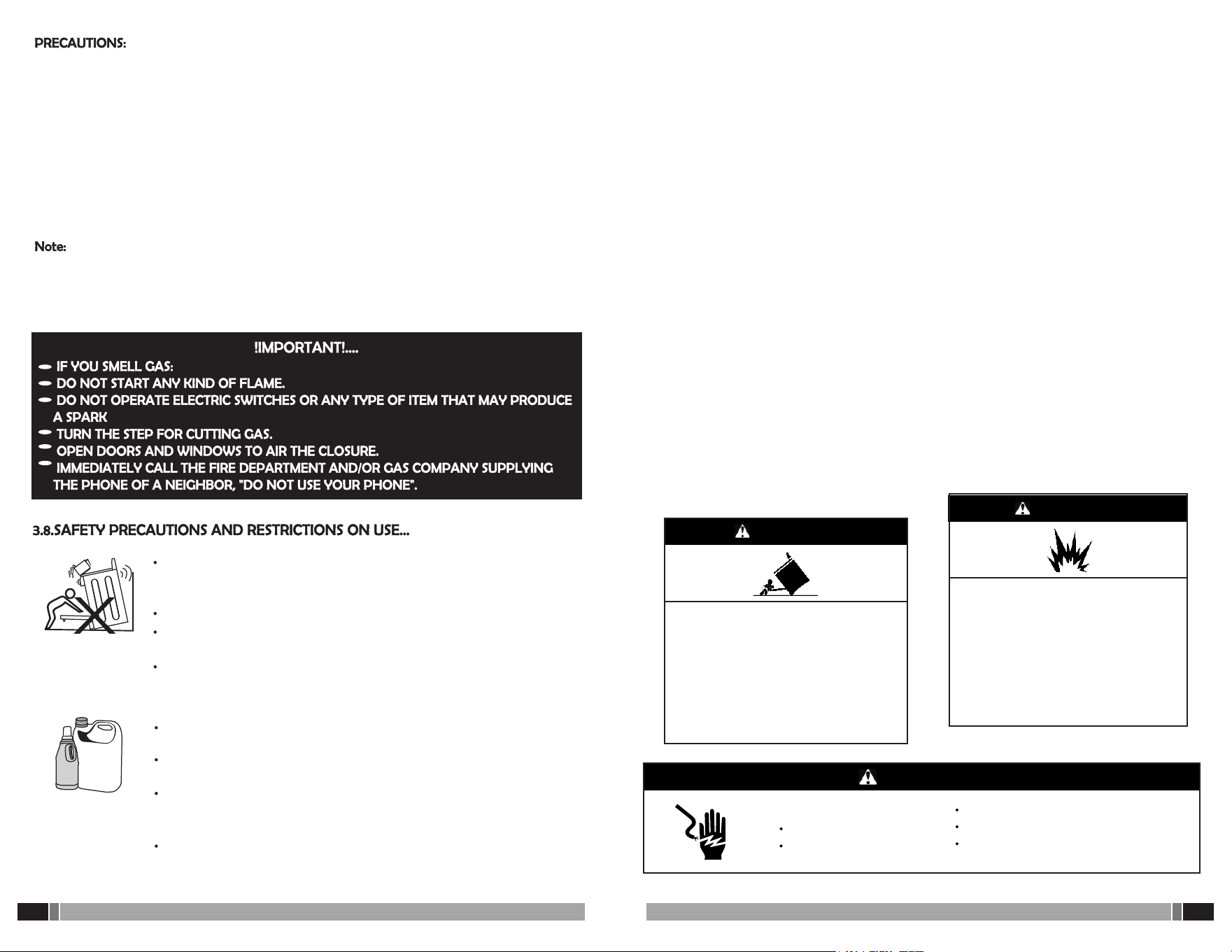
RECOMMENDATIONS FOR A PREVENTIVE APPROACH TO CO
Let the color of the
flame be blue
Do not clog vents.
Clean the burners
regularly
Have permanent
ventilation.
Contract maintenance
regularly
Check for the presence
of soot
CARBON MONOXIDE - CO is a gas of extreme danger that occurs when there is an
incomplete combustion of gas or any fuel, because of a lack of oxygen.
CARBON-CO MONOXIDE DOES NOT SMELL AND IS NOT SEEN. But it can be recognized
in the color of the domestic gas appliances
flame: If it is yellow or reddish there is danger. When there is soot (black coloration) in the
surroundings or in the pots where food is prepared there is danger.
Pay attention to the problem and follow the recommendations presented here
4 6
NO 1
4 6
1 2
1
AMOUNT
ACCESORIES
BACKGUARD.
DOUBLE GRADES
SIMPLE GRADES
BURNER CAP
ALUMINIUM BURNER BASE
GRADES OVEN
GRADES COMPARTMENT TRAY
REVIEWING CODE
NO
3 2
1 NO
5
5
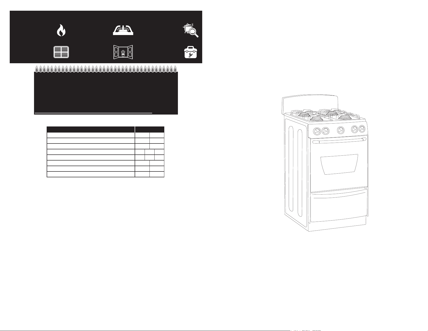
INSTRUCTIONS, INSTALLATION, USE AND MAINTENANCE MANUAL
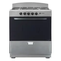
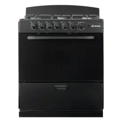
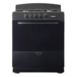
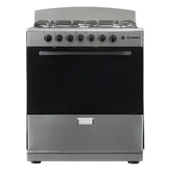
ELEMENT GAS RANGE
EEGR20A4MCCW
EEGR24A4MCCW
EEGR3A6MCCW
EEGR3A4MCCW
EEGR20A4MCCB
EEGR24A4MCCB
EEGR3A6MCCB
EEGR3A4MCCB
EEGR20A4MCCS
EEGR24A4MCCS
EEGR3A6MCCS
EEGR3A4MCCS
Element, the Element Logo, and Bring it home are trademarks of Element Brand
Holding, LLC. All other trademarks are the property of their respective owner, who has
not sponsored, endorsed, or approved this product. ©2025 Element Appliance
Company, LLC. All rights reserved.
Distributed by Element Appliance Company, LLC
Augusta, GA 30909
For service, support and warranty information:
Call 888.842.3577, email us at [email protected] or visit
www.elementelectronics.com
23
/
24
2
/
24
Pag. 18
Pag. 19
Pag. 20
Pag. 23
Pag. 21
2 TECHNICAL INSTRUCTION PARTS
AND MAINTENANCE, INSTALLATION INTENDED.
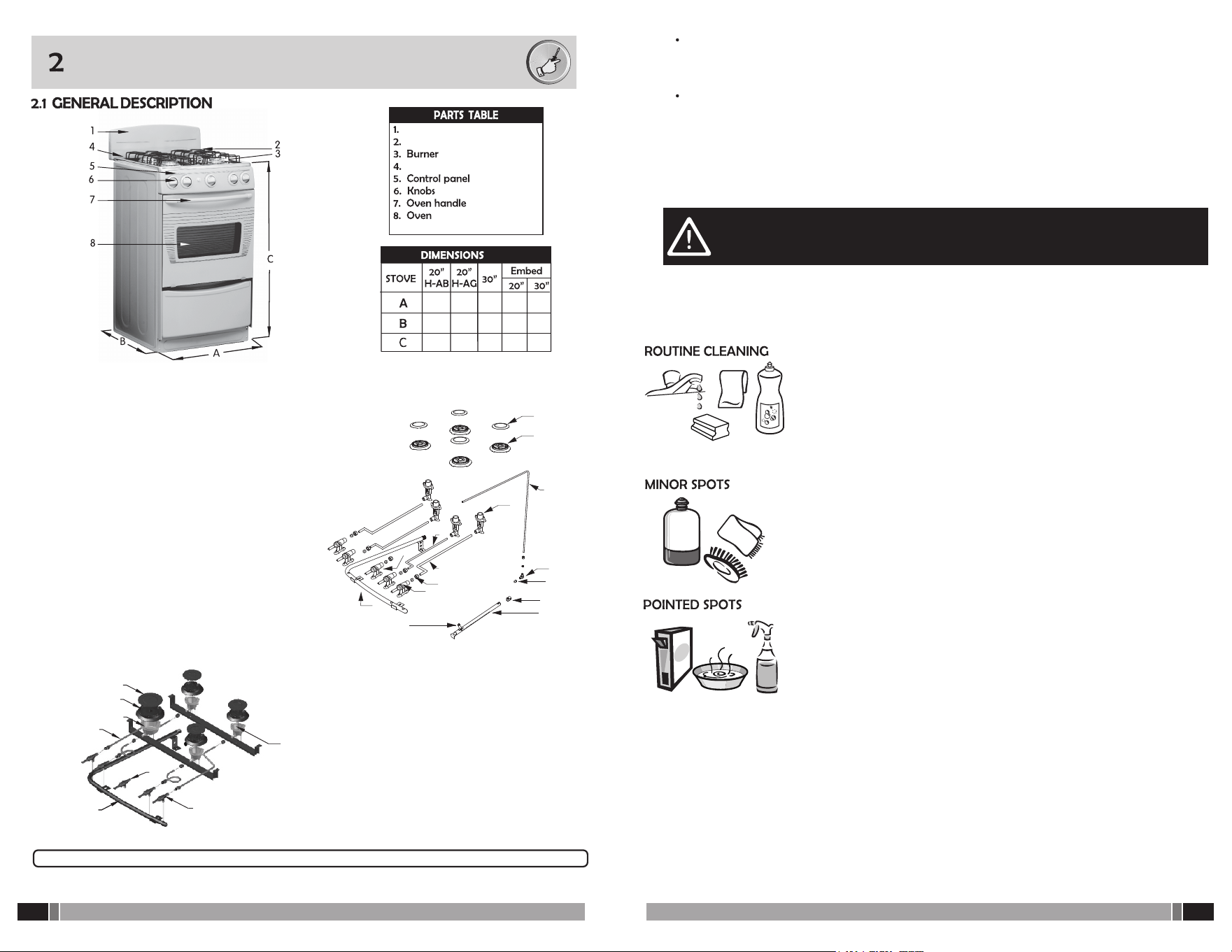
2.1 GENERAL DESCRIPTION
2.1.1 MAIN FEATURES
2.2 WARNING
2.3 CONSIDERATION
2.3.1. LOCATION
A. CLASS 1 GAS APPLIANCES ANCHOR
B. BACKGUARD INSTALLATION
2.3.2. GRADUATION OF SURFACE BURNERS FLAME.
1 LABELING INFORMATION
1.1 NAMEPLATE
1.2 RANGE SAFETY
3. OPERATING AND MAINTENANCE INSTRUCTIONS INTENDED
TO THE USER
3.1 BURNERIGNITION
3.1.1. STOVES WITH MANUAL IGNITION
3.1.2. STOVES WITH ELECTRONICIGNITION
3.2 ELECTRICAL CHARACTERISTICS.
3.2.1. GENERAL RECOMMENDATIONS FOR USE OF YOUR OVEN
3.2.2. ELECTRIC OVENS WITH LIGTH
3.2.3. CLEANING AND MAINTENANCE
3.3 STOVES WITH ELECTRIC GRILL
3.4 TEMPERED GLASS LID
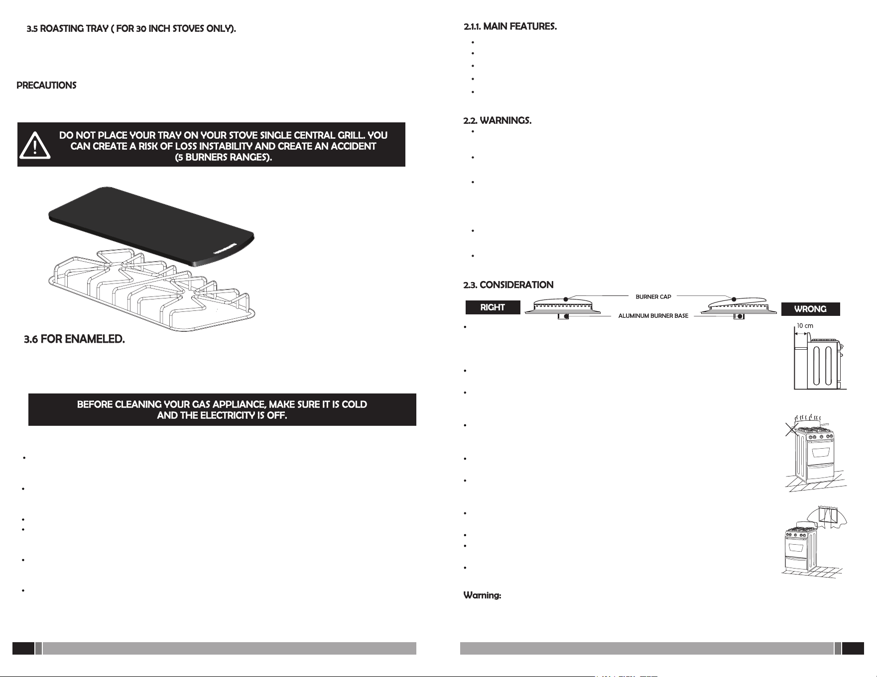
3.5 ROAST DRAWER TRAY
3.6 CLEANING MAINTENANCE
3.7. STAINLESS STEEL CARE
3.8. SAFETY PRECAUTIONS AND RESTRICTIONS ON USE
4. INSTRUCTIONS FOR CONVERSION TO DIFFERENT GASES
4.1.CHANGE OF INJECTORS
5. TROUBLESHOOTING
6. WARRANTY
Remember! You must read and fully implemennt the contents of this manual, also avoid
unqualified personnel to attempt to repair your appliance so you can enjoy longer and
prolong the life of your gas range.
Element Appliance Limited Warranty
(the “Products” or “Product” when referencing a singular product herein)
This Product (including any accessories included in the original packaging) as supplied and distributed in new condition, is
warranted by Element Appliance Company, LLC ("Element") to the original customer who purchases the Product from an
authorized Element retailer (the “Original Customer” or “you”) against defects in material and workmanship under proper use,
maintenance, and care according to the owner's manual, warnings, and instructions accompanying the Product (“Warranty”) as
follows:
* PLEASE NOTE – Proof of purchase evidencing the date of purchase by the Original Purchaser from an authorized Element
retailer (“Valid Proof of Purchase”) is required for all Warranty service. The express Warranty set forth herein is subject to all
terms and conditions set forth below.
1. WARRANTY SERVICE:
A. ONE-YEAR WARRANTY: Except as provided in subpart 1.B below, for a period of one (1) year from the date of purchase by the
Original Customer (the “Warranty Period”), if the parts or components covered by this Warranty are determined by Element or Element's
authorized service provider to be defective in material or workmanship, Element will, at its sole and absolute discretion and option: (i) repair the
defective part or component at no charge to the Original Customer, (ii) replace the defective Product with a new Product of similar or better
quality, at no charge to the Original Customer, or (iii) refund the documented purchase price paid by the Original Customer (excluding tax) to the
Original Customer upon return of the defective Product as directed by Element. After the Warranty Period expires, the Original Customer must
pay for all parts, components, shipping and handling, labor, and replacement costs associated with the Product or any part or component thereof,
regardless of any defects in the Product or any part or component thereof.
B. LIMITED EXTENDED WARRANTY THROUGH PRODUCT REGISTRATION: If and only if the Original Customer registers the Product
at www.elementelectronics.com within ninety (90) days of the date of purchase by the Original Customer, then the Warranty Period discussed in
subpart 1.A. above shall be extended an additional one (1) year to a new Warranty Period equaling two (2) years from the date of purchase by the
Original Customer. If the Product is not registered as provided for in this subpart 1.B, then the standard one-year Warranty Period set forth in
subpart 1.A shall apply.
C. TIMING AND PROCEDURE: Before Warranty service can commence, the Original Customer must contact either (i) the retailer from
whom the Original Customer purchased the Product, or (ii) Element directly, in either case for problem determination and service procedures. Valid
Proof of Purchase evidencing that the Product is within the Warranty Period MUST be presented by Original Customer in order to obtain the
requested Warranty service. Please have your model and serial number available, along with your date of purchase of the Product. To remain
eligible for Warranty service, Original Customer may not return the Product or any part or component thereof to the retailer or Element without
Element's prior written consent.
2. EXCLUSIONS AND LIMITATIONS TO WARRANTY SERVICE
The Warranty covers manufacturing defects in materials and workmanship of the Product encountered in the normal, non-commercial use of the
Product, and does not cover (a) damages or malfunctions resulting from improper or unreasonable use or maintenance, abuse, negligence, failure
to follow instructions contained in any written materials that accompany the Product, deterioration by reason of excess moisture, corrosive
atmosphere, lightning, power surges, connections to improper voltage supply, unauthorized alteration, or other external causes such as extremes in
temperature or humidity, modifications, scratches or discoloration; (b) any damage caused by using non-authorized parts or service facilities for
repair of Products (however, for avoidance of doubt, using non-authorized parts or service facilities will not, in and of itself, void the Warranty); (c)
transportation, shipping, delivery, pickup, insurance, installation, or set-up costs; (d) ordinary wear and tear, cosmetic damage, or damage due to
acts of nature, including but not limited to, water, floods, wind, storm, tornado, earthquake, or fire, or due to damage caused by extraordinary
impact events, such as dropping, crushing, demolition or other extraordinary damage; (e) commercial use of the Product, or use of the Product for
anything other than single-family household or residential use; or (f) modification of the Product or any part of the Product.
This Warranty is made to the Original Customer only and does not cover Products sold AS IS or WITH ALL FAULTS. The Warranty is invalid if the
factory-applied serial number has been altered or removed from the Product. This Warranty is valid only in the United States, and only applies to
Product if it was purchased and serviced in the United States. The addition of equipment or features to the Product that are not manufactured or
recommended by Element could affect the intended function of the Product, and therefore may void the Warranty. Furthermore, the exposure of
the Product to chemicals, heat, cold, humidity, or other elements can affect the Product components, and therefore, the Warranty does not cover
discoloration, fading, cosmetic changes, rust, or any damages or failure related to any such items. The Warranty is contingent upon the proper use,
maintenance, and care of the Product. The Warranty may be void if the Product has been used in a manner contradictory to, or in violation of, the
terms of the user's manual, warnings, or instructions accompanying the Product.
THIS WARRANTY IS MADE IN LIEU OF AND SUPERSEDES ALL OTHER WARRANTIES OR CONDITIONS OF MERCHANTABILITY OR FITNESS FOR
A PARTICULAR PURPOSE OR GENERAL USE, WHETHER EXPRESS, IMPLIED, COLLATERAL, STATUTORY, OR PROVIDED BY COMMON LAW,
THE UNIFORM COMMERCIAL CODE, OR OTHERWISE. ELEMENT FURTHER DISCLAIMS ALL WARRANTIES AFTER THE END OF THE
WARRANTY TERM DEFINED ABOVE. NO OTHER EXPRESS WARRANTY OR GUARANTY GIVEN BY ANY OTHER PERSON, FIRM, OR ENTITY
WITH RESPECT TO THE PRODUCT SHALL BE BINDING ON ELEMENT. REPAIR, REPLACEMENT, OR REFUND OF THE ORIGINAL PURCHASE
PRICE, AT ELEMENT'S SOLE DISCRETION, ARE THE EXCLUSIVE REMEDIES OF THE CUSTOMER.
ELEMENT SHALL NOT BE LIABLE FOR ANY INCIDENTAL OR CONSEQUENTIAL DAMAGES CAUSED BY THE USE, MISUSE, OR INABILITY TO USE
THE PRODUCT. THESE INCLUDE, BUT ARE NOT LIMITED TO, ANY DAMAGES IN THE FORM OF LOST PROFITS, LOSS OF USE, LEGAL FEES,
ECONOMIC LOSS, PERSONAL INJURIES, OR ANY OTHER DAMAGES CAUSED BY CIRCUMSTANCES BEYOND THE CONTROL OF ELEMENT.
NOTWITHSTANDING THE FOREGOING, ELEMENT'S AGGREGATE LIABILITY TO ANY CUSTOMER SHALL NOT EXCEED THE ORIGINAL
PURCHASE PRICE OF THE PRODUCT. THIS WARRANTY SHALL NOT EXTEND TO ANYONE OTHER THAN THE ORIGINAL CUSTOMER WHO
PURCHASED THE PRODUCT, AND IS NOT TRANSFERRABLE. NO PERSON IS AUTHORIZED TO ALTER, EXTEND, OR WAIVE THIS WARRANTY
OR ANY OF ITS TERMS OR CONDITIONS.
Some states do not allow the exclusion or limitation of incidental or consequential damages, or allow limitations on warranties, so the above
limitations or exclusions may not apply to you. This Warranty gives you specific rights, and you may have other rights, which vary from state to
state. The exclusions and limitations to the Warranty apply to the maximum extent permitted by law and unless restricted or prohibited by law.
Where any term of this Warranty is prohibited by applicable law, it shall be null and void, but the remainder of this Warranty shall remain in effect.
PLEASE DIRECT ALL CORRESPONDENCE TO:
Element Appliance Company, LLC
(888) 842-3577
https://elementelectronics.com
WARRANTY

3
/
24
22 /
24
RANGE SAFETY
WARNING:
1 LABELING INFORMATION
1.1. NAMEPLATE (See device nameplate) and is described as
WARNING: If the information in these instructions is not followed exactly a fire or
explosion may result causing property damage, personal injury or death.
• Do not store gasoline or other flammable vapors and liquids in the vicinity of this
or any other appliance.
WHAT TO DO IF YOU SMELL GAS
• Do not try to light any appliance Do not touch any electrical switch.
• Do not use any phone in your building.
• Immediately call your gas supplier from a neighbor's phone.
Follow the gas suppliers instructions.
• If you cannot reach your gas supplier, call the fire department.
• Installation and service must be performed by a qualified installer,
service agency.
• Never Operate the Top Surface Cooking Section of this Appliance Unattended Failure
to follow this warming statement could result in fire, explosion, or burn hazard that
could cause property damage, personal injury, or death.
• If a fire should occur, keep away from the appliance and immediately call your fire
department.
DO NOT ATTEMPT TO EXTINGUISH AN OIL/GREASE FIRE WITH WATER.
• The range will not tip during normal use. However, the range can tip if you apply too
much force or weight to the open door without the anti-tip bracket fastened down
properly.
TROUBLE
POSSIBLE CAUSE SOLUTION
The oven light
does not
turn on
The cylinder
The bypass valve is closed
The gas hose is bent or trapped
Burners clogged with dirt or water
Connect the range to the outlet
Check with a lamp that outlet has power
Change for a bulb of the same specification
Important Note: Make sure to follow instructions for installation, use, care and handling, referring
to the manual of your gas range. If problems persist, request service at one of the service center
according to the customer´s guide.
Range of height above sea level
at which the device is working
properly
This appliance is desingned to operate within the 2 and 2700 mas!
(meters above sea level).
The enclosure to install this appliance must have a volume of at least 35,5 cubic
meters (m3) for gas ranges of 20” (AB and AG) AND 53,6 cubic meters (m3) for gas
ranges of 30” (RG) When installed in conjunction with other devices must take into
account the power of all devices together to calculate the volume of available air
(see chapter 2). If the free volume of the enclosure to be installed on the device is
greater than or equal to the stated and there are not more gas appliances within the
same, then on air vents are required.
If there is a failure to comply with the above condition, the enclosure in which to
install this ranges must have permanent openings or vents with a minimum free area
of: 103,8 cm2 for 20” gas ranges (AB and AG) and 157,8 cm for 30” gas range (RG)
each (vents communicating to the outside atmosphere). When installed in
conjunction with other devices should take into account the power of all devices
together for the calculation of the vents (see chapter 2).
Minimum
volume
of the
installation
site:
Ventilation
required
for the
installation
site:
Emissions of carbon monoxide
levels for the installation site:
Emissions of carbon monoxide in this appliance shall not exceed:
2000 ppm (parts per million)
4
/
24
21
/
24
4
/
24
WARNING
Tip Over Hazard
YOUR SAFETY AND THE SAFETY OF OTHERS ARE VERY IMPORTANT.
This is the safety alert symbol.
This symbol alerts you to potential hazards that can kill or hurt you and others.
All safety messages will follow the safety alert symbol and either the word
DANGER
You can be killed or seriously injured if you don't immediately follow instructions.
WARNING
All safety messages will tell you what the potential hazard is, tell you how to reduce the
In the State of Massachusetts, the following installation instructions apply:
Installation and repairs must be performed by a qualified or licensed contractor, plumber
or gas fitter qualified or licensed by the state
of Massachusetts.
Acceptable Shut-off Devices: Gas Cocks and Ball Valves installed for use shall be listed.
A flexible gas connector, when used, must not exceed 4 feet (121.9 cm).
We have provided many important safety messages in this manual and on your appliance.
You can be killed or seriously injured if you don't follow instructions
•
•
•
Always read and obey all safety messages
“DANGER” or “WARNING.” These words mean:
chance of injury, and tell you what can happen if the instructions are not followed.
IMPORTANT: Do not install a ventilation system that blows air downward toward this gas
cooking appliance. This type of ventilatio n s y s t e m may cause ignition and combustion
problems with this gas cooking appliance resulting in personal injury or
unintended operation.
IMPORTANT SAFETY INSTRUCTIONS
WARNING:
To reduce the risk of fire, electric shock, or injury to persons when using the
appliance, follow basic precautions, including the folliwing;
WARNING 2:
DO NOT lean, step or sit on the doors of the grill or the product, this can
causeserious injuries and burns.
A child or adult can tip the range and be killed.
Install anti-tip bracket to floor or wall per installation instructions.
Slide range back so rear range foot is engaged in the slot of the anti-tip bracket.
Re-engage anti-tip bracket if range is moved.
Do not operate range without anti-tip bracket installed and engaged.
Failure to follow these instructions can result in death or serious burns to children
and adults.
gas leaks can not always be detected by smell.
Gas suppliers recommend that you use a gas detector approved by UL or CSA.
For more information, contact your gas supplier.
If a gas leak is detected, follow the “What to do if you smell gas” instructions.
- WARNING: TO REDUCE THE RISK OF TIPPING OF THE
RANGE, THE RANGE MUST BE SECURED BY PROPERLY
INSTALLED ANTI-TIP DEVICES.
TO CHECK IF THE DEVICES ARE INSTALLED PROPERLY,
SLIDE RANGE FORWARD, LOOK FOR ANTI-TIP
BRACKET SECURELY ATTACHED TO FLOOR OR WALL,
AND SLIDE RANGE BACK SO REAR RANGE FOOT IS
UNDER ANTI-TIP BRACKET..
UTENSIL HANDLES SHOULD BE TURNED INWARD AND
NOT EXTEND OVER ADJACENT SURFACE UNITS
– TO REDUCE THE RISK OF BURNS, IGNITION OF
FLAMMABLE MATERIALS, AND SPILLAGE DUE TO
UNINTENTIONAL CONTACT WITH THE UTENSIL, THE
HANDLE OF A UTENSIL SHOULD BE POSITIONED SO
THAT IT IS TURNED INWARD, AND DOES NOT EXTEND
OVER ADJACENT SURFACE UNITS.
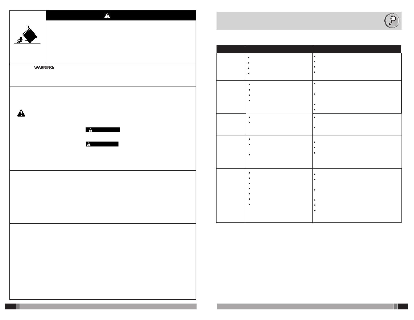
5 TROUBLESHOOTING
Your stove can present POTENTIAL FAILURE due to installation problems, misuse or improper
maintenance; check the following before calling for service.
PROBLEM
POSSIBLE CAUSE SOLUTION
The burners
do not star
Yellow flame
in burners
The cylinder
The bypass valve is closed
The gas hose is bent or trapped
Burners clogged with dirt or water
Lack of primary air to the burner
Poor location of the burner cover
The gas cylinder is ending
Holes burner or dogged with
Change the cylinder for a full one
Open the stopcock to the range
Leave the hose without kinks and unobstructed
Clean and dry the burners
Adjust the air as directed by the chapter called
graduation of the flame
Make sure the cover is properly positioned on
the burner
Change the cylinder for a full one
Clean the holes from burned or deposited foods
Check that all controls are closed
Call a qualified technician to check the hose
Call a qualified technician to check the status
of the clamps and connectors.
Connect the stove to the outlet
Check with a lamp that the outlet voltage is the
same in your stove
Thoroughly dry the spark plugs and the ignition
module.
Clean the metal tip of the spark plugs
Clean and dry burner gas exits
Place the lid properly to ensure the spark works
properly.
Adjust the air regulator as instructed by the
chapercalled graduation of the flame
Report to a qualified technician too adjust the
gas regulator
Detachment
of burner
flame
Gas smell
The electronic
ignition does
not work
Excess of primary air in the burner
High pressure gas
Opened stove controls
Loose or poorly connected hoses
to the stove
Clamps or loose connectorss
The stove is not connected
No power at outlet
The voltage is not adequate
Spark or ignition module is wet
Fouled sparck plugs
Burner obstructed by food or fat
Lid misplaced burner
20/
24
5
/
24
Electrical diagrams
WARNING
WARNING
Disconnect power before servicing.
Proper Installation: When installed, the appliance must
be electrically grounded in accordance with local codes, or
in the absence of local codes, with the National Electrical
Code, ANSI/NFPA 70 or the Canadian Electrical Code,
CSA C22.1-02. In Canada, the appliance must be electrically
grounded in accordance with Canadian Electrical Code.
Be sure your appliance is properly installed and grounded
by a qualified technician.
Caution: Label all wires prior to
disconnection when servicing controls.
Wiring errors can cause improper
and dangerous operation.
Verify proper operation after servicing.
Electrical grounding instructions:
This appliance is equipped with a
( three-prong) (four-prong) grounding
plug for your protection against shock
hazard and be plugged directly into a
properly grounded receptable.
Do not cut or remove the grounding
prong from this plug.
This appliance is equipped with a three-prong grounding
plug for your protection against shock hazard and should
be plugged directly into a properly grounded receptacle
Do not cut or remove the grounding prong from this plug.
NEVER use this appliance as a space heater to heat or
warm the room. Doing so may result in carbon monoxide
poisoning and overheating of the oven
NEVER cover any slots, holes or passages in the oven bottom
or cover an entire rack with materials such as aluminum foil.
Doing so blocks air flow through the oven and may cause
carbon monoxide poisoning. Aluminum foil linings may also
trap heat, causing a fire hazard.
CAUTION: Do not store items of interest to children in cabinets
above an appliance or on the backguard of an appliance.
Children climbing on the appliance to reach items could be
seriously injured.
Do Not Leave Children Alone - Children should not be left alone
or unattended in area where appliance is in use. They should
never be allowed to sit or stand on any part of the appliance.
Wear Proper Apparel – Loose-fitting or hanging garments
should never be worn while using the appliance.
*User Servicing – Do not repair or replace any part of the
appliance unless specifically recommended in the manual.
All other servicing should be referred to a qualified technician.
Injuries may result from the misuse of appliance doors or
drawers such as stepping, leaning, or sitting on the doors
or drawers.
Maintenance – Keep range area clear and free from
combustible materials, gasoline, and other flammable
vapors and liquids.
Top burner flame size should be adjusted so it does not
extend beyond the edge of the cooking utensil.
This instruction is based on safety considerations.
Do not use replacement parts that have not been
recommended by the manufacturer (e.g. parts made at
home using a 3D printer).
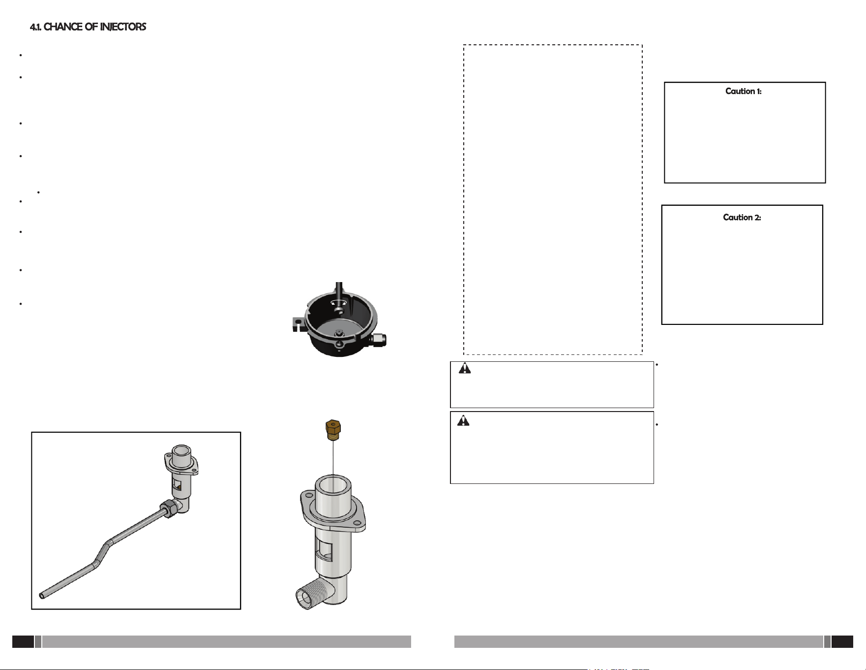
A. Burners with fuel system with ventury
To convert to another type of gas, the table must be dismantled and bridges with their venturys
loosening the respective screws to gain access to the injectors, which are located off the valves.
Use a socket wrench or face fixed 8 mm (5/16”) to remove it, and replace it with one marked
according to the above table, using chemical force lock down and verify with soapy water that it is
not a gas leak in the union.
B. Burners with fuel system with cup
The injectors are marked with a number that identifies the No. corresponding to each injector
calibrated diameter drill.
To convert to another type of gas remove the burners and access the injectors, which are located on
the inside of the cup-holder injector. Use a socket wrench or face fixed 8 mm (5/16”) for disassemble
and replace for one market according to the table of the manual, using low chemical work force
and verifying with soapy water that it is not a gas leak in the union.
To convert to another type of gas remove the burner oven. You need to remove the shelf (floor in
the oven) and remove the burner oven, dropping the front of the range.
Use a socket wrench or face fixed 7/16” to remove it and make the change of the injector labeled
according to the above table, using low chemical work force and verify with soapy water that it is
not gas leak in the union. Set the oven burner back into position ensuring that this is aligned.
Finally, perform the adjustment of the primary air burner as
described in section 2.4.4 and 2.4.5 “Graduation of the burner flame.”
Once all adjustment operations are finished, indicate with a label on
the gas appliance, the gas for which the appliance was regulated.
Note: This gas appliance accepts only modifications for use with
propane gas (LPG).
6
/
24
19/
24
SAVE THESE INSTRUCTIONS
Electrical Requirements
WARNING
Electrical Shock Hazard
Plug into a grounded 3 prong outlet.
Do not remove ground prong.
Do not use an adapter.
Do not use an extension cord.
Failure to follow these instructions can result in death,
fire, or electrical shock.
Gas Supply Requirements
WARNING
Explosion Hazard
Observe all governing codes and ordinances.
GAS RANGE
30”
MBAR
P.S.I
MINIMUM MAXIMUM
+ 0,087
- 0,058
0,42
1700 (17)
Pa (mbar)
2500 (25)
Pa (mbar)
2500 (25)
Pa (mbar)
3500 (35)
Pa (mbar)
+ 0,072
- 0,043
0,29
29
+6
-4
20
+5
-3
GAS RANGE
24”
TOP BURNERS
FAST
ULTRA
FAST
OVEN BURNER
GAS RANGE
20”
SUPPLY PRESSURES
(DRILL) Ø
INJECTOR
PROPANE GAS
(L.P.G)
NATURAL GAS
(N.G.)
GAS TYPE
TRIPLE CROWN INJECTOR
CENTRAL LATERALS
0.83 mm
1.3 mm
1.0 mm
1.5 mm
1.0 mm
1.5 mm
1.0 mm
1.4 mm
1.0 mm
1.5 mm
1.0 mm
1.5 mm
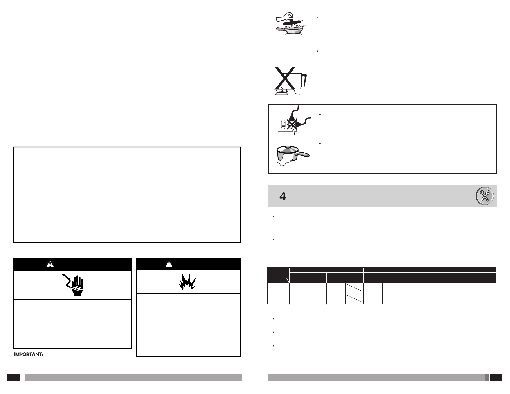
*Storage in or on Appliance – Flammable materials
should not be stored in an oven or near surface units.
* This appliance is not intended for storage
* Do Not Use Water on Grease Fires – Smother fire or
flame or use dry chemical or foam-type extinguisher.
* Use Only Dry Potholders – Moist or damp potholders
on hot surfaces may result in burns from steam. Do not
let potholder touch hot surface units. Do not use a
towel or other bulky cloth
* Never Leave Surface Units Unattended at High Heat
Settings – Boilover causes smoking and greasy
spillovers that may ignite.
* Glazed Cooking Utensils – Only certain types of glass,
glass/ceramic, ceramic, earthenware, or other glazed
utensils are suitable for range-top service without
breaking due to the sudden change in temperature.
* Clean Cooktop With Caution – If a wet sponge or
cloth is used to wipe spills on a hot cooking area, be
careful to avoid steam burn. Some cleaners can
produce noxious fumes if applied to a hot surface.
* Use Care When Opening Door – Let hot air or
steam escape before removing or replacing food.
* Do Not Heat Unopened Food Containers – Build-
up of pressure may cause container to burst and
result in injury.
* Keep Oven Vent Ducts Unobstructed
* DO NOT TOUCH HEATING ELEMENTS OR
INTERIOR SURFACES OF OVEN – Heating
elements may be hot even though they are dark in
color. Interior surfaces of an oven become hot
enough to cause burns. During and after use, do not
touch, or let clothing or other flammable materials
contact heating elements or interior surfaces of oven
until they have had sufficient time to cool. Other
surfaces of the appliance may become hot enough
to cause burns – among these surfaces are oven vent
openings and surfaces near these openings, oven
doors, and windows of oven doors
*Care must be taken to prevent aluminum foil and meat
probes from contacting heating elements. For self-
cleaning ranges –
* CAUTION:DO NOT LEAVE FOOD OR COOKING
UTENSILS, ETC., IN OVEN DURING THE PYROLYTIC
SELF-CLEANING MODE OF OPERATION.
*Do Not Clean Door Gasket – The door gasket is essential
for a good seal. Care should be taken not to rub, damage,
or move the gasket.
* Do Not Use Oven Cleaners – No commercial oven
cleaner or oven liner protective coating of any kind should
be used in or around any part of the oven.
* Clean Only Parts Listed in Manual.
* Before Self-Cleaning the Oven – Remove broiler pan
and other utensils. Wipe off all excessive spillage before
initiating the cleaning cycle.
* For units with ventilating hood.
Clean Ventilating Hoods Frequently - Grease should
not be allowed to accumulate on hood or filter
* When flaming foods under the hood, turn the fan
on.
*For smart enabled ranges and ovens
Remote Operation – This appliance is configurable
to allow remote operation at any time.
Do no store any flammable m a terials or
temperature sensitive inside, on top or near surface
units of the appliance.
MAKE SURE THE CONTAINER IS CENTERED WITH RESPECT TO THE
BURNER, THIS WAY YOU PREVENT ACCIDENTS OR DAMAGES IN A
SHORT PERIOD OF TIME OF YOUR GAS RANGE PARTS.
AVOID USING UNSTABLE UTENSILS OR WITH SIZES UNDER 100 MM
IN DIAMETER. DO NOT USE VESSELS WITH A CONVEX BASE OR
OUTGOING EDGES.
*USE VESSELS OF MAXIMUM 220 MM DIAMETER SIZE AS THIS
REDUCES THE AMOUNT YOU NEED AIR BURNER COMBUSTION
FILING A BAD RISK AND MONOXIDE POISONING TO YOUR GAS
RANGE
AVOID CONNECTING ANOTHER UNIT TO THE SAME POWER WHEN USING
YOUR ELECTRICAL COMPONENTS GAS RANGE, IT MAY CAUSE AND CREATE
AN OVERLOAD SHORT CIRCUIT.
USE YOUR OVEN GAS RANGE ONLY FOR COOKING FOOD
AVOID EXCESSIVE FLUID SPILL OF THE VESSELS; THEY CAN TURN OFF THE
FLAME OF BURNERS LEAVING GAS LEAK TO THE ENVIRONMENT.
INSTRUCTIONS FOR CONVERTING TO DIFFERENT GASES
It is necessary for all operations related to the installation, adjustment, adaptation to other
gas supply pressure and / or connection to the electricity network, to be performed by a
qualified installer, the gas company, or authorized personnel.
Your gas appliance leaves the factory to formal types of gas, if you want to use propane gas
(LPG) or natural (NG), a qualified technician will change injectors of the surface burners and
oven burner inlet and verify that the pressure of gas to the gas appliance are as indicated in
the following table:
For technical and safety reasons, parts to adapt your gas appliance to another type of gas and
/ or other supply pressure will be supplied by the manufacturer
The injectors are marked with a number that identifies the No. corresponding to each injector
calibrated diameter drill
Do not allow to drill the injectors change them with new ones
The range must be electrically grounded in accordance
with local codes and ordinances, or in the absence of local codes, with the
National Electrical Code, ANSI/NFPA 70 or Canadian Electrical Code, CSA
C22.1.Observe all governing codes and ordinances.
Use a new CSA International approved gas supply line.
Install a shut-off valve.
Securely tighten all gas connections.
If connected to propane, have a qualified person make
sure gas pressure does not exceed 14" (36 cm) water
column.
Examples of a qualified person include: licensed heating
personnel, authorized gas company personnel, and
authorized service personnel.
Failure to do so can result in death, explosion, or fire.
18 /
24
Install Anti-Tip Bracket
WARNING
Tip Over Hazard
Make Gas Connection
WARNING
Explosion Hazard
WARNING
Electrical Shock Hazard
Plug into a grounded 3 prong outlet.
Do not remove ground prong.
Do not use an adapter.
Do not use an extension cord.
Failure to follow these instructions can result in death,
fire, or electrical shock.
7
/
24
This range is equipped with an electronic ignition system
that will not operate if plugged into an outlet that is not
properly polarized.
If codes permit and a separate ground wire is used, it is
recommended that a qualified technician must
determine that the ground path is adequate.
A copy of the above code standards can be obtained
from: National Fire Protection Association 1 Battery
march Park Quincy, MA 02169-7471
CSA International
8501 East Pleasant Valley Road Cleveland, OH 44131-5575
A 120 V, 60 Hz, AC only, 15 A fused, ground and polarized is
also recommended.
It is recommended that a separate circuit serving only this
range be provided. Electronic ignition systems operate
within wide voltage limits, but proper grounding and
polarity are necessary. Check that the outlet provides 120
V power and is correctly grounded. This gas range is not
required to be plugged into a GFCI (Ground-Fault Circuit
Interrupter) outlet. It is recommended that you do not
plug an electric spark ignition gas range or any other
major appliance into a GFCI wall outlet as it may cause the
GFCI to trip during normal cycling. Performance of this
range will not be affected if operated on a GFCI-protected
circuit. However, occasional nuisance tripping of the GFCI
breaker is possible due to the normal operating nature of
electronic gas ranges. The tech sheet and wiring diagram
are located on the back of the range in a plastic bag.
IMPORTANT: This installation must conform with all
local codes and ordinances. In the absence of local codes,
installation must conform with the National Fuel Gas
Code ANSI Z223.1/NFPA 54 or, in Canada, the Natural
Gas and Propane Installation Code, CSA B149.1 - latest
edition.
IMPORTANT: Leak testing of the range must be
conducted according to the manufacturer's instructions.
Refer to the “Complete Connection” in the “Make gas
connection” section for the leak testing instructions.
Type of Gas
Natural Gas:
This range is factory set for use with Natural gas. See
“Gas Conversions” section. The model/serial rating plate
located on the oven frame behind of the oven door has
information on the types of gas that can be used. If the
types of gas listed do not include the type of gas
available, check with the local gas supplier.
Propane Gas Conversion:
Conversion must be done by a qualified service
technician. No attempt shall be made to convert the
appliance from the gas specified on the model/serial
rating plate for use with a different gas without
consulting the serving gas supplier. See “Gas Conversions”
section.
Gas Supply Line
Provide a gas supply line of 3/4" (1.9 cm) rigid pipe to
the range location. A smaller size pipe on longer runs
may result in insufficient gas supply. With Propane gas,
piping or tubing size can be 1/2" (1.3 cm) minimum.
Usually, Propane gas suppliers determine the size and
materials used in the system.
NOTE:Pipe-joint compounds that resist the action of
Propane gas must be used. Do not use TEFLON tape.
Tip Over Hazard A child or adult can tip the range and be
killed.
Install anti-tip bracket to floor or wall per installation
instructions. Slide range back so rear range foot is engaged in
the slot of the anti-tip bracket.
Re-engage anti-tip bracket if range is moved.
Do not operate range without anti-tip bracket installed and
engaged.
Failure to follow these instructions can result in death or
serious burns to children and adults.
Tip Over Hazard A child or adult can tip the range and be
killed.
Explosion Hazard Use a new CSA International approved gas
supply line. Install a shut-off valve. Securely tighten all gas
connections. If connected to propane, have a qualified person
make sure gas pressure does not exceed 14" (36 cm) water
column.
Examples of a qualified person include: licensed heating
personnel, authorized gas company personnel, and
authorized service personnel. Failure to do so can result in
death, explosion, or fire.
AVOID contact surface of the stainless steel with: Products such as battery acid, muriatic acid, ink
removers and similar, concentrated salt solutions, fat (mayonnaise, butter, etc.), or iron materials
(knives, pans, steel wool, etc.), because they produce color changes and oxidation problems arise.
This procedure creates difficult stains to remove, deteriorates the surface, and runs the risk of
damaging the finish. (Avoid large containers that can spread the flame to the stainless steel).
Do not leave items of common steel or iron in contact with the stainless steel, especially if they are
wet or damp
Note that the substances oxidized steel are: muriatic acid, sulfuric acid, iodine, pure ammonia,
bleach and chlorine derivatives
Your gas appliance has a stainless steel table, and note that by normal use and transfer of
heat from the burner to the table, it tends to become yellow in the burners, make further if are
generated liquid spills and these are carbonized to remove stubborn stains. (This effect is not part of
piece change by product warranty).
DO NOT LEAVE THE OVEN DOOR OPEN BECAUSE CHILDREN
CAN FIND THEM SITTING ON, BE INJURED OR CAN BE BURN
BY FOODS OR HOT LIQUIDS FROM THE RANGE TOP.
DO NOT USE YOUR GAS APPLIANCE TO HEAT A ROOM.
NO HANG OBJECTS IN INTERNAL GAS FACILITIES, OR USE
METAL PIPES AS GROUNDING ELECTRICAL CIRCUITS.
DO NOT ALLOW CHILDREN PLAY OR MOVE CLOSER WHEN
GAS RANGE IS ON. THEY MAY SUFFER BURNS.
NEVER LEAVE OBJECTS ON THE GAS RANGES THAT CHILDREN
MAY NEED OR WANT.
NEVER LEAVE GASOLINE OR OTHER FLAMMABLE FLUID NEAR
YOUR GAS RANGE
IN CASE A FIRE STARTS DUE TO GREASE IN THE VESSELS THAT
ARE ON THE GAS RANGE DO EXTINGUISH IT WITH WATER,
COVER IT WITH A MEAL CAP
ALL POTS AND PANS HANDLES MUST STAY OUT OF REACH
17
/
24
8
/
24
Backguard
Grates
Cooktop
1. Burner cover.
2. Burner.
3. Injector holder cup (fisto)
4. Conduction pipes.
5. Manifold pipe.
6. Safety valve, with fitting.
7. Injector (fisto).
8. Oven thermostat control or safety
valve (depending on model)
6
5
1
2
4
3
7
DETAIL (COMBUSTION SYSTEM WITH CUP) (According to references) Figure No. 3.
DETAIL (MIX TYPE COMBUSTION SYSTEM) (According to references) Figure No. 2.
NOTE: Locate the electrical diagram for your gas stove on the back of your gas appliance.
Figura No. 3
Figura No. 2
1
2
4
10
8
6
11
12
13
3
14
9
7
5
5
8
1. Upper burner cover.
2. Aluminum burner base.
3. Mixer.
4. Furnace conduction tube
.5. Long conduction tube.
6. Short conduction tube.
7. Safety valve with fitting.
8. Oven control (depending on model).
9. Manifold tube.
10. Injector elbow oven.
11. Oven injector.
12. Oven burner air regulator.
13. Oven burner.
14. Oven burner ignition tube.
TECHNICAL INSTRUCTIONS
Keep the electrodes and the connections of the electronic ignition system well cleaned, preventing
that accumulation of grease, water or food scraps to prevent the passage of gas or spark
ignition burners.
To restore the shine on brass caps use a powder detergent and water with steel wool, or use
products to shine metals get into the trade. It is normal that brass caps turn black after use.
3.7 CARE OF STAINLESS STEEL
Stainless steel is a material easy to care for. With proper cleaning can keep its original features.
THE SECRET OF CLEANING AND MAINTENANCE IS IN THE PROPER
PRODUCTS AND PROCEDURES AND CARE TO HANDLE THE PRODUCT.
For stubborn dirt, begin with mild cleaning methods. Be patient and repeat a reasonable number of
times before resorting to harsher cleaning procedures.
The best methods to conserve stainless steel are water, soap, soft, neutral
detergent and ammonia-based removers diluted in warm water. Apply
them with a soft cloth or sponge fine nylon, rinse with water and dry with a
soft cloth. Drying is important to avoid the presence of stains on the
surface. Routine cleaning easily removes common stains from constant use.
When routine cleaning is not enough, apply baking soda and diluted
household alcohol to form a paste, use a soft cloth or nylon brush. Use a soft
bristle brush. To avoid scratching the surface must be made long, even
strokes in the direction of the grain of the piece (avoid circular motions)
finally rinse with water and dry with a soft cloth.
Take a pre-wash with mild detergent and warm or hot water, or in a
solution of ammonia based remover and water. If this does not remove
burned or charred food deposits, use removers based on caustic soda.
Follow the procedure for moving light stains and repeat it if necessary. If
the stain persists, use nonmetallic fine abrasives. Finally, rinse and continue
routine cleaning.
Grates
(in)
Grates
20.07
20.07
20.07
35.43
35.43 35.43
21.06 22.83 22.83
29.92
29.92
25.19
25.19
28.34
27.75
9
/
24
16 /
24
ENAMEL SHEET TRAY
-Your range has a control that does not allow simultaneous use of the gas oven and broiler resistance
-When using the grill, it is recommended to be careful to avoid touching the resistance inside the oven
The gas appliances (gas-powered devices) should receive periodic cleaning and complete
maintenance every twelve months, in order to avoid gas leakes in joints and connections of
the appliance.
Wear gloves to perform the following procedures:
For enameled or painted parts of your gas appliance, such as surface burner, control panel, sides,
doors, glass oven window and knobs, use hot soapy water with a soft cloth.
Plastic parts of your gas appliance should NOT use solvents or products that are based on alcohols,
such as: isopropanol toluene, methylene chloride, methyl.
For the burners and grates, use hot soapy water in a plastic scouring pad.
DO NOT use anything that may scratch the surfaces of your gas appliance, such as screwdrivers,
knives, etc.
NEVER USE ABRASIVE CLEANERS, or any kind of metal fibers as these will permanently damage
the surface of your range.
Do not use steam cleaners on gas appliances with electrical connections for power electronic ignition.
For cleaning the oven, use hot soapy water with a plastic scouring pad.
You can also use commercial oven cleaner following the package instructions.
Be careful not to use products based on caustic soda for cleaning enameled parts.
To make their roast place the tray on the upper grills covering two bruners. Use a low flame for
cooking to avoid overheating. Be sure to fit your tray on the grill ( see picture depending on model).
BURNER CONTROL SAFETY VALVE, EASY HANDLING AND CLEANING.
THERMAL INSULATION IN OVEN GLASS DOOR FOR SAFETY AND GAS ECONOMY.
OVEN DOOR WITH DOUBLE GLASS TEMPERED SAFETY.
SHELF (GRILL OVEN) ADJUSTABLE IN VARIOUS POSITIONS.
AVAILABLE FOR PROPANE GAS (LPG) AND NATURAL GAS (NG).
FINISHED: ENAMEL AND PAINT.
Before installation, make sure the gas supply pressure is appropriate for the type of gas
that is regulated to the gas appliance.
The data setting for this gas appliance is on the nameplate and label located in the
appliance
This gas appliance is not designed to be connected to a device for disposal of combustion
products. This must be installed and connected according to the installation requirements in
force. Attention should be given to the relevant requirements of ventilation. (See next
paragraph).
To manipulate correctly, this gas appliance needs to be adjusted according to local
conditions of atmospheric pressure and room temperature. See 2.4.4.
The room where you are installing, must contemplate the ventilation conditions contained
accordingly by current.
For range models that have aluminum burners, note that if you incur in the wrong
position as shown in the graph, based burner cause the aluminum to deform in a short
period.
Be sure to ensure good leveling of your stove to prevent the containers placed grills
slide.
Between the range and the back wall should be a minimum distance of 10 cm to
prevent the pipe or gas supply hose undergoes deformations, base burner may cause
the aluminum.
Do not install this or any other gas appliance in bathrooms, shower rooms, basements,
bedrooms or places that allow the accumulation of an explosive mixture of gas - air,
or high levels of combustion products.
Do not install your gas appliance in a place that is exposed to strong air currents, they
can turn off the burners.
Flexible connections based elastomers should not be in contact with hot parts of your
range or passing through the exhaust of the range, so DO NOT cross the hose behind
the appliance.
LOCATE your range at a safe distance from the fridge or washing machine, can
decrease the performance and lifetime of these.
DO NOT place your range near window with curtains or fuel materials.
The length of the flexible connection should be as short as possible and in any case
must be greater than 1.5 meters.
Your gas appliance should be located near the power outlet, in order not to
use additional extensions.
Do not use for your stove a wheeled base. Install it in accordance with Section 2.4.2
of this manual.
10
/
24
15 /
24
(30 in) (762mm)
A manual valve must be
installed in an accessible
location on the gas pipe
external to the appliance in
order to be able to open or
close the gas to the
appliance externally.
- All openings in the wall
behind the appliance and in
the floor beneath the
appliance must be sealed.
18 In
18 In
457 mm
457 mm
If your built-in oven has
a light in the oven, it is connected to 120 volts (60 Hz), use a maximum of a 25 watt/120 V light
bulb. To change the light, remove the glass protector on the inside of the oven, unscrewing it
from the base. Replace the bulb and replace the glass protector.
For the porcelain parts of your electric oven, control panel, sides, doors, oven window glass and
knobs, use a soft cloth with hot soapy water.
Ÿ For the plastic parts of your electric oven, solvents or alcohol-based products such as:
Toluene, Isopropanol, Methylene Chloride, Methylethyl Ketone should NOT be used.
Ÿ To clean the heating elements, use a slightly damp cloth and soap.
Ÿ For electric oven racks, use hot, soapy water on a plastic sponge.
Ÿ DO NOT use objects that may scratch the surfaces of your electric oven, such as screwdrivers,
blades, spatulas, etc.
NEVER use abrasive detergents or any type of fibers, as these will permanently damage the
surface of your electric oven.
Ÿ To clean the oven, use hot soapy water on a plastic sponge. You can also use commercial
oven cleaner following the instructions on the package. Be careful not to use products based
on caustic soda to clean enameled parts.
If the cord is damaged it must be replaced by a special cord or assembly available from the
manufacturer.
Once you have finished the cooking process of your food and if you want to broil, follow the
instructions below.
Turn off the oven burner (gas), otherwise will not work the grill resistance, pull the broiler switch
located on the control panel of your stove, this energizes the broiler resistance.
If you want to make the broil after baking, you do not need to preheat your oven, otherwise
make a 5 minute preheat before placing food.
Check the broiling time by following the directions on your prescription or experience in the
handling.
Once the process of broiling is finished, turn the switch to complete the operation. Remember
that before you can finish the operation off the resistance and the residual heat in the oven will
finish cooking thus saving energy.
PRECAUTIONS
Your range has a control that does not allow simultaneous use of the gas oven and broiler
resistance -When using the grill, it is recommended to be careful to avoid touching the resistance
inside the oven
If your gas appliance is fitted with a tempered glass lid observe the following safety warning
"Caution: Cover glass can shatter when heated. Turn all burners before shutting the lid." Any
liquid spilled on the cover glass must be cleaned before opening.
Flexible connections based elastomers should not be in contact with hot
parts of your range or passing through the exhaust of the range. DO NOT
cross the hose behind the appliance.
LOCATE your range at a safe distance from the fridge or washing machine,
as this can decrease the performance and lifetime of the appliances.
The length of the flexible connection should be as short as possible and in
any case must be greater than 1.5 meters.
Your gas appliance should be located near the power outlet, in order not
to use additional extensions.
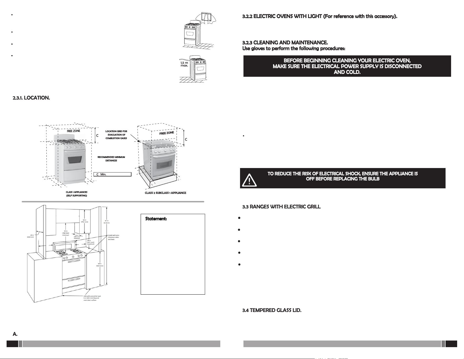
Make sure your gas range is kept in an area free of any combustible material, such as
wood, paper and plastics. The minimum distances to keep your stove off adjacent
walls are shown in the following figure.
For Class 2 subclass 1 appliances, the installation must be on a hard masonry base for total
support of the oven floor and a height to ensure that the table is level cabinet or countertop
(Drawing above). Additionally, grids must have ducts for gas combustion gases evacuation as
indicated indicated in the above drawing and numeral 2.3.
Anchorage of class 1 and class 2 subclass 1 gas appliances (View description paragraph 2.4.2)
14 /
24
11 /
24
INSTRUCTIONS FOR USE AND MAINTENANCE
STARTING THE ELECTRIC OVEN.
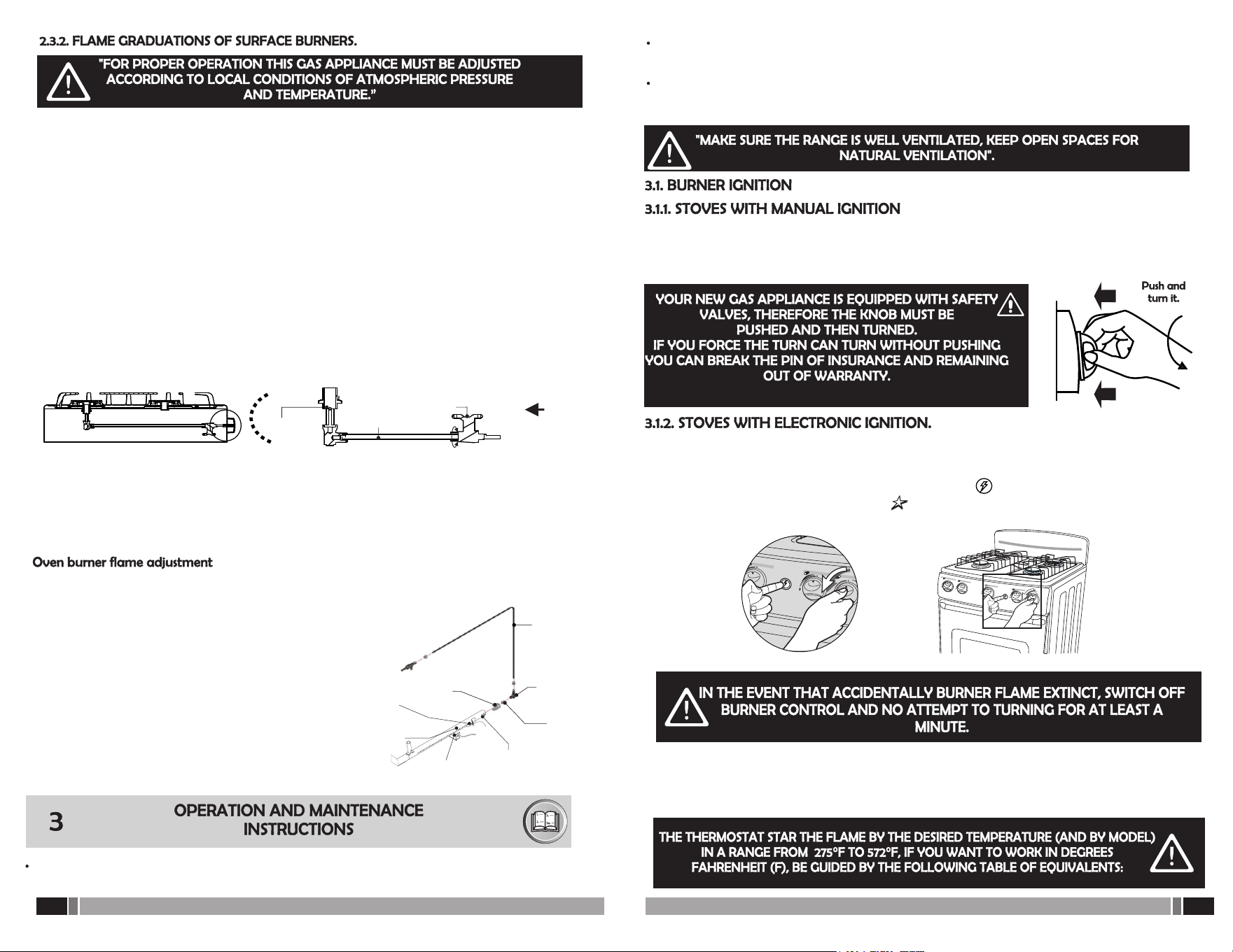
Select the temperature by rotating the thermostat knob clockwise. To turn off, return the knob
to the indicated mark (initial). Never force the knob to turn, you may break the safety pin. The
thermostat is responsible for controlling the internal temperature of the oven, keeping the
temperature selected by you constant. After selecting the temperature, do the same with the
adjacent knob and choose the heat source like this:
To start cooking, it is recommended to preheat, first placing the oven at maximum
temperature for 10 to 15 minutes and then setting the desired temperature before introducing
the food. When the pilot light goes out, it indicates that the oven has reached the selected
temperature. While the oven is operating the pilot light will turn on and off several times.
3.2.1 GENERAL RECOMMENDATIONS FOR USE OF YOUR OVEN:
Once you turn on your built-in electric oven, it will be ready for normal operation. Your oven's
thermostat control allows you to set the desired temperature according to the scale printed on
your oven's control panel. Regarding the arrangement of food inside the oven, it is advisable to
leave a minimum space of 3 to 5 cm between the edges of the containers and the eastern walls;
This will ensure normal and uniform heat circulation. Please note that the maximum load for the
oven racks is 22 pounds.
The optimal operation of the oven depends on following the instructions of each recipe and your
good experience in handling it.
The upper resistance turns on.
The lower resistance turns on.
The 2 resistors are turned on simultaneously.
IMPORTANT:
(Antitip restraint)
“A child or adult can tip the range and be killed.”b) “Install the anti-tip device to the structure
and/or the range. Verify the anti-tip device has been properly installed and engaged [state how
for the two or more possible locations].”c) The anti-tip system must always be in place, for this
reason if you must move the product from place to place you must anchor the product to the
wall again.d) “Re-engage the anti-tip device if the range is moved. Do not operate the range
without the anti-tip e) “See installation instructions for details.”f) “Failure to do so can result in
death or serious burns to children or adults.”
Top cover must be open
when main burner is in
operation.
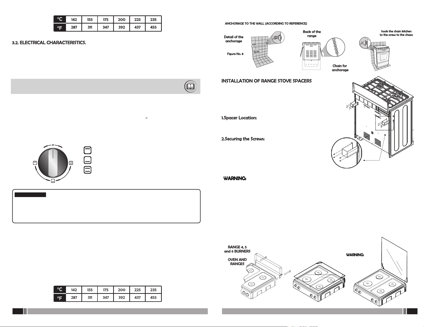
The range stove spacers are designed to maintain an
appropriate distance between the stove and the wall,
enhancing the safety and performance of the
appliance. Below are the steps for the correct
installation of the spacers:
The spacers should be placed on
the back of the range stove, specifically on the sides
of the back panel as shown in the image.
To secure each spacer, use four
screws. Insert the screws into the corresponding holes
on the spacers and tighten them firmly to the back
panel of the range stove.
Once the spacers are installed, check that they are
firmly secured.
B. Installation of the backguard
Using screws that come in your range, install the backguard matching the holes in the packets to
the side at the rear of the stove or the media bridge (according to the model, see graphs).
If your gas appliance has an oven light or electronic ignition, make sure it is connected to a 120
volts (60 cycles) (Shot with grounding).
Use a bulb maximum 25 watts/120 V. (If the model has it).
To change, remove the glass shield by unscrewing the base, change the bulb and replace the
protector.
12 /
24
13 /
24
Elbow
Injector Oven
Injector
Oven
Regulator
of air
Tube
Switched on
Burner
Oven
Regulation
windowof air
Spark
plug
Thermocouple
Remove the removable oven floor (shelf)
by pulling up and then in.
Carry out the adjustment with the burner
off and light the burner observing the
flame.Be guided by the attached graph.
Finally, replace the removable oven floor.
Mixer
Tube
Driving
Valve
OPEN WINDOW: MORE AIR
CLOSED WINDOW: LESS AIR
SYSTEM
MIX
This product does not need to be adjusted for its correct operation in the different environmental
conditions, temperature or altitude (2 to 2700 m.a.s.l)
For technical and safety reasons, the parts to adapt your stove to another type of gas and/or
another supply pressure will be supplied by the manufacturer.
For the oven, carry out the same operation as with the upper burners of the ventury system.
The regulator is located at the rear of the oven burner.
For your gas appliance to function optimally, the burner flame should be blue, keeping an
alive and stable appearance. If the flame presents yellow tips is due lack of primary air to gas -
air mixture, therefore you must open the air regulator.
If the flame tends to separate the burner flames featuring vibrant violet shade is due excess
primary air, in which case you must close the air regulator.
In both cases, the air must graduate in the burner as follows:
(for stoves with burner ventury tube).
1. Shut off the main gas supply
2. Loosen the screws holding the keypad and slide forward (if you have any electrical
connection, take care not to loosen the cables).
3. Graduate air intake according to what was observed in the flame, turning the air regulator
located on the Ventury tube to the outlet of the valve opening or closing the window air
reception located in the tube. (Use screwdriver to lock and unlock the screw of the air
regulator).
Before using your gas appliance make sure that the enclosure where you will install, meets the
ventilation air requirements of clause 2.3 of this manual.
After connecting the gas supply, either the cylinder or network, verify that all the knobs are in
the off position and turn on your gas appliance gas.
If your gas appliance model requires it, the gas appliance must be anchored, as indicated in
section 2.4.2 paragraph A of this manual.
If your range is with manual ignition, hold a match or a spark to the burner you want to use
and at the same time press the knob for the burner and turn it to the left (counterclockwise)
until the flame position low (if model has it).
Before the ignition, make sure the power source is connected to power at 120 volts (60 cycles)
and that is producing a spark in each of the spark plugs located on the burners.
To operate the ignition, star the electronic ignition button while pressing and simultaneously
turn the knob to the position of low flame. If you turn the knob does not return to its starting
position and repeat, once lit the burner release the switch.
Note: if your stove has brass burner caps, note that for the purposes of use, liquid spills and direct
contact with the burner flame, it tends to lose its shiny appearance, which is a natural condition
in this type of material without affecting the operation of your gas appliance. To recover its
original condition see ítem 3.6 “Cleaning and Maintenance”