Translation of the Original Operating Manual
Operating Manual
Ultra Low Temperature Freezer SUFsg
Read the operating manual prior to commissioning
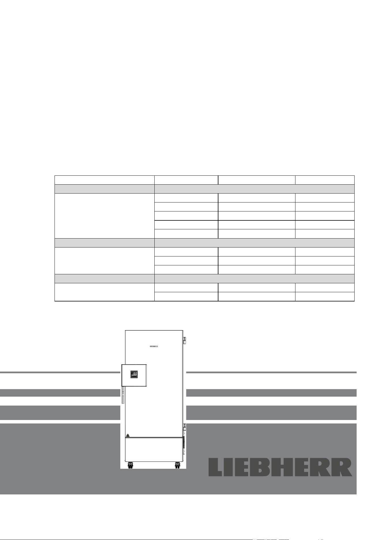
Model
Gross content in liters
Voltage
SUFsg 3501,001
402
230 V
SUFsg 5001,001
491
230 V
SUFsg 7001,001
728
230 V
SUFsg 5001,123
491
208-230 V
SUFsg 7001,123
728
208-230 V
UL chambers
SUFsg 3501,137
402
115 V
SUFsg 5001,137
491
115 V
SUFsg 7001,137
728
115 V
Chambers with water cooling
SUFsg 5001,H72
491
230 V
SUFsg 7001,H72
728
230 V
SUFsg 3501
SUFsg 5001
SUFsg 7001
7083 438-00

SUFsg 12/2024 Page 2/112
Contents
1. SAFETY .................................................................................................................. 6
1.1 Personnel Qualification ....................................................................................................................... 6
1.2 Operating manual ................................................................................................................................ 6
1.3 Legal considerations ........................................................................................................................... 6
1.3.1 Intellectual property ................................................................................................................... 7
1.4 Structure of the safety instructions ...................................................................................................... 7
1.4.1 Signal word panel ...................................................................................................................... 7
1.4.2 Safety alert symbol .................................................................................................................... 8
1.4.3 Pictograms ................................................................................................................................. 8
1.4.4 Word message panel structure ................................................................................................. 9
1.5 Localization / position of safety labels at the chamber ....................................................................... 9
1.6 Type plate.......................................................................................................................................... 10
1.7 General safety instructions on installing and operating the chamber ............................................... 11
1.8 Intended use ..................................................................................................................................... 13
1.9 Foreseeable Misuse .......................................................................................................................... 15
1.10 Residual Risks .................................................................................................................................. 15
1.11 Operating instructions ....................................................................................................................... 17
1.12 Measures to prevent accidents ......................................................................................................... 17
2. CHAMBER DESCRIPTION .................................................................................. 18
2.1 Chamber overview ............................................................................................................................ 20
2.2 Door lock and controller housing ...................................................................................................... 22
2.2.1 Operating the door lock ........................................................................................................... 22
2.3 Main power switch ............................................................................................................................. 23
2.4 Chamber rear .................................................................................................................................... 24
2.5 Doors ................................................................................................................................................. 25
2.5.1 Outer door ............................................................................................................................... 25
2.5.2 Compartment doors ................................................................................................................. 25
3. COMPLETENESS OF DELIVERY, TRANSPORTATION, STORAGE, AND
INSTALLATION .................................................................................................... 26
3.1 Unpacking, and checking equipment and completeness of delivery ................................................ 26
3.2 Guidelines for safe lifting and transportation ..................................................................................... 27
3.2.1 Moving the freezer inside a building ........................................................................................ 27
3.2.2 Transport outside a building .................................................................................................... 28
3.3 Storage .............................................................................................................................................. 29
3.4 Location of installation and ambient conditions ................................................................................ 29
4. INSTALLATION AND CONNECTIONS ............................................................... 31
4.1 Operating instructions ....................................................................................................................... 31
4.2 Spacers for rear wall distance ........................................................................................................... 31
4.3 Support feet (SUFsg 3501only) ........................................................................................................ 31
4.4 Adjustable shelves ............................................................................................................................ 32
4.5 Connections of cooling water for chambers with water cooling ........................................................ 34
4.5.1 Connection of cooling water outlet for water cooling ............................................................... 34
4.5.2 Connection of cooling water inlet for water cooling ................................................................. 35
4.5.3 Connection kit for cooling water .............................................................................................. 35
4.6 Electrical connection ......................................................................................................................... 37
5. FUNCTIONAL OVERVIEW OF THE CHAMBER CONTROLLER ....................... 38
5.1 Menu structure of the controller and access levels ........................................................................... 39
6. START UP ............................................................................................................ 40
6.1 Preset factory parameters ................................................................................................................. 40
6.2 Behavior after turning on the chamber .............................................................................................. 40

SUFsg 12/2024 Page 3/112
7. TEMPERATURE SET-POINT ENTRY ................................................................. 41
7.1 Setting the Manual Offset value ........................................................................................................ 42
8. PLACING SAMPLES IN STORAGE IN THE FREEZER ...................................... 43
9. SETTING SPECIAL CONTROLLER FUNCTIONS .............................................. 44
10. PASSWORD ......................................................................................................... 45
10.1 Password request ............................................................................................................................. 45
10.2 Assign and modify a password ......................................................................................................... 45
10.2.1 Assign and modify the User password .................................................................................... 46
10.2.2 Assign and modify the Admin password ................................................................................. 46
10.3 Performance during and after power failure and shut down ............................................................. 47
11. SAFETY CONTROLLER (TEMPERATURE SAFETY DEVICE) .......................... 47
11.1 Setting the safety controller mode .................................................................................................... 48
11.2 Setting the safety controller value ..................................................................................................... 48
11.3 Message and measures in the state of alarm ................................................................................... 49
11.4 Function check .................................................................................................................................. 49
12. GENERAL CONTROLLER SETTINGS ................................................................ 50
12.1 Selecting the controller’s menu language ......................................................................................... 50
12.2 Selecting the temperature unit .......................................................................................................... 50
12.3 Setting the current date ..................................................................................................................... 51
12.4 Setting the current time ..................................................................................................................... 52
12.5 Function “Language selection at restart” .......................................................................................... 52
12.6 Setting the chamber address ............................................................................................................ 53
12.7 Display brightness ............................................................................................................................. 53
13. SETTING THE ALARM LIMIT FOR RANGE ALARM AND THE ALARM DELAYS
.............................................................................................................................. 54
13.1 Setting the delay time for door open alarm ....................................................................................... 54
13.2 Setting the delay time for range alarm .............................................................................................. 54
13.3 Setting the alarm limit of the range alarm ......................................................................................... 55
14. ALARM FUNCTIONS ........................................................................................... 56
14.1 Alarm messages ............................................................................................................................... 56
14.2 Information messages ....................................................................................................................... 58
14.3 Activating / deactivating the audible alarm (alarm buzzer) ............................................................... 58
14.4 Required actions in case of an alarm ................................................................................................ 59
14.4.1 Safety controller temperature alarm ........................................................................................ 59
14.4.2 Temperature range alarm (too high and too low temperature) ............................................... 59
14.4.3 Door open alarm ...................................................................................................................... 60
14.4.4 Power failure alarm .................................................................................................................. 60
14.4.5 Messages on the battery management system ...................................................................... 61
14.4.6 Messages referring to temperature sensor failure .................................................................. 62
14.4.7 Messages referring to CO
2
emergency cooling (option CO
2
emergency cooling) .................. 63
14.5 Zero-voltage relay alarm output ........................................................................................................ 64
15. ETHERNET NETWORK SETTINGS .................................................................... 65
15.1 Showing the network settings ........................................................................................................... 65
15.1.1 Showing the chamber’s MAC address .................................................................................... 65
15.1.2 Showing the IP address........................................................................................................... 65
15.1.3 Showing the subnet mask ....................................................................................................... 66
15.1.4 Showing the standard gateway ............................................................................................... 66
15.1.5 Showing the DNS server address ........................................................................................... 66
15.1.6 Showing the DNS chamber name ........................................................................................... 67

SUFsg 12/2024 Page 4/112
15.2
Changing the configuration of the network settings .......................................................................... 67
15.2.1 Selecting the type of IP address assignment (automatic / manual) ........................................ 67
15.2.2 Selecting the type of assignment of the DNS server address (automatic / manual) ............... 68
15.2.3 Assigning the IP address ......................................................................................................... 68
15.2.4 Setting the subnet mask .......................................................................................................... 69
15.2.5 Setting the standard gateway .................................................................................................. 69
15.2.6 Assigning the DNS server address ......................................................................................... 70
16. DATA RECORDER .............................................................................................. 70
16.1 Recorded data ................................................................................................................................... 70
16.2 Storage capacity ............................................................................................................................... 71
16.3 Setting the storage rate for the “DL1” recorder data ......................................................................... 71
16.4 Deleting the data recorder................................................................................................................. 71
17. USB-MENU: DATA TRANSFER VIA USB INTERFACE ..................................... 72
17.1 Connecting the USB stick ................................................................................................................. 72
17.2 Import function .................................................................................................................................. 72
17.3 Export functions ................................................................................................................................ 73
17.4 Ongoing data transfer ....................................................................................................................... 73
17.5 Error during data transmission .......................................................................................................... 74
17.6 Removing the USB stick ................................................................................................................... 74
18. BATTERY MANAGEMENT SYSTEM .................................................................. 74
18.1 Battery operation ............................................................................................................................... 74
18.2 Charging voltage ............................................................................................................................... 75
19. SETTING AND ACTIVATING THE SERVICE SETPOINT ................................... 75
19.1 Setting the service setpoint ............................................................................................................... 75
19.2 Activating the service setpoint........................................................................................................... 76
20. CO
2
EMERGENCY COOLING (OPTION FOR SUFSG 5001, SUFSG 7001) ...... 77
20.1 Connecting and exchanging the pressurized CO
2
cylinder............................................................... 78
20.2 Operating the CO
2
emergency cooling system ................................................................................. 80
20.3 Settings on the chamber controller ................................................................................................... 81
20.3.1 Setting the CO
2
emergency cooling temperature setpoint ...................................................... 82
20.3.2 Activating the CO
2
emergency cooling .................................................................................... 82
20.3.3 Test run of the CO
2
emergency cooling .................................................................................. 83
21. DATA MONITORING AND RECORDING ............................................................ 84
21.1 Ethernet interface .............................................................................................................................. 84
21.2 Analog output for temperature (option) ............................................................................................. 84
22. CHAMBER INVENTORY: STORAGE RACK SYSTEMS AND CRYO BOXES
(OPTION) .............................................................................................................. 85
22.1 Storage rack systems with or without cryo boxes ............................................................................. 85
22.2 Cryo boxes ........................................................................................................................................ 85
23. CLEANING AND DECONTAMINATION .............................................................. 86
23.1 Cleaning ............................................................................................................................................ 86
23.2 Decontamination / chemical disinfection ........................................................................................... 88
24. MAINTENANCE AND SERVICE, SERVICE, TROUBLESHOOTING, REPAIR,
TESTING .............................................................................................................. 89
24.1 General information, personnel qualification..................................................................................... 89
24.2 Maintenance work by the customer .................................................................................................. 90
24.2.1 Checking and cleaning / replacing the condenser air filter...................................................... 90
24.2.2 Cleaning the condenser........................................................................................................... 91
24.2.3 De-icing and defrosting............................................................................................................ 91

SUFsg 12/2024 Page 5/112
24.2.4
Maintenance of the door lock .................................................................................................. 92
24.3 Maintenance intervals, service .......................................................................................................... 93
24.4 Service Reminder .............................................................................................................................. 93
24.5 Simple troubleshooting ...................................................................................................................... 94
24.6 Sending the chamber back ............................................................................................................... 96
25. DISPOSAL............................................................................................................ 97
25.1 Disposal of the transport packing ...................................................................................................... 97
25.2 Decommissioning .............................................................................................................................. 97
25.3 Disposal of the chamber in the member states of the EU ................................................................ 97
25.4 Disposal of the chamber in non-member states of the EU ............................................................... 99
26. TECHNICAL DESCRIPTION ................................................................................ 99
26.1 Factory calibration and adjustment ................................................................................................... 99
26.2 Over current protection ..................................................................................................................... 99
26.3 Technical data ................................................................................................................................. 100
26.4 Equipment and options, accessories and spare parts (extract) ...................................................... 103
26.5 Dimensions SUFsg 3501 ................................................................................................................ 105
26.6 Dimensions SUFsg 5001 ................................................................................................................ 106
26.7 Dimensions SUFsg 7001 ................................................................................................................ 107
27. EU DECLARATION OF CONFORMITY ............................................................. 108
28. CONTAMINATION CLEARANCE CERTIFICATE ............................................. 109
SUFsg 12/2024 Page 6/112
Dear Customer,
For the correct operation of the SUFsg ultra-low temperature freezer, it is important that you read this
operating manual completely and carefully and observe all instructions as indicated. Failure to read, under-
stand and follow the instructions may result in personal injury. It can also lead to damage to the chamber
and/or poor equipment performance.
1. Safety
1.1 Personnel Qualification
The chamber must only be installed, tested, and started up by personnel qualified for assembly, startup,
and operation of the chamber. Qualified personnel are persons whose professional education, knowledge,
experience and knowledge of relevant standards allow them to assess, carry out, and identify any potential
hazards in the work assigned to them. They must have been trained and instructed, and be authorized, to
work on the chamber.
The chamber should only be operated by laboratory personnel especially trained for this purpose and fa-
miliar with all precautionary measures required for working in a laboratory. Observe the national regulations
on minimum age of laboratory personnel.
1.2 Operating manual
This operating manual is part of the components of delivery. Always keep it handy for reference in the
vicinity of the chamber. If selling the unit, hand over the operating manual to the purchaser.
To avoid injuries and damage observe the safety instructions of the operating manual. Failure to follow
instructions and safety precautions can lead to significant risks.
DANGER
Dangers due to failure to observe the instructions and safety precautions.
Serious injuries and chamber damage. Risk of death.
Observe the safety instructions in this Operating Manual.
Follow the operating procedures in this Operating Manual.
Carefully read the complete operating instructions of the chamber prior to installing and
using the chamber.
Keep the operating manual for future reference
Make sure that all persons who use the chamber and its associated work equipment have
read and understood the Operating Manual.
This Operating Manual is supplemented and updated as needed. Always use the most recent version of
the Operating Manual. When in doubt, call the manufacturer’s Service Hotline for information on the up-to-
dateness and validity of this Operating Manual.
1.3 Legal considerations
This operating manual is for informational purposes only. It contains information for correct and safe in-
stalling, start-up, operation, decommissioning, cleaning and maintenance of the product. Note: the contents
and the product described are subject to change without notice.
SUFsg 12/2024 Page 7/112
Understanding and observing the instructions in this operating manual are prerequisites for hazard-free use
and safety during operation and maintenance. Images are to provide basic understanding. They may devi-
ate from the actual version of the chamber. The actual scope of delivery can, due to optional or special
design, or due to recent technical changes, deviate from the information and illustrations in these instruc-
tions this operating manual. In no event shall the manufacturer be held liable for any damages, direct or
incidental arising out of or related to the use of this manual.
This operating manual cannot cover all conceivable applications. If you would like additional information,
or if special problems arise that are not sufficiently addressed in this manual, please ask your dealer or
contact us directly, e.g. by phone at the number located on page one of this manual
Furthermore, we emphasize that the contents of this operating manual are not part of an earlier or existing
agreement, description, or legal relationship, nor do they modify such a relationship. All obligations on the
part of the manufacturer derive from the respective purchase contract, which also contains the entire and
exclusively valid statement of warranty administration and the general terms and conditions, as well as the
legal regulations valid at the time the contract is concluded. The statements in this manual neither augment
nor restrict the contractual warranty provisions.
1.3.1 Intellectual property
This operating manual is protected by copyright. Any unauthorized copying or disclosure to third
parties is strictly prohibited. We reserve the right to take legal action and, if necessary, to assert
claims for damages in the event of infringement.
1.4 Structure of the safety instructions
In this operating manual, the following safety definitions and symbols indicate dangerous situations in ac-
cordance with the standards ISO 3864-2 and ANSI Z535.6.
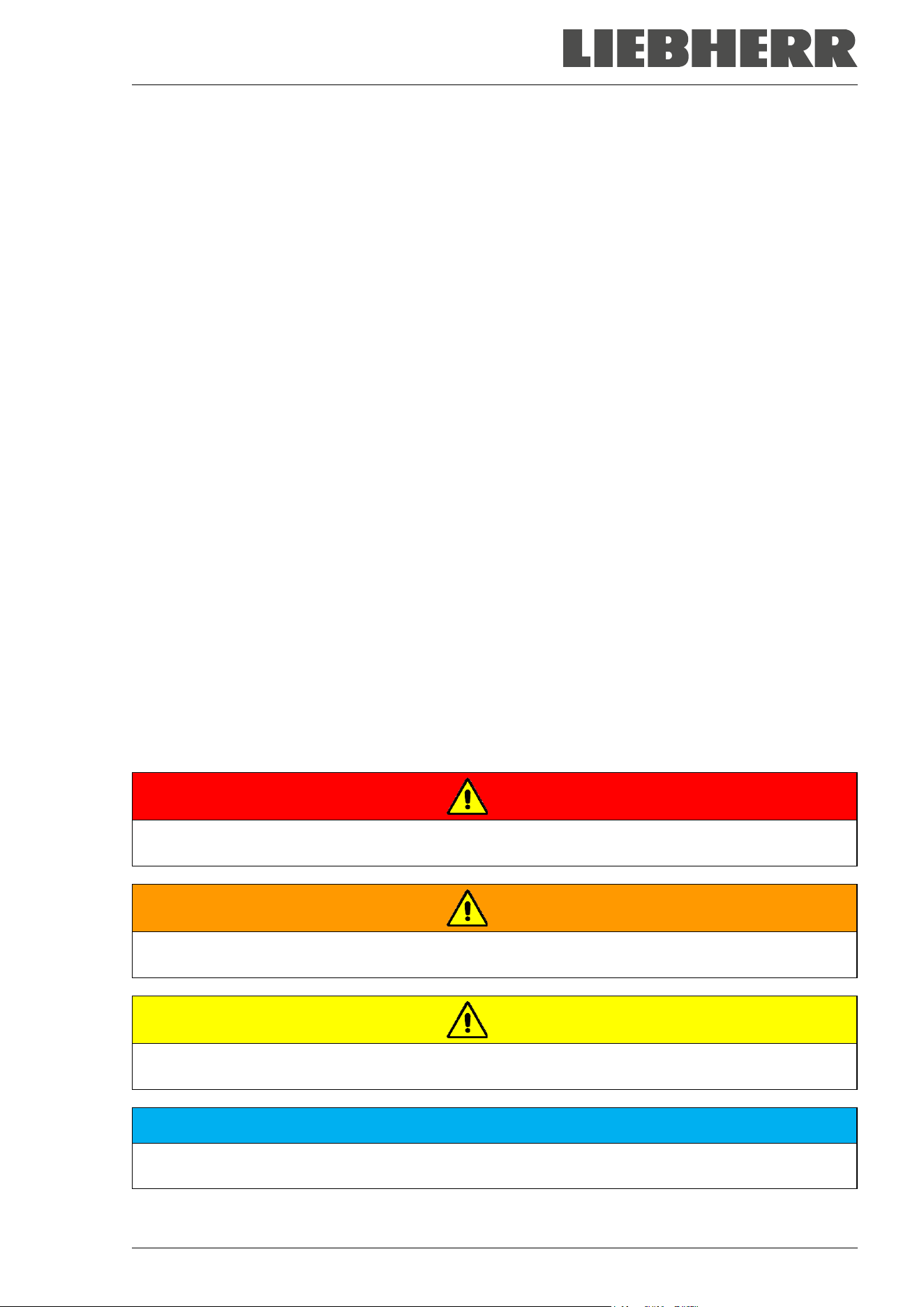
1.4.1 Signal word panel
Depending on the probability of serious consequences, potential dangers are identified with a signal word,
the corresponding safety color, and if appropriate, the safety alert symbol.
DANGER
Indicates an imminently hazardous situation that, if not avoided, will result in death or serious (irreversi-
ble) injury.
WARNING
Indicates a potentially hazardous situation which, if not avoided, could result in death or serious
(irreversible) injury
CAUTION
Indicates a potentially hazardous situation which, if not avoided, may result in moderate or minor
(reversible) injury
NOTICE
Indicates a potentially hazardous situation which, if not avoided, may result in damage to the product
and/or its functions or of a property in its proximity.
SUFsg 12/2024 Page 8/112
1.4.2 Safety alert symbol
Use of the safety alert symbol indicates a risk of injury.
Observe all measures that are marked with the safety alert symbol in order to avoid death or
injury.
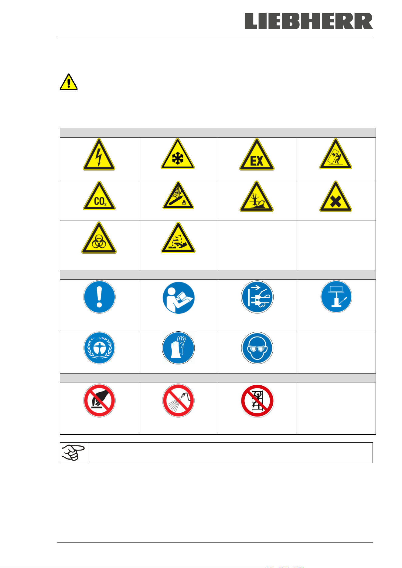
1.4.3 Pictograms
Warning signs
Electrical hazard
Very cold surface
Explosive atmosphere
Stability hazard
CO
2
suffocation hazard
Gas cylinders
Pollution Hazard
Harmful substances
Biohazard
Risk of corrosion and /
or chemical burns
Mandatory action signs
Mandatory regulation
Read operating
instructions
Disconnect the power
plug
Lift with mechanical
assistance
Environment protection
Wear protective gloves
Wear safety goggles
Prohibition signs
Do NOT touch
Do NOT spray with
water
Do NOT climb
Information to be observed in order to ensure optimum function of the product.
SUFsg 12/2024 Page 9/112
1.4.4 Word message panel structure
Type / cause of hazard.
Possible consequences.
∅ Instruction on how to avoid the hazard: prohibition
Instruction on how to avoid the hazard: mandatory action
Observe all other notes and information not necessarily emphasized in the same way, in order to avoid
disruptions that could result in direct or indirect injury or property damage.
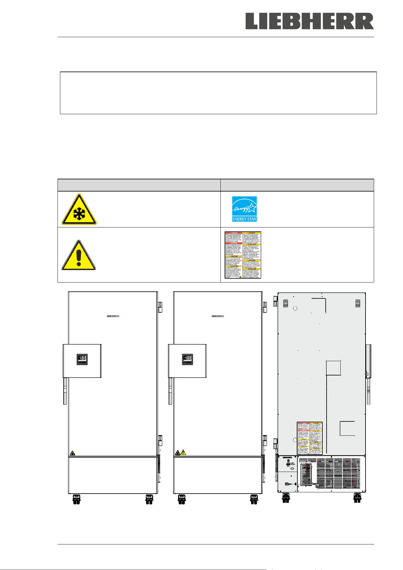
1.5 Localization / position of safety labels at the chamber
The following labels are located on the chamber:
Pictograms (Warning signs) Information
Very cold surface: Risk of freezing
Energy Star Symbol
(only SUFsg 5001 and 7001)
Risk of injury.
Observe the safety instructions in the
operating manual.
(only UL chambers and chambers
with optional CO
2
emergency cool-
ing)
Flammable refrigerants
(only SUFsg 5001,123, SUFsg
7001,123, SUFsg 3501,137,
SUFsg 5001,137, SUFsg
7001,137))
SUFsg regular chamber SUFsg with optional
CO
2
emergency cooling
SUFsg voltages 115V and
208-230 V, rear view
Figure 1: Position of labels on the ultra-low temperature freezer SUFsg
SUFsg 12/2024 Page 10/112
Keep safety labels complete and legible.
Replace safety labels that are no longer legible. Contact the manufacturer’s Service for these replacements.
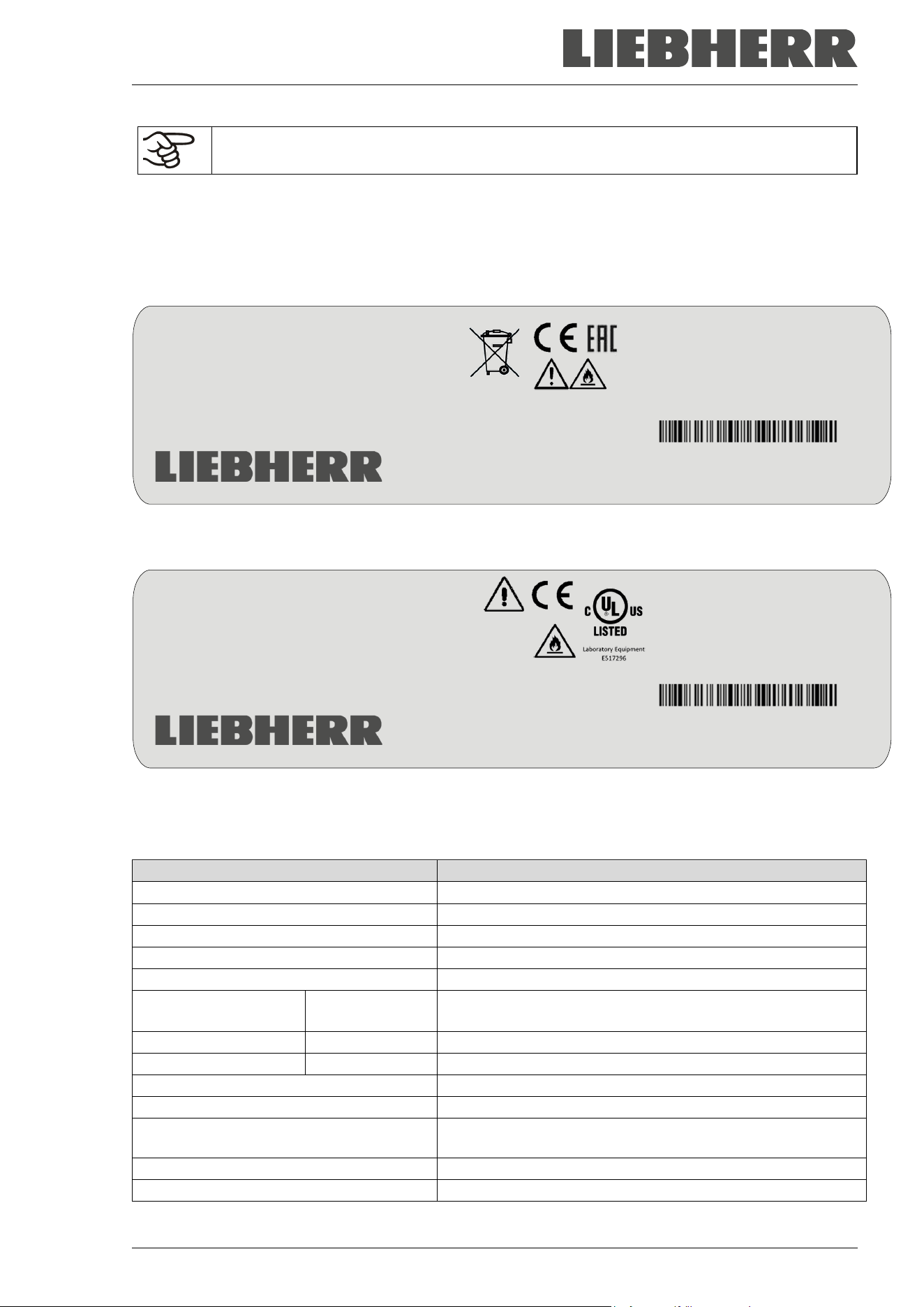
1.6 Type plate
The type plate sticks to the left side of the chamber, bottom right-hand.
Figure 2: SUFg type plate (example SUFsg 5001,001)
Figure 3: SUFg type plate (example SUFsg 5001,137)
Indications of the type plate (example):
Indication
Information
LIEBHERR
Distributor: Liebherr Hausgeräte GmbH
SUFsg 5001-70B 001
Model designation
Ultra Low Temperature Freezer
Chamber name
Serial No. 69.000.001.4
Serial no. of the chamber
Service No. 993356901
Service no. of the chamber
Nominal temp.
-90 °C
-130 °F
Nominal temperature
Ambient temp.
+16 °C - +32 °C
Permissible ambient temperature during operation
IP protection
20
IP type of protection acc. to standard EN 60529
1,60 kW
Nominal power
7,0 A
Nominal current
230 V / 50 Hz
Nominal voltage +/- 10%
at the indicated power frequency
Phase 1 N ~
Current type
Gross volume: 500 liter
Volume of the chamber interior
Nominal temp.
-90 °C
1,60 kW / 7,0 A
Gross volume: 491 liter
-130 °F
230 V / 50 Hz
Max. operating pressure 28 bar
Ambient temp.
+16 °C - +32 °C
Contains hydrocarbon gases
IP protection
20
Ultra-Tiefkühlschrank
Phase
1 N ~
107
Congélateur à ultra-basse temp
Ultra Low Temperature Freezer
Низкотемпературный морозильник
Stage 1: R290
Stage 2: R170
0,15 kg
0,15 kg
SUFsg 5001-70B 001
Liebherr Hausgeräte GmbH
Memminger Straße 77-79
D-88416 Ochsenhausen
Service No.
993356902
Serial No. 69.000.001.4
Made in Germany / Сделано в Германии
Nominal temp.
-90 °C
1,80 kW / 11,7 A
Gross volume: 491 liter
-130 °F
115 V / 60 Hz
Max. operating pressure 28 bar
Ambient temp.
+16 °C - +32 °C
Contains hydrocarbon gases
IP protection
20
Ultra-Tiefkühlschrank
Phase
1 N ~
107
Congélateur à ultra-basse temp
Ultra Low Temperature Freezer
Низкотемпературный морозильник
Stage 1: R290
Stage 2: R170
0,15 kg
0,15 kg
SUFsg 5001-70B 137
Liebherr Hausgeräte GmbH
Memminger Straße 77-79
D-88416 Ochsenhausen
Service No.
090433602
Serial No. 69.000.001.4
Made in Germany / Сделано в Германии
SUFsg 12/2024 Page 11/112
Indication
Information
Max. operating pressure 28 bar
Max operating pressure in the refrigerating system
Contains hydrocarbon gases
Contains hydrocarbon gases
Stage 1: R290 – 0,15 kg
Cooling 1
st
stage: Refrigerant type, filling weight
Stage 2: R170 – 0,15 kg
Cooling 2
nd
stage: Refrigerant type, filling weight
Symbols on the type plate:
Symbol Applies to Information
All models CE conformity marking
All models except
SUFsg 3501,137
SUFsg 5001,137
SUFsg 7001,137
Electrical and electronic equipment manufactured / placed on the
market in the EU after 13 August 2005 and to be disposed of in a
separate collection according to directive 2012/19/EU on waste
electrical and electronic equipment (WEEE).
SUFsg 5001,001
SUFsg 7001,001
SUFsg 5001,H72
SUFsg 7001,H72
Not valid for SUFsg
3501
The chamber is certified according to Customs Union Technical
Regulation (CU TR) for the Eurasian Economic Union (Russia,
Belarus, Armenia, Kazakhstan Kyrgyzstan).
SUFsg 3501,137
SUFsg 5001,137
SUFsg 7001,137
The chamber is certified by Underwriters Laboratories Inc.
®
ac-
cording to the following standards:
• UL 61010-1, 3
rd
Edition, 2012-05, Rev. 2018-11
• CAN/CSA-C22.2 No. 61010-1-12, 3
rd
Edition,
Amendment 1:2018, 2012-05, Rev. 2018-11
• IEC 61010-2-011:2019
• UL 61010-2-011 (IEC 61010-2-011:2016)
SUFsg 3501,137
SUFsg 5001,137
SUFsg 7001,137
Observe the safety instructions in the operating manual
1.7 General safety instructions on installing and operating the chamber
With regard to operating the chamber and to the installation location, please observe the local and national
regulations relevant to your country.
The manufacturer is only responsible for the safety features of the chamber provided skilled electricians or
qualified personnel authorized by the manufacturer perform all maintenance and repair, and if components
relating to chamber safety are replaced in the event of failure with original spare parts.
To operate the chamber, use only original accessories from the manufacturer or accessories from third-
party suppliers authorized by the manufacturer. The user is responsible for any risk caused by using unau-
thorized accessories.
SUFsg 12/2024 Page 12/112
NOTICE
Danger of overheating due to lack of ventilation.
Damage to the chamber.
∅ Do NOT install the chamber in unventilated recesses.
Ensure sufficient ventilation for dispersal of the heat.
Observe the prescribed minimum distances when installing the chamber (chap. 3.4)
NOTICE
Danger to the environment by leakage of refrigerant in the event of a chamber de-
fect.
Alteration of the environment.
Ensure sufficient ventilation of the installation site.
Do not install or operate the chamber in hazardous locations.
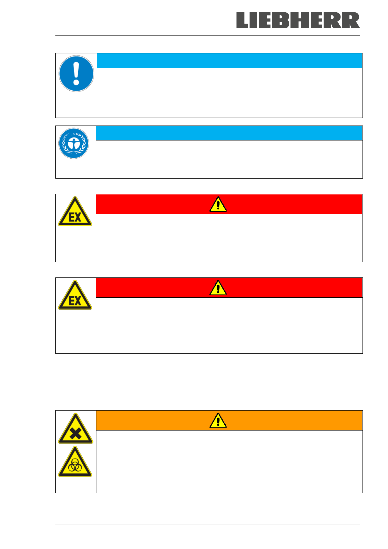
DANGER
Danger of explosion due to combustible dusts or explosive mixtures in the vicinity
of the chamber.
Serious injury or death from burns and / or explosion pressure.
∅ Do NOT operate the chamber in potentially explosive areas.
KEEP combustible dust or air-solvent mixtures AWAY from the chamber.
The chamber does not dispose of any measures of explosion protection.
DANGER
Danger of explosion due to introduction of flammable or explosive substances in
the chamber.
Serious injury or death from burns and / or explosion pressure.
∅ Do NOT introduce any substance into the chamber which is combustible or explosive at
working temperature.
∅ Do NOT introduce any combustible dust or air-solvent mixture in the inner chamber.
Any solvent contained in the charging material must not be explosive or inflammable. I.e., irrespective of
the solvent concentration in the steam room, NO explosive mixture with air must form. The temperature
inside the chamber must lie below the flash point or below the sublimation point of the charging material.
Familiarize yourself with the physical and chemical properties of the charging material.
Familiarize yourself with any potential health risks caused by the charging material. Take adequate
measures to exclude any risk prior to putting the chamber into operation.
WARNING
Danger of intoxication and infection through contamination of the chamber with
toxic, infectious or radioactive substances.
Damages to health.
Protect the interior of the chamber against contamination by toxic, infectious or radioac-
tive substances.
Take appropriate measures when bringing in or taking out toxic, infectious or radioac-
tive substances.
SUFsg 12/2024 Page 13/112
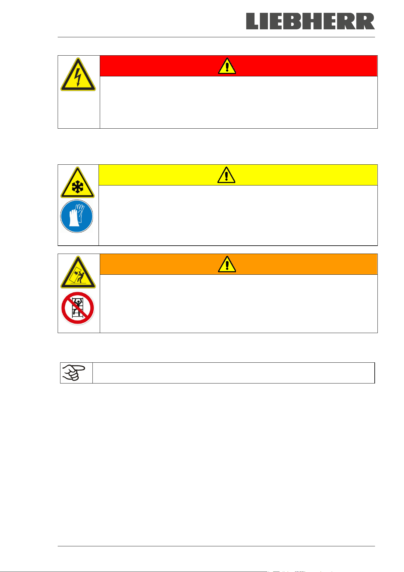
DANGER
Electrical hazard by water entering the chamber.
Deadly electric shock.
∅ The chamber must NOT become wet during operation, cleaning, or maintenance.
∅ Do NOT install the chamber in damp areas or in puddles.
Set up the chamber in a splash-proof manner.
The chambers were produced in accordance with VDE regulations and were routinely tested in accordance
to VDE 0411-1 (IEC 61010-1).
The inner surfaces become very cold during operation.
CAUTION
Danger of injury by freezing on when touching cold chamber parts during or after
operation.
Local frostbite.
∅ Do NOT directly touch the inner surfaces or the charging material during operation.
∅ AVOID skin contact with the inner surfaces and accessory equipment.
Wear protective gloves when opening the inner doors and during manipulation.
WARNING
Danger of injury and damages by the chamber tipping over or breakaway of the pro-
truding lower housing cover.
Injuries and damage to the chamber and the charging material
∅ Do NOT climb on the lower housing cover.
∅ Do NOT load the lower housing cover with heavy objects while the chamber door is
open.
1.8 Intended use
Following the instructions in this operating manual and conducting regular maintenance
work (chap. 24) are part of the intended use.
Any use of the chambers that does not comply with the requirements specified in this Operating
Manual shall be considered improper use.
Other applications than those described in this chapter are not approved.
Use
SUFsg ultra-low temperature freezers are technical equipment and intended solely for use at work. They
are suitable are designed for safe storage of varied materials at temperatures up to –90 °C / -130 °F,
especially for long-term storage of biological, medical, and chemical samples at constant low temperature.
They are suitable for the domains Pharmacy, Medicine, Life Sciences, plastic industry, electronic compo-
nents, food etc.
Freezers are designed for storage of harmless materials.
In case of foreseeable use of the chamber there is no risk for the user through the integration of the chamber
into systems or by special environmental or operating conditions in the sense of EN 61010-1. For this, the
intended use of the chamber and all its connections must be observed.
SUFsg 12/2024 Page 14/112
Requirements for the chamber load
The charging material shall not contain any corrosive ingredients that may damage the machine compo-
nents made of stainless steel. Such ingredients include in particular acids and halides. Any corrosive dam-
age caused by such ingredients is excluded from liability by the manufacturer.
None of the components of the charging material must be able to form an explosive mixture with air. Any
component of the charging material must NOT be able to release toxic gases.
The chamber does not dispose of any measures of explosion protection.
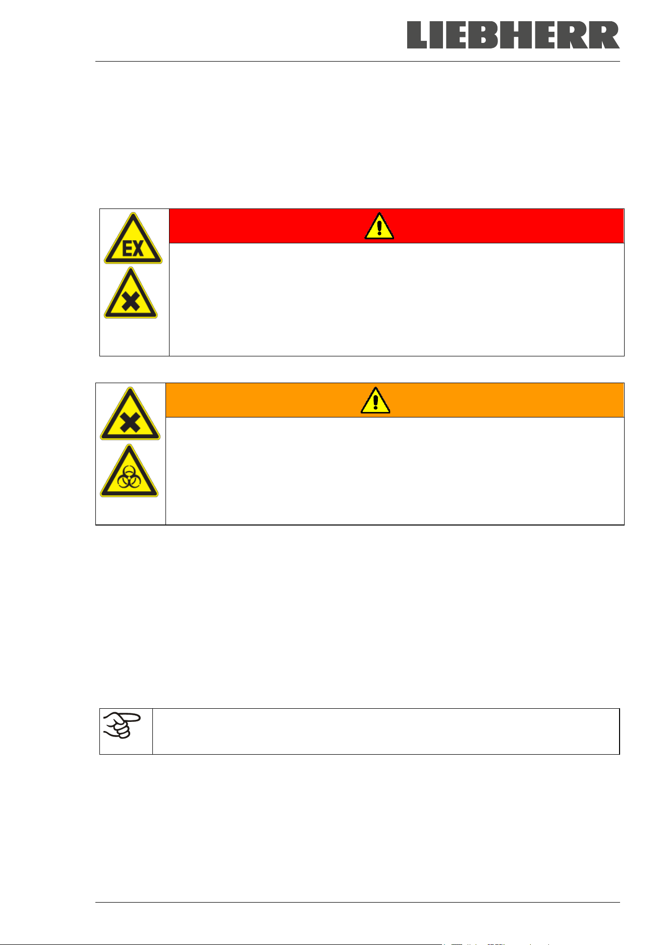
DANGER
Explosion or implosion hazard and danger of poisoning through the introduction of
unsuitable loading material.
Poisoning. Serious injury or death from burns and / or explosion pressure.
∅ Do NOT introduce any substance combustible or explosive into the chamber, in partic-
ular no energy sources such as batteries or lithium-ion batteries.
∅ NO explosive dust or air-solvent mixture in the inner chamber.
∅ Do NOT introduce any substance which could lead to release of toxic gases.
Contamination of the chamber by toxic, infectious or radioactive substances must be prevented
WARNING
Danger of intoxication and infection through contamination of the chamber with
toxic, infectious or radioactive substances.
Damages to health.
Protect the interior of the chamber against contamination by toxic, infectious or radioac-
tive substances.
Take appropriate measures when bringing in or taking out toxic, infectious or radioac-
tive substances.
Medical devices
The chambers are not classified as medical devices as defined by Regulation (EU) No 2017/745.
Personnel Requirements
Only trained personnel with knowledge of the Operating Manual can set up and install the chamber, start it
up, operate, clean, and take it out of operation. Service and repairs call for further technical requirements
(e.g. electrical know-how), as well as knowledge of the service manual.
Installation site requirements
The chambers are designed for setting up inside a building (indoor use).
The requirements described in the Operating Manual for installation site and ambient conditions (Chap.
3.4) must be met.
WARNING: If customer should use a chamber running in non-supervised continuous opera-
tion, we strongly recommend in case of inclusion of irrecoverable specimen or samples to
split such specimen or samples and store them in at least two chambers, if this is feasible.

SUFsg 12/2024 Page 15/112
1.9 Foreseeable Misuse
Other applications than those described in chap. 1.8 are not approved.
This expressly includes the following misuses (the list is not exhaustive), which pose risks despite the in-
herently safe construction and existing technical safety equipment:
• Non-observance of Operating Manual
• Non-observance of information and warnings on the chamber (e.g. control unit messages, safety iden-
tifiers, warning signals)
• Installation, startup, operation, maintenance and repair by untrained, insufficiently qualified, or unau-
thorized personnel
• Missed or delayed maintenance and testing
• Non-observance of traces of wear and tear
• Insertion of materials excluded or not permitted by this Operating Manual.
• Non-compliance with the admissible parameters for processing or storing the respective material.
• Installation, testing, service or repair in the presence of solvents
• Installation of replacement parts and use of accessories and operating resources not specified and au-
thorized by the manufacturer
• Bypassing or changing protective systems, operation of the chamber without the designated protective
systems
• Non-observance of messages regarding cleaning and disinfection of the chamber.
• Spilling water or cleaning agent on the chamber, water penetrating into the chamber during operation,
cleaning or maintenance.
• Cleaning activity while the chamber is turned on.
• Operation of the chamber with a damaged housing or damaged power cord
• Continued operation of the chamber during an obvious malfunction
• Insertion of objects, particularly metallic objects, in louvers or other openings or slots on the chamber
• Human error (e.g. insufficient experience, qualification, stress, exhaustion, laziness)
To prevent these and other risks from incorrect operation, it is recommended to issue operating instructions
and Standard operating procedures (SOPs).
1.10 Residual Risks
The unavoidable design features of a chamber, as well as its proper field of application, can also pose risks,
even during correct operation. These residual risks include hazards which, despite the inherently safe de-
sign, existing technical protective equipment, safety precautions and supplementary protective measures,
cannot be ruled out.
Messages on the chamber and in the Operating Manual warn of residual risks. The consequences of these
residual risks and the measures required to prevent them are listed in the Operating Manual. Moreover, the
operator must take measures to minimize hazards from unavoidable residual risks. This includes, in partic-
ular, issuing operating instructions.
The following list summarizes the hazards against which this Operating Manual and the Service Manual
warn, and specifies protective measures at the appropriate spots:

SUFsg 12/2024 Page 16/112
Unpacking, Transport, Installation
• Sliding or tilting the chamber
• Setup of the chamber in unauthorized areas
• Installation of a damaged chamber
• Installation of a chamber with damaged power cord
• Inappropriate site of installation
• Missing protective conductor connection
Normal operation
• Assembly errors
• Contact with cold surfaces on the housing and on the inside of the door
• Emission of non-ionizing radiation from electrical operating resources
• Contact with live parts in normal state
Cleaning and Decontamination
• Penetration of water into the chamber
• Inappropriate cleaning and decontamination agents
• Enclosure of persons in the interior
Malfunction and Damage
• Continued operation of the chamber during an obvious malfunction or outage of the cooling system
• Contact with live parts during error status
Operation of a unit with damaged power cord
Maintenance
• Maintenance work on live parts.
• Execution of maintenance work by untrained/insufficiently qualified personnel
• Electrical safety analysis during annual maintenance not performed
Trouble-shooting and Repairs
• Non-observance of warning messages in the Service Manual
• Trouble-shooting of live parts without specified safety measures
• Absence of a plausibility check to rule out erroneous inscription of electrical components
• Performance of repair work by untrained/insufficiently qualified personnel
• Inappropriate repairs which do not meet the quality standard specified by the manufacturer
• Use of replacement parts other than original replacement parts
• Electrical safety analysis not performed after repairs

SUFsg 12/2024 Page 17/112
1.11 Operating instructions
Depending on the application and location of the chamber, we recommend that the operator of the chamber
provides the relevant information for safe operation of the chamber in a set of operating instructions.
Keep these operating instructions with the chamber at all times in a place where they are
clearly visible. They must be comprehensible and written in the language of the employees.
1.12 Measures to prevent accidents
The operator of the chamber must observe the locally applicable guidelines for operating the chamber and
take precautions to prevent accidents
Following measures have been taken by the manufacturer in order to prevent ignition and explosions:
• Indications of the type plate
See operating manual chap. 1.6
• Operating manual
An operating manual is available for each chamber.
• Temperature monitoring
The chamber has a temperature display which can be read from outside.
An additional temperature safety device is built into the chamber. A visual and an audible signal (buzzer)
show exceeding of the temperature.
• Safety, measurement and control devices
The safety, measuring, and control devices are easily accessible.
• Electrostatic charge
The interior parts are grounded.
• Non-ionizing radiation
Non-ionizing radiation is not intentionally produced, but released only for technical reasons by electrical
equipment (e.g. electric motors, power cables or solenoids). Additionally, the machine has no strong
permanent magnets. If persons with active implants (e.g. pacemakers, defibrillators) keep a safe dis-
tance (distance of field source to implant) of 30 cm, an influence of these implants can be excluded with
high probability.
• Protection against touchable surfaces
Tested according to EN ISO 13732-3:2008.
• Floors
See operating manual chap. 3.4 for installation
• Cleaning
See operating manual chap. 23.
• Examinations
UL chambers only: The chamber is certified by Underwriters Laboratories Inc.
®
according to the stand-
ards UL 61010-1, 3
rd
Edition, 2012-05, Rev. 2018-11; CAN/CSA-C22.2 No. 61010-1-12, 3
rd
Edition,
Amendment 1:2018, 2012-05, Rev. 2018-11; IEC 61010-2-011:2019; UL 61010-2-011 (IEC 61010-2-
011:2016).

SUFsg 12/2024 Page 18/112
2. Chamber description
The SUFsg ultra-low temperature freezers were produced with great care using the latest tools for devel-
opment and production. They were optimized for safe long-term storage of samples in the ultra-low tem-
perature range. You can operate the freezer in a temperature range from -90 °C / -130 °F up to -40 °C / -
40 °F.
The freezers are available for several different voltages.
Lockable protective flap for the main power switch (option)
An additional locking system with key for the freezer’s main power switch is optionally available.
Controller and safety
The efficient chamber controller is equipped with a multitude of operating functions, in addition to recorder
and alarm functions.
Temperature setting is accurate to a tenth of a degree. The controller is mounted at the optimal height for
operation.
The controller offers an error diagnostics system generating audible and visual warning and alarm mes-
sages.
In case of a power failure, alarm function and control remain active during 72h through the battery-buffered
alarm system. The controller provides password protection for the setting menus.
The controller monitors ambient temperature and issues an alarm if it exceeds an adjustable value.
Thanks to the standard overtemperature safety device, the set temperature is maintained also in case of a
controller failure.
In case of power failure at -80 °C / -112 °F, a temperature of -60 °C / -76 °F will not be exceeded in an
empty freezer for at least 3.5 hours, in a loaded freezer (measured with a 30 kg / 66 lb water load) for
approx. 7 hours.
Housing
The inner chamber and the inside of the insulated outer door are made of stainless steel (German material
no. 1.4016, US equivalent AISI 430). The housing including all corners and edges is plastic coated. The
inner surfaces are smooth and therefore easy to clean. Easy front access permits filter cleaning without
tools. Three 28 mm access port serve to introduce a sensor cable of a measuring device, the upper left one
(6a) also to connect the optional CO
2
emergency cooling
The buildup of ice in the door area is minimal due to perfect closing of the inner and outer doors. Precise
spatial distribution of the cold in the interior ensures storage of all samples at an identical storage temper-
ature. The prevention of thermal bridges protects against defrosting. The combination of vacuum insulation
panels (VIP technology) and CFC-free polyurethane foaming maximizes the insulation capacity.
The freezer has two compartment doors. You can insert stainless steel shelves are make optimum use of
the interior. You can flexibly arrange the shelves to use the interior in a variable and optimum manner.
Inventory racks (stainless steel storage racks with cryo boxes, chap. 22) are optionally available.
Castors with locks serve to move the freezer.

SUFsg 12/2024 Page 19/112
Cooling system
The powerful, energy-efficient and low-noise refrigerating machine uses the environmentally friendly
“green” refrigerants R290 (propane) und R170 (ethane). They are completely free of HCFCs (hydrochloro-
fluorocarbons) and CFCs (chlorofluorocarbon).
Control of the two-stage refrigerating machine: The 1
st
stage cooling immediately turns on. In addition, the
2
nd
stage cooling turns on depending on the temperature.
Battery-buffered alarm system
The freezer is equipped with a rechargeable battery (12 V, 7.2 Ah). Battery voltage is regularly monitored.
An alarm indicates too low battery voltage. You can check the battery voltage in the controller menu.
An error diagnostics system monitors the chamber functions and generates audible and visual warning and
alarm messages. E.g., the door is monitored for being closed.
The CO
2
emergency cooling (option, chap. 20) offers additional refrigeration, i.e., following introduction of
a heat load, in case of a power failure or failure of the cooling system.
Data monitoring and recording
The chamber is regularly equipped with a zero-voltage relay alarm output (chap. 14.4.7) and optionally with
an analog output (chap. 21.2) for integration into customer systems.
The freezer is regularly equipped with an Ethernet interface (chap. 21.1) for computer communication,
enabling monitoring via a network.
SUFsg 12/2024 Page 20/112
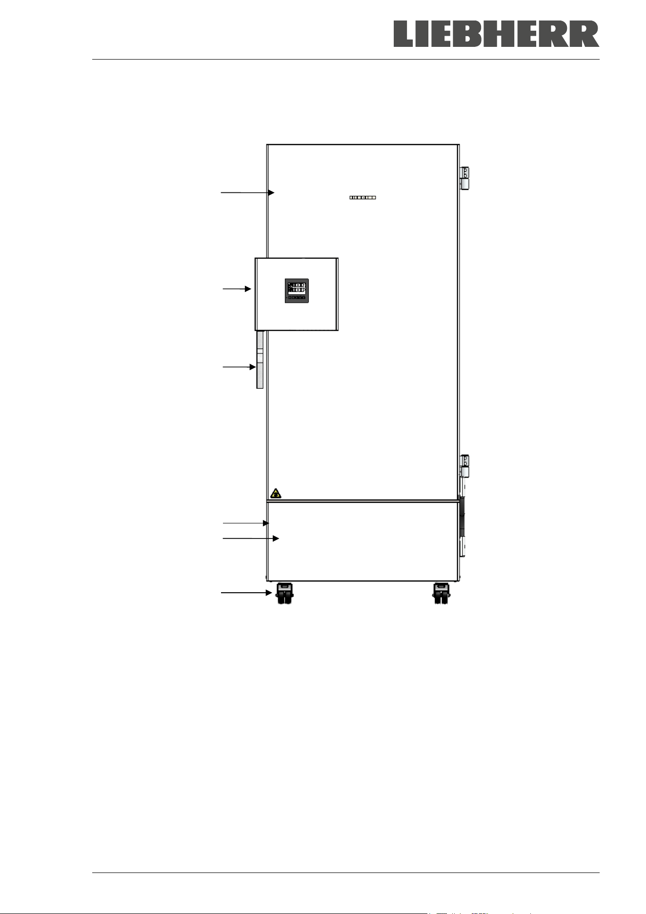
2.1 Chamber overview
(A)
(B)
(C)
(D)
(E)
(F)
Figure 4: Ultra-low temperature freezer SUFsg (example SUFsg 7001), front view
(A) Outer door
(B) Door lock and controller housing (description chap. 2.2)
(C) Door handle
(D) Compressor housing
(E) Cover flap (checking and cleaning / replacing the filter chap. 24.2.1)
(F) Castors (front castors lockable by breaks)
SUFsg 12/2024 Page 21/112
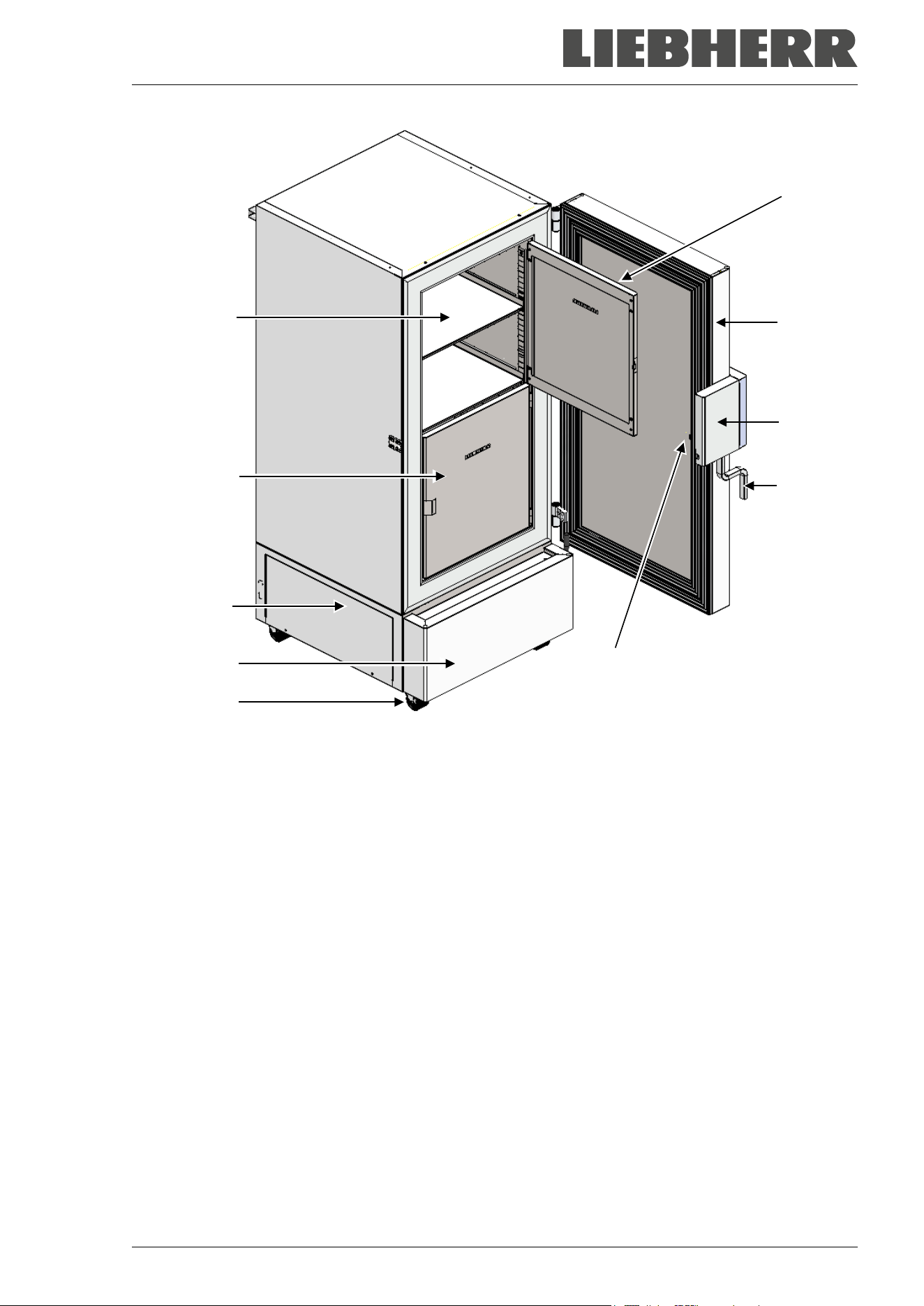
Figure 5: Ultra-low temperature freezer SUFsg 7001, open
(A) Outer door
(B) Door lock and controller housing (description chap. 2.2)
(C) Door handle
(D) Compressor housing
(E) Cover flap (checking and cleaning / replacing the filter chap. 24.2.1)
(F) Castors (front castors lockable by breaks)
(G) Compartment with variable shelf
(H) Compartment door
(I) Pressure compensation valve (inside of the door behind the door lock and controller housing)
(H)
(A)
(B)
(C)
(G)
(H)
(D)
(E)
(F)
(I)
SUFsg 12/2024 Page 22/112
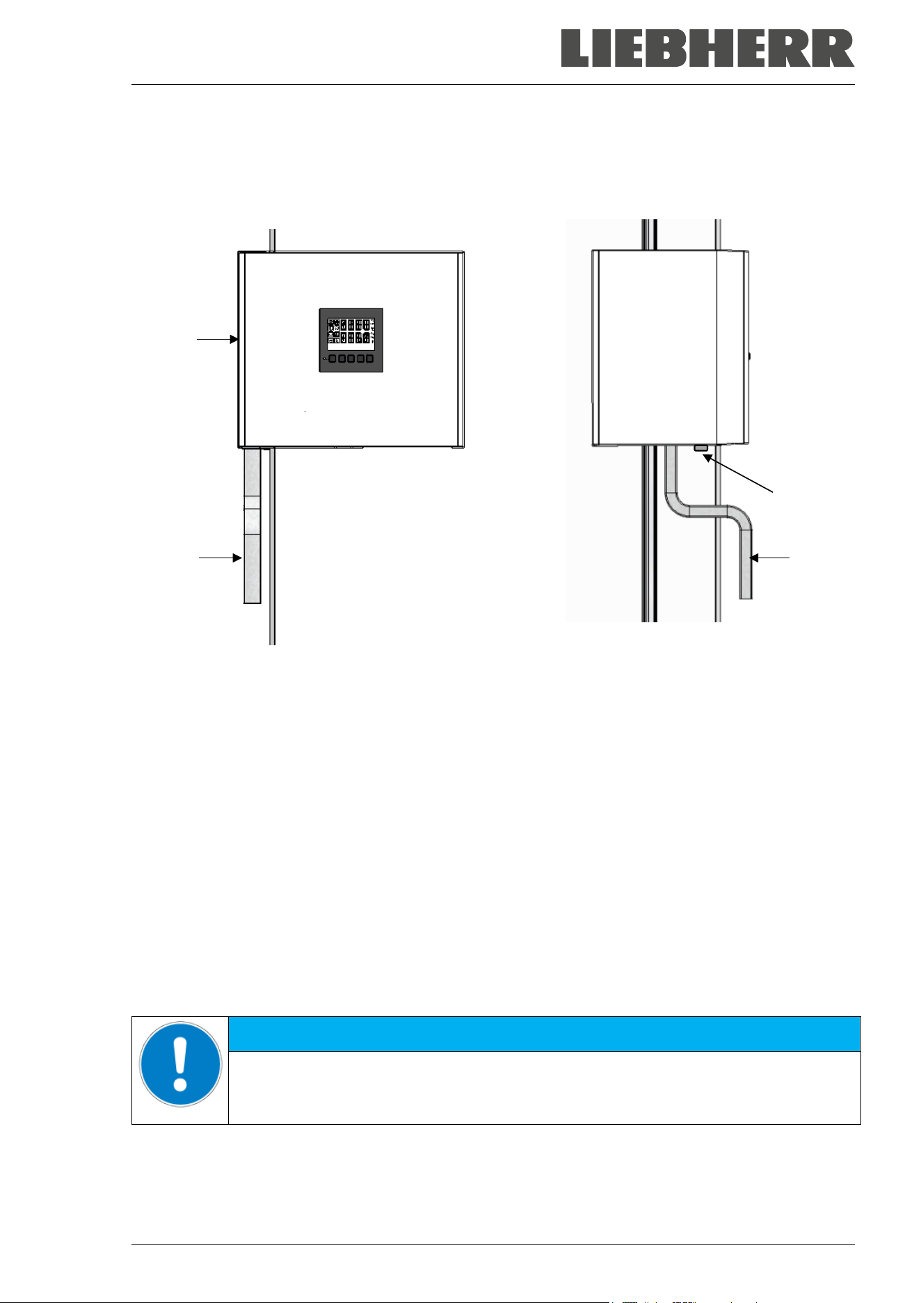
2.2 Door lock and controller housing
The controller operator panel is integrated in the freezer‘s door lock and controller housing (B).
A door handle (C) serves to open and close the chamber door.
Front view Left chamber side
Figure 6: Door lock and controller housing with controller operator panel and door handle
(B) Door lock and controller housing
(C) Door handle
(18) Door lock
2.2.1 Operating the door lock
The door lock (18) is located on the left side of the chamber in front of the door handle. Two keys are
included. To lock the door lock, turn the key clockwise. The key can be removed in both positions (open /
locked).
Note: Be sure to remove the key before opening the door. Otherwise the door lock may be damaged.
NOTICE
Danger of damage when opening the door with the key inserted.
Damage to the door lock.
Remove the key before opening the door with the door handle.
(C)
(C)
(B)
(18)
SUFsg 12/2024 Page 23/112
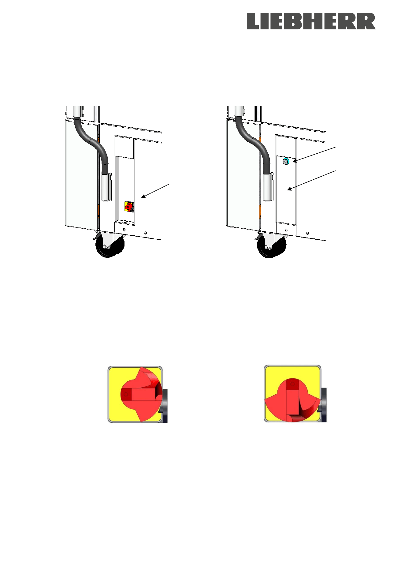
2.3 Main power switch
The main power switch is located on the bottom right side of the chamber.
In addition, a lockable protective flap covering the main power switch is optionally available. It can be un-
locked with a key and then removed.
(4)
(5a)
(5)
Standard chamber Chamber with optional lockable protective flap
Figure 7: Position of the main power switch and the lockable protective flap (option) on the right side of
the chamber
(4) Main power switch
(5) Lockable protective flap (option)
(5a) Key lock of the optional lockable protective flap
Off Onn
Figure 8: Main power switch (4) on the right side of the chamber
SUFsg 12/2024 Page 24/112
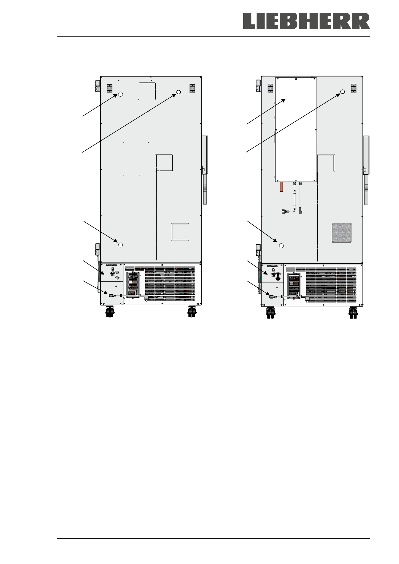
2.4 Chamber rear
(6a)
(6b)
(6c)
(I)
(7)
(J)
(6b)
(6c)
(I)
(7)
Chamber without CO
2
emergency cooling Chamber with CO
2
emergency cooling
(option)
Figure 9: Chamber rear
(6a) 28 mm access port to connect the der CO
2
emergency cooling (option) or for cable of a supple-
mentary measuring device
(6b),(6c) 28 mm access ports, e.g., for cable of a supplementary measuring device
(7) Connecting socket for IEC connector plug with strain relief
(I) Connection panel
(J) CO
2
emergency cooling (option, chap. 20)
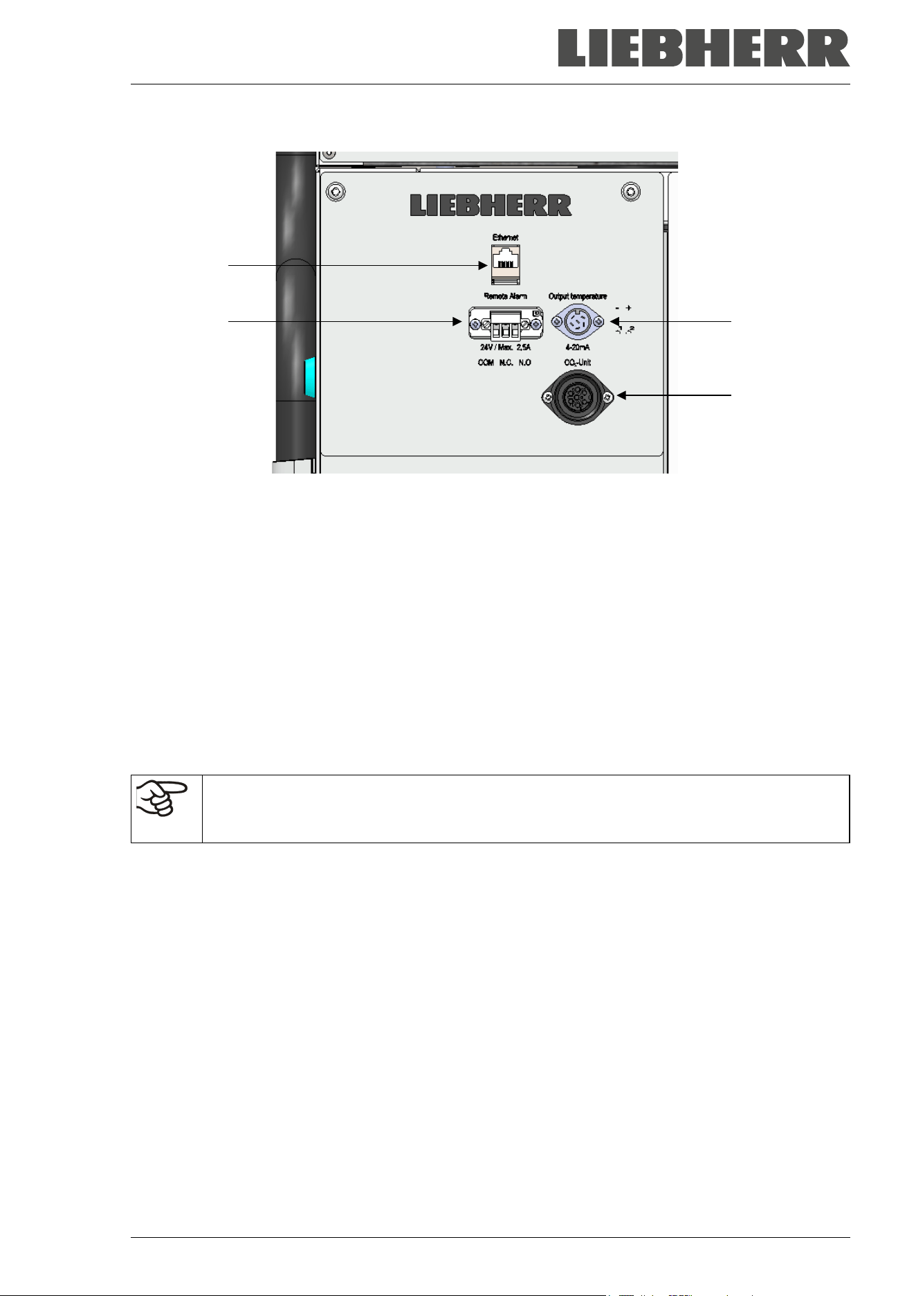
SUFsg 12/2024 Page 25/112
(8)
(9)
(10)
(11)
Figure 10: Connection panel (I) on the chamber rear, with options
(8) Ethernet interface (Chap. 21.1)
(9) Connection socket for zero-voltage relay alarm contact (chap. 14.4.7)
(10) Connection socket for analog output 4-20 mA (option, chap. 21.2)
(11) Connection socket for the electrical connection of the CO
2
emergency cooling (option, chap. 20)
2.5 Doors
2.5.1 Outer door
The outer door must be closed while the chamber is operating normally in order to ensure stable conditions
in the inner chamber.
Delay time for the door open alarm:
After closing the outer door, the door open alarm is switched off for a programmable delay
time (factory setting: 1 minute).
2.5.2 Compartment doors
The freezer interior is divided into in 4 compartments, which are isolated against the surrounding with two
doors. That permits bringing in or removing the samples of an individual compartment without remarkably
affect temperature in the other compartments.
The compartment doors remain closed by magnetism when opening the outer door without need for closing
them mechanically.
Open the inner doors as shortly as possible to avoid a temperature rise inside the freezer. The maximum
angle of aperture is 100°.
For the additional thermal insulation and sealing of the interior compartment doors, you can order the option
“compartment doors, insulated”. For this purpose, the compartment doors are filled with foam and thus
additionally thermally insulated.
SUFsg 12/2024 Page 26/112
3. Completeness of delivery, transportation, storage, and installa-
tion
3.1 Unpacking, and checking equipment and completeness of delivery
After unpacking, please check the chamber and its optional accessories, if any, based on the delivery re-
ceipt for completeness and for transportation damage. Inform the carrier immediately if transportation dam-
age has occurred.
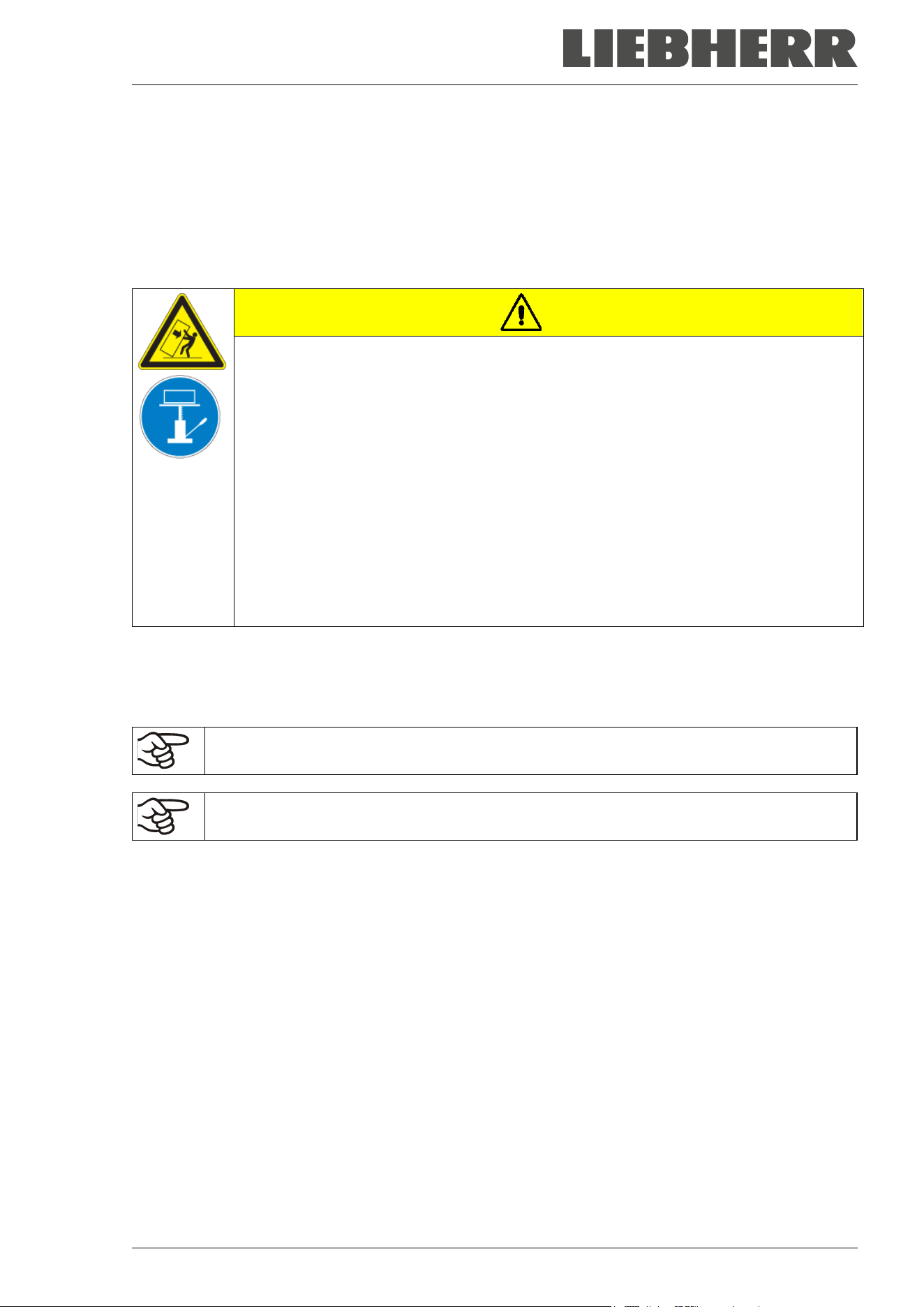
CAUTION
Risk of injury and damages by sliding or tilting of the chamber due to improper lift-
ing.
Injuries, damage to the chamber.
∅ Do NOT lift the chamber using the door, the door lock and controller housing or the
lower housing.
∅ Do NOT lift the chamber by hand.
∅ If possible, avoid transporting the chamber horizontally. It may be transported lying
down ONLY on the hinge side or on its back, but must then stand upright for at least
24 hours before turning on.
Lift the chamber using technical devices (fork lifter) from the pallet. Set the fork lifter
laterally or from the rear in the middle of the chamber. Make sure to place all the lat-
eral supports of the chamber on the forks (check: the fork protrudes at the opposite
chamber side).
Wear suitable shoes (safety shoes).
The final tests of the manufacturer may cause traces of the shelves on the inner surfaces. This has no
impact on the function and performance of the chamber.
Please remove any transportation protection devices and adhesives in/on the chamber and on the doors
and remove the operating manuals and accessory equipment.
Remove any protective lamination sheet on the inner metal surfaces prior to commissioning.
Wait at least 8 hours following transport with technical devices (chap. 3.2.2) before start-up.
If you need to return the chamber, please use the original packing and observe the guidelines for safe lifting
and transportation (chap. 3.2).
For disposal of the transport packing, see chap. 25.1.
Scope of delivery
• Ultra-low temperature freezer SUFsg
• 3 shelves and 12 shelf holders with 6 screws
• Plug for the zero-voltage relay alarm output (connected)
• Set of 2 spacers for rear wall distance.
• Operating manual (set)
• Water connection sets with chambers with water cooling
SUFsg 12/2024 Page 27/112
3.2 Guidelines for safe lifting and transportation
3.2.1 Moving the freezer inside a building
Before moving the freezer unlock the front castors. The castors are designed only for moving the freezer
inside a building. This is possible only on a floor without joints (e.g. no tiles) and when avoiding shocks. In
this case, the freezer must not be empty (max. load see technical data, chap. 26.3).
If you want to move the chamber across a large door threshold or into an elevator to change the floor,
empty the freezer and put all shelves on the bottom of the interior.
If you incline the chamber by less than 5°, you can directly turn it on after moving (at least 10 minutes after
turning off). Otherwise, wait at least 8 hours until putting it into operation again.
As soon as the chamber has reached its destination, lock the front castors.
Wear suitable shoes (safety shoes) when moving the freezer.
Over very short distances (within reach of the power cable), you can move the freezer while operating.
If you turned off the chamber (turning off at the main power switch, pulling the power plug), wait at least 10
minutes after moving until you turn on again the chamber in order to protect the refrigeration machine
against damage.
NOTICE
Risk of damage to the refrigeration system due to too quick restart of the refrigera-
tion machine after moving the chamber.
Damage to the chamber.
After moving the freezer wait 10 minutes before turning on the freezer again.
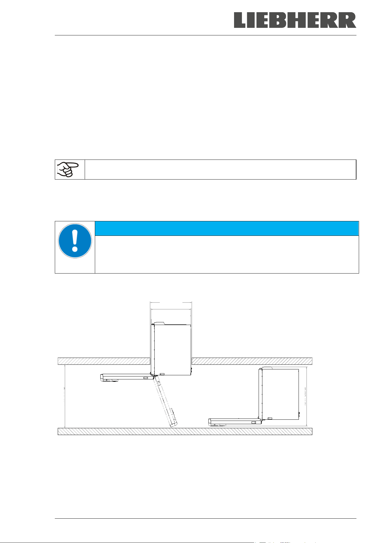
To move the freezer through narrow passages (doors, narrow corridors), open the chamber door:
Figure 11: SUFsg with open chamber door
For transport outside a building use technical equipment (chap. 3.2.2).
830 mm
900 mm
1400 mm
880 mm (SUFsg 3501)
1000 mm (SUFsg 5001
)
1280 mm (SUFsg 7001
)
SUFsg 12/2024 Page 28/112
3.2.2 Transport outside a building
Before moving the chamber unlock the front castors. The castors are designed only for moving the chamber
inside a building (respect the information given in chap. 3.2.1).
After operation, please observe the guidelines for temporarily decommissioning the chamber (chap. 25.2).
CAUTION
Risk of injury and damages by sliding or tilting of the chamber due to improper
transportation.
Injuries, damage to the chamber.
∅ Do NOT lift or transport the chamber using the door, the door lock and controller hous-
ing or the lower housing.
∅ Do NOT lift the chamber by hand
∅ If possible, avoid transporting the chamber horizontally. It may be transported lying
down ONLY on the hinge side or on its back, but must then stand upright for at least
24 hours before turning on.
Transport the chamber only in its original packaging.
Secure the chamber with transport straps for transport.
Place the shelves on top of each other on the bottom of the interior.
Lift the chamber using technical devices (fork lifter) and place it on the transport pallet.
Set the fork lifter laterally or from the rear in the middle of the chamber. Make sure to
place all the lateral supports of the chamber on the forks (check: the fork protrudes at
the opposite chamber side).
Transport chambers ONLY with the original transport pallet. Set the fork lifter only to
the pallet. Without the pallet the chamber is in imminent danger of overturning
Wear suitable shoes (safety shoes).
• Permissible ambient temperature range for transport: -20 °C / -4 °F to +60 °C / 140 °F.
You can order transport packing and rolling pallets for transportation purposes from the manufacturer.
Wear suitable shoes (safety shoes) during transport.
Following transport, wait at least 8 hours until start-up.
SUFsg 12/2024 Page 29/112
3.3 Storage
Intermediate storage of the chamber is possible in a closed and dry room. Observe the guidelines for tem-
porary decommissioning (chap. 25.2).
• Permissible ambient temperature range for storage: -20 °C / -4 °F to +60 °C / 140 °F.
• Permissible ambient humidity: max. 70% r.h., non-condensing
Secure the chamber against unintentional rolling by locking the front castors.
The freezer must stand upright in order to avoid oil running out of the engine casing and resulting damages
to the cooling system. Max. angle of inclination: 10°.
When after storage in a cold location you transfer the chamber to its warmer installation site, condensation
may form in the inner chamber or on the housing. Before start-up, wait at least one hour until the freezer
has attained ambient temperature and is completely dry. According to the type of transport that has taken
place (chap. 3.2) you may have to wait at least 8 hours until start up.
3.4 Location of installation and ambient conditions
The freezer is designed for setting up inside a building (indoor use). Set up the chamber on a flat, even
surface, free from vibration and in a well-ventilated, dry location. Lock the front castors and align the cham-
ber using a spirit level. The site of installation must be capable of supporting the chamber’s weight (see
technical data, chap. 26.3).
NOTICE
Danger of overheating due to lack of ventilation.
Damage to the chamber.
∅ Do NOT install the chamber in unventilated recesses.
Ensure sufficient ventilation for dispersal of the heat.
Make sure that all fan openings in the housing or in the construction intended for instal-
lation are uncovered.
Observe the prescribed minimum distances when installing the chamber.
NOTICE
Danger to the environment by leakage of refrigerant in the event of a chamber de-
fect.
Alteration of the environment.
Ensure sufficient ventilation of the installation site.
• Permissible ambient temperature range for operation: +16 °C / 60.8 °F to +32 °C / 89.6 °F. At elevated
ambient temperature values, fluctuations in temperature can occur.
The ambient temperature should not be substantially higher than the indicated ambient tem-
perature of +25 °C / 77 °F to which the specified technical data relate. For other ambient con-
ditions, deviations from the indicated data are possible.
Prevent the freezer from sucking warm air from other devices.
Avoid direct solar radiation on the chamber. Do not place the freezer in direct vicinity of
chambers with a high heat emission.
• Permissible ambient humidity: 70% r.h. max., non-condensing.
• Installation height: max. 2000 m / 6561.7 ft above sea level.
SUFsg 12/2024 Page 30/112
Minimum distances:
• between several chambers: 250 mm / 9.84 in
• Wall distance, rear: 100 mm / 3.94 in (spacer is supplied, see chap. 4.2)
• Wall distance, laterally, on the side without door hinge: 100 mm / 3.94 in
• Wall distance, laterally, on the side with door hinge: 240 mm / 9.45 in.
• Spacing above the chamber: 100 mm / 3.94 in
Ventilation openings must not be blocked. Ensure a distance of at least 100 mm / 3.94 in to the ventilation
openings on the freezer’s front and rear.
The freezer must stand upright in order to avoid oil running out of the engine casing and resulting damages
to the cooling system. Max. angle of inclination: 10°.
To completely separate the chamber from the power supply, you must disconnect the power
plug. Install the chamber in a way that the power plug is easily accessible and can be easily
pulled in case of danger.
With an increased amount of dust in the ambient air, clean the condenser fan (by suction or blowing) several
times a year. Check the condenser air filter frequently and clean it if necessary (chap. 24.2.1).
Avoid any conductive dust in the ambiance according to the chamber layout complying with pollution degree
2 (IEC 61010-1).
For the user there is no risk of temporary overvoltages in the sense of EN 61010-1:2010.
Do NOT install or operate the freezer in potentially explosive areas.
DANGER
Danger of explosion due to combustible dusts or explosive mixtures in the vicinity
of the chamber.
Serious injury or death from burns and / or explosion pressure.
∅ Do NOT operate the chamber in potentially explosive areas.
KEEP combustible dust or air-solvent mixtures AWAY from the chamber.
For freezers with water cooling:
To avoid any possible water damage, provide a floor drain at the location of the chamber. Se-
lect a suitable installation site to avoid any consequential damage by splashing water.
SUFsg 12/2024 Page 31/112
4. Installation and connections
4.1 Operating instructions
Depending on the application and location of the chamber, we recommend that the operator of the freezer
provides the relevant information for safe operation of the chamber in a set of operating instructions.
Keep these operating instructions with the chamber at all times in a place where they are
clearly visible. They must be comprehensible and written in the language of the employees.
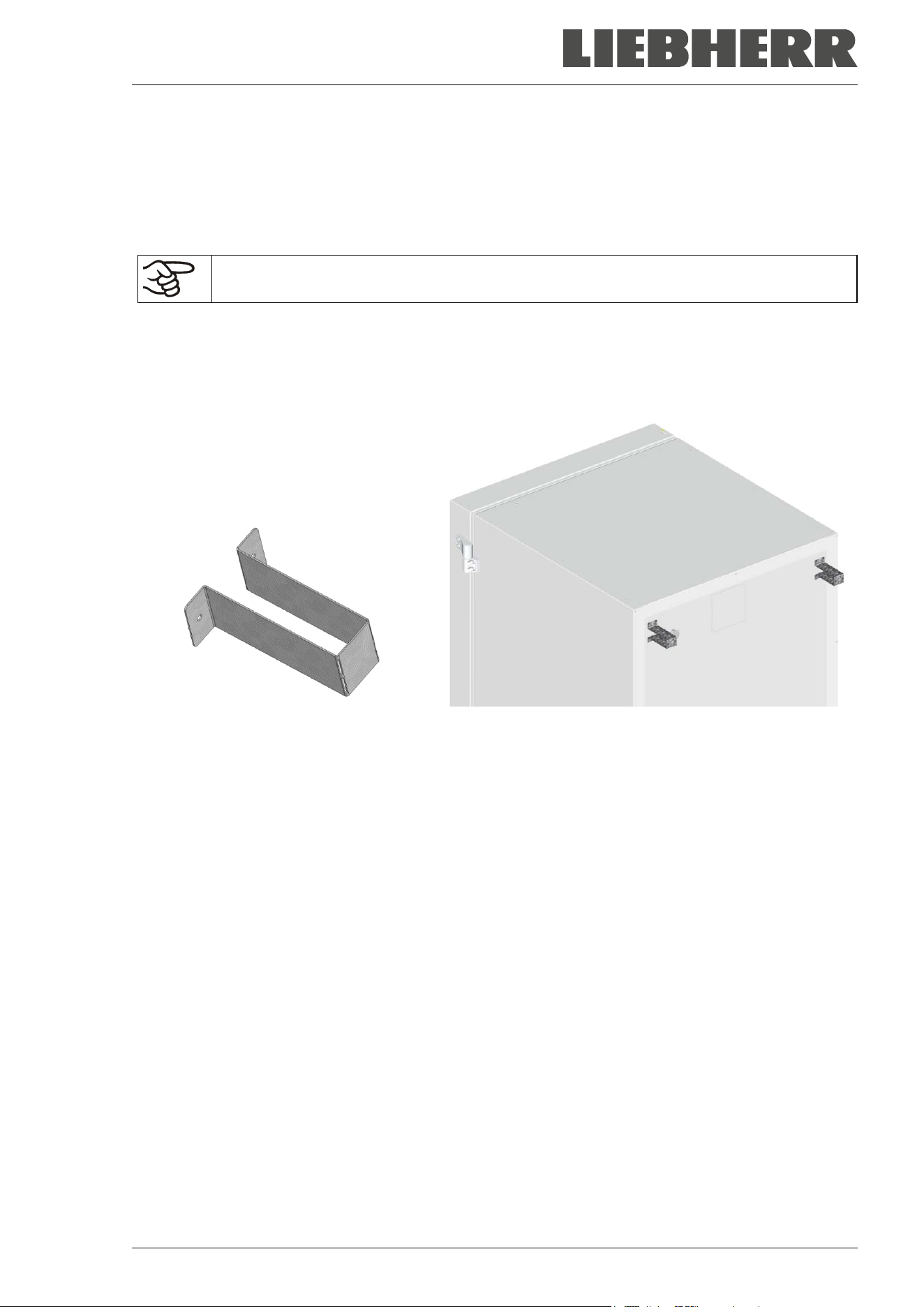
4.2 Spacers for rear wall distance
Please fix both spacers with the supplied screws at the chamber rear. This serves to ensure the prescribed
minimum distance to the rear wall of 100 mm / 3.94 in.
Figure 12: Spacer for rear wall distance Figure 13: Rear chamber with mounted spacers
4.3 Support feet (SUFsg 3501only)
To prevent tipping, it is necessary to extend the support feet on the front side under the door by turning
them down after the device has been set up
Make sure to turn up the two support feet again before moving the device.
SUFsg 12/2024 Page 32/112
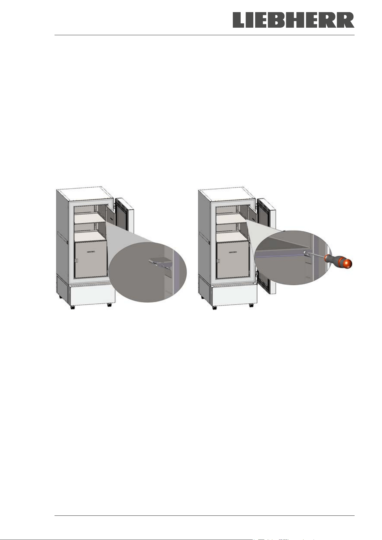
4.4 Adjustable shelves
The scope of delivery comprises three adjustable shelves. You can mount them and further optional shelves
in different positions of the lateral walls in 24 mm / 1 inch steps. In standard position, the shelves are placed
with a distance of 310mm / 12.2 in, forming the bottom of the compartments, thus making available the
maximum space for optional inventory systems.
It is required to fix the adjustable shelves in order to avoid that a person could be locked in the freezer. To
remove a shelf, remove the screws, lift and incline the shelf and then pull it forward.
Mounting the adjustable shelves:
• Insert the shelf holders at the desired height into shelf holder bars.
• Insert the shelves and screw them with a Phillips screwdriver to the shelf holders
Figure 14: Inserting the shelf holders and screwing the shelves to the shelf holders
SUFsg 12/2024 Page 33/112
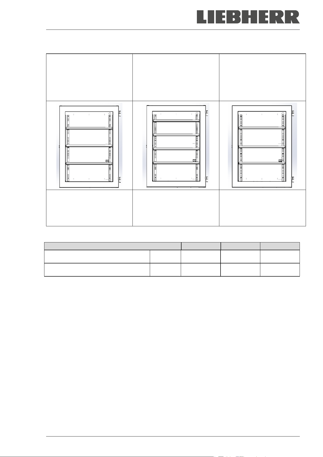
For optimal use of space, we recommend the following shelf positions:
Position of 3 shelves to obtain 4
compartments with equal ceiling
height
Position of 4 shelves (1 x op-
tional) to obtain 5 compartments
with equal ceiling height
Position of 3 shelves to obtain
the maximum sample storage
space: 2 compartments with a
ceiling height of 334 mm / 13.15
in (for racks 4x6) and 2 compart-
ments with a ceiling height of 279
mm / 11 in (for racks 4x5)
Insert the shelf holders into the
following positions of the shelf
holder bar (starting from the bot-
tom):
18, 35, 53
Insert the shelf holders into the
following positions of the shelf
holder bar (starting from the bot-
tom):
13, 29, 42, 58
Insert the shelf holders into the
following positions of the shelf
holder bar (starting from the bot-
tom):
21, 36, 53
Permitted shelf loads:
Chamber size
SUFsg 3501
SUFsg 5001
SUFsg 7001
Permitted load of individual shelf (regular) kg / lbs 40 / 88 50 / 110 50 / 110
Permitted total load of all shelves (regular) kg / lbs 160 / 353 200 / 441 200 / 441
If the upper shelf is loaded with maximum load, a minimum distance of 24 cm / 9.4 in to the ceiling of the
interior must be observed. Therefore, do not insert the shelf above position 59 (counted from bottom) of the
shelf holder bar.
SUFsg 12/2024 Page 34/112
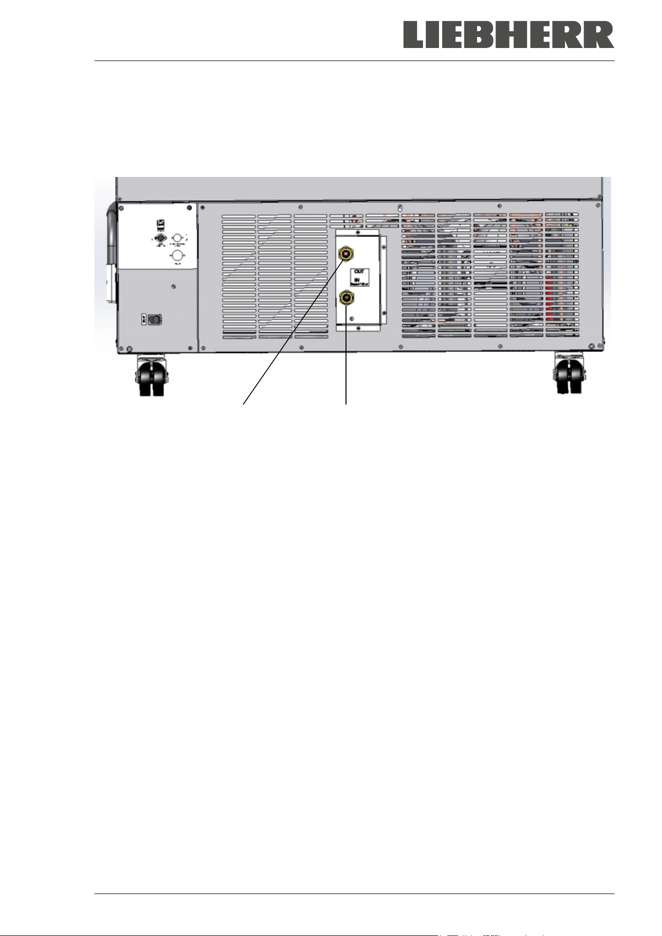
4.5 Connections of cooling water for chambers with water cooling
The water cooling reduces the heat, which is emitted during cooling operation to the ambient air.
An enclosure inside the chamber contains the connection kit for the cooling water inlet and outlet.
“OUT” “IN”
Figure 15: Connections of cooling water on the chamber rear (chambers with water cooling),
example SUFsg 7001,H72
“IN” connection for cooling water inlet with external thread 3/4‘‘ and internal thread 3/8‘‘
“OUT” connection for cooling water outlet with external thread 3/4‘‘ and internal thread 3/8‘‘
4.5.1 Connection of cooling water outlet for water cooling
Fasten the 1/2‘‘ cooling hose to the connection of cooling water outlet “OUT” on the chamber rear. Observe
the following points:
• You can use a part of the supplied water hose for the cooling water outlet. In case another hose is used,
it must be permanently resistant against max. 50 °C / 122 °F and pressure-resistant up to 10 bar.
• Put the hose on the hose nozzle with screwing and secure it with one of the four supplied hose clamps.
Connect the hose nozzle to the connection “OUT” and screw on the union nut.
• For the hose connection to the domestic water connection, we recommend to also use the supplied
hose nozzle with screwing and secure it with one of the four supplied hose clamps.
• Before turning on the chamber, check the connection for leaks.
The temperature of the effluent cooling water is 27 °C up to 29 °C on account of the chamber’s construction.
SUFsg 12/2024 Page 35/112
4.5.2 Connection of cooling water inlet for water cooling
Connect the cooling water outlet before connecting the cooling water inlet.
Requirements for the cooling water:
• Water type: cooling water, air conditioning water, tap water
• Water intake temperature: 8 °C / 46.4 °F up to 23 °C / 73.4 °F
• pH value 4 up to 8
• Water hardness of max. 142.8 mg/l (ppm) = 10 English (Clark) degrees = 8.32° grains per U.S. gallon =
1.4285 mmol/l.
• Particle size < 100 µm
• Connection pressure 1 bar up to 10 bar overpressure
• Pressure difference between inlet and outlet: at least 0,2 bar; 0,5 bar recommended. A higher pressure
difference can result in flow noise.
• The water inlet and outlet should be provided with a shut-off slide or water-tap.
• Return temperature: 27 °C up to 29 °C (pre-set on the control valve of the SUFsg)
Water demand:
• Average 10-50 l/h, depending on the intake temperature
• Short-term (duration up to 2 minutes) up to 400 l/h
The manufacturer is NOT responsible for the water quality at the user’s site.
Any problems and malfunctions that might arise following use of water of deviating quality is
excluded from liability by the manufacturer. This includes in particular a high particle content,
which may result in blockage of the water flow control valve.
The warranty becomes void in the event of use of water of deviating quality.
Fasten the 1/2‘‘cooling hose to the connection of cooling water outlet “IN” on the chamber rear. Observe
the following points:
• You can use a part of the supplied water hose for the cooling water inlet. In case another hose is used,
it must be pressure-resistant up to 10 bar.
• Put the hose on the hose nozzle with screwing and secure it with one of the four supplied hose clamps.
Connect the hose nozzle to the connection “IN” and screw on the union nut.
• For the hose connection to the domestic water connection, we recommend to also use the supplied
hose nozzle with screwing and secure it with one of the four supplied hose clamps.
• Before turning on the chamber, check the connection for leaks.
Water supply is automatically effected via the water connection “IN”.
4.5.3 Connection kit for cooling water
The ultra-low temperature freezer with water cooling comes with a connection kit. It consists of the following:
• Hose burst protection device
• 4 Hose nozzles with screwing (union nut)
• 4 hose clamps
• 6m water hose 1/2'‘, divisible for inlet and outlet, approved for max. 15 bar, max. 95 °C
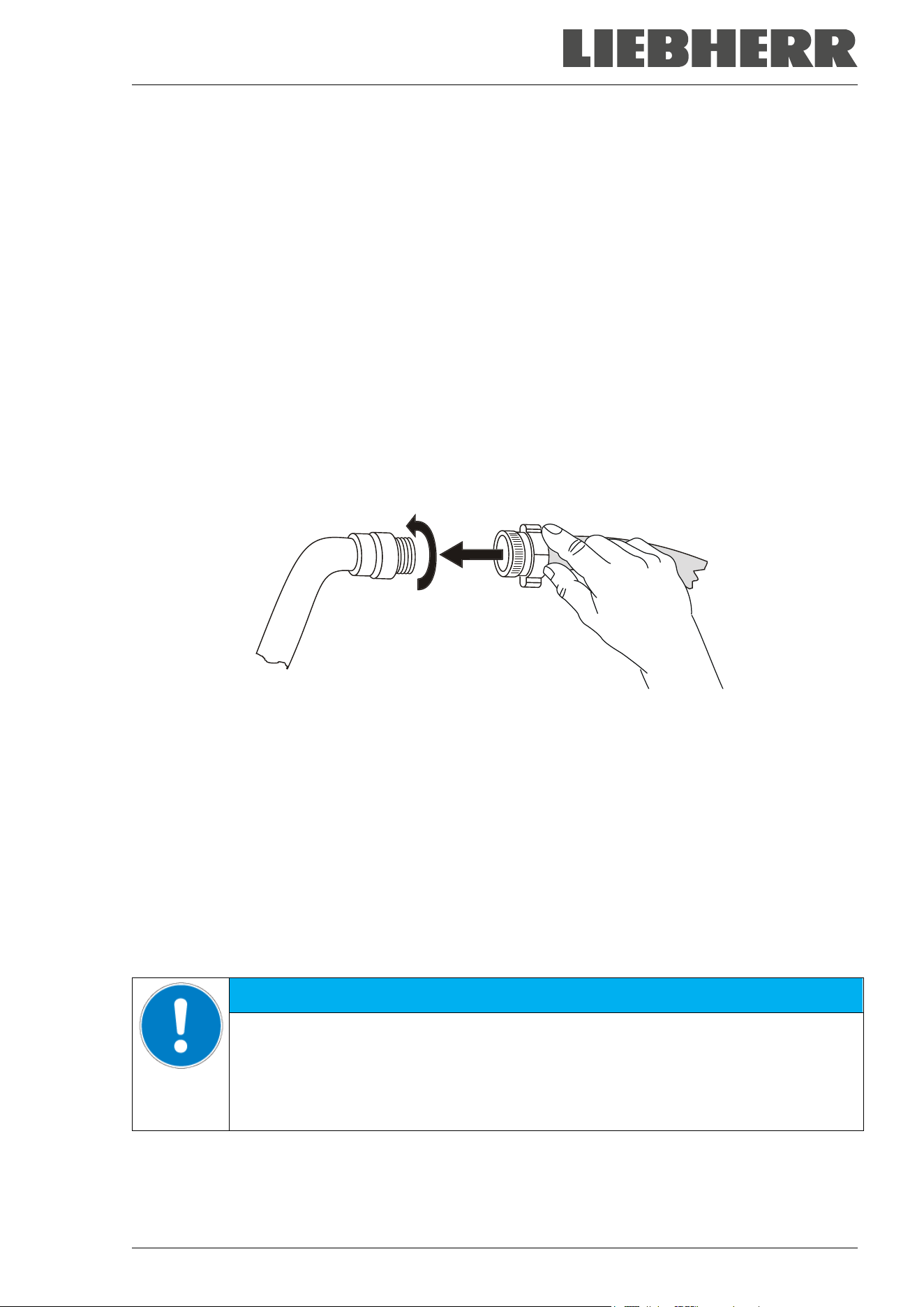
SUFsg 12/2024 Page 36/112
Protection principle of the hose burst protection
The hose burst protection device serves to protect the environment against flooding caused by burst water
hoses. It is intended for the operation of the device at a tap water line. If the freezer is operated in a cycle
of cooling water or air conditioning water, the user should check whether the hose burst protection device
provides sufficient protection. This depends mainly on a sufficient medium pressure in the system.
Whenever a strong water flow of approx. 18 l / min. occurs, e.g. caused by a burst water hose, a valve
automatically cuts off the water supply, which can be heard as a clicking noise. The water supply now
remains shut until it is manually released.
Assembly:
Screw the hose burst protection device onto a water tap with a G¾ inch right turning thread connection.
The connection is self-sealing. Establish the connection between the safety kit and the chamber with a part
of the supplied hose. Protect both ends of the hose by the supplied hose clamps.
We recommend connecting the hose as the last step in order to avoid twisting the hose while screwing on
the safety kit.
Open the water tap slowly in order to avoid actuating the hose burst protection device.
Figure 16: Assembly of the connection kit
Release of the reflux protection device:
In case the burst protection device has interrupted the water supply, first find the reason and remove it as
necessary. Close the water tap. Release the valve by a half left-turn of the upper knurled part. You can
hear the release of the valve as a clicking noise. Tighten the burst protection device against the water tap
by a right turn. Open the water tap slowly afterwards.
Maintenance of the assembly of the hose burst protection device:
Calcification can impair valve function. We recommend an annual inspection by a skilled plumber. The
plumber should remove the safety kit to check the valve by hand for proper function and calcification or
blockage.
NOTICE
Danger of impairment of the valve function due to calcification.
Damage to the chamber.
Have a plumber inspect the valve annually.
Remove calcifications by citric acid or acetic acid solutions.
Continue by testing the function and tightness of the mounted unit.
Check: Quickly open the water tap while there is no chamber connected – the valve should cut off the water
flux without any delay.
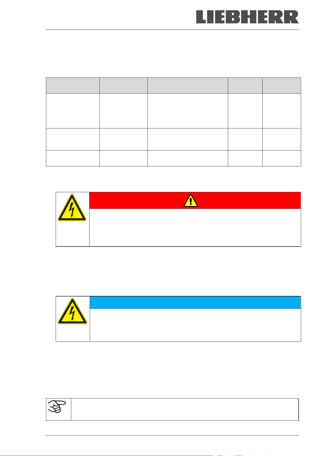
SUFsg 12/2024 Page 37/112
4.6 Electrical connection
The SUFsg ultra-low temperature freezers are supplied ready for connection and come with an IEC con-
nector plug.
An internal overload release protects the freezer against excess-current.
Model
Plug of the
power cable
Nominal voltage +/-
10% at the
indicated power frequency
Current
type
Fuse
SUFsg 3501,001
SUFsg 5001,001
SUFsg 7001,001
SUFsg 5001,H72
SUFsg 7001,H72
Grounded plug 230 V at 50 Hz 1N~ 10 A
SUFsg 3501,137
SUFsg 5001,137
SUFsg 7001,137
NEMA 5-15P 115 V at 60 Hz 1N~ 15 A
SUFsg 5001,123
SUFsg 7001,123
NEMA 6-15P 208-230 V at 60 Hz 2~ 10 A
• The domestic socket must also provide a protective conductor. Make sure that the connection of the
protective conductor of the domestic installations to the chamber’s protective conductor meets the latest
technology. The protective conductors of the socket and plug must be compatible!
DANGER
Electrical hazard due to missing protective conductor connection.
Deadly electric shock
Make sure that the chamber’s power plug and the power socket match and securely
connect the electrical protective conductors of the chamber and the house installa-
tion.
• Only use original connection cables from the manufacturer.
UL chambers: Use only a UL Listed Power supply cord (UL category ELBZ), SJT 3x14 AWG (2.08 mm²);
C13L. For outside USA use a certified power supply cord according to national requirements.
• Prior to connection and start-up, check the power supply voltage. Compare the values to the specified
data located on the chamber’s type plate (located on the left-hand side of the chamber, bottom right-
hand, chap. 1.6).
NOTICE
Danger of incorrect power supply voltage due to improper connection.
Damage to the chamber.
Check the power supply voltage before connection and start-up.
Compare the power supply voltage with the data indicated on the type plate.
• Observe a sufficient current protection according to the number of freezers that you want to operate.
We recommend the use of a residual current circuit breaker.
• When connecting, please observe the regulations specified by the local electricity supply company and
as well as the local or national electrical regulations
• Pollution degree (acc. to IEC 61010-1): 2
• Over-voltage category (acc. to IEC 61010-1): II
See also electrical data (chap. 26.3).
To completely separate the chamber from the power supply, you must disconnect the power
plug. Install the chamber in a way that the power plug is easily accessible and can be easily
pulled in case of danger.
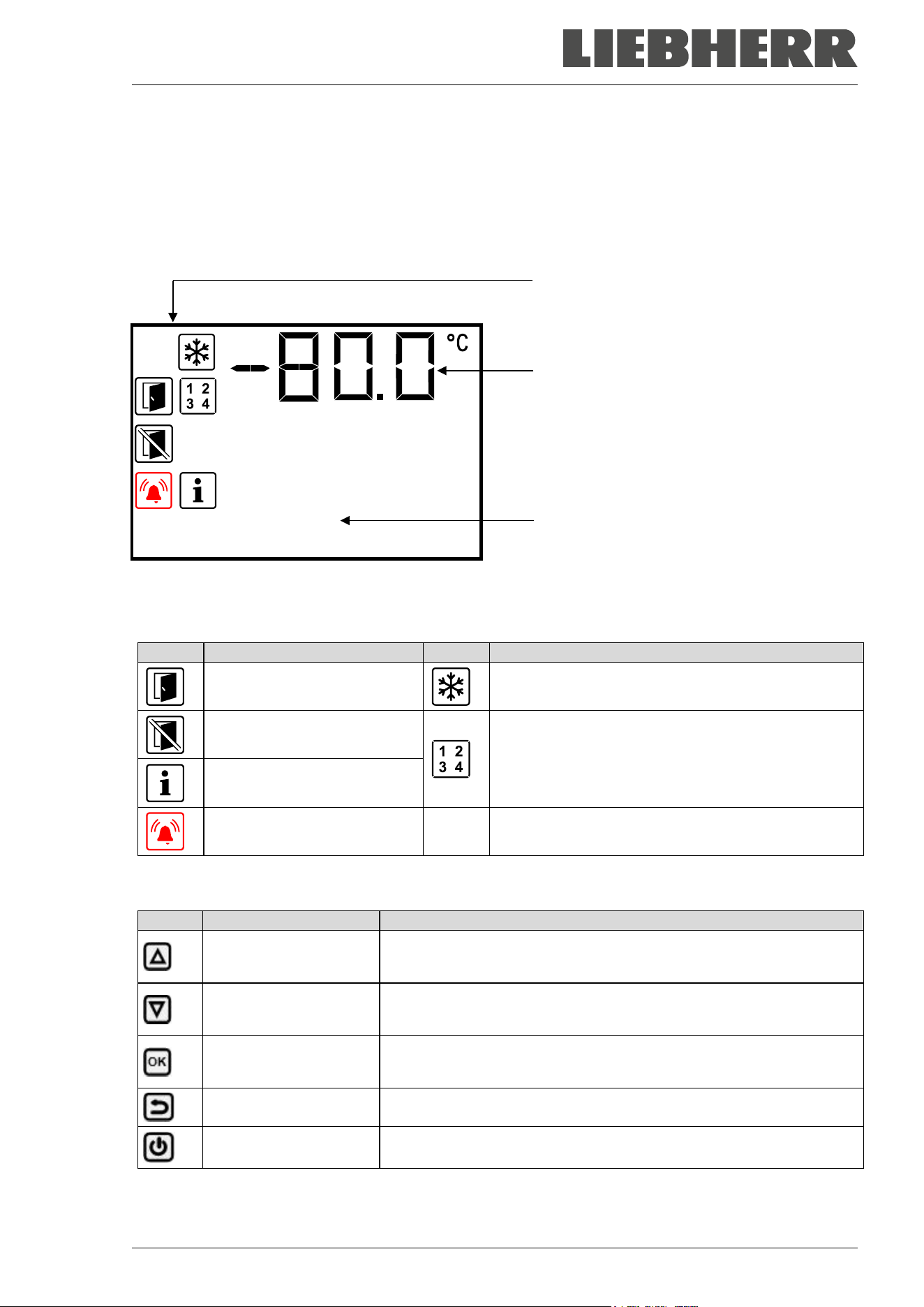
SUFsg 12/2024 Page 38/112
5. Functional overview of the chamber controller
The chamber controller controls the temperature inside the chamber:
You can enter the desired set point value in the “Set points” menu directly at the controller.
The controller offers various notifications and alarm messages with visual and audible indication. All con-
troller settings remain valid until the next manual change. They are stored also after turning off the chamber.
Status icons
Temperature value
Text information
Temperature
Figure 17: Normal display of the chamber controller (sample values)
Status icons in the controller display
Icon
Signification
Icon
Signification
Door open
Refrigeration active
Do not open the door
Display of activated special controller functions.
1 = CO
2
emergency cooling activated
2 = Emergency cooling test activated
3 = Service setpoint active
Information
Collective alarm
Functional controller keys
Icon
Signification
Function
Arrow-up button
• Navigate between menus, submenus, other functions
• In the setting menu: change setting, increase value
Arrow-down button
• Navigate between menus, submenus, other functions
• In the setting menu: change setting, decrease value
OK button
• Select menu, submenu, function
• In the setting menu: Confirm entry
Back button Back to previous menu level
Standby button no function
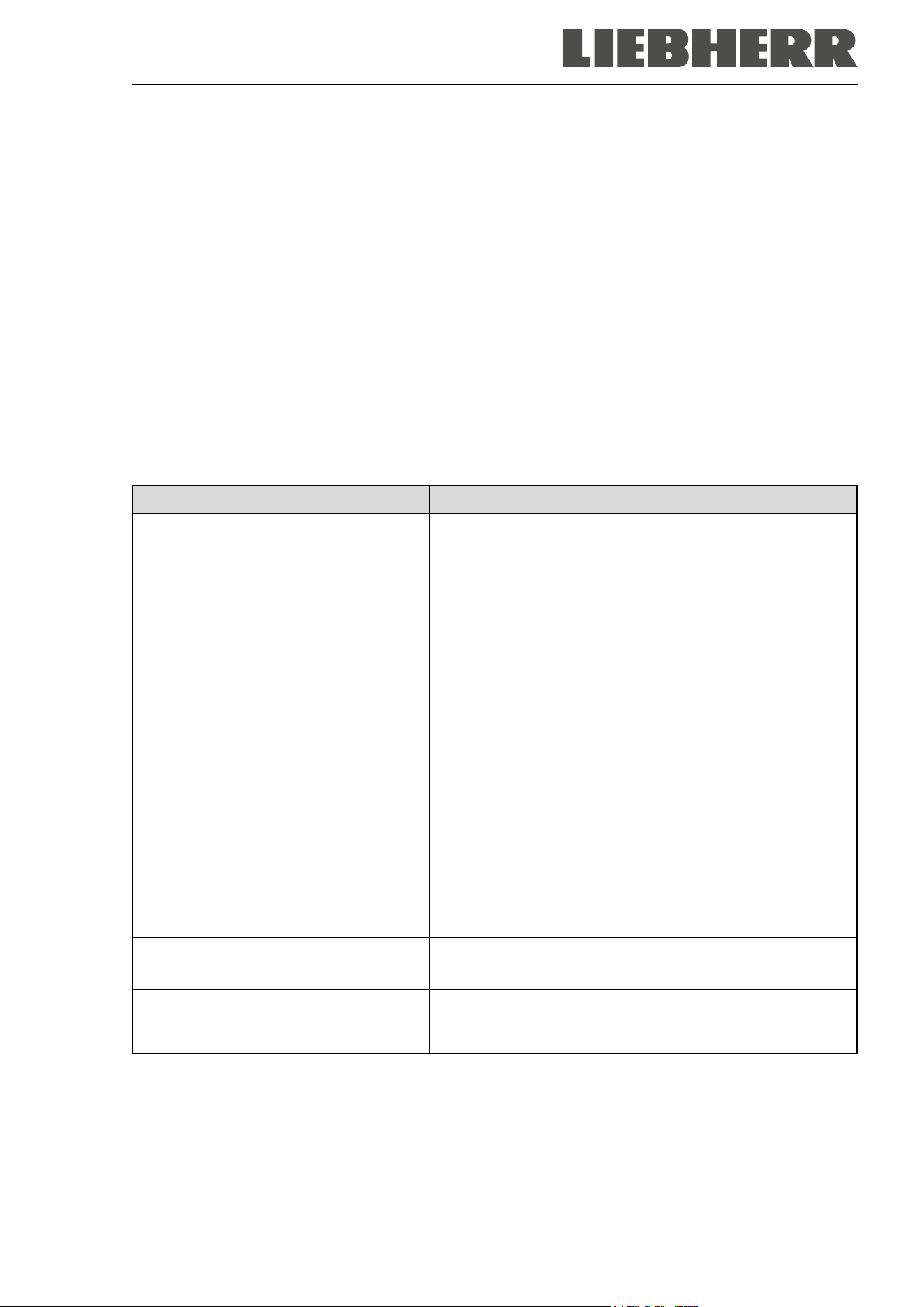
SUFsg 12/2024 Page 39/112
5.1 Menu structure of the controller and access levels
Starting from Normal display, navigate between the menus with the arrow buttons.
With the OK button you enter the setting of further subordinate menu functions.
With the Back button you go back to the previous function and finally back to Normal display.
The available functions depend on the current dependent on the current authorization “User”, “Admin” or
“Service”, for which the entry of a password may be required, depending on the setting.
You can set passwords for different access levels:
• User: The password enables access to the standard operating functions. Factory setting is 00 00 (no
password assigned).
• Admin: The password enables access to advanced controller functions and settings. Factory setting is
00 01.
• Service: The password enables access to all controller functions (for Service only).
As soon as a password has been assigned, access to the respective functions is blocked and only available
after entering the correct password.
Menu Required access level Functions
Setpoints “User”
• Temperature set-point setting
• CO
2
emergency cooling set-point setting (option
• Setting the safety controller
• Activating/deactivating the CO
2
emergency cooling (op-
tion) and the service setpoint, emergency cooling test (op-
tion)
Chamber info Any user
• Configuration display (setup information, controller hard-
ware and software, analog inputs)
• Display of battery condition (battery-buffered alarm sys-
tem)
•
Display of interface configuration (e.g. MAC address, IP
address)
Settings “Admin”
•
General controller settings (date, time, menu language,
temperature unit, display brightness…)
• Network settings
• Setting the data logger storage interval
• Setting the alarm limit for range alarm and delay times for
door open and range alarm, setting the service setpoint
• Password changing for User and Admin
Service “Service”
• Configuration settings (only for Service)
• Password changing for User and Admin
USB (visible
when inserting
a USB stick)
Export: Any user
Import: “Admin”
• Export of configuration, logger, and service data
• Import of configuration data
SUFsg 12/2024 Page 40/112
Unless noted otherwise, the figure in this manual show the functional range, which is available for the user
with “Admin” authorization level
Note: When specifying the path to the respective function, the possibly required entry of a password is not
listed.
6. Start up
Following transport, wait at least 8 hours until start-up.
Check that the interior of the freezer is empty. Prior to starting a new freezer or if you do not know what the
freezer was last used for, for hygiene purposes you should clean and disinfect the interior (chap. 23).
After connecting the supply lines, turn on the chamber by the main power switch (4) (position 1). The lit
pilot lamp shows the chamber is ready for operation.
The controller shows normal display and controls the temperature to the last entered values.
6.1 Preset factory parameters
The chamber is supplied with the following preset parameters, which can be changed in the corresponding
menus:
Temperature set point -80 °C / -112 °F
Safety controller
Set point type “Limit”
-65 °C / -85 °F
The maximum permitted deviation from the temperature set point as alarm limit
for range alarm
+/- 5 K
Alarm delay time after opening the door
1 minute
Alarm delay time after leaving the alarm limit for range alarm
(Following opening the door or chamber startup, the range alarm becomes valid
only after the setpoint has been reached)
60 minutes
Password for “User” authorization
0 (no locking)
Password for “Admin” authorization
1
6.2 Behavior after turning on the chamber
During the equilibration phase of approx. 8 hours after turning on the chamber, undefined temperature
conditions occur within the chamber. During this phase, do not place any sample materials in the chamber
NOTICE
Danger of temperature fluctuation.
Destruction of samples.
Load the freezer only after equilibration of temperature.
NOTICE
Malfunction of the door control depending on the time of day.
Longer time until the door reopens.
Set the correct date and time on the controller.
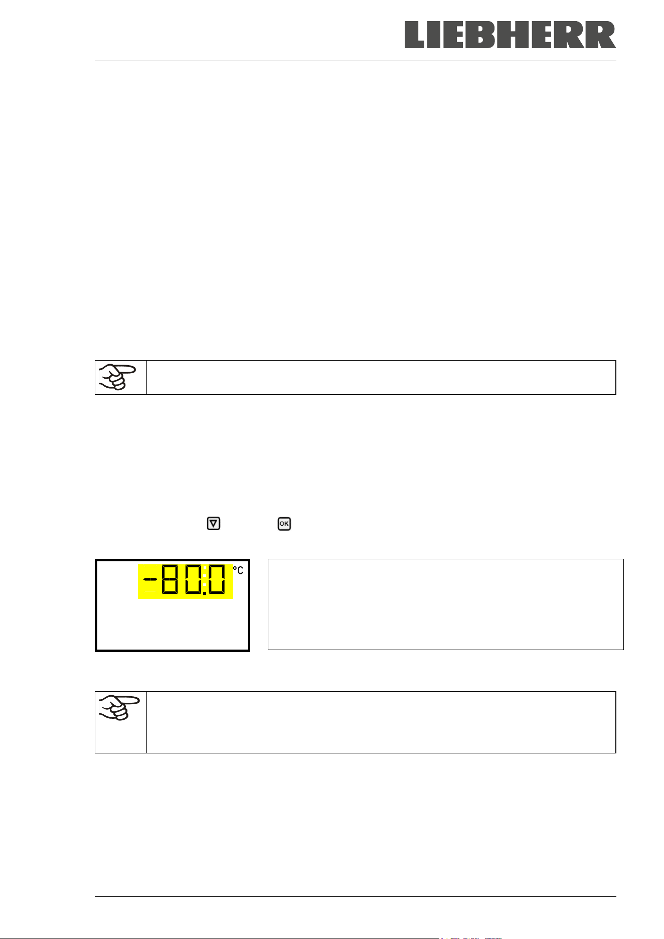
SUFsg 12/2024 Page 41/112
If the function “Language selection at restart” has been activated (chap. 12.5, factory setting ON), the fol-
lowing settings are checked upon start up:
• Menu language (chap. 12.1):
Use the arrow buttons to select the desired language, confirm with the OK button
• Temperature unit (chap. 12.2):
Use the arrow buttons to select the desired temperature unit, confirm with the OK button.
• Current date (chap. 12.3), format DD MM YYYY:
Use the arrow buttons to set the day, continue with the OK button.
Use the arrow buttons to set the month, continue with the OK button.
Use the arrow buttons to set the year, confirm with the OK button
• Current time (chap. 12.4), format HH:MM:
Use the arrow buttons to set the hours, continue with the OK button.
Use the arrow buttons to set the minutes, confirm with the OK button
Set the controller to the desired temperature set point (chap. 7) used to operate the freezer.
As long as there is a difference between the actual and set value shown in the display, the
intended operation of the chamber will not be ensured.
7. Temperature set-point entry
Required access level: “User”.
Setting and control range: -40 ºC / -40 ºF up to -90 °C / -130 °F
To set a lower setpoint value for test purposes or for adjustment, you can enter and activate a service
setpoint (chap. 19). This setting is outside the control range and is not intended for normal operation.
Path: Normal display Setpoints Temperature
Press the OK button to enable the setting.
Temperature setting.
The current setting flashes. Enter the desired set-point with the arrow
buttons.
Confirm the entry with the OK button.
Temperature
With the Back button you can go back to the “Setpoints” submenu and, repeatedly pressing it, to Normal
display.
With safety controller mode “Limit”, adapt the safety controller always when you changed the
temperature set-point. Set the safety controller value by approx. 15 °C above the temperature
set-point (chap. 11).
Recommended setting: safety controller mode “Offset” with safety controller value 15 °C.
Only insert samples into the freezer when it has reached its stable operating state.
Temperature equilibrating time to -80 °C / -112 °F is approx. 3 hours (SUFsg 3501) / approx. 6 hours
(SUFsg 5001) / approx. 7.5 hours (SUFsg 7001).
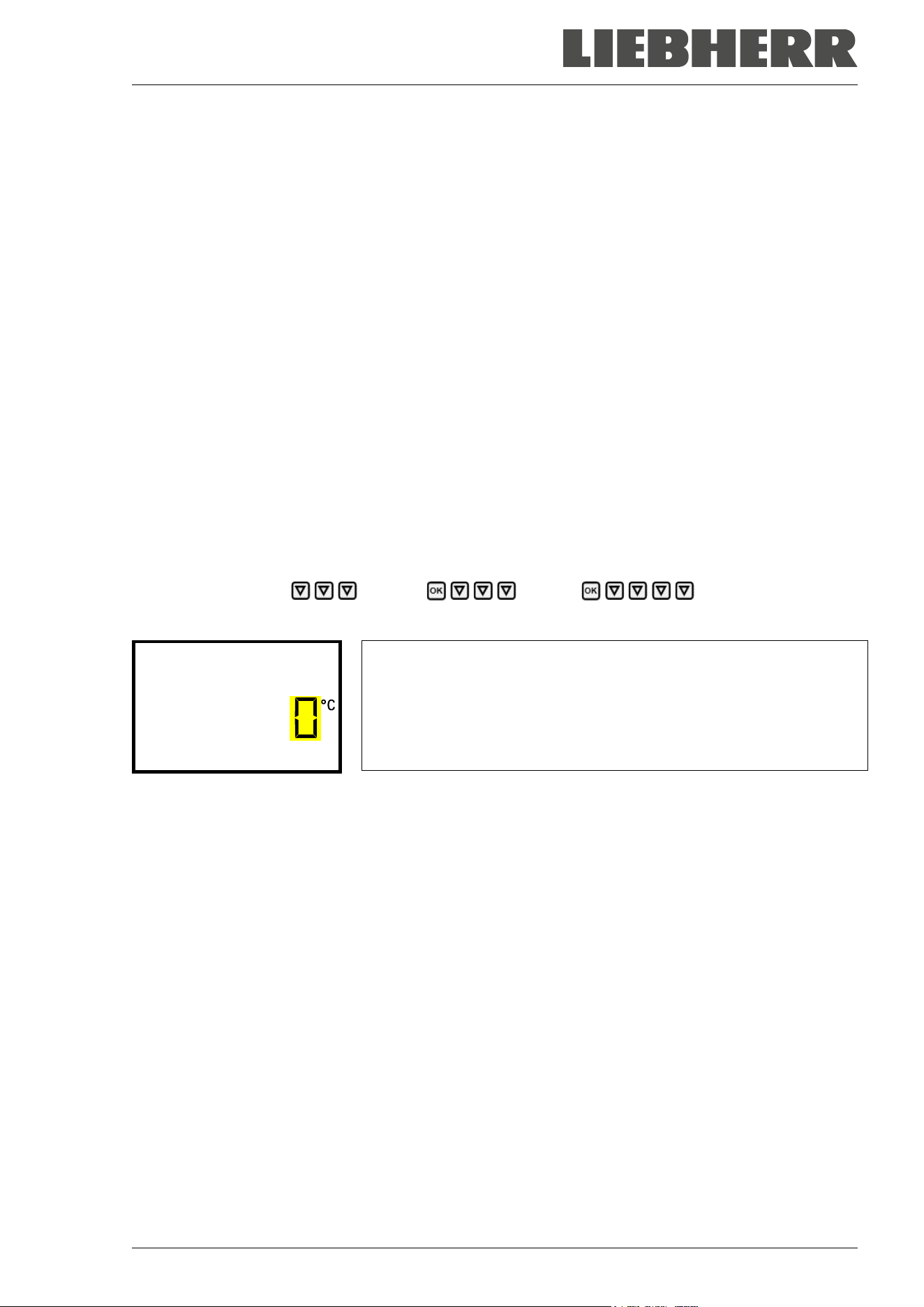
SUFsg 12/2024 Page 42/112
7.1 Setting the Manual Offset value
A spatial temperature measurement shows that the range in which all temperature values are located is not
symmetrical to the setpoint: The mean value of this temperature range deviates from the current setpoint
in a positive or negative direction.
If desired, the deviation of the mean value of the spatial temperature range from the setpoint can be com-
pensated for by setting a Manual Offset value.
This manual offset value is added to the setpoint or subtracted from it and results in a new working setpoint
for the control. The original setpoint remains visible in the controller display.
Example of calculation:
Setpoint: -80 °C
The limits of all temperature sensors in a spatial temperature measurement are in a range between -81 °C
and -77 °C; the middle of this range is -79 °C
The deviation of this mean value from the entered setpoint is therefore +1 K.
The setting value for the manual offset would then be: -1 K
Setting:
Required access level: “Admin”.
Path: Normal display Settings Various Manual Offset
Press the OK button to enable the setting.
Setting the Manual Offset
The current setting flashes. Use the arrow buttons to enter the de-
sired value. Entry range: -6 K up to 6 K, Factory setting: 0 K.
Confirm the setting with the OK button.
Manual Offset
With the arrow-up button you can go to setting the alarm limit for Service setpoint (chap. 19.1).
With the Back button you can go back to the “Various” submenu and, repeatedly pressing it, to Normal
display.
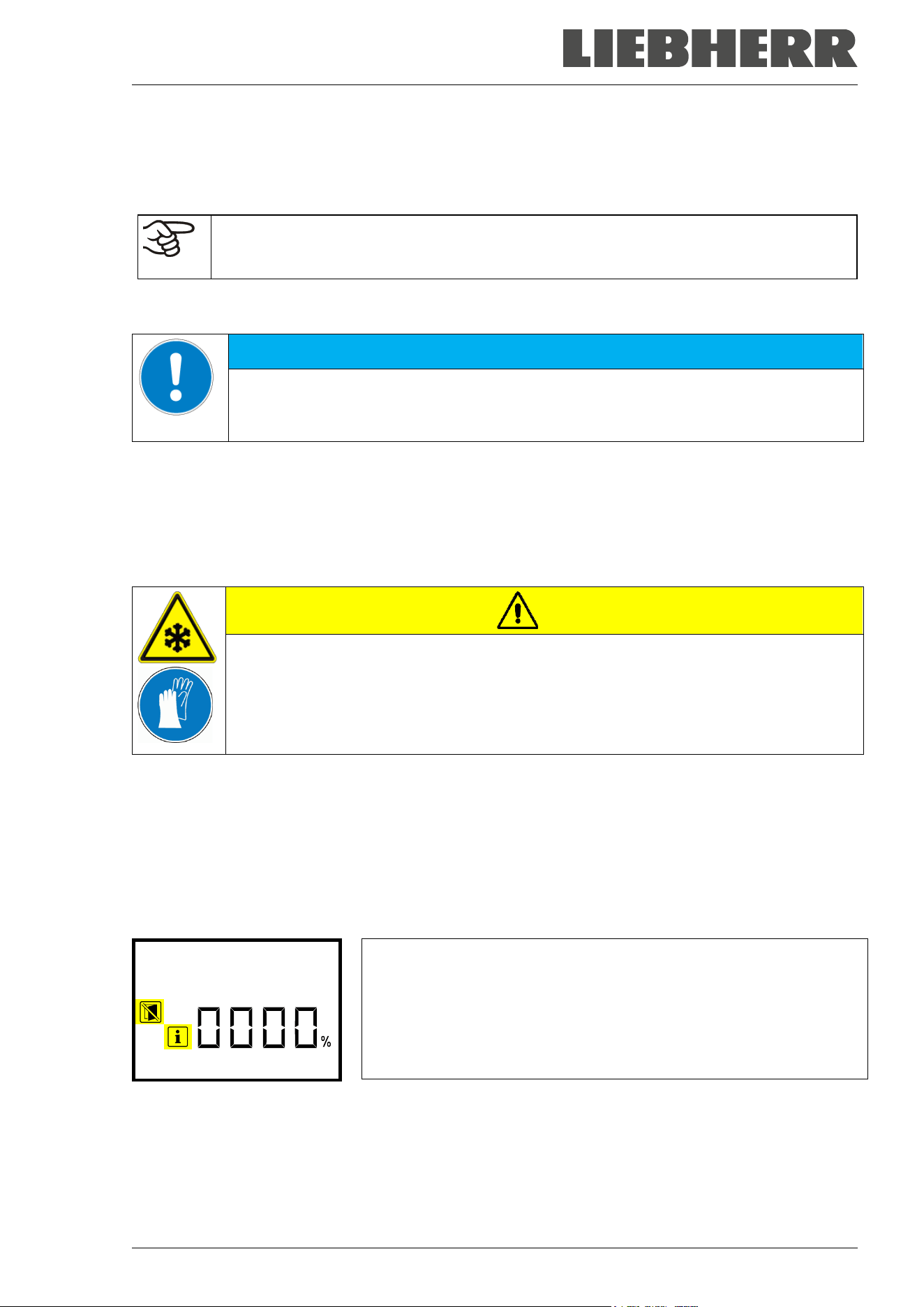
SUFsg 12/2024 Page 43/112
8. Placing samples in storage in the freezer
Before storing valuable samples, conduct a 10-days test run at the desired temperature. This helps to detect
transport damages like capillary cracks. Then you can load the freezer with the precooled samples.
WARNING: If customer should use a freezer running in non-supervised continuous opera-
tion, we strongly recommend in case of inclusion of irrecoverable specimen or samples to
split such specimen or samples and store them in at least two chambers, if this is feasible.
During the equilibration phase of approx. 8 hours after turning on the chamber, undefined temperature
conditions occur within the chamber. During this phase, do not place any sample materials in the chamber
NOTICE
Danger of temperature fluctuation.
Destruction of samples.
Load the freezer only after equilibration of temperature.
When placing not precooled samples in storage, temperature rises inside the freezer. We recommend to
successively load the freezer. The more thermal energy you bring in, the longer it takes until reaching the
set-point temperature again.
Do not exceed the maximum load of each compartment and the permitted total load (see chap.26.3).
The inner surfaces become very cold during operation. Always wear protective gloves when opening the
freezer and bringing in or removing material.
CAUTION
Danger of injury by freezing on when touching cold chamber parts during operation.
Local frostbite.
∅ Do NOT directly touch the inner surfaces or the charging material during operation.
∅ AVOID skin contact with the inner surfaces and accessory equipment.
Wear protective gloves when opening the inner doors and during manipulation.
After the outer door has been closed, it can only be opened again after a waiting time. This time depends
dynamically on the length of time since the door was last opened:
• More than 7 days since the door was last opened: 90 seconds waiting time
• Less than 7 days but more than 24 hours since the door was last opened: 70 seconds waiting time
• Less than 24 hours since the door was last opened: 30 seconds waiting time
The waiting time is displayed on the controller in Normal display as a countdown. In addition, the information
icon is lit, and the icon “Do not open the door” flashes.
Normal display during the waiting time after the outer door has been
closed (example)
Wait 56s
Note: If the door has not been opened for a longer period of time (more than 5 days), it is advisable to de-
ice the door gaskets and the inner opening of the pressure compensation valve (I) (see chap. 24.2.3). After
that, the door can be opened even after a short period of time without applying great force.
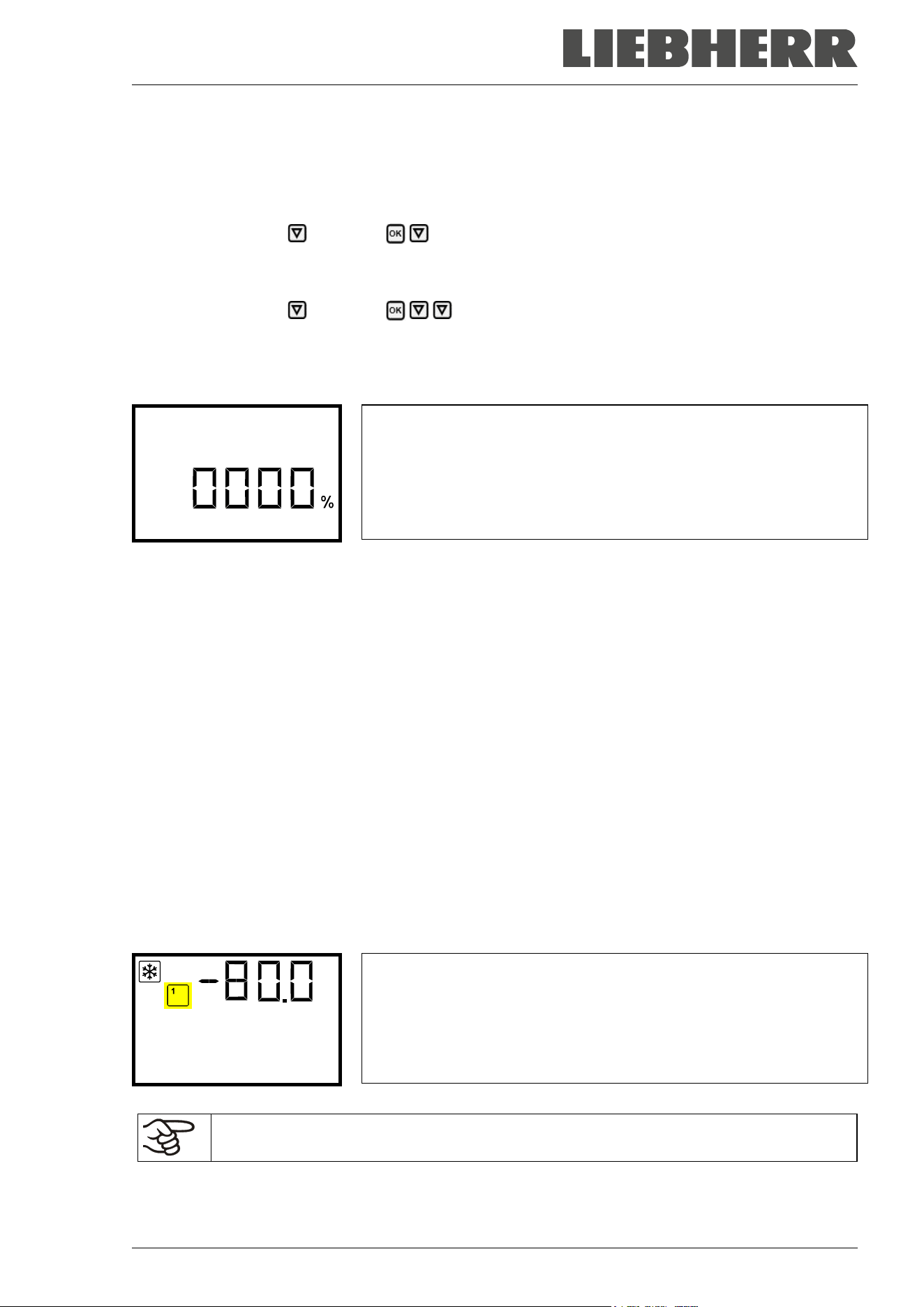
SUFsg 12/2024 Page 44/112
9. Setting special controller functions
In the “Functions on/off” menu you can define the switching state of up to 4 controller functions.
Required access level: “User”.
Path: Normal display Setpoints Functions on/off
With optional CO
2
emergency cooling:
Path: Normal display Setpoints Functions on/off
The functions are displayed from left to right.
Example: Function 1 activated = 1000. Function 1 deactivated = 0000.
Submenu “Functions on/off”.
This view shows the switching states of the four available functions.
“1” = Function activated
“0” = Function deactivated
Functions on/off
Press the OK button to access the first individual function. With the arrow-down button you can proceed
to the subsequent functions.
The functions 1 and 2 are only available with the chamber with optional CO
2
emergency cooling.
• Function 1 “CO2 emer.cooling on/off”: Activating the CO
2
emergency cooling, chap. 20.3.2
• Function 2 “CO2 cooling test on/off”: Tes t run of the CO
2
emergency cooling, chap. 20.3.3
• Function 3 “Service setpoint on/off”: Activating the service setpoint, chap. 19.2
• Function 4 has no function with this chamber type.
Press the OK button to enable the setting of the desired function and select the function’s switching state
“1” (function activated) or “0” (function deactivated).
With the Back button you can go back to the “Setpoints” submenu and, repeatedly pressing it, to Normal
display.
In Normal display the activated functions are indicated by an icon showing the number of the respective
function.
Example:
Normal display with activated function 1 “CO2 emer.cooling on/off”
Temperature
The settings for the CO
2
emergency cooling (option) are described in chap. 20.
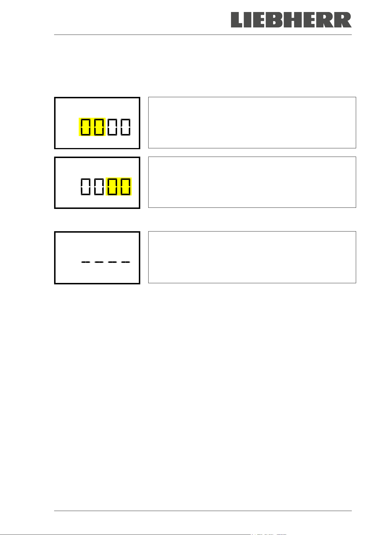
SUFsg 12/2024 Page 45/112
10. Password
10.1 Password request
To access menus for which access is restricted, you must enter the corresponding password.
After calling the appropriate menu function with the OK button the password request appears.
Password request.
The left two digits are flashing. Enter the desired numbers with the ar-
row buttons.
Confirm the setting with the OK button.
Password
Password request.
The right two digits are flashing. Enter the desired numbers with the ar-
row buttons.
Confirm the setting with the OK button.
Password
Upon entering an incorrect password, the message “Wrong password” is displayed.
Display “Wrong password”.
After 3 seconds the controller changes again to the password entry.
Enter the correct password.
Wrong password
Following correct password entry, you can access the desired menu function.
10.2 Assign and modify a password
In this menu you can assign and modify the passwords of the “User” and “Admin” access levels.
Required access level: “Admin”.
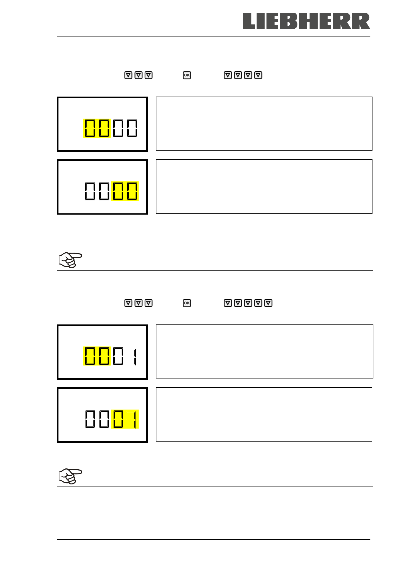
SUFsg 12/2024 Page 46/112
10.2.1 Assign and modify the User password
Path: Normal display Settings Chamber Password User
Press the OK button to enable the setting.
Setting the User password.
The left two digits are flashing. Enter the desired numbers with the ar-
row buttons.
Confirm the setting with the OK button.
Password User
Setting the User password.
The right two digits are flashing. Enter the desired numbers with the
arrow buttons.
Confirm the setting with the OK button.
Password User
With the arrow-down button you can now proceed to enter the Admin password.
With the Back button you can go back to the “Chamber” submenu and, repeatedly pressing it, to Normal
display.
Keep the password well in mind. There is no access to the corresponding menu functions
without the correct password.
10.2.2 Assign and modify the Admin password
Path: Normal display Settings Chamber Password Admin
Press the OK button to enable the setting.
Setting the Admin password.
The left two digits are flashing. Enter the desired numbers with the ar-
row buttons.
Confirm the setting with the OK button.
Password Admin
Setting the Admin password.
The right two digits are flashing. Enter the desired numbers with the
arrow buttons.
Confirm the setting with the OK button.
Password Admin
With the Back button you can go back to the “Chamber” submenu and, repeatedly pressing it, to Normal
display.
Keep the password well in mind. There is no access to the corresponding menu functions
without the correct password.
SUFsg 12/2024 Page 47/112
10.3 Performance during and after power failure and shut down
During a power supply failure, the battery maintains the controller functions. The controller display is dark
and can be activated for 5 seconds by pressing any button. The refrigerating machine is out of operation.
The chamber’s refrigerating function can be maintained through the CO
2
emergency cooling (option, chap.
19). The zero-voltage relay alarm output (9) (chap. 14.4.7) is switched for the whole duration of the power
failure.
After the power returns or when turned on by hand, all functions return to the same status the chamber had
before power failure. The freezer regulates the temperature to the last entered set point.
All settings and set point values remain in the memory during power failure after power off.
If an alarm has occurred caused by the power supply failure (e.g., range alarm, safety controller etc.),
confirm the alarm. See chap. 14.
11. Safety controller (temperature safety device)
The SUFsg freezer is equipped with an electronic over temperature safety device. It is designated as the
“safety controller”. This second, electrically independent temperature controller emits an alarm at a se-
lectable set point in case of fault. Thus it serves to protect the charging material against excessively high
temperatures. This condition (state of alarm) is indicated visually and additionally with an audible alert if the
buzzer is enabled (chap. 14.3). The alarm persists until the chamber cools down below the configured
safety controller value and the alarm is reset on the controller. The safety controller is independent of the
temperature control system.
Please observe the regulations applicable to your country.
Regularly check the safety controller setting. Set the safety controller set point by approx.
15 °C above the desired temperature set point.
The safety controller only activates after the set-point has been reached. This condition must
be met every time the door was opened.
The settings of the safety controller are inactive during battery operation, open door, power
failure, CO
2
emergency cooling (option). They become functional again following restitution of
power supply and/or the restart of the chamber with the main power switch (4).
You can set the safety controller mode to “Limit” or “Offset”.
• Limit: Limit value, absolute maximum permitted temperature value
This setting offers high safety as a defined temperature limit will not be exceeded. It is important to adapt
the safety controller value after each modification of the temperature set-point. Otherwise, the limit could
be too high to ensure efficient protection, or, in the opposite case, it could prevent the controller from
reaching an entered set-point outside the limit range.
• Offset: Offset value, maximum overtemperature above any active temperature set point. The resulting
maximum temperature changes internally and automatically with every temperature set-point change.
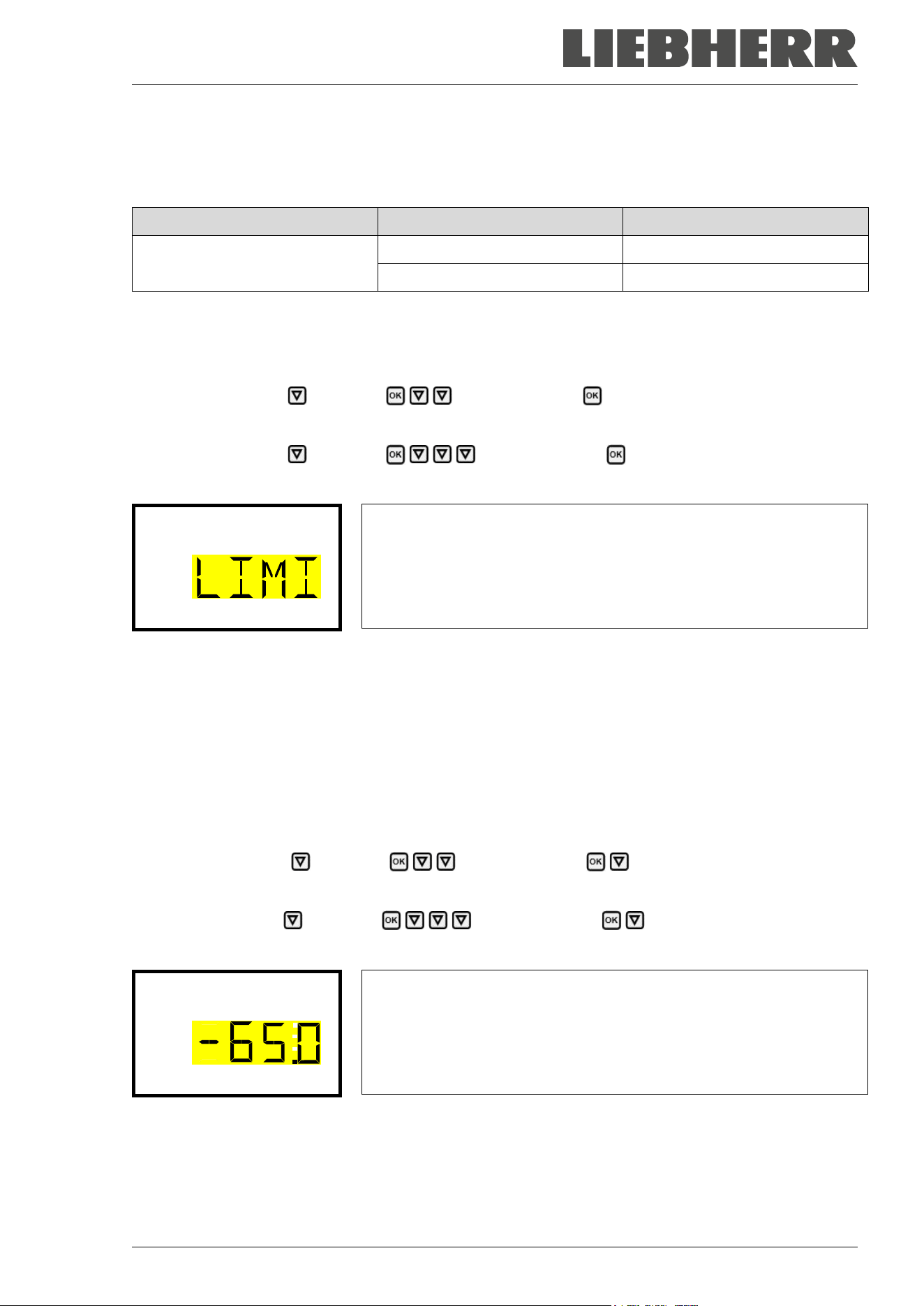
SUFsg 12/2024 Page 48/112
Example:
Desired temperature value: -80 °C, desired safety controller value: -65 °C.
Possible settings for this example:
Temperature set point Safety controller mode Safety controller value
-80 °C
Limit Limit value -65 °C
Offset Offset value 15 °C
11.1 Setting the safety controller mode
Required access level: “User”.
Path: Normal display Setpoints Safety controller Mode
With optional CO
2
emergency cooling:
Path: Normal display Setpoints Safety controller Mode
Press the OK button to enable the setting.
Setting the safety controller mode
The current setting flashes. Use the arrow buttons to select between
LIMI (Limit) and OFFS (Offset).
Confirm the setting with the OK button.
Mode
With the arrow-down button you proceed to setting the safety controller value (chap. 11.2)
With the Back button you can go back to the “Safety controller” submenu and, repeatedly pressing it, to
Normal display.
11.2 Setting the safety controller value
Required access level: “User”.
The desired safety controller mode must be selected first (chap. 11.1). Depending on the mode setting, one
of the following setting menus will appear.
Path: Normal display Setpoints Safety controller Limit or Offset
With optional CO
2
emergency cooling:
Path Normal display Setpoints Safety controller Limit or Offset
Press the OK button to enable the setting.
Setting the safety controller value with “Limit” safety controller mode.
The current value flashes. Enter the desired limit value with the arrow
buttons. Setting range: -20 °C to -110 °C.
Confirm the entry with the OK button.
Limit
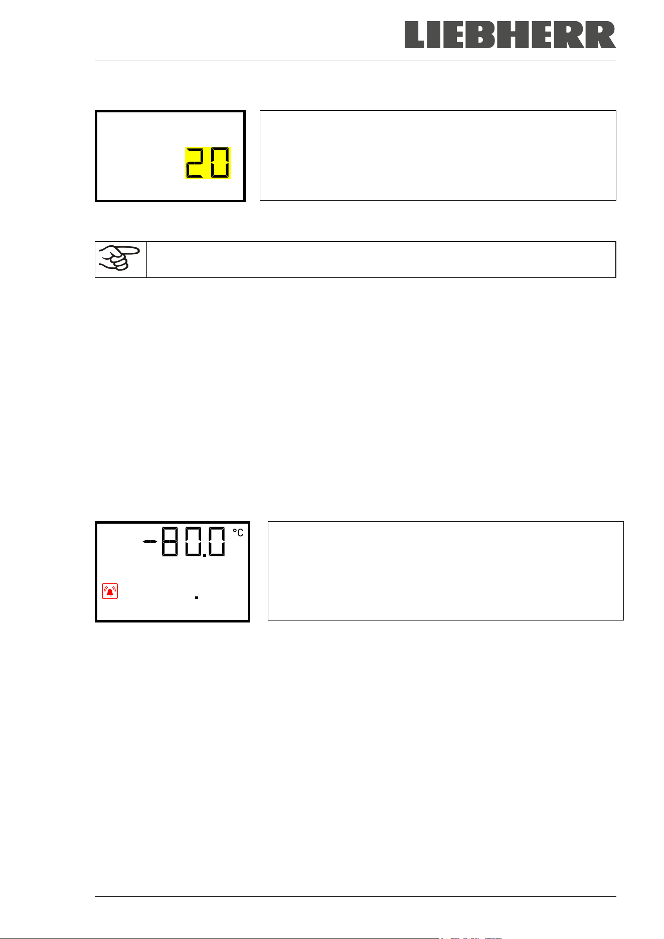
SUFsg 12/2024 Page 49/112
Or
Setting the safety controller value with “Offset” safety controller mode
The current value flashes. Enter the desired offset value with the
arrow buttons.
Confirm the entry with the OK button.
Offset
With the Back button you can go back to the “Safety controller” submenu and, repeatedly pressing it, to
Normal display.
Regularly check the settings of the safety controller mode and value.
Set the safety controller value by approx. 15 °C above the desired temperature set-point.
11.3 Message and measures in the state of alarm
The state of alarm is indicated visually in Normal display. If the buzzer is enabled (chap. 14.3) there is an
additional audible alert. A text message indicates the alarm cause. The “collective alarm” icon is lit. If the
audible arm is activated, the buzzer sounds. Press the OK button to mute the buzzer.
The alarm message “Safety controller” and the “Collective alarm” icon are displayed on the controller until
you press the OK button on the controller and the inner chamber temperature has cooled down below the
safety controller value.
• If the inner chamber temperature has already cooled down below the safety controller value when press-
ing the OK button, the alarm message “Safety controller” and the “Collective alarm” icon are reset
together with the buzzer.
• If the state of alarm is still active when pressing the OK button, i.e. the inner chamber temperature is
still above the safety controller value, first only the buzzer is reset. The alarm message “Safety controller”
and the “Collective alarm” icon will disappear as soon as the inner chamber temperature falls below the
safety controller value.
Normal display showing safety controller alarm (sample value)
Safety controller
Note:
When the safety controller had been activated you should transfer the samples into another freezer and
then disconnect the chamber from the power supply and have an expert examine and rectify the cause of
the fault.
11.4 Function check
Check the safety controller at appropriate intervals for its functionality. It is recommended that the author-
ized operating personnel should perform such a check, e.g., before starting a longer work procedure.
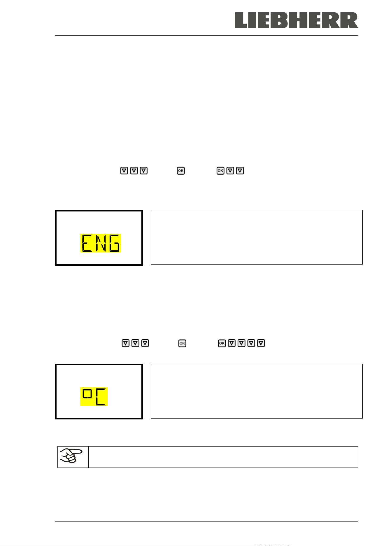
SUFsg 12/2024 Page 50/112
12. General controller settings
The general settings can be accessed in the “Settings” submenu, which is available for users with “Service”
or “Admin” authorization level. It serves to enter date and time, select the language for the controller menus
and the desired temperature unit and to configure the controller’s communication functions.
The display of some network settings is available for all users in the “Chamber info” menu.
12.1 Selecting the controller’s menu language
The chamber controller communicates by a menu guide using real words in German, English, French,
Spanish, and Italian languages.
Required access level: “Admin”. Following start-up of the chamber (chap. 6), it is “User”.
Path: Normal display Settings Chamber Language*
* Following start-up of the chamber: Sprache / Language / Langue / Idioma / Lingua, depending on the
language selected before turning off the chamber
Press the OK button to enable the setting.
Setting the menu language (example: English).
The current setting flashes. Use the arrow buttons to select the desired
language.
Confirm the entry with the OK button.
Language
With the arrow-down button (twice) you can now change to the temperature unit setting.
With the Back button you can go back to the “Chamber” submenu and, repeatedly pressing it, to Normal
display.
12.2 Selecting the temperature unit
Required access level: “Admin”. Following start-up of the chamber (chap. 6), it is “User”.
Path: Normal display Settings Chamber Temperature unit
Press the OK button to enable the setting.
Setting the temperature unit
The current setting flashes. Use the arrow buttons to select between
°C (degrees Celsius) and °F (degrees Fahrenheit).
Confirm the entry with the OK button.
Temperature unit
You can change the temperature unit between °C and °F.
If the unit is changed, all values are converted accordingly
C = degree Celsius
F= degree Fahrenheit
0 °C = 31 °F
100 °C = 212 °F
Conversion:
[value in °F] = [value in °C] ∗ 1,8 + 32
With the Back button you can go back to the “Chamber” submenu and, repeatedly pressing it, to Normal
display.
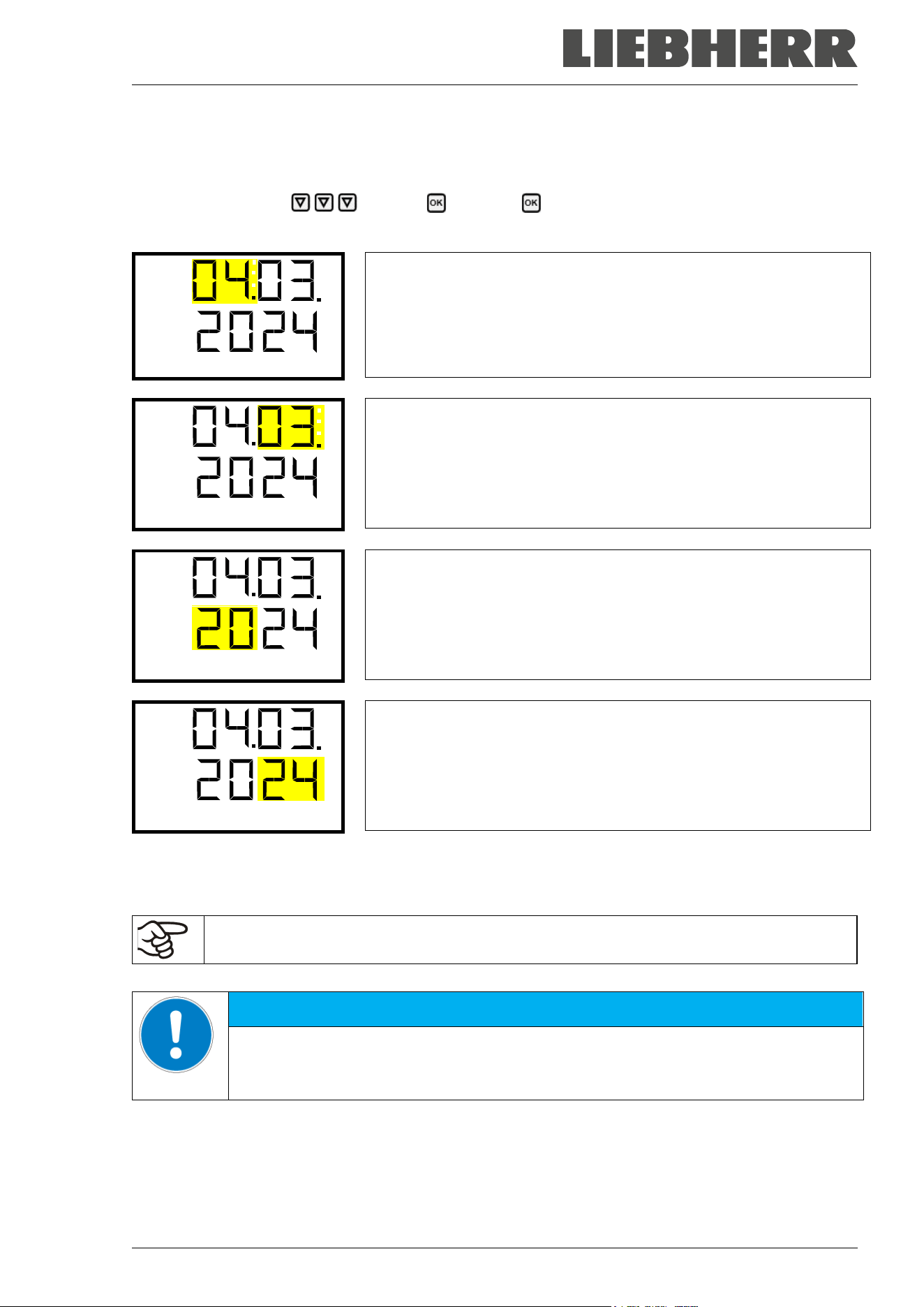
SUFsg 12/2024 Page 51/112
12.3 Setting the current date
Required access level: “Admin”. Following start-up of the chamber (chap. 6), it is “User”.
Path: Normal display Settings Chamber Date
Press the OK button to enable the setting.
Setting the date: day
The current setting flashes. Enter the current day with the arrow but-
tons.
Confirm the entry with the OK button.
Date
Setting the date: month
The current setting flashes. Enter the current month with the arrow
buttons.
Confirm the entry with the OK button.
Date
Setting the date: year
The left two digits are flashing. Enter the first two digits of the current
year with the arrow buttons.
Confirm the entry with the OK button.
Date
Setting the date: year
The right two digits are flashing. Enter the last two digits of the current
year with the arrow buttons.
Confirm the entry with the OK button.
Date
With the arrow-down button you can now change to setting the current time.
With the Back button you can go back to the “Chamber” submenu and, repeatedly pressing it, to Normal
display.
Check the date when you use the chamber for the first time or when you change local sum-
mer time and adjust it if necessary.
NOTICE
Malfunction of the door control depending on the time of day.
Longer time until the door reopens.
Set the correct date on the controller.
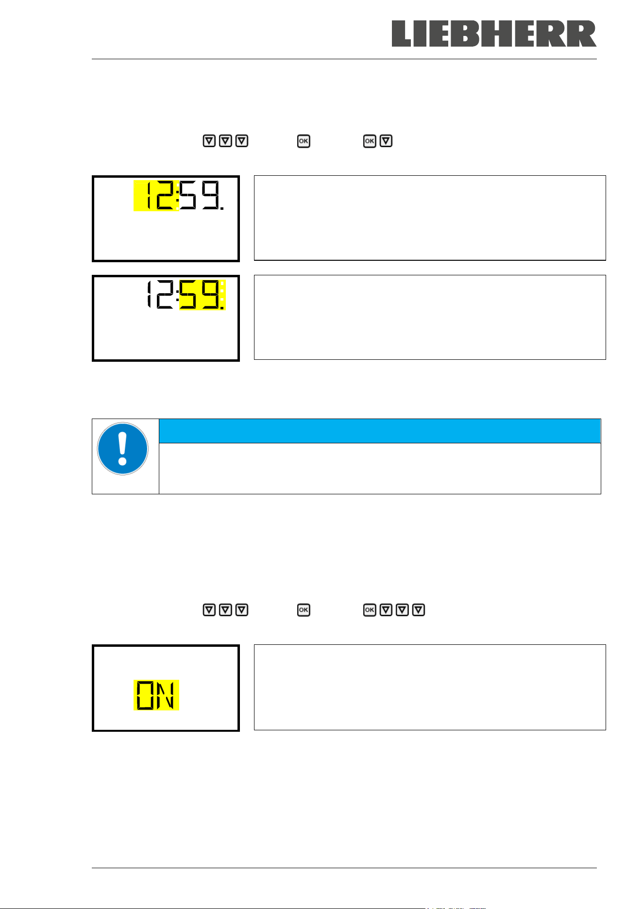
SUFsg 12/2024 Page 52/112
12.4 Setting the current time
Required access level: “Admin”. Following start-up of the chamber (chap. 6), it is “User”.
Path: Normal display Settings Chamber Time
Press the OK button to enable the setting.
Setting the time: hours
The current setting flashes. Enter the current hour with the arrow but-
tons.
Confirm the entry with the OK button.
Time
Setting the time: minutes
The current setting flashes. Enter the current minutes with the arrow
buttons.
Confirm the entry with the OK button.
Time
With the Back button you can go back to the “Chamber” submenu and, repeatedly pressing it, to Normal
display.
NOTICE
Malfunction of the door control depending on the time of day.
Longer time until the door reopens.
Set the correct time on the controller.
12.5 Function “Language selection at restart”
If the function “Language selection at restart” is activated, menu language, date, time, and temperature unit
are checked with every startup of the chamber. At this occasion it is also possible to modify them with
“User” access level.
Required access level: “Admin”.
Path: Normal display Settings Chamber Language selection at restart
Press the OK button to enable the setting.
Function “Language selection at restart”
The current setting flashes. Use the arrow buttons to select between
ON and OFF.
Confirm the setting with the OK button.
Language sel. at restar
With the arrow-down button you can now change to the next parameter (chamber address).
With the Back button you can go back to the “Chamber” submenu and, repeatedly pressing it, to Normal
display.
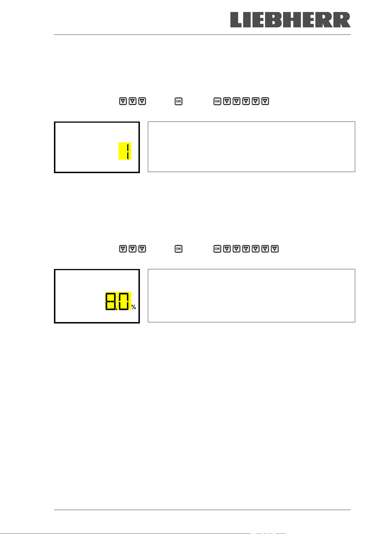
SUFsg 12/2024 Page 53/112
12.6 Setting the chamber address
This setting is required for computer communication. The chamber address settings in the chamber con-
troller and in any software must be identical.
Required access level: “Admin”.
Path: Normal display Settings Chamber Chamber address
Press the OK button to enable the setting.
Setting the chamber address
The current setting flashes. Enter the desired address with the arrow
buttons. Setting range: 1 up to 254
Confirm the entry with the OK button.
Chamber address
With the arrow-down button you can now change to the next parameter (display brightness).
With the Back button you can go back to the “Chamber” submenu and, repeatedly pressing it, to Normal
display.
12.7 Display brightness
Required access level: “Admin”.
Path: Normal display Settings Chamber Brightness
Press the OK button to enable the setting.
Setting the display brightness
The current setting flashes. Enter the desired value with the arrow but-
tons. Setting range: 10% up to 100%
Confirm the entry with the OK button.
Brightness
With the arrow-down button you can now change to the next parameter (audible alarm, chap. 14.3).
With the Back button you can go back to the “Chamber” submenu and, repeatedly pressing it, to Normal
display.
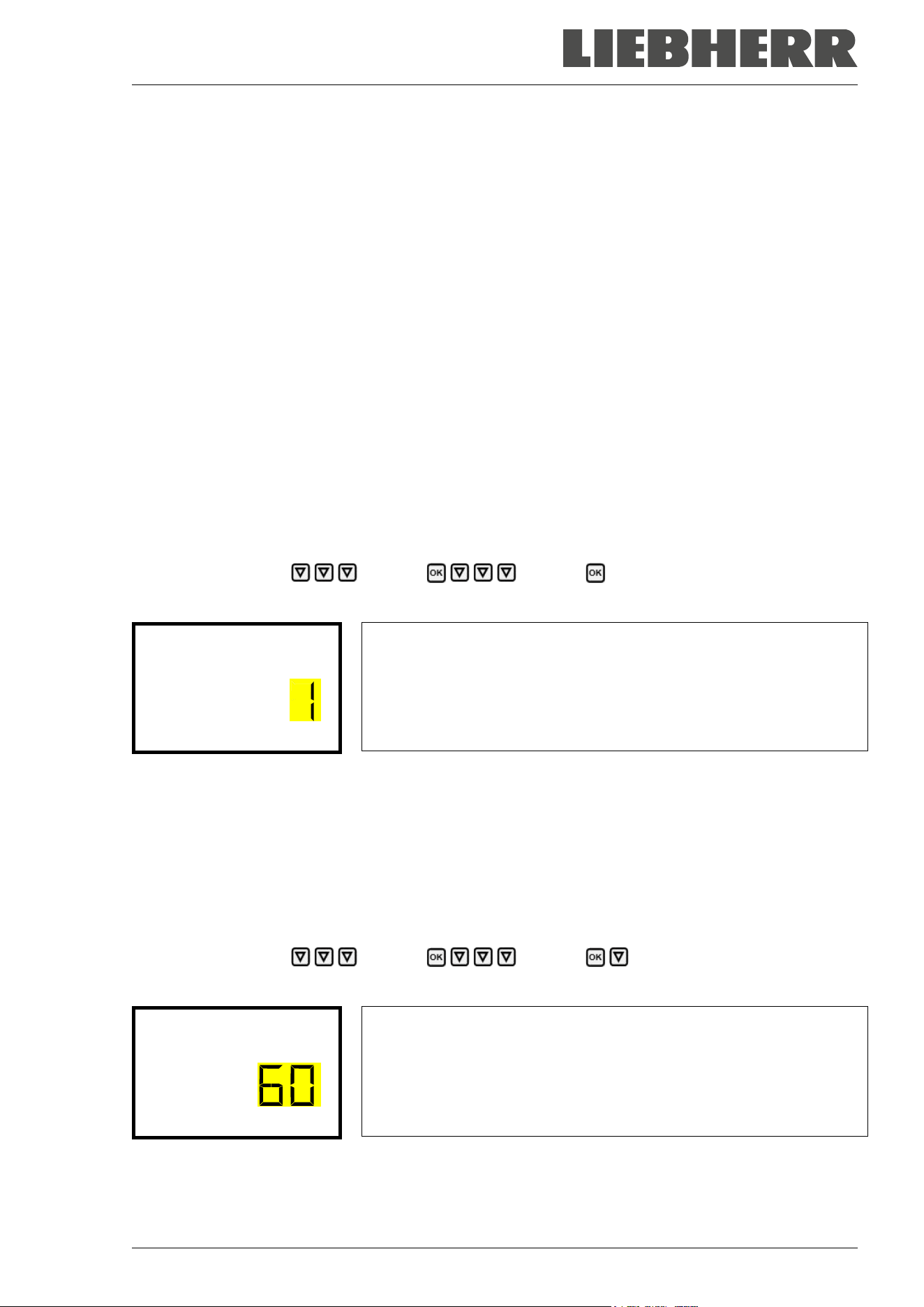
SUFsg 12/2024 Page 54/112
13. Setting the alarm limit for range alarm and the alarm delays
In this menu you can define the deviation between the actual value and setpoint of, which that shall cause
a range alarm. The entered value defines the limit of permitted deviations from the set-point (exceeding
and falling below). Reaching this limit triggers a range alarm.
In addition, you can specify a delay time for the range alarm and the door open alarm.
During the delay time there is no alarm message after leaving the alarm limit of the range alarm:
• After turning on the chamber or returning power supply or after a door opening in case the set-point
hasn’t been reached: fixed delay time of 15 hours
• After leaving the alarm limit of the range alarm in normal operation: adjustable delay time (chap. 13.2)
If the actual value is outside the alarm limit of the range alarm, after the configured alarm delay time the
alarm message “Temperature range” is displayed in Normal display (chap. 14.1). If the alarm buzzer is
activated (chap. 14.3) there is an audible alert.
This function only activates after the set-point has been reached. This condition must be met every time
the door was opened.
Required access level: “Admin”.
13.1 Setting the delay time for door open alarm
Path: Normal display Settings Various Door alarm delay (min)
Press the OK button to enable the setting.
Setting the door alarm delay.
The current setting flashes. Use the arrow buttons to enter the desired
time after which the door open alarm shall be triggered. Entry range: 1
up to 600 minutes. Factory setting: 1 minute.
Confirm the entry with the OK button.
Door alarm delay (min
With the arrow-down button you can now change to the range alarm delay setting.
With the Back button you can go back to the “Various” submenu and, repeatedly pressing it, to Normal
display.
13.2 Setting the delay time for range alarm
Following opening the door or chamber startup, the range alarm becomes valid only after the setpoint has
been reached.
Path: Normal display Settings Various Range alarm delay (min)
Press the OK button to enable the setting.
Setting the range alarm delay.
The current setting flashes Use the arrow buttons to enter the desired
time after which the range alarm shall be triggered. Entry range: 1 up to
300 minutes. Factory setting: 60 minutes.
Confirm the entry with the OK button.
Range alarm delay (mi
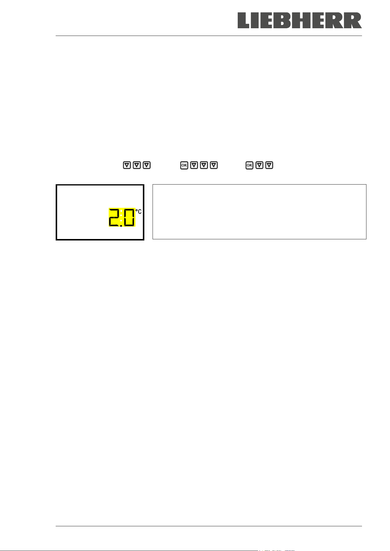
SUFsg 12/2024 Page 55/112
With the arrow-up button you can go back to the door alarm delay setting.
With the arrow-down button you can now change to setting the alarm limit of the range alarm.
With the Back button you can go back to the “Various” submenu and, repeatedly pressing it, to Normal
display.
13.3 Setting the alarm limit of the range alarm
A temperature range (alarm limit) is defined symmetrically around the setpoint. If the actual temperature
value lies within this alarm limit and subsequently leaves it, range alarm is triggered after the set adjustable
delay time (chap. 13.2)
Path: Normal display Settings Various Temperature range
Press the OK button to enable the setting.
Setting the temperature tolerance range (alarm limit)
The current setting flashes. Enter the desired temperature range with
the arrow buttons. Entry range: 1,0 °C up to 10,0 °C. Factory setting:
+/- 5 K
Confirm the entry with the OK button.
Temperature range
With the arrow-up button you can go back to the range alarm delay setting.
With the arrow-down button you can now change to the service setpoint setting (chap. 19.1).
With the Back button you can go back to the “Various” submenu and, repeatedly pressing it, to Normal
display.
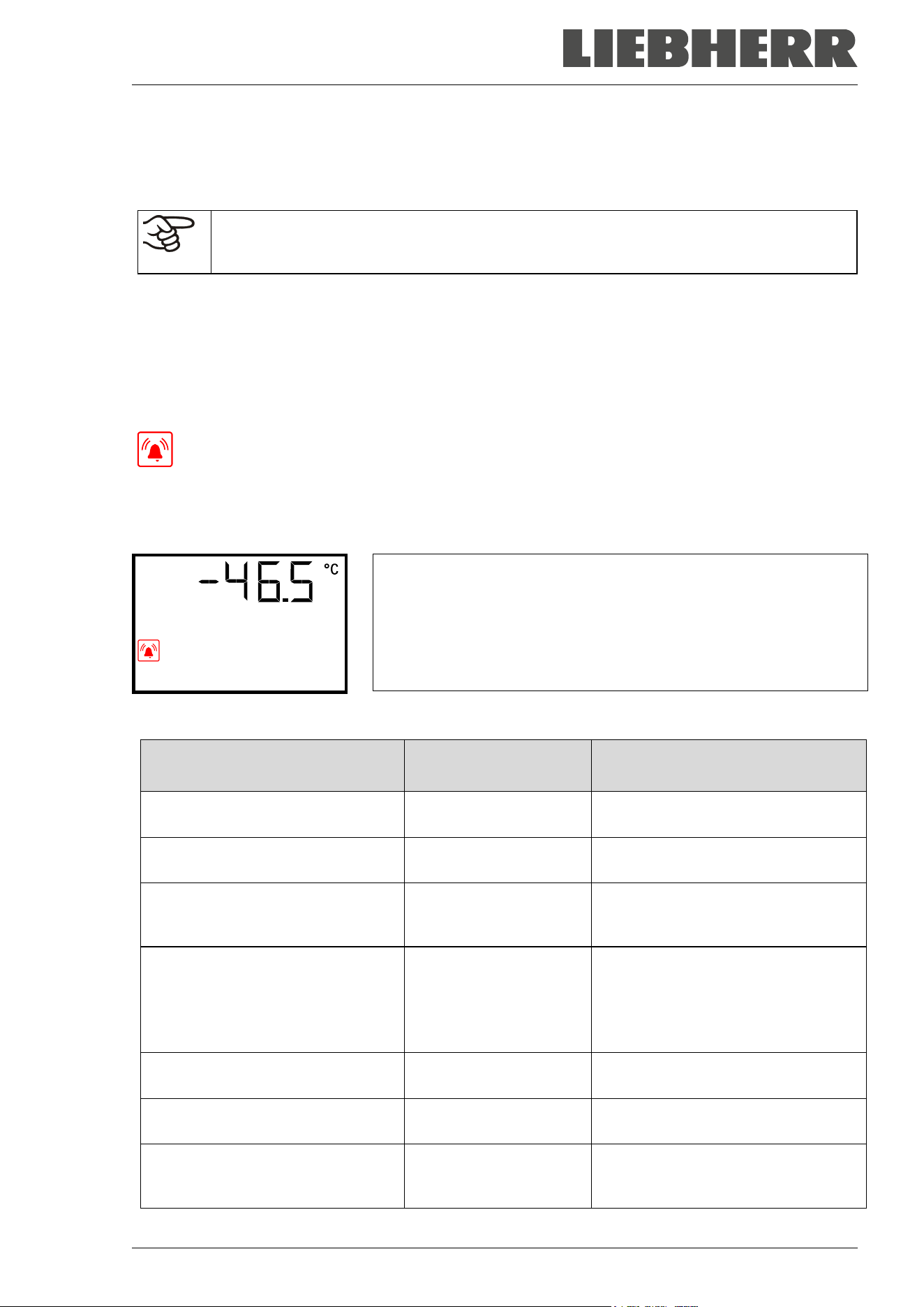
SUFsg 12/2024 Page 56/112
14. Alarm functions
14.1 Alarm messages
WARNING: If customer should use a chamber running in non-supervised continuous opera-
tion, we strongly recommend in case of inclusion of irrecoverable specimen or samples to
split such specimen or samples and store them in at least two chambers, if this is feasible.
In the event of equipment failures, when the temperature deviates from the alarm limit of the range alarm,
optical and possibly acoustic alarm messages are given out via the controller. A zero-voltage relay alarm
output (9) (chap. 14.4.7) permits transmission of the alarm e.g., to a central monitoring system.
The alarm messages door open and leaving the alarm limit of the range alarm are emitted after a configu-
rable delay (chap. 13), the others immediately when the fault occurs. The range alarm is suppressed after
opening the chamber door or turning on the freezer until the setpoint is reached and then for the selected
delay time.
In Normal display a text message indicates the alarm cause. The “collective alarm” icon flashes.
If the audible arm is activated, the buzzer sounds.
If more than one alarm signal is sent simultaneously, they are displayed in a cycle.
Press the OK button to confirm the alarm and mute the buzzer. If the alarm cause is still valid, the “collective
alarm” icon is lit.
Alarm indication (example: safety controller alarm)
Safety controller
Alarm messages overview:
Condition Alarm message
Moment of Alarm message and
switching the zero-voltage relay
alarm output
Chamber door open “Door open”
after configurable time (chap. 13).
Factory setting: 1 minute
Exceeded setpoint of the safety
controller
“Safety controller” immediately
The current actual temperature
value is outside the alarm limit of
the range alarm (chap. 13)
“Temp. range”
after configurable time (chap. 13).
Factory setting: 60 minutes
Continuous compressor operation,
refrigeration system defective. Con-
tact Service.
“Continuous operation”
• 15 hours after start-up or a door
opening, if the set-
point wasn’t
reached
• 60 minutes after reaching the set-
point
Clean / replace the condenser air
filter (chap. 24.2.1)
“Condenser temp.” after 10 hours
Compressor defective. Contact Ser-
vice.
“Compressor defective” immediately
Inner temperature sensor defective.
Control continues using the safety
controller temperature sensor
“Inner temp. sensor” immediately
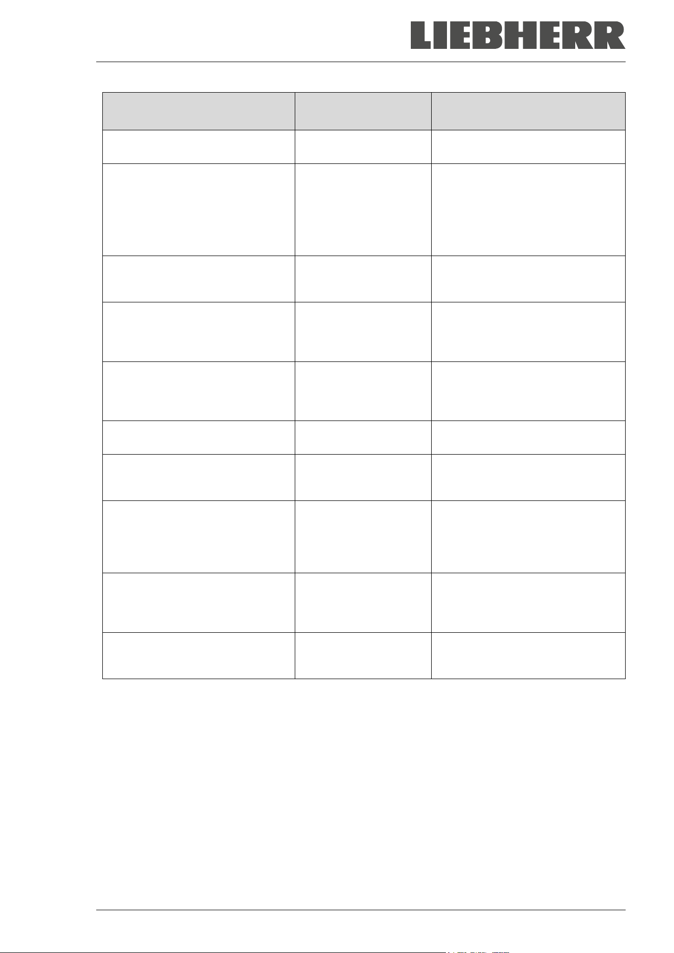
SUFsg 12/2024 Page 57/112
Condition Alarm message
Moment of Alarm message and
switching the zero-voltage relay
alarm output
Safety controller temperature sen-
sor defective
“Safety control sensor” immediately
Inner temperature sensor and
safety controller temperature sen-
sor defective. Refrigeration is
turned on permanently.
Temperature display
shows “- - - - ” or
“<-<-<” or “>->->”
Messages alternating:
“Inner temp. sensor” and
“Safety control sensor”
immediately
Failure of Pt100 temperature sen-
sor on the condenser of the refrig-
erating machine.
“Condensate temp.
sensor”
immediately
Failure of Pt100 temperature sen-
sor on the cascade of the refrigerat-
ing machine. Refrigeration is turned
on permanently.
“Cascade temp. sensor” immediately
Failure of Pt100 temperature sen-
sor for ambient temperature or air
intake of the 1
st
stage cooling (re-
frigerating machine).
“Ambient temp. sensor” immediately
Battery operation (during power fail-
ure)
“Battery operation” immediately
No battery recognized. Cause: Bat-
tery missing or defective. Message
on line power.
“Battery defective” immediately
Chamber with optional CO
2
emer-
gency cooling: activated CO
2
emer-
gency cooling automatically turned
on due to power failure and is run-
ning.
“CO2 emergency cooling”
immediately
Chamber with optional CO
2
emer-
gency cooling: Insufficient CO
2
sup-
ply of the activated CO
2
emergency
cooling system
“CO2 pressure” immediately
Power failure (chamber without bat-
tery or with message “Battery defec-
tive”)
-- immediately (alarm output only)
Press the OK button to confirm the alarm.
• Confirmation while the state of alarm persists: Only the buzzer is muted. The visual alarm message
continues to be displayed until the alarm condition is removed. Then it is reset automatically.
• Confirmation after the alarm has ended: The buzzer and the visual alarm message are rest together.
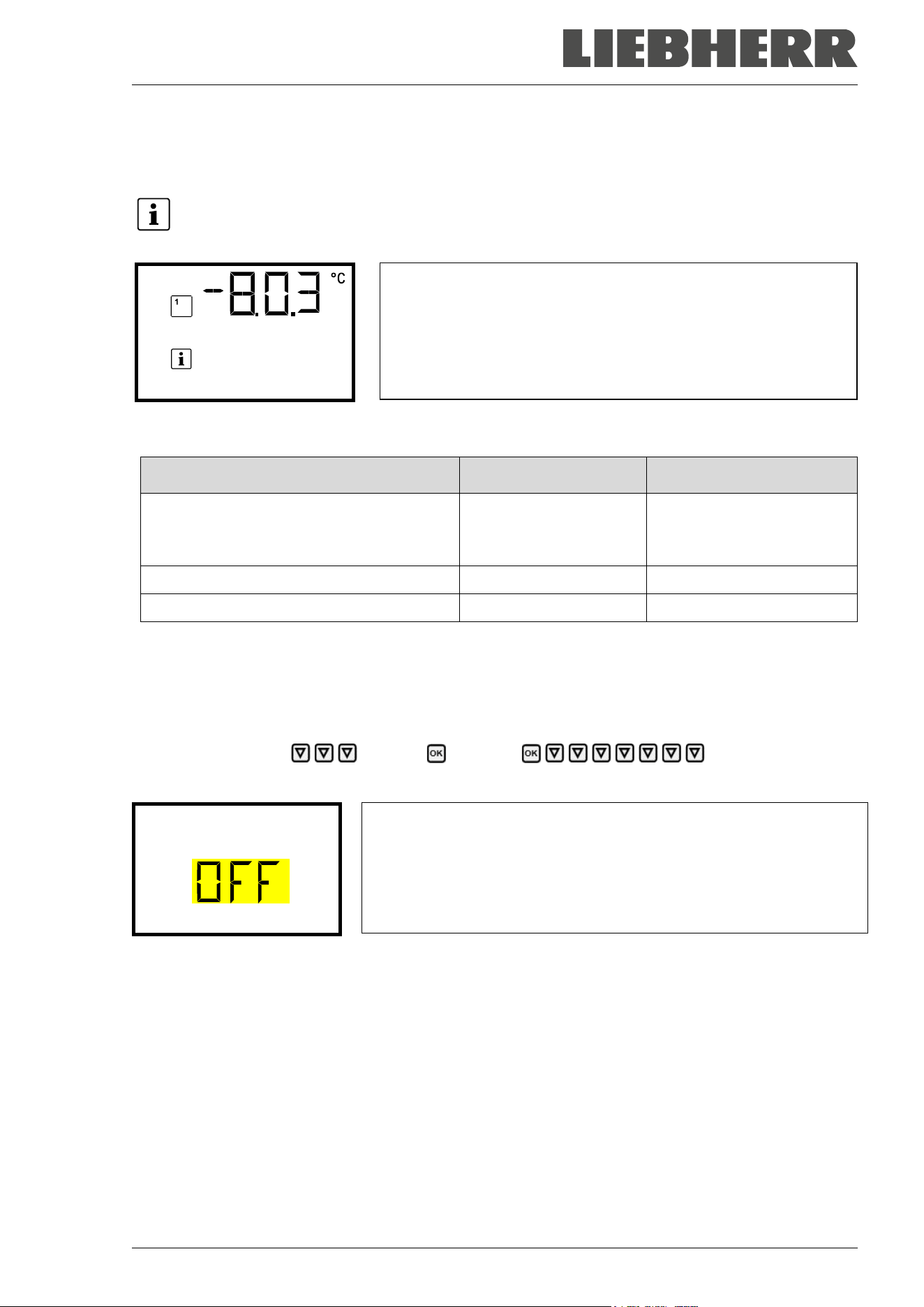
SUFsg 12/2024 Page 58/112
14.2 Information messages
Information messages provide information about settings made and the condition of the battery.
In Normal display a text message indicates the condition. The “Information” icon is lit.
Information message (example: CO
2
emergency cooling test run is
active)
CO2 cooling test activ
Information messages overview:
Condition Information message
Moment of information
message
Very low battery voltage (1 V to 11 V).
Low battery voltage on battery power.
Message on battery power and line power.
“Low battery voltage”
immediately
Service setpoint is active “Service setpoint active” immediately
Emergency cooling test run is active “CO2 cooling test active” immediately
14.3 Activating / deactivating the audible alarm (alarm buzzer)
Path: Normal display Settings Chamber Audible alarm
Press the OK button to enable the setting.
Setting the audible alarm.
The current setting flashes. Use the arrow buttons to select between
ON and OFF.
Confirm the setting with the OK button.
Audible alarm
With the Back button you can go back to the “Chamber” submenu and, repeatedly pressing it, to Normal
display.

SUFsg 12/2024 Page 59/112
14.4 Required actions in case of an alarm
Only qualified service personnel authorized by the manufacturer must perform repair.
Repaired chambers must comply with the manufacturer’s quality standards.
14.4.1 Safety controller temperature alarm
The selected temperature value of the safety controller was exceeded.
The alarm occurs immediately.
• Alarm message “Safety controller”, “collective alarm” icon
• Audible alarm (buzzer)
• Switching the zero-voltage relay alarm output
Actions:
• Check whether the outer door was open for a long time or is not closed properly. Close the door if
necessary. With open door there can be additional door open alarm.
• Check the setting of the safety controller (chap. 11). The limit temperature should be approx. by 15 K
above the temperature set point. If necessary, adjust the relevant value.
• Check whether samples were inserted into the freezer that may release heat.
• Check the ambient conditions. Protect the freezer from direct sunlight. Ensure sufficient ventilation
around the installation location to prevent any buildup of heat in the chamber.
• If these points do not reveal the source of the fault, it may be that the chamber is faulty. Please contact
the Service.
14.4.2 Temperature range alarm (too high and too low temperature)
The temperature range alarm becomes valid only after the setpoint has been reached.
When the actual temperature value leaves the alarm limit of the range alarm, the alarm occurs after the
defined delay time (chap. 13). Factory setting: 60 minutes.
• Alarm message “Temp. range”, “collective alarm” icon
• Audible alarm (buzzer)
• Switching the zero-voltage relay alarm output
Actions:
• Factory setting is +/- 5 K.
• Use the actual temperature displayed on the controller to verify whether the alarm limit of the range
alarm has been breached, i.e., too cold or too warm.
Temperature too low (under temperature alarm):
• Input of large quantities of samples which were precooled with liquid nitrogen. Reset the alarm with the
OK button.
• Possible cause: Continuous operation of the refrigeration machine after failure of one or several tem-
perature sensors (chap. 14.4.6). In addition, there is continuous operation alarm. Contact the Service.
SUFsg 12/2024 Page 60/112
Temperature too high (over temperature alarm):
• Check whether the outer door was open for a long time or is not closed properly. Close the door if
necessary. In addition, there is door open alarm.
• Check the door gaskets for damage. Replace any damaged gaskets.
• Check whether there is icing around the gaskets. Defrost, if necessary.
• Check whether samples were inserted into the freezer that may release heat.
• Check the ambient conditions. Protect the freezer from direct sunlight. Ensure sufficient ventilation
around the installation location to prevent any buildup of heat in the chamber.
• If these points do not reveal the source of the fault, it may be that the chamber is faulty. Please contact
the Service.
If the same alarm recurs, please contact the Service.
14.4.3 Door open alarm
The open and closed condition of the chamber door is controlled via the door contact switch. The temper-
ature rises when the door is opened causes the refrigerating machine to turn on.
When the door is opened the alarm occurs after the defined delay time (chap. 13), factory setting: 1 minute.
• Alarm message “Door open”, “collective alarm” icon
• Audible alarm (buzzer)
• Switching the zero-voltage relay alarm output
Actions:
• Close the outer door.
• Use the OK button to switch off the buzzer even when the door is open.
• The alarm message is cancelled.
• The zero-voltage relay alarm output switches off.
14.4.4 Power failure alarm
• No alarm message (display is off)
You can turn on the display with the OK button. It turns off automatically after 10 seconds.
• Audible alarm (buzzer): immediately
• Switching the zero-voltage relay alarm output.
WARNING: If customer should use a chamber running in non-supervised continuous opera-
tion, we strongly recommend in case of inclusion of irrecoverable specimen or samples to
split such specimen or samples and store them in at least two chambers, if this is feasible.

SUFsg 12/2024 Page 61/112
14.4.5 Messages on the battery management system
The alarms and information messages occur immediately.
Battery operation
• Alarm message “Battery operation”, “collective alarm” icon
• Audible alarm (buzzer)
• Switching the zero-voltage relay alarm output
• The message occurs on battery power (during power failure) after pressing the OK button (see chap.
10.3)
There is sufficient battery voltage.
Battery missing, completely empty (< 3V) or defective.
• Alarm message “Battery defective”, “collective alarm” icon
• Audible alarm (buzzer)
• Switching the zero-voltage relay alarm output
The message occurs on line power when no battery has been recognized.
Actions:
• With defective battery: replace battery.
• Reset alarm message. It will not reset automatically.
Low battery voltage
Information message “Low battery voltage”, “Information” icon
The message occurs on battery power and line power.
Battery voltage is very low (< 12 V). If this message lasts for more than 2 hours, the battery can be defective.
Actions:
• Check the power supply.
• Check the charging voltage in the controller menu (chap. 18.2)
• With defective battery: replace battery. Contact the Service.
• Reset alarm message. It will not reset automatically.

SUFsg 12/2024 Page 62/112
14.4.6 Messages referring to temperature sensor failure
The alarms occur immediately.
• Audible alarm (buzzer)
• Switching the zero-voltage relay alarm output
Failure of the temperature sensor for interior measurement:
• Alarm message “Inner temp. sensor”, “collective alarm” icon
• Cause: defective inner temperature sensor
• Temperature control continues using the safety controller temperature sensor
Failure of the safety controller temperature sensor:
• Alarm message “Safety control sensor”, “collective alarm” icon
• Cause: defective safety controller temperature sensor
Failure of both the temperature sensors for interior measurement and the safety controller:
• Temperature display shows “ - - - - “ or “ <-<-<“ or “ >->->“
• Alarm messages “Inner temp. sensor” and “Safety control sensor” alternating, “collective alarm” icon
• Cause: both the temperature sensors for interior measurement and the safety controller are defective
• Refrigeration is turned on permanently.
Failure of temperature sensors of the refrigerating machine:
• Alarm message “Condensate temp. sensor”, “collective alarm” icon
Cause: defective temperature sensor on the condenser of the refrigerating machine
• Alarm message “Cascade temp. sensor”, “collective alarm” icon
Cause: defective temperature sensor on the cascade of the refrigerating machine
If this sensor fails, refrigeration is turned on permanently
• Alarm message “Ambient temp. sensor”, “collective alarm” icon
Cause: defective temperature sensor for ambient temperature or air intake of the 1
st
stage cooling
Actions:
• Please contact the Service.
• If the temperature rises, i.e. the refrigerating machine is defective (safety controller temperature alarm
and / or temperature range alarm):
• Transfer the material to another freezer.
• Turn off the freezer.
• If necessary, clean and disinfect the freezer.
SUFsg 12/2024 Page 63/112
14.4.7 Messages referring to CO
2
emergency cooling (option CO
2
emergency cooling)
The alarms and information messages occur immediately.
CO
2
emergency cooling is activated
• No message, icon for function 1 is shown (chap. 20.3.2)
CO
2
emergency cooling is running (test run)
Information message “CO2 cooling test active”, information icon
Cause: CO
2
emergency cooling test run has been activated in the controller (chap. 20.3.3)
Actions:
If desired, deactivate CO
2
emergency cooling test run in the controller (chap. 20.3.3)
CO
2
emergency cooling is running (power failure)
• Alarm message “CO2 emergency cooling”, collective alarm icon
• Audible alarm (buzzer)
• Switching the zero-voltage relay alarm output
Cause: Power failure. Activated CO
2
emergency cooling automatically turned on and is running.
Insufficient CO
2
supply of the CO
2
emergency cooling system
• Alarm message “CO2 pressure”, collective alarm icon
• Audible alarm (buzzer)
• Switching the zero-voltage relay alarm output
Cause: emergency cooling has been activated, CO
2
connection pressure is too low.
Actions:
• Check if the CO
2
gas supply is open
• Connect a new pressurized CO
2
cylinder
It is not possible to determine the filling level of a pressurized CO
2
cylinder from the cylinder
pressure. Weigh the bottle regularly in order to replace it in time
Low battery voltage during CO
2
emergency cooling with battery operation
• Information message “Low battery voltage”, information icon.
• Battery voltage is very low (< 12 V).
Actions:
• Check the battery connections
• Charge the battery (charging mode: current, approx. 160 mA)
• If it is defective, replace the battery. Contact the Service.
• Reset the alarm message.
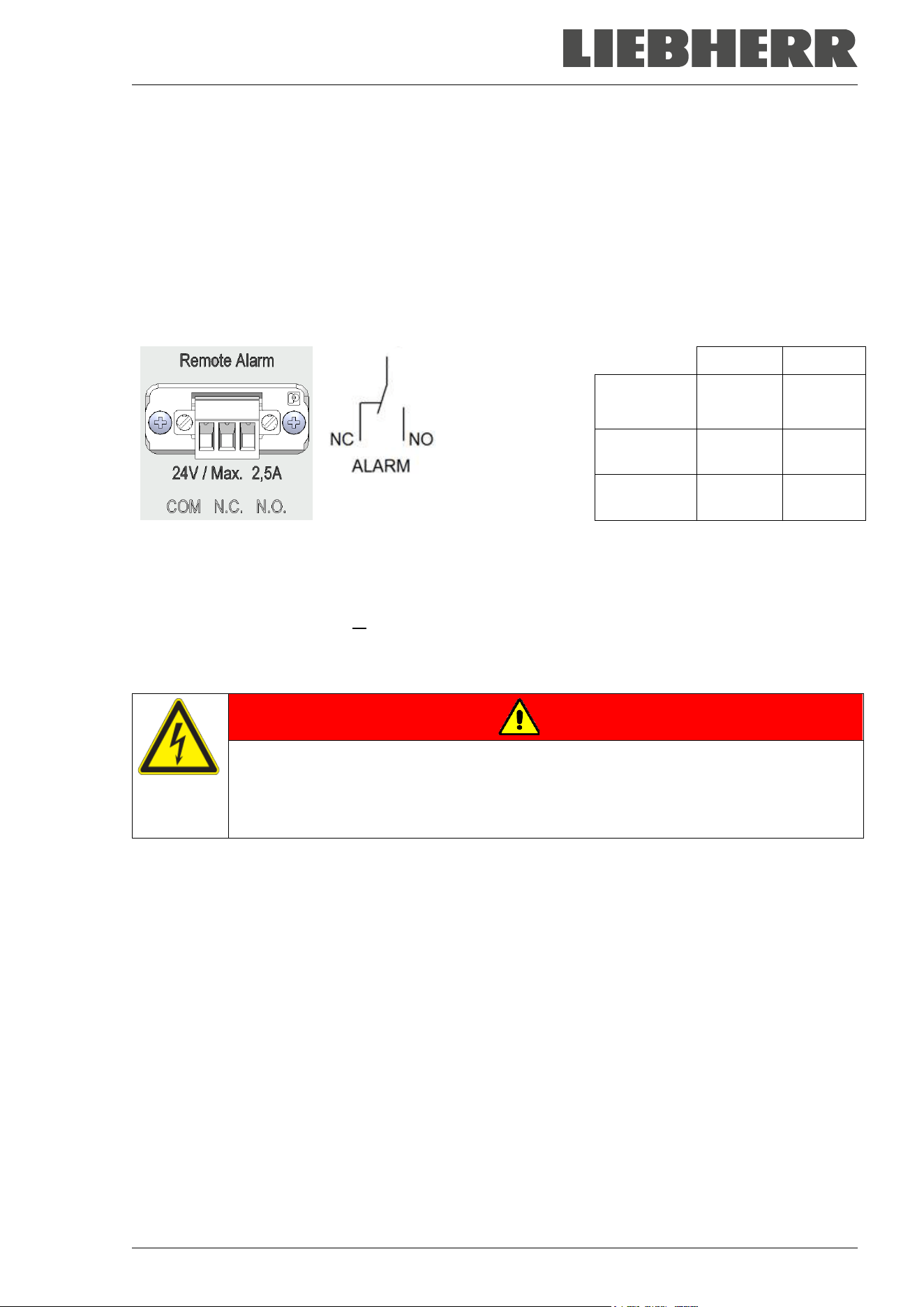
SUFsg 12/2024 Page 64/112
14.5 Zero-voltage relay alarm output
Collective alarm output via the zero-voltage relay alarm contact
The SUFsg freezer is equipped at the rear with a zero-voltage relay output (9), which permits the transmis-
sion of alarms to an external monitoring system in order to monitor and record the alarm signals.
The zero-voltage relay alarm output switches immediately, as soon as the “Collective alarm” icon lights up.
The zero-voltage relay alarm output switches for all alarm instances and in case of a power failure.
If the external alarm monitor is connected via the contacts COM and NO, alarm monitoring will take place
with protection against short-circuiting, i.e., if the connection between the freezer and the external alarm
monitor is interrupted, an alarm is triggered. In this case, power failure will also trigger the alarm.
COM = Pin 1
NC = Pin 2
NO = Pin 3
COM-NC COM-NO
SUFsg on,
no alarm
0 1
SUFsg on,
active alarm
1 0
SUFsg off 1 0
Figure 18: Zero-voltage contacts circuit diagram and pin allocation of the socket (9)
When the chamber is running and there is no alarm, contact COM closes with contact NO.
When the chamber is turned off or if there is an active alarm, contact COM closes with contact NC.
Closing contact COM with contact NC switches the zero-voltage relay alarm output.
Maximum loading capacity of the switching contacts: 24V AC/DC – 2.0 Amp.
DANGER
Electrical hazard through overload of switching contacts.
Deadly electric shock, damage to switching contacts and connection socket.
∅ Do NOT exceed the maximum switching load of 24V AC/DC – 2.0 Amp.
∅ Do NOT connect any devices with a higher loading capacity.
The alarm message on the controller display remains displayed during transmission of an alarm via the
zero-voltage relay outputs. As soon as the cause of the alarm is rectified, or the alarm message has been
reset, the alarm transmission via the zero-voltage relay outputs is reset together with the alarm message
on the controller display.
In case of power failure, transmission of the alarm via zero-voltage relay outputs remains active for the
duration of the power failure. Afterwards, the contact closes automatically.
Connection to an external monitoring system
To ensure short-circuit-proof alarm monitoring that will trigger the alarm when the freezer is connected to
an external alarm monitor, connect the external alarm monitoring system to the freezer via the connection
socket (9) of the zero-voltage relay output.
COM
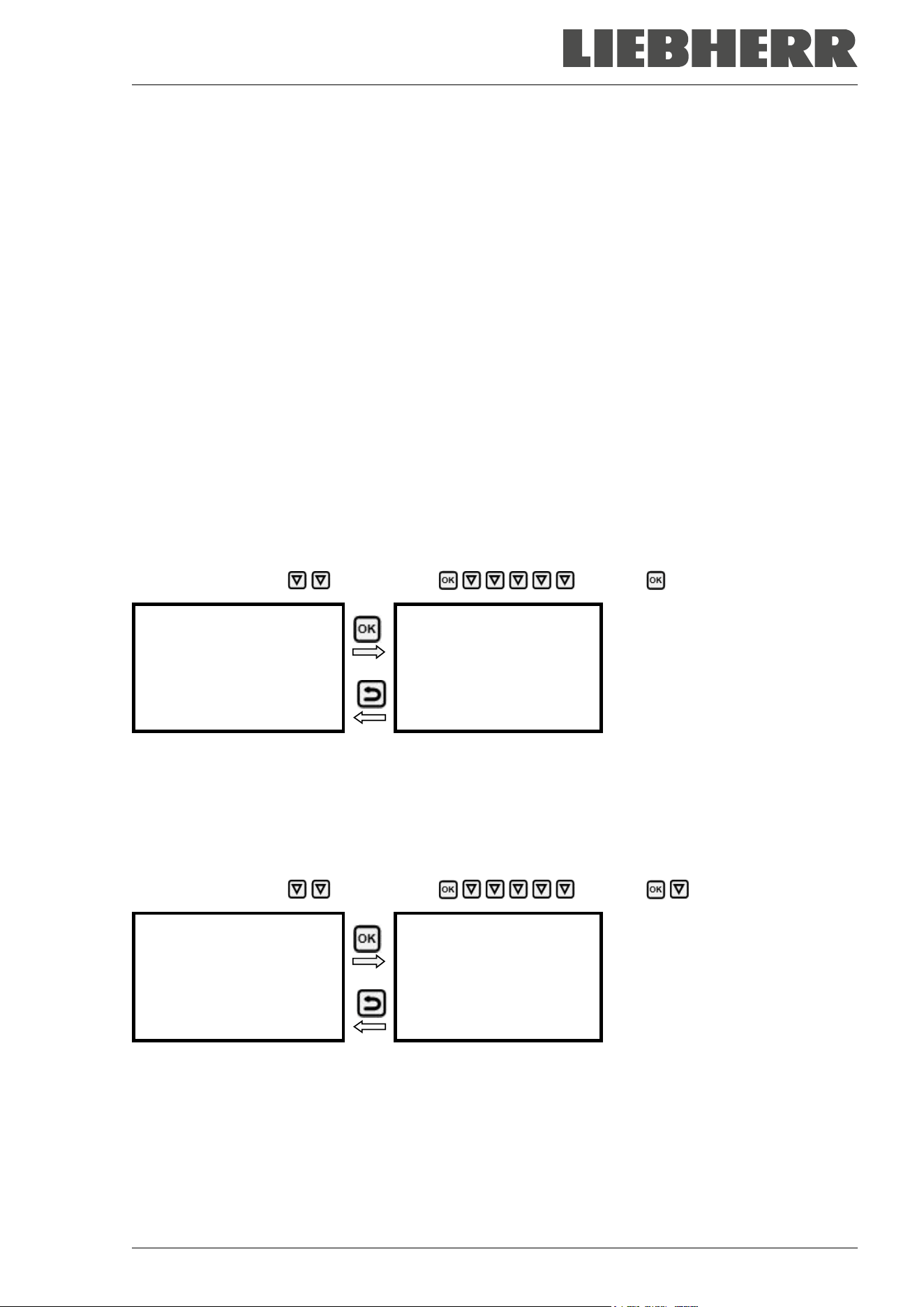
SUFsg 12/2024 Page 65/112
15. Ethernet network settings
The settings of this submenu are used for networking chambers with an Ethernet interface, e.g. to connect
them with a computer.
15.1 Showing the network settings
Required access level: “User”.
The “Ethernet” submenu offers to subsequently or individually access the following information:
• MAC address
• IP address
• Subnet mask
• Standard gateway
• DNS server address
• DNS chamber name
15.1.1 Showing the chamber’s MAC address
Path: Normal display Chamber info Ethernet MAC address
Display of the MAC address (exam-
ple)
Toggle forth and back with the Back
button and the OK button.
MAC address
00:00:00:00:00:00
With the arrow-down button you can now change to the next parameter (IP address).
With the Back button you can go back to the “Ethernet” submenu and, repeatedly pressing it, to Normal
display.
15.1.2 Showing the IP address
Path: Normal display Chamber info Ethernet IP address
Display of the IP address (example)
Toggle forth and back with the Back
button and the OK button.
IP address
0.0.0.0
With the arrow-down button you can now change to the next parameter (subnet mask).
With the Back button you can go back to the “Ethernet” submenu and, repeatedly pressing it, to Normal
display.
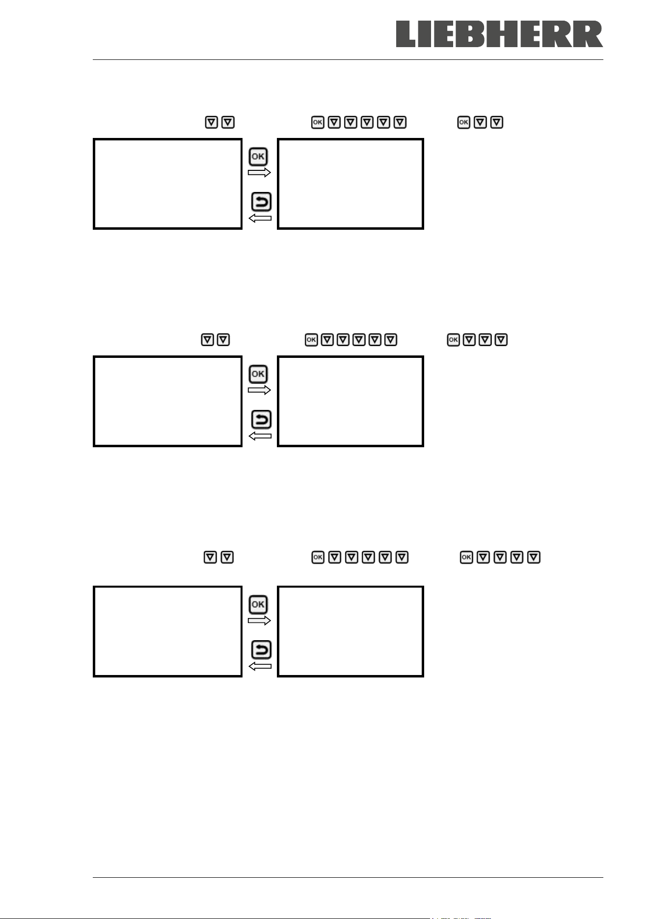
SUFsg 12/2024 Page 66/112
15.1.3 Showing the subnet mask
Path: Normal display Chamber info Ethernet Subnet mask
Display of the subnet mask (exam-
ple)
Toggle forth and back with the Back
button and the OK button.
Subnet mask
0.0.0.0
With the arrow-down button you can now change to the next parameter (standard gateway).
With the Back button you can go back to the “Ethernet” submenu and, repeatedly pressing it, to Normal
display.
15.1.4 Showing the standard gateway
Path: Normal display Chamber info Ethernet Standard gateway
Display of the standard gateway (ex-
ample)
Toggle forth and back with the Back
button and the OK button.
Standard gateway
0.0.0.0
With the arrow-down button you can now change to the next parameter (DNS server address).
With the Back button you can go back to the “Ethernet” submenu and, repeatedly pressing it, to Normal
display.
15.1.5 Showing the DNS server address
Path: Normal display Chamber info Ethernet DNS server
address
Display of the DNS server address
(example)
Toggle forth and back with the Back
button and the OK button.
DNS server address
0.0.0.0
With the arrow-down button you can now change to the next parameter (DNS chamber name).
With the Back button you can go back to the “Ethernet” submenu and, repeatedly pressing it, to Normal
display.
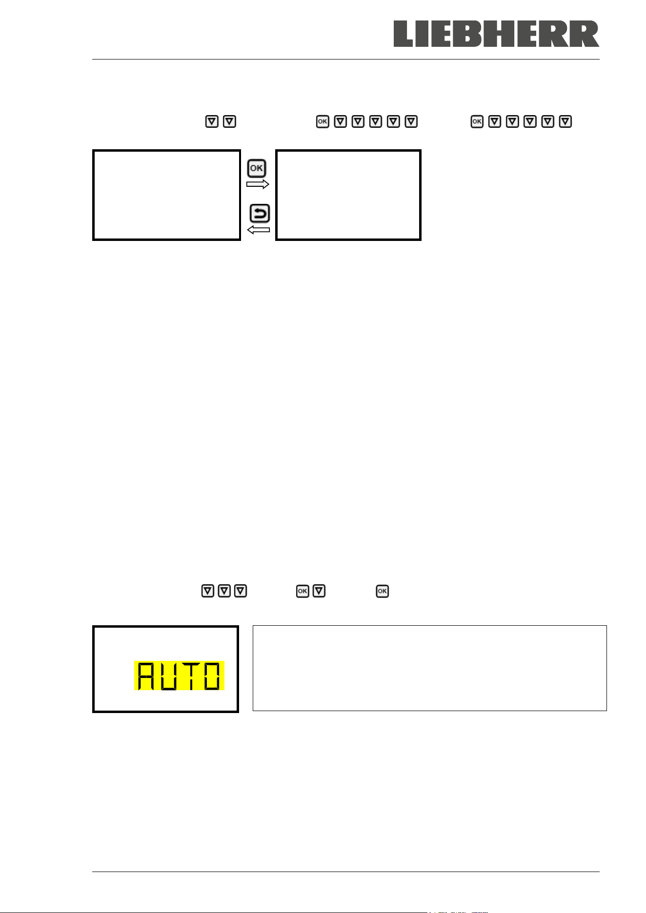
SUFsg 12/2024 Page 67/112
15.1.6 Showing the DNS chamber name
Path: Normal display Chamber info Ethernet DNS
chamber name
Display of the DNS chamber name
(example)
Toggle forth and back with the Back
button and the OK button.
DNS chamber name
000cd80a281
With the Back button you can go back to the “Ethernet” submenu and, repeatedly pressing it, to Normal
display.
15.2 Changing the configuration of the network settings
Required access level: “Admin”.
The “Ethernet” submenu offers to subsequently or individually access the following settings:
• Selecting the type of assignment (automatic or manual) of the IP address, chap. 15.2.1
If automatic IP address assignment has been selected:
• Selecting the type of assignment (automatic or manual) of the DNS server address, chap. 15.2.2
If manual IP address assignment has been selected:
• Assigning the IP address, chap. 15.2.3
• Assigning the subnet mask, chap. 15.2.4
• Assigning the standard gateway, chap. 15.2.5
If manual IP address assignment or manual DNS server address assignment has been selected:
• Assigning the DNS server address, chap. 15.2.6
15.2.1 Selecting the type of IP address assignment (automatic / manual)
Path: Normal display Settings Ethernet IP address assignment
Press the OK button to enable the setting
Selection of the type of assignment of the IP address.
The current setting flashes. Use the arrow buttons to select between
AUTO (automatic) and MANU (manual).
Confirm the setting with the OK button.
IP address assignmen
With the arrow-down button you can now change to the next parameter.
• If manual IP address assignment has been selected: assign the IP address (chap. 15.2.3)
• If automatic IP address assignment has been selected: select the type of assignment of the DNS server
address (chap. 15.2.2).
With the Back button you can go back to the “Ethernet” submenu and, repeatedly pressing it, to Normal
display.
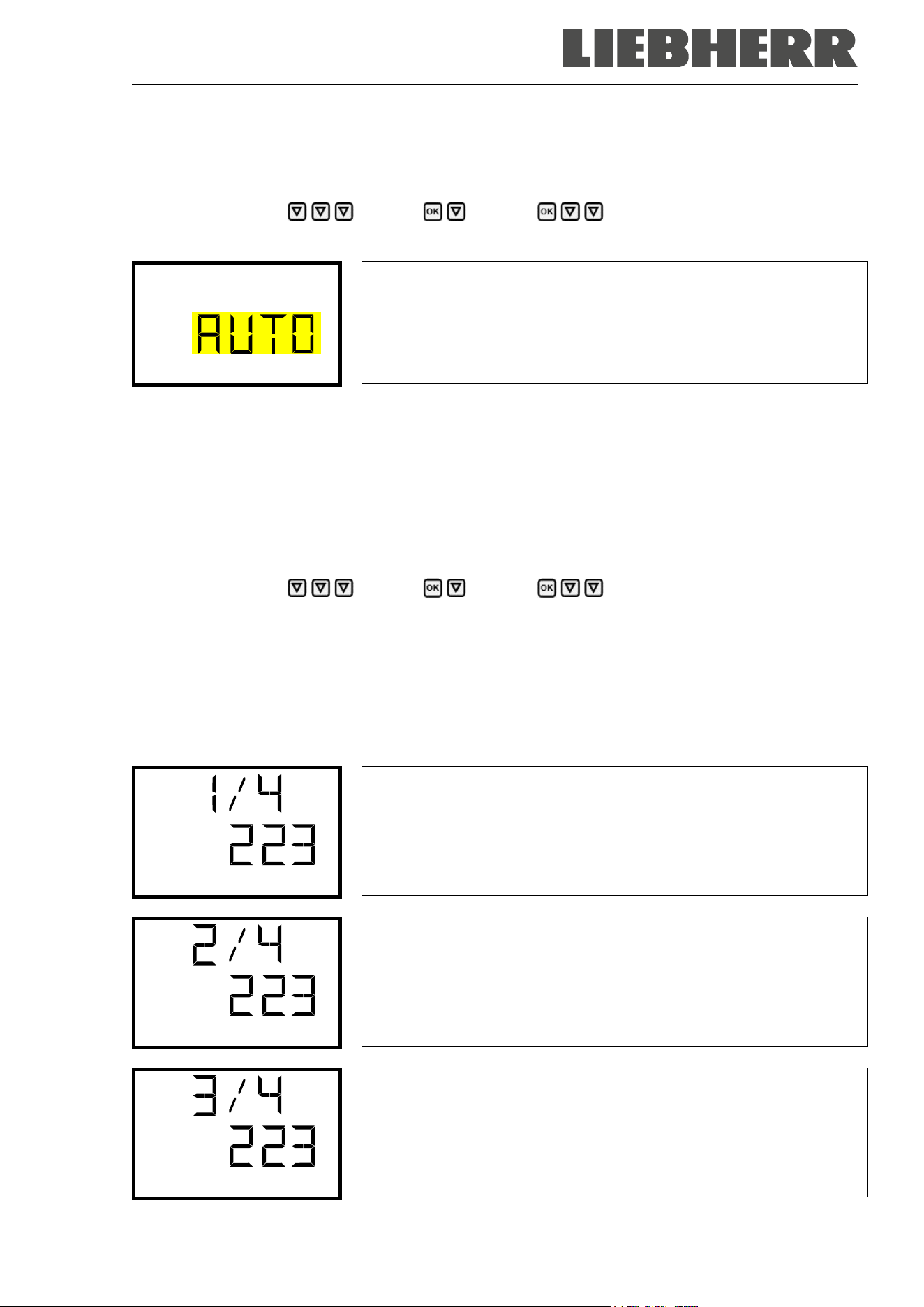
SUFsg 12/2024 Page 68/112
15.2.2 Selecting the type of assignment of the DNS server address (automatic / manual)
Access to this function is possible only if automatic IP address assignment has been selected (chap.
15.2.1).
Path: Normal display Settings Ethernet DNS server
Press the OK button to enable the setting.
Selection of the type of assignment of the DNS server address.
The current setting flashes. Use the arrow buttons to select between
AUTO (automatic) and MANU (manual).
Confirm the setting with the OK button.
DNS server
If manual assignment of the DNS server address has been selected, you can now change with the arrow-
down button to assign the DNS server address (chap. 15.2.6).
With the Back button you can go back to the “Ethernet” submenu and, repeatedly pressing it, to Normal
display.
15.2.3 Assigning the IP address
Access to this function is possible only if manual IP address assignment has been selected (chap. 15.2.1)
Path: Normal display Settings Ethernet IP address
Press the OK button to enable the setting.
The IP address entry is done in four steps, corresponding to the number sections: (1).(2).(3).(4)
Principle of entry:
• Use the OK button to select the desired section of the IP address 1/4, 2/4, 3/4, 4/4 in the upper display
line
• Use the Arrow buttons to enter the value for the selected section of the IP address
IP address assignment (sample values).
The first section of the IP address is shown. Enter the desired value with
the arrow buttons.
Use the OK button to confirm the entry and proceed to the second sec-
tion of the IP address.
IP address
IP address assignment (sample values).
The second section of the IP address is shown. Enter the desired value
with the arrow buttons.
Use the OK button to confirm the entry and proceed to the third section
of the IP address.
IP address
IP address assignment (sample values).
The third section of the IP address is shown. Enter the desired value
with the arrow buttons.
Use the OK button to confirm the entry and proceed to the last section
of the IP address.
IP address
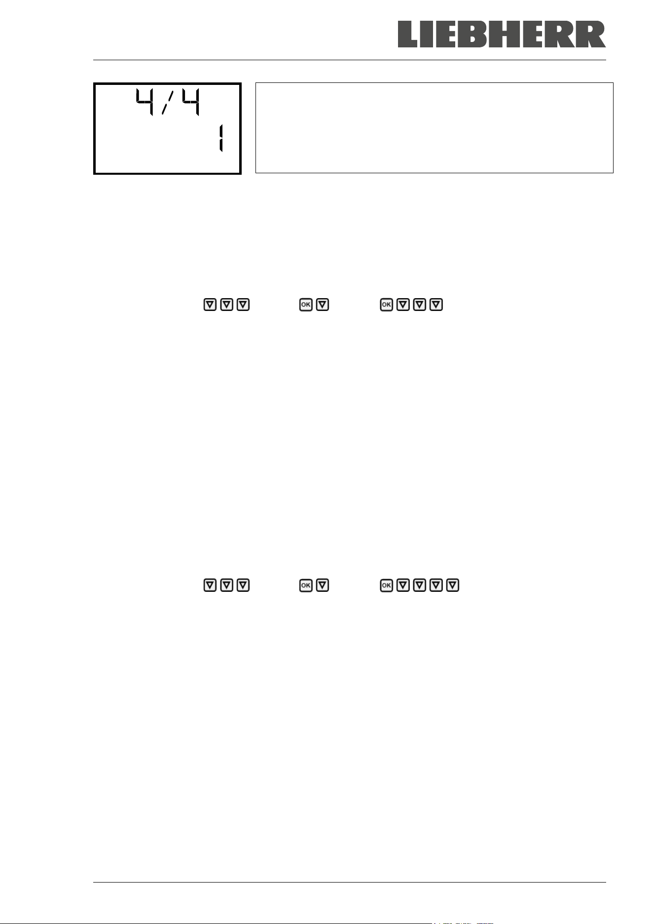
SUFsg 12/2024 Page 69/112
IP address assignment (sample values).
The forth section of the IP address is shown. Enter the desired value
with the arrow buttons.
Confirm the setting with the OK button.
IP address
With the arrow-down button you can now change to the enter the subnet mask.
With the Back button you can go back to the “Ethernet” submenu and, repeatedly pressing it, to Normal
display.
15.2.4 Setting the subnet mask
Access to this function is possible only if manual IP address assignment has been selected (chap. 15.2.1)
Path: Normal display Settings Ethernet Subnet mask
Press the OK button to enable the setting.
The subnet mask entry is done in four steps, corresponding to the number sections: (1).(2).(3).(4)
Principle of entry:
• Use the OK button to select the desired section of the subnet mask 1/4, 2/4, 3/4, 4/4 in the upper display
line
• Use the Arrow buttons to enter the value for the selected section of the subnet mask
For details please refer to the description of the similar procedure in chap. 15.2.3 “Assigning the IP ad-
dress”.
With the arrow-down button you can now change to the enter the standard gateway.
With the Back button you can go back to the “Ethernet” submenu and, repeatedly pressing it, to Normal
display.
15.2.5 Setting the standard gateway
Access to this function is possible only if manual IP address assignment has been selected (chap. 15.2.1)
Path: Normal display Settings Ethernet Standard gateway
Press the OK button to enable the setting.
The standard gateway entry is done in four steps, corresponding to the number sections: (1).(2).(3).(4)
Principle of entry:
• Use the OK button to select the desired section of the standard gateway 1/4, 2/4, 3/4, 4/4 in the upper
display line
• Use the Arrow buttons to enter the value for the selected section of the standard gateway
• For details please refer to the description of the similar procedure in chap. 15.2.3 “Assigning the IP
address”.
With the arrow-down button you can now change to the assign the DNS server address.
With the Back button you can go back to the “Ethernet” submenu and, repeatedly pressing it, to Normal
display.

SUFsg 12/2024 Page 70/112
15.2.6 Assigning the DNS server address
Access to this function is possible if manual IP address assignment (chap. 15.2.1) or manual DNS server
address assignment (chap. 15.2.2) has been selected.
With manual IP address assignment:
Path: Normal display Settings Ethernet DNS server address
With manual DNS server address assignment:
Path: Normal display Settings Ethernet DNS server address
Press the OK button to enable the setting.
The DNS server address entry is done in four steps, corresponding to the number sections: (1).(2).(3).(4)
Principle of entry:
• Use the OK button to select the desired section of the DNS server address 1/4, 2/4, 3/4, 4/4 in the
upper display line
• Use the Arrow buttons to enter the value for the selected section of the DNS server address
• For details please refer to the description of the similar procedure in chap. 15.2.3 “Assigning the IP
address”.
With the Back button you can go back to the “Ethernet” submenu and, repeatedly pressing it, to Normal
display.
16. Data recorder
An internal data recorder saves chamber data and events in three data sets.
With the export function “Export recorder data” (chap. 17.3) you can save the three data sets via the USB
interface to USB stick. They are issued in the selected language as a spreadsheet with the file extension
“.csv” and can be further processed in the desired program. The data is unencrypted. Always the entire
data memory is read out.
16.1 Recorded data
All data is given out in tabular form. The headlines of the values “number”, “date”, and “time” are given out
in the selected language, all other information in English.
• Chamber data for the user “DL1”
Tabular representation of the actual temperature value and temperature set-point together with the date
and time, according to the set storage rate (chap. 16.3). Temperature values are always given out in °C.
• Chamber data for the manufacturer’s Service “DL2”
This data is intended for use by the manufacturer’s Service. The storage rate is fix (1 minute). Temper-
ature values are always given out in °C.
• Event list
Messages regarding the controller and data memory as well as the alarm messages together with the
date and time:
• Firmware update done
• “New config (USB)”: New configuration uploaded via USB
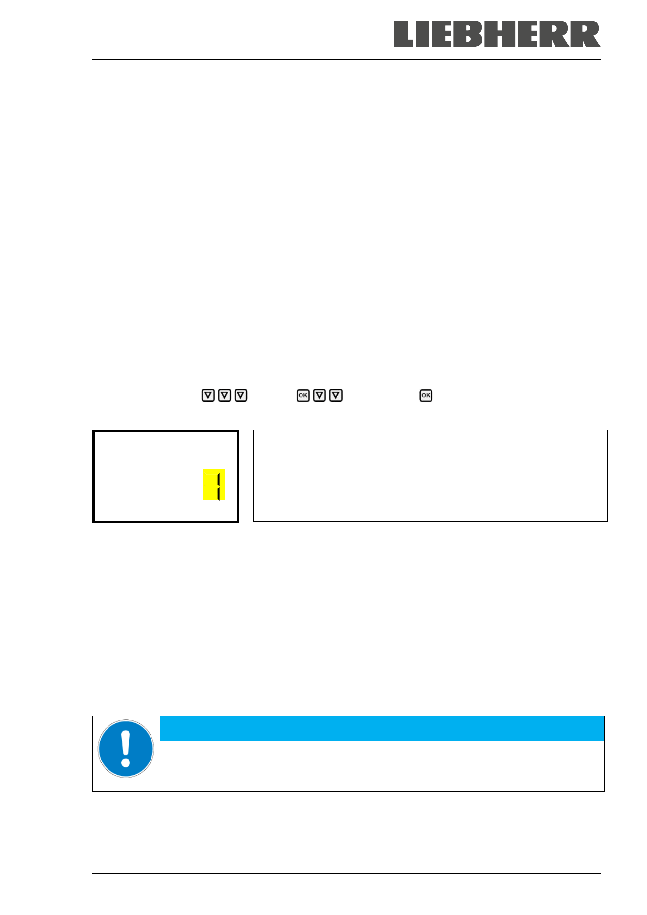
SUFsg 12/2024 Page 71/112
• “Data recorder cleared”: Data recorder and event list deleted via setup program
• Other event messages according to existing alarms
The moment of switching the alarm state on and off is indicated under “On/Off”.
16.2 Storage capacity
The storage capacity of the data recorder depends on the number of entries.
• DL1 = 110.000 entries (equaling 76 days with a storage rate of 1 minute, setting see chap. 16.3)
• DL2 = 27.000 entries (equaling 18 days with a fix storage rate of 1 minute)
• Event list: 200 events
The shorter the set storage rate, the closer are the stored measuring points, the more precise, but also
shorter is the documented period.
Once the storage capacity of the data recorder is reached, overwriting of the oldest values begins
16.3 Setting the storage rate for the “DL1” recorder data
Required access level: “Admin”.
Path: Normal display Settings Data recorder Storage interval
Press the OK button to enable the setting.
Function “Storage interval”.
The current setting flashes. Use the arrow buttons to enter the desired
storage interval. Setting range: 1 minute (factory setting) to 60 minutes.
Press the OK button to confirm the setting.
Storage interval
With the Back button you can go back to the “Data recorder” submenu and, repeatedly pressing it, to
Normal display.
16.4 Deleting the data recorder
When importing a configuration via USB stick and when loading a new firmware version by the service, the
entire data memory is deleted.
The service can also install the configuration by means of a setup program without deleting the data.
Regardless of this, the manufacturer’s Service can delete the data via a setup program.
Loading a new configuration via USB stick leads to deleting the data recorder.
NOTICE
Danger of information loss when loading a new configuration via USB stick.
Data loss.
Backup data before loading a new configuration via USB stick.
SUFsg 12/2024 Page 72/112
17. USB-Menu: Data transfer via USB interface
A USB interface for data transfer via USB stick is located in the door lock and controller housing (the second
micro USB interface is only used by the manufacturer).
The controller offers an import function and three export functions through the USB interface:
Import function (chap. 17.2):
• Configuration data in file “KONF380.set”
Export functions (chap. 17.3):
• Configuration data in file “KONF380.set”
• Recorder data
- DL1 (chamber data for the user): “DL1_[MAC address of the chamber].csv”
- DL2 (chamber data for the manufacturer’s Service): “DL2_[ MAC address of the chamber].csv”
- Event list: “EvList_[MAC address of the chamber].csv”
For detailed information on the file content see chap. 16.1.
• Service data
The "Service" folder is created on the USB stick and can be sent to the manufacturer’s Service. In
addition to the configuration and recorder data, it contains further service-relevant information.
17.1 Connecting the USB stick
Connect the USB stick to the interface located in the controller housing.
Connect only USB sticks to the USB interface.
The USB stick must be formatted with FAT32 and have at least 8GB of memory.
After inserting the USB stick, the initial function “Import configuration” is displayed.
As long as the USB stick is connected, only the functions for data transfer are available. Other controller
functions are only available after removing the USB stick.
17.2 Import function
Required access level: “Admin”.
Function “Import configuration”.
To import configuration data from the USB stick, press the OK button.
Import configuration
With the arrow-down button you can now change to the setting of the “Export configuration” function.
SUFsg 12/2024 Page 73/112
17.3 Export functions
Required access level: any user
Function “Export configuration”.
To write the configuration data from the controller to the USB stick,
press the OK button.
Export configuration
With the arrow-down button you can now change to the next function.
Function “Export recorder data”.
To write the recorder data from the controller to the USB stick, press the
OK button.
Export recorder data
With the arrow-down button you can now change to the next function.
Function “Export service data”.
To write the chamber data from the controller to the USB stick, press the
OK button.
Export service data
17.4 Ongoing data transfer
A moving arrow symbol indicates the progress of the data transfer.
Example:
Data recording is running.
Export service data
Attention! Danger of data loss! Do not disconnect the USB stick from the chamber during ongoing data
transfer!
After successful transfer, the controller shows again the initial function “Import configuration”.
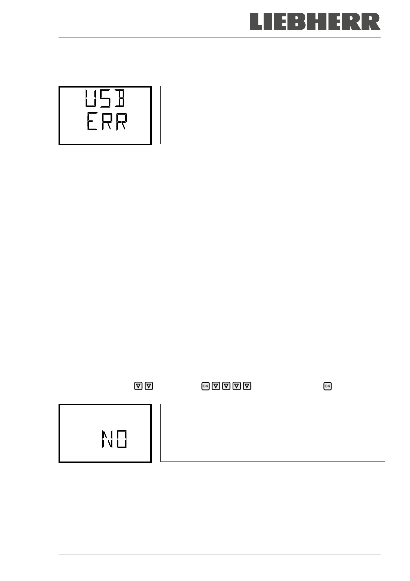
SUFsg 12/2024 Page 74/112
17.5 Error during data transmission
In the event of an error, the message ERR (error) is displayed.
Read error (example).
Import configuration
17.6 Removing the USB stick
Logging off the USB stick is not possible / required.
Be sure that no data recording is running (chap. 17.4).
After removing the USB stick, the controller is back in the same menu as before when connecting the USB
stick.
18. Battery management system
This controller menu serves to check whether the battery is present and which is its current charging state.
These are pure display functions without any setting options.
18.1 Battery operation
This menu shows whether the chamber voltage is supplied by the battery.
• Display “YES”: Battery operation (during power failure)
• Display “NO”: Battery is charging, external power connection available
If no battery is detected (battery is missing, completely empty (< 3V), or defective, on line power the
alarm message “Battery defective” is emitted (chap. 14.4.5).
Required access level: “User”.
Path: Normal display Chamber info Battery management Battery opera-
tion
Display “Battery operation”.
YES = Battery operation, no power connection available
NO = Battery charging, external power supply
Battery operation
With the arrow-down button you can now change to the function “Charging voltage”.
With the Back button you can go back to the “Battery management” submenu and, repeatedly pressing
it, to Normal display.
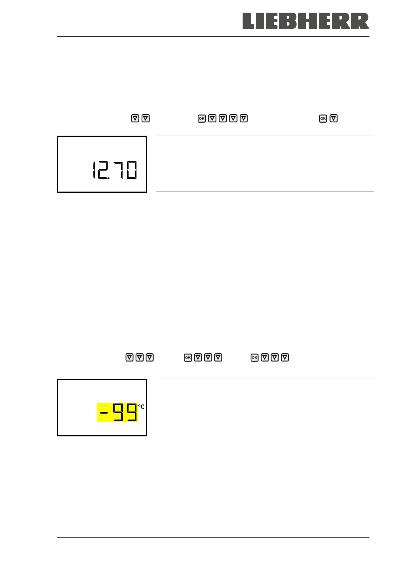
SUFsg 12/2024 Page 75/112
18.2 Charging voltage
This menu shows the battery’s current charging voltage. The correct voltage is > 12 V.
As soon as the charging voltage falls below the limit value of 12 V, the information message “Low battery
voltage” is emitted. This happens on battery power and line power (chap. 14.4.5).
Required access level: “User”.
Path: Normal display Chamber info Battery management Charging
voltage
Display of the battery’s current charging voltage.
Charging voltage
With the arrow-up button you can change to the function “Battery operation”.
With the Back button you can go back to the “Battery management” submenu and, repeatedly pressing
it, to Normal display.
19. Setting and activating the service setpoint
To set a lower setpoint value for test purposes or for adjustment, you can enter and activate a service
setpoint. This setting is outside the control range and is not intended for normal operation.
Once the service setpoint has been activated, the standard temperature setpoint will have no effect. Only
after deactivating the service setpoint, the chamber will equilibrate again to the standard temperature set-
point.
19.1 Setting the service setpoint
Required access level: “Admin”.
Path: Normal display Settings Various Service setpoint
Press the OK button to enable the setting.
Setting the service setpoint
The current setting flashes. Use the arrow buttons to enter the de-
sired value. Entry range: +20 °C up to -99 °C. Factory setting: -99 °C.
Confirm the setting with the OK button.
Service setpoint
With the arrow-up button you can go to setting the alarm limit for range alarm (chap. 13.3).
With the arrow-down button you can now change to the Manual Offset setting (chap. 7.1).
With the Back button you can go back to the “Various” submenu and, repeatedly pressing it, to Normal
display.
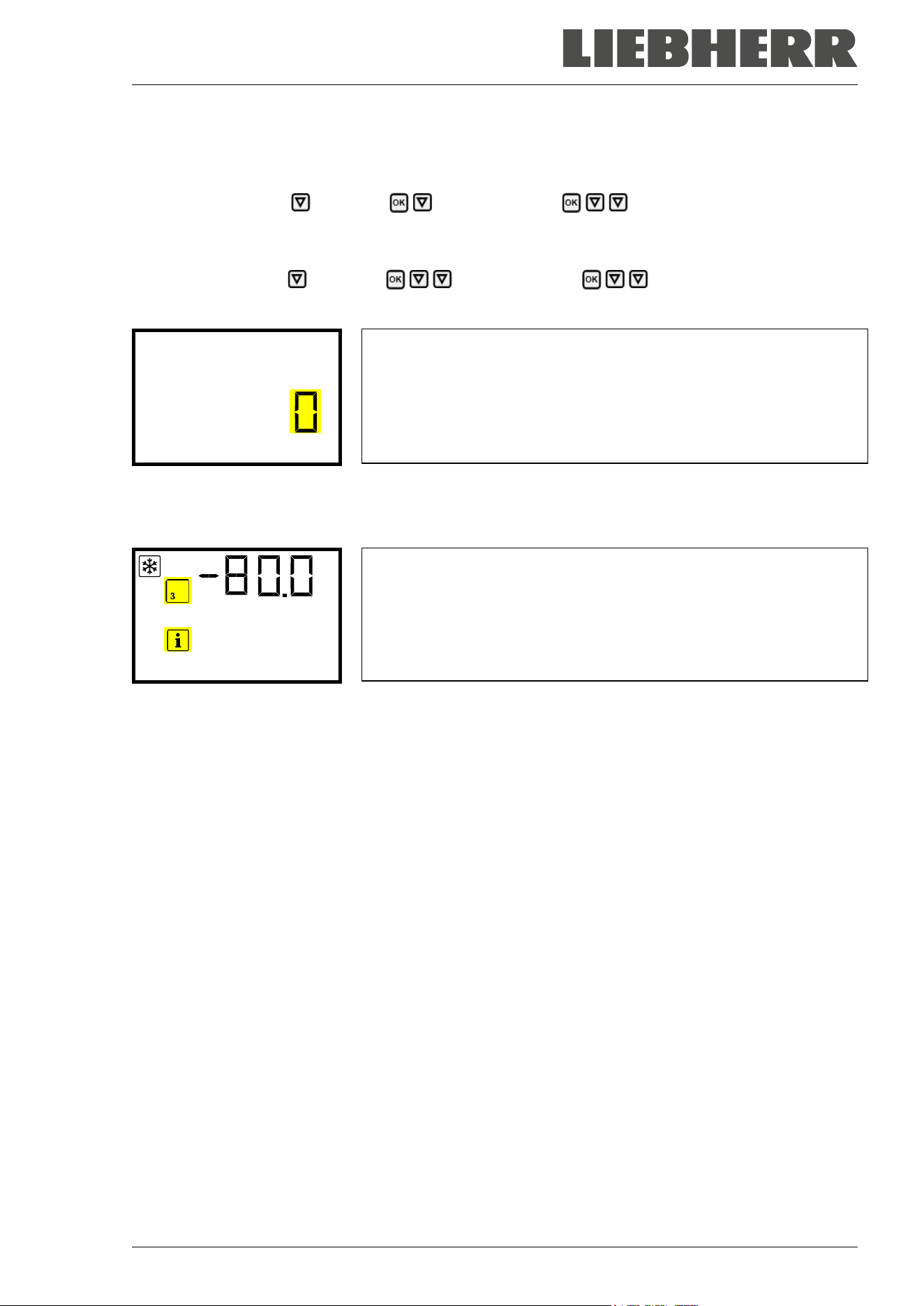
SUFsg 12/2024 Page 76/112
19.2 Activating the service setpoint
Required access level: “User”.
Path: Normal display Setpoints Functions on/off Service setpoint on/off
With optional CO
2
emergency cooling:
Path: Normal display Setpoints Functions on/off Service setpoint on/off
Press the OK button to enable the setting.
Setting function 3 “Service setpoint on/off”.
The current setting flashes. Use the arrow buttons to select between
“1” (Service setpoint active) and “0” (Service setpoint not active).
Confirm the setting with the OK button.
Service setpoint on/o
With the Back button you can go back to the “Functions on/off” submenu and, repeatedly pressing it, to
Normal display.
Normal display with the information message “Service setpoint active”.
Service setpoint acti
The service setpoint will remain active until manually deactivating function 3 “Service setpoint on/off”.
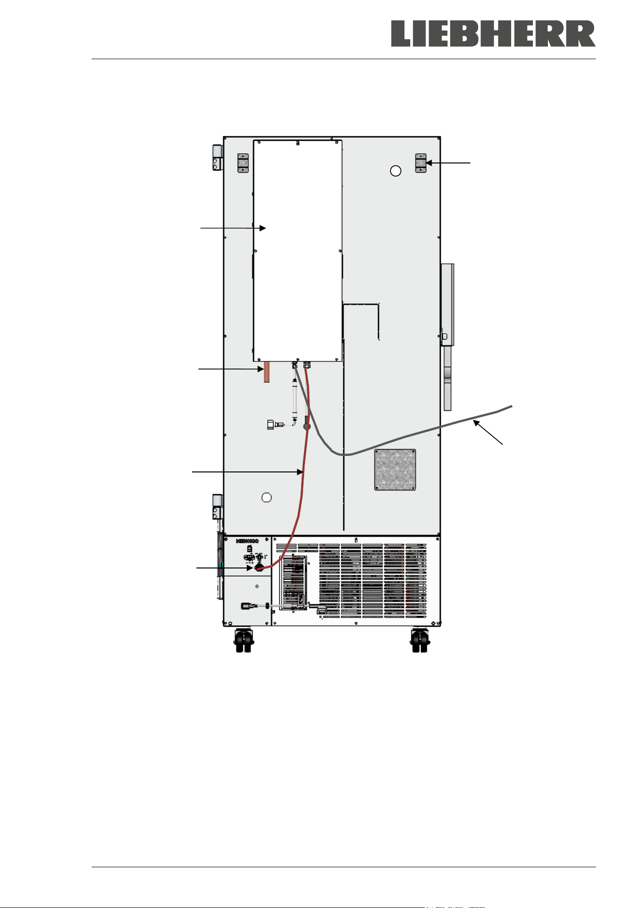
SUFsg 12/2024 Page 77/112
20. CO
2
emergency cooling (option for SUFsg 5001, SUFsg 7001)
Figure 19: Rear view of SUFsg with CO
2
emergency cooling system
(J) CO
2
emergency cooling
(11) Connection socket for the electrical connection of the CO
2
emergency cooling
(12) CO
2
discharge outlet to connect a discharge hose
(13) Cable to connection socket (11) for the electrical connection of the CO
2
emergency cooling
(14) Pressure compensation opening (visible from the inside). Here CO
2
will also escape.
(15) Gas hose to connect the pressurized CO
2
cylinders
(14)
(15)
(12)
(13)
(11)
(J)
SUFsg 12/2024 Page 78/112
Control and temperature measurement of the chamber controller are used for the CO
2
emergency cooling;
therefore, this option cannot be used for ultra-low temperature freezers from other manufacturers.
The optional CO
2
emergency cooling is intended only for the use with this ultra-low tempera-
ture freezer SUFsg.
The CO
2
emergency cooling offers additional refrigeration when the inner chamber temperature increased
up to the pre-set emergency cooling temperature. This may become necessary, following introduction of a
heat load, in case of a power failure or failure of the cooling system.
Principle: CO
2
is taken from the gas bottle in liquid form and introduced into the freezer when required.
There the gas expands and cools off intensely, forming a mixture of CO
2
gas and CO
2
snow. The CO
2
snow
provides the required cooling capacity through the transition into the gaseous state.
The emergency cooling system is integrated into the safety chain of the chamber. In case of power failure,
rechargeable batteries supply the CO
2
emergency cooling power supply, during normal operation power is
supplied by a power supply unit 24V DC. The rechargeable battery is designed for an interruption of the
external power supply of 72 hours maximum. Therefore, if pressurized CO
2
cylinders are available in suffi-
cient quantity, functioning of the CO
2
emergency cooling should last through a week-end.
You can set the CO
2
emergency cooling system between -40 °C / -40 °F and -70 °C / -94 °F. In order to
ensure an emergency cooling time as long as possible with a given CO
2
stock, select the highest possible
emergency cooling temperature.
The optional CO
2
emergency cooling system is available as a retrofit kit. Please contact the manufacturer’s
dealer.
The upper left 28 mm access port (6a) on the rear of the ultra-low temperature freezer serves
to connect the CO
2
emergency cooling.
20.1 Connecting and exchanging the pressurized CO
2
cylinder
The CO
2
emergency cooling system works exclusively with liquid CO
2
. Use CO
2
dip tube cylin-
ders with a W21.8 x 1 ¼ inch safety valve connection. The maximum ambient temperature for
the cylinder must not exceed 35 ° C. The dip tube inside enables almost complete liquid with-
drawal. CO
2
dip tube cylinders must stand upright during withdrawal.
Note regarding the installation site of the gas cylinder:
The cooling power decreases with increasing temperature of the liquid CO
2
. Do not install the gas cylinder
in the exhaust airflow of the ultra-low temperature freezer.
The supplied gas hose (15) is already connected with the CO
2
emergency cooling system. The user shall
not remove this connection. When replacing the gas hose is required, please contact the manufacturer’s
Service. To connect the pressurized CO
2
cylinder, connect the free end of the gas hose to the gas cylinder
(wrench size A/F 30 mm / 1.2 in). Then open the valve of the gas cylinder.
Before changing the gas cylinder, first close the valve of the empty gas cylinder. Perform a test run of the
CO
2
emergency cooling to reduce the CO
2
pressure in the emergency cooling system. Only then unscrew
the gas hose.
After connecting the gas cylinder, check the hose connection with a soap solution for gas
leaks. The hose connection must be tight
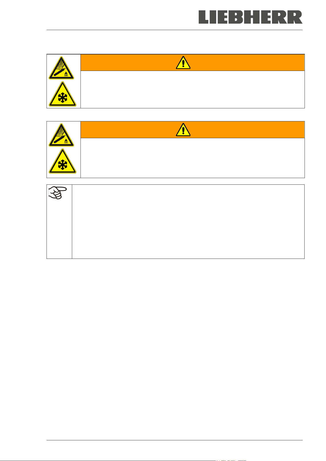
SUFsg 12/2024 Page 79/112
The valve of the gas cylinder always must be closed before screwing on or unscrewing the gas hose
WARNING
Risk of injury through sudden release of the stored pressure energy when opening
the cylinder valve of a not connected cylinder.
Injuries.
Close the gas cylinder valve before connecting or removing the gas hose.
Secure the pressurized gas cylinder against falling and other mechanical damage.
WARNING
Risk of injury through sudden release of the stored pressure energy when the valve
safety is torn off.
Injuries.
Secure gas cylinders against falling (chaining).
Transport gas cylinders with a cylinder cart.
General information for safe handling of pressurized CO
2
cylinder:
• Open the gas cylinder valve slowly to avoid pressure surges.
• Secure gas cylinders during storage and use against falling (chaining).
• Transport gas cylinders with a cylinder cart, do not carry, roll, or throw them.
• Always close the valve even with apparently empty cylinders; screw on the cap when not in
use. Return gas cylinders with the valve closed.
• Do not open gas cylinders by force. Mark them when damaged.
• Protect gas cylinders against fire, e.g. do not store together with flammable liquids.
• Observe relevant regulations for dealing with pressurized CO
2
cylinder.
Information for the operator concerning requirements and regulations for use of pressurized gas cylinders
in the laboratory (not exhaustive):
A storage of pressurized gas cylinder (stockholding, no connection for emptying, storing for later use or for
supply to others) in a laboratory without a storage cabinet is generally prohibited. The requirements for fire-
protected pressurized gas cylinder cabinets are described in DIN EN 14470-2:2006.
Provisioning (reserve cylinders connected to the points intended for emptying or provided for imminent
connection) and using (provisioning, operating, emptying) of pressurized gas cylinders may also take place
outside storage cabinets or storage rooms, provided that the safety requirements are met. This applies to
the operation of the CO
2
emergency cooling system.
• Observe all relevant local and national regulations, in particular the requirements for provisioning / emp-
tying the pressurized gas cylinders.
• If there are more than 6 cylinders in the laboratory, they must be placed in cylinder cabinets, special
installation rooms or outdoors. After work (freezer turned off) store the cylinders in a safe storage loca-
tion.
• Perform leakage tests
• Fire extinguishers must be available in order to protect the gas cylinders against heating in case of fire
SUFsg 12/2024 Page 80/112
• Make sure that operating instructions on the connection and exchange of the pressurized gas cylinders
are attached in the vicinity of the pressurized gas cylinders. The instructions shall contain all required
safety-related information in an intelligible form.
• Laboratories in which compressed gas cylinders are installed must be
labeled with the warning sign W019 “Warning of gas cylinders”.
• In areas with increased risk of fire, if possible set up gas cylinders outside the rooms and install fix
tubing.
Carbon dioxide (CO
2
) in high concentrations (> 4 Vol.-%) is hazardous to health. It is colorless and almost
odorless and therefore practically imperceptible. Escaping CO
2
gas is heavier than air and accumulates at
the ground or possibly in lower-lying parts of the building. There is danger of suffocation and poisoning.
Hazards due to uncontrolled gas release must be effectively avoided.
DANGER
Danger of suffocation and poisoning by high concentration of CO
2
(> 4 Vol.-%).
Death by suffocation.
∅ Operate the CO
2
emergency cooling only in a well-ventilated room.
Ensure technical ventilation measures. Install a suitable conduct at the CO
2
discharge
outlet of the emergency cooling system.
Observe the relevant regulations for handling CO
2
.
Close the CO
2
supply when decommissioning the chamber.
When installing pressurized CO
2
cylinders take into account the structure of the building.
• The installation site must be in a well-ventilated area (natural ventilation). For rooms with a with a floor
area of ≤ 12 m
2
with solid walls without openings on all sides there are further regulations (max. two 14-
liter CO
2
cylinders, Label “suffocation” and prohibition to close the door after entering).
• The installation site must be technically ventilated (technical ventilation) with a CO
2
alarm system (gas
warning device).
We strongly recommend continuous monitoring of the CO
2
concentration in the ambient air of the CO
2
emergency cooling. It must be permanently ensured that the occupational exposure limit OEL (formerly
maximum permitted workplace concentration) of 0.5 Vol.-% CO
2
is not exceeded.
20.2 Operating the CO
2
emergency cooling system
When operating the CO
2
emergency cooling system, the freezer’s interior is flooded with CO
2
. CO
2
in high
concentrations (> 4 vol.-%) is hazardous to health. It is colorless and almost odorless and therefore practi-
cally imperceptible. Operate the CO
2
emergency cooling system only in a well-ventilated room. Released
CO
2
gas muss must be safely led out via good room ventilation or a suitable connection to an exhaust
system and through a conduct at the CO
2
discharge outlet (12) on the rear of the emergency cooling sys-
tem. Observe the occupational exposure limit for CO
2
set by the national authorities. We recommend in-
stalling a CO
2
warning system.
Even when CO
2
or systems operated with CO
2
are handled carefully and appropriately, a residual risk
remains, which can lead to life-threatening situations under certain circumstances. Therefore, we strongly
recommend continuous monitoring of CO
2
concentration in the ambient air of CO
2
emergency cooling. It
must be ensured permanently that the maximum permissible occupational exposure limit for CO
2
(0.5 vol -
% CO
2
for Germany) is not exceeded.
SUFsg 12/2024 Page 81/112
DANGER
Danger of suffocation and poisoning by high concentration of CO
2
(> 4 Vol.-%).
Death by suffocation.
∅ Operate the CO
2
emergency cooling only in a well-ventilated room.
Ensure technical ventilation measures. Install a suitable conduct at the CO
2
discharge
outlet of the emergency cooling system.
Observe the relevant regulations for handling CO
2
.
Close the CO
2
supply when decommissioning the chamber.
We recommend connecting an exhaust hose to the CO
2
discharge outlet (12) and to conduct it to the
outside or to an exhaust system. Since the CO
2
emergency cooling system is also effective in case of a
power failure, an uninterruptible power supply is recommended for the exhaust system.
The chamber controller measures and controls the temperature value inside the useable volume. Depend-
ing on the increase or decrease of temperature, the controller controls the CO
2
emergency cooling in stand-
ard operation and during power failure. As soon as the preselected emergency cooling temperature is
reached inside the useable volume, the solenoid valve of the emergency cooling system opens, and liquid
CO
2
from the pressurized CO
2
cylinder is injected at intervals into the useable volume. The liquid CO
2
expands until ambient pressure and evaporated into the useable volume. This results in cooling-down the
useable volume to the pre-set emergency cooling temperature.
When opening the outer door, CO
2
injection is interrupted. This prevents potential cold burns / frostbite by
inflowing CO
2
gas at manipulation inside the freezer.
After turning on the freezer, the CO
2
emergency cooling is deactivated until the CO
2
emer-
gency cooling setpoint has been reached for the first time.
When operating the CO
2
emergency cooling, the temperature distribution may deviate from the technical
data valid at -80 °C (chap. 26.3).
Activating the CO
2
emergency cooling
• Open the valve of the CO
2
gas cylinder
• Set the emergency cooling temperature at the controller (chap. 20.3.1)
• Activate the CO
2
emergency cooling at the controller (chap. 20.3.2)
• If desired, perform a. test run (chap. 20.3.3).
20.3 Settings on the chamber controller
The presence of the CO
2
emergency cooling must be confirmed on the controller so that the following
controller menus (chap. 20.3.1 to 20.3.3) are displayed. This is the standard case for chambers equipped
with a CO
2
emergency cooling; you can check the setting in the following menu:
Path: Normal display Settings Various Opt. CO2 emerg. cooling
In this menu, setting “1” must be activated.
Menu “Opt. CO2 emerg. cooling”.
“1” = CO
2
emergency cooling available
“0” = no CO
2
emergency cooling available
Opt. CO2 emerg. cooli
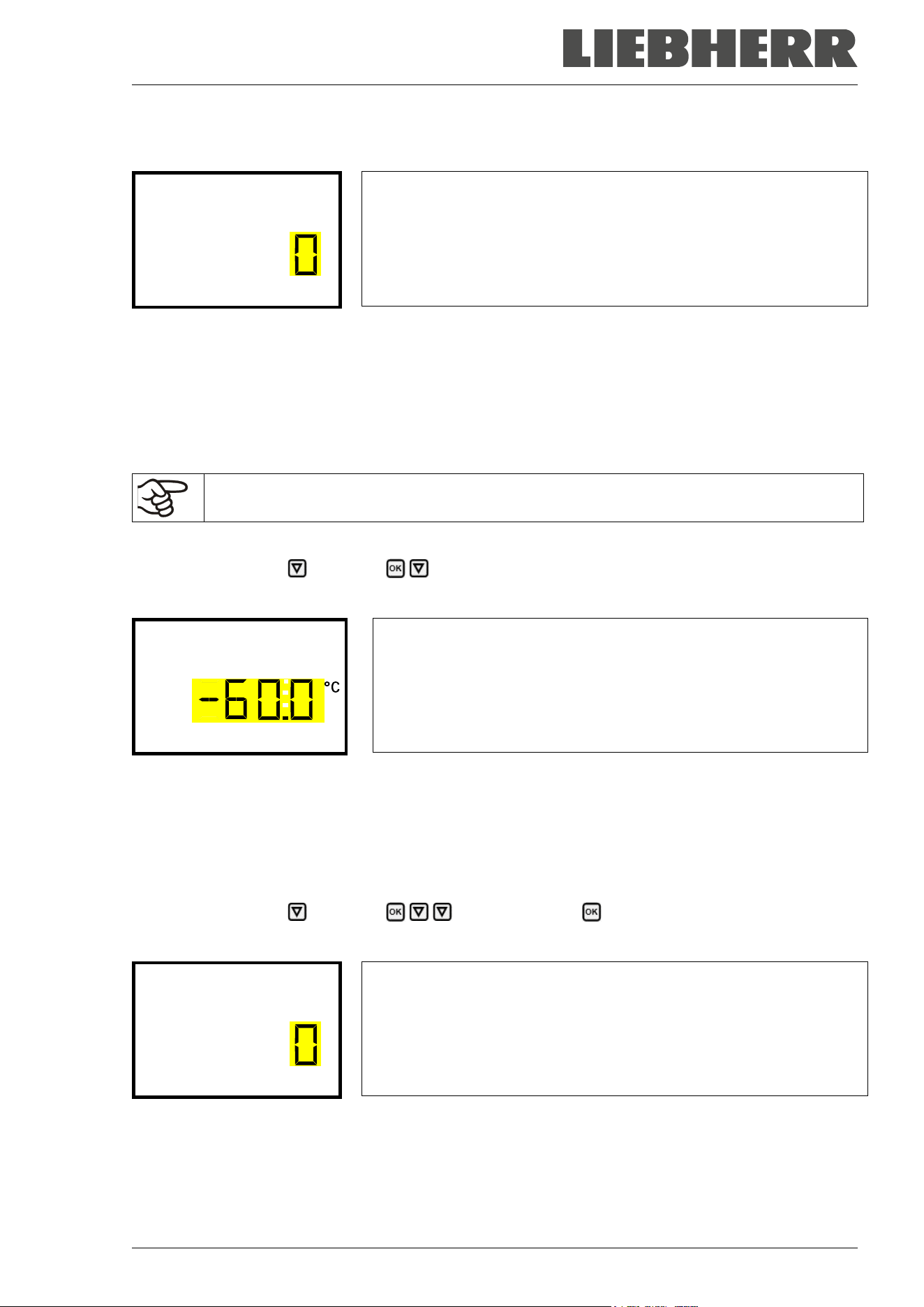
SUFsg 12/2024 Page 82/112
In case there is a CO
2
emergency cooling available, but the setting is “0” (no CO
2
emergency cooling
available), e.g., as a result of retrofitting, press the OK button to enable the setting.
Setting menu “Opt. CO2 emerg. cooling”.
The current setting flashes. Use the arrow buttons to change the set-
ting to “1” (CO
2
emergency cooling available).
Confirm the entry with the OK button.
Opt. CO2 emerg. cooli
Note: For chambers without a CO
2
emergency cooling, the setting must be “0” (no CO
2
emergency cooling
available).
The following controller menus are available only with chambers equipped with the enabled optional CO
2
emergency cooling.
20.3.1 Setting the CO
2
emergency cooling temperature setpoint
It is recommended to set the CO
2
emergency cooling setpoint by at least 10 °C above the
chamber temperature setpoint and above the range alarm limit.
Required access level: “User”.
Path: Normal display Setpoints CO2 emergency cooling
Press the OK button to enable the setting.
Setting the CO
2
emergency cooling temperature setpoint
The current setting flashes. Enter the desired set-point with the arrow
buttons. Setting range: -30 °C up to -70 °C
Confirm the entry with the OK button.
CO2 emergency cooling
With the Back button you can go back to the “Setpoints” submenu and, repeatedly pressing it, to Normal
display.
20.3.2 Activating the CO
2
emergency cooling
Required access level: “User”.
Path: Normal display Setpoints Functions on/off CO2 emer.cooling on/off
Press the OK button to enable the setting.
Setting function 1 “CO2 emer.cooling on/off”.
The current setting flashes. Use the arrow buttons to select between
0 (deactivated emergency cooling) and 1 (activated emergency cool-
ing).
Confirm the setting with the OK button.
CO2 emer.cooling on/o
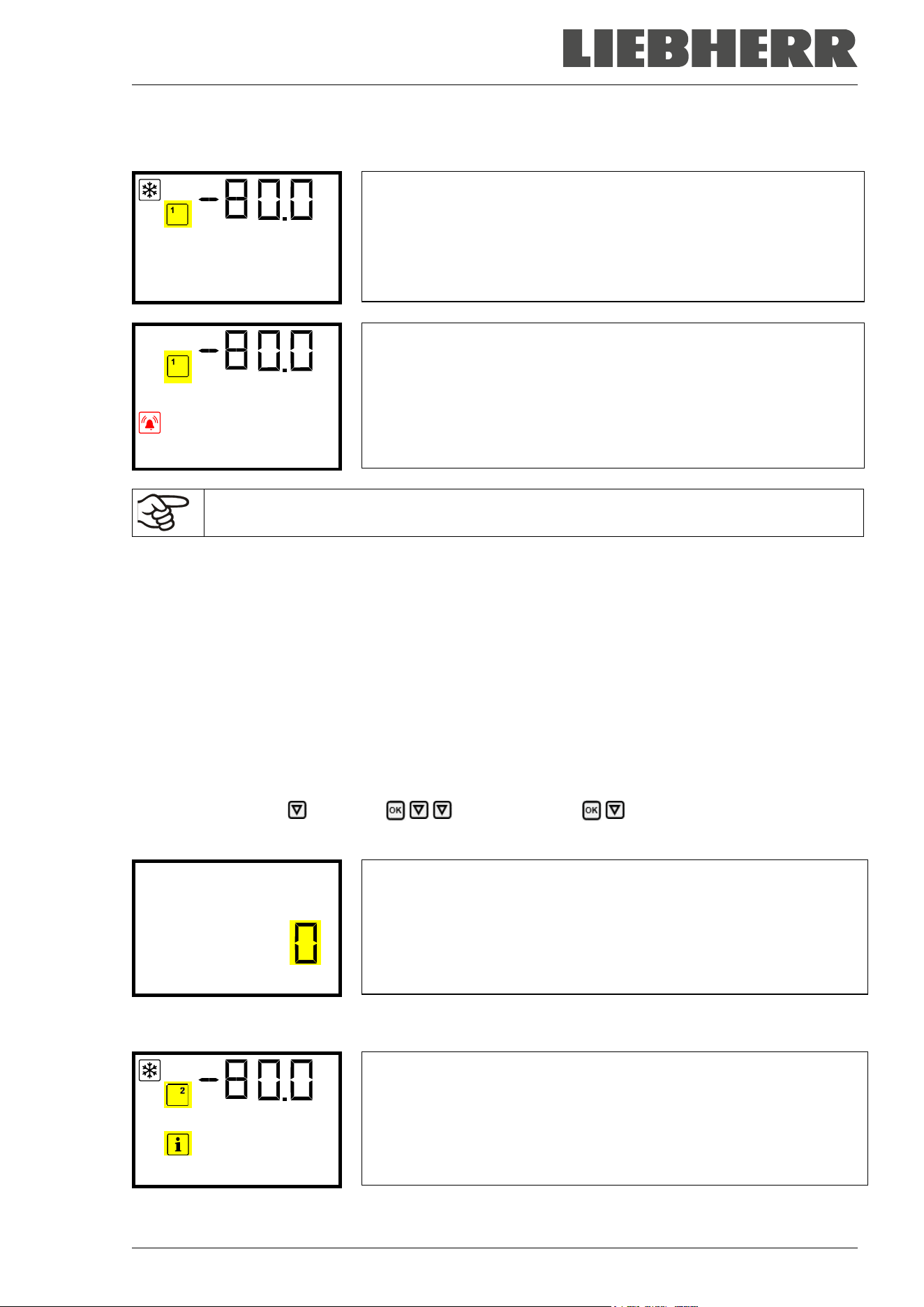
SUFsg 12/2024 Page 83/112
With the Back button you can go back to the “Functions on/off” submenu and, repeatedly pressing it, to
Normal display.
Normal display with activated emergency cooling
Temperature
Normal display with running emergency cooling, showing the alarm
message “CO2 emergency cooling”
CO2 emergency coolin
The valve of the CO
2
gas cylinder must be open, otherwise pressure alarm will occur.
Inactivating the CO
2
emergency cooling
1. Inactivate the CO
2
emergency cooling at the controller.
2. Close the valve of the CO
2
gas cylinder.
20.3.3 Test run of the CO
2
emergency cooling
You can carry out a test run of the CO
2
emergency cooling at any time, even if the CO
2
emergency cooling
is not activated.
The test run of the CO
2
emergency cooling runs after start until it is deactivated again.
Required access level: “User”.
Path: Normal display Setpoints Functions on/off CO2 cooling test on/off
Press the OK button to enable the setting.
Setting function 2 “CO2 cooling test on/off”.
The current setting flashes. Use the arrow buttons to select between
0 (deactivated test run) and 1 (activated test run).
Confirm the setting with the OK button.
CO2 cooling test on/o
With the Back button you can go back to the “Functions on/off” submenu and, repeatedly pressing it, to
Normal display.
Normal display during test run of the CO
2
emergency cooling, showing
the information message “CO2 cooling test active”.
CO2 cooling test acti
After performing a test run, deactivate the setting again.
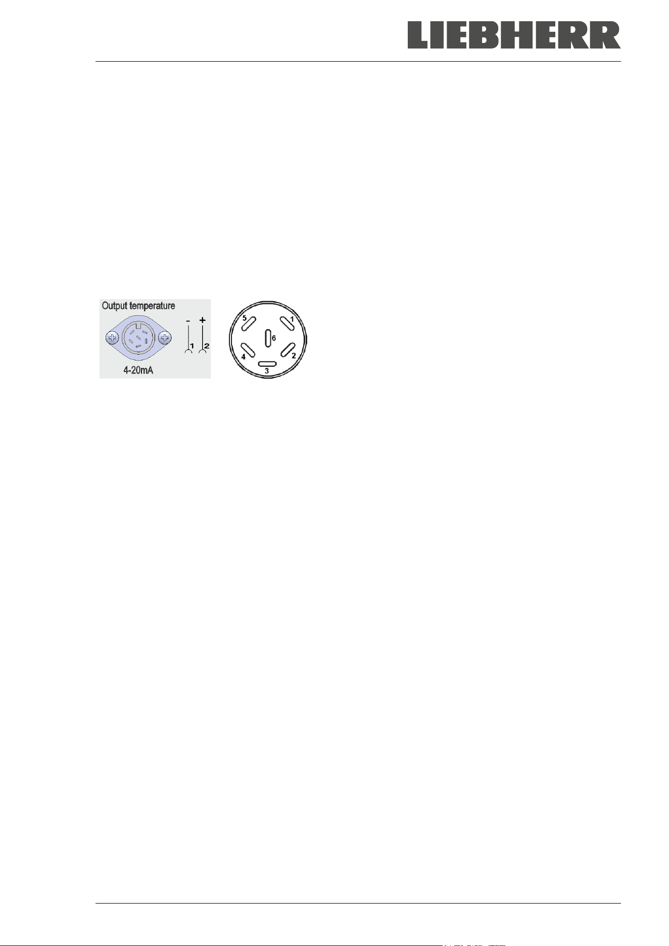
SUFsg 12/2024 Page 84/112
21. Data monitoring and recording
21.1 Ethernet interface
The chamber is regularly equipped with an Ethernet interface (8) for computer communication that can be
used to establish a connection for data exchange and recording. The MAC Address is indicated in the
“Ethernet” controller menu (chap. 15.1.1).
21.2 Analog output for temperature (option)
With this option the freezer is equipped with an analog output 4-20 mA for temperature. This output permits
transmitting data to external data registration systems or devices.
The connection is realized as a DIN socket (10) in the rear connection panel as follows:
ANALOG OUTPUT 4-20 mA DC
PIN 1: Temperature –
PIN 2: Temperature +
Temperature range: +40 °C / 104°F to -100 °C / -148°F
A suitable plug is enclosed.
Figure 20: Pin allocation of socket (10) for option analog output
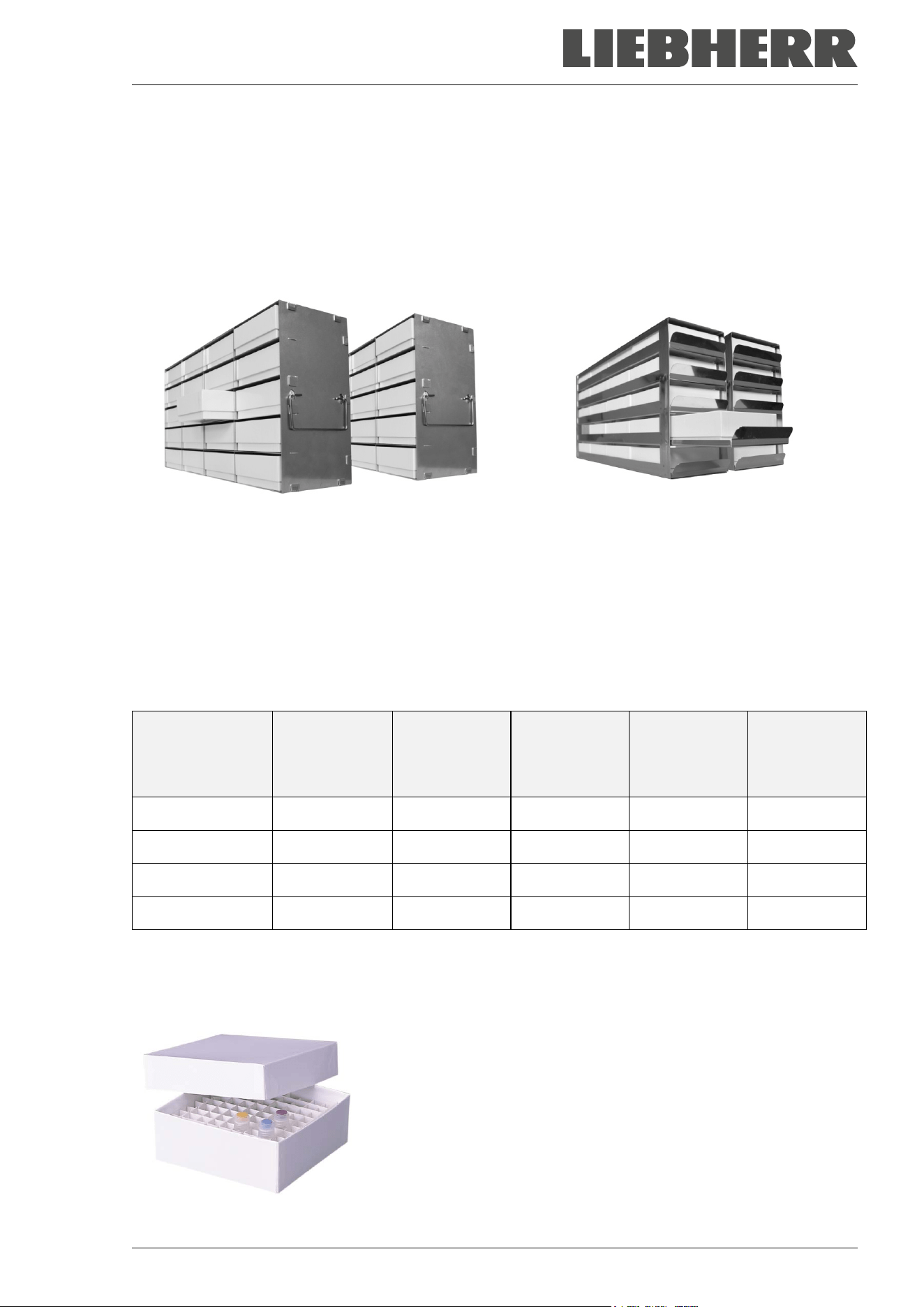
SUFsg 12/2024 Page 85/112
22. Chamber inventory: Storage rack systems and cryo boxes (option)
22.1 Storage rack systems with or without cryo boxes
For optimum use of the available space of the freezer compartments, the following racks are available:
• Side access racks, aluminum or stainless steel
• Sliding drawer racks, stainless steel
Side access racks with cryo boxes Sliding drawer racks with smoothly running
drawers and cryo boxes
Figure 21: Storage rack systems and cryo boxes
All racks are available in two different heights:
• 280 mm / 11 in height for 5 standard cryo boxes (50 mm / 2 in) stacked
• 330 mm / 13 in height for 6 standard cryo boxes (50 mm / 2 in) stacked
Racks are optionally empty or filled with standard cryo boxes
The cardboard cryo boxes come with a divider (9 x 9 grid for 81 samples).
Rack height
No. of sections
for cryo boxes
(height x depth)
Cryo boxes
Side access
rack,
stainless steel
Art. no.
Side access
rack,
aluminum
Art. no.
Sliding
drawer, stain-
less steel
Art. no.
280 mm / 11 in 5 x 4 empty
7790 027 7790 003 7790 031
280 mm / 11 in 5 x 4 with boxes
7790 029 7790 015 7790 033
330 mm / 13 in 6 x 4 empty
7790 028 7790 014 7790 032
330 mm / 13 in 6 x 4 with boxes
7790 030 7790 025 7790 036
22.2 Cryo boxes
Set of 36 standard cryo boxes, cardboard, white, height 50 mm / 2 in with 9 x 9 grid
Figure 22: Cryo boxes with dividers, Art. no. 7790-038
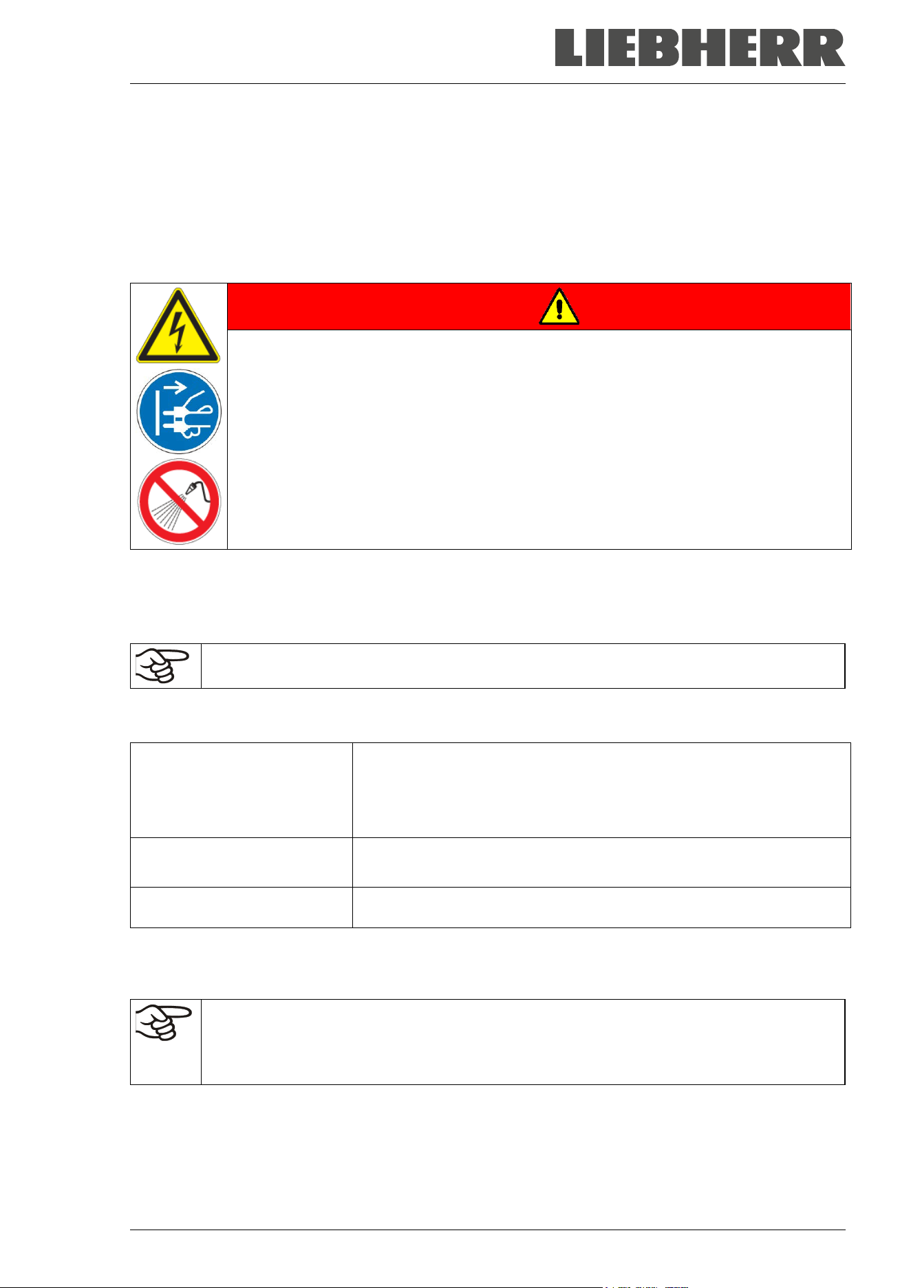
SUFsg 12/2024 Page 86/112
23. Cleaning and decontamination
Clean the chamber after each use to avoid potential corrosion damage by ingredients of the charging ma-
terial.
Prior to renewed startup, allow the chamber to completely dry after all cleaning and decontamination
measures.
During operation: Wipe only the outer surfaces with a humid cloth and then dry it thoroughly
DANGER
Electrical hazard by water entering the chamber.
Deadly electric shock.
∅ Do NOT spill water or cleaning agents over the inner and outer chamber surfaces.
∅ Do NOT put ANY cleaning aids (cloth or brush) into slots or openings on the chamber.
Before cleaning, turn off the chamber at the main power switch and disconnect the
power plug.
Completely dry the chamber before turning it on again.
23.1 Cleaning
Disconnect the chamber from the power supply before cleaning. Disconnect the power plug.
The interior of the chamber must be kept clean. Thoroughly remove any residues of the
charging material.
Wipe the surfaces with a moistened towel. In addition, you can use the following cleaning agents (apply on
a cloth):
Exterior surfaces, door lock
and controller housing with
controller panel, interior (stain-
less steel), shelves, door gas-
kets
Standard commercial cleaning detergents free from acid or halides.
Alcohol based solutions. Neutral cleaning agents.
Connection panel on the
chamber rear
Standard commercial cleaning detergents free from acid or halides.
Neutral cleaning agents.
Zinc coated hinge parts
rear chamber wall
Standard commercial cleaning detergents free from acid or halides.
Do NOT use a neutral cleaning agent on zinc coated surfaces.
Do not use cleaning agents that may cause a hazard due to reaction with components of the chamber or
the charging material. If there is doubt regarding the suitability of cleaning products, please contact the
manufacturer’s service.
Any corrosive damage that may arise following use of other cleaning agents is excluded from
liability by the manufacturer.
Any corrosive damage caused by a lack of cleaning, is excluded from liability by the manufac-
turer.
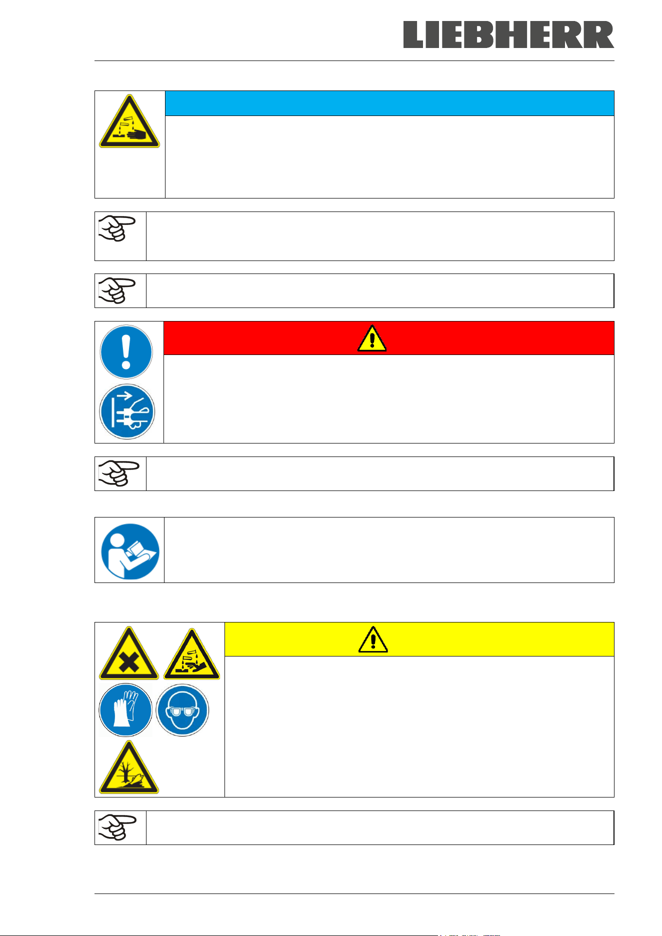
SUFsg 12/2024 Page 87/112
NOTICE
Danger of corrosion by using unsuitable cleaners.
Damage to the chamber.
∅ Do NOT use acidic or chlorine cleaning detergents.
∅ Do NOT use a neutral cleaning agent on the zinc coated hinge parts or the rear cham-
ber wall.
For surface protection, perform cleaning as quickly as possible.
After cleaning completely remove cleaning agents from the surfaces with a moistened towel.
Let the chamber dry.
Soapsuds may contain chlorides and must therefore NOT be used for cleaning.
DANGER
Risk of locking in a person.
Death from suffocation or freezing.
Before closing doors, make sure that nobody is inside.
Pull the power plug before entering the interior (e.g. for cleaning purposes).
With every cleaning method, always use adequate personal safety controls.
Following cleaning, leave the chamber door open or remove the access port plugs.
Neutral cleaning agents may cause health problems in contact with skin and if ingested.
Follow the operating instructions and safety hints labeled on the bottle of the neutral
cleaning agent.
Recommended precautions: To protect the eyes use sealed protective goggles. Wear gloves. Suitable pro-
tective gloves in full contact with media: butyl or nitrile rubber, penetration time >480 minutes.
CAUTION
Danger of chemical burns through contact with skin or ingestion of the
neutral cleaning agent.
Skin and eye damage. Environmental damage.
∅ Do not ingest a neutral cleaning agent. Keep it away from food and
beverages.
∅ Do NOT empty the neutral cleaning agent into drains.
Wear protective gloves and goggles.
Avoid skin contact with the neutral cleaning agent.
The door handle, door hinges and the locking counterpart must be cleaned at least once a
year
SUFsg 12/2024 Page 88/112
23.2 Decontamination / chemical disinfection
The operator must ensure that proper decontamination is performed in case a contamination of the cham-
ber by hazardous substances has occurred.
Disconnect the chamber from the power supply prior to chemical decontamination. Disconnect the power
plug.
Do not use decontamination agents that may cause a hazard due to reaction with components of the cham-
ber or the charging material. If there is doubt regarding the suitability of cleaning products, please contact
the manufacturer’s service.
Any corrosive damage that may arise following use of other disinfectants is excluded from lia-
bility by the manufacturer.
With every decontamination method, always use adequate personal safety controls.
In case of eye contact, the disinfectant spray may cause eye damage due to chemical
burns. Follow the operating instructions and safety hints labeled on the bottle of the disin-
fectant spray.
Recommended precautions: To protect the eyes use sealed protective goggles.
CAUTION
Danger of chemical burns through eye contact with the disinfectant
spray.
Eye damage. Environmental damage.
∅ Do NOT empty the disinfectant spray into drains.
Wear protective goggles.
After using the disinfectant spray, allow the chamber to dry thoroughly, and aerate it suffi-
ciently.
Alternatively, you can use the following disinfectants (apply on a cloth):
Interior (stainless steel)
Standard commercial surface disinfectants free from acid or halides
(not dripping).
Alcohol based solutions.
Compartment doors
Standard commercial surface disinfectants free from acid or halides
(not dripping).
Alcohol based solutions max. 10%
Outer door gasket (PVC) and in-
ner door gasket (silicon)
Alcohol based solutions
Following use, completely remove any disinfectant with a sterile moistened towel from the
surfaces.
Before start-up, the chamber must be absolutely dry and ventilated, as explosive gases may form during
the decontamination process.

SUFsg 12/2024 Page 89/112
24. Maintenance and service, service, troubleshooting, repair, testing
24.1 General information, personnel qualification
• Maintenance
See chap. 24.3.
• Maintenance work by the customer
This work must be carried out regularly by the operating personnel to maintain the chamber function
(chap. 24.2).
For personnel requirements please refer to chap. 1.1.
• Simple troubleshooting
Chap. 24.3 describes troubleshooting by operating personnel. It does not require technical intervention
into the chamber, nor disassembly of chamber parts.
For personnel requirements please refer to chap. 1.1.
• Detailed troubleshooting
If errors cannot be identified with simple troubleshooting, further troubleshooting must be performed by
the manufacturer’s Service or by service partners or technicians qualified by the manufacturer, in ac-
cordance with the description in the Service Manual.
For personnel requirements please refer to the Service Manual.
• Repair
Repair of the chamber can be performed by the manufacturer’s Service or by service partners or tech-
nicians qualified by the manufacturer, in accordance with the description in the Service Manual.
After maintenance, the chamber must be tested prior to resuming operation.
• Electrical testing
To prevent the risk of electrical shock from the electrical equipment of the chamber, an annual repeat
inspection as well as a test prior to initial startup and prior to resuming operation after maintenance or
repair, are required. This test must meet the requirements of the competent public authorities. We rec-
ommend testing under EN 50678/VDE 0701 and EN 50699/VDE 0702 in accordance with the details in
the Service Manual.
For personnel requirements please refer to the Service Manual
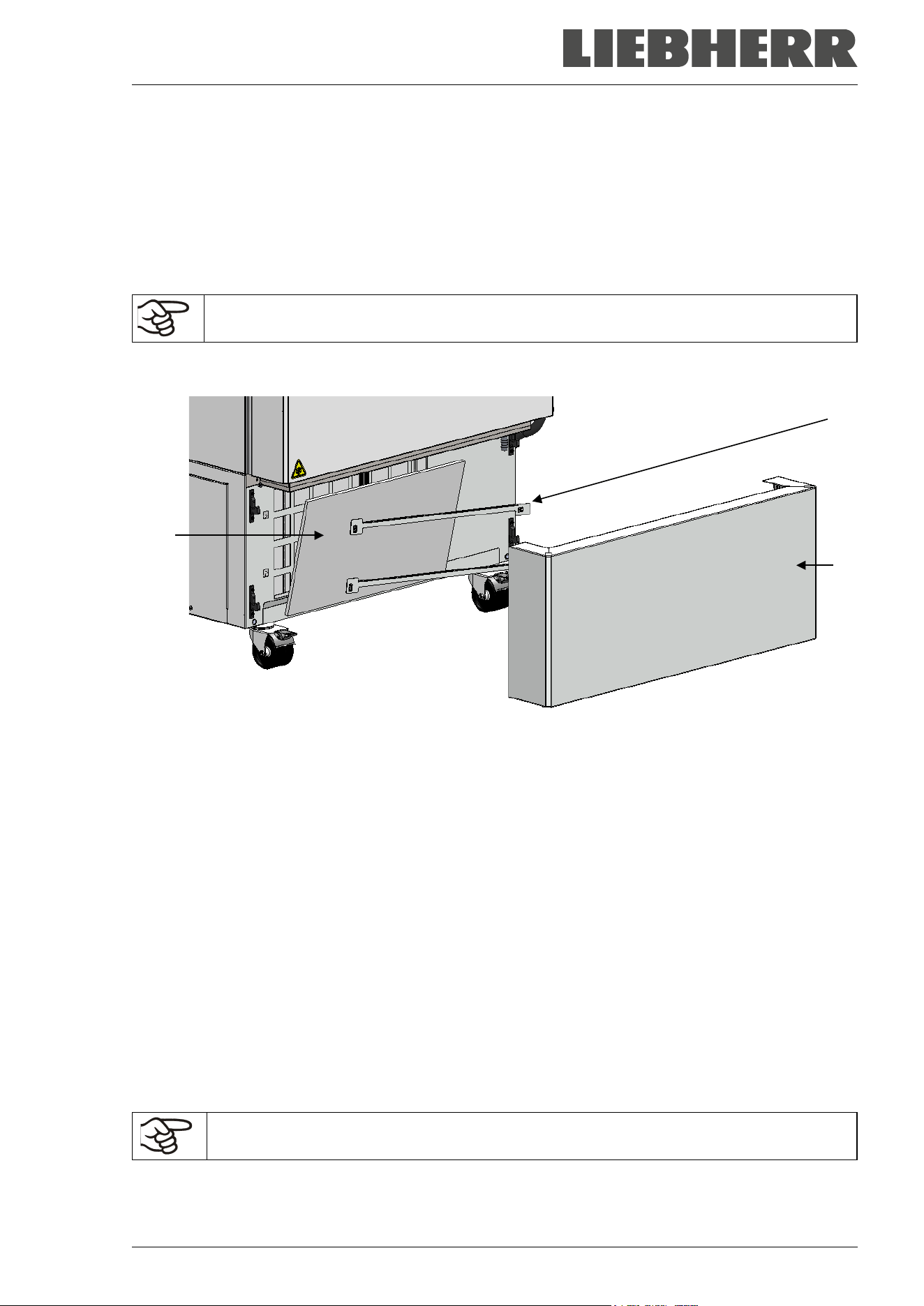
SUFsg 12/2024 Page 90/112
24.2 Maintenance work by the customer
24.2.1 Checking and cleaning / replacing the condenser air filter
The condenser air filter prevents accumulation of dust on the condenser. If the filter is blocked by dust this
may cause decrease or failure of refrigeration.
Check the air filter visually for soiling every month. Especially with the alarm message “Condenser temp.”
(chap. 14.1) the filter may be soiled. You can rinse the filter and use it again.
Regularly check the filter visually for soiling.
The filter is located behind the cover flap (E) in the lower housing cover. You can easily take it out for
cleaning or replacement.
Figure 23: Removing the condenser air filter
(E) cover flap
(E1) condenser air filter
(E2) fixing bars
• Pull the cover flap (E) forward and remove it from the chamber
• Lift the fixing bars (E2) and pull them off to the left
• Remove the condenser air filter (E1)
• Wash the condenser air filter with water and let it dry. If necessary, replace the filter.
• Insert the condenser air filter and then the fixing bars (E2)
• Mount the air filter flap (E).
Fix the condenser air filter, the fixing bars, and the cover flap correctly following cleaning or
replacement of the filter.
(E1)
(E2)
(E)
SUFsg 12/2024 Page 91/112
24.2.2 Cleaning the condenser
Every 6 months remove by suction any visible dust on the condenser lamellas with a vacuum cleaner. If
appropriate, blow through the lamellas with compressed air.
With an increased amount of dust in the ambient air, clean the condenser several times a year. In this case
we recommend to weekly check the condenser lamellas (behind the cover flap (E)). If soiling is visible, turn
off the chamber and remove the dust by suction from the condenser lamellas.
24.2.3 De-icing and defrosting
We recommend for material that could be damage already by slight warming, to provide ade-
quate storage facilities (e.g., in a second chamber / with liquid nitrogen).
Ice may form at the upper part of the chamber and on the inner doors. Excessive frost may lead to increas-
ing the inner chamber temperature. Remove the frost on the doors with an ice scraper.
Regularly (recommendation: every month) remove the frost on the doors with an ice
scraper.
Note: If the door has not been opened for a longer period of time (more than 5 days), it is advisable to de-
ice the door gaskets and the inner opening of the pressure compensation valve (I). After that, the door can
be opened even after a short period of time without applying great force.
After an extended period of operation, defrosting may become necessary:
To defrost the entire chamber, proceed as follows:
• Turn off external protocol systems (option) if applicable.
• Place the stored material in another freezer or in a container refrigerated by dry ice or liquid carbon
dioxide.
• Turn off the chamber at its main power switch (4) and disconnect it from the power supply.
• Open the outer door and all inner doors.
• Allow the frost to melt.
NOTICE
Risk of damage to the interior and to components of the refrigeration system
through scraping and piercing with a sharp instrument.
Damage to the chamber.
∅ NEVER use tools with a sharp edge to remove the frost.
∅ Do NOT use mechanical tools or other aids to accelerate defrosting.
Only use the tools recommended by the manufacturer.
• Wipe up the remains of the defrost water in the interior with absorbent towels
• Let the interior of the freezer dry. Clean and decontaminate it as described in chap. 23
When taking the chamber into operation again, please follow the hints given in chap. 6.2.
• Connect the freezer to the power supply and turn it on with the main power switch (4).
• Operate the chamber for at least 9 hours. Then introduce the material into the freezer.
• Turn on external protocol systems if applicable.
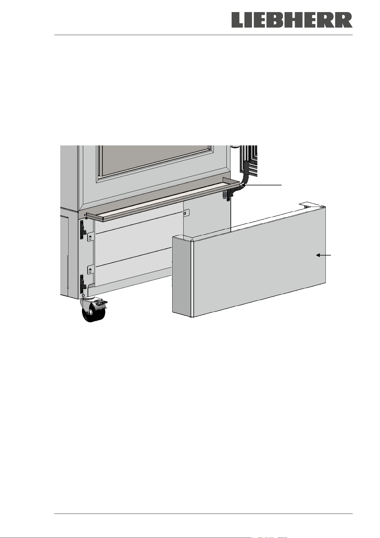
SUFsg 12/2024 Page 92/112
When defrosting, water may accumulate on the shelves and the bottom. Procedure to remove it:
• Carry the water from the freezer shelves and bottom with a wiper into the drain well.
• Then dry all inner chamber equipment with an absorbent towel.
Using the drain well for condensate
The drain well collects the dripping water when defrosting. It is located behind the cover flap (E). During
operation, the hole in the drain well is closed with a plug.
It is required to remove the cover flap (E) for defrosting.
Figure 24: Freezer with drain well in defrosting position
• Turn off the freezer.
• Pull the cover flap (E) forward and remove it from the chamber
• Open the door slightly. Now the melted condensate flows into the drain well.
• Place a reservoir below the hole at the front right corner of the drain well and pull out the plug, so that
the water can drain off.
• After defrosting, close the hole with the plug and insert the cover flap (E).
24.2.4 Maintenance of the door lock
The door handle, door hinges and the locking counterpart must be cleaned at least once a year (chap.
23.1).
(E)
(E)
SUFsg 12/2024 Page 93/112
24.3 Maintenance intervals, service
DANGER
Electrical hazard during live maintenance work.
Deadly electric shock.
∅ The chamber must NOT become wet during operation or maintenance works.
∅ Do NOT remove the rear panel of the chamber and the maintenance flaps on the
chamber sides.
Before conducting maintenance work, turn off the chamber at the main power switch
and disconnect the power plug.
General maintenance work must be conducted by licensed electricians or experts au-
thorized by the manufacturer.
Maintenance work at the refrigeration system must only be conducted by qualified per-
sonnel who underwent training in accordance with EN 13313:2010 (e.g. a refrigeration
technician with certified expert knowledge acc. to regulation 303/2008/EC).
Follow the national statutory regulations.
Ensure regular maintenance work is performed at least once a year and that the legal requirements are
met regarding the qualifications of service personnel, scope of testing and documentation. All work on the
refrigeration system (repairs, inspections) must be documented.
The warranty becomes void if maintenance work is conducted by non-authorized personnel.
With an increased amount of dust in the ambient air, clean the condenser fan (by suction or blowing) several
times a year. Check the condenser air filter frequently and clean / replace it if necessary (chap. 24.2.1).
24.4 Service Reminder
You can display the time until the service due in the controller. Keep the OK button pressed down for 5
seconds.
The remaining time in days until maintenance is due is shown in the
text field of the controller display.
Press the OK button to confirm the message.
Service in 364.9 days
After the recommended maintenance interval (one year of operation) a message appears on the controller.
The message “Service due!” is shown in the text field of the controller
display.
Press the OK button to confirm the message.
Service due!
After one week of operation, the message reappears.
SUFsg 12/2024 Page 94/112
After performing the service, you can reset the service reminder:
Press the OK button for 20 seconds to reset the message for one
year.
The message “Counter has been reset” is shown in the text field of
the controller display.
Press the OK button to confirm the message.
Counter has been rese
24.5 Simple troubleshooting
Defects and shortcomings can compromise the operational safety of the chamber and can lead to risks and
damage to equipment and persons. If there are is a technical fault or shortcoming, take the chamber out of
operation and inform the manufacturer’s Service. If you are not sure whether there is a technical fault,
proceed according to the following list. If you cannot clearly identify an error or there is a technical fault,
please contact the Service.
Only qualified service personnel authorized by the manufacturer must perform repair.
Repaired chambers must comply with the manufacturer’s quality standards.
Fault description
Possible cause
Required measures
General
Chamber without function.
No power supply.
Check connection to power sup-
ply.
Wrong voltage.
Check power supply for correct
voltage (chap.4.5).
Chamber fuse has responded.
Check chamber fuse and replace
it if appropriate. If it responds
again, contact the Service.
Controller defective. Contact the Service.
Alarm message “Door open” Chamber door open. Close chamber door.
Refrigerating performance
No refrigerating performance af-
ter turning on the chamber.
Alarm message “Safety control-
ler”
Limit temperature reached.
Check setting of temperature set-
point and of safety controller. If
appropriate, select suitable limit
value.
Too much external heat load.
Reduce heat load
Controller defective.
Contact the Service.
Safety controller defective.
Semi-conductor relay defective.
SUFsg 12/2024 Page 95/112
Fault description
Possible cause
Required measures
Refrigerating performance (continued)
Chamber refrigerating perma-
nently, set-point not held.
Controller not adjusted, or adjust-
ment interval exceeded.
Calibrate and adjust controller.
Door not shut tightly.
Check if doors are closed.
Frost on door gasket.
Defrost the door gasket with the
ice scraper.
Door opened very frequently.
Open doors less frequently
Introduction of too warm or too
large amount of material.
Cool down material before intro-
ducing and / or load in smaller
portions.
Place of installation too warm.
Select cooler place of installation
or contact the Service.
Door gasket defective.
Contact the Service.
Semiconductor relay defective.
Alarm message “Temp. range”
Current actual temperature value
outside the tolerance range.
Operation temporarily possible.
Check the tolerance range set-
tings. With other error messages
remove the respective cause.
Alarm message “Inner temp.
sensor”
Inner temperature sensor defec-
tive. Control continues using the
safety controller temperature
sensor
Operation temporarily possible.
Contact the Service.
Alarm message “Safety control
sensor”
Safety controller temperature
sensor defective
Operation temporarily possible.
Contact the Service.
Temperature display shows
“- - - - “ or “<-<-< “ or “>->->”
Messages alternating:
“Inner temp. sensor” and “Safety
control sensor”
Inner temperature sensor and
safety controller temperature
sensor defective. Refrigeration is
turned on permanently.
Contact the Service.
Alarm message “Cascade temp.
sensor”.
Failure of Pt100 temperature
sensor. Refrigerating machine in
continuous operation (see chap.
14.4.6).
Contact the Service.
Alarm message “Condensate
temp. sensor” or “Ambient temp.
sensor”
Failure of Pt100 temperature
sensor.
Contact the Service.
No or too low refrigerating per-
formance.
Temperature set-point not set
correctly on the controller.
Set temperature set-point cor-
rectly.
Ambient temperature too high
> 32 °C (chap. 3.4).
Select cooler place of installation.
Too much external heat load.
Reduce heat load.
Pt 100 sensor defective.
Contact the Service.
Refrigerating system defective.
Semiconductor relay defective.
Compressor not switched on.
No or not enough refrigerant.
Alarm message “Continuous op-
eration”
Cooling system error.
Contact the Service.
Semiconductor relay defective.
Controller defective.
Alarm message “Compressor
defective”
Cooling system error.
Turn off the chamber and contact
the Service.
Condenser fan defective.
SUFsg 12/2024 Page 96/112
Fault description
Possible cause
Required measures
Refrigerating performance (continued)
Alarm message “Condenser
temp.”
Condenser air filter soiled.
Clean / replace the condenser air
filter (chap. 24.2.1).
Condenser soiled.
Clean the condenser (chap.
24.2.2).
Ventilation slots are blocked.
Make sure to have free air access
to the chamber at the front and
bottom.
Chamber positioned too close to
the wall (spacers not mounted or
twisted).
Install / check the spacers (chap.
4.2).
Place of installation too hot.
Select cooler place of installation
or contact the Service.
Humidity
Icing at the walls of the inner
chamber
Long time of continuous opera-
tion.
Defrost the chamber (chap. 24.2.3)
Controller
No chamber function
(dark display).
Power failure. Display mode
“Standby” active.
Press any key on the controller
display.
Main power switch (4) is off.
Turn on the main power switch (4).
Menu functions not available.
Menu functions not available with
current authorization level.
Log in with the required higher au-
thorization.
No access to controller
Password incorrect.
Contact the Service.
Acknowledging the alarm does
not cancel the alarm state.
Cause of alarm persists.
Remove cause of alarm. If the
alarm state continues, contact the
Service.
24.6 Sending the chamber back
Chambers may be returned to LIEBHERR (for repair or for other reasons) only after clarification and con-
firmation with the responsible service representative of the respective country.
The contact details are contained in the LIEBHERR service brochure (included with every chamber) or can
be called up online at home.liebher.com/service
.
Before any return, the completed contamination clearance certificate (chap. 28) is required.
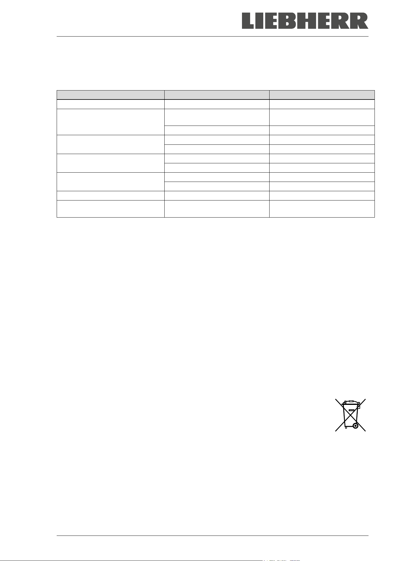
SUFsg 12/2024 Page 97/112
25. Disposal
25.1 Disposal of the transport packing
Packing element
Material
Disposal
Straps to fix packing on pallet
Plastic
Plastic recycling
Wooden transport box (option)
with metal screws
Non-wood (compressed match-
wood, IPPC standard)
Wood recycling
Metal
Metal recycling
Pallet
with foamed plastic stuffing
Solid wood (IPPC standard)
Wood recycling
PE foam
Plastic recycling
Transport box
with metal clamps
Cardboard
Paper recycling
Metal
Metal recycling
Top cover
with foamed plastic stuffing
Cardboard
Paper recycling
PE foam
Plastic recycling
Bag for operating manual
PE foil
Plastic recycling
Insulating air cushion foil (packing
of optional accessories)
PE foil Plastic recycling
If recycling is not possible, all packing parts can also be disposed of with normal waste.
25.2 Decommissioning
• Turn off the chamber with the main power switch (4) and disconnect it from the power supply (pull the
power plug).
• Let the chamber defrost (chap. 24.2.3).
• Temporal decommissioning: See indications for appropriate storage, chap. 3.3.
• Final decommissioning: Dispose of the chamber as described in chap. 25.3 / 25.4.
When restarting the chamber, please pay attention to the corresponding information in chap. 6.2.
25.3 Disposal of the chamber in the member states of the EU
According to Annex I of Directive 2012/19/EU of the European Parliament and of the Council on waste
electrical and electronic equipment (WEEE), the chambers are classified as “monitoring and control instru-
ments” (category 9) only intended for professional use”. They must not be disposed of at public collecting
points.
The chambers and the rechargeable battery bear the symbol for the marking of electrical
and electronic equipment manufactured / placed on the market in the EC after 13 August
2005 and be disposed of in separate collection according to the Directive 2012/19/EU on
waste electrical and electronic equipment (WEEE). WEEE marking: crossed-out wheeled
bin with solid bar under.
Used batteries contain substances that can be harmful to the environment and human
health. These include cadmium (Cd), mercury (Hg) and lead (Pb). These substances are
listed below the crossed-out wheeled bin symbol.
At the end of the chamber’s service life, have it disposed of in accordance with Directive
2012/19 / EU and national regulations or notify the distributor who sold you the chamber,
who will take back and dispose of the chamber according to the Directive 2012/19/EU and
national regulations.
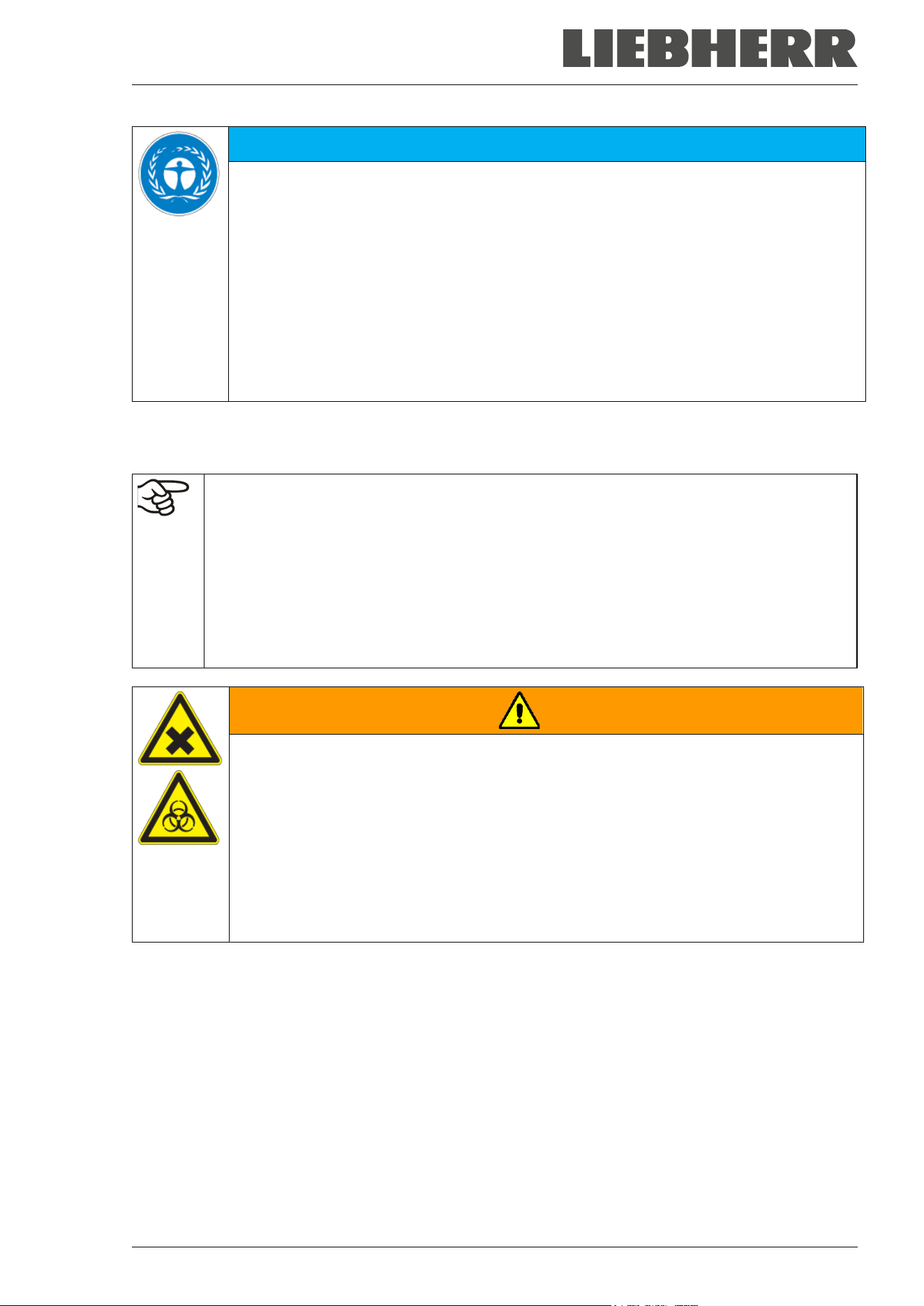
SUFsg 12/2024 Page 98/112
NOTICE
Danger of violation against existing law if not disposed of properly.
Failure to comply with applicable law.
∅ Do NOT dispose of the chambers at public collecting points.
Have the chamber disposed of professionally at a recycling company that is certified ac-
cording to conversion of the Directive 2012/19/EU into national law.
or
Instruct the distributor who sold you the chamber to dispose of it. The agreements apply
that were agreed with the distributor when purchasing the chamber (e.g. his general
terms of payment and delivery).
If your distributor is not able to take back and dispose of the chamber, please contact
the manufacturer’s service.
Certified companies disassemble waste (used) equipment in primary substances for recycling according to
Directive 2012/19/EU. The chambers must be free from toxic, infectious or radioactive substances in order
to eliminate any health hazards to the employees of the recycling companies.
Prior to handing the chamber over to a recycling company, it is the user’s responsibility that it
is free from toxic, infectious or radioactive substances.
• Prior to disposal, clean all introduced or residual toxic substances from the chamber.
• Prior to disposal, disinfect the chamber from all sources of infection. Be aware that sources
of infection may also be located outside the inner chamber.
• If you cannot safely remove all toxic substances and sources of infection from the chamber,
dispose of it as special waste according to national law.
• Fill out the contamination clearance certificate (chap. 28) and enclose it with the chamber.
WARNING
Danger of intoxication and infection through contamination of the chamber with
toxic, infectious or radioactive substances.
Damages to health.
∅ NEVER take a chamber contaminated with toxic substances or sources of infection for
recycling according to Directive 2012/19/EU.
Prior to disposal, remove all toxic substances and sources of infection from the cham-
ber.
A chamber from which all toxic substances or sources of infection cannot be safely re-
moved must be considered as “special” waste according to national law. Dispose of it
accordingly.
The disposal of batteries within the EU must be carried out in accordance with the current EU directives as
well as national, regional and local environmental protection regulations.
The refrigerants used R290 (propane, GWP 3) and R170 (ethane, GWP 6) are inflammable at ambient
pressure. A suction is not required. Ensure the compliance with the applicable legal requirements regarding
qualification of staff, and documentation.
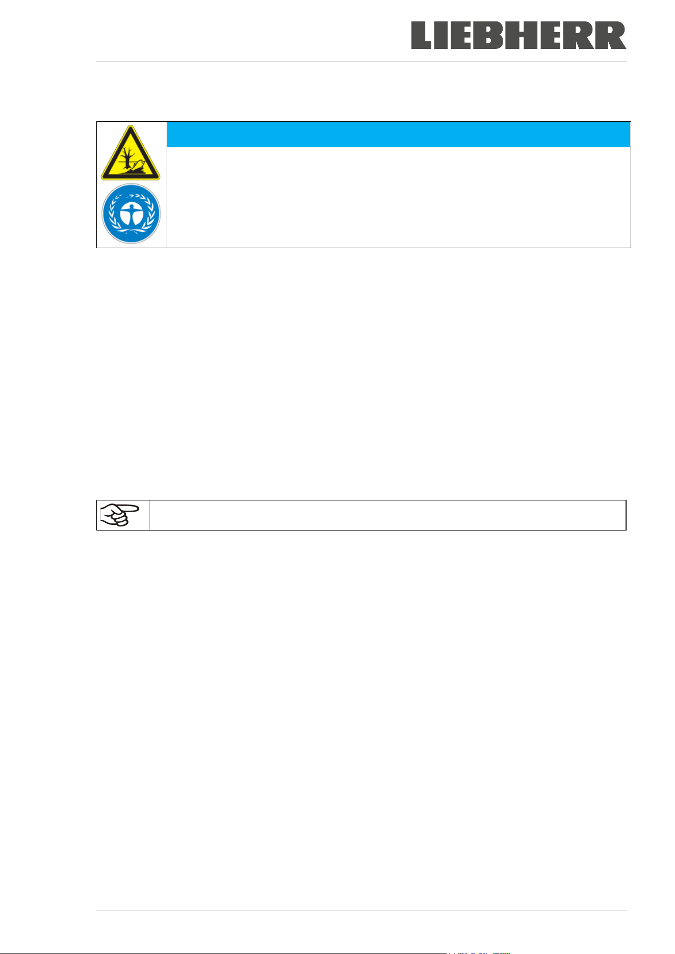
SUFsg 12/2024 Page 99/112
25.4 Disposal of the chamber in non-member states of the EU
NOTICE
Danger of violation against existing law if not disposed of properly.
Failure to comply with applicable law. Alteration of the environment.
For final decommissioning and disposal of the chamber, please contact the manufac-
turer’s Service.
Follow the statutory regulations for appropriate, environmentally friendly disposal.
The chamber is equipped with a rechargeable battery (12 V, 7.2 Ah) which can be recycled. Used batteries
must be disposed of properly. Please ensure that you dispose of the battery in accordance with the regu-
lations in force in your country.
The refrigerants used R290 (propane, GWP 3) and R170 (ethane, GWP 6) are inflammable at ambient
pressure. A suction is not required. Ensure the compliance with the applicable legal requirements regarding
qualification of staff, and documentation.
26. Technical description
26.1 Factory calibration and adjustment
The chambers were calibrated and adjusted in factory. Calibration and adjustment were performed using
standardized test instructions, according to the QM DIN EN ISO 9001 system applied by the manufacturer.
All test equipment used is subject to the administration of measurement and test equipment that is also a
constituent part of the manufacturer’s QM DIN EN ISO 9001 system. They are controlled and calibrated
according to regulations at regular intervals.
Repeated calibrations are recommended in periods of 12 months.
26.2 Over current protection
The chambers are equipped with an internal fuse not accessible from outside. If this fuse is blown, please
inform an electronic engineer or the manufacturer’s service.
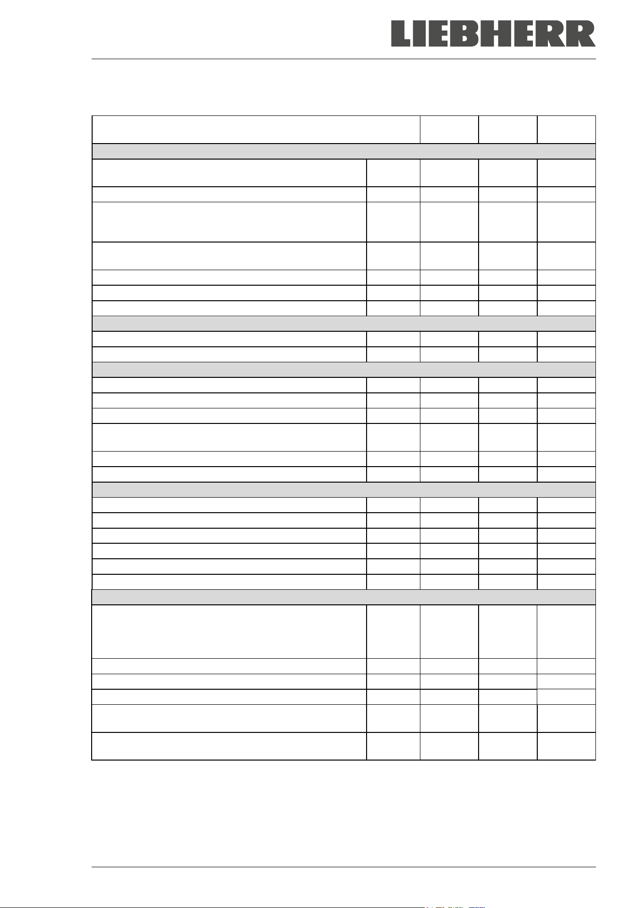
SUFsg 12/2024 Page 100/112
26.3 Technical data
Chamber size
SUFsg
3501
SUFsg
5001
SUFsg
7001
Exterior dimensions
Width, gross (including hinges, door lock and controller
housing)
mm / inch
802 / 31.58
920 / 36.2 1204 / 47.4
Height, gross (incl. castors)
mm / inch
1966 / 77.4
1966 / 77.4
1966 / 77.4
Depth, gross (including power connection, without door
lock and controller housing (equals depth when door
open))
mm / inch
850 / 33.5 850 / 33.5 850 / 33.5
Depth, gross (including power connection, door lock and
controller housing)
mm / inch
1005 / 39.6
1005 / 39.6
1005 / 39.6
Wall clearance rear (minimum)
mm / inch
100 / 3.9
100 / 3.9
100 / 3.9
Wall clearance side (side without hinges) (minimum)
mm / inch
100 / 3.9
100 / 3.9
100 / 3.9
Wall clearance side (side with hinges) (minimum)
mm / inch
250 / 9.84
245 / 9.6
245 / 9.6
Doors
Number of chamber doors
1
1
1
Number of compartment doors
2
2
2
Interior dimensions
Quantity of compartments
2
2
2
Width of inner chamber
mm / inch
486 / 19.13
606 / 23.9
890 / 35.0
Height of interior
mm / inch
1300 / 51.2
1300 / 51.2
1300 / 51.2
Height of individual compartment (with shelves) mm / inch
312-319
12.3-12.6
312-319
12.3-12.6
312-319
12.3-12.6
Depth of inner chamber
mm / inch
636 / 25.04
636 / 25.04
636 / 25.04
Interior volume, total
l
402 / 14.2
501 / 17.7
736 / 26.0
Shelves
Quantity of shelves (regular / max.)
3 / 11
3 / 11
3 / 11
Width of shelf
mm / inch
458 / 18.03
580 / 22.8
860 / 33.9
Depth of shelf
mm / inch
590 / 23.2
590 / 23.2
590 / 23.2
Permitted max. load per shelf (regular shelf)
kg / lbs
40 / 88
50 / 110
50 / 110
Permitted max. load of inner chamber bottom
kg / lbs
40 / 88
50 / 110
50 / 110
Permitted total load
kg / lbs
160 / 353
200 / 441
200 / 441
Temperature data
Setting and control range
°C
°F
-40 up to -
90
-40 up to -
130
-40 up to -
90
-40 up to -
130
-40 up to -
90
-40 up to -
130
Temperature uniformity (variation) at -80 °C / -112 °F
± K
3.5
2.5
2.5
Temperature fluctuation at -80 °C / -112 °F
± K
4.0
1.5
1.5
Pull-down time from +25 °C / 71.6 °F to -80 °C / -112 °F
minutes
180
360
450
Pull-up time in case of power failure from -80 °C /
-112
°F to -60 °C / -76 °F
minutes 170 230 250
Pull-up time in case of power failure from -80 °C /
-112
°F to 0 °C / -32 °F
minutes 1170 2160 2220
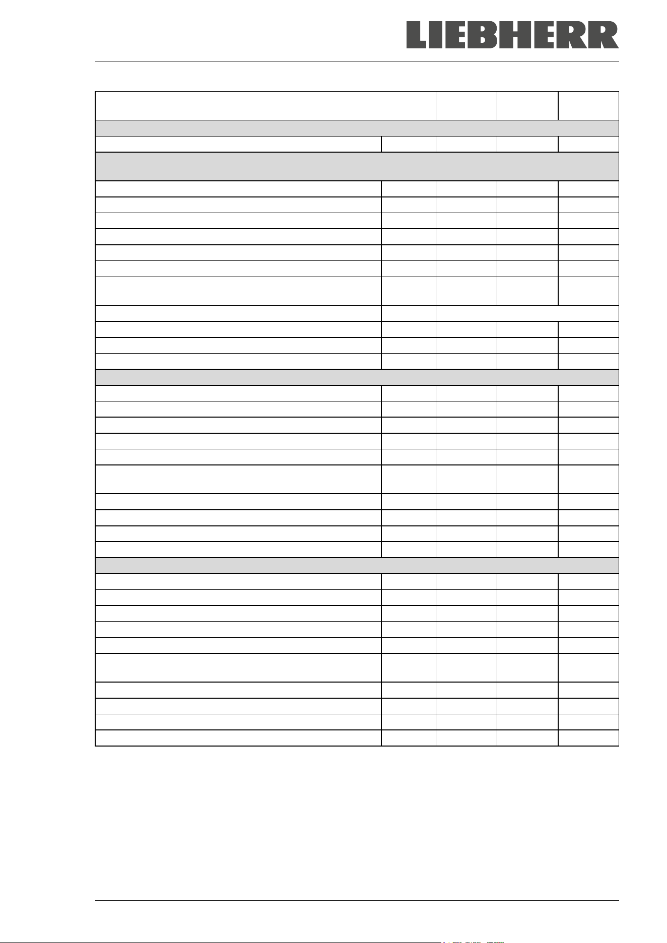
SUFsg 12/2024 Page 101/112
Chamber size
SUFsg
3501
SUFsg
5001
SUFsg
7001
Weight
Weight of the chamber (empty)
kg / lbs
230 / 507
259 / 571
301 / 664
Electrical Data SUFsg 3501,001 / SUFsg 5001,001 / SUFsg 7001,001/ SUFsg 5001,H72 / SUFsg
7001,H72 (230 V)
IP system of protection acc. to EN 60529
IP
20
20
20
Nominal voltage (±10%) at 50 Hz power frequency
V
230
230
230
Current type
1N~
1N~
1N~
Nominal power
kW
1.6
1.6
1.6
Nominal current
A
7.0
7.0
7.0
Nominal current, chamber with water cooling
A
--
8.8
8.8
IEC connector plug and cable
mm / inch
3000 /
118.1
3000 /
118.1
3000 /
118.1
Power plug
Grounded plug
Installation category acc. to IEC 61010-1
II
II
II
Pollution degree acc. to IEC 61010-1
2
2
2
Internal over-current release category C, 2 poles
A
10
10
10
Electrical Data SUFsg 3501,137 / SUFsg 5001,137 / SUFsg 7001,137 (115 V)
IP system of protection acc. to EN 60529
IP
20
20
20
Nominal voltage (+/- 10%) at 60 Hz power frequency
V
115
115
115
Current type
1N~
1N~
1N~
Nominal power
kW
1.4
1.4
1.4
Nominal current
A
11.7
11.7
11.7
IEC connector plug and cable
mm / inch
3000 /
118.1
3000 /
118.1
3000 /
118.1
Power plug
NEMA
5-15P
5-15 P
5-15 P
Installation category acc. to IEC 61010-1
II
II
II
Pollution degree acc. to IEC 61010-1
2
2
2
Internal over-current release category C, 2 poles
A
15
15
15
Electrical Data SUFsg 5001,123 / SUFsg 7001,123 (208-230 V)
IP system of protection acc. to EN 60529
IP
--
20
20
Nominal voltage (+/- 10%) at 60 Hz power frequency
V
--
208 - 230
208 - 230
Current type
--
2~
2~
Nominal power
kW
--
1.8
1.8
Nominal current
A
--
8.2
8.2
IEC connector plug and cable
mm / inch
--
3000 /
118.1
3000 /
118.1
Power plug
NEMA
--
6-15P
6-15P
Installation category acc. to IEC 61010-1
--
II
II
Pollution degree acc. to IEC 61010-1
--
2
2
Internal over-current release category C, 2 poles
A
--
10
10
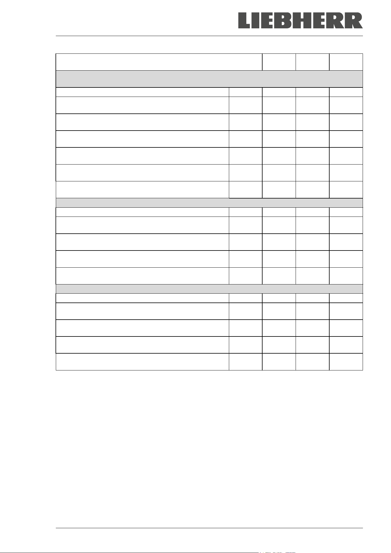
SUFsg 12/2024 Page 102/112
Chamber size
SUFsg
3501
SUFsg
5001
SUFsg
7001
Environment-specific data SUFsg 3501,001 / SUFsg 5001,001 / SUFsg 7001,001/ SUFsg 5001,H72 /
SUFsg 7001,H72 (230 V)
Noise level (mean value)
dB (A)
47
47
47
Energy consumption at set point -80 °C/ -
112 °F
, with an
ambient temperature of +20 °C / 68°F
kWh/day 7.5 7,9 8,1
Average heat dissipation at set-point -80 °C / -112 °F, with
an ambient temperature of +20 °C / 68 °F
W 310 330 340
Filling weight of refrigerant R290 (propane)
(1
st
stage cooling, GWP 3)
kg 0.15 0.15 0.15
Filling weight of refrigerant R170 (ethane)
(2
nd
stage cooling, GWP 6)
kg 0.145 0.15 0.15
Chamber with water cooling: Filling weight of refrigerant
R290 (propane) (1
st
stage cooling, GWP 3)
kg --- 0.15 0.15
Chamber with water cooling: Filling weight of refrigerant
R170 (ethane) (2
nd
stage cooling, GWP 6)
kg --- 0.15 0.15
Environment-specific data SUFsg 3501,137 / SUFsg 5001,137 / SUFsg 7001,137 (115 V)
Noise level (mean value)
dB (A)
47
47
47
Energy consumption at set point -80 °C/ -112 °F, with an
ambient temperature of +20 °C / 68°F
kWh/day 7.5 7.9 8.1
Average heat dissipation at set-point -80 °C / -112 °F, with
an ambient temperature of +20 °C / 68 °F
W 310 330 340
Filling weight of refrigerant R290 (propane)
(1
st
stage cooling, GWP 3)
kg 0.15 0.15 0.15
Filling weight of refrigerant R170 (ethane)
(2
nd
stage cooling, GWP 6)
kg 0.145 0.15 0.15
Environment-specific data SUFsg 5001,123 / SUFsg 7001,123 (208-230 V)
Noise level (mean value)
dB (A)
--
47
47
Energy consumption at set-point -80 °C/ -112 °F, with an
ambient temperature of +20 °C / 68°F
kWh/day -- 7.9 8.1
Average heat release at set-point -80 °C/ -112 °F, with an
ambient temperature of +20 °C / 68 °F
W -- 330 330
Filling weight of refrigerant R290 (propane)
(1
st
stage cooling, GWP 3)
kg -- 0.15 0.15
Filling weight of refrigerant R170 (ethane)
(2
nd
stage cooling, GWP 6)
kg -- 0.15 0.15
All technical data is specified for chambers with unloaded standard equipment at an ambient temperature
of +22 °C +/- 3°C / 71.6 °F +/- 5.4 °F and a power supply voltage fluctuation of +/-10. Specification of the
sound pressure level +/- 1 dB(A). Technical data is determined in accordance to standardized internal
guidelines and DIN 12880:2007.
All indications are average values, typical for chambers produced in series. We reserve the right to
change technical specifications at any time.
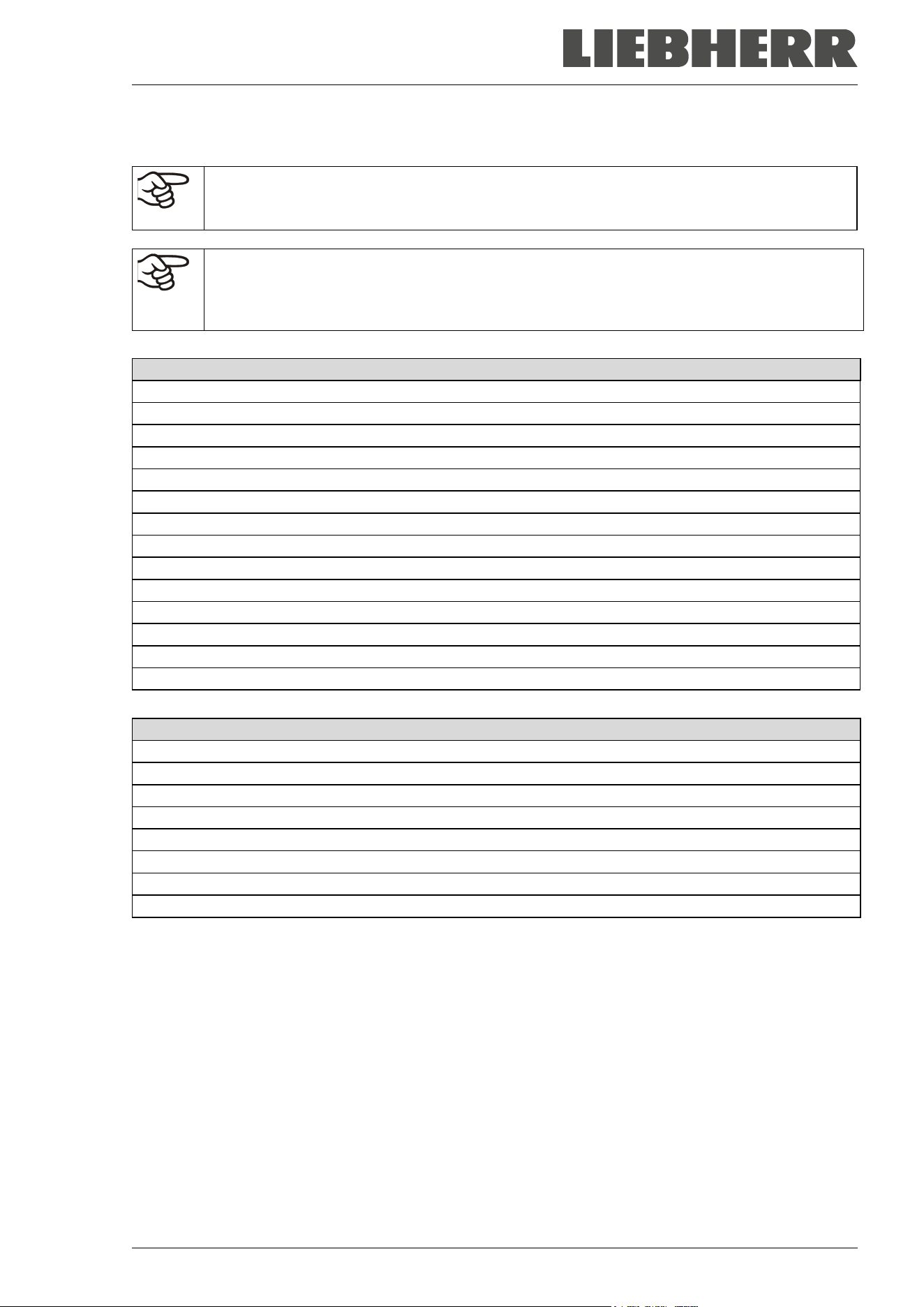
SUFsg 12/2024 Page 103/112
26.4 Equipment and options, accessories and spare parts (extract)
To operate the chamber, use only original accessories from the manufacturer or accessories
/ components from third-party suppliers authorized by the manufacturer. The user is responsi-
ble for any risk arising from using unauthorized accessories.
The manufacturer is responsible for the safety features of the chamber only provided skilled
electricians or qualified personnel authorized by the manufacturer perform all maintenance
and repair, and if components relating to chamber safety are replaced in the event of failure
with original spare parts.
Regular equipment
Microprocessor chamber controller for temperature
Electronic error auto-diagnosis system with zero-voltage relay alarm output
Ethernet interface for computer communication
USB interface
Safety controller
VIP technology (Vacuum Insulation Panels)
Powerful, energy-efficient refrigeration system
Four compartments, two compartment doors
Three shelves
Three 28 mm access ports
Connection kit for cooling water (chambers with water cooling)
Battery-buffered alarm system
Voltage 230 V, 50 Hz
Voltage 115 V, 60 Hz or 208-230 V, 60 Hz
Options / accessories
Stainless steel shelf set, 1 shelf with shelf holders
Side access rack, stainless steel or aluminum, empty or with cryo boxes
Sliding drawer rack, stainless steel or aluminum, empty or with cryo boxes
Cryo boxes with dividers, set of 39 pc.
Lockable protective flap for the main power switch
Connection kit for cooling water (chambers with water cooling)
CO
2
emergency cooling
Analog output 4-20 mAmp for temperature with 6 pole socket, plug included
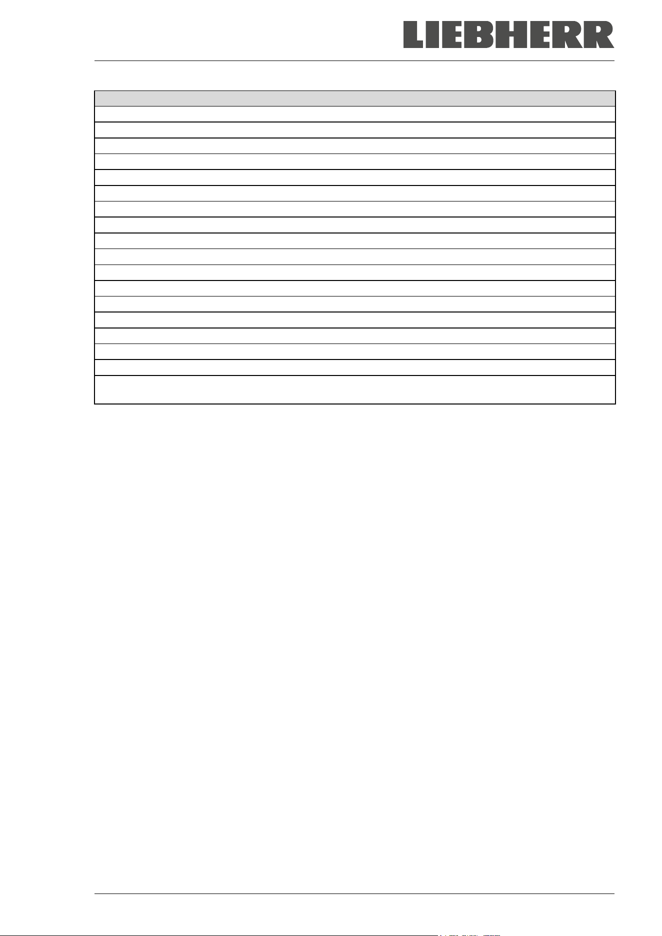
SUFsg 12/2024 Page 104/112
Spare parts
Outer chamber door gasket, silicon
Inner chamber door gasket, silicon
Compartment door, regular
Compartment door with gasket, foamed (option)
Standard shelf for compartment
Rechargeable battery 12V, 7.2 Ah
Replacement condenser air filter
Fuse 4A / 250V - F - 6,3x32mm
Over-current release category C 10 A (for 230 V and 208-230 V chambers)
IEC connector plug for EU with 3 m cable
IEC connector plug for Switzerland with 3 m cable
IEC connector plug for UK with 3 m cable
Spacers
Insulated compartment doors SUFsg 5001
Insulated compartment doors SUFsg 7001
Front castor with lock
Rear castor
CO
2
emergency cooling, retrofit kit, installation by Service of the authorized dealer. Adjustable between -
40 °C / -40 °F and -70 °C / -94 °F
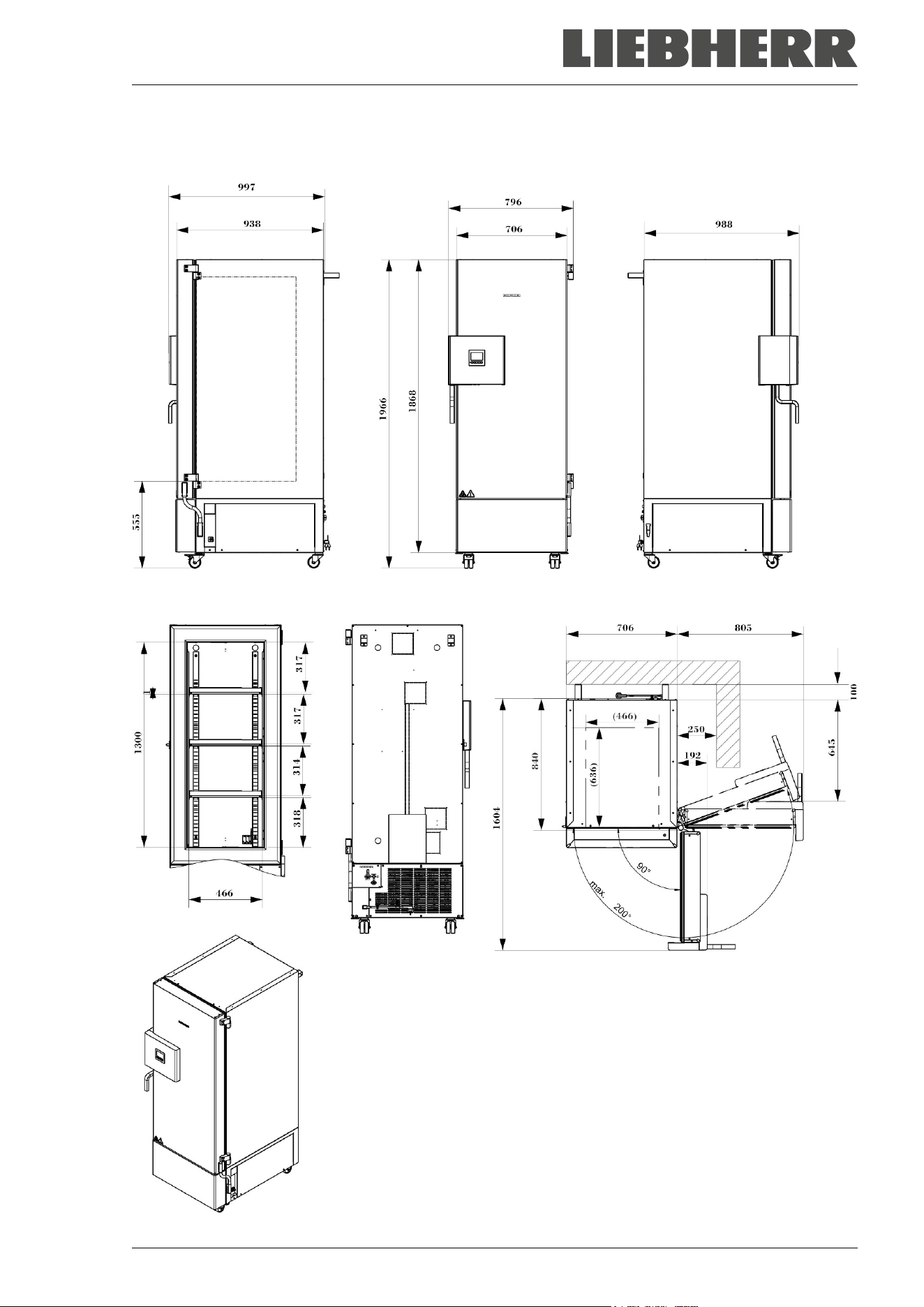
SUFsg 12/2024 Page 105/112
26.5 Dimensions SUFsg 3501
Dimensions in mm
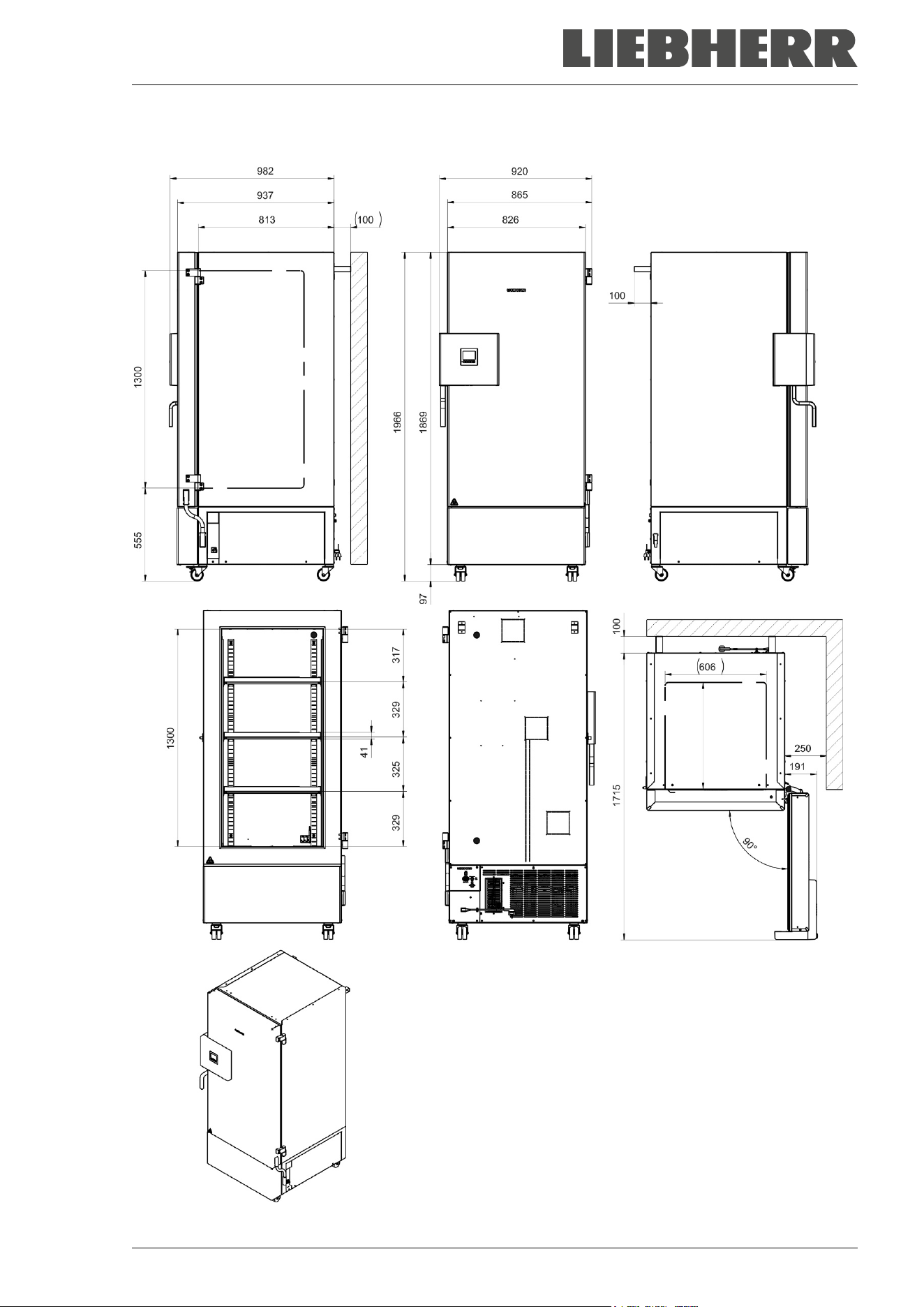
SUFsg 12/2024 Page 106/112
26.6 Dimensions SUFsg 5001
Dimensions in mm
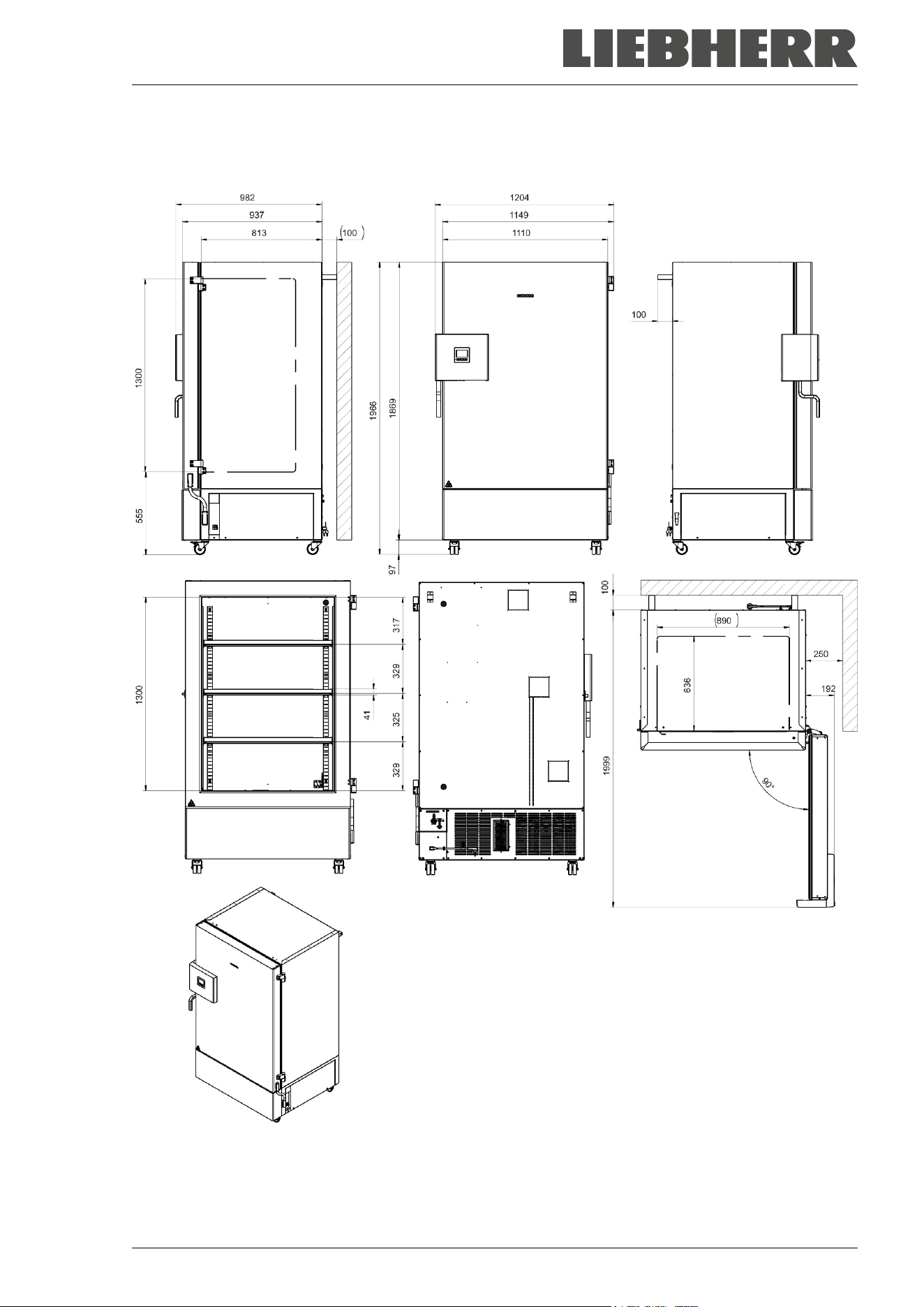
SUFsg 12/2024 Page 107/112
26.7 Dimensions SUFsg 7001
Dimensions in mm

SUFsg 12/2024 Page 108/112
27. EU Declaration of Conformity
The refrigerant circuit has been checked for leaks.
The chamber complies with the relevant safety regulations as well as the EU Directives 2014/35/EU,
2014/30/EU, and 2011/65/EU.
The full text of the EU Declaration of Conformity is available at the following internet address:
www.liebherr.com
SUFsg 12/2024 Page 109/112
28. Contamination clearance certificate
Declaration regarding safety and health
Erklärung zur Sicherheit and gesundheitlichen Unbedenklichkeit
The German Ordinance on Hazardous Substances (GefStofV), and the regulations regarding safety at the
workplace, require that this form be filled out for all products that are returned to us, so that the safety and
the health of our employees can be guaranteed.
Die Sicherheit und Gesundheit unserer Mitarbeiter, die Gefahrstoffverordnung GefStofV und die Vorschriften zur Si-
cherheit am Arbeitsplatz machen es erforderlich, dass dieses Formblatt für alle Produkte, die an uns zurückgeschickt
werden, ausgefüllt wird.
Note: A repair is not possible without a completely filled out form.
Ohne Vorliegen des vollständig ausgefüllten Formblattes ist eine Reparatur nicht möglich.
• A completely filled out form must be transmitted must be communicated to the responsible LIEBHERR
service agency in advance in advance, so that this information is available before the
equipment/component part arrives. A second copy of this form must accompany the
equipment/component part. In addition, the carrier should be notified.
Eine vollständig ausgefüllte Kopie dieses Formblattes soll per Fax unter Nr. +49 (0) 7462 2005 93555 oder Brief
vorab an uns gesandt werden, so dass die Information vorliegt, bevor das Gerät/Bauteil eintrifft. Eine weitere Kopie
soll dem Gerät/Bauteil beigefügt sein. Ggf. ist die Spedition zu informieren.
• Incomplete information or non-conformity with this procedure will inevitably lead to substantial delays in
processing. Please understand the reason for this measure, which lies outside our area of influence,
and help us to speed up this procedure.
Unvollständige Angaben oder Nichteinhalten dieses Ablaufs führen zwangsläufig zu beträchtlichen Verzögerungen
in der Abwicklung. Bitte haben Sie Verständnis für Maßnahmen, die außerhalb unserer Einflussmöglichkeiten liegen
und helfen Sie mit, den Ablauf zu beschleunigen.
• You can find information on data protection at https://www.liebherr.com/privacydocs/LWL/LWL-DSE-
Geschaeftspartner.pdf
Hinweise zum Datenschutz finden Sie unter dem angegebenen Link.
• Please fill out this form completely.
Bitte unbedingt vollständig ausfüllen!
1. Unit/ component part / type /
Gerät / Bauteil / Typ:
2. Serial No. /
Serien-Nr.:
3. Details about utilized substances / biological substances /
Einzelheiten über die eingesetzten
Substanzen/biologische Materialien:
3.1 Designations /
Bezeichnungen:
a) ____________________________________________________________________________
b) ____________________________________________________________________________
c) ____________________________________________________________________________
3.2 Safety measures required for handling these substances /
Vorsichtsmaßnahmen beim Umgang
mit diesen Stoffen:
a) ____________________________________________________________________________
b) ____________________________________________________________________________
c) ____________________________________________________________________________
SUFsg 12/2024 Page 110/112
3.3 Measures to be taken in case of skin contact or release into the atmosphere /
Maßnahmen
bei Personenkontakt oder Freisetzung:
a) ____________________________________________________________________________
b) ____________________________________________________________________________
c) ____________________________________________________________________________
d) ____________________________________________________________________________
3.4 Other important information that must be taken into account /
Weitere zu beachtende und
wichtige Informationen:
a) ____________________________________________________________________________
b) ____________________________________________________________________________
c) ____________________________________________________________________________
4. Declaration on the risk of these substances (please checkmark the applicable items) /
Erklärung zur Gefährlichkeit der Stoffe (bitte Zutreffendes ankreuzen) :
4.1 For non toxic, non radioactive, biologically harmless materials /
für nicht giftige, nicht
radioaktive, biologisch ungefährliche Stoffe:
We hereby guarantee that the above-mentioned unit / component part… / Wir versichern, dass o.g.
Gerät/Bauteil...
Has not been exposed to or contains any toxic or otherwise hazardous substances /
weder giftige
noch sonstige gefährliche Stoffe enthält
oder solche anhaften.
That eventually generated reaction products are non-toxic and also do not represent a hazard /
auch
evtl. entstandene Reaktionsprodukte weder giftig sind noch sonst eine Gefährdung darstellen.
Eventual residues of hazardous substances have been removed / evtl. Rückstände von Gefahrstoffen
entfernt wurden.
4.2 For toxic, radioactive, biologically harmful or hazardous substances, or any other hazard
ous materials / für giftige, radioaktive, biologisch bedenkliche bzw. gefährliche Stoffe oder anderweitig
gefährliche Stoffe.
We hereby guarantee that … / Wir versichern, dass …
The hazardous substances, which have come into contact with the above-mentioned equipment /
component part, have been completely listed under item 3.1 and that all information in this regard is
complete /
die gefährlichen Stoffe, die mit dem o.g. Gerät/Bauteil in Kontakt kamen, in 3.1 aufgelistet sind und
alle Angaben vollständig sind.
That the unit /component part has not been in contact with radioactivity / das Gerät/Bauteil nicht mit
Radioaktivität in Berührung kam
5. Kind of transport / transporter /
Transportweg/Spediteur:
Transport by (means and name of transport company, etc.) /
Versendung durch (Name Spediteur o.ä.)
___________________________________________________________________________________
Date of dispatch to the manufacturer /
Tag der Absendung an den Hersteller:
___________________________________________________________________________________
SUFsg 12/2024 Page 111/112
We hereby declare that the following measures have been taken / Wir erklären, dass folgende Maßnah-
men getroffen wurden:
Hazardous substances were removed from the unit including component parts, so that no hazard exists
for any person in the handling or repair of these items /
das Gerät/Bauteil wurde von Gefahrstoffen befreit,
so dass bei Handhabung/Reparaturen für die betreffenden Person keinerlei Gefährdung besteht
The unit was securely packaged and properly identified /
das Gerät wurde sicher verpackt und vollständig
gekennzeichnet.
Information about the hazardousness of the shipment (if required) has been provided to the transporter
/
der Spediteur wurde (falls vorgeschrieben) über die Gefährlichkeit der Sendung informiert.
We hereby commit ourselves and guarantee that we will indemnify the manufacturer for all damages that
are a consequence of incomplete or incorrect information provided by us, and that we will exempt the
manufacturer from eventual damage claims by third parties. /
Wir versichern, dass wir gegenüber dem Hersteller
für jeden Schaden, der durch unvollständige und unrichtige Angaben entsteht, haften und den Hersteller gegen even-
tuell entstehende Schadenansprüche Dritter freistellen.
We are aware that, in accordance with Article 823 of the German Civil Code (BGB), we are directly liable
with regard to third parties, in this instance especially the employees of the manufacturer, who have been
entrusted with the handling / repair of the unit / component. /
Es ist uns bekannt, dass wir gegenüber Dritten –
hier insbesondere mit der Handhabung/Reparatur des Geräts/des Bauteils betraute Mitarbeiter der Firma des Her-
stellers - gemäß §823 BGB direkt haften.
Name: _______________________________________________________________________
Title /
Position: _______________________________________________________________________
Date /
Datum: _______________________________________________________________________
Signature /
Unterschrift: _______________________________________________________________
Company stamp /
Firmenstempel:
Equipment that is returned to the factory for repair must be accompanied by a completely
filled out contamination clearance certificate. For service and maintenance on site, such a
contamination clearance certificate must be submitted to the service technician before the
start of any work. No repair or maintenance of the equipment is possible, without a properly
filled out contamination clearance certificate.