Instruction Manual
Issued: 11-12-2025
Revised: 4-14-2026
hoshizakiamerica.com
Modular Crescent Cuber
Models
KM-322_522_622MAK
KM-330_530_730MAK
KM-930MAK2
KM-1130MAK2
2
WARNING
Only qualied service technicians should install and service the appliance.
To obtain the name and phone number of your local Hoshizaki Certied Service
Representative, visit www.hoshizakiamerica.com. No installation, operation,
maintenance, or service should be undertaken until the technician has thoroughly
read this Instruction Manual. No service should be undertaken until the technician
has thoroughly read the service manual available at www.hoshizakiamerica.com.
Likewise, the owner/manager should not proceed to operate the appliance until the
installer has instructed them on its proper operation. Failure to install, operate, and
maintain the appliance in accordance with this manual will adversely affect safety,
performance, component life, and warranty coverage and may result in costly water
damage. Proper installation is the responsibility of the installer. Product failure or
property damage due to improper installation is not covered under warranty.
Hoshizaki provides this manual primarily to assist qualied service technicians in the
installation, operation, maintenance, and service of the appliance.
Should the reader have any questions or concerns which have not been satisfactorily
addressed, please call, send an e-mail message, or write to the Hoshizaki Technical
Support Department for assistance.
Phone: 1-800-233-1940; (770) 487-2331
E-mail: tech-suppor[email protected]
618 Highway 74 South
Peachtree City, GA 30269
Attn: Hoshizaki Technical Support Department
NOTE: To expedite assistance, all correspondence/communication MUST include the
following information:
• Model Number
• Serial Number
• Complete and detailed explanation of the problem.

3
CONTENTS
Important Safety Information ................................................................................................. 4
I. Specications ...................................................................................................................... 9
A. Electrical and Refrigerant Data ..................................................................................... 9
B. Dimensions/Connections .............................................................................................11
II. Installation Instructions .................................................................................................... 14
A. Location ...................................................................................................................... 15
B. Checks Before Installation ........................................................................................... 16
C. How to Remove Panels ............................................................................................... 17
D. Dispenser Unit/Ice Storage Bin and Icemaker Setup .................................................. 18
E. Electrical Connection .................................................................................................. 19
F. Water Supply and Drain Connections .......................................................................... 20
G. Final Checklist ............................................................................................................ 22
1. Pre-Startup ............................................................................................................. 22
2. Post-Startup ........................................................................................................... 22
III. Operating Instructions ..................................................................................................... 23
A. Important Notes About Usage ..................................................................................... 23
B. Startup ........................................................................................................................ 24
1. Bin Control Setting ................................................................................................. 24
2. Appliance Startup and Bin Control Check ............................................................. 30
C. Alarm Safeties ............................................................................................................. 34
IV. Maintenance ................................................................................................................... 35
A. User Maintenance Schedule ....................................................................................... 35
B. Service Maintenance Schedule ................................................................................... 36
C. Cleaning and Sanitizing Instructions ........................................................................... 37
V. Preparing the Appliance for Periods of Non-Use ............................................................. 40
VI. Decommissioning and Disposal ..................................................................................... 43
IMPORTANT
This manual should be read carefully before the appliance is installed and operated.
Read the warnings and guidelines contained in this manual carefully as they
provide essential information for the continued safe use and maintenance of the
appliance. Retain this manual for any further reference that may be necessary.
4
Important Safety Information
Throughout this manual, notices appear to bring your attention to situations which could
result in death, serious injury, damage to the appliance, or damage to property.
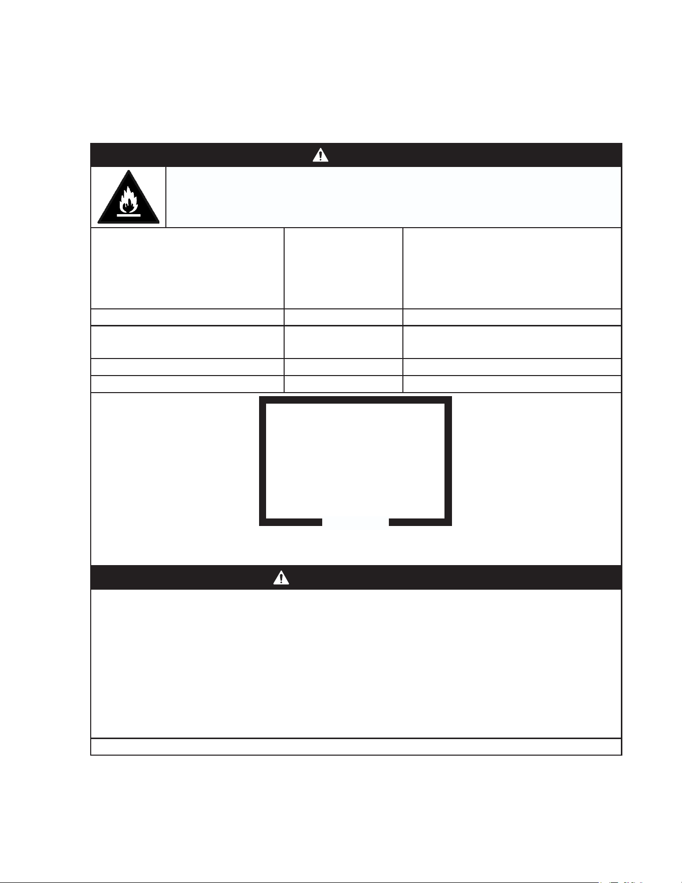
R-290 Class A3 Flammable Refrigerant Used*
DANGER
Indicates a hazardous situation that, if not avoided, will result in
death or serious injury.
WARNING
Indicates a hazardous situation that, if not avoided, could result in
death or serious injury.
NOTICE
Indicates a situation that, if not avoided, could result in damage to
the appliance or property.
IMPORTANT
Indicates important information about the use and care of the
appliance.
DANGER
Risk of Fire or Explosion
Flammable Refrigerant Used*
• Only qualied service technicians should
install and service the appliance.
• No installation, operation, or maintenance
should be undertaken until the technician
has thoroughly read this Instruction
Manual. All safety precautions must be
followed.
• No service should be undertaken until
the technician has thoroughly read the
Service Manual available at
www.hoshizakiamerica.com. All safety
precautions must be followed.
• This appliance to be installed in
accordance with the Safety Standard for
Refrigeration Systems ANSI/ASHRAE 15.
• Follow handling instructions carefully in
compliance with national regulations.
• Do not use mechanical devices or other
means to accelerate the defrosting
process or to clean, other than those
recommended by the manufacturer.
• Do not puncture refrigerant tubing. Risk
of re or explosion due to puncture
of refrigerant tubing; follow handling
instructions carefully.*
• Servicing shall be done by trained service
personnel with certied competence
in handling ammable refrigerants to
minimize the risk of possible ignition due
to incorrect parts or improper service.*
• Component parts shall be replaced with
like components, so as to minimize the
risk of possible ignition due to incorrect
parts.*
• Dispose of properly in accordance with
federal or local regulations.
• Do not pierce or burn.
• Be aware that refrigerants may not contain
an odor.
• Do not damage the refrigeration circuit.
• See nameplate for R-290 refrigerant
charge:*
• If greater than 114 g (4 oz.), do not install
in public corridor or lobby.
• If greater than 152 g (5.3 oz.), do not
install within 6 m (20 ft) of open ame.
• The appliance shall be stored in a room
without continuously operating ignition
sources (for example: open ames, an
operating gas appliance, or an operating
electric heater).*
*This statement applies to models utilizing R-290 refrigerant.
5
• Do not place any potential ignition sources
in or near the appliance.
• Keep clear of obstruction all ventilation
openings in the appliance enclosure or in
the structure for building-in.
• No potential sources of ignition are to be
used in the searching for or detection of
refrigerant leaks.
• Do not use electrical appliances inside
the appliance unless they are of the type
recommended by the manufacturer.
• Do not store explosive substances such as
aerosol cans with a ammable propellant
in this appliance.
• Check that cabling will not be subject
to wear, corrosion, excessive pressure,
vibration, sharp edges, or any other
adverse environmental effects. The check
shall also take into account the effects of
aging or continual vibration from sources
such as compressors or fans.
• Ensure that the area is in the open or that
it is adequately ventilated before breaking
into the system or conducting any hot
work. A degree of ventilation shall continue
during the period that the work is carried
out. The ventilation should safely disperse
any released refrigerant and preferably
expel it externally into the atmosphere.
• This appliance shall be used on a
dispenser unit/ice storage bin without
electrical components or one designed
to be used with ammable refrigerants,
and of size or type as indicated in this
manual.*
*This statement applies to models utilizing
R-290 refrigerant.
DANGER continued
Risque D'Incendie ou D'Explosion
Fluide Frigorigène Inammable Utilisé
• Seuls des techniciens de service qualiés
doivent installer et entretenir l'appareil.
• Aucune installation, opération ou
maintenance ne doit être entreprise avant
que le technicien n'ait lu attentivement
ce manuel d'instructions. Toutes les
précautions de sécurité doivent être
suivies.
• Aucune opération d'entretien ne doit être
entreprise avant que le technicien n'ait
lu attentivement le manuel d'entretien
disponible sur le site
www.hoshizakiamerica.com. Toutes les
précautions de sécurité doivent être
suivies.
• Cet appareil doit être installé
conformément à la norme de sécurité
pour les systèmes de réfrigération
ANSI/ASHRAE 15.
• Suivez attentivement les instructions
de manutention conformément aux
réglements nationaux.
• Ne pas utiliser de dispositifs mécaniques
ou d'autres moyens pour accélérer le
processus de dégivrage ou pour nettoyer,
autres que ceux recommandés par le
fabricant.
• Ne pas perforer la conduite de uide
frigorigène. Risque d'incendie ou
d'explosion en cas de perforation d'une
canalisation de uide frigorigène;
suivez attentivement les instructions de
manutention.*
• L’entretien doit être effectué par du
personnel formé et certié pour la
manipulation de réfrigérants inammables
an de réduire au minimum le risque
d'inammation dû à des pièces
incorrectes ou à un entretien inadéquat.*
*Cette déclaration s’applique aux modèles
utilisant le réfrigérant R-290.
6
DANGER Continué
• Les pièces doivent être remplacées
par des pièces similaires, de manière
à réduire au minimum le risque
d'inammation dû à des pièces
incorrectes.*
• Mettre au rebut conformément aux
réglements fédéraux ou locaux.
• Ne pas percer ou brûler.
• Attention, les uides frigorigénes peuvent
ne pas dégager d'odeur.
• Ne pas endommager les composants du
circuit de réfrigération.
• Voir plaque signalétique pour la charge de
réfrigérant R-290:*
• Si elle est supérieure à 114 g (4 oz.), ne
pas l'installer dans un couloir public ou
un hall d'entrée.
• Si elle est supérieure à 152 g (5.3 oz.),
ne pas l'installer à moins de 6 m (20 pi)
d'une amme nue.
• L'appareil doit être entreposé dans
un local ne contenant pas de sources
d'inammation permanentes (ammes
nues, appareil à gaz ou dispositif de
chauffage électrique en fonctionnement,
par exemple).*
• Ne placer aucune source d'inammation
potentielle à l'intérieur ou à proximité de
l'appareil.
• Ne pas obstruer les ouvertures de
ventilation dans l'enceinte de l'appareil ou
dans la structure d'encastrement.
• Aucune source potentielle d'inammation
ne doit être utilisée pour rechercher ou
détecter des fuites de réfrigérant.
• Ne pas utiliser d'appareils électriques à
l'intérieur de l'appareil, sauf s'ils sont du
type recommandé par le fabricant.
• Ne pas entreposer dans cet appareil
des substances explosives telles que
des bombes aérosols contenant un gaz
propulseur inammable.
• Vérier que le câblage ne sera pas soumis
à l'usure, à la corrosion, à une pression
excessive, à des vibrations, à des arêtes
vives ou à tout autre effet environnemental
négatif. Le contrôle doit également prendre
en compte les effets du vieillissement ou
des vibrations continues provenant de
sources telles que les compresseurs ou
les ventilateurs.
• S'assurer que la zone est à l'air libre ou
qu'elle est correctement ventilée avant de
pénétrer dans le système ou d'effectuer un
travail à chaud. Une certaine ventilation
doit être maintenue pendant la durée des
travaux. La ventilation doit permettre de
disperser en toute sécurité tout réfrigérant
libéré et, de préférence, de l'expulser dans
l'atmosphère.
• Cet appareil doit être utilisé sur un
distributeur/bac de stockage à glace
sans composants électriques ou conçu
pour être utilisé avec des réfrigérants
inammables, et d’une taille ou d’un type
conforme aux indications de ce manuel.*
*Cette déclaration s’applique aux modèles
utilisant le réfrigérant R-290.
7
WARNING
The appliance should be destined only to
the use for which it has been expressly
conceived. Any other use should be
considered improper and therefore
dangerous. The manufacturer cannot be
held responsible for injury or damage
resulting from improper, incorrect, and
unreasonable use. Failure to install,
operate, and maintain the appliance
in accordance with this manual will
adversely affect safety, performance,
component life, and warranty coverage
and may result in costly water damage.
To reduce the risk of death, electric
shock, serious injury, or re, follow
basic precautions including the
following:
• This appliance is intended for use at
altitudes up to 7,000 m (22,965 ft).
• Wear appropriate personal protective
equipment (PPE) when servicing the
appliance.
• The appliance must be installed in
accordance with applicable national, state,
and local codes and regulations.
• Electrical connection must be hard-wired
and must meet national, state, and local
electrical code requirements. Failure to
meet these code requirements could result
in death, electric shock, serious injury, re,
or damage.
• The appliance requires an independent
power supply of proper capacity. See the
nameplate for electrical specications.
Failure to use an independent power
supply of proper capacity can result in a
tripped breaker, blown fuse, damage to
existing wiring, or component failure.
This could lead to heat generation or re.
• THE APPLIANCE MUST BE
GROUNDED. Failure to properly ground
the icemaker could result in death or
serious injury.
• To reduce the risk of electric shock, do not
touch the control switch or mode switch
with damp hands.
• Move the control switch to the "OFF"
position and turn off the power supply
before servicing. Lockout/Tagout to
prevent the power supply from being
turned back on inadvertently.
• Risk of electric shock. Power switch in
"OFF" position does not de-energize all
loads Use extreme caution and exercise
safe electrical practices.
• Do not make any alterations to the
appliance. Alterations could result in
electric shock, injury, re, or damage to
the appliance.
• Appliance is heavy. Use care when lifting
or positioning. Work in pairs when needed
to prevent injury or damage.
• The appliance is not intended for use by
persons (including children) with reduced
physical, sensory, or mental capabilities,
or lack of experience and knowledge,
unless they have been given supervision
or instruction concerning use of the
appliance by a person responsible for their
safety.
• Do not splash, pour, or spray water
directly onto or into the appliance. This
might cause short circuit, electric shock,
corrosion, or failure.
• Children should be supervised to ensure
that they do not play with the appliance.
• Do not climb, stand, or hang on the
appliance or allow children or animals to
do so. Serious injury could occur or the
appliance could be damaged.
• Do not use combustible spray or place
volatile or ammable substances in or
near the appliance. They might catch re.
• Keep the area around the appliance clean.
Dirt, dust, or insects in the appliance could
cause harm to individuals or damage to
the appliance.

8
NOTICE
• Follow the water supply, drain connection,
and maintenance instructions carefully to
reduce the risk of costly water damage.
• In areas where water damage is a
concern, install in a contained area with a
oor drain.
• Install the appliance in a location that stays
above freezing. Normal operating ambient
temperature must be within 45°F to 100°F
(7°C to 38°C).
• Level the ice dispenser/ice storage
bin prior to installing the icemaker.
After icemaker installation, conrm the
icemaker is level. An out-of-level icemaker
could result in improper operation, poor
performance, water leaks, and/or damage
to the icemaker.
• Do not leave the appliance on during
extended periods of non-use, extended
absences, or in sub-freezing temperatures.
To properly prepare the appliance for
these occasions, follow the instructions in
"V. Preparing the Appliance for Periods of
Non-Use."
• If water collects in the bin and will not
drain, turn off the appliance and close the
water supply line shut-off valve. Call for
service.
• Do not place objects on top of the
appliance.
• The dispenser unit/ice storage bin is for ice
use only. Do not store anything else in the
dispenser unit/ice storage bin.
• Protect the oor when moving the
appliance to prevent damage to the oor.
9
I. Specications
A. Electrical and Refrigerant Data
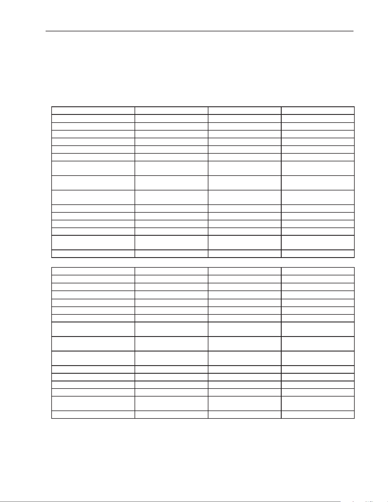
The rating label and nameplate provide electrical and refrigerant data and Year of
Manufacture (YOM). The rating label can be seen by removing the front panel. The
nameplate is located on the rear panel. For certication marks, see the nameplate.
We reserve the right to make changes in specications and design without prior notice.
Model Number KM-322MAK KM-522MAK KM-622MAK
AC SUPPLY VOLTAGE ~115/60/1 ~115/60/1 ~115/60/1
COMPRESSOR 115V 7.1RLA 50LRA 115V 8.7RLA 49.5LRA 115V 11.8RLA 72LRA
PUMP 120V 0.5FLA 10W 120V 0.5FLA 10W 120V 0.5FLA 10W
FAN 125V 1.0FLA 1/15 HP 125V 1.0FLA 1/15 HP 125V 1.0FLA 1/15 HP
OTHER 115V 0.10A 115V 0.10A 115V 0.10A
MAXIMUM FUSE SIZE 15 AMPS 20 AMPS 20 AMPS
MAX. HACR BREAKER
(USA ONLY)
15 AMPS 20 AMPS 20 AMPS
MAX. CIRCUIT BREAKER
(CANADA ONLY)
15 AMPS 20 AMPS 20 AMPS
MINIMUM CIRCUIT
AMPACITY
15 AMPS 20 AMPS 20 AMPS
DESIGN PRESSURE kPa (PSI) HI-2730 (396) LO-897 (130) HI-2730 (396) LO-897 (130) HI-2730 (396) LO-897 (130)
REFRIGERANT G (OZ.) R-290 145 (5.1) R-290 150 (5.3) R-290 150 (5.3)
CLIMATIC CLASS 5 5 5
INSULATION BLOWING GAS HFO 1233zd(E) HFO 1233zd(E) HFO 1233zd(E)
MINIMUM ROOM FLOOR
AREA M² (FT² )
6.9 (74.7) 7.2 (77.3) 7.2 (77.3)
HARVEST RATE ≤1,000 LB/DAY (BATCH) ≤1,000 LB/DAY (BATCH) ≤1,000 LB/DAY (BATCH)
Model Number KM-330MAK KM-530MAK KM-730MAK
AC SUPPLY VOLTAGE ~115/60/1 ~115/60/1 ~115/60/1
COMPRESSOR 115V 6.9RLA 45.0LRA 115V 9.1RLA 49.5LRA 115V 10.5RLA 72.0LRA
PUMP 115V 0.46FLA 49W 115V 0.46FLA 49W 115V 0.46FLA 49W
FAN 115V 1.0FLA 1/15 HP 115V 1.0FLA 1/15 HP 115V 0.9FLA 1/15 HP
OTHER 115V 0.15A 115V 0.15A 115V 0.15A
MAXIMUM FUSE SIZE 15 AMPS 20 AMPS 20 AMPS
MAX. HACR BREAKER
(USA ONLY)
15 AMPS 20 AMPS 20 AMPS
MAX. CIRCUIT BREAKER
(CANADA ONLY)
15 AMPS 20 AMPS 20 AMPS
MINIMUM CIRCUIT
AMPACITY
15 AMPS 20 AMPS 20 AMPS
DESIGN PRESSURE kPa (PSI) HI-2730 (396) LO-945 (137) HI-2730 (396) LO-945 (137) HI-2730 (396) LO-945 (137)
REFRIGERANT G (OZ.) R-290 150 (5.3) R-290 150 (5.3) R-290 300 (10.6)
CLIMATIC CLASS 5 5 5
INSULATION BLOWING GAS HFO 1233zd(E) HFO 1233zd(E) HFO 1233zd(E)
MINIMUM ROOM FLOOR
AREA M² (FT² )
7.2 (77.3) 7.2 (77.3) 14.4 (154.4)
HARVEST RATE ≤1,000 LB/DAY (BATCH) ≤1,000 LB/DAY (BATCH) ≤1,000 LB/DAY (BATCH)
10
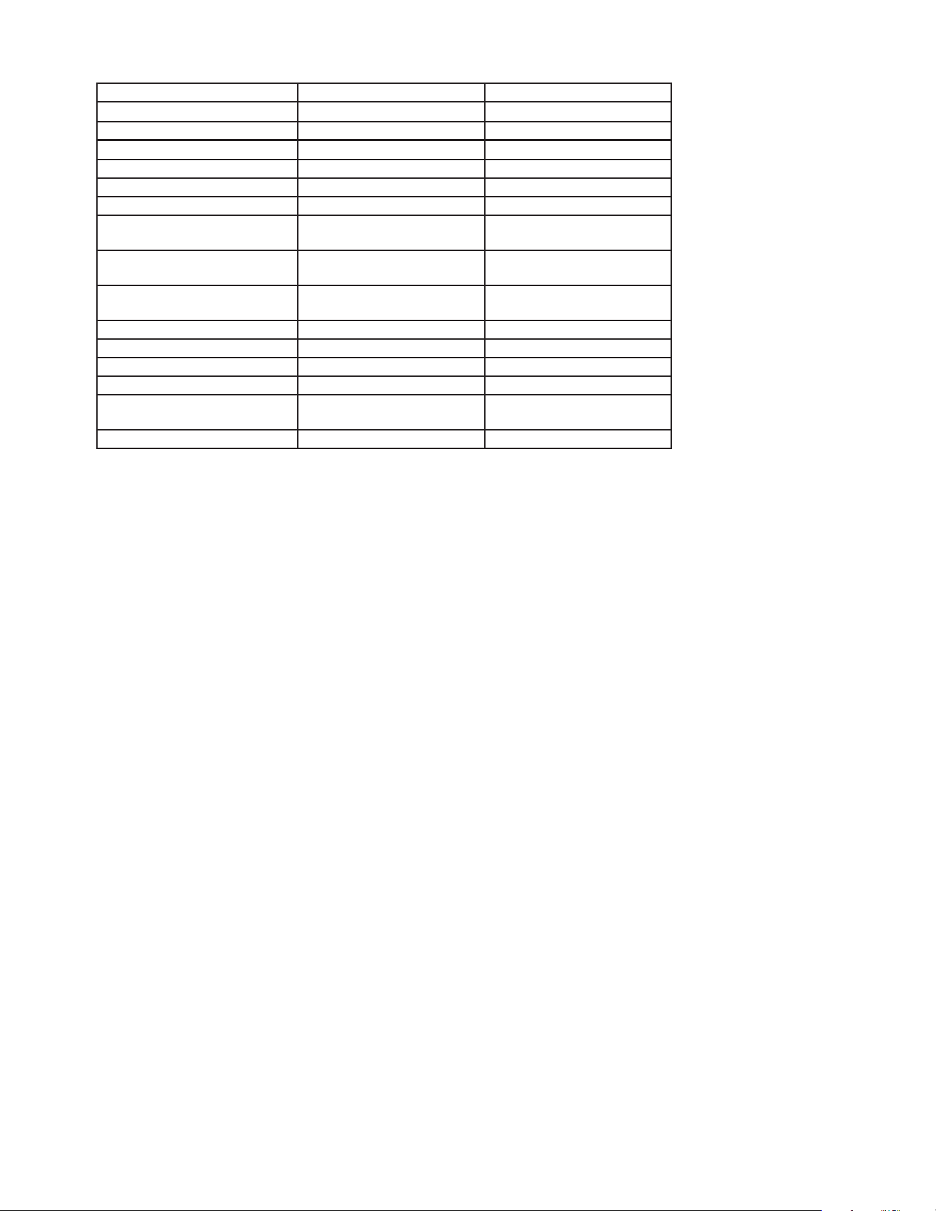
Model Number KM-930MAK2 KM-1130MAK2
AC SUPPLY VOLTAGE ~208-230/60/1 ~208-230/60/1
COMPRESSOR 208-230V 5.5RLA 35LRA 208-230V 8.3RLA 55LRA
PUMP 120V 1.2FLA 60W 120V 1.2FLA 60W
FAN 115-120V 0.9-1.0FLA 1/15 HP 115-120V 0.90FLA 1/15 HP
OTHER 115-120V 0.3A 115-120V 0.3A
MAXIMUM FUSE SIZE 20 AMPS 20 AMPS
MAX. HACR BREAKER
(USA ONLY)
20 AMPS 20 AMPS
MAX. CIRCUIT BREAKER
(CANADA ONLY)
20 AMPS 20 AMPS
MINIMUM CIRCUIT
AMPACITY
20 AMPS 20 AMPS
DESIGN PRESSURE kPa (PSI) HI-1800 (261) LO-1248 (181) HI-322 (467) LO-1724 (250)
REFRIGERANT g (oz.) R-290 395 (13.9) R-448A 1250 (44.1)
CLIMATIC CLASS 5 5
INSULATION BLOWING GAS HFO 1233zd(E) HFO 1233zd(E)
MINIMUM ROOM FLOOR
AREA m² (ft² )
18.9 (203.4) Not Applicable
HARVEST RATE ≤1,000 LB/DAY (BATCH) ≤1,000 LB/DAY (BATCH)
Note: Climatic Class 5: This appliance electrical safety tested for operation in maximum
ambient temperature of 104°F (40°C) with 40% relative humidity. However,
normal operating ambient temperature must be within 45°F to 100°F (7°C to
38°C); Normal operating water temperature must be within 45°F to 90°F (7°C to
32°C). Operation of the appliance, for extended periods, outside of these normal
temperature ranges may affect appliance performance.
11
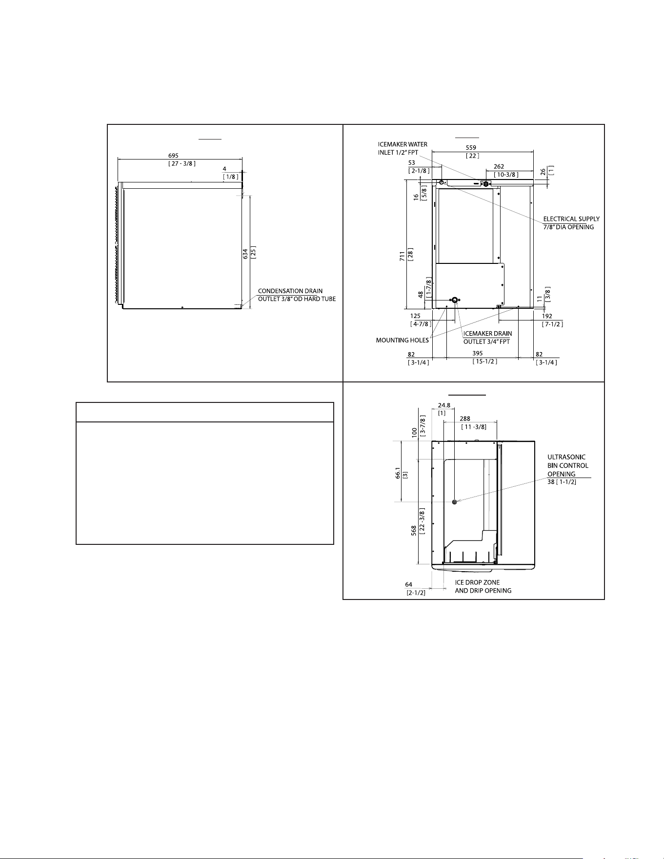
B. Dimensions/Connections
1. Air-Cooled Models (KM-322_522_622MAK)
Units: mm [in.]
Rear
Side
Bottom
NOTICE
• Allow 6" (15 cm) clearance at rear,
sides, and top for proper air circulation
and ease of maintenance and/or
service should they be required.
• The storage bin opening must
match the bottom opening as in the
illustration.
Model Shown: KM-522MAK
12
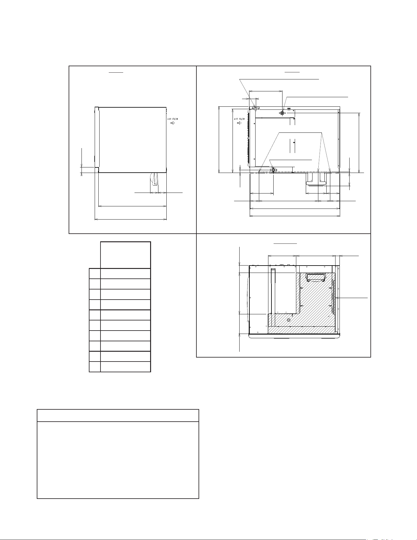
2. Air-Cooled Models (KM-330_530_730MAK)
581
[22-7/8]
72
[2-7/8]
67
[2-5/8]
613
[24-1/8]
45
[1-3/4]
Rear
Side
Bottom
KM-330MAK
KM-530MAK
KM-730MAK
A
768 [30-1/4]
B
762 [30]
C
498 [19-5/8]
D
103 [4]
E
201 [7-7/8]
F
173 [6-3/4]
G
117 [4-5/8]
H
54 [2-1/8]
I
278 [11]
J
133 [5-1/4]
ICEMAKER WATER INLET
1/2” FPT
ELECTRICAL SUPPLY OPENING
22 [7/8] DIA
ICEMAKER DRAIN
OUTLET 3/4” FPT
M5 MOUNTING
HOLES
C
24
[0.9]
80
[3-1/8]
80
[3-1/8]
A
B
D
F
G
E
10
[3/8]
507
[20]
562
[22-1/8]
541
[21-1/4]
H
I
J
330
[13]
37
[1-1/2]
237
[9-3/8]
170
[6-3/4]
61
[2-3/8]
350
[13-3/4]
ICE DROP
OPENING
Units: mm [in.]
NOTICE
• Allow 6" (15 cm) clearance at rear,
sides, and top for proper air circulation
and ease of maintenance and/or
service should they be required.
• The storage bin opening must
match the bottom opening as in the
illustration.
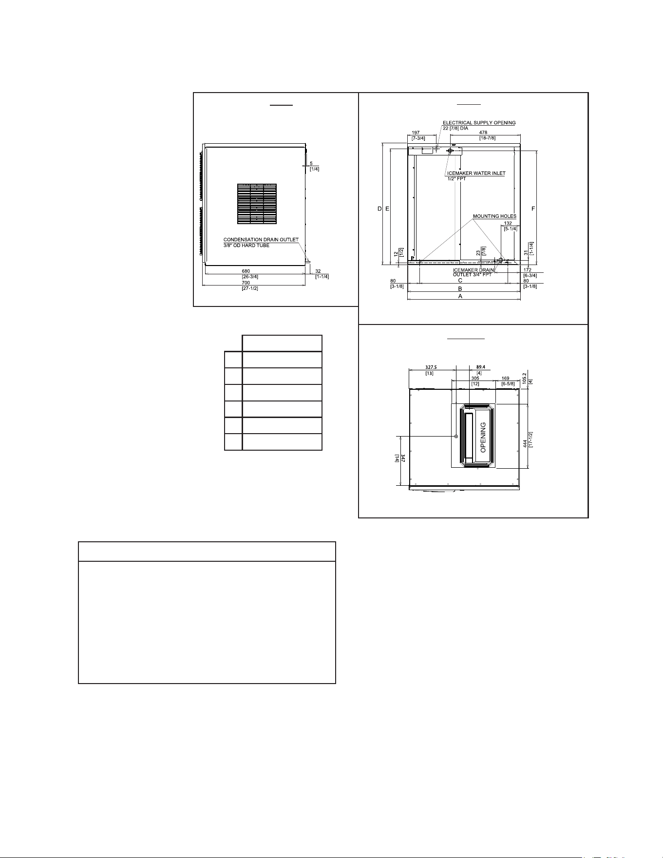
13
NOTICE
• Allow 12" (30cm) clearance at rear,
sides, and top for proper air circulation
and ease of maintenance and/or
service should they be required.
• The ice storage bin opening must
match the bottom opening as in the
illustration.
Rear
Side
Bottom
KM-930MAK2
A
768 [30-1/4]
B
762 [30]
C
602 [23-3/4]
D
827 [32-1/2]
E
786 [31]
F
775 [30-1/2]
Units: mm [in.]
3. Air-Cooled Models (KM-930MAK2 and KM-1130MAK2)
14
II. Installation Instructions
WARNING
• This appliance must be installed in accordance with applicable national, state, and
local codes and regulations.
• This appliance to be installed in accordance with the Safety Standard for
Refrigeration Systems ANSI/ASHRAE 15.
• Failure to install, operate, and maintain the appliance in accordance with this
manual will adversely affect safety, performance, component life, and warranty
coverage and may result in costly water damage.
• CHOKING HAZARD: Ensure all components, fasteners, and thumbscrews are
securely in place after installation. Make sure that none have fallen into the ice
storage bin.
15
A. Location
1. General
This appliance uses an A3 ammable refrigerant. For refrigerant charge and minimum
room oor area, see the table below.
DANGER
R-290 Class A3 Flammable Refrigerant Used
Model
R-290 Refrigerant
Charge g (oz.)
Minimum Room Floor Area
(operating or storage)
Supercie Minimale du Local
(service ou stockage)
m² (ft²); m² (pi²)
KM-322MAK 145 (5.1) 6.9 (74.7)
KM-522MAK, KM-622MAK,
KM-330MAK, KM-530MAK
150 (5.3) 7.2 (77.3)
KM-730MAK 300 (10.6) 14.4 (154.4)
KM-930MAK2 395 (13.9) 18.9 (203.4)
≥ Area m
2
(ft
2
) (see "Minimum Room Floor Area" above)
≥ Supercie m
2
(pi
2
) (voir « Supercie Minimale du Local » ci-dessus)
DANGER continued
R-290 Refrigerant Charge:
• If greater than 114 g (4 oz.), do not install in public corridor or lobby.
• If greater than 152 g (5.3 oz.), do not install within 6 m (20 ft) of open ame.
Charge de réfrigérant R-290:
• Si elle est supérieure à 114 g (4 oz.), ne pas l'installer dans un couloir public ou un
hall d'entrée.
• Si elle est supérieure à 152 g (5.3 oz.), ne pas l'installer à moins de 6 m (20 pi) d'une
amme nue.
This appliance is intended for use at altitudes up to 7,000 m (22,965 ft).

16
NOTICE
• The appliance is not intended for outdoor use. Normal operating ambient
temperature must be within 45°F to 100°F (7°C to 38°C); Normal operating water
temperature must be within 45°F to 90°F (7°C to 32°C). Operation of the appliance,
for extended periods, outside of these normal temperature ranges may affect
appliance performance.
• This appliance will not work at sub-freezing temperatures. To prevent damage to the
water supply line, drain the appliance if the air temperature is going to go below 32°F
(0°C). See "V. Preparing the Appliance for Periods of Non-Use."
• Install the appliance in a location that is at. The ice storage bin has adjustable legs,
adjust to level as needed. Be sure the appliance is properly leveled to avoid improper
operation, faulty system performance, and possible appliance damage.
• The appliance should not be located next to ovens, grills, or other high heat producing
equipment.
• The location should provide a rm and level foundation for the appliance.
• For all models except KM-930MAK2 and KM-1130MAK2, allow 6" (15 cm) clearance at
rear, sides, and top for proper air circulation and ease of maintenance and/or service
should they be required.
For KM-930MAK2 and KM-1130MAK2 models, allow 12" (30 cm) clearance at rear,
sides, and top for proper air circulation and ease of maintenance and/or service should
they be required.
B. Checks Before Installation
• Visually inspect the exterior of the shipping container and immediately report any
damage to the carrier. Upon opening the container, any concealed damage should also
be immediately reported to the carrier.
• Remove the shipping carton, tape, and packing material. If any are left in the appliance,
it will not work properly.
• See the nameplate on the rear panel, and check that your voltage supplied corresponds
with the voltage specied on the nameplate.
• Remove the panels to prevent damage when installing the appliance. See "II.C. How to
Remove Panels."
• Remove the package containing the accessories.
• Remove the protective plastic lm from the panels. If the appliance is exposed to the
sun or to heat, remove the lm after the appliance cools.
• Check that the refrigerant lines do not rub or touch lines or other surfaces, and that the
fan blade(s) (if applicable) turn freely.
• Check that the compressor is snug on all mounting pads.
• The icemaker can be installed on a dispenser unit or ice storage bin. The ice storage
bins listed below are recommended.
17
DANGER
Models utilizing R-290 refrigerant shall be used on a dispenser unit/ice storage
bin without electrical components or one designed to be used with ammable
refrigerants, and of a size or type as indicated in this manual. See the nameplate
or the Electrical and Refrigerant Data section of this manual for the refrigerant type
in your model.
Model Number Bin Width Recommended Hoshizaki Ice Storage Bin
KM-322MAK, KM-522MAK, KM-622MAK 22" or Wider BD-300 Series
KM-330MAK, KM-530MAK, KM-730MAK
KM-930MAK2, KM-1130MAK2
30" or Wider BD-500 Series
For further options, contact your local Hoshizaki distributor.
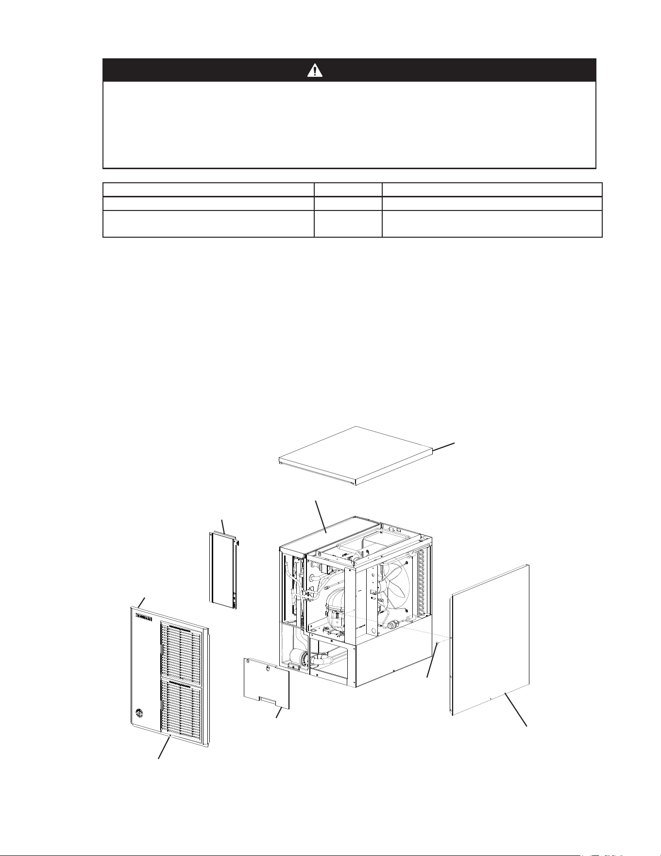
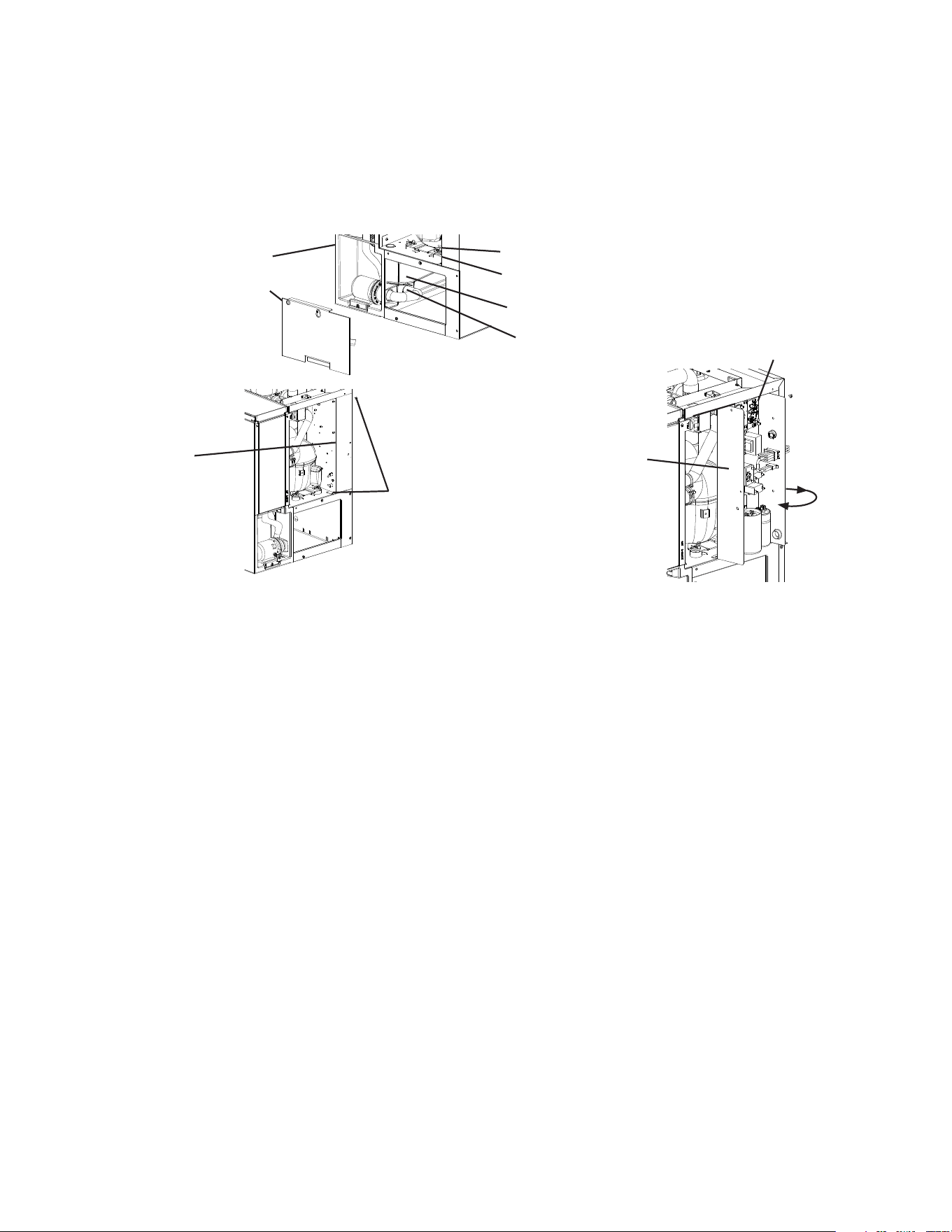
C. How to Remove Panels
See Fig. 1
• Front Panel: Remove the screw. Lift up and towards you.
• Top Panel: Lift up at front slightly, push rearward, then lift off.
• Right Side Panel: Remove the screw. Slide forward slightly and lift off.
• Top Insulation Panel: Pull forward slightly, then lift off.
• Front Insulation Panel: From the top, pull forward slightly, then lift off.
Fig. 1
Top Panel
Front Insulation Panel
Front
Panel
Base Cover
Screw
Right Side Panel
Screw
Model Shown: KM-522MAK
Top Insulation Panel
18
Bolts
D. Dispenser Unit/Ice Storage Bin and Icemaker Setup
DANGER
Models utilizing R-290 refrigerant shall be used on a dispenser unit/ice storage
bin without electrical components or one designed to be used with ammable
refrigerants, and of a size or type as indicated in this manual. See the nameplate or
the Electrical and Refrigerant Data section of this manual for the refrigerant type in
your model.
WARNING
• The installer must ensure the dispenser unit/ice storage bin is compatible with the
icemaker, and the dispenser unit/ice storage bin and icemaker are properly attached
and secured.
• Do not allow top kits to interfere with the bin control lens sensing area or the
icemaker will not operate properly.
1a) Dispenser Unit: Follow the dispenser unit's setup procedure.
1b) Ice Storage Bin: Unpack the ice storage bin and attach the 4 adjustable legs provided
(bin accessory) to the bottom of the ice storage bin.
2) Position the dispenser unit/ice storage bin in its permanent location.
3) If required, install an adapter kit or top kit. Contact your local Hoshizaki distributor for
recommendations.
4) Level the dispenser unit/ice storage bin in both the left-to-right and front-to-rear
directions. Ifusing an ice storage bin, adjust the ice storage bin legs to level.
5) Place the icemaker on top of the dispenser unit/ice storage bin.
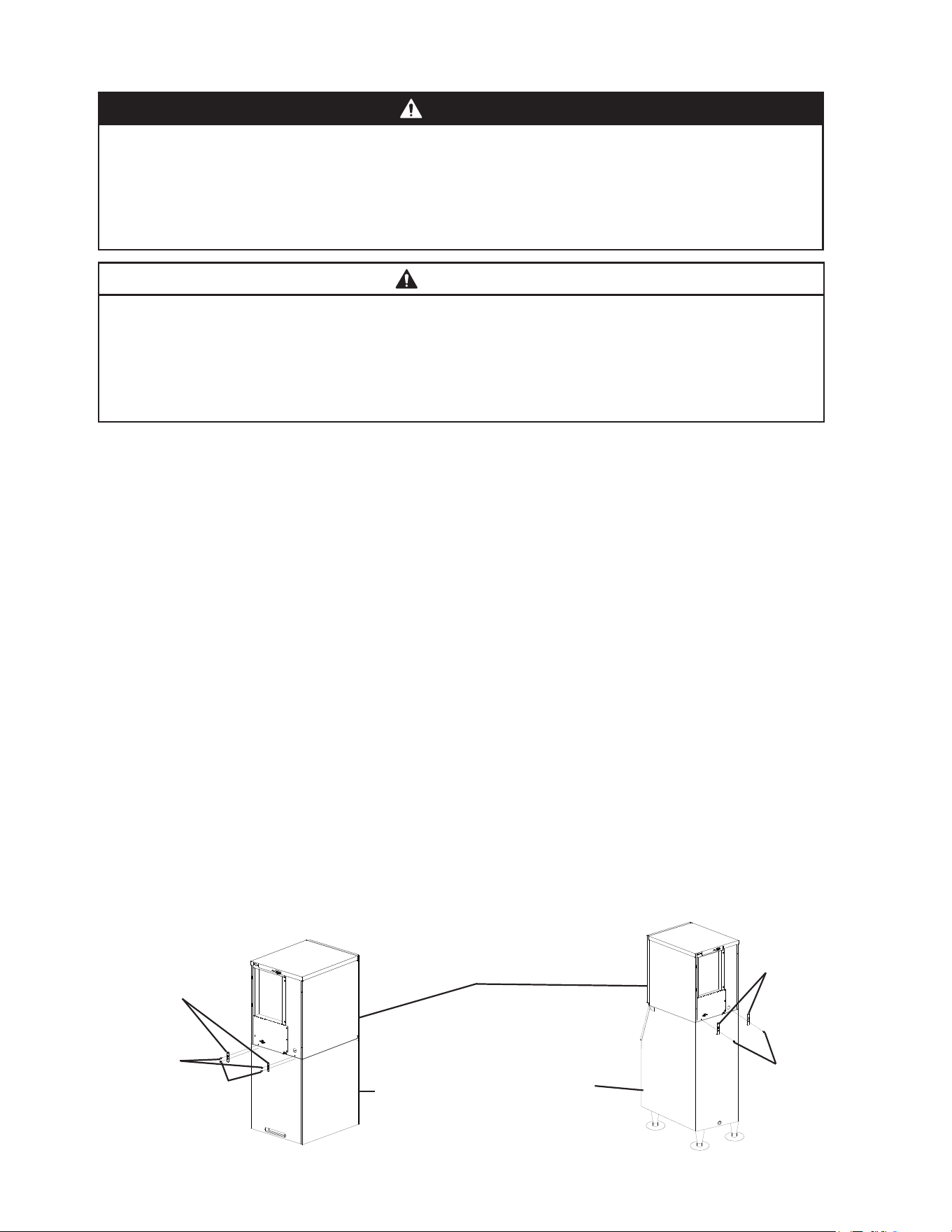
6a) Dispenser Unit: Follow the dispenser unit, adapter kit, or top kit instructions for
securing the icemaker. If no instructions are available, secure the icemaker using the
mounting brackets provided. Rotate the mounting brackets so that they t ush to the
dispenser unit. SeeFig.2a. Secure the mounting brackets to the icemaker with the bolts
provided. Secure the mounting brackets to the dispenser unit with self-tapping screws
(not provided). NOTICE! Use care to avoid damage to dispenser unit components
when attaching the mounting brackets. For dispenser unit bin control setting,
see "III.B.1. Bin Control Setting."
6b) Ice Storage Bin: Follow the ice storage bin, adapter kit, or top kit instructions for
securing the icemaker. If no instructions are available, secure the icemaker using the
2mounting brackets and the bolts provided. See Fig.2b.
Fig. 2a
Fig. 2b
Dispenser
Unit
Self-Tapping Screws
(Not Provided)
Mounting
Brackets
Model Shown: KM-522MAK
Icemaker
Ice
Storage
Bin
Mounting
Brackets
Bolts
19
E. Electrical Connection
WARNING
For All Models
• Electrical connection must be hard-wired and must meet national, state, and local
electrical code requirements. Failure to meet these code requirements could result
in death, electric shock, serious injury, re, or damage.
• The appliance requires an independent power supply of proper capacity. See
the nameplate for electrical specications. Failure to use an independent power
supply of proper capacity can result in a tripped breaker, blown fuse, damage to
existing wiring, or component failure. This could lead to heat generation or re.
• THE APPLIANCE MUST BE GROUNDED. Failure to properly ground the
icemaker could result in death or serious injury.
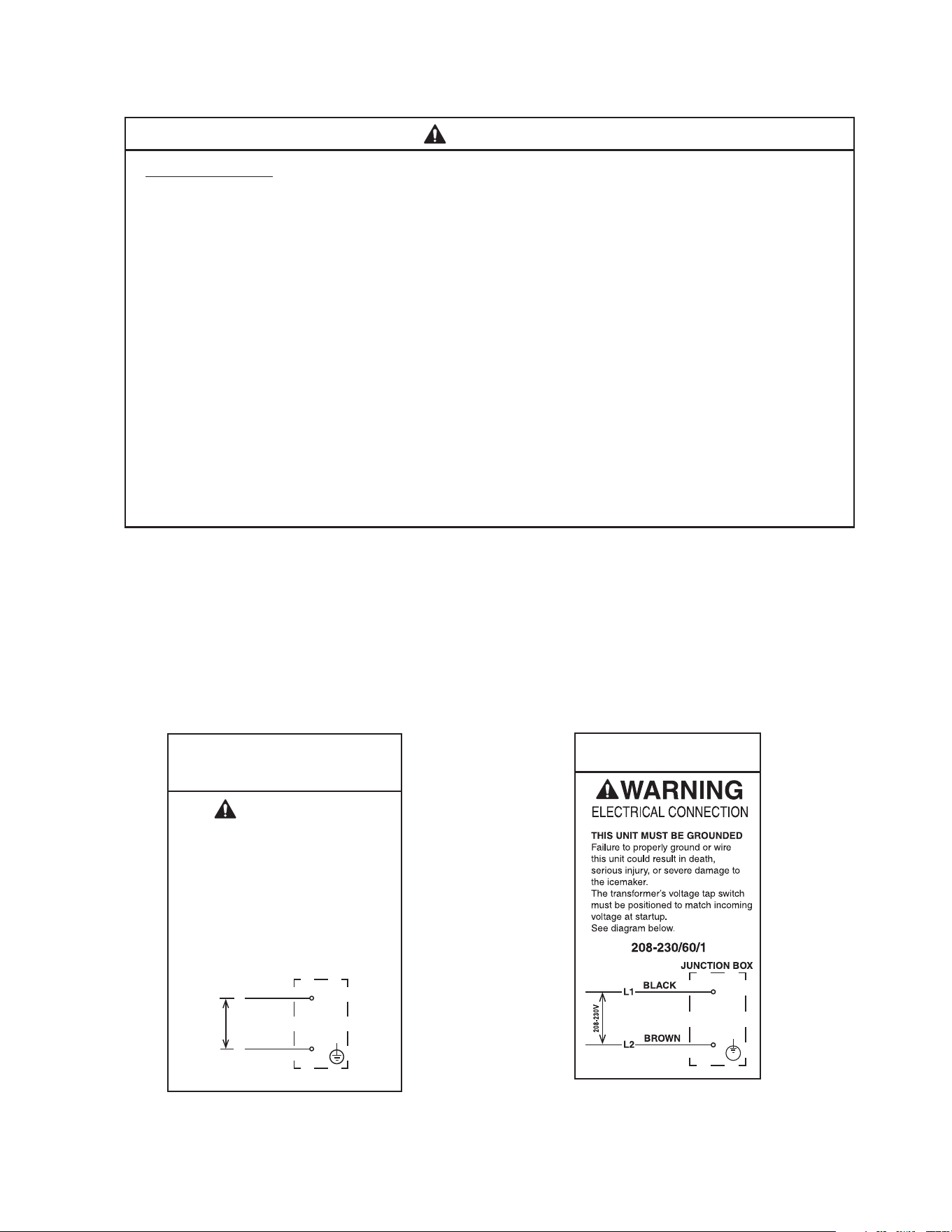
• Electrical connection must be made in accordance with the instructions on the
"WARNING" tag, provided with the pig tail leads in the junction box. See Figs. 3a
and 3b.
• To reduce the risk of electric shock, do not touch the control switch or mode switch
with damp hands.
• Usually an electrical permit and services of a licensed electrician are required.
• The maximum allowable voltage variation is ±6 percent of the nameplate rating.
• The opening for the power supply connection is 7/8" DIA. to t a 1/2" trade size conduit.
• On 115VAC models, the white lead must be connected to the neutral conductor of the
power source. NOTICE! Miswiring may result in severe damage to the icemaker.
• NOTICE! On KM-930MAK2 and KM-1130MAK2 models, the main transformer’s
voltage tap switch must be positioned to match incoming voltage at startup.
KM-322MAK, KM-330MAK
KM-522MAK, KM-530MAK
KM-622MAK, KM-730MAK
115/60/1
WARNING
ELECTRICAL CONNECTION
THIS UNIT MUST BE GROUNDED
Failure to properly ground or wire
this unit could result in death,
serious injury, or severe damage
to the icemaker. The white lead
must be connected to the neutral
conductor of the power source.
See diagram below.
4Axxxx-010Based on 435005
JUNCTION BOX
1
15-120V
Black
WHITE
L
N
Fig. 3a
KM-930MAK2
KM-1130MAK2
Fig. 3b
20
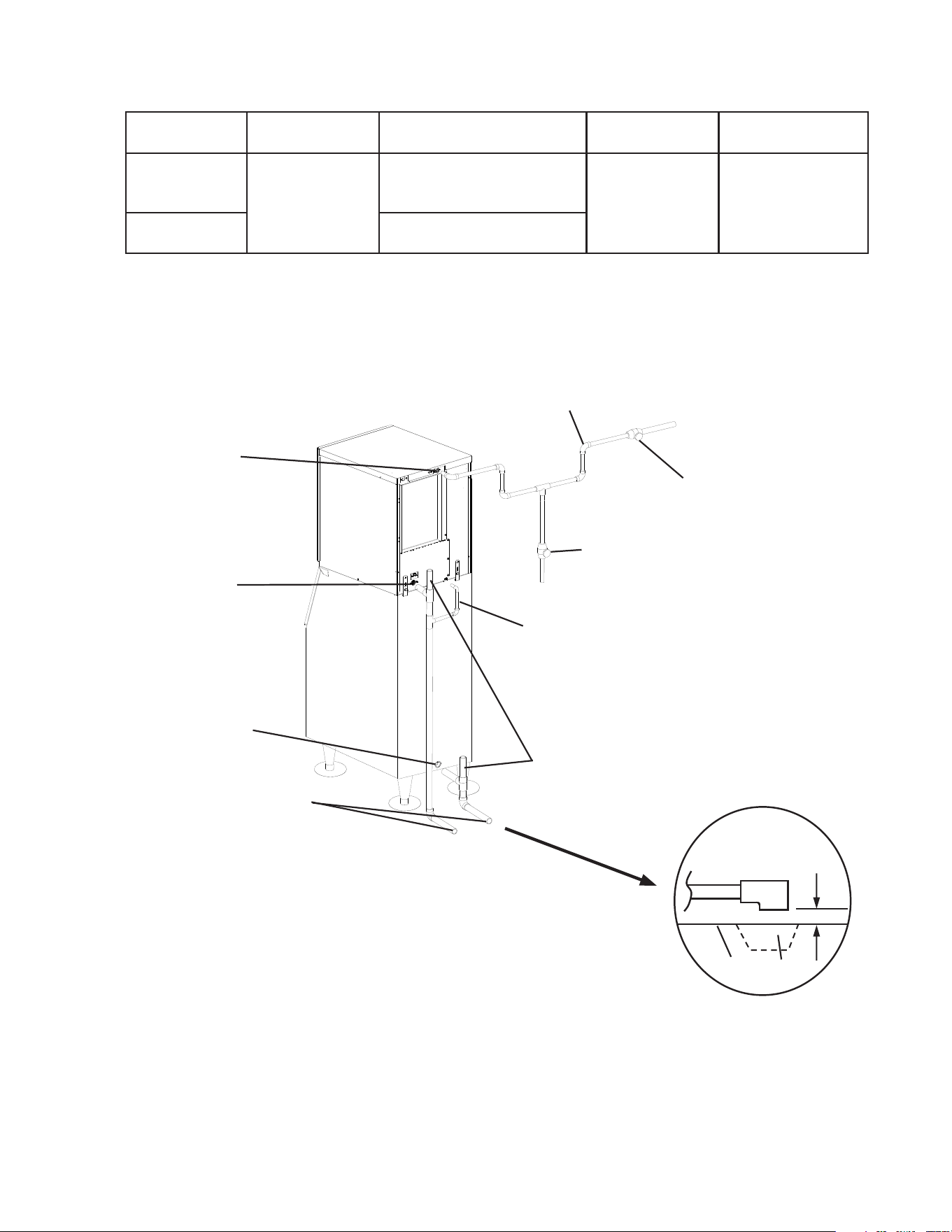
F. Water Supply and Drain Connections
See Fig. 4
WARNING
• Water supply and drain connections must be installed in accordance with applicable
national, state, and local regulations.
• Connect to potable water supply only. Do not connect to a hot-water supply.
NOTICE
• Water supply line size is critical to the operation of the appliance. Failure to provide
adequate water supply to the appliance may result in damage to the appliance,
damage to property, and may void the warranty.
• Normal operating water temperature must be within 45°F to 90°F (7°C to 32°C).
Operation of the appliance, for extended periods, outside of this normal temperature
range may affect appliance performance.
• Water supply pressure must be a minimum of 10 PSIG (68 kPaG) and a maximum
of 113PSIG (779 kPaG). If the pressure exceeds 113 PSIG (779 kPaG), the use of a
pressure reducing valve is required.
• External lters, strainers, or softeners may be required depending on water quality.
Contact your local Hoshizaki Certied Service Representative or local Hoshizaki
distributor for recommendations.
• In areas where water damage is a concern, install in a contained area with a oor
drain.
• Water line installation to the appliance is not warranted by Hoshizaki.
• Be sure there is sufficient extra water supply line and drain line for the appliance to be
pulled out for service.
• Water-hammer issues must be resolved by a qualied plumber before installing the
appliance. Water hammer can cause appliance damage that may lead to water
leakage or ooding.
• A minimum of 3/4" nominal ID hard pipe or equivalent is required for the drain line.
Installing a smaller diameter drain line will reduce water ow and may lead to water
leakage or ooding.
• To prevent damage to the appliance, do not operate the appliance when the
water supply is off, or if the pressure is below 10 PSIG (68 kPaG). Do not run the
appliance until the proper water pressure is reached.
• A plumbing permit and services of a licensed plumber may be required in some areas.
• The icemaker drain line, dispenser unit/ice storage bin drain line, and water-cooled
condenser drain line (if applicable) must be run separately.
• Drain lines must have 1/4" fall per foot (2 cm per 1 m) on horizontal runs to provide a
proper drain ow. A vented tee connection is also required for proper ow.
• Drain lines should not be piped directly to the sewer system. An air gap of a minimum
of 2vertical inches (5 cm) should be between the end of the drain pipes from the
icemaker, dispenser unit/ice storage bin, and water-cooled condenser (if applicable)
and the oor drain.
21
1. Icemaker
MODEL Icemaker Water
Supply Inlet
Minimum Icemaker Water
Supply Line Size
Icemaker Drain
Outlet
Minimum Icemaker
Drain Line Size
All Except
KM-930MAK2
KM-1130MAK2
1/2" Female Pipe
Thread (FPT)
1/4" Nominal ID Copper
Water Tubing or Equivalent
3/4" Female Pipe
Thread (FPT)
3/4" Nominal
ID Hard Pipe or
Equivalent
KM-930MAK2
KM-1130MAK2
3/8" Nominal ID Copper
Water Tubing or Equivalent
• A water supply line shut-off valve and drain valve must be installed.
Fig. 4
Air-Cooled Models
Icemaker
Water Supply
Inlet
1/2" FPT
Icemaker
Drain Outlet
3/4" FPT
Vent Tube
Bin Drain Outlet
3/4" FPT
Minimum 3/4" Nominal ID
Hard Pipe or Equivalent
All Except KM-930MAK2 and KM-1130MAK2:
Minimum 1/4" Nominal ID Copper Water Tubing or
Equivalent.
KM-930MAK2 and KM-1130MAK2: Minimum 3/8"
Nominal ID Copper Water Tubing or Equivalent.
Be sure there is sufficient
extra water supply line and
drain line for the appliance
to be pulled out for service.
Separate piping to approved
drain. Leave a 2" (5 cm)
vertical air gap between the
end of each pipe and the
drain.
2" (5 cm) air gap
Floor
Drain
Shut-Off Valve
Drain Valve
Icemaker
Condensation
Drain Outlet
3/8" OD Hard Tube
Model Shown: KM-522MAK
22
G. Final Checklist
1. Pre-Startup
1) Is the appliance level?
2) Is the appliance in a site where the ambient temperature is within 45°F to 100°F (7°C to
38°C) and the water temperature within 45°F to 90°F (7°C to 32°C) all year around?
3) For all models except KM-930MAK2 and KM-1130MAK2, is there at least 6" (15 cm)
clearance at rear, sides, and top of the appliance?
For KM-930MAK2 and KM-1130MAK2 models, is there at least 12" (30cm) clearance at
rear, sides, and top of the appliance?
4) Have the shipping carton, tape, and packing material been removed from the
appliance? Are the cube guide(s) in their correct positions?
5) Hasthe protective plastic lm been removed from the panels?
6) Have all electrical and water connections been made? Do electrical and water
connections meet applicable national, state, and local code and regulation
requirements?
7) Has the power supply voltage been checked or tested against the nameplate rating?
Has a proper ground been installed to the appliance? Has the KM-930MAK2 and
KM-1130MAK2 models main transformer’s voltage tap switch been positioned to
match incoming voltage.
8) Are the water supply and drain lines sized as specied? Are the water supply line
shut-off valve(s) and drain valve(s) installed? Has the water supply pressure been
checked to ensure a minimum of 10 PSIG (68 kPaG) and a maximum of 113 PSIG
(779 kPaG)?
9) Is the compressor snug on all mounting pads? Have the refrigerant lines been checked
to make sure they do not rub or touch other lines or surfaces? Have the fan blade(s)
(if applicable) been checked to make sure they turn freely?
10) Continue to "III. Operating Instructions."
2. Post-Startup
WARNING
CHOKING HAZARD: Ensure all components, fasteners, and thumbscrews
are securely in place after installation. Make sure that none have fallen into the
dispenser unit/ice storage bin.
1) Has the bin control been set to the proper setting for the application?
2) Has the bin control operation been conrmed?
3) Are all components, fasteners, and thumbscrews securely in place?
4) Has the end user been given the instruction manual, and instructed on how to operate
the appliance and the importance of the recommended periodic maintenance?
5) Has the end user been given the contact information of an authorized service agent?
6) Has the warranty registration been completed and submitted to the factory?
23
III. Operating Instructions
Models covered in this manual utilize either R-290 or R-448A refrigerant.
R-290 Class A3 Flammable Refrigerant Used*
DANGER
Risk of Fire or Explosion. Flammable Refrigerant Used.*
• Be sure to follow all Important Safety Information located at the beginning of this
manual.
• Failure to install, operate, and maintain the appliance in accordance with this manual
will adversely affect safety, performance, component life, and warranty coverage and
may result is costly water damage.
• Keep clear of obstruction all ventilation openings in the appliance enclosure or in the
structure for building-in.
Risque D'Incendie ou D'Explosion. Fluide Frigorigène Inammable Utilisé.*
• Veillez à respecter toutes les consignes de sécurité importantes gurant au début de
ce manuel.
• Le fait de ne pas installer, utiliser et entretenir l'appareil conformément à ce manuel
aura des conséquences négatives sur la sécurité, les performances, la durée de vie
des composants et la couverture de la garantie, et peut entraîner des dégâts des
eaux coûteux.
• Ne pas obstruer les ouvertures de ventilation dans l'enceinte de l'appareil ou dans la
structure d'encastrement.
A. Important Notes About Usage
NOTICE
• Protect the oor when moving the appliance to prevent damage to the oor.
• Do not leave the appliance on during extended periods of non-use, extended
absences, or in sub-freezing temperatures. To properly prepare the appliance for
these occasions, follow the instructions in "V. Preparing the Appliance for Periods of
Non-Use."
• Do not place objects on top of the appliance.
• The dispenser unit/ice storage bin is for ice use only. Do not store anything else in the
dispenser unit/ice storage bin.
• If applicable, keep ventilation openings in the appliance clear of obstruction.
*This statement applies to models utilizing R-290 refrigerant. See the nameplate or the
Electrical and Refrigerant Data section of this manual for the refrigerant type in your
model.
*Cette déclaration s’applique aux modèles utilisant le réfrigérant R-290. Consultez la
plaque signalétique ou la section Données électriques et de réfrigérant de ce manuel
pour connaître le type de réfrigérant de votre modèle.
24
B. Startup
1. Bin Control Setting
An ultrasonic sensor is used as the bin control to control the level of ice in the dispenser
unit/ice storage bin. The bin control setting must be set to match the application to avoid
possible icemaker movement, water leakage, or ice overow.
DANGER
Models utilizing R-290 refrigerant shall be used on a dispenser unit/ice storage
bin without electrical components or one designed to be used with ammable
refrigerants, and of a size or type as indicated in this manual. See the nameplate or
the Electrical and Refrigerant Data section of this manual for the refrigerant type in
your model.
WARNING
• All parts are factory-adjusted. Improper adjustments may adversely affect safety,
performance, component life, and warranty coverage.
• To reduce the risk of electric shock, do not touch the control switch or mode switch
with damp hands.
• Improper adjustment may adversely affect safety, performance, component life, and
warranty coverage.
• On dispenser unit applications, do not increase ice level above the recommended
setting listed below. Higher ice levels could result in icemaker movement, water
leakage, or ice overow.
• Risk of electric shock. Control switch in "OFF" position does not de-energize all
loads. Note: On KM-930MAK2 models fan motor runs with control switch in the
"OFF" position. Disconnect or breaker must be turned off to de-energize fan motor.
NOTICE
• If the appliance is turned off, wait for at least 3 min. before restarting the appliance to
prevent damage to the compressor.
• At startup, conrm that all internal and external connections are free of leaks.
• Do not allow top kits or top kit risers (if applicable) to interfere with the bin control
lens sensing area or the icemaker will not operate properly.
25
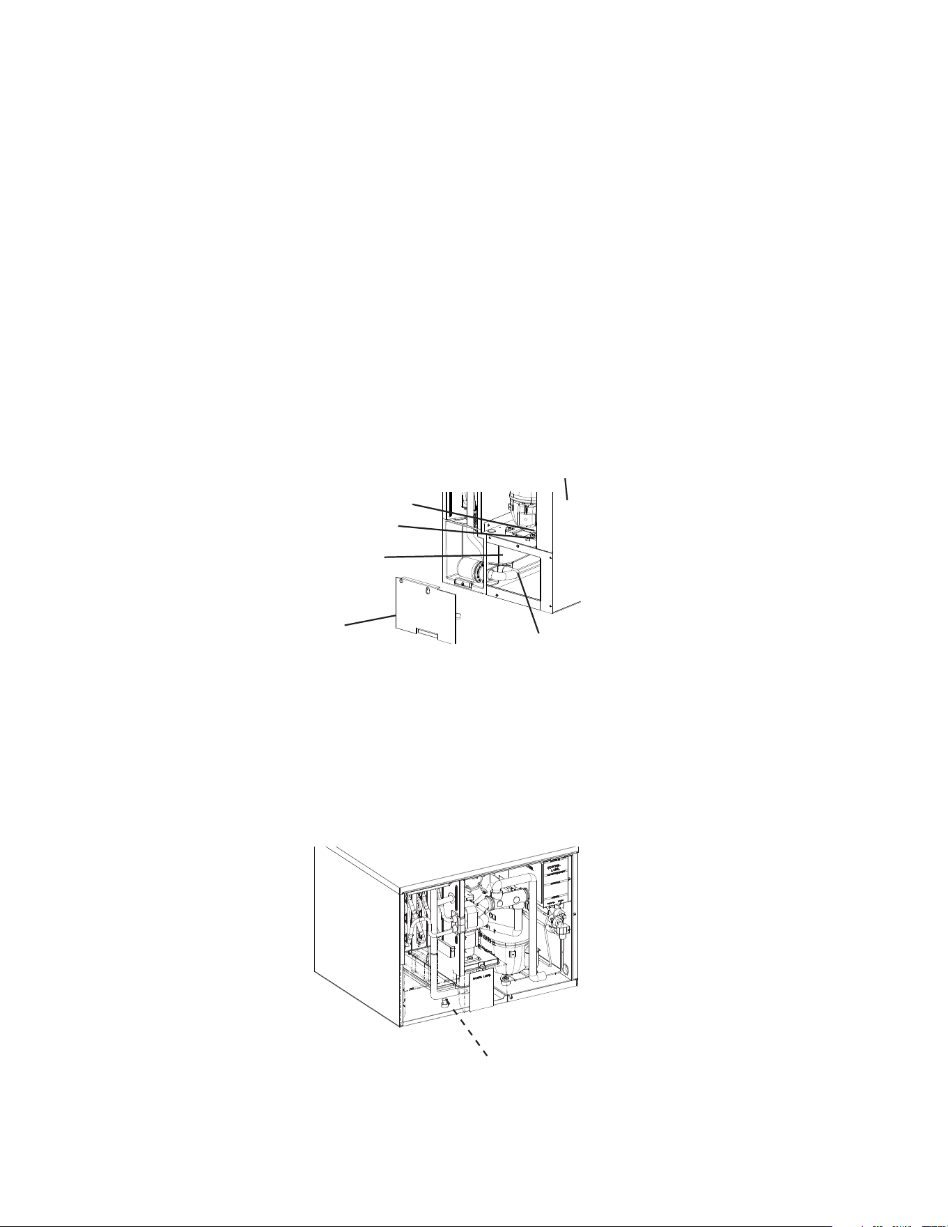
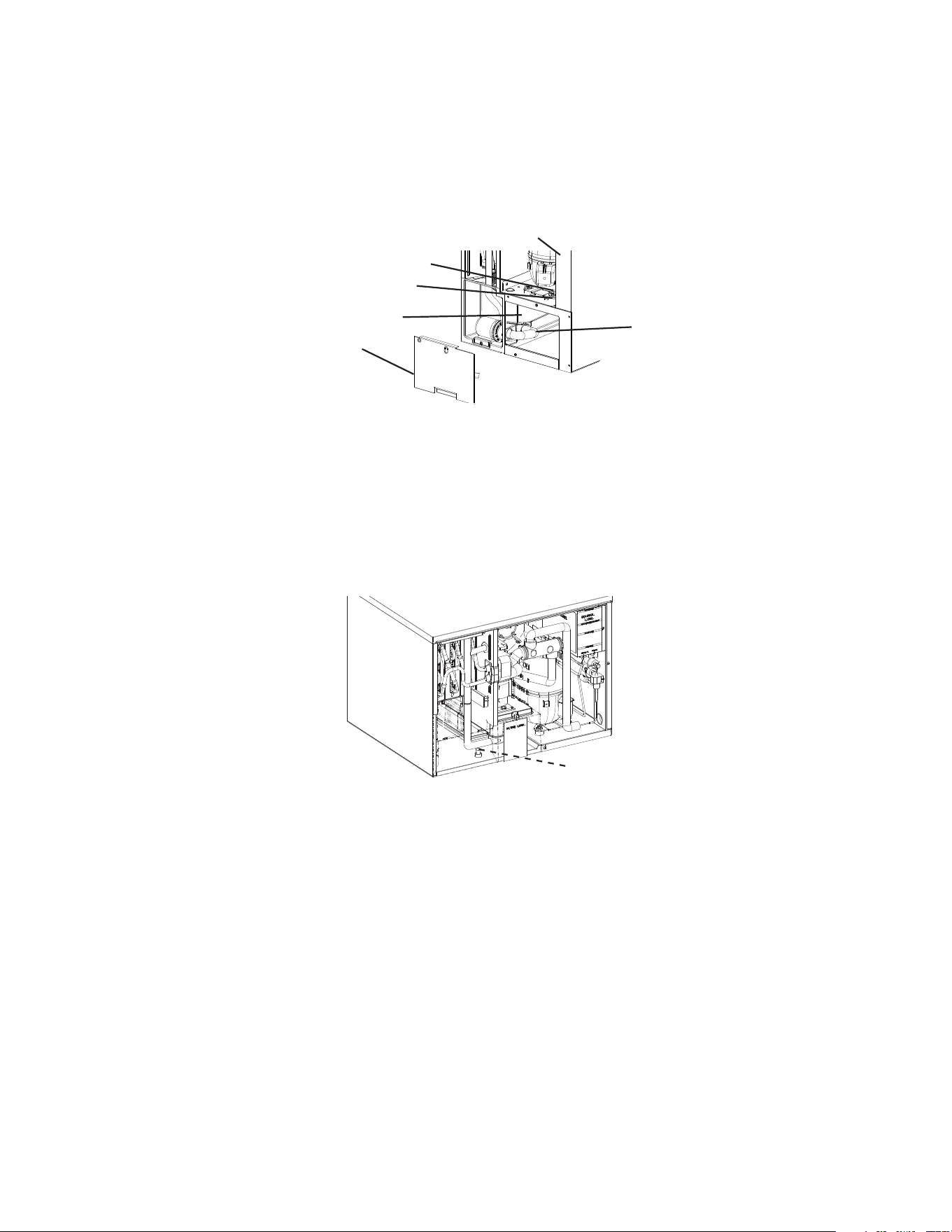
1) Move the control switch to the "OFF" position. Make sure the power supply is off to the
icemaker. If not already removed, remove the top panel and control box cover.
Note: For KM-322_522_622MAK also remove the base cover. See Fig. 5. If front access
to the control box is required, remove the control box mounting screws, then slide the
control box forward and rotate the control box for access. See Fig. 6.
Icemaker
Base Cover
Disconnect This
End of Pump Tubing
to Drain Water Tank
Fig. 5
Control Switch
Mode Switch
Water Tank
Fig. 6
Control Box
Control Box
Mounting Screws
Control Box
Control Board
2) Conrm the correct control board bin control setting required for your application and
adjust according to the following tables. See Fig. 7 through Fig. 10.
26
For Standard Ice Storage Bins, Hoshizaki DB and DM Dispenser Units, and Coca-Cola
Freestyle
®
Dispenser Units. See Figs. 7 and 8.
Application Bin Control Ice Level Settings
Bin Control Setting
Shutdown Distance From Ultrasonic Bin Control Lens
(Restart is 4 in. (102 mm) below shutdown distance)
Standard Ice Storage Bins 1
(Factory Default)
304 mm (12")
Do not adjust dispensers to this setting.
Hoshizaki DB and DM Dispensers 2 335 mm (13")
Coca-Cola Freestyle
®
Dispensers 3 416 mm (16 3/8")
Optional Setting 4 522 mm (20.5")
5 610 mm (24")
WARNING
Conrm that the nal ice level location does not allow for icemaker movement, water
leakage, or ice overow.
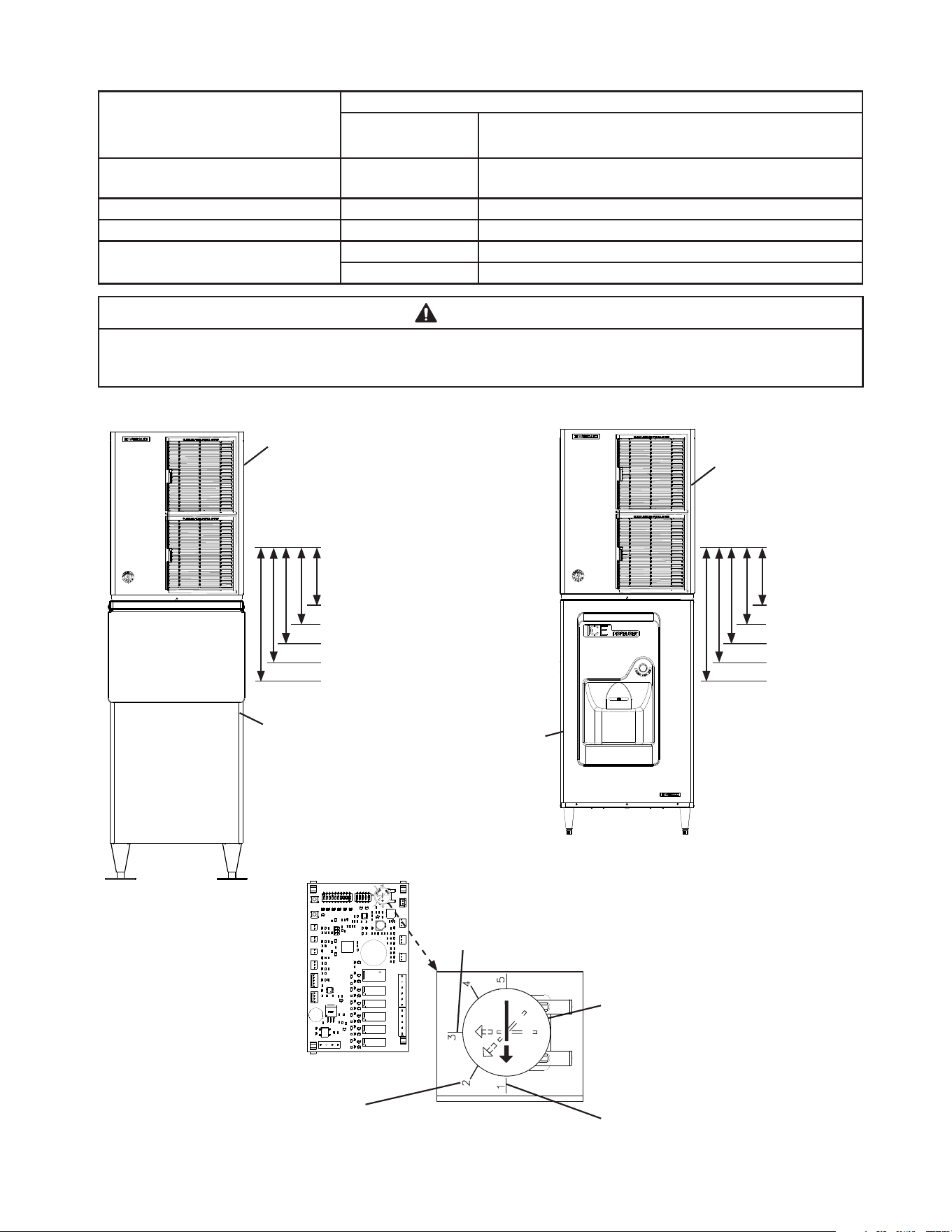
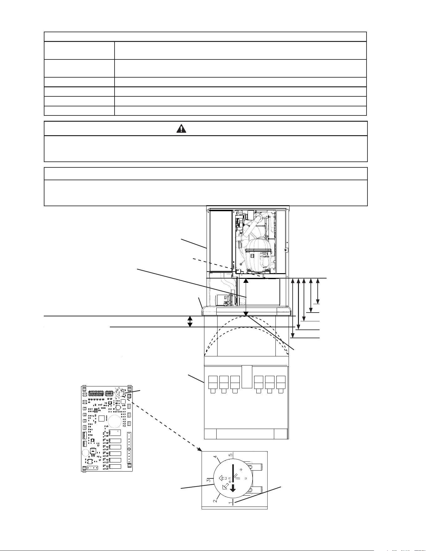
a) KM-322_522_622MAK. See Fig. 7.
Fig. 7
Control Board
Recommended Setting for
Hoshizaki DB and DM Dispensers
Recommended Setting for Coca-Cola Freestyle®
Dispensers
Icemaker
Hoshizaki DB-200H
Dispenser Unit
Model Shown:
KM-622MAK with DB-200H
Model Shown:
KM-622MAK with BD-300SF
Icemaker
Standard Ice
Storage Bin
Turn dial to adjust to proper setting
Factory Default for Standard
Ice Storage Bins
WARNING! Do not use this
setting with dispensers.
Bin Control
Lens
Setting #1
Setting #3
Setting #4
Setting #5
Setting #2
Bin Control
Lens
Setting #1
Setting #3
Setting #4
Setting #5
Setting #2
27
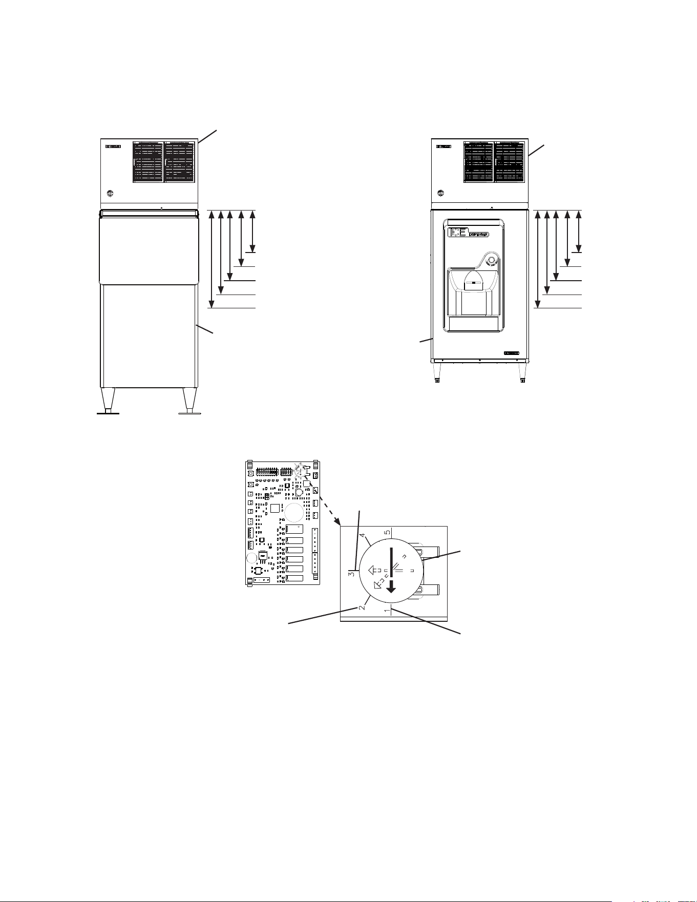
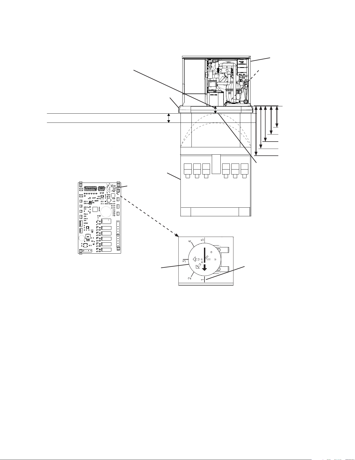
Fig. 8
Control Board
Recommended Setting for
Hoshizaki DB and DM Dispensers
Recommended Setting for Coca-Cola Freestyle®
Dispensers
Icemaker
Hoshizaki DB-200H
Dispenser Unit
Model Shown:
KM-530MAK with DB-200H
Model Shown:
KM-530MAK with BD-500SF
Icemaker
Standard Ice
Storage Bin
Turn dial to adjust to proper setting
Factory Default for Standard
Ice Storage Bins
WARNING! Do not use this
setting with dispensers.
Bin Control
Lens
Setting #1
Setting #3
Setting #4
Setting #5
Setting #2
Bin Control
Lens
Setting #1
Setting #3
Setting #4
Setting #5
Setting #2
b) KM-330_530_730MAK, KM-930MAK2, and KM-1130MAK2. See Fig. 8.
28
For Non-Hoshizaki Dispenser Units. See Figs 9 and 10.
Bin Control Ice Level Settings
Bin Control Setting
Shutdown Distance From Bin Control Lens
(Restart is 4 in. (102 mm) below shutdown distance)
1
(Factory Default)
304 mm (12")
Do not adjust dispensers to this setting.
2 335 mm (13")
3 416 mm (16 3/8")
4 522 mm (20.5")
5 610 mm (24")
WARNING
Conrm that the nal ice level location does not allow for icemaker movement,
water leakage, or ice overow.
NOTICE
The ice level must be lower than the top of the dispenser unit. Also, be sure the top
kit or top kit riser (if applicable) are clear from the bin control lens sensing area.
a) KM-322_522_622MAK. See Fig. 9.
Fig. 9
Full Bin Measured Distance
(Shutdown Distance)
Measure from the bottom of
the compressor base (bin
control lens) to the preferred
full bin level of ice; refer to the
dispenser instruction manual.
Icemaker Restart Level
(4" (102 mm) below preferred
full bin level of ice)
Set Bin Control Setting at or Below Maximum Full
Bin Level of Ice (Shutdown Position) Shown Here
Top Kit
Icemaker
Non-Hoshizaki
Dispenser Unit
Bin Control Setting
Bin Control Lens
Control Board
Factory Default for Standard
Ice Storage Bins
WARNING! Do not use this
setting with dispensers.
Turn dial to adjust to setting
that matches Full Bin Measured
Distance (Shutdown Distance)
Bin Control
Lens
Setting #1
Setting #3
Setting #4
Setting #5
Setting #2
Maximum Full Bin Level of
Ice (Shutdown Position).
WARNING! Do not adjust
bin control setting above
this level.
Model Shown: KM-622MAK
29
Fig. 10
Full Bin Measured Distance
(Shutdown Distance) Measure from
the bottom of the compressor base
(bin control lens) to the preferred
full bin level of ice; refer to the
dispenser instruction manual.
Icemaker Restart Level
(4" (102 mm) below preferred
full bin level of ice)
Set Bin Control Setting at or Below Maximum Full
Bin Level of Ice (Shutdown Position) Shown Here
Top Kit
Icemaker
Non-Hoshizaki
Dispenser Unit
Bin Control Setting
Bin Control Lens
Control Board
Factory Default for Standard
Ice Storage Bins
WARNING! Do not use this
setting with dispensers.
Turn dial to adjust to setting
that matches Full Bin Measured
Distance (Shutdown Distance)
Bin Control
Lens
Setting #1
Setting #3
Setting #4
Setting #5
Setting #2
Maximum Full Bin Level of
Ice (Shutdown Position).
WARNING! Do not adjust
bin control setting above
this level.
Model Shown: KM-530MAK
b) KM-330_530_730MAK, KM-930MAK2, and KM-1130MAK2. See Fig. 10.
30
2. Appliance Startup and Bin Control Check
WARNING
• All parts are factory-adjusted. Improper adjustments may adversely affect safety,
performance, component life, and warranty coverage.
• Make sure the icemaker has been installed as outlined in this manual and that
the water supply is on.
• Improper adjustment may adversely affect safety, performance, component life,
and warranty coverage.
NOTICE
• If the icemaker is turned off, wait for at least 3 minutes before restarting the
icemaker to prevent damage to the compressor.
• To prevent damage to the water pump seal, do not leave the control switch in the
"PUMP" position for extended periods when the water tank is empty.
• At startup, conrm that all internal and external connections are free of leaks.
• Do not allow top kits or top kit risers (if applicable) to interfere with the bin control
lens sensing area or the icemaker will not operate properly.
1) If not already removed, remove the front and top panels and control box cover.
Make sure the bin control setting has been adjusted as outlined in "III.B.1. Bin Control
Setting."
2) Make sure the control switch is in the "OFF" position and that the power supply is off.
3) Open the water supply line shut-off valve(s).
4) Move the mode switch on the control box to the "ICE" position, then move the control
switch to the "ON" position. Turn on the power supply, and allow the icemaker to
operate.
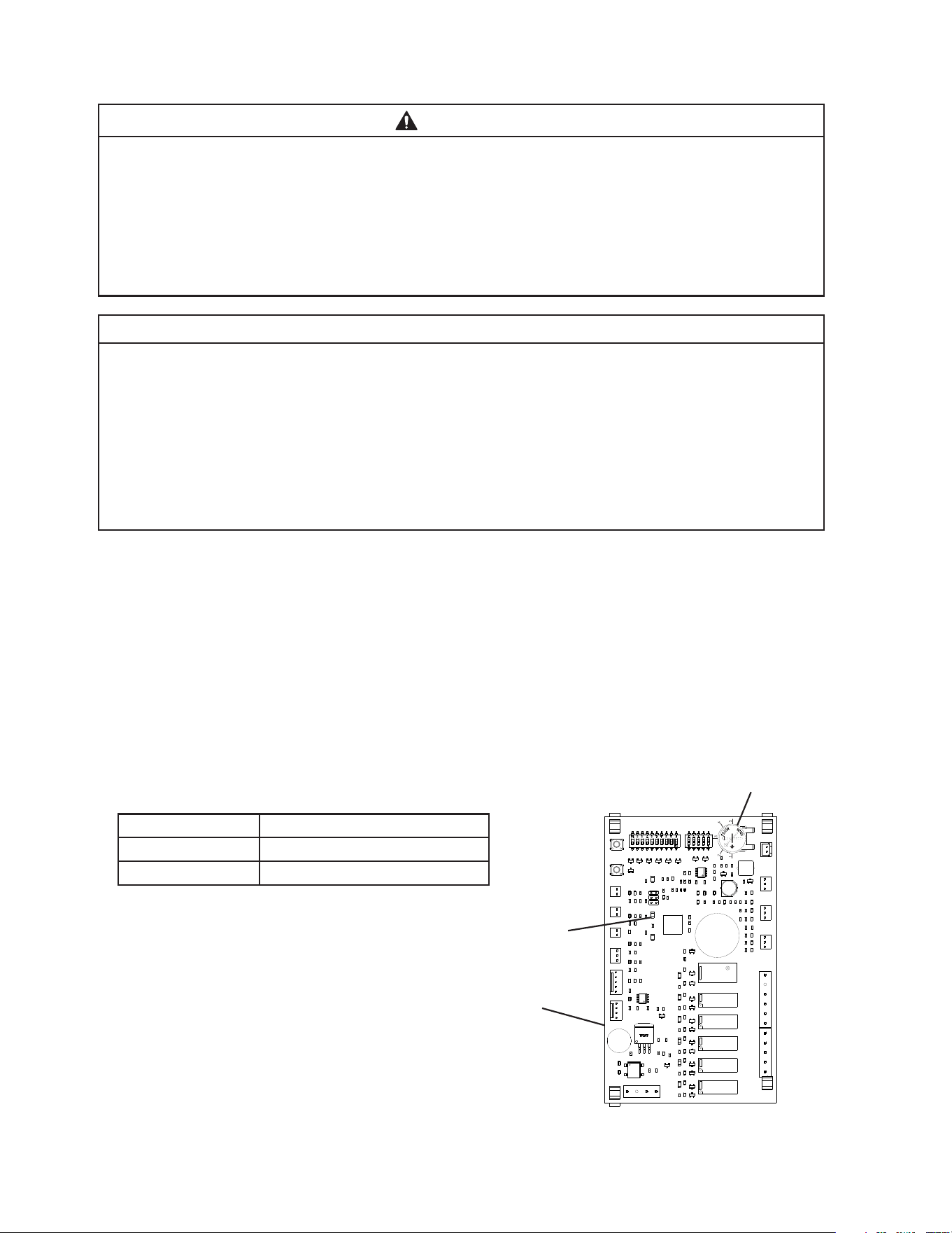
5) Conrm the control board "BIN CLS"
LED is off (bin empty). See Fig. 11.
Ice Level in Bin Control Board "BIN CLS" LED
Empty OFF
Full ON
6) If the control board "BIN CLS" is on
(indicating a full bin), correct any
interference from the top kit or top kit
riser (if applicable).
Control Board
BIN CLS LED
Bin Control Setting
Fig. 11
31
7) 1 min. ll cycle begins. Place an object 5" to 7" (127 to 178mm) away from the bin
control lens. See Figs. 12a, 12b, and 12c. 15 sec. later, the icemaker shuts down.
Remove the object from the bin control lens. 30sec. later, the icemaker restarts.
For bin control shutdown times per cycle, see the table below:
Cycle at Bin
Control Activation Shutdown
1 min. Fill Cycle 15 sec. after activation.
Harvest Cycle If engaged 15 sec. or longer, at the end of harvest cycle.
Freeze Cycle 15 sec. after activation if activated at least 15 sec. before the 5-min. short cycle
protection timer terminates. Otherwise, at the end of the next harvest cycle.
Fig. 12a
Compressor Base
Icemaker
Control Switch
Mode Switch
Ultrasonic Bin Control Lens
Compressor Base
Icemaker
Control Switch
Mode Switch
Fig. 12b
Control Switch
Mode Switch
Compressor Base
Icemaker
Fig. 12c
Model Shown: KM-522MAK
Model Shown: KM-530MAK
Model Shown: KM-930MAK2
Ultrasonic Bin Control Lens
Ultrasonic Bin Control Lens
32
8) Once the icemaker restarts, move the control switch to the "OFF" position, then turn off
the power supply.
9) Replace the control box cover in its correct position and secure with the control box
mounting screw.
10) Move the control switch to the "ON" position, then replace the top and front panels in
their correct positions.
11) Turn on the power supply to start the automatic icemaking process, and allow the
icemaker to operate for 10 min.
12) After 10 min., turn off the power supply, then remove the front panel.
13) Remove the front panel. Move the control switch to the "OFF" position, then turn off the
power supply.
Drain the Tank
14a)(1) For KM-322_522_622MAK - Remove the front insulation panel, then disconnect the
water tank pump tubing located behind the base cover. See Fig. 13. Allow the water
tank to drain.
Fig. 13
Control Switch
Mode Switch
Water Tank
Base Cover
Disconnect This End
of Pump Tubing to
Drain Water Tank
Icemaker
Fig. 14
Drain Plug
14a)(2) After the water tank has drained, replace the water tank pump tubing and base
cover back in their correct positions. Continue to step 15 below.
14b)(1) For KM-330_530_730MAK - Remove the front insulation panel, then remove the
water tank drain plug located in the bottom of the water tank. See Fig. 14. Allow the
water tank to drain.
14b)(2) After the water tank has drained, replace the drain plug back in its correct position.
Continue to step 15 below.
33
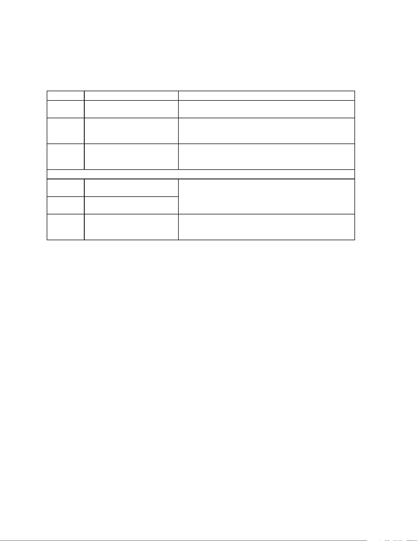
14c)(3) After the water tank has drained, replace the overow pipe and rubber cap and
sleeve in their correct positions. NOTICE! Make sure the O-ring is attached to the
bottom of the overow pipe and be careful not to cross thread the overow
pipe.
14c)(4) Replace cube guide A in its correct position. Continue to step 15 below.
NOTICE! The rear portion of cube guide A must be placed back to the outside
of the evaporator plastic bracket to allow proper positioning of cube guide A.
15) Replace the front insulation panel in its correct position.
16) Clean the dispenser unit/ice storage bin liner using a neutral cleaner. Rinse thoroughly
after cleaning.
17) Move the control switch to the "ON" position. Replace all panels in their correct
positions.
18) Turn on the power supply to start the automatic icemaking process.
19) Return to "II.G.2. Post-Startup" and complete nal checklist.
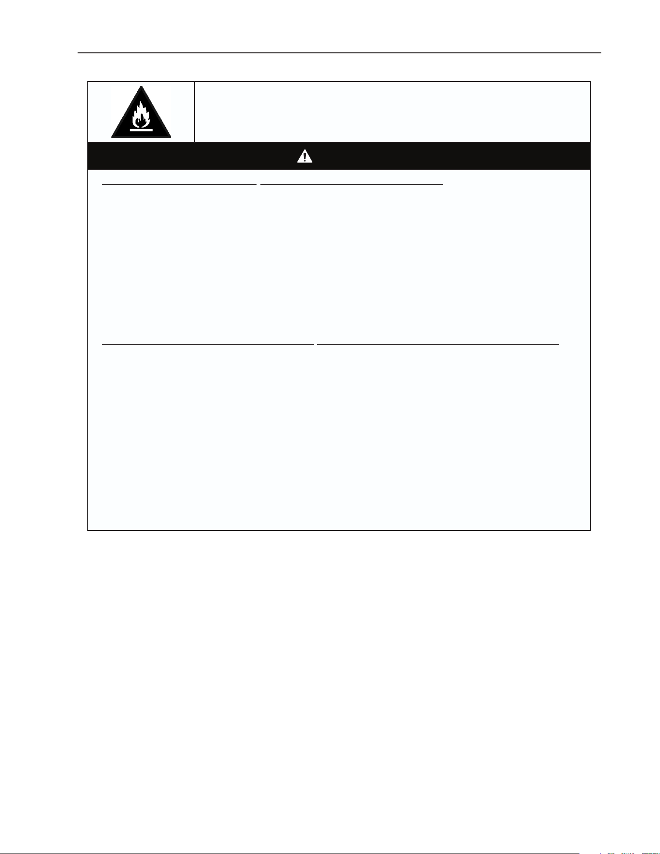
Fig. 17
Rubber Cap
Overow Pipe
Sleeve
O-Ring
Cube Guide
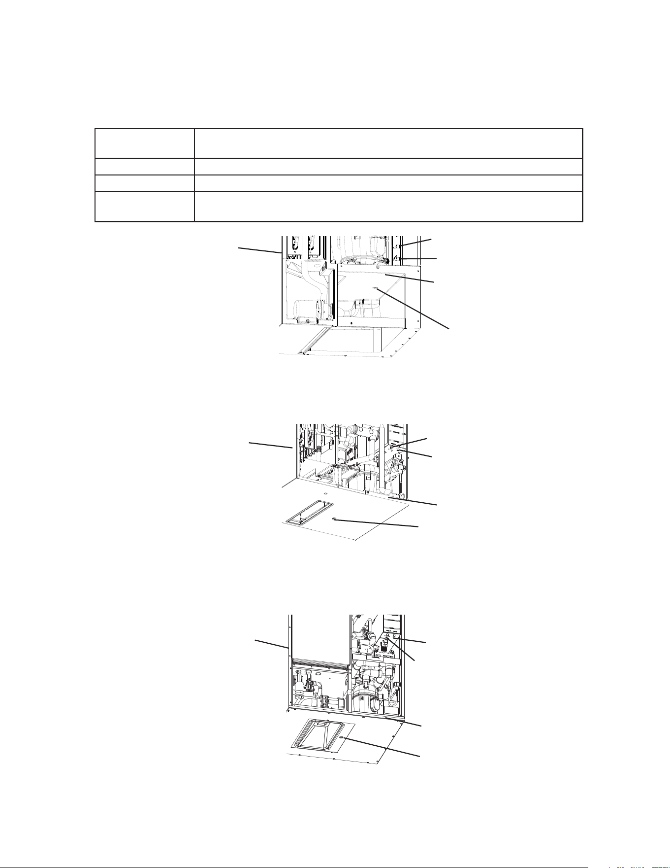
14c)(2) Remove the rubber cap and sleeve covering the overow pipe. See Fig. 17.
Unscrew the overow pipe.
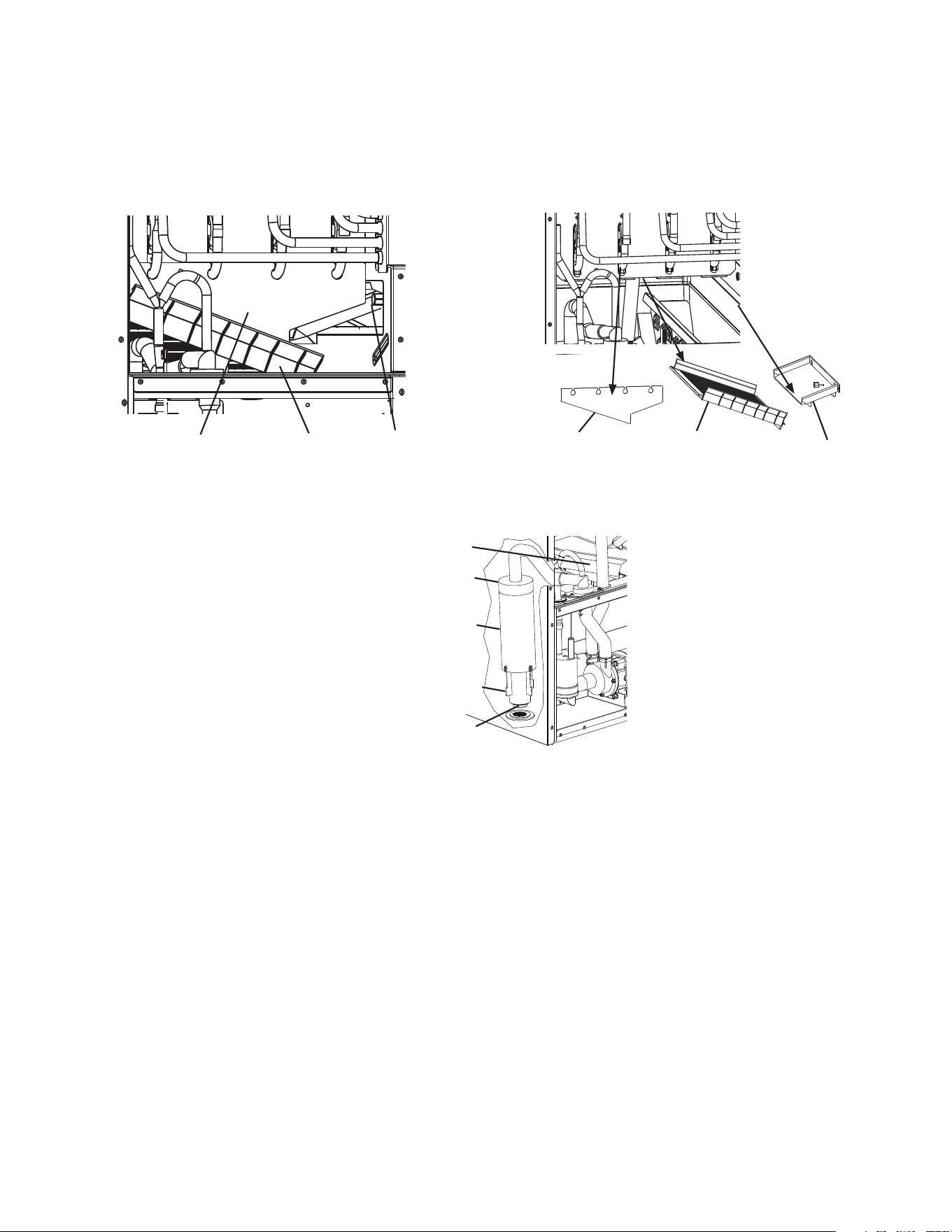
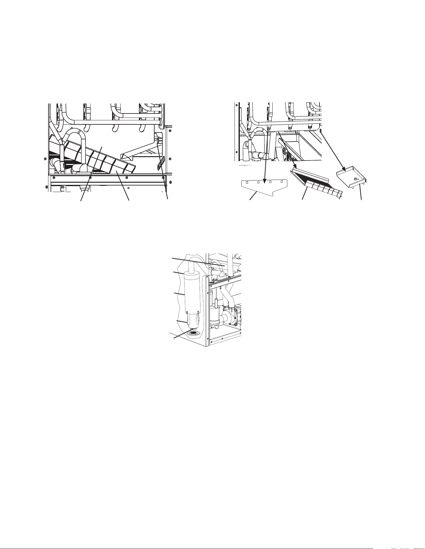
14c)(1) For KM-930MAK2 and KM-1130MAK2 - Remove the splash guard and cube guide
B. See Fig. 16.
Next, slide cube guide A to the right and pull forward to remove cube guide A.
NOTICE! The rear portion of cube guide A is placed outside and underneath
the rear evaporator bracket. Lift the front of cube guide A and push down and
pull cube guide A to slide it out from under the rear evaporator bracket.
Splash Guard Cube Guide A Cube Guide B Splash Guard Cube Guide A
Cube Guide B
Fig. 16
34
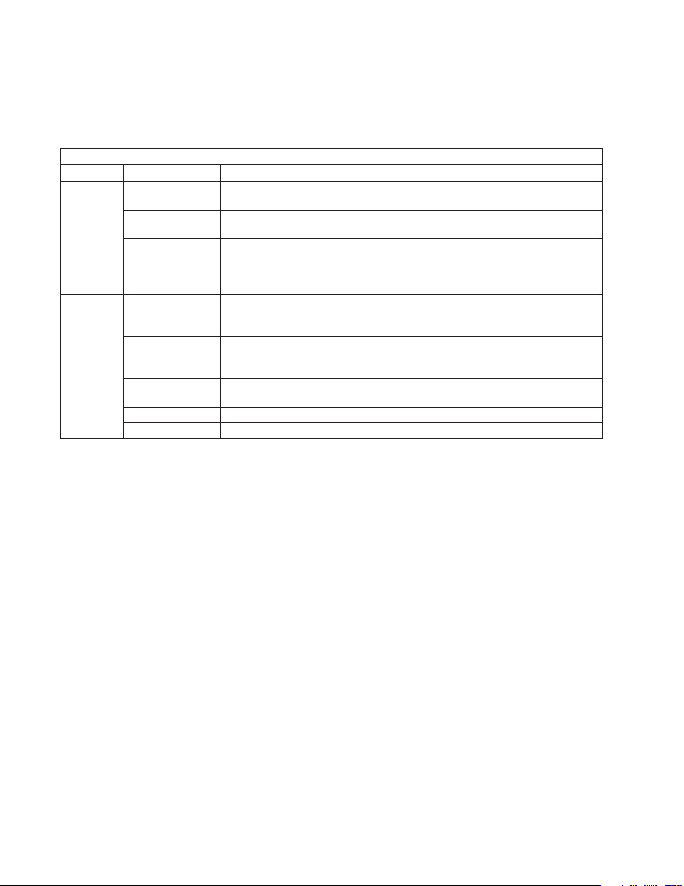
C. Alarm Safeties
Should an alarm occur, follow the instructions in the table below to address the alarm.
If an alarm continues to occur, contact an authorized service agent.
In case of alarm, the built-in safeties shut down the appliance and an audible alarm
sounds as listed below.
Type Alarm Notes and Reset Options
1
Beep
High Evaporator Temp.
(temperature > 127°F) (53°C)
Check for harvest problem (stuck HGV or relay),
hot water entering unit, stuck HM, or shorted thermistor.
2
Beep
Harvest Backup Timer
(harvest > 20 min. for two
cycles in a row)
Check thermistor (open), HGV not opening, TXV or LLV
leaking by, low charge, inefficient Comp, or WRV leaking
by.
3
Beep
Freeze Timer
(freeze > freeze timer setting
for two cycles in a row)
Check FS stuck closed (up), WV leaking by, HGV leaking
by, PM not pumping, TXV defective, LLV not opening, low
charge, HMnot bypassing, or inefficient Comp.
To reset above safeties, press "ALARM RESET" button with power supply on.
6 Low Voltage
(92Vac±5% or less)
Red "POWER" LED turns off if voltage protection
operates.
Control voltage safeties automatically reset when voltage
is corrected.
7 High Voltage
(147Vac±5% or more)
"Power"
LED Blink
Only
Freeze Up Detection Cycle Freeze up detection cycle initiated. "POWER" LED blinks
until 6 FS activated freeze cycles completed or control
board manually reset. See service manual for details.
Legend: Comp–compressor; CV–cleaning valve; DV–drain valve; FM–fan motor;
FS–oat switch; HGV–hot gas valve; L LV–liquid line valve; PM–pump motor;
TXV–thermostatic expansion valve; WRV–water regulating valve; WV–inlet water
valve
35
IV. Maintenance
The appliance must be maintained in accordance with the instruction manual and
labels provided with the appliance. Consult with your local Hoshizaki Certied Service
Representative about maintenance service. To obtain the name and phone number of
your local Hoshizaki Certied Service Representative, visit www.hoshizakiamerica.com.
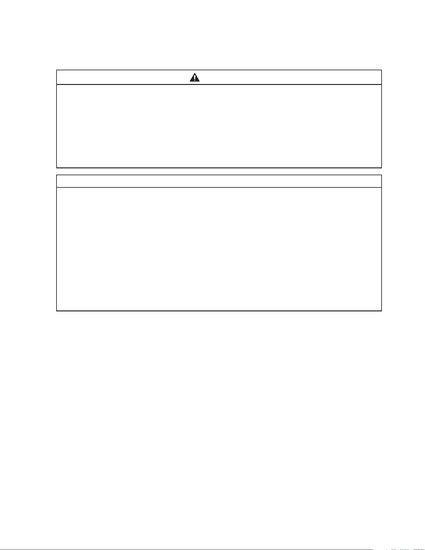
WARNING
• Items listed under "IV.A. User Maintenance Schedule" may be performed by the
user; otherwise, only qualied service technicians should service the appliance.
• Failure to install, operate, and maintain the equipment in accordance with this
manual will adversely affect safety, performance, component life, and warranty
coverage.
• To reduce the risk of electric shock, do not touch the control switch or mode switch
with damp hands.
• Before Performing Maintenance/Service: Move the control switch to the "OFF"
position and turn off the power supply. Lockout/Tagout to prevent the power supply
from being turned back on inadvertently. Control switch in "OFF" position does not
de-energize all loads.
• CHOKING HAZARD: Ensure all components, fasteners, and thumbscrews are
securely in place after any maintenance is done to the appliance. Make sure that
none have fallen into the dispenser unit/ice storage bin.
• After service, make sure that there are no wires pinched between the panels and
appliance. Make sure you do not damage or pinch the water supply line or drain line.
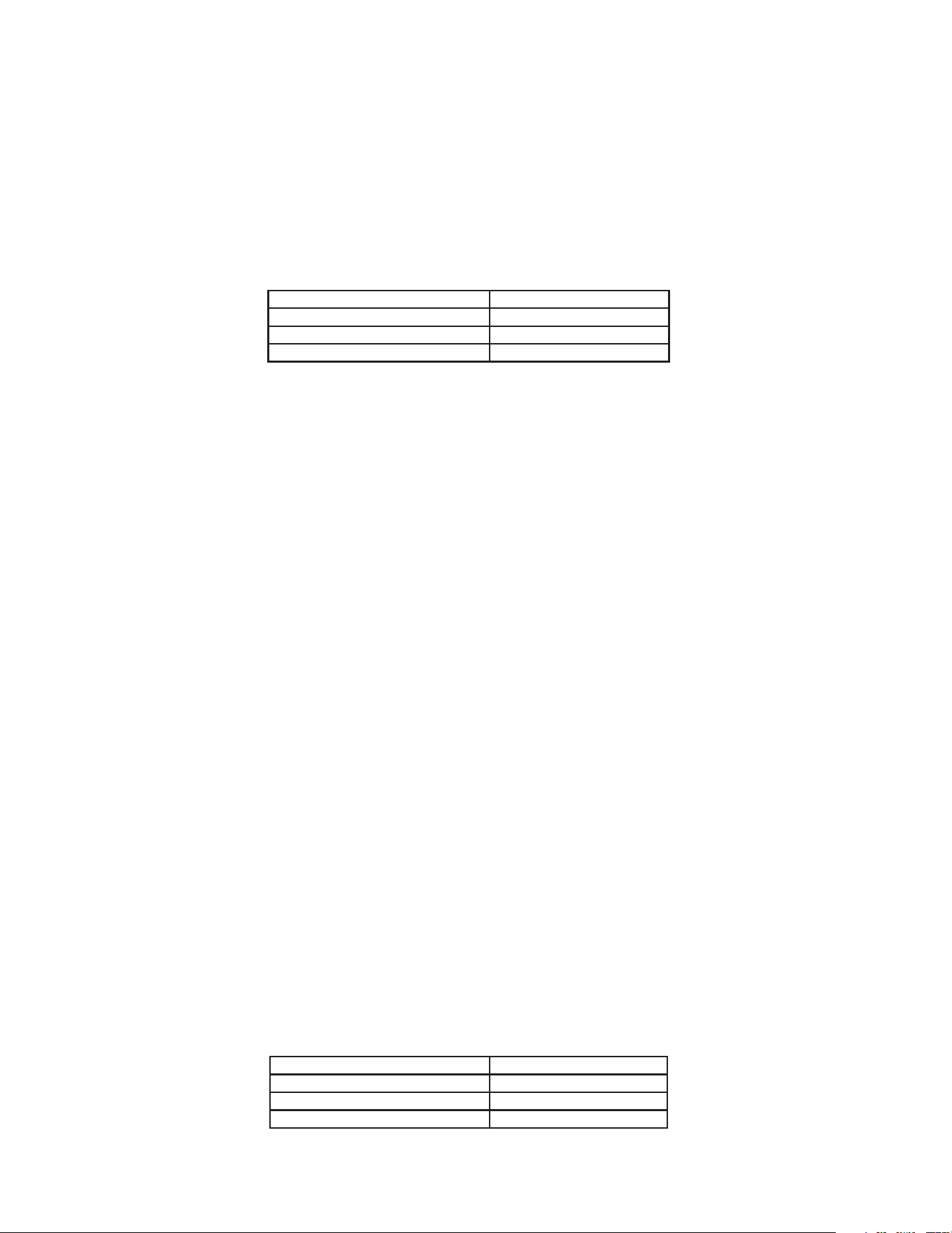
A. User Maintenance Schedule
The user maintenance schedule below is a guideline. More frequent maintenance may
be required depending on water quality, the appliance's environment, and local sanitation
regulations.
Maintenance Schedule
Frequency Area Task
Daily Scoop Clean the ice scoop using a neutral cleaner. Rinse thoroughly after
cleaning.
Bi-Weekly Air Filters Inspect. Wash with warm water and neutral cleaner if dirty.
Monthly Appliance Exterior Wipe down with a clean, soft cloth. Use a damp cloth containing a neutral
cleaner to wipe off oil or dirt build up. Clean any chlorine staining (rust
colored spots) using a non-abrasive cleanser.
36
B. Service Maintenance Schedule
The service maintenance schedule below is a guideline; service maintenance items are
to be performed by qualied service technicians only. More frequent maintenance may
be required depending on water quality, the appliance's environment, and local sanitation
regulations.
Maintenance Schedule
Frequency Area Task
Monthly External Water
Filters
Check for proper pressure and change if necessary.
Bin Control Lens Wipe down the bin control lens, (located on the bottom of the icemaker) with
a neutral cleaner. Rinse thoroughly after cleaning.
Underside of
Icemaker and Top
Kits; Bin Door and
Snout
Wipe down with a clean, soft cloth. Use a damp cloth containing a neutral
cleaner to wipe off oil or dirt build up. Clean any chlorine staining (rust
colored spots) using a non-abrasive cleanser.
Yearly Icemaker and
Dispenser Unit/Ice
Storage Bin
Clean and sanitize per the cleaning and sanitizing instructions provided in
this manual.
Inlet Water Valve,
Cleaning Valve,
and Drain Valve
Close the water supply line shut-off valve and drain the water system.
Clean the inlet water valve and cleaning water valve screens and clean and
inspect the drain valve.
Condenser Inspect. Clean if necessary by using a brush or vacuum cleaner. More
frequent cleaning may be required depending on location.
Water Hoses Inspect the water hoses and clean/replace if necessary.
Appliance Inspect for oil spots, loose components, fasteners, and wires.
37
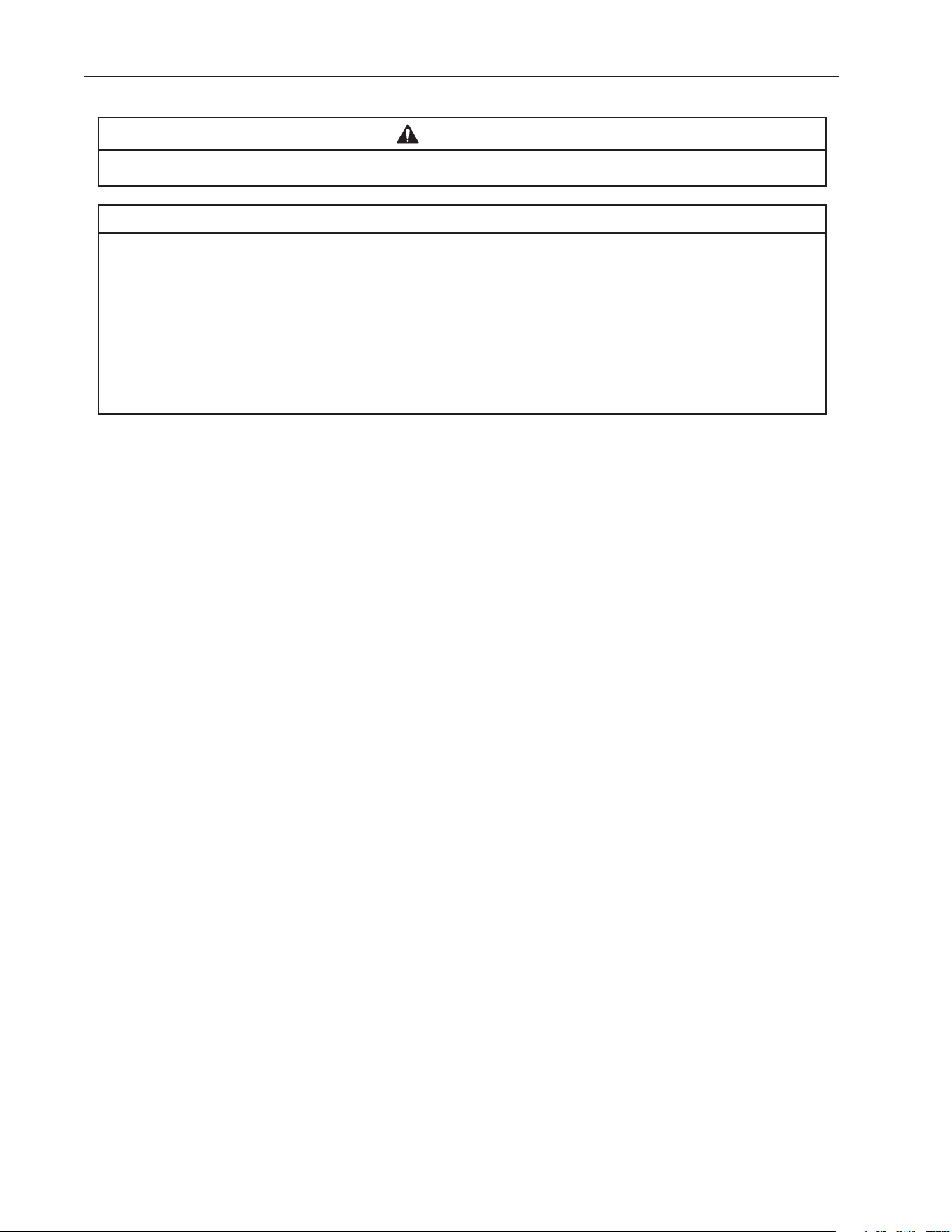
C. Cleaning and Sanitizing Instructions
The icemaker must be cleaned and sanitized at least once a year. More frequent
cleaning and sanitizing may be required in some water conditions.
WARNING
• To prevent injury to individuals and damage to the icemaker, do not use ammonia
type cleaners.
• Carefully follow any instructions provided with the bottles of cleaning and
sanitizing solution.
• Always wear liquid-proof gloves and goggles to prevent the cleaning and sanitizing
solutions from coming into contact with skin or eyes.
• Do not leave the icemaker unattended when panels are off.
NOTICE
• To prevent damage to the water pump, do not leave the control switch in the
"PUMP" position for extended periods when the water tank is empty.
• Terminating a cleaning/sanitizing cycle early:
a) Terminating a cleaning cycle at step 4 or earlier in "Cleaning" below, returns
the icemaker to the normal icemaking mode. The control board "CLEAN" LED
turns off.
b) Terminating a cleaning cycle at step 5 or later in "Cleaning" below, sends the
icemaker into a 3-rinse cycle (approx. 18 min.). The control board "CLEAN"
LED remains on throughout the 3-rinse cycles. After the 3rd rinse cycle,
icemaker goes into the normal icemaking mode and the control board "CLEAN"
LED turns off.
Preparation
1) Remove the front panel, then move the control switch to the "OFF" position. Make sure
the mode switch is in the "ICE" position. After 3 minutes, move the control switch to the
"ON" position and replace the front panel.
2) Allow the appliance to run until the compressor energizes. Once the compressor
energizes, allow the appliance to run for an additional 3 minutes, then remove the front
panel and control box cover. Move the control switch to the "OFF" position.
3) Remove all ice from the dispenser unit/ice storage bin. WARNING! If on a dispenser
unit, turn off the dispenser unit power supply after dispensing the ice.
38
Cleaning
4) Move the mode switch to the "CLEAN" position, then move the control switch to the
"ON" position (1 short beep occurs, then 3 seconds later 1 long beep occurs). Replace
the front panel. The water tank drains and then lls.
5) When the control board starts beeping (2 beep sequence), remove the front panel.
Move the control switch to the "OFF" position.
6) Remove the front insulation panel, then pour Hoshizaki "Scale Away" into the water
tank. See the table below for amount. Replace the front insulation panel.
Model Scale Away
KM-322_522_622MAK 13 . oz. (384 ml)(26 tbs)
KM-330_530_730MAK 17 . oz. (503 ml)(34 tbs)
KM-930MAK2, KM-1130MAK2 20 . oz. (591 ml)(40 tbs)
7) Move the control switch to the "ON" position (1 short beep occurs, then 3 seconds later
1long beep occurs). Replace the front panel. To avoid excessive foaming in the water
tank, there is a 1minute delay before circulation begins. After approximately 30 minutes
of circulation, the icemaker performs 3 rinse cycles.
8) When the control board starts beeping (5 beep sequence), remove the front panel.
Move the control switch to the "OFF" position.
9) In bad or severe water conditions, turn off the power supply, then remove, clean
(cleaning solution = 5 oz. Hoshizaki "Scale Away" per gallon of warm water), rinse, and
replace the cube guide, oat switch, water supply tubes, spray tubes, and spray guides;
turn on the power supply when complete. Otherwise, continue to step 10.
10) Wipe down the bin control lens, (located on the bottom of the icemaker) with a neutral
cleaner. Rinse thoroughly after cleaning. Note: If the bottom of the icemaker is not
accessible in your application, remove the top and right side panels, then remove the
thumbscrew securing the bin control housing and remove the bin control housing from
the base. After cleaning and rinsing the bin control lens, replace the bin control housing
in its correct position and secure it with the thumbscrew. Next, replace the right side and
top panels in their correct positions.
Sanitizing
11) Conrm the mode switch is in the "CLEAN" position, then move the control switch to the
"ON" position (1 short beep occurs, then 3 seconds later 1 long beep occurs). Replace
the front panel. The water tank drains and then lls.
12) When the control board starts beeping (2 beep sequence), remove the front panel.
Move the control switch to the "OFF" position.
13) Remove the front insulation panel, then pour 7.5% sodium hypochlorite solution
(chlorine bleach) into the water tank. See the table below for amount. Replace the
front insulation panel. IMPORTANT! Use regular bleach with no additives. Using a
bleach with additives causes excessive foaming during sanitizing, reducing the
effectiveness of sanitizing.
Model Scale Away
KM-322_522_622MAK 0.8 . oz. (24 ml)(1.6 tbs)
KM-330_530_730MAK 1.0 . oz. (31 ml)(2 tbs)
KM-930MAK2, KM-1130MAK2 1.3 . oz. (38 ml)(2.5 tbs)

39
14) Move the control switch to the "ON" position (1 short beep occurs, then 3 seconds later
1long beep occurs). Replace the front panel. To avoid excessive foaming in the water
tank, there is a 1minute delay before circulation begins. After approximately 30 minutes
of circulation, the icemaker performs 3rinse cycles.
15) When the control board starts beeping (5 beep sequence), remove the front panel.
Move the control switch to the "OFF" position.
16) Clean the dispenser unit/ice storage bin liner using a neutral cleaner. Rinse thoroughly
after cleaning.
17) Move the mode switch to the "ICE" position, then move the control switch to the "ON"
position. Note: If on a dispenser unit, turn on the dispenser unit power supply.
18) Replace all panels and covers in their correct positions.
40
V. Preparing the Appliance for Periods of Non-Use
WARNING
Only qualied service technicians should service this appliance.
NOTICE
• During extended periods of non-use, extended absences, or in sub-freezing
temperatures, follow the instructions below to reduce the risk of costly water
damage.
• When the appliance is not used for two or three days under normal conditions, it
is sufficient to move the control switch to the "OFF" position.
• To prevent damage to the water pump, do not leave the control switch in the
"PUMP" position for extended periods when the water tank is empty.
When the appliance is not used for two or three days under normal conditions, it is
sufficient to move the control switch to the "OFF" position. When storing the appliance for
an extended time or in sub-freezing temperatures, follow the instructions below.
1. Remove the water from the icemaker water supply line:
1) Remove the front panel. Move the control switch to the "OFF" position, then turn off the
power supply.
2) Close the icemaker water supply line shut-off valve, then open the icemaker water
supply line drain valve.
3) Allow the line to drain by gravity.
4) Attach a compressed air or carbon dioxide supply to the icemaker water supply line
drain valve.
5) Move the control switch to the "ICE" position.
6) Replace the front panel in its correct position, then turn on the power supply.
7) Blow the icemaker water supply line out using the compressed air or carbon dioxide
supply.
8) Close the icemaker water supply line drain valve.
41
Fig. 17
2. Drain the water tank:
1) Remove the front panel. Move the control switch to the "OFF" position, then turn off the
power supply.
2a)(1) For KM-322_522_622MAK - Remove the front insulation panel, then disconnect the
water tank pump tubing located behind the base cover. See Fig. 17. Allow the water
tank to drain.
Control Switch
Mode Switch
Water Tank
Base Cover
Disconnect This End
of Pump Tubing to
Drain Water Tank
Icemaker
2a)(2) After the water tank has drained, replace the water tank pump tubing and base cover
back in their correct positions. Continue to step 3 below.
2b)(1) For KM-330_530_730MAK - Remove the front insulation panel, then remove the
water tank drain plug located in the bottom of the water tank. See Fig. 18. Allow the
water tank to drain.
Fig. 18
Drain Plug
2b)(2) After the water tank has drained, replace the drain plug back in its correct position.
Continue to step 3 below.
42
2c)(2) Remove the rubber cap and sleeve covering the overow pipe. See Fig. 21.
Unscrew the overow pipe.
Fig. 21
Rubber Cap
Overow Pipe
Sleeve
O-Ring
Cube Guide
2c)(3) After the water tank has drained, reconnect the overow pipe. Replace the rubber cap
and sleeve in their correct positions. Continue to step 3 below. NOTICE! Make sure
the O-ring is attached to the bottom of the overow pipe and be careful not to
cross thread the overow pipe.
2c)(4) Replace cube guide A in its correct position. NOTICE! The rear portion of cube
guide A must be placed back to the outside of the evaporator plastic bracket to
allow proper positioning of cube guide A.
3) Replace the front insulation panel and front panel in their correct positions.
4) Remove all ice from the dispenser unit/ice storage bin. Clean the dispenser unit/ice
storage bin liner using a neutral cleaner. Rinse thoroughly after cleaning.
Splash Guard Cube Guide A Cube Guide B Splash Guard Cube Guide A Cube Guide B
Fig. 20
2c)(1) For KM-930MAK2 and KM-1130MAK2 - Remove the splash guard and cube guide
B. See Fig. 20.
Next, slide cube guide A to the right and pull forward to remove cube guide A.
NOTICE! The rear portion of cube guide A is placed outside and underneath the
rear evaporator bracket. Lift the front of cube guide A and push down and pull
cube guide A to slide it out from under the rear evaporator bracket.
43
VI. Decommissioning and Disposal
R-290 Class A3 Flammable Refrigerant Used*
DANGER
Risk of Fire or Explosion. Flammable Refrigerant Used.*
• Only qualied service technicians should install and service the appliance.
• Follow handling instructions carefully in compliance with national regulations.
• Dispose of properly in accordance with federal or local regulations.
• Do not puncture refrigerant tubing. Risk of re or explosion due to puncture of
refrigerant tubing; follow handling instructions carefully.
• Be sure to follow the full Decommissioning and Disposal information located in the
Service Manual for this model. The Service Manual is available at:
www.hoshizakiamerica.com.
Risque D'Incendie ou D'Explosion. Fluide Frigorigène Inammable Utilisé.*
• Seuls des techniciens de service qualiés doivent installer et entretenir l'appareil.
• Suivre attentivement les instructions de manutention conformément aux réglements
nationaux.
• Mettre au rebut conformément aux conformément aux réglements fédéraux ou
locaux.
• Ne pas perforer la conduite de uide frigorigène. Risque d'incendie ou d'explosion
en cas de perforation d'une canalisation de uide frigorigène; suivez attentivement
les instructions de manutention.
• Veiller à respecter l'ensemble des informations relatives à la mise hors service et
à la mise au rebut gurant dans le manuel d'entretien de ce modèle. Le manuel
d'entretien est disponible à l'adresse suivante: www.hoshizakiamerica.com.
*This statement applies to models utilizing R-290 refrigerant. See the nameplate or the
Electrical and Refrigerant Data section of this manual for the refrigerant type in your
model.
*Cette déclaration s’applique aux modèles utilisant le réfrigérant R-290. Consultez la
plaque signalétique ou la section Données électriques et de réfrigérant de ce manuel
pour connaître le type de réfrigérant de votre modèle.

44
618 Hwy. 74 South, Peachtree City, GA 30269 USA (P) 770.487.2331 (F) 770.487.3360 hoshizakiamerica.com 1A8309-012

