OPERATING AND INSTALLATION INSTRUCTIONS
FOR WHISPAIR RANGEHOODS
UTILISING ON BOARD FAN MOTOR UNITS
CONGRATULATIONS
Congratulations and thank you for choosing a
Whispair rangehood.
We recommend that you keep this instruction
booklet for future reference and pass it on to any
future owners.
AFTER UNPACKING THE RANGEHOOD
PLEASE REVIEW YOUR NEW ITEM TO ENSURE
THAT IT HASN’T BEEN DAMAGED IN TRANSIT
OR IS MISSING ANY COMPONENTS. FAILURE
TO REPORT ANY ISSUE WITHIN 72 HOURS OF
RECEIPT OF YOUR ITEM MAY RESULT IN
ADDITIONAL CHARGES.
TO AVOID THE RISK OF INJURY OR
DAMAGE TO THE PRODUCT IT IS
ESSENTIAL TO READ THESE
INSTRUCTIONS PRIOR TO
INSTALLATION AND USE
IMPORTANT INFORMATION
Information on disposal for users
Most of the packing materials are recyclable. Please
dispose of those materials through your local
recycling depot or by placing them in a appropriate
collection bin.
If you wish to discard this product, please contact your
local authorities and ask for the correct method of
disposal.
ENVIRONMENTAL TIP
1

PRODUCT DESCRIPTION & CARTON CONTENTS
CARTON 1 - RANGEHOOD UNIT WITH INTEGRATED FAN MODEL
This Operating & Installation Instruction covers the following Whispair On Board (Power & Ultra) Motor rangehood
models:
Undermount //
Standard (280mm) Depth // X3M06S5.OP(/T /B), X3M06S6.OU(/T /B), X3M08S5.OP(/T /B), X3M08S6.OU(/T /B),
X3M09S5.OP(/T /B), X3M09S6.OU(/T /B), X3M12S5.OP(/T /B), X3M12S6.OU(/T /B), X3M16S6.2OU(/T /B)
Super (380mm) Depth // X3MD09S5.OP(/T /B), X3MD09S6.OU(/T /B), X3MD12S5.OP(/T /B), X3MD12S6.OU(/T /B),
X3MD16S6.2OU(/T /B)
Mega (480mm) Depth // X3MM09S5.OP(/T /B), X3MM09S6.OU(/T /B), X3MM12S6.OU(/T /B), X3MM12S6.2OU(/T /B),
X3MM16S6.2OU(/T /B), X3MM20S6.2OU(/T /B), X3T12S6.2OU(/T /B), X3T16S6.2OU(/T /B)
Project (280mm) Depth // X3UM06S5.OP/T, X3UM09S5.OP/T, X3UM12S5.OP/T
Wall Hung Canopies //
X5L09S5.OP(/T /B), X5L09S6.OU(/T /B), X5S06S5.OP(/T /B), X5S06S6.OU(/T /B), X5S09S5.OP(/T /B),
X5S09S6.OU(/T /B), X5R09S5.OP(/T /B), X5R09S6.OU(/T /B), X5R09W5.OP(/T /B), X5R09W6.OU(/T /B),
X5V09S5.OP(/T /B), X5V09S6.OU(/T /B), X5V12S6.OU(/T /B), X5Z09S5.OP/T, X5Z09S6.OU/T, X5Z12S5.OP/T,
X5Z12S6.OU/T, X5A12S6.2OU/T, X5A15S6.2OU/T, X5A18S6.2OU/T
Island Hung Canopies //
X7S09S5.OP/T, X7S09S6.OU/T, X7R09S5.OP/T, X7R09S6.OU/T, X7R09W5.OP/T, X7R09W6.OU/T, X7V09S5.OP/T,
X7V09S6.OU/T, X7V12S6.OU/T, X7P04S5.OP/T, X7P04S6.OU/T, X7P05S5.OP/T, X7P05S6.OU/T, X7Z09S5.OP/T,
X7Z09S6.OU/T, X7Z12S5.OP/T, X7Z12S6.OU/T, X7ZD09S6.OU/T, X7ZD12S6.2OU/T, X7H09S5.OP/T,
X7H09S6.OU/T, X7H12S5.OP/T, X7H12S6.OU/T
Ceiling Cassettes //
X9C12S5.OP(/T /B), X9C12S6.OU(/T /B)
Items included in the carton:
1. Main hood housing (including switch control, led lighting and fan motor) (1x)
2. Bafe lters (Quantity varies depending on model)
3. Grease trap (1x)
4. Stainless steel chimney (2x Wall Hung models, 1x Island Hung models)
5. Chimney bracket (1x Wall & Island Hung Models)
6. Wall mounting bracket (1x Wall Hung Models)
7. Fixing screws
8. Operating & installation guide
9. Transition Duct - rectangle to round outlet (Top ducted Ultra models only)
10. Rear Duct Kit (Back ducted models only)
2
CONDITIONS OF USE AND MAINTENANCE
This rangehood is a domestic appliance which has been manufactured and tested to comply with Australian and New Zealand
Standard AS/NZS 60335.2.31 and is designed to work under Australian and New Zealand conditions. The hoods are designed
to remove bi-products of cooking – heat, steam, grease and odour.
This appliance is intended for domestic application only. Any other usage is at the owner’s risk and could be dangerous. The
manufacturer cannot be held liable for damage resulting from incorrect or improper use or operation. This unit is approved for
electrical safety (Please refer RCM E4759).
WHISPAIR reserves the right to change the specication without notice.
All WHISPAIR performance gures are based upon standards developed by the Haus Group, which either comply or are in excess
of the government regulated standards.
3
SAFETY
WARNING: The installation of WHISPAIR rangehoods must comply with the information in this guide. Failure to install the
rangehood in accordance with these installation instructions may result in electrical hazards, injury, damage to your appliance
and loss of warranty. Specically, failure by the installer to install the screws or xing devices in accordance with these
installation instructions may result in electrical hazards. Please install the appliance as detailed in these instructions.
This appliance is not intended for use by persons (including children) with reduced physical, sensory or mental capabilities, or
lack of experience and knowledge, unless they have been given supervision or instruction concerning use of the appliance by a
person responsible for their safety.
Children should be supervised to ensure that they do not play with the appliance.
There shall be adequate ventilation of the room when the range hood is used at the same time as appliances burning gas or other
fuels.
The air must not be discharged into a ue that is used for exhausting fumes from appliances burning gas or other fuels (not
applicable to appliances that only discharge the air back into the room).
Exhaust from a kitchen range hood must discharge directly or via a shaft or duct to outdoor air as per the local state and council
regulations.
There is a re risk if cleaning is not carried out in accordance with the instructions.
Bafe lters and grease trap must be regularly cleaned (every 4 weeks) to reduce the risk of re.
CAUTION: Accessible parts may become hot when used with cooking appliances. Stainless steel bafe lter edges can be sharp
when handling and cleaning.
Ensure the rangehood is switched off and power source cable unplugged before carrying out maintenance, to avoid any possibility
of electric shock.
Always use non-ammable materials to minimize the risk of re.
Do not ambé under the range hood.
Always cover lit gas burners with pots or pans when cooker hood is in use.
If the supply cord is damaged, it must be replaced by the manufacturer, its service agent or similarly qualied persons in order to
avoid a hazard.
Please ensure the hood is securely xed to the support as detailed in this guide. The method of xing stated is not to depend on
the use of adhesives as they are not a means of reliable xing.
The height of the underside of the hood body must be a minimum of 600mm above an electric cooktop, for a gas cooktop a
minimum of 650mm measured from the supporting surface of the trivet for the cooking vessels (excluding the wok support) to the
underside of the hood body and a minimum height of 1200mm above BBQ cookers. If the instructions of the hob specify a greater
distance than the minimum detailed, this shall be the minimum height for installation.

DUCTING AND EXTRACTION LEVELS
WHISPAIR ducting (not supplied) is designed to ensure optimum performance for your rangehood. Please follow the installation
instructions carefully.
Every WHISPAIR rangehood must be ducted to the outside environment by the use of non-ammable ducting. The rangehood
must not be ducted into a wall cavity or a ceiling space where a build-up of grease can occur and become a potential re risk.
Ensure the external outlet on the KLEENAIR unit is not covered and the air ow is not restricted in any way as this may result in
reduced performance.
The duct must at all times have a cross sectional surface area equivalent to the hood outlet. The rectangular hood outlet (Ultra
motor models) has an approximate area of 21,992mm2 and the 150mm diameter round outlet (Power motor models) has an area
of 17,696mm2. Do not reduce the duct size at any time and avoid sharp bends. If the duct run is longer than six (6) metres, it
may be necessary to enlarge the duct size to ensure optimum performance. The manufacturer does not guarantee performance
when the duct length is greater than six (6) metres.
Ensure that all ducting is correctly tted and sealed with pipe clips, duct tape or silicone to ensure that fumes do not escape prior
to reaching the KLEENAIR fan motor unit.
The WHISPAIR extraction calculations are based upon a 50pa change of head of pressure loss and are used to factor the variance
of air ow resistance through the ducting. 50pa is equivalent to approximately four (4) metres (the recommended length) of exi
ducting with one gentle bend, which is above and beyond the industry standard of one straight metre of ducting. The KLEENAIR
ULTRA offers a powerful 1680 cubic metres per hour (466 litres per second) and the KLEENAIR POWER offers a powerful 1020
cubic metres per hour (283 litres per second) of air movement.
4
SERVICING
The installation and tting of the rangehood should be done in such a way that will allow the unit to be removed if service is
required. Additional costs incurred in the removal, such as damage to walls, are not covered under warranty.
It is expected that the stainless steel is cleaned with a quality non-abrasive stainless steel cleaner. The bafe lters and grease
trap are removable and dishwasher safe. It is recommended that these items be cleaned regularly.
The KLEENAIR unit should be checked regularly to ensure that nothing is obstructing the air ow from the housing.
DUCTING OPTIONS
WHISPAIR undermount or wall hung canopy hoods utilising on-board motor systems can be top or rear ducted.
Top Ducting:
Top Ducted with the Ultra motor options come with a rectangular to circle transition piece (supplied) which enables the 200mm
diameter duct to be connected.
Back Ducting:
Back Ducted options come with a duct kit (supplied) which includes a duct piece and wall vent.
5
RECTANGULAR
TOP OUTLET
TRANSITION DUCT
Model X1DK.TRANS
200mm OUTLET
RECTANGULAR
BACK OUTLET
WALL VENT KIT
Model X1DK.WVENT
PART 1: HOOD INSTALLATION GUIDE
Undermount Hood with Integrated Fan Motor
Models Included: X3M06S5.OP(/T/B), X3M06S6.OU(/T/B), X3M08S5.OP(/T/B), X3M08S6.OU(/T/B), X3M09S5.OP(/T/B),
X3M09S6.OU(/T/B), X3M12S5.OP(/T/B), X3M12S6.OU(/T/B), X3M16S6.2OU(/T/B), X3MD09S5.OP(/T/B), X3MD09S6.OU(/T/B),
X3MD12S5.OP(/T/B), X3MD12S6.OU(/T/B), X3MD16S6.2OU(/T/B), X3MM09S5.OP(/T/B), X3MM09S6.OU(/T/B),
X3MM12S6.OU(/T/B), X3MM12S6.2OU(/T/B), X3MM16S6.2OU(/T/B), X3MM20S6.2OU(/T/B), X3T12S6.2OU(/T/B),
X3T16S6.2OU(/T/B), X3UM06S5.OP/T, X3UM09S5.OP/T, X3UM12S5.OP/T
6
STEP 1:
To install into your overhead cupboard;
Top Ducting - several holes may need to be cut into shelves to enable the
ducting to exit the cabinetry.
Back Ducting - cut a rectangular hole through the wall taking into account the
rear duct outlet of the hood.
NOTE:
The height of the underside of the hood body must be a minimum of 600mm
above an electric cooktop, for a gas cooktop a minimum of 650mm measured
from the supporting surface of the trivet for the cooking vessels (excluding the
wok support) to the underside of the hood body and a maximum height of
1000mm.
Building codes that stipulate a minimum dimension may vary from state to state,
please check with your local council prior to installation.
Ensure the hood is mounted as close to the centre of the cooking surface as
possible.
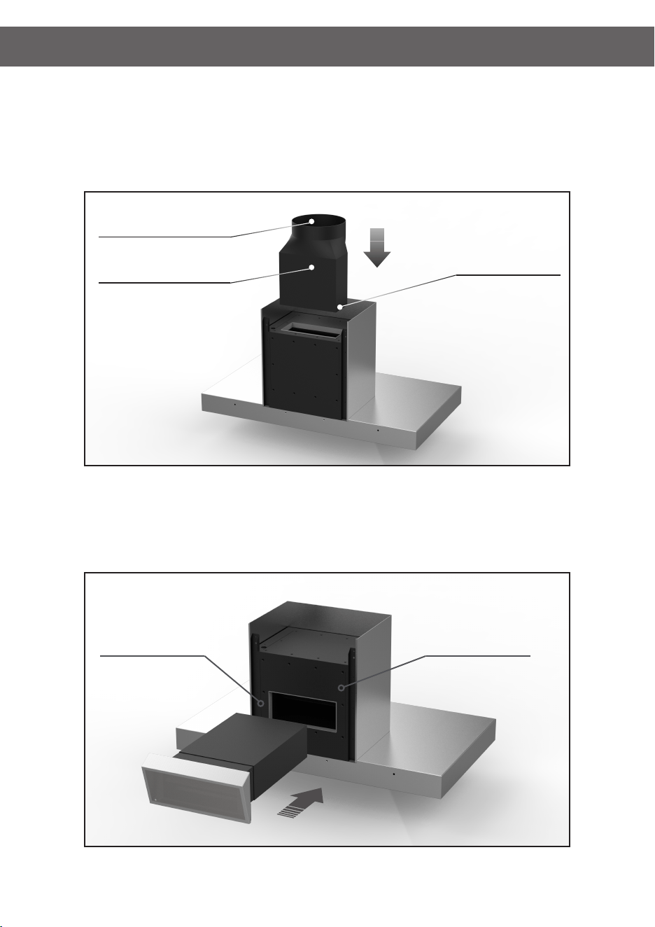
STEP 2:
Remove the grease trap and three (3) screw xings from within the Main Chassis
of the rangehood located along the rear chassis wall (located above the grease
trap), along with two (2) screws on the left side and two (2) screws on the right
side. Once the screws are removed, the Fascia will separate away from the Main
Chassis.
STEP 3:
Fixing Holes are located on the returns of the main chassis. These Fixing Holes
are used to secure the main chassis to the cabinetry.
STEP 4:
Place the Main Chassis in the cabinet ensuring that the hood is level and the
controls and display will be visible when standing in front of the unit.
WARNING
FAILURE BY THE INSTALLER TO INSTALL THE SCREWS OR FIXING DEVICES IN ACCORDANCE WITH THESE INSTALLATION
INSTRUCTIONS MAY RESULT IN ELECTRICAL HAZARDS. DIMENSIONS ARE ACCURATE AT THE TIME OF PRINTING, HAUS
GROUP RESERVES THE RIGHT TO CHANGE SPECIFICATIONS WITHOUT NOTICE. FOR BUILDING PURPOSES THE UNIT
SHOULD BE PROVIDED TO THE CABINET MAKER / BUILDER / KITCHEN DESIGNER FOR EXACT MEASUREMENTS.
Outlet
Bafe Filters Grease Trap
Main Chassis
Fascia
Step 2: Remove Fascia from Chassis
Fixing Holes
Step 3: Locate the Fixing Holes of the Main Chassis
PART 1: HOOD INSTALLATION GUIDE
7
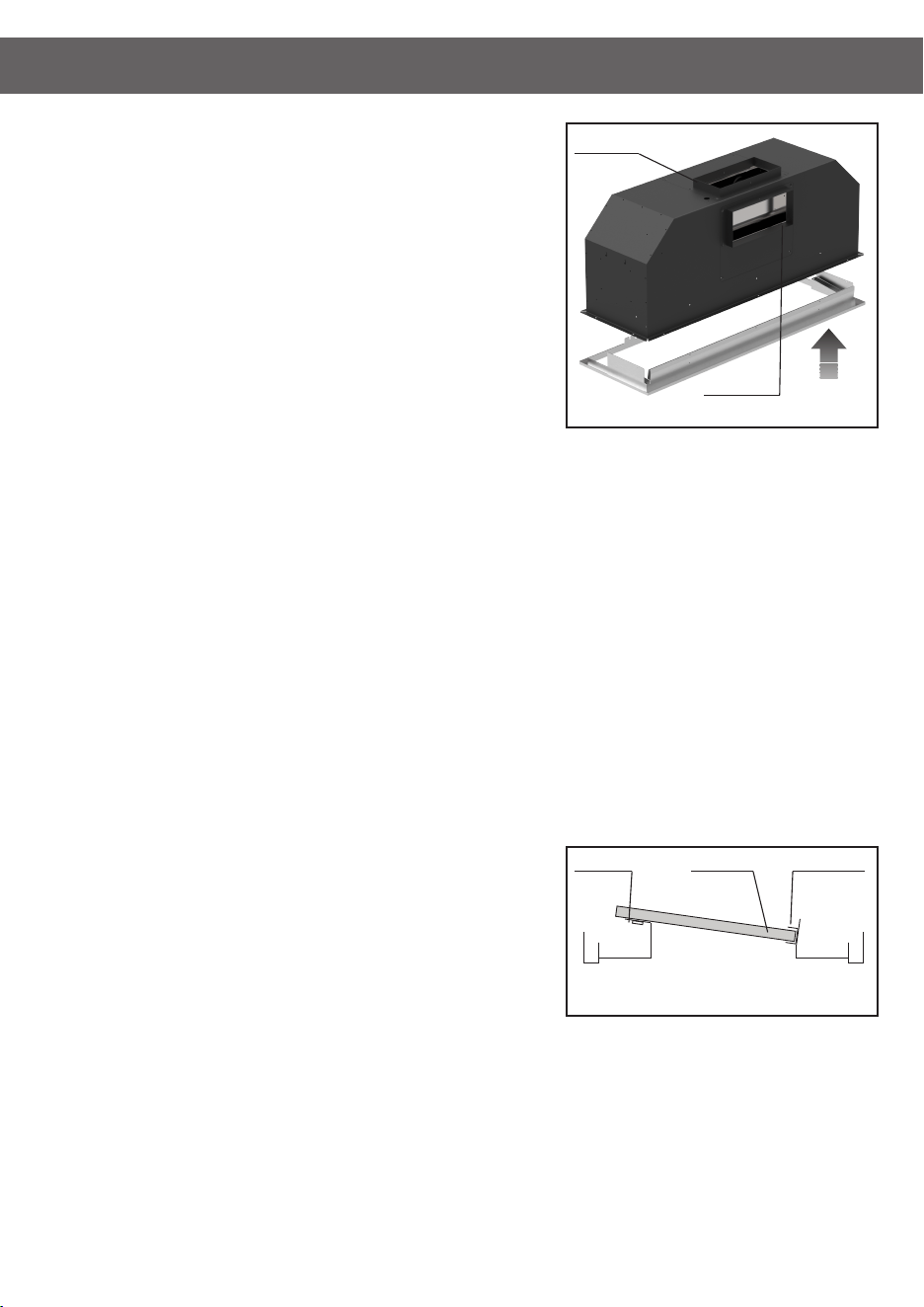
STEP 5:
Using the ten (10) xing holes, screw the Main Chassis into position.
STEP 6:
Once the Main Chassis is secured into the cabinetry, the Fascia can then be slid
back inside the Main Chassis. Replace the screws (removed in Step 3) to x the
Fascia back into positon. Replace the grease trap.
STEP 7:
Please note all Whispair rangehoods are required to be vented to the outside
atmosphere.
Top Ducting - Place the supplied transition rectangle to round (X1DK.TRANS) on
the top of the outlet of the rangehood. On the 200mm outlet on the top of the duct
attach either rigid or exi-duct (not supplied) and continue this installation through
the roof space to be vented through to an eave, wall or roof vent. It is critical to
maintain the 200mm throughout the installation and keep the ducting as straight
and tight as possible to the outlet vent position.
Back Ducting - On the rectangle outlet on the back of the rangehood, feed the
supplied 320mm long ducting (X1DK.WVENT or X1DK.WVENT150) through the
hole created in step 2 from the outside of the home. Depending on the thickness
of the wall, reduce the length of the rectangle duct by cutting. Fit the supplied wall
vent inside the rectangle duct and mount into place using the pre-drilled xing
holes on the vent as a guide.
STEP 8:
Attach the male power plug of the rangehood unit to mains power supply. Note to
electricians: Standard 10 Amp General Power Outlet (GPO) required. Position GPO
as close to the hood unit as possible.
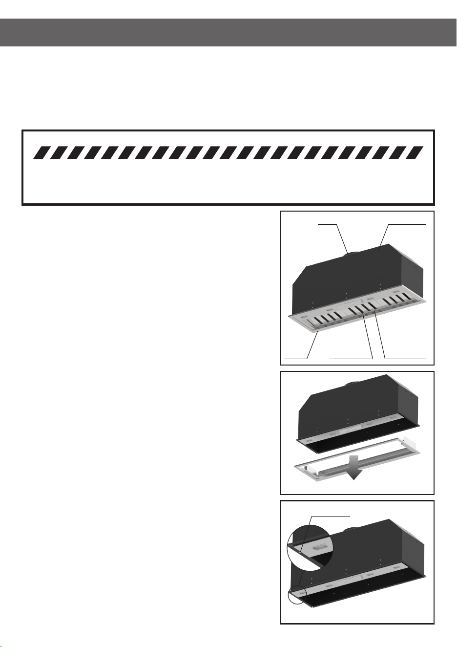
INSTALLING THE GREASE TRAP AND BAFFLE FILTERS:
All WHISPAIR hoods utilise removable bafe lters and grease trap. This ltration
system is used to catch by-products such as grease and moisture from the air ow.
To install the bafe lters, simply locate the lter on the top ledge of the hood and
then slide the lter on a downward angle to rest in the channel of the grease trap.
Ensure the lter vane are aligned towards the rear of the hood.
Most by-products are captured and stored directly in the bafe lters however the grease trap may begin to ll when excess amounts of
grease and condensate build up in the lter vanes.
The grease trap can be removed for cleaning by removing the two (2) screw xings in the channel.
To clean your bafe lters and grease trap please wash with warm soapy water or simply place in the dishwasher for convenience. Please
note that the edge’s of the lters can be sharp and caution should be taken when removing or cleaning by hand.
It is recommended the bafe lters and grease trap are cleaned every 4 weeks to reduce the risk of re.
Bafe Filter and Grease Trap Position
Top Ledge
Bafe Filter Grease Trap
Front Rear
Step 7: Insert Fascia into Main Chassis
Top Ducted
Back Ducted
PART 1: HOOD INSTALLATION GUIDE
8
STEP 1:
Measure the height (H1) of the hood from the base to the top of the Mounting
Hooks.
NOTE:
The height (H2) of the underside of the hood body must be a minimum of
600mm above an electric cooktop, for a gas cooktop a minimum of 650mm
measured from the supporting surface of the trivet for the cooking vessels
(excluding the wok support) to the underside of the hood body and a maximum
height of 1000mm.
Building codes that stipulate a minimum dimension may vary from state to state,
please check with your local council prior to installation.
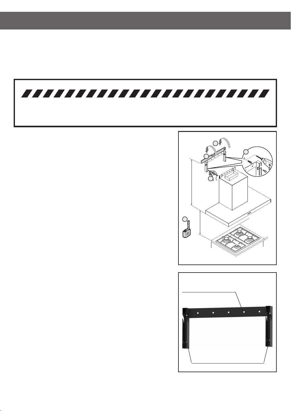
STEP 2:
Using a spirit level mark a vertical centre line on the wall where the Mounting
Bracket needs to be positioned. It is recommended to centre the hood unit to the
cooktop below.
STEP 3:
Mark a horizontal line on the wall for the Mounting Bracket position. Centre and
mark the four (4) xing points in the vertical section on the left and right side of
the bracket. Drill and plug holes with suitable sized wall plugs (not provided).
STEP 4:
Fix the Mounting Bracket with four (4) suitable screws into the wall at the
positions marked in step 3 to allow the body of the hood to be hung on the wall.
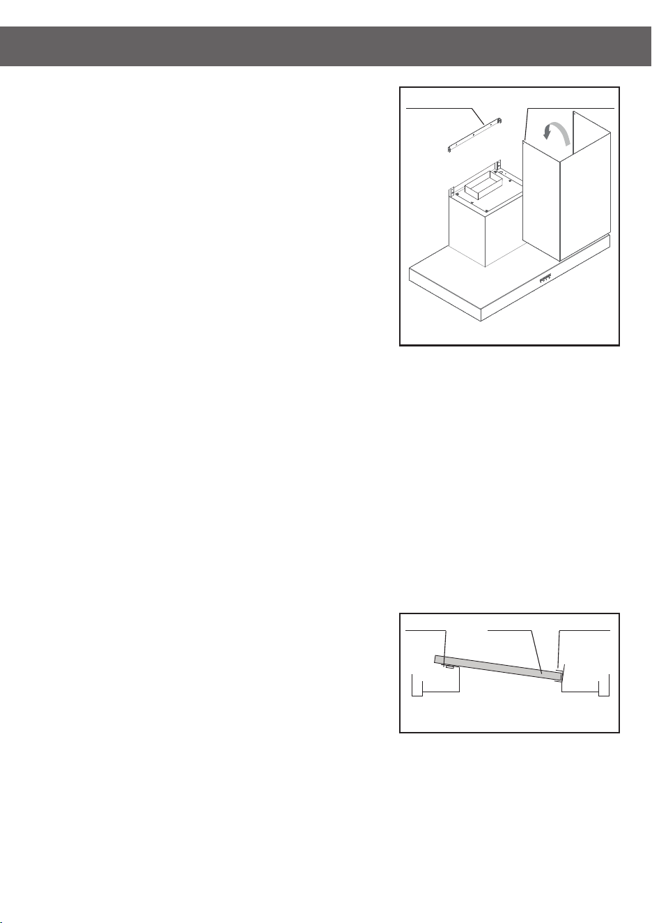
STEP 5:
Hang the hood on the wall ensuring the Mounting Hooks are securely positioned
into the Mounting Bracket.
STEP 6:
Secure the hood to the wall by screw xing through the ve (5x) holes on the
horizontal plate of the Mounting Bracket.
Wall Mounting Bracket
Hood Fixing Holes (5x) - Step 6
Wall Fixing Holes (4x) - Step 4
1
2
3
5
4
H1
H2
Wall Hung Canopy Hood with Integrated Fan Motor
Models Included: X5L09S5.OP(/T/B), X5L09S6.OU(/T/B), X5S06S5.OP(/T/B), X5S06S6.OU(/T/B), X5S09S5.OP(/T/B),
X5S09S6.OU(/T/B), X5R09S5.OP(/T/B), X5R09S6.OU(/T/B), X5R09W5.OP(/T/B), X5R09W6.OU(/T/B), X5V09S5.OP(/T/B),
X5V09S6.OU(/T/B), X5V12S6.OU(/T/B), X5Z09S5.OP/T, X5Z09S6.OU/T, X5Z12S5.OP/T, X5Z12S6.OU/T, X5A12S6.2OU/T,
X5A15S6.2OU/T, X5A18S6.2OU/T
WARNING
FAILURE BY THE INSTALLER TO INSTALL THE SCREWS OR FIXING DEVICES IN ACCORDANCE WITH THESE INSTALLATION
INSTRUCTIONS MAY RESULT IN ELECTRICAL HAZARDS. DIMENSIONS ARE ACCURATE AT THE TIME OF PRINTING, HAUS
GROUP RESERVES THE RIGHT TO CHANGE SPECIFICATIONS WITHOUT NOTICE. FOR BUILDING PURPOSES THE UNIT
SHOULD BE PROVIDED TO THE CABINET MAKER / BUILDER / KITCHEN DESIGNER FOR EXACT MEASUREMENTS.
PART 1: HOOD INSTALLATION GUIDE
9
STEP 7:
Secure the Chimney Bracket to the wall.
STEP 8:
Please note all Whispair rangehoods are required to be vented to the outside
atmosphere.
Top Ducting - Place the supplied transition rectangle to round (X1DK.TRANS) on
the top of the outlet of the rangehood. On the 200mm outlet on the top of the duct
attach either rigid or exi-duct (not supplied) and continue this installation through
the roof space to be vented through to an eave, wall or roof vent. It is critical to
maintain the 200mm throughout the installation and keep the ducting as straight
and tight as possible to the outlet vent position.
Back Ducting - On the rectangle outlet on the back of the rangehood, feed the
supplied 320mm long ducting (X1DK.WVENT or X1DK.WVENT150) through the
hole created in step 2 from the outside of the home. Depending on the thickness
of the wall, reduce the length of the rectangle duct by cutting. Fit the supplied wall
vent inside the rectangle duct and mount into place using the pre-drilled xing
holes on the vent as a guide.
STEP 9:
Place the stainless steel chimney on the hood and secure to the Chimney Bracket
with the two (2) screws supplied. If the chimney is required to be lengthened the
second internal chimney can be added, telescoping to the required height. If the
chimney is required to be shortened, new holes may need to be drilled to secure
the chimney cover.
STEP 10:
Attach the male power plug of the rangehood unit to mains power supply. Note to
electricians: Standard 10 Amp General Power Outlet (GPO) required. Position GPO
as close to the hood unit as possible.
INSTALLING THE GREASE TRAP AND BAFFLE FILTERS:
All WHISPAIR hoods utilise removable bafe lters and grease trap. This ltration
system is used to catch by-products such as grease and moisture from the air ow.
To install the bafe lters, simply locate the lter on the top ledge of the hood and
then slide the lter on a downward angle to rest in the channel of the grease trap.
Ensure the lter vane are aligned towards the rear of the hood.
Most by-products are captured and stored directly in the bafe lters however the grease trap may begin to ll when excess amounts of
grease and condensate build up in the lter vanes.
The grease trap can be removed for cleaning by removing the two (2) screw xings in the channel.
To clean your bafe lters and grease trap please wash with warm soapy water or simply place in the dishwasher for convenience. Please
note that the edge’s of the lters can be sharp and caution should be taken when removing or cleaning by hand.
It is recommended the bafe lters and grease trap are cleaned every 4 weeks to reduce the risk of re.
Bafe Filter and Grease Trap Position
Top Ledge
Bafe Filter Grease Trap
Front Rear
Chimney Bracket Chimney Fixing Points
Step 9: Chimney Installation
PART 1: HOOD INSTALLATION GUIDE
10
STEP 1:
Using a weighted string line (plumb line), determine the central position of
hood on the ceiling. It is recommended to centre the hood unit to the cooktop
below. Mark the position. Before making the cut out, check for obstructions
like electrical cables, etc.
NOTE:
The height of the underside of the hood body must be a minimum of 600mm
above an electric cooktop, for a gas cooktop a minimum of 650mm measured
from the supporting surface of the trivet for the cooking vessels (excluding the
wok support) to the underside of the hood body and a maximum height of
1000mm.
For installation over a BBQ, the hood can be installed between 1000mm and
1200mm above the cooking surface. Building codes that stipulate a minimum
dimension may vary from state to state, please check with your local council
prior to installation.
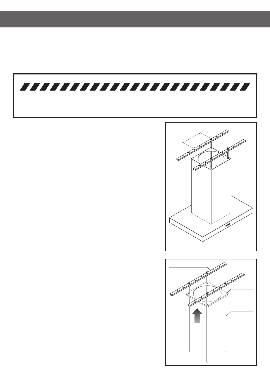
STEP 2:
Place the two (2) supplied supporting metal beams (1000mm long) with
pre-drilled xing holes perpendicular (90o) to the roof trusses.
STEP 3:
Fit the four (4) supplied 10mm threaded rod through the holes provided on the
supporting metal beams and secure with nuts and washers provided. Ensure
the rod drop height is sufcient to attach the hood and nut xings but is not
excessive that is will impede the placement of the lters.
STEP 4:
Feed the Ceiling Plate up the threaded rod and x into position with nuts
provided ensure a rm t to the ceiling.
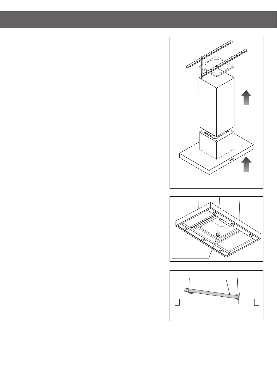
STEP 5 (OPTIONAL):
For additional stability add a second Ceiling Plate (optional) half way between the
ceiling and the hood. This will give the mounting additional stability which may
be benecial for longer chimney runs.
Threaded Rod
Ceiling Plate
Supporting Metal Beams
Step 4
300mm
Island Hung Canopy Hood or Ceiling Cassette with Integrated Fan Motor
Models Included: X7S09S5.OP/T, X7S09S6.OU/T, X7R09S5.OP/T, X7R09S6.OU/T, X7R09W5.OP/T, X7R09W6.OU/T,
X7V09S5.OP/T, X7V09S6.OU/T, X7V12S6.OU/T, X7P04S5.OP/T, X7P04S6.OU/T, X7P05S5.OP/T, X7P05S6.OU/T,
X7Z09S5.OP/T, X7Z09S6.OU/T, X7Z12S5.OP/T, X7Z12S6.OU/T, X7ZD09S6.OU/T, X7ZD12S6.2OU/T, X7H09S5.OP/T,
X7H09S6.OU/T, X7H12S5.OP/T, X7H12S6.OU/T, X9C12S5.OP(/T/B), X9C12S6.OU(/T/B)
WARNING
FAILURE BY THE INSTALLER TO INSTALL THE SCREWS OR FIXING DEVICES IN ACCORDANCE WITH THESE INSTALLATION
INSTRUCTIONS MAY RESULT IN ELECTRICAL HAZARDS. DIMENSIONS ARE ACCURATE AT THE TIME OF PRINTING, HAUS
GROUP RESERVES THE RIGHT TO CHANGE SPECIFICATIONS WITHOUT NOTICE. FOR BUILDING PURPOSES THE UNIT
SHOULD BE PROVIDED TO THE CABINET MAKER / BUILDER / KITCHEN DESIGNER FOR EXACT MEASUREMENTS.
PART 1: HOOD INSTALLATION GUIDE
11
STEP 6:
Lift the stainless steel chimney into position and secure to the Ceiling Bracket with
the four (4) screws supplied. If the chimney is required to be shortened, new holes
may need to be drilled to secure the chimney cover.
STEP 7:
Please note all Whispair rangehoods are required to be vented to the outside
atmosphere.
Top Ducting - Place the supplied transition rectangle to 200mm round
(X1DK.TRANS) rectangle outlet Ultra 1680 motor only on the top of the outlet of the
rangehood. With the 150mm outlet Power 1020 motor units attach on the top of
the duct either rigid or semi rigid (either not supplied) and continue this installation
through the roof space to be vented through to an eave, wall or roof vent. It iscritical
to maintain the ducting size, be it 150mm or 200mm throughout the installation
and keep the ducting as straight and tight as possible to the outlet vent position.
STEP 8:
Lift and attach the hood unit to the base of the threaded rod with the provided nuts
and washers. Level the unit off by tensioning the 10mm nuts. Being mindful not to
over tighten.
Minimise how much threaded rod is below the nut. Excess
threaded rod may interfer with the bafe lters.
STEP 9:
Feed any excess exi-ducting back into the ceiling space ensuring that any excess
gathering of ducting is pulled tight. Loose and gathered ducting will reduce the
extraction levels.
STEP 10:
Attach the male power plug of the rangehood unit to mains power supply. Note to
electricians: Standard 10 Amp General Power Outlet (GPO) required. Position GPO
as close to the hood unit as possible.
INSTALLING THE GREASE TRAP AND BAFFLE FILTERS:
All WHISPAIR hoods utilise removable bafe lters and grease trap. This ltration
system is used to catch by-products such as grease and moisture from the air ow.
To install the bafe lters, simply locate the lter on the top ledge of the hood and
then slide the lter on a downward angle to rest in the channel of the grease trap.
Ensure the lter vane are aligned towards the rear of the hood.
Most by-products are captured and stored directly in the bafe lters however the grease trap may begin to ll when excess amounts of
grease and condensate build up in the lter vanes.
The grease trap can be removed for cleaning by removing the two (2) screw xings in the channel.
To clean your bafe lters and grease trap please wash with warm soapy water or simply place in the dishwasher for convenience. Please
note that the edge’s of the lters can be sharp and caution should be taken when removing or cleaning by hand.
It is recommended the bafe lters and grease trap are cleaned every 4 weeks to reduce the risk of re.
Lift Chimney
Into Position
(Step 6)
Lift Hood
Into Position
(Step 8)
Hood Mounting Points
Bafe Filter and Grease Trap Position
Top Ledge
Bafe Filter Grease Trap
Front Rear
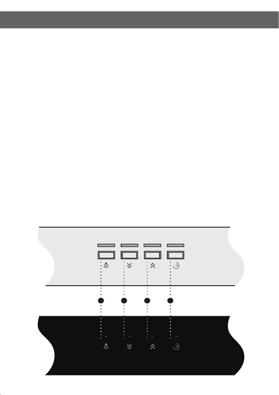
OPERATION
Operating your 4-button control panel
Models included: Electronic Control or Touch Control
12
TURNING THE EXTRACTION FUNCTION ON OR OFF:
• In standby mode, press button 2 or 3 to change the speed.
• The hood has three speed options and a 4th boost speed (4 speeds in total).
• The LED indicators directly above the buttons indicates the speed setting selected.
• To turn hood off, press button 2 repeatedly until hood returns to standby mode.
• Auto off function: After 2 hour of operation without alteration the fan motor will turn off (returned to standby).
TURNING THE LIGHT FUNCTION ON OR OFF:
Press button 1 to turn on or turn off the light independently in standby mode.
TURNING THE TIMER FUNCTION ON OR OFF:
In operating mode, press button 4 to engage the timer function, then press button 2 or 3 to adjust the delay time.
The default timer is set to 10mins and can be increased in increments of 10mins up to 1 hour (i.e. 4 pushes of button 3 will result
in timer set to 50mins before shut off).
When the timer is rst activated, the LED positioned behind button 4 (timer) will ash quickly to indicate the time setting i.e. for
30mins remaining the LED will blink 3 times quickly. When the timer function is engaged the (timer) LED positioned behind button
4 (timer) will blink slowly until the timer expires.
1 2 3 4
PRODUCT CARE
13
It is recommended that your WHISPAIR rangehood and all of its items be cleaned regularly.
Before any cleaning or maintenance work, disconnect the cooker hood from the mains power supply.
CLEANING THE STAINLESS STEEL HOOD UNIT
• It is expected that the stainless steel is cleaned with a quality non-abrasive stainless steel cleaner.
• Use a soft cloth for application.
• It is recommended that this is performed every 4 weeks.
CLEANING THE KLEENAIR FAN MOTOR UNIT
• The KLEENAIR unit should be checked regularly to ensure that nothing is obstructing the air ow from the housing.
• If there are obstructions, please remove the debris ensuring the product returns to the manufacturer’s intended operating
condition.
CLEANING THE BAFFLE FILTERS AND GREASE TRAP
• The bafe lters and grease trap can be removed from the mounted position within the hood and washed in the dishwasher
or by hand.
• Use hot water and liquid detergent.
• After cleaning, leave the lters and trap to dry before placing back in the hood.
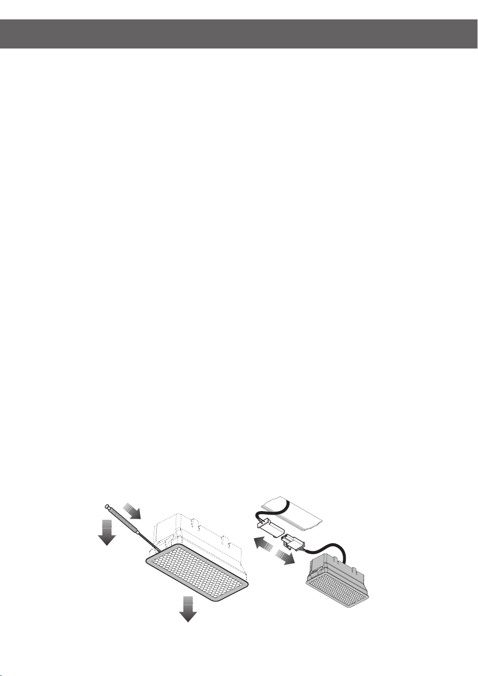
WARNING WHEN CHANGING THE LED LAMP
Please be aware that whilst in use LED lighting units may become hot and the surrounding area may remain hot for some time
after switching off. Please allow the lamp area to cool before operating near the lighting.
REPLACEMENT OF LED LAMP
• Make sure the main power supply into hood is disconnected at the GPO.
• Using a ne at blade, wedge the LED unit from the insert whilst applying pressure to the locking tab.
• Disconnect the 12V connectors.
• Replace with a new unit and push back inside the cut outs in the fascia.
• Please replace only with a genuine unit available from Haus Group Australia Pty Ltd.

14
WARRANTY
Every WHISPAIR rangehood comes with a 5-Year parts and labour warranty. This warranty is conditional upon the appliance
being used only for personal, domestic and household purposes and installed and operated in accordance with WHISPAIR
instructions.
The consumer is responsible for any charges associated with removal of the faulty unit and installation of the new unit.
The customer may also be responsible for any freight charges incurred in this change over process.
The installation of WHISPAIR rangehoods must comply with the information in the guide. Installation of the rangehood must be in
a covered area, to avoid direct weathering. Failure to follow the guidelines will result in loss of warranty.
We recommend our customers use an authorised WHISPAIR installer.
Any imperfections in the nishes or in the natural materials used should not be considered as faults but a typical characteristic
of these crafted products.
Should you ever need to make a warranty related enquiry about your WHISPAIR product, in Australia simply call Haus Group
Australia on +61 (0) 3 8593 9600 or New Zealand on +64 (0) 9 887 6959 to speak with our friendly customer service team
consultants. We suggest you have the following information close at hand to make the process as easy as possible:
1. Model number of your complete rangehood and motor unit
2. A copy of your WHISPAIR proforma invoice
3. Address details of where the appliance has been installed
Any associated or ancillary costs to be incurred by you as a result of replacement or repair of your WHISPAIR rangehood under
this guarantee shall, in all cases, be previously approved by Haus Group Australia Pty Ltd or Haus Group New Zealand Ltd.
Please note: The benets provided under this warranty are additional to other rights and remedies available to the customer
under the Australian or New Zealand Customer Law.
Our goods come with guarantees that cannot be excluded under the Australian or New Zealand Consumer Law. You are entitled
to a replacement or a refund for a major failure and for compensation for any other reasonably foreseeable loss or damage. You
are also entitled to have the goods repaired or replaced if the goods fail to be of acceptable quality and the failure does not
amount to a major failure.
YOUR STATUTORY RIGHTS

15
NOTES

16
NOTES
head office.
Haus Group Australia Pty Ltd
F4/19 Columbia Court
DANDENONG SOUTH Victoria Australia 3175
Australia.
t. (AU) 03 8593 9600 f. (AU) 03 8593 9699
w. www.hausgroup.com.au
New Zealand.
t. (NZ) 09 887 6959 f. (NZ) 09 887 6958
w. www.hausgroup.co.nz
Print Version: W_25_S6_04