
COLUMN REFRIGERATION
RBCFVL-18, RBCFVR-18,
RBCFV-24, RBCRV-24, &
RBCRV-30 MODELS
zlinekitchen.com
Installation Manual

ZLINE Kitchen and Bath provides Attainable Luxury, where the kitchen and bath of your dreams is
never out of reach. Through our unique designs and unparalleled quality, we’re dedicated to providing
you an elevated experience in the heart of your home. With an endless selection of features and
finishes, our inspiration is your reality.

ZLINE is fueled by a passion for innovation; A relentless pursuit of bringing the
highest end luxury designs and professional features into everyone’s homes.
Because we continually strive to improve our products, we may change
specifications and designs without prior notice.
Scan the QR code to view the most up-to-date version of the Installation Manual
and User Manual.
WARNING: This product can expose you to chemicals including nickel, which is known to the
State of California to cause cancer. For more information, go to www.P65Warnings.ca.gov.

TABLE OF CONTENTS
IMPORTANT SAFETY INSTRUCTIONS . . . . . . . . . . . . . . . . . . . . . . . 1
BEFORE INSTALLATION . . . . . . . . . . . . . . . . . . . . . . . . . . . . . . . . . . . 9
Tools Required . . . . . . . . . . . . . . . . . . . . . . . . . . . . . . . . . . 9
Preparation for Installation and Cabinet Cutouts . . . . . . . . . . . . . . . 11
Location of the Electrical Wiring . . . . . . . . . . . . . . . . . . . . . . . .13
Location of the Water System . . . . . . . . . . . . . . . . . . . . . . . . .14
Product Dimensions . . . . . . . . . . . . . . . . . . . . . . . . . . . . . . .18
Door Opening Dimensions . . . . . . . . . . . . . . . . . . . . . . . . . . . 19
Detailed Dimensions . . . . . . . . . . . . . . . . . . . . . . . . . . . . . 20
Parts Provided . . . . . . . . . . . . . . . . . . . . . . . . . . . . . . . . . .25
INSTALLATION . . . . . . . . . . . . . . . . . . . . . . . . . . . . . . . . . . . . . . . . . 28
Mounting the Anti-Tip Brackets . . . . . . . . . . . . . . . . . . . . . . . . .29
Preparing for Placing the Unit into the Cabinet . . . . . . . . . . . . . . . 35
Preparing Door Panels . . . . . . . . . . . . . . . . . . . . . . . . . . . . .54
Installing the Door Panel . . . . . . . . . . . . . . . . . . . . . . . . . . . .59
Changing the Direction of the Refrigerator Door . . . . . . . . . . . . . . 69
DUAL CABIN INSTALLATION . . . . . . . . . . . . . . . . . . . . . . . . . . . . .83
WARRANTY . . . . . . . . . . . . . . . . . . . . . . . . . . . . . . . . . . . . . . . . . . . . 96
1
PLEASE READ THIS MANUAL BEFORE INSTALLING AND USING THE PRODUCT
• Always follow the applicable safety instructions.
• The installer should leave these instructions with the consumer who should retain for local
inspectors’ use and for future reference.
• Please read all other documents provided with this product.
• Please keep in mind this manual may apply to several product models.
• This manual expressly indicates the differences between various models.
• IMPORTANT: This is a complex installation procedure that should only be performed by
qualified professionals and technicians.
• The manufacturer will not be responsible for any damage to property or to persons caused
by incorrect installation, improper use of the appliance, or failure to heed the warnings listed.
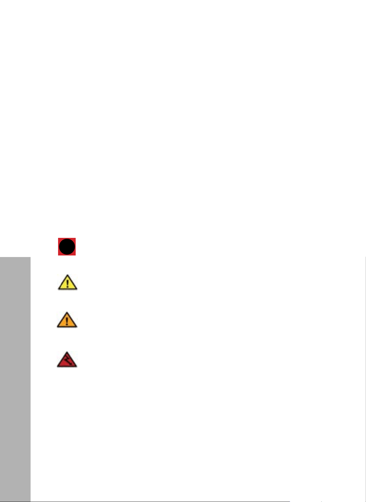
Symbols used in the installation manual are as follows.
i
Important information and useful hints.
INFO
Conditions that may damage the product or its operating functions.
WARNING
ATTENTION
Conditions containing serious injury risk.
CAUTION
Conditions containing electric shock risk.
IMPORTANT SAFETY INSTRUCTIONS
General Safety
2
R600A REFRIGERANT
This product contains R600a isobutane refrigerant, which is a very eco-
friendly natural gas. However, it is also flammable. Please follow the
warnings and installation instructions below:
• If the product has been transported horizontally, you must wait a minimum
of 4 hours after standing it upright before plugging it in.
• Cut-out dimensions of the installation area must be suitable to safely fit the
product for full installation.
• Dimensions, features, and position of objects used to support and affix the
product to this area must be suitable.
• Minimum clearances between product parts and surrounding structures
must be suitable.
• Minimum dimensions and proper organization of ventilation holes must
be observed.
• The product must be connected to the main power outlet, and corresponding
connections of other components must be suitable.
• The product must be able to be disconnected from the power supply if
needed after installation.
• The outlet or fuse must be accessible to disconnect the product.
• Extension cables or ungrounded (two-terminal) adapters must not be used
with this unit.
WARNING
ATTENTION
You must wear gloves and eye protectors when installing the product.
You must also take measures against high noise levels when using a drill to
drill into the floor or wall.
ATTENTION
Make sure that your product is suitable for your local codes.
ATTENTION
The product must be installed by a qualified technician according to the
installation instructions.
The product may tip over since it is quite heavy. For this reason, safety
precautions must be taken. The doors of the product must be kept closed
until it reaches the final install destination, and it must be transported in
accordance with the installation instructions.
WARNING
IMPORTANT SAFETY INSTRUCTIONS
Refrigerant Safety
3
IMPORTANT SAFETY INSTRUCTIONS
DISPOSING OF THE PACKAGING MATERIALS
• The package has been designed to protect the product during transport and shipping.
The packaging materials used are designed to not harm the environment and should be
recycled after the appliance is installed.
• All plastic packaging materials, bags, etc., must be disposed of safely and kept out of the
reach of children.
This Installation Manual has been prepared to help qualified professionals
with installation of the appliance. The User Manual provided with the product
must also be taken into consideration, as it contains important information
about operation and safety. You may get seriously injured and your product
may get damaged if you ignore the warnings given in this manual. Please read
the following carefully.
WARNING
Risk of child entrapment. To avoid safety and suffocation risks for children or
pets, before you dispose of the appliance, take off the doors and drawers and
leave the shelves in place so children or pets may not climb inside.
WARNING
COMPLIANCE WITH THE WEEE DIRECTIVE AND DISPOSING OF E-WASTE
• This product conforms to the EU WEEE Directive (2012/19 EU).
• This product bears a classification symbol for "waste electrical and electronic
equipment," otherwise known as WEEE.
• This product has been manufactured from high-quality parts and materials
that can be reused and are suitable for recycling.
• Therefore, do not dispose of the product with normal domestic waste or other waste at the
end of its service life.
• Take it to a collection center for recycling electrical and electronic equipment.
• Please consult your local government authority to learn about appropriate collection
center location.
Disposing of Materials
4
CLIMATE CLASS
The ambient temperature must be between 61 °F and 90 °F (16 °C and 32 °C). These appliances
have been designed to be used in certain climate ranges (ambient temperatures). They must not
be used out of this range. Otherwise, function errors may arise when the product is running.
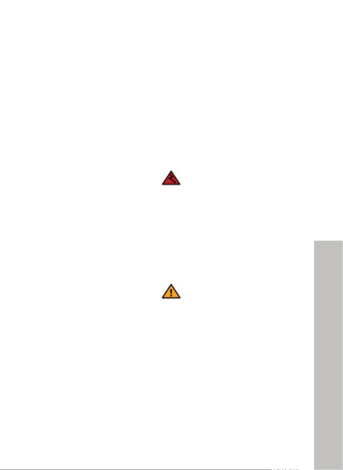
LOAD BEARING CAPACITY OF THE DOORS
CATEGORY RBCFVL-18/ RBCFVR-18 RBCFV-24 RBCRV-24 RBCRV-30
MAX LOAD 22 Ib (10 kg) 33 Ib (15 kg)
!"#$%&'#(%)*! !
'"
"
"
!"#$%&'#()*+%,#-#,)./%"0%.1'%$""(%&)*2%%%%%%%%%%
% %
%
%
%
%
%
!"#$%&'() *+,-./01+02) *+,34/01+02) *5,34/01+02) *5,67/01+02)
8"9):&";) 330<=)>-7?%@) 660<=)>-A?%@) 660<=)>-A?%@) AA0<=)>37?%@)
Max load
Max load
RBCFVL-18/RBCFVR-18
Confidential
6
Load bearing capacity of the door bins
Category
TF-18BINFIA
TF-24BINFIA
TL-24BINFIA
TL-30BINFIA
Max load
22Ibs (10kg)
33Ibs (15kg)
33Ibs (15kg)
55Ibs (20kg)
RBCFV-24/RBCRV-24/RBCRV-30
Max load
IMPORTANT SAFETY INSTRUCTIONS
Climate Class and Weight

5
INSTALLATION ENCLOSURE
You must follow the instructions below:
• The floor on which the product will be installed must be capable of bearing a minimum of
1,200 pounds (544 kilograms).
• The kitchen floor and bottom of the product must be at the same level. Otherwise, the air
flow for the unit's cooling system may be impeded or reduced.
• There must be no objects preventing installation of the product to the back and side walls of
the product's cut-out installation area.
• The electrical outlet receptacle must be properly located and easily accessed.
• Cut-out dimensions of the cabinets where the product will be installed must be in strict
conformity with the dimensions given in this manual.
• Do not install a refrigerator or freezer directly adjacent to another unit unless using the
appropriate joining kit. Otherwise, condensation and damage may occur. (Please see
"Dual Cabin Installation" on page 10 for imagery.)
• Check if the floor where the product will be installed is level. Use a level when doing
so to be sure.
• The installation area must not be subjected to direct sunlight and it must be away from heat
sources, such as microwaves, ovens, radiators, etc.
• The ambient temperature must be between 61 °F and 90 °F (16 °C and 32 °C),
depending on where the unit is installed. Otherwise, function errors may occur when the
product is running.
• If it is not possible to avoid installing the product near a heat source, the minimum clearances
given below must be maintained:
• 2" (51 mm) from electric ranges or ovens.
• 12" (305 mm) from gas or fuel operated ranges or ovens.
IMPORTANT SAFETY INSTRUCTIONS
Preparing the Installation Enclosure
6
IMPORTANT SAFETY INSTRUCTIONS
Please observe the following rules:
• The dedicated circuit breaker for this unit must be easily accessible in case of an emergency;
it must not be hidden behind the product.
• The electrical plug and cord must not touch the back surface of the product. Otherwise, it
may get damaged due to the vibration of the product.
• Do not plug in other appliances behind this product.
• If the humidity level is high where the product is used, corrosion may occur on the outer
surface of the product. Keep the area where the unit will be installed dry and well-cleaned
to avoid corrosion.
CAUTION
To avoid the risk of electric shock:
• Connect the plug to a dedicated grounded electrical outlet.
• Do not remove the ground terminal of the plug.
• Do not use adapters.
• Do not use extension cables or cords.
ATTENTION
Do not install your refrigerator or freezer:
• In open areas.
• In environments where water is dripping.
• In environments where temperature is lower than 61 °F (16 °C).
Preparing the Installation Enclosure

7
IMPORTANT SAFETY INSTRUCTIONS
ATTENTION
Failure to follow these instructions may result in death, fire, or electric shock.
Connecting the grounding conductor of the equipment to an improper
place may lead to electric shock. Please have the grounding checked by a
qualified electrician or service technician.
Installation, repair, and other procedures performed by unqualified
persons may cause danger. Before installing the appliance, make sure that
the voltage, load, and circuit current parameters on the data plate are in
compliance with the power mains in your house.
The appliance is provided with a NEMA 5-15P plug and a 3-pin power
cable, which is UL listed and ready to be connected to a 120 VAC, 60 Hz
power supply. The fuse is 15 amps, and the appliance must be connected to
a dedicated electrical outlet.
If combining multiple units, ZLINE recommends all be plugged into
independent circuits. They can be plugged into the same outlet, but the
circuit must have a dedicated 15-amp breaker.
If the electrical wiring or power supply of the house needs alteration,
the necessary procedures must be performed by a qualified electrician.
The plug must be installed only by a licensed electrician.
CABINETS
•
Make sure that the cabinets where you will install the appliance have been safely mounted
in your kitchen. Your cabinets must be securely connected to the floor and walls properly
and with suitable connections.
• For the best installation, clearances between the cabinets and the product must be in
compliance with the values specified in the installation instructions of this manual.
• Side walls must be free of any obstructions and their surfaces must be flat.
• NOTE: Minimum thickness of the side walls is 5/8" (16 mm). The minimum thickness of the
doors to be attached to the product must be 3/4" (19 mm). For a 25" (635 mm) flush inset
depth, the maximum door panel thickness is 15/16" (24 mm).
Preparing the Installation Enclosure
8
VENTILATION
Ventilation panels where the air enters and exits the unit must not be blocked or obstructed. In
addition, you must periodically clean the dust and dirt that accumulates on the vent holes to
ensure adequate ventilation.
ELECTRICAL CONNECTION
• Never use an extension cable or cord with this unit.
• The dedicated electrical outlet receptacle for this unit must be grounded and checked by an
authorized electrician.
• The location of the electrical wiring must comply with the dimensions specified in this
installation manual.
CAUTION
RISK OF ELECTRIC SHOCK
Electrical grounding is necessary. This appliance is equipped with a 3-pin plug
to protect you against possible electric shocks.
• Do not remove the round grounding terminal from the plug.
• Do not use 2-pin grounding adapters.
• Do not use extension cables or cords to energize the product.
ATTENTION
Do not connect the grounding cable to any gas pipes. Please have the grounding
checked by a qualified electrician if you are not sure about the grounding of
the product. Do not install a fuse on the neutral line or grounding circuit.
Please wait 3-6 hours after installing the unit before plugging it in to protect it
against possible damages. This way, the refrigerant and the lubricants in the
system are given proper time to balance.
WARNING
WATER CONNECTION
The pressure of the main water supply must be in compliance with the values specified in this
manual, and the location of the water system must comply with the dimensions specified in
this manual.
i
Using the provided water filter bypass plug is recommended for the unit's water
filtering system if a reverse osmosis system is used. Reference the User Manual
for directions on how to install the water filter and/or the bypass plug.
INFO
IMPORTANT SAFETY INSTRUCTIONS
Electrical Connection
9
TOOLS REQUIRED
Tools to be used when installing the product are as follows (additional tools that may assist in
installation are not listed here):
TOOLS REQUIRED (NOT PROVIDED)
• Cordless Drill
• Safety Goggles
• 1/2" Wrench
• Hammer
• Ladder
• 3/32" Drill Bit
• 5/16" Drill Bit
• Box Cutter
• Socket Wrench
• Safety Gloves
• Tape Measure
• 1/4" Torx Bit
• 1/4" Flat Wrench
• 1/4" Hex Bit
• Level
• Dolly or Hand Truck
• Tape
ALTERNATIVES FOR INSTALLATION
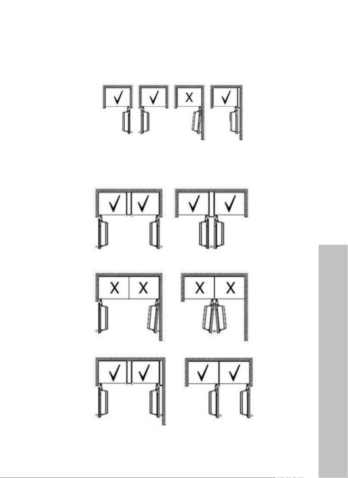
• The product can be placed in various ways based on the kitchen design. It must be installed
at a place where it is ensured that the door can be opened and closed properly.
• If the doors cannot be opened 90° at least, you cannot completely open the drawers inside
the product. NOTE: The unit's hinges are designed to allow doors to open up to 115°.
BEFORE INSTALLATION
Tools Required
10
SINGLE CABIN INSTALLATION METHODS
DUAL CABIN INSTALLATION METHODS
BEFORE INSTALLATION
Cabin Installation Methods
11
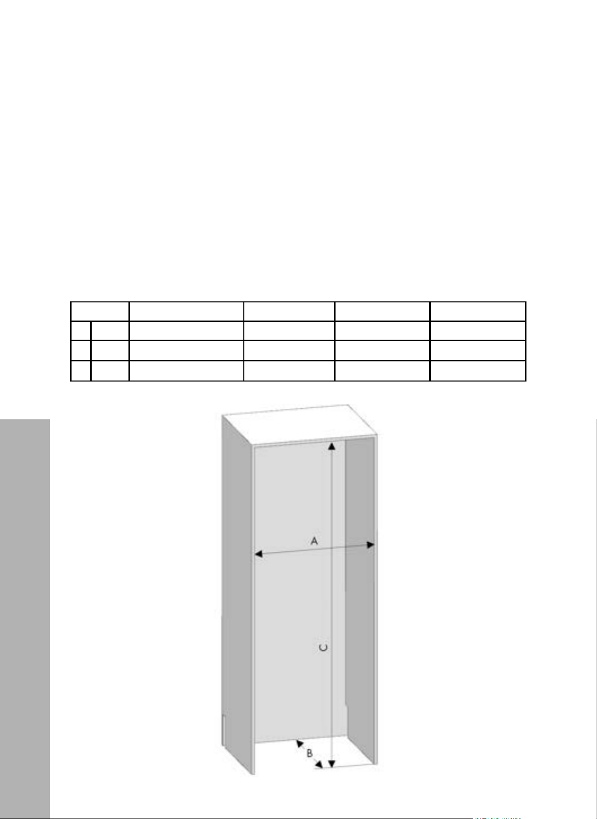
PREPARATION FOR INSTALLATION AND CABINET CUTOUTS
• ZLINE column refrigerators and freezers are panel-ready appliances designed to be a
permanent kitchen fixture; therefore, precise cutouts and superior attention to detail are
required for seamless integration, especially if custom panels are installed. The most common
scenario is the unit is installed between two kitchen cabinets or decorative columns.
• The refrigerator comes with a 2 9/16" (65 mm) stainless steel toe kick installed to fit a
standard 84" (2134 mm) tall cabinet.
• NOTE: Kitchen layouts may vary, so recommended dimensions must be confirmed by a
qualified technician before starting the installation.
Category RBCFVL-18/RBCFVR-18 RBCFV-24 RBCRV-24 RBCRV-30
A Width 18 3/16" (462 mm) 24 3/16" (614 mm) 24 3/16" (614 mm) 30 3/16" (769 mm)
B Depth 25" (635 mm) 25" (635 mm) 25" (635 mm) 25" (635 mm)
C Height 84" (2134 mm) 84" (2134 mm) 84" (2134 mm) 84" (2134 mm)
BEFORE INSTALLATION
Cabinet Cutout
12
Cabinetry Planning
BEFORE INSTALLATION
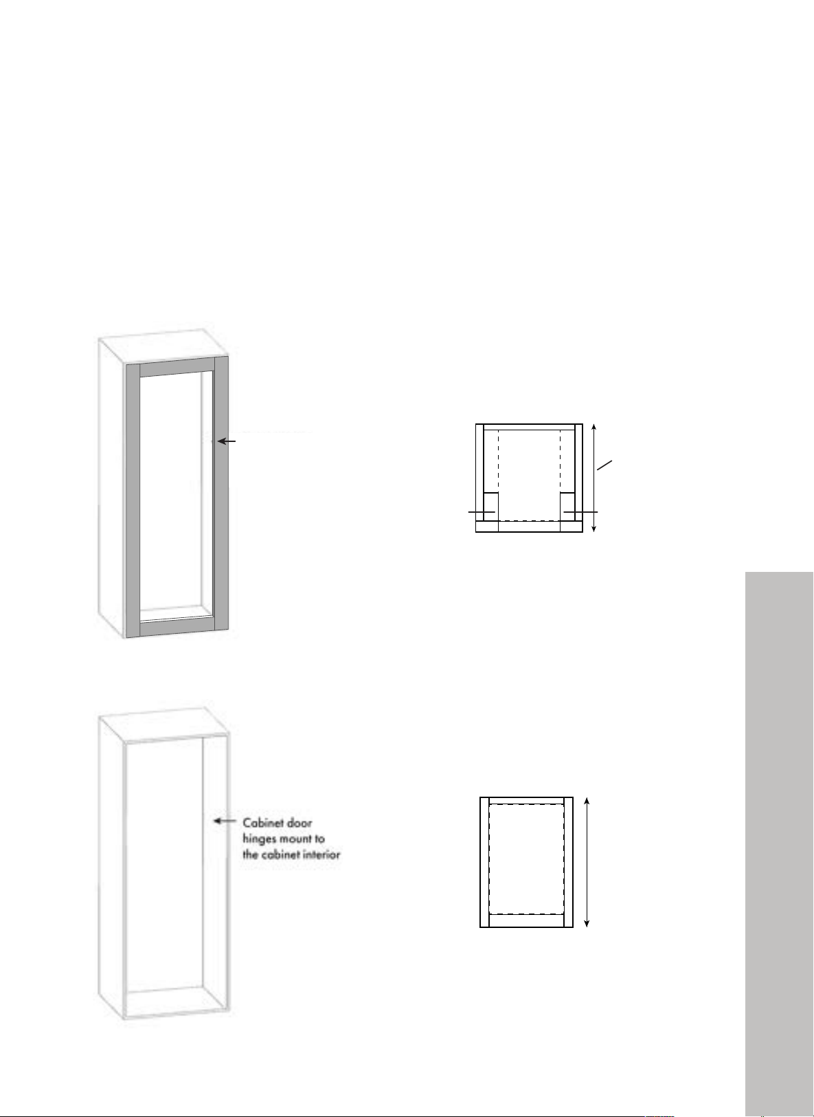
CABINETRY PLANNING
NOTE: If you have an existing framed cabinet, you need to add a filler behind the face frame in
order to properly mount the side brackets. If you don't have a filler, you'll have a gap and won't
be able to safety install your unit(s).
FRAMED CABINET
Cabinet door
hinges mount to
the face frame
Filler required with a
finished return on both
sides of the appliance.
Filler required with a
finished return on both
sides of the appliance.
Door panel
25" (635 mm)
Cutout depth
Appliance
Door panel
25" (635 mm)
Cutout depth
Appliance
FRAMELESS CABINET
Filler required with a
finished return on both
sides of the appliance.
Filler required with a
finished return on both
sides of the appliance.
Door panel
25" (635 mm)
Cutout depth
Appliance
Door panel
25" (635 mm)
Cutout depth
Appliance
13
Location of Electrical Wiring
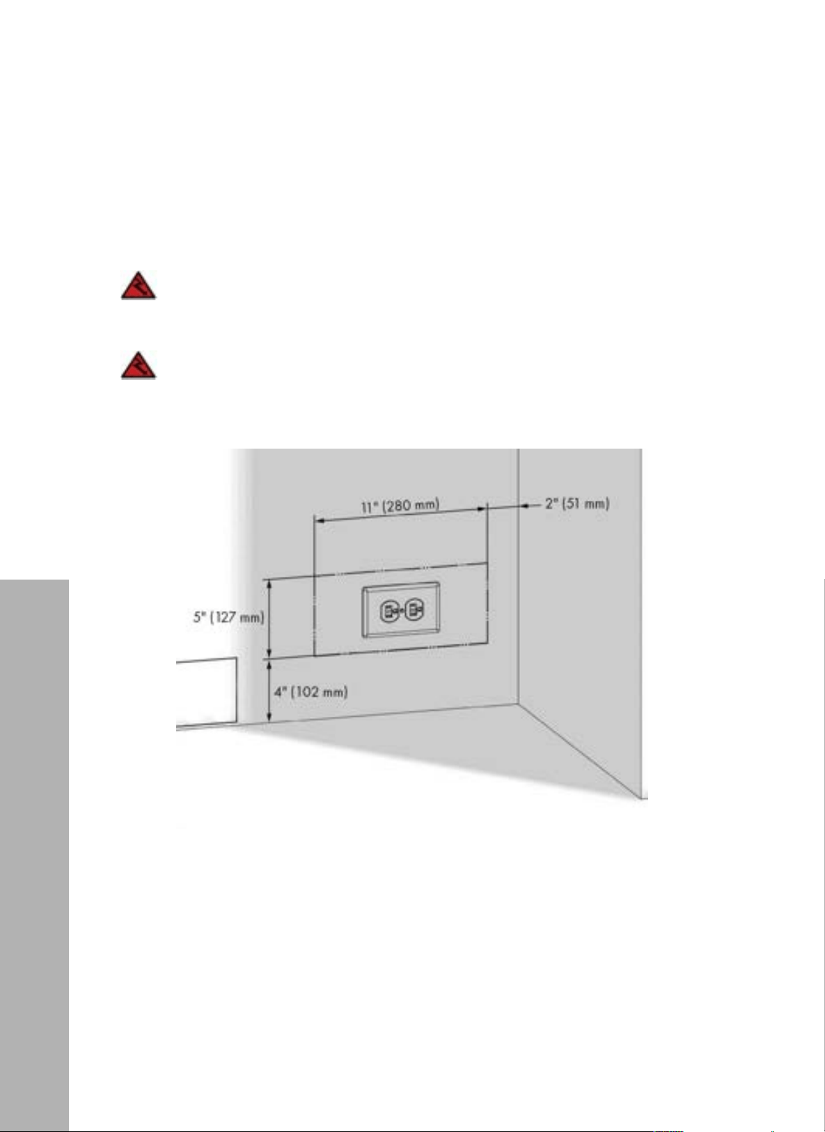
LOCATION OF THE ELECTRICAL WIRING
• The location of the electrical outlet must be within the range provided below.
• Using an outlet with a ground fault circuit interrupter (GFCI) is not recommended.
CAUTION
Do not use extension cables or cords or 2-pin adapters, and do not remove the
ground terminal of the grounding cable.
CAUTION
A qualified electrician must ensure that the poles of the socket are connected
correctly. A qualified electrician must also verify that the grounding of the
socket is correct.
BEFORE INSTALLATION
14
Location of Water System
BEFORE INSTALLATION
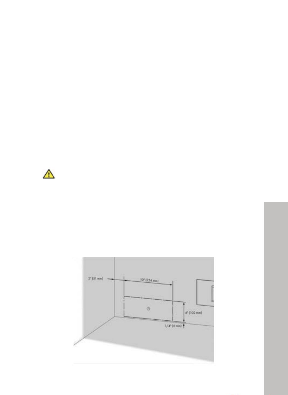
LOCATION OF THE WATER SYSTEM
• The water connected to the unit must be potable.
• The location of the water system must be within the range provided below.
• The unit's water system must be connected to the main water system in the house. The user
must be able to switch the water system on/off with a valve when necessary.
• Objects that may pierce the water hoses or cause them to twist must not be present where
the water line is installed.
• Pressure of the water system must be between 25-80 psi (1.7-5.5 bar).
• If the water pressure exceeds 80 psi (5.5 bar), install a pressure-limiting device or water
pressure protector to the inlet valve. Never install or operate the appliance if it's possible for
the water pressure to exceed 120 psi (8.3 bar).
• Make sure there is no leakage when making water connections. Otherwise,
there will be water on the floor and the cabinets may get damaged.
• You will need a hose with a minimum length of 60" (1524 mm) and a
diameter of 1/4" (6 mm) for water connections of the product during
installation.
• A connector that has a thread with an external diameter of 1/4" (6 mm)
must be used to connect the hose end to the product.
• Before completing installation, make sure water flows and there is no
leakage. Damage may occur if leaks are present.
WARNING
15
Dual Cabin Electrical Location
BEFORE INSTALLATION
DUAL CABIN ELECTRICAL AND WATER REQUIREMENTS
• Each appliance is provided with a NEMA 5-15P plug and a 3-pin power cable designed
to be connected to a 120 VAC, 60 Hz power receptacle.
• Therefore, we recommend both units be plugged into independent circuits. They can be
plugged into the same outlet, but please note the circuit must have a dedicated 15-amp
breaker that is not shared with any other appliance to avoid exceeding the combined
power requirements.
• From a water standpoint, while both units also come with their own water supply, a
qualified technician can easily tee off the water supply to provide water to both units if the
customer desires.
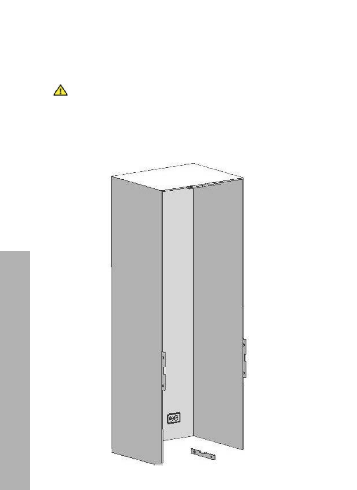
• Refer to the diagrams below and on the following page, and please refer to the earlier
sections for additional information for electrical and water requirements and other
installation needs.
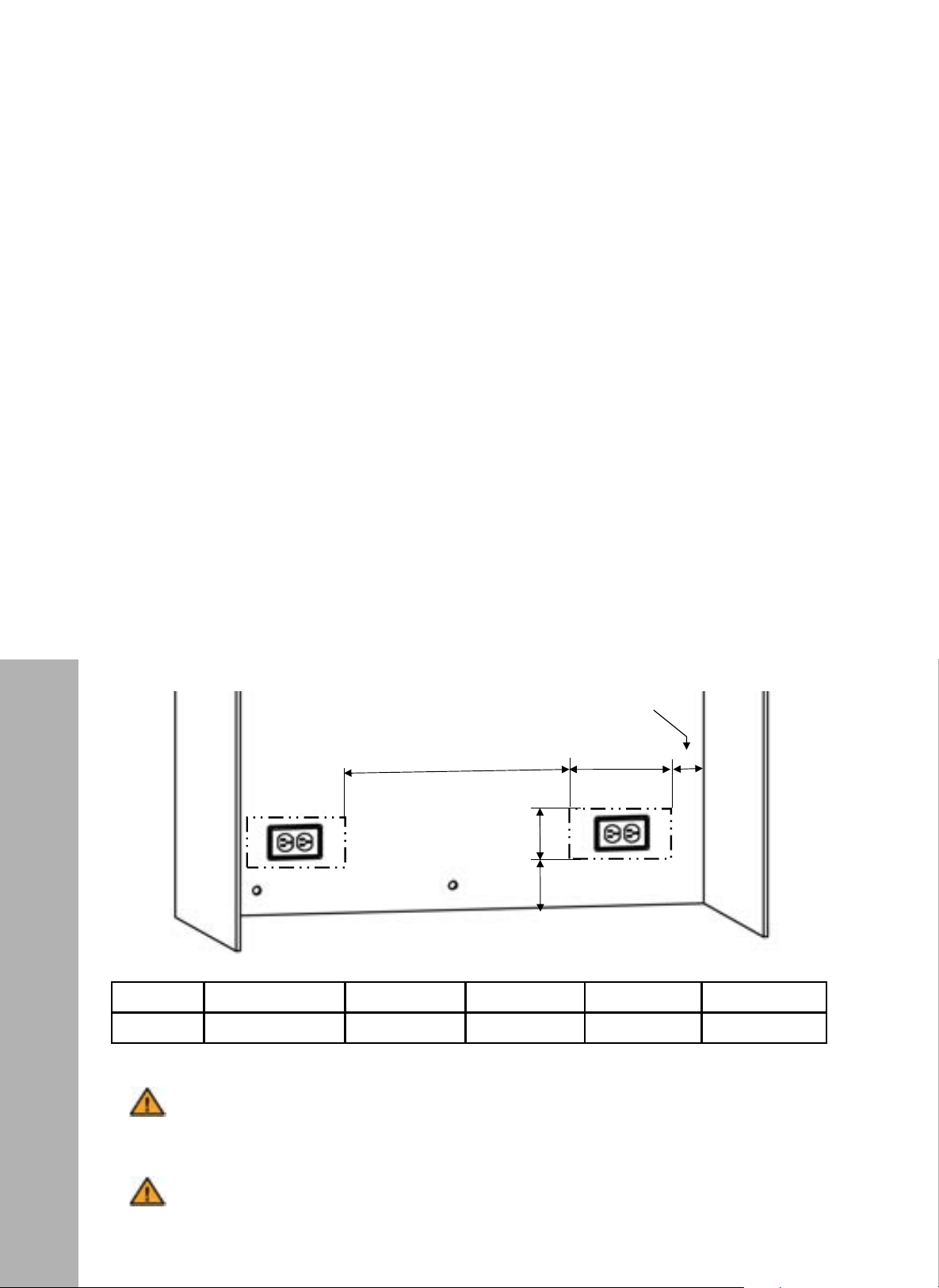
ELECTRICAL LOCATION
• Location of electrical wiring must be within the range given below.
• Using an outlet with a ground fault circuit interrupter (GFCI) is not recommended.
4" (102 mm)
11" (280 mm)
2
"
51mm)
5" (127 mm)
A
Category 18" + 24" 18" + 30" 24" + 24" 24" + 30" 30" + 30"
A 13" (330 mm) 19" (482 mm) 13" (330 mm) 19" (482 mm) 19" (482 mm)
ATTENTION
Do not use extension cables or two-pin adapters and do not remove the ground
terminal of the grounding cable.
ATTENTION
A qualified electrician must ensure that the poles of the socket are connected
correctly and that the appliance is properly grounded.
16
Dual Cabin Water System Location
BEFORE INSTALLATION
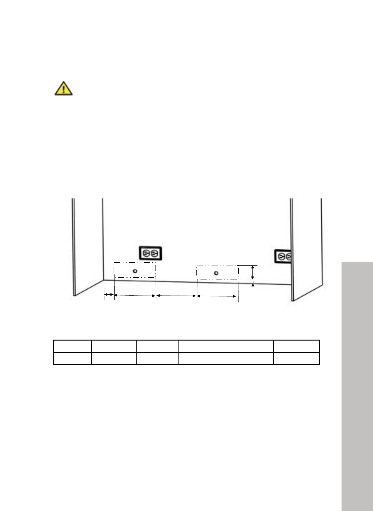
DUAL CABIN WATER SYSTEM LOCATION
• Make sure there is no leakage when making water connections. Otherwise,
there will be water on the floor and the cabinets may get damaged.
• You will need a hose with a minimum length of 60" (1524 mm) and a
diameter of 1/4" (6 mm) for water connections of the product during
installation.
• A connector that has a thread with an external diameter of 1/4" (6 mm)
must be used to connect the hose end to the product.
• Before completing installation, make sure water flows and there is no
leakage. Damage may occur if leaks are present.
WARNING
!"#$%&'#(%)*
! !
)+"
"
!",#.)"*%"0%.1'%F#.'(%2/2.'H% !
678"L3>8:"@0448@>85">0">78"L3>8:".3942".M2>"/8"?0>3/18<" "
B0@3>904"0K">78"L3>8:"2-2>8.".M2>"/8"L9>794">78":34;8";9Q84"/810L<" "
X3>8:"2-2>8."0K">78":8K:9;8:3>0:".M2>"/8"@0448@>85">0">78"L3>8:".3942"2-2>8."94">78"70M28<" "
678"M28:".M2>"/8"3/18">0"2L9>@7"9>"04g0KK"L9>7">78"Q31Q8"L784"48@8223:-<" "
H/V8@>2">73>".9;7>"?98:@8">78"L3>8:"70282"0:"@3M28">78.">0">L92>".M2>"40>"/8"?:8284>" "
L78:8">78"L3>8:"1948"92"942>31185<" "
"
I:822M:8"0K">78"L3>8:"2-2>8.".M2>"/8"/8>L884"#&R)+"?29"`!<(R&<&"U3:a<" "
=K">78"L3>8:"?:822M:8"8_@8852")+"?29\"942>311"3"?:822M:8"19.9>94;"58Q9@8"0:"L3>8:"9.?3@>"?:0>8@>0:">0">78"9418>"Q31Q8<"
E8Q8:"942>311">78"?:05M@>"0:"0?8:3>8">78"3??1934@8"9K"9>"92"?0229/18"K0:">78"L3>8:"?:822M:8">0"8_@885"!#+"?29<
+
+
!
!"#$%$&'(
S3P8"2M:8">73>">78:8"92"40"L3>8:"183P3;8"L784".3P94;">78"L3>8:"@0448@>9042<" "
H>78:L928\">78:8"L911"/8"L3>8:"04">78"K100:"345">78"KM:49>M:8"L911";8>"53.3;85<" "
]0M"L911"4885"3"7028"L9>7"3".949.M."184;>7"0K"'+e"`!<&".8>8:2a"345"3"593.8>8:"0K"me" "
K0:"L3>8:"@0448@>9042"0K">78"?:05M@>"5M:94;"942>3113>904<" "
A"@0448@>0:">73>"732"3">7:835"L9>7"34"8_>8:431"593.8>8:"0K"m".M2>"/8"M285">0"@0448@>">78"7028"845">0">78"?:05M@><"
U8K0:8"@0.?18>94;">78"942>3113>904\".3P8"2M:8">73>"L3>8:"K10L2"345">78:8"92"40"L3>8:"183P3;8<"
+
+
+
+
+
+
+
+
+
+
+
+
+
+
+
+
+
+
+
+
+
+
+
+
+
+
+
+
+
+
+
+
+
+
+
+
+
+
+
+
+
./012345+ !"D&#+ !"D,(+ &#D&#+ &#D,(+ ,(D,(+
E*F+=@>1AG@3A+ "F+H&(,>>I+ "F+H&(,>>I+ !#F+H,$'>>I+ !#F+H,$'>>I+ &(F+H$(">>I+
T.) /G1-445!
-I) /0123445!
G1I) /-0T445
!
KH3.) /-G445!
#) I) !
G1I) /-0T445!
2" (51 mm)
10" (254 mm)
A
10" (254 mm)
13/16" (21 mm)
4" (102 mm)
Category 18" + 24" 18" + 30" 24" + 24" 24" + 30" 30" + 30"
A 8" (203 mm) 8" (203 mm) 14" (356 mm) 14" (356 mm) 20" (508 mm)
17
Installation Location
PRODUCT PLACEMENT
• Check if the floor where the appliance will be installed is perfectly level.
Use a level as shown below.
• Check if the cabinet flanges are upright and straight using a level.
• If the product is not level and plumb, problems may arise with installation
and eventual operation of the unit.
WARNING
BEFORE INSTALLATION
18
Product Dimensions
BEFORE INSTALLATION
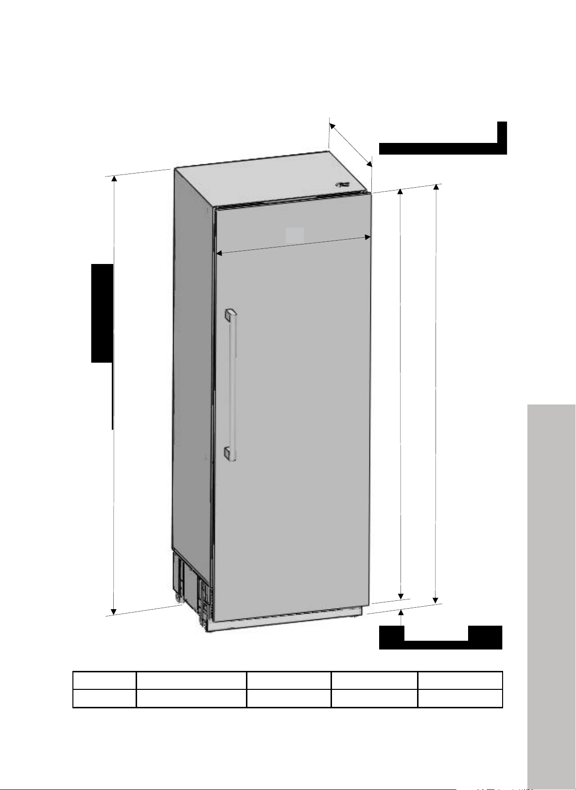
PRODUCT DIMENSIONS
!"#$%&'#(%)*! !
!'"
"
?0%+C64(+/#.*'/%*'(
"
+
+
+
+
+
"
)
+ +
+
+++++++++++++++++++++++++++
+
5:&26;<=!
*+,-./01+02) *+,34/01+02) *5,34/01+02) *5,67/01+02)
*+
!%+,-#(!)#$!**+! &,+,-#(!)'(,**+! &,+,-#(!)'(,**+!
0>!,?8@!).4/**+!
BC)-AD-E,)>3767FF@!
.6)CD-E
,)>3-36FF@!
GH#I&J#)K"L$:) ) M)36)AD-E
,))>AC3FF@!
GH#I)K"L$:))M))34)-,)>E-EFF@) !
6)AD.,)>C6FF@!
.6)CD-E,)>3-36@!
2
!
83 9/16" (2123 mm)
3 5/8" (93 mm)
Without panel: 23 5/16" (592 mm)
With panel: 24 1/4" (616 mm)
A
83 9/16" (2123 mm)
79 15/16" (2030 mm)
Category RBCFVL-18/RBCFVR-18 RBCFV-24 RBCRV-24 RBCRV-30
A 17 3/4" (451 mm) 23 3/4" (603 mm) 23 3/4" (603 mm) 29 3/4" (756 mm)
19
BEFORE INSTALLATION
PRODUCT DIMENSIONS
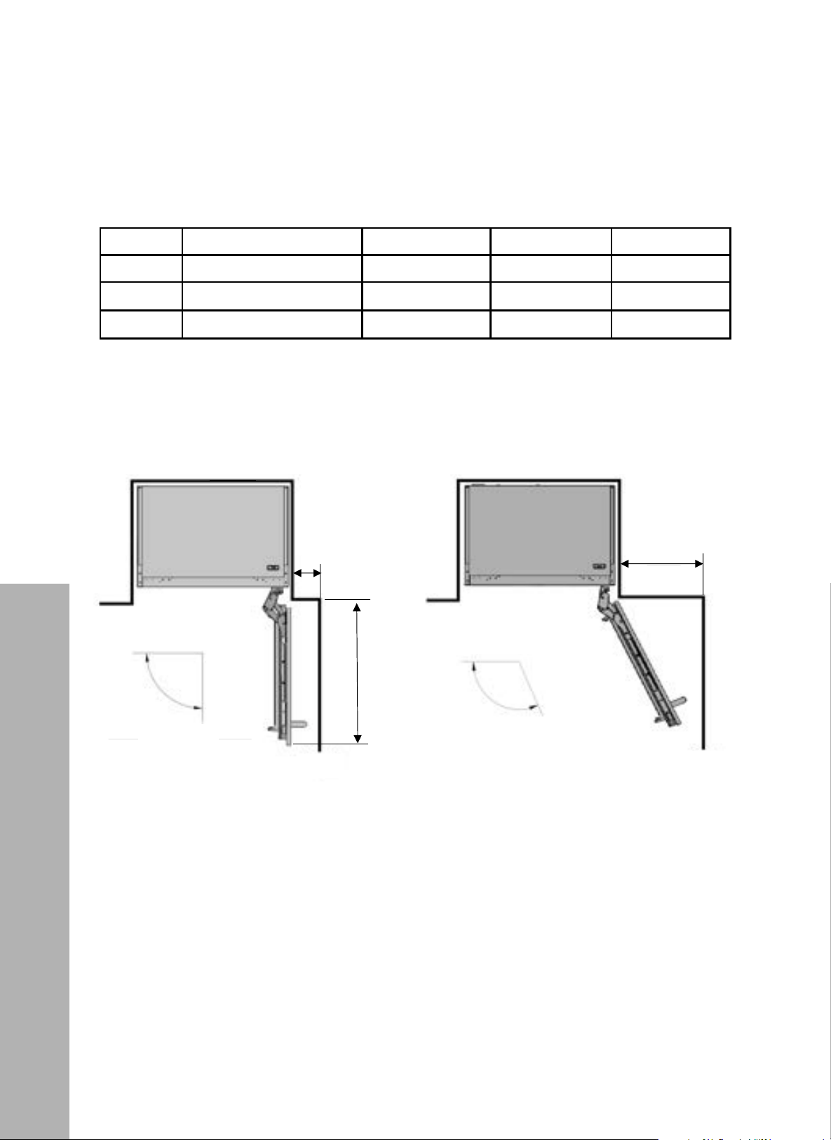
DOOR OPENING DIMENSIONS
Category RBCFVL-18/RBCFVR-18 RBCFV-24 RBCRV-24 RBCRV-30
A 20" (508 mm) 26" (660 mm) 26" (660 mm) 32" (813 mm)
B 4 3/8" (110 mm) 4 3/8" (110 mm) 4 3/8" (110 mm) 4 3/8" (110 mm)
C 11" (280 mm) 14" (356 mm) 14" (356 mm) 16" (406 mm)
A: Depth of door (90°open) measured from front of door
B: Minimum door clearance to adjacent wall (90°- reduced internal access)
C: Minimum door clearance to adjacent wall (115°- full internal access)
!"#$%&'#(%)*! !
!("
"
;B<?C!!C?;>B%D;E8B<;>B%
!
!
!
!
!
!
A"["Y8?>7"0K"500:"`*+!0?84".832M:85"K:0."K:04>"0K"500:" "
U"["S949.M."500:"@183:34@8">0"35V3@84>"L311"`" " *+!R" " :85M@85"94>8:431"3@@822a"
J"["S949.M."500:"@183:34@8">0"35V3@84>"L311"`" " !!&!R""KM11"94>8:431"3@@822a" "
!
!
!
!
!
!
!
!
!
!
!
!
!
!
!
!
!
!
!
!
!
!
!
!
!
!
!
!
!
!
!
!"#$%&'() *+,-./01+02)
*+,34/01+02) *5,34/01+02)
*5,67/01+02)
2) 37N) >A7.@) 3EN) >EE7@) 3EN) >EE7@) 63N) >.-6@)
/) 4)6D.N) >--7@) 4)6D.N) >--7@) 4)6D.N) >--7@)
4)6D.N) >--7@)
!) --N) >3.7@) -4N) >6AE@) -4N) >6AE@)
-EN) >47E@)
C7
.
O&&')=GHL%
!
!!
"!
#!
--A.O&&')=GHL%!
B
A
90° Door swing
115 ° Door swing
Wall
Wall
C
Product Dimensions
20
BEFORE INSTALLATION
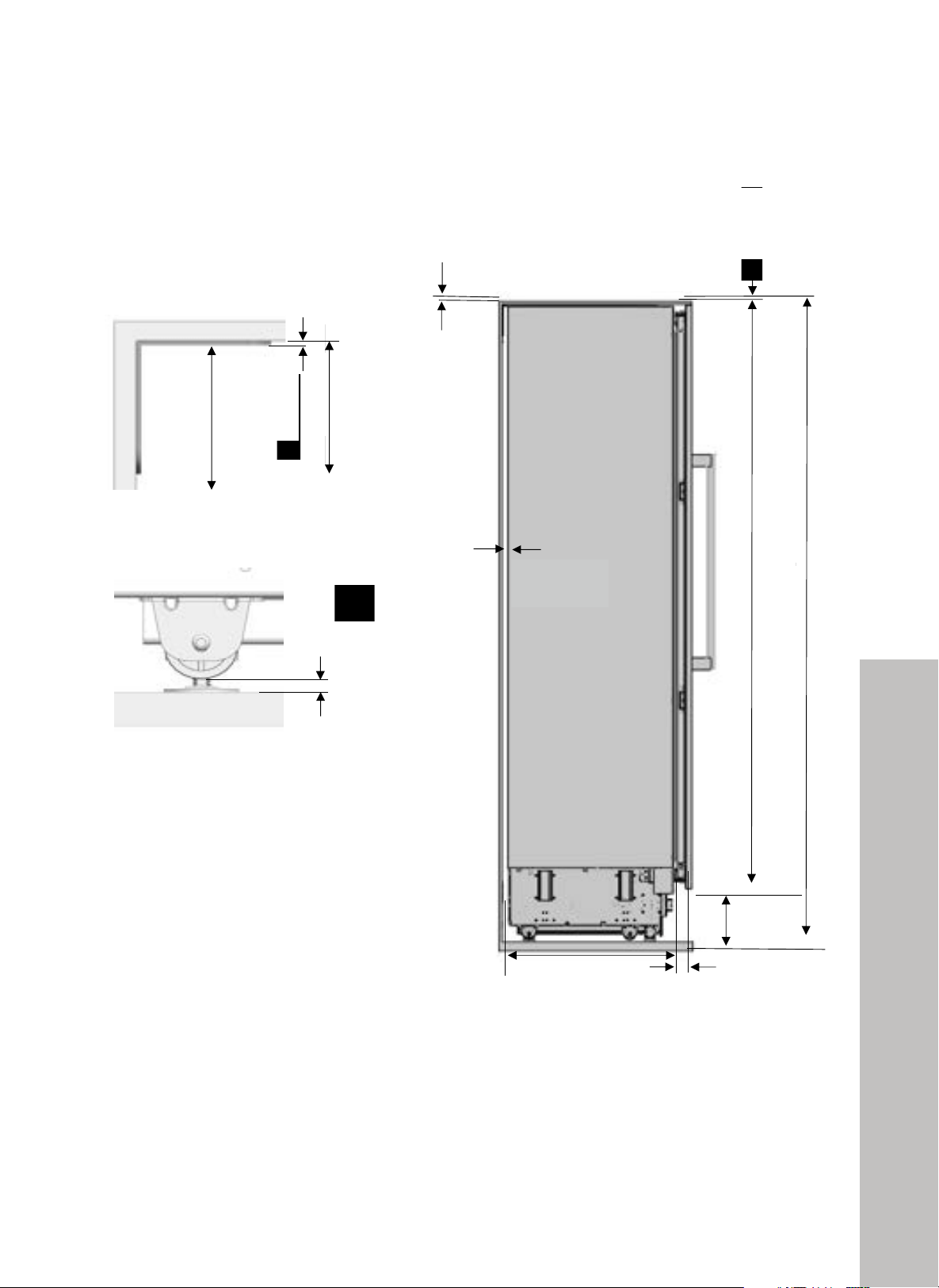
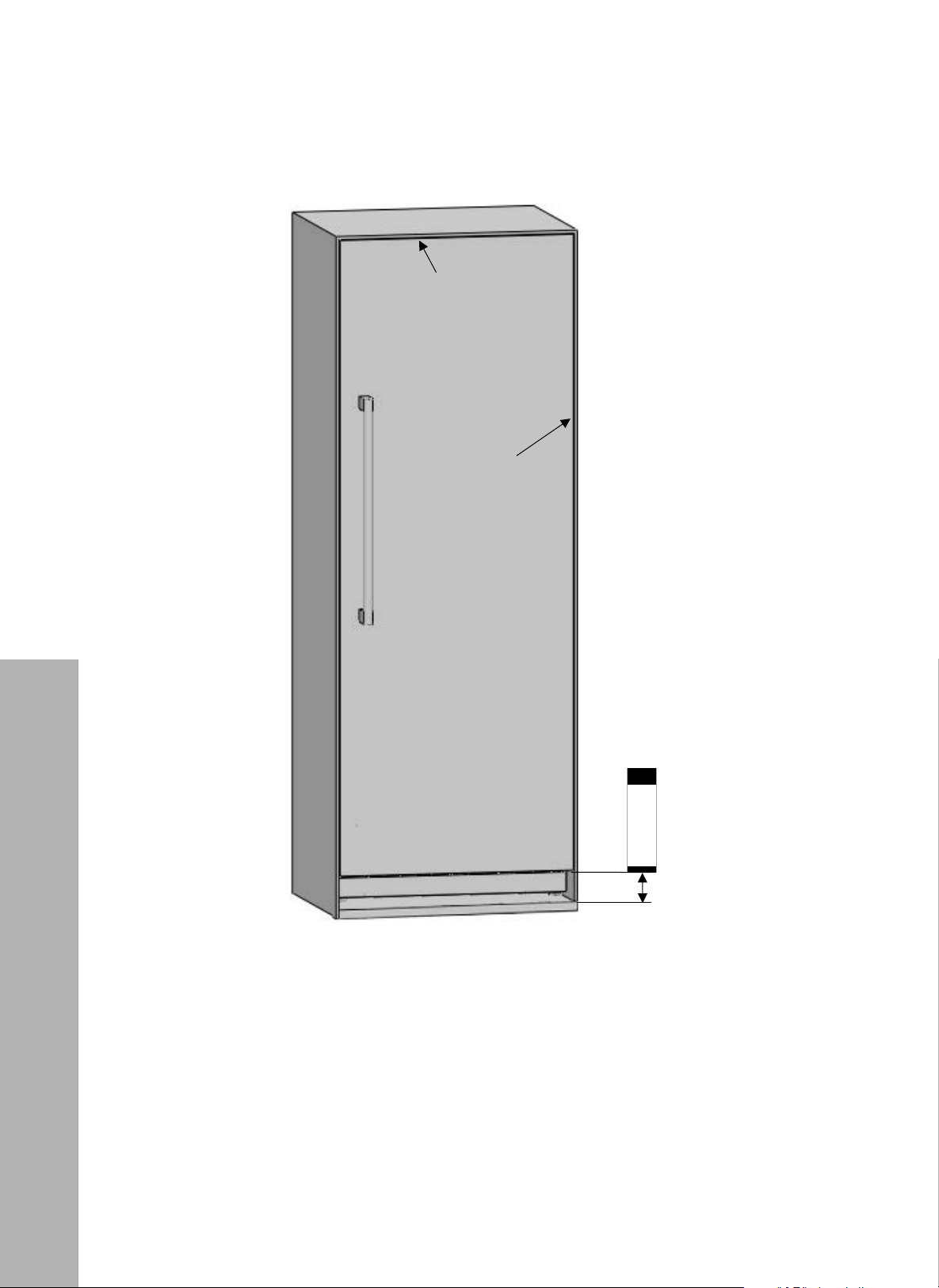
DETAILED DIMENSIONS
!"#$%&'#(%)*! !
!)"
"
!
!
!
!
!
!
!
!
!
!
!
!
!
!
BC)-AD-E,)>3767FF@!
-D-E,)>3FF@!
-D.,)>6FF@
!
.4,)>3-64FF@!
6D4,)>-CFF@!
P$F"HLHL%)=K"Q$)
"R#$')HL=#"::
!
8HLHFJF)I$H%I#) !
";SJ=#F$L#)R&'):$T$:HL%!
2L#H)#HK)<'"Q?$#):&Q"#H&L!
AD63,)
>4FF@!
.4,)>3-64FF@!
.6)3BD63
,)
>3-67FF@!
+'&L#)AD-E,)>.FF@!
P$"') ) -,)>BFF@!
4,)>-7-FF@!
-)3-D63,)
>43FF@!
33)-CD63,)>AB4FF@!
1 5/8" (42 mm)
22 5/8" (574 mm)
4" (102 mm)
84" (2134 mm)
84" (2134 mm)
83 13/16" (2130 mm)
3/16" (4 mm)
Anti-tip bracket location
Minimum height
adjustment for leveling
Front: 5/16" (8 mm)
Rear: 1/4" (7 mm)
79 7/8" (2029 mm)
3/4" (19 mm)
Remaining space after install
1/8" (3 mm)
3/16" (4 mm)
Detailed Dimensions
21
BEFORE INSTALLATION
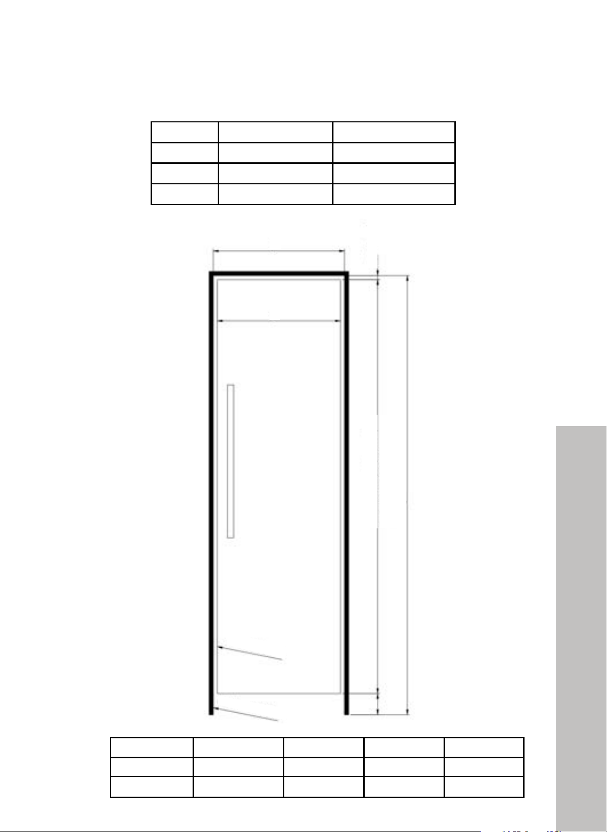
PRODUCT AND CABINET DIMENSIONS
!"#$%&'#(%)*! !
!*"
"
!
!
!
!
!
!
!
!
!
!
!
!
!
!
!
!
!
!
!
!
!
!
!
!
!
!
!
!
!
!
!
!
!
!!!!!!!!!!) U$H%I#)&R)#I$)?H#QI$L)Q&JL#$'#&K)<"=$;)&L)#I$)FHLDF"9V)I$H%I#)&R)#I$)Q"<HLW!
!
!
!
!
!
!
"
"
"
"
"
"
"
!
) 2) /)
=#"L;"';) 4N) >-7-FF@) .4N) >3-64FF@)
FHLHFJF) 6)6D4N>CEFF@) .6)-6D-EX) Y3-3CFFZ)
F"9HFJF) A)6D.XY-6EFFZ) .A)6D.XY3-ECFFZ)
["K\-D.,)>6FF@)
>6FF@!
4,)>-7-FF@!
["K\-D.
,)>6FF@)
>6FF@"
4" (102 mm)
Gap: 1/8" (3 mm)
Gap: 1/8" (3 mm)
Product and Cabinet Dimensions
22
BEFORE INSTALLATION
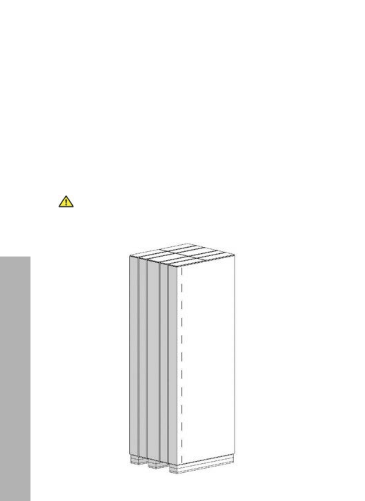
MINIMUM/MAXIMUM HEIGHT OF THE CABINET CUTOUT
A B
Standard 4" (102 mm) 84" (2134 mm)
Minimum 3 3/4" (97 mm) 83 13/16" (2129 mm)
Maximum 5 3/8" (137 mm) 85 3/8" (2169 mm)
!"#$%&'#(%)*! !
#+"
"
!
!
!
!
!
!
!
!
!
!
!
!
!
!
!
!
!
!
!
!
!
!
!
!
!
!
!
!
!
!
!
./012345+ 678!"9:;7:*+ 678	:;7:*+ 6<8	:;7:*+ 6<8,(9:;7:*+
.! !"(!)#$%**+! &#(!)'()**+! &#(!)'()**+!
67,)>BE3FF@!
=+ !%+,-#(!)#$!**+! &,+,-#(!)'(,**+! &,+,-#(!)'(,**+!
0>!,?8@!).4/**+!
Cabinet
Door panel
D
79 15/16" (2030 mm)
Door panel height
1/8" (3 mm)
B
A
C
Category RBCFVL-18/RBCFVR-18 RBCFV-24 RBCRV-24 RBCRV-30
C: Cabinet cutout width 18 3/16" (462 mm) 24 3/16" (614 mm) 24 3/16" (614 mm) 30 3/16" (769 mm)
D: Width of refrigerator 17 3/4" (451 mm) 23 3/4" (603 mm) 23 3/4" (603 mm) 29 3/4" (756 mm)
Product and Cabinet Dimensions
23
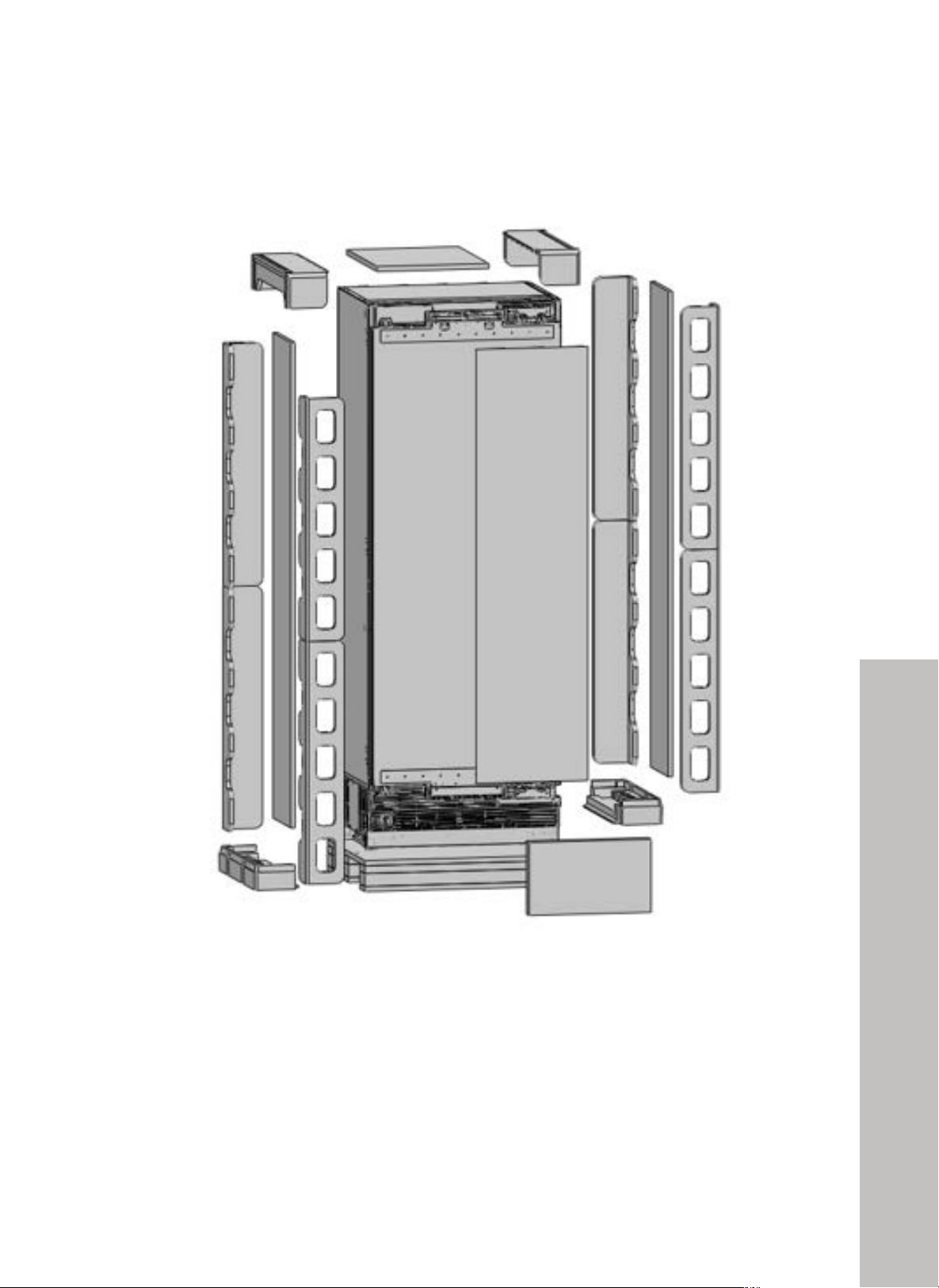
UNPACKING
• Use a box cutter to remove tape on the box packaging.
• Cut the box packaging through the section illustrated in dotted lines in the figure below
and remove it.
• If this refrigerator was purchased with door panels, the panels and handles ship in multiple
boxes and require additional assembly upon installation.
• Please note the diagrams on the following pages will alternate showing the appliance with
and without panels installed; this is done purposefully to show how the item will look panel-
ready versus with panel installed.
• Door panel preparation and installation is covered starting on page 54.
Due to refrigerators and freezers weighing between 243 and 345 pounds
(110 and 156 kilograms), at least two people must move units when
unpacking and installing.
WARNING
BEFORE INSTALLATION
Unpacking
24
REMOVE ALL THE POLYSTYRENE PACKAGING MATERIAL
!"#$%&'#(%)*! !
##"
"
•! D8.0Q8">78"I3@P3;94;"I01-2>-:848".3>8:931<"
+
!
!
! "))*$)%+$'(
Y0"40>":8.0Q8">78">3?8"0K">78"M??8:"500:"04">78"?:05M@>"M4>91">78":8K:9;8:3>0:"92"?13@85"94>0">78"@3/94<" "
D92P"0K">9??94;"0Q8:<"
"
BEFORE INSTALLATION
Unpacking
25
Parts
PARTS PROVIDED
NOTE: THE REFRIGERATOR TRIM PARTS ARE BOXED AND SECURED TO THE REAR OF
THE REFRIGERATOR
Check to ensure all parts are included, then set aside for later.
!"#$%&'#(%)*! !
#$"
"
!
% :.#%F/*2(4-.(6%**.64%0'(%*(4-.(0.)0(B)&&(
"
"
"
"
"
"
"
"
"
"
"
"
"
"
"
"
"
"
"
"
"
"
"
"""""""
""" ! "! !&LR$'$LQ$)
)
"
"
"
"
"
1&) ]"'#)L"F$) ^K$Q) -.) 34) 67)
-) *'HF)RJ'LH#J'$)#&K)
]_!)$9#'J=H&L)5`4AB) -) ) )
]_!)$9#'J=H&L)5`E7C) ) -) )
]_!)$9#'J=H&L)5`BE3) ) ) -)
3) *'HF)RJ'LH#J'$)=H;$)
]_!)$9#'J=H&L)5`-a3AC) 3) 3) 3)
]_!)$9#'J=H&L)5`E-B) 3) 3) 3)
6) *'HF);&&')=H;$) ]_!)$9#'J=H&L)5`-aB.-) 3) 3) 3)
./012345+ 678!"9:;7:*+ 678	:;7:*+ 678	:;7:*+ 6<8,(9:;7:*+
2<<'$TH"#H&L! !"+ &#+ &#+ ,(+
1
2
3
PART NAME SPECIFICATION
QTY
18" 24" 30"
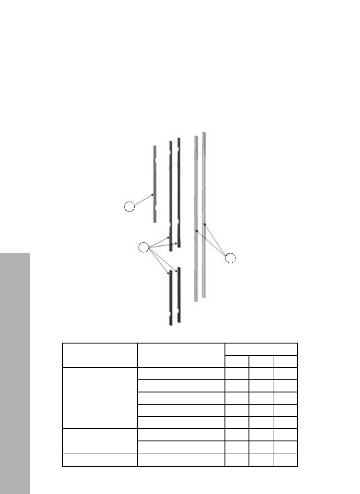
1. Trim cabinet top
18" (457 mm) 1 - -
24" (609 mm) - 1 -
30" (762 mm) - - 1
29 15/16" (761 mm) - - -
35 15/16" (913 mm) 2 2 2
2. Trim cabinet side
49 9/16" (1259 mm) 2 2 2
24 5/16" (617 mm) 2 2 2
3. Trim door side 70 1/8" (1781 mm) 2 2 2
BEFORE INSTALLATION
26
Parts
REMOVE MOUNTING PARTS FROM THE DRAWER COMPARTMENT
• Open the freezer compartment door and remove the packages containing the mounting
parts and check to ensure all parts are included.
27
Parts
BEFORE INSTALLATION
REMOVE MOUNTING PARTS FROM THE DRAWER COMPARTMENT
• Open the freezer compartment door and remove the packages containing the mounting
parts and check to ensure all parts are included.
#%+$#%*$)$&')($)','%#&')#$)
%< '.?A;.:2 *=20 )2:.?8
;A6A6=/?.082A + ?G;0<.A6;4
;A6A6=/?.082A@0?2D@.;11<D29@
$#
'<@6A6<;.17B@A:2;A764 '*
<C2?3B?;6AB?21<<?/?.082A
./@
+?B@@D.@52?52.1 $
?.082A3B?;6AB?21<<?
+ ?G;0<.A6;4
<B;A2?@B;852.1@0?2D *+E
+?B@@D.@52?52.1
$
*>B.?2D.@52? + ?G;0<.A6;4
2;A2?:<B;A6;4/?.082A
+ ?G;0<.A6;4
<B;A2?@B;852.1@0?2D *+E
?.082A3B?;6AB?2 + ?G;0<.A6;4
<B;A2?@B;852.1@0?2D *+$E
+?B@@D.@52?52.1 $
<B;A2?@B;852.1@0?2D *+$E B?;6AB?21<<?5.;42?/?.082A
6?C2;A56;42=.?A * <<?<=2;6;416?20A6<;05.;42
K96:6A=6; L <<?K<=2;6;4B@2
;A6A6=/?.082A@0?2D@
1<D29@
<B;A2?@B;852.1@0?2D
*=20*+$E
6E6;4A520./6;.;1
3B?;6AB?21<<?
D<<1=.?A
+?B@@D.@52?52.1@0?2D
*=20$E
6E6;4)23?642?.A<?
*B05.@0./6;2A.;11<<?
=?2@@=.?A
#%+$#%*$)$&')($)','%#&')#$)
%<
'.?A;.:2
*=20
)2:.?8
;A6A6=/?.082A
+ ?G;0<.A6;4
;A6A6=/?.082A@0?2D@.;11<D29@
$#
'<@6A6<;.17B@A:2;A764
'*
<C2?3B?;6AB?21<<?/?.082A
./@
+?B@@D.@52?52.1
$
?.082A3B?;6AB?21<<?
+ ?G;0<.A6;4
<B;A2?@B;852.1@0?2D
*+E
+?B@@D.@52?52.1
$
*>B.?2D.@52?
+ ?G;0<.A6;4
2;A2?:<B;A6;4/?.082A
+ ?G;0<.A6;4
<B;A2?@B;852.1@0?2D
*+E
?.082A3B?;6AB?2
+ ?G;0<.A6;4
<B;A2?@B;852.1@0?2D
*+$E
+?B@@D.@52?52.1
$
<B;A2?@B;852.1@0?2D
*+$E
B?;6AB?21<<?5.;42?/?.082A
6?C2;A56;42=.?A
*
<<?<=2;6;416?20A6<;05.;42
K96:6A=6;
L
<<?K<=2;6;4B@2
;A6A6=/?.082A@0?2D@
1<D29@
<B;A2?@B;852.1@0?2D
*=20*+$E
6E6;4A520./6;.;1
3B?;6AB?21<<?
D<<1=.?A
+?B@@D.@52?52.1@0?2D
*=20$E
6E6;4)23?642?.A<?
*B05.@0./6;2A.;11<<?
=?2@@=.?A
20
#%+$#%*$)$&')($)','%#&')#$)
%<
'.?A;.:2
*=20
)2:.?8
;A6A6=/?.082A
+ ?G;0<.A6;4
;A6A6=/?.082A@0?2D@.;11<D29@
$#
'<@6A6<;.17B@A:2;A764
'*
<C2?3B?;6AB?21<<?/?.082A
./@
+?B@@D.@52?52.1
$
?.082A3B?;6AB?21<<?
+ ?G;0<.A6;4
<B;A2?@B;852.1@0?2D
*+E
+?B@@D.@52?52.1
$
*>B.?2D.@52?
+ ?G;0<.A6;4
2;A2?:<B;A6;4/?.082A
+ ?G;0<.A6;4
<B;A2?@B;852.1@0?2D
*+E
?.082A3B?;6AB?2
+ ?G;0<.A6;4
<B;A2?@B;852.1@0?2D
*+$E
+?B@@D.@52?52.1
$
<B;A2?@B;852.1@0?2D
*+$E
B?;6AB?21<<?5.;42?/?.082A
6?C2;A56;42=.?A
*
<<?<=2;6;416?20A6<;05.;42
K96:6A=6;
L
<<?K<=2;6;4B@2
;A6A6=/?.082A@0?2D@
1<D29@
<B;A2?@B;852.1@0?2D
*=20*+$E
6E6;4A520./6;.;1
3B?;6AB?21<<?
D<<1=.?A
+?B@@D.@52?52.1@0?2D
*=20$E
6E6;4)23?642?.A<?
*B05.@0./6;2A.;11<<?
=?2@@=.?A
21
1
2 3
4
5
6
7
8
9
10
11
12
13
14
15
16
17
Confident ial
29
Open t he freezer com partm ent door a nd rem ove the m ounting boxes and docum ents in the
cris per.
√
Conference
No Part name spec 76 91 92
1 Furniture door preparation template paper 1 1 1
2 Anti tip bracket T4. 0, Zn- coating 2 2 2
3 Dowel - 8 8 8
4 Anti tip bracket screws M8*L60 8 8 8
5 Position adjustment jig PS 1 1 1
6 90° limiti ng pins sus 2 2 -
7 Freezer furniture door adjustment washer abs 9 9 9
8 Screw freezer door hanger bracket ST4. 8*16, round head screw 3 3 3
9 Freezer door hanger bracket T1. 0, Cr+zn- coating 3 3 3
10
Screw freezer furniture door
hanger bracket
ST4x14, counter sunk head
screw 18 18 18
11 Screw cabinet connecting bracket M4*12, truss washer head 16 16 16
Category TRF- 76BINFIA TRF- 91BINFIA TRF- 92BINFIA
Abbreviation. 76 91 92
1 2 3 4 5 6
8
7
9
10
14
15
18
16
17
11
12
13
#%+$#%*$)$&')($)','%#&')#$)
%<
'.?A;.:2
*=20
)2:.?8
;A6A6=/?.082A
+ ?G;0<.A6;4
;A6A6=/?.082A@0?2D@.;11<D29@
$#
'<@6A6<;.17B@A:2;A764
'*
<C2?3B?;6AB?21<<?/?.082A
./@
+?B@@D.@52?52.1
$
?.082A3B?;6AB?21<<?
+ ?G;0<.A6;4
<B;A2?@B;852.1@0?2D
*+E
+?B@@D.@52?52.1
$
*>B.?2D.@52?
+ ?G;0<.A6;4
2;A2?:<B;A6;4/?.082A
+ ?G;0<.A6;4
<B;A2?@B;852.1@0?2D
*+E
?.082A3B?;6AB?2
+ ?G;0<.A6;4
<B;A2?@B;852.1@0?2D
*+$E
+?B@@D.@52?52.1
$
<B;A2?@B;852.1@0?2D
*+$E
B?;6AB?21<<?5.;42?/?.082A
6?C2;A56;42=.?A
*
<<?<=2;6;416?20A6<;05.;42
K96:6A=6;
L
<<?K<=2;6;4B@2
;A6A6=/?.082A@0?2D@
1<D29@
<B;A2?@B;852.1@0?2D
*=20*+$E
6E6;4A520./6;.;1
3B?;6AB?21<<?
D<<1=.?A
+?B@@D.@52?52.1@0?2D
*=20$E
6E6;4)23?642?.A<?
*B05.@0./6;2A.;11<<?
=?2@@=.?A
18
#%+$#%*$)$&')($)','%#&')#$)
%<
'.?A;.:2
*=20
)2:.?8
;A6A6=/?.082A
+ ?G;0<.A6;4
;A6A6=/?.082A@0?2D@.;11<D29@
$#
'<@6A6<;.17B@A:2;A764
'*
<C2?3B?;6AB?21<<?/?.082A
./@
+?B@@D.@52?52.1
$
?.082A3B?;6AB?21<<?
+ ?G;0<.A6;4
<B;A2?@B;852.1@0?2D
*+E
+?B@@D.@52?52.1
$
*>B.?2D.@52?
+ ?G;0<.A6;4
2;A2?:<B;A6;4/?.082A
+ ?G;0<.A6;4
<B;A2?@B;852.1@0?2D
*+E
?.082A3B?;6AB?2
+ ?G;0<.A6;4
<B;A2?@B;852.1@0?2D
*+$E
+?B@@D.@52?52.1
$
<B;A2?@B;852.1@0?2D
*+$E
B?;6AB?21<<?5.;42?/?.082A
6?C2;A56;42=.?A
*
<<?<=2;6;416?20A6<;05.;42
K96:6A=6;
L
<<?K<=2;6;4B@2
;A6A6=/?.082A@0?2D@
1<D29@
<B;A2?@B;852.1@0?2D
*=20*+$E
6E6;4A520./6;.;1
3B?;6AB?21<<?
D<<1=.?A
+?B@@D.@52?52.1@0?2D
*=20$E
6E6;4)23?642?.A<?
*B05.@0./6;2A.;11<<?
=?2@@=.?A
19
PART NAME SPECIFICATION IMAGE
QTY
18 " 24" 30"
12 . Cabinet mounting bracket - - 8 8 8
13 . Screws to secure cabinet mounting brackets
to cabinet cutout
ST M4 x 14 mm
16 16 16
14 . Screw cabinet connecting bracket
M4 x 12 mm, crossed
flat head tapping screws
16 16 16
15 . Counter sunk head screw ST M4 x 14 mm
16 20 20
16. Air vent hinge - - - 1 1
17. 90° limiting pins - - 2 2 2
18 . Door panel preparation template - - 1 1 1
19. Water filter bypass plug (if needed) - - 1 1 1
20. Hinge bracket (left hinge)*
*Refrigerator will have 2 brackets marked with letter “L”
- - - 2 2
21. Hinge bracket (right hinge)*
*Freezer will have 2 brackets marked with letter “R”
- - - 2 2
Column Refrigerator - Installation Manual - English - USA - November 2024 - PRINT.indd 27 ɐ30
BEFORE INSTALLATION
PART NAME SPECIFICATION IMAGE
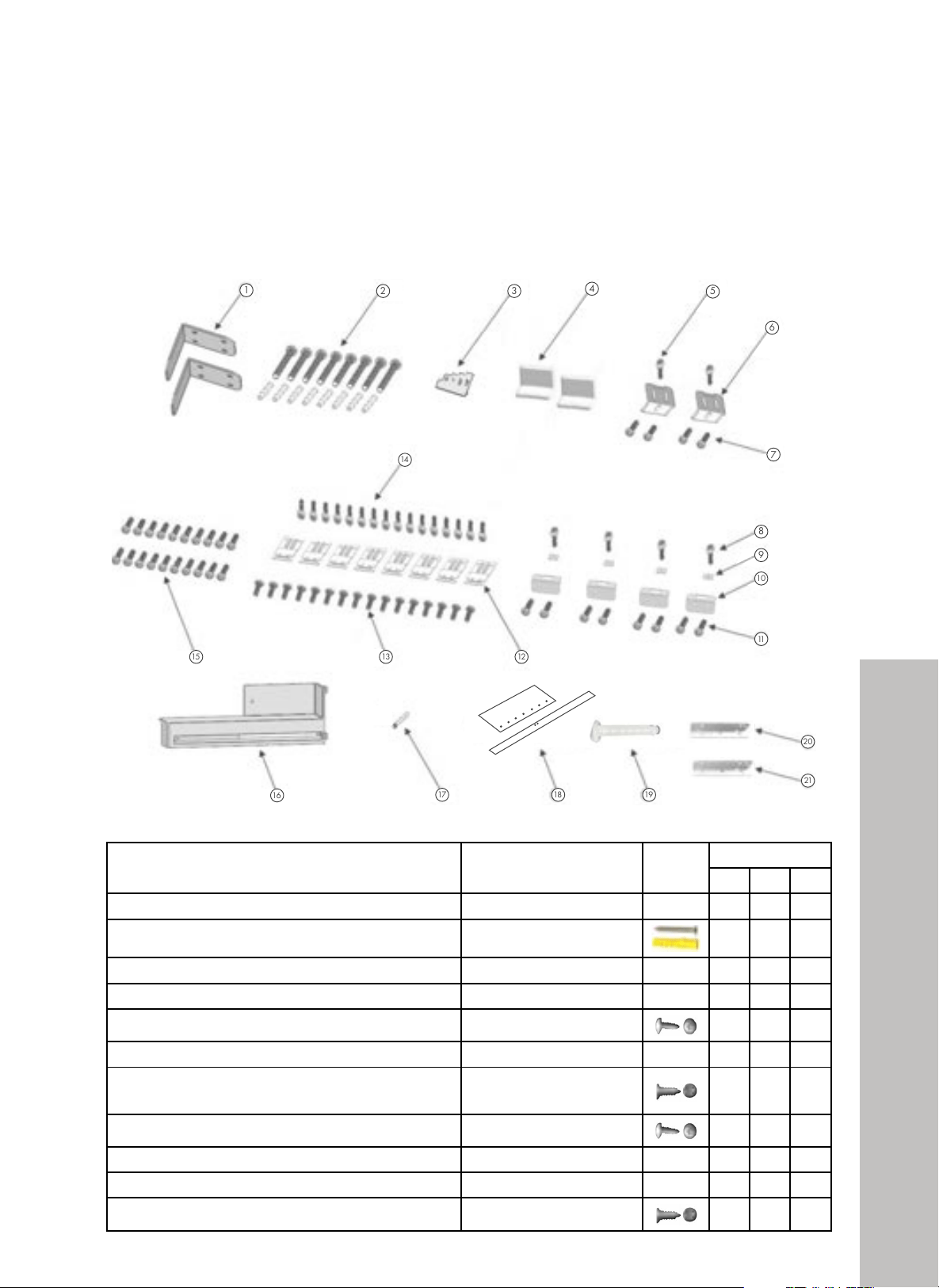
QTY
18" 24" 30"
1. Anti-tip bracket - - 8 8 8
2. Anti tip bracket screws and anchors -
Confidential
30
R em ove it m an ually wit h 4 knurled s crews .
R em ove th e L ower Cris per.
No Part name spec 76 91 92
12 Cabinet- cabin connecting bracket T1. 0, Zn- coating 8 8 8
13 Screw cabin connecting bracket ST4x14, counter sunk head screw 16 16 16
14 Cover furniture door bracket abs 4 4 2
15 Screw door fix ing bracket M4*12, truss washer head 4 4 2
16 Door- door furniture connecting bracket T1. 0, Cr+zn- coating 4 4 2
17 Screw furniture door fixing bracket ST4x14, counter sunk head screw 8 8 4
18 Screw
furniture door hanger bracket ST4x14, counter sunk head screw 20 20 24
Anti tip bracket screws
dowels
Truss washer head screw
Spec : M4x12
Fixi ng Refrigerator
Such as cabinet and door
(press part)
Counter sunk head screw
Spec : ST4x14
Fixi ng the cabin and
furniture door
(wood part)
Round head screw
Spec : ST 4. 8x16
Fixi ng freezer door top part
and furniture door
(press part)
8 8 8
3. Position adjustment gauge - - 1 1 1
4. Door panel connecting bracket - - - 2 2
5. Truss washer head M4 x12 mm
- 2 2
6. Door panel connecting bracket - - - 2 2
7. Screws to secure door panel connecting
bracket to panel
ST4 x14 mm
- 4 4
8. Crossed flat head tapping screws M4 x12 mm
4 4 4
9. Washer for panel side mounting bracket - - 4 4 4
10. Panel side mounting bracket - - 4 4 4
11 . Screws to secure panel side mounting bracket M4 x 12 mm
8 8 8
27
Parts
BEFORE INSTALLATION
PART NAME SPECIFICATION IMAGE
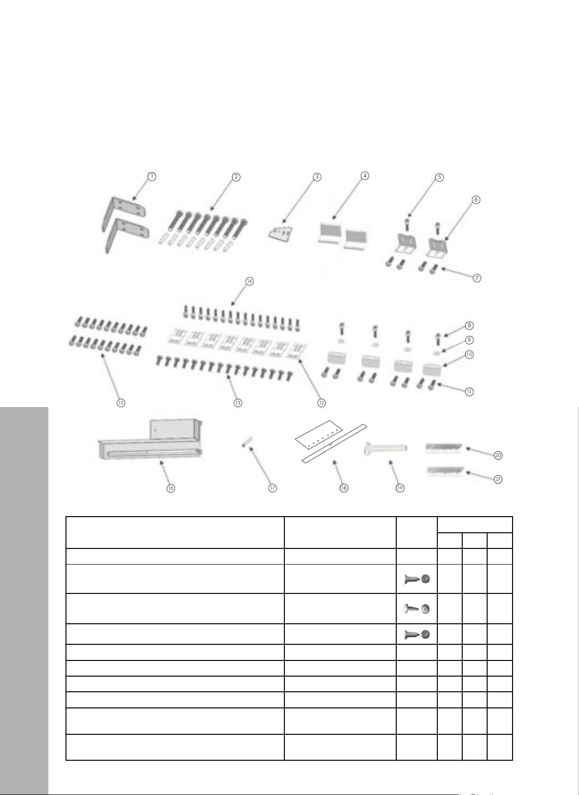
QTY
18" 24" 30"
12. Cabinet mounting bracket - - 8 8 8
13. Screws to secure cabinet mounting brackets
to cabinet cutout
ST M4 x 14 mm
16 16 16
14. Screw cabinet connecting bracket
M4 x 12 mm, crossed
flat head tapping screws
16 16 16
15. Counter sunk head screw ST M4 x 14 mm
16 20 20
16. Air vent hinge - - - 1 1
17. 90° limiting pins - - 1 1 1
18. Door panel preparation template - - 1 1 1
19. Water filter bypass plug (if needed) - - 1 1 1
20. Hinge bracket (left hinge)*
*Refrigerator will have 2 brackets marked with letter “L”
- - - 2 2
21. Hinge bracket (right hinge)*
*Freezer will have 2 brackets marked with letter “R”
- - - 2 2
REMOVE MOUNTING PARTS FROM THE DRAWER COMPARTMENT
• Open the freezer compartment door and remove the packages containing the mounting
parts and check to ensure all parts are included.
27
Parts
BEFORE INSTALLATION
REMOVE MOUNTING PARTS FROM THE DRAWER COMPARTMENT
• Open the freezer compartment door and remove the packages containing the mounting
parts and check to ensure all parts are included.
#%+$#%*$)$&')($)','%#&')#$)
%< '.?A;.:2 *=20 )2:.?8
;A6A6=/?.082A + ?G;0<.A6;4
;A6A6=/?.082A@0?2D@.;11<D29@
$#
'<@6A6<;.17B@A:2;A764 '*
<C2?3B?;6AB?21<<?/?.082A
./@
+?B@@D.@52?52.1 $
?.082A3B?;6AB?21<<?
+ ?G;0<.A6;4
<B;A2?@B;852.1@0?2D *+E
+?B@@D.@52?52.1
$
*>B.?2D.@52? + ?G;0<.A6;4
2;A2?:<B;A6;4/?.082A
+ ?G;0<.A6;4
<B;A2?@B;852.1@0?2D *+E
?.082A3B?;6AB?2 + ?G;0<.A6;4
<B;A2?@B;852.1@0?2D *+$E
+?B@@D.@52?52.1 $
<B;A2?@B;852.1@0?2D *+$E B?;6AB?21<<?5.;42?/?.082A
6?C2;A56;42=.?A * <<?<=2;6;416?20A6<;05.;42
K96:6A=6; L <<?K<=2;6;4B@2
;A6A6=/?.082A@0?2D@
1<D29@
<B;A2?@B;852.1@0?2D
*=20*+$E
6E6;4A520./6;.;1
3B?;6AB?21<<?
D<<1=.?A
+?B@@D.@52?52.1@0?2D
*=20$E
6E6;4)23?642?.A<?
*B05.@0./6;2A.;11<<?
=?2@@=.?A
#%+$#%*$)$&')($)','%#&')#$)
%<
'.?A;.:2
*=20
)2:.?8
;A6A6=/?.082A
+ ?G;0<.A6;4
;A6A6=/?.082A@0?2D@.;11<D29@
$#
'<@6A6<;.17B@A:2;A764
'*
<C2?3B?;6AB?21<<?/?.082A
./@
+?B@@D.@52?52.1
$
?.082A3B?;6AB?21<<?
+ ?G;0<.A6;4
<B;A2?@B;852.1@0?2D
*+E
+?B@@D.@52?52.1
$
*>B.?2D.@52?
+ ?G;0<.A6;4
2;A2?:<B;A6;4/?.082A
+ ?G;0<.A6;4
<B;A2?@B;852.1@0?2D
*+E
?.082A3B?;6AB?2
+ ?G;0<.A6;4
<B;A2?@B;852.1@0?2D
*+$E
+?B@@D.@52?52.1
$
<B;A2?@B;852.1@0?2D
*+$E
B?;6AB?21<<?5.;42?/?.082A
6?C2;A56;42=.?A
*
<<?<=2;6;416?20A6<;05.;42
K96:6A=6;
L
<<?K<=2;6;4B@2
;A6A6=/?.082A@0?2D@
1<D29@
<B;A2?@B;852.1@0?2D
*=20*+$E
6E6;4A520./6;.;1
3B?;6AB?21<<?
D<<1=.?A
+?B@@D.@52?52.1@0?2D
*=20$E
6E6;4)23?642?.A<?
*B05.@0./6;2A.;11<<?
=?2@@=.?A
20
#%+$#%*$)$&')($)','%#&')#$)
%<
'.?A;.:2
*=20
)2:.?8
;A6A6=/?.082A
+ ?G;0<.A6;4
;A6A6=/?.082A@0?2D@.;11<D29@
$#
'<@6A6<;.17B@A:2;A764
'*
<C2?3B?;6AB?21<<?/?.082A
./@
+?B@@D.@52?52.1
$
?.082A3B?;6AB?21<<?
+ ?G;0<.A6;4
<B;A2?@B;852.1@0?2D
*+E
+?B@@D.@52?52.1
$
*>B.?2D.@52?
+ ?G;0<.A6;4
2;A2?:<B;A6;4/?.082A
+ ?G;0<.A6;4
<B;A2?@B;852.1@0?2D
*+E
?.082A3B?;6AB?2
+ ?G;0<.A6;4
<B;A2?@B;852.1@0?2D
*+$E
+?B@@D.@52?52.1
$
<B;A2?@B;852.1@0?2D
*+$E
B?;6AB?21<<?5.;42?/?.082A
6?C2;A56;42=.?A
*
<<?<=2;6;416?20A6<;05.;42
K96:6A=6;
L
<<?K<=2;6;4B@2
;A6A6=/?.082A@0?2D@
1<D29@
<B;A2?@B;852.1@0?2D
*=20*+$E
6E6;4A520./6;.;1
3B?;6AB?21<<?
D<<1=.?A
+?B@@D.@52?52.1@0?2D
*=20$E
6E6;4)23?642?.A<?
*B05.@0./6;2A.;11<<?
=?2@@=.?A
21
1
2 3
4
5
6
7
8
9
10
11
12
13
14
15
16
17
Confident ial
29
Open t he freezer com partm ent door a nd rem ove the m ounting boxes and docum ents in the
cris per.
√
Conference
No Part name spec 76 91 92
1 Furniture door preparation template paper 1 1 1
2 Anti tip bracket T4. 0, Zn- coating 2 2 2
3 Dowel - 8 8 8
4 Anti tip bracket screws M8*L60 8 8 8
5 Position adjustment jig PS 1 1 1
6 90° limiti ng pins sus 2 2 -
7 Freezer furniture door adjustment washer abs 9 9 9
8 Screw freezer door hanger bracket ST4. 8*16, round head screw 3 3 3
9 Freezer door hanger bracket T1. 0, Cr+zn- coating 3 3 3
10
Screw freezer furniture door
hanger bracket
ST4x14, counter sunk head
screw 18 18 18
11 Screw cabinet connecting bracket M4*12, truss washer head 16 16 16
Category TRF- 76BINFIA TRF- 91BINFIA TRF- 92BINFIA
Abbreviation. 76 91 92
1 2 3 4 5 6
8
7
9
10
14
15
18
16
17
11
12
13
#%+$#%*$)$&')($)','%#&')#$)
%<
'.?A;.:2
*=20
)2:.?8
;A6A6=/?.082A
+ ?G;0<.A6;4
;A6A6=/?.082A@0?2D@.;11<D29@
$#
'<@6A6<;.17B@A:2;A764
'*
<C2?3B?;6AB?21<<?/?.082A
./@
+?B@@D.@52?52.1
$
?.082A3B?;6AB?21<<?
+ ?G;0<.A6;4
<B;A2?@B;852.1@0?2D
*+E
+?B@@D.@52?52.1
$
*>B.?2D.@52?
+ ?G;0<.A6;4
2;A2?:<B;A6;4/?.082A
+ ?G;0<.A6;4
<B;A2?@B;852.1@0?2D
*+E
?.082A3B?;6AB?2
+ ?G;0<.A6;4
<B;A2?@B;852.1@0?2D
*+$E
+?B@@D.@52?52.1
$
<B;A2?@B;852.1@0?2D
*+$E
B?;6AB?21<<?5.;42?/?.082A
6?C2;A56;42=.?A
*
<<?<=2;6;416?20A6<;05.;42
K96:6A=6;
L
<<?K<=2;6;4B@2
;A6A6=/?.082A@0?2D@
1<D29@
<B;A2?@B;852.1@0?2D
*=20*+$E
6E6;4A520./6;.;1
3B?;6AB?21<<?
D<<1=.?A
+?B@@D.@52?52.1@0?2D
*=20$E
6E6;4)23?642?.A<?
*B05.@0./6;2A.;11<<?
=?2@@=.?A
18
#%+$#%*$)$&')($)','%#&')#$)
%<
'.?A;.:2
*=20
)2:.?8
;A6A6=/?.082A
+ ?G;0<.A6;4
;A6A6=/?.082A@0?2D@.;11<D29@
$#
'<@6A6<;.17B@A:2;A764
'*
<C2?3B?;6AB?21<<?/?.082A
./@
+?B@@D.@52?52.1
$
?.082A3B?;6AB?21<<?
+ ?G;0<.A6;4
<B;A2?@B;852.1@0?2D
*+E
+?B@@D.@52?52.1
$
*>B.?2D.@52?
+ ?G;0<.A6;4
2;A2?:<B;A6;4/?.082A
+ ?G;0<.A6;4
<B;A2?@B;852.1@0?2D
*+E
?.082A3B?;6AB?2
+ ?G;0<.A6;4
<B;A2?@B;852.1@0?2D
*+$E
+?B@@D.@52?52.1
$
<B;A2?@B;852.1@0?2D
*+$E
B?;6AB?21<<?5.;42?/?.082A
6?C2;A56;42=.?A
*
<<?<=2;6;416?20A6<;05.;42
K96:6A=6;
L
<<?K<=2;6;4B@2
;A6A6=/?.082A@0?2D@
1<D29@
<B;A2?@B;852.1@0?2D
*=20*+$E
6E6;4A520./6;.;1
3B?;6AB?21<<?
D<<1=.?A
+?B@@D.@52?52.1@0?2D
*=20$E
6E6;4)23?642?.A<?
*B05.@0./6;2A.;11<<?
=?2@@=.?A
19
PART NAME SPECIFICATION IMAGE
QTY
18 " 24" 30"
12 . Cabinet mounting bracket - - 8 8 8
13 . Screws to secure cabinet mounting brackets
to cabinet cutout
ST M4 x 14 mm
16 16 16
14 . Screw cabinet connecting bracket
M4 x 12 mm, crossed
flat head tapping screws
16 16 16
15 . Counter sunk head screw ST M4 x 14 mm
16 20 20
16. Air vent hinge - - - 1 1
17. 90° limiting pins - - 2 2 2
18 . Door panel preparation template - - 1 1 1
19. Water filter bypass plug (if needed) - - 1 1 1
20. Hinge bracket (left hinge)*
*Refrigerator will have 2 brackets marked with letter “L”
- - - 2 2
21. Hinge bracket (right hinge)*
*Freezer will have 2 brackets marked with letter “R”
- - - 2 2
Column Refrigerator - Installation Manual - English - USA - November 2024 - PRINT.indd 27 ɐ30
28
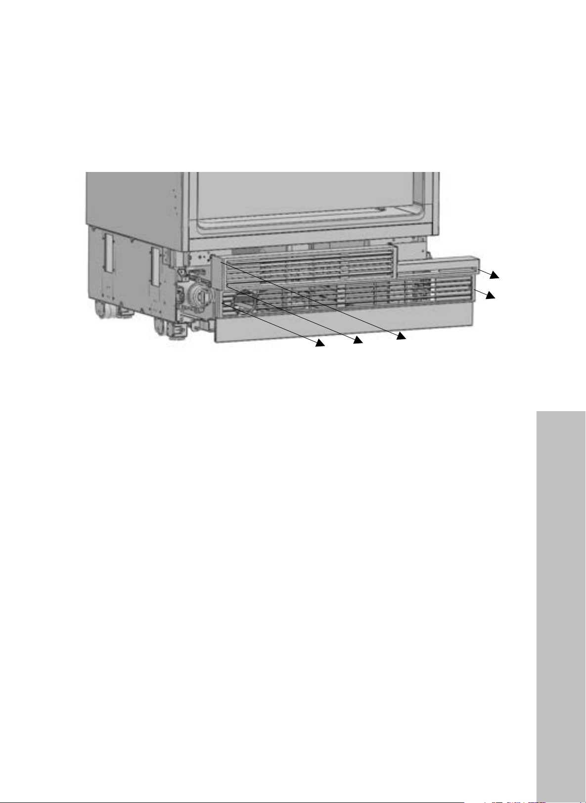
REMOVING THE VENT HOLE ASSEMBLY
Remove the five screws to take out the vent assembly; set the screws aside.
"
#&"
"
:.#%F/*2(4-.(F.*4(-%&.()''.#$&"(
•! D8.0Q8"&"2@:8L2">0">3P8"0M>">78"F84>"T018""A228./1-<"
+
+
!
!
!
!
+
"
"
"
"
"
"
"
"
!"#$%&'#(%)*! !
#%"
"
:.#%F/*2(#%C*4/*2(5)04'(/*(4-.(+0)B.0(6%#5)04#.*4(
%
"
"
"
"
"
"
"
"
"
"
"
"
+
!
!
!
!
!
!
!
!
!
!
!
!
!
!
!
!
!
!
!
!
!
!
!
!
1&)
]"'#)L"F$)
^K$Q)
-.)
34)
67)
P$F"'?)
-)
2L#H,#HK)<'"Q?$#)
*4V7a) ) !'bcL,Q&"#HL%)
.)
.)
.)
)
3)
2L#H)#HK)<'"Q?$#)=Q'$G=)"L;);&G$:=)
8.d5E7)
.)
.)
.)
)
6)
]&=H#H&L)";SJ=#F$L#)SH%)
]^)
-)
-)
-)
)
4)
!&T$')RJ'LH#J'$);&&')<'"Q?$#)
"<=)
,)
3)
3)
)
A)
*'J==)G"=I$')I$";)
84d-3)
,)
3)
3)
)
E)
/'"Q?$#)RJ'LH#J'$);&&')
*-V7a) ) !'bcL,Q&"#HL%)
,)
3)
3)
)
B)
!&JL#$')=JL?)I$";)=Q'$G)
^*49-4)
,)
4)
4)
)
.)
*'J==)G"=I$')I$";)
84d-3)
4)
4)
4)
)
C)
^eJ"'$)G"=I$')
*-V7a) ) !'bcL,Q&"#HL%)
4)
4)
4)
)
-7)
!$L#$')F&JL#HL%)<'"Q?$#)
*-V7a) ) !'bcL,Q&"#HL%)
4)
4)
4)
)
--)
!&JL#$')=JL?)I$";)=Q'$G)
^*49-4)
.)
.)
.)
)
-3)
/'"Q?$#)RJ'LH#J'$) )
*-V7a) ) !'bcL,Q&"#HL%)
.)
.)
.)
)
-6)
!&JL#$')=JL?)I$";)=Q'$G)
^*)849-4)
-E)
-E)
-E)
)
-4)
*'J==)G"=I$')I$";)
84d-3)
-E)
-E)
-E)
)
-A)
!&JL#$')=JL?)I$";)=Q'$G)))
^*)849-4)
-E)
37)
37)
+J'LH#J'$);&&')I"L%$')<'"Q?$#)
-E)
2H')T$L#)IHL%$)K"'#)
2/^)
,)
-)
-)
O&&')&K$LHL%);H'$Q#H&L)QI"L%$)
-B)
C7f:HFH#)KHL)
g4)
3)
3)
3)
O&&')C7f&K$LHL%)J=$)
!! 2L#H)#HK)<'"Q?$#)=Q'$G=) )
!! ;&G$:="
!! !&JL#$')=JL?)I$";)=Q'$G)
^K$Q)M)^*)849-4)
+H9HL%)#I$)Q"<HL)"L;)
RJ'LH#J'$);&&')
>G&&;)K"'#@)
!! *'J==)G"=I$')I$";)=Q'$G"
^K$Q)M)849-3)
+H9HL%)P$R'H%$'"#&')
^JQI)"=)Q"<HL$#)"L;);&&')
>K'$==)K"'#@)
!"#$%&'#(%)*! !
#%"
"
:.#%F/*2(#%C*4/*2(5)04'(/*(4-.(+0)B.0(6%#5)04#.*4(
%
"
"
"
"
"
"
"
"
"
"
"
"
+
!
!
!
!
!
!
!
!
!
!
!
!
!
!
!
!
!
!
!
!
!
!
!
!
1&)
]"'#)L"F$)
^K$Q)
-.)
34)
67)
P$F"'?)
-)
2L#H,#HK)<'"Q?$#)
*4V7a) ) !'bcL,Q&"#HL%)
.)
.)
.)
)
3)
2L#H)#HK)<'"Q?$#)=Q'$G=)"L;);&G$:=)
8.d5E7)
.)
.)
.)
)
6)
]&=H#H&L)";SJ=#F$L#)SH%)
]^)
-)
-)
-)
)
4)
!&T$')RJ'LH#J'$);&&')<'"Q?$#)
"<=)
,)
3)
3)
)
A)
*'J==)G"=I$')I$";)
84d-3)
,)
3)
3)
)
E)
/'"Q?$#)RJ'LH#J'$);&&')
*-V7a) ) !'bcL,Q&"#HL%)
,)
3)
3)
)
B)
!&JL#$')=JL?)I$";)=Q'$G)
^*49-4)
,)
4)
4)
)
.)
*'J==)G"=I$')I$";)
84d-3)
4)
4)
4)
)
C)
^eJ"'$)G"=I$')
*-V7a) ) !'bcL,Q&"#HL%)
4)
4)
4)
)
-7)
!$L#$')F&JL#HL%)<'"Q?$#)
*-V7a) ) !'bcL,Q&"#HL%)
4)
4)
4)
)
--)
!&JL#$')=JL?)I$";)=Q'$G)
^*49-4)
.)
.)
.)
)
-3)
/'"Q?$#)RJ'LH#J'$) )
*-V7a) ) !'bcL,Q&"#HL%)
.)
.)
.)
)
-6)
!&JL#$')=JL?)I$";)=Q'$G)
^*)849-4)
-E)
-E)
-E)
)
-4)
*'J==)G"=I$')I$";)
84d-3)
-E)
-E)
-E)
)
-A)
!&JL#$')=JL?)I$";)=Q'$G)))
^*)849-4)
-E)
37)
37)
+J'LH#J'$);&&')I"L%$')<'"Q?$#)
-E)
2H')T$L#)IHL%$)K"'#)
2/^)
,)
-)
-)
O&&')&K$LHL%);H'$Q#H&L)QI"L%$)
-B)
C7f:HFH#)KHL)
g4)
3)
3)
3)
O&&')C7f&K$LHL%)J=$)
!! 2L#H)#HK)<'"Q?$#)=Q'$G=) )
!! ;&G$:="
!! !&JL#$')=JL?)I$";)=Q'$G)
^K$Q)M)^*)849-4)
+H9HL%)#I$)Q"<HL)"L;)
RJ'LH#J'$);&&')
>G&&;)K"'#@)
!! *'J==)G"=I$')I$";)=Q'$G"
^K$Q)M)849-3)
+H9HL%)P$R'H%$'"#&')
^JQI)"=)Q"<HL$#)"L;);&&')
>K'$==)K"'#@)
Confident ial
29
Open the freezer com part m ent door and rem ove the m ounting boxes and docum ents in the
cris per.
√ Conference
No Part name spec 76 91 92
1 Furniture door preparation template paper 1 1 1
2 Anti tip bracket T4. 0, Zn- coating 2 2 2
3 Dowel - 8 8 8
4 Anti tip bracket screws M8*L60 8 8 8
5 Position adjustment jig PS 1 1 1
6 90° limiting pins sus 2 2 -
7 Freezer furniture door adjustment washer abs 9 9 9
8 S crew freezer door hanger bracket ST4. 8*16, round head screw 3 3 3
9 Freezer door hanger bracket T1. 0, Cr+zn- coating 3 3 3
10
Screw freezer furniture door
hanger bracket
ST4x14, counter sunk head
screw
18 18 18
11 Screw cabi net connecting bracket M4*12, truss washer head 16 16 16
Category TRF- 76BINFIA TRF- 91BINFIA TRF- 92BINFIA
Abbreviation. 76 91 92
1 2 3 4 5 6
8
7
9
10
14
15
18
16
17
11
12
13
!"#$%&'#(%)*! !
#%"
"
:.#%F/*2(#%C*4/*2(5)04'(/*(4-.(+0)B.0(6%#5)04#.*4(
%
"
"
"
"
"
"
"
"
"
"
"
"
+
!
!
!
!
!
!
!
!
!
!
!
!
!
!
!
!
!
!
!
!
!
!
!
!
1&)
]"'#)L"F$) ^K$Q) -.) 34) 67) P$F"'?)
-)
2L#H,#HK)<'"Q?$#) *4V7a) ) !'bcL,Q&"#HL%) .) .) .) )
3)
2L#H)#HK)<'"Q?$#)=Q'$G=)"L;);&G$:=) 8.d5E7) .) .) .) )
6)
]&=H#H&L)";SJ=#F$L#)SH%) ]^) -) -) -) )
4)
!&T$')RJ'LH#J'$);&&')<'"Q?$#) "<=) ,) 3) 3) )
A)
*'J==)G"=I$')I$";) 84d-3) ,) 3) 3) )
E)
/'"Q?$#)RJ'LH#J'$);&&') *-V7a) ) !'bcL,Q&"#HL%) ,) 3) 3) )
B)
!&JL#$')=JL?)I$";)=Q'$G) ^*49-4) ,) 4) 4) )
.)
*'J==)G"=I$')I$";) 84d-3) 4) 4) 4) )
C)
^eJ"'$)G"=I$') *-V7a) ) !'bcL,Q&"#HL%) 4) 4) 4) )
-7)
!$L#$')F&JL#HL%)<'"Q?$#) *-V7a) ) !'bcL,Q&"#HL%) 4) 4) 4) )
--)
!&JL#$')=JL?)I$";)=Q'$G) ^*49-4) .) .) .) )
-3)
/'"Q?$#)RJ'LH#J'$) ) *-V7a) ) !'bcL,Q&"#HL%) .) .) .) )
-6)
!&JL#$')=JL?)I$";)=Q'$G) ^*)849-4) -E) -E) -E) )
-4)
*'J==)G"=I$')I$";) 84d-3) -E) -E) -E) )
-A)
!&JL#$')=JL?)I$";)=Q'$G))) ^*)849-4) -E) 37) 37) +J'LH#J'$);&&')I"L%$')<'"Q?$#)
-E)
2H')T$L#)IHL%$)K"'#) 2/^) ,) -) -) O&&')&K$LHL%);H'$Q#H&L)QI"L%$)
-B)
C7f:HFH#)KHL) g4) 3) 3) 3) O&&')C7f&K$LHL%)J=$)
!! 2L#H)#HK)<'"Q?$#)=Q'$G=) )
!! ;&G$:="
!! !&JL#$')=JL?)I$";)=Q'$G)
^K$Q)M)^*)849-4)
+H9HL%)#I$)Q"<HL)"L;)
RJ'LH#J'$);&&')
>G&&;)K"'#@)
!! *'J==)G"=I$')I$";)=Q'$G"
^K$Q)M)849-3)
+H9HL%)P$R'H%$'"#&')
^JQI)"=)Q"<HL$#)"L;);&&')
>K'$==)K"'#@)
!"#$%&'#(%)*! !
#%"
"
:.#%F/*2(#%C*4/*2(5)04'(/*(4-.(+0)B.0(6%#5)04#.*4(
%
"
"
"
"
"
"
"
"
"
"
"
"
+
!
!
!
!
!
!
!
!
!
!
!
!
!
!
!
!
!
!
!
!
!
!
!
!
1&)
]"'#)L"F$) ^K$Q) -.) 34) 67) P$F"'?)
-)
2L#H,#HK)<'"Q?$#) *4V7a) ) !'bcL,Q&"#HL%) .) .) .) )
3)
2L#H)#HK)<'"Q?$#)=Q'$G=)"L;);&G$:=) 8.d5E7) .) .) .) )
6)
]&=H#H&L)";SJ=#F$L#)SH%) ]^) -) -) -) )
4)
!&T$')RJ'LH#J'$);&&')<'"Q?$#) "<=) ,) 3) 3) )
A)
*'J==)G"=I$')I$";) 84d-3) ,) 3) 3) )
E)
/'"Q?$#)RJ'LH#J'$);&&') *-V7a) ) !'bcL,Q&"#HL%) ,) 3) 3) )
B)
!&JL#$')=JL?)I$";)=Q'$G) ^*49-4) ,) 4) 4) )
.)
*'J==)G"=I$')I$";) 84d-3) 4) 4) 4) )
C)
^eJ"'$)G"=I$') *-V7a) ) !'bcL,Q&"#HL%) 4) 4) 4) )
-7)
!$L#$')F&JL#HL%)<'"Q?$#) *-V7a) ) !'bcL,Q&"#HL%) 4) 4) 4) )
--)
!&JL#$')=JL?)I$";)=Q'$G) ^*49-4) .) .) .) )
-3)
/'"Q?$#)RJ'LH#J'$) ) *-V7a) ) !'bcL,Q&"#HL%) .) .) .) )
-6)
!&JL#$')=JL?)I$";)=Q'$G) ^*)849-4) -E) -E) -E) )
-4)
*'J==)G"=I$')I$";) 84d-3) -E) -E) -E) )
-A)
!&JL#$')=JL?)I$";)=Q'$G))) ^*)849-4) -E) 37) 37) +J'LH#J'$);&&')I"L%$')<'"Q?$#)
-E)
2H')T$L#)IHL%$)K"'#) 2/^) ,) -) -) O&&')&K$LHL%);H'$Q#H&L)QI"L%$)
-B)
C7f:HFH#)KHL) g4) 3) 3) 3) O&&')C7f&K$LHL%)J=$)
!! 2L#H)#HK)<'"Q?$#)=Q'$G=) )
!! ;&G$:="
!! !&JL#$')=JL?)I$";)=Q'$G)
^K$Q)M)^*)849-4)
+H9HL%)#I$)Q"<HL)"L;)
RJ'LH#J'$);&&')
>G&&;)K"'#@)
!! *'J==)G"=I$')I$";)=Q'$G"
^K$Q)M)849-3)
+H9HL%)P$R'H%$'"#&')
^JQI)"=)Q"<HL$#)"L;);&&')
>K'$==)K"'#@)
INSTALLATION
Removing the Lower Vent Panel
29
INSTALLATION
PRE-INSTALLATION NOTES
Continue to install the product according to the instructions below. Additionally, consider
national and local government codes and instructions regarding installation requirements
and clearances.
Please observe the following:
• For the USA, National Electrical Code, ANSI/NFPA 70-latest version; state or municipality
directives; and/or regional directives.
• For Canada, Canadian Electrical Code, C22.1-latest version; province or municipality
directives; and/or regional directives.
MOUNTING THE ANTI-TIP BRACKETS
Anti-tip brackets must be installed to prevent the appliance from tipping over
and limit risk of injury.
WARNING
Make sure there is no electrical or water connection where the screws will be
tightened and connections will be established.
WARNING
Please remember to use necessary protective equipment when drilling holes in
the wall while performing this installation.
WARNING
Anti-Tip Brackets
30
INSTALLATION
MOUNTING THE ANTI-TIP BRACKETS
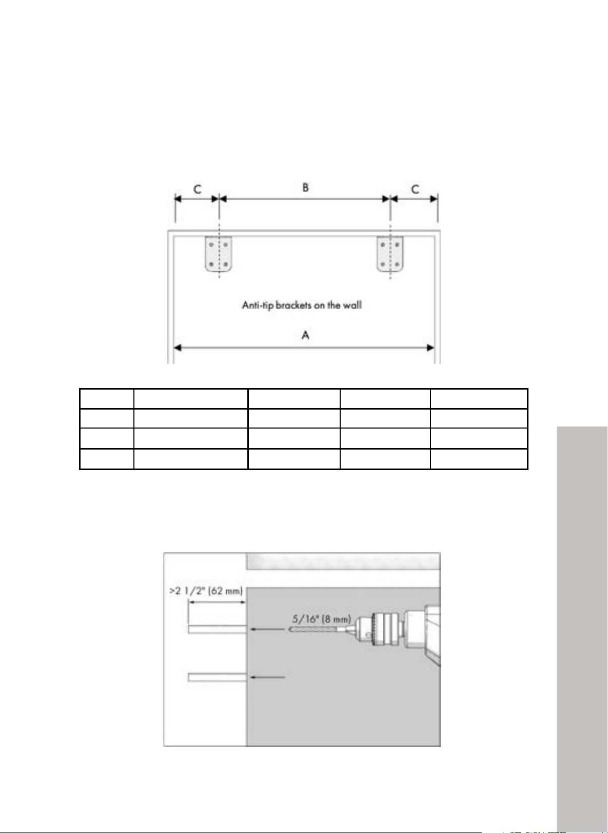
• Mark the upper rear of the wall in your cabinet cutout to locate the anti-tip brackets (page
26, Item No. 2).
Category RBCFVL-18/RBCFVR-18 RBCFV-24 RBCRV-24 RBCRV-30
A 18 3/16" (462 mm) 24 3/16" (614 mm) 24 3/16" (614 mm) 30 3/16" (767 mm)
B 11 5/8" (295 mm) 17 5/8" (447 mm) 17 5/8" (447 mm) 23 5/8" (600 mm)
C 3 3/16" (81 mm) 3 3/16" (81 mm) 3 3/16" (81 mm) 3 3/16" (81 mm)
• Use a 5/16" (8 mm) drill bit to bore roughly 2 1/2" (62 mm) deep holes at the marked
points. Do not use a larger drill bit as the wall anchors will be unable to tighten or secure
the brackets.
Anti-Tip Brackets
31
INSTALLATION
MOUNTING THE ANTI-TIP BRACKETS
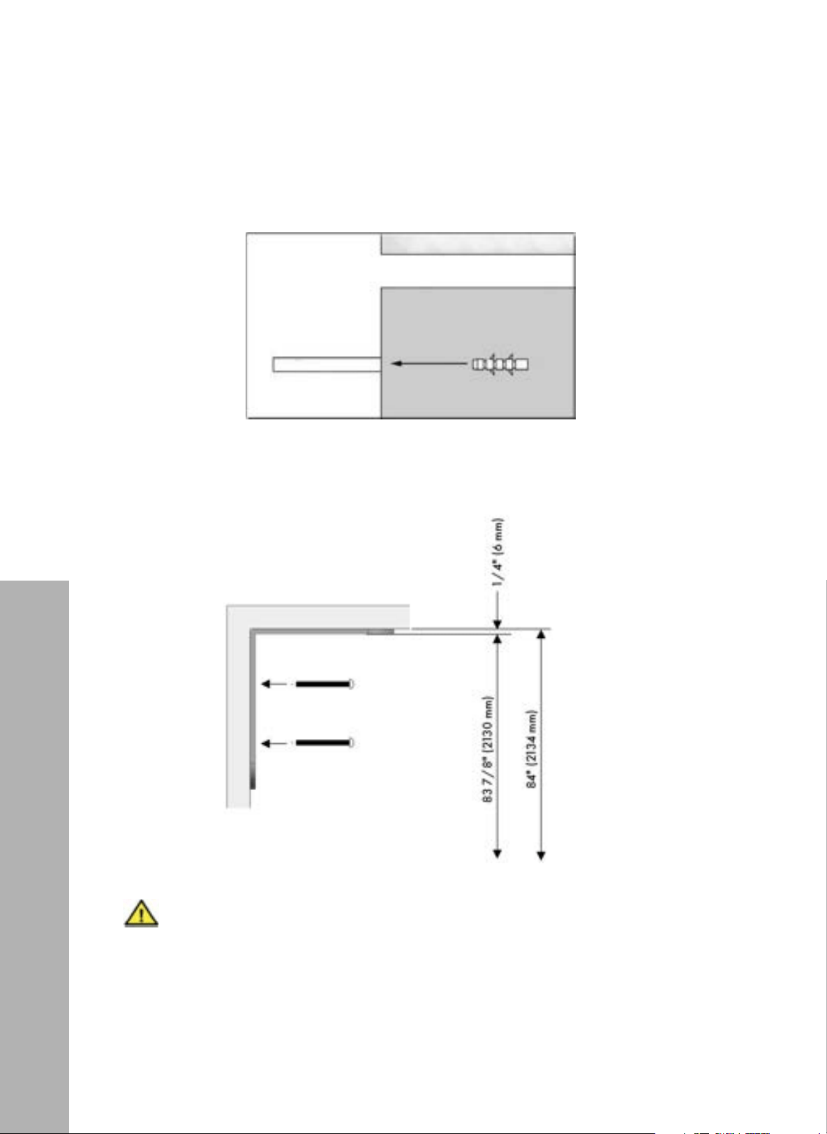
• Use the hammer to tap anti-tip anchors (page 26, Item No. 2) into the wall.
• Fit the anti-tip brackets into their places, using four screws (page 26, Item No. 1) for
each. You must use both brackets to ensure safety of the product.
• If you are not sure whether the anti-tip brackets are fastened to the wall as
securely as they should be, you can use alternative anti-tip methods.
• If there are cabinets at the back wall of the refrigerator or freezer, please
make sure the cabinets are fixed to the wall. For this, you need to ensure the
back wall of the cabinets are fixed to the concrete back wall with suitable
connection parts.
WARNING
Anti-Tip Brackets
32
INSTALLATION
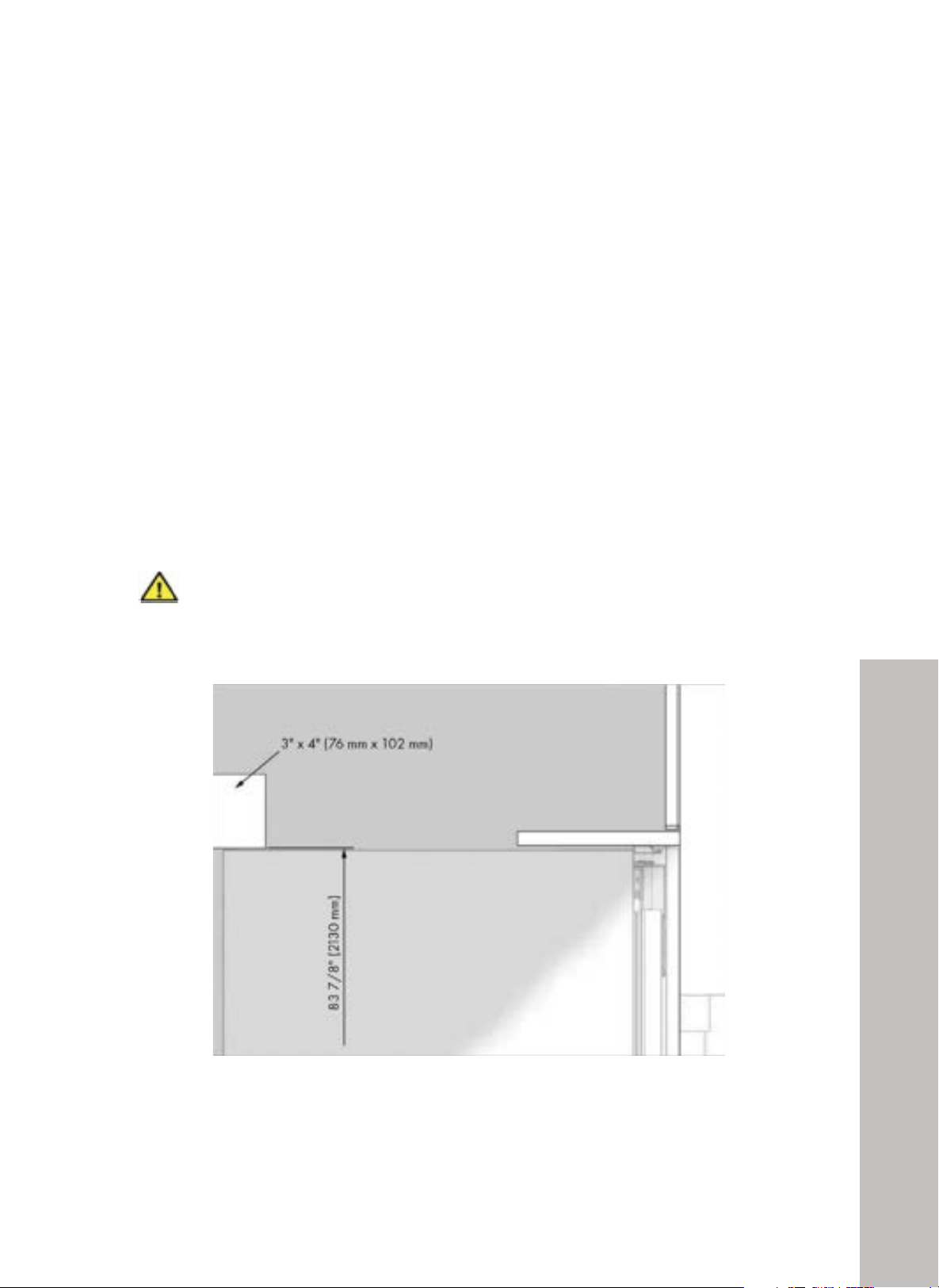
ALTERNATIVE ANTI-TIP METHOD
• If the anti-tip brackets cannot be connected securely, you must use the alternative method
outlined below.
• In this method, you can use wooden blocks (not provided) to avoid the risk of the unit
tipping over. They must be installed as illustrated in the figure below.
• There must be no clearance between the product and the wooden blocks.
• Minimum section dimensions of the wooden block must be 3" by 4" (76 mm by 102 mm).
The width of the blocks must be equal to the clearance where it will be installed.
• An additional block must be used if the niche depth is more than anticipated. The wooden
block must contact the product with a maximum depth of 2" (51 mm).
• To determine the location for the wooden block, mark it on the rear wall, select suitable
screws, and connect safely.
The number and type of the screws to be used for the wooden block must be
determined so there is a secure connection. Only a professional installer should
perform this alternative method.
WARNING
Anti-Tip Brackets
33
INSTALLATION
PREPARING THE WATER HOSE AND POWER PLUG
• You will need a hose with a minimum length of 60" (1524 mm) and a diameter of 1/4"
(6 mm) for water connections during installation.
•
A connector that has a thread with an external diameter of 1/4" (6 mm) must be used to
connect the hose end to the product.
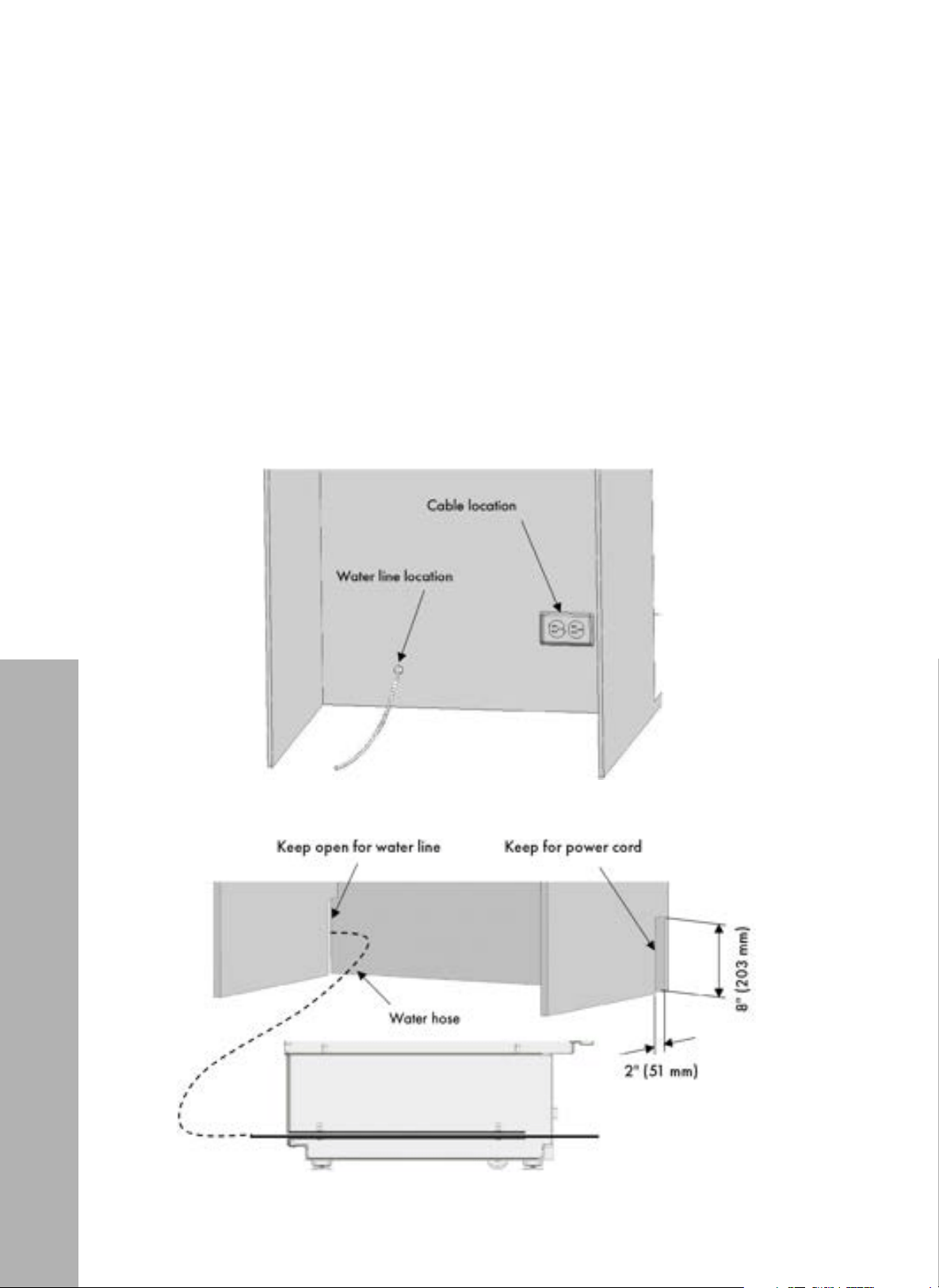
• You can choose method A or method B below to prevent the power cord and water supply
line from getting jammed or tangled.
Method A: Locate the water hose and power supply on the back of your cabinet.
Method B: Locate the water hose and power supply through the side of the cabinet.
Water Hose and Power Supply
34
INSTALLATION
MOVING THE UNIT FROM THE WOODEN PALLET
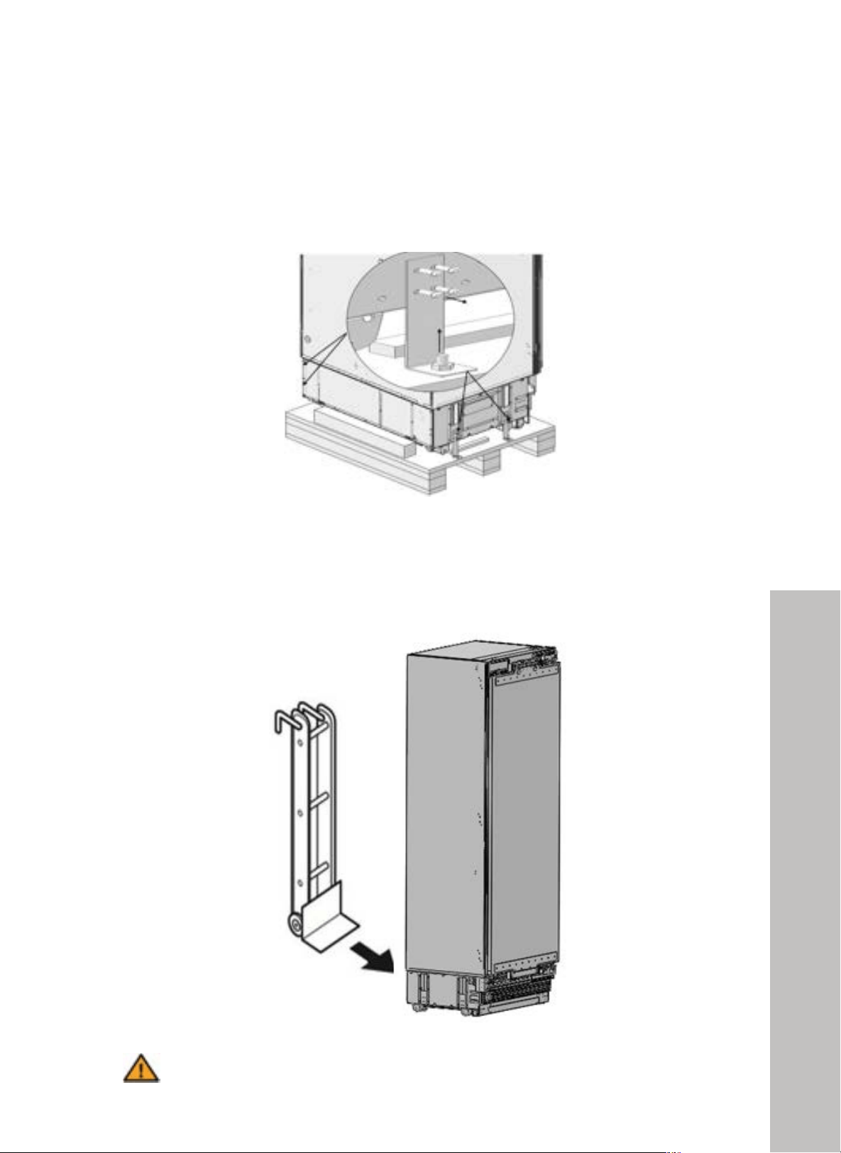
• With a Phillips-head screwdriver or drill bit, remove the screws from the security brackets
that connect the refrigerator or freezer to the wooden pallet as outlined below.
• With at least two people, recline the appliance with the help of a dolly/hand truck to lift it
off the pallet and Styrofoam packaging, then slowly lower the refrigerator to the floor. Then,
use the hand truck to carefully move the unit near the opening of the cabinet cutout where
it will be installed.
!"#$%&'#(%)*! !
$!"
"
3;!,7887,3>;(,>(,H9(@7I3;(
!
,)E/*2(4-.(0.A0/2.0)4%0(A0%#(4-.(B%%+.*(5)&&.4(
•! D8.0Q8">78"/:3@P8>2">73>"@0448@>">78":8K:9;8:3>0:">0">78"X00584"I3118><"
!
+
!
!
!
!
•! D8@1948">78":8K:9;8:3>0:"210L1-"345"?M11"/3@P"L9>7">78"781?"0K">78"@3:>\"345">784"1345"9><"
!
!
!
!
!
!
!
!
!
!
!
!
!
!
!
!
!
!
!
!
!
!
!
!
!
!
!
!
!
!
! "))*$)%+$'(
678":92P"0K">9??94;"0Q8:"92"79;7"32"0K">792"?094><"]0M"270M15"40>"0?84">78"500:2" "
M4>91">78"?:05M@>"92"?13@85"94>0">78"@3/94<"
!
!
!
!
!
!
ATTENTION
Do not open doors, as the weight of the unit's doors can cause the appliance to
tip over while in a reclined or free standing position.
Moving the Unit
35
Preparing the Water Line
PREPARING FOR PLACING THE UNIT INTO THE CABINET
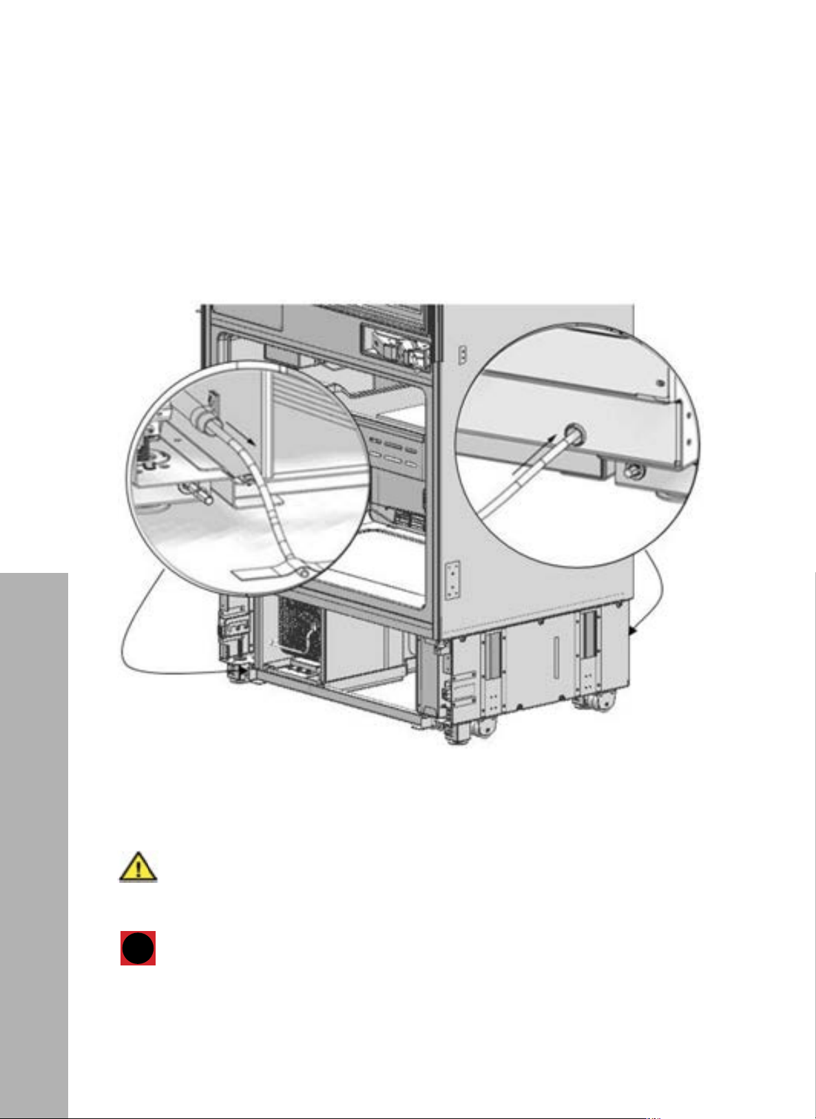
• Before preparing to push the unit into the cabinet cutout, run the water line hose through the
rear channel of the refrigerator or freezer (below image, right circle) to the front of the unit
(below, left). You can optionally tape the water line to the floor to avoid it getting tangled
during installation.
• Plug in the refrigerator or freezer to make sure the power is working and that the display
has been activated.
WARNING
The plug of the product must be accessible after installation. If the plug is not
accessible after installation, the power must be cut off from the main switch.
i
You can use tape or other protective items you think are necessary to protect
the edges of the cabinet when placing the product.
INFO
INSTALLATION
36
Preparing for Placement
INSTALLATION
PLACING THE UNIT INTO THE CABINET
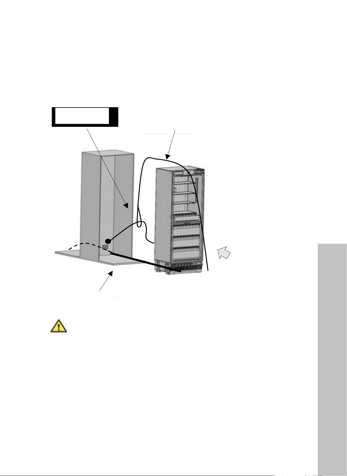
• Apply the below method — tie a nylon string or other durable string/cable around the
power cord — to prevent the power cord from getting jammed.
!"#$%&'#(%)*! !
$$"
"
!
!
%,-+#)"$)(%$.+#,")%+$'(
!
•! A??1-">78"/810L".8>705">0"?:8Q84>">78"@3/18"K:0.";8>>94;"V3..85<"
+
+
"
"
"
"
"
"
"
"
"
"
"
"
"
"
"
"
"
•! ,>3:>">78":8K:9;8:3>0:"345".3P8"2M:8"9>"92"848:;9^85<"
" `]0M"@34"@78@P"9K">78"13.?2"@0.?3:>.84>"3:8"04"0:"0KK">0"288"9K">78"?:05M@>"92"0?8:3>94;a<"
!
!
%,-+#)"$)(%$.+#,")%+$'(
]0M"@34"M28">3?8"345"29.913:"?:0>8@>0:2"04"?3:>2"-0M">794P">792"92"48@8223:-">0"?:0>8@>">78"85;82"0K">78"KM:49>M:8"
L784"?13@94;">78"?:05M@><"
!
!"#$%$&'(
678"?1M;"0K">78"?:05M@>".M2>"/8"3@@8229/18"3K>8:"942>3113>904<"=K">78"?1M;"92"40>"3@@8229/18"3K>8:"942>3113>904\">78"?0L8:"
.M2>"/8"@M>"0KK"K:0.">78".394"2L9>@7<"
!
!
!"#$%$&'(
S3P8"2M:8">73>">78".3942"@3/18"92"40>"V3..85"L784"?13@94;">78"?:05M@><"
!
!! IM27">78"?:05M@>"@3:8KM11-">0L3:52">78"@3/94">0"?13@8"9><" !
=K">78:8"92"2>:394"5M:94;">78"?13@8.84>"0K">78"?:05M@>"94>0">78"@3/94[!
R! 678"K100:".9;7>"/8":0M;7"0:"M48Q84"
R! A5VM2>3/18"K88>".9;7>"/8"10028"
`?18328"288">78":818Q34>"28@>904">0"183:4"70L">0"35VM2>">78"35VM2>3/18"K88>a"
(
(
BC?+>),&(@>D)
:+;'()<+(=)
$%&'()*+,')
E+F')&+);%??)
Move to wall
Water hose
Power cord
Nylon string
WARNING
Make sure the power cable is not jammed when placing the product, or else you
increase the risk of electric shock or power failure.
• Push the product carefully toward the cabinet cutout. If there is strain of any kind during
placement of the product into the cabin:
• the floor might be rough or uneven; and/or
• adjustable feet might be loose (please see page 38 to learn how to adjust the
adjustable feet to level the product).
37
Preparing for Placement
ALIGNING THE UNIT WITH THE CABINET CUTOUT
i
It is very important to align the upper edge of both doors when aligning. All the
other edges can be adjusted with the adjustment mechanisms.
INFO
NOTE: The image below is of a refrigerator or freezer with panels installed in order to show
proper gaps when aligning the door.
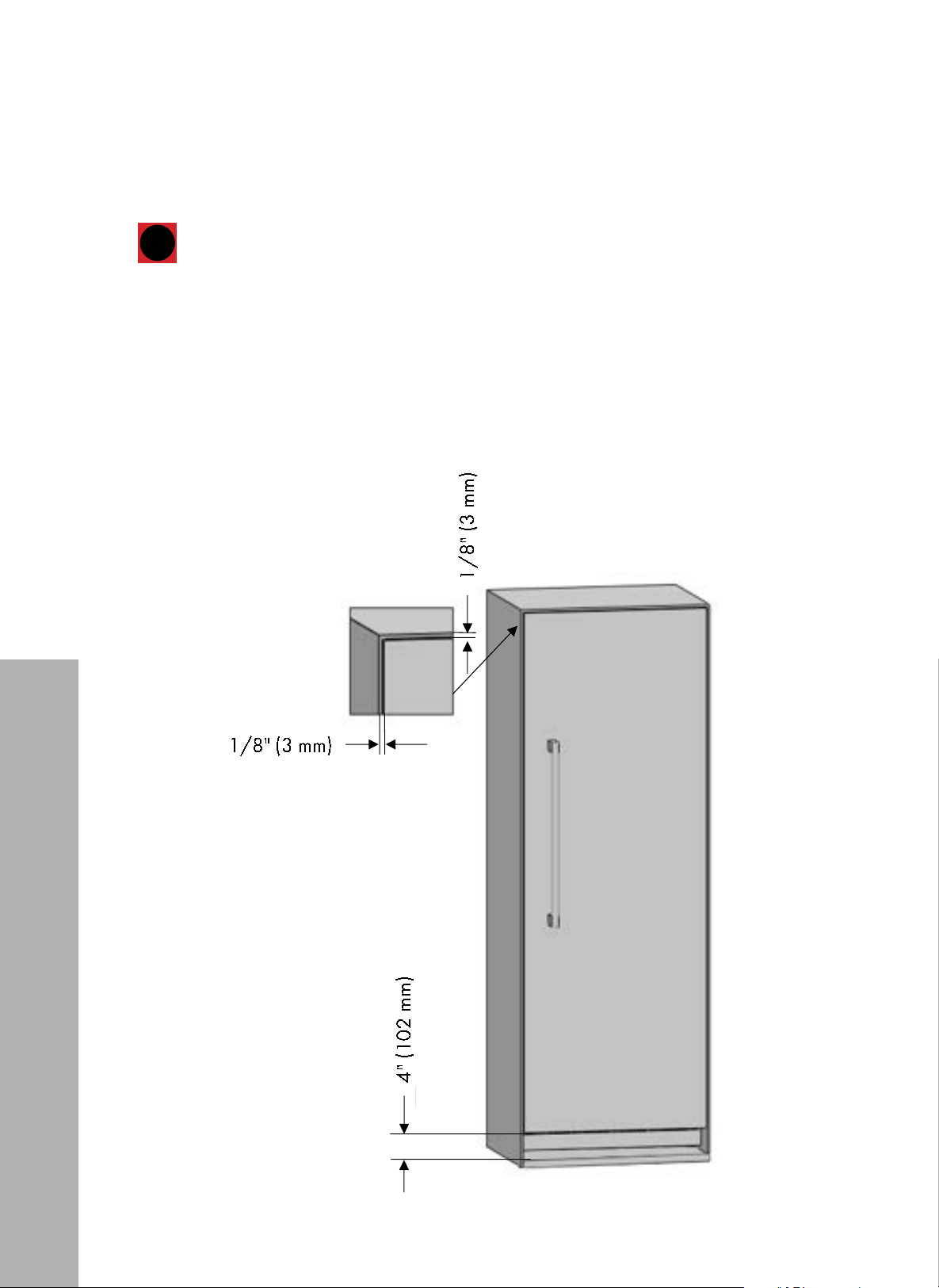
• 1/8" (3 mm) represents the required gap between door panels and the cabinet cutout.
• These gap measurements are the same for custom panels and ZLINE-provided panels.
• Door panel preparation and installation is covered starting on page 54.
!"#$%&'#(%)*! !
$%"
"
%,-+#)"$)(%$.+#,")%+$'(
]0M".M2>"M28">78"M??8:"85;82"0K">78"'00:"L784"319;494;">78"?:05M@>"L9>7">78"KM:49>M:8<"
A5VM2>.84>"0K"0>78:"85;82"3:8"8_?139485"94">78"K0110L94;"?3;82<"
!
!
!
!
!
!
!
!
!
!
!
!
!
!
!
!
!
!
!
!
!
4,)>-7-FF@!
-D.
,)>6FF@!
-D.,)>6FF@
!
1/8" (3 mm)
4" (102 mm)
1/8" (3 mm)
INSTALLATION
38
Adjusting the Legs
INSTALLATION
ADJUSTING THE REFRIGERATOR HEIGHT
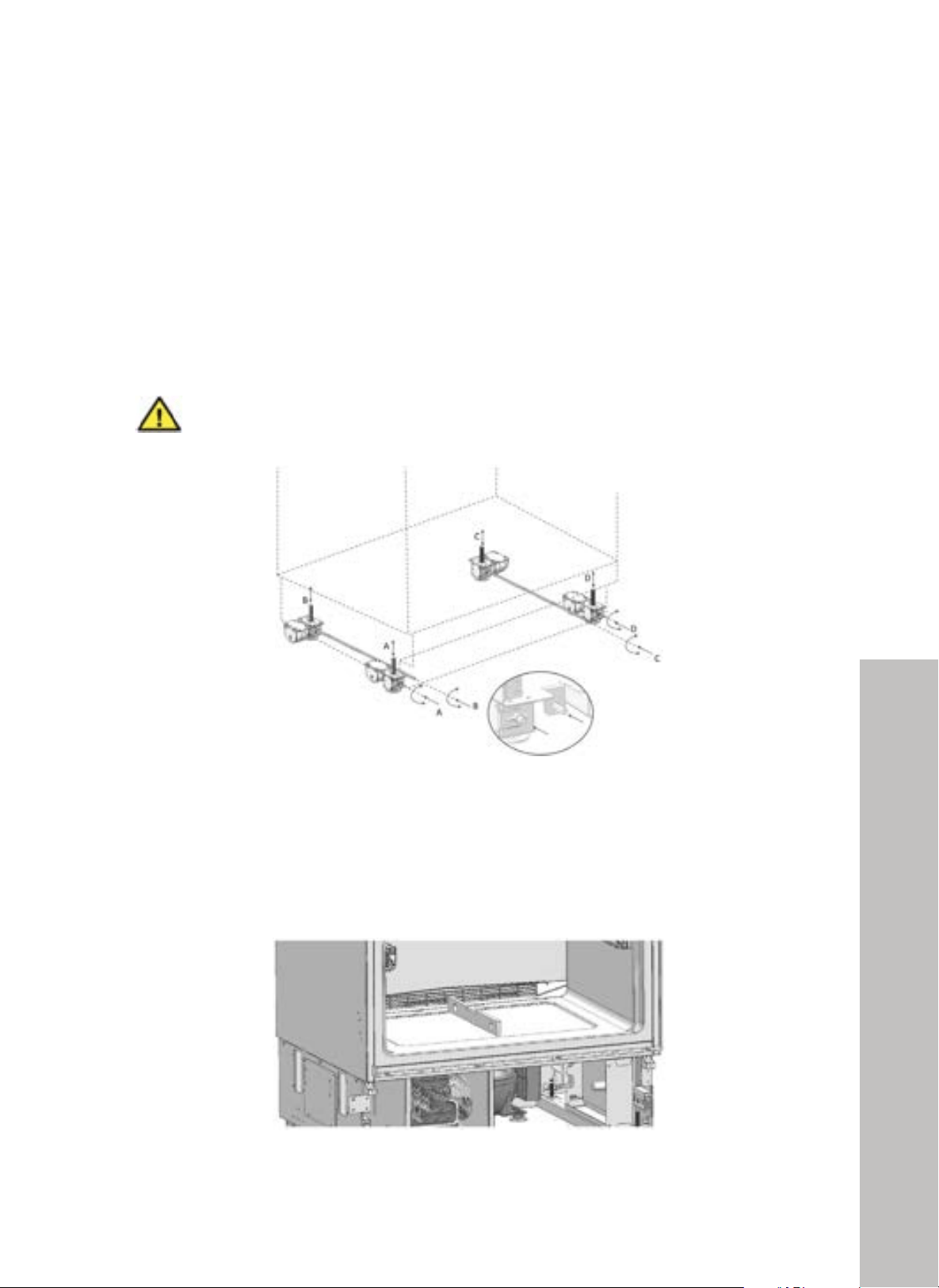
• With the unit now aligned, push it carefully into the cabinet cutout.
• Next, the feet need to be raised in order to secure the product to the anti-tip brackets.
• You may use a socket wrench with a 1/4" hex bit to adjust leg height; we recommend using
a socket wrench by hand to avoid the risk of stripping the legs. Do not use an impact drill
to adjust the feet; doing so may cause damage.
WARNING
It's important to raise the front feet first to reduce risk of the appliance falling
frontward, which would increase the risk of injury.
A/D — Turn the key clockwise to lift the front
B/C — Turn the key clockwise to lift the rear
• After adjusting the feet, check if the product is level in both width and depth directions. You
may readjust as needed after the panel is installed.
• The maximum height the adjustable feet can reach is 1 9/16" (40 mm), and the maximum
product height is 85 3/8" (2169 mm).
39
Aligning the Unit
ALIGNING THE UNIT WITH THE CABINET CUTOUT
i
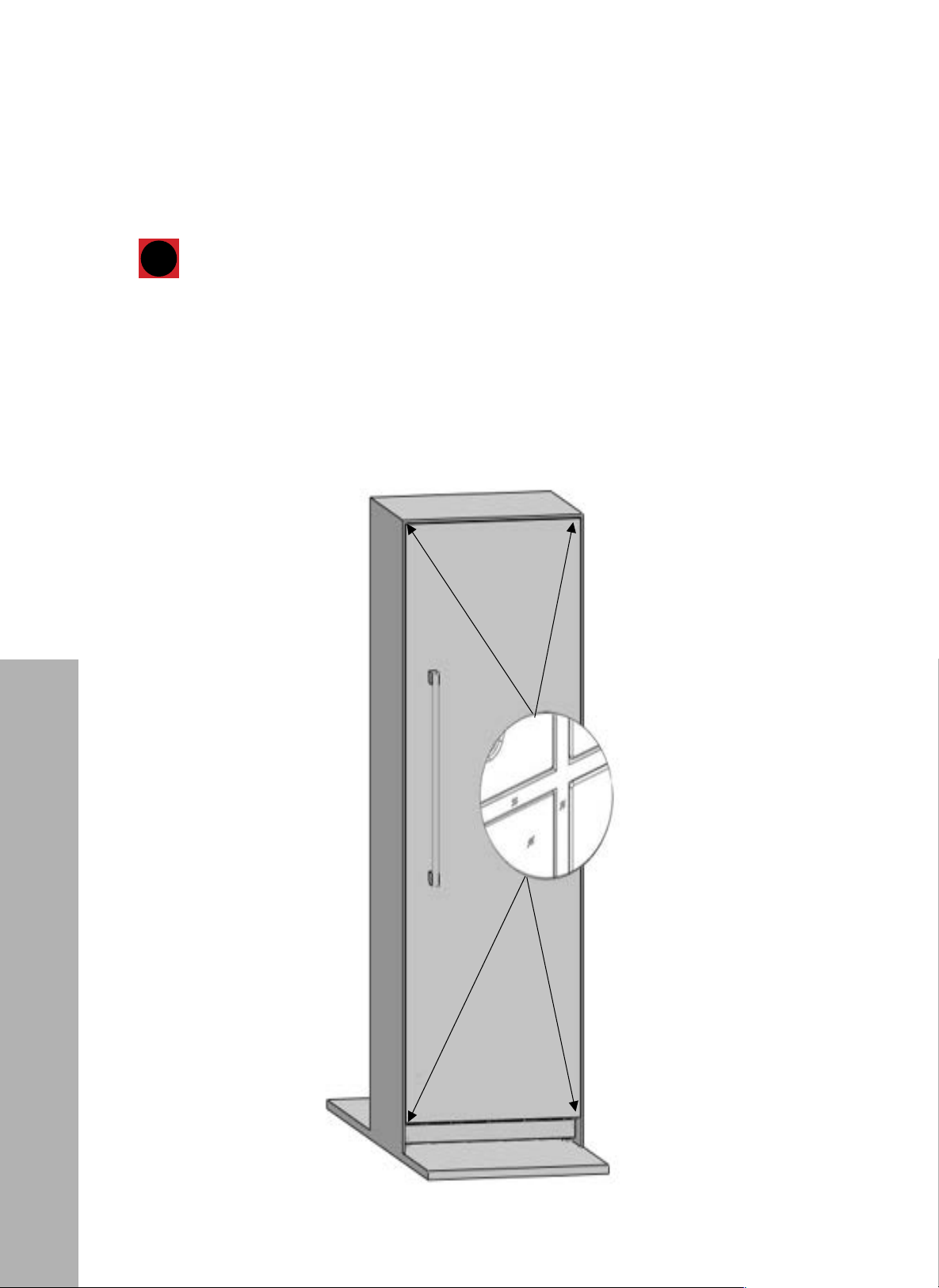
It is very important to align the upper edges of the doors when aligning. All the
other edges can be adjusted with the adjustment mechanisms.
INFO
If this refrigerator or freezer was purchased with a ZLINE-provided door panel, the position of
the unit needs to be adjusted so that the door and the cabinet surface are flush, as shown in the
figure below. You can also use a position alignment gauge (page 26, Item No. 3) as shown
on page 40 if necessary for alignment.
!"#$%&'#(%)*! !
$'"
"
!
7+JC'4/*2(4-.(0.A0/2.0)4%0()66%0+/*2(4%(4-.(6)$/*(A&)*2.(
"
•! G0:"?:05M@>"L9>7"KM:49>M:8"500:\">78"?029>904"0K">78"D8K:9;8:3>0:"92"35VM2>85" "
20">73>">78"500:"345">78"KM:49>M:8"2M:K3@8"3:8"K1M27<" "
]0M"@34"3120"M28";3;8"9K"48@8223:-<"
+
!
!
!
!
!
!
!
!
!
!
!
!
!
!
!
!
!
!
!
!
!
!
+
!
!
!
!
!
!
!
!
!
!
!
!
!
!
!
!
!
!
!
!
!
!
!
!
!
!
!
!
!
!
!
!
INSTALLATION
40
Aligning the Unit
INSTALLATION
USING THE POSITION ALIGNMENT GAUGE
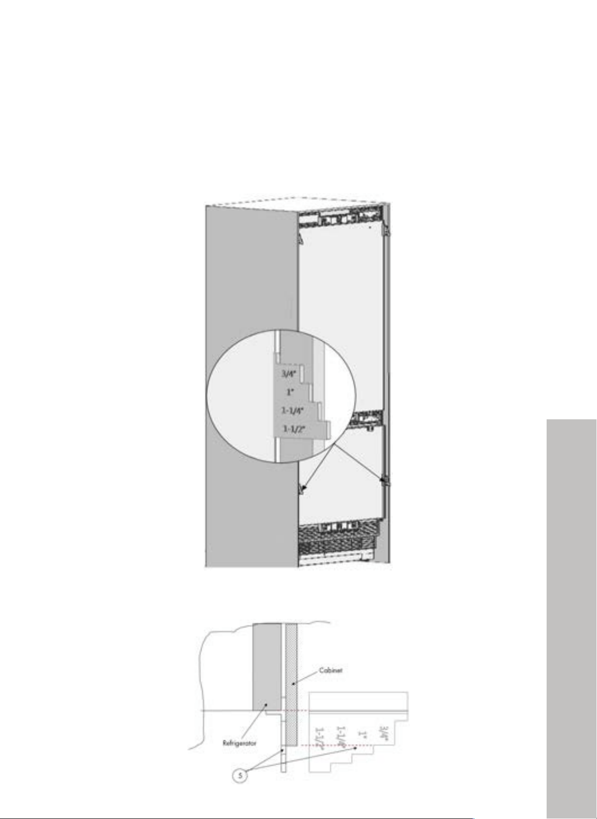
• If this refrigerator or freezer was purchased without a ZLINE-provided door panel, the
product can be placed using the position alignment gauge (Item No. 3) as outlined below
in order to align with custom panels, which vary in size and thickness.
• The position of the position alignment gauge must be adjusted according to the thickness of
the door. It can adjust to four different door thickness levels.
41
INSTALLATION
ATTACHING THE CABINET MOUNTING BRACKETS
• Fix the cabinet mounting bracket (Item No. 12) to the unit, with 2 on the top and 3 on every
side. Use the screws to secure cabinet mounting bracket to side and top of refrigerator (Item
No. 14) to tighten.
WARNING
Before starting to screw the side and upper brackets, please make sure that water
is supplied to the product and there is no water leakage.
!"#$%&'#(%)*! !
$)"
"
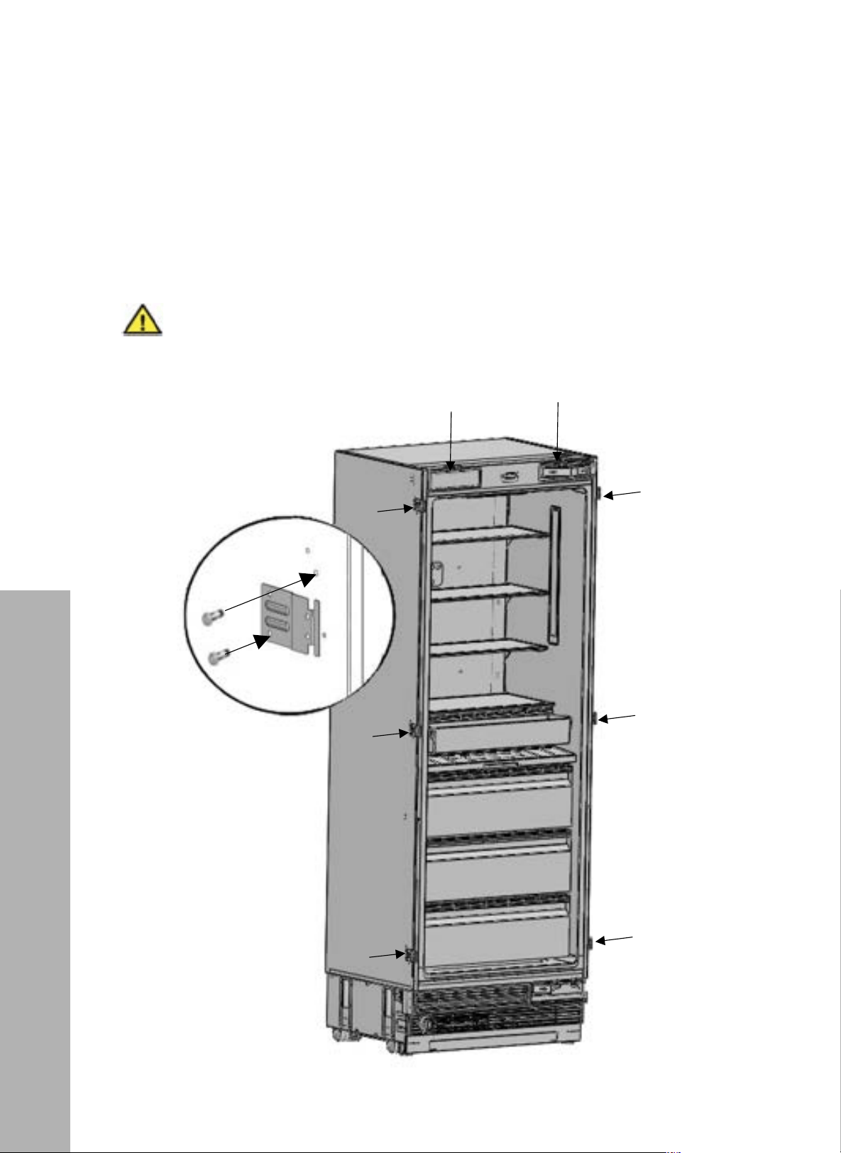
!60.B/*2(4-.('/+.()*+(C55.0($0)6E.4'!
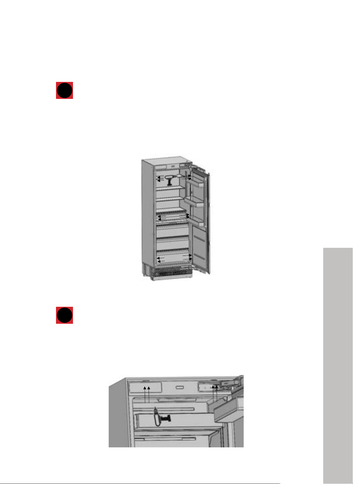
•! G9_">78"/:3@P8>"KM:49>M:82"`=>8."E0!#a">0">78"M49>\"L78:8"#"04">78">0?\"345"$"04"8Q8:-"2958<" "
O28">78">:M22"L3278:"7835"2@:8L2"`=>8."E0!%a">0">9;7>84<"
!
!
!
! !"#$%$&'(
U8K0:8"2>3:>94;">0"2@:8L">78",958"345"O??8:"/:3@P8>2\"?18328".3P8"2M:8">73>"L3>8:"92"2M??1985">0">78"?:05M@>"345"
>78:8"92"40"L3>8:"183P3;8<"
Adjusting the Brackets
42
SECURING THE UNIT TO THE CABINET CUTOUT
i
If you have difficulty tightening the screws, opening a reference hole with the
drill will make this procedure easier.
INFO
Screwing the cabinet mounting bracket on the cabin side wall
• Attach the cabinet mounting bracket to the cabinet with 12 screws (Item No. 13).
!"#$%&'#(%)*! !
$*"
"
+
+
!
%,-+#)"$)(%$.+#,")%+$'(
=K"-0M"73Q8"59KK9@M1>-">9;7>8494;">78"2@:8L2\"0?8494;"3":8K8:84@8"7018"L9>7">78"5:911"L911".3P8">792"?:0@85M:8"83298:<"
<,('F)*+%.1'%&(#,G'.%04(*).4('%"*%.1'%,#&)*%2)$'%F#77%
•! A>>3@7">78"/:3@P8>"KM:49>M:8">0">78"KM:49>M:8"L9>7"!#2@:8L2"`=>8."E0!$a<"
"
"
/
"
"
! %,-+#)"$)(%$.+#,")%+$'(
=K"-0M"73Q8"59KK9@M1>-">9;7>8494;">78"2@:8L2\"0?8494;"3":8K8:84@8"7018"L9>7">78"5:911"L911".3P8">792"?:0@85M:8"83298:"
"
<,('F)*+%.1'%&(#,G'.%04(*).4('%"*%.1'%,#&)*%."-%F#77%
•! A>>3@7">78"/:3@P8>"KM:49>M:8">0">78"KM:49>M:8"L9>7"%2@:8L2"`=>8."E0!$a<"
"
"
!
i
If you have difficulty tightening the screws, opening a reference hole with the
drill will make this procedure easier.
INFO
Screwing the cabinet mounting bracket on the cabin top wall
• Attach the cabinet mounting bracket to the cabinet with 4 screws (Item No. 13).
!"#$%&'#(%)*! !
$*"
"
+
+
!
%,-+#)"$)(%$.+#,")%+$'(
=K"-0M"73Q8"59KK9@M1>-">9;7>8494;">78"2@:8L2\"0?8494;"3":8K8:84@8"7018"L9>7">78"5:911"L911".3P8">792"?:0@85M:8"83298:<"
<,('F)*+%.1'%&(#,G'.%04(*).4('%"*%.1'%,#&)*%2)$'%F#77%
•! A>>3@7">78"/:3@P8>"KM:49>M:8">0">78"KM:49>M:8"L9>7"!#2@:8L2"`=>8."E0!$a<"
"
"
/
"
"
! %,-+#)"$)(%$.+#,")%+$'(
=K"-0M"73Q8"59KK9@M1>-">9;7>8494;">78"2@:8L2\"0?8494;"3":8K8:84@8"7018"L9>7">78"5:911"L911".3P8">792"?:0@85M:8"83298:"
"
<,('F)*+%.1'%&(#,G'.%04(*).4('%"*%.1'%,#&)*%."-%F#77%
•! A>>3@7">78"/:3@P8>"KM:49>M:8">0">78"KM:49>M:8"L9>7"%2@:8L2"`=>8."E0!$a<"
"
"
!
INSTALLATION
Adjusting the Brackets
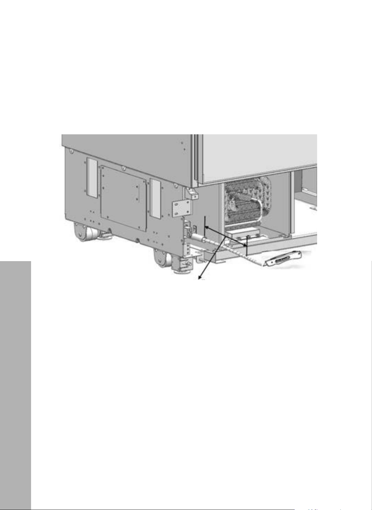
43
INSTALLATION
INSTALLING THE WATER CONNECTION
• With the unit secured into the cabinet cutout, use two wrenches to firmly connect the main
water line hose from the front of the unit to the hose coming from the valve above, as
outlined in the image below.
!"#$%&'#(%)*! !
%+"
"
!
3;!,7883;K(,H9(@7I3;(I>,,>1(
L)4.0(6%**.64/%*(
•! O28">78"/0_"@M>>8:">0"@M>">78"L3>8:"7028"K:0.">78"845"0K">78"?9?8"9>"@0.82"0M>\"
183Q94;"3"28@>904"0K"!+e"184;>7<"
"
!
!
•! O28">78"#"L:84@782">0"K9:.1-"@0448@>">78"7028"@0.94;"K:0.">78".3942"345" "
>78"7028"@0.94;"K:0.">78"Q31Q8<"
! !"#$%$&'(
678"7028"@0.94;"K:0.">78".3942".M2>"/8"048"?98@8<"Y0"40>"M28"8_>842904"70282<"
!
! !"#$%$&'(
S3P8"2M:8">73>">78"?0L8:"92"@M>"0KK"L784".3P94;">78"L3>8:"@0448@>904"0K">78"?:05M@><"
!
! !"#$%$&'(
678"L3>8:"Q31Q8".M2>"/8"0KK"L784"@0448@>94;">78"L3>8:"7028<"
!
! !"#$%$&'(
=>"92":8@0..84585">73>">78"L3>8:"04g0KK"Q31Q8":8.3942"3@@8229/18"3K>8:"942>31194;">78"?:05M@><"
"
! !"#$%$&'(
6792"?:05M@>"92"2M9>3/18"K0:"M28"L9>7"@015"L3>8:".3942"041-<"
10" (250 mm)
• Once the water connection is complete, you must turn on the main water valve to ensure
there are no water leaks.
• This also allows you to run water through the unit's water dispenser to drain the water
filtration system before use.
• If necessary, use the box cutter to cut the water hose from the end of the pipe it comes out
of, leaving a section of 10" (254 mm) length to avoid excess length.
• Use the 2 wrenches to firmly connect the hose coming from the mains and the hose coming
from the valve.
Water Connection
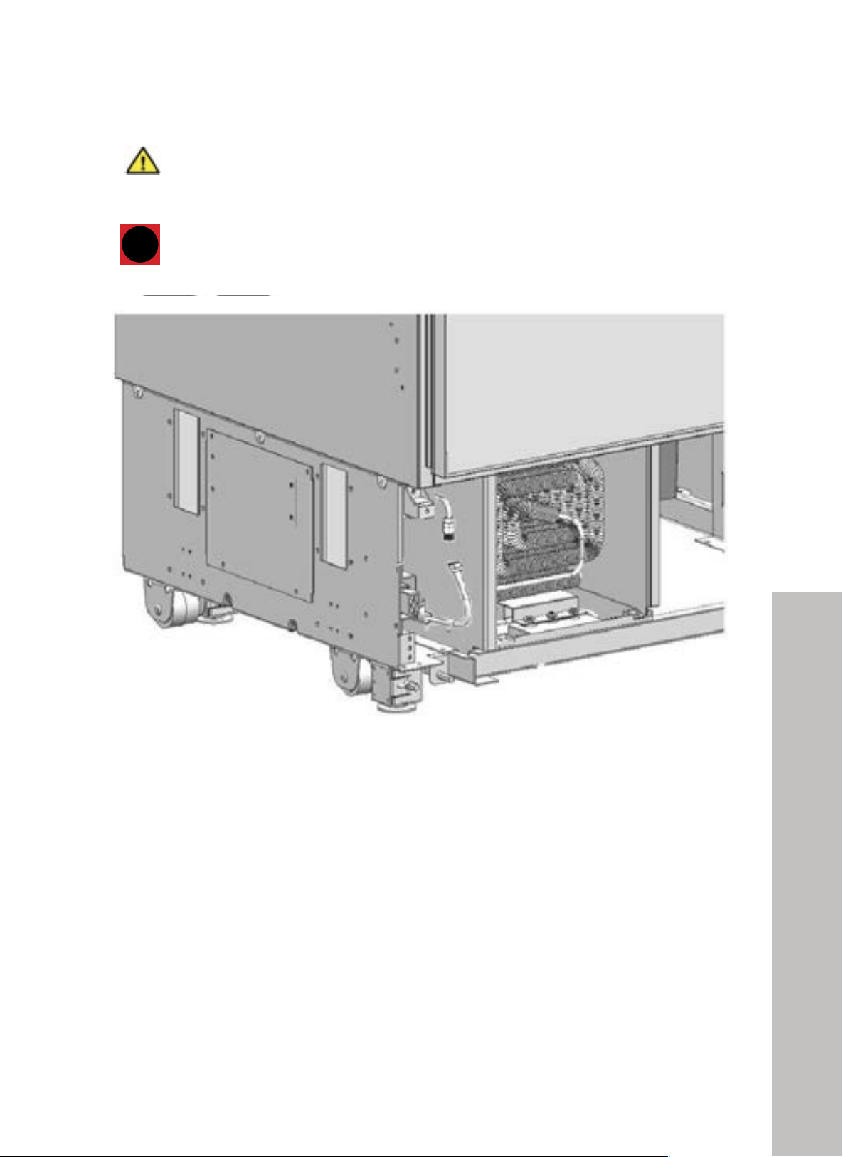
44
Water Connection
INSTALLATION
WARNING
Pressure of the water system must be between 25-80 psi (1.7-5.5 bar).
!"#$%&'#(%)*! !
%!"
"
!"#$%$&'(
I:822M:8"0K">78"L3>8:"2-2>8.".M2>"/8"/8>L884"#&R)+"?29"`!<(R&<&"U3:a<"
!
! %,-+#)"$)(%$.+#,")%+$'(
H4@8">78"@0448@>904"92"@0.?18>8\"-0M".M2>">M:4"04">78".3942"Q31Q8"345".3P8"2M:8" "
>73>">78:8"92"40"183P3;8"3>">73>"?094><"
!
!
i
Once the water connection is complete, you must turn on the mains valve
and make sure that there is no leakage at that point.
INFO

45
INSTALLATION
WARNING
WATER SAFETY MEASURES
• The main water line hose must be one piece. Do not use extension hoses.
• Make sure power to the unit is turned off from the breaker when making the water
connection of the product to limit risk of electric shock.
• The water valve must be off when connecting the water hose.
• It is recommended that the water on/off valve remains accessible after installing the
product in the event service is needed.
• This product is suitable for use with cold water mains only.
• The pressure of the water system must be between 25-80 psi (1.7-5.5 bar).
• If the water pressure exceeds 80 psi (5.5 bar), install a pressure-limiting device or water
pressure protector to the inlet valve. Never install or operate the appliance if it's possible
for the water pressure to exceed 120 psi (8.3 bar).
• If the water pressure is lower than 14.5 psi (1 bar), you can use an auxiliary pump
to compensate.
• If you do not know how to check the water pressure or are unsure how to utilize an
auxiliary pump, please consult a professional plumber.
DUAL CABIN INSTALLATION
• If combining multiple units, please note both refrigerators and freezers have a
dedicated water supply, each requiring a hose with a minimum length of 60"
(1524 mm) and a diameter of 1/4" (6 mm) for proper water connections.
•
If the plumbing of your home needs alteration to accommodate built-in refrigeration, a
qualified technician or professional plumber may tee off the water supply to provide water
to both units if the customer desires.
• Read more about dual unit installation on page 10.
Water Connection
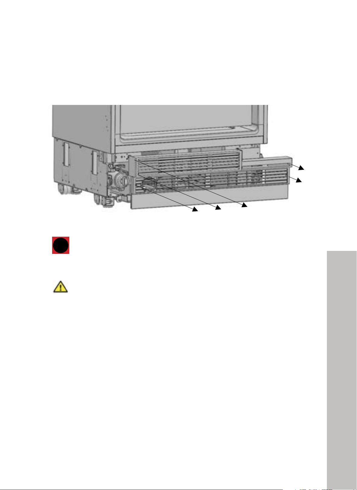
46
Re-Attaching the Vent Panels
INSTALLATION
ATTACHING THE VENT HOLE ASSEMBLY
• Use 5 screws to attach the vent hole assembly.
"
#&"
"
:.#%F/*2(4-.(F.*4(-%&.()''.#$&"(
•! D8.0Q8"&"2@:8L2">0">3P8"0M>">78"F84>"T018""A228./1-<"
+
+
!
!
!
!
+
"
"
"
"
"
"
"
"
!"#$%&'#(%)*! !
#%"
"
:.#%F/*2(#%C*4/*2(5)04'(/*(4-.(+0)B.0(6%#5)04#.*4(
%
"
"
"
"
"
"
"
"
"
"
"
"
+
!
!
!
!
!
!
!
!
!
!
!
!
!
!
!
!
!
!
!
!
!
!
!
!
1&)
]"'#)L"F$)
^K$Q)
-.)
34)
67)
P$F"'?)
-)
2L#H,#HK)<'"Q?$#)
*4V7a) ) !'bcL,Q&"#HL%)
.)
.)
.)
)
3)
2L#H)#HK)<'"Q?$#)=Q'$G=)"L;);&G$:=)
8.d5E7)
.)
.)
.)
)
6)
]&=H#H&L)";SJ=#F$L#)SH%)
]^)
-)
-)
-)
)
4)
!&T$')RJ'LH#J'$);&&')<'"Q?$#)
"<=)
,)
3)
3)
)
A)
*'J==)G"=I$')I$";)
84d-3)
,)
3)
3)
)
E)
/'"Q?$#)RJ'LH#J'$);&&')
*-V7a) ) !'bcL,Q&"#HL%)
,)
3)
3)
)
B)
!&JL#$')=JL?)I$";)=Q'$G)
^*49-4)
,)
4)
4)
)
.)
*'J==)G"=I$')I$";)
84d-3)
4)
4)
4)
)
C)
^eJ"'$)G"=I$')
*-V7a) ) !'bcL,Q&"#HL%)
4)
4)
4)
)
-7)
!$L#$')F&JL#HL%)<'"Q?$#)
*-V7a) ) !'bcL,Q&"#HL%)
4)
4)
4)
)
--)
!&JL#$')=JL?)I$";)=Q'$G)
^*49-4)
.)
.)
.)
)
-3)
/'"Q?$#)RJ'LH#J'$) )
*-V7a) ) !'bcL,Q&"#HL%)
.)
.)
.)
)
-6)
!&JL#$')=JL?)I$";)=Q'$G)
^*)849-4)
-E)
-E)
-E)
)
-4)
*'J==)G"=I$')I$";)
84d-3)
-E)
-E)
-E)
)
-A)
!&JL#$')=JL?)I$";)=Q'$G)))
^*)849-4)
-E)
37)
37)
+J'LH#J'$);&&')I"L%$')<'"Q?$#)
-E)
2H')T$L#)IHL%$)K"'#)
2/^)
,)
-)
-)
O&&')&K$LHL%);H'$Q#H&L)QI"L%$)
-B)
C7f:HFH#)KHL)
g4)
3)
3)
3)
O&&')C7f&K$LHL%)J=$)
!! 2L#H)#HK)<'"Q?$#)=Q'$G=) )
!! ;&G$:="
!! !&JL#$')=JL?)I$";)=Q'$G)
^K$Q)M)^*)849-4)
+H9HL%)#I$)Q"<HL)"L;)
RJ'LH#J'$);&&')
>G&&;)K"'#@)
!! *'J==)G"=I$')I$";)=Q'$G"
^K$Q)M)849-3)
+H9HL%)P$R'H%$'"#&')
^JQI)"=)Q"<HL$#)"L;);&&')
>K'$==)K"'#@)
!"#$%&'#(%)*! !
#%"
"
:.#%F/*2(#%C*4/*2(5)04'(/*(4-.(+0)B.0(6%#5)04#.*4(
%
"
"
"
"
"
"
"
"
"
"
"
"
+
!
!
!
!
!
!
!
!
!
!
!
!
!
!
!
!
!
!
!
!
!
!
!
!
1&)
]"'#)L"F$)
^K$Q)
-.)
34)
67)
P$F"'?)
-)
2L#H,#HK)<'"Q?$#)
*4V7a) ) !'bcL,Q&"#HL%)
.)
.)
.)
)
3)
2L#H)#HK)<'"Q?$#)=Q'$G=)"L;);&G$:=)
8.d5E7)
.)
.)
.)
)
6)
]&=H#H&L)";SJ=#F$L#)SH%)
]^)
-)
-)
-)
)
4)
!&T$')RJ'LH#J'$);&&')<'"Q?$#)
"<=)
,)
3)
3)
)
A)
*'J==)G"=I$')I$";)
84d-3)
,)
3)
3)
)
E)
/'"Q?$#)RJ'LH#J'$);&&')
*-V7a) ) !'bcL,Q&"#HL%)
,)
3)
3)
)
B)
!&JL#$')=JL?)I$";)=Q'$G)
^*49-4)
,)
4)
4)
)
.)
*'J==)G"=I$')I$";)
84d-3)
4)
4)
4)
)
C)
^eJ"'$)G"=I$')
*-V7a) ) !'bcL,Q&"#HL%)
4)
4)
4)
)
-7)
!$L#$')F&JL#HL%)<'"Q?$#)
*-V7a) ) !'bcL,Q&"#HL%)
4)
4)
4)
)
--)
!&JL#$')=JL?)I$";)=Q'$G)
^*49-4)
.)
.)
.)
)
-3)
/'"Q?$#)RJ'LH#J'$) )
*-V7a) ) !'bcL,Q&"#HL%)
.)
.)
.)
)
-6)
!&JL#$')=JL?)I$";)=Q'$G)
^*)849-4)
-E)
-E)
-E)
)
-4)
*'J==)G"=I$')I$";)
84d-3)
-E)
-E)
-E)
)
-A)
!&JL#$')=JL?)I$";)=Q'$G)))
^*)849-4)
-E)
37)
37)
+J'LH#J'$);&&')I"L%$')<'"Q?$#)
-E)
2H')T$L#)IHL%$)K"'#)
2/^)
,)
-)
-)
O&&')&K$LHL%);H'$Q#H&L)QI"L%$)
-B)
C7f:HFH#)KHL)
g4)
3)
3)
3)
O&&')C7f&K$LHL%)J=$)
!! 2L#H)#HK)<'"Q?$#)=Q'$G=) )
!! ;&G$:="
!! !&JL#$')=JL?)I$";)=Q'$G)
^K$Q)M)^*)849-4)
+H9HL%)#I$)Q"<HL)"L;)
RJ'LH#J'$);&&')
>G&&;)K"'#@)
!! *'J==)G"=I$')I$";)=Q'$G"
^K$Q)M)849-3)
+H9HL%)P$R'H%$'"#&')
^JQI)"=)Q"<HL$#)"L;);&&')
>K'$==)K"'#@)
Confident ial
29
Open the freezer com part m ent door and rem ove the m ounting boxes and docum ents in the
cris per.
√ Conference
No Part name spec 76 91 92
1 Furniture door preparation template paper 1 1 1
2 Anti tip bracket T4. 0, Zn- coating 2 2 2
3 Dowel - 8 8 8
4 Anti tip bracket screws M8*L60 8 8 8
5 Position adjustment jig PS 1 1 1
6 90° limiting pins sus 2 2 -
7 Freezer furniture door adjustment washer abs 9 9 9
8 S crew freezer door hanger bracket ST4. 8*16, round head screw 3 3 3
9 Freezer door hanger bracket T1. 0, Cr+zn- coating 3 3 3
10
Screw freezer furniture door
hanger bracket
ST4x14, counter sunk head
screw
18 18 18
11 Screw cabi net connecting bracket M4*12, truss washer head 16 16 16
Category TRF- 76BINFIA TRF- 91BINFIA TRF- 92BINFIA
Abbreviation. 76 91 92
1 2 3 4 5 6
8
7
9
10
14
15
18
16
17
11
12
13
!"#$%&'#(%)*! !
#%"
"
:.#%F/*2(#%C*4/*2(5)04'(/*(4-.(+0)B.0(6%#5)04#.*4(
%
"
"
"
"
"
"
"
"
"
"
"
"
+
!
!
!
!
!
!
!
!
!
!
!
!
!
!
!
!
!
!
!
!
!
!
!
!
1&)
]"'#)L"F$) ^K$Q) -.) 34) 67) P$F"'?)
-)
2L#H,#HK)<'"Q?$#) *4V7a) ) !'bcL,Q&"#HL%) .) .) .) )
3)
2L#H)#HK)<'"Q?$#)=Q'$G=)"L;);&G$:=) 8.d5E7) .) .) .) )
6)
]&=H#H&L)";SJ=#F$L#)SH%) ]^) -) -) -) )
4)
!&T$')RJ'LH#J'$);&&')<'"Q?$#) "<=) ,) 3) 3) )
A)
*'J==)G"=I$')I$";) 84d-3) ,) 3) 3) )
E)
/'"Q?$#)RJ'LH#J'$);&&') *-V7a) ) !'bcL,Q&"#HL%) ,) 3) 3) )
B)
!&JL#$')=JL?)I$";)=Q'$G) ^*49-4) ,) 4) 4) )
.)
*'J==)G"=I$')I$";) 84d-3) 4) 4) 4) )
C)
^eJ"'$)G"=I$') *-V7a) ) !'bcL,Q&"#HL%) 4) 4) 4) )
-7)
!$L#$')F&JL#HL%)<'"Q?$#) *-V7a) ) !'bcL,Q&"#HL%) 4) 4) 4) )
--)
!&JL#$')=JL?)I$";)=Q'$G) ^*49-4) .) .) .) )
-3)
/'"Q?$#)RJ'LH#J'$) ) *-V7a) ) !'bcL,Q&"#HL%) .) .) .) )
-6)
!&JL#$')=JL?)I$";)=Q'$G) ^*)849-4) -E) -E) -E) )
-4)
*'J==)G"=I$')I$";) 84d-3) -E) -E) -E) )
-A)
!&JL#$')=JL?)I$";)=Q'$G))) ^*)849-4) -E) 37) 37) +J'LH#J'$);&&')I"L%$')<'"Q?$#)
-E)
2H')T$L#)IHL%$)K"'#) 2/^) ,) -) -) O&&')&K$LHL%);H'$Q#H&L)QI"L%$)
-B)
C7f:HFH#)KHL) g4) 3) 3) 3) O&&')C7f&K$LHL%)J=$)
!! 2L#H)#HK)<'"Q?$#)=Q'$G=) )
!! ;&G$:="
!! !&JL#$')=JL?)I$";)=Q'$G)
^K$Q)M)^*)849-4)
+H9HL%)#I$)Q"<HL)"L;)
RJ'LH#J'$);&&')
>G&&;)K"'#@)
!! *'J==)G"=I$')I$";)=Q'$G"
^K$Q)M)849-3)
+H9HL%)P$R'H%$'"#&')
^JQI)"=)Q"<HL$#)"L;);&&')
>K'$==)K"'#@)
!"#$%&'#(%)*! !
#%"
"
:.#%F/*2(#%C*4/*2(5)04'(/*(4-.(+0)B.0(6%#5)04#.*4(
%
"
"
"
"
"
"
"
"
"
"
"
"
+
!
!
!
!
!
!
!
!
!
!
!
!
!
!
!
!
!
!
!
!
!
!
!
!
1&)
]"'#)L"F$) ^K$Q) -.) 34) 67) P$F"'?)
-)
2L#H,#HK)<'"Q?$#) *4V7a) ) !'bcL,Q&"#HL%) .) .) .) )
3)
2L#H)#HK)<'"Q?$#)=Q'$G=)"L;);&G$:=) 8.d5E7) .) .) .) )
6)
]&=H#H&L)";SJ=#F$L#)SH%) ]^) -) -) -) )
4)
!&T$')RJ'LH#J'$);&&')<'"Q?$#) "<=) ,) 3) 3) )
A)
*'J==)G"=I$')I$";) 84d-3) ,) 3) 3) )
E)
/'"Q?$#)RJ'LH#J'$);&&') *-V7a) ) !'bcL,Q&"#HL%) ,) 3) 3) )
B)
!&JL#$')=JL?)I$";)=Q'$G) ^*49-4) ,) 4) 4) )
.)
*'J==)G"=I$')I$";) 84d-3) 4) 4) 4) )
C)
^eJ"'$)G"=I$') *-V7a) ) !'bcL,Q&"#HL%) 4) 4) 4) )
-7)
!$L#$')F&JL#HL%)<'"Q?$#) *-V7a) ) !'bcL,Q&"#HL%) 4) 4) 4) )
--)
!&JL#$')=JL?)I$";)=Q'$G) ^*49-4) .) .) .) )
-3)
/'"Q?$#)RJ'LH#J'$) ) *-V7a) ) !'bcL,Q&"#HL%) .) .) .) )
-6)
!&JL#$')=JL?)I$";)=Q'$G) ^*)849-4) -E) -E) -E) )
-4)
*'J==)G"=I$')I$";) 84d-3) -E) -E) -E) )
-A)
!&JL#$')=JL?)I$";)=Q'$G))) ^*)849-4) -E) 37) 37) +J'LH#J'$);&&')I"L%$')<'"Q?$#)
-E)
2H')T$L#)IHL%$)K"'#) 2/^) ,) -) -) O&&')&K$LHL%);H'$Q#H&L)QI"L%$)
-B)
C7f:HFH#)KHL) g4) 3) 3) 3) O&&')C7f&K$LHL%)J=$)
!! 2L#H)#HK)<'"Q?$#)=Q'$G=) )
!! ;&G$:="
!! !&JL#$')=JL?)I$";)=Q'$G)
^K$Q)M)^*)849-4)
+H9HL%)#I$)Q"<HL)"L;)
RJ'LH#J'$);&&')
>G&&;)K"'#@)
!! *'J==)G"=I$')I$";)=Q'$G"
^K$Q)M)849-3)
+H9HL%)P$R'H%$'"#&')
^JQI)"=)Q"<HL$#)"L;);&&')
>K'$==)K"'#@)
WARNING
Forward-backward travel distance of the lower kick plate must be 15/16" (23 mm).
As you can see in the figure, the decorative kick plate must not be in front of the
upper vent hole level.
i
You can move the lower vent hole forward-backward to adjust it to the
kick plate in the kitchen.
INFO
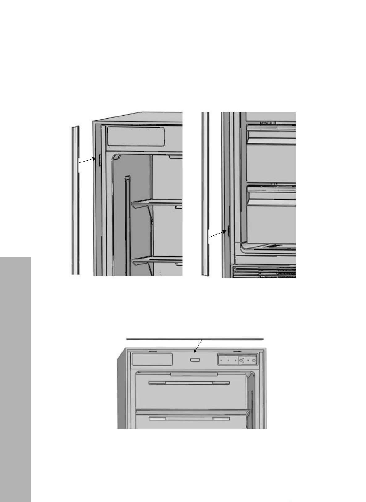
47
INSTALLATION
ATTACHING THE TRIM PIECES
• Attach the cabinet side trim pieces (page 25, Item No. 2) onto the refrigerator or freezer,
covering the cabinet mounting brackets as shown below.
!"#$%&'#(%)*
! !
%$"
"
744)6-/*2(4-.(+.6%0)4/F.(5)04'(
•! A>>3@7">78"2958"@10294;"?3:>2"`>:9."KM:49>M:8"2958"=>8."E0#a"04>0">78":9;7>g18K>"@0448@>904"/:3@P8>2<"
+
+
+
+
+
!
•! A>>3@7">78"M??8:"@10294;"?3:>"`>:9."KM:49>M:8">0?"=>8."E0!a"04>0">78"M??8:"@0448@>904"/:3@P8><! "
• Attach the cabinet top trim (page 25, Item No. 1) onto the refrigerator or freezer,
covering the cabinet mounting brackets as shown below.
!"#$%&'#(%)*! !
%$"
"
744)6-/*2(4-.(+.6%0)4/F.(5)04'(
•! A>>3@7">78"2958"@10294;"?3:>2"`>:9."KM:49>M:8"2958"=>8."E0#a"04>0">78":9;7>g18K>"@0448@>904"/:3@P8>2<"
+
+
+
+
+
!
•! A>>3@7">78"M??8:"@10294;"?3:>"`>:9."KM:49>M:8">0?"=>8."E0!a"04>0">78"M??8:"@0448@>904"/:3@P8><! "
Attaching the Trim Pieces
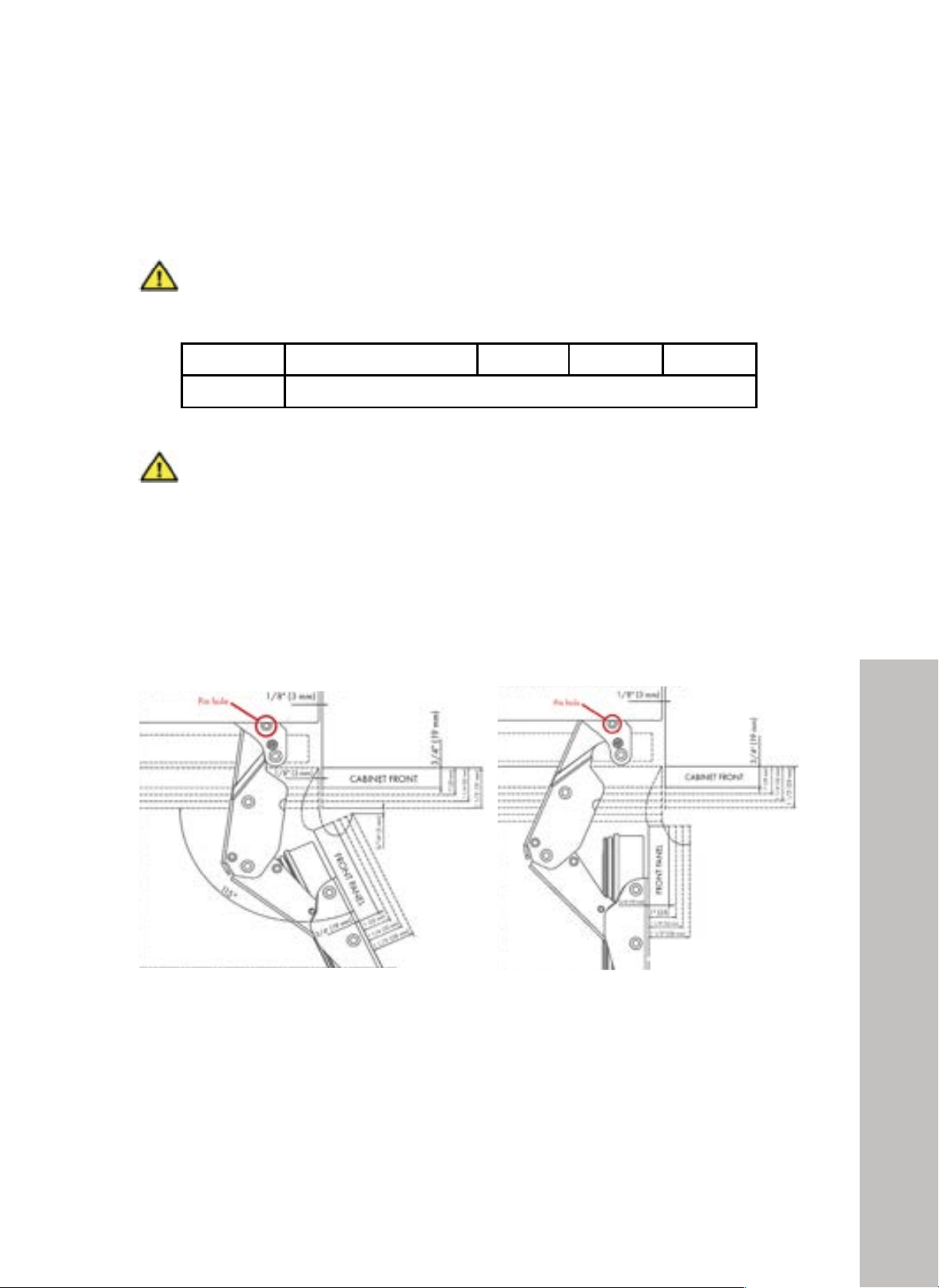
48
INSTALLATION
PANEL PREPARATION
This section contains information about preparing the panel and mounting them to the product.
WARNING
Maximum weights of the panel to be mounted to the product are as follows.
CATEGORY RBCFVL-18/RBCFVR-18 RBCFV-24 RBCRV-24 RBCRV-30
Weight 66 lb (30 kg)
WARNING
CHOOSING THE DOOR THICKNESS
The door(s) of your refrigerator can open by 115° maximum. If the door is going to open to this
degree, you can choose the following thickness levels depending on your door panels:
• If the door thickness is more than 1 1/2" (38 mm), the door should not open more than
90°. You must use a limiting pin on the hinge.
Door Panel Preparation
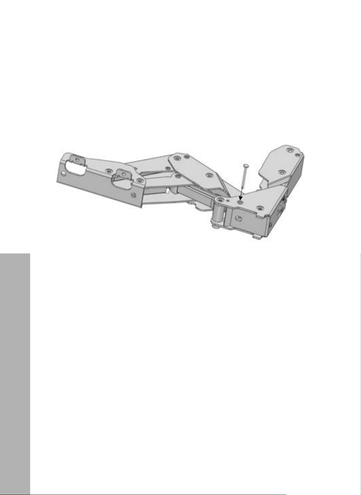
49
Door Panel Preparation
INSTALLATION
LIMITING PINS
• To limit the opening degree of your door to 90°, insert one 90° limiting pin (page 26,
Item No. 17) into the hole on the bottom hinge outlined in the images on the previous page.
• The 90° limit pin (Item No. 17) is located in the mounting part kit of the drawer box.
• The pin must be fully seated in the bracket or the door will not close properly.
!"#$%&'#(%)*! !
%&"
"
!
!
!
!
!
!
!
!
!
!
•! ]0M"@34"19.9>">78"0?8494;"58;:88"0K"-0M:"500:">0"*+f"=K"-0M"L34>"
•! *+!19.9>"?94"`9>8."E0<!(a"92"10@3>85"94">78".0M>94;"?3:>"P9>"0K">78"5:3L8:"/0_<" " " " " " "
•! I94".M2>"/8"KM11-"283>85"94">78"/:3@P8>"0:">78"500:"L911"40>"@1028"?:0?8:1-<" " " " " " " " " " " " " " " " " " " " "
!
!
!
!
!
!
!
!
!
!
!
!
!
!
!
!
!
!
!
!
!
!
!
!
!
!
!
!
!
!
!
!
!
!
!
!
!
!
!
!
!
!
!
!
*+
!
19.9>"?94"270M15"/8"9428:>85">0"M??8:"794;8"345"10L8:"794;8"
• One 90° limit pin should be inserted into upper hinge and one should be inserted into the
lower hinge.
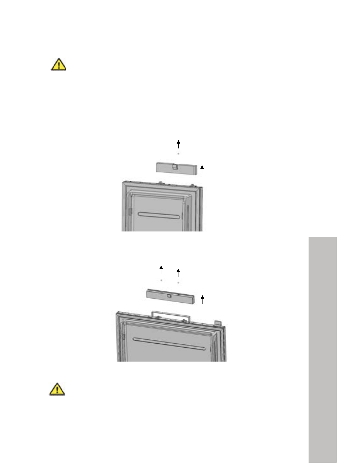
50
Door Panel Preparation
INSTALLATION
WARNING
REMOVING THE DOOR BRACKET COVERS
• Remove 2 Phillips-head screws to take out the upper bracket trim cover and cover mounting
bracket; set aside.
RBCFVL-18/RBCFVR-18/RBCFV-24/RBCRV-24
!"#$%&'#(%)*! !
%'"
"
!
:.#%F/*2(4-.(#.6-)*/'#(@%F.0'(
•! D8.0Q8"2@:8L2">0">3P8"0M>">78">0?"734;8:"/:3@P8>"@0Q8:<"
+
+
+
"
"
"
"
"
"
"
"
"
"
"
"
"
"
"
"
"
"
"
"
"
"
"
"
! !"#$%$&'(
678:8"92"3".3;48>"04">78">0?"734;8:"/:3@P8>"@0Q8:<"6792"92"3"KM4@>90431"?3:>"K0:">78"0?8:3>904"0K">78"?:05M@><" "
=>"270M15"40>"/8"@04KM285"L9>7">78"10L"734;8:"/:3@P8>"@0Q8:<"
"
!
!
!
!
!
!
!
!
"
#$%&'()*(+!
"*$,-'()*(+!
"*
$./'()*(+!
"#
$./'()*(+!
!
!
RBCRV-30
!"#$%&'#(%)*! !
%'"
"
!
:.#%F/*2(4-.(#.6-)*/'#(@%F.0'(
•! D8.0Q8"2@:8L2">0">3P8"0M>">78">0?"734;8:"/:3@P8>"@0Q8:<"
+
+
+
"
"
"
"
"
"
"
"
"
"
"
"
"
"
"
"
"
"
"
"
"
"
"
"
! !"#$%$&'(
678:8"92"3".3;48>"04">78">0?"734;8:"/:3@P8>"@0Q8:<"6792"92"3"KM4@>90431"?3:>"K0:">78"0?8:3>904"0K">78"?:05M@><" "
=>"270M15"40>"/8"@04KM285"L9>7">78"10L"734;8:"/:3@P8>"@0Q8:<"
"
!
!
!
!
!
!
!
!
"
#$%&'()*(+!
"*$,-'()*(+!
"*
$./'()*(+!
"#
$./'()*(+!
!
!
WARNING
There is a magnet in the mounting bracket trim cover. This is a functional part for
the operation of the product.
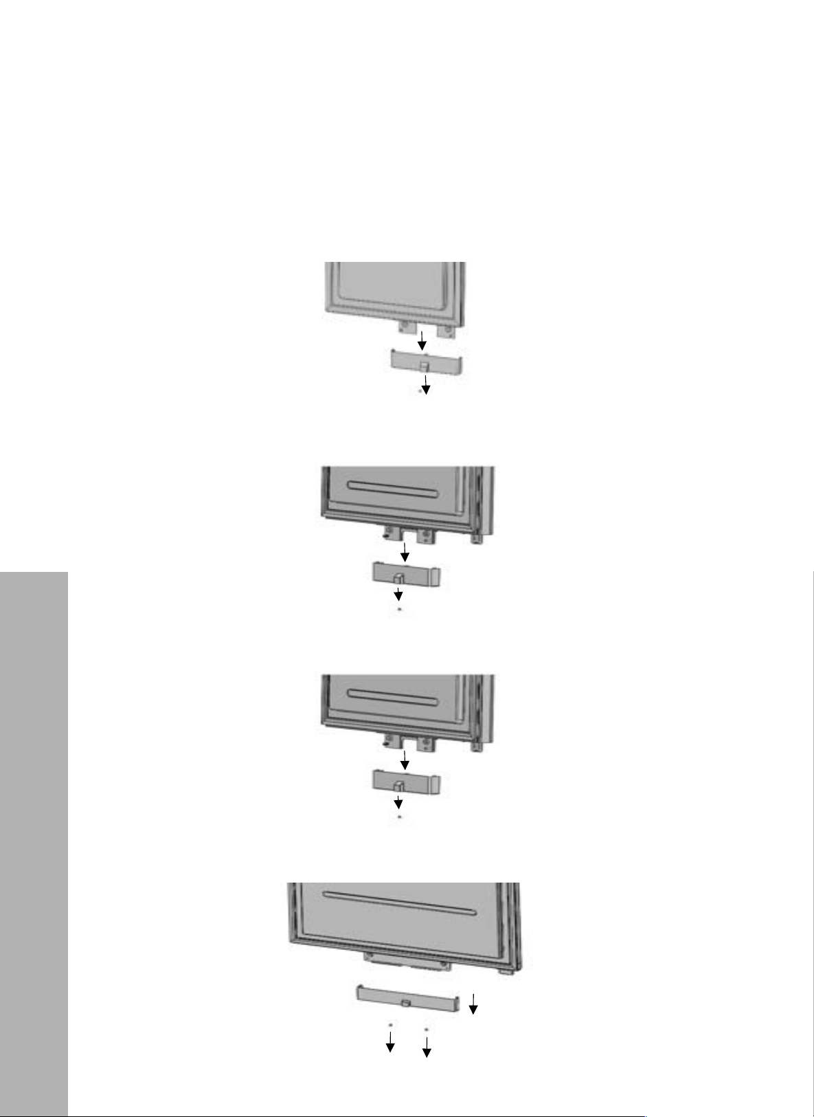
51
Door Panel Preparation
INSTALLATION
REMOVING THE DOOR BRACKET COVERS
• Remove 2 Phillips-head screws to take out the lower cover mounting bracket; set aside.
RBCFVL-18/RBCFVR-18
!"#$%&'#(%)*! !
%("
"
•! D8.0Q8"2@:8L">0">3P8"0M>">78"10L"734;8:"/:3@P8>"@0Q8:<"
!
(
(
(
(
(
(
(
(
(
"
"
"
"
"
"
"
"
"
"
"
"
"
"
"
"
"
"
"
"
"
"
"
"*
$,-'()*(+!
6GR#%U=EG=A"
6
BR#%U=EG=A"
"
6
BR$+U=EG=A"
RBCFV-24
!"#$%&'#(%)*! !
%("
"
•! D8.0Q8"2@:8L">0">3P8"0M>">78"10L"734;8:"/:3@P8>"@0Q8:<"
!
(
(
(
(
(
(
(
(
(
"
"
"
"
"
"
"
"
"
"
"
"
"
"
"
"
"
"
"
"
"
"
"
"*
$,-'()*(+!
6GR#%U=EG=A"
6
BR#%U=EG=A"
"
6
BR$+U=EG=A"
RBCRV-24
!"#$%&'#(%)*! !
%("
"
•! D8.0Q8"2@:8L">0">3P8"0M>">78"10L"734;8:"/:3@P8>"@0Q8:<"
!
(
(
(
(
(
(
(
(
(
"
"
"
"
"
"
"
"
"
"
"
"
"
"
"
"
"
"
"
"
"
"
"
"*
$,-'()*(+!
6GR#%U=EG=A"
6
BR#%U=EG=A"
"
6
BR$+U=EG=A"
RBCRV-30
!"#$%&'#(%)*! !
%("
"
•! D8.0Q8"2@:8L">0">3P8"0M>">78"10L"734;8:"/:3@P8>"@0Q8:<"
!
(
(
(
(
(
(
(
(
(
"
"
"
"
"
"
"
"
"
"
"
"
"
"
"
"
"
"
"
"
"
"
"
"*
$,-'()*(+!
6GR#%U=EG=A"
6
BR#%U=EG=A"
"
6
BR$+U=EG=A"
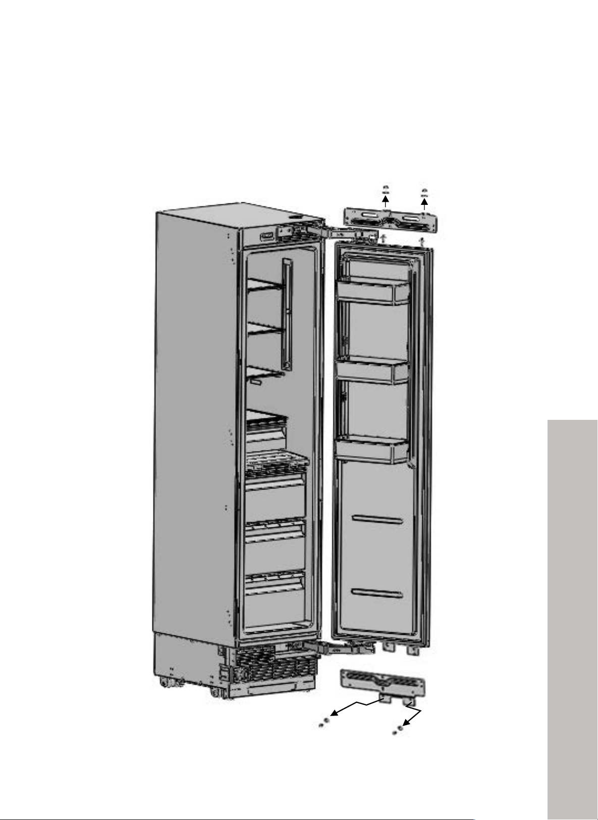
52
Door Panel Preparation
INSTALLATION
REMOVING THE DOOR PANEL - ADJUSTMENT BRACKETS (RBCFVL-18/RBCFVR-18)
• Using a drill or socket wrench, remove the bolts securing the upper and lower door panel
hanger brackets from the door.
!"#$%&'#(%)*
! !
%)"
"
!
:.#%F/*2(4-.(5)*.&G)+JC'4#.*4(#.6-)*/'#'(%*(4-.(0.A0/2.0)4%0(
!
•! D8.0Q8">78"M??8:"345"10L8:"35VM2>94;".8@73492."3228./1982"K:0.">78"500:<"
"
"
"
"
"
"
"
"
"
"
"
"
"
"
"
"
"
"
"
"
"
!
!
!
!
!
!
!
!
!
!
!
!
!
!
!
!
!
!
!
!
!
!
!
!
!
!
!
!
!
!
!
!
!
!
!
!
!
!
!
!
!
!
!
!
!
!
!
!
!
!
!
!
"
*$,-'()*(+!
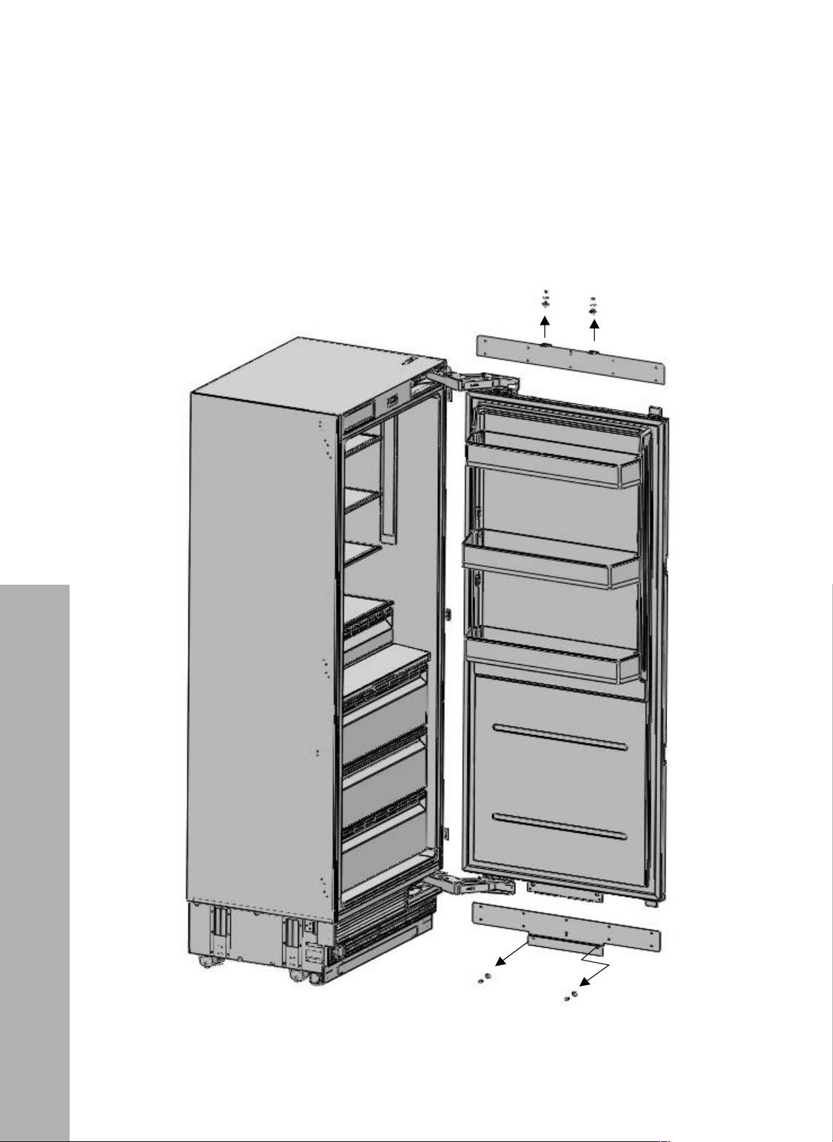
53
Door Panel Preparation
INSTALLATION
REMOVING THE DOOR PANEL - ADJUSTMENT BRACKETS
(RBCFV-24/RBCRV-24/RBCRV-30)
• Using a drill or socket wrench, remove the bolts securing the upper and lower door panel
hanger brackets from the door.
!"#$%&'#(%)*! !
%*"
"
!
!
!
!
!
!
!
!
!
"*$./'()*(+
!
"#$./'()*(+!
"#$%&'()*(+!
!"
#$%&'("')!
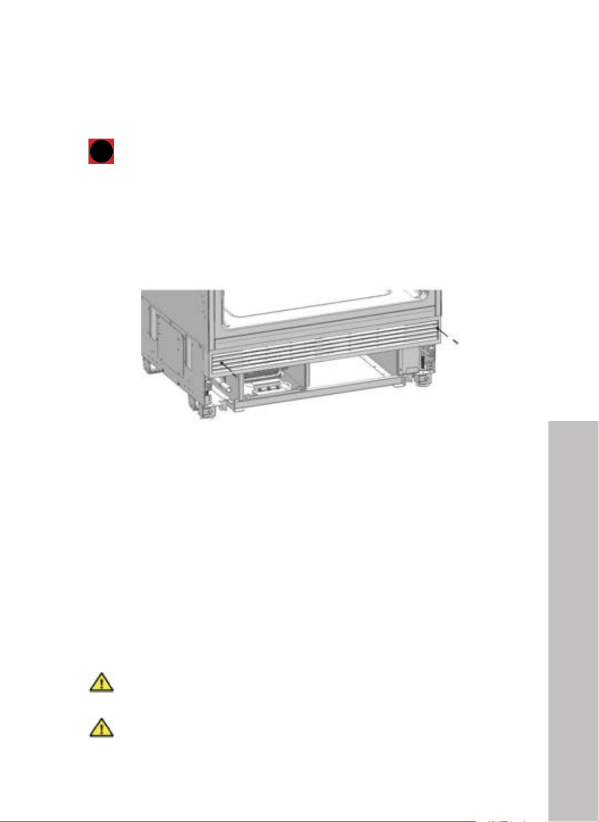
54
Door Panel Preparation
PREPARING DOOR PANELS
i
You must take the dimensions on the following pages into account when
positioning the door panel hanger brackets on the panel. When pre-drilling
holes, you can use the provided door panel preparation template (page
27, Item No. 18) to align the panel brackets in the correct location. Use
care to not drill too deep when pre-drilling.
INFO
!"#$%&'#(%)*! !
&!"
"
!
">>2=573:&>56&<AA68&J63>&5/06&A28>&
!! Y5/"#"5>2/[5".1"-..->=".=/"6II/2"Z/:."=1;/"I-2.?"
"
+
+
+
!
Handle connection holes must be adjusted according to the handle orientation
you plan to use in your kitchen design.
WARNING
NOTE: Minimum thickness of the side walls is 5/8" (16 mm). The minimum
thickness of the doors to be attached to the product must be 3/4" (19 mm).
For a 25" (635 mm) flush inset depth, the maximum door panel thickness is
15/16" (24 mm).
WARNING
INSTALLATION
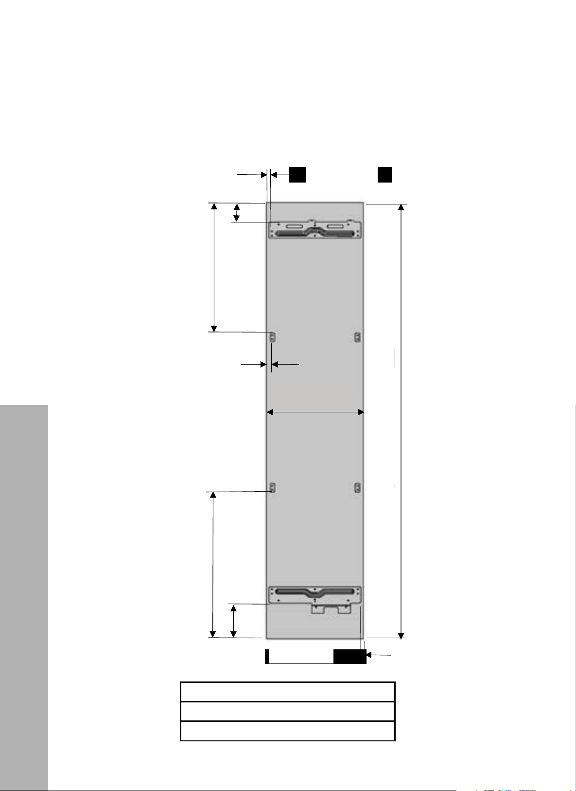
55
Door Panel Preparation
INSTALLATION
PREPARING THE FREEZER DOOR PANEL
RBCFVL-18/RBCFVR-18 FREEZER DOOR PANEL DIMENSIONS
!"#$%&'#(%)*! !
&!"
"
+
!
!
!
!
!
!
!
!
!
!
!
!
!
!
!
!
!
!
!
!
!
!
!
!
!
!
!
!
!
!
!
!
!
!
!
!
!
!
!
!
!
"! +J'LH#J'$);&&')QJ#&J#);HF$L=H&L)
+
+ ++++++++
+
+
!
./012345+ 678!"9:;7:*+ 678	:;7:*+ 678	:;7:*+ 6<8,(9:;7:*+
>>+ #$!+?+&(,(+ '(,+?+&(,(+ '(,+?+&(,(+ %$'+?+&(,(+
@ABC+ !%+,-#+?+%)+!$-!'+ &,+,-#+?+%)+!$-!'+ &,+,-#+?+%)+!$-!'+ &)+,-#+?+&)+!$-!'+
GH-) I/G-445
!
6)GH-) I/3J2K445!
"!
KJ)G0HGL.) /-161445!
-L)KH3) I/L3620445!
"!
L)GH-I/GL020445!
"!
-6)KH3) I/L1L20445!
"!
KHG1) I/G32-445!
GH-) I/G-445!
"!
"*
$,-'()*(+!
"*$./'()*(+
!
"
#$./'()*(+!
"#$%&'()*(+
!
G)GHGL) I/-K445!
34N) M)36)6D4X>E76FF@!
67N) M)3C)6D4N>BAEFF@!
6)GH-) I/3J2K445!
"!
) -B)6D4X) >4A-FF@!
G)GHGL) I/-K445
!
"!
KJ)G0HGL.) /-161445!
-6)KH3) I/L1L20445!
"!
-L)KH3) I/L3620445!
"!
KHG1) I/G32-445!
L)GH-) I/GLL20445!
"!
!"#$%&'#(%)*! !
#%"
"
:.#%F/*2(#%C*4/*2(5)04'(/*(4-.(+0)B.0(6%#5)04#.*4(
%
"
"
"
"
"
"
"
"
"
"
"
"
+
!
!
!
!
!
!
!
!
!
!
!
!
!
!
!
!
!
!
!
!
!
!
!
!
1&)
]"'#)L"F$)
^K$Q)
-.)
34)
67)
P$F"'?)
-)
2L#H,#HK)<'"Q?$#)
*4V7a) ) !'bcL,Q&"#HL%)
.)
.)
.)
)
3)
2L#H)#HK)<'"Q?$#)=Q'$G=)"L;);&G$:=)
8.d5E7)
.)
.)
.)
)
6)
]&=H#H&L)";SJ=#F$L#)SH%)
]^)
-)
-)
-)
)
4)
!&T$')RJ'LH#J'$);&&')<'"Q?$#)
"<=)
,)
3)
3)
)
A)
*'J==)G"=I$')I$";)
84d-3)
,)
3)
3)
)
E)
/'"Q?$#)RJ'LH#J'$);&&')
*-V7a) ) !'bcL,Q&"#HL%)
,)
3)
3)
)
B)
!&JL#$')=JL?)I$";)=Q'$G)
^*49-4)
,)
4)
4)
)
.)
*'J==)G"=I$')I$";)
84d-3)
4)
4)
4)
)
C)
^eJ"'$)G"=I$')
*-V7a) ) !'bcL,Q&"#HL%)
4)
4)
4)
)
-7)
!$L#$')F&JL#HL%)<'"Q?$#)
*-V7a) ) !'bcL,Q&"#HL%)
4)
4)
4)
)
--)
!&JL#$')=JL?)I$";)=Q'$G)
^*49-4)
.)
.)
.)
)
-3)
/'"Q?$#)RJ'LH#J'$) )
*-V7a) ) !'bcL,Q&"#HL%)
.)
.)
.)
)
-6)
!&JL#$')=JL?)I$";)=Q'$G)
^*)849-4)
-E)
-E)
-E)
)
-4)
*'J==)G"=I$')I$";)
84d-3)
-E)
-E)
-E)
)
-A)
!&JL#$')=JL?)I$";)=Q'$G)))
^*)849-4)
-E)
37)
37)
+J'LH#J'$);&&')I"L%$')<'"Q?$#)
-E)
2H')T$L#)IHL%$)K"'#)
2/^)
,)
-)
-)
O&&')&K$LHL%);H'$Q#H&L)QI"L%$)
-B)
C7f:HFH#)KHL)
g4)
3)
3)
3)
O&&')C7f&K$LHL%)J=$)
!! 2L#H)#HK)<'"Q?$#)=Q'$G=) )
!! ;&G$:="
!! !&JL#$')=JL?)I$";)=Q'$G)
^K$Q)M)^*)849-4)
+H9HL%)#I$)Q"<HL)"L;)
RJ'LH#J'$);&&')
>G&&;)K"'#@)
!! *'J==)G"=I$')I$";)=Q'$G"
^K$Q)M)849-3)
+H9HL%)P$R'H%$'"#&')
^JQI)"=)Q"<HL$#)"L;);&&')
>K'$==)K"'#@)
!"#$%&'#(%)*! !
#%"
"
:.#%F/*2(#%C*4/*2(5)04'(/*(4-.(+0)B.0(6%#5)04#.*4(
%
"
"
"
"
"
"
"
"
"
"
"
"
+
!
!
!
!
!
!
!
!
!
!
!
!
!
!
!
!
!
!
!
!
!
!
!
!
1&)
]"'#)L"F$)
^K$Q)
-.)
34)
67)
P$F"'?)
-)
2L#H,#HK)<'"Q?$#)
*4V7a) ) !'bcL,Q&"#HL%)
.)
.)
.)
)
3)
2L#H)#HK)<'"Q?$#)=Q'$G=)"L;);&G$:=)
8.d5E7)
.)
.)
.)
)
6)
]&=H#H&L)";SJ=#F$L#)SH%)
]^)
-)
-)
-)
)
4)
!&T$')RJ'LH#J'$);&&')<'"Q?$#)
"<=)
,)
3)
3)
)
A)
*'J==)G"=I$')I$";)
84d-3)
,)
3)
3)
)
E)
/'"Q?$#)RJ'LH#J'$);&&')
*-V7a) ) !'bcL,Q&"#HL%)
,)
3)
3)
)
B)
!&JL#$')=JL?)I$";)=Q'$G)
^*49-4)
,)
4)
4)
)
.)
*'J==)G"=I$')I$";)
84d-3)
4)
4)
4)
)
C)
^eJ"'$)G"=I$')
*-V7a) ) !'bcL,Q&"#HL%)
4)
4)
4)
)
-7)
!$L#$')F&JL#HL%)<'"Q?$#)
*-V7a) ) !'bcL,Q&"#HL%)
4)
4)
4)
)
--)
!&JL#$')=JL?)I$";)=Q'$G)
^*49-4)
.)
.)
.)
)
-3)
/'"Q?$#)RJ'LH#J'$) )
*-V7a) ) !'bcL,Q&"#HL%)
.)
.)
.)
)
-6)
!&JL#$')=JL?)I$";)=Q'$G)
^*)849-4)
-E)
-E)
-E)
)
-4)
*'J==)G"=I$')I$";)
84d-3)
-E)
-E)
-E)
)
-A)
!&JL#$')=JL?)I$";)=Q'$G)))
^*)849-4)
-E)
37)
37)
+J'LH#J'$);&&')I"L%$')<'"Q?$#)
-E)
2H')T$L#)IHL%$)K"'#)
2/^)
,)
-)
-)
O&&')&K$LHL%);H'$Q#H&L)QI"L%$)
-B)
C7f:HFH#)KHL)
g4)
3)
3)
3)
O&&')C7f&K$LHL%)J=$)
!! 2L#H)#HK)<'"Q?$#)=Q'$G=) )
!! ;&G$:="
!! !&JL#$')=JL?)I$";)=Q'$G)
^K$Q)M)^*)849-4)
+H9HL%)#I$)Q"<HL)"L;)
RJ'LH#J'$);&&')
>G&&;)K"'#@)
!! *'J==)G"=I$')I$";)=Q'$G"
^K$Q)M)849-3)
+H9HL%)P$R'H%$'"#&')
^JQI)"=)Q"<HL$#)"L;);&&')
>K'$==)K"'#@)
18 models:
17 3/4" (451 mm)
24" Models: 23 3/4" (603 mm)
30" Models: 29 3/4" (756 mm)
11/16" (18 mm)
11/16" (18 mm)
3/8" (10 mm)
3 3/8" (85 mm)
23 7/16" (595 mm)
3 3/8" (85 mm)
23 7/16" (595 mm)
79 15/16" (2030 mm)
79 15/16" (2030 mm)
6 7/8" (175 mm)
26 15/16" (684 mm)
3/8" (10 mm)
3/8" (10 mm)
3/8" (10 mm)
6 7/8" (175 mm)
26 15/16" (684 mm)
Confidential
29
Open the freezer com part m ent door and rem ove the m ounting boxes and docum ents in the
cris per.
√
Conference
No Part name spec 76 91 92
1 Furniture door preparation template paper 1 1 1
2 Anti tip bracket T4. 0, Zn- coating 2 2 2
3 Dowel - 8 8 8
4 Anti tip bracket screw s M8*L60 8 8 8
5 Position adjustment jig PS 1 1 1
6 90° limiting pins sus 2 2 -
7 Freezer furni ture door adjustment washer abs 9 9 9
8 Screw freezer door hanger bracket ST4. 8*16, round head screw 3 3 3
9 Freezer door hanger bracket T1. 0, Cr+zn- coating 3 3 3
10
Screw f reezer furniture door
hanger brac ket
ST4x14, counter sunk head
screw 18 18 18
11 Screw cabinet connecting bracket M4*12, truss washer head 16 16 16
Category TRF- 76BINFIA TRF- 91BINFIA TRF- 92BINFIA
Abbreviation. 76 91 92
1 2 3 4 5 6
8
7
9
10
14
15
18
16
17
11
12
13
PANEL DIMENSIONS
RBCFVL-18/RBCFVR-18
17 3/4" x 79 15/16" (451 mm x 2030 mm)
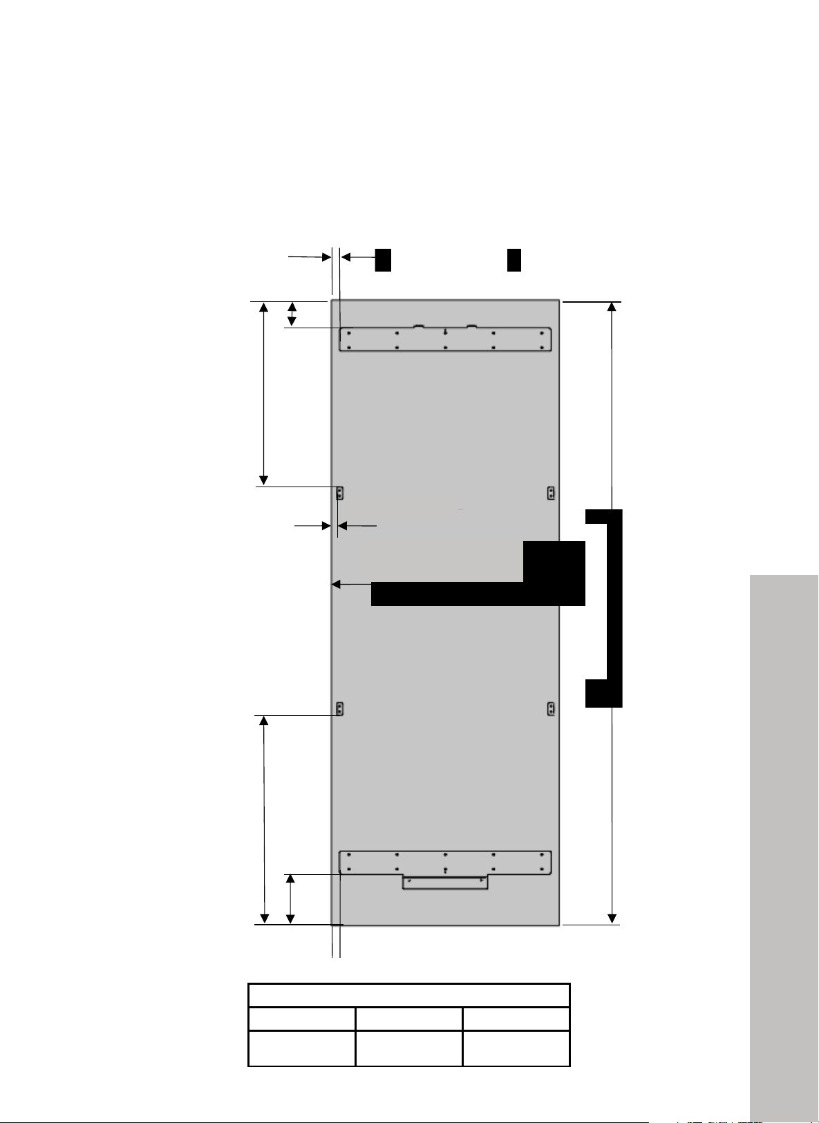
56
Door Panel Preparation
INSTALLATION
PREPARING THE FREEZER & REFRIGERATOR DOOR PANEL
RBCFV-24/RBCRV-24/RBCRV-30 FREEZER & REFRIGERATOR
DOOR PANEL DIMENSIONS
!"#$%&'#(%)*! !
&!"
"
+
!
!
!
!
!
!
!
!
!
!
!
!
!
!
!
!
!
!
!
!
!
!
!
!
!
!
!
!
!
!
!
!
!
!
!
!
!
!
!
!
!
"! +J'LH#J'$);&&')QJ#&J#);HF$L=H&L)
+
+ ++++++++
+
+
!
./012345+ 678!"9:;7:*+ 678	:;7:*+ 678	:;7:*+ 6<8,(9:;7:*+
>>+ #$!+?+&(,(+ '(,+?+&(,(+ '(,+?+&(,(+ %$'+?+&(,(+
@ABC+ !%+,-#+?+%)+!$-!'+ &,+,-#+?+%)+!$-!'+ &,+,-#+?+%)+!$-!'+ &)+,-#+?+&)+!$-!'+
GH-) I/G-445
!
6)GH-) I/3J2K445!
"!
KJ)G0HGL.) /-161445!
-L)KH3) I/L3620445!
"!
L)GH-I/GL020445!
"!
-6)KH3) I/L1L20445!
"!
KHG1) I/G32-445!
GH-) I/G-445!
"!
"*
$,-'()*(+!
"*$./'()*(+
!
"
#$./'()*(+!
"#$%&'()*(+
!
G)GHGL) I/-K445!
34N) M)36)6D4X>E76FF@!
67N) M)3C)6D4N>BAEFF@!
6)GH-) I/3J2K445!
"!
) -B)6D4X) >4A-FF@!
G)GHGL) I/-K445
!
"!
KJ)G0HGL.) /-161445!
-6)KH3) I/L1L20445!
"!
-L)KH3) I/L3620445!
"!
KHG1) I/G32-445!
L)GH-) I/GLL20445!
"!
!"#$%&'#(%)*! !
#%"
"
:.#%F/*2(#%C*4/*2(5)04'(/*(4-.(+0)B.0(6%#5)04#.*4(
%
"
"
"
"
"
"
"
"
"
"
"
"
+
!
!
!
!
!
!
!
!
!
!
!
!
!
!
!
!
!
!
!
!
!
!
!
!
1&)
]"'#)L"F$)
^K$Q)
-.)
34)
67)
P$F"'?)
-)
2L#H,#HK)<'"Q?$#)
*4V7a) ) !'bcL,Q&"#HL%)
.)
.)
.)
)
3)
2L#H)#HK)<'"Q?$#)=Q'$G=)"L;);&G$:=)
8.d5E7)
.)
.)
.)
)
6)
]&=H#H&L)";SJ=#F$L#)SH%)
]^)
-)
-)
-)
)
4)
!&T$')RJ'LH#J'$);&&')<'"Q?$#)
"<=)
,)
3)
3)
)
A)
*'J==)G"=I$')I$";)
84d-3)
,)
3)
3)
)
E)
/'"Q?$#)RJ'LH#J'$);&&')
*-V7a) ) !'bcL,Q&"#HL%)
,)
3)
3)
)
B)
!&JL#$')=JL?)I$";)=Q'$G)
^*49-4)
,)
4)
4)
)
.)
*'J==)G"=I$')I$";)
84d-3)
4)
4)
4)
)
C)
^eJ"'$)G"=I$')
*-V7a) ) !'bcL,Q&"#HL%)
4)
4)
4)
)
-7)
!$L#$')F&JL#HL%)<'"Q?$#)
*-V7a) ) !'bcL,Q&"#HL%)
4)
4)
4)
)
--)
!&JL#$')=JL?)I$";)=Q'$G)
^*49-4)
.)
.)
.)
)
-3)
/'"Q?$#)RJ'LH#J'$) )
*-V7a) ) !'bcL,Q&"#HL%)
.)
.)
.)
)
-6)
!&JL#$')=JL?)I$";)=Q'$G)
^*)849-4)
-E)
-E)
-E)
)
-4)
*'J==)G"=I$')I$";)
84d-3)
-E)
-E)
-E)
)
-A)
!&JL#$')=JL?)I$";)=Q'$G)))
^*)849-4)
-E)
37)
37)
+J'LH#J'$);&&')I"L%$')<'"Q?$#)
-E)
2H')T$L#)IHL%$)K"'#)
2/^)
,)
-)
-)
O&&')&K$LHL%);H'$Q#H&L)QI"L%$)
-B)
C7f:HFH#)KHL)
g4)
3)
3)
3)
O&&')C7f&K$LHL%)J=$)
!! 2L#H)#HK)<'"Q?$#)=Q'$G=) )
!! ;&G$:="
!! !&JL#$')=JL?)I$";)=Q'$G)
^K$Q)M)^*)849-4)
+H9HL%)#I$)Q"<HL)"L;)
RJ'LH#J'$);&&')
>G&&;)K"'#@)
!! *'J==)G"=I$')I$";)=Q'$G"
^K$Q)M)849-3)
+H9HL%)P$R'H%$'"#&')
^JQI)"=)Q"<HL$#)"L;);&&')
>K'$==)K"'#@)
!"#$%&'#(%)*! !
#%"
"
:.#%F/*2(#%C*4/*2(5)04'(/*(4-.(+0)B.0(6%#5)04#.*4(
%
"
"
"
"
"
"
"
"
"
"
"
"
+
!
!
!
!
!
!
!
!
!
!
!
!
!
!
!
!
!
!
!
!
!
!
!
!
1&)
]"'#)L"F$)
^K$Q)
-.)
34)
67)
P$F"'?)
-)
2L#H,#HK)<'"Q?$#)
*4V7a) ) !'bcL,Q&"#HL%)
.)
.)
.)
)
3)
2L#H)#HK)<'"Q?$#)=Q'$G=)"L;);&G$:=)
8.d5E7)
.)
.)
.)
)
6)
]&=H#H&L)";SJ=#F$L#)SH%)
]^)
-)
-)
-)
)
4)
!&T$')RJ'LH#J'$);&&')<'"Q?$#)
"<=)
,)
3)
3)
)
A)
*'J==)G"=I$')I$";)
84d-3)
,)
3)
3)
)
E)
/'"Q?$#)RJ'LH#J'$);&&')
*-V7a) ) !'bcL,Q&"#HL%)
,)
3)
3)
)
B)
!&JL#$')=JL?)I$";)=Q'$G)
^*49-4)
,)
4)
4)
)
.)
*'J==)G"=I$')I$";)
84d-3)
4)
4)
4)
)
C)
^eJ"'$)G"=I$')
*-V7a) ) !'bcL,Q&"#HL%)
4)
4)
4)
)
-7)
!$L#$')F&JL#HL%)<'"Q?$#)
*-V7a) ) !'bcL,Q&"#HL%)
4)
4)
4)
)
--)
!&JL#$')=JL?)I$";)=Q'$G)
^*49-4)
.)
.)
.)
)
-3)
/'"Q?$#)RJ'LH#J'$) )
*-V7a) ) !'bcL,Q&"#HL%)
.)
.)
.)
)
-6)
!&JL#$')=JL?)I$";)=Q'$G)
^*)849-4)
-E)
-E)
-E)
)
-4)
*'J==)G"=I$')I$";)
84d-3)
-E)
-E)
-E)
)
-A)
!&JL#$')=JL?)I$";)=Q'$G)))
^*)849-4)
-E)
37)
37)
+J'LH#J'$);&&')I"L%$')<'"Q?$#)
-E)
2H')T$L#)IHL%$)K"'#)
2/^)
,)
-)
-)
O&&')&K$LHL%);H'$Q#H&L)QI"L%$)
-B)
C7f:HFH#)KHL)
g4)
3)
3)
3)
O&&')C7f&K$LHL%)J=$)
!! 2L#H)#HK)<'"Q?$#)=Q'$G=) )
!! ;&G$:="
!! !&JL#$')=JL?)I$";)=Q'$G)
^K$Q)M)^*)849-4)
+H9HL%)#I$)Q"<HL)"L;)
RJ'LH#J'$);&&')
>G&&;)K"'#@)
!! *'J==)G"=I$')I$";)=Q'$G"
^K$Q)M)849-3)
+H9HL%)P$R'H%$'"#&')
^JQI)"=)Q"<HL$#)"L;);&&')
>K'$==)K"'#@)
18 models:
17 3/4" (451 mm)
24" Models: 23 3/4" (603 mm)
30" Models: 29 3/4" (756 mm)
11/16" (18 mm)
11/16" (18 mm)
3/8" (10 mm)
3 3/8" (85 mm)
23 7/16" (595 mm)
3 3/8" (85 mm)
23 7/16" (595 mm)
79 15/16" (2030 mm)
79 15/16" (2030 mm)
6 7/8" (175 mm)
26 15/16" (684 mm)
3/8" (10 mm)
3/8" (10 mm)
3/8" (10 mm)
6 7/8" (175 mm)
26 15/16" (684 mm)
Confidentia l
29
Open the freezer com partm ent door and rem ove the m ounting boxes and docum ents in the
cris per.
√ Conference
No Part name spec 76 91 92
1 Furni ture door preparation template paper 1 1 1
2 Anti tip bracket T4. 0, Zn- coating 2 2 2
3 Dowel - 8 8 8
4 Anti tip bracket sc rews M8*L60 8 8 8
5 Position adjustment jig PS 1 1 1
6 90° limiting pins sus 2 2 -
7 Freezer furniture door adjustment washer abs 9 9 9
8 Screw f reezer door hanger bracket ST4. 8*16, round head screw 3 3 3
9 Freezer door hanger bracket T1. 0, Cr+zn- coating 3 3 3
10
Screw freezer furniture door
hanger bracket
ST4x14, counter sunk head
screw 1
8 18 18
11 Screw cabinet connecting bracket M4*12, truss washer head 16 16 16
Category TRF- 76BINFIA TRF- 91BINFIA TRF- 92BINFIA
Abbreviation. 76 91 92
1 2 3 4 5 6
8
7
9
10
14
15
18
16
17
11
12
13
PANEL DIMENSIONS
RBCFV-24 RBCRV-24 RBCRV-30
23 3/4" x 79 15/16"
(603 mm x 2030 mm)
23 3/4" x 79 15/16"
(603 mm x 2030 mm)
29 3/4" x 29 15/16"
(756 mm x 2030 mm)
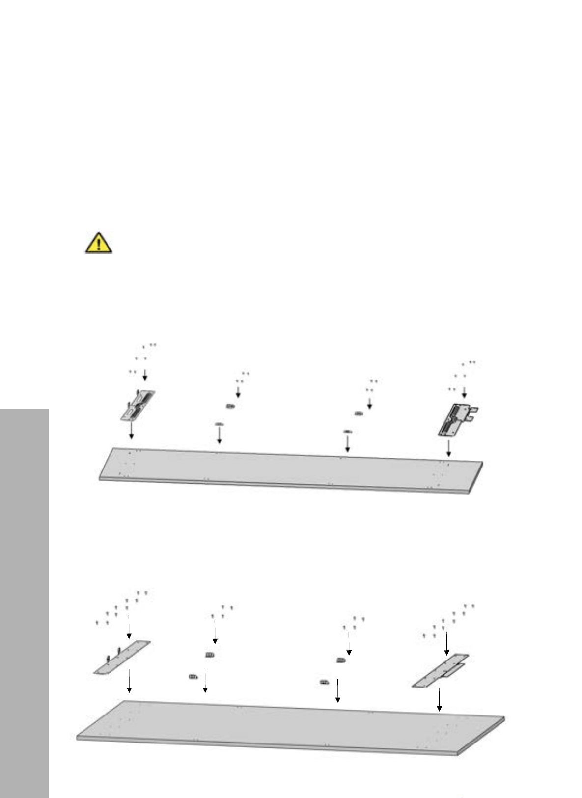
57
Door Panel Preparation
INSTALLATION
PREPARING THE REFRIGERATOR DOOR PANEL
• Secure the door panel hanger brackets removed on page 52 as shown below using the
provided screws (page 27, Item No. 15).
• You can use the door panel preparation template provided with the product to align these
parts. We recommend keeping this template for future reference.
WARNING
You must use screws suitable for the door thickness; this can vary depending on
if you opt for custom panels.
RBCFVL-18/RBCFVR-18
— 12 screws total, 6 per bracket
— 8 screws total, 4 side mounting brackets total
!"#$%&'#(%)*! !
&#"
"
!
!
!"#$%$&'(
]0M".M2>"M28"2@:8L2`9>8."E0<!&a<"2M9>3/18"K0:">78"500:">79@P4822<"
!
!
•! =42>311"@:35182"M294;">78"@79?/03:5"2@:8L2<"]0M"@34"3120"M28">78">8.?13>8"?:0Q9585"L9>7">78"
?:05M@>">0"319;4">7828"?3:>2<"=>"92":8@0..84585">0"P88?">792">8.?13>8"K0:"KM>M:8":8K8:84@8<"
!
!
!
!
!
!
!
!
!
!
!
!
!
!
!
!
!
!
!
!
!
!
!
!
!
"
"
"
"
"
"
"
!
"*$./'()*(+
!
"
#$./'()*(+!
"
#$%&'()*(+!
"*
$,-'()*(+!
RBCFV-24/RBCRV-24/RBCRV-30
— 20 screws total, 10 per bracket (2 brackets per door)
— 8 screws total, 4 brackets total (2 screws per bracket)
!"#$%&'#(%)*
! !
&#"
"
!
! !"#$%$&'(
]0M".M2>"M28"2@:8L2`9>8."E0<!&a<"2M9>3/18"K0:">78"500:">79@P4822<"
!
!
•! =42>311"@:35182"M294;">78"@79?/03:5"2@:8L2<"]0M"@34"3120"M28">78">8.?13>8"?:0Q9585"L9>7">78"
?:05M@>">0"319;4">7828"?3:>2<"=>"92":8@0..84585">0"P88?">792">8.?13>8"K0:"KM>M:8":8K8:84@8<"
!
!
!
!
!
!
!
!
!
!
!
!
!
!
!
!
!
!
!
!
!
!
!
!
!
"
"
"
"
"
"
"
!
"*$./'()*(+
!
"
#$./'()*(+!
"
#$%&'()*(+!
"*
$,-'()*(+!
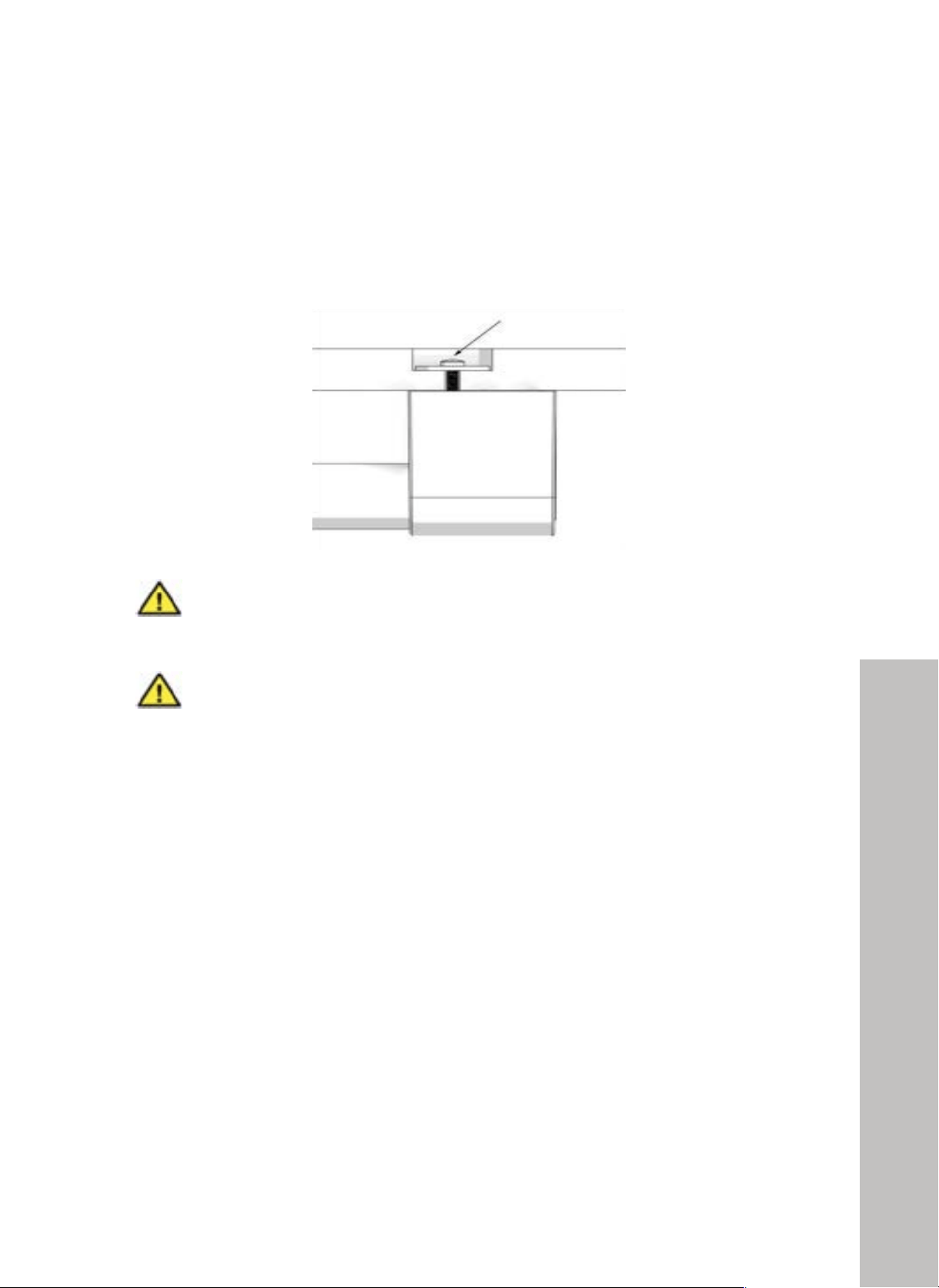
58
Door Handle Preparation
INSTALLATION
ATTACHING THE DOOR HANDLES
For both the refrigerator and freezer door handle, the provided mounting studs need to be
installed on the decorative side of the panel; fix the other side of the screw in place with a
washer and nut, and attach the handle as shown below.
WARNING
Handle connection holes must be adjusted according to the handles to be used in
kitchen design.
WARNING
NOTE: Minimum thickness of the side walls is 5/8" (16 mm). The minimum
thickness of the doors to be attached to the product must be 3/4" (19 mm). For
a 25" (635 mm) flush inset depth, the maximum door panel thickness is
15/16" (24 mm).
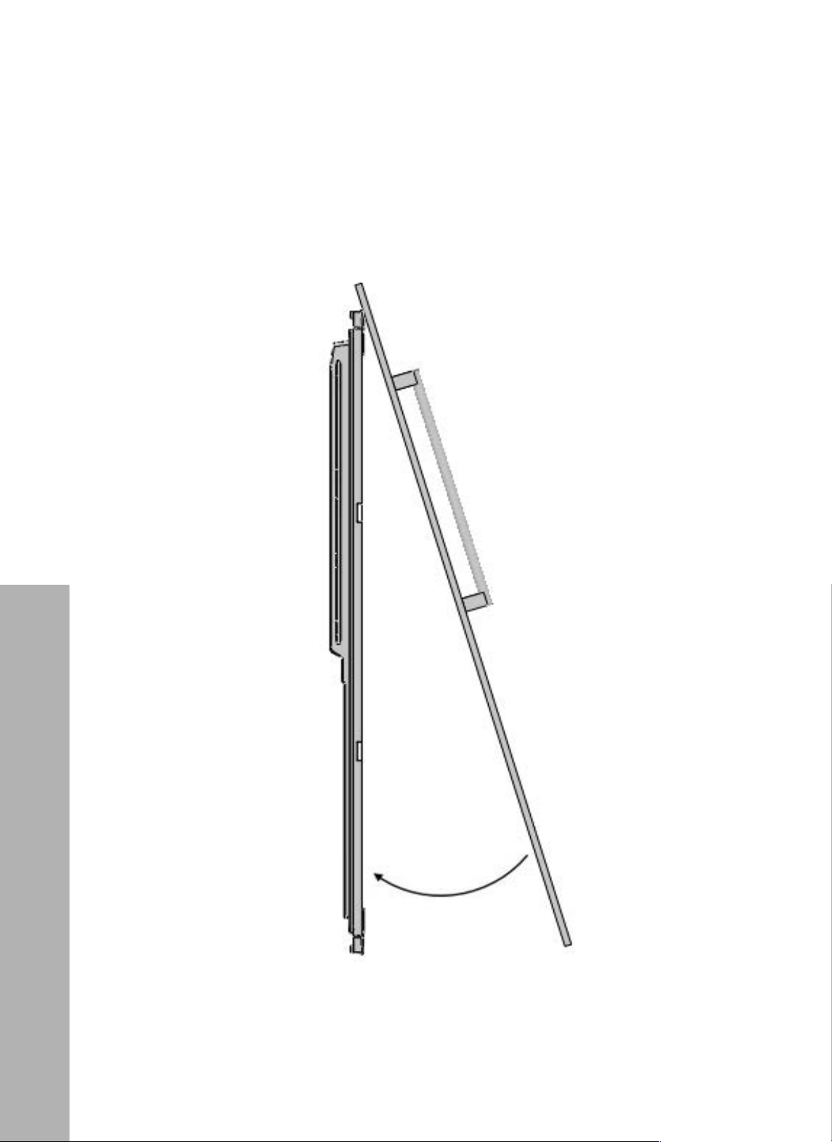
59
Door Panel Installation
INSTALLING THE DOOR PANEL
• With brackets properly installed, hang the door panel to the refrigerator or freezer door
by aligning the top door panel hanger bracket to where the upper bracket and trim
covers were removed on pages 50–52.
!"#$%&'#(%)*! !
&%"
"
3*'4)&&/*2(4-.(AC0*/4C0.(+%%0!
!
"#! $%%&'()%(*)+,-./%,-*)011-)%1)%(*)011-)
!
!
!
!
!
!
!
!
!
!
!
!
!
!
!
!
!
!
!
!
!
!
!
!
!
!
!
!
!
!
!
!
!
!
!
!
!
!
INSTALLATION
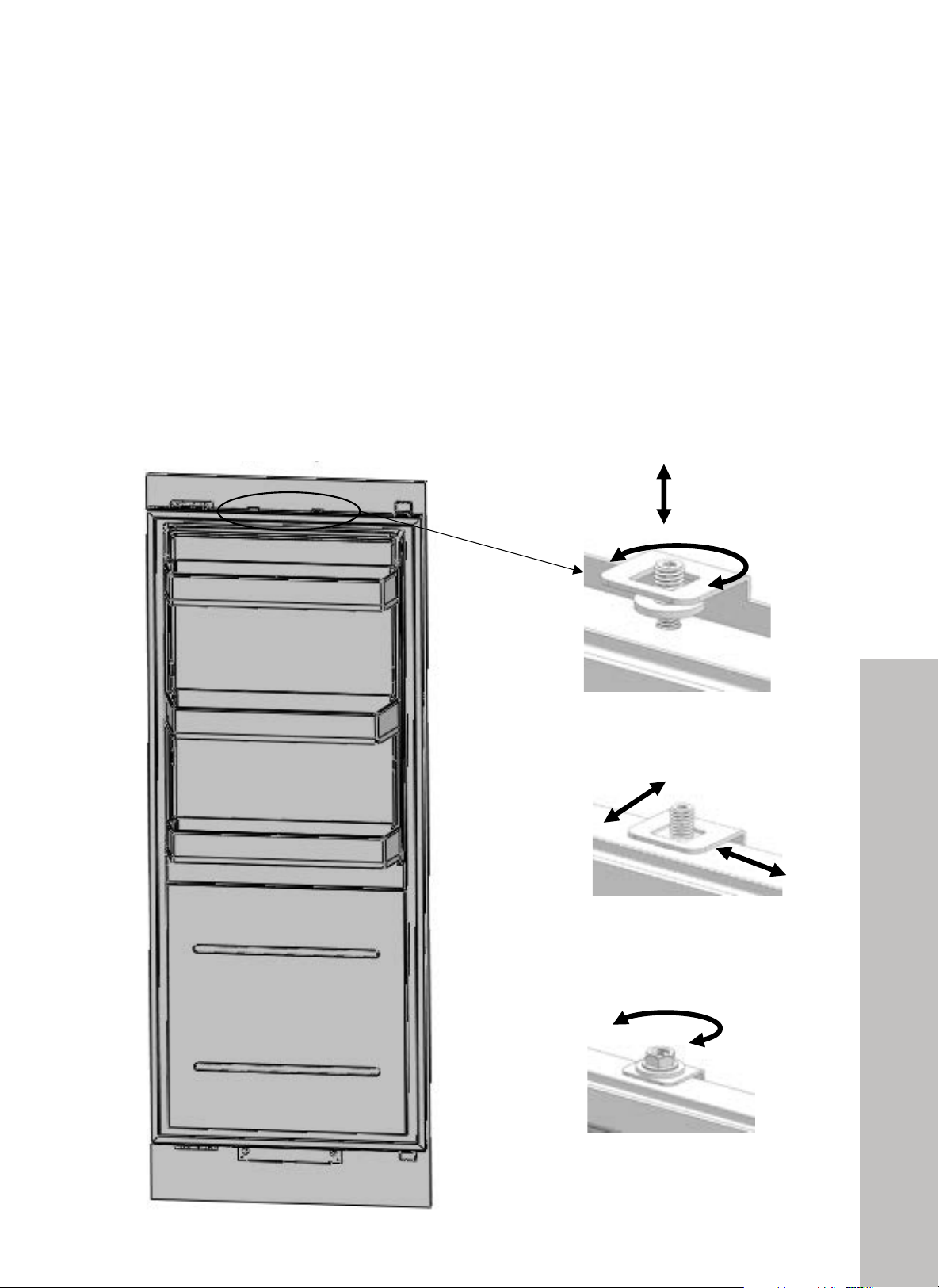
60
Door Panel Installation
INSTALLATION
ALIGNING THE DOOR WITH BOLTS
• You must position the door panel to be flush with both the appliance door and to the
cabinet cutout.
• Distances between the doors must be 3/16" (5 mm); refer to page 37 as a reminder on
how to properly align the door panels.
• To help with this, use a 1/4" - T25 Torx bit to rotate two bolts at the top refrigerator door
panel hanger bracket to perform fine adjustments, as outlined below. Secure the door
panel completely using a socket wrench.
!"#$%&'#(%)*! !
&&"
"
•! T0L">0"319;4">78"KM:49>M:8"500:"M??8:"?3:>"L9>7"/01>2<" "
+
I029>904"0K">78"GM:49>M:8"Y00:2">0">78"P9>@784"KM:49>M:8".M2>"/8"K1M27<" "
60"3@798Q8">792\"-0M"270M15"35VM2>"$Y"59:8@>904"M294;"/-">L0"K9_94;"/01>">0"?8:K0:."K948"35VM2>.84>2<"
G9:2>"0K"311\":8Q98L">78"?029>904"0K">78";:0M?85"GM:49>M:8"Y00:2"3;3942>">78"P9>@784"KM:49>M:8<" " "
Y92>34@82"/8>L884"KM:49>M:8".M2>"/8"!g)e"`$"..a\"322M.94;">73>">78"KM:49>M:8"59.8429042"3:8"@0::8@><"
" """""""""""""]0M"@34".3P8"500:"35VM2>.84>2"/3285"04">792"592>34@8<" "
!
!
!
!
M8)N)=+;>
!
O(+>&)N)A%<P)
Q'9&)N)(@D*&)
O@R@>D)9S(>@&S(')=++()<+48?'&'?C!
Up & down
Securing door
panel completely
Front & back
Left & right
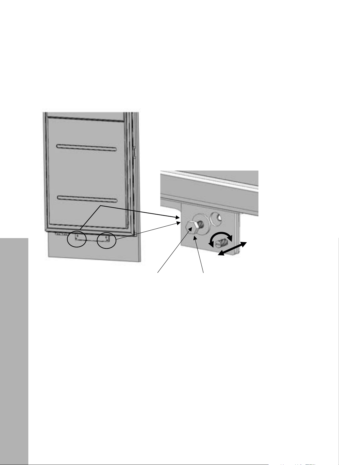
61
Door Panel Installation
INSTALLATION
ALIGNING THE REFRIGERATOR DOOR WITH BOLTS
• Perform a similar process with the bolts located at the bottom door panel hanger bracket,
as shown below. Secure the door panel completely using a flathead screwdriver.
!"#$%&'#(%)*
!
&'"
"
!
• ! T0L">0"319;4">78"KM:49>M:8"500:"10L8:"?3:>"L9>7"/01>2<"
"
"
"
+
!
!
!
!
!
!
!
!
!
!
!
!
!
!
!
!
!
!
!
!
!
!
!
!
!
!
!
!
!
!
!
!
!
!
!
!
!
!
!
!
!
!
!
!
!
Up & down
Left & right
Front & back
Securing door panel completely
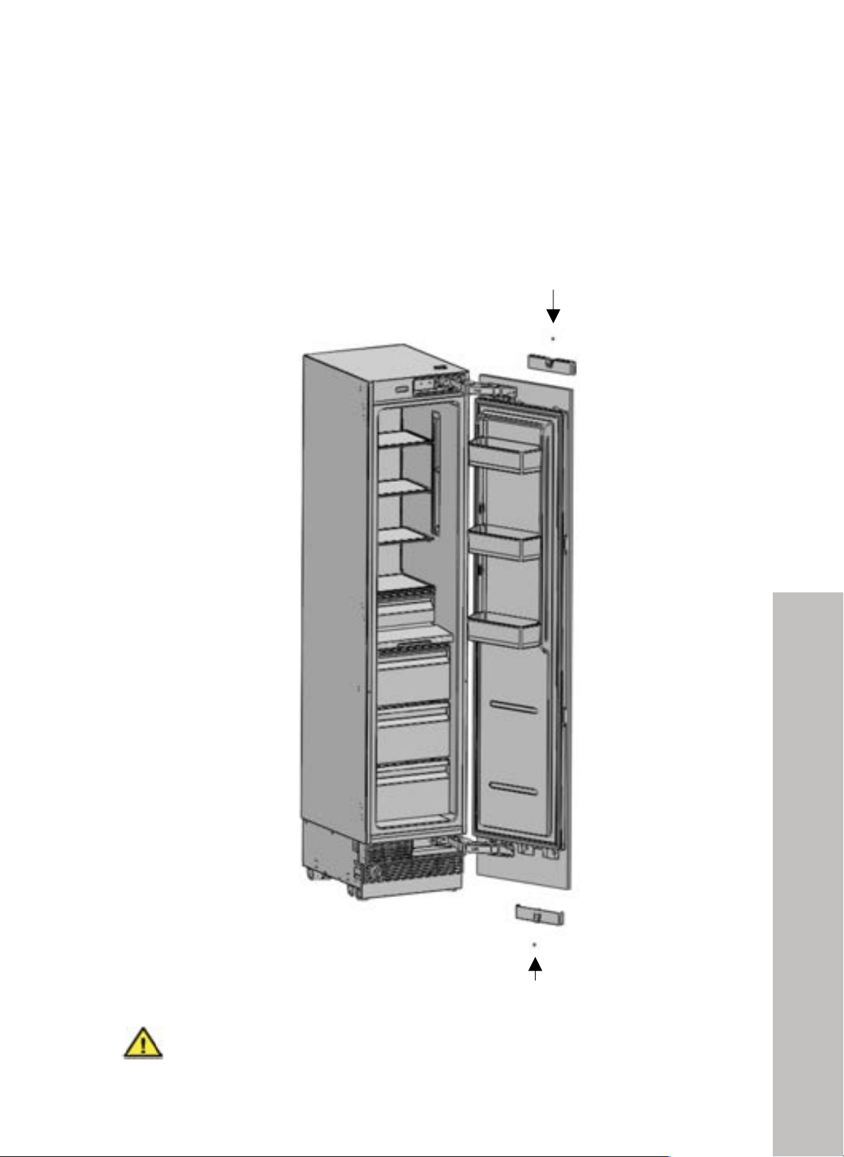
62
Door Panel Installation
INSTALLATION
SECURING THE DOOR PANEL (RBCFVL-18/RBCFVR-18)
• Re-attach and screw in the upper/lower cover mounting brackets that were
removed on page 50.
!"#$%&'#(%)*!
&*"
"
•! A>>3@7"345"2@:8L">78"M??8:g10L8:"58@0:3>904"@0Q8:<"
"
+
+
+
+
!
!
!
!
!
!
!
!
!
!
!
!
!
!
!
!
!
!
!
!
!
!
!
!
!
!
!
!
!
!
!
!
+
+
+
+
+
+
+
+
+
+
+
+
"*
$,-'()*(+!
WARNING
When finishing the installation, ensure the trim covers are secured back in their
original position and the magnet is detected properly. This is an essential part of
the unit’s functionality.
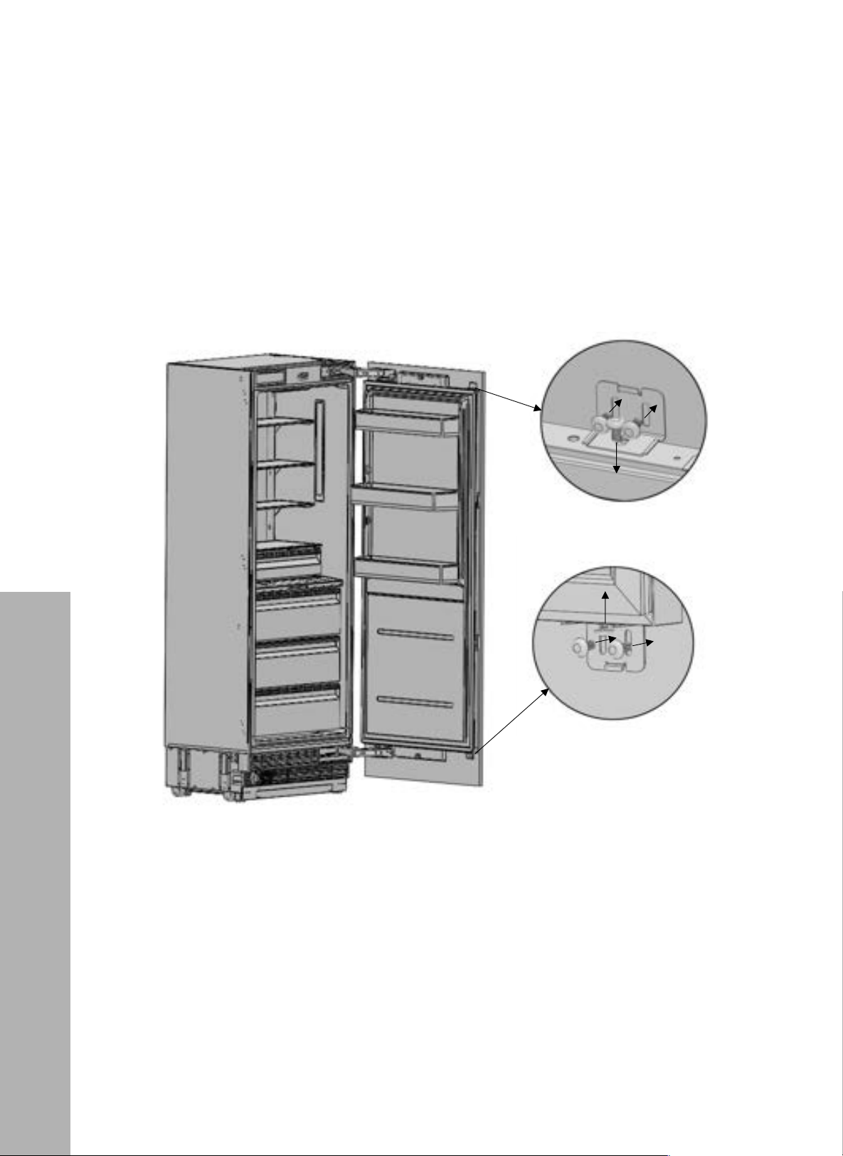
63
Door Panel Installation
INSTALLATION
SECURING THE REFRIGERATOR DOOR PANEL (RBCFV-24/RBCRV-24/RBCRV-30)
• Once the refrigerator door is aligned at top and bottom, use the door panel connecting
bracket (page 26, Item No. 6) to connect to the door.
• Use one door screw (page 26, Item No. 5) to attach each bracket onto the door.
• Use two door screws (page 26, Item No. 7) to attach each bracket onto the panel.
!"#$%&'#(%)*!
&("
"
!
!
•! O28">78"/:3@P8>"KM:49>M:8"500:`=>8."E0'a">0"V094">78"KM:49>M:8"500:"
•! O28"#2@:8L2"`=>8."E0(a"345"!2@:8L`=>8."E0&a">0"K9_<"
"
!
!
!
!
!
!
!
!
!
!
!
!
!
!
!
!
!
!
!
!
!
!
!
!
!
!
!
!
!
!
!
!
!
!
!
!
!
!
!
!
!
!
!
!
!
"*$./'()*(+!
"#$./'()*(+!
"#$%&'()*(+!
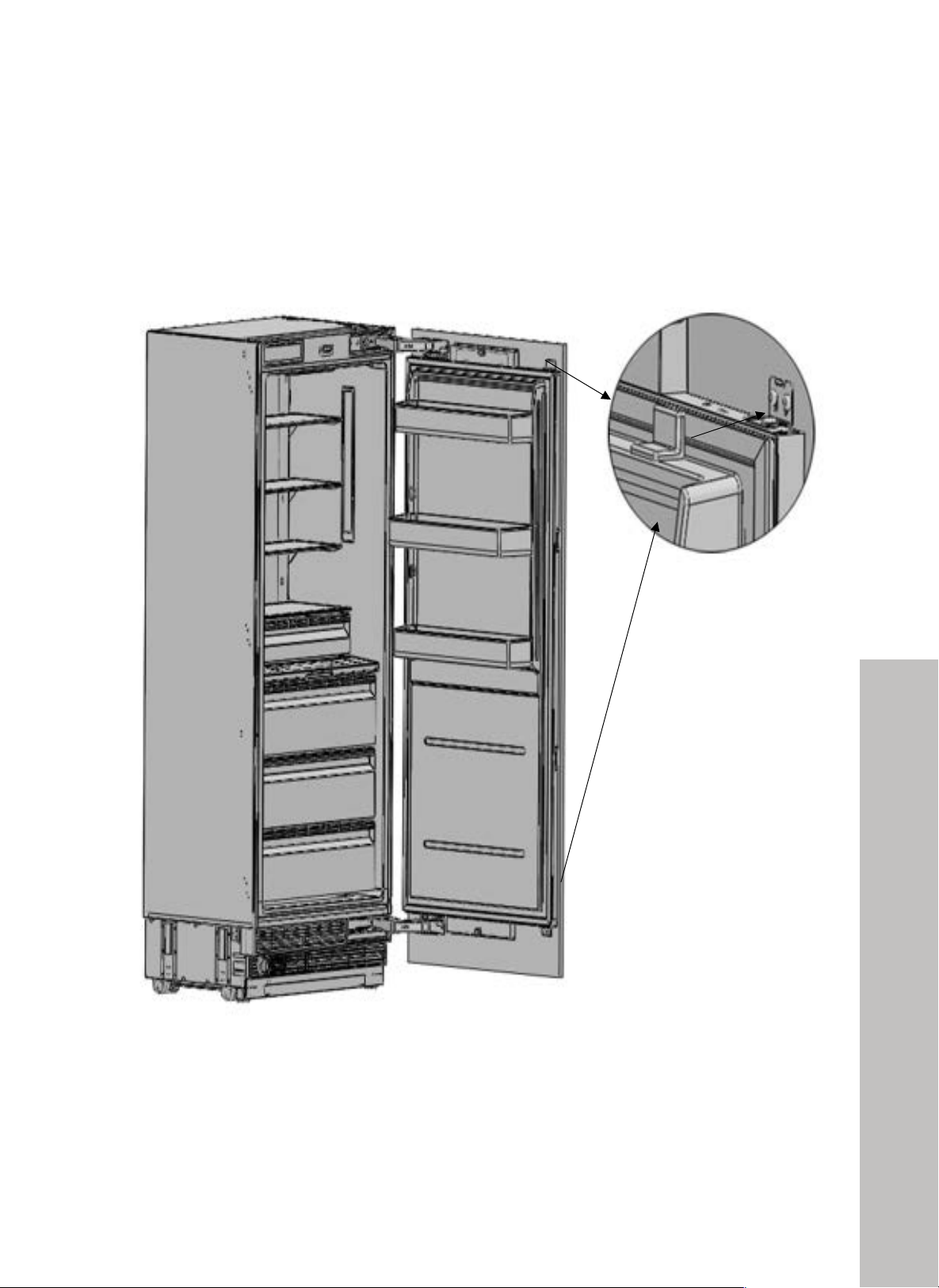
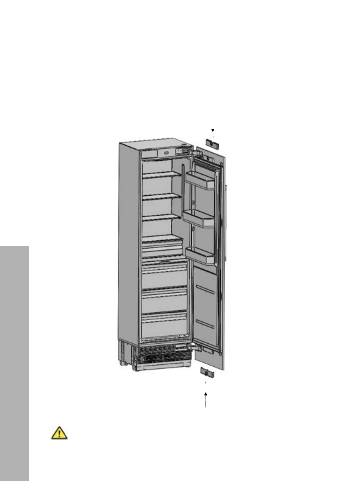
65
INSTALLATION
SECURING THE DOOR PANEL (RBCFV-24/RBCRV-24)
• Re-attach and screw in the upper/lower cover mounting brackets that were
removed on page 50.
!"#$%&'#(%)*!
'+"
"
•! A>>3@7"345"2@:8L">78"M??8:g10L8:"58@0:3>904"@0Q8:<"
+
+
+
+
+
+
+
+
+
+
+
+
+
+
+
+
+
+
+
+
+
+
+
+
+
+
+
+
+
+
+
+
+
+
+
+
+
+
+
+
+
+
+
+
+
+
+
+
+
+
+
+
+
+
+
+
+
+
+
+
+
+
6G
R#%U=EG=A"
6B
R#%U=EG=A"
WARNING
When finishing the installation, ensure the trim covers are secured back in their
original position and the magnet is detected properly. This is an essential part of
the unit’s functionality.
Door Panel Installation
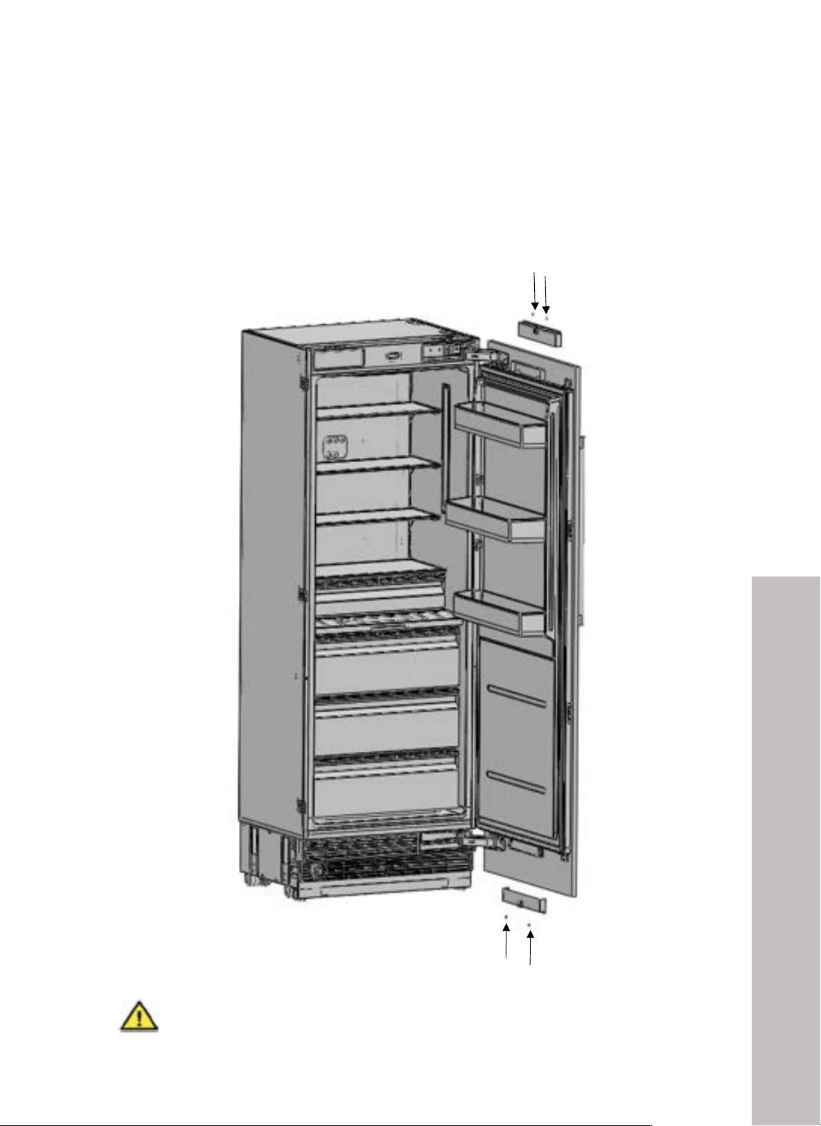
66
INSTALLATION
SECURING THE DOOR PANEL (RBCRV-30)
• Re-attach and screw in the upper/lower cover mounting brackets that were
removed on page 50.
!"#$%&'#(%)*!
'!"
"
+
+
•! A>>3@7"345"2@:8L">78"M??8:g10L8:"58@0:3>904"@0Q8:<"
+
+
+
+
+
+
+
+
+
+
+
+
+
+
+
+
+
+
+
+
+
+
+
+
+
+
+
+
+
+
+
+
+
+
+
+
+
+
+
+
+
+
+
+
+
+
+
+
+
+
+
+
+
+
! ! !"#$%$&'(
]0M".M2>"P88?">7828"?3:>2"K0:"KM>M:8"M28<"]0M"L911"4885">78."9K"-0M"L34>">0"@734;8">78"500:"59:8@>9042<"
"
"
#$%&'()*(+!
WARNING
When finishing the installation, ensure the trim covers are secured back in their
original position and the magnet is detected properly. This is an essential part of
the unit’s functionality.
Door Panel Installation
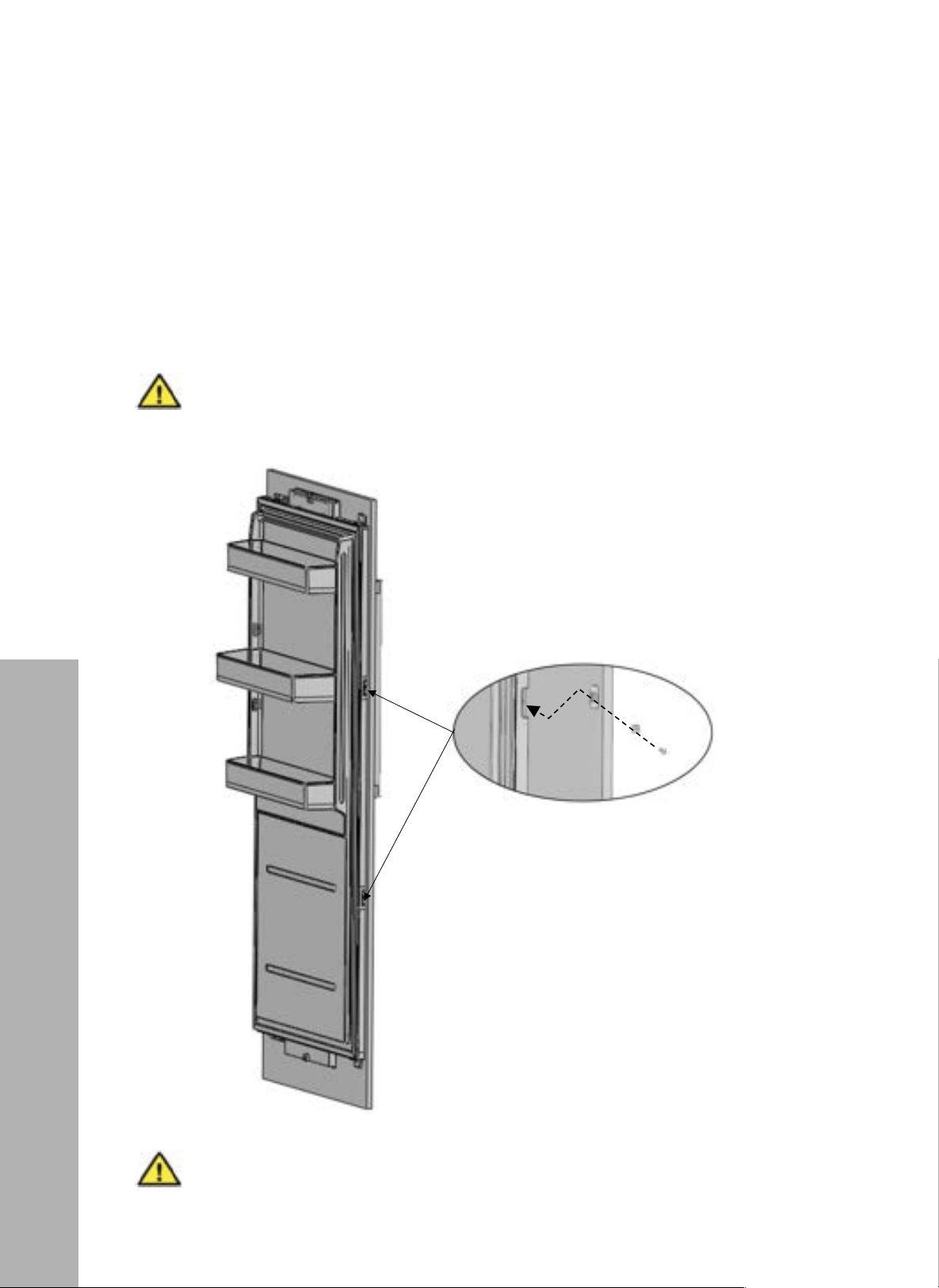
67
INSTALLATION
SECURING THE DOOR PANEL
• Re-attach and screw in the upper/lower cover mounting brackets that were
removed on page 50.
• Secure the panel side mounting bracket at the door side by using screws (Item No. 8) and
washer (Item No. 9).
WARNING
You must keep these parts for future use. You will need them if you want to change
the door directions if desired.
!"#$%&'#(%)*!
'#"
"
"
"
!!
! "#$%&!$'%!$()!*+,!-($$(.!,((&!)*+%/!-&*01%$2!*&%!2%03&%,!-4!5+2$*//5+6!20&%728"
M28"2@:8L`=>8."E0)a"345"2bM3:8"L3278:`=>8."E0*a">0"28@M:8">78"@84>8:".0M4>94;"/:3@P8><"
"
"
"
"
"
"
"
"
"
"
"
"
"
"
"
"
"
"
"
"
"
"
"
"
"
"
"
"
"
"
"
"
"
"
"
"
"
"
"
"
!
!
WARNING
When finishing the installation, ensure the trim covers are secured back in their
original position and the magnet is detected properly. This is an essential part of
the unit’s functionality.
Door Panel Installation
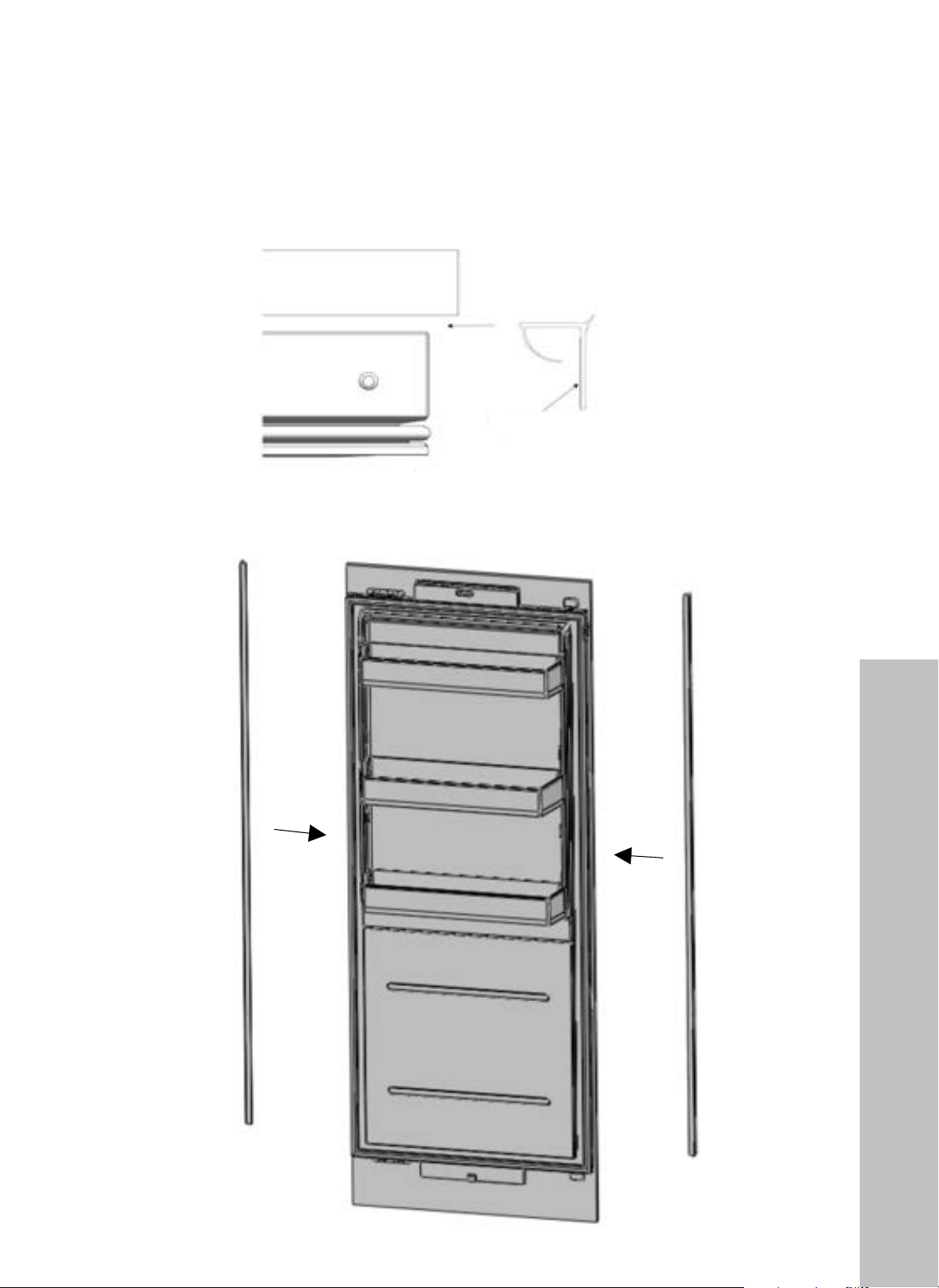
68
INSTALLATION
SECURING THE DOOR PANEL
• Attach the trim door side (Item No. 3) as outlined below.
!"#$%&'#(%)*!
'$"
"
+
•! A>>3@7">78"6:9."500:"2958"`=>8."E0$a"
+
+
+
+
+
+
+
+
+
+
+
+
+
+
+
+
+
+
+
+
+
+
+
+
+
+
+
+
+
+
+
+
Double
sided tape
Door Panel Installation
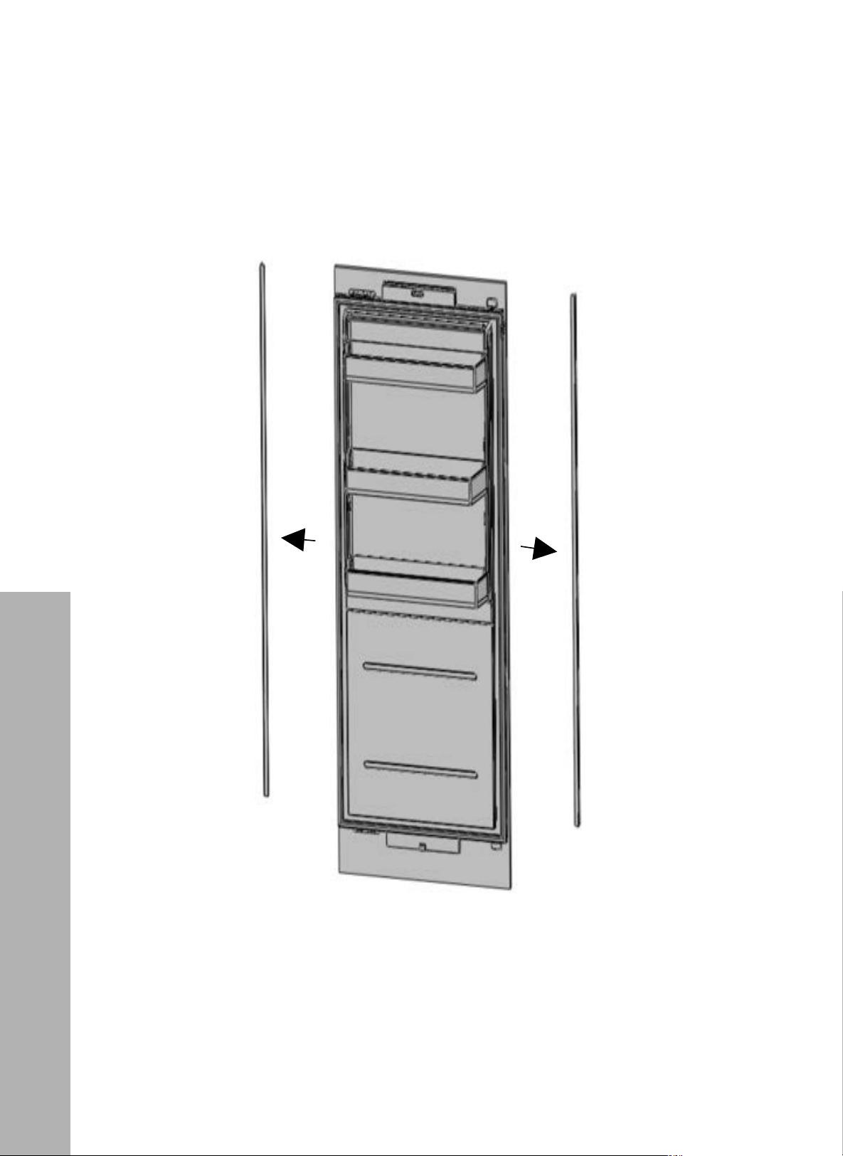
69
Changing the Direction of the Door
INSTALLATION
CHANGING THE DIRECTION OF THE REFRIGERATOR DOOR
(RBCFV-24/RBCRV-24/RBCRV-30)
• Remove the side closing seals.
!"#$%&'#(%)*!
'&"
"
!
@H7;K3;K(,H9(M>>:(>?9;3;K(M3:9@,3>;(
:.#%F/*2(4-.(AC*/4C0.(+%%0(
•! ,8>">78"73:54822"18Q81"0K">78"794;8">0"e+e<"
"
"
"
"
"
"
"
"
"
"
"
"
"
"
"
"
"
"
"
"
! "))*$)%+$'(
G391M:8">0"28>">78"794;8">0"e+e"345"@04>94M94;">78"942>3113>904"19P8">73>".3-"@3M28"94VM:-<"
"
•! D8.0Q8">78"2958"@10294;"28312<"
"
"
"
"
"
"
"
"
"
"
"
"
"
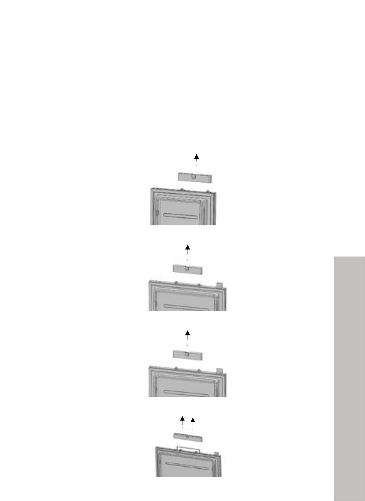
70
Changing the Direction of the Door
INSTALLATION
CHANGING THE DIRECTION OF THE REFRIGERATOR DOOR
(RBCFV-24/RBCRV-24/RBCRV-30)
REMOVING THE DOOR BRACKET COVERS
• Loosen screws of the upper cover of the door and remove it.
RBCFVL-18/RBCFVR-18
!"#$%&'#(%)*!
''"
"
!
•! B00284"2@:8L2"0K">78"O??8:"J0Q8:"0K">78"500:"345":8.0Q8"9><"
!
!
!
!
!
!
!
!
!
!
!
!
!
!
!
!
!
!
!
!
!
!
!
!
!
"
"
"
"
"
"
"
"
"
"
"
"
"
"#$%&'()*(+!
"*
$,-'()*(+!
6GR#%U=EG=A"
6BR#%U=EG=A"
"
RBCFV-24
!"#$%&'#(%)*!
''"
"
!
•! B00284"2@:8L2"0K">78"O??8:"J0Q8:"0K">78"500:"345":8.0Q8"9><"
!
!
!
!
!
!
!
!
!
!
!
!
!
!
!
!
!
!
!
!
!
!
!
!
!
"
"
"
"
"
"
"
"
"
"
"
"
"
"#$%&'()*(+!
"*
$,-'()*(+!
6GR#%U=EG=A"
6BR#%U=EG=A"
"
RBCRV-24
!"#$%&'#(%)*!
''"
"
!
•! B00284"2@:8L2"0K">78"O??8:"J0Q8:"0K">78"500:"345":8.0Q8"9><"
!
!
!
!
!
!
!
!
!
!
!
!
!
!
!
!
!
!
!
!
!
!
!
!
!
"
"
"
"
"
"
"
"
"
"
"
"
"
"#$%&'()*(+!
"*
$,-'()*(+!
6GR#%U=EG=A"
6BR#%U=EG=A"
"
RBCRV-30
!"#$%&'#(%)*!
''"
"
!
•! B00284"2@:8L2"0K">78"O??8:"J0Q8:"0K">78"500:"345":8.0Q8"9><"
!
!
!
!
!
!
!
!
!
!
!
!
!
!
!
!
!
!
!
!
!
!
!
!
!
"
"
"
"
"
"
"
"
"
"
"
"
"
"#$%&'()*(+!
"*
$,-'()*(+!
6GR#%U=EG=A"
6BR#%U=EG=A"
"
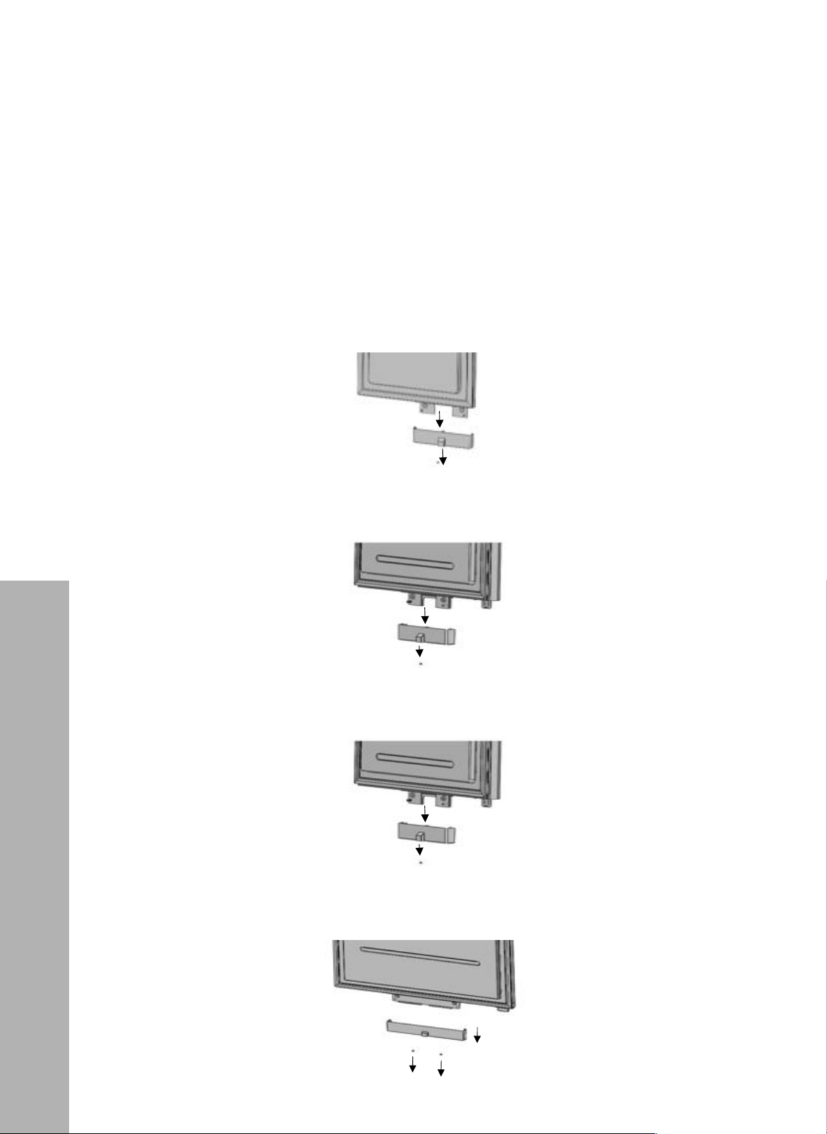
71
Changing the Direction of the Door
INSTALLATION
CHANGING THE DIRECTION OF THE REFRIGERATOR DOOR
(RBCFV-24/RBCRV-24/RBCRV-30)
REMOVING THE DOOR BRACKET COVERS
• Loosen screws of the lower cover of the door and remove it.
RBCFVL-18/RBCFVR-18
!"#$%&'#(%)*! !
%("
"
•! D8.0Q8"2@:8L">0">3P8"0M>">78"10L"734;8:"/:3@P8>"@0Q8:<"
!
(
(
(
(
(
(
(
(
(
"
"
"
"
"
"
"
"
"
"
"
"
"
"
"
"
"
"
"
"
"
"
"
"*
$,-'()*(+!
6GR#%U=EG=A"
6
BR#%U=EG=A"
"
6
BR$+U=EG=A"
RBCFV-24
!"#$%&'#(%)*! !
%("
"
•! D8.0Q8"2@:8L">0">3P8"0M>">78"10L"734;8:"/:3@P8>"@0Q8:<"
!
(
(
(
(
(
(
(
(
(
"
"
"
"
"
"
"
"
"
"
"
"
"
"
"
"
"
"
"
"
"
"
"
"*
$,-'()*(+!
6GR#%U=EG=A"
6
BR#%U=EG=A"
"
6
BR$+U=EG=A"
RBCRV-24
!"#$%&'#(%)*! !
%("
"
•! D8.0Q8"2@:8L">0">3P8"0M>">78"10L"734;8:"/:3@P8>"@0Q8:<"
!
(
(
(
(
(
(
(
(
(
"
"
"
"
"
"
"
"
"
"
"
"
"
"
"
"
"
"
"
"
"
"
"
"*
$,-'()*(+!
6GR#%U=EG=A"
6
BR#%U=EG=A"
"
6
BR$+U=EG=A"
RBCRV-30
!"#$%&'#(%)*! !
%("
"
•! D8.0Q8"2@:8L">0">3P8"0M>">78"10L"734;8:"/:3@P8>"@0Q8:<"
!
(
(
(
(
(
(
(
(
(
"
"
"
"
"
"
"
"
"
"
"
"
"
"
"
"
"
"
"
"
"
"
"
"*
$,-'()*(+!
6GR#%U=EG=A"
6
BR#%U=EG=A"
"
6
BR$+U=EG=A"
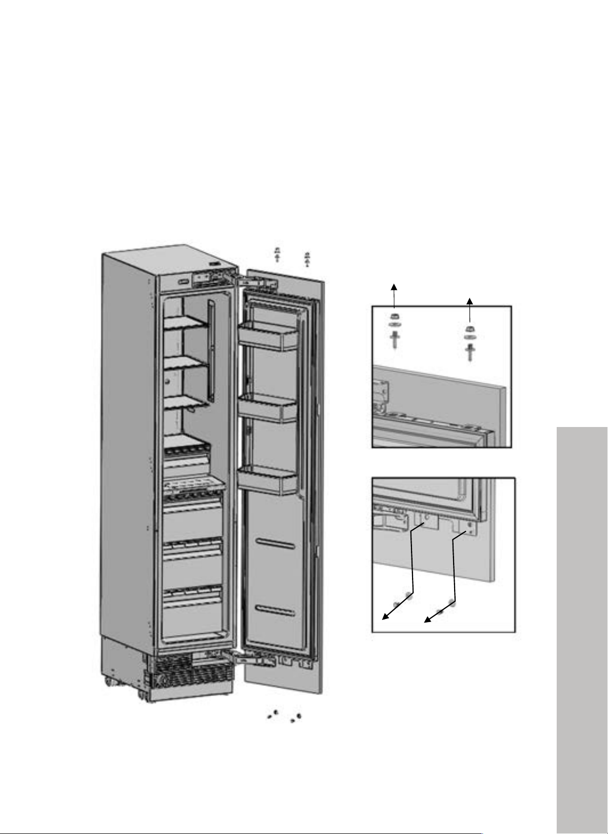
72
Changing the Direction of the Door
INSTALLATION
CHANGING THE DIRECTION OF THE REFRIGERATOR DOOR
(RBCFV-24/RBCRV-24/RBCRV-30)
REMOVING THE DOOR BRACKET COVERS
• Remove the upper and lower adjustment kits.
!"#$%&'#(%)*!
')"
"
!
•! D8.0Q8">78"M??8:"35VM2>.84>"P9>2<"
"
"
"
"
"
"
"
"
"
"
"
"
"
"
"
"
"
"
"
"
"
"
"
"
"
"
"
"
"
"
"
"
"
"
"
"
"
"
"
"
"*
$,-'()*(+!
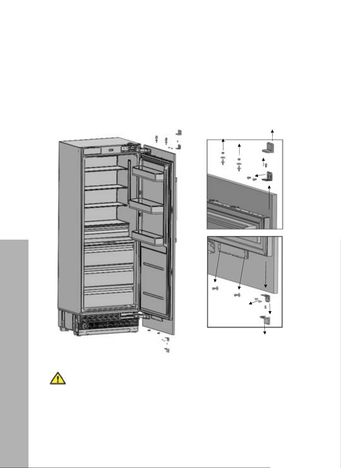
73
Changing the Direction of the Door
INSTALLATION
CHANGING THE DIRECTION OF THE REFRIGERATOR DOOR
(RBCFV-24/RBCRV-24/RBCRV-30)
REMOVING THE DOOR BRACKET COVERS
• Remove the upper and lower adjustment kits.
!"#$%&'#(%)*!
'*"
"
"
"
!
!
!
!
!
!
!
!
!
!
!
!
!
!
!
!
!
!
!
!
!
!
!
!
+
"
"
! !"#$%$&'(
678"@135"500:"L911"/8":8183285"L784">7828"2@:8L2"3:8":8.0Q85<" "
]0M".M2>">3P8".832M:82">0"?:8Q84>">78"500:"K:0."K31194;<"
!
]0M"@34">3?8">78"GM:49>M:8"Y00:">0">78"=448:"Y00:"0:"32P"K0:"781?"K:0."340>78:"?8:204<"
!
!
•! 63P8">78"G:95;8"GM:49>M:8"Y00:"345"13-"9>"50L4"04"3">3/18"M?2958"50L4<" "
•! ]0M".M2>"3>>3@7">78"GM:49>M:8"Y00:"/-":0>3>94;"9>"!)+f"/3285"04"9>2"@M::84>"?029>904<"
6G
R#%U=EG=A"
6B
R#%U=EG=A"
"
#$%&'()*(+!
WARNING
The refrigerator door assembly will be free once these screws are removed. It will
be heavy; be sure to take measures to prevent the door from falling or causing
any damage or injury.
• You can tape the door panel to the inner door or ask for help from another person.
• Once the panel is removed, lay it down on a table upside down.
• You must attach the door panel by rotating it 180° based on its current position.
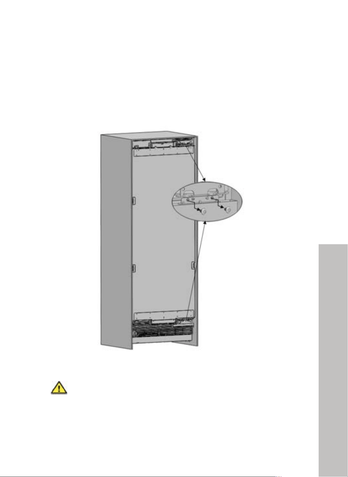
74
INSTALLATION
CHANGING THE DIRECTION OF THE REFRIGERATOR DOOR
(RBCFV-24/RBCRV-24/RBCRV-30)
REMOVING AND PREPARING THE INNER DOOR
• Remove the 4 hinge connection screws of the hinge brackets as shown below.
!"#$%&'#(%)*!
(+"
"
!
:.#%F/*2()*+(50.5)0/*2(4-.(/**.0(+%%0(
•! D8.0Q8">78"794;8"@0448@>904"2@:8L2"0K">78"T94;8"U:3@P8>2<"
!
!
!
!
!
"
!
!
!
!
!
!
!
!
!
!
!
!
!
!
!
!
!
!
!
!
!
!
!
!
"))*$)%+$'! (
678"@135"500:"L911"/8":8183285"L784">7828"2@:8L2"3:8":8.0Q85<" "
]0M".M2>">3P8".832M:82">0"?:8Q84>">78"500:"K:0."K31194;<"
]0M"@34">3?8">78"GM:49>M:8"Y00:">0">78"=448:"Y00:"0:"32P"K0:"781?"K:0."340>78:"?8:204<"
+
!
WARNING
The refrigerator door assembly will be free once these screws are removed. It will
be heavy; be sure to take measures to prevent the door from falling or causing
any damage or injury.
• You can tape the door panel to the inner door or ask for help from another person.
• Once the panel is removed, lay it down on a table upside down.
• You must attach the door panel by rotating it 180° based on its current position.
Changing the Direction of the Door
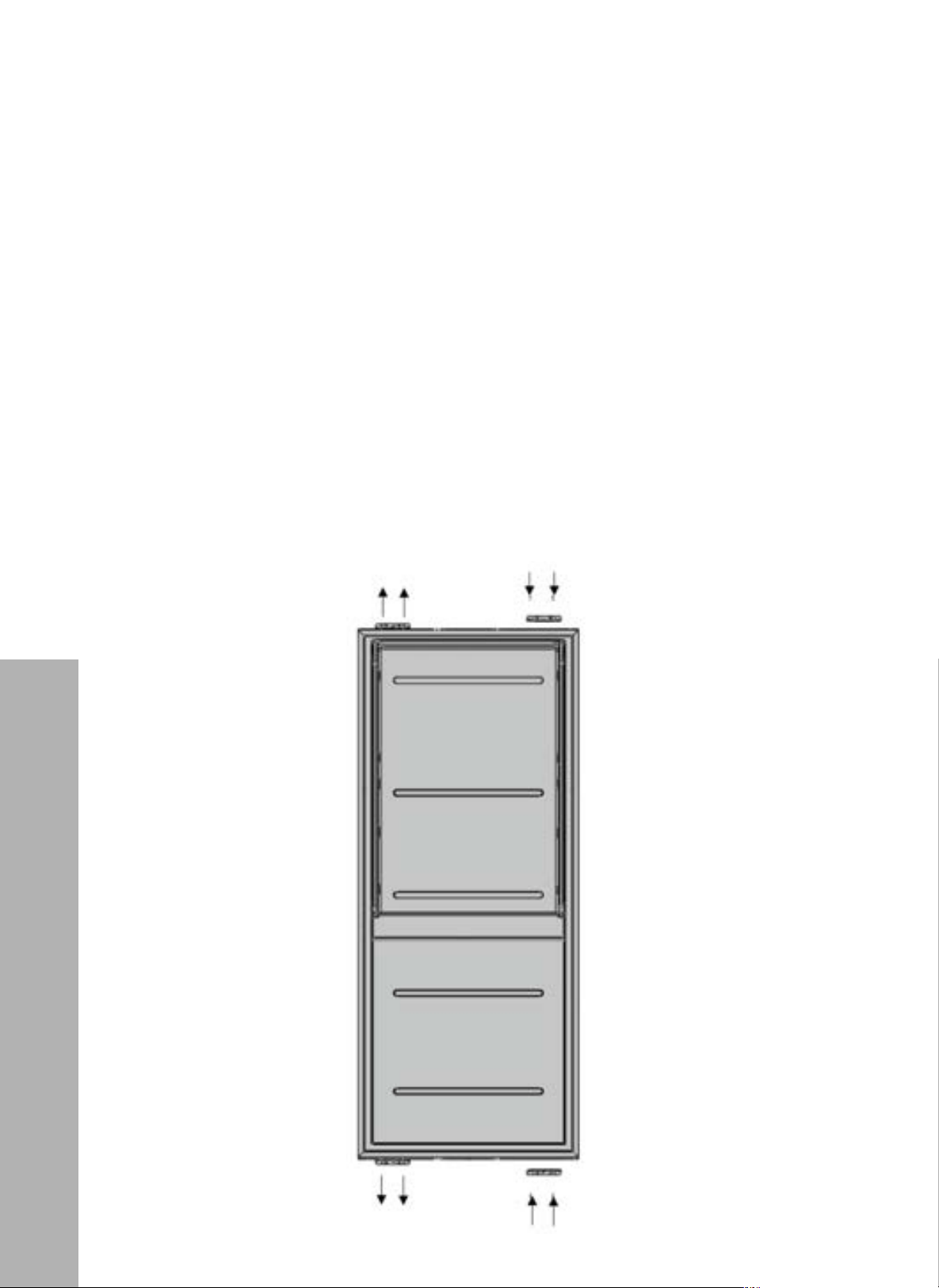
75
INSTALLATION
CHANGING THE DIRECTION OF THE REFRIGERATOR DOOR
(RBCFV-24/RBCRV-24/RBCRV-30)
NOTE: It's important to note that the two metal connection brackets (Item Nos. 20 and 21) are
not identical. When reversing the hinge, the connection brackets must be re-installed. The hinge
brackets are marked with the letters ''L'' or ''R'' letter to help distinguish the position. The top uses
the smaller bracket and the bottom uses the bigger bracket. For example, If the hinge position is
on the left side, please make sure the connector brackets you are using are marked with letter
''L''. The smaller bracket must be on top. Otherwise, the door will have gaps.
1. Take out the door and lay it down on a table.
2. Remove the brackets on the fridge door.
3. Using the new hinge brackets from the parts bag, screw the brackets onto the reverse sides.
Changing the Direction of the Door
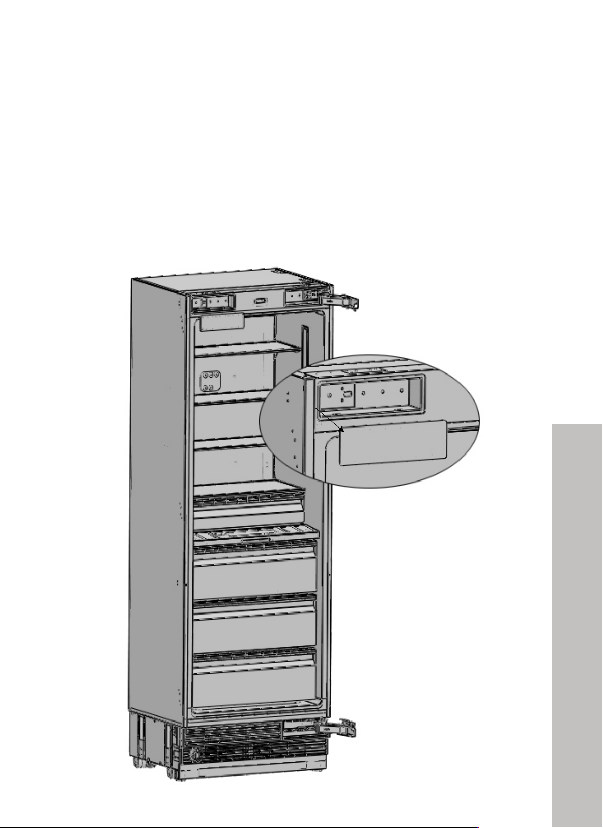
76
CHANGING THE DIRECTION OF THE REFRIGERATOR DOOR
(RBCFV-24/RBCRV-24/RBCRV-30)
REPLACING THE HINGES
• Remove the hinge caps located at the other side where you will fix the hinges as
outlined below.
!"#$%&'#(%)*!
(#"
"
:.5&)6/*2(4-.(-/*2.'(
"
•! D8.0Q8">78"T94;8"J3?2"10@3>85"3>">78"0>78:"2958"L78:8"-0M"L911"K9_">78"794;82<"
+
"
!
INSTALLATION
Changing the Direction of the Door
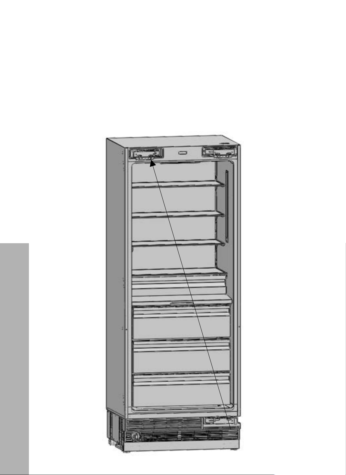
77
INSTALLATION
CHANGING THE DIRECTION OF THE REFRIGERATOR DOOR
(RBCFV-24/RBCRV-24/RBCRV-30)
REPLACING THE HINGES
• Remove the lower right hinge by loosening its two screws and fix it to its slot at the upper
left side as outlined below.
!"#$%&'#(%)*! !
($"
"
•! D8.0Q8">78"10L8:":9;7>"794;8"/-"10028494;"9>2"#"2@:8L2"345"K9_"9>">0"9>2"210>"3>">78"M??8:"18K>"2958<"
!
+
+
+
+
+
+
+
+
+
!
"
"
"
"
"
"
"
"
"
"
"
"
"
"
"
"
"
"
"
"
"
"
"
"
"
"
"
"
"
"
"
"
"
Changing the Direction of the Door
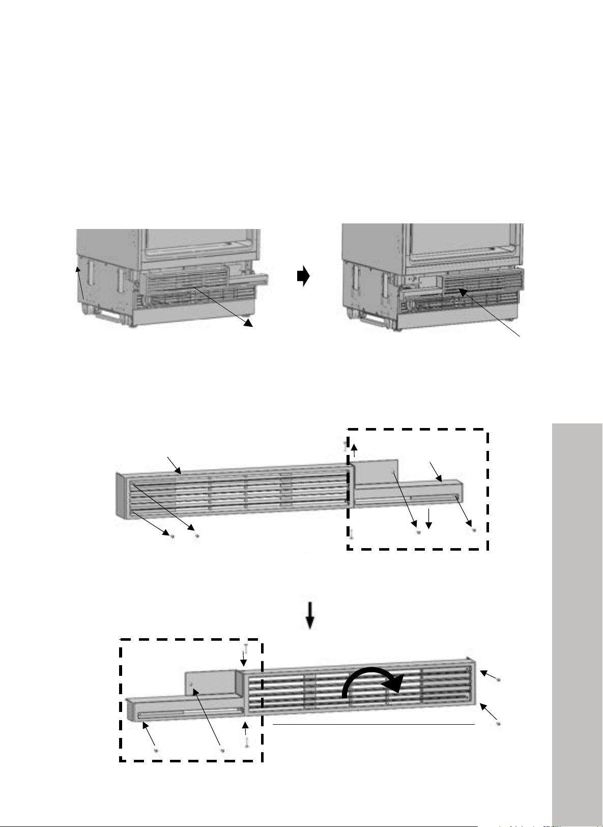
78
INSTALLATION
CHANGING THE DIRECTION OF THE REFRIGERATOR DOOR
(RBCFV-24/RBCRV-24/RBCRV-30)
AIR VENT UPPER PART DIRECTION CHANGE
Remove the air vent part and change direction as shown below.
!"#$%&'#(%)*! !
(%"
"
7/0(F.*4(C55.0(5)04(+/0.64/%*(6-)*2.(
" " D8.0Q8">78"39:"Q84>"?3:>"345",%-128"59:8@>904"32"270L4"K9;M:8"
"
"
"
"
"
"
"
"
"
!
!
!
!
!
!
!
!
!
!
!
!
!
!
!
!
!
!
!
!
!
!
!
!
!
!
!
!
!
!
!
!
!
!
!
!
!
!
!
!
!
!
!
!
!
!
!
!
!
!
!
!
!
!
!
!
!
!
!
!
!
!
!
!
!
!
!
!
!
!
!
!
!
!
!
!"#$%&'($)*%&#!
!"#$%&'($+"',&$-.#($#",+(!
/*(.(&$."#$%&'($)*%&#$01$2345$
#*(.(&!
)34(5#1$(%312#(6-4$(7#8$"
6! !"#$%&'($7--&#$-.#($8*#$(+&$#",+($+"',&!
9*:$(*$)+.',&$."#$%&'($7--&#$-.#($;"#&)("*'!
6! !"#$%&'($7--&#$-.#($8*#$(+&$<&8($+"',&
!
Air vent hinge part right
Air vent hinge part left
Air vent cover
Rotate air vent cover by 180°
How to change air vent upper part direction
• The below figure shows the vent upper part for the right hinge:
!"#$%&'#(%)*! !
(%"
"
7/0(F.*4(C55.0(5)04(+/0.64/%*(6-)*2.(
" " D8.0Q8">78"39:"Q84>"?3:>"345",%-128"59:8@>904"32"270L4"K9;M:8"
"
"
"
"
"
"
"
"
"
!
!
!
!
!
!
!
!
!
!
!
!
!
!
!
!
!
!
!
!
!
!
!
!
!
!
!
!
!
!
!
!
!
!
!
!
!
!
!
!
!
!
!
!
!
!
!
!
!
!
!
!
!
!
!
!
!
!
!
!
!
!
!
!
!
!
!
!
!
!
!
!
!
!
!
!"#$%&'($)*%&#!
!"#$%&'($+"',&$-.#($#",+(!
/*(.(&$."#$%&'($)*%&#$01$2345$
#*(.(&!
)34(5#1$(%312#(6-4$(7#8$"
6! !"#$%&'($7--&#$-.#($8*#$(+&$#",+($+"',&!
9*:$(*$)+.',&$."#$%&'($7--&#$-.#($;"#&)("*'!
6! !"#$%&'($7--&#$-.#($8*#$(+&$<&8($+"',&
!
Air vent hinge part right
Air vent hinge part left
Air vent cover
Rotate air vent cover by 180°
• Use the vent upper part (page 27, Item No. 16) for the left hinge as outlined below.
!"#$%&'#(%)*! !
(%"
"
7/0(F.*4(C55.0(5)04(+/0.64/%*(6-)*2.(
" " D8.0Q8">78"39:"Q84>"?3:>"345",%-128"59:8@>904"32"270L4"K9;M:8"
"
"
"
"
"
"
"
"
"
!
!
!
!
!
!
!
!
!
!
!
!
!
!
!
!
!
!
!
!
!
!
!
!
!
!
!
!
!
!
!
!
!
!
!
!
!
!
!
!
!
!
!
!
!
!
!
!
!
!
!
!
!
!
!
!
!
!
!
!
!
!
!
!
!
!
!
!
!
!
!
!
!
!
!
!"#$%&'($)*%&#!
!"#$%&'($+"',&$-.#($#",+(!
/*(.(&$."#$%&'($)*%&#$01$2345$
#*(.(&!
)34(5#1$(%312#(6-4$(7#8$"
6! !"#$%&'($7--&#$-.#($8*#$(+&$#",+($+"',&!
9*:$(*$)+.',&$."#$%&'($7--&#$-.#($;"#&)("*'!
6! !"#$%&'($7--&#$-.#($8*#$(+&$<&8($+"',&
!
Air vent hinge part right
Air vent hinge part left
Air vent cover
Rotate air vent cover by 180°
Changing the Direction of the Door
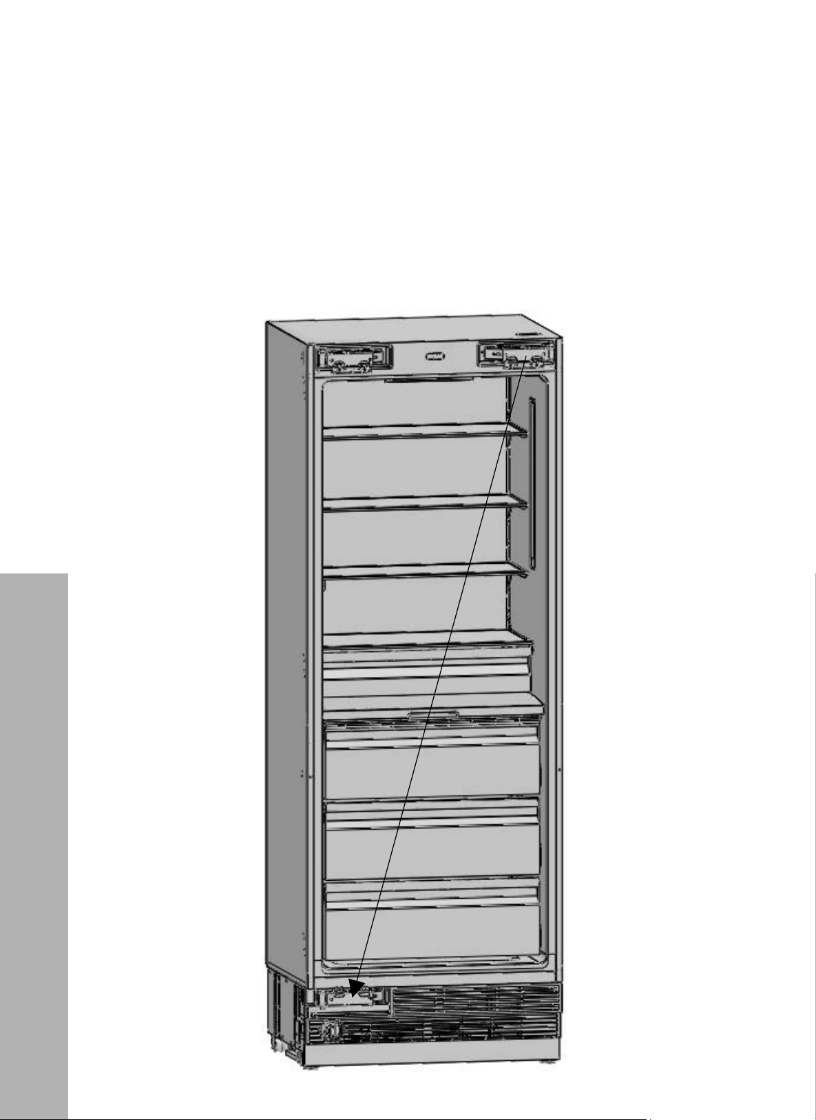
79
INSTALLATION
CHANGING THE DIRECTION OF THE REFRIGERATOR DOOR
(RBCFV-24/RBCRV-24/RBCRV-30)
REPLACING THE HINGES
• Remove the upper right hinge by loosening its two screws and fix it to its slot at the lower
left side as outlined below.
!"#$%&'#(%)*! !
(&"
"
!
!
!
!
•! "#$%&#!'(#!)??8:":9;7>"794;8"/-"10028494;"9>2"#"2@:8L2"345"K9_"9>">0"9>2"210>"3>">78"10L8:"18K>"29589""""""""""""""""
"
+
!
!
+
+
+
Changing the Direction of the Door
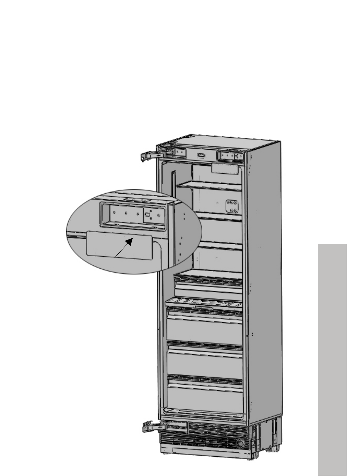
80
INSTALLATION
CHANGING THE DIRECTION OF THE REFRIGERATOR DOOR
(RBCFV-24/RBCRV-24/RBCRV-30)
REPLACING THE HINGES
• Attach the hinge slot caps removed from the left side to the hinge caps at the right side as
outlined below.
!"#$%&'#(%)*! !
('"
"
•! A>>3@7">78"T94;8",10>"J3?2":8.0Q85"K:0.">78"18K>"2958">0">78"T94;8"J3?2" "
>0">78":9;7>"2958<"
+
+
+
+
+
+
+
+
+
+
+
+
+
+
+
+
+
+
+
+
+
+
+
+
+
+
+
+
+
+
+
+
+
+
+
+
+
+
+
+
+
+
+
+
+
+
+
+
+
+
+
+
+
+
+
+
+
+
+
+
Changing the Direction of the Door
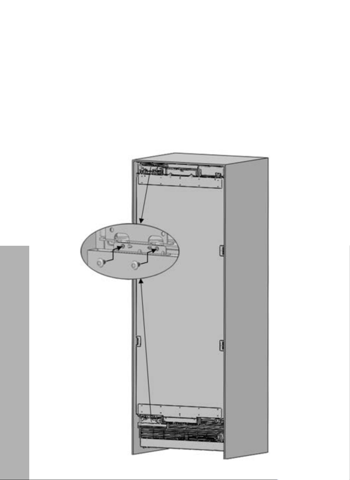
81
CHANGING THE DIRECTION OF THE REFRIGERATOR DOOR
(RBCFV-24/RBCRV-24/RBCRV-30)
RE-INSTALLING THE DOOR
• Place the refrigerator or freezer inner door to the unit and affix it with 4 screws removed on
page 74 to achieve the new door swing layout as outlined below.
!"#$%&'#(%)*! !
(("
"
3*'4)&&/*2(4-.(+%%0!
!! I13@8">78"500:">0">78":8K:9;8:3>0:"345"K9_"9>"L9>7"%"2@:8L2<! ! !
!
!
!
!
+
+
+
+
+
+
+
+
+
+
+
+
+
+
+
+
+
+
+
+
+
+
+
+
+
+
+
+
+
+
+
+
+
+
+
+
+
+
+
+
+
+
+
+
+
+
+
+
+
+
+
+
+
INSTALLATION
Changing the Direction of the Door
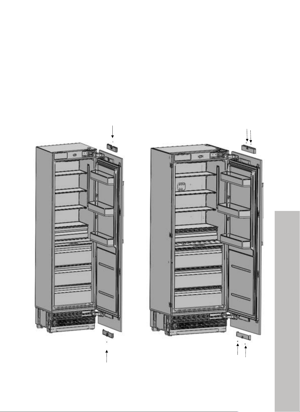
82
Changing the Direction of the Door
INSTALLATION
CHANGING THE DIRECTION OF THE REFRIGERATOR DOOR
(RBCFV-24/RBCRV-24/RBCRV-30)
SECURING THE DOOR PANEL
• Attach and screw the upper/lower decoration cover.
RBCFV-24/RBCRV-24
RBCRV-30
!"#$%&'#(%)*!
'+"
"
•! A>>3@7"345"2@:8L">78"M??8:g10L8:"58@0:3>904"@0Q8:<"
+
+
+
+
+
+
+
+
+
+
+
+
+
+
+
+
+
+
+
+
+
+
+
+
+
+
+
+
+
+
+
+
+
+
+
+
+
+
+
+
+
+
+
+
+
+
+
+
+
+
+
+
+
+
+
+
+
+
+
+
+
+
6G
R#%U=EG=A"
6B
R#%U=EG=A"
!"#$%&'#(%)*!
'!"
"
+
+
•! A>>3@7"345"2@:8L">78"M??8:g10L8:"58@0:3>904"@0Q8:<"
+
+
+
+
+
+
+
+
+
+
+
+
+
+
+
+
+
+
+
+
+
+
+
+
+
+
+
+
+
+
+
+
+
+
+
+
+
+
+
+
+
+
+
+
+
+
+
+
+
+
+
+
+
+
! ! !"#$%$&'(
]0M".M2>"P88?">7828"?3:>2"K0:"KM>M:8"M28<"]0M"L911"4885">78."9K"-0M"L34>">0"@734;8">78"500:"59:8@>9042<"
"
"
#$%&'()*(+!
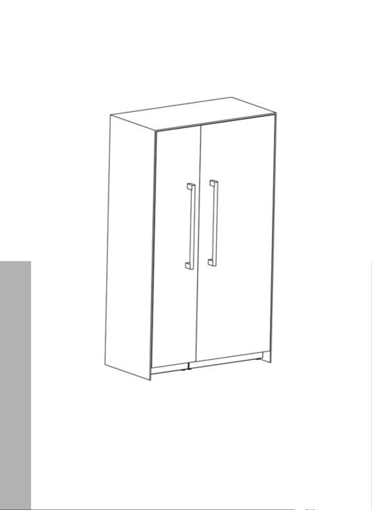
83
DUAL CABIN INSTALLATION
DUAL CABIN INSTALLATION
*
! 7*, - $.)&*'%&'()#$$#)&*'
A >(98%3'37?"#'&%%&'?("75("H3)7'(78)3@?($#78&E3#7)3E&)D?"E7('C3)7?"#'&%%&'?("78)(53D$)3#,
!"#$%&'#(%)*! !
*!"
"
]0M"@34"288"?:8Q90M2"?3;82"K0:"0>78:"942>3113>904"?:0@85M:82<+
+
+
+
+
+
+
+
+
+
+
+
+
+
+
+
+
+
+
+
+
+
+
+
+
+
+
+
+
+
+
+
+
+
+
+
+
+
+
+
+
+
+
+
+
+
+
+
+
+
Dual Cabin Installation
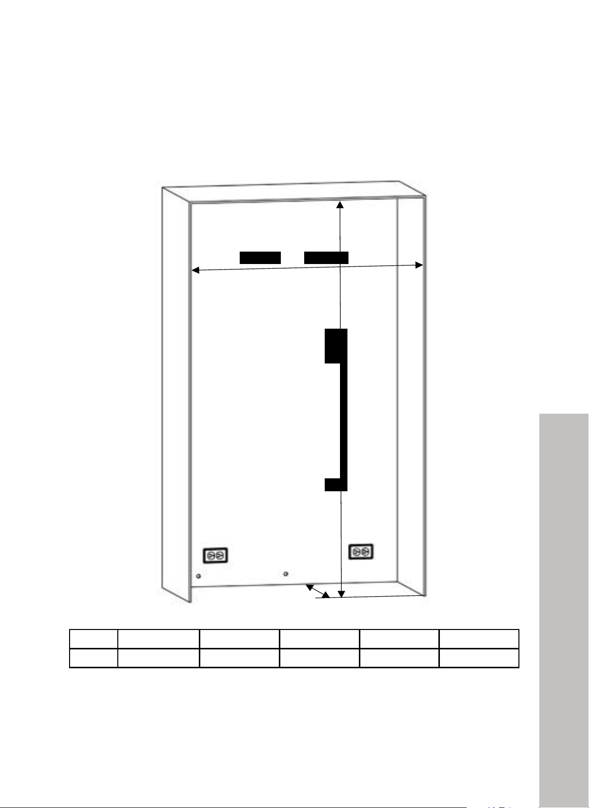
84
DUAL CABIN INSTALLATION
CABINET DIMENSIONS
• Since all kitchen layouts vary, the recommended dimensions below must be checked by a
qualified professional before starting installation.
!"#$%&'#(%)*! !
()"
"
3*'4)&&/*2(4-.(+C)&(6)$/*(
=K"-0M"3:8";094;">0".3P8"3"5M31"@3/94"942>3113>904\"-0M".M2>"58K949>81-"58.345"eYM31"J3/94"=42>3113>904"c9>e" "
K:0.">78"3M>70:9285"28:Q9@8<" "
678"942>:M@>9042"/810L"73Q8"/884"?:8?3:85"3@@0:594;">0"UM91>R94">-?8<" "
UM91>R94["678"A??1934@8"345"I34812"KM11-"283>"94>0">78";3?\"345"3".3>8:931">73>"@34"/8">789:"0L4"/0_"92"V3..85"
/8>L884">78">L0"P9>@784"@3/948>2"0:"58@0:3>9Q8"@01M.42<"6792"92">78".02>"@0..04"942>3113>904"2@843:90<" "
"
"#$%&!'%()&*%+&*! !
J3/94"59.8429042"/810L".M2>"/8"@78@P85"/8K0:8"2>3:>94;">78"942>3113>904<" "
+
+
+
+
+
+
+
+
+
+
+
+
+
+
+
+
+
+
+
+
+
+
+
+
+
+
+
+
+
+
+
+
+
+
+
+
+
"!
!"#$%&#'()%*(+,)-(.))
)
+
"!
!&LR$'$LQ$)
+
+
+
+
+
+
./012345+ !"D&#+ !"D,(+ &#D&#+ &#D,(+ ,(D,(+
E*F+=@>1AG@3A+ #&F+H!(''>>I+ #"F+H!&!)>>I+ #"F+H!&!)>>I+ $#F+H!,%!>>I+ '(F+H!$&#>>I+
./012345+ 678!"9:;7:*+ 678	:;7:*+ 678	:;7:*+ 6<8,(9:;7:*+
*JJ41K@/0@3A+ !"+ &#+ &#+ ,(+
I#.
!
3T.) /-G6T445
!
-0)
!
25" (635 mm)
A
84" (2137 mm)
Category 18" + 24" 18" + 30" 24" + 24" 24" + 30" 30" + 30"
A 42 1/8" (1070 mm) 48 1/8" (1222 mm) 48 1/8" (1222 mm) 54 1/8" (1375 mm) 60 1/8" (1527 mm)
Cabinet Cutout Dimensions
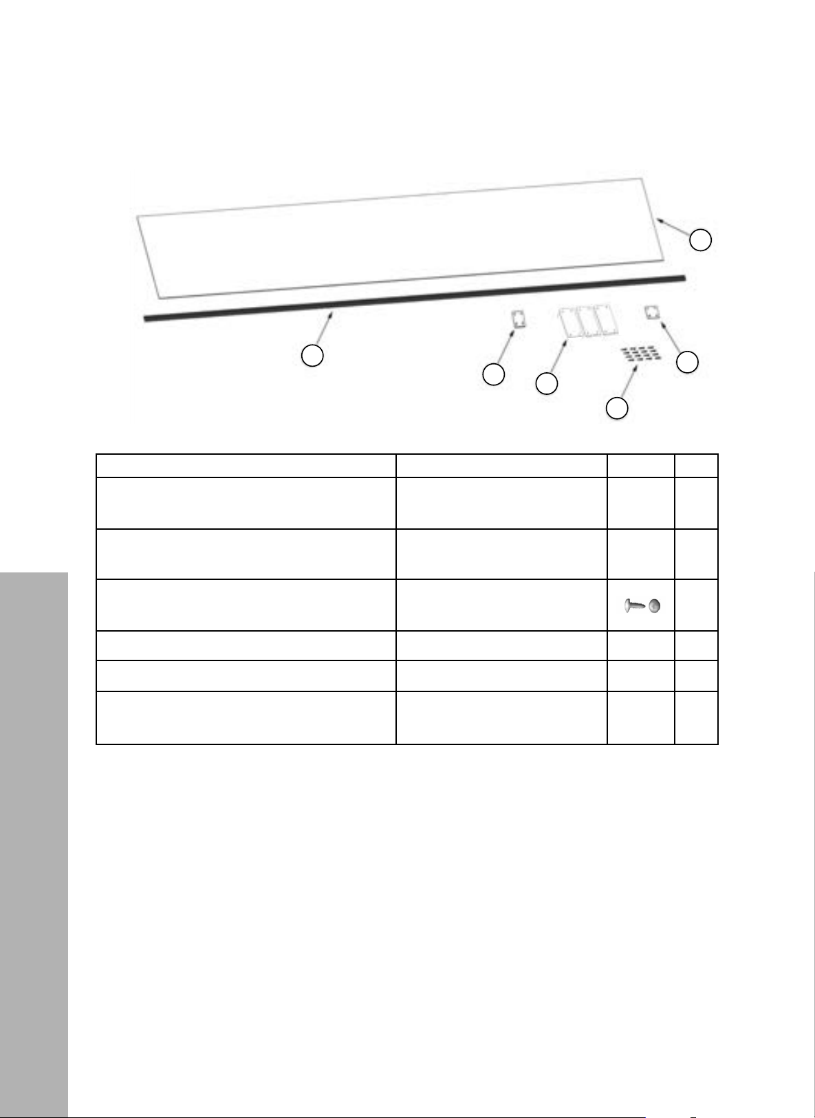
85
DUAL CABIN INSTALLATION
JOINING KIT PARTS PROVIDED
!"#$%&'#(%)*! !
)!"
"
+
+
+
+
+
+
+
+
+
+
+
+
+
+
+
+
+
+
+
+
+
+
+
+
+
+
+
+
+
+
+
+
+
+
+
+
+
+
+
+
+
+
+
+
+
+
+
+
+
+
+
+
+
+
+
+
+
+
+
+
+
+
1&) ]"'#)L"F$) ^K$Q) jk#() P$F"'?)
-) 0L=J:"#H&L)=K&L%$) ^K&L%$a)%'"(a)*6V7d477d-BA7) -) )
3) !&LL$Q#HL%)<'"Q?$#)>2Z) *3V7dAEd4-a) ) !'bcL,Q&"#HL%) -) )
6) *'J==)G"=I$')I$";) 84d-3) -E) )
4) +"=#$L$') ]l8) 6) )
A) *'HF)RJ'LH#J'$)FH;;:$) ]_!)$9#'J=H&L)5`-.BE) -) )
E) !&LL$Q#HL%)<'"Q?$#)>/@) *3V7d3Cd6Ea) ) !'bcL,Q&"#HL%) -) )
*'J==)G"=I$')I$";)=Q'$G"
^K$Q)M)849-3)
+H9HL%)P$R'H%$'"#&')
^JQI)"=)Q"<HL$#)"L;);&&')
>K'$==)K"'#@)
!"#$%&'#(%)*! !
*$"
"
9/<3>73:&;28>&071>! !
+
+
+
+
+
+
+
+
+
+
+
+
+
+
+
+
+
+
+
+
+
+
+
+
+
+
+
+
+
+
+
+
+
+
+
+
+
+
+
+
+
+
+
+
+
+
"
"
M.9>K".=/"4:56;-.91:"MI1:0/"c
)/01!*2-d".1".=/"598/"I-:/;"51".=-.".=/"5I1:0/"2/<-9:5"9:"J/.[//:".[1">-J9:5?" "
+
+
+
+
+
+
+
+
+
+
+
+
1&3
7"'#3P"M$3
dO$:3
ef#(3
*$M"'C3
53
0P@9H"#<&P3@O&P%$3
dO&P%$c3%'"(c3)>WIgBIIg5-EI3
53
3
63
!&PP$:#<P%3?'":C$#3
)6WIc3 3 !'hJP,:&"#<P%3
63
3
>3
)'9@@3;"@=$'3=$"83
FBg563
5.3
3
B3
F$#"H3X"@#$P$'3
M$#"H3
>3
3
E3
)'<M3X9'P<#9'$3M<88H$3
7`!3$G#'9@<&P3ab5N-.3
53
3
)'9@@3;"@=$'3=$"83@:'$;"
dO$:3Q3FBG563
+<G<P%3*$X'<%$'"#&'3
d9:=3"@3:"?<P$#3"P838&&'3
AO'$@@3O"'#D3
4
6
5
3
2
1
PART NAME SPECIFICATION IMAGE QTY
1. Adhesive Foam Divider
1/8" x 15 3/4" x 68 7/8"
(3 mm x 400 mm x 1749 mm)
- 1
2. Metal Mounting Bracket
2 3/16" x 1 5/8"
(56 mm x 41 mm)
- 1
3. Screws to secure cabinet mounting
bracket to side and top of refrigerator
M4 x 12 mm
16
4. Metal Mounting Bracket - - 3
5. Center Divider Trim 73 7/8" (1876 mm) - 1
6. Connecting Bracket
1 1/8" x 1 7/16"
(29 mm x 36 mm)
- 1
Parts
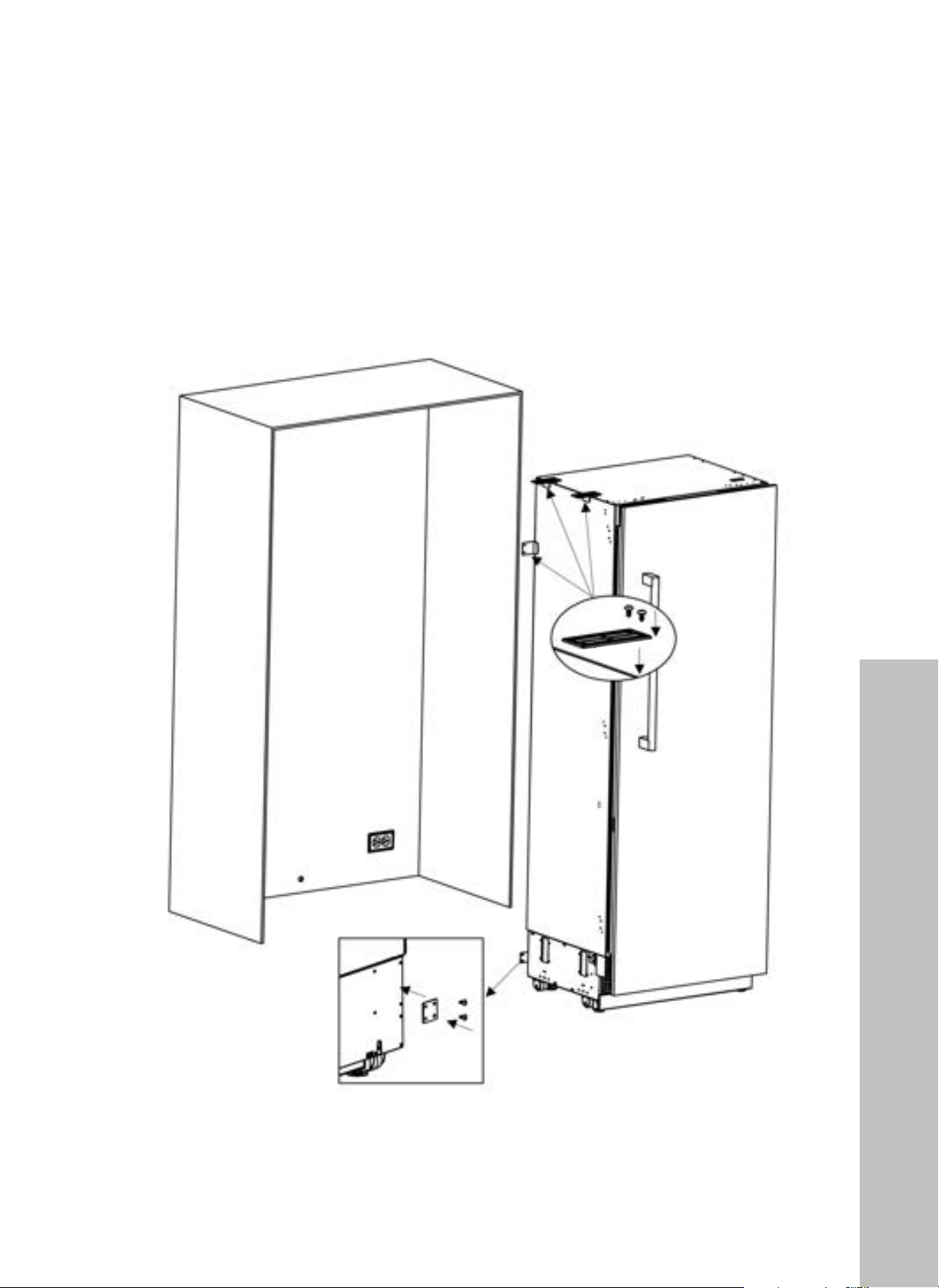
86
DUAL CABIN INSTALLATION
MOUNT UPPER BRACKETS AND LOWER BACK BRACKET
TO CONNECT REFRIGERATORS OR FREEZERS
1. Screw (page 85, Item No. 3) the metal mounting brackets (page 85, Item No. 4)
that are going to be used to connect two refrigerators together to the locations as outlined
in the below figure.
!"#$%&'#(%)*! !
)#"
"
C..#,1)*+%.1'%0#2.'*'(2%#*$%,"**',.)*+%&(#,G'.%
!
,@:8L"`$a">78"G32>848:2"`%a">73>"3:8";094;">0"/8"M285">0"@0448@>">L0":8K:9;8:3>0:2">0;8>78:" "
>0">78"10@3>9042"270L4"94">78"K9;M:8<" "
+
+
+
+
+
+
+
+
+
+
+
+
+
J0448@>94;"/:3@P8>"`Aa
!
G32>848:"
!"#$%&'#(%)*! !
)#"
"
C..#,1)*+%.1'%0#2.'*'(2%#*$%,"**',.)*+%&(#,G'.%
!
,@:8L"`$a">78"G32>848:2"`%a">73>"3:8";094;">0"/8"M285">0"@0448@>">L0":8K:9;8:3>0:2">0;8>78:" "
>0">78"10@3>9042"270L4"94">78"K9;M:8<" "
+
+
+
+
+
+
+
+
+
+
+
+
+
J0448@>94;"/:3@P8>"`Aa!
G32>848:"
Metal mounting bracket
Metal mounting
bracket
Connecting Brackets
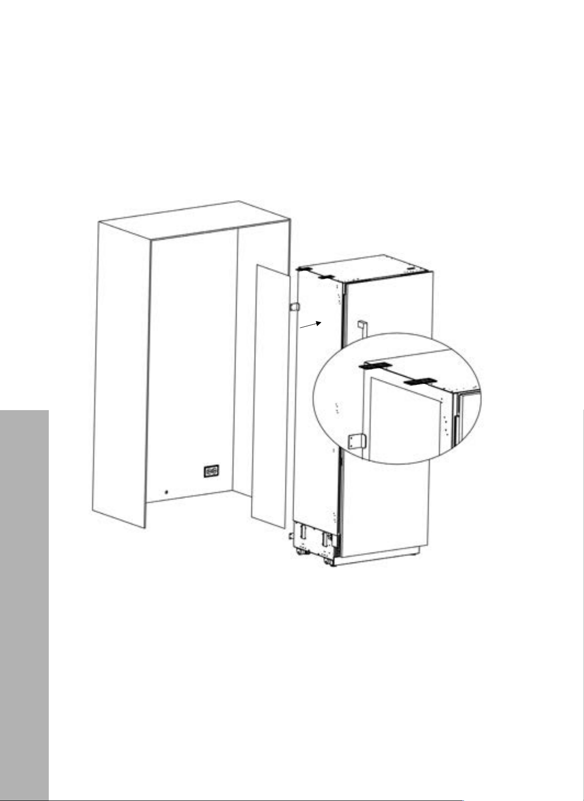
87
DUAL CABIN INSTALLATION
MOUNT UPPER BRACKETS AND LOWER BACK BRACKET
TO CONNECT THE UNITS
1. Stick the adhesive foam divider (page 85, Item No. 1) to the side panel so that the
sponge remains in between two cabins.
!"#$%&'#(%)*! !
)$"
"
+
!
,>9@P">78"=42M13>904",?04;8"`!a">0">78"2958"?3481"20">73>">78"2?04;8":8.3942"94"/8>L884">L0"@3/942<" "
+
+
+
+
+
+
+
+
+
+
+
+
+
+
+
+
+
+
+
+
+
+
+
+
+
+
+
+
+
+
+
+
+
+
+
+
+
+
+
+
+
+
+
+
+
+
+
+
+
+
+
+
+
+
+
+
+
+
+
!"#$%&'#(%)*! !
)#"
"
C..#,1)*+%.1'%0#2.'*'(2%#*$%,"**',.)*+%&(#,G'.%
!
,@:8L"`$a">78"G32>848:2"`%a">73>"3:8";094;">0"/8"M285">0"@0448@>">L0":8K:9;8:3>0:2">0;8>78:" "
>0">78"10@3>9042"270L4"94">78"K9;M:8<" "
+
+
+
+
+
+
+
+
+
+
+
+
+
J0448@>94;"/:3@P8>"`Aa!
G32>848:"
Connecting the Units
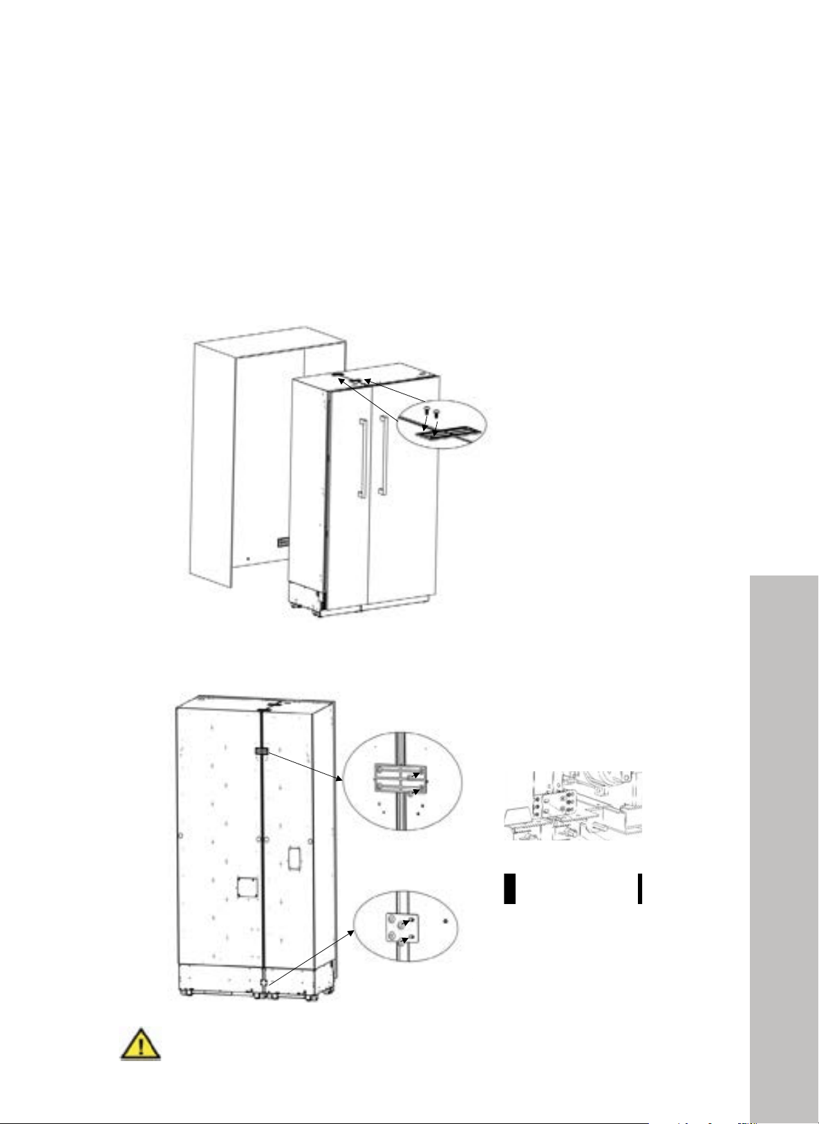
88
DUAL CABIN INSTALLATION
PUSH INTO PLACE
1. Bring the two units side by side.
2. After making sure that they are in alignment, screw the metal mounting brackets (page
85, Item No. 4) to the other refrigerator.
3. Screw the metal mounting bracket (page 85, Item No. 2) on the back and screw
connecting bracket (page 85, Item No. 6) on the front.
!"#$%&'#(%)*! !
)%"
"
+
!
U:94;">78">L0":8K:9;8:3>0:2"2958"/-"2958<" "
AK>8:".3P94;"2M:8">73>">78-"3:8"94"319;4.84>\"2@:8L"K32>848:2"`%a">0">78"0>78:":8K:9;8:3>0:<" "
+ ++++++++-./'0+."##'.(%#1+2/).3'(+4+567+"#+(8'+2).3+)#&+9./'0+."##'.(%#1+2/).3'(+:+5;7+"#+(8'+$/"#(<+
+
+
+
+
+
+
+
+
+
+
+
+
+
+
+
+
+
+
+
+
+
+
+
+
+
+
+
+
+
+
+
+
+
+
+
+
+
+
+
+
+
+
+
+
+
+
+
+
+
+
+
+
+
+
+
+
+
J0448@>94;"/:3@P8>"`Aa"
04">78"/3@P!
J0448@>94;"/:3@P8>"`Ua"
04">78"K:04>!
Connecting bracket (B)
on the front
Connecting bracket (A)
on the back
WARNING
Units are top-heavy. Take care when installing the product; two-person assembly
is highly recommended.
Push Into Place
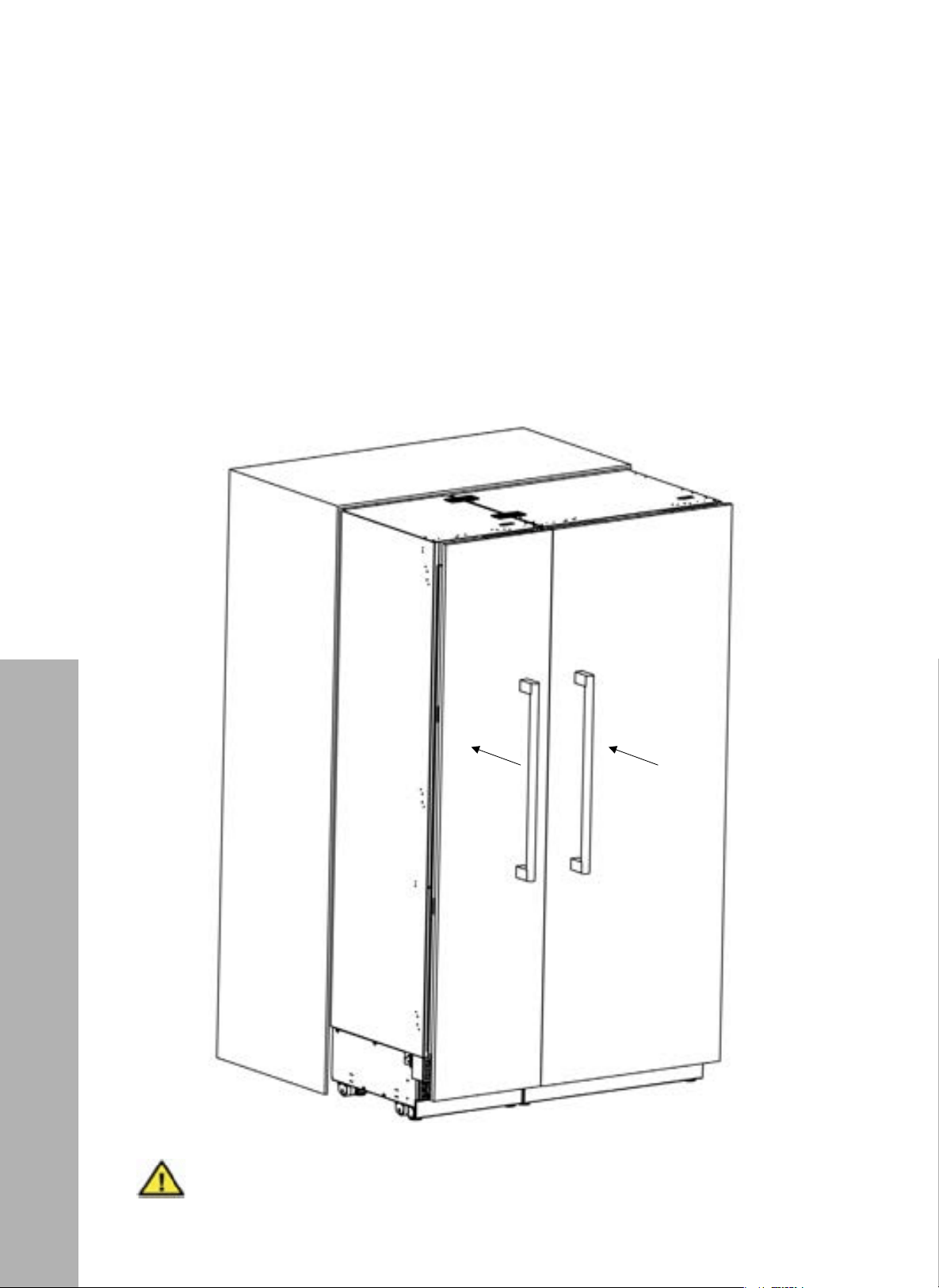
89
DUAL CABIN INSTALLATION
PUSH INTO PLACE
1. Before pushing into place, install the necessary power and water connections and anti-tip
brackets (refer to directions earlier in this manual).
2. Uninstall the door on the left unit and re-orientate the inside drawers and hinges so the
handle to the door pulls out to the left — opposite of the door on the right unit — then
reinstall the door (refer to directions earlier in this manual).
3. Carefully push the dual unit into the cabinet and ensure there is a 1/8" (3 mm) gap on
either side.
!"#$%&'#(%)*! !
)&"
"
+
S3P8"?0L8:"345"L3>8:"@0448@>9042"0K">78":8K:9;8:3>0:"32"8_?139485"/8K0:8<" "
IM27">78":8K:9;8:3>0:2"94>0">78"@3/94<" "
+
+
+
+
+
+
+
+
+
+
+
+
+
+
+
+
+
+
+
+
+
+
+
+
+
+
+
+
+
+
+
+
+
+
+
+
+
+
+
+
+
+
+
+
+
+
+
+
+
+
+
+
+
+
+
+
+
WARNING
Refrigerators are top-heavy and weigh 345 lb (156 kg). The dual unit weighs
close to 700 lb (318 kg). Take care when installing the product; two-person
assembly is highly recommended.
Push Into Place
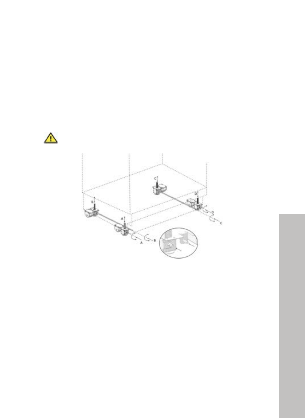
90
DUAL CABIN INSTALLATION
ADJUSTING THE HEIGHT
• With the dual unit now pushed into the cabinet, the feet need to be raised in order to secure
the product to the anti-tip brackets.
• You may use a drill with a 1/4" hex bit or a socket wrench to adjust leg height; we
recommend using a socket wrench by hand to avoid the risk of stripping the legs.
• Do not use an impact drill to adjust the feet; doing so may cause damage.
WARNING
It's important to raise the front feet first to reduce risk of the appliance falling
frontward, which would increase the risk of injury.
A/D — Turn the key clockwise to lift the front
B/C — Turn the key clockwise to lift the rear
Leveling Both Units
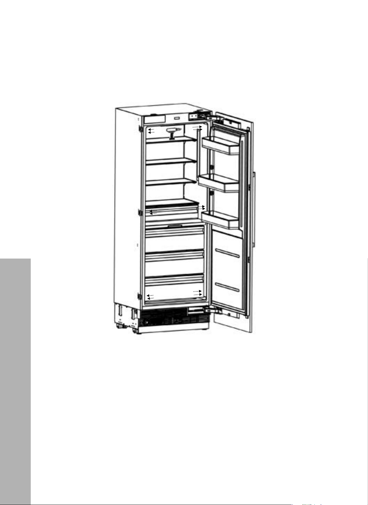
91
DUAL CABIN INSTALLATION
SCREWING THE CABINET BRACKET ON THE CABINET SIDE WALL
1. Attach the brackets to the cabinet with 12 screws.
!"#$%&'#(%)*! !
)("
"
<,('F)*+%.1'%&(#,G'.%04(*).4('%"*%.1'%,#&)*%2)$'%F#77%
A>>3@7">78"/:3@P8>"KM:49>M:8">0">78"KM:49>M:8"L9>7"!#2@:8L2<"
"
"
"
"
"
"
"
"
"
/
"
"
"
"
"
"
"
"
"
"
"
"
"
"
"
"
"
"
"
"
"
"
"
"
"
"
"
"
"
"
"
"
"
"
"
"
"
"
"
"
"
"
"
"
"
"
"
"
"
"
Cabinet Brackets
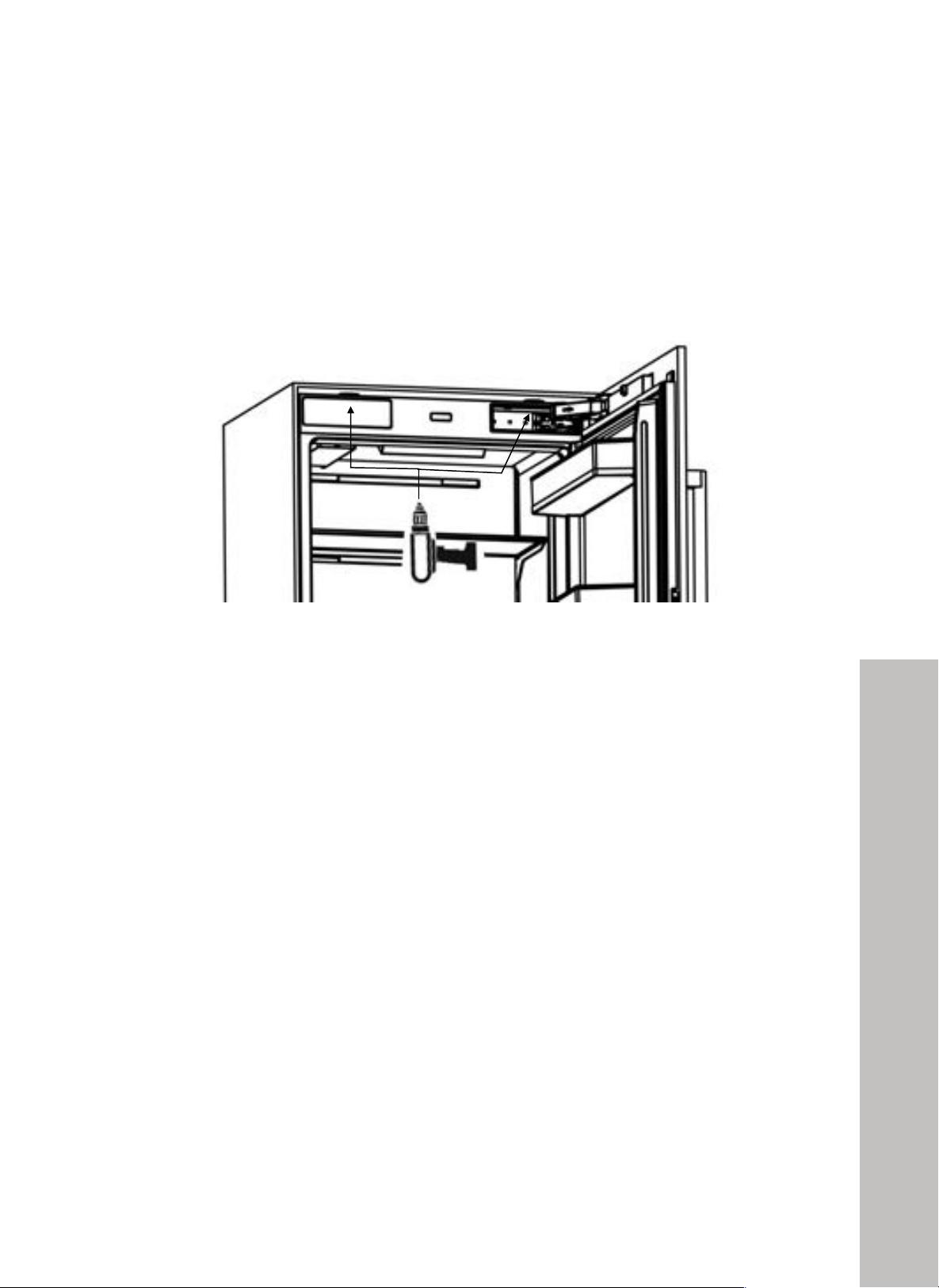
92
DUAL CABIN INSTALLATION
SECURING THE DUAL UNIT INTO THE CABINET CUTOUT
1. Using the remaining cabinet mounting bracket screws provided with your parts kit, secure
the right unit to the cabinet — 4 screws on top and 6 on each side.
2. After the right unit is secured into the cabinet, secure the left unit into the cabinet in the same
manner — 4 screws on top and 6 on each side.
!"#$%&'#(%)*! !
))"
"
<,('F)*+%.1'%&(#,G'.%04(*).4('%"*%.1'%,#&)*%."-%F#77%
•! A>>3@7">78"/:3@P8>"KM:49>M:8">0">78"KM:49>M:8"L9>7"%2@:8L2<"
"
"
!
Securing the Unit
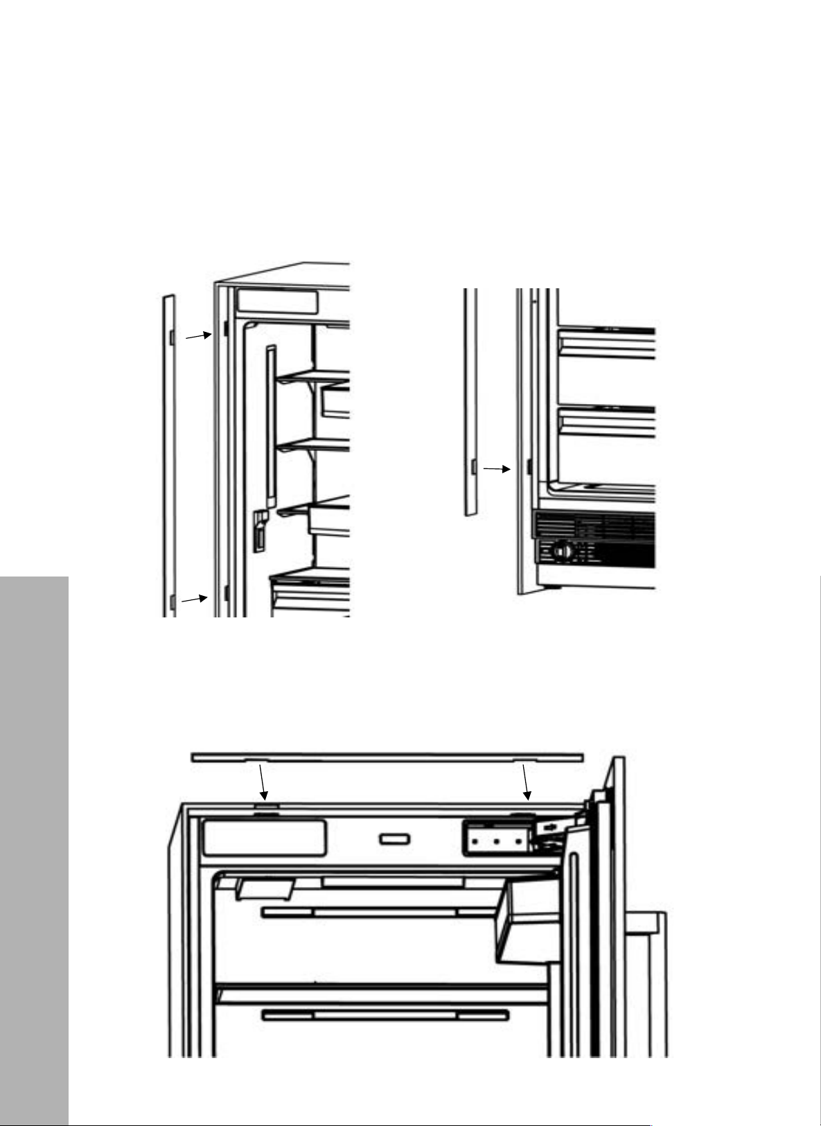
93
DUAL CABIN INSTALLATION
ATTACHING THE TRIM PIECES
1. Attach the side trim pieces provided with the parts kit onto the outer sides of each unit,
covering the cabinet mounting brackets as shown below.
2. Attach the top trim pieces provided with the parts kit onto the tops of both units, covering the
cabinet mounting brackets as shown below.
Attaching the Trim Pieces
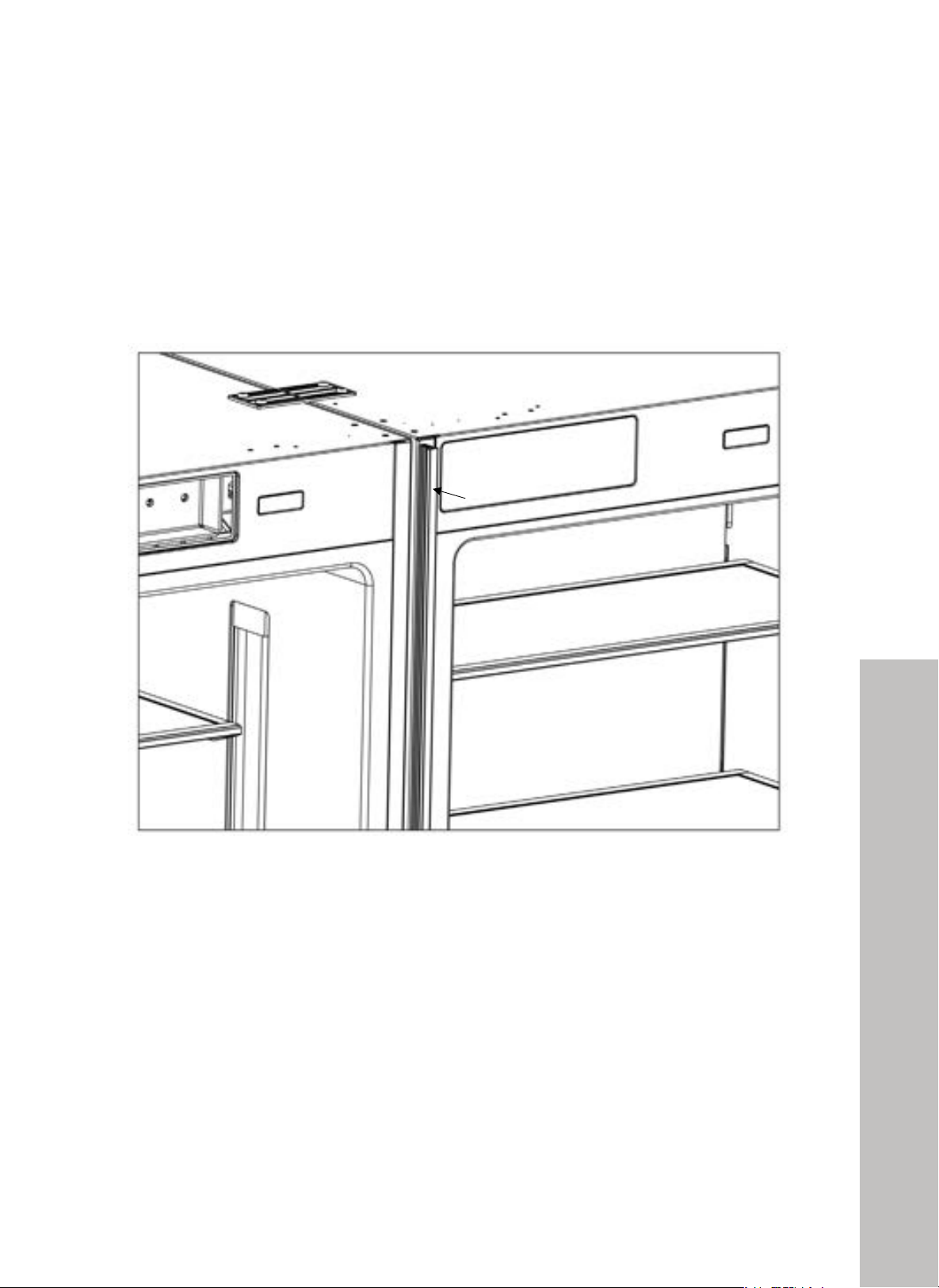
94
DUAL CABIN INSTALLATION
INSTALL DIVIDER TRIM
1. After ensuring both units are flush and everything is level, insert the center divider trim (Item
No. 5 in the dual unit parts list) between both units and lightly pound into place with the
back of your fist.
!"#$%&'#(%)*! !
*+"
"
A>>3@7">78".95518"@10294;"?3:>2"`>:9."KM:49>M:8".95518"=>8."E0&a"/8>L884">L0":8K:9;8:3>0:2<"
+
+
+
+
+
+
+
+
+
+
+
+
+
+
+
+
+
+
+
+
+
+
+
+
+
+
+
+
+
+
+
+
+
+
+
+
+
+
+
+
+
+
+
+
+
+
+
+
+
+
+
+
+
+
+
+
+
+
+
+
"
Installing Divider Trim
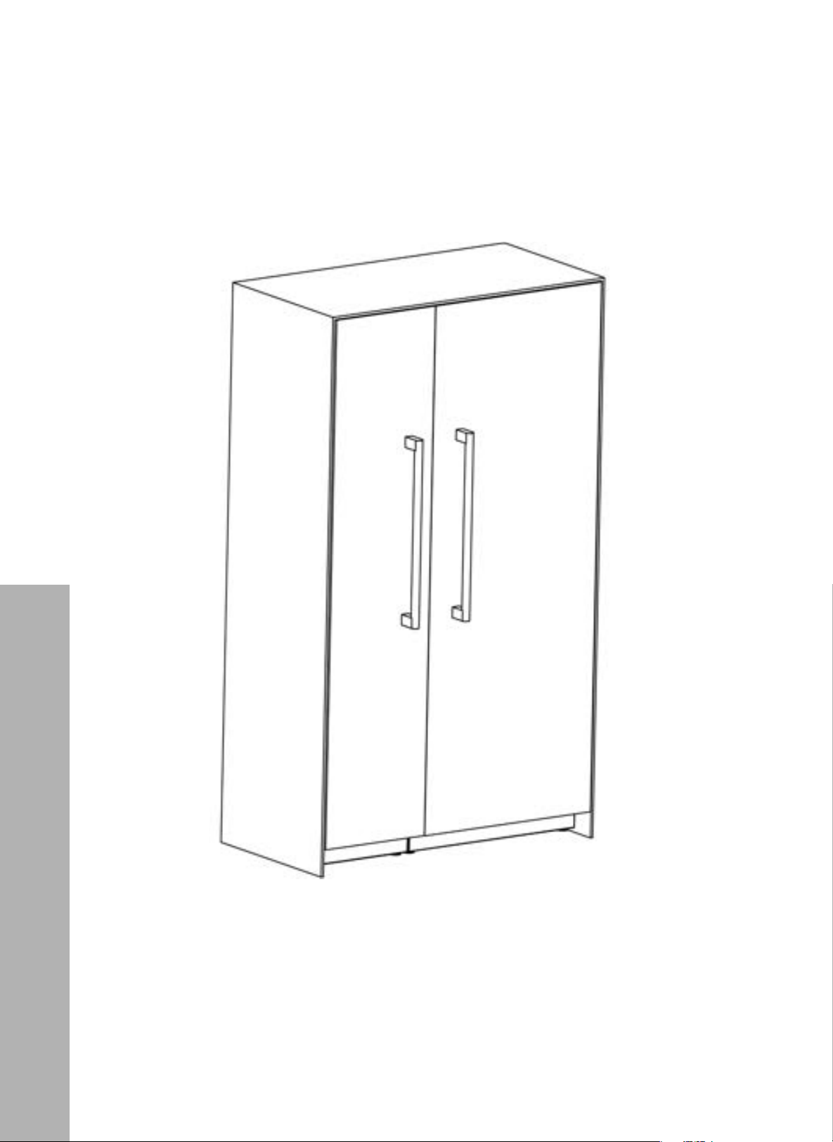
95
DUAL CABIN INSTALLATION
INSTALLATION COMPLETE
IMPORTANT: Refer to this Installation Manual as needed for other installation procedures.
!"#$%&'#(%)*! !
*!"
"
]0M"@34"288"?:8Q90M2"?3;82"K0:"0>78:"942>3113>904"?:0@85M:82<+
+
+
+
+
+
+
+
+
+
+
+
+
+
+
+
+
+
+
+
+
+
+
+
+
+
+
+
+
+
+
+
+
+
+
+
+
+
+
+
+
+
+
+
+
+
+
+
+
+
Installation Complete

WARRANTY
COVERAGE
ZLINE Kitchen and Bath ("ZLINE") column refrigerators and freezers have a two year parts and
service warranty and a five year parts warranty on the unit's sealed cooling system.
ZLINE warranty periods begin from the original date of product delivery and solely cover the
original purchaser of the product, delivered new and in its original carton. The limited warranty
covers all parts and labor for necessary repairs if any part of the product, or the product itself,
proves to be defective in materials or workmanship.
The product must be deemed serviceable via troubleshooting with the ZLINE Customer Experience
team. All service on ZLINE products under warranty must be performed by ZLINE-approved and
ZLINE-certified service providers unless otherwise specified by ZLINE. Service will be provided
during normal business hours.
Products must be unobstructed and accessible to the service provider at the time of service.
ZLINE’s liability is limited to the original purchase price of the product. Additional injuries, losses,
damages, or other inconveniences caused by product malfunction or defects in materials are not
covered under the terms of this warranty.
TERMS
ZLINE warranties apply only to the original purchaser of a ZLINE product installed for normal
residential use. This is defined as a single-family, residential dwelling in a non-commercial setting.
Any warranty claim stemming from installation, operation, or any other use within a commercial
setting is not covered under this limited warranty. Commercial settings include, but are not limited
to: schools, churches, hotels, restaurants, vacation rentals such as Airbnb, daycare centers,
private clubs, fire stations, common areas in multi-family dwellings, nursing homes, food service
locations, and institutional food service locations such as hospitals or correctional facilities.
This warranty is non-transferable and will not under any circumstance be extended based on the
date of installation — the warranty period takes effect from the date of delivery and only covers
the original purchaser. The warranty applies only to products installed in the contiguous United
States and the District of Columbia.

Failure to secure certified warranty service per these terms will result in a forfeiture of the
remaining warranty. Out-of-pocket payments will not be reimbursed unless prior approval is
received from ZLINE and/or ZLINE-certified service contract partners. Unapproved out-of-
pocket payments for service will not be reimbursed. All warranty procedures must be followed to
maintain warranty coverage.
If a product qualifies within the service window provided under these warranty terms, and ZLINE
is unable to repair the product or a defective part of the product after a reasonable number of
attempts, ZLINE reserves the right to offer to replace the defective part or the product or provide
the original purchaser a full refund of the purchase price of the product (not including installation,
removal, or other charges that were not included in the original purchase price).
The original purchaser of the product must provide the original proof of purchase, including the
purchase date, when filing a claim to obtain replacement parts, service, or refunds. Additionally,
the original purchaser of the product must provide the serial number of the product when filing a
claim to obtain replacement parts, service, or refunds.
This warranty shall not apply to any ZLINE product in which the original factory serial number
has been removed, altered, or cannot be readily determined for any reason. Further, ZLINE is
not responsible for damage resulting from, but not limited to: shipment, delivery, or improper
installation; negligence or improper maintenance, misuse, or abuse of the product; unauthorized
alteration, modification, or tampering with the product; accident, fire, floods, pest infestations,
pandemics, natural disasters, or any other unpreventable or unexplained acts of nature,
commonly referred to as “acts of God”; flare-up fires or damages caused by improper electric
supply, electrical line current, voltage, or power surges; and service to correct installation not
in accordance with the instructions contained in ZLINE’s product manuals and/or with local
government codes.
In the event service is dispatched, and it is discovered that the reported issue is not covered under
warranty based on the disclaimers above, the customer will be responsible for all service fees.
Failure to pay these fees will result in the forfeiture of remaining warranty coverage.
WARRANTY
Information contained within ZLINE’s installation and user manuals, in addition to product
information included on ZLINE’s website and all related digital listings, do not cover every possible
condition and situation that may occur during the installation or operation of ZLINE products.
ZLINE reserves the right to make changes at any time to its products when considered safe,
necessary, and useful. Always check the ZLINE website for the most up-to-date version of its
product manuals: www.zlinekitchen.com/pages/manuals.
Do not install or operate any ZLINE product if it has missing or broken parts or if it arrives damaged
due to shipping. If ZLINE products arrive damaged, contact ZLINE Customer Experience at
1-614-777-5004 for help. Failure to report a damaged appliance prior to installation or
oper
ation may void th
e warranty.
ZLINE disclaims responsibility for damage or injury caused by improper installation or use of
any of its products. ZLINE is under no obligation, by law or otherwise, to provide concessions,
including repairs, prorates, rebates, discounts, or replacements, once the warranty has expired.
SERIAL NUMBER LOCATION
The rating tag shows the model and serial number of your
refrigerator. The product label and rating tag are located on the
left-hand side of the cabinet. The tag is visible when the
refrigerator door is open. Do not remove permanently affixed
labels, warnings, or plates from the product. This will void
the warranty.
WARRANTY
SERVICE
For warranty service, please contact our Customer Service team at
1-614-777-5004 or visit www.zlinekitchen.com/contact to utilize our
online Customer Experience Portal.
Scan the QR code to view the most up-to-date version of our user manual
and installation manual.
Need to purchase a part or accessory for your ZLINE product?
Visit www.zlineparts.com, ZLINE's official parts distribution partner.
WARRANTY