Installation Instructions
Slide-in Electric Range
R-REH304SS
Owner: Please retain these instructions for future reference.
For residential use only.
Installer: Please leave these instructions with this unit for the owner.
Important: Read and save these isntructions.
Rev.25.05

Table of Contents
Range Safety ............................................................................................................. 3
Anti-Tip Device .................................................................................................. 5
Installation Requirements ....................................................................................... 6
Tools and Parts .................................................................................................. 6
Location Requirements..................................................................................... 8
Product Dimensions ....................................................................................... 10
Clearances ....................................................................................................... 11
Power Supply Location ................................................................................... 13
Electrical Requirements .................................................................................. 14
Installation Instructions.......................................................................................... 18
Remove Old Appliance .................................................................................. 18
Unpack Range ................................................................................................. 20
Install Rear Rubber Pads ................................................................................. 21
Install Anti-Tip Device ..................................................................................... 22
Electrical Connection ...................................................................................... 26
Connecting the Power Cord/Conduit ................................................... 26
4-Wire Connection .................................................................................. 29
3-Wire Connection .................................................................................. 31
Install/Remove Control Knobs ....................................................................... 33
Install/Remove Oven Door Handle ............................................................... 34
Removing/Assembling Oven Door ............................................................... 37
Removing/Assembling Storage Drawer ....................................................... 39
Complete Installation ..................................................................................... 40
Placement and Leveling Range .............................................................. 40
Verify Anti-Tip Bracket Engagement ..................................................... 42
Checking Operation of the Surface Heating Elements ........................ 44
Checking Operation of the Oven........................................................... 45
2
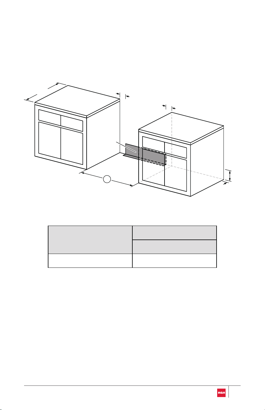
Range Safety
Read All Instructions Before Using the Appliance
Your safety and the safety of others are very important.
We have provided many important safety messages in this manual and on
your appliance. Always read and obey all safety messages.
WARNING
You can be killed or seriously injured if you don't
follow instructions.
This is the safety alert symbol.
This symbol alerts you to potential hazards that
can kill or hurt you and others.
All safety messages will follow the safety alert
symbol and either the word "WARNING" or
"CAUTION." These words mean:
CAUTION
A potentially hazardous situation which, if not
avoided, could result in minor or moderate injury.
All safety messages will tell you what the potential hazard is, tell you how to
reduce the chance of injury, and tell you what can happen if the instructions
are not followed.
California Proposition 65 Warning
WARNING: Cancer and Reproductive Harm - www.P65Warnings.ca.gov.
3
WARNING
• This appliance is intended for normal residential use. It is not approve d
for commercial use, outdoor installation, or any other application no t
specifically allowed by this manual.
• This appliance requires connection to a 3-prong or 4-prong, 240V AC
single-phase (split-phase), 60Hz grounded electrical source dedicate d to
the appliance. When installed, appliance must be electrically ground ed
in accordance with local codes or, in the absence of local codes, with th e
National Electrical Code, NFPA 70 or the Canadian Electric Code, CS A
C22.1-02.
• Proper installation is the responsibility of the installer. Any adjustmen t
and service should be performed only by qualified oven installers o r
service technicians. The manufacturer is not responsible for any injury o r
damage that may result from incorrect or defective installation by
unauthorized personnel.
• Product failure due to improper installation is not covered unde r
warranty.
• Do not use a steam cleaner to clean the appliance.
• This appliance is not intended to be operated with separate remo te
control system.
4
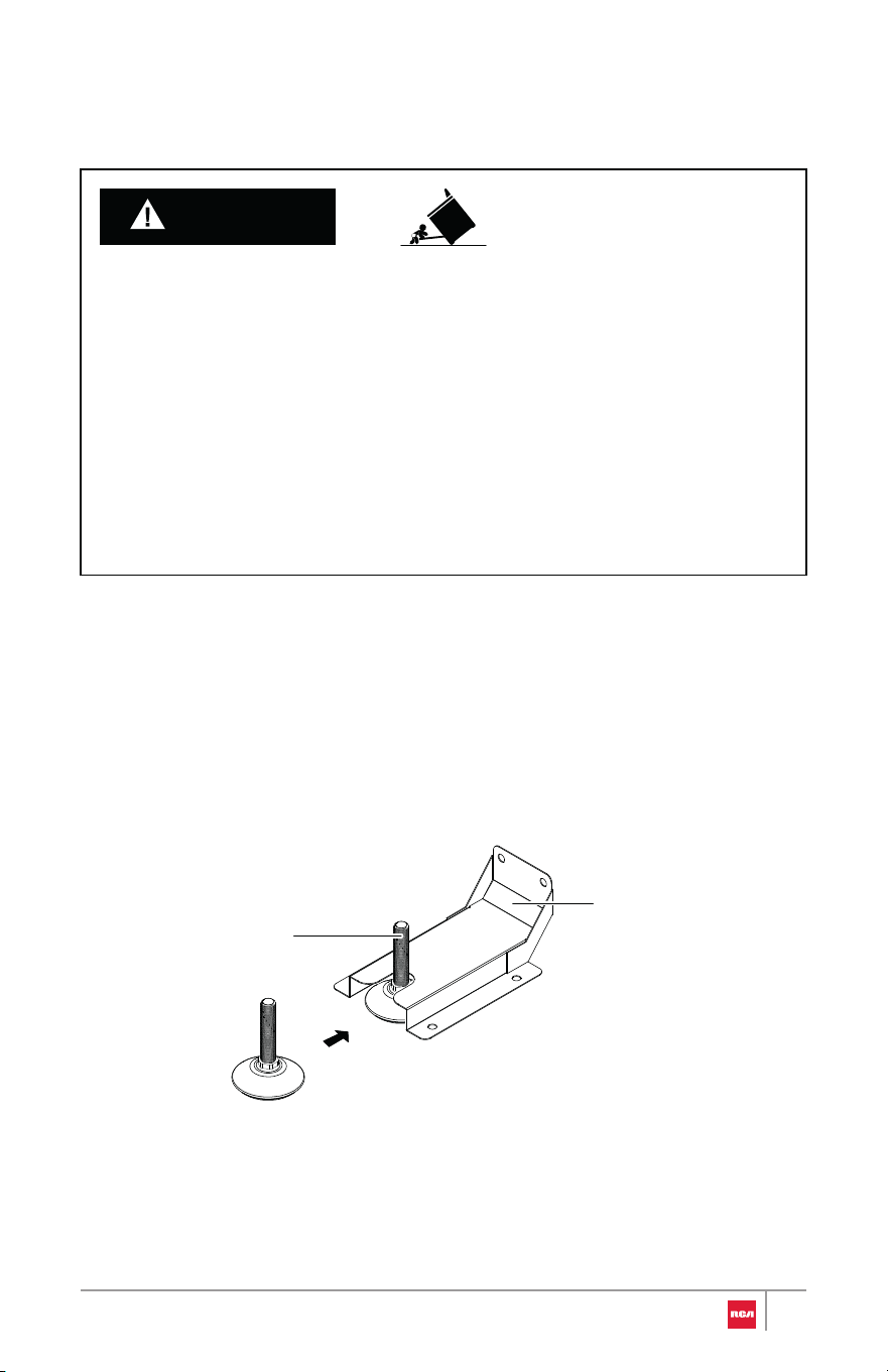
Anti-Tip Device
Tip Over Hazard
Making sure the anti-tip bracket is installed:
• Slide range forward.
• Look for the anti-tip bracket securely attached to floor or wall.
• Slide range back and make sure rear range foot is under anti-tip bracket.
• A child or adult can tip the range and be killed.
• Install anti-tip bracket to floor or wall per installation instructions.
• Slide range back so rear range foot is engaged in the slot of the anti-tip
bracket.
• Re-engage anti-tip bracket if range is moved.
• Do not operate range without anti-tip bracket installed and engaged.
• Failure to follow these instructions can result in death or serious burns to
children and adults.
WARNING
Rear range foot
Anti-tip bracket
5
Installation Requirements
Tools and Parts
Gather the required tools and parts before starting installation. Read and
follow the instructions provided with any tools listed here.
Tools Needed
Parts Need
ed
• Adjustable wrench or pliers
• Marker or pencil
• Safety glasses
• Gloves
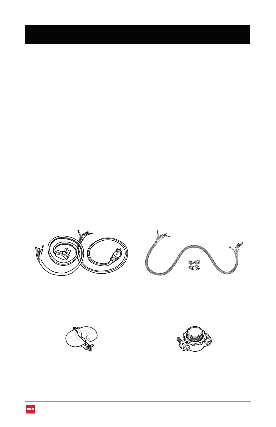
4-Wire or 3-wire power cord
(UL approved 40 or 50 AMP)
4-wire or 3-wire conduit and
wire connectors (UL listed)
or
or
If connecting using power cord:
Strain relief (UL listed)
If connecting using conduit:
Conduit connector (UL listed)
6
• Tape measure
• Phillips screwdriver
• Level
• Drill and drill bit (for anti-tip
bracket installation)
7
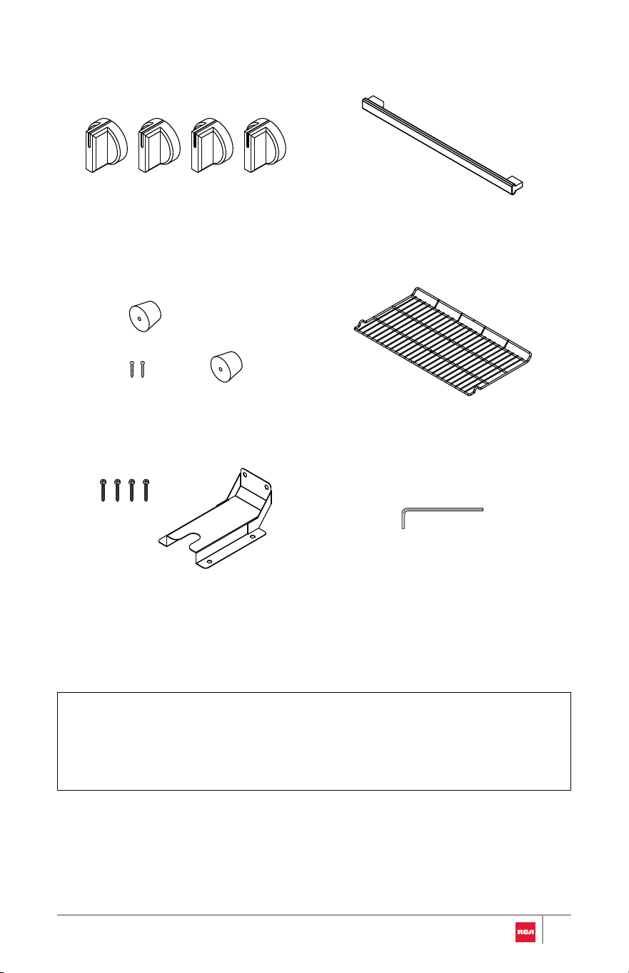
Parts Supplied
Control knobs
30" Model: R-REH304SS (4)
Oven door handle with set screws
Rear rubber pads (2) Oven racks (2)
Hex key
Anti-tip bracket with ST5 x 40 mm
mounting screws
Note:
• To purchase these replacement parts or any other accessories, please
visit www.fgsbrands.com/rca-parts/ or reference the contact information
at the end of this manual.
Location Requirements
IMPORTANT: Observe all governing codes and ordinances. Do not obstruct
flow of combustion and ventilation air.
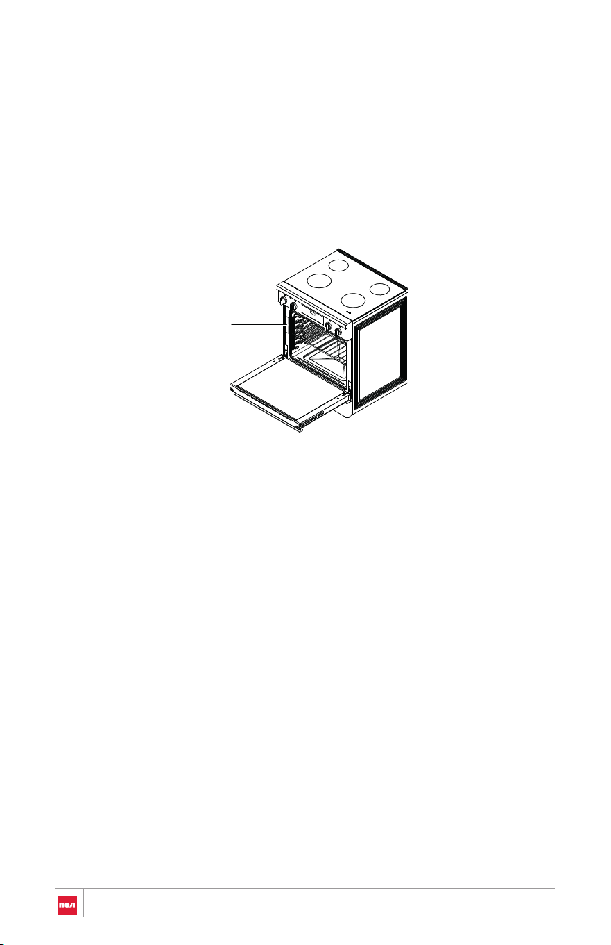
• It is the installer's responsibility to comply with installation clearanc es
specified on the model/serial/rating plate. The plate is located behind th e
oven door on the oven frame, and is also on the back panel of the range.
• The range should be located for convenient use in the kitchen.
• Recessed installations must provide complete enclosure of the sides an d
rear of the range.
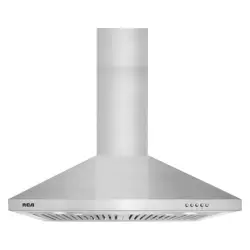
• To eliminate the risk of burns or fire by reaching over heated surface units,
cabinet storage space located above the surface units should be avoide d.
If cabinet storage is to be provided, the risk can be reduced by installing a
range hood or microwave hood combination that projects horizontally a
minimum of 5" (12.7 cm) beyond the bottom of the cabinets.
• All openings in the wall or floor where range is to be installed must b e
sealed.
• Do not seal the range to the side cabinets.
• Cabinet opening dimensions that are shown must be used.
• The anti-tip bracket must be installed.
• Grounded electrical supply is required. See "Electrical Requirements "
section.
• Contact a qualified floor covering installer to check that the floor coverin g
can withstand at least 194°F (90°C).
• Use an insulated pad or 1/4" (0.64 cm) plywood under range if installin g
range over carpeting.
Rating plate
8

IMPORTANT: To avoid damage to your cabinets, check with your builder or
cabinet supplier to make sure that the materials used will not discolor,
delaminate, or sustain other damage. This range has been designed to comply
with the maximum allowable wood cabinet temperatures of 194°F (90°C).
Mobile Home - Additional Installation Requirements
• The installation of this range must conform to the Manufactured Home
Construction and Safety Standard, Title 24 CFR, Part 3280 (formerly the
Federal Standard for Mobile Home Construction and Safety, Title 24, HUD
Part 280). When such standard is not applicable, use the Standard for
Manufactured Home Installations, ANSI A225.1/NFPA 501A or with local
codes.
In Canada, the installation of this range must conform with the current
standards CAN/CSA-A240-latest edition, or with local codes.
Mobile Home Installations Require:
• When this range is installed in a mobile home, it must be secured to the
floor during transit. Any method of securing the range is adequate as long
as it conforms to the standards listed above.
• Four-wire power supply cord or cable must be used in a mobile home
installation. The appliance wiring will need to be revised. See "Electrical
Connection" section.
9
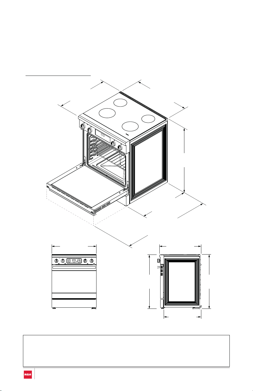
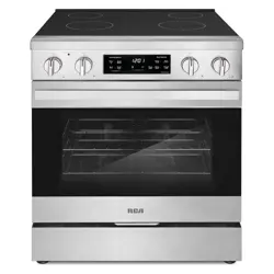
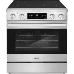
30" Model: R-REH304SS
Note:
Product Dimensions
Your model may appear different from the model depicted. Dimensions given
are maximum dimensions.
• Range can be raised approximately 1" (2.6 cm) by adjusting the leveling
legs.
(68.3 cm)
26 7⁄8 in
(91.9 cm)
36 3⁄16 in
(75.9 cm)
29 7⁄8 in
(68.5 cm)
27 in
(119.0 cm)
46 7⁄8 in
Door fully open
(91.9 cm)
36 3⁄16 in
(91.4 cm)
36 in
(70.5 cm)
27 3⁄4 in
(63.0 cm)
24 13⁄16 in
(75.9 cm)
29 7⁄8 in
10
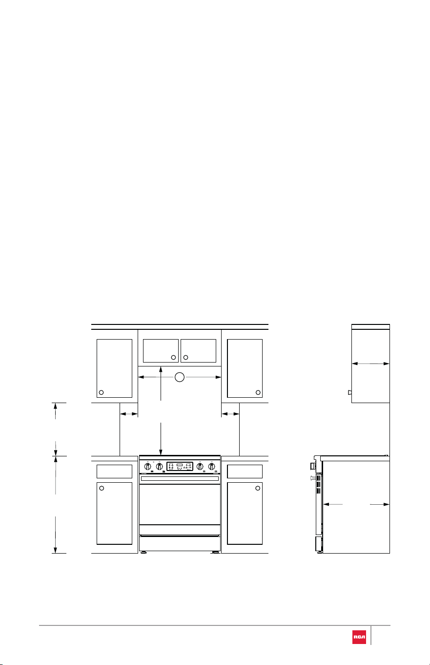
Clearances
Cabinet opening dimensions shown are for 25" (64.0 cm) countertop depth,
24" (61.0 cm) base cabinet depth, and 36" (91.4 cm) countertop height.
IMPORTANT:
Given dimensions are minimum clearances.
• Some cabinet and building materials are not designed to withstand th e
heat produced by the oven for baking and self-cleaning. Check with you r
builder or cabinet supplier to make sure that the materials used will no t
discolor, delaminate or sustain other damage.
• If installing a range hood or microwave hood combination above th e
range, follow the range hood or microwave hood combination installatio n
instructions for dimensional clearances above the cooktop surface.
• Range may be installed next to combustible walls with zero clearance.
13 in
(33 cm)
Overhead
Cabinet
Depth
36 in
(91.4 cm)
18 in
(45.7 cm)
6 in
(15.2 cm)
to right
wall
6 in
(15.2 cm)
to left
wall
24 in
(61 cm)
Lower
Cabinet
Depth
30 in
(76.2 cm)
A
11
Model
A
Horizontal Clearance
30" Model: R-REH304SS 30" (76.2 cm)
Note:
• 30" (76.2 cm) minimum clearance between cooking surface and bottom
of an uncovered wood or metal overhead cabinet.
• 24" (61.0 cm) minimum clearance to top of cooking surface when
bottom of wood or metal overhead cabinet is shielded by not less than
1/4" (0.64 cm) flame retardant millboard covered with not less than No.
28 MSG sheet steel, 0.015" (0.4 mm) stainless steel, 0.024" (0.6 mm)
aluminum or 0.020" (0.5 mm) copper.
• 15" (38.1 cm) minimum clearance from upper cabinet to countertop on
either side of unit.
• When installed in a slide-in cutout, the front of oven door may protrude
beyond the base cabinet.
• Island Installations: Maintain 6" (15.2 cm) minimum clearance from
cutout to back and side edges of countertop.
12
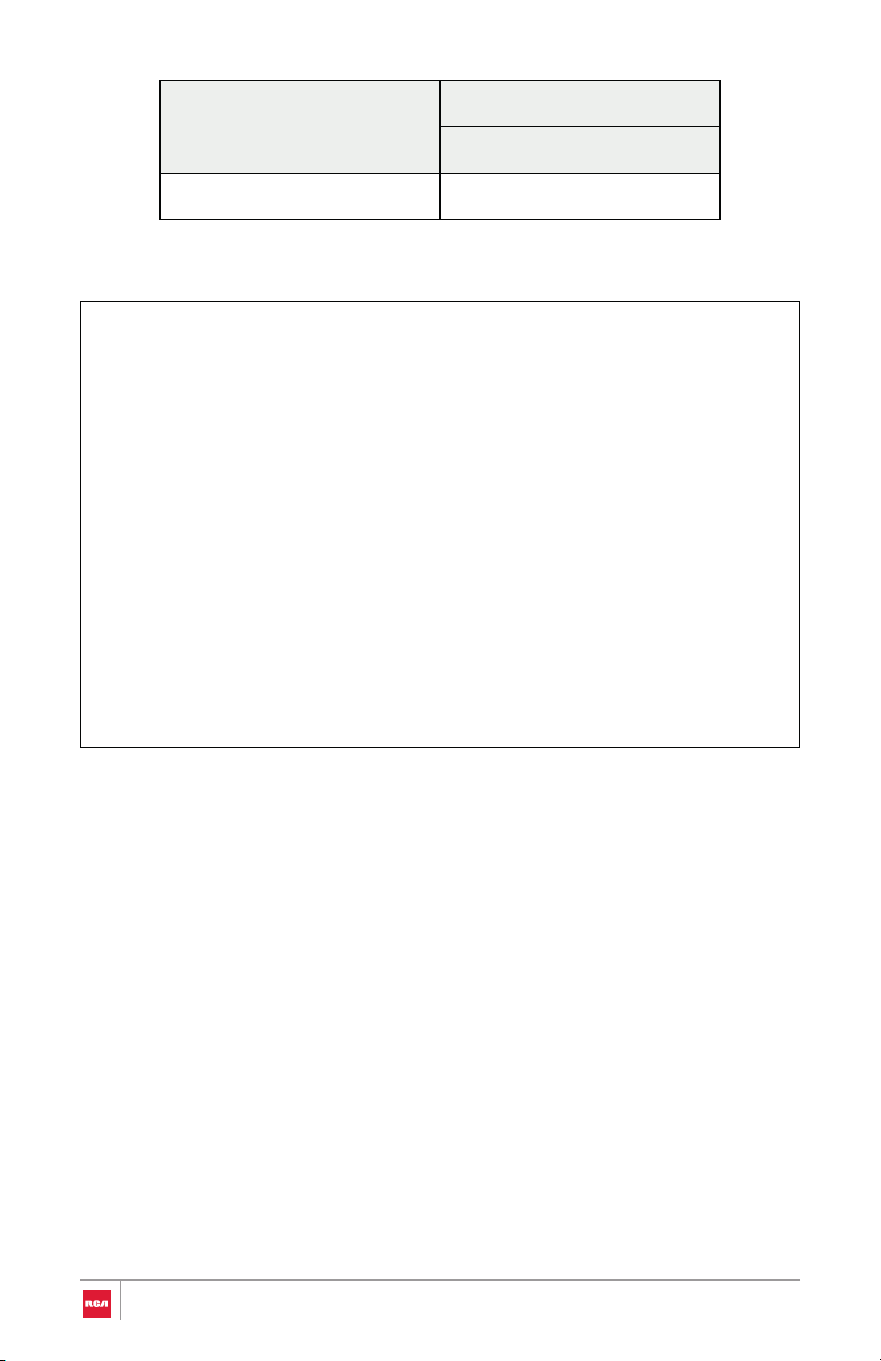
Model
A
Horizontal Clearance
30" (76.2 cm) 30" Model: R-REH304SS
Power Supply Location
IMPORTANT: An electrical outlet in the floor, may be either recessed or
surface mounted, but an electrical outlet in the wall must be recessed to make
the connection.
A
24"
5"
5"
7"
2"
Electric
supply
area
13

Electrical Requirements
WARNING
Electrical Shock Hazard
Electrical Grounding Instructions
• Do not use an extension cord with this appliance.
• Remove house fuse or open circuit breaker before beginning
installation.
• This appliance must be properly grounded.
• All new constructions, mobile homes, recreational vehicles and
installations where local codes do not allow grounding through neutral,
require a 4-conductor UL-listed range cord.
• Check with a qualified electrician if you are in doubt as to whether the
appliance is properly grounded.
National Fire Protection Association
1 Batterymarch Park
Quincy, MA 02169
U.S.A. Only
Be sure that the electrical connection and wire size are adequate and in
conformance with the National Electrical Code, ANSI/NFPA No. 70 - latest
edition and all local codes and ordinances.
A copy of the above code standards can be obtained from:
14

Canada Only
Be sure that the electrical connection and wire size are adequate and in
conformance with the CSA Standard C22.1, Canadian Electrical Code, Part 1 -
latest edition and all local codes and ordinances.
A copy of the above code standards can be obtained from:
Canadian Standards Association
178 Rexdale Blvd.
Toronto, ON M9W 1R3 CANADA
Electrical Connection
If codes permit and a separate ground wire is used, it is recommended that a
qualified electrical installer determine that the ground path and wire gauge are
in accordance with local codes.
WARNING: Improper connection of the equipment-grounding conductor can
result in a risk of electric shock. Check with a qualified electrician or service
technician if you are in doubt as to whether the appliance is properly
grounded. Do not modify the power supply cord plug. If it will not fit the outlet,
have a proper outlet installed by a qualified electrician.
To properly install your appliance, you must determine the type of electrical
connection you will be using and follow the instructions provided for it here.
• This appliance must be supplied with the proper voltage and frequency,
and connected to an individual (dedicated to the appliance), properly
grounded, 40 amp (minimum) branch circuit protected by a circuit breaker
or time-delay fuse.
• A single-phase (split-phase), 3-wire or 4-wire, 120/208 VAC or 120/240
VAC, 60 hertz electrical system must be used. It is the personal
responsibility of the range owner to provide the correct electrical service
for this range.
• Effective January 1, 1996, the National Electrical Code requires that new
construction (not existing) utilize a 4-conductor connection to an electric
range. When installing an electric range in new construction, mobile
home, recreational vehicle, or an area where local codes prohibit
grounding through the neutral conductor.
• This range may be connected by means of a conduit or power cord.
15

• A range cord rated at 40 amps with 125/250 minimum volt range is
required. If a 50 amp range cord is used, it should be marked for use with
1 3/8" (35 mm) diameter connection openings. Care should be taken to
center the cable and strain relief within the knockout hole to keep the
edge from damaging the cable.
• Use only a 3-conductor or a 4-conductor UL-listed range cord. These cords
may be provided with ring terminals on wire and a strain relief device.
• Allow 2 to 3 ft (61.0 to 91.4 cm) of slack in the line so that the range can be
moved if servicing is ever necessary.
• A UL Listed conduit connector must be provided at each end of the power
supply cable (at the range and at the junction box).
• The power supply cord and plug should not be modified. If it will not fit
the outlet, have a proper outlet installed by a qualified electrician.
• Using an extension cord to connect the power is prohibited. Connect the
power cord and plug directly.
• Wire sizes and connections must conform with the rating of the range.
• If using a GFI breaker, the ground wire must be installed correctly to
prevent breaker from tripping. Refer to latest edition of the NEC, NFPA
No. 70, available from the National Fire Protection Association.
• The wiring diagram is located on the back of the range.
If Connecting to a 3-Wire System:
Local codes may permit the use of a UL listed, 3-wire, 250-volt, 40- or 50-amp
range power supply cord (pigtail).
This cord contains 3 copper conductors with
ring terminals or open-end spade terminals with
upturned ends, terminating in a NEMA Type 10-
50P plug on the supply end. Connectors on the
appliance end must be provided at the point
the power supply cord enters the appliance.
This uses a 3-wire receptacle of NEMA Type 10-
50R.
16

If Connecting to a 4-Wire System:
This range is manufactured with the ground connected to the neutral by a link.
The ground must be revised so the green ground wire of the 4-wire power
supply cord is connected to the cabinet.
Grounding through the neutral conductor is prohibited for new branch-circuit
installations (1996 NEC); mobile homes; and recreational vehicles, or an area
where local codes prohibit grounding through the neutral conductor.
When a 4-wire receptacle of NEMA Type 14-50R
is used, a matching UL listed, 4-wire, 250-volt,
40- or 50-amp, range power supply cord
(pigtail) must be used. This cord contains 4
copper conductors with ring terminals or open-
end spade terminals with upturned ends,
terminating in a NEMA Type 14-50P plug on the
supply end.
The fourth (grounding) conductor must be identified by a green or
green/yellow cover and the neutral conductor by a white cover. Cord should
be Type SRD or SRDT with a UL listed strain relief and be at least 4 ft (1.22 m)
long.
17
Installation Instructions
WARNING
IMPORTANT: This appliance shall be installed only by authorized persons and
in accordance with the manufacturer's installation instructions, municipal
building codes, and electrical wiring regulations.
Remove Old Appliance
Fire And Explosion Hazard
If the information in this manual is not followed exactly, a fire or explosion
may result causing property damage, personal injury or death.
WARNING
Electrical Shock Hazard
• Remove house fuse or open circuit breaker to disconnect power before
servicing. Failure to do so can result in death, fire, or electrical shock.
• Installation and service must be performed by a qualified installer,
service agency or the gas supplier.
• WHAT TO DO IF YOU SMELL GAS
- Do not try to light any appliance.
- Do not touch any electrical switch.
- Do not use any phone in your building.
- Clear the room, building, or area of all occupants.
- Immediately call your gas supplier from a neighbor's phone. Follow
the gas supplier's instructions.
• If you cannot reach your gas supplier, call the fire department.
18
WARNING
Excessive Weight Hazard
CAUTION
Laceration, Foreign Object, Crush Hazard
• Use two or more people to move and install oven. Failure to do so can
result in back or other injury.
• When installing, moving, or servicing any appliance, wear prop er
protective equipment, including cut resistant gloves, steel-toed shoe s,
and safety glasses.
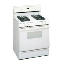
1. For old ranges with gas connection, shut off the gas supply valve to th e
range and leave it off.
2. Shut off the electrical supply to the old range at the breaker box or fus e
box and leave it off until the installation has been completed
3. Move appliance to access and disconnect electrical connection and gas
connection if applicable.
4. Move appliance out of and away from installation space.
19
Unpack Range
WARNING
Excessive Weight Hazard
• Use two or more people to move and install oven. Failure to do so c an
result in back or other injury.
1. Remove shipping materials, tape and film from the range. Do not dispose
of anything until the installation is complete.
2. Remove oven racks and parts package from oven and shipping materials.
3. Using 2 or more people, gently move range close enough but outside its
final installation location to allow for final electrical connections.
Note:
• Do not remove any warning-type labels, the model/serial number
label, or the Tech Sheet that is located on the back of the range.
• Do not use sharp instruments, rubbing alcohol, flammable fluids, or
abrasive cleaners to remove tape or glue. These products can
damage the surface of your range.
• Do not push or pull the range by grabbing the open oven door or
cooktop only. Doing so can result in serious damage to the range.
• Do not lift the range using the cooktop or oven door handle. Doing
so can cause damage and improper operation of the range.
• To reduce the weight of the range while being moved, adjusted,
and installed, leave the oven racks and any other accessories to the
side until they are ready to be installed later in these instructions.
• To further reduce the weight of the range while being moved,
adjusted, and installed, detach the oven door and the storage
drawer from the range. See "Removing/Assembling Oven Door"
and "Removing/Assembling Storage Drawer" sections.
20
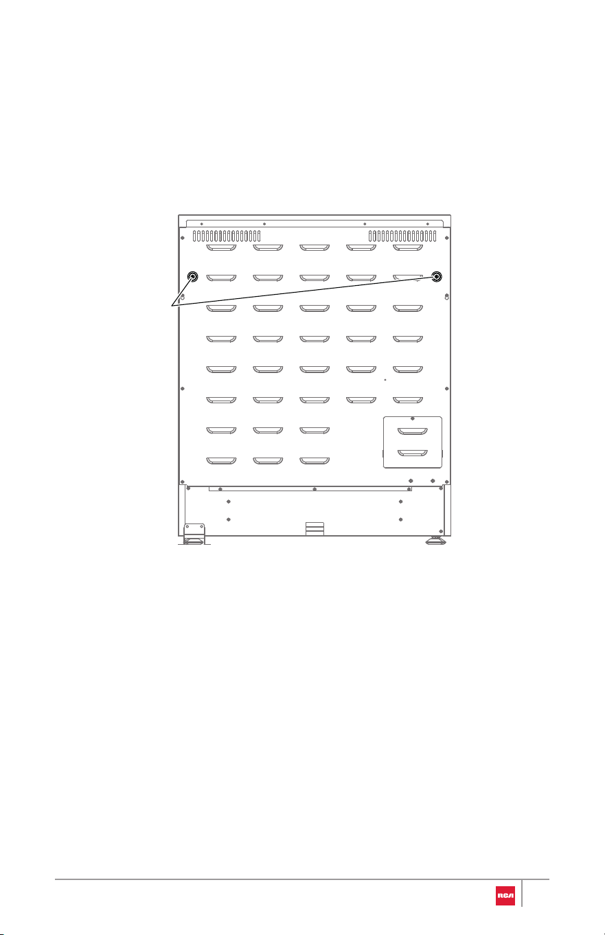
Install Rear Rubber Pads
1. Locate the rubber pads from the parts bag.
2. Install the rubber pads to the back panel of range. Do not overtighten.
Rubber pads
21
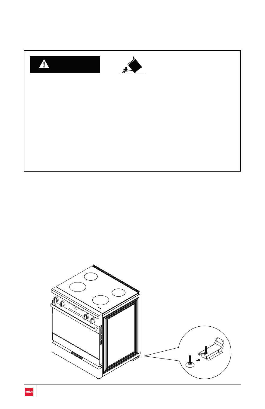
Install Anti-Tip Device
WARNING
Tip Over Hazard
IMPORTANT:
• A child or adult can tip the range and be killed.
• Install anti-tip bracket to floor or wall per installation instructions.
• Slide range back so rear range foot is engaged in the slot of the anti-tip
bracket.
• Re-engage anti-tip bracket if range is moved.
• Do not operate range without anti-tip bracket installed and engaged.
• Failure to follow these instructions can result in death or serious burns to
children and adults.
• An anti-tip bracket is provided with the range.
• The anti-tip bracket uses a rear range foot to secure the range to the floor.
• Attach the anti-tip bracket to the floor or the wall so that the rear range
foot will be centered within the bracket when the range is pushed into its
final position.
22
parts bag.
1. Locate and remove the anti-tip bracket and mounting screws from the
Note:
• Only one anti-tip bracket needs installed.
2. Determine which mounting method to use: floor or wall.
• If you are installing the range in a mobile home, you must secure th e
range to the floor.
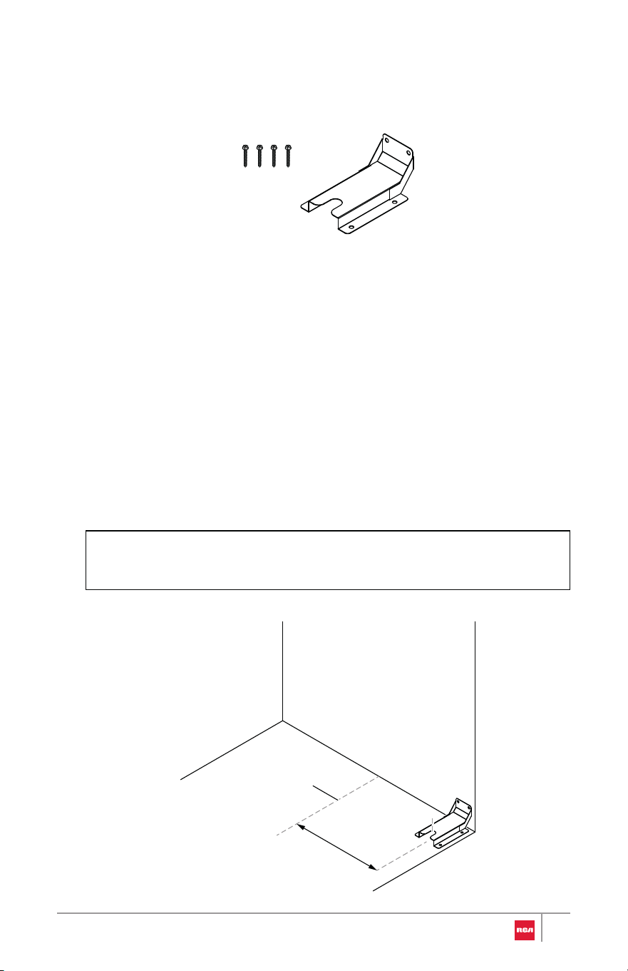
3. Determine and mark centerline of the installation space.
4. Position anti-tip bracket against the wall in the installation space so that
the slot of the bracket is 13" (33.0 cm) from the center line as shown. Th e
anti-tip bracket can be installed on either the rear left or rear right side o f
the installation space.
Centerline
13"
(33.0 cm)
23
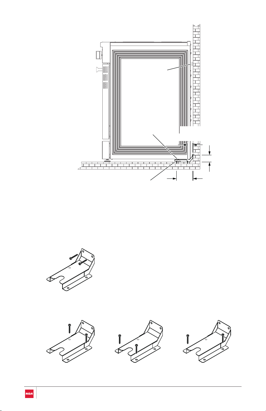
5. Mark two holes that correspond to the anti-tip bracket holes of the
determined mounting metho d.
Wall Mounting
Floor Mounting
Rear holes Front holes Diagonal (2 options)
Rubber pad
Range foot
(5.0 cm)
2 in
(12.4 cm)
4 7⁄8 in
(4.4(4.4
1 3⁄4 in
Anti-tip bracket
24

6. Drill holes specific to your construction.
Wood Construction
• Drill two 1/8" (3 mm) holes where screws are to be located. Screw
must enter wood.
Masonry Construction
• Due to the variety of masonry materials that may be present at
installation site, hardware is not provided for attaching the anti-tip
bracket to masonry.
• If bracket is to be mounted to masonry or ceramic floors, drill two
appropriate holes for 5/16" OD sleeve anchors (with 1/4" bolt - either
hex bolt head or hex nut head) rated for minimum 300lb tension for
the masonry material present at installation site.
7. Install anti-tip bracket.
Wood Construction
• Mount anti-tip bracket to the wall or floor using the two mounting
screws provided.
Masonry Construction
• Mount anti-tip bracket to the floor using two 5/16" OD sleeve anchors
(with 1/4" bolt - either hex bolt head or hex nut head).
25
WARNING
Electrical Shock Hazard
• Remove house fuse or open circuit breaker to disconnect power befo re
servicing.
• This appliance must be properly grounded.
• Do not use an adapter or an extension cord.
• Failure to do so can result in death, fire, or electrical shock.
Electrical Connection
IMPORTANT:
• In
stallation work and repairs should only be performed by a qualified
technician in accordance with all applicable codes and standards. Repairs
and service by unqualified persons could be dangerous and the
manufacturer will not be held responsible.
• Before connecting the appliance to the power supply, make sure that the
voltage and frequency listed on the rating label correspond with the
household electrical supply. This data must correspond to prevent
appliance damage. Consult an electrician if in doubt.
• The oven must connect to a single-phase (split-phase), 3-wire or 4-wire,
120/208 VAC or 120/240 VAC, 60 hertz electrical system. This appliance
must be supplied with the proper voltage and frequency, and connected
to an individual (dedicated to the appliance), properly grounded branch
circuit protected by a circuit breaker or time-delay fuse. It is the personal
responsibility of the oven owner to provide the correct electrical service
for this oven.
• Local codes and ordinances take precedence over these instructions.
Complete electrical connections according to local codes and ordinances.
Connecting the Power Cord/Conduit
1 . Access the range electrical terminal block by removing the screw
attaching the lower terminal block access cover on the back of the range.
26
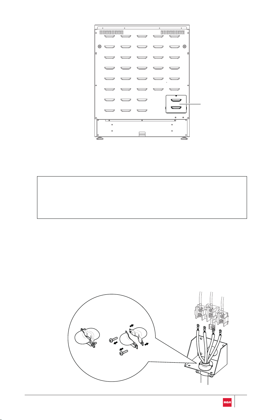
Note:
2. Install the power cord or conduit.
For Power Cord Installations
• Do not install the power cord or conduit without a strain relief. Th e
strain relief bracket must be installed before replacing the terminal
block access cover.
• Hook the strain relief over the power cord hole below the terminal
block. Insert the power cord through the strain relief and tighten i t.
Allow enough slack to easily attach the cord terminals to the terminal
block.
Terminal block
access cover
27
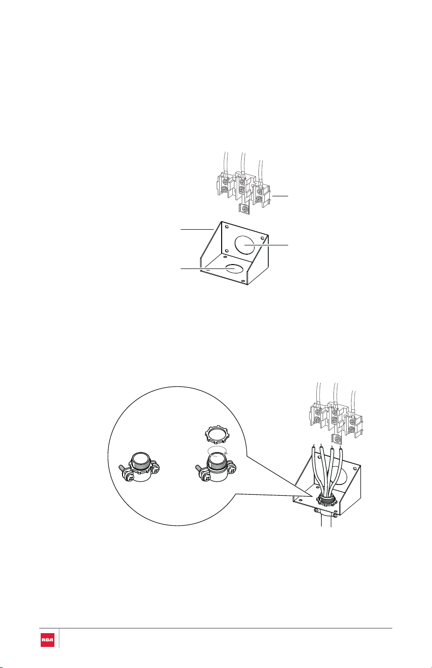
For Conduit Installations
• Strip outer covering back 3" (7.6 cm) to expose wires.
• Strip the insulation back 3/8" (1.0 cm) from the end of each wire.
• Unscrew and align the cord/conduit connection bracket so that th e
smaller 11⁄8" (2.8 cm) conduit hole is at the bottom, the replace the
bracket.
• Insert the conduit strain relief in the conduit hole below the terminal
block. Install the conduit through the body of the strain relief an d
fasten the strain relief with its ring. Allow enough slack to easily attac h
the wires to the terminal block.
3. Complete installation following instructions for your type of electrical
connection:
• 4-wire (recommended)
• 3-wire (if 4-wire is not available)
13⁄8" (3.5cm)
power cord hole
11⁄8" (2.8 cm)
conduit hole
Cord/conduit
connection bracket
Terminal block
28
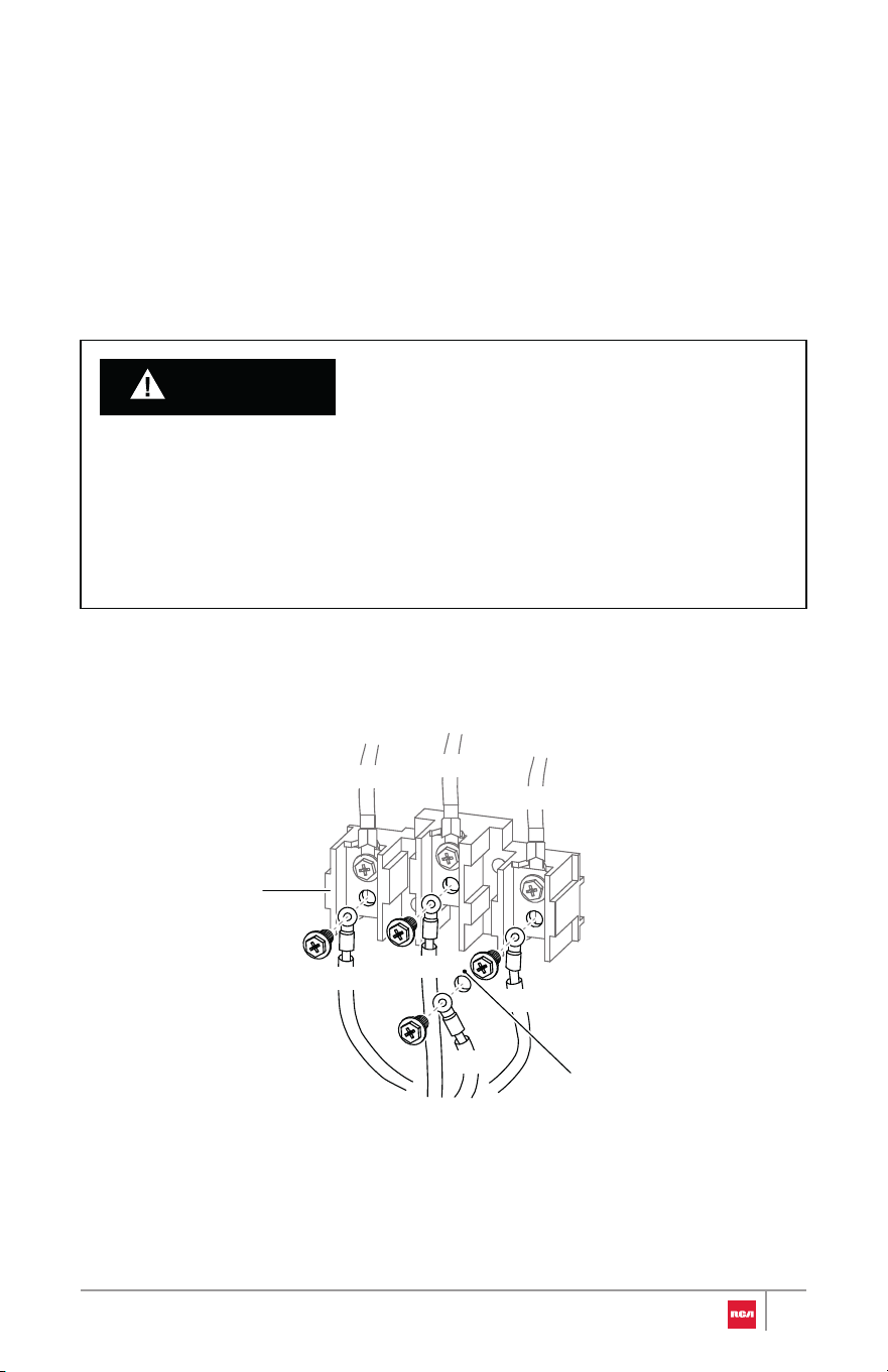
WARNING
4-Wire Connection
Use this method for:
• New branch-circuit installations (1996 NEC)
• Mobile homes
• Recreational vehicles
• Areas where local codes prohibit grounding through the neutral
Power Cord
1. Remove and retain the lower 3 terminal screws from the terminal block.
2. Remove the ground screw. Remove or cut part of metal ground strap.
• The neutral wire of the supply circuit must be connected to the neutral
terminal located in the lower center of the terminal block. The power
leads must be connected to the lower left and the lower right terminals
of the terminal block. The grounding lead must be connected to the
frame of the range with the ground screw. Failure to do so can result in
electrical shock, severe personal injury or death.
RED
WHITE
BLACK
RED
WHITE
BLACK
GREEN
Terminal block
Ground strap
removed
29
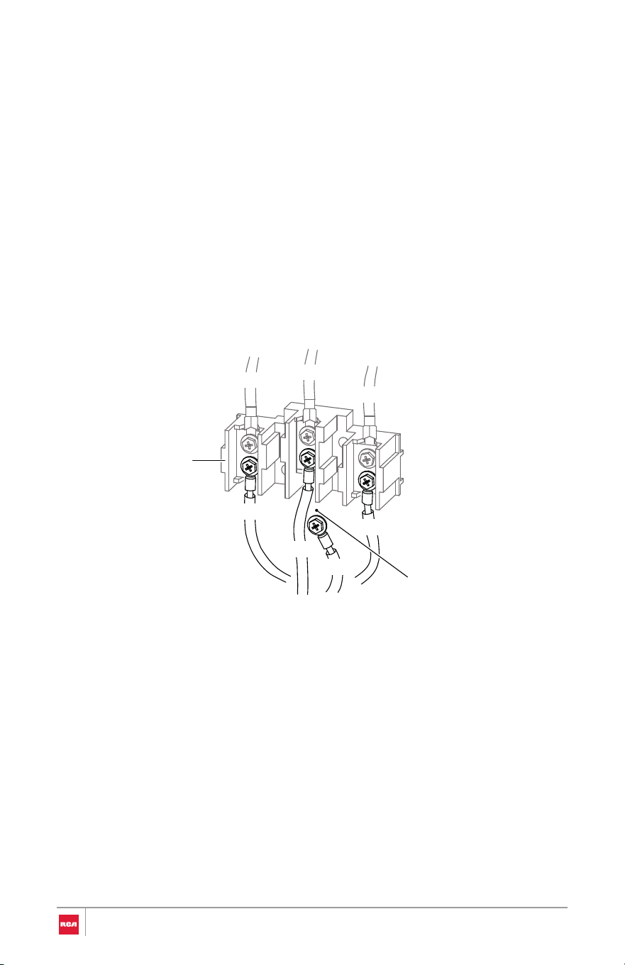
Conduit
3. Insert the ground screw through the power cord ground (green) wire
terminal ring, and secure it to the frame of the range.
4. Insert the 3 terminal screws through each power cord terminal ring an d
into the lower terminals of the terminal block. Make sure that the neutral
(white) wire is connected to the lower center position of the terminal block.
5. Tighten the 3 terminal screws securely into the terminal block, and replac e
the terminal block access cover.
BLACK
RED
WHITE
RED
WHITE
BLACK
GREEN
Terminal block
Ground strap
removed
1. Loosen the lower left and lower right terminal screws from the terminal
block.
2. Remove the lower center terminal screw and the ground screw. Remove o r
cut part of metal ground strap.
3. Attach the bare ground (green) wire end to the range frame and secure i t
in place with the ground screw.
4. Insert the bare neutral (white) wire end into the lower center terminal
block opening.
30
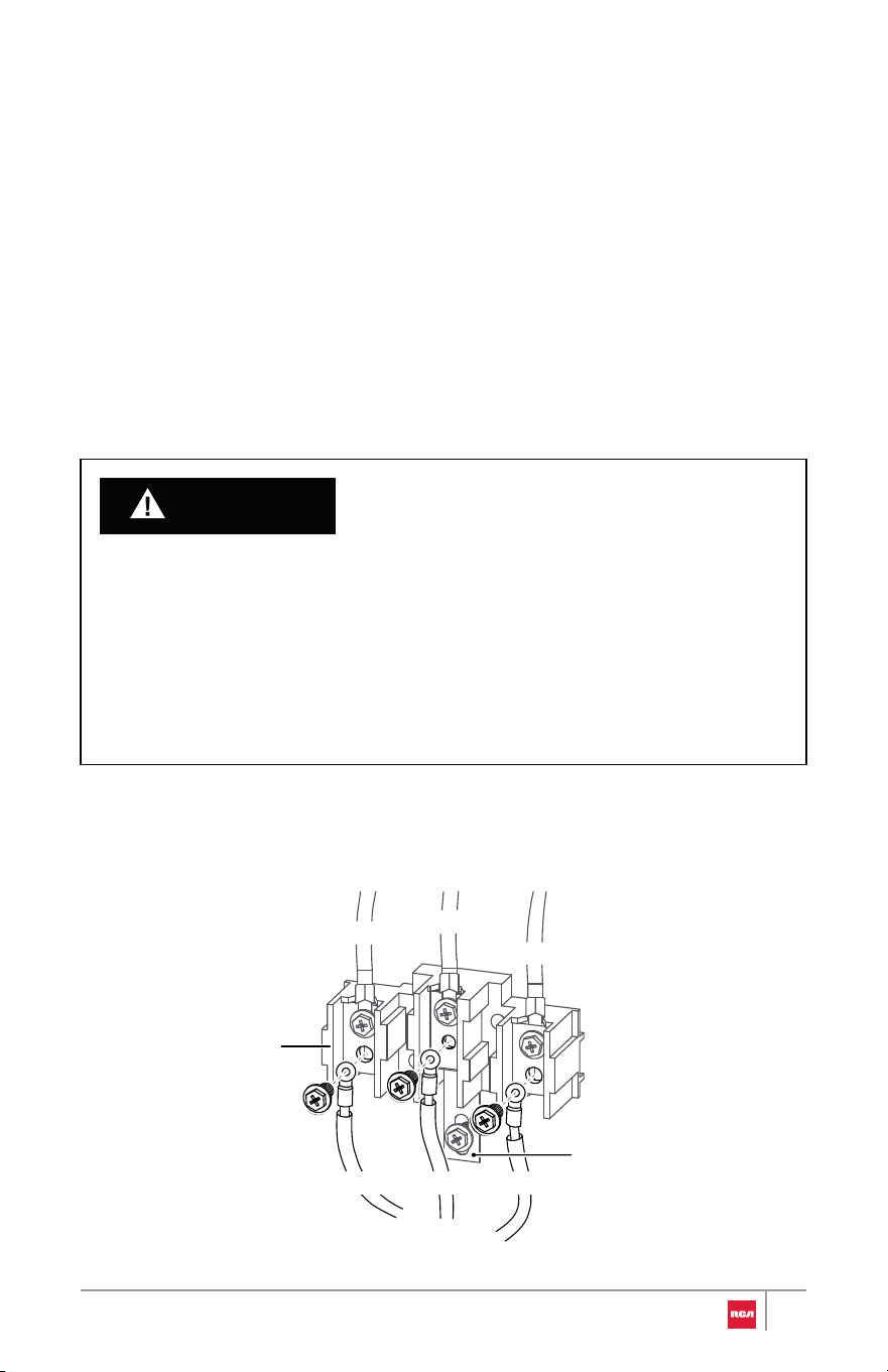
WARNING
5. Insert the two remaining bare wire ends into the lower left and the lower
right terminal block openings.
6. Tighten the 3 terminal screws securely into the terminal block, and replace
the terminal block access cover.
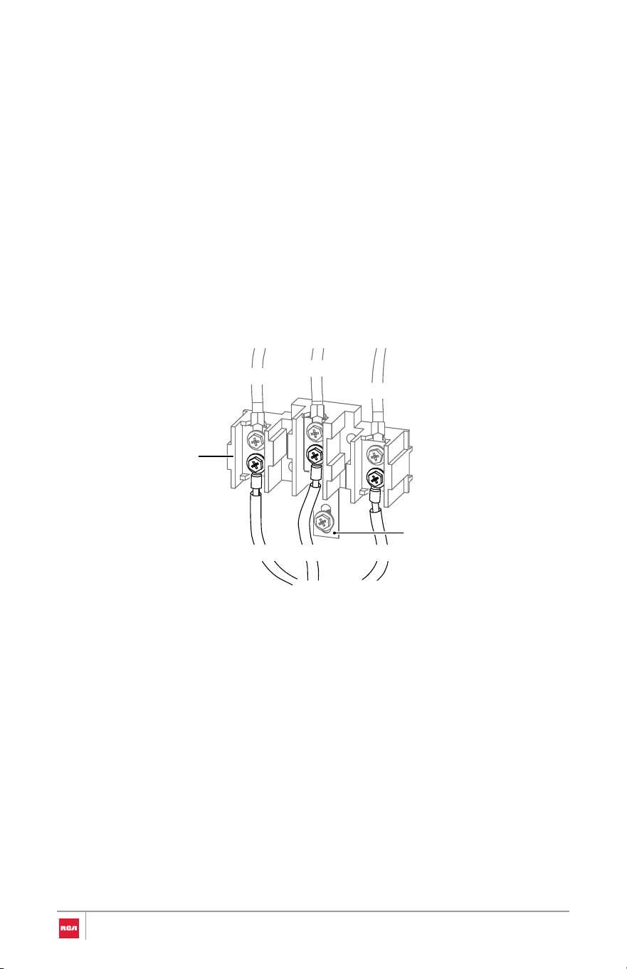
3-Wire Connection
Use this method only if local codes permit connecting chassis ground
conductor to neutral wire of power supply cord.
Power Cord
• The neutral or ground wire of the power cord must be connected to the
neutral terminal located in the lower center of the terminal block and the
ground strap must connect the neutral terminal to the ground plate. The
power leads must be connected to the lower left and the lower right
terminals of the terminal block. Failure to do so can result in electrical
shock, severe personal injury or death.
• Do not remove the ground strap connection.
REDWHITE
BLACK
RED
WHITE
BLACK
Terminal block
Ground strap
31
Conduit
1. Remove and retain the lower 3 terminal screws from the terminal block .
Do not remove the ground strap connection.
2. Insert the 3 terminal screws through each power cord terminal ring an d
into the lower terminals of the terminal block. Make sure that the neutral
(white) wire is connected to the lower center position of the terminal block.
3. Tighten the 3 terminal screws securely into the terminal block, and replac e
the terminal block access cover.
REDWHITE
BLACK
RED
WHITE
BLACK
Terminal block
Ground strap
1. Loosen the lower 3 terminal screws from the terminal block. Do no t
remove the ground strap connection.
2. Insert the bare neutral (white) wire end into the lower center terminal
block opening.
3. Insert the two remaining bare wire ends into the lower left and the lo we r
right terminal block openings.
4. Tighten the 3 terminal screws securely into the terminal block, and replac e
the terminal block access cover.
32
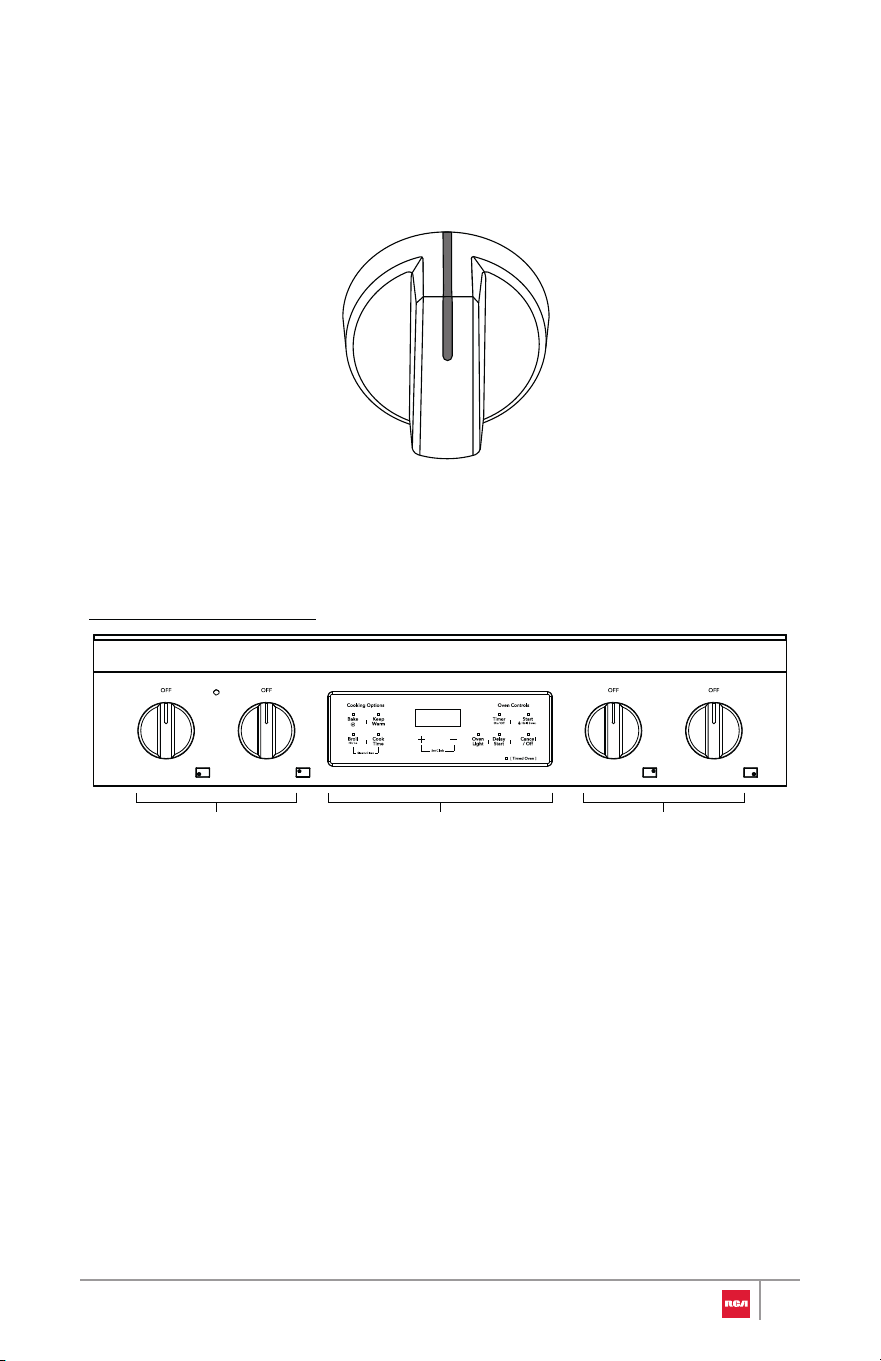
Single element knob
30" Model: R-REH304SS
Install/Remove Control Knobs
Be very careful not to scratch the surface of the unit. The appearance of the
knobs may vary from what are shown below.
H
I
L
O
Surface element
knobs
Surface element
knobs
Oven touch
controls
33
Installing the Control Knob
Removing the Control Knob
1. Pull the knob straight off the stem.
1. Hold the knob in an upright position with the OFF marking facing upward.
Observe the open part centered on the back of the knob.
2. Place and align the open part on the back of the knob over the control
stem that is sticking out of the control panel.
3. Press the knob onto the stem, and make sure the knob is in the OFF
position.
• Hex key (provided)
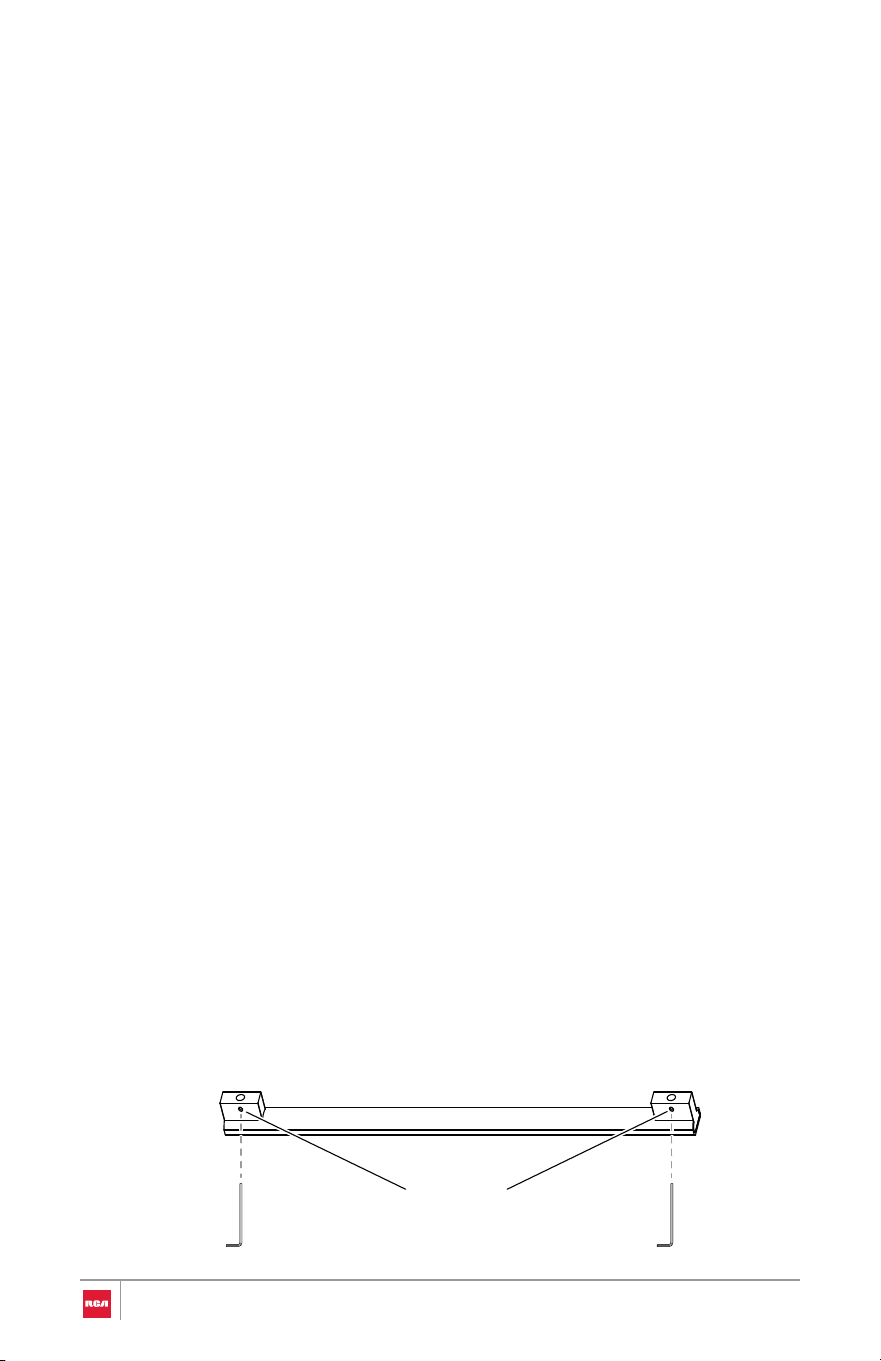
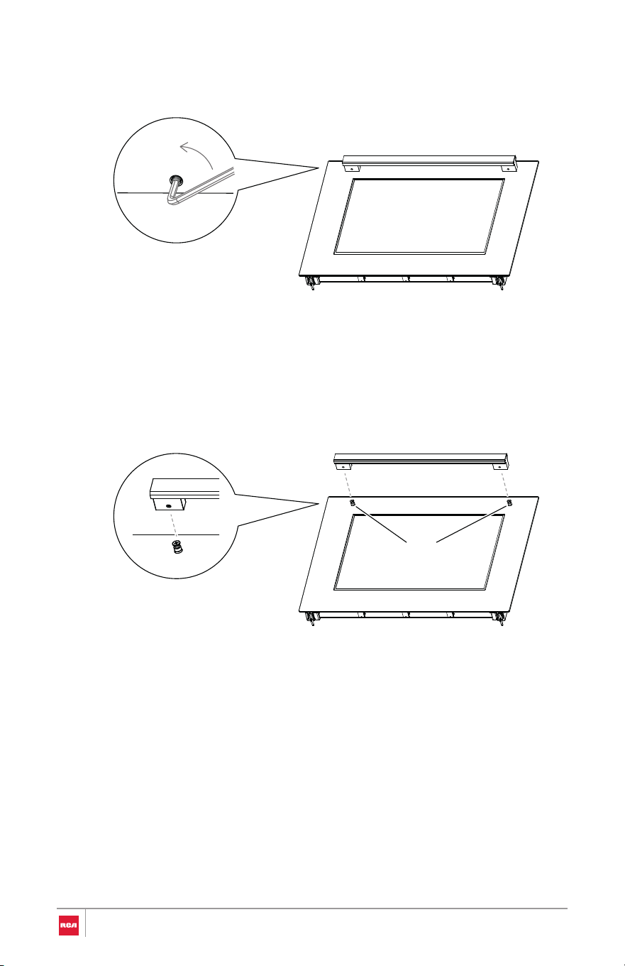
Installing the Handle
1. Partially loosen the set screws in both ends of the handle with the Hex key.
Install/Remove Oven Door Handle
Be very careful not to scratch the surface of the unit. The appearance of the
handle may vary from what is shown below, but the installation will be the
same.
Tool Needed
Set screw
(pre-installed)
34
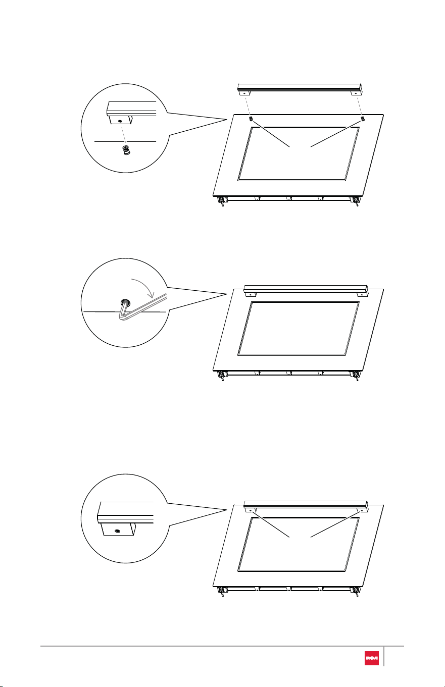
over the mounting fasteners.
2. Place the handle on the door by fitting both ends of the handle footprints
3. Tighten the set screws with the Hex key.
Removing the Handle
1. Locate the set screws for mounting fastener on the handle end caps.
Mounting fastener
Set screw
35
2. Loosen the set screw on one end with the Hex key while supporting the
handle. Do not remove the set screw from the handle end cap.
3. Keep supporting the handle while loosening the set screw on the other
handle end cap.
4. Remove the handle from the mounting fasteners on the door and set
aside.
Mounting fastener
36
Note:
Removing/Assembling Oven Door
For normal range use, it is not suggested to remove the oven door. However, if
removal is necessary, make sure the oven is off and cool.
Removing Door
• The oven door is heavy.
• If door is removed, confirm that door operates correctly and seals
properly when reinstalled. If door gasket does not seal completely, heat
escaping from around doors could ignite cabinetry.
IMPORTANT: Do not lift door by
door handle.
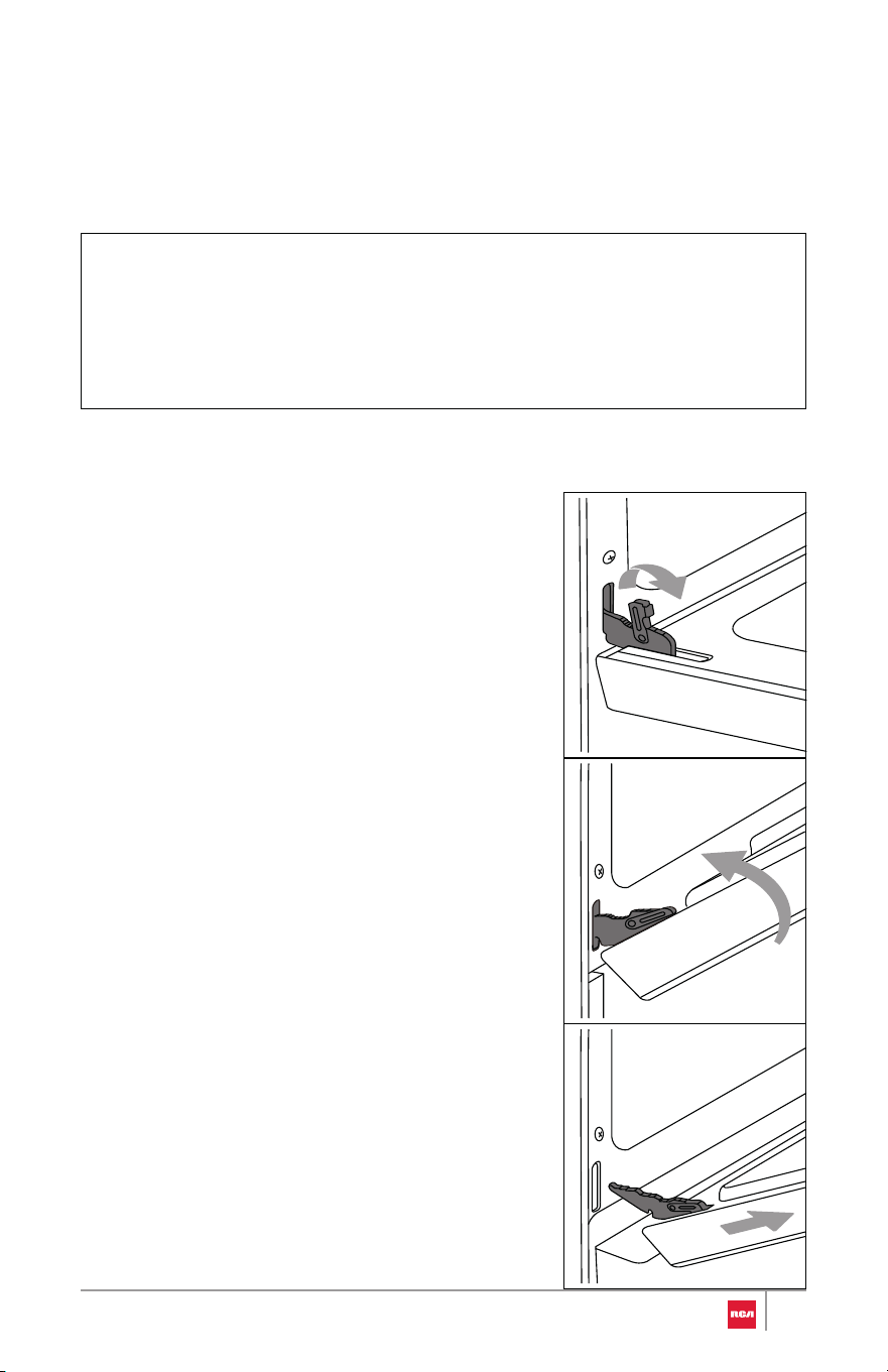
1. Fully open the oven door.
2. Unlock the hinge locks on both
sides, rotating them as far toward
the open door frame as they will
go.
3. Firmly grasp both sides of the
door.
4. Close the door to the removal
position, which is approximately
five degrees or 2-3 inches from
being fully closed. If the position is
correct, the hinge arms will move
freely.
5. Lift door up and out until the hinge
arms are clear of the slots.
37
Assembling Door
IMPORTANT: Do not lift door by
door handle.
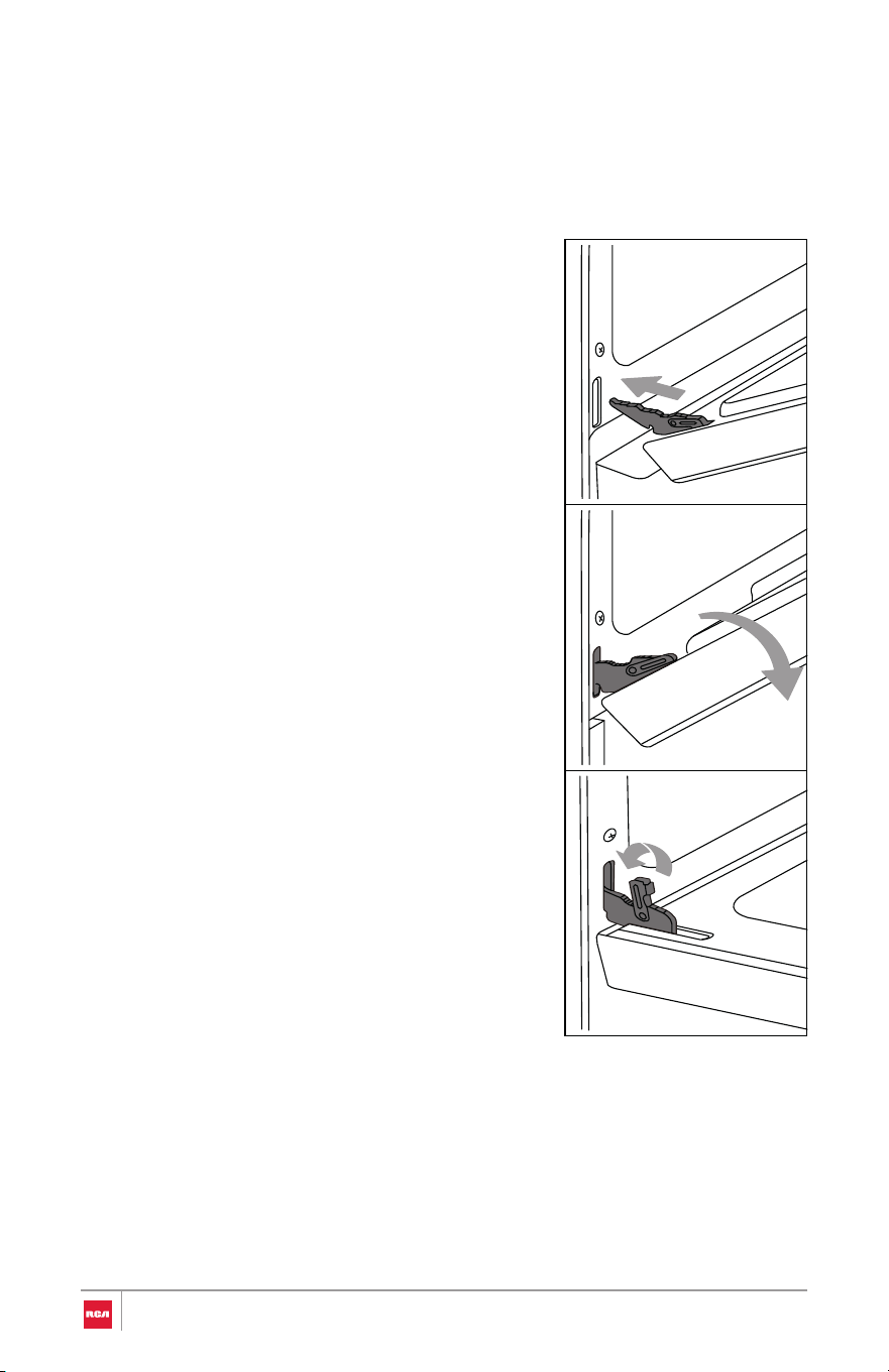
1. Firmly grasp both sides of the
door.
2. With the door at the same angle as
the removal position, which is
approximately five degrees or 2-3
inches from being fully closed,
seat the indentation of the hinge
arms into the bottom edge of the
hinge slots. The notch in the hinge
arms must be fully seated into the
bottom edge of the slots.
3. Open the door fully. If the door will
not open fully, the indentation is
not seated correctly in the bottom
edge of the slots.
4. Lock the hinge locks, rotating
them back toward the slots in the
oven frame until they lock.
5. Close the oven door. Check that
the door is free to open and close
and is level while closed.
38

Removing/Assembling Storage Drawer
For normal range use, it is not suggested to remove the storage drawer. Most
cleaning can be done with the drawer in place. However, if removal is
necessary, make sure the drawer is empty.
Removing Drawer
1. Fully open the drawer.
2. Carefully lift the front end of the drawer and pull the drawer away from the
range.
Assembling Drawer
1. Tilt the front end of the drawer up.
2. Align and insert the rear wheel on each side of the drawer onto the glides
on the range.
3. Carefully lower the front end of the drawer and push the drawer into the
range.
4. Open and close the drawer to ensure it is properly installed.
39
WARNING
Electrical Shock Hazard
• Remove house fuse or open circuit breaker to disconnect power befo re
servicing.
• Plug into a grounded outlet.
• Do not use an adapter or an extension cord.
• Failure to do so can result in death, fire, or electrical shock.
Complete Installation
Placement and Leveling Range
WARNING
Excessive Weight Hazard
CAUTION
Laceration, Foreign Object, Crush Hazard
• Use two or more people to move and install oven. Failure to do so can
result in back or other injury.
• When installing, moving, or servicing any appliance, wear proper
protective equipment, including cut resistant gloves, steel-toed shoes,
and safety glasses.
40

IMPORTANT:
• Do not lift by the oven door handle or control knobs. Push, pull, or lift only
on the body or structural areas, such as oven, oven face, or back corners of
range.
• Do not move unit by pushing or pulling on the door or control panel.
Grasp the left/right door area to push the unit.
• Move range by lifting, not sliding, to prevent damage to floors.
• Use a belt when moving the range to prevent damaging the floor, or use
cardboard, plywood, or stiff plastic to protect floors if sliding is necessary.
• Be careful not to pinch or kink the electrical connection. If unit does not
move in smoothly, check for obstructions. Do not attempt to force the unit
into position.
Getting the unit properly placed in the installation space and level may require
multiple attempts. It is recommended to measure and adjust leveling legs
carefully before placing into the installation space, as the leveling legs may be
difficult to adjust once the range is in its final position.
1. Measure the distance from the top of the countertop to the floor at all four
corners of the installation space.
2. While range is still positioned outside the installation space, measure the
distance from the top of the cooktop to the bottom of each leveling leg.
• If this distance does not match the distance measured at the
corresponding corner of the installation space, use a wrench or pliers
to loosen and adjust the leveling legs to the correct height.
Note:
• Height adjustment can be made when range is standing. Tilt the
range back to adjust the front legs, and then tilt forward to adjust
the rear legs.
• The leveling legs can be loosened up to a maximum of 1" (2.6 cm).
3. When the range is at the correct height, check and make sure that there is
minimum clearance of 11/16" (1.8 cm) under the range for the anti-tip
bracket.
41
4. Check that all range controls are in the OFF position. Plug power cord into
a grounded outlet or connect conduit to a grounded junction box.
5. Using 2 or more people, gently move range into its final location and
make sure the rear leveling leg is engaged in the slot of the anti-tip
bracket.
Note:
• Be careful not to damage countertops, floor, or appliance when
moving.
• Check to ensure the electrical cord is not pinched or kinked.
6. Place level diagonally on the oven bottom or oven rack, and check with
the level in each diagonal direction. Adjust the leveling legs as necessary.
• If range is not level, use a wrench or pliers to adjust leveling legs up or
down until the range is level.
Note:
• The range must be level for optimum cooking and baking
performance.
7. Reassemble oven door and storage drawer and insert oven racks if they
were previously removed. See "Removing/Assembling Oven Door" and
"Removing/Assembling Storage Drawer" sections.
Verify Anti-Tip Bracket Engagement
Do not operate the range without anti-tip bracket installed and engaged.
IMPORTANT: If the range is moved from the final location for any reason,
always verify anti-tip bracket engagement again.
42
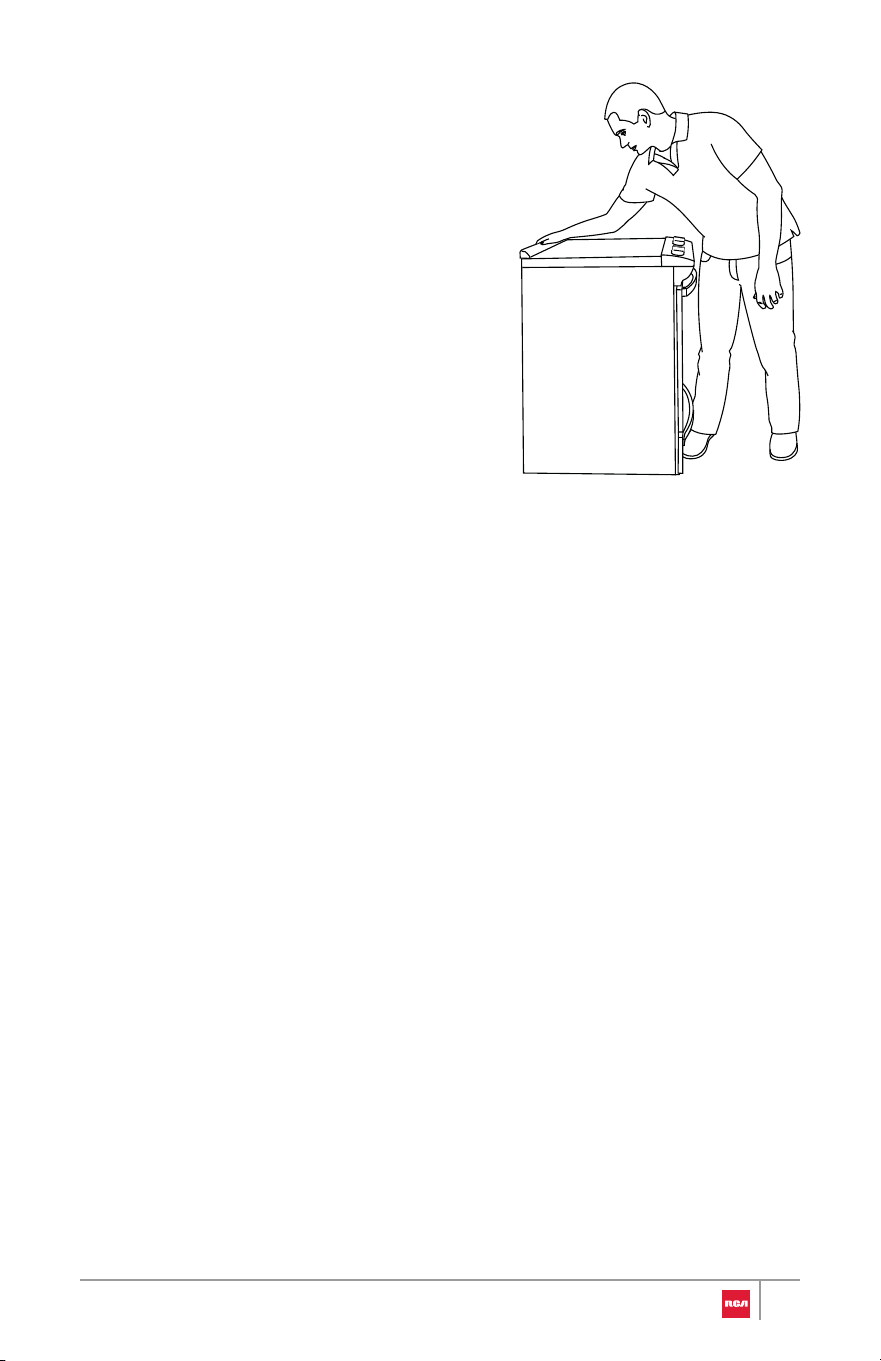
1. Place the outside of your foot agains t
the bottom of the front panel to k eep
the range from moving, and then gras p
the back of the range as shown.
2. Carefully and slowly attempt to tilt th e
range forward.
• If you encounter immedia te
resistance, the rear foot is
engaged in the anti-tip bracket .
Verification is completed. Skip th e
steps below.
• If the rear of the range lifts more
than 1/2" (1.3 cm) off the floo r
without resistance, stop tilting th e
range and lower it gently back t o
the floor. The rear range foot is no t
engaged in the anti-tip bracke t.
Proceed to Steps 3 and 4.
IMPORTANT: If there is a snapping or popping sound when tilting the
range, the range may not be fully engaged in the anti-tip bracket. Check
to see if there are obstructions keeping the range from sliding to the wall
or keeping the rear range foot from sliding into the bracket. Verify that the
bracket is held securely in place by the mounting screws.
3. Slide the range forward, and verify that the anti-tip bracket is securel y
attached to the floor or wall.
4. Slide range back so the rear range foot is inserted into the slot of the anti-
tip bracket.
5. Repeat steps 1 and 2 to ensure that the rear range foot is engaged in th e
anti-tip bracket.
• If the rear of the range lifts more than 1/2" (1.3 cm) off the floo r
without resistance, the anti-tip bracket may not be installed correctly .
Please reference the contact information at the end of this manual to
contact service.
43
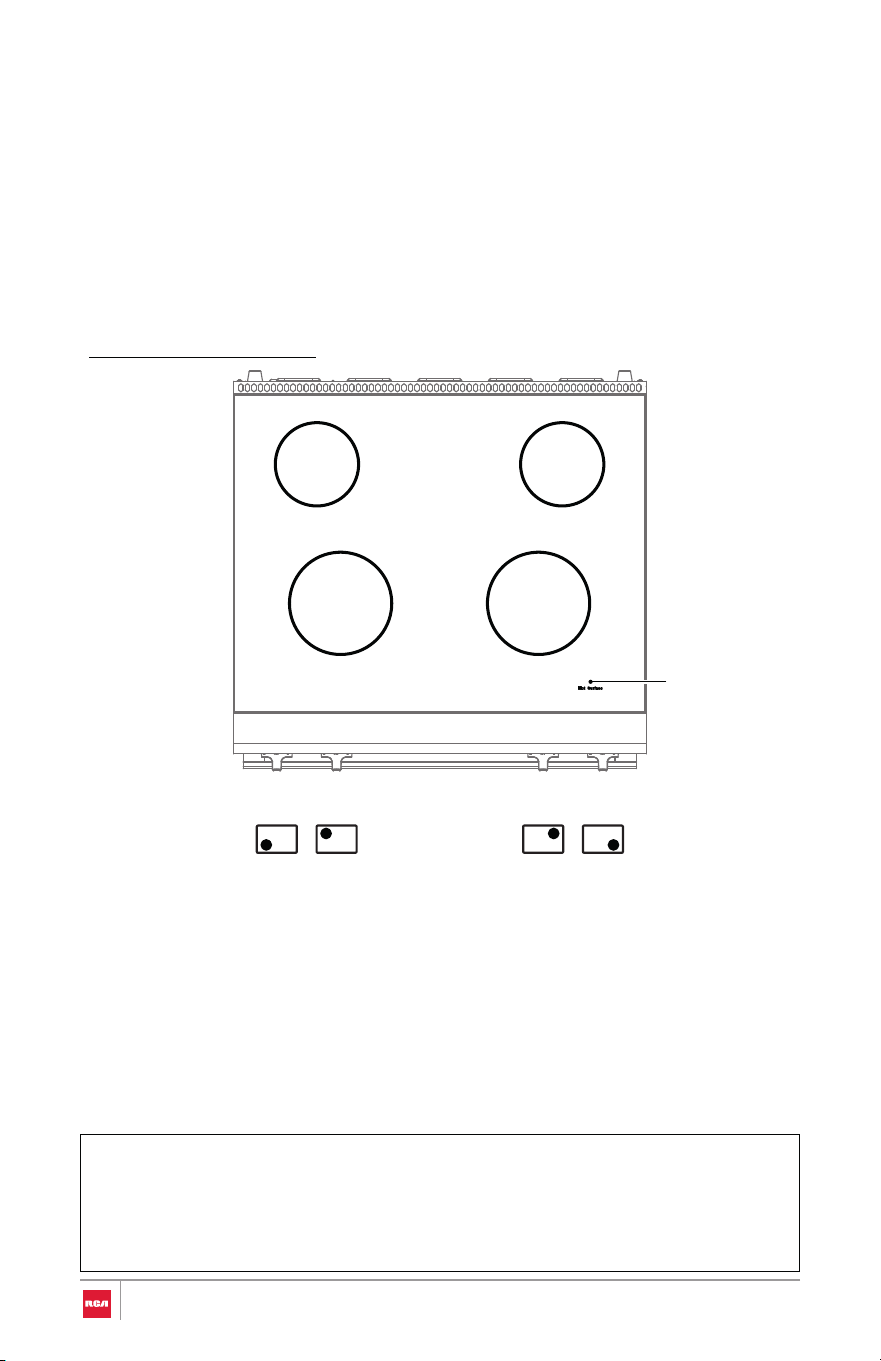
Checking Operation of the Surface Heating Elements
IMPORTANT:
30" Model: R-REH304SS
Standard Surface Heating Elements
• Check that all packing material and tape have been removed. Failure to
remove these materials could result in damage to the appliance once the
appliance has been turned on and surfaces have heated.
• Be sure power is in service.
Note:
• Turn each knob to the "Hi" position to check that the surface heating
elements are working properly.
The elements should glow red and radiate heat, and they should cycle on
and off periodically even when the knob is in the "Hi" position.
• The hot surface indicator light on the surface glows and indicates that
cooktop element is still hot. When the hot surface indicator turns off, the
glass surface may still feel slightly hot to touch.
2100 W 2100 W
1200 W 1200 W
Hot surface
indicator light
44
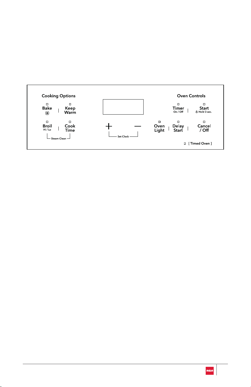
Check Operation of the Oven
IMPORTANT:
To Check Broil Heating Element:
• Ensure all packaging is removed, and oven is empty except for oven
rack(s).
• Be sure power is in service.
1. Keep the oven door closed.
2. Press Broil once to select High Broil mode.
3. Press Start.
The oven starts to preheat, and HI remains in the display.
4. After several minutes, the upper broil heating element can be visually seen
to start glowing red.
• If you do not see heating element glowing red, open the oven door
temporarily. Without touching the oven components, confirm that
heat can be felt radiating from the oven top.
• If you do not feel heat, turn off the oven and contact a qualified
technician.
5. Press Cancel/Off to stop High Broil mode.
45
To Check Bake Heating Element:
Note:
1. Kee
p the oven door closed.
2. Press Bake twice to select Convection Bake mode.
The indicator light above Bake flashes.
3. Press Start to select the default temperature.
--:-- appears in the display, prompting for cooking time to be entered.
4. Press Start to skip setting the cook time.
The oven starts to preheat, and PRE appears in the display.
5. After a couple minutes, open the oven door temporarily. Without touchin g
the oven components, confirm that heat can be felt radiating from th e
oven bottom and the rear convection fan is operating.
• If you do not feel heat, turn off the oven and contact a qualifie d
technician.
• If the door is left open too long for over 3 minutes, the cookin g
mode will be automatically cancelled.
6. Close the oven door. Let the oven run for 10 minutes.
• (Optional) After preheating is complete, allow oven to run for at leas t
30 minutes to burn off and remove any manufacturing protection oil ,
dust or impurities.
7. Press Cancel/Off to stop Convection Bake mode.
46
IMPORTANT
Do Not Return This Product to The Store
If you have a problem with this product, please contact Customer Support at
+1 (626) 800-4288
Dated proof of purchase, model #, and serial # required for warranty service.
IMPORTANT
Ne pas Réexpédier ce Produit au Magasin
Pour tout problème concernant ce produit, veuillez contacter le service de s
consommateurs Customer Support au
+1 (626) 800-4288
Une preuve d’achat datee est requise pour beneficier de la garantie.
IMPORTANTE
No regrese este producto a la tienda
Si tiene algún problema con este producto, por favor contacte el ayuda al
cliente al
+1 (626) 800-4288
(Válido solo en E.U.A.)
Necesita una prueba de de compra fechada, número de modelo y de serie
para el servicio de la garantía.
Correct disposal of this product:
This marking indicates that this appliance should not be
disposed with other household wastes. To prevent
possible harm to the environment or human health from
uncontrolled waste disposal, recycle it responsibly to
promote the sustainable reuse of material resources.
47

For service assistance and product
information please call:
1-626-800-4288
Electronic version of this manual is
available at:
www.fgsbrands.com/rca-manuals
This product has been manufactured and sold under the responsibility of
Future Global Supply, LLC.
RCA, the RCA logo and the two dogs (Nipper and Chipper) logo are
trademarks used under license by Future Global Supply, LLC – further
information at www.rca-brand.com.
All other products, services, companies, trademarks, trade or product names
and logos referenced herein are the property of their respective owners.