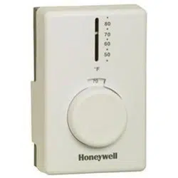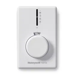
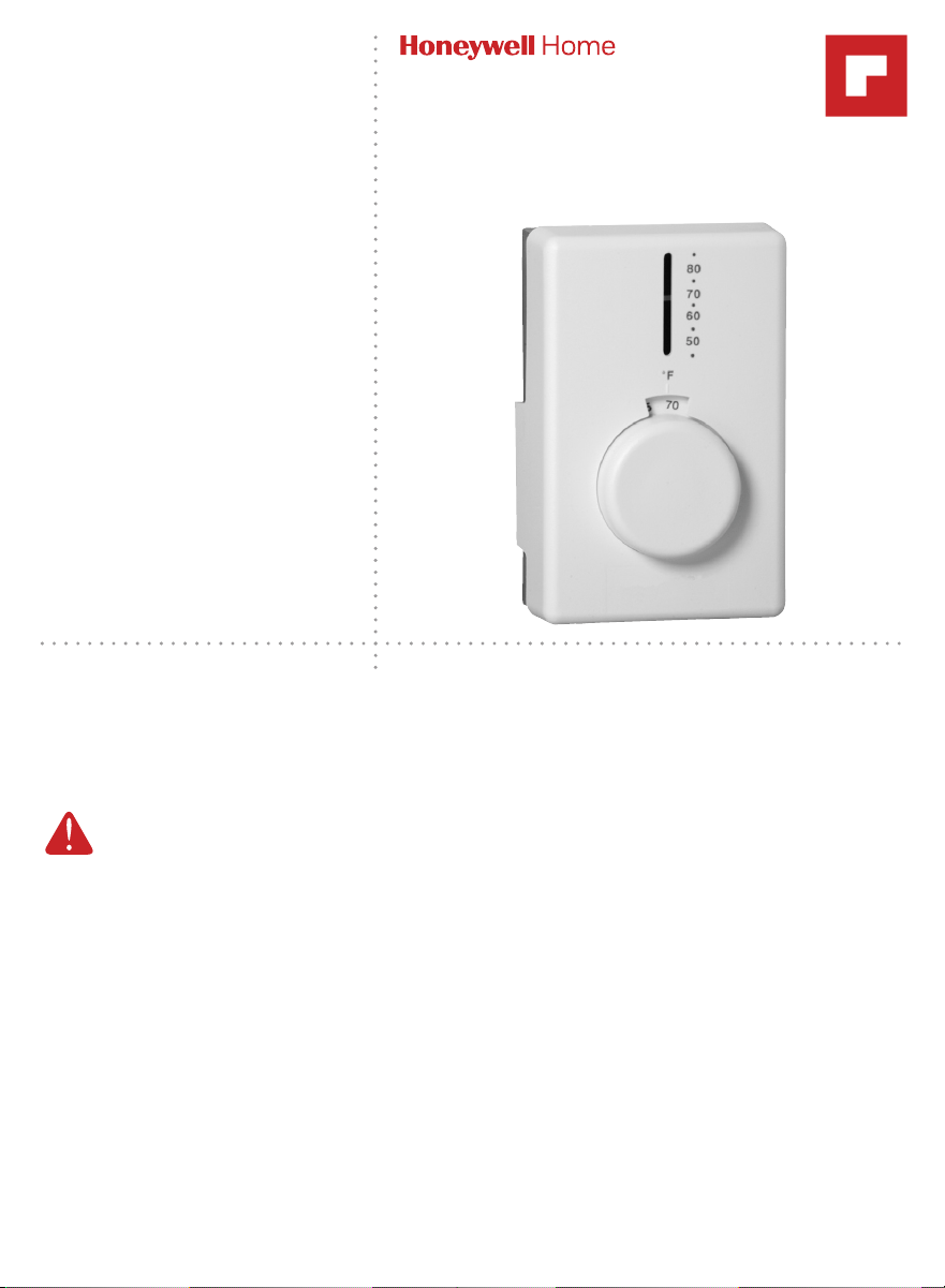
Owner’s Manual
Read and save these
instructions.
For help please visit
honeywellhome.com
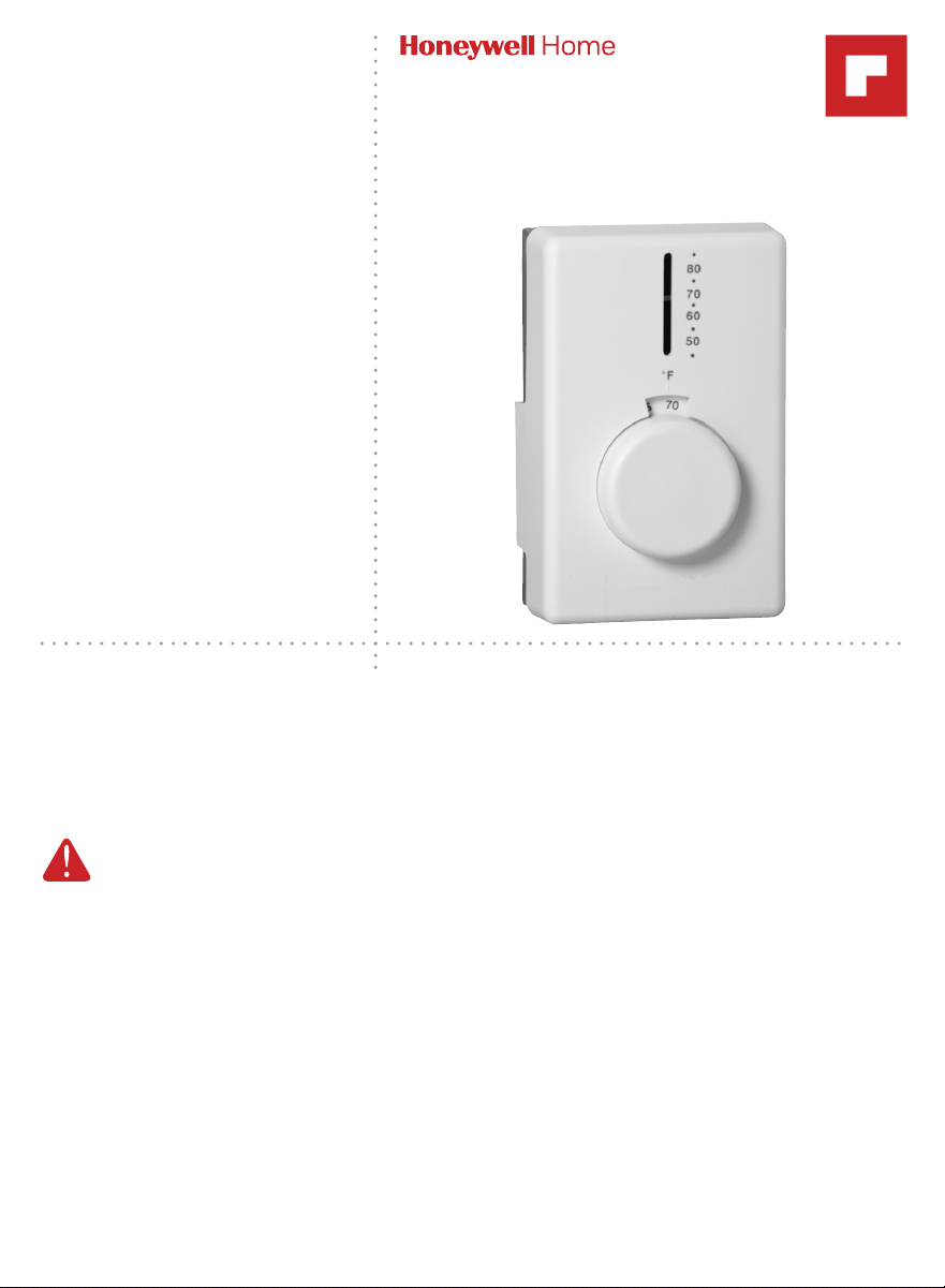
CT62A, B
Line Voltage
Electric Heat
Thermostat
Application
Your new CT62 Electric Heating Thermostat provides line voltage control of a radiant
cable, electric baseboard, and resistive-rated fan forced heaters within the ratings
listed below.
WARNING Electrical Shock Hazard.
This thermostat is a line voltage control (120–240 Volts). Do not install it if you
are not completely familiar with house wiring. If handled improperly, there is
risk of electric shock hazard, which may cause serious injury or death.
Specifications
• CT62A provides single-line break.
• CT62B provides double-line break.
Temperature Range: 50°F to 80°F (10°C to 25°C)
Electrical Ratings: 60 Hz noninductive; 22A at 120-240 Vac; 19A at 277 Vac

2
ATTENTION: MERCURY RECYCLING NOTICE
This product does not contain mercury.
However, this product may replace a product
that contains mercury. Mercury and products
containing mercury should not be discarded in
household trash.
For more information on how and where to
properly recycle a thermostat containing
mercury in the United States, please refer to the
Thermostat Recycling Corporation at
www.thermostat-recycle.org.
For mercury thermostat recycling in Canada,
please refer to Switch the Stat at
www.switchthestat.ca
NO MERCURY
Hg
Installation
When Installing This Product
1. Read these instructions carefully. Failure to follow them could damage the
product or cause a hazardous condition.
2. Check the ratings given in these instructions to make sure the thermostat
is suitable for your application.
3. After installation is complete, check out operation as provided in these
instructions.
Preparation
• Proper installation of your thermostat will occur if you follow these
instructions STEP-BY-STEP. It is recommended that as you read,
understand and complete each step, you check it off with pencil or pen.
• Check thermostat suitability for your home’s system by reviewing the
ratings listed above.
• Make certain that your heating system is working, especially if it has been
inoperative for a length of time. If the system does not work, contact your
local electrician for assistance.
• Carefully unpack your new thermostat. To avoid damage to the sensing
element, do NOT remove the thermostat cover until wiring has been
completed.
• Save packages of screws, instructions, receipt and proof-of-purchase.
3
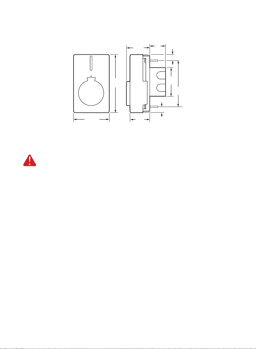
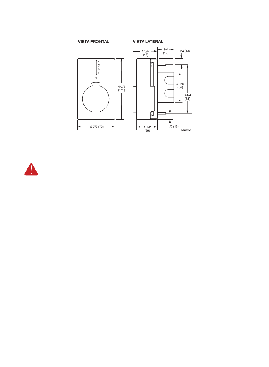
Thermostat Mounting Dimensions
M5795B
FRONT VIEW SIDE VIEW
80
•
70
•
60
•
50
•
˚F
4-3/8
(111)
2-7/8 (73)
1-1/2
(39)
1-3/4
(48)
1
(25)
1/2 (13)
1/2 (13)
2-1/8
(54)
3-1/4
(83)
Remove Old Thermostat
WARNING Electrical Shock Hazard. Can cause severe injury, death
or property damage.
Begin by turning off power to the heating circuit at the main service
panel.
1. Remove cover of old thermostat—cover normally snaps off when pulled
firmly from the bottom. If it resists, check for a screw that locks the cover.
2. Loosen screws holding thermostat base to outlet box and lift away.
3. Disconnect wires from old thermostat. As you disconnect each wire, tape
the end and label it with the letter of the terminal designation to make
reconnection to new thermostat easier.
4. Check the old insulation for cracks, nicks or fraying, and apply high quality
plastic tape where necessary for adequate insulation.
5. Retain the old thermostat for reference purposes and until your new
thermostat is functioning smoothly.
4
Wire and Mount New Thermostat
1. Turn the temperature setting
knob to 65°F (18°C). This will
prevent accidental damage to the
knob stop during mounting.
2. Remove thermostat cover by
grasping the top and bottom
ends with fingers, and pulling
outward.
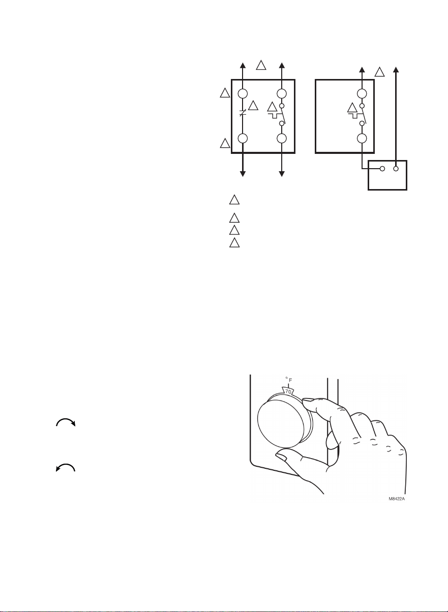
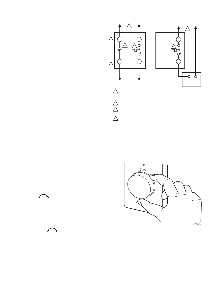
3. Connect wires to the thermostat
as shown in the applicable
wiring diagram. Push the wires
into the outlet box, and insert
the thermostat into the box for
mounting by pushing against top
and bottom of the thermostat
base.
IMPORTANT
Do not press on setting knob. Rough
handling or strong pressure can
damage knob or sensing element,
and change calibration.
4. Secure the thermostat to the box with the two captive mounting screws
provided.
5. Replace thermostat cover.
6. Set knob to desired room temperature.
Check Out Thermostat
1. Turn on the power to the heating
system.
2. Turn setting knob all the way clockwise
; listen for clicking sound as switch
makes contact. Electric heater should
begin operation.
3. Turn knob all the way counterclockwise
; listen for clicking sound as switch
breaks contact. Electric heater should
shut off.
Setting Thermostat
1. Begin with setting knob at 70°F (20°C) on the scale.
2. If this setting is not satisfactory after at least two hours of operation,
turn setting knob up to raise the temperature, or down to lower the
temperature. Move knob only a degree each time.
L1
(HOT)
L2
1
1
1
2
3
4
3
2
4
4
POWER SUPPLY. PROVIDE DISCONNECT MEANS AND OVERLOAD
PROTECTION AS REQUIRED.
BREAKS ON POSITIVE OFF.
EXPOSED UNUSED LEADWIRES TO BE PROPERLY INSULATED.
THERMALLY ACTIVATED—BREAKS ON TEMPERATURE
RISE. MAKES ON TEMPERATURE FALL.
L2
L1
L1
T2
T1
T1
CT62ACT62B
3
ELECTRIC
HEATER
CAUTION:
SPECIAL SERVICE CO/ALR SOLDERLESS CONNECTORS MUST
BE USED WHEN CONNECTING WITH ALUMINUM CONDUCTORS;
OTHERWISE, A FIRE HAZARD CAN RESULT.
TO
ELECTRIC
HEATER
M8420A
5
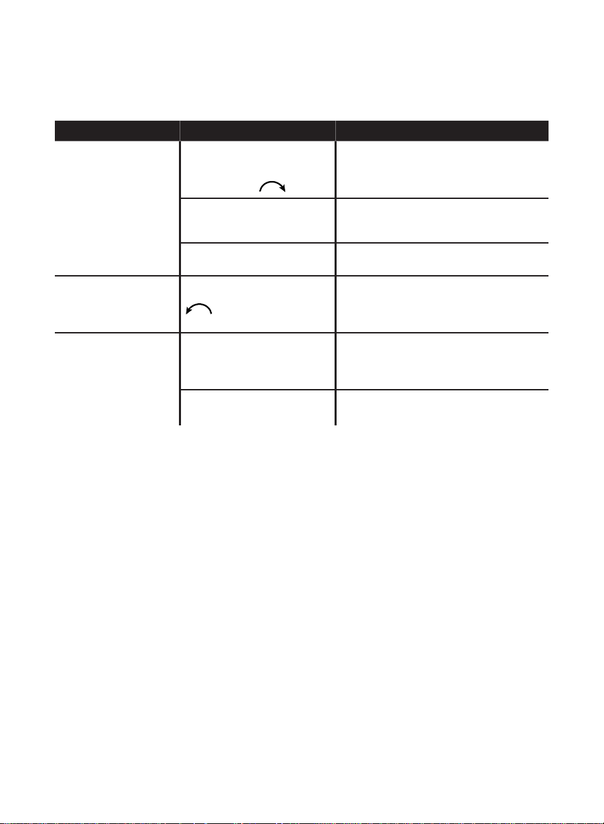
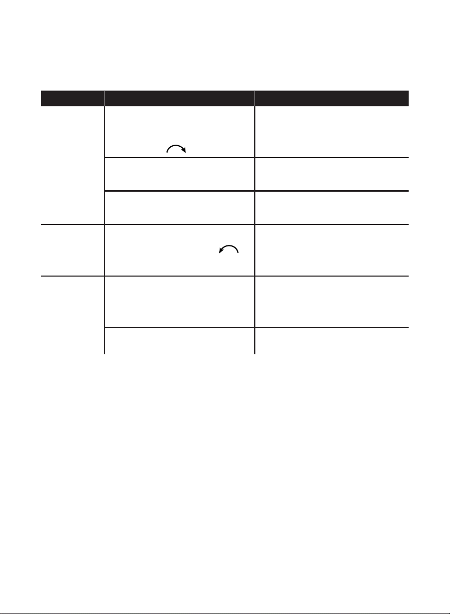
Troubleshooting
Your thermostat requires little or no attention. Most problems can generally
be traced to the following:
Symptom Checkout Action
No heat. Make sure power is on at
main service panel. Turn the
temperature setting knob
fully clockwise
.
Heater should start to warm up within
two minutes. If not, contact qualified
electrician to check thermostat and
heater.
Improper connections to
thermostat.
With power to circuit OFF, tighten all
wiring connections. Repair any frayed or
broken wires.
Other. Contact a qualified electrician for
assistance.
Heater never turns off. Turn temperature setting
knob fully counterclockwise
.
Heater should start to cool within
minutes. If not, turn off power at
the main service panel, and contact
qualified electrician.
Thermostat setting
and thermometer
reading disagree.
Thermostat affected by
drafts or radiant heat.
Contact electrician to change the
location. The thermostat should be
about 5 ft (1.5m) above the floor and on
an inside wall.
Thermometer is out of
calibration.
Recalibrate. See “Recalibration
Procedure” on page 6.
Calibration
The CT62 Thermostats are calibrated at the factory using precise instruments
under closely controlled conditions. Recalibration should not be necessary.
Allow the thermostat to operate for several hours before checking the
calibration. The CT62 Thermostat vapor-filled dual diaphragm sensing
element is affected by barometric pressure and altitude. Temperature
deviations of 1°F (0.5°C) are normal. If the thermostat is mounted in a
suitable location and still appears out of calibration, check calibration as
follows:
Check Calibration
1. Turn the setting knob clockwise until the switch makes (clicking sound).
The heating equipment and fan start.
2. No recalibration is necessary if the thermostat switch makes with
the thermostat setting at the same temperature as indicated on the
thermometer.
3. If the thermostat setting differs from the thermometer, record the
temperature difference and recalibrate as instructed in the Recalibration
Procedure section.
33-00143ES-03
Resideo Inc., 1985 Douglas Drive North
Golden Valley, MN 55422
www.resideo.com
This product is manufactured by Resideo Technologies, Inc.,
Golden Valley, MN, 1-800-468-1502
© 2019 Resideo Technologies, Inc. The Honeywell Home trade-
mark is used under license from Honeywell International Inc.
All rights reserved.
33-00143ES—03 M.S. Rev. 06-19 | Printed in United States
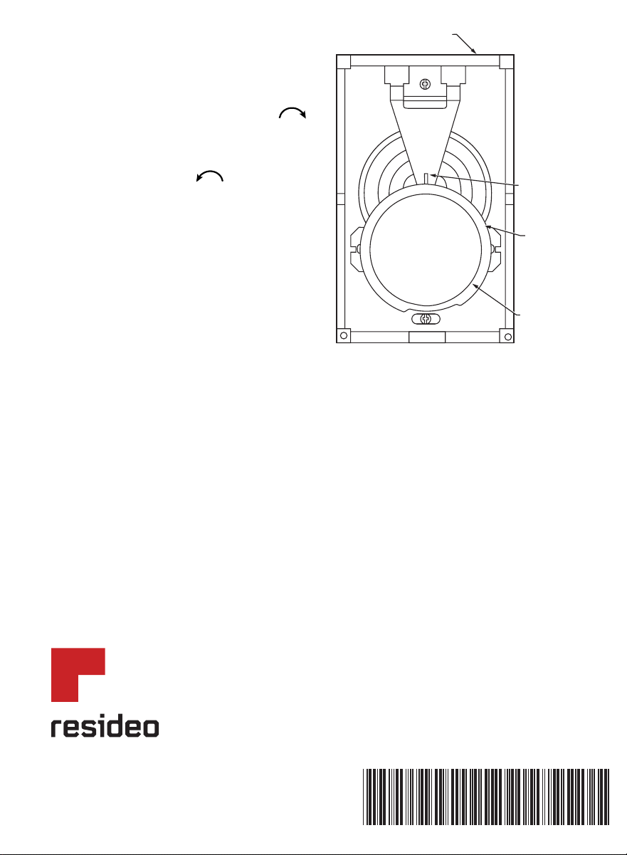
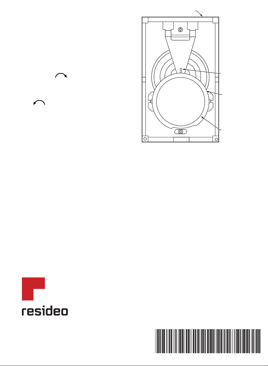
Recalibration Procedure
1. Note the temperature difference
between the temperature setting and
the thermometer.
2. Remove the thermostat cover.
3. Rotate setting knob clockwise
until you hear switch click.
4. Hold the setting knob firmly and
rotate the set point scale ring
counterclockwise
until the 12
o’clock position of the ring agrees
with the cover thermometer.
5. The heat from your hand will affect
the diaphragm sensor. Replace
thermostat cover, wait five minutes
and recheck calibration.
1-year limited warranty
Resideo warrants this product, excluding battery, to be free
from defects in workmanship or materials, under normal use
and service, for a period of one (1) year from the date of first
purchase by the original purchaser. If at any time during the
warranty period the product is determined to be defective due
to workmanship or materials, Resideo shall repair or replace it (at Resideo’s option).
If the product is defective,
(i) return it, with a bill of sale or other dated proof of purchase, to the place from which you purchased it; or
(ii) call Resideo Customer Care at 1-800-468-1502. Customer Care will make the determination whether the product
should be returned to the following address: Resideo Return Goods, 1985 Douglas Dr. N., Golden Valley, MN 55422,
or whether a replacement product can be sent to you.
This warranty does not cover removal or reinstallation costs. This warranty shall not apply if it is shown by Resideo
that the defect was caused by damage which occurred while the product was in the possession of a consumer.
Resideo’s sole responsibility shall be to repair or replace the product within the terms stated above. RESIDEO SHALL
NOT BE LIABLE FOR ANY LOSS OR DAMAGE OF ANY KIND, INCLUDING ANY INCIDENTAL OR CONSEQUENTIAL
DAMAGES RESULTING, DIRECTLY OR INDIRECTLY, FROM ANY BREACH OF ANY WARRANTY, EXPRESS OR
IMPLIED, OR ANY OTHER FAILURE OF THIS PRODUCT.
Some states do not allow the exclusion or limitation of incidental or consequential damages, so this limitation may
not apply to you.
THIS WARRANTY IS THE ONLY EXPRESS WARRANTY RESIDEO MAKES ON THIS PRODUCT. THE DURATION OF ANY
IMPLIED WARRANTIES, INCLUDING THE WARRANTIES OF MERCHANTABILITY AND FITNESS FOR A PARTICULAR
PURPOSE, IS HEREBY LIMITED TO THE ONE YEAR DURATION OF THIS WARRANTY. Some states do not allow
limitations on how long an implied warranty lasts, so the above limitation may not apply to you.
This warranty gives you specific legal rights, and you may have other rights which vary from state to state. If you have
any questions concerning this warranty, please write Resideo Customer Care, 1985 Douglas Dr, Golden Valley, MN
55422 or call 1-800-468-1502.
M5796A
THERMOSTAT
BASE
SETTING KNOB
AT 12 O'CLOCK
POSITION
SETTING KNOB
SCALE RING
8
0
7
5
7
0
6
5
6
0
5
5
5
0
CT62A, B
Lea y guarde estas
instrucciones.
Para obtener ayuda, visite
honeywellhome.com
Manual del
propietario
Termostatos
de voltaje de
línea, para
calefacción
eléctrica
Aplicación
Su nuevo Termostato para calefacción eléctrica CT62 proporciona control de tensión
de línea para calentadores de cable radiante, calefacción por zócalo eléctrico y
calentadores de tipo resistivos accionados por ventilador dentro de los valores
nominales enumerados anteriormente.
ADVERTENCIA Riesgo de descarga eléctrica.
Este termostato es un control de tensión de línea (120/240 V). No lo instale si
no conoce bien el cableado de su hogar. La manipulación incorrecta de este
termostato puede causar riesgos de descargas eléctricas, y esto puede causar
lesiones graves o la muerte.
Especificaciones
• CT62A proporciona cambio de línea simple.
• CT62A proporciona cambio de línea doble.
Rango de temperatura: de 50 °F a 80 °F (de 10 °C a 25 °C)
Rangos eléctricos: 60 Hz no inductivo; 22 A a 120/240 V CA; 19 A a 277 V CA

2
Instalación
Cuando instale este producto
1. Lea estas instrucciones atentamente. Si no las sigue, puede dañar el
producto o causar una situación de riesgo.
2. Revise los rangos especificados en estas instrucciones para asegurarse de
que el termostato es adecuado para la aplicación correspondiente.
3. Después de que haya finalizado la instalación, revise el funcionamiento
del artefacto según lo especificado en estas instrucciones
Preparación
• La instalación de su termostato resultará exitosa siempre y cuando siga
estas instrucciones PASO POR PASO: Se recomienda que, a medida que
vaya leyendo, comprendiendo y cumpliendo con cada uno de los pasos
mencionados, los vaya marcando con una tilde utilizando una lapicera o
lápiz.
• Revise los valores nominales enumerados anteriormente para verificar que
el termostato sea adecuado para su uso en su hogar.
• Asegúrese de que su sistema de calefacción funcione adecuadamente,
especialmente si el mismo no se ha utilizado durante un período de tiempo
prolongado. Si el sistema no funciona, comuníquese con su electricista
local para recibir ayuda.
• Desembale el termostato nuevo con cuidado. Para evitar que se dañe
el sensor, NO retire la cubierta del termostato hasta finalizar con las
conexiones eléctricas.
• Guarde el embalaje de los tornillos, las instrucciones, el recibo y el
comprobante de compra.
ATENCIÓN: AVISO PARA EL RECICLAJE DEL
MERCURIO
Este producto no contiene mercurio. Sin
embargo, este producto puede reemplazar
uno que contenga mercurio. El mercurio y los
productos que contengan mercurio no se deben
desechar con los desperdicios domésticos.
Para más información sobre cómo y dónde
reciclar adecuadamente un termostato que
contenga mercurio en los Estados Unidos,
consulte con Thermostat Recycling Corporation
en www.thermostat-recycle.org.
Para el reciclaje de termostatos con mercurio en
Canadá, consulte con Switch the Stat en
www.switchthestat.ca
NO BOTE
MERCURIO
Hg
3
Dimensiones de Montaje del Termostato
Retire el Termostato Viejo
ADVERTENCIA Riesgo de descarga eléctrica. Pueden provocarse
lesiones graves, daños en la propiedad o la muerte.
Comience cortando la electricidad del circuito de calefacción en el
panel principal.
1. Retire la cubierta del termostato viejo. La misma se desprenderá al jalar
firmemente desde su parte inferior. Si no se desprende, verifique que no
haya ningún tornillo que impida retirar la cubierta.
2. Afloje los tornillos apoyando la base del termostato sobre la caja de
distribución y levántelo.
3. Desconecte los cables del termostato viejo. A medida que vaya
desconectando cada uno de los cables, coloque cinta en sus extremos y
clasifíquelos con la letra correspondiente a la designación del terminal
para que la reconexión al termostato nuevo resulte más fácil.
4. Verifique que no haya rajaduras, muescas o cables pelados en el
aislamiento viejo y, de ser necesario, coloque una cinta plástica de buena
calidad para obtener un aislamiento adecuado.
5. Conserve el termostato viejo para tener de referencia hasta que el
termostato nuevo comience a funcionar adecuadamente.
Conecte y monte el nuevo termostato
1. Coloque la perilla de ajuste de temperatura en 65°F (18°C). Esto evitará
daños accidentales al seguro de la perilla durante el montaje.
2. Retire la cubierta del termostato sujetándola con los dedos por los
extremos superior e inferior, y tirando hacia afuera.
4
3. Conecte los cables al termostato
tal como se muestra en
el diagrama de cableado
correspondiente. Lleve los
cables hacia el interior de la
caja de distribución e inserte el
termostato dentro de la caja para
montaje empujando de la parte
superior e inferior de la base del
mismo.
IMPORTANTE
No presione la perilla de ajuste.
La manipulación inadecuada o
una presión fuerte pueden dañar
la perilla o el sensor y cambiar la
calibración.
4. Asegure el termostato a la caja
utilizando los dos tornillos de
montaje imperdibles provistos.
5. Vuelva a colocar la cubierta del
termostato.
6. Ajuste la perilla a la temperatura
ambiente deseada.
Revise el termostato
1. Conecte la energía en el sistema de
calefacción.
2. Gire la perilla de ajuste completamente
en el sentido de las agujas del
reloj
. Preste atención para
escuchar el clic del interruptor cuando
haga contacto. El calentador eléctrico
tiene que comenzar a funcionar.
3. Gire la perilla completamente en
el sentido opuesto al de las agujas
del reloj
. Preste atención para
escuchar el clic del interruptor cuando
deje de hacer contacto. El calentador eléctrico debe apagarse.
Configuración del termostato
1. Comience colocando la perilla a 70 °F (20 °C) en la escala.
2. Si esta configuración no es satisfactoria después de 2 horas de
funcionamiento, gire la perilla de ajuste para subir la temperatura o para
bajarla. Mueva la perilla solamente grado por grado.
L1
(CALIENTE)
L2
1
1
1
2
3
4
3
2
4
4
SUMINISTRO ELÉCTRICO. PROPORCIONA MANERAS DE
DESCONEXIÓN Y PROTECCIÓN CONTRA SOBRECARGAS
EN CASO DE SER NECESARIO.
SE INTERRUMPE EN POSITIVO APAGADO.
LOS CABLES CONDUCTORES DESCUBIERTOS
Y QUE NO SE UTILIZAN SE DEBEN AISLAR.
ACTIVADO TÉRMICAMENTE—SE INTERRUMPE AL SUBIR
LA TEMPERATURA. HACE QUE LA TEMPERATURA DESCIENDA.
L2
L1
L1
T2
T1
T1
CT62ACT62B
3
CALENTADOR
ELÉCTRICO
PREAUCIÓN:
SE DEBERÁN UTILIZAR CONNECTORES SIN SOLDADURA
ESPECIAL Y DE SERVICIO CO/ALR PARA CONECTAR
CONDUCTORES DE ALUMINIO, DE LO CONTARIO, EXISTE
RIESGO DE INCEDIO.
T AL
CALENTADOR
ELÉCTRICO
MS8420A
5
Resolución de problemas
Su termostato prácticamente no necesita atención. La mayoría de los
problemas se deben a lo siguiente:
Síntoma Revisión Acción
La calefacción
no funciona.
Asegúrese de que la electricidad no
esté cortada en el panel principal. Gire
la perilla de ajuste de temperatura
completamente en el sentido de las
agujas del reloj
.
El calentador debe comenzar a calentar
antes de que transcurran dos minutos.
Si esto no ocurre, póngase en contacto
con un electricista cualificado para
revisar el termostato y el calentador.
Conexiones incorrectas en el
termostato.
CORTE la corriente del circuito y ajuste
todas las conexiones del cableado.
Repare los cables desflecados o rotos.
Otro. Póngase en contacto con un
electricista cualificado para obtener
asistencia.
El calentador
nunca se
enciende.
Gire la perilla de selección de
temperatura completamente en el
sentido de las agujas del reloj
.
El calentador debe comenzar a
enfriar en minutos. Si esto no ocurre,
corte la electricidad desde el panel
principal y póngase en contacto con un
electricista cualificado.
La
configuración
del termostato
y la lectura del
termostato
son diferentes.
El termostato está afectado por
corrientes de aire o por calor radiante.
Póngase en contacto con un
electricista para cambiar la ubicación.
El termostato debe estar colocado
aproximadamente a 5 ft (1,5 m) del
piso, en una pared interior.
El termómetro está descalibrado Recalíbrelo. Ver “Procedimiento de
recalibración” en la página 6
Calibración
Los Termostatos CT62 se calibran en fábrica. Dicho proceso se controla
minuciosamente y requiere del uso de instrumentos de precisión. No debería
ser necesaria una recalibración. Permita que el termostato funcione durante
algunas horas antes de verificar la calibración. El sensor de doble diafragma
de vapor del Termostato CT62 se ve afectado por la presión barométrica
y la altitud. Las variaciones de temperatura de 1°F (0,5°C) son normales.
Si el termostato se monta en un lugar apropiado y aún así parece estar
descalibrado, verifique la calibración de la siguiente manera:
Verifique la calibración
1. Gire la perilla de ajuste en sentido horario hasta que el interruptor haga un
“clic”. El equipo de calefacción y el ventilador comenzarán a funcionar.
2. No se requerirá ningún tipo de calibración si el interruptor del termostato
coincide con el ajuste del termostato a la misma temperatura, tal como lo
indica el termómetro.
3. Si el ajuste del termostato no coincide con el termómetro, registre la
33-00143ES-03
Resideo Inc., 1985 Douglas Drive North
Golden Valley, MN 55422
www.resideo.com
Este producto es fabricado por Resideo Technologies, Inc., Golden
Valley, MN, 1-800-468-1502.
© 2019 Resideo Technologies, Inc. La marca comercial Honeywell
Home se utiliza en virtud de la licencia emitida por Honeywell
International Inc. Todos los derechos reservados.
33-00143ES—03 M.S. Rev. 06-19 | Impreso en EE. UU.
diferencia de temperatura y recalibre
tal como se indica en la sección
Procedimiento de recalibración.
Procedimiento de recalibración
1. Tenga en cuenta la diferencia de
temperatura entre el ajuste de
temperatura y el termómetro.
2. Quite la cubierta del termostato.
3. Gire la perilla de ajuste en sentido
horario
hasta escuchar un “clic”.
4. Sujete fuertemente la perilla de
ajuste y gire el aro de punto de ajuste
de la escala en sentido antihorario
hasta que la posición 12
en punto del aro coincida con el
termómetro de la cubierta.
MS5796A
BASE DEL TERMOSTATO
AJUSTE DE LA
PERILLA EN LA
POSICIÓN DE
LAS 12 HORAS
AJUSTE DE LA
PERILLA
ANILLO
DE LA ESCAL
A
8
0
7
5
7
0
6
5
6
0
5
5
5
0
Garantía limitada de 1 año
Resideo garantiza que este producto, excluyendo la batería,
no tiene defectos en la mano de obra ni en los
materiales en condiciones de uso y servicio normales durante
un período de un (1) año desde la fecha de compra por parte del comprador original. Si en cualquier momento,
durante el período de vigencia de la garantía, se determina que el producto está defectuoso debido a la mano de
obra o los materiales, Resideo lo reparará o reemplazará (a elección de Resideo).
Si el producto está defectuoso
(i) devuélvalo, con una factura de venta o cualquier otro comprobante de compra con fecha, al lugar donde lo
compró; o
(ii) llame al Servicio de atención al cliente de Resideo al 1-800-468-1502. En el Servicio de atención al cliente
determinarán si el producto debe ser devuelto a la siguiente dirección: Resideo Return Goods, 1985 Douglas Dr. N.,
Golden Valley, MN 55422, o si se le puede enviar un producto de reemplazo.
Esta garantía no cubre los gastos de remoción ni de reinstalación. Esta garantía no se aplicará si Resideo
demuestra que el defecto fue causado por daños que se produjeron mientras el producto estuvo en posesión de un
consumidor.
La única responsabilidad de Resideo será la de reparar o reemplazar el producto según los términos mencionados
anteriormente. RESIDEO NO SERÁ RESPONSABLE POR LA PÉRDIDA O EL DAÑO DE NINGÚN TIPO, INCLUYENDO
LOS DAÑOS ACCIDENTALES O RESULTANTES DERIVADOS DIRECTA O INDIRECTAMENTE DEL INCUMPLIMIENTO
DE LAS GARANTÍAS, EXPRESAS O IMPLÍCITAS, O DE OTRAS FALLAS DE ESTE PRODUCTO. Algunos estados no
permiten la exclusión o limitación de los daños accidentales o resultantes, por lo que esta limitación podría no
aplicarse en su caso.
ESTA GARANTÍA ES LA ÚNICA GARANTÍA EXPRESA QUE RESIDEO OTORGA SOBRE ESTE PRODUCTO. LA
DURACIÓN DE CUALQUIERA DE LAS GARANTÍAS IMPLÍCITAS, INCLUIDAS LAS GARANTÍAS DE COMERCIABILIDAD
E IDONEIDAD PARA UN FIN DETERMINADO, QUEDA, POR EL PRESENTE, LIMITADA A LA DURACIÓN DE UN AÑO
DE ESTA GARANTÍA. Algunos estados no permiten limitaciones en relación a la duración de una garantía implícita,
de manera que la limitación anterior puede no aplicarse en su caso.
Esta garantía le otorga derechos legales específicos, pero es posible que usted goce de otros derechos que varían
de un estado a otro. Si tiene preguntas acerca de esta garantía, escriba a Resideo Customer Relations, 1985
Douglas Dr. Golden Valley, MN 55422 o llame al 1-800-468-1502.