User Manual
ROWING MACHINE
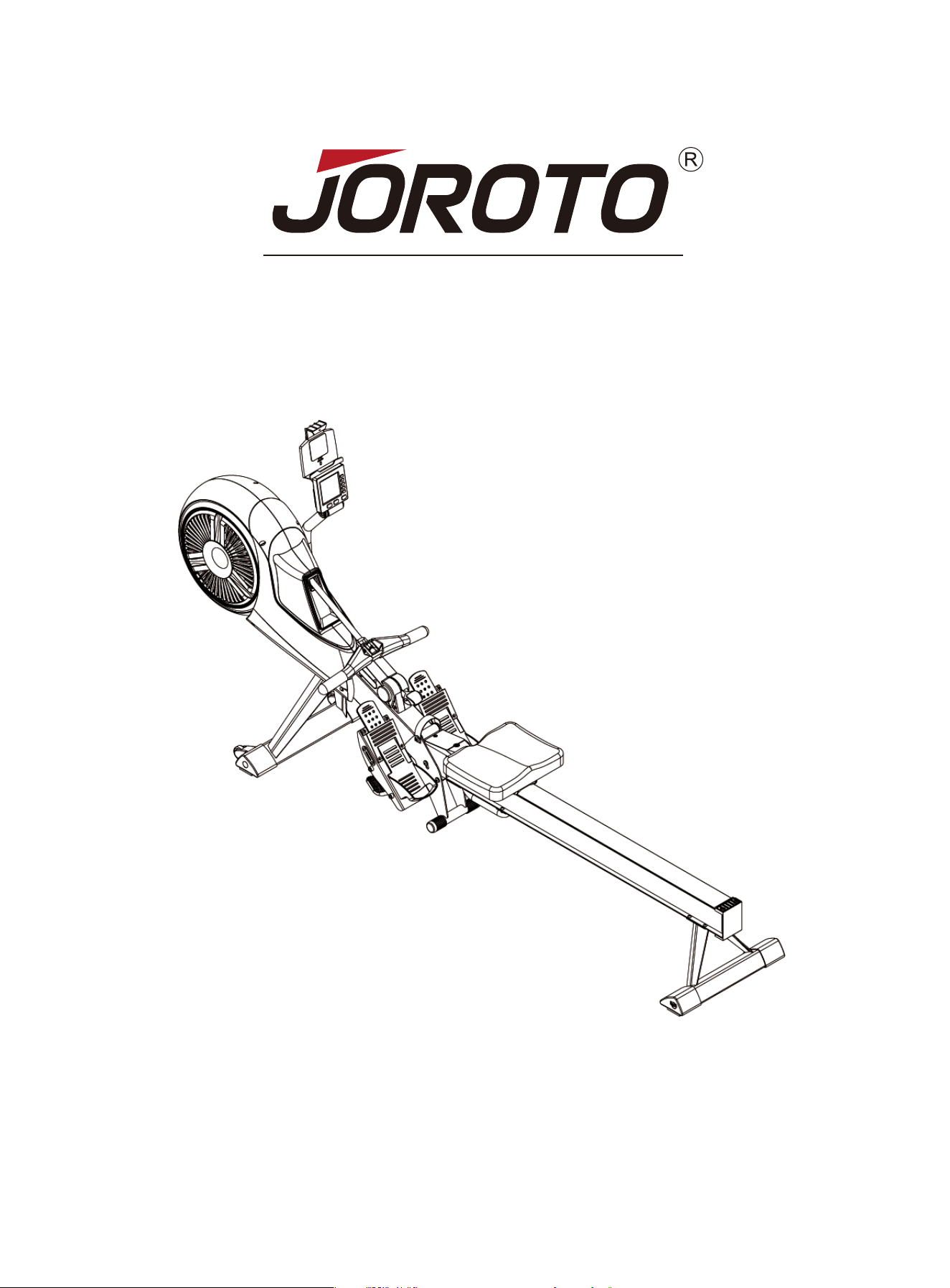
JOROTO-MR60
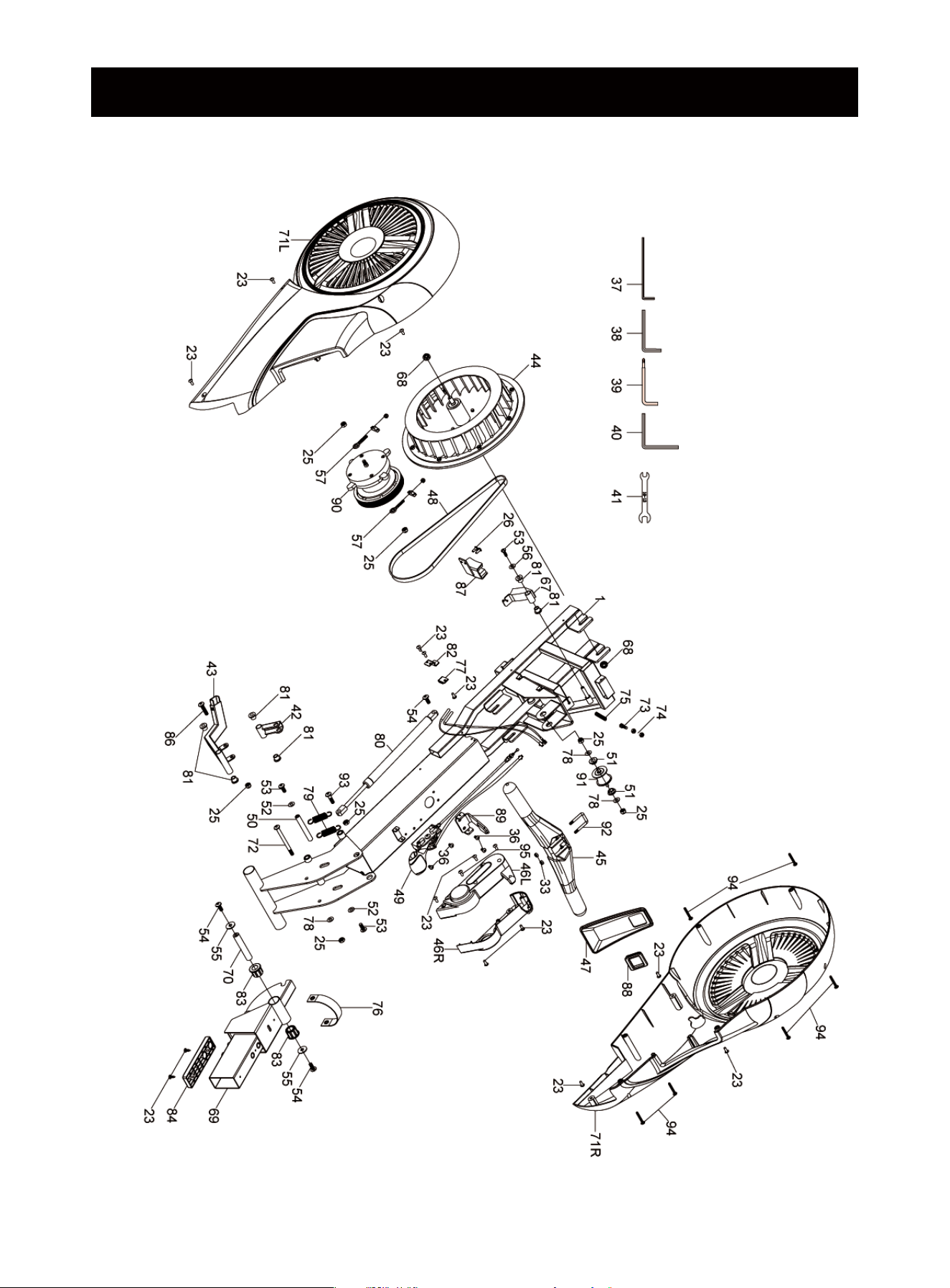
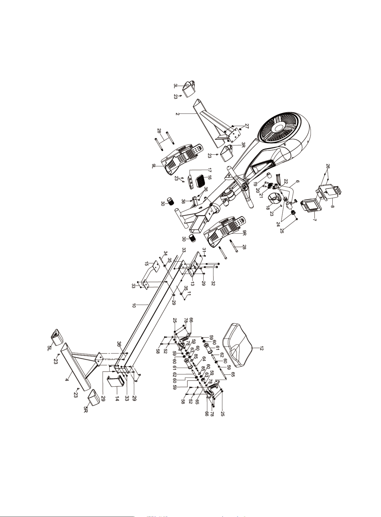
EXPLODED-VIEW & PARTS LIST
1
2

NAME
Main Frame
Front Stabilizer
End Caps for Front Stabilizer L/R
Rear Stabilizer
End Caps for Rear Stabilizer L/R
Monitor-Supporting Tube
Monitor
Ipad Holder
Pedal L/R
Rail
Nylon Nut
Seat
Front Rail Cover
Back Rail Cover
Portable Tube
Release Pad
Fixing Tube for Pedals
Decorative Cover
Felt Pad
Hex Screws
Clamp Ring
Hex Screws
Flat Head Self-tapping Screw
End Cap of Monitor Supporting Tube
Nylon Nut
Large Flat Head Screws
Round Head Socket Head Cap Screws
Hexagon Socket Head Screws
Round Head Socket Head Cap Screws
End Cups
Cross Half Round Head Screw
Hexagon Socket Head Cap Screws
Nylon Nut
Cross Half Round Head Screw
Buffer Pad
Round Head Socket Head Cap Screws
L-Wrench
L-Wrench
L-Wrench
L-Wrench
Open End Wrench
Pedal-Connecting Part
Pedal-Connecting Tube
Flywheel
Pulling Handle
Decorative Cover(L/R)
Webbing Decorative Cover
NO.
1
2
3
4
5
6
7
8
9
10
11
12
13
14
15
16
17
18
19
20
21
22
23
24
25
26
27
28
29
30
31
32
33
34
35
36
37
38
39
40
41
42
43
44
45
46
47
SPEC.
-
-
-
-
-
-
-
-
-
-
M5
-
-
-
-
-
-
-
-
M8*25
-
M8*75
ST5*15
-
M8
M5*15
M8*16
M12*140
M6*15
Φ31.8
M5*12
M10*125
M6
M5*60
-
M6*10
4MM
8MM
6MM(Cross Head)
6MM
10-13
-
-
-
-
-
-
NAME
Hauptrahmen
Vorderer Stabilisator
Endkappen für vorderen Stabilisator (L/R)
Hinterer Stabilisator
Endkappen für hinterer Stabilisator (L/R)
Display-Stützrohr
Display
Ipad-Ständer
Pedal L/R
Schiene
Nylonmutter
Sitz
Vordere Schienenkappe
Rückenschienenkappe
Tragbare Röhre
loslassen Pad
Pedale-Halterohr
Dekorative Abdeckung
Filzunterlage
Sechskantschrauben
Klemmring
Sechskantschrauben
Selbstschneidende Flachkopfschraube
Display-Stützrohrs-Endschale
Nylonmutter
Große flache Schrauben
Rundkopf-Innensechskantschrauben
Innensechskantschrauben
Rundkopf-Innensechskantschrauben
Endkappe
Kreuzschraube
Innensechskantschrauben
Nylonmutter
Kreuzschlitzschraube
Pufferauflage
Rundkopf-Innensechskantschrauben
L-Schlüssel
L-Schlüssel
L-Schlüssel
L-Schlüssel
Offener Schraubenschlüssel
Pedal-Verbindungsteil
Pedal-Verbindungsrohr
Schwungscheibe
Zuggriff
Dekorative Abdeckung (L/R)
Dekorative Abdeckung
QTY.
1
1
1/1
1
1/1
1
1
1
1/1
1
1
1
1
1
1
1
1
1
1
2
1
1
22
2
14
4
4
4
8
2
1
2
8
1
2
11
1
1
1
1
1
1
1
1
1
1/1
1
NOM
Cadre principal
Stabilisateur avant
Embouts pour stabilisateur avant L/R
Stabilisateur arrière
Embouts pour stabilisateur arrière L/R
Tube de support de moniteur
Moniteur
Porte-Ipad
Pédale L/R
Rail
Écrou en nylon
Sièges
Couvercle de rail avant
Couverture de rail arrière
Tube portatif
Tampon de dégagement
Tube de fixation pour pédales
Couverture décorative
Tapis feutré
Vis hexagonales
Anneau de serrage
Vis hexagonales
Vis autotaraudeuse à tête plate
Embout du tube de support du moniteur
Écrou en nylon
Grandes vis à tête plate
Vis d'assemblage à tête creuse à tête ronde
Vis à tête à six pans creux
Vis d'assemblage à tête creuse à tête ronde
Capuchons d'extrémité
Vis à tête demi-ronde cruciforme
Vis d'assemblage à tête à six pans creux
Écrou en nylon
Vis à tête demi-ronde cruciforme
Tampon tampon
Vis d'assemblage à tête creuse à tête ronde
Clé en L
Clé en L
Clé en L
Clé en L
Clé à fourche
Pièce de connexion de pédale
Tube de connexion de pédale
volant d'inertie
Poignée de traction
Couverture décorative (L/R)
Couverture décorative en sangle
3

NAME
Belt
Handlebar Cable for Resistance Adjustment
Pedal Fixed Shaft
Sleeve
Washer
Screw
Round Head Socket Head Cap Screws
Washer
Washer
Adjustable Fixing-Screw
Round Head Socket Head Cap Screws
Scroll Wheel Outer Sleeve
Bearings
Upper Scroll Wheel
Scroll Wheel Inner Sleeve
Lower Scroll Wheel
Lower Scroll Wheel Screw
Upper Scroll Wheel Schaft
Seat Supporting Pad
Magnet Set
Flange Nut
Rail Connection Pipe
Folding Reels
Belt Cover L/R
Round Head Socket Head Cap Screws
Hexagon Screw
Hexagon Nut
Tension
Webbing Handle
Sensor
Washer
Springs
Cylinder
Magnet Sleeve
Sensor Holder
Folding Reels Cover
Aluminum Rail fixings
Ring
Round Head Socket Head Cap Screws
Magnet Set
Webbing Decorative Ring
Pulling Handle Fixing Plate
Spring Box Set
Webbing Roller
Webbing Hook
Round Head Socket Head Cap Screws
Round Head Self-tapping Screw
Round Head Self-tapping Screw
NO.
48
49
50
51
52
53
54
55
56
57
58
59
60
61
62
63
64
65
66
67
68
69
70
71
72
73
74
75
76
77
78
79
80
81
82
83
84
85
86
87
88
89
90
91
92
93
94
95
SPEC.
-
-
-
-
Φ6*Φ17*1.5
M5*20
M8*20
Φ8*Φ25*1.5
Φ5*Φ18*1.5
-
M6*25
-
608ZZ
-
-
-
M8*28
-
-
-
M10-P1.25
-
-
-
M8*100
M6*25
M6
-
-
-
Φ8*Φ17*1.5
-
-
-
-
-
-
Φ22
M8*55
-
-
-
-
-
-
M8*30
ST5*20
ST5*15
NAME
Riemen
Lenkerkabel zur Widerstandseinstellung
Pedalfester Schaft
Muffe
Unterlegscheibe
Schraube
Rundkopf-Innensechskantschrauben
Unterlegscheibe
Unterlegscheibe
Einstellbare Befestigungsschraube
Rundkopf-Innensechskantschrauben
Scrollrad-Äußere Hülse
Kugellager
Oberes Scrollrad
Scrollrad- Innenhülse
Unteres Scrollrad
Untere Scrollradschraube
Oberen Scrollrads-Schaft
Sitzstützpolster
Magnet-Set
Flanschmutter
Schienen-Verbindungsrohr
Faltrollen
Riemenabdeckung L/R
Rundkopf-Innensechskantschrauben
Sechskantschraube
Sechskantmutter
Magnetron-Zugfeder
Handgriffe
Sensor
Unterlegscheibe
Frühling
Zylinder
Magnethülse
Sensorhalter
Klapprollenabdeckung
Schienenbefestigung
Ring
Rundkopf-Innensechskantschrauben
Magnet-Set
Dekorativer Ring
Handgriffe-Befestigungsplatte
Spring Box-Set
Gurtband-Roller
Gurtband-Haken
Rundkopf-Innensechskantschrauben
Selbstschneidende Rundkopfschraube
Selbstschneidende Rundkopfschraube
QTY.
1
1
1
2
6
1
3
2
1
2
4
6
6
2
2
2
2
2
2
1
2
1
1
1/1
1
1
2
1
1
1
17
2
1
6
1
2
1
2
1
1
1
1
1
1
1
1
6
2
NOM
Courroie
Câble de guidon pour le réglage de la
résistance
Pédale à tige fixe
Douille intérieure
Laveuse
Vis
Vis d'assemblage à tête creuse à tête ronde
Laveuse
Laveuse
Vis de fixation réglable
Vis d'assemblage à tête creuse à tête ronde
Manchon extérieur de la molette de défilement
Roulements
Molette de défilement supérieure
Manchon intérieur de la molette de défilement
Molette de défilement inférieure
Vis de la molette de défilement inférieure
Axe supérieur de la molette de défilement
Coussin de support de siège
Ensemble d'aimants
Écrou de bride
Tuyau de connexion ferroviaire
Moulinets pliants
Couvre-courroie L/R
Vis d'assemblage à tête creuse à tête ronde
Vis hexagonale
Écrou hexagonal
Ressort de tension magnétron
Poignée en sangle
Capteur
Ressorts
Cylindre
Aimant Manches
Support de capteur
Couverture de bobines pliantes
Fixations de rail en aluminium
Bague
Vis d'assemblage à tête creuse à tête ronde
Ensemble d'aimants
Anneau décoratif en sangle
Plaque de fixation de la poignée de tirage
Coffret Printemps
Rouleau de sangle
Crochet de sangle
Vis d'assemblage à tête creuse à tête ronde
Vis autotaraudeuse à tête ronde
Vis autotaraudeuse à tête ronde
4

Nome
Cornice principale
Tubo di supporto anteriore
Tappo del tubo di supporto anteriore (sinistra/destra)
Tubo di supporto posteriore
Tappo del tubo di supporto posteriore (SX/DX)
Espositore
Schermo
Supporto per tablet
Pedale (sinistra/destra)
Tubo di guida in alluminio
Dado in nylon
Cuscino sedile scorrevole
Copertura del rivestimento anteriore del tubo di guida
Copertura del rivestimento posteriore del tubo di guida
Manico del tubo
rilievo di rilascio
Tubo di fissaggio staffa
Copertura decorativa per supporto Schermo
feltro di lana
Vite a Testa Cilindrica ed Esagonale Interno
Anello di tenuta
Vite a testa semicircolare ed esagono interno
Vite autofilettante a testa piatta a croce grande
Monitorare il manicotto dell'albero rotante
Dado in nylon
Vite Phillips a testa piatta grande
Vite Testa tonda con esagono interno
Vite a Testa Cilindrica ed Esagonale Interno
Vite Testa tonda con esagono interno
Tappo per tubo centrale
Vite Phillips a testa tonda
Vite a Testa Cilindrica ed Esagonale Interno
Dado in nylon
Vite Phillips a testa tonda
Pad
Vite Testa tonda con esagono interno
Chiave a L
Chiave a L
Chiave a L
Chiave a L
chiave a forchetta
collegamento della staffa
Tubo di collegamento della staffa
Volante
Sbarra
Copertina decorativa a della maniglia di resistenza (sinistra/destra)
Copertina decorativa alla banda
NO.
1
2
3
4
5
6
7
8
9
10
11
12
13
14
15
16
17
18
19
20
21
22
23
24
25
26
27
28
29
30
31
32
33
34
35
36
37
38
39
40
41
42
43
44
45
46
47
SPEC.
-
-
-
-
-
-
-
-
-
-
M5
-
-
-
-
-
-
-
-
M8*25
-
M8*75
ST5*15
-
M8
M5*15
M8*16
M12*140
M6*15
Φ31.8
M5*12
M10*125
M6
M5*60
-
M6*10
4MM
8MM
6MM(Cross Head)
6MM
10-13
-
-
-
-
-
-
Nombre
Marco Principal
Tubo de Soporte Delantero
Tapón del Tubo de Soporte Delantero (Izdo./Dcho.)
Tubo de Soporte Trasero
Tapón del Tubo de Soporte Trasero (Izdo./Dcho.)
Soporte de Pantalla
Pantalla
Soporte de Tableta
Pedal (Izdo./Dcho.)
Tubo de Riel de Aluminio
Tuerca de Nylon
Cojín de Asiento Deslizante
Cubierta Embellecedora Delantera del Tubo del Riel
Cubierta Embellecedora Trasera del Tubo del Riel
Tubo de Mango
Almohadilla de Liberación
Tubo de Fijación del Estribo
Cubierta Decorativa para Soporte de Pantalla
Fieltro de Lana
Tornillo con Cabeza Cilíndrica y Hexágono Interior
Anillo de Sujeción
Tornillo con Cabeza Semicircular y hexágono interior
Tornillo Autorroscante de Cabeza Plana Grande en Cruz
Manguito del Eje Giratorio de Monitor
Tuerca de Nylon
Tornillo Phillips de Cabeza Plana Grande
Tornillo de Cabeza Redonda con Hexágono Interior
Tornillo con Cabeza Cilíndrica y Hexágono Interior
Tornillo de Cabeza Redonda con Hexágono Interior
Tapón de Tubo Medio
Tornillo Phillips de Cabeza Semicircular
Tornillo con Cabeza Cilíndrica y Hexágono Interior
Tuerca de Nylon
Tornillo Phillips de Cabeza Semicircular
Almohadilla
Tornillo de Cabeza Redonda con Hexágono Interior
Llave en L
Llave en L
Llave en L
Llave en L
Llave de boca
Enlace del Estribo
Tubo de Enlace del Estribo
Volante
Barra
Cubierta Decorativ a de Mango de Resistencia (Izda./Dcha.)
Cubierta Decorativ a de la banda
QTY.
1
1
1/1
1
1/1
1
1
1
1/1
1
1
1
1
1
1
1
1
1
1
2
1
1
22
2
14
4
4
4
8
2
1
2
8
1
2
11
1
1
1
1
1
1
1
1
1
1/1
1
5

Nome
Cintura
Impugnatura e fascia di resistenza
Pedale rotante
Manica
Guarnizione Piatta
Vite Phillips a testa piatta
Vite Testa tonda con esagono interno
Guarnizione Piatta
Guarnizione Piatta
Vite di fermo regolabile
Vite Testa tonda con esagono interno
Boccole a rulli esterne
Cuscinetto
Rullo superiore
Boccola a rulli interna _
Rullo inferiore
Viti a rulli inferiori _
Alberi a rulli superiori
Supporto per sedile
Set magnetico esterno
Dado flangiato
Tubo di collegamento della guida in alluminio
Girevole per piegare
Copricatena (sinistra/destra)
Vite Testa tonda con esagono interno
Vite Esagono esterno
dado esagonale esterno
Molla di tensione del magnetron
Manico a fascia
Sensore
Guarnizione Piatta
Molla di tensione
cilindro
Boccola in lamina magnetica
Supporto per sensori
Copribobina pieghevole
Fissaggio su binario in alluminio
Squillo
Vite Testa tonda con esagono interno
Gioco del magnete
Anello decorativo in tessuto
Piastra di fissaggio della maniglia di traino
Cofanetto di primavera
Rullo per cintura
Gancio Cinch
Vite Testa tonda con esagono interno
Vite autofilettante a testa tonda
Vite autofilettante a testa tonda
NO.
48
49
50
51
52
53
54
55
56
57
58
59
60
61
62
63
64
65
66
67
68
69
70
71
72
73
74
75
76
77
78
79
80
81
82
83
84
85
86
87
88
89
90
91
92
93
94
95
SPEC.
-
-
-
-
Φ6*Φ17*1.5
M5*20
M8*20
Φ8*Φ25*1.5
Φ5*Φ18*1.5
-
M6*25
-
608ZZ
-
-
-
M8*28
-
-
-
M10-P1.25
-
-
-
M8*100
M6*25
M6
-
-
-
Φ8*Φ17*1.5
-
-
-
-
-
-
Φ22
M8*55
-
-
-
-
-
-
M8*30
ST5*20
ST5*15
Nombre
Cinturón
Mango de Resistencia y la banda
Giratorio de los Pedales
Manga
Gásquet Plano
Tornillo Phillips de Cabeza Plana
Tornillo de Cabeza Redonda con Hexágono Interior
Gásquet Plano
Gásquet Plano
Tornillo de Fijación Ajustable
Tornillo de Cabeza Redonda con Hexágono Interior
Casquillo Exterior de Rodillos
Cojinete
Rodillo Superior
Casquillo interior de Rodillos
Rodillo Inferior
Tornillo de Rodillos Inferiores
Eje de Rodillos Superiores
Soporte del Asiento
Juego de Magnéticas Exteriores
Tuerca de Brida
Tubo de Conexión de Riel de Aluminio
Giratoria para Plegar
Cubierta de la Cadena(Izda./Dcha.)
Tornillo de Cabeza Redonda con Hexágono Interior
Tornillo Hexagonal Externo
Tuerca hexagonal externa
Resorte de Tensión de Magnetrón
Mango de la Banda
Sensor
Gásquet Plano
resorte de tensión
cilindro
Casquillo de lámina magnética
Suporte de Sensor
Cubierta de Carretes Plegables
Fijación de Riel de Aluminio
Anillo
Tornillo de Cabeza Redonda con Hexágono Interior
Juego de Imanes
Anillo Decorativo de Cincha
Placa de Fijación de la Manija de Tracción
Conjunto de Caja de Primavera
Rodillo de Correas
Gancho de Cincha
Tornillo de Cabeza Redonda con Hexágono Interior
Tornillo Autorroscante de Cabeza Redonda
Tornillo Autorroscante de Cabeza Redonda
QTY.
1
1
1
2
6
1
3
2
1
2
4
6
6
2
2
2
2
2
2
1
2
1
1
1/1
1
1
2
1
1
1
17
2
1
6
1
2
1
2
1
1
1
1
1
1
1
1
6
2
6
Nombre
Cinturón
Mango de Resistencia y la banda
Giratorio de los Pedales
Manga
Gásquet Plano
Tornillo Phillips de Cabeza Plana
Tornillo de Cabeza Redonda con Hexágono Interior
Gásquet Plano
Gásquet Plano
Tornillo de Fijación Ajustable
Tornillo de Cabeza Redonda con Hexágono Interior
Casquillo Exterior de Rodillos
Cojinete
Rodillo Superior
Casquillo interior de Rodillos
Rodillo Inferior
Tornillo de Rodillos Inferiores
Eje de Rodillos Superiores
Soporte del Asiento
Juego de Magnéticas Exteriores
Tuerca de Brida
Tubo de Conexión de Riel de Aluminio
Giratoria para Plegar
Cubierta de la Cadena(Izda./Dcha.)
Tornillo de Cabeza Redonda con Hexágono Interior
Tornillo Hexagonal Externo
Tuerca hexagonal externa
Resorte de Tensión de Magnetrón
Mango de la Banda
Sensor
Gásquet Plano
resorte de tensión
cilindro
Casquillo de lámina magnética
Suporte de Sensor
Cubierta de Carretes Plegables
Fijación de Riel de Aluminio
Anillo
Tornillo de Cabeza Redonda con Hexágono Interior
Juego de Imanes
Anillo Decorativo de Cincha
Placa de Fijación de la Manija de Tracción
Conjunto de Caja de Primavera
Rodillo de Correas
Gancho de Cincha
Tornillo de Cabeza Redonda con Hexágono Interior
Tornillo Autorroscante de Cabeza Redonda
Tornillo Autorroscante de Cabeza Redonda
To avoid the possible injuries or damage, please read the manual carefully
before using the product! It is strongly recommended that you retain this
manual for future reference.
1. It is important to read this entire manual carefully before assembling and using the
rower. It can be ensured to use this equipment safely and efficiently only if assem-
bled, maintained and used properly. It is your responsibility to ensure that all users
of the equipment are informed of all warnings and precautions.
2. Before starting any exercise program, please consult your doctor to determine if
you have any physical or health conditions that could create a risk to your health and
safety, or prevent you from using this equipment. Your doctor's advice is essential if
you are taking medicines about heart rate, blood pressure or cholesterol.
3. Be aware of your body's signals. Incorrect or excessive exercise can damage your
health. Stop exercising at once if you experience any of the following symptoms:
pain, tightness in your chest, irregular heartbeat, extreme shortness of breath, feel-
ing light-headed, dizziness or nausea. If you have experienced any of these symp-
toms, please consult your doctor before continuing with your exercise program.
4. Keep children and pets away from the equipment. The equipment is only used for
adults.
5. Put the rower on solid and flat ground when you use it, also, you can consider
using an exercise mat under the machine to protect your floor or carpet. For safety,
the equipment should have at least 0.5 meters of free space all around it.
6. Ensure that all nuts and bolts are tightened securely before using this equipment.
Safe usage of the equipment can only be maintained if it is examined regularly for
damage or wear.
7. Always use the equipment as indicated. Please stop using it immediately, if you
find any defective components while assembling or checking the equipment, or hear
any abnormal noise from the equipment during use it. Do not use the equipment until
the problem has been rectified.
IMPORTANT SAFETY INFORMATION
User Manual
7
Thank you for purchasing JOROTO MR60. Wish it will help you to keep the best
status when doing aerobic exercise!

8. Wear suitable sport clothes when using the equipment. Avoid wearing loose
clothes which may get caught in the equipment, or it may restrict the movement to
continue normally.
9. This machine is only used for indoor.
10. The equipment is not applicable to therapeutic.
11. Must be careful when lifting and moving the equipment. Always use proper lifting
technique, and seek assistance if necessary.
12. Check the integrity of guards and safety devices regularly.
13. Be aware of all moving parts of the rowing machine, be careful of pinching your
hands.
Warning !
Strongly recommend that you consult the doctors or do the physical examina-
tion before using the rowing machine to do regular exercise. Pay more atten-
tion if you’re over 35 years old and have never worked out before, or you’re
under pregnancy or there is any issue happened to your body. Read carefully
and follow the precaution, it might cause serious injuries or damage to body if
not following the instructions and warnings above.
Due to the failure to read the precautions carefully, JOROTO will be not
responsible for the injury or other possible injury caused by the user's own
reasons!
8
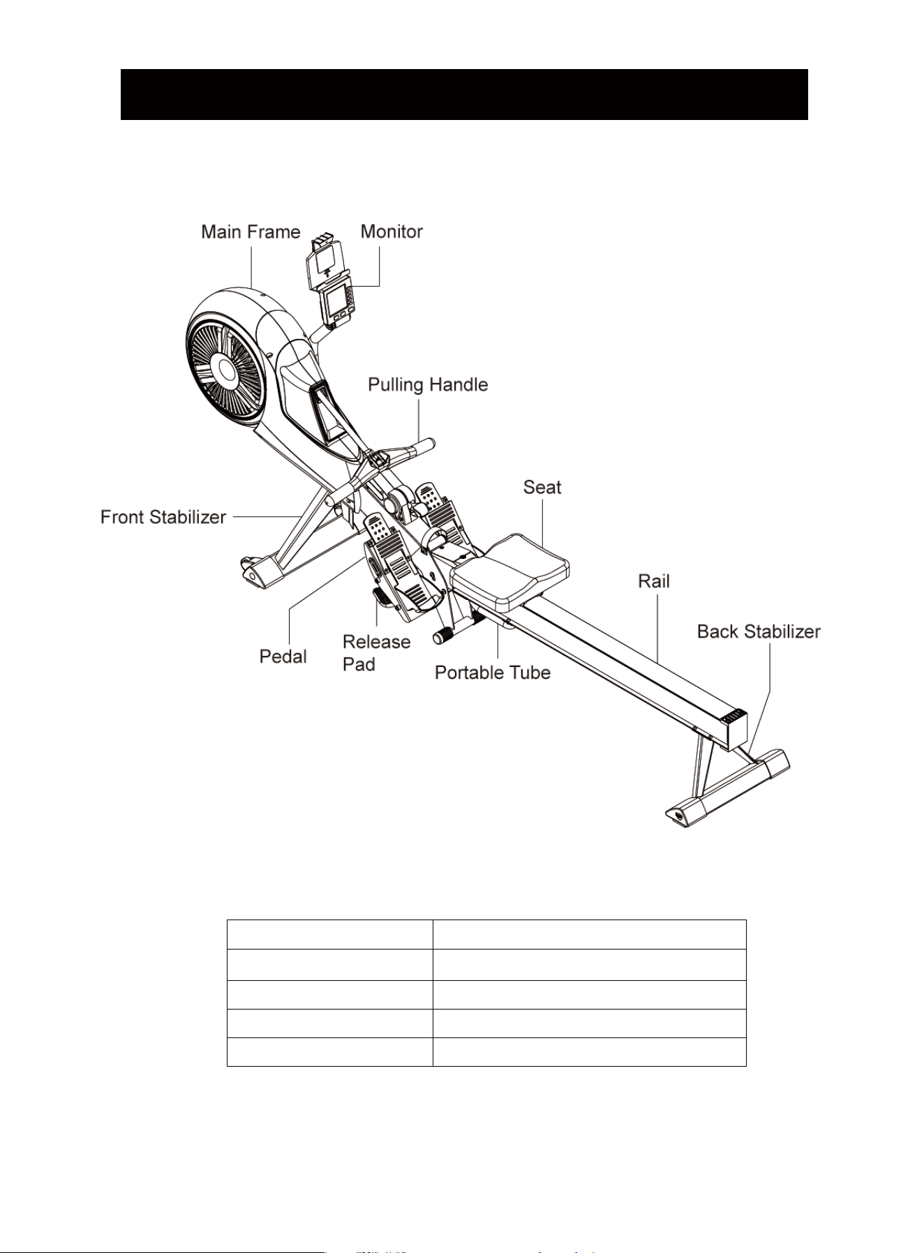
BRIEF INTRODUCTION
Technical Details
Product No.
Item Dimensions
Speed Ratio
Flywheel
Resistance
MR60
80.38×16.73×41 Inches
1: 3.8
Resistance System Wind+Magnetic
10 Levels
9
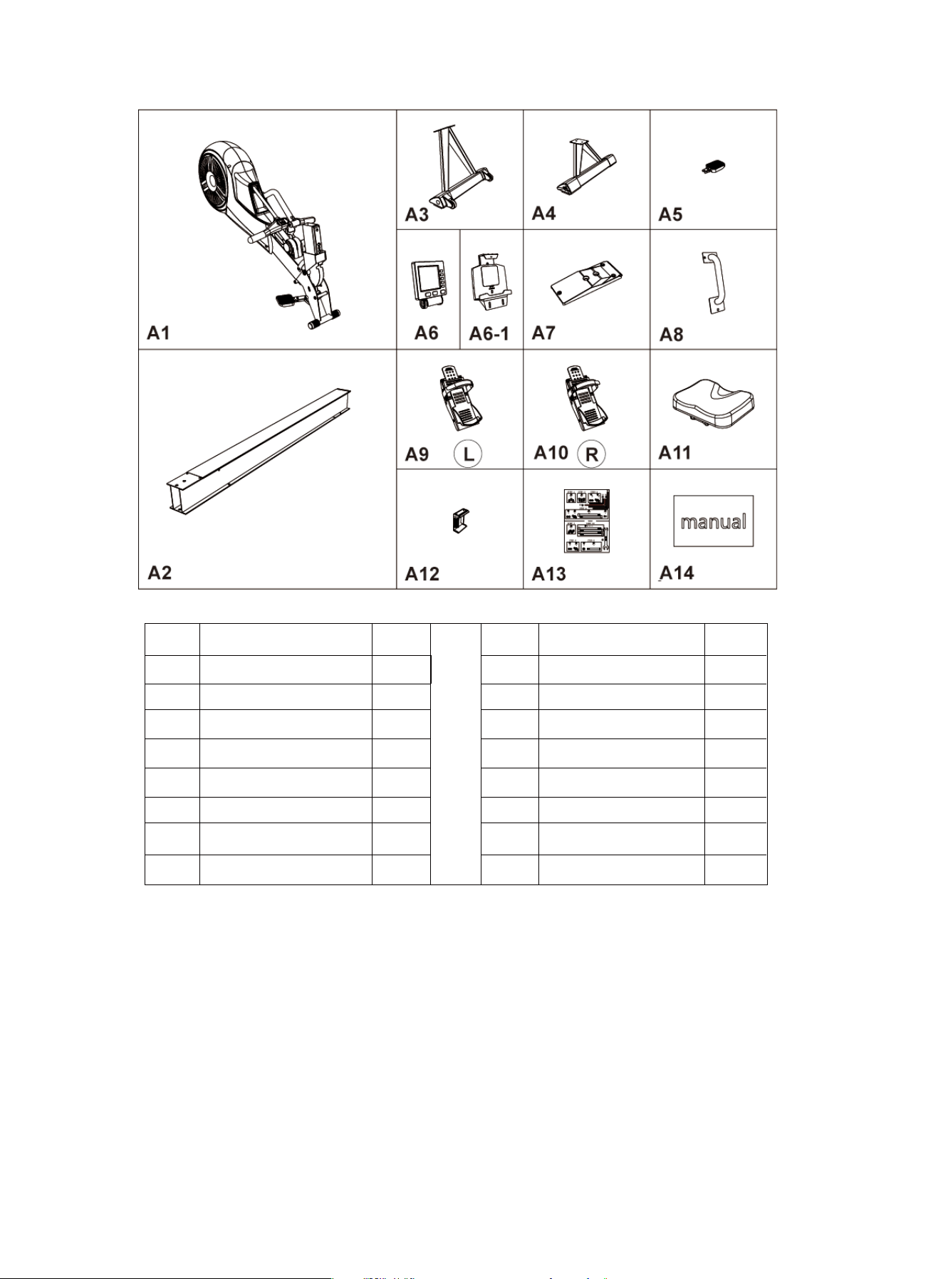
Accessories List
NO.
A1
A2
A3
A4
A5
A6
A6-1
A7
NAME
Main Frame
Rail
Front Stabilizer
Rear Stabilizer
Release Pad
Monitor
IPAD Holder
Front Rail Cover
QTY.
1
1
1
1
1
1
1
1
NO.
A8
A9
A10
A11
A12
A13
A14
NAME
Portable Tube
Left Pedal
Right Pedal
Seat
Back Rail Cover
Tool Kit
Manual
QTY.
1
1
1
1
1
1
1
10
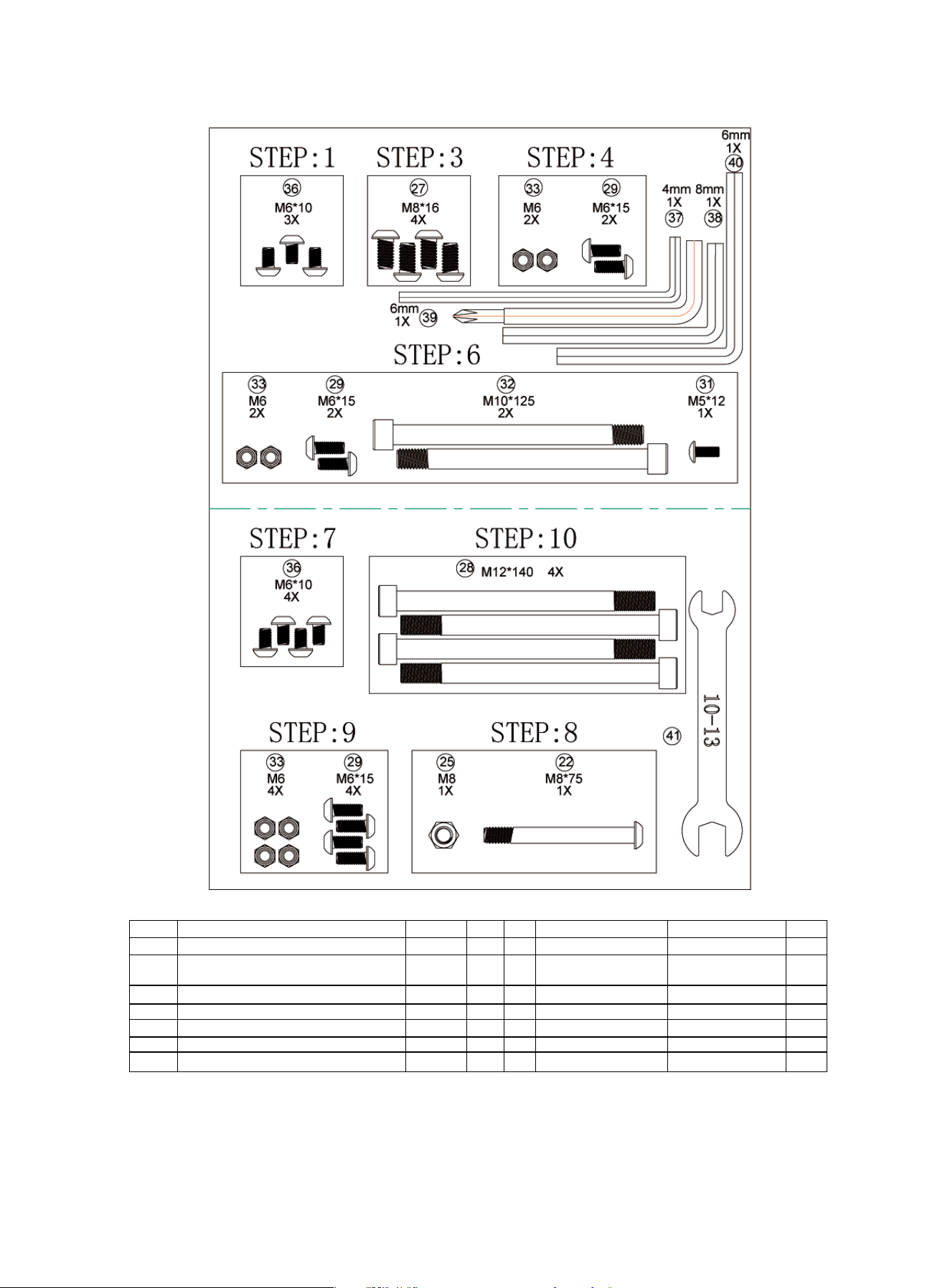
NO.
22
NO.
33
NAME
Nylon Nut
Round Head Socket
Head Cap Screws
SPEC.
M6
QTY.
8
NAME
Hex Screws
Round Head Socket Head Cap Screws
Hexagon Socket Head Screws
Round Head Socket Head Cap Screws
Cross Half Round Head Screw
Hexagon Socket Head Cap Screws
SPEC.
M8*75
QTY.
1
Tool Kit List
M6*10 7361
4
4
8
1
2
37
38
39
40
41
L-Wrench
L-Wrench
L-Wrench
L-Wrench
Open End Wrench
4MM
8MM
6MM(Cross Head)
6MM
10-13
1
1
1
1
1
M8
M8*16
M12*140
M6*15
M5*12
M10*125
Nylon Nut25
27
28
29
31
32
11
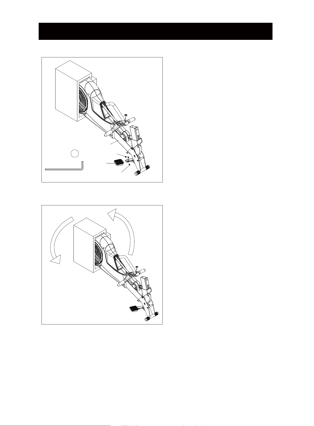
INSTALLATION INSTRUCTION
STEP 1
1. Take the machine out of the box. Do
Not take out the foam at the back.
2. Assemble the Release Pad (A5) to
the Main Frame (A1), screw it with 3
Round Head Socket Head Cap Screws
(36) a little firstly, then tighten them
fully.
STEP 2
Rotate the Main Frame to 180°.
A1
A5
36
36
4mm
1X
37
12
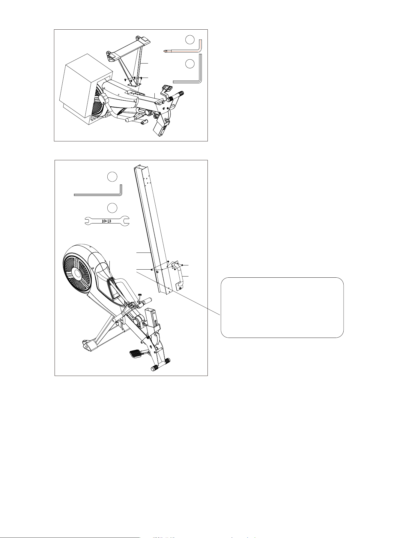
STEP 3
1. Attach the Front Stabilizer (A3) on
the Main Frame (A1), tighten it with
four Round Head Socket Head Cap
Screws (27).
2. Then rotate the Main Frame over to
180°. After that the foam could be
removed.
STEP 4
1. Assemble the Rail (A2) to the Main
Frame (A1).
2. Attach the Portable Tube (A8) on the
Rail (A2), then fix (Do NOT tight up)
them with two Round Head Socket
Head Cap Screws (29) and two Nylon
Nuts (33).
A8
A1
A2
33
29
4mm
1X
37
41
13
NOTE:
Please Only screw the Round Head
Socket Head Cap Screws (29) and
Nylon Nuts (33) firstly, DO NOT
tight them up.
A1
A3
27
40
1X
6mm
39
1X
6mm
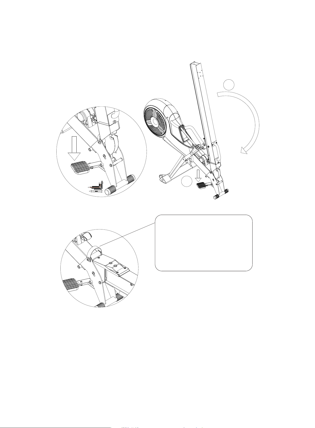
STEP 5
1. Step on the Release Pad to put down the Rail (A2).
2. After hearing a click, the slide rail is fully fixed to the horizontal state.
STEP 6
1. Assemble the Front Rail Cover (A7) to the Rail (A2), screw two Hexagon Socket Head
Cap Screws (32) through the Front Rail Cover (A7) to fix it on the Portable Tube (A8).
NOTE: Be sure that the holes of the Front Rail Cover, the Rail, and the Portable Tube
keep in alignment.
Use two Round Head Socket Head Cap Screw (29) and two Nylon Nuts (33) to fix the Front
Rail Cover (A7) on the Rail (A2).
Use two Cross Half Round Head Screw (31) to fix the Front Rail Cover (A7) on the Main
Frame (A1).
NOTE:
Every time you unfold the slide rail,
please pull up the strap handle.
After you hear a click, the slide rail
is completely fixed to the horizontal
state.
2
1
6mm
1X
4mm
1X
39
37
8mm
1X
38
41
6mm
1X
38
14
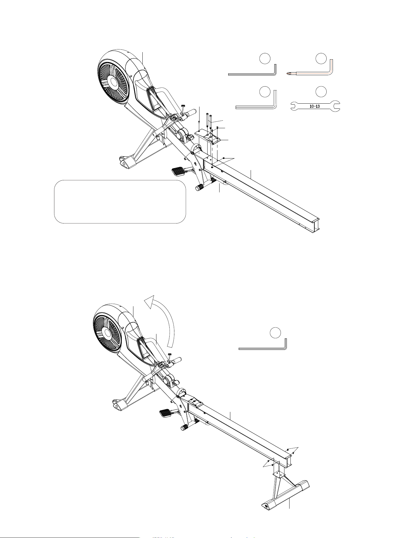
STEP 7
1. Attach the Rear Stabilizer (A4) to the Rail (A2), screw them with four Round Head Socket
Head Cap Screws (36) and then tighten them.
2. Rotate the monitor-supporting tube (6) to an appropriate position to assemble the monitor.
2. Now, tighten the Round Head Socket Head Cap Screws (29) and Nylon Nuts (33) fully.
A8
A7
A2
A1
31
32
29
33
4mm
1X
37
41
8mm
1X
38
6mm
1X
39
A2
A11
A1
6
36
36
After fixing the Front Rail Cover (A7),
tighten the screws in STEP D.
15
4mm
1X
37
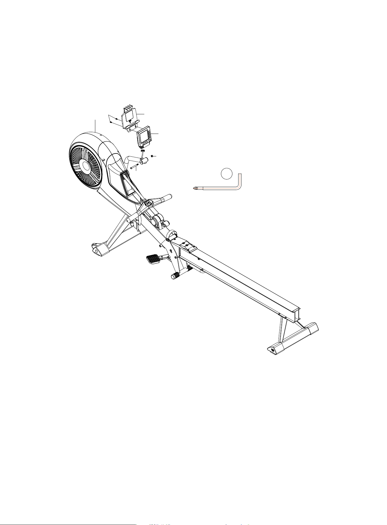
STEP 8
1. Attach the Monitor (A6) on the Main Frame (A1), use one Hex Screw (22) and one
Nylon Nut (25) to fix it.
2. Connect the sensor cable from the Main Frame (A1) to the Monitor (A6).
3. Take off two Large Flat Head Screws (26) from the back of the Monitor (A6), then attach
the Ipad Holder (A6-1) on the Monitor (A6), use two Large Flat Head Screws (26) to
secure them.
STEP 9
1. Attach the Seat (A11) on the Rail (A2).
2. Attach the Back Rail Cover (A12) on the Rail (A2), use four Round Head Socket Head
Cap Screws (29) and Nylon Nuts (33) to fix it.
A1
A6-1
A6
26
25
22
6mm
1X
39
16
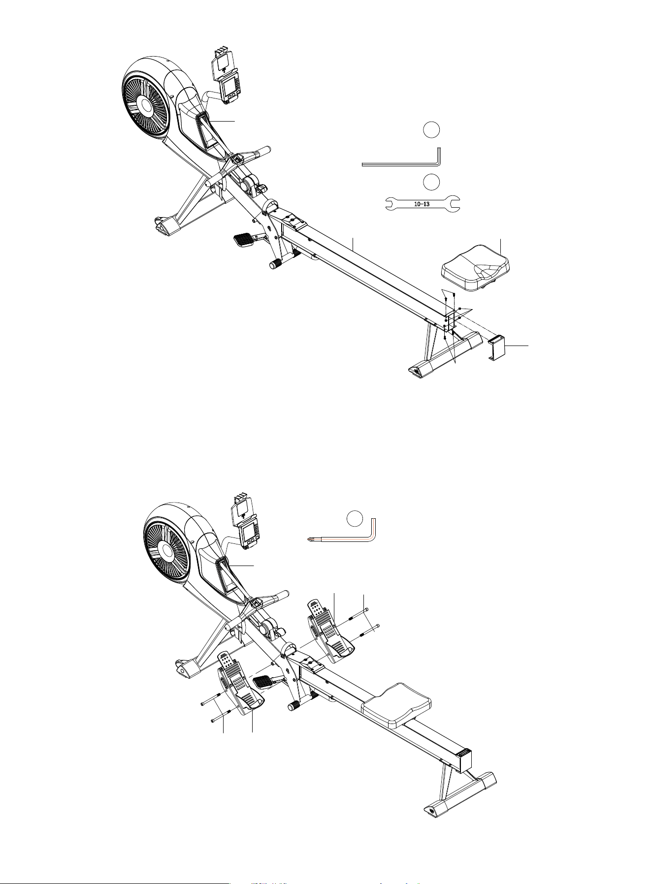
STEP 10
1. Attach the Pedal(A9) to the left side hole of the Main Frame(A1), use two Hexagon
Socket Head Screws(28) to fix it.
2. Use the same method to assemble the Pedal(A10).
A1
A10
A9
28
28
6mm
1X
39
17
A12
A11
A1
A2
29
33
29
4mm
1X
37
41
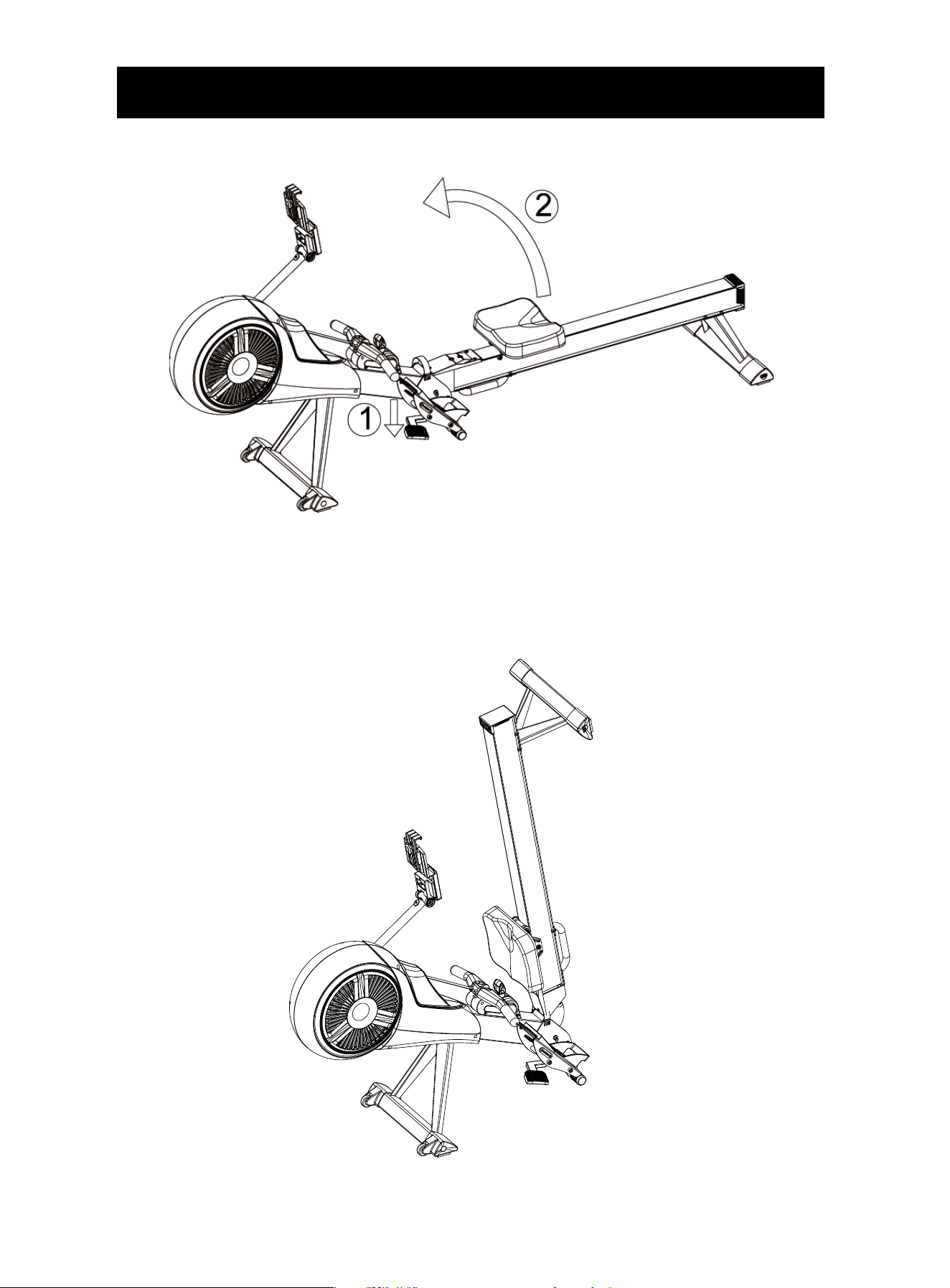
FOLDING INSTRUCTION
① Push down the Release Pad by foot.
② Lift the Rail up slightly.
NOTE: Keep body away from the rail when lifting it up to avoid getting hurt.
18
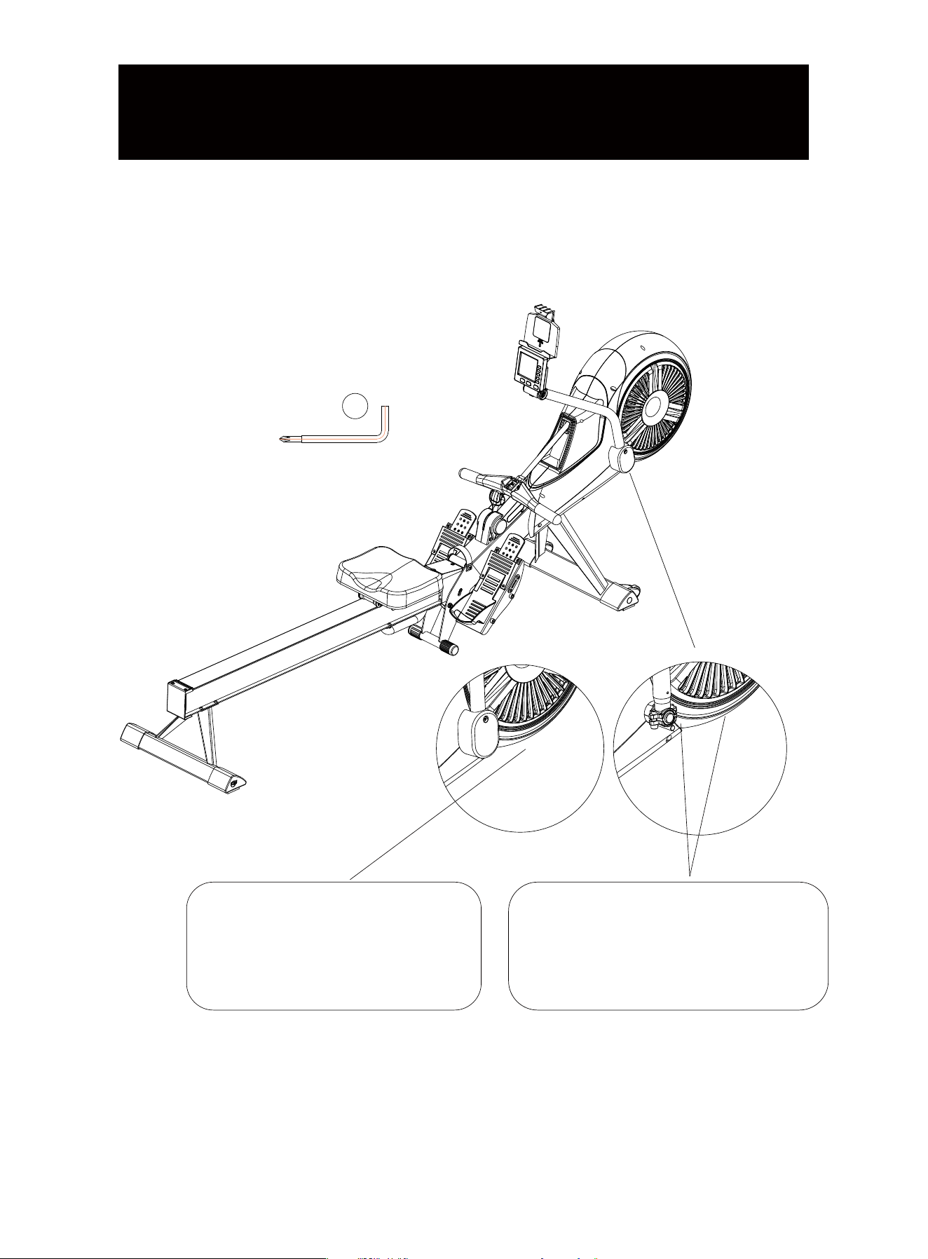
If the Monitor-Supporting Tube get loose or becomes easy to fall off when using, you can
take off the cover under the tube, and use the L-Wrench(39) to tighten the two screws on
the tube.
6mm
1X
39
Use L-Wrench(6MM) to loose the
screws on the cover of the tube,
then remove the cover.
Use L-Wrench(6MM) to tighten the
two screws a little bit until the tube is
fixed.
19
MAINTENANCE OF THE
MONITOR-SUPPORTING TUBE
DISPLAY OPERATION MANUAL
2. APP OPERATION
1) Search "KINOMAP" in the mobile app store to download the app.
2) After the download is complete, open the APP and register your personal information,
turn on the Bluetooth of your mobile phone, and make sure that the monitor is powered on
and awake.
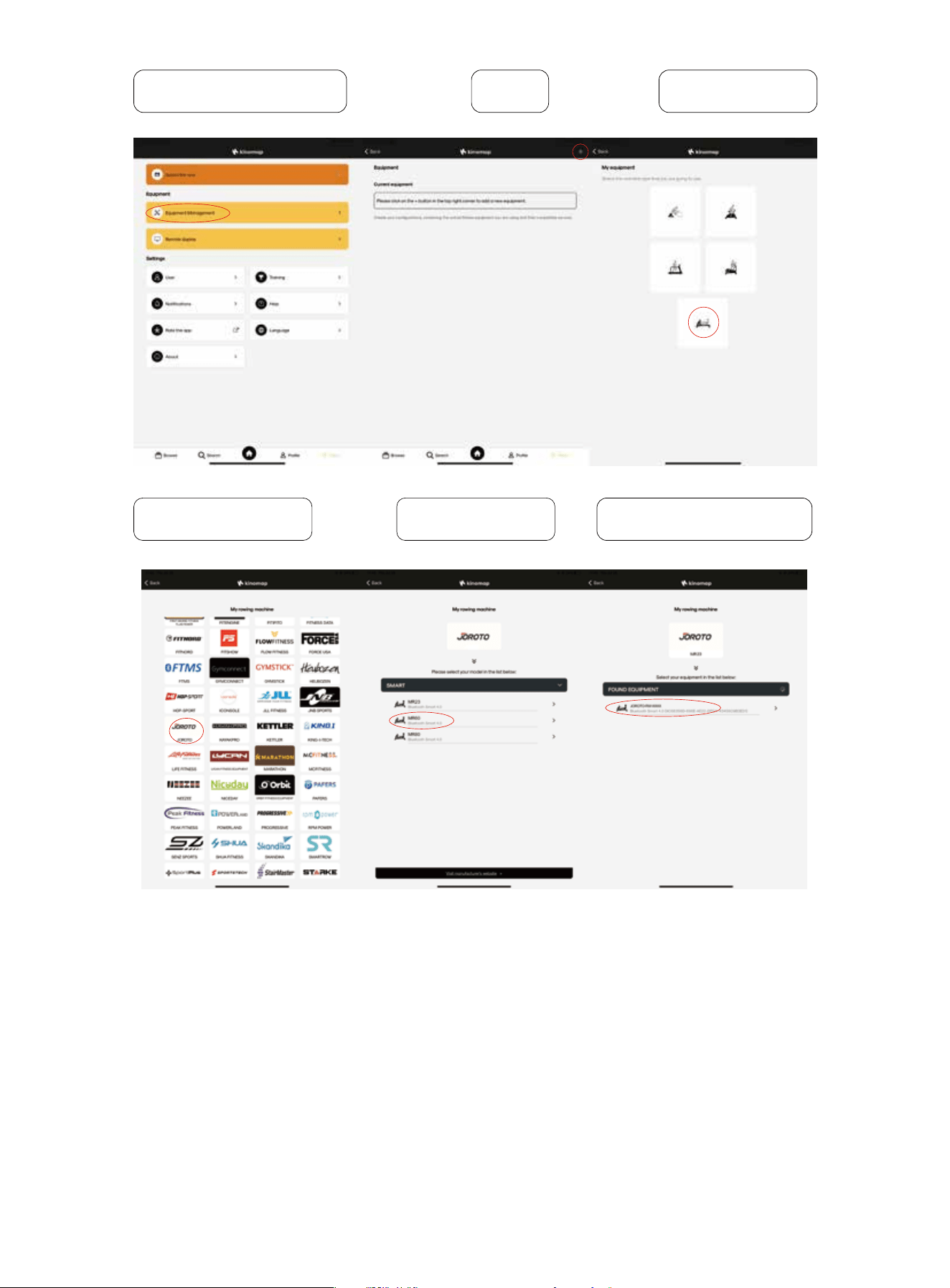
3) Add sports equipment, the specific operations are as follows:
1. BLUETOOTH
1) Working frequency: This wireless transmitter is a Bluetooth 4.2 device. Its operating
frequency is 2.4GHZ.
2) Phone System Requirements:
a. IOS system must not be lower than version 7.1, and it needs to support Bluetooth 4.2,
iPhone4S or above mobile phone version.
b. Android system requires version 4.3 or above, and needs to support Bluetooth 4.2.
3) In order to ensure the authenticity and effectiveness of the data recording on the mobile
phone, the wireless transmitter records the user's data and sends it to the mobile APP only
when the monitor is connected to the mobile phone. Before using the device, please connect
the App to the Bluetooth of the monitor to ensure the authenticity of the data recorded in the
mobile app.
4) When the monitor has not received any signal for 2 minutes, it will go into sleep mode. In
sleep mode, the mobile phone will not be able to search for displays. Continue to use the
device or press the button to wake the monitor, the mobile phone can rediscover and
connect to the monitor again.
5) When the monitor is successfully connected to the APP, it will turn off the screen and all
data will be displayed on the APP.
6) After connecting the APP, if you need to use the monitor again, you need to exit the appli-
cation and turn off the Bluetooth of the mobile phone.
20
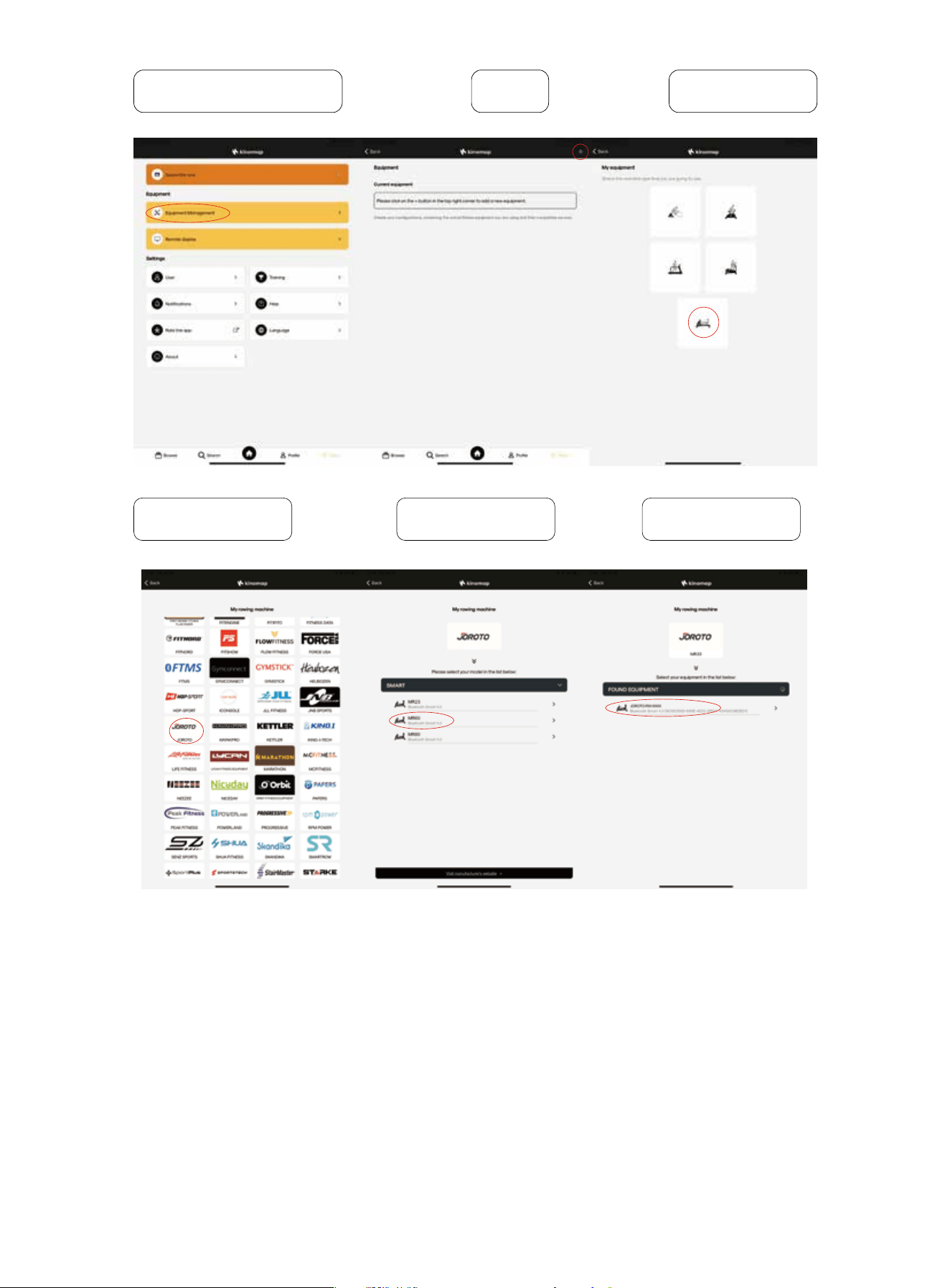
4) After the equipment is connected, choose the scene you like and start your workout!
Equipment Management
Select “JOROTO” Select “MR60” Found Equipment
Rowing Machine+
21
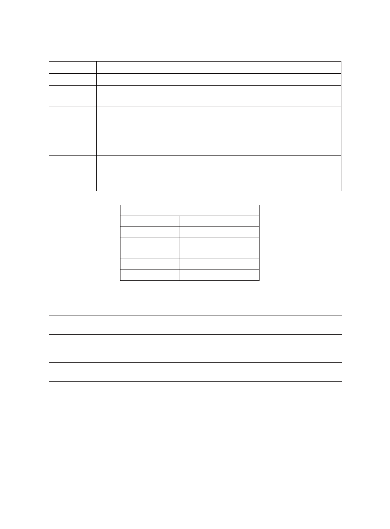
3. OPERATION OF DISPLAY
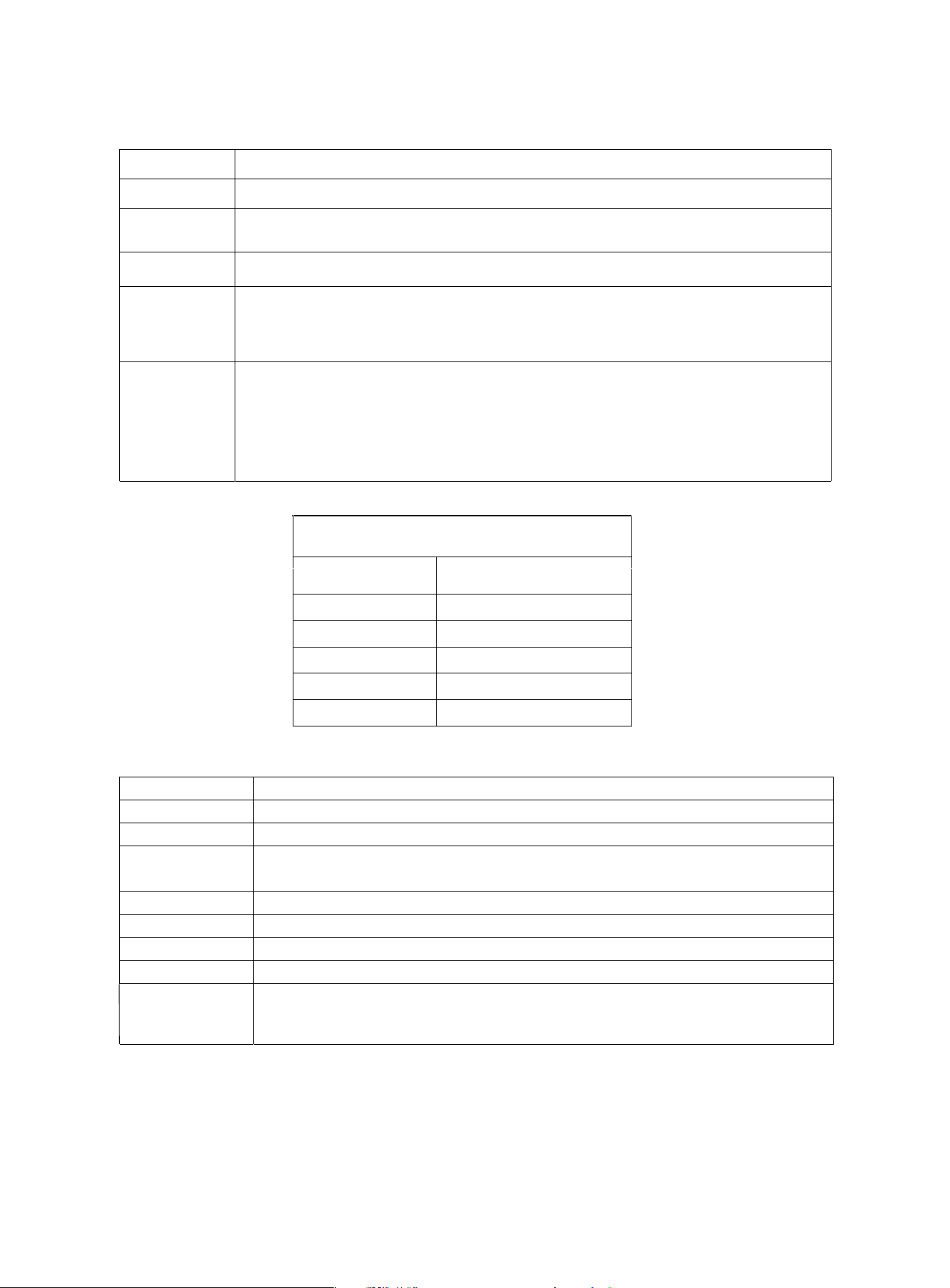
Key Function
Display Function
ITEM
FUNCTION
MODE
ENTER
UP / Down
RESET
RECOVERY
Press this button to switch between Time and Time/500m functions, Pulse and RPM functions, switch
Distance and WATT functions, switch Strokes and total Strokes functions.
Press the MODE button to switch to the function you want to clear, and then press the RESET button
to clear the function values (time, Strokes, distance, calories and pulse values). Press and hold the
RESET button to restart the monitor, and all the values of the monitor will be reset to zero (except for
the total strokes, which will be reset to zero after reinstalling the battery).
Press this button to test the user's heart rate recovery ability after exercise. After workout, keep
wearing the heart rate chest strap. When the heart rate value is displayed on the monitor, press this
button to start the heart rate recovery function. The recovery state represented by the F value is as
follows: (Press the RESET key to switch back to the main display screen).
Press this button to select Time, Strokes, Distance, Calories and Pulse functions.
Press this button to set target values for Time, Strokes, Distance, Calories and Pulse rate.
Display the time the user has exercised.
Display the time required for the user to exercise 500 meters.
Display number of strokes.
Display the distance the user has exercised.
Display the power produced by trainer.
Display the number of calories burned by the user.
Display the Revolutions the user has exercised per minute.
Display the user's heart rate value (please wear the Bluetooth heartbeat chest strap before measuring
the heart rate, the measurement value cannot be used as a medical basis).
Display the accumulated exercise times of the user for multiple exercises, and the value returns to
zero after reinstalling the battery.
1.0
1.0<F<2.0
2.0≤F≤2.9
3.0≤F≤3.9
4.0≤F≤5.9
6.0
Excellent
Normal
Good
Not so good
Bad
Poor
Reference of Heartbeat Recovery Function
TIME
TIME/500M
STROKES
TOTAL STROKES
DISTANCE
WATT
CALORIES
RPM
PULSE
22

TARGET VALUE SETTING
This monitor has five target training modes: Time, Strokes, Distance, Calories And Pulse(set
when not exercising).
1. Target TIME Setting
1) Press the "Mode" button to switch to the "Time" function.
2) Press the "UP/DOWN" button to set the target time (press and hold the UP/DOWN button
to speed up the setting). When the desired time is reached, stop button. Then start using the
machine and the display will start to count down.
3) When the countdown reaches 0 , the monitor emits a beeping sound to remind the user
that the training goal has been completed.
4) If you continue training at this point, the monitor will automatically start counting from 0.
2. Target STROKES Setting
1) Press the "Mode" key to switch to the "Strokes" function.
2) Press the "UP/DOWN" key to set the target strokes (press and hold the UP/DOWN key to
speed up the setting). When the desired strokes is reached, stop button. Then start using the
machine and the display will start to count down.
3) When the countdown reaches 0, the monitor emits a beeping sound to remind the user
that the training goal has been completed.
4) If you continue training at this point, the monitor will automatically start counting from 0.
3. Target DISTANCE Setting
1) Press the "Mode" button to switch to the "Distance" function.
2) Press the "UP/DOWN" button to set the target distance (press and hold the UP/DOWN
button to speed up the setting). When the desired distance is reached, stop button. Then
start using the machine and the display will start to count down.
3) When the countdown reaches 0 , the monitor emits a beeping sound to remind the user
that the training goal has been completed.
4) If you continue training at this point, the monitor will automatically start counting from 0.
4. Target CALORIES Setting
1) Press the "Mode" button to switch to the "Calories" function.
2) Press the "UP/DOWN" button to set the target calories (press and hold the UP/DOWN
button to speed up the setting). When the desired calories is reached, stop button. Then start
using the machine and the display will start to count down.
3) When the countdown reaches 0 , the monitor emits a beeping sound to remind the user
that the training goal has been completed.
4) If you continue training at this point, the monitor will automatically start counting from 0.
23
5. Target PULSE Setting
1)Press the "Mode" button to switch to the "Pulse" function.
2)Press the "UP/DOWN" button to set the target pulse (press and hold the UP/DOWN
button to speed up the setting). When the desired pulse is reached, stop button. Then start
using the machine.
3)When the user's heartbeat is higher than the target pulse value, the monitor will emit a
beeping sound to remind the user.
During the setting process, if you want to modify the target data, press the RESET button to
clear the current setting or press and hold the RESET button to clear all target values, and
then reset according to the above description.
NOTE
1. If the monitor dims or no data displayed, please replace the battery.
2. If there is no signal input or no pressing for 2 minutes, the display will turn off automatically
and go into Sleep Mode.
3. When start training or pressing, the monitor will restart and back to work.
4. When you start training, the monitor will start counting automatically. 4 seconds after you
stop, the monitor will stop counting.
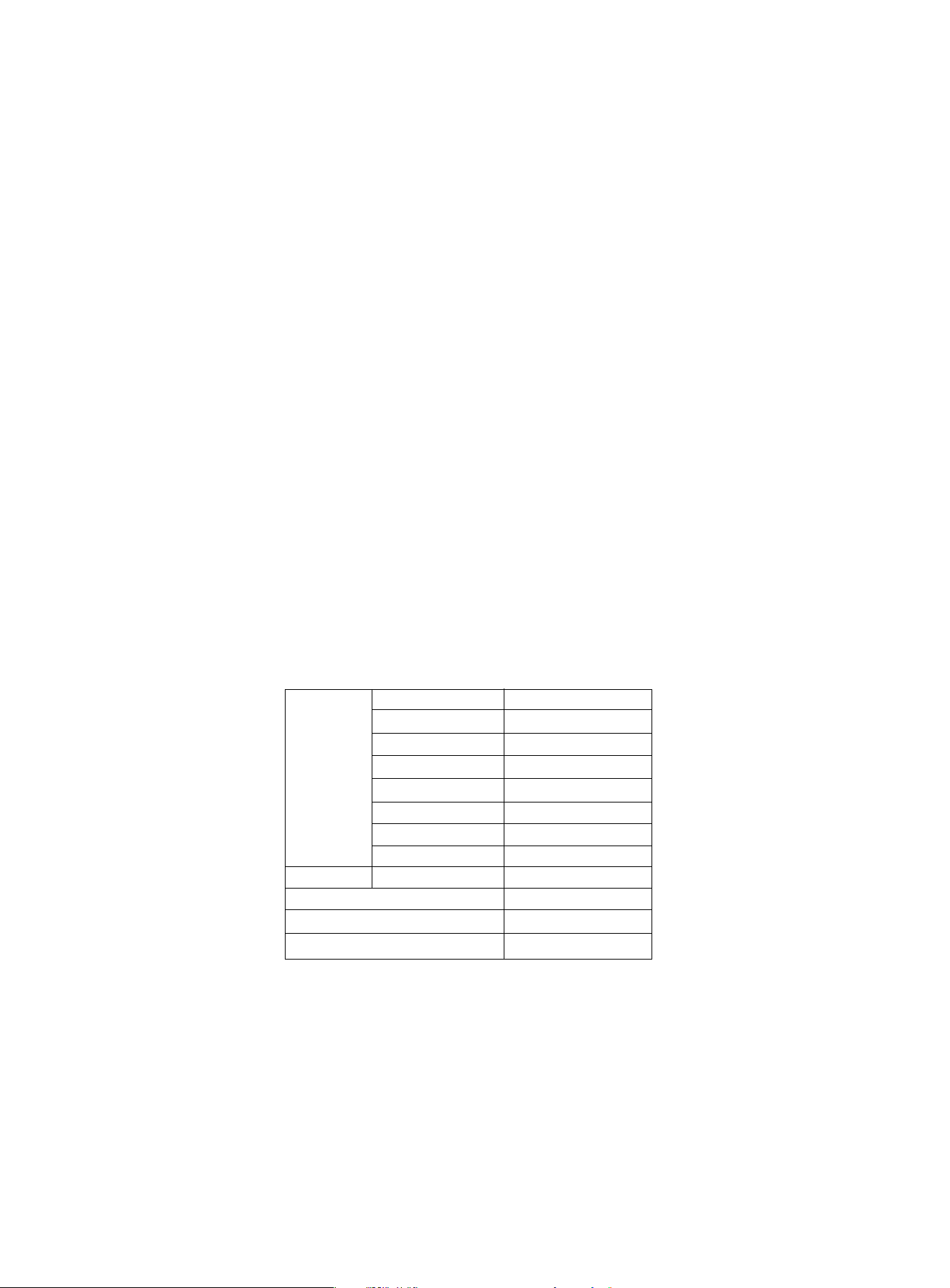
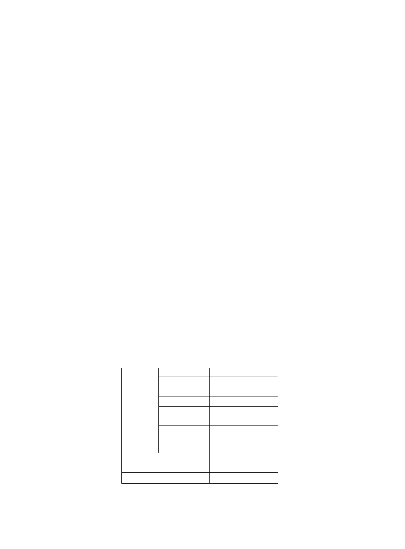
Time
Time/500m
Counting
Total Counting
Distance
Watt
Calories
RPM
Heartbeat
0:00~99:59
0:00~99:59
0~99999
0~99999
0~9999m
0~385 W
0~9999 cal
0~999/min
60~240 BPM
D Battery*2
0°C ~ +40°C
-10°C ~ +60°C
Size of Battery
Working Temperature
Storing Temperature
Functions
Parameter of the monitor
24

25
Changes or modifications not expressly approved by the party responsible for compliance could void the user’s authori-
ty to operate the equipment. This equipment has been tested and found to comply with the limits for a Class B digital
device, pursuant to Part 15 of the FCC Rules.
These limits are designed to provide reasonable protection against harmful interference in a residential installation.
This equipment generates uses and can radiate radio frequency energy and, if not installed and used in accordance
with the instructions, may cause harmful interference to radio communications. However, there is no guarantee that
interference will not occur in a particular installation. If this equipment does cause harmful interference to radio or televi-
sion reception, which can be determined by turning the equipment off and on, the user is encouraged to try to
correct the interference by one or more of the following measures:
‐‐ Reorient or relocate the receiving antenna.
‐‐ Increase the separation between the equipment and receiver.
‐‐Connect the equipment into an outlet on a circuit different from that to which the receiver is connected.
‐‐ Consult the dealer or an experienced radio/TV technician for help.
This device complies with part 15 of the FCC Rules. Operation is subject to the following two conditions:
(1) This device may not cause harmful interference, and
(2) this device must accept any interference received, including interference that maycause undesired operation.
RF Exposure StatementTo maintain compliance with FCC's RF Exposure guidelines, This equipment should
beinstalled and operated with minimum distance of 20cm the radiator your body.
This device and its antenna(s) must not be co-located or operation in conjunction with any other antenna or transmitter.
IC warning:
This device contains licence-exempt transmitter(s)/receiver(s)/ that comply with Innovation Science and Economic
Development Canada's licence-exempt RSS(s). Operation is subject to the following two conditions:
1) this device may not cause interference and
2) this device must accept any interference, including interference that may cause undesired operation of the device.
Radiation Exposure: This equipment complies with Canada radiation exposure limits set forth for an uncontrolled
environment; To maintain compliance with IC's RF Exposure guidelines, This equipment should be. installed and
operated with minimum distance of 5mm the radiator your body. This device and its antenna(s) must not be co-located
or operation in conjunction with any other antenna or transmitter.
Déclaration de l'ISED Canada :
Cet appareil contient des tasmittre (s) / récepteur (s) sans licence / conformes à l'innovationRSS exemptes de licence
de Sciences et Développement économique Canada. L'opération est sous réserve des deux conditions suivantes :
1) cet appareil ne peut pas causer d'interférences et
2) cet dispositif doit accepter toute interférence, y compris peut provoquer le fonctionnement indésirable de l'appareil.
Exposition aux rayonnements : Cet équipement est conforme aux radiations du Canada limites d'exposition pour un
environnement incontrôlé noncé d'exposition RF Pour maintenir le respect des guides d'exposition RF d'IC, cquipment
doit être.installé et actionné avec une distance minimale de 5mm le radiateur de votre corps. Cet appareil et ses
antennes ne doivent pas être co-localisé ou en opération en conjonction avec toute autre antenne ou émetteur.
FCC Warning Statement
Muchas gracias por comprar el MR60 de JOROTO. Le permite mantener una
condición aeróbica óptima.
Para evitar lesiones personales, lea atentamente las siguientes instrucciones
antes de usar este producto. ¡Se recomienda guardar este manual para futuras
consultas!
Nota: Lea atentamente las instrucciones antes de usar y preste atención a las
siguientes precauciones de seguridad
1. Es importante leer todo este manual detenidamente antes de montar y utilizar el
producto. Se puede garantizar el uso seguro y eficiente de este equipo solo si se
ensambla, mantiene y usa correctamente. Es su responsabilidad asegurarse de que
todos los usuarios del equipo estén informados de todas las advertencias y precau-
ciones.
2.Antes de comenzar cualquier programa de ejercicios, consulte a su médico para
determinar si tiene alguna condición física o de salud que pueda crear un riesgo
para su salud y seguridad, o impedirle usar este equipo. El consejo de su médico es
fundamental si está tomando medicamentos para el ritmo cardíaco, la presión arteri-
al o el colesterol.
3. Sea consciente de las señales de su cuerpo. El ejercicio incorrecto o excesivo
puede dañar su salud. Deje de hacer ejercicio de inmediato si experimenta cualqui-
era de los siguientes síntomas: dolor, opresión en el pecho, latidos cardíacos irregu-
lares, dificultad extrema para respirar, sensación de desvanecimiento, mareos o
náuseas. Si ha experimentado alguno de estos síntomas, consulte a su médico
antes de continuar con su programa de ejercicios.
4. Mantenga a los niños y las mascotas alejados del equipo. El equipo solo se utiliza
para adultos.
5. Coloque el producto en un suelo sólido y plano cuando lo use, también puede
considerar usar una colchoneta de ejercicios debajo de la máquina para proteger su
piso o alfombra. Por seguridad, el equipo debe tener al menos 0,5 metros de espa-
cio libre a su alrededor.
6.Asegúrese de que todas las tuercas y pernos estén bien apretados antes de usar
este equipo. El uso seguro solo se puede mantener si se examina periódicamente
para detectar daños o desgaste.
7.Utilice siempre el equipo como se indica. Deje de usarlo inmediatamente si
encuentra algún componente defectuoso mientras ensambla o revisa el equipo, o si
escucha algún ruido anormal del equipo durante su uso. No utilice el equipo hasta
que se haya solucionado el problema.
IMFORMACIÓN DE SEGURIDAD IMPORTANTE
Manual de usuario
26

8.Use ropa deportiva adecuada cuando use el equipo. Evite llevar ropa holgada
que pueda quedar atrapada en la máquina, o puede restringir el movimiento para
continuar con normalidad.
9. Esta máquina solo se usa para interiores.
10. El equipo no es aplicable a terapéuticos.
11.Se debe tener cuidado al levantar y mover el equipo. Utilice siempre la técnica
de elevación adecuada y busque ayuda si es necesario.
12.Compruebe periódicamente la integridad de las protecciones y dispositivos de
seguridad.
13. Tenga cuidado con todas las partes móviles de la máquina. Tenga cuidado de no
pillarse las manos.
¡Advertencia!
Antes de usar esta máquina de remo para hacer ejercicio, se recomienda que
primero realice un examen físico o consulte a un médico, y use esta máquina
de manera razonable de acuerdo con su condición física. Tenga mucho cuida-
do si tiene más de 35 años, nunca ha hecho ejercicio antes, está embarazada
o tiene alguna condición médica. Lea y siga atentamente esta precaución. El
incumplimiento de las advertencias y precauciones de seguridad anteriores
puede provocar lesiones corporales graves.
¡Debido a la falta de lectura atenta de las precauciones, la empresa no se hace
responsable de las lesiones u otras posibles lesiones causadas por las pro-
pias razones del usuario!
27
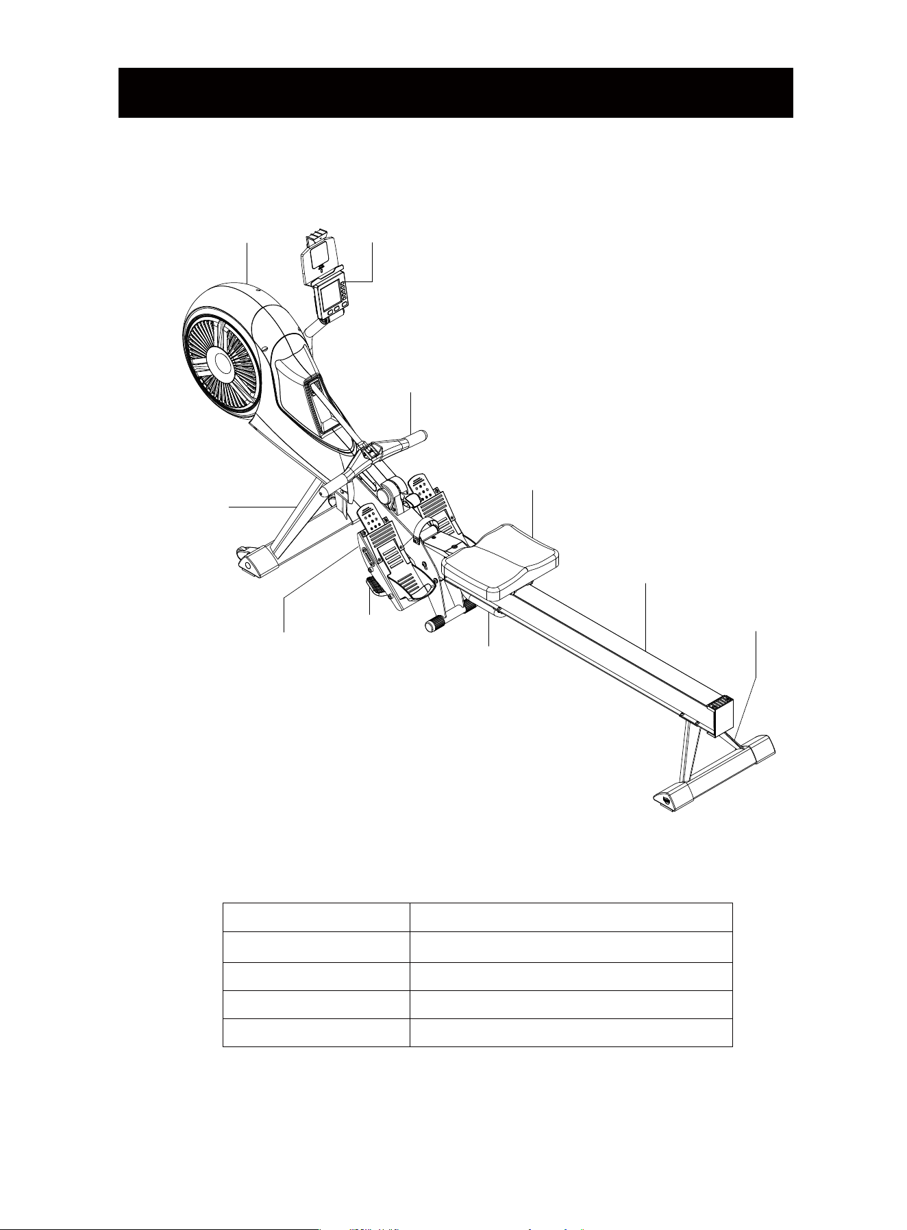
INTRODUCCIÓN DEL PRODUCTO
Marco Principal
Pantalla
Barra
Cojín de Asiento Deslizante
Tubo de Riel de Aluminio
Tubo de Soporte Trasero
Tubo de Mango
Pedal
Almohadilla de
Liberación
Tubo de Soporte
Delantero
Parámetro Técnico
Número de producto
Dimensiones
Relación de Velocidad
Sistema de Resistencia
Nivel de Resistencia
MR60
Desplegado: 2450×510×1250 cm
1:3.8
Viento+Magnético
10
28
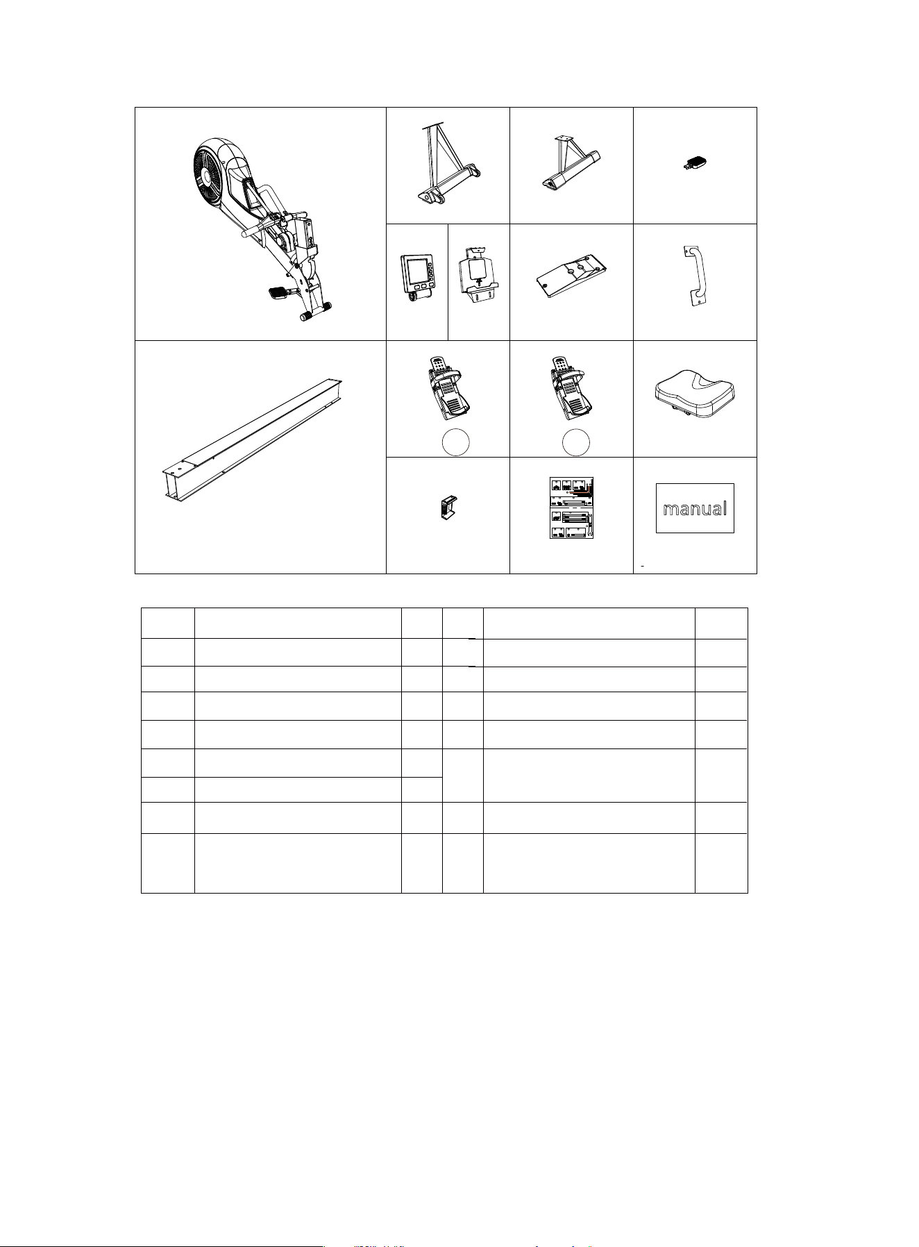
Lista de accesorios
NO.
A1
A2
A3
A4
A5
A6
A6-1
A7
Nombre
Marco Principal
Tubo de Riel de Aluminio
Tubo de Soporte Delantero
Tubo de Soporte Trasero
Almohadilla de Liberación
Pantalla
Soporte para tableta
Cubierta Embellecedora
Delantera del Tubo del Riel
QTY.
1
1
1
1
1
1
1
1
NO.
A8
A9
A10
A11
A12
A13
A14
Nome
Tubo de Mango
Pedal Izquierda
Pedal Derecha
Cojín de Asiento Deslizante
Cubierta Embellecedora
Trasera del Tubo del Riel
Paquete de Tornillos
Manual
QTY.
1
1
1
1
1
1
1
STEP:9
2X
29
M6*15
2X
33
M6
STEP:10STEP:7
4X
36
M6*10
1X
6mm
1X
6mm
38
1X
1X
31
M5*12
2X
32
M10*125
STEP:6
2X
29
M6*15
2X
33
M6
STEP:4
2X
29
M6*15
2X
33
M6
M8
25
1X
22
M8*75
1X
28
M12*140 4X
4mm
1X
STEP:3
3X
27
M8*16
STEP:1
3X
36
M6*10
8mm
39
40
41
37
STEP:8
A3
A4
A5
A6
A6-1
A7
L
A8
A9
A10 A11
A12 A13
A14A2
A1
R
29
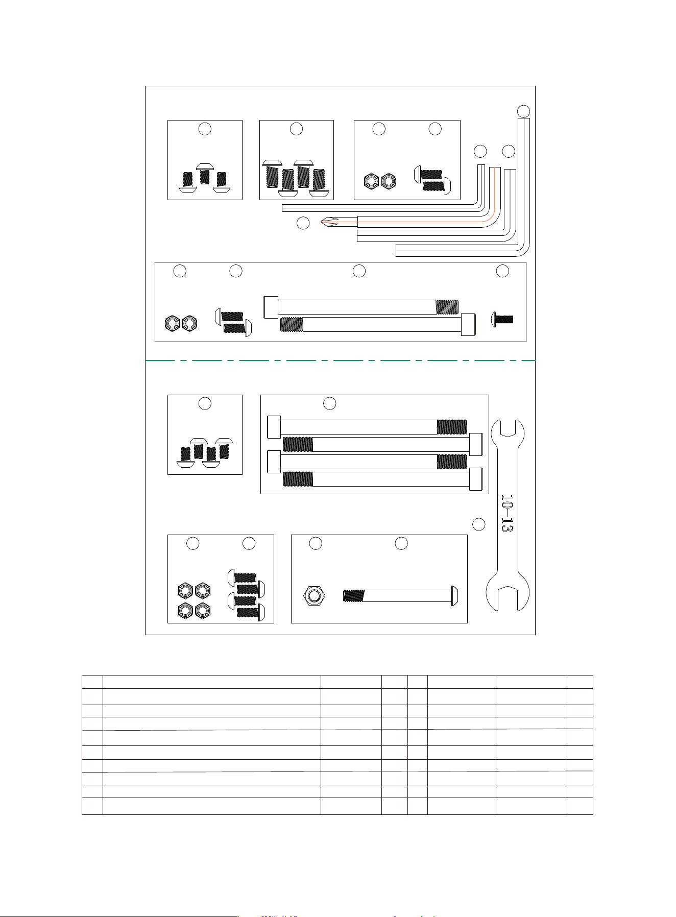
Lista del Paquete de Herramientas
30
No.
22
25
27
28
29
31
32
33
36
Nombre
Tornillo con Cabeza Semicircular y hexágono interior
Tuerca de Nylon
Tornillo de Cabeza Redonda con Hexágono Interior
Tornillo con Cabeza Cilíndrica y Hexágono Interior
Tornillo de Cabeza Redonda con Hexágono Interior
Tornillo Phillips de Cabeza Semicircular
Tornillo con Cabeza Cilíndrica y Hexágono Interior
Tuerca de Nylon
Tornillo de Cabeza Redonda con Hexágono Interior
Especificación
M8*75
M8
M8*16
M12*140
M6*15
M5*12
M10*125
M6
M6*10
QTY.
1
1
4
4
8
1
2
8
7
No.
37
38
39
40
41
Nombre
Llave en L
Llave en L
Llave en L
Llave en L
Llave de boca
Especificación
4MM
8MM
6MM (con croce)
6MM
10-13
QTY.
1
1
1
1
1
38
1X
8mm
37
41
40
39
1X
4mm
M12*140 4X
28
1X
M8*75
22
1X
25
M8
STEP:8STEP:9
29
M6*15
4X
33
M6
STEP:10STEP:7
4X
36
M6*10
1X
6mm
1X
6mm
1X
31
M5*12
2X
32
M10*125
STEP:6
2X
29
M6*15
2X
33
M6
STEP:4
2X
29
M6*15
2X
33
M6
STEP:3
4X
27
M8*16
STEP:1
3X
36
M6*10
4X
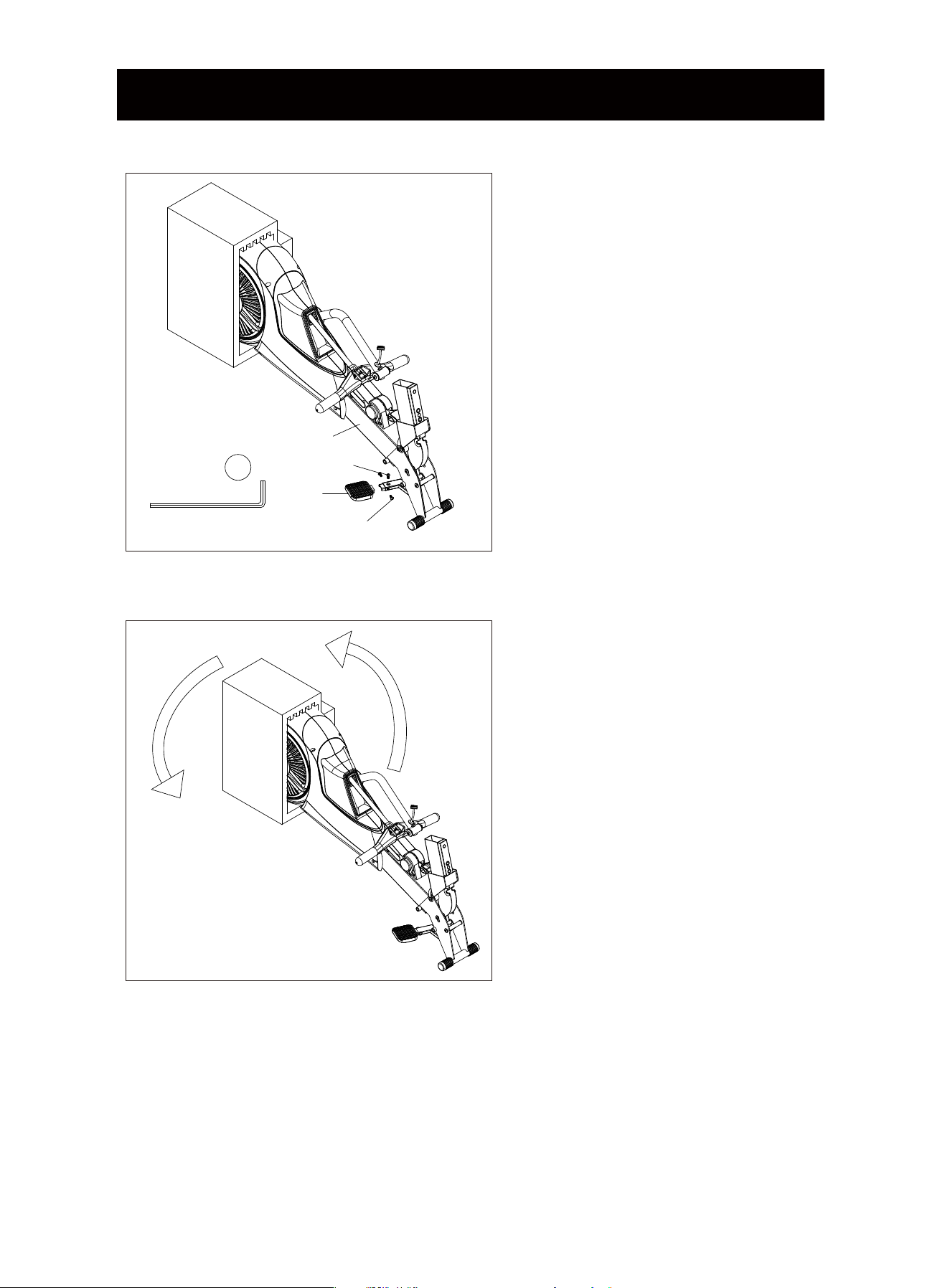
PASOS DE INSTALACIÓN
PASO 1
1. Saque el producto de la caja. No quite
la espuma en la parte posterior.
2. Instale la Almohadilla de Liberación
(A5) en el Marco Principal (A1) y
bloquéela con 3 Tornillos de Cabeza
Redonda con Hexágono Interior (36).
PASO 2
Voltee el Marco Principal 180°.
A1
A5
36
36
31
4mm
1X
37
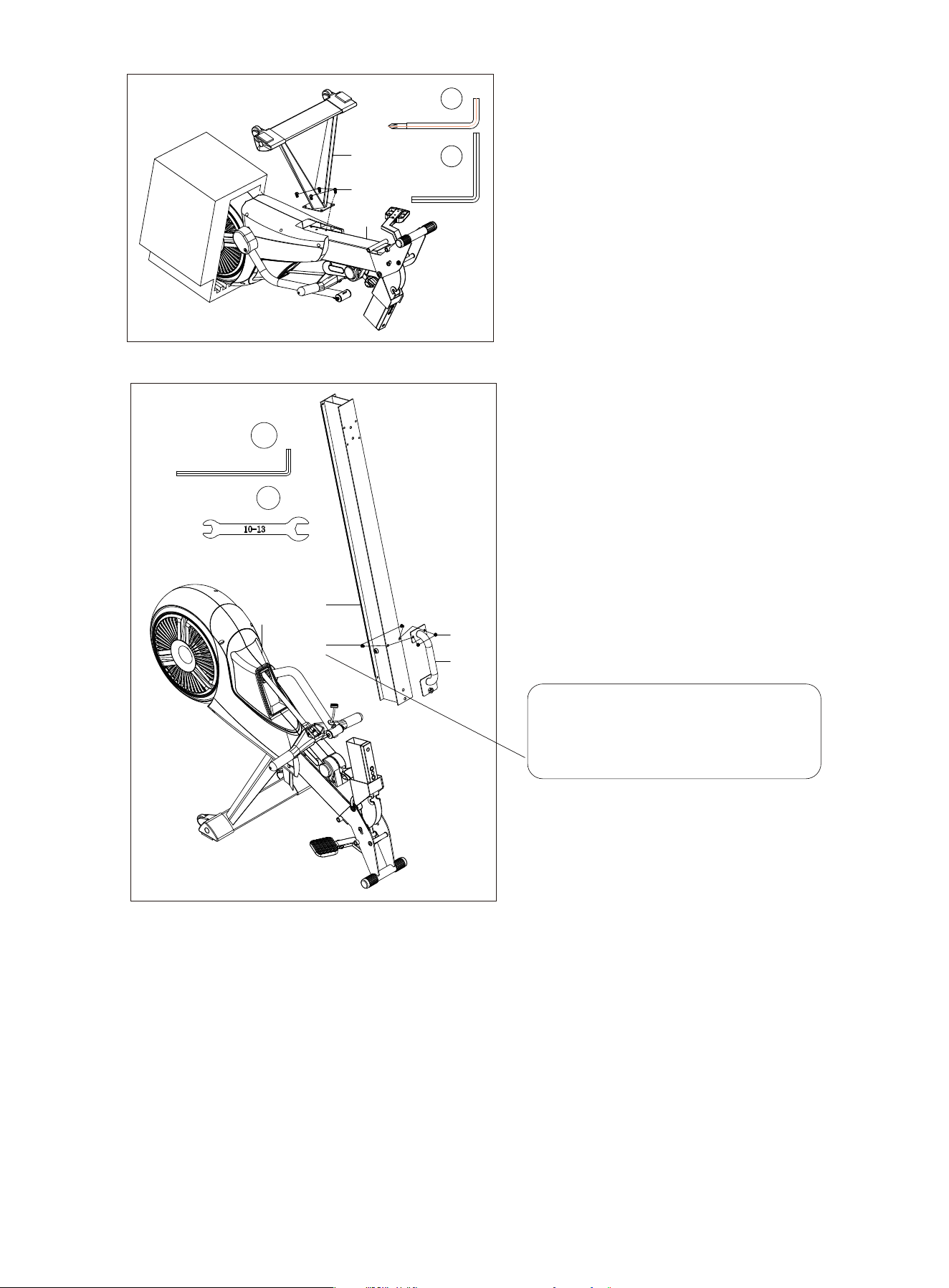
PASO 3
1. Instale el Tubo de Soporte Delantero
(A3) en el Marco Principal (A1) y fíjelo
con 3 Tornillos de Cabeza Redonda
con Hexágono Interior (27).
2. Luego, voltee el Marco Principal 180
° nuevamente y la espuma se puede
tirar.
PASO 4
1. Instale el Tubo de Riel de Aluminio
(A2) en el Marco Principal (A1).
2. Instale el Tubo de Mango (A8) en el
Tubo de Riel de Aluminio (A2) y
bloquéelo (sin apretarlo) con 2 Tornil-
los de Cabeza Redonda con Hexágo-
no Interior y Tuercas de Nylon (33).
A8
A1
A2
33
29
41
Nota:
Instale los tornillos n.° 29 y las tuer-
cas n.° 33, pero no los apriete.
32
A1
A3
27
40
1X
6mm
39
1X
6mm
4mm
1X
37
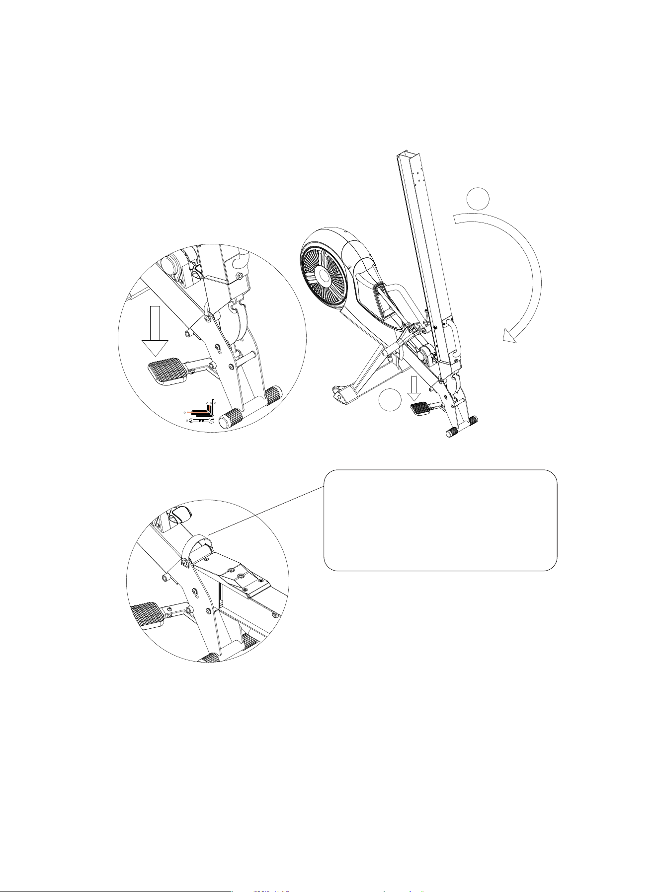
PASO 5
1. Ponga su pie en la Almohadilla de Liberación y presione hacia abajo.
2. Vuelva a colocar el Tubo de Riel de Aluminio (A2) plano hasta que escuche un clic y el
tubo (A2) esté en un estado horizontal.
PASO 6
1. Instale la Cubierta Embellecedora Delantera del Tubo del Riel (A7) en el Tubo del Riel
de Aluminio (A2) y use dos Tornillos con Cabeza Cilíndrica y Hexágono Interior (32) para
pasar a través de la A7 y trabe al Tubo de Mango (A8).
NOTA: Asegúrese de que los orificios de la cubierta del riel delantero, el riel y el tubo
portátil se mantengan alineados.
2. Use dos Tornillos de Cabeza Redonda con Hexágono Interior (29) y dos Tuerca de
Nylon (33) para fijar la Cubierta Embellecedora Delantera del Tubo del Riel al Tubo del Riel
de Aluminio (A2).
NOTA: Después de la instalación, debe
tirar del mango de banda hacia arriba
con la mano para dejar el riel.
Después de un sonido de "clic", el riel
(A2) está en el estado horizontal.
2
1
6mm
1X
4mm
1X
39
37
8mm
1X
38
41
6mm
1X
38
33
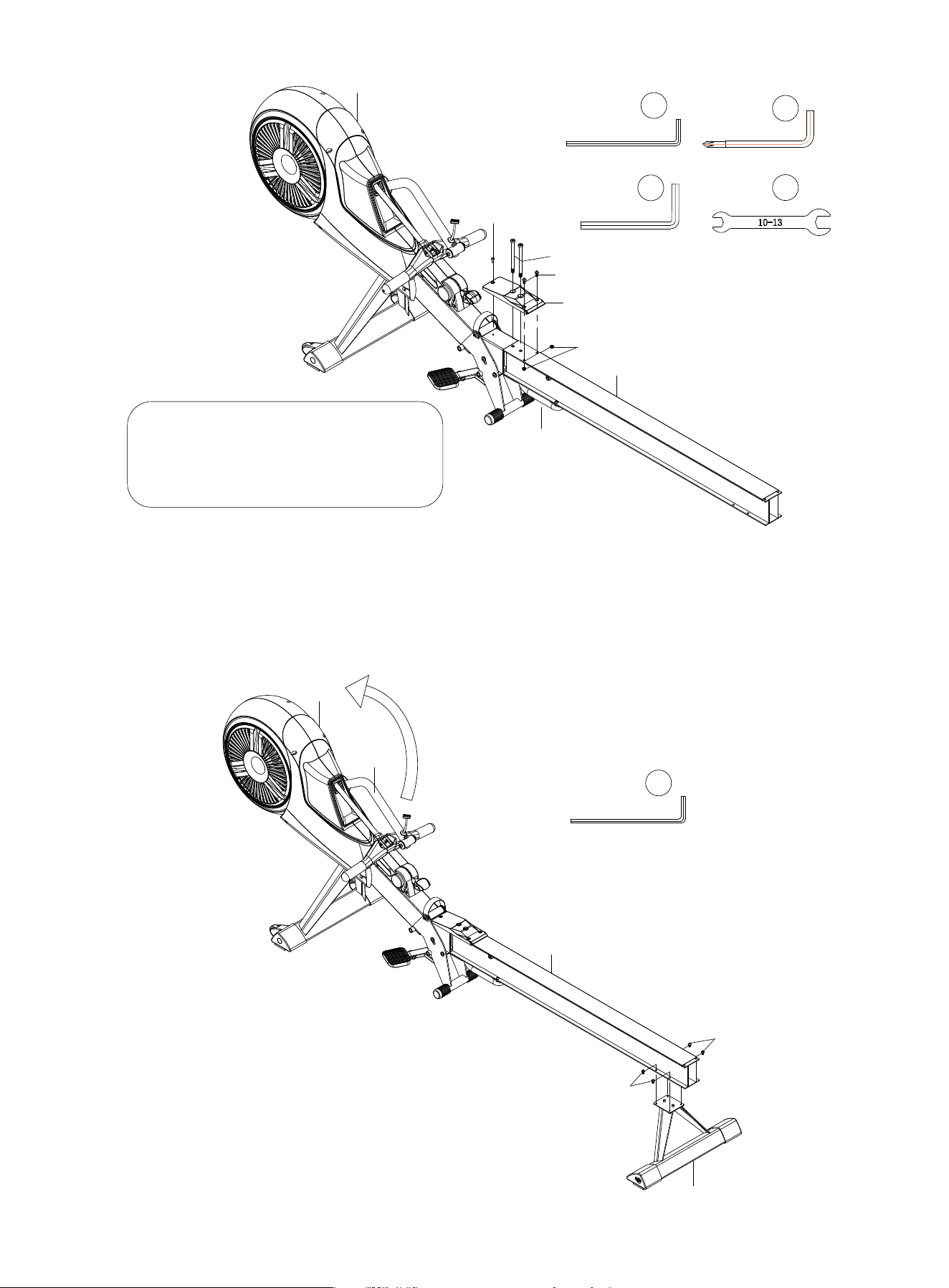
PASO 7
1. Instale el Tubo de Soporte Trasero (A4) en el Tubo de Riel de Aluminio (A2) y fíjelo con
4 Tornillos de Cabeza Redonda con Hexágono Interior (36).
2. Gire el Soporte de Pantalla (6) de vuelta a la posición adecuada.
A8
A7
A2
A1
31
32
29
33
41
8mm
1X
38
6mm
1X
39
A2
A11
A1
6
36
36
Una vez que la cubierta (A7) esté
bloqueada, apriete los tornillos instal-
ados en el paso 4.
34
4mm
1X
37
4mm
1X
37
PASO 8
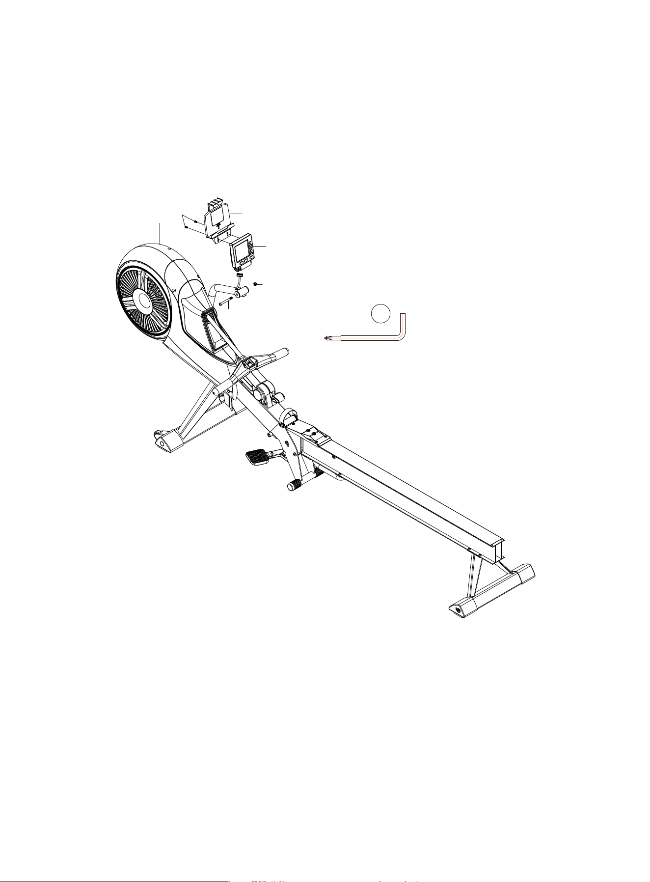
1. Instale la Pantalla (A6) en el Marco Principal (A1) y fíjelo con un Tornillo con Cabeza
Semicircular y hexágono interior (22) y una Tuerca de Nylon (25).
2. Conecte el cable de comunicación en el Marco Principal (A1) a la pantalla (A6).
3. Primero quite los dos Tornillos Phillips de Cabeza Plana Grande (26) en la parte poste-
rior de la Pantalla (A6). Luego instale el Soporte de Pantalla (A6-1) en la Pantalla (A6), y
use los dos Tornillos Phillips de Cabeza Plana Grande (26) ) para bloquear.
PASO 9
1. Instale el Cojín de Asiento Deslizante (A11) en el Tubo de Riel de Aluminio (A2).
2. Instale la Cubierta Embellecedora Trasera del Tubo del Riel (A12) en el tubo A2 y fíjelo
con dos Tornillos de Cabeza Redonda con Hexágono Interior (29) y Tuercas de Nylon
(33).
A1
A6-1
A6
26
25
22
6mm
1X
39
35
PASO 10
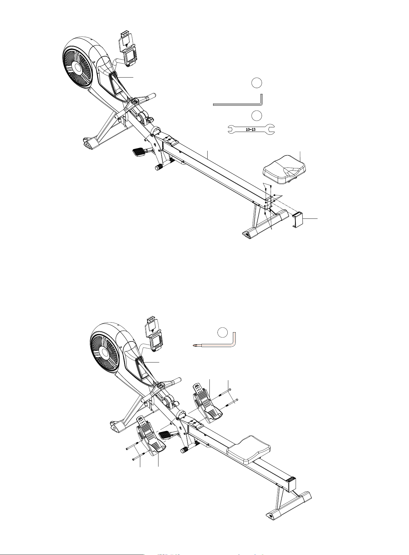
1.Instale el Pedal (A9) en el lado izquierdo del Marco Principal (A1) y fíjelo con dos Tornil-
los con Cabeza Cilíndrica y Hexágono Interior (28).
2.Instale el Pedal (A10) de la misma manera.
A1
A10
A9
28
28
6mm
1X
39
36
A12
A11
A1
A2
29
33
29
4mm
1X
37
41
INSTRUCCIONES DE PLEGADO
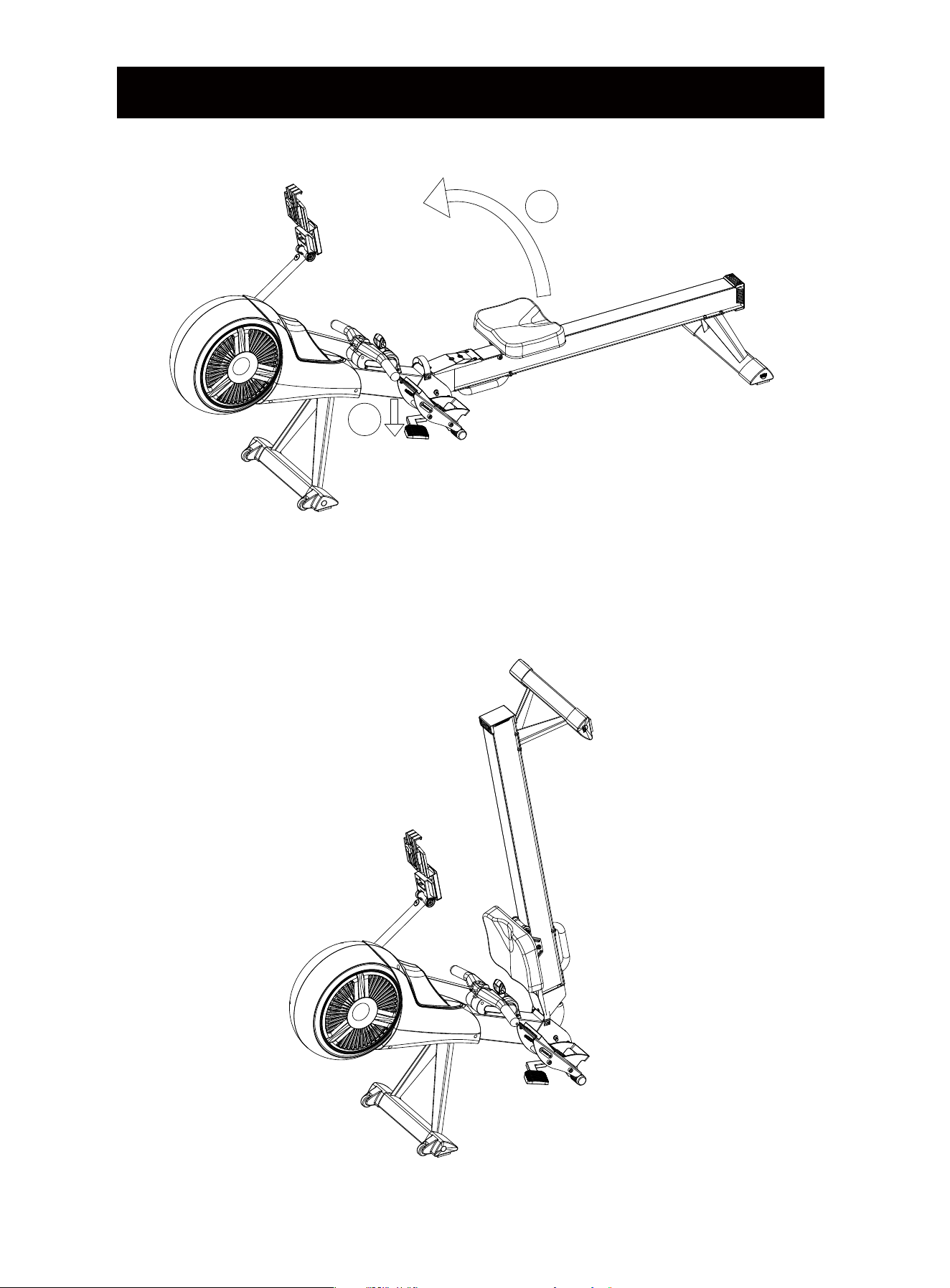
1. Empuje hacia abajo la Almohadilla de Liberación con el pie.
2. Levante el riel ligeramente.
NOTA: Mantenga el cuerpo alejado del riel cuando lo levante para evitar lastimarse.
2
1
37
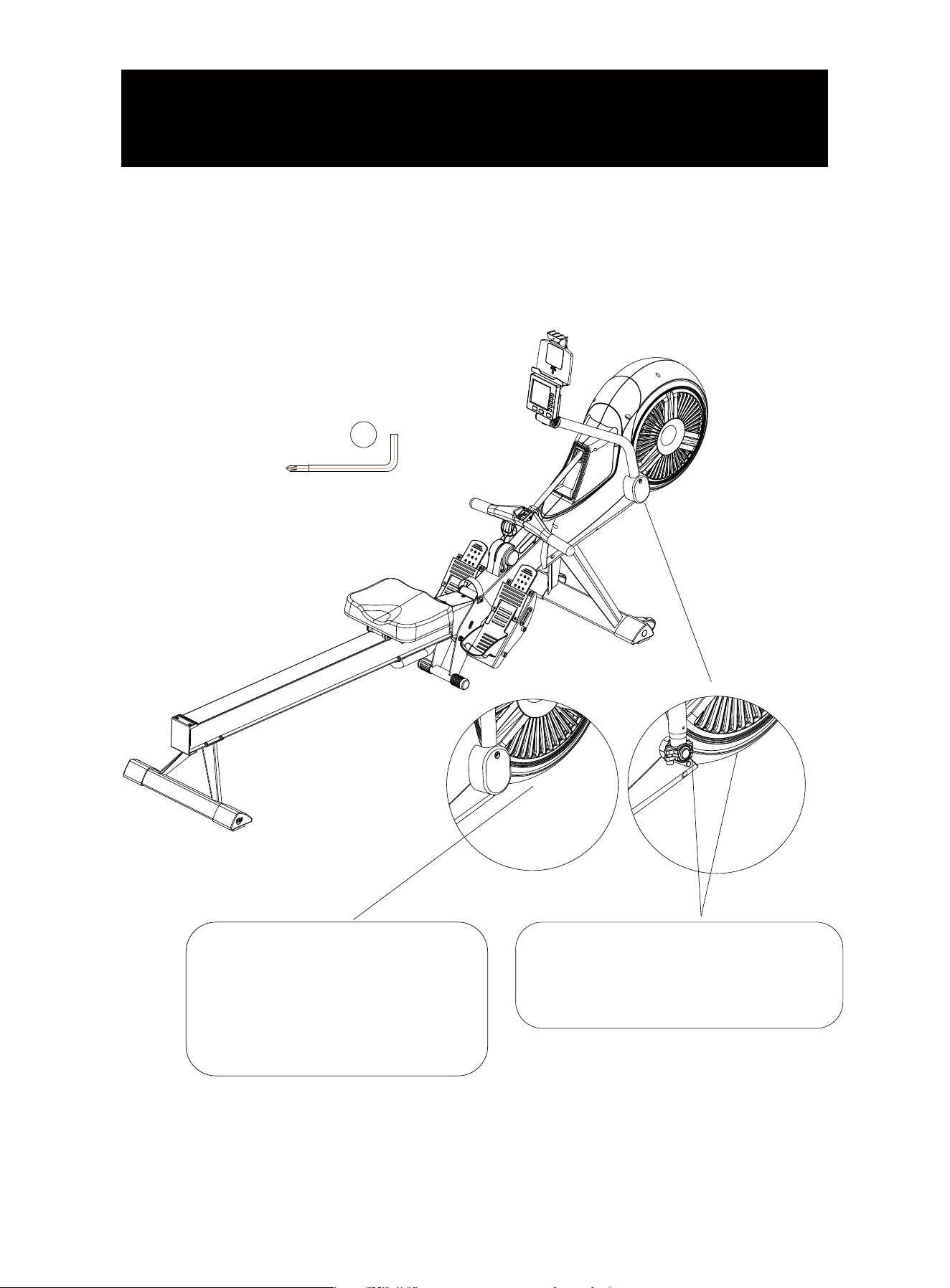
Si el tubo de soporte de la pantalla se afloja o se cae con facilidad cuando lo usa, quite la
cubierta debajo del tubo y use la Llave en L (39) para apretar los dos tornillos adentro.
6mm
1X
39
Utilice la llave en L con cruceta
para aflojar los tornillos de la cubi-
erta del tubo y luego retire la tapa.
Use una llave en L (6 mm) para apre-
tar un poco los dos tornillos hasta que
el tubo quede fijo.
38
MANTENIMIENTO DEL TUBO DE
SOPORTE DEL MONITOR
MANUAL DE FUNCIONAMIENTO DE LA PANTALLA
2.OPERACIÓN DE LA APLICACIÓN
1) Busque "KINOMAP" en la tienda de aplicaciones móviles para descargar la aplicación.
2) Una vez completada la descarga, abra la aplicación y registre su información personal,
encienda el Bluetooth de su teléfono móvil y asegúrese de que el monitor esté encendido
y despierto.
3) Añadir material deportivo, las operaciones específicas son las siguientes:
1. BLUETOOTH
Frecuencia de operación: este transmisor inalámbrico es un dispositivo Bluetooth 4.2. Su
frecuencia de operación es de 2.4GHZ.
2) Requisitos del sistema telefónico:
a.El sistema IOS no debe ser inferior a la versión 7.1, y debe ser compatible con Bluetooth
4.2, iPhone4S o una versión de teléfono móvil superior.
b.El sistema Android requiere la versión 4.3 o superior y debe ser compatible con Bluetooth
4.2.
3) Para garantizar la autenticidad y eficacia de la grabación de datos en el teléfono móvil, el
transmisor inalámbrico registra los datos del usuario y los envía a la aplicación móvil solo
cuando el monitor está conectado al teléfono móvil. Antes de usar el dispositivo, conecte la
aplicación al Bluetooth del monitor para garantizar la autenticidad de los datos registrados
en la aplicación móvil.
4) Cuando el monitor no haya recibido ninguna señal durante 2 minutos, entrará en modo
de suspensión. En el modo de suspensión, el teléfono móvil no podrá buscar pantallas.
Continúe usando el dispositivo o presione el botón para activar el monitor, el teléfono móvil
puede redescubrir y conectarse al monitor
5) Cuando el monitor se conecte con éxito a la aplicación, apagará la pantalla y todos los
datos se mostrarán en la aplicación.
6) Después de conectar la aplicación, si necesita usar el monitor nuevamente, debe salir de
la aplicación y apagar el Bluetooth del teléfono móvil.
39
4) Después de conectar el equipamento, elija la escena que desee y comience su entre-
namiento.
Gestión de equipamentos
Selecione“JOROTO” Selecione“MR60” Selecione el equipamento
Máquina de remar+
40
3.FUNCIONAMIENTO DE LA PANTALLA
Función de claves
Función del Monitor
ARTÍCULO
FUNCIÓN
MODE
ENTER
UP / Down
RESET
RECOVERY
Pulse este botón para cambiar entre las funciones de tiempo y tiempo/500m, pulso y RPM, distancia
y WATT, número de veces y número total de veces.
Presione el botón MODE para cambiar a la función que desea borrar, y luego presione el botón
RESET para borrar los valores (tiempo, veces, distancia, calorías y pulso ). Mantenga presionado el
botón RESET para reiniciar el monitor, y todos los valores será reiniciado a cero, excepto el total de
veces, que se restablecerá a cero después de volver a instalar la batería).
Presione este botón para probar la capacidad de recuperación de la frecuencia cardíaca del usuario
después del ejercicio. Después del entrenamiento, continúe usando el monitor de frecuencia cardía-
ca con correa para el pecho. Cuando el valor se muestre en el monitor, presione este botón para
iniciar la función de recuperación de la frecuencia cardíaca, El monitor ingresará a una cuenta
regresiva de 60 segundos y, una vez finalizada la cuenta regresiva, se mostrará en la pantalla el
estado de recuperación de la frecuencia cardíaca del usuario. El estado representado por el valor F
es el siguiente: (Presione la tecla RESET para volver a la pantalla principal).
Presione este botón para seleccionar las funciones de Tiempo , Veces, Distancia , Calorías y Pulso .
Presione este botón para configurar los valores objetivo de Tiempo , Veces, Distancia , Calorías y
Pulso.
Muestra el tiempo que el usuario ha hecho ejercicio.
Muestra el tiempo necesario para que el usuario haga ejercicio en 500 metros.
Muestra el número de veces de tirones.
Muestra la distancia que el usuario ha ejercitado .
Muestra la potencia que el usuario hace que produzca el entrenador.
Muestra el número de calorías quemadas por el usuario .
Muestra el número de veces que el usuario ha hecho ejercicio por minuto .
Muestre el valor de la frecuencia cardíaca del usuario (Use una correa de pecho de frecuencia
cardíaca Bluetooth antes de medir su frecuencia cardíaca; esta medición no se puede utilizar como
base médica).
Muestra el número de tirones acumulados del usuario para múltiples ejercicios, y el valor vuelve a
cero después de volver a instalar la batería.
1.0
1.0<F<2.0
2.0≤F≤2.9
3.0≤F≤3.9
4.0≤F≤5.9
6.0
Excelente
Normal _
bueno _
No tan bien
Malo
Pobre
Función de recuperación de latidos
TIME
TIME/500M
STROKES
TOTAL STROKES
DISTANCE
WATT
CALORIES
RPM
PULSE
41

CONFIGURACIÓN DEL VALOR OBJETIVO
Este monitor tiene cinco modos de entrenamiento objetivo: tiempo, veces, distancia,
calorías y pulso (Solo se pueden establecer en un estado sin movimiento).
1. Configuración del Objetivo de Tiempo :
Presione el botón "Mode" para cambiar a la función "Time".
Presione la tecla UP/DOWN para configurar el tiempo deseo (mantenga presionado el
botón UP/DOWN para acelerar la configuración). Cuando se alcance el tiempo deseado,
detenga el botón. Luego comience a usar la máquina y la pantalla comenzará la cuenta
regresiva.
Cuando la cuenta llega a 0, la pantalla emitirá tres pitidos para recordar al usuario que se ha
alcanzado el objetivo de entrenamiento.
Si continúa entrenando en este punto, el monitor automáticamente comenzará a contar
desde 0 .
2. Configuración del Objetivo de Veces:
Pulse la tecla "Mode" para cambiar a la función "STROKES".
Presione la tecla UP/DOWN para configurar las veces deseas (mantenga presionado la
tecla UP/DOWN para acelerar la configuración). Cuando alcance el objeto deseado, deten-
ga el botón. Luego, comience a usar la máquina y la pantalla comenzará a cuenta regresiva.
Cuando la cuenta llega a 0, la pantalla emitirá tres pitidos para recordar al usuario que se ha
alcanzado el objetivo de entrenamiento.
Si continúa entrenando en este punto, el monitor automáticamente comenzará a contar
desde 0.
3. Configuración del Objetivo de Distancia:
Presione el botón "Mode" para cambiar a la función " Distance".
Presione la tecla UP/DOWN para configurar el valor objetivo (mantenga presionado el botón
UP/DOWN para acelerar la configuración). Cuando alcance la distancia deseada , detenga
el botón. Luego comience a usar la máquina y la pantalla comenzará la cuenta regresiva.
Cuando la cuenta llega a 0, la pantalla emitirá tres pitidos para recordar al usuario que se ha
alcanzado el objetivo de entrenamiento.
Si continúa entrenando en este punto, el monitor automáticamente comenzará a contar
desde 0 .
4. Configuración del Objetivo de Calorías
Presione el botón "Mode" para cambiar a la función " Calories".
Presione la tecla UP/DOWN para establecer las calorías deseadas (mantenga presionado
el botón UP/DOWN para acelerar la configuración). Cuando alcance el valor deseado ,
detenga el botón. Luego comience a usar la máquina y la pantalla comenzará la cuenta
regresiva.
42
Cuando la cuenta llega a 0, la pantalla emitirá tres pitidos para recordar al usuario que se ha
alcanzado el objetivo de entrenamiento.
Si continúa entrenando en este punto, el monitor automáticamente comenzará a contar
desde 0 .
5. Configuración del objetivo de Pulso
Presione el botón "Mode" para cambiar a la función "Pulse".
Presione la tecla UP/DOWN para establecer el objetivo del pulso ((mantenga presionado el
botón UP/DOWN para acelerar la configuración). Cuando alcance el valor deseado, deten-
ga el botón. Y comience a usar la máquina.
Cuando el latido del corazón del usuario es más alto que el objetivo, el monitor emitirá tres
pitidos para recordar al usuario.
Durante el proceso de configuración, si desea modificar los datos de destino, puede
presionar el botón RESET para borrar la configuración actual, o presione prolongadamente
el botón RESET para borrar todas las configuraciones y luego siga las instrucciones anteri-
ores para restablecer.
NOTA
Si el monitor se atenúa o no se muestran datos, reemplace la batería.
Si no hay entrada de señal o no se presiona durante 2 minutos, la pantalla se apagará
automáticamente y el monitor pasará al modo de suspensión.
Cuando comience a entrenar o presione cualquiera tecla, el monitor se reiniciará y funciona-
rá.
Cuando comience a entrenar, el monitor comenzará a contar automáticamente. Cuando
deje de hacer ejercicio durante más de 4 segundos, el monitor dejará de contar.
Tiempo
Tiempo / 500m
Veces
Veces total
Distancia
Vatio
Calorías
RPM
Latido del corazón
0:00~99:59
0:00~99:59
0~99999
0~99999
0~9999 m
0~ 385W
0~ 9999cal
0~999 / minuto
60~240 BPM
Batería n° 1 (tipo de D) * 2
0°C ~ +40°C
-10°C ~ +60°C
Modelo de Batería
Temperatura de Trabajo
Temperatura de Almacenamiento
Funciones
Parámetro del Monitor
43
Email:[email protected]
Tel: 1-888-828-2521 86-400-700-5199
Scan the Instagram QR Code to reach us online
Li’ang Health Science and Technology (Beijing) Co.,Ltd

