Manufactured by:
Importer for UK:
Importer for EU:
Authorized Representative in EU:
Fabricado por:
Importador:
Representante Autorizado para la UE:
Fabriqué par :
Importateur :
Représentant autorisé dans l’UE :
Hergestellt von:
Importeur:
Vertretungsberechtigter in der EU:
Fabbricato da:
Importatore:
Rappresentante autorizzato nell’UE:
Panasonic Entertainment & Communication Co., Ltd.
1-10-12, Yagumo-higashi-machi, Moriguchi City, Osaka, Japan
Panasonic UK, a branch of Panasonic Marketing Europe GmbH
Maxis 2, Western Road, Bracknell, Berkshire, RG12 1RT
Panasonic Marketing Europe GmbH
Hagenauer Strasse 43, 65203 Wiesbaden, Germany
Panasonic Marketing Europe GmbH
Panasonic Testing Centre, Winsbergring 15, 22525 Hamburg, Germany
Panasonic Entertainment & Communication Co., Ltd.
1-10-12, Yagumo-higashi-machi, Ciudad de Moriguchi, Osaka, Japón
Panasonic Marketing Europe GmbH
Hagenauer Strasse 43, 65203 Wiesbaden, Alemania
Panasonic Marketing Europe GmbH
Panasonic Testing Centre, Winsbergring 15, 22525 Hamburgo, Alemania
Panasonic Entertainment & Communication Co., Ltd.
1-10-12, Yagumo-higashi-machi, ville de Moriguchi, Osaka, Japon
Panasonic Marketing Europe GmbH
Hagenauer Strasse 43, 65203 Wiesbaden, Allemagne
Panasonic Marketing Europe GmbH
Panasonic Testing Centre, Winsbergring 15, 22525 Hambourg, Allemagne
Panasonic Entertainment & Communication Co., Ltd.
1-10-12, Yagumo-higashi-machi, Moriguchi City, Osaka, Japan
Panasonic Marketing Europe GmbH
Hagenauer Strasse 43, 65203 Wiesbaden, Deutschland
Panasonic Marketing Europe GmbH
Panasonic Testing Centre, Winsbergring 15, 22525 Hamburg, Deutschland
Panasonic Entertainment & Communication Co., Ltd.
1-10-12, Yagumo-higashi-machi, Città di Moriguchi, Osaka, Giappone
Panasonic Marketing Europe GmbH
Hagenauer Strasse 43, 65203 Wiesbaden, Germania
Panasonic Marketing Europe GmbH
Panasonic Testing Centre, Winsbergring 15, 22525 Amburgo, Germania
Operating Instructions /
Instrucciones de funcionamiento /
Mode d’emploi / Bedienungsanleitung /
Istruzioni d’uso / Інструкція з експлуатації
Handle unit / Unidad del asa / Poignée /
XLR Handgriff / Maniglia / Блок ручки
Model No. / Modelo N. / Modèle N° / Modell-Nr. / Modello N. / Модель №
VW-HU1
A B C
1AC1R25SXZ
1PP1R25SXZ
15 1214 13
118 10
16
9
6 5
7
1 2
3
4
26 25 24
2120 22 23
17
19
18
12 3 4 5
A B C
1AC1R25SXZ
1PP1R25SXZ
15 1214 13
118 10
16
9
6 5
7
1 2
3
4
26 25 24
2120 22 23
17
19
18
12 3 4 5
DVQX2756ZA
F0325MZ0
Thank you for purchasing this Panasonic product.
≥ Please read these instructions carefully before using
this product, and save this manual for future use.
≥
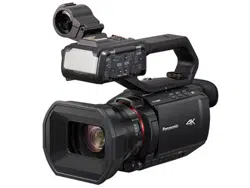
The following functions can be used when this product is
attached to a 4K Video Camera HC-X1500/HC-X1600:
j
Using audio equipment/external microphone (XLR, 3-pin)
j Built-in LED light
j REC button (on the handle)
j Zoom lever (on the handle)
j Tally lamp
≥ HC-X1500 is used in the camera illustrations.
≥
For details about the above functions and the operation of
the handle unit, refer to the operating instructions for the
4K Video Camera.
≥
The 4K Video Camera is not supplied.
≥
Be aware that Panasonic accepts no responsibility for any
incidents, damage, or malfunctions occurring due to dropping
of this product or the camera while using this product.
≥
When requesting a repair for the handle unit, request a repair
for the video camera as well, as the cause of the problem may
be in the video camera.
≥
The external design and specifications of this product, as
described in this document, may differ from the actual product.
≥
Illustrations used in this document may differ from the actual
product and the actual images displayed on the product.
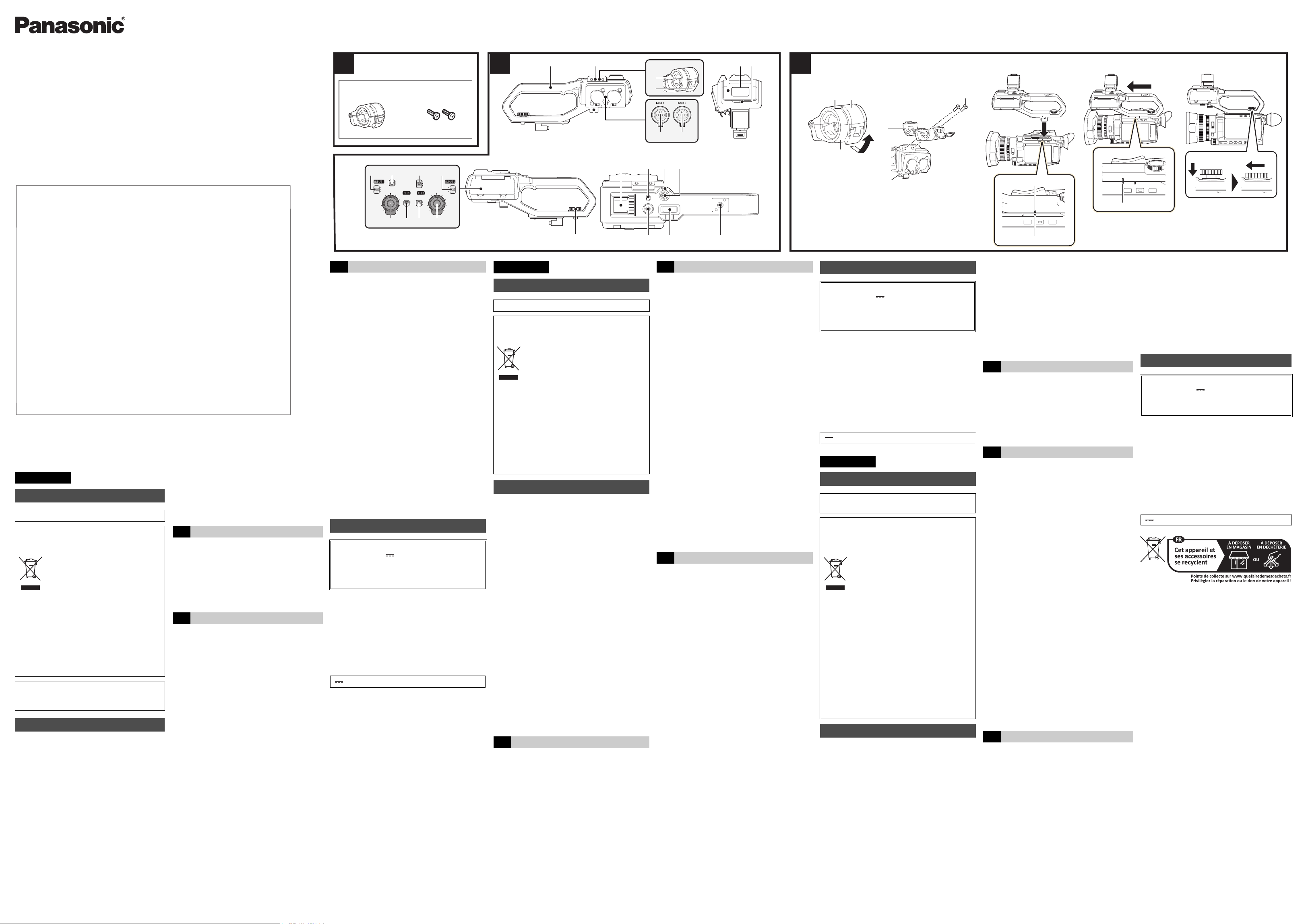
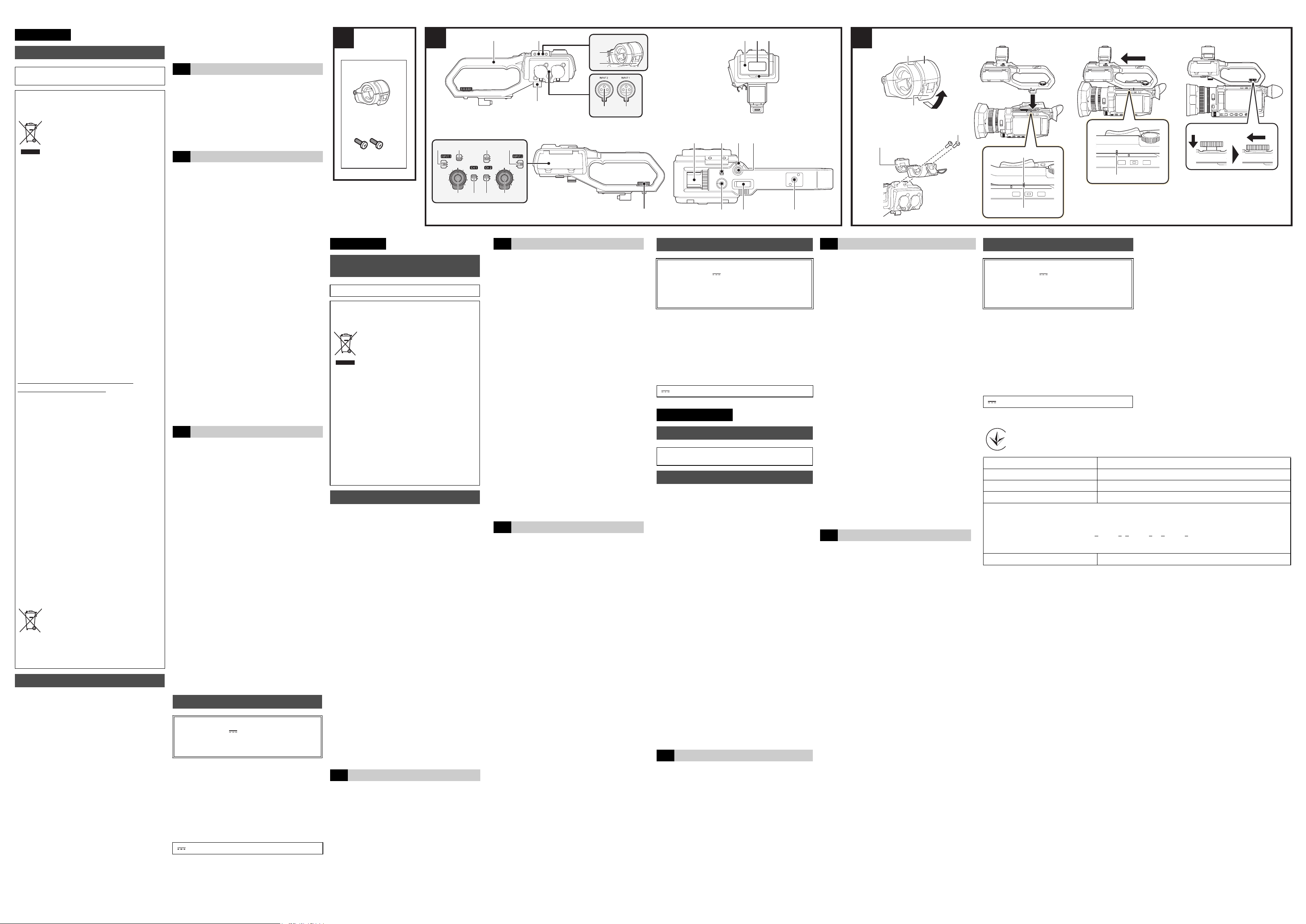
Check the accessories before using this unit.
A Microphone holder
≥ The microphone holder mounting screws are
supplied with the microphone holder.
B Microphone holder mounting screws
≥ Length 12 mm (×2)
≥ Keep the microphone holder mounting screws out of
reach of children to prevent swallowing.
1
Handle
2
Microphone holder mounting section
3
Microphone holder (C With a microphone
holder attached)
4
Buckle (
C
With a microphone holder attached)
5
<INPUT 1> terminal (XLR, 3-pin)
6
<INPUT 2> terminal (XLR, 3-pin)
7
Microphone cable clamp
8
<INPUT1> switch
9
CH1 SELECT switch
10
CH2 SELECT switch
11
<INPUT2> switch
12
<AUDIO LEVEL CH2> dial
13
<CH2> switch
14
<CH1> switch
15
<AUDIO LEVEL CH1> dial
16
Handle unit mounting screw
17
Light cover
≥ Keep the light cover out of reach of children to
prevent swallowing.
18
Built-in LED light
19
Tally lamp
20
Accessory shoe (on the handle)
21
<LIGHT> switch
22
Hold lever
23
REC button (on the handle)
24
Accessory mounting hole
25
Zoom lever (on the handle)
26
Light dimmer dial
ENGLISH
Information for Your Safety
This unit is intended for use in moderate climates.
Disposal of Old Equipment
Only for European Union and countries
with recycling systems
This symbol on the products, packaging,
and/or accompanying documents means that
used electrical and electronic products must
not be mixed with general household waste.
For proper treatment, recovery and recycling
of old products, please take them to applicable collection
points in accordance with your national legislation.
By disposing of them correctly, you will help to save valu-
able resources and prevent any potential negative effects
on human health and the environment.
For more information about collection and recycling,
please contact your local authority.
Penalties may be applicable for incorrect disposal of this
waste, in accordance with national legislation.
For Turkey
AEEE Yönetmeliğine Uygundur.
AEEE Complies with Directive of Turkey.
Precautions
A
Accessories
B
Names of the components
¥
Attach while the power of the camera is turned off.
1 Open the microphone holder.
Open buckle D, and detach fitting E from hook F.
2 Attach the microphone holder to the
microphone holder mounting section on
the handle unit.
G Microphone holder mounting screws
H Microphone holder
≥
Attach using a commercially-available screwdriver.
≥
There will be some rubbing noises with the rubber when
screwing in the microphone holder mounting screws, but
please ensure they are done up tightly.
3 Push the handle unit into the handle unit
mounting section on the camera.
Match the positions of mounting mark I on the
handle unit and mounting mark J on the camera
when pushing in.
4 Slide the handle unit in the direction
indicated by the arrow.
Slide up to mounting mark
K
.
5 While pressing the handle unit mounting
screw down, turn it in the direction
indicated by arrow 2 until it stops.
∫ How to remove
Remove by doing the steps for attaching in reverse.
External dimensions (W×H×D):
Approx. 71 mm ×89 mm ×207 mm
(including protrusions, excluding microphone holder)
Mass:
Approx. 305 g
(main part of the handle unit only, excluding microphone holder
and microphone holder mounting screws)
The symbols on this product (including the accessories)
represent the following:
Gracias por comprar este producto Panasonic.
≥
Lea cuidadosamente estas instrucciones antes de usar este
producto, y guarde este manual para usarlo en el futuro.
≥
Las siguientes funciones se pueden utilizar cuando este
producto está acoplado a una cámara de video 4K
HC-X1500/HC-X1600:
j Uso del equipo de audio/micrófono externo
(XLR, 3 pines)
j Luz LED integrada
j Botón REC (en el mango)
j Palanca del zoom (en el mango)
j Luz indicadora
≥
Para las ilustraciones de la cámara se utiliza el modelo
HC-X1500.
≥
Para obtener más información sobre las funciones anteriores y
el funcionamiento de la unidad de mango, consulte el manual de
instrucciones de la cámara de vídeo 4K.
≥
La cámara de vídeo 4K no se suministra.
≥
Tenga en cuenta que Panasonic no acepta ninguna
responsabilidad por cualquier incidente, daño o mal
funcionamiento que ocurra debido a la caída de este
producto o de la cámara mientras se utiliza este producto.
≥
Cuando solicite una reparación para la unidad del asa,
solicite también una reparación para la videocámara, ya que
la causa del problema podría estar en la videocámara.
≥
El diseño exterior y las especificaciones de este producto, tal y
como se describen en este documento, podrían diferir del
producto real.
≥
Las ilustraciones utilizadas en este documento podrían diferir del
producto real y las imágenes reales mostradas en el producto.
Revise los accesorios antes de usar este dispositivo.
A Soporte del micrófono
≥ Con el soporte del micrófono, se suministran los
tornillos de instalación del soporte del micrófono.
B Tornillos de instalación del soporte del micrófono
≥
Longitud 12 mm (×2)
≥ Mantenga los tornillos de instalación del soporte del
micrófono fuera del alcance de los niños para evitar
que se los traguen.
C
Attaching the handle unit
Specifications
Input voltage:
23.6 V/5 V/3.15 V
Power consumption:
Maximum approx. 3.1 W (when connected to the
camera)
DC
ESPAÑOL
Información para su seguridad
Esta unidad está destinada para usar en climas moderados.
Eliminación de Aparatos Viejos
Solamente para la Unión Europea y países con
sistemas de reciclado.
Este símbolo en los productos, su embalaje o
en los documentos que los acompañen signi-
fica que los productos eléctricos y electrónicos
usadas no deben mezclarse con los residuos
domésticos.
Para el adecuado tratamiento, recuperación y reciclaje de
los productos viejos llévelos a los puntos de recogida de
acuerdo con su legislación nacional.
Si los elimina correctamente ayudará a preservar valiosos
recursos y evitará potenciales efectos negativos sobre la
salud de las personas y sobre el medio ambiente.
Para más información sobre la recogida u reciclaje, por
favor contacte con su ayuntamiento.
Puede haber sanciones por una incorrecta eliminación de
este residuo, de acuerdo con la legislación nacional.
Precauciones
A
Accesorios
1
Mango
2
Sección de montaje del soporte del
micrófono
3
Soporte del micrófono (C Con un soporte
del micrófono montado)
4
Hebilla (C Con un soporte del micrófono
montado)
5
Terminal <INPUT 1> (XLR, 3 pines)
6
Terminal <INPUT 2> (XLR, 3 pines)
7
Abrazadera de cable del micrófono
8
Conmutador <INPUT1>
9
Conmutador CH1 SELECT
10
Conmutador CH2 SELECT
11
Conmutador <INPUT2>
12
Dial <AUDIO LEVEL CH2>
13
Conmutador <CH2>
14
Conmutador <CH1>
15
Dial <AUDIO LEVEL CH1>
16
Tornillo de montaje de la unidad de mango
17
Tapa de luz
≥ Guarde la tapa de luz fuera del alcance de los
niños para evitar que se la traguen.
18
Luz LED integrada
19
Luz indicadora
20
Zapata adicional (en el mango)
21
Conmutador <LIGHT>
22
Palanca de sujeción
23
Botón REC (en el mango)
24
Orificio de montaje de accesorios
25
Palanca del zoom (en el mango)
26
Dial de regulación de la luz
¥ Acoplar mientras la cámara esté apagada.
1 Abra el soporte del micrófono.
Abra la hebilla D y separe el racor E del gancho F.
2 Conecte el soporte del micrófono a la
sección de montaje del soporte del
micrófono de la unidad de mango.
G Tornillos de instalación del soporte del micrófono
H Soporte del micrófono
≥
Móntelo usando un destornillador disponible en tiendas.
≥
Al atornillar los tornillos de instalación del soporte del
micrófono se producirán algunos ruidos de roce con la
goma, pero asegúrese de que estén bien apretados.
3
Inserte la unidad de mango en la sección de
montaje de la unidad de mango de la cámara.
Haga coincidir la marca de montaje
I
de la unidad de
mango con la marca de montaje
J
de la cámara cuando
la introduzca.
4 Deslice la unidad de mango en la dirección
indicada por la flecha.
Deslice hacia arriba hasta la marca de montaje K.
5
Mientras presiona el tornillo de montaje de la
unidad de mango, gírelo en la dirección
indicada por la flecha
2
hasta que se detenga.
∫ Cómo desmontarla
Desmonte siguiendo los pasos para el montaje a la inversa.
Dimensiones (W×H×D):
Aprox. 71 mm× 89 mm× 207 mm
(incluyendo los salientes y excluyendo el soporte del
micrófono)
Masa:
Aprox. 305 ]
(solo la parte principal de la unidad de mango,
excluyendo el soporte del micrófono y los tornillos de
instalación del soporte del micrófono)
Los símbolos en este producto (incluidos los accesorios)
representan lo siguiente:
Merci d’avoir acheté ce produit Panasonic.
≥
Il est recommandé de lire attentivement ce manuel avant
d’utiliser l’appareil et de le conserver pour consultation
ultérieure.
≥
Les fonctions suivantes peuvent être utilisées lorsque ce
produit est installé sur une caméra vidéo 4K HC-X1500/
HC-X1600 :
j
Utilisation d’un équipement audio/microphone externe
(XLR, 3 broches)
j
Éclairage LED intégré
j
Touche REC (sur la poignée)
j
Levier de zoom (sur la poignée)
j
Voyant de Tally
≥
Le modèle HC-X1500 est utilisé pour les illustrations de la
caméra.
≥
Pour avoir des détails sur les fonctions ci-dessus et sur le
fonctionnement de la poignée, consulter le mode d’emploi de
la caméra vidéo 4K.
≥
La caméra vidéo 4K n’est pas fournie.
B
Descripción de las piezas
C
Montaje de la unidad de mango
Especificaciones
Tensión de entrada:
23,6 V/5 V/3,15 V
Consumo de energía:
Máximo aprox. 3,1 W (cuando está conectada a la
cámara)
CC
FRANÇAIS
Précautions à prendre
Cet appareil est conçu pour une utilisation dans des
climats tempérés.
Élimination des équipements usagés
Applicable uniquement dans les pays membres
de l’Union européenne et les pays disposant de
systèmes de recyclage.
Apposé sur le produit lui-même, sur son
emballage, ou figurant dans la documentation
qui l’accompagne, ce pictogramme indique que
les appareils électriques et électroniques
usagés doivent être séparés des ordures
ménagères.
Afin de permettre le traitement, la valorisation et le
recyclage adéquats des appareils usagés, veuillez les
porter à l’un des points de collecte prévus, conformément à
la législation nationale en vigueur.
En les éliminant conformément à la réglementation en
vigueur, vous contribuez à éviter le gaspillage de
ressources précieuses ainsi qu’à protéger la santé humaine
et l’environnement.
Pour de plus amples renseignements sur la collecte et le
recyclage, veuillez vous renseigner auprès des collectivités
locales.
Le non-respect de la réglementation relative à l’élimination
des déchets est passible d’une peine d’amende.
Précautions
≥
Il faut savoir que Panasonic n’assume aucune
responsabilité pour tout incident, dommage ou
dysfonctionnement résultant de la chute de ce produit ou
de la caméra vidéo.
≥
En demandant une réparation de l’unité poignée, penser à
en faire également une pour le caméscope, car le
problème pourrait venir de ce dernier.
≥
La conception externe et les spécifications de ce produit,
comme décrits dans ce document, peuvent être différentes du
véritable produit.
≥
Les illustrations utilisées dans ce document peuvent être
différentes du véritable produit et des véritables images
affichées sur le produit.
Vérifier les accessoires avant d’utiliser cet appareil.
A Support du microphone
≥ Les vis de montage du support du microphone
sont fournies avec le support du microphone.
B Vis de montage du support du microphone
≥ Longueur 12 mm (×2)
≥
Conserver les vis de montage du support du microphone
hors de portée des enfants pour éviter qu’ils les avalent.
1
Poignée
2
Position de montage du support du microphone
3
Support du microphone (C Avec un
support du microphone installé)
4
Boucle (C Avec un support du microphone
installé)
5
Prise <INPUT 1> (XLR, 3 broches)
6
Prise <INPUT 2> (XLR, 3 broches)
7
Collier de câble du microphone
8
Interrupteur <INPUT1>
9
Interrupteur CH1 SELECT
10
Interrupteur CH2 SELECT
11
Interrupteur <INPUT2>
12
Molette <AUDIO LEVEL CH2>
13
Interrupteur <CH2>
14
Interrupteur <CH1>
15
Molette <AUDIO LEVEL CH1>
16
Vis de montage de la Poignée
17
Cache de l’éclairage
≥
Conserver le cache de l’éclairage hors de portée
des enfants pour éviter qu’ils les avalent.
18
Éclairage LED intégré
19
Voyant de Tally
20
Porte-accessoire (sur la poignée)
21
Interrupteur <LIGHT>
22
Levier de maintien
23
Touche REC (sur la poignée)
24
Orifice de montage des accessoires
25
Levier de zoom (sur la poignée)
26
Molette du variateur de lumière
¥
Installer pendant que la caméra vidéo est hors tension.
1 Ouvrir le support du microphone.
Ouvrir la boucle
D
et détacher le pièce
E
du crochet
F
.
2
Fixer le support du microphone à la position
de montage dédiée à celui-ci sur la Poignée.
G Vis de montage du support du microphone
H Support du microphone
≥
Fixer en utilisant un tournevis disponible dans le commerce.
≥
Il pourrait y avoir des bruits de frottement avec le
caoutchouc en vissant les vis de montage du support du
microphone, mais veiller à ce qu’elles soient bien serrées.
3 Pousser la Poignée dans la position de
montage de la Poignée du caméscope.
Faire correspondre le repère de montage
I
de la Poignée
et le repère de montage
J
du caméscope en la poussant.
4 Faire glisser la Poignée dans le sens
indiqué par la flèche.
Faire glisser jusqu’au repère de montage K.
5 Tout en appuyant sur la vis de montage
de la Poignée, la tourner dans le sens de
la flèche 2 jusqu’à ce qu’elle s’arrête.
∫ Comment la retirer
Retirer en effectuant les étapes de la mise en place
dans le sens inverse.
Dimensions (L×H×P) :
Environ 71 mm× 89 mm× 207 mm
(parties saillantes comprises, support du microphone
non compris)
Poids :
Environ 305 ]
(partie principale de la poignée uniquement, support
du microphone et vis de montage du support du
microphone non compris)
Les symboles présents sur ce produit (y compris sur les
accessoires) indiquent ce qui suit :
A
Accessoires
B
Description des éléments
C
Mise en place de la Poignée
Caractéristiques
Tension d’entrée :
23,6 V/5 V/3,15 V
Consommation électrique :
Environ 3,1 W maximum (lorsque branché au caméscope)
CC
Panasonic Entertainment & Communication Co., Ltd.
Web Site: http://www.panasonic.com
C Panasonic Entertainment & Communication Co., Ltd. 2025
VW-HU1_E_DVQX2756ZA_250219.fm 1 ページ 2025年3月12日 水曜日 午前10時5分
A B C
1AC1R25SXZ
1PP1R25SXZ
15 1214 13
118 10
16
9
6 5
7
1 2
3
4
26 25 24
2120 22 23
17
19
18
1
2
345
Vielen Dank, dass Sie sich für ein Panasonic Produkt entschieden haben.
≥
Bitte lesen Sie diese Anleitung vor der Inbetriebnahme dieses
Produkts aufmerksam durch, und bewahren Sie dieses Handbuch
für spätere Bezugnahme griffbereit auf.
≥
Die folgenden Funktionen können genutzt werden, wenn dieses
Produkt an einen 4K Camcorder HC-X1500/HC-X1600
angeschlossen ist:
j
Verwendung eines Audiogeräts/externen Mikrofons (XLR, 3-
polig)
j
Integrierte LED-Leuchte
j
REC-Taste (auf Haltegriff)
j
Zoomhebel (auf Haltegriff)
j
Tally-Lampe
≥
In den Abbildungen wird das Modell HC-X1500 gezeigt.
≥
Einzelheiten zu den obigen Funktionen und zur Bedienung des
XLR-Handgriffs finden Sie in der Bedienungsanleitung des 4K-
Camcorders.
≥
Der 4K-Camcorder befindet sich nicht im Lieferumfang.
≥
Beachten Sie, dass Panasonic keine Haftung für Vorfälle,
Schäden oder Funktionsstörungen übernimmt, die durch das
Herunterfallen dieses Produkts oder der Kamera während der
Verwendung dieses Produkts entstehen.
≥
Wenn Sie eine Reparatur für den XLR-Handgriff anfordern,
fordern Sie auch eine Reparatur für die Videokamera an, da die
Ursache des Problems in der Videokamera liegen kann.
≥
Die in diesem Dokument beschriebenen Erscheinungsmerkmale
und technischen Daten des Produkts können sich vom
tatsächlichen Produkt unterscheiden.
≥
Abbildungen in diesem Dokument können sich vom tatsächlichen
Produkt und den darauf angezeigten Informationen unterscheiden.
Kontrollieren Sie vor dem Gebrauch dieses Geräts das Zubehör.
A Mikrofonhalterung
≥ Die Mikrofonhalter-Befestigungsschrauben
liegen der Mikrofonhalterung bei.
B Mikrofonhalter-Befestigungsschrauben
≥ Länge 12 mm (×2)
≥
Bewahren Sie die Mikrofonhalter-Befestigungsschrauben für
Kinder unzugänglich auf, um ein Verschlucken zu verhindern.
1
Haltegriff
2
Mikrofonhalterungsaufnahme
3
Mikrofonhalterung (C Mit montierter
Mikrofonhalterung)
4
Schnalle (
C
Mit montierter Mikrofonhalterung)
5
<INPUT 1>-Anschluss (XLR, 3-polig)
6
<INPUT 2>-Anschluss (XLR, 3-polig)
7
Mikrofonkabelanschluss
8
<INPUT1>-Schalter
9
CH1 SELECT-Schalter
10
CH2 SELECT-Schalter
11
<INPUT2>-Schalter
12
<AUDIO LEVEL CH2>-Einstellrad
13
<CH2>-Schalter
14
<CH1>-Schalter
15
<AUDIO LEVEL CH1>-Einstellrad
16
Haltegriffeinheit-Befestigungsschraube
17
Leuchtenabdeckung
≥
Bewahren Sie die Leuchtenabdeckung für Kinder
unzugänglich auf, um ein Verschlucken zu verhindern.
18
Integrierte LED-Leuchte
19
Tally-Lampe
20
Zubehörschuh (auf Haltegriff)
21
<LIGHT>-Schalter
22
Hold-Hebel
23
REC-Taste (auf Haltegriff)
24
Montageloch für Zubehör
25
Zoomhebel (auf Haltegriff)
26
Leuchtendimmer-Einstellrad
¥ Bei ausgeschalteter Kamera anbringen.
1 Öffnen Sie die Mikrofonhalterung.
Öffnen Sie die Schnalle
D
und lösen Sie die Fassung
E
vom Haken
F
.
2
Befestigen Sie die Mikrofonhalterung an der
Mikrofonhalterungsaufnahme der Haltegriffeinheit.
G Mikrofonhalter-Befestigungsschrauben
H Mikrofonhalterung
≥ Verwenden Sie zum Befestigen einen
handelsüblichen Schraubendreher.
≥
Beim Eindrehen der Mikrofonhalter-
Befestigungsschrauben kommt es durch den Gummi
zu Reibungsgeräuschen. Achten Sie bitte trotzdem
darauf, dass die Schrauben fest angezogen werden.
3
Schieben Sie den XLR-Handgriff in die
XLRHandgriffaufnahme auf der Kamera.
Richten Sie beim Hineinschieben die
Montagemarkierung
I
am XLR-Handgriff und die
Montagemarkierung
J
an der Kamera aufeinander aus.
4
Schieben Sie den XLR-Handgriff in Pfeilrichtung.
Schieben Sie ihn bis zur Montagemarkierung
K
hinein.
5
Drücken Sie die Befestigungsschraube der
Haltegriffeinheit nach unten und ziehen Sie
sie in Pfeilrichtung
2
bis zum Anschlag fest.
∫ Abnehmen
Führen Sie die Schritte zum Anbringen in umgekehrter
Reihenfolge aus.
Außenmaße (B×H× T):
Ca. 71 mm× 89 mm× 207 mm (einschließlich
vorstehender Teile, ausschließlich Mikrofonhalterung)
Gewicht:
Ca. 305 ] (nur Hauptteil des XLR-Handgriffs, ohne
Mikrofonhalterung und Mikrofonhalter-
Befestigungsschrauben)
Die Symbole an diesem Produkt (einschließlich
Zubehör) haben die folgenden Bedeutungen:
DEUTSCH
Sicherheitshinweise
Dieses Gerät ist für den Betrieb in Ländern mit
gemäßigtem Klima bestimmt.
Entsorgung von Altgeräten und Batterien
Nur für die Europäische Union und Länder
mit Recyclingsystemen
Dieses Symbol auf den Produkten, der
Verpackung und/oder den
Begleitdokumenten bedeutet, dass
gebrauchte elektrische und elektronische
Produkte sowie Batterien nicht in den
allgemeinen Hausmüll gegeben werden dürfen.
Bitte führen Sie alte Produkte und verbrauchte
Batterien zur Behandlung, Aufarbeitung bzw. zum
Recycling gemäß den gesetzlichen Bestimmungen
den zuständigen Sammelpunkten zu.
Zusätzlich ist die Rückgabe unter bestimmten
Voraussetzungen auch bei Vertreibern
(Verkaufsfläche für Elektro- und Elektronikgeräte von
mindestens 400 m² und Lebensmitteleinzelhändler,
die über eine Gesamtverkaufsfläche von mindestens
800 m² verfügen und mehrmals im Kalenderjahr oder
dauerhaft auch Elektro- und Elektronikgeräte
anbieten und auf dem Markt bereitstellen) möglich.
Die Rücknahme hat kostenlos beim Kauf eines
gleichartigen Neugerätes zu erfolgen (1:1
Rücknahme). Unabhängig davon, gibt es die
Möglichkeit, die Altgeräte kostenlos an den Vertreiber
zurückzugeben (0:1 Rücknahme; Abmessungen
kleiner als 25 cm und weniger als drei Altgeräte).
Vertreiber, die unter Verwendung von
Fernkommunikationsmitteln ihre Produkte verkaufen,
sind zur Rücknahme von Altgeräten verpflichtet, wenn
die Lager- und Versandflächen für Elektro- und
Elektronikgeräte mindestens 400 m² betragen.
Onlineverzeichnis der Sammel- und Rücknahmestellen:
https://www.ear-system.de/ear-verzeichnis/
sammel-und-ruecknahmestellen.
Enthalten die Produkte Batterien und Akkus oder
Lampen, die aus dem Altgerät zerstörungsfrei
entnommen werden können, sind Sie als Endnutzer
gesetzlich dazu verpflichtet, diese vor der Entsorgung
zu entnehmen und getrennt als Batterie bzw. Lampe zu
entsorgen. Batterien können zusätzlich im
Handelsgeschäft unentgeltlich zurückgegeben werden.
Indem Sie diese Produkte und Batterien
ordnungsgemäß entsorgen, helfen Sie dabei,
wertvolle Ressourcen zu schützen und eventuelle
negative Auswirkungen, insbesondere beim Umgang
mit lithiumhaltigen Batterien, auf die menschliche
Gesundheit und die Umwelt zu vermeiden.
Für mehr Informationen zu Sammlung und Recycling,
wenden Sie sich bitte an Ihren örtlichen
Abfallentsorgungsdienstleister.
Gemäß Landesvorschriften können wegen nicht
ordnungsgemäßer Entsorgung dieses Abfalls Straf-
gelder verhängt werden.
Datenschutz
Wir weisen alle Endnutzer von Elektro- und
Elektronikaltgeräten darauf hin, dass Sie für das
Löschen personenbezogener Daten auf den zu
entsorgenden Altgeräten selbst verantwortlich sind.
Hinweis für das Batteriesymbol
(Symbol unten):
Dieses Symbol kann in Kombination mit
einem chemischen Symbol abgebildet sein.
In diesem Fall erfolgt dieses auf Grund der
Anforderungen derjenigen Richtlinien, die für die
betreffende Chemikalie erlassen wurden.
Vorsichtsmaßnahmen
A
Zubehör
B
Beschreibung der Teile
C
Anbringen des XLR-Handgriffs
Spezifikationen
Eingangsspannung:
23,6 V/5 V/3,15 V
Leistungsaufnahme:
Maximal ca. 3,1 W (bei Anschluss an die Kamera)
Gleichstrom
Grazie per aver acquistato questo prodotto Panasonic.
≥
Leggere attentamente queste istruzioni prima di utilizzare
il presente prodotto, e conservare questo manuale per usi
futuri.
≥
Le seguenti funzioni possono essere usate quando
questo prodotto viene installato su una Videocamera 4K
HC-X1500/HC-X1600:
j
Uso di apparecchiature audio/microfono esterno (XLR,
3 pin)
j
Luce a LED incorporata
j
Pulsante REC (sulla maniglia)
j
Levetta zoom (sulla maniglia)
j
Spia tally
≥
Nelle illustrazioni della videocamera viene utilizzato il
modello HC-X1500.
≥
Per informazioni sulle funzioni precedenti e sul
funzionamento dell’unità maniglia, vedere le istruzioni per
l’uso della Videocamera 4K.
≥
La Videocamera 4K non è in dotazione.
≥
È necessario essere consapevoli che Panasonic non
accetta responsabilità per incidenti, danni o
malfunzionamenti dovuti a cadute di questo prodotto o
della videocamera mentre si usa questo prodotto.
≥
Quando si richiede una riparazione per l’unità maniglia,
richiedere una riparazione anche per la videocamera,
poiché la causa del problema potrebbe essere all’interno
della videocamera.
≥
Il design esterno e le specifiche di questo prodotto, come
descritto in questo documento, possono differire dal prodotto
effettivo.
≥
Le illustrazioni utilizzate in questo documento possono
differire dal prodotto effettivo e dalle immagini effettivamente
visualizzate sul prodotto.
Prima di utilizzare la presente unità verificare che siano
presenti i seguenti accessori.
A Supporto microfono
≥ Le viti di fissaggio del supporto microfono sono
fornite insieme al supporto microfono.
B Viti fissaggio supporto microfono
≥ Lunghezza 12 mm (×2)
≥ Tenere le viti fissaggio supporto microfono fuori dalla
portata dei bambini per evitare che possano
inghiottirle.
1
Maniglia
2
Sezione montaggio support microfono
3
Supporto microfono (C Con un supporto
microfono installato)
4
Fibbia (C Con un supporto microfono
installato)
5
Terminale <INPUT 1> (XLR, 3 pin)
6
Terminale <INPUT 2> (XLR, 3 pin)
7
Fissacavo microfono
8
Selettore <INPUT1>
9
Selettore CH1 SELECT
10
Selettore CH2 SELECT
11
Selettore <INPUT2>
12
Selettore <AUDIO LEVEL CH2>
13
Selettore <CH2>
14
Selettore <CH1>
15
Selettore <AUDIO LEVEL CH1>
16
Vite montaggio unità maniglia
17
Coperchio luce
≥ Tenere il coperchio luce lontano dalla portata dei
bambini per evitare rischi di ingerimento.
18
Luce a LED incorporata
19
Spia tally
20
Slitta per accessori (sulla maniglia)
21
Selettore <LIGHT>
22
Leva blocco
23
Pulsante REC (sulla maniglia)
24
Foro installazione accessori
25
Levetta zoom (sulla maniglia)
26
Ghiera dimmer luce
¥ Installare mentre la videocamera è spenta.
1 Aprire il supporto microfono.
Aprire la fibbia D e staccare l’accessorio E dal
gancio F.
2 Fissare il supporto microfono alla sezione
montaggio supporto microfono sull’unità
Maniglia.
G Viti fissaggio supporto microfono
H Supporto microfono
≥ Fissare usando un cacciavite disponibile in
commercio.
≥
Si sentiranno alcuni rumori di sfregamento con la
gomma quando si avvitano le viti di fissaggio supporto
microfono, ma accertarsi che siano ben strette.
3 Spingere l’unità maniglia nella sezione di
installazione dell’unità maniglia sulla
videocamera.
Far corrispondere le posizioni del segno per il
montaggio I sull’unità maniglia con il segno per il
montaggio J sulla videocamera quando si spinge.
4 Far scorrere l’unità maniglia nella
direzione indicata dalla freccia.
Fare scorrere verso l’alto sino al segno per il
montaggio K.
5 Tenendo premuta verso il basso la vite di
montaggio dell’unità Maniglia, ruotarla
nella direzione indicata dalla freccia 2
sino all’arresto.
∫ Come rimuovere
Rimuovere effettuando la procedura di montaggio al
contrario.
ITALIANO
Informazioni riguardanti la
vostra sicurezza
Questa unità è progettata per essere utilizzata in climi miti.
Smaltimento di vecchie apparecchiature
Solo per Unione Europea e Nazioni con
sistemi di raccolta e smaltimento
Questo simbolo sui prodotti,
sull’imballaggio e/o sulle documentazioni
o manuali accompagnanti i prodotti indica
che i prodotti elettrici, elettronici non
devono essere smaltiti come rifiuti urbani
ma deve essere effettuata una raccolta separata.
Per un trattamento adeguato, recupero e riciclaggio di
vecchi prodotti vi invitiamo a consegnarli agli appositi
punti di raccolta secondo la legislazione vigente nel
vostro paese.
Con uno smaltimento corretto, contribuirete a salvare
importanti risorse e ad evitare i potenziali effetti
negativi sulla salute umana e sull’ambiente.
Per ulteriori informazioni su raccolta e riciclaggio,
vi invitiamo a contattare il vostro comune.
Lo smaltimento non corretto di questi rifiuti potrebbe
comportare sanzioni in accordo con la legislazione
nazionale.
Precauzioni
A
Accessori
B
Descrizione delle parti
C
Installazione dell’unità Maniglia
Dimensioni esterne (L×A×P):
Circa 71 mm× 89 mm× 207 mm (comprese sporgenze,
escluso supporto microfono)
Massa:
Circa 305 ] (solo parte principale della maniglia, esclusi
supporto microfono e viti fissaggio supporto microfono)
I simboli su questo prodotto (compresi gli accessori)
rappresentano quanto segue:
Дякуємо за придбання продукції Panasonic.
≥ Перед використанням цього продукту уважно
прочитайте ці інструкції і збережіть посібник для
подальшого використання.
≥
Коли цей виріб прикріплено до 4K Відеокамери
HC-X1500/HC-X1600, можна використовувати зазначені
нижче функції.
j Використання аудіообладнання або зовнішнього
мікрофона (XLR, 3-штирове)
j Вбудована світлодіодна лампа
j Кнопка REC (на ручці)
j Важіль масштабування (на ручці)
j Індикатор зйомки
≥ На ілюстраціях зображено камеру HC-X1500.
≥ Докладніші відомості про вказані вище функції та
користування блоком ручки див. в інструкції з
використання 4K Вiдеокамери.
≥ 4K Вiдеокамера не входить у комплект.
≥ Зверніть увагу, що ко
мпанія Panasonic не приймає
на себе відповідальність за будь-які випадки,
пошкодження або несправності, які виникли
внаслідок падіння цього виробу або камери під час
використання цього виробу.
≥ Разом із запитом на ремонт блока ручки потрібно
надіслати також запит на ремонт відеокамери,
оскільки причина проблеми може бути у
відеокамері.
≥ Зовнішній вигляд і технічні характеристики виробу, які
описано в цьому документі, можуть відрізнятися від
реального виробу.
≥ Ілюстрації, використані в цьому документі, можуть
відрізнятися від реального виробу та фактичного
відображення на ньому.
Перед початком використання пристрою перевірте
наявність усіх аксесуарів.
A Тримач мікрофона
≥ Гвинти для кріплення тримача мікрофона
постачаються разом із тримачем мікрофона.
B Гвинти для кріплення тримача мікрофона
≥ Довжина — 12 мм (×2)
≥ Зберігайте гвинти для кріплення тримача
мікрофона в місцях, недосяжних для дітей, щоб
запобігти проковтуванню.
1
Ручка
2
Область кріплення тримача мікрофона
3
Тримач мікрофона (C З прикріпленим
тримачем мікрофона)
4
Пряжка (C З прикріпленим тримачем
мікрофона)
5
Гніздо <INPUT 1> (XLR, 3-штирове)
6
Гніздо <INPUT 2> (XLR, 3-штирове)
7
Фіксатор кабелю мікрофона
8
Перемикач <INPUT1>
9
Перемикач CH1 SELECT
10
Перемикач CH2 SELECT
11
Перемикач <INPUT2>
12
Диск <AUDIO LEVEL CH2>
13
Перемикач <CH2>
14
Перемикач <CH1>
15
Диск <AUDIO LEVEL CH1>
16
Гвинт для кріплення блока ручки
17
Кришка лампи
≥
Зберігайте кришку лампи в місці, недосяжному
для дітей, щоб уникнути її ковтання.
18
Вбудована світлодіодна лампа
19
Індикатор зйомки
20
Скоба кріплення аксесуарів (на ручці)
21
Перемикач <LIGHT>
22
Важіль утримування
23
Кнопка REC (на ручці)
24
Отвір для кріплення додаткового
обладнання
25
Важіль масштабування (на ручці)
26
Диск світлорегулятора
¥
Приєднуйте, коли живлення камери вимкнуто.
1 Відкрийте тримач мікрофона.
Відкрийте пряжку D і від’єднайте фіксатор E від
гачка F.
2
Прикріпіть тримач мікрофона до
спеціальної області кріплення на блоці.
G Гвинти для кріплення тримача мікрофона
H Тримач мікрофона
≥ Використовуйте доступну в продажу викрутку.
≥ Під час закручування гвинтів для кріплення
тримача мікрофона чутимуться звуки тертя.
Переконайтеся, що гвинти туго затягнуті.
3 Вставте блок ручки у відповідну
область кріплення камери.
Сумістіть позначку кріплення I на блоці ручки та
позначку кріплення J на камері під час
вставлення.
4
Посуньте блок ручки в напрямку стрілки.
Просувайте його до позначки кріплення K.
5 Притискаючи кріпильний гвинт блока
ручки вниз, повертайте його в напрямку
стрілки 2 до упору.
∫ Процедура від’єднання
Від’єднайте, виконавши процедуру кріплення у
зворотному порядку.
Dati tecnici
Tensione di ingresso:
23,6 V/5 V/3,15 V
Potenza assorbita:
Massimo circa 3,1 W (quando collegato alla
videocamera)
CC
УКРАЇНСЬКА
Інформація заради вашої безпеки
Цей апарат призначений для використання у
помірних кліматичних умовах.
Запобіжні заходи
A
Аксесуари
B
Опис деталей
C
Приєднання блока ручки
Розмір (Ш×В×Г):
Прибл. 71 мм × 89 мм × 207 мм (з виступами, без
тримача мікрофона)
Маса:
Прибл. 305 г (лише основна частина блока ручки,
без тримача мікрофона та гвинтів для кріплення
тримача мікрофона)
Символи на цьому продукті (зокрема, на
додатковому обладнанні) означають:
Технiчнi характеристики
Вхідна напруга:
23,6 В/5 В/3,15 В
Споживання електроенергії:
Максимум прибл. 3,1 Вт (за підключення до
камери)
DC — постійний струм
Інформація для покупця
Назва виробу Блок ручки
Країна виробництва Китай
Виробник Панасонік Ентертейнмент енд Коммюнікейшн Ко., Лтд.
Адреса виробника 1-10-12 Яґумо-хіґаші-мачі, Моріґучі Сіті, Осака 570-0021, Японія
Дата виробництва: ви можете знайти рік і місяць виробництва у серійному номері, вказаному на
табличці.
Приклад позначення — Серійний № XX1AXXXXXXX (X—будь-яка цифра або літера)
Рік: третя цифра у серійному номері (1
— 2021, 2 — 2022, ...0 — 2030)
Місяць: четверта літера у серійному номері (A — січень, B — лютий, ...L — грудень)
Примітка: Вересень може вказуватися як “S” замість “I”.
Додаткова інформація Просимо уважно прочитати інструкції з експлуатації.
Встановлений виробником згідно Закону України “Про захист прав споживачів” термін служби виробу
становить 7 років з дати виготовлення за умови, що виріб використовується в суворій відповідності до
даної інструкції з ек
сплуатації та застосовуваних технічних стандартів.
Імпортер:
ТОВ “ПАНАСОНІК УКРАЇНА ЛТД”
вул. Васильківська, буд. 30, м. Київ
03022, Україна
VW-HU1_E_DVQX2756ZA_250219.fm 2 ページ 2025年3月12日 水曜日 午前10時5分