
ELECTRIC KAYAK MOTOR
OWNER’S MANUAL
NK180PRO ELECTRIC KAYAK MOTOR OWNER’S MANUAL
(866) 721-0002
support@newportvessels.com
newportvessels.com
Newport is the leading innovator in next-
generation electric small boat systems,
providing anglers with powerful, reliable,
and hassle-free solutions for over a
decade.
From cutting-edge electric motors and
high-performance lithium batteries to
durable, purpose-built boats, Newport
delivers a complete system designed
for seamless integration and peak
performance
on the water.
Built for anglers who demand eciency
and reliability, Newport eliminates
the noise, maintenance, and hassle of
traditional setups so you can focus on
what matters.
THE WAY FORWARD IS ELECTRIC.
Visit newportvessels.com
Leading Innovator of
NEXT-GENERATION ELECTRIC
Fishing Systems

2 3
Please read and retain this manual before using this electric motor. This manual contains information that
describes the procedure for safe operation and daily maintenance of your electric motor. Safe operation will
prevent personal injury and damage to the product.
CONTENTS
1 General Information
4
1.1 Product Identification
4
1.2 Included in your Box
4
2 Technical Data 5
3 Safety Information
5
3.1 Critical Safety Information
5
3.2 Before Use
5
3.3 During Use
5
3.4 After Use
5
4 Installation
6
4.1.1 Installation Using Existing Threaded Inserts
6
4.1.2 Installation With Drilling Holes Using a Template
6
4.1.3 Installation With an Adapting Plate
6
4.2 Setting Up Your Steering
7
4.2.1 Setup With Control Cords at the Top
8
4.2.2 Adjusting Motor Depth of Water After Setup
8
4.2.3 Inserting the Motor Supporting Drum in the Bracket
8
4.2.4 Connecting the Cords
9
4.3 Complete the Cord Setup
9
4.4 Using External Steering System
10
4.5 Adjust the Motor Trim Angle
10
4.6 Connect to the Speed Controller
10
4.7 Connect to the Battery
10
5 Controller Display
11
5.1 Overview of Multi-Function Display
11
5.2 Battery Display
11
5.2.1 Estimated Percent of Remaining Battery Power
11
5.2.2 Switching Between Battery Types
11
5.3 Error Status Display
12
5.4 Error Codes and Solutions
12
6 Operation
13
6.1 Start the Motor
13
6.2 Travel Forward/Reverse
13
6.3 Steering the Motor
13
6.4 Emergency Stop
13
6.5 Stopping the Motor
13
6.6 Titling the Motor
13
6.7 Finishing the Trip
13
6.8 Stow and Park the Motor
14
6.9 Remove the Motor From the Kayak
14
7 Care and Services
14
7.1 Care of Motor Components
14
7.2 Corrosion Protection
14
7.3 Care of Battery Usage
14
7.4 Replacing the Fin
14
7.5 Replacing the Propeller
14
7.6 Recalibrate the Throttle
15
Declaration of Conformity for Recreational Craft
15
CUSTOMER SUPPORT
If you have questions that are not answered in this manual or troubleshooting is not successful,
please contact Newport! Our California based customer service team is standing by to assist you.
8:30 AM - 7:00 PM ET
(866) 721-0002 support@newportvessels.com newportvessels.com
4 5
2 TECHNICAL DATA
Rated Input
Power(static)
600W
Comparable
Petrol Outboard
1.8HP
Battery Type
Deep Cycle Marine Battery
LFP Lithium Battery
Lithium Cobalt Oxide
Battery
Battery Input
Voltage
24V-Deep Cycle Marine
Battery
24V-LFP Lithium Battery
24V-Lithium Cobalt Oxide
Battery
Rated Rotation
Speed
1600 rpm
Total Weight 14 lbs (10kg)
Shaft Length 21.7 in. (550 mm)
Steering Cable Steering
Control System
Digital control w/
accelerator lever
Stow Method Cable Lift
Trim Angle Manual, 0�, 9�, 18�, 27�
Propeller
Diameter
7.5 in. (190 mm)
3 SAFETY INFORMATION
3.1 CRITICAL SAFETY INFORMATION
Please read all safety information before
installing or operating your electric motor.
Severe injury, damage, or even death can occur
as a result of improper usage.
WARNING: There is a risk of death or severe injury from
electric shock- use caution and do not touch any uninsulated
wires or damaged parts.
• Do not use damaged batteries.
• If wiring is frayed or broken, do not touch it.
• If repair work is needed to the electrical
components of your product, do not attempt to do
it yourself.
• If there is any problem with the system, turn o the
power immediately and avoid touching the metal
components.
WARNING: There is a risk of explosion which could result
in death, serious injury, or property damage due to the
production of oxyhydrogen gas from the battery.
• If the battery becomes submerged in water deeper
than one meter for a short period of time, do
not attempt to recover the battery, and refer to
the safety instructions provided by the battery
manufacturer.
• If the battery has been submerged in shallow water,
less than a meter, for more than 30 minutes, do
not attempt to recover the battery, and refer to
the safety instructions provided by the battery
manufacturer.
WARNING: Electromagnetic radiation may cause death
or severe injuries to people with cardiac pacemakers. Those
with pacemakers should not get too close to the motor and
should consult their physician about the proper distance
for safety.
WARNING: There is inherent danger in using a boat -
always prepare for the unexpected. A boat which is out
of control can easily result in severe injuries or death by
drowning.
Always check weather predictions and water conditions
before a trip on the water, and also familiarize yourself with a
map of the area you’ll be traversing.
Depending on the size of your boat, make sure you bring any
proper safety equipment. Paddle(s) and a communication
device are a must for any size of boat, and if appropriate,
also bring an anchor and extra drive.
Always check your motor and system for any damage and
ensure they are running properly before leaving the dock.
WARNING: Use caution around rotating components to
avoid possible injury or even death.
• Do not wear loose clothing or jewelry near the
motor shaft or propeller and tie up long hair.
• Never attempt maintenance or cleaning of the
motor shaft or propeller without first shutting o
the system.
• Power down the motor when there are people too
near the propeller or
motor shaft.
• Do not use the propeller out of the water.
CAUTION: Batteries can cause severe physical harm or
even death in many dierent ways. Always read and follow
all safety even death in many dierent ways. Always read
and follow all safety guidelines and instructions provided by
your battery manufacturer.
• Never use third-party chargers for batteries, it could
start a fire.
• If the battery catches fire during use, use water to
cool the battery and prevent fire from spreading;
however water will not extinguish a lithium fire - if
possible, use sand to smother the fire.
CAUTION: Parts may be hot enough to cause burns. Do
not touch the components or battery immediately after use;
allow to cool suciently before handling the components.
CAUTION: Danger of crushing when tilting the motor-
keep fingers, hands, and all body parts away from the
mechanical parts and the area of the motor when tilting
the motor.
1 GENERAL INFORMATION
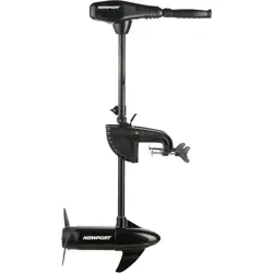
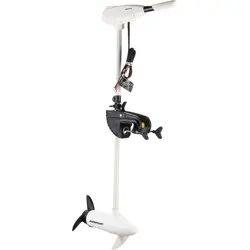
Thank you for purchasing the NK180 PRO
Electric Kayak Motor. We hope that you enjoy it!
The NK180 PRO Kayak Motor is designed
with direct-drive and field-oriented-control
technology to deliver the ultimate eciency
in a compact package. The propulsive power
of the NK180 PRO is roughly equivalent to a
1.8hp petrol outboard motor, but with silent and
emission free power delivery.
The NK180 PRO Electric Kayak Motor is
compatible with conventional 24V deep cycle
batteries, 24V LFP lithium battery, and 24V
lithium cobalt oxide batteries. The battery type
can be changed at the press of a button.
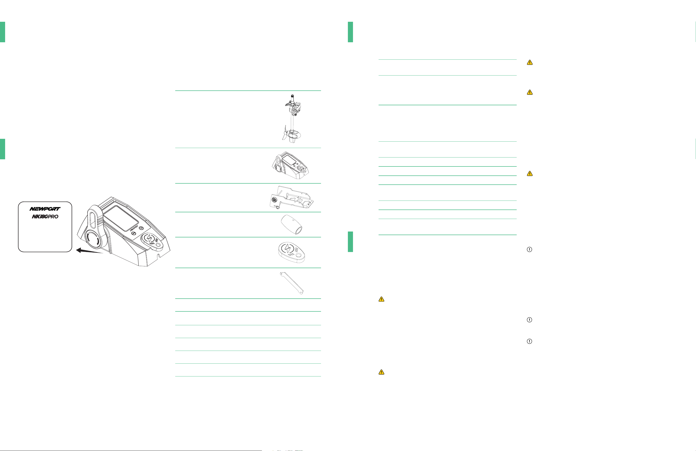
1.1 PRODUCT IDENTIFICATION
Check the figure below to find the serial number
of your product. You will need this as a reference
to access after-sale services. The serial number
is on the back of the product:
1.3 INCLUDED IN YOUR BOX
Here is what should be included in your NK300
Kayak Motor. Please contact us directly if
something is missing from this list of contents.
Items Qty Figure
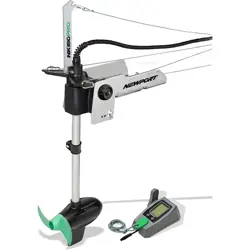
Motor Unit x1
Controller x1
Serial No. is at the back
of the controller
S/N - XXXXXXXXXXX
Electric Outboard Motor
Rated Power - 600W
Rated Input Voltage - 24V
Motor Mount x1
Cable Handle x2
Emergency Stop Key x2
Swing Arm x1
Nylon Lift/Reverse Cable x2
Battery Extension Cable
w/ Quick Connect
x1
Stainless Biner x4
SS Stainless Cable x2
Installation Kit x1
Signal Cable x1
Serial No. is at the back
of the controller
S/N - XXXXXXXXXXX
Electric Outboard Motor
Rated Power - 600W
Rated Input Voltage - 24V
6 7
3.2 BEFORE USE
• This motor should only be operated by an
adult who has thorough understanding and
command of the motor, including steering
functions, emergency stop switch, and
throttle.
• Always operate your boat and this motor in
compliance with local safety regulations.
• Always carry a paddle on board at all times,
especially when using an electric motor as
your primary method of propulsion.
• All passengers should wear approved life
jackets at all times.
• Check the status and condition of your
motor and battery before each trip. We
recommend starting every trip with a full
battery charge.
• Do not operate the motor outside of the
water.
• Do not modify the motor with non-original
parts.
3.3 DURING USE
• Stop the motor immediately if someone is
over board.
• Propellers are dangerous- use extra caution
when operating the motor near areas where
people may swim. Always be alert and aware
of your surroundings when operating the
motor.
• Do not exceed the recommended load and
power limitations of your boat as suggested
by its manufacturer.
3.4 AFTER USE
• Disconnect the motor from the battery after
use.
• Rinse the motor carefully with freshwater
after each usage, especially after use in
saltwater.
• Do not carry the kayak/boat by lifting with
the bracket. This can cause damage to the
boat and potentially to the bracket.
4 INSTALLATION
The next several pages will give you detailed
instructions on how to install your motor, one
piece at a time. Please read all instructions
carefully and refer to the diagrams.
4 INSTALLATION
4.1 INSTALLATION OF THE BRACKET
The next several pages will give you detailed
instructions on how to install your motor, one
piece at a time. Please read all instructions
carefully and refer to the diagrams.
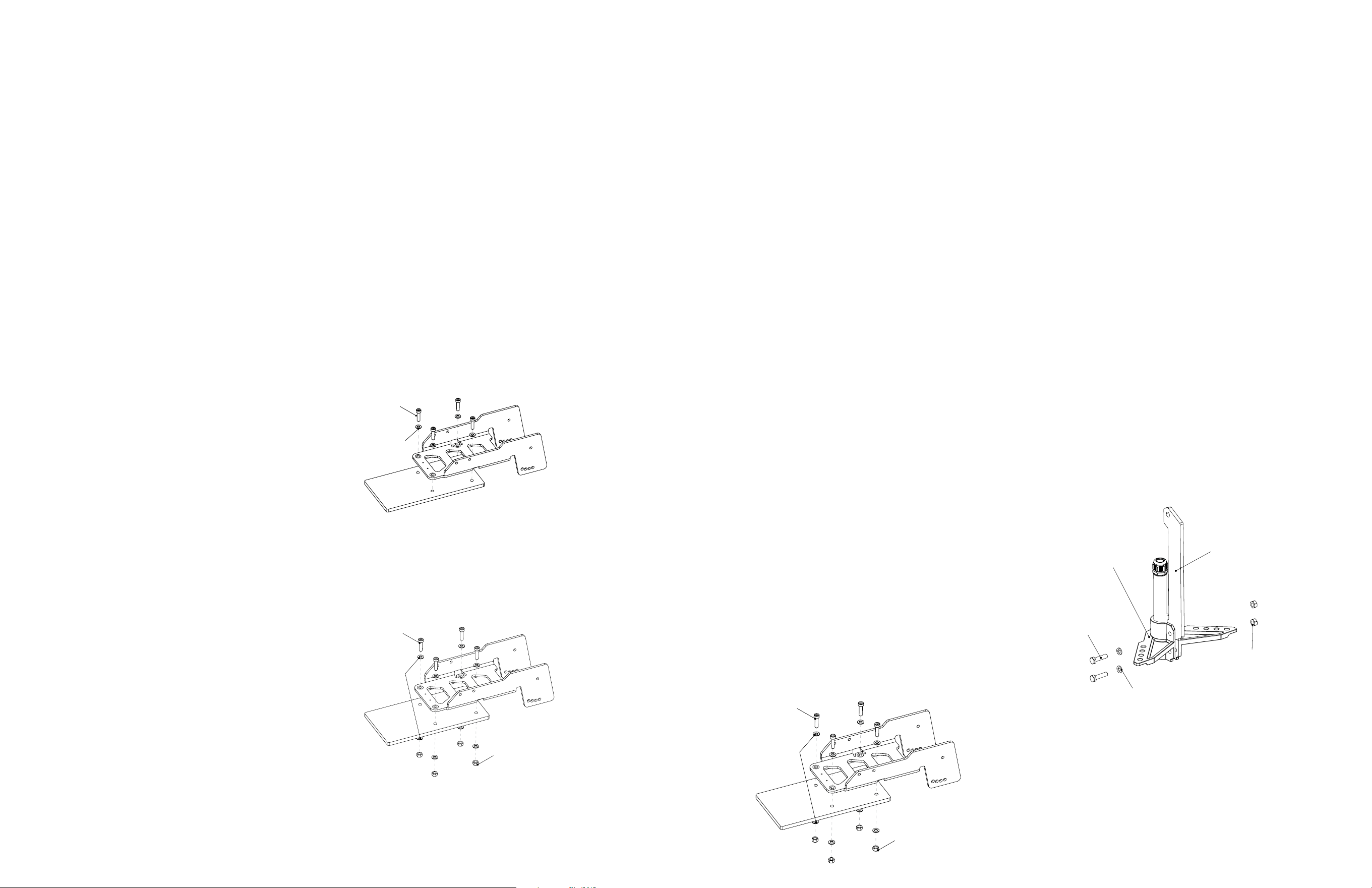
4.1.1 INSTALLATION USING EXISTING
THREADED INSERTS
1. Place the bracket above the threaded
inserts, align the holes on the bracket with
threaded inserts
2. Place four M8 screws and four washers
over the threaded inserts, as shown in the
diagram above, and tighten the screws to
mount the bracket. Make sure the screws
are tightened and the bracket is flush and
secure.
NOTE: We recommend applying torque of 140
in-lb (16Nm) to the screws.
4.1.2 INSTALLATION WITH DRILLING HOLES
USING A TEMPLATE
1. Find a proper location on your boat to drill
holes. The typical suggested location is the
end of the boat/kayak.
2. Drill holes 0.31in (8 mm) in diameter.
3. Place the bracket above the drilled holes,
align the holes on the bracket with the
drilled holes.
4. Place four M8 screws with washers over
the holes, and four washers with four nuts
beneath the holes, and tighten the screws
to secure the bracket. Make sure the screws
are tight and the bracket is flush on the deck
and secure.
NOTE: We recommend to apply a torque
of 140 in-lb (16Nm) to the screws. Different
kayaks may require different installation
hardware. If your kayak requires installation
hardware other than what is included in
this kit, please find it at your local hardware
store. Newport does not carry every possible
hardware combination necessary to fit all
brands and models of kayaks; however any
additional mounting hardware needed for your
individual craft should be standard, easy to find,
and low-cost.
4.1.3 INSTALLATION WITH AN ADAPTING
PLATE
1. Place the bracket above the adapting plate
and align the holes on the adapting plate
with the holes on the bracket.
2. Place four M8 screws and four washers
over the holes, four washers and four nuts
beneath the holes, and tighten the screws to
secure the bracket. Make sure the screws are
tight and the bracket is secure.
3. Install the adapting plate in the intended
location and make sure the adapting plate is
correctly installed and secure.
NOTE: We recommend to apply a torque of
140 in-lb (16Nm) to the screws.
4.2 SETTING UP YOUR STEERING
Kayaks feature many dierent cable routing
systems, while some more basic models have
no cable routing. To add cable routing to your
particular boat, contact the boat manufacturer
for recommendations.
Kayak cable routing can generally be broken
down into two categories: cables routed above
the deck of the kayak, and cables routed below
the deck of the kayak.
Cables routed above deck will usually demand
the steering triangle be mounted at the top of
the shaft.
This mount is designed to work with high routing
setups on kayaks equipped with integrated cable
routing.
For kayaks with cable routing requiring you to
use the high position, see section Setup with
Control Cords at the Top on page 14.
In some cases, further tweaks may be required
to refine the operation.
4.2.1 SETUP WITH CONTROL CORDS AT THE
TOP
If you have a kayak setup with control cords
running on the top of the kayak, follow the steps
below to finish the motor control cords setup:
1. Assemble the swing arm and steering
triangle as shown above, then insert the
screw, washer, and nut as shown and attach
loosely- don’t tighten yet.
2. Place the screw, washer and nut on the
clamping ring as figure shows, connect them
loosely and don’t tighten yet.
M8 screw
M8 washer
M8 nut
M8 screw
M8 washer
M8 screw
M8 washer
M8 nut
M6 screw
Washer
M6 nut
Steering triangle
Swing arm
See Our Product Quick Start Videos
for more information
8 9
3. Make sure the steering triangle is aligned
with the direction of the motor. If the triangle
is an arrow, it should point towards the front
of the boat, while the propeller should face
back.
4. Tighten the screws on the clamping ring and
the steering triangle.
In this setup, the steering triangle determines
the depth of the motor. Make sure the propeller
can be at least 2 inches (5 cm) below the water
surface.
4.2.2 ADJUSTNG MOTOR DEPTH OF WATER
AFTER SETUP
1. Hold the motor firmly and loosen the screw
on either the clamping ring or the steering
triangle, whichever is topmost on the shaft
in your set up.
2. Adjust shaft position to find the optimum
motor depth in water.
3. Tighten the screws on the clamping ring or
the steering triangle (whichever you have on
the top of the shaft).
NOTE: Be aware, the screw on the steering
triangle or the clamping ring must be
tightened well, otherwise the motor may fall
into the water!
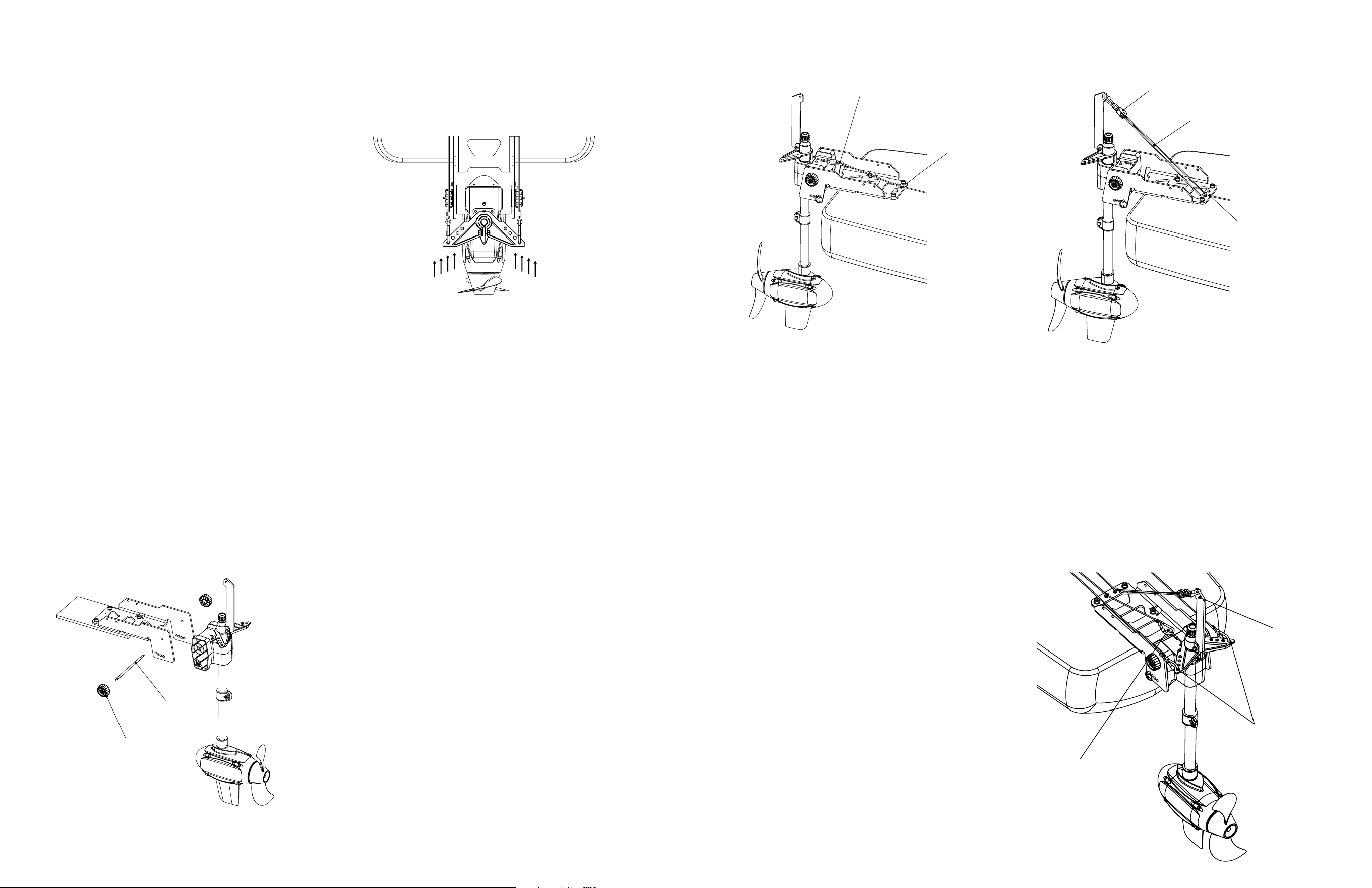
4.2.3 INSERTING THE MOTOR SUPPORTING
DRUM IN THE BRACKET
1. Place the motor assembly at the desired
position, align the hole on the drum to the
hole on the bracket.
2. Insert the drum shaft, make sure the shaft is
centered.
3. Install the knobs on both sides of the shaft.
Tighten the knobs.
4. Install the cotter pin on both sides of drum
shaft.
4.2.4 CONNECTING THE CORDS
Directional control has 4 options to adjust
steering fitment, feel and sensitivity. To control
the direction:
1. Secure the cable on one side of the stainless
steel biner.
2. Attach the stainless steel biner to the
steering triangle.
3. There are four options for steering
sensitivity. Attaching the cable to the outer
holes will mean direction changes happen
more gradually, while attaching it to the
inner holes will make direction changes
more sudden. It is recommended that you
start by hooking the stainless steel biner to
the outermost holes.
The cable to perform reverse lock:
The reverse lock secures the motor when it is
being used in reverse. It needs to be activated
when motor is used in reverse to keep the motor
from rotating up and out of water.
1. Tie the cable securely to one side of the
biner.
2. Attach the S biner to the reverse lock cord
as shown.
3. Thread the cord through the cable guide on
the bracket as shown.
4. Install the handle at the other end of the
cable.
5. Place the end of the cable where you can
access it easily.
6. You may choose to create a dedicated guide
for this cable near the handle location as
well. See newportvessels.com for more
products
The Cable to lift the motor:
1. Tie the nylon cable securely to one of the
eye nut.
2. Attach the stainless steel biner to the swing
arm as shown.
3. Thread the cord through the biner, and then
the cable guide (eye nut) on the bracket.
This is necessary to ensure proper function
of raise/deploy function.
4. Install the handle on the other end of the
cable.
4.3 COMPLETE THE CORD SETUP
This is the overall setup of the motor after all
control cables have been installed:
Drum pin
Tightening knob
Cable guide
Cord to perform the
reverse lock
Cord to lift the moto
r
Biner
Cable guide
Reverse lock cord
Cords to control
the direction
Motor lift cord
10 11
4.4 USING EXTERNAL STEERING SYSTEM
If you are planning on using the motor only for
forward/reverse propulsion and are using other
methods to steer such as a paddle, you can fix
the motor direction with the following steps:
1. Remove the cords on the steering triangle.
2. Insert the fixing screw into the hole as
shown.
3. Use the M3 Allen key to tighten the screw
securely.
4. Now the direction of the motor is fixed.
4.5 ADJUST THE MOTOR TRIM ANGLE
You can adjust the angle between water surface
and the motor using the motor trim angle
adjustment design. Follow the steps below if you
would like to change the angle of the motor.
1. Tilt the motor up and hold it firmly.
2. Remove the R shaped cotter pin from the
trim rod and pull the trim rod out from the
current trim position of the bracket.
3. Adjust the motor to the desired angle.
4. Reinsert the trim rod through one of the four
positions on the bracket, and insert the R
shaped cotter pin to secure the trim rod.
NOTE: Be careful of finger pinching. You can
use a flat head screw driver or needle nose
pliers to help remove the cotter pin.
4.6 CONNECT TO THE SPEED CONTROLLER
1. Find the signal cable coming from the motor
shaft and connect it to the speed controller.
Make sure the cable is tightly connected.
2. It is recommended to fit the cable into the
cable tidy slot underneath of the speed
controller.
3. You can choose to mount the speed
controller at the most convenient location for
operation. There are two M4 mounting holes
with nuts pre-installed on the back of the
speed controller which can be used to mount
when needed.
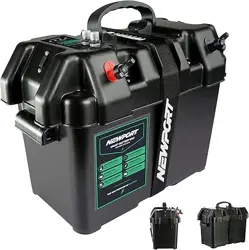
4.7 CONNECT TO THE BATTERY
The motor is adaptable with 24V (two 12V
batteries connected in series) deep cycle
marine battery package, 24V LFP lithium
battery (including two 24V LFP lithium batteries
connected in series) and 24V lithium cobalt
oxide battery package. Please follow the steps
below to complete the battery connection.
1. Connect the power extension cable with the
quick connect to your battery. The red cable
connects to the positive battery terminal
and the black cable connects to the negative
battery terminal.
2. Make sure the battery cables are connected
to the correct terminal. The motor will
not operate if battery cables are installed
incorrectly.
3. Tighten the connection of the battery cables
to the battery terminals. Make sure the
connection is solid and secure.
4. To power the motor, plug the connectors
from the motor and cable extension
together.
WARNING: Be sure all switches are in the OFF position
before connecting to battery or batteries. Electrical arcing
near the battery could cause an explosion. The battery
produces hydrogen and oxygen gases while charging. This
potentially explosive mixture escapes through the fill vent
cell caps and may form an explosive atmosphere around the
battery for several hours after it has been charged. Electrical
arcing or flames can ignite the gas and cause an explosion,
which may shatter the battery and could cause blindness or
other serious injury.
5 CONTROLLER DISPLAY
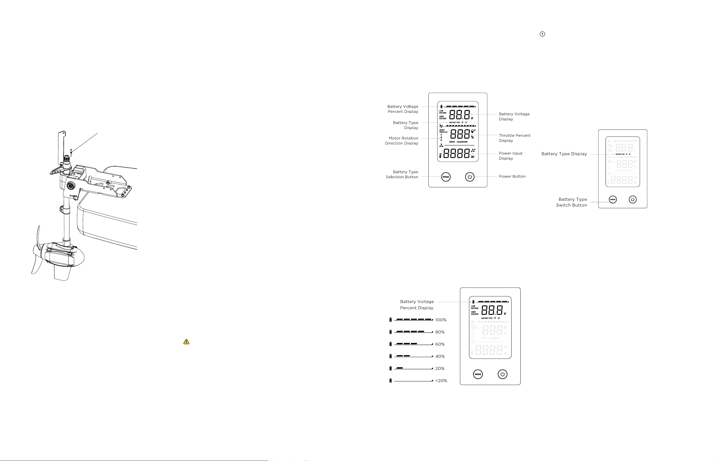
5.1 OVERVIEW OF MULTI-FUNCTION DISPLAY
The speed controller screen features motor and
battery information for the operator to monitor.
There are two buttons on the speed controller to
control the motor.
5.2 BATTERY DISPLAY
The speed controller screen features motor and
battery information for the operator to monitor.
There are two buttons on the speed controller to
control the motor.
5.2.1 ESTIMATED PERCENT OF REMAINING
BATTERY POWER
The battery bar has 6 dierent status levels
to display the estimated remaining battery
percentage.
CAUTION: Do not overestimate the remaining battery
range; this could result in severe harm or even death.
• Before you leave the dock, know the area you are
traveling, how far you plan to go, and make sure
to have an alternate plan for safely getting back if
anything goes wrong with your motor or battery.
Always bring a paddle.
• Monitor the battery level indicator during your trip
and always leave a buer for getting back to shore.
5.2.2 SWITCHING BETWEEN BATTERY TYPES
This motor can run on a 24V deep cycle battery
setup, a 24V LFP lithium battery setup, or a 24V
lithium cobalt oxide battery.
You will
need to
select
which
type of
battery
you are
using with
your
motor for
accurate
results on
the LCD screen. When the battery is connected
to the motor, press the MODE button to toggle
between the Li (LFP Lithium Battery or Lithium
Cobalt Oxide Battery) or D (Deep Cycle Battery)
battery options
Fixing pin
12 13
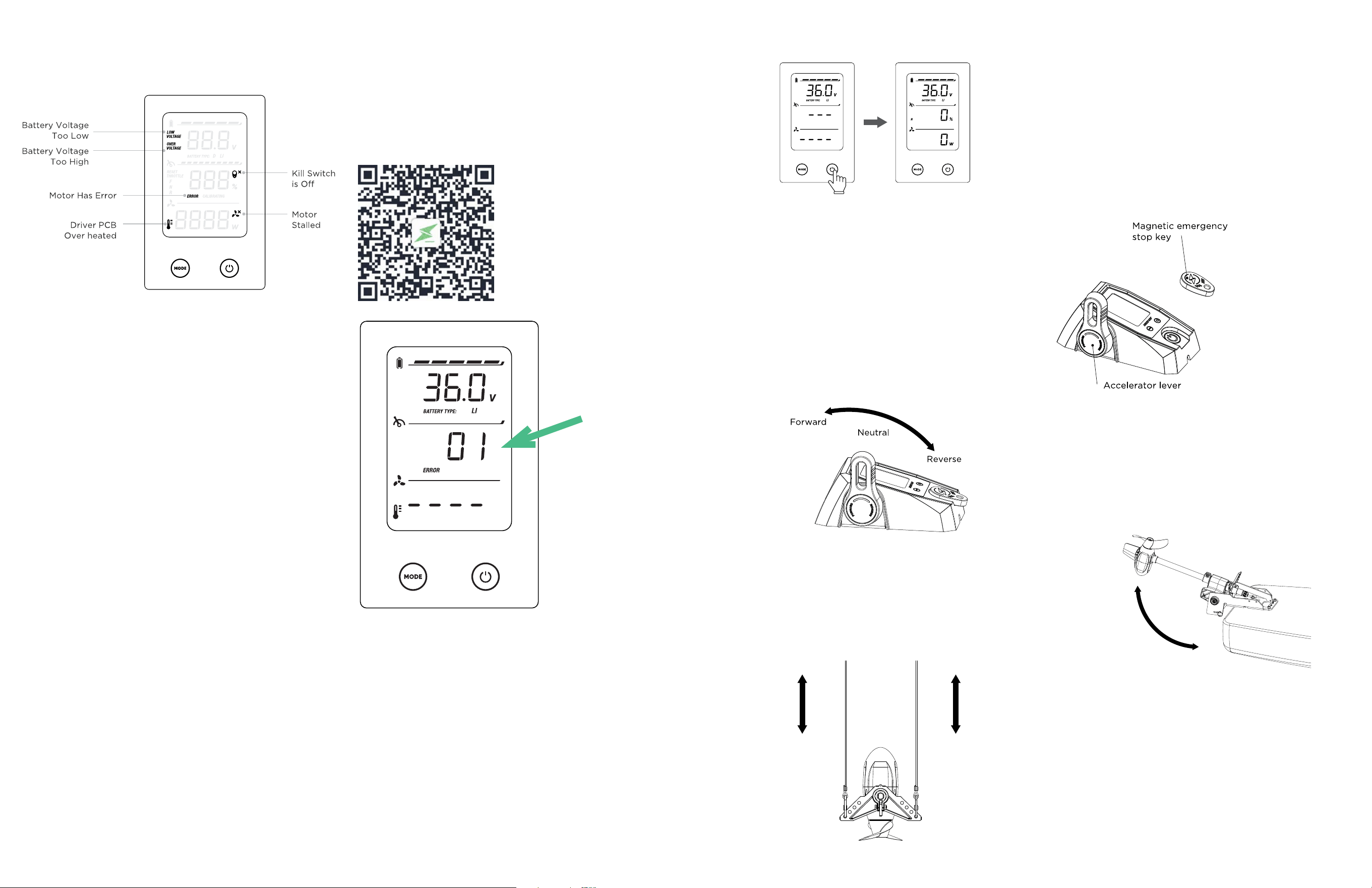
5.3 ERROR STATUS DISPLAY
The icons indicated on the LCD screen above
show three possible error statuses of the
motor. When a fault occurs, there will be a
corresponding code on screen to help diagnose
the problem. See section 5.4 Error Codes and
Solutions.
Motor overvoltage: If the input voltage is too
high, this icon will light up and keep flashing.
Please make sure the input voltage to the motor
is correct (24V or 25.9V). Ensure the correct
battery option is selected (D or Li).
Motor overheated: If the motor driver PCB is
over heated, this icon will light up.
Motor stalled: If the motor is stalled, this icon
will light up. Please disconnect from the battery
and check to see if the propeller has been
tangled in weeds or fishing line- these can also
get wrapped behind the propeller. Clean the
propeller and resume running.
5.4 ERROR CODES AND SOLUTIONS
If there is an issue with the motor function,
the display will show and error code to help
diagnose the problem and find the solution.
Scan the QR code below to access the Error
Code Reference Guide.
6 OPERATION
6.1 START THE MOTOR
To start the motor please follow the steps below:
1. Place the magnet kill switch on the tiller.
2. Select the battery mode according to the
battery type used. Please follow 5.2.2
Switching Between Battery Types to
operate correctly.
3. Press the power button on the panel.
4. You can now begin to power your motor.
6.2 TRAVEL FORWARD/REVERSE
The motor’s forward/reverse motion is
controlled by the accelerator lever on the speed
controller. Please refer to the diagram below
which demonstrates how to operate.
When switching to reverse, please pull the
reverse lock cable to lock the motor and
prevent it from tilting up and out of the water.
If the motor tilts up, briefly engage the forward
throttle while pulling the reverse lock; once the
lock is engaged, return throttle to reverse. If the
reverse lock is hard to achieve, adjust your setup
and try again.
6.3 STEERING THE MOTOR
While the motor is operating, pull the steering
cords to control the vessel’s direction:
• To turn left, pull the left cord on the steering
triangle.
• To turn right, pull the right cord on the
steering triangle.
6.4 EMERGENCY STOP
To stop immediately you can:
• Pull o the magnetic emergency stop switch
from the tiller
• Move the accelerator lever on the speed
controller to neutral
• If you want to restart the motor after the
emergency kill switch is pulled o, move the
handle of tiller to the neutral position, return
the kill switch, and power on.
6.5 STOPPING THE MOTOR
To stop the motor, follow the steps below:
• Move the handle of tiller to the neutral
position.
• Press the On/O button on the speed
controller.
• Remove the emergency kill switch.
6.6 TILTING THE MOTOR
When needed,
the motor can
be tilted up
to stow away
or to avoid
underwater
obstacles. To
do this, pull
the cord on
the swing arm
shown in the
figure to the right until the motor pulls out of
the water and secure the cord in the forward
position, keeping the motor out of water. Make
sure you secure the cord so that the motor will
not drop down when you let go.
6.7 FINISHING THE TRIP
When the trip is finished, please disconnect the
motor from the battery and take the motor out
of water. If the motor was used in the saltwater,
Pull the left cable
to turn left
Pull the right cable
to turn right
14 15
thoroughly rinse the motor with fresh water. This
will help prevent corrosion and salt buildup. Only
wash the motor; do not get the speed controller
wet.
6.8 STOW AND PARK THE MOTOR
When the motor needs to be stowed and
parked, tilt the motor up and use string or
bungee cord to bind the motor on the bracket.
Please use the figure below for reference.
6.9 REMOVE THE MOTOR FROM THE KAYAK
It is very easy to remove the motor from the
bracket for travel, however you will want to leave
the mount installed. Follow the steps below:
1. Move the accelerator lever to the neutral
position, and turn o the motor.
2. Disconnect the motor from the speed
controller and battery.
3. Detach all the control cords from the motor.
4. Loose the knobs on the motor support drum,
take out the drum shaft and lift the motor
from the bracket.
7 CARE AND SERVICES
7.1 CARE OF MOTOR COMPONENTS
• Please regularly follow all maintenance
tips to keep your motor in optimal working
condition.
• Do not start the motor in shallow water as it
may damage the propeller.
• After each use, check between the plastic
propeller and metal motor housing for
fishing line, weeds, or other debris. ALWAYS
DISCONNECT from power before working
near the propeller.
• Lubricate all the pivot points with a non-
aerosol lubricant. Never use an aerosol
lubricant, as many types contain harmful
propellants that can cause damage to
various parts of your electric motor.
7.2 CORROSION PROTECTION
• After the motor is used in the saltwater, rinse
the motor thoroughly with fresh water.
• Before storing the motor, make sure the
motor is completely dry and clean.
• Keep cable connectors and plugs in good
condition.
• Use a wire brush to remove corrosion when
necessary.
7.3 CARE OF BATTERY USAGE
• Check tightness of the battery lead
connections.
• Never connect the wires to the wrong
battery terminal. You must disconnect the
battery during maintenance.
• Recharge batteries after each use. Follow the
battery manufacturer’s recommendations for
battery maintenance.
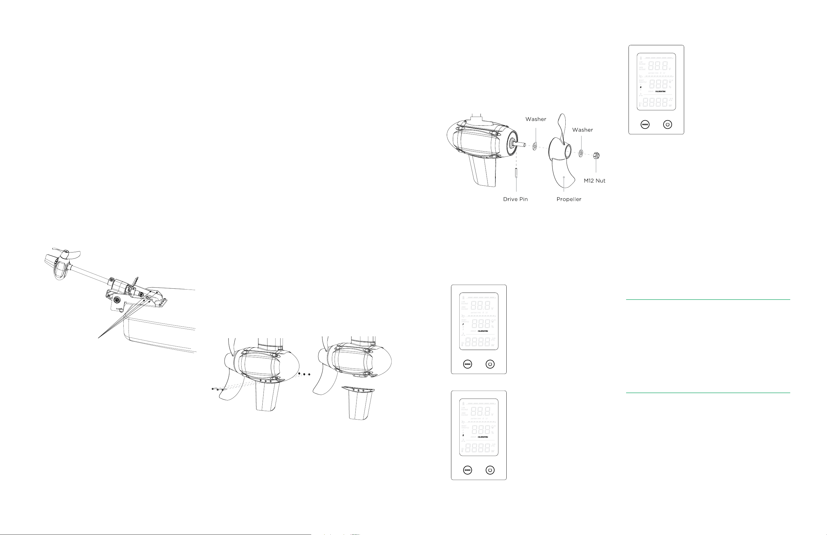
7.4 REPLACING THE FIN
You can replace the fin component if it is
damaged. To do this, follow the steps below:
1. Release the three M3 screws and nuts.
2. Remove the old fin component.
3. Insert the new fin component.
4. Insert three M3 screws and tighten them.
7.5 REPLACING THE PROPELLER
You can replace the propeller if it is damaged.
To do this, follow the steps below with the
assembly diagram:
1. Attach the washer.
2. Insert the drive pin into the hole on the
motor output shaft.
3. Rotate the propeller until the drive pin
is seated correctly in the corresponding
channel on the backside of the propeller.
4. Place the washer on the motor shaft after
the propeller.
5. Tighten the hex locknut with 17mm socket
wrench.
7.6 RECALIBRATE THE THROTTLE
You can recalibrate the throttle when the throttle
display is inaccurate. To do this, follow the steps
below:
• Press and the MODE button for 5 seconds,
the controller will enter the throttle
recalibration mode.
You will notice the
CALIBRATING sign
starts to flash.
• While the screen
displays the F icon,
move the handle
to the full throttle
forward position.
• Press the MODE
button again.
• While the screen
displays the R icon,
move the handle
to the full throttle
reverse position.
• Press the MODE
button again
• While the screen
displays the N icon,
move the handle to
the Neutral (middle)
position.
• Press the MODE
button again. And the
throttle recalibration
is complete. You
will notice the
CALIBRATING sign
stops to flash, press
the POWER button to
exit the recalibration mode.
• When the CALIBRATING sign flashes, it
means the recalibration is not finished yet,
exiting the throttle recalibration mode will
not change the current throttle setup.
• To exit the throttle recalibration mode at any
steps during the process, press the POWER
button.
DECLARATION OF CONFORMITY
FOR RECREATIONAL CRAFT
Propulsion Engine with the requirements of
Directive
89/392/EEC as amended by 89/336/EEC.
Engine type approved according to:
Directives 89/392/EEC, 89/336/EE
Description of Engine(s) and Essential
Requirements
Engine Type: Outboard Engine
Fuel Type: Electric
This declaration of conformity is issued under
the sole responsibility of the manufacturer. I
declare on behalf of the manufacturer that the
motor(s) is (are) in conformity with the type(s)
for which above mentioned EC, EMC and ROHC
type-examination or type approval certificate(s)
has (have) been issued and it will meet the
requirements of Directive 89/392/EEC, 89/336/
EEC as amended when installed in a recreational
craft, in accordance with the manufacturer’s
supplied instructions.
Pr
emade holes for tightening
motor in the stowed/ parked position
16 17
Newport designs innovative accessories crafted to
elevate your time on the water, propelling you further.
THE WAY FORWARD IS
WITH ACCESSORIES
NK180 PRO Electric
Kayak Motor
LoPRO Lithium
Battery
@newportvessels
SHARE YOUR
ADVENTURES
REV FX09X259