508269B01 Issue 2217 Page 1 of 9
(P) 508269B01
*P508269B01*
Blue Summit LLC
8201 C National Turnpike
Louisville, KY 40214
Improper installation, adjustment, alteration, service
or maintenance can cause property damage, personal
injury or loss of life. Installation and service must be
performed by a licensed professional installer (or
equivalent), service agency or the gas supplier.
WARNING
Risk of explosion or re.
Can cause injury or death.
Recover all refrigerant to relieve pressure before
opening the system.
WARNING
As with any mechanical equipment, contact with sharp
sheet metal edges can result in personal injury. Take
care while handling this equipment and wear gloves
and protective clothing.
CAUTION
The Clean Air Act of 1990 bans the intentional venting
of refrigerant (CFCs, HCFCs and HFCs) as of July
1, 1992. Approved methods of recovery, recycling or
reclaiming must be followed. Fines and/or incarceration
may be levied for noncompliance.
IMPORTANT
General
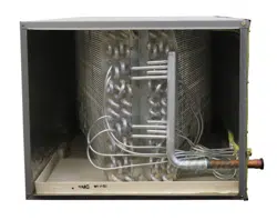
BH1P all-aluminum coil horizontal evaporator coils are
designed for use with air conditioners and heat pumps.
Each coil is equipped with a compression tting that
provides convenient eld installation of a properly sized,
separately ordered expansion valve.
The coil drain pan is high quality engineering polymer
with a maximum service temperature of 500°F. However,
adequate space must be provided between the drain pan
and furnace heat exchanger. At least 2” space is required
for heat exchanger and 4” for drum-type or oil-red furnace
heat exchanger. Closer spacing may damage the drain
pan and cause leaking.
Refer to the BH1P Technical Specication for proper use
of these coils with specic furnaces, air conditioners, heat
pumps and line sets.
These instructions are intended as a general guide and do
not supersede local or national codes in any way. Consult
authorities who have jurisdiction before installation.
NOTE: Special procedures are required for cleaning the
aluminum coil in this unit. See Page 8 in this instruction
for information.
Shipping and Packing List
Package 1 of 1 contains the following:
1 - BH1P evaporator coil
Check the components for shipping damage. If you nd
any damage, immediately contact the last carrier.
INSTALLATION INSTRUCTIONS
BH1P Indoor Coils
508269B01Issue 2217Page 2 of 9
Model Number Identication
B H 1P 24 A N - 50
Evaporator Coil
H = Horizontal
Metering Device
1P = Piston
Nominal Capacity
24 = 2.0 Ton
30 = 2.5 Ton
36 = 3.0 Ton
42 = 3.5 Ton
48, 51 = 4.0 Ton
60 = 5.0 Ton
Series
Color
N = Not Applicable
G = Platinum Gray
M = Galvanized Embossed
Matching Gas Furnace
Cabinet Width
A = 14-1/2
B = 17-1/2
C = 21
D = 24-1/2
508269B01 Issue 2217 Page 3 of 9
Releasing Air Charge
The coil is shipped from the factory pressurized with dry
air. Pierce a hole in the rubber plug that seals the vapor
line to relieve the pressure before removing the plugs.
CAUTION
NOTE: If there is no pressure released when the vapor
line rubber plug is pierced, check the coil for leaks before
continuing with the installation.
The coil is shipped with a 10 + 3 psig dry air holding
charge. Puncture the suction line rubber plug to release
the charge. Remove the rubber plug. Ensure that the coil
is void of pressure.
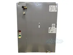
Installation
Risk of explosion or re.
Can cause injury or death.
Recover all refrigerant to relieve pressure before
opening the system.
WARNING
Install the furnace or air handler according to the installation
instructions provided with the unit.
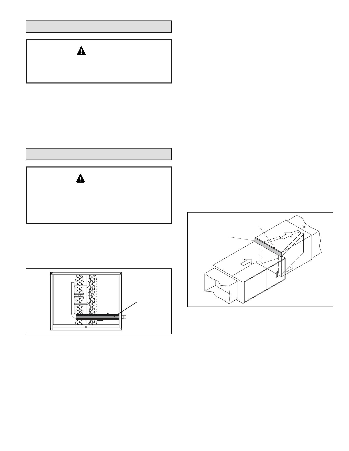
NOTE: In areas of high humidity, use foam tape to insulate
the suction line section in the cabinet as shown in Figure 1.
Figure 1. Insulate Suction Line Inside Cabinet
FOAM
TAPE
1. Left-Hand and Right-Hand Discharge — The coil
must have a 1/2” slope from the rear of the cabinet
to the drain. Position the coil adjacent to the furnace
cabinet and align the six screw clearance holes in the
coil casing with the furnace engagement holes. Use
six eld-provided #8 X 1” screws to secure the coil
casing to the furnace (see Figure 3 and Figure 4).
2. Right-Hand Air Discharge with Field-Provided
Spacer — The coil must have a 1/2” slope from the
rear of the cabinet to the drain. Position the coil in the
left-to-right conguration on the service access side
of the furnace. Insert a eld-provided spacer between
the furnace and the coil. Use eld-provided screws
to secure the coil casing, spacer and the furnace
together. The spacer should be long enough to allow
room for proper installation (approximately 6 inches
minimum). See Figure 5.
NOTE: When the coil is connected directly with a
condensing furnace, the coil must be level from
return end to supply end. The front (access side) of
the furnace may be pitched downward up to 1 inch to
accommodate a ½-inch pitched coil.
3. Secure the supply duct to the coil cabinet.
4. Refer to the instructions provided with the condensing
unit for leak testing, evacuating and charging
procedures. Always check the entire system for leaks
before charging.
5. Applications using BH1P-60 D-width unit with
C-width furnace — Figure 2 shows an application
that includes a D-width coil and a C-width furnace.
This application requires construction of an insulated,
eld-supplied block-o plate to cover the open space
on the coil housing.
Figure 2. D-Width Coil with C-Width Furnace
SUPPLY AIR UNIT
FRONT
PLUMBING
CONNECTIONS
SUPPLY AIR
UNIT REAR
TEST HOLE
AIR FLOW
FIELD‐FABRICATED
INSULATED BLOCK-
OFF PLATE
508269B01Issue 2217Page 4 of 9
Figure 3. Left-Hand Air Discharge
(Top View)
SUPPLY AIR UNIT FRONT
PLUMBING
CONNECTIONS
SUPPLY AIR UNIT REAR
AIR FLOW
TEST HOLE
SLOPE 1/2”
(13 MM)
90% GAS FURNACE
DRAIN
COIL DRAIN
SUPPLY AIR UNIT
FRONT
BACK
COIL
(SUPPLY AIR END VIEW)
AIR
FLOW
Figure 4. Right-Hand Air Discharge
COIL
FRONT
NOTE - Use of this orientation is acceptable for 80% AFUE furnaces.
Do not use this orientation for 90% condensing furnaces.
(SUPPLY AIR END VIEW)
SUPPLY AIR UNIT FRONT
PLUMBING CONNECTIONS
SUPPLY AIR UNIT REAR
TEST HOLE
SLOPE 1/2”
(13 MM)
COIL
DRAIN
SUPPLY AIR UNIT
SUPPLY AIR
UNIT FRONT
COIL
AIR FLOW
(Top View)
AIR
FLOW
Figure 5. Right-Hand Air Discharge with Spacer
FIELD-PROVIDED SPACER
(6 IN.)
COIL
BACK
FRONT
SUPPLY AIR UNIT FRONT
PLUMBING CONNECTIONS
SUPPLY AIR UNIT REAR
TEST HOLE
SLOPE 1/2”
(13 MM)
COIL DRAIN
SUPPLY AIR
UNIT FRONT
(TOP VIEW)
AIR FLOW
90% GAS FURNACE
DRAIN
(SUPPLY AIR END VIEW)
AIR
FLOW
508269B01 Issue 2217 Page 5 of 9
Refrigerant Line Connections
Line Sizes
The refrigerant line sets should be sized according to the
recommendations given in the outdoor unit installation
instructions. See Table 1 for sweat connection sizes. A
eld-provided adapter may be required to match line set
connections.
Model
Suction Line
Connection
Liquid Line
Connection
-24
-30
-36
3/4 inch
3/8 inch
-42
-48
-51
-60
7/8 inch
Table 1. Refrigerant Line Connections
Replacement Parts
If replacement parts are needed for the liquid line orice
housing or assembly, order kit 69J46. The kit includes:
• 10 - Brass nuts for liquid line assemblies
• 20 - Teon rings
• 10 - Liquid line orice housings
• 10 - Liquid line assemblies
Figure 6. Liquid Line Orice Kit (69J46) Components
TEFLON RINGS (20)
BRASS NUTS (10)
LIQUID LINE ASSEMBLIES
(INCLUDES STRAINER) (10)
LIQUID LINE ORIFICE HOUSINGS (10)
LIQUID LINE
ASSEMBLY
COPPER
TUBE
PISTON
RETAINER
STRAINER
Brazing Guidelines
Use a silver alloy brazing rod (5 or 6 percent silver alloy for
copper-to-copper connections or 45 percent silver alloy for
copper-to-brass or copper-to-steel connections).
Use AL822 Flux Cord Solder Stickers (catalog number
Y6331) for aluminum to aluminum joints.
Before making brazed connections, place a eld-provided
heat shield, such as a wet rag, against the unit cabinet and
around the piping stubs. The heat shield must be in place
to prevent heat damage during brazing. See Figure 7.
Figure 7. Brazing Refrigerant Lines
WATER-
SATURATED RAGS
PLACE A WET RAG AGAINST
COIL CABINET AND AROUND
THE SUCTION LINE
CONNECTION.
BRAZE CONNECTION. ALLOW
PIPE TO COOL BEFORE
REMOVING WET RAG.
1
2
Suction Line Connection
Use the following procedure to connect the suction line to
the indoor coil:
1. Remove rubber plug from the stubbed connection.
2. Position the properly sized refrigerant piping and
make the brazed connection following the brazing
guidelines.
3. Do not remove the water-saturated rags from the
cabinet and piping until the piping has cooled
completely.
Suction Line Equalizer Fitting
Remove the copper are seat bonnet if present from the
male equalizer line tting (see Figure 8).
When removing the are nut, ensure that the copper
are seal bonnet is removed as illustrated in Figure 8.
IMPORTANT
Figure 8. Suction Line Male Equalizer Line Fitting
Modications
SUCTION LINE
FLARE NUT
REMOVE AND DISCARD
FLARE SEAL BONNET IF
PRESENT
MALE BRASS EQUALIZER
LINE FITTING
FLARE SEAL CAP
OR
508269B01Issue 2217Page 6 of 9
Liquid Line Connection
NOTE: Before the liquid line connections can be made,
the factory-provided refrigerant metering orice must be
removed and a properly sized expansion valve must be
eld-installed.
The system must include a properly matched expansion
valve which must be eld-provided and installed. The BH1P
is shipped with a factory-installed refrigerant metering
orice. The orice must be removed BEFORE a properly
sized expansion valve is installed.
Fixed Orice Removal
1. Remove any shipping clamps holding the liquid line
and distributor assembly.
2. IMPORTANT: Using two wrenches, disconnect the
liquid line stub from the orice housing. Take care not
to twist or damage the distributor tubes during this
process.
3. Remove and discard the existing orice, valve stem
assembly (if present) and Teon ring as illustrated in
Figure 9.
4. Retain brass nut to be used later with the liquid line
assembly.
O-RING
REMOVE AND DISCARD
WHITE TEFLON® SEAL
STRAINER
DISTRIBUTOR
TUBES
LIQUID LINE
STUB
ORIFICE HOUSING
(REMOVE ORIFICE
FROM INSIDE OF
HOUSING)
BRASS
NUT
Figure 9. Typical Fixed Orice Removal
Expansion Valve / Liquid Line Installation
A properly matched expansion valve must be used with
the BH1P units. The expansion valve can be installed
internal or external to the indoor coil cabinet. Refer to
the instructions provided with the expansion valve kit for
proper installation of the valve and sensing bulb.
See the BH1P Technical Specication for approved
expansion valve match-ups and application information.
Leak Testing, Evacuating and Charging
Refer to the outdoor unit instruction for leak testing,
evacuating and charging procedures. Always leak check
entire system before charging.
The following best practices are recommended to ensure
better condensate removal:
• Main and overow drain lines should NOT be smaller
than both drain connections at drain pan.
• Overow drain line should run to an area where
homeowner will notice drainage.
• It is recommended that the overow drain line be
vented and a trap installed. Refer to local codes.
Sealing Ducts
Ensure the duct is secured and all joints are properly
sealed to the coil cabinet anges.
There must be an airtight seal between the bottom of
the furnace and the return air plenum. Use berglass
sealing strips, caulking, or equivalent sealing method
between the plenum and the air handler cabinet to
ensure a tight seal. Return air must not be drawn from a
room where this air handler or any gas-fueled appliance
(i.e., water heater), or carbon monoxide-producing
device (i.e., wood replace) is installed.
WARNING
DUCT SYSTEM SIZING - The duct system should be
properly sized and installed according to the ASHRAE
Standard Manual D. The supply and return air duct
systems should be designed for the cfm and static
requirements of the job. Consult the blower performance
chart in the unit installation instructions to verify that the
blower meets the application requirements.
IMPORTANT
Condensate Drain Connections
After removal of drain pan plug(s), check drain hole(s)
to verify that drain opening is fully open and free of any
debris. Also check to make sure that no debris has
fallen into the drain pan during installation that may plug
up the drain opening.
IMPORTANT
Main Drain
Connect the main drain and route downward to drain line
or sump. Do not connect drain to a closed waste system.
See Figure 11 for typical drain trap conguration.
Overow Drain
It is recommended that the overow drain is connected to
a overow drain line for all units. If overow drain is not
connected, it must be plugged with provided cap.
508269B01 Issue 2217 Page 7 of 9
Best Practices
The following practices are recommended to ensure better condensate removal:
• Main and overow drain lines should NOT be smaller than drain connections at drain pan.
• Overow drain line should run to an area where homeowner will notice drainage.
• It is recommended that the overow drain line be vented and a trap installed. Refer to local codes.
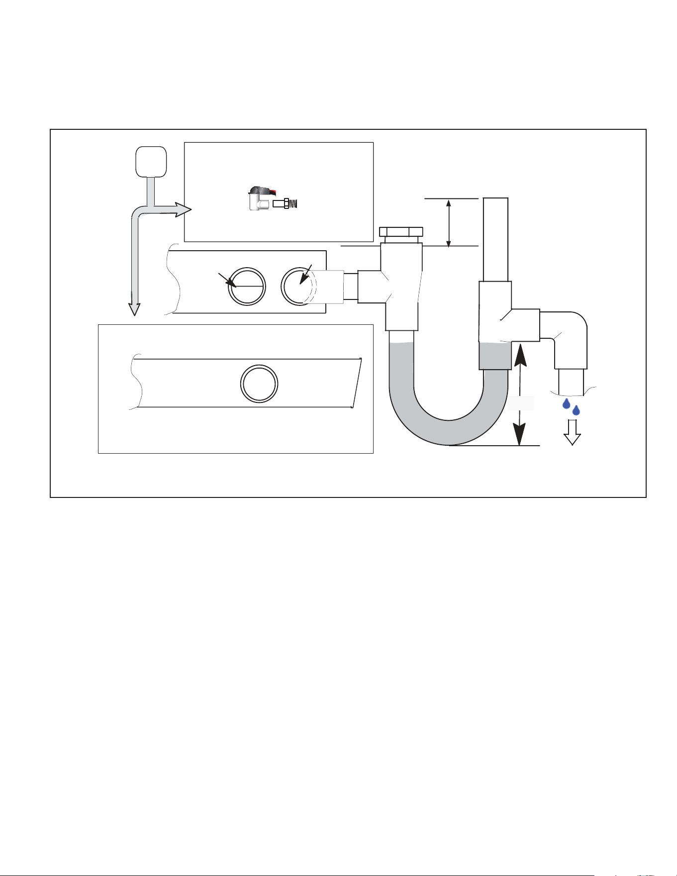
Figure 11. Right-Hand Air Discharge with Spacer
ABOVE
FINISHED
SPACE?
OVERFLOW DRAIN LINE
ALWAYS RUN AN OVERFLOW DRAIN LINE. IF NOT POSSIBLE TO
ROUTE OVERFLOW DRAIN LINE, INSTALL LOW VOLTAGE
OVERFLOW SWITCH KIT. WIRE KIT TO SHUT DOWN
COMPRESSOR PER INSTRUCTIONS.
NO
YES
CLEAN OUT
VENT
PRESS IN
(DO NOT GLUE)
VENT MUST EXTEND
ABOVE HEIGHT OF
COIL DRAIN PAN BY
TWO INCHES
1” X 3/4” X 3/4”
REDUCING
TEE WITH
PLUG
PVC SCH 40 P-
OR J-TRAP 3/4”
OVERFLOW
DRAIN
OPTIONAL
SAFETY
PAN
COIL DRAIN PAN
WHEN A COIL IS LOCATED ABOVE A FINISHED SPACE, A 3/4” SECONDARY DRAIN LINE
MUST BE:
●CONNECTED TO SECONDARY DRAIN PAN OR
●CONNECTED TO THE OVERFLOW DRAIN OUTLET OF THE AIR HANDLER DRAIN PAN.
TRAPS MUST BE DEEP ENOUGH TO OFFSET MAXIMUM STATIC DIFFERENCES —
GENERALLY, TWO INCHES.
DRAIN LINE SHOULD
SLOPE A MINIMUM OF
ONE INCH PER 10 FT.
NOTE — WHEN A AIR HANDLER IS LOCATED ABOVE A FINISHED SPACE THE SECONDARY
DRAIN PAN MUST HAVE A LARGER FOOTPRINT THAN THE AIR HANDLER.
MAIN
DRAIN
TO APPROVED
DRAIN
FOR NEGATIVE PRESSURE COILS (BLOWER
AFTER COIL), TRAPS ARE REQUIRED ON ALL
DRAIN LINES CONNECTED TO COIL.
COMPACT OVERFLOW SWITCH WITH 3/4” FEMALE SLIP INLET
AND MALE ADAPTER, TWO-PART DESIGN FOR USE WHERE
OBSTRUCTIONS PREVENT DIRECT THREADING
SECONDARY
DRAIN PAN
2”
(51MM)
TRAP DEPTH
508269B01Issue 2217Page 8 of 9
Blower Speed Connection
Proper air volume must be provided over the evaporator
coil. Select a blower motor speed tap that will provide 400
± 50 CFM per 12,000 Btuh of cooling capacity (wet coil).
A static pressure reading must be taken to see if the
pressure drops are within the proper range. See Figure 12
as an example to obtain an accurate reading.
To ensure accuracy, test the air on both sides of the coil.
Refer to Figure 12 for location of two test holes.
Figure 12. Static Pressure Test
LEFT-HAND AIR DISCHARGE (TOP VIEW)
SUPPLY AIR UNIT FRONT
SUPPLY AIR UNIT REAR
AIR
FLOW
TEST HOLE 1
TEST HOLE
2
SUPPLY
AIR DUCT
RETURN AIR
DUCT
Take care when drilling test holes into the furnace ange
and the duct. Drill holes away from refrigerant piping.
Test holes should be drilled where specied in order to
avoid unit damage.
CAUTION
1. Drill a 5/16” test hole in the coil case 1” from the
furnace ange (test hole 1, Figure 12).
2. Drill a 5/16” test hole into the supply air duct (test hole
2, Figure 12).
3. Connect the zero end of the draft gauge scale to the
furnace end of the coil. Insert the hoses so that 1/4”
extends inside the duct or end seal. Seal around holes
with Permagum.
4. Turn on the electrical power to the furnace and set the
thermostat to initiate a cooling demand.
5. Table 2 lists the range of air volumes and equivalent
draft gauge readings for this unit. Observe the draft
gauge reading. If the reading is below the required air
volume, increase the blower speed; if the reading is
above the required air volume, decrease the blower
speed. Refer to the furnace wiring diagram for blower
speed settings.
6. When the required draft gauge readings are obtained,
remove the draft gauge lines and insert snaphole
plugs into the test holes.
Cabinet
Vol: CFM
Drop: in. w.g.
Model Width in. Dry Wet
-24A 14-1/2 800 .15 .19
-24B 17-1/2 800 .09 .11
-30A 14-1/2 1000 .24 .27
-30B 17-1/2 1000 .14 .16
-36A 14-1/2 1200 .30 .39
-36B 17-1/2 1200 .16 .21
-36C 21 1200 .15 .18
-42B 14-1/2 1400 .26 .31
-42C 17-1/2 1400 .18 .21
-48B 17-1/2 1400 .25 .29
-48C 21 1600 .27 .30
-51C 21 1600 .25 .29
-60D 24-1/2 2000 .24 .30
Table 2. Air Volume/Static Pressure Drop Across Coil
Maintenance
Cleaning The Coil
The coil should be inspected twice each year and cleaned
at least once per year or more, if necessary. Indoor coil
cleaning should be performed by a licensed professional
service technician (or equivalent).
A damaged coil n can aect equipment operation and
performance. Do not use ame, high-pressure water,
steam, or volatile cleaners on ns or tubing surfaces. If
cleaning requires the use of acidic or alkaline cleaners,
follow the manufacturer’s instructions. Thoroughly ush
cleaner from all equipment components. (Be careful
to prevent damage or corrosion of the components
connected to the system or areas surrounding the
equipment being cleaned.)
CAUTION
Do not use hydrouoric acid, alkaline, or similar chemicals
to clean coils. These chemicals are not necessary to
dissolve salt, and may damage the n coating. Acid washes
are used to dissolve oils and greases, which generally are
not present on residential applications.
Do not use alkaline washes. Alkaline washes are useful
for dissolving oxides such as zinc oxide, aluminum oxide,
and iron oxide (rust). However, these three oxides are
more corrosion resistant than base metals, so dissolving
or removing them will cause an increase in corrosion.
508269B01 Issue 2217 Page 9 of 9
1. Before beginning this or any other maintenance,
turn o all power to the indoor unit at the main unit
disconnect switch. It is also recommended that you
wear personal protective gear: safety glasses and/or a
face shield, waterproof clothing and gloves.
2. Remove the coil from the indoor unit cabinet, and take
the coil to a place that is appropriate for cleaning it.
3. Vacuum or brush the coil to remove matted and surface
debris from the ns (dirt, hair, etc.). Use vacuum
attachments and /or brushes that will not damage the
coil ns.
4. Use only clean potable water to clean the coil. Clean
the coil from top to bottom.
NOTE: For units in coastal regions, fresh water will
dissolve away any salt deposits. (Wash coils with fresh
water at least every six months.)
Failure to follow instructions will cause damage to the
unit.
This unit is equipped with an aluminum coil. Aluminum
coils may be damaged by exposure to solutions with
a pH below 5 or above 9. The aluminum coil should
be cleaned using potable water at a moderate pressure
(less than 50psi). If the coil cannot be cleaned using
water alone, it is recommended to use a coil cleaner
with a pH in the range of 5 to 9. The coil must be rinsed
thoroughly after cleaning.
In coastal areas, the coil should be cleaned with potable
water several times per year to avoid corrosive buildup
(salt).
NOTE
5. Spray the coil at a vertical angle of 30 to 45 degrees
with a constant stream of water at moderate pressure
(less than 50 psig). A pressure washer with a fan
nozzle will work best. Do not spray the coil from a
horizontal direction.
6. Direct the spray so that any debris is washed out of the
coil and basepan. For most residential units, hot water
is not necessary.
NOTE: Attempting to back ush from the inside of the
coil will require removing parts from the unit, and it
may be very dicult to ush the whole coil surface.
Attempting to blow water through a coil will slow the
water stream and reduce the ushing action of the
outer n surface.
7. Replace the coil into the cabinet or plenum. Ensure
that you have followed the proper procedure for routing
and securing the refrigerant tubing.
Ensure that the distributor lines are not rubbing together
or kinked. All tubes must have enough clearance from
other metal parts. Use wire ties to secure tubes to
prevent movement that could cause the refrigerant
tubing to fail. Adjust the tubes as necessary.
IMPORTANT