UAL
REV062824
WHOLE HOUSE DUCTED DEHUMIDIFIER
MODEL NO: QHD070AUDH26WH
Installation
Operation
Maintenance
Owner’s Manual
IMPORTANT NOTICE:
Please read this manual carefully before installing
or operating your new air conditioning system.
Be sure to save this manual for future reference.

1. Safety Precautions
Please read all instructions thoroughly before using this product. Users of electrical products may
encounter hazards, including but not limited to injury, fire, or electric shock. Failure to adhere to
these instructions may result in damage to the machine and void the warranty. Proceed to remove
all packing materials and inspect for any damage or missing items that may have occurred during
transportation. Verify that the power supply matches the equipment's specified power requirements.
▪ Do not operate the equipment if the power cord or plug is damaged.
▪ Do not lay the power cord under the carpet.
▪ Do not cover the power cord with carpets or similar covers.
▪ Do not route the power cord under furniture or appliances. Ensure the power cord is arranged
away from high-traffic areas to prevent tripping hazards.
▪ Do not touch the product or plug with wet hands or while standing in water.
▪ Do not use this product in areas where gasoline, paint, or other flammable items are stored.
▪ Do not use this machine in environments with corrosive gases (such as sulfur oxide,
atmosphere, alcohol, etc.) as it may cause machine failure.
▪ Do not insert objects into the inlet door or vent within one month. This may damage the
equipment and void the warranty.
▪ Do not place the machine near furnaces, heaters, or other heat sources as this may cause
melting, fire, or electric shock.
▪ Do not block the air inlet valve or air outlet on the equipment. Ensure no water enters the
machine to prevent machine failure or electric shock. Direct airflow away from the face or body.
Do not operate the equipment under these conditions.
▪ To reduce the risk of injury, disconnect the power supply before performing maintenance.
▪ Remove the power cord from the power socket by grasping and pulling the plug end. Do not pull
the power cord itself.
▪ Do not attempt to repair or adjust any electrical or mechanical functions of this equipment as it
may cause danger and void the warranty.
▪ Do not continue to use the equipment if it is damaged or faulty. Turn off the product and
disconnect it from the power outlet. Refer to the troubleshooting guide or contact a professional
maintenance person.
▪ When not in use, store the equipment in dry areas, away from extreme temperature and humidity
environments. Always hold the retractable handle and keep the device upright.
▪ Do not tilt or reverse the machine when it is not in use.
1
2
1. Safety Precautions (continued)
▪ Before using the dehumidifier, set the product flat for more than 1 hour to stabilize the
refrigerant.
▪ If the dehumidifier has been tilted or inverted, it must be placed horizontally and left for at least
24 hours before use.
▪ The dehumidifier must always be placed horizontally for optimal efficiency.
▪ It is recommended to keep all doors, windows, and other exterior openings of the room closed
so the dehumidifier can operate effectively within a confined area.
▪ The dehumidifier is designed to operate within an ambient temperature range of 5°C to 40°C
(41°F to 104°F) and a relative humidity level of 20.0% or higher.
▪ If the room's temperature and humidity levels exceed this range, the dehumidifier may not
function properly.
▪ The power cord is 10-1/2 feet long, and the drain hose is 6 feet long. When in use, the power
cord should be connected to a power supply, and the drainage hose should be connected to a
drainage area. Ensure the drain hose is not lifted more than 16 feet above the floor to prevent
performance issues.
▪ The air intake and exhaust must be at least 8 inches from the wall to ensure proper operation.
▪ If the machine will not be used for an extended period, turn it off and unplug the power cord.
▪ Clean the filter regularly and ensure the drainage pipe is not blocked to maintain smooth
drainage.
Installation Safety Precautions
• The dehumidifier uses environmentally friendly R32 refrigerant, which is colorless, odorless, and combustible.
• Ensure the room for installing, operating, and storing the dehumidifier is larger than the specified area.
• Do not puncture or ignite the dehumidifier.
• Store the dehumidifier in a way that prevents mechanical damage from accidents.
• Keep the dehumidifier in a room free from continuous fire sources (e.g., open flames, lit gas appliances, electric heaters).
• Conduct safety checks before maintaining or repairing dehumidifiers using combustible refrigerants to minimize fire risk.
Maintenance Precautions
• Due to the special nature of R32 refrigerant, contact an authorized service center for repairs or scrapping.
• Maintenance by unqualified or non-professional personnel can be hazardous.
• Strictly follow the manufacturer's requirements when maintaining the dehumidifier.
Special Notice
Disposing of this appliance improperly, or in other natural surroundings, endangers your health
and is bad for the environment. Hazardous substances may leak into the ground water and enter
the food chain. Please follow proper disposal protocol.
3
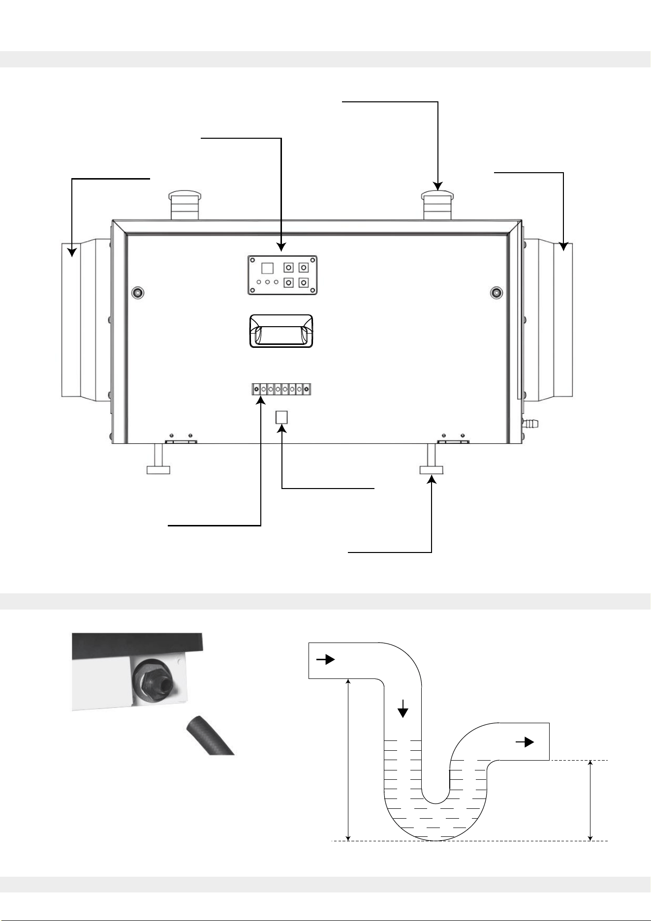
2. Structural Overview
3. Prior to Use
Control Panel
Cable Interface
Terminal Block
Support Base
Carrying Handle
Outlet Flange
Inlet Flange
Minimum 5 in.
Minimum 2.5 in.
Connect a 3/4" NPT drain fitting to the drain port.
Use clamps and snap rings to secure drain fittings.
To ensure smooth drainage, install the drain piping
with a continuous downward slope and connect it
to appropriate drains or condensate pumps.
Use a 1/2” drain hose to
connect the drain port.
4
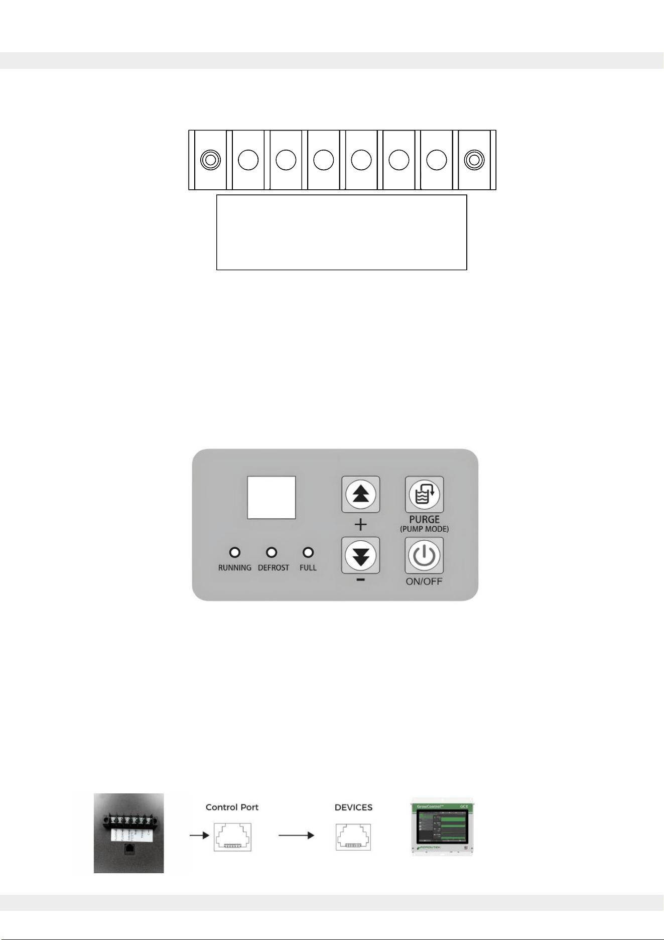
i. Terminal Block Layout
ii. Onboard Controller
iii. Unified Control via RJ12 Port
4. Methods of Control
▪ FLOAT(2): External low pressure water level sensor or float switch
▪ DHUM: Compressor and Fan during dehumidification operation
▪ R: 12VDC Output
▪ FAN: Running Fan in Ventilation Mode
▪ C: 12 VDC Output
External 12VDC devices can be powered by terminals R and C.
▪ Power Key: For On/Off operation. Press to turn the system on and off.
▪ Purge Key: For One-Touch drainage. Press to start water pump drainage.
▪ PLUS Key: Value adder. Press to increase the value of the selected parameter.
▪ MINUS Key: Value subtractor. Press to decrease the value of the selected parameter.
Connect an external controller via the terminal model RJ12, 6P6C protocol, or Modbus serial communication.
Send Control/Query commands, switch the machine On/Off, set humidity values or fan speeds, enable or
disable continuous dehumidification mode, query the current temp. or humidity, and display any fault codes.
FLOAT -
FLOAT -
DHUM -
R -
FAN -
C -

Press the "on-off" key to turn on the dehumidifier. The dehumidification function will activate.
Pressing the power button again will turn off the dehumidification function.
The humidity setting range is 30% to 90%, with the default humidity set to 30% when powered on for
the first time.
To adjust the humidity level, the "increase" or "decrease" keys should be pressed to change the
setting in 1% increments. Holding the key for 3 seconds will quickly adjust the setting.
If no operation is performed for 3 seconds, the current setting will be saved, and the adjustment
mode will exit.
If the humidity is set to 30% and the "decrease" key is pressed again, the dehumidifier will enter
continuous dehumidification mode (regardless of the current humidity level, the compressor will
keep running).
▪ When the ambient humidity exceeds the set humidity by 3% or more, the fan will start, and the
compressor will start after 3 seconds.
▪ When the ambient humidity is less than 3% below the set humidity, the compressor will stop, and
the fan will stop after 3 seconds.
Upon first startup, there is no 3-minute delay protection for the compressor. During normal
operation, the compressor's startup and shutdown are based on both humidity conditions and a
3-minute protection delay.
1) Automatic Drainage
When the system detects that the water tank is full, the compressor and fan will continue running,
and the water full indicator will flash (no fault code will be displayed). The water pump will start and
run for 40 seconds to drain the water. If the full signal is cleared, the draining process will stop.
If the full signal is not cleared within 60 seconds, the unit will stop, and the fault code and water full
indicator will flash.
2) Manual Drainage
After turning on the power, pressing the manual drain button once in any state will start the water
pump, which will run for 40 seconds. If the full signal is cleared, the draining process will stop.
The water full indicator will flash during this process.
5
5. Dehumidification Operation
6. Drainage Function

6
7. Power-On Self Test (POST)
After powering on, all displays and indicators light up for 2 seconds, and the buzzer beeps briefly.
Simultaneously, the system conducts a self-test on communication and each sensor.
If the detection is normal, the unit enters the shutdown state (three alarms may occur).
8. Compressor Protection for Three Minutes
After the compressor is stopped, a waiting period of 3 minutes is required before it can start again.
After the compressor starts, it must run for 3 minutes before it can stop.
When the power is turned on for the first time, there is no 3-minute delay protection for the
compressor to start.
9. Defrost Function
1) Entering Defrost Mode
This model uses a fan-based defrosting method. In dehumidification mode, when the coil
temperature is less than or equal to 30°F and the duration is greater than or equal to 15 minutes,
the defrost mode is activated.
The compressor turns off, the fan runs, the defrost indicator flashes, and the dehumidification
indicator turns off.
2) Exiting Defrost Mode
Defrost mode is exited when the coil temperature is greater than 37°F and the duration is greater
than 3 minutes.
The fan continues running, the compressor turns on, the defrost indicator turns off, and the
dehumidification indicator turns on.
7
10. Technical Data
i. QHD070AUDH26WH Dehumidifier Specifications
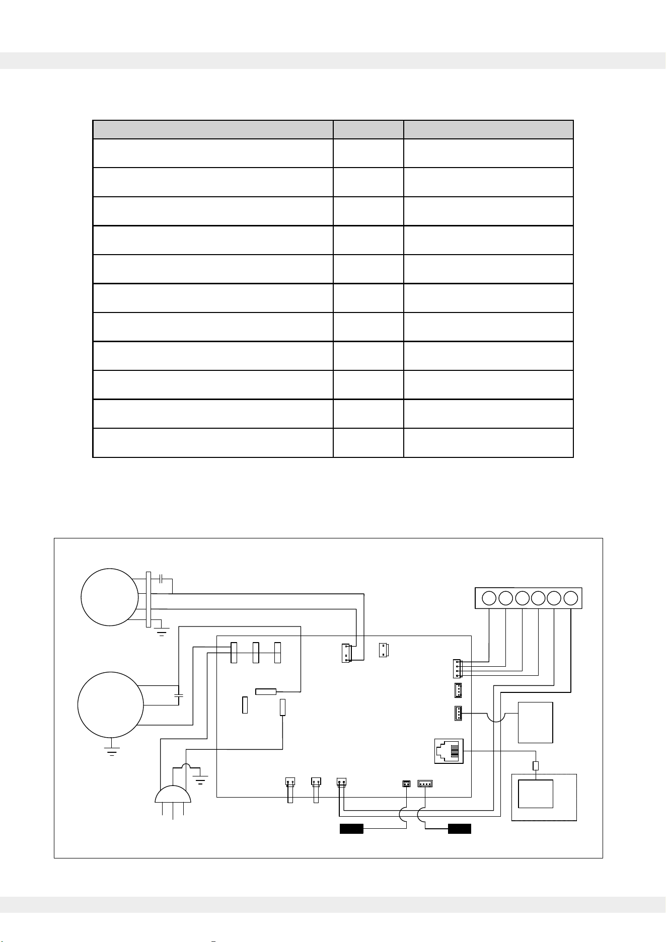
ii. QHD070AUDH26WH Dehumidifier Electrical Schematic
Description Unit Value
VInput Power Supply 110/120
HzFrequency 60
ARated Current 6.6
W 750Input Power
Pints/Day 70Dehumidification Capacity (80°F/60%RH)
-Filter Type 304 Grade Stainless Steel
ftPower Cord Length 10.6
Hose Length ft 6
Net Weight lbs 55
in.Machine Dimensions (WDH)
-/oz.Refrigerant Type/Amount
12-5/8 x 27-3/4 x 11
R32 / 9.9
AC-L
HI
Comp
LOW FULL1
PT
Temp/RH1
MODBUS
Temp/RH2
Dhum
R
Fan
C
AC-N
DISP
③ ②
①⑥ ⑤ ④
C
FAN
R
DEHUM
FLOAT
FLOAT
Compressor
S
C
R
Fan
POWER CORD
Air Inlet Temperature
and Humidity Sensor
Float Switch
Low
Pressure
Connector
Display
Board
External
control
RJ12
Connector
N L
PE
Options
CAP1
CAP2
115V/60Hz
Defrost Sensor
Circuit Diagram
N
Lo
Hi
Fan
Pump
Pump
N
Control Board
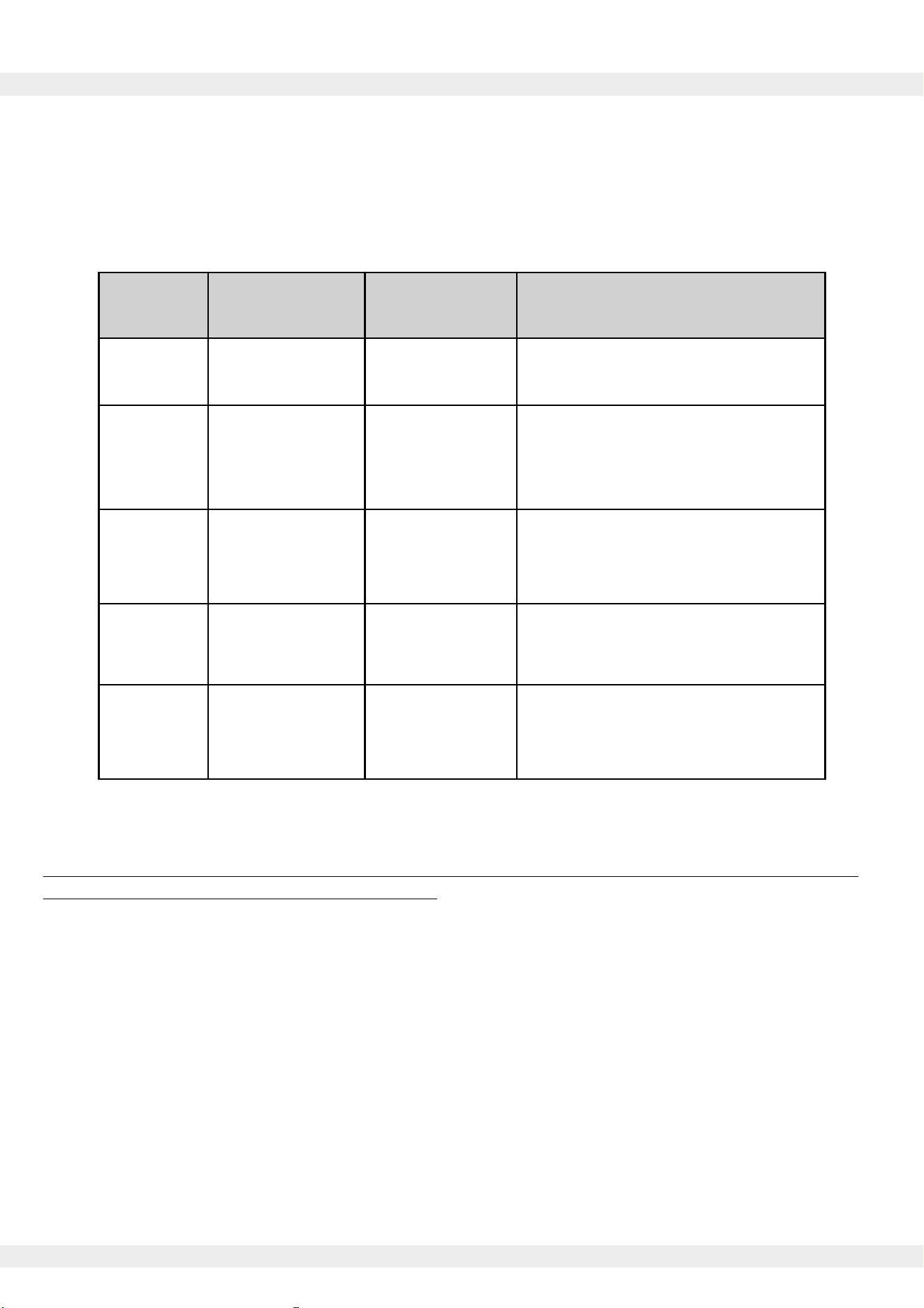
Fault types are divided into performance faults and safety faults. Performance faults allow for the
machine to be continue operation once resolved, but safety faults require the machine to be shut
down and restarted once the fault is eliminated.
If multiple faults occur simultaneously, they will be displayed in the order of fault codes.
IMPORTANT:
Before performing any disassembly or internal inspection, ensure that the system is unplugged or
that the main power to the system is turned off.
11. Troubleshooting
8
Error Code
System
Fault Description
Response
E0
Suggested Resolution
Communication
Failure
Alarm +
Shutdown
E1
Humidity Sensor
Fault
Inspect communication cable and
reconnect or replace if necessary
Auto-switch
to continuous
dehumidification
mode
E2
Temperature
Sensor Fault
Error Display
Only
Confirm that the temperature and
humidity sensors are securely
connected, and reconnect or
replace if necessary
E3
Water Reservoir
Full Alarm
Enter Standby
Mode
Confirm that the temperature
sensor is securely connected,
and reconnect or replace if
necessary
E4
Check for clogged drainage lines or
repair/replace the water pump
Coil Temperature
Sensor Fault
Enter Standby
Mode
Confirm that the coil temperature
sensor is securely connected,
and reconnect or replace if
necessary
This appliance contains refrigerant and other potentially hazardous materials. When disposing of
this appliance, the law requires special collection and treatment. Do not dispose of this product
as household waste or unsorted municipal waste.
When disposing of this appliance, you have the following options:
• Dispose of the appliance at a designated municipal electronic waste collection facility.
• When buying a new appliance, the retailer takes back the old appliance free of charge.
• The manufacturer takes back the old appliance free of charge.
• Sell the appliance to certified scrap metal dealers.
9
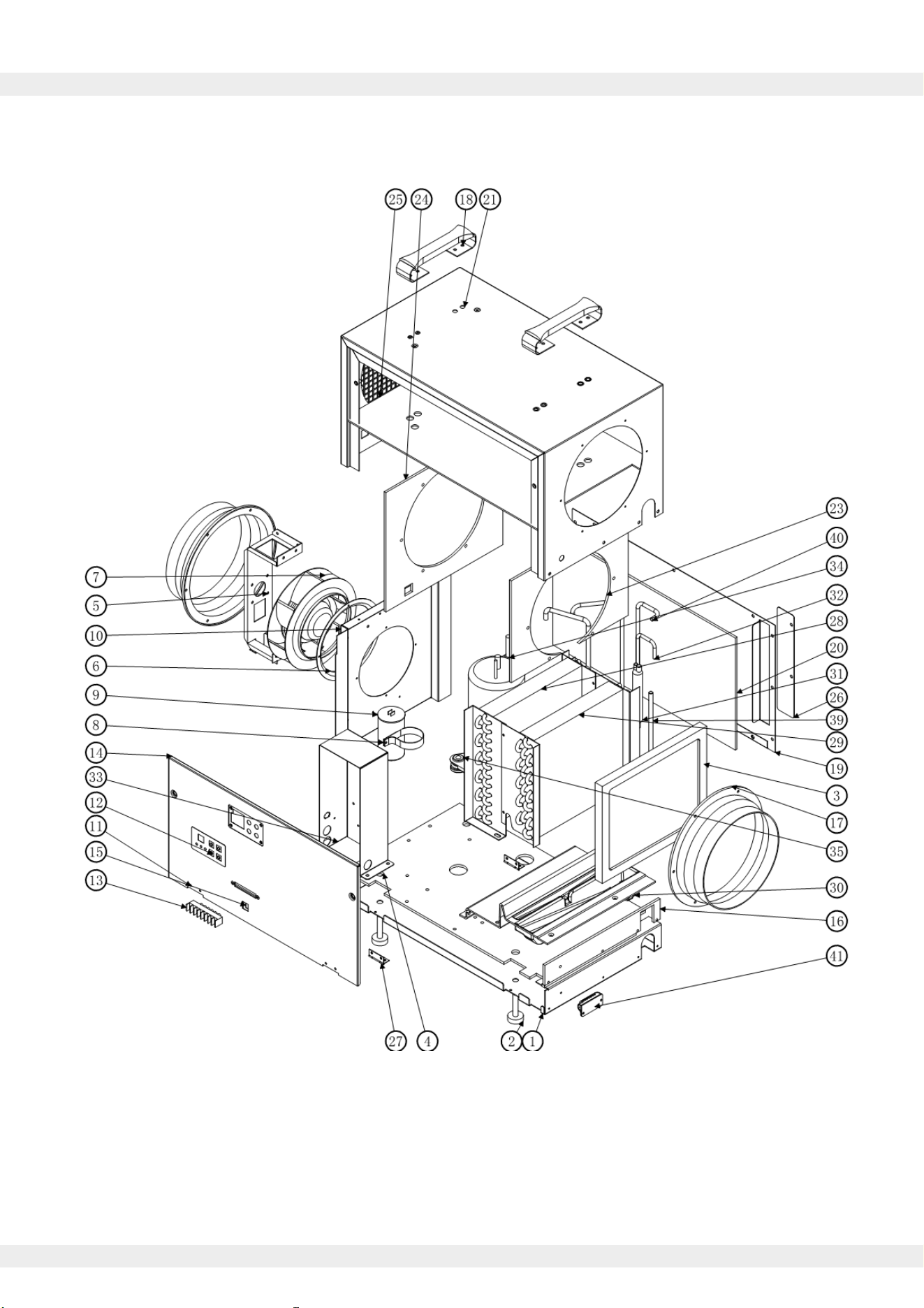
12. Exploded Parts Diagram
See Page 10 for the reference table of internal components.
10
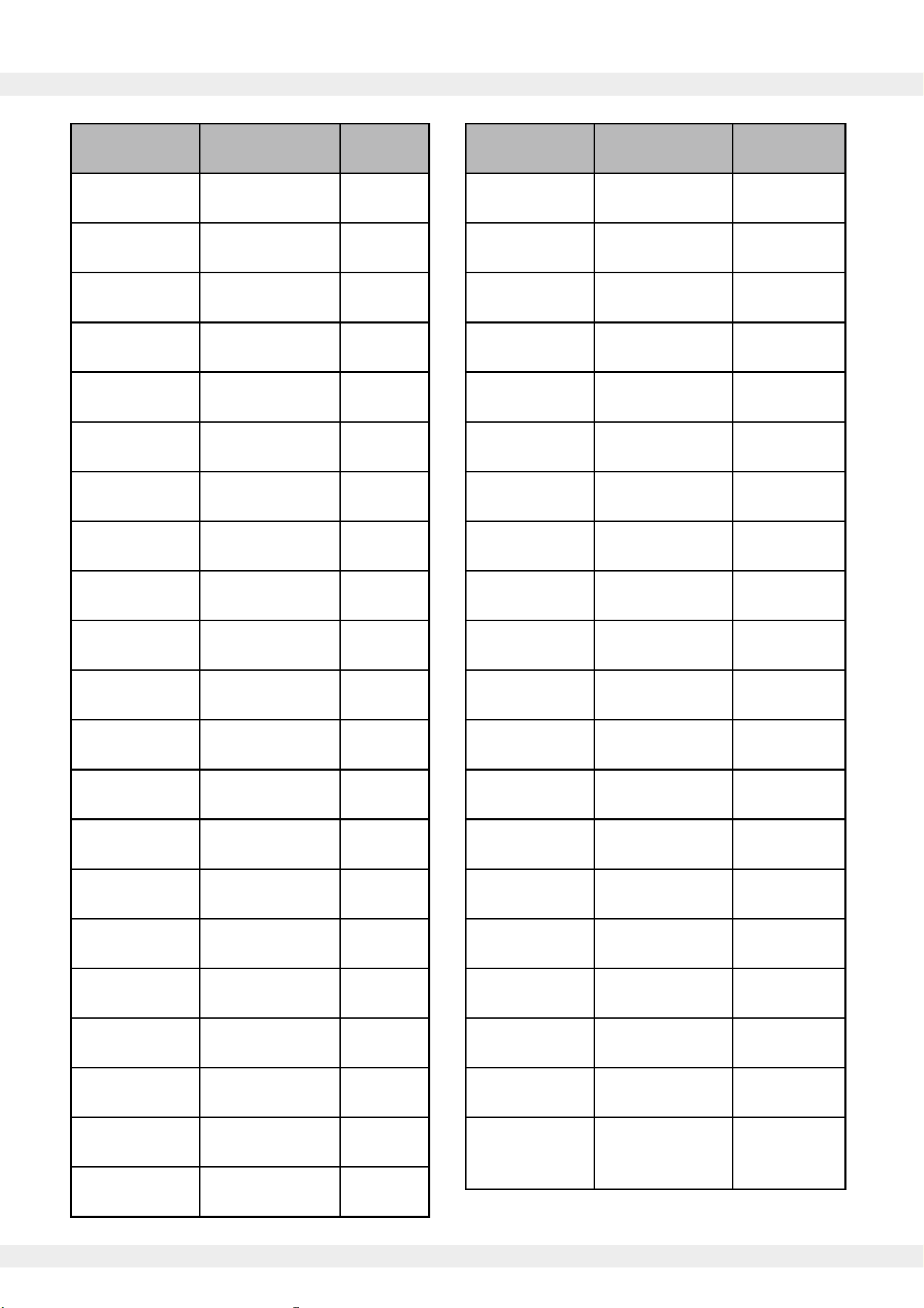
12. Exploded Parts Diagram (continued)
Item Number Part Name Quantity
1 1Chassis
2 Foot 4
3 Filter 1
4 1
5
Chassis Paste
Fan
Bracket
1
6 Air Guide 1
7 Fan 1
8 1
9 Capacitor Hoop
Compressor
Capacitor
1
10 1Middle Bracket
11 1Front Plate
12 1Interface
13 1
14
Terminal Block
1
15
Front Panel
Adhesive
1
16
Adapter
Mounting Plate
Chassis
1
Adhesive
17 2
Handles
8” Air Outlet
18 2
19 1
20
Rear Panel
Rear Panel
1
Adhesive
21 1Shell
Item Number Part Name Quantity
22 1
23
Filter Mesh
Holder
Airflow
1
Adhesive
24
Air Inlet
1
Adhesive
25
Shell
1
Adhesive
26
Filter
1
Baffle
27 2
28
1-1/2” Hinge
Condenser 1
29 Evaporator 1
30 1Drain Pan
31 1Filter Drier
32
Liquid
1
33
Outlet Pipe
1
34
Electrical Box
1Compressor
35 3
36
Compressor
Feet
1
37
Return Vent 1
1
38
Return Vent 2
1Tee Pipe
39 1
40
Low Pressure
Pipe
1
41
High Pressure
Pipe
1
Temperature
and Humidity
Sensor

The design and specifications of this product are subject to change without prior notice
as development continues. Consult with the sales agency or manufacturer for details.
Refer to the equipment nameplate for all other applicable specifications.
is a registered trademark of Parker Davis HVAC International.
Parker Davis HVAC International
7290 NW 77th Ct., Miami, FL 33166 - USA
Tel : (305) 513-4488
Fax : (305) 513-4499
E-mail : info@pd-hvac.com
Website : www.pd-hvac.com
Pioneer product line, parts, and supplies are
available online for convenient ordering at:
www.highseer.com
www.pioneerminisplit.com
Scan the below code to visit our support page
where you can find more installation materials:
Copyright 2024, Parker Davis HVAC International, Inc., All rights reserved.