
Installation Instructions
& Owner's Manual
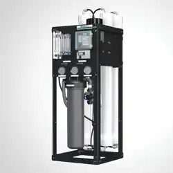
Commercial
RO Systems
CRO Series Reverse Osmosis Membrane Systems
aosmith.com/commercialwatertreatment

System Requirements and Operation Guidelines .................... 2
(Installation Instructions, Plumbing Connections, Electrical Connections)
Installation and Startup Checklist ................................ 4
Membrane Specifications ....................................... 5
System Identification ........................................... 6
Startup Procedures ............................................ 7
Operation and Maintenance ..................................... 8
(Changing the Pre-filter, Membrane Installation, Removal and Replacement)
Troubleshooting Guide ........................................ 10
Electrical Drawings ........................................... 11
Membrane Temperature Correction Chart. . . . . . . . . . . . . . . . . . . . . . . . . 12
System Warranty ............................................. 13
PLEASE READ THE ENTIRE MANUAL BEFORE PROCEEDING WITH THE
INSTALLATION AND STARTUP. YOUR FAILURE TO FOLLOW ANY INSTRUCTIONS
OR OPERATING PARAMETERS MAY LEAD TO THE PRODUCT’S FAILURE, WHICH
CAN CAUSE PROPERTY DAMAGE AND/OR PERSONAL INJURY.
• DO NOT USE WHERE THE WATER IS MICRO-BIOLOGICALLY UNSAFE OR OF UNKNOWN QUALITY WITHOUT
ADEQUATE DISINFECTION BEFORE OR AFTER THE SYSTEM.
• PRETREATMENT MUST BE SUFFICIENT TO ELIMINATE CHEMICALS THAT WOULD ATTACK THE MEMBRANE
MATERIALS.
• ALWAYS TURN OFF THE UNIT, SHUT OFF THE FEED WATER, AND DISCONNECT THE ELECTRICAL POWER
WHEN WORKING ON THE UNIT.
• NEVER ALLOW THE PUMP TO RUN DRY.
• NEVER START THE PUMP WITH THE CONCENTRATE VALVE CLOSED.
• NEVER ALLOW THE UNIT TO FREEZE OR OPERATE WITH A FEED WATER TEMPERATURE ABOVE 100°F.
Your A. O. Smith Commercial RO Series is a precision built, high quality product. These units will
deliver quality drinking water for many years to come, when installed and operated properly.
Please study this manual carefully and understand the cautions and notes before installing. This
manual should be kept for future reference. If you have any questions regarding your system,
contact your local dealer or the manufacturer at the following:
1900 Prospect Court • Appleton, WI 54914
Phone: 920-739-9401 • Fax: 920-739-9406
Table of Contents

3
INSTALLATION INSTRUCTIONS:
PLUMBING CONNECTIONS:
ELECTRICAL CONNECTIONS:
For the installer, the following must be adhered to:
• Proper pretreatment must be determined and installed prior to the RO system.
• The water supply and pretreatment equipment should be sufficient to provide a minimum of
45 psi at the maximum feed flow.
• Responsibility for meeting local electrical and plumbing codes lies with the owner/operator.
• Install indoors in an area protected from freezing. Space allowances for the removal of the
membranes from the pressure vessels should be provided.
NOTE: It is the responsibility of the end user to ensure that the installation is done according to local
codes and regulations.
1. Connect the pre-treated feed water line to the inlet solenoid valve. A feed water shutoff valve
should be located within 10 feet of the system.
2. Temporarily connect the product water outlet to a drain. The product outlet is located on the
back top of the permeate flow meter.
3. Connect the concentrate water outlet to a drain. The concentrate outlet is located on the back top
of the concentrate flow meter. The concentrate drain line should never be restricted. An air gap
must be located between the end of the drain line and the drain. The use of a standpipe or other
open drain satisfies most state and local codes and allows for visual inspection and sampling.
NOTE: It is the responsibility of the end user to ensure that the installation is done according to local
codes and regulations.
1. Make sure the ON/OFF switch on the front panel is in the “OFF” position.
2. Wire the supplied 110V or 220 volt cord (dependent on system being installed) to a junction
box power supply with a 20 amp breaker following local electrical codes.
Table of Contents System Requirements & Operation

4
STARTUP INSTALL/CONDITIONS
Installation Date: __________________________________
Installer Name: ___________________________________
Site of Install: _____________________________________
_________________________________________________
CRO System Model: _______________________________
Water Source: ____________________________________
_________________________________________________
Pre-treatment Installed: ❏ yes ❏no
If yes, explain: ______________________________________
FEED WATER ANALYSIS
TDS: Design _______________ Startup ___________
Turbidity: ____________________________________
Total Iron: ___________________________________
Chlorine: ____________________________________
Hardness: ___________________________________
Feed Water Temp: ____________________________
Pre-filter cartridge model: ______________________
Starting pre-filter inlet pressure:
_________________
• Pressure at startup: ________________________
FLOW METER READINGS
• Concentrate Design _______Startup _______
• Recycle Design _______Startup _______
• Permeate Design _______Startup _______
_________________________________________________
(Installer signature)
_________________________________________________
(date)
INSTALLATION CHECKLIST
Installation Address: _______________________________
_________________________________________________
❏Pre-treatment is installed and is flushed and working.
❏Installation location allows access to membrane(s).
❏Listed components and fittings are present.
❏Loose components assembled to system.
❏Membranes and pre-filter installed.
❏System securely in place.
❏Plumbing connections are complete.
❏Initial flush without leaks.
❏
Electrical power connected, single phase. ___Volts ___Hz
❏System sanitized.
❏Controller display working.
❏Proper operation is verified.
❏All checks above have been completed.
INSTALLATION NOTES
_________________________________________________
_________________________________________________
_________________________________________________
_________________________________________________
_________________________________________________
_________________________________________________
_________________________________________________
_________________________________________________
_________________________________________________
_________________________________________________
_________________________________________________
Please use the supplied checklists below to record the initial system hardware and site install conditions.
Keep this copy for future reference. If you have additional systems to install, make a copy of this form first.
Installation & Start-up Checklist
5
OPERATING LIMITS:
Membrane Type ..................................Polyamide Thin-Film Composite
Maximum Operating Temperature ......................100° F (38° C)
Maximum Operating Pressure .........................225 psi (15.5 bar) System Limits
pH Range, Continuous Operation* .....................2–11
pH Range, Short Term Cleaning (30 min) .................1–13
Maximum Feed Silt Density Index ......................5
Chlorine Tolerance.................................0 ppm
*Maximum temperature for continuous operations above pH 10 is 95° F (35° C)
Part Number Description
Applied Pressure psi
(bar)
Permeate Flow
Rate gpd (m
3
/d)
Nominal Salt
Rejection (%)
Membrane Quantities per GPD
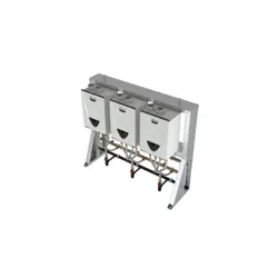
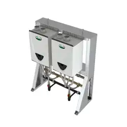
200387 HF4 – 2521 100 (6.89) 400 (1.51) 99.0
500 GPD - 2 membranes
1,000 GPD - 3 membranes
500–1,000 GPD HF4 Membrane - Product Specifications
Under certain conditions, the presence of free chlorine and other oxidizing agents will cause premature membrane failure. Since oxidation damage is
not covered under warranty, the manufacturer recommends removing residual free chlorine by pretreatment prior to membrane exposure. Wet tested
membrane elements must be kept sealed and moist when in storage. Drying out may occur and damage the membrane permanently. Prevent elements
from freezing or being exposed to direct sunlight. Wet tested elements are vacuum sealed in a polyethylene bag containing M100 Membrane Preservation
and then packaged in a cardboard box. Discard the permeate for the first 24 hours of operation. The permeate flow (product water flow) varies with feed
water temperature. For membrane warranty information, please contact the manufacturer.
The manufacturer believes the information and data contained herein to be accurate and useful. The information and data are offered in good faith,
but without guarantee, as conditions and methods of use of products are beyond the manufacturer’s control. The manufacturer assumes no liability
for results obtained or damages incurred through the application of the presented information and data. It is the user’s responsibility to determine the
appropriateness of these products for the user’s specific end uses.
¾” (19.05 mm) 2.4” (60.96 mm)
1.1”
(28
mm)
21” (533.4 mm)
¾” (19.05 mm) 3.95” (100.3 mm)
1.1”
(28
mm)
40” (1016 mm)
Part Number Description
Applied Pressure
psi (bar)
Permeate Flow
Rate PSI (gpd)
Applied Pressure
psi (bar)
Permeate Flow
Rate GPD (m³/d)
Nominal Salt
Rejection (%)
Membrane Quantities per GPD
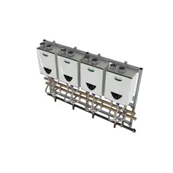
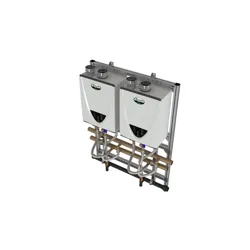
200394 HF5 – 4040 80 (5.52) 2500 (9.46) 100 (6.89) 3000 (11.36) 98.5
2,000 GPD - 1 membrane
4,000 GPD - 2 membranes
2,000–8,000 GPD HF5 Membrane - Product Specifications
6,000 GPD - 3 membranes
8,000 GPD - 4 membranes
Installation & Start-up Checklist
500-8000 GPD – Membrane Specifications
6
Item Number Description Part Number Model
1 Pump, Multi-Stage, 3/4 HP, 110/220V, 1PH, C1, GOULDS 100394022 500-4000
1 Pump, Multi-Stage, 1.5 HP, 110/220V, 1PH, C1, GOULDS 100394021 6000-8000
2 Membrane, HF4, 2521, Dry (see page 5 for qty. requirements) 200387 500-1000
2 Membrane, HF5, 4040, Dry (see page 5 for qty. requirements) 200394 2000-8000
2 Upgrade Kit, 2521, includes housing, membrane, and end caps 207881 500-1000
2 Upgrade Kit, 4040, includes housing, membrane, and end caps 207842 2000-4000
3 Switch, Pressure, Low, N/O, 15-30 psi, 1/4” FNPT 200906 500-8000
4 Kit, Valve, Solenoid, 2-way, Composite, 120V, 3/4” FNPT, ASCO 210462 500-4000
4 Kit, Valve, Solenoid, 2-way, Composite, 220V, 3/4” FNPT, ASCO 210463 500-4000
5 Cartridge, Sediment, Polypro, 4.5” x 20”, 5 MIC, SDC-45-2005 100243053 500-8000
6 O-Ring, Housing, Filter, Single, 4.5”, Pentek 151122 500-8000
7 Meter, Flow, PM, 0.1-1 GPM, 1/2” MNPT x 1/2” MNPT 203849 500-1000
7 Meter, Flow, PM, 0.2-2 GPM, 1/2” MNPT x 1/2” MNPT 200897 2000
7 Meter, Flow, PM, 1-5 GPM, 1/2” MNPT x 1/2” MNPT 200898 4000-6000
7
Meter, Flow, PM, 1-5 GPM, 1/2” MNPT x 1/2” MNPT 200898
8000
Meter, Flow, PM, 1-10 GPM, 1” MNPT x 1” MNPT 200899
8 Valve, Needle, SS 316L, 1/4” FNPT 201004 500-1000
8 Valve, Needle, SS 316L, 1/2” FNPT 201006 2000-8000
9 Gauge, PM, Gly Fill, 0-300 PSI/Bar, 2.5” Diameter MNPT 200904 500-8000
9 Gauge, PM, Gly Fill, 0-100 PSI/Bar, 2.5” Diameter MNPT 204165 500-8000
10 RO, HDM-2 TDS MONITOR, OEM 243088 500-8000
11 Valve, Globe, SS, 3/4” FNPT 200994 500-8000
12 Controller, RO, On/Off, C21 207818 500-8000
12 Controller, 2A, C23 207748 500-8000
13 End Cap, 2.5” 208904 500-1000
Not shown O-Ring, EDPM, 2.5” 208909 500-1000
13 End Cap, 4” 209824 2000-8000
Not shown O-Ring, EDPM, 4”, FRP-300E 205896 2000-8000
Not shown 1/2” O-Ring, Membrane, 2.5” End Cap 208912 500-1000
Not shown Black Check Valve, PP, Glass-filled 200965 500-8000
Models: CRO 500-8000
TDS MONITOR
13
System Identification

7
PURGE:
1. Verify incoming pressure is between 40 and 70 psi.
2. Verify that the pretreatment equipment is installed and working properly. Pre-filtration must be
flushed and sediment free.
3. Direct permeate water to drain temporarily.
4. Verify that the FLUSH/OFF/ON rocker switch is in the “OFF” position.
5. Fully open the concentrate valve (counter clockwise).
6. Fully close the concentrate recycle valve clockwise.
7. Fully open the globe valve on pump end (counter clockwise).
8. Slowly turn on feed water supply.
9. Re-verify incoming pressure is between 40 and 70 psi.
10. Push rocker switch to “FLUSH” mode to open solenoid (this is a momentary position).
11. Allow the unit to pressurize completely and check for any leaks, purge all the air out of the
system and observe the concentrate flow meter for air to be expelled. Return rocker switch to
“OFF” position.
12. Verify incoming pressure is between 40 and 70 psi on filter in gauge. Pressure reducing valve
will be required if pressure is greater than 70.
INITIAL STARTUP:
1. Fully close globe valve on pump end (clockwise) then open one full revolution
(counter clockwise).
2
. Turn the rocker switch on the front panel to the “ON” position with the indicating green light lit.
3. System pump should turn on and boost pressure to the system.
4. Allow the unit to run for 30-60 minutes to flush the preservative from the membrane(s).
NOTE: Do not exceed 200 psi on the pump pressure gauge.
5. Adjust the concentrate, concentrate recycle valve, and globe valves until the desired flows
are achieved.
6. Allow the product water to flow to drain for an additional 30-60 minutes.
7. Test and verify unit performance. Turn off the system and re-direct the product line to the point
of use.
8. Restart the system and check for system leaks.
System Identification Start-up Procedures

8
The reverse osmosis process causes the concentration of impurities. The impurities may precipitate (come
out of solution) when their concentration reaches saturation levels.
NOTE: Precipitation can scale or foul membranes and must be prevented.
Check your feed water chemistry and pre-treat the water and/or reduce the system’s recovery as required.
If necessary, consult with your local dealer or distributor.
PRE-FILTER PRESSURE GAUGES:
These gauges measure the feed water pressure when it enters and exits the pre-filters. A pressure
differential of 10-15 psi or more on the two pressure gauges indicates that the pre-filter requires servicing.
For example, if the inlet pressure is 40 psi, the filter should be changed when the outlet pressure is 30 psi
or below. Failure to maintain filter will result in system damages.
CHANGING THE PRE-FILTER:
WARNING: All pressure gauges must be read zero before proceeding.
Before attempting, disconnect the power from the system and bleed all
water pressure from the system.
The system comes with a standard 5 Micron Sediment Depth Filter that is located inside the filter housing.
1. To remove filter, turn the filter housing counterclockwise using the filter wrench supplied with
system.
2. Once removed, replace sediment cartridge with similar size 5 micron sediment filter. Dispose
of old filter properly. Check o-ring located at top of filter housing sump and re-lube or replace
if necessary before re-installing on system. Re-install housing, turn hand tight (clockwise) and
check for leaks after system is turned back on.
MEMBRANE INSTALLATION, REMOVAL AND REPLACEMENT:
Installing and replacing membranes in the pressure vessels is an easy process if you have the proper
information and tools at hand. Please refer to the following instructions when removing and replacing
membrane elements:
WARNING: All pressure gauges must be read zero before proceeding.
Before attempting, disconnect the power from the system and bleed all
water pressure from the system.
1. Remove the end plugs from the top of the pressure vessels. This is done by removing the two
half-moon retaining disks using a #5 Allen wrench; the end plugs should then freely slide out of
the pressure vessel.
2. Remove the replacement membrane element(s) from the shipping box; the membrane(s) should
be contained within a plastic oxygen barrier bag.
NOTE: Wear gloves for the following steps in order not to contaminate the membrane.
3. Cut the bag open as close as possible to the seal at one end of the bag, so the bag may be
re-used if necessary.
Operation & Maintenance
9
4. Remove membrane from bag. Make sure that all parts of the membrane are clean and free
from dirt. Examine the brine seal and permeate tube for nicks or cuts. Replace the o-rings or
brine seal if damaged.
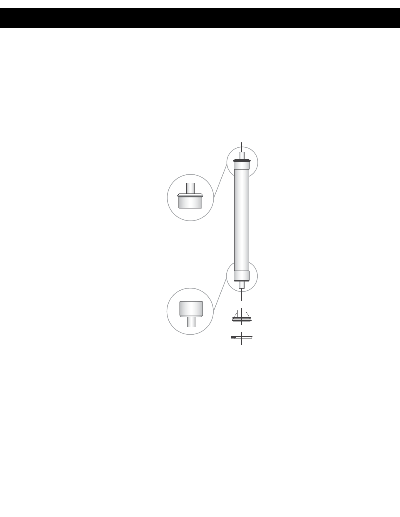
5. Load membranes into pressure vessels according to the concentrate flow direction. Note the
position of the brine seal placement on the membrane. Each housing has an arrow indicating
the direction of flow for that housing. The brine seal must be at the water inlet of the housing.
6. Use Dow #7 silicone grease on the o-rings and brine seal before installing the membrane.
7. Install the new membrane in direction as shown in diagram:
8.
Once membrane has been fully inserted into vessel, re-install the black end plug, white snap ring,
and yellow locking clip. (Ensure the white snap ring is fully seated all the way around the end plug.)
9. Change is complete.
NO SEAL
SEAL
Operation & Maintenance Operation & Maintenance
10
1. Low inlet pressure
A. Low supply pressure A. Increase inlet pressure
B. Cartridge filters plugged B. Change filters
C. Solenoid valve malfunction C. Replace solenoid valve and/or coil
D. Leaks D. Fix any visible leaks
2. Low permeate flow
A. Low inlet flow A. Adjust concentrate valve
B. Cold feed water B. See temperature correction sheet (page 12)
C. Low operating pressure C. See low inlet pressure
D. Defective membrane brine seal D. Inspect and/or replace brine seal
E. Fouled or scaled membrane E. Clean membranes
3. High permeate flow
A. Damaged product tube o-rings A. Inspect and/or replace o-rings
B. Damaged or oxidized membranes B. Replace membrane
C. Exceeding maximum feed water temperature C. See temperature correction sheet (page 12)
4. Poor permeate quality
A. Low operating pressure A. See low inlet pressure
B. Damaged product tube o-rings B. Inspect and/or replace o-rings
C. Damaged or oxidized membranes C. Replace membrane
5. Membrane fouling
A. Metal oxide fouling
A. Improve pretreatment for colloid removal.
Clean with acid cleaners.
B. Colloidal fouling
B. Optimize pretreatment for colloid removal.
Clean with high pH anionic cleaners.
C. Scaling (CaSO4, CaSO3, BaSO4, SiO2)
C. Increase acid addition and antiscalent dosage
for CaVO3 and CaCO4. Reduces recovery.
Clean with acid cleaners.
D. Biological fouling
D. Shock dosage of Sodium Bisulfate. Continuous
feed of Sodium Bisulfate at reduced pH.
Chlorination and de-chlorination. Replace
cartridge filters.
E. Organic fouling
E. Activated carbon or other pretreatment. Clean
with high pH cleaner.
F. Chlorine oxidation
F. Check chlorine feed equipment and
de-chlorination system.
G. Abrasion of membrane by crystalline material
G. Improve pretreatment. Check all filters for media
leakage.
Troubleshooting Guide

11
Troubleshooting Guide
Electrial Drawings – 120 Volt

13
12
Membrane Temperature Correction

13
Membrane Temperature Correction
A. O. Smith Commercial Limited Warranty
WHO IS COVERED
This limited warranty is provided by A. O. Smith and applies only to the original owner who purchased and installed the A. O. Smith product for
use at the original installa on site. This warranty is non-transferable.
WHAT IS COVERED
This warranty covers defects in materials or workmanship in your A. O. Smith product when properly installed, used under normal opera ng
condi ons, and maintained according to A. O. Smith guidelines and local plumbing codes.
WARRANTY COVERAGE PERIODS
All warranty coverage periods run from the date of purchase, or 60 days a er the date of manufacture if the purchase date cannot be verifi ed.
For a period of ONE YEAR: The en re reverse osmosis water system, including the reverse osmosis modules, with the excep on of the
expendable fi lter cartridges used in the system.
WHAT A. O. SMITH WILL DO
If a component is found defec ve during its warranty period, A. O. Smith will repair or replace the defec ve part at its discre on with an iden cal
part or a comparable part if an iden cal replacement is not available. The owner is responsible for freight charges from the factory and local
dealer service or labor fees. The warranty period for any replacement will run for the balance of the original warranty period.
WHAT A. O. SMITH WILL NOT DO
A. O. Smith will not pay for labor to remove or reinstall parts, shipping damage, water damage resul ng from system failure, dealer trip charges,
unauthorized service, damage caused by failure to follow installa on instruc ons, or replacement fi lters, media, or rou ne maintenance.
WHAT IS NOT COVERED
1. This warranty does not cover: damage caused by accident, misuse, neglect, fi re, fl ood, freezing, or other acts of God, improper
installa on, altera on, vacuum damage, chemicals, opera on outside specifi ca ons, cosme c issues, non-A. O. Smith parts,
installa on costs, improper plumbing connec ons, lack of maintenance, use with water that is microbiologically unsafe, loss of use,
property damage, incidental or consequen al damages, freight, or water damage. A. O. Smith disclaims all implied warran es to the
fullest extent permi ed by law.
2. Except when specifi cally prohibited by the applicable state law, the Owner, and not the Manufacturer, shall be liable for and shall pay
for all charges for labor or other expenses incurred in the removal, repair or replacement of any component part(s) claimed to be
defec ve or any expense incurred to remedy any defect in the product. Such charges may include, but are not necessarily limited to:
a. All freight, shipping, handling and delivery costs of forwarding a new component or replacement part(s) to the owner.
b. All costs necessary or incidental in removing the defec ve component part(s) and installing a new component part(s).
c. Any material required to complete, and/or permits required for, installa on of a new component or replacement part(s).
d. All costs necessary or incidental in returning the defec ve component part(s) to a loca on designated by the Manufacturer.
e. This warranty provides specifi c legal rights and limita ons, but you may have other rights under applicable state law.
OWNER RESPONSIBILITIES
Owners must install and operate the system per A. O. Smith specifi ca ons, comply with local codes, prevent freezing or vacuum damage,
operate within pressure/temperature limits, replace media/fi lters as required, use only approved components, and retain proof of purchase and
installa on date. Either proof of purchase from an authorized dealer or proof of serial number, along with proof of proper installa on, will be
required to obtain warranty coverage.
HOW TO OBTAIN SERVICE
If service is required, contact your installa on dealer or an authorized A. O. Smith dealer. If unavailable, ship the defec ve component (freight
prepaid) to: A. O. Smith, 1000 Prospect Ct., Appleton, WI 54914. A. O. Smith will return repaired or replaced parts freight collect. Registra on is
not required to be covered by this warranty.
LIMITATION OF REMEDIES
The owner’s sole remedy is repair or replacement of defec ve parts. A. O. Smith is not liable for incidental, consequen al, water, or property
damages. Some states do not allow such limita ons; in such states, these may not apply.
STATE LAW RIGHTS
This warranty provides specifi c legal rights; addi onal rights may vary by state.
© 2026 A. O. Smith, Inc. All rights reserved.

14
NOTES:

15
NOTES:

© 2014 A. O. Smith, Inc. All rights reserved.
REV0326 - 100403302 - 2000857057
1900 Prospect Court • Appleton, WI 54914
Phone: 920-739-9401 • Fax: 920-739-9406