Page 1For technical questions, please call 1-888-866-5797.Item 96406
Owner’s Manual & Safety Instructions
Save This Manual Keep this manual for the safety warnings and precautions, assembly,
operating, inspection, maintenance and cleaning procedures. Write the product’s serial number in the
back of the manual near the assembly diagram (or month and year of purchase if product has no number).
Keep this manual and the receipt in a safe and dry place for future reference. 23d
When unpacking, make sure that the product is intact
and undamaged. If any parts are missing or broken,
please call 1-888-866-5797 as soon as possible.
Copyright
©
2007 by Harbor Freight Tools
®
. All rights reserved.
No portion of this manual or any artwork contained herein may be reproduced in
any shape or form without the express written consent of Harbor Freight Tools.
Diagrams within this manual may not be drawn proportionally. Due to continuing
improvements, actual product may differ slightly from the product described herein.
Tools required for assembly and service may not be included.
Read this material before using this product.
Failure to do so can result in serious injury.
SAVE THIS MANUAL.
Visit our website at: http://www.harborfreight.com
Email our technical support at: [email protected]
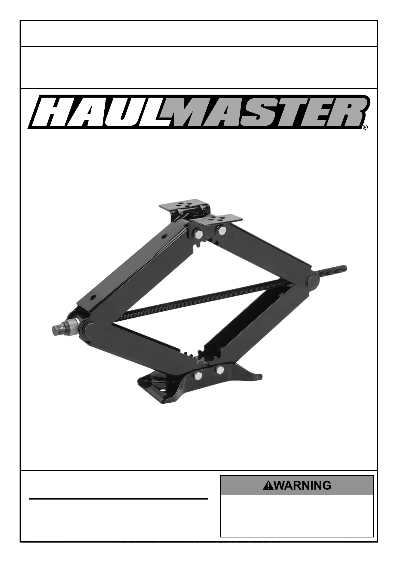
96406
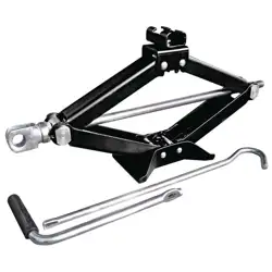
2.5 TON TRAILER/RV
SCISSOR STABILIZER
Page 2 For technical questions, please call 1-888-866-5797. Item 96406
Table of Contents
Safety ....................................................... 2
Specifications ........................................... 3
Setup ........................................................ 4
Operation .................................................. 5
Maintenance ............................................. 6
Parts List And Diagram ............................. 7
Warranty ................................................... 8
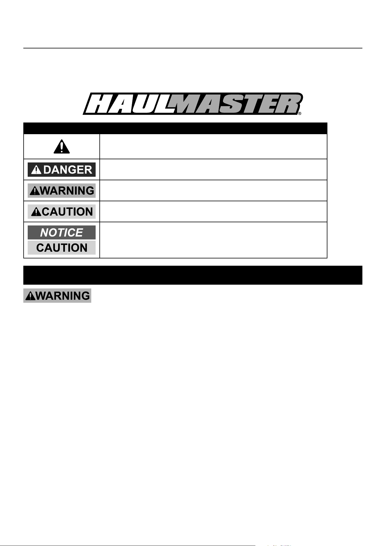
WARNING SYMBOLS AND DEFINITIONS
This is the safety alert symbol. It is used to alert you to
potential personal injury hazards. Obey all safety messages
that follow this symbol to avoid possible injury or death.
Indicates a hazardous situation which, if not avoided,
will result in death or serious injury.
Indicates a hazardous situation which, if not avoided,
could result in death or serious injury.
Indicates a hazardous situation which, if not avoided,
could result in minor or moderate injury.
Addresses practices not related to personal injury.
IMPORTANT SAFETY INSTRUCTIONS
READ AND UNDERSTAND ALL INSTRUCTIONS! Failure to follow all instructions listed
below may result in serious injury.
1. Study, understand, and follow all instructions
before operating this device.
2. Do not exceed rated capacity.
3. Use only on a hard, level surface
capable of supporting the load.
4. Failure to heed these markings may result in
personal injury and/or property damage.
5. Lift only on areas of the vehicle as
specified by the vehicle manufacturer.
6. No alterations shall be made to this product.
7. Only attachments and/or adapters supplied
by the manufacturer shall be used.
8. DO NOT USE THIS LEVELING STABILIZER
FOR LIFTING. Do not use to change tires.
9. Keep space around Stabilizer as uncluttered as
possible during use. Clutter can hinder smooth
operation and possibly cause accidents and/
or serious personal injury. Keep area well lit.
10. Keep out from under trailer or RV. Keep
hands away from scissor mechanism.
11. Wear ANSI-approved safety goggles and
heavy duty work gloves during use.
12. Install this Leveling Stabilizer in
accordance with DMV regulations.
13. Keep children away. Children must never be
allowed in the Leveling Stabilizer area. Do not
let them handle the Stabilizer at any time.
14. Use the right tool for the job. There are certain
applications for which this Leveling Stabilizer
was designed. It will do the job better and more
safely at the rate for which it was intended. Do not
modify this Stabilizer and do not use this Stabilizer
for a purpose for which it was not intended.
15. Dress properly. Do not wear loose clothing or
jewelry as they can be caught in moving parts.
Wear restrictive hair covering to contain long hair.
16. Do not overreach. Keep proper footing and
balance at all times. Do not reach over or
across a Leveling Stabilizer under a load.
17. Maintain tools with care. Keep tools clean
for better and safer performance. Follow
instructions for lubricating and changing
accessories. The handle must be kept clean,
dry, and free from oil and grease at all times.
Page 3For technical questions, please call 1-888-866-5797.Item 96406
18. Check for damaged parts. Before using any
tool, any part that appears damaged should be
carefully checked to determine that it will operate
properly and perform its intended function.
Check for alignment and binding of moving parts;
any broken parts or mounting fixtures; and any
other condition that may affect proper operation.
Any part that is damaged should be properly
repaired or replaced by a qualified technician.
19. Replacement parts and accessories. When
servicing, use only identical replacement parts. Use
of any other parts will void the warranty. Only use
accessories intended for use with this tool. Approved
accessories are available from Harbor Freight Tools.
20. Stay alert. Watch what you are doing, use common
sense. Do not operate any tool when you are tired.
21. Do not operate tool if under the influence of
alcohol or drugs. Read warning labels if taking
prescription medicine to determine if your judgment
or reflexes are impaired while taking drugs. If
there is any doubt, do not operate the tool.
22. Stand clear of the Leveling Stabilizer when
attempting to level any trailer or RV.
23. Never exceed the Stabilizer’s capacity of 5,000
lb. Check the trailer or RV’s manual to determine
the actual gross weight before attempting to level
it. This Stabilizer’s weight capacity is 5,000 lb.
only between 13-3/4" and 23-1/2"; the weight
capacity drastically reduces as the height
drops below this level. Do not apply a load
to this Stabilizer below 13-3/4" in height.
24. Never stand on the Stabilizer and never have people
or pets in the trailer or RV you are attempting to level.
25. Place the Leveling Stabilizer on a flat, level surface.
Only use this Stabilizer on a stable, clean, dry
surface that is capable of sustaining the weight
of the Stabilizer and the load it is stabilizing.
26. Stabilize the load. Ensure that the load
remains stable at all times. Do not move the
load while it is on the Leveling Stabilizer.
27. Block all of the wheels when leveling an RV or trailer.
28. Do not use this Leveling Stabilizer
for aircraft purposes.
29. Some RV sub-frames are not capable of handling
any additional forces beyond its intended design
strength to support the cabin weight. Contact
your RV manufacturer for the sub-frame strength
information before use of this Stabilizer.
30. The warnings, cautions, and instructions
discussed in this instruction manual cannot cover
all possible conditions and situations that may
occur. It must be understood by the operator
that common sense and caution are factors
which cannot be built into this product,
but must be supplied by the operator.
SAVE THESE INSTRUCTIONS.
Specifications
Stabilizer Construction 10 Gauge Sheet Steel Plate
Crank Handle Construction
and Dimensions
Steel Rod Rubber Grip and Attached Socket
25-3/4" L X 15/32" Diameter (5" Long
Rubber Handle and Grip)
Stabilizer Capacity 5000 lb. maximum capacity with height not less than 13-3/4"
Height Range 4-5/8" Minimum Height to 23-1/2" Maximum Height
Overall Dimensions
26-1/4" Total Length X 4-5/8" High X 6-3/4"
Wide (Collapsed for Storage)
Stabilizer Mounting
Bolt-On (see directions on page 5 of this manual)
Weld-On (see directions on page 5 of this manual)
Unmounted use is NOT recommended
Weight 14.35 lb. (Stabilizer Only)
Page 4 For technical questions, please call 1-888-866-5797. Item 96406
Setup - Before Use:
Note: For further information on parts
and assembly break-down, see the
diagram on page 7 of this manual.
Installation
WARNING! TO PREVENT SERIOUS INJURY: Do
not use this Leveling Stabilizer while unmounted.
WARNING! Before drilling holes, check for any
chassis components which may be inside the
frame. Look for electrical lines and wires, gas
tank, gas lines, water and holding tanks, generator
fuel lines and water heater lines. Make sure area
is clear of these components before drilling.
1. Park RV or Trailer on level ground. Prevent
the wheels from rolling by applying emergency
brake and wheel blocks (not included).
2. Check the following before
proceeding with the installation:
a. Attach Stabilizer to the frame of the
RV or Trailer using two c-clamps
(not included) or two vise grips (not
included). Close the Stabilizer using the
Handle Wrench (16) to check the frame
location. Make sure the Stabilizer will
clear any chassis components nearby.
b. Open the Stabilizer enough to touch
the ground. Recheck the location on
the frame and adjust if needed.
c. Once in place, apply enough pressure
between the ground and the Stabilizer to
ensure that it will not move during the rest of
the installation process. Remove the c-clamps
(not included) or vise grips (not included).
3. For Bolt-On Installation:
a. Hold the Stabilizer against the frame
and using the Mounting Brackets (9) as
a template, mark the locations of the
8 mounting holes on the RV or Trailer
frame. Remove the Stabilizer.
b. Use a center punch (not included)
and hammer (not included) to
mark the center of each hole.
c. Use a drill (not included) to make a pilot
hole 1/8". Then use a 5/16" drill bit (not
included) to complete each hole. Use
eight 3/8" tapping screws (not included)
with eight lock washers (not included)
to attach the Stabilizer to the frame.
4. For Weld-On Installation:
a. Hold the Stabilizer against the frame
and using the Mounting Brackets (9) as
a template, mark the locations of the 8
mounting holes on the RV or Trailer frame.
b. Weld at least four 1″ welds on the
Stabilizer Mounting Brackets (9)
when attaching to the frame.
Page 5For technical questions, please call 1-888-866-5797.Item 96406
Operating Instructions
Trailers, Travel Trailers and 5th Wheels
1. Park on level ground.
2. Level trailer (travel trailer, 5th wheel) front
and back with small carpenter’s level (not
included), or round bubble level (not included).
Place leveling blocks (not included) in front
of one tire on trailer. Slowly pull forward to
drive the trailer up onto the blocks. When
the trailer is level, stop and block all tires to
keep from rolling forward or backward.
3. Using Handle Wrench (16) lower the Stabilizer
on the lowest side first to get level. Use one
Stabilizer on each side for best results.
4. After Stabilizer makes firm contact with ground,
turn Handle Wrench (16) twice to insure
Stabilizer will not loosen from trailer during use.
Note: When RV or trailer will not be moved
for several days, periodically check Stabilizer
to be sure they have not worked loose.
Motor Homes
1. Park on level ground and level motor home
front and back (see step 2 in previous section).
2. Using Handle (16) lower Stabilizer on
opposite sides for stabilization (see
steps 3 and 4 in previous section).
Note: If motor home comes with factory
installed hydraulic levelers, the Leveling
Stabilizer can be used to provide additional
stabilization. Follow the directions for installation
found in this manual on pages 4 and 5.

Page 6 For technical questions, please call 1-888-866-5797. Item 96406
Maintenance
Procedures not specifically explained in this manual
must be performed only by a qualified technician.
TO PREVENT SERIOUS INJURY FROM TOOL FAILURE: Do not use damaged equipment.
If abnormal noise or vibration occurs, have the problem corrected before further use.
1. Periodically clean Stabilizer of any
dirt, grease, or debris.
2. Before each use, inspect the general condition
of the Stabilizer. Check for broken, cracked,
or bent parts, loose or missing parts, and any
condition that may affect the proper operation
of the product. Do not use damaged equipment.
Discard Stabilizer if damaged or deformed.
3. Periodically lubricate Screw Rod (4) Threads
with high quality light weight oil (not included).
PLEASE READ THE FOLLOWING CAREFULLY
THE MANUFACTURER AND/OR DISTRIBUTOR HAS PROVIDED THE PARTS DIAGRAM IN THIS MANUAL AS A
REFERENCE TOOL ONLY. NEITHER THE MANUFACTURER NOR DISTRIBUTOR MAKES ANY REPRESENTATION
OR WARRANTY OF ANY KIND TO THE BUYER THAT HE OR SHE IS QUALIFIED TO MAKE ANY REPAIRS TO THE
PRODUCT OR THAT HE OR SHE IS QUALIFIED TO REPLACE ANY PARTS OF THE PRODUCT. IN FACT, THE
MANUFACTURER AND/OR DISTRIBUTOR EXPRESSLY STATES THAT ALL REPAIRS AND PARTS REPLACEMENTS
SHOULD BE UNDERTAKEN BY CERTIFIED AND LICENSED TECHNICIANS AND NOT BY THE BUYER. THE BUYER
ASSUMES ALL RISK AND LIABILITY ARISING OUT OF HIS OR HER REPAIRS TO THE ORIGINAL PRODUCT OR
REPLACEMENT PARTS THERETO, OR ARISING OUT OF HIS OR HER INSTALLATION OF REPLACEMENT PARTS
THERETO.
Record Product’s Serial Number Here:
Note: If product has no serial number, record month
and year of purchase instead.
Note: Some parts are listed and shown for illustration purposes only, and are not available
individually as replacement parts. Specify UPC 193175459541 when ordering parts.
Page 7For technical questions, please call 1-888-866-5797.Item 96406
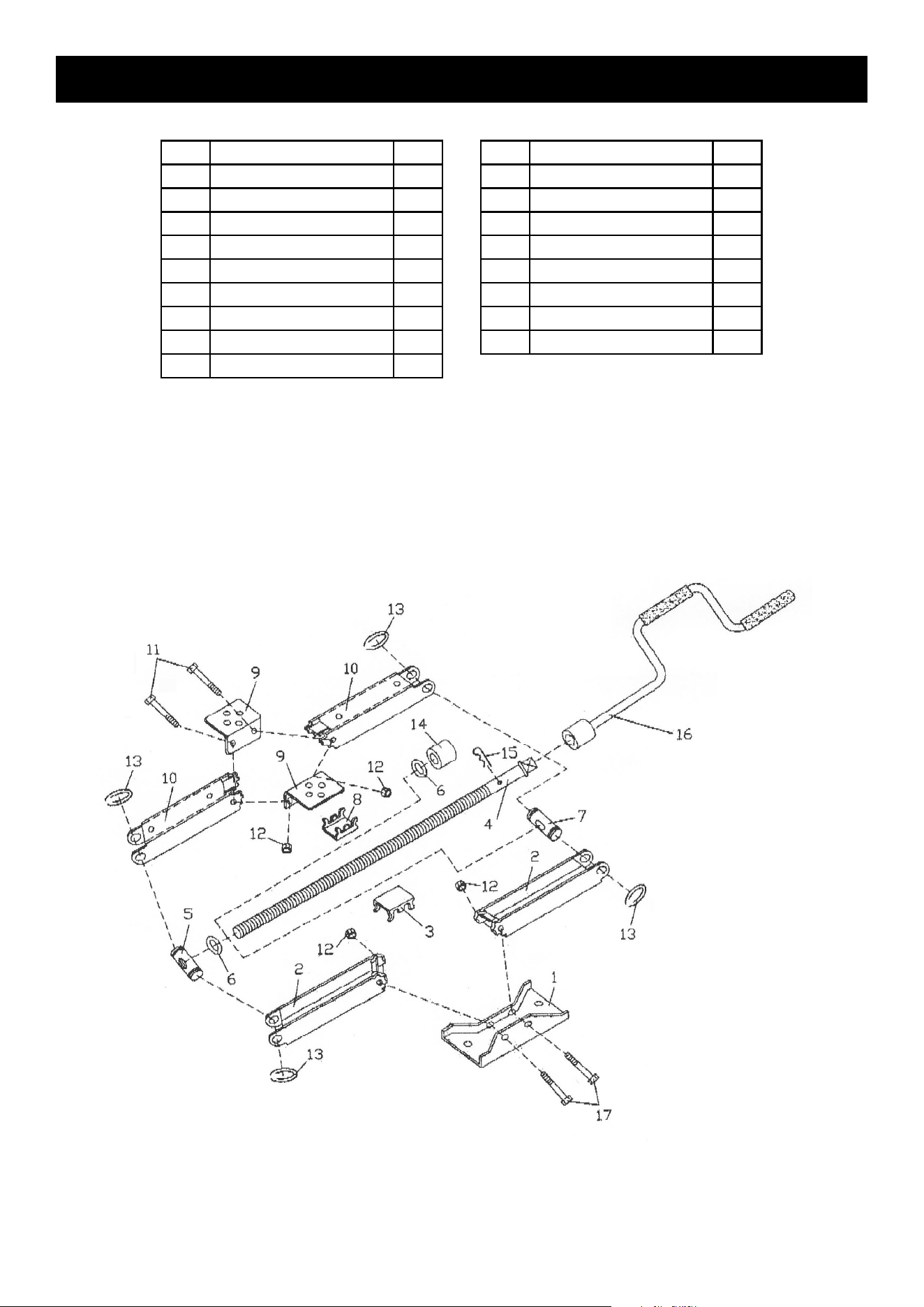
Parts List And Diagram
Part Description Qty
1 Base
1
2 Lower Stabilizing Arm
2
3 Lower Fixing Frame
1
4 Screw Rod
1
5 Axis with Thread
1
6 Flat Washer 16
2
7 Axis w/out Thread
1
8 Upper Fixing Frame
1
9 Mounting Brackets 2
Part Description Qty
10 Upper Stabilizing Arm 2
11 Hex Bolt M10 X 70 2
12 Lock Nut M10 4
13 Retaining Ring 4
14 Bearing 1
15 R-Clip 1
16 Handle Wrench 1
17 Hex Bolt M10 X 80 2

Limited 90 Day Warranty
Harbor Freight Tools Co. makes every effort to assure that its products meet high quality and durability standards,
and warrants to the original purchaser that this product is free from defects in materials and workmanship for the
period of 90 days from the date of purchase. This warranty does not apply to damage due directly or indirectly,
to misuse, abuse, negligence or accidents, repairs or alterations outside our facilities, criminal activity, improper
installation, normal wear and tear, or to lack of maintenance. We shall in no event be liable for death, injuries
to persons or property, or for incidental, contingent, special or consequential damages arising from the use of
our product. Some states do not allow the exclusion or limitation of incidental or consequential damages, so the
above limitation of exclusion may not apply to you. THIS WARRANTY IS EXPRESSLY IN LIEU OF ALL OTHER
WARRANTIES, EXPRESS OR IMPLIED, INCLUDING THE WARRANTIES OF MERCHANTABILITY AND FITNESS.
To take advantage of this warranty, the product or part must be returned to us with transportation charges
prepaid. Proof of purchase date and an explanation of the complaint must accompany the merchandise.
If our inspection verifies the defect, we will either repair or replace the product at our election or we may
elect to refund the purchase price if we cannot readily and quickly provide you with a replacement. We will
return repaired products at our expense, but if we determine there is no defect, or that the defect resulted
from causes not within the scope of our warranty, then you must bear the cost of returning the product.
This warranty gives you specific legal rights and you may also have other rights which vary from state to state.
26677 Agoura Road • Calabasas, CA 91302 • 1-888-866-5797