
Main Control Panel
Lochinvar, LLC 300 Maddox Simpson Parkway, Lebanon, Te nnessee 37090 ▪ (877) 737-2840 ▪ Lochinvar.com
Installation Manual
A Controller for Lochinvar Commercial Heat Pump Water Heaters
For Control Panels produced from 3/13/26 to: IM-MCP-NWS-L260303

Lochinvar, LLC 300 Maddox Simpson Parkway, Lebanon, Tennessee, 37090 ▪ (877).737.2840 ▪ Lochinvar.com
IM-MCP-NWS-L260303
2
Contents
Introduction ..............................................................3
Safety Information ................................................... 3
Precautions .............................................................3
Grounding Instructions ...........................................3
General Description ................................................4
Purpose ..................................................................4
Usage .....................................................................4
Controls and Electrical ............................................4
Electrical and Operational Specications .............5
Physical Specications and Clearances ............... 6
Before Ordering Your MCP .....................................7
Control Panel Installation .......................................7
Required Tools and Materials .................................7
Rough-In Checklist .................................................7
Transportation, Placement, Mounting .....................7
Power Wiring ............................................................8
Control Wiring ........................................................10
Control Wiring Installation .....................................10
Field Wiring Control Points ................................... 11
Single-Pass Tank Sensors for MCPs ....................12
Multi-Pass Tank Sensors for MCPs ......................13
Conguration ......................................................... 14
BMS Installation and Conguration
(MCP-G Only) .........................................................14
Conguration Prep and Login ...............................14
Network Settings ..................................................15
Protonode Conguration .......................................15
Points List .............................................................16
BMS Testing ......................................................... 18
Pre-Startup Checklist ............................................ 19
Placement and Physical Checks ..........................19
Electrical Checks ..................................................19
Final Checks .........................................................19
Troubleshooting ....................................................20
Limited Warranty ...................................................21
Introduction
Thank you for your purchase of a Main Control Panel from Lochinvar. The control panel is intended to synchro-
nize the operation, interface, and staging of up to six Lochinvar commercial heat pump water heaters, allowing
multiple heat pumps to work together to service larger domestic water loads.
This refreshed model has enhanced capabilities for controlling both Single and Multi-pass domestic hot water
systems, and is suitable for all MHP heat pump water heaters. It is available with and without an optional BMS
Gateway, for integration into BACnet
®
systems via IP or MSTP
Safety Information
The proper installation, use and servicing of this control panel is extremely important to your safety and the
safety of others.
Many safety-related messages and instructions have been provided in this manual and on your own control
panel to warn you and others of a potential injury hazard. Read and obey all safety messages and instructions
throughout this manual. It is very important that the meaning of each safety message is understood by you and
others who install, use, or service this control panel.
This is the safety alert symbol. It is used to alert you to potential personal injury hazards.
Obey all safety messages that follow this symbol to avoid possible injury or death.
DANGER
Ensure control power is OFF at the control panel when wiring accessories to the unit to prevent injury or
death due to electrical shock.
WARNING
To prevent inductive power transfer, do not run sensor or communication wiring in parallel with any wires
carrying 120v or greater voltage power. If this is unavoidable, use shielded wire or conduit for sensor wiring.
Precautions
If the unit is exposed to the following, do not operate until all corrective steps have been made by a qualied
service agency.
• Fire
• Damage
• Exposure of internal components to water
Grounding Instructions
This control panel must be grounded in accordance with the National Electrical Code and/or local codes. These
must be followed in all cases. Failure to ground this control panel properly may cause erratic system operation.
This control panel must be connected to a grounded metal, permanent wiring system; or an equipment ground-
ing conductor must be run with the circuit conductors and connected to the equipment grounding terminal or
lead on the control panel.
Lochinvar, LLC 300 Maddox Simpson Parkway, Lebanon, Tennessee, 37090 ▪ (877).737.2840 ▪ Lochinvar.com
IM-MCP-NWS-L260303
3

General Description
Purpose
Main Control Panels (MCPs) are central controllers that synchronize the operation of up to six attached com-
mercial heat pump water heaters, for use in commercial domestic hot water systems.
Usage
Main Control Panels are installed as external controls to the controlled heat pumps. The MCP can then provide a
central interface to control the attached heat pumps, and will monitor tank conditions to direct the staging and op-
eration of the heat pumps for commercial domestic hot water heating, in either single-pass or multi-pass systems.
MCPs are NOT intended for space heat applications, or for heat pumps produced by companies other than
Lochinvar, Inc.
Controls and Electrical
Main Control Panels require single phase, 120v power, direct wired. In addition, tank sensors are required for
operation, also directly wired to the MCP. Control devices may wire to the MCP as well for specic applications.
Heat pumps are connected to the MCP by ethernet cable.
MCP-G units are MODBUS and BACnet
®
capable using the included BMS Gateway, ready to be integrated into
BMS systems by 3rd party integrators using BACnet/IP and BACnet MSTP protocols.
All MCP units are certied to UL508A.
For more information:
During the installation and commissioning of MCPs, it will be necessary to refer to individual heat pump manuals
and tank sensor manuals for specics on programming and placement.
Lochinvar, LLC 300 Maddox Simpson Parkway, Lebanon, Tennessee, 37090 ▪ (877).737.2840 ▪ Lochinvar.com
IM-MCP-NWS-L260303
4
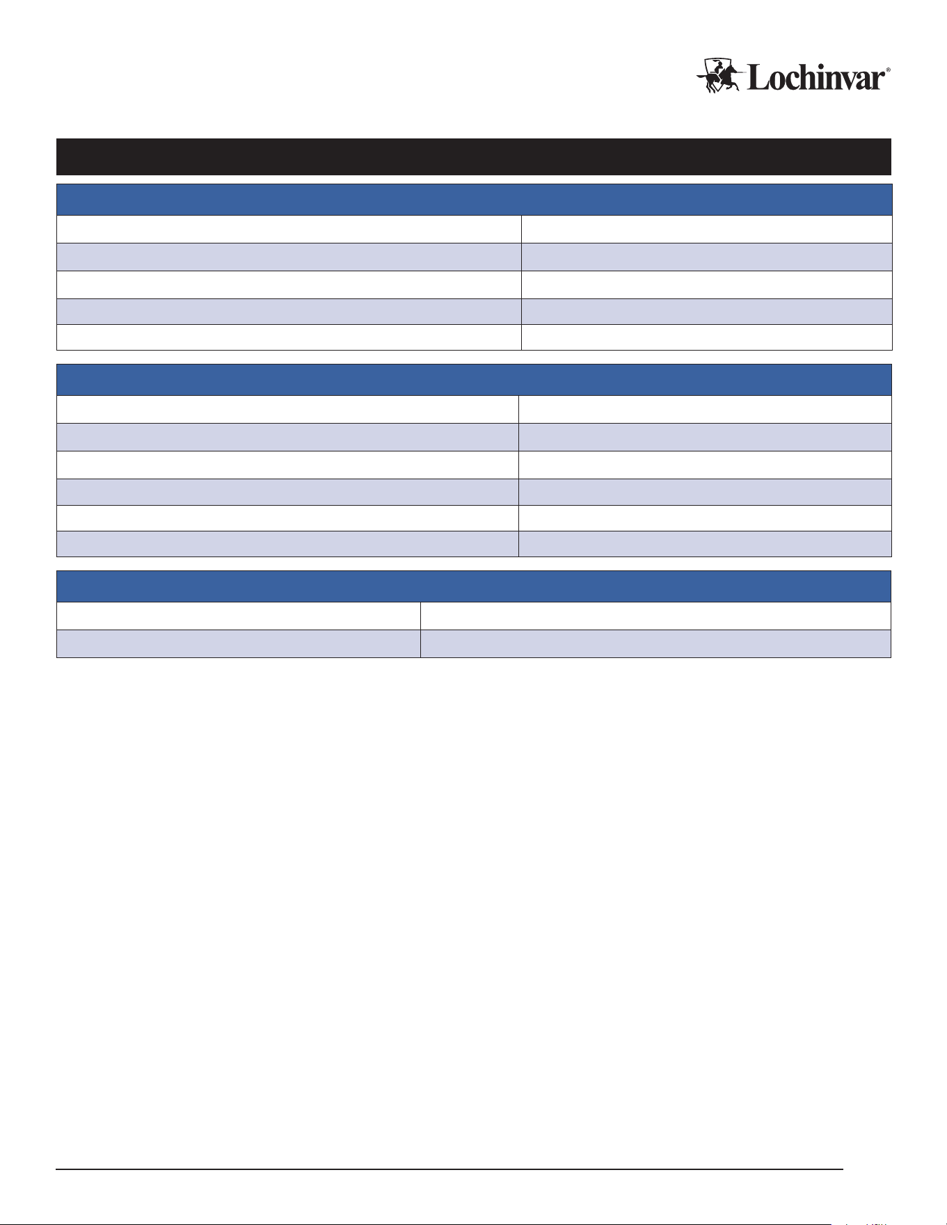
Electrical and Operational Specications
Electrical Specications
Voltage 120/1/60
Rated Current (RLA) 1 Amp
Minimum Circuit Ampacity (MCA) 1 Amp
Maximum Overcurrent Protection (MOCP) 15 Amps
Short Circuit Current Rating (SCCR) 5 kA
Operational Specications
Max Connected Heat Pumps 6
Maximum Connected Sensors 4x 10k NTC
Booster Pump Relay Outputs 2x 120v
Pump Relay Max Current 15 Amps VAC
Booster Pump Analog Output 1x 4-20mA or 0-10v
Booster Pump Stages 6 (Multi-pass only)
BMS Specications (MCP-G Only)
BMS Connection Types BACnet IP, BACnet MSTP
Baud 9600, 19200, 38400, 57600, 768000, 115200
Lochinvar, LLC 300 Maddox Simpson Parkway, Lebanon, Tennessee, 37090 ▪ (877).737.2840 ▪ Lochinvar.com
IM-MCP-NWS-L260303
5
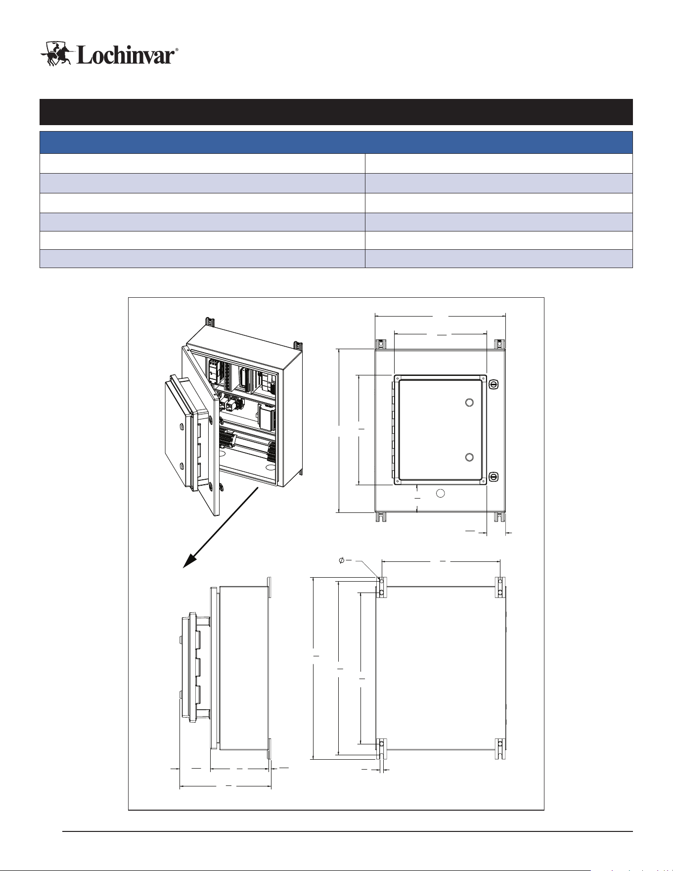
Physical Specications and Clearances
Physical Specications and Ratings
Ambient Operating Temperature 14-120 Deg. F
Ambient Operating Humidity 10-90 RH
Dimensions (in.) 16" W x 20" H x 11½" D
Weight 40 lb.
NEMA Class 4
Certications UL508A
Dimensions and Clearances
16"
3
3
8
"
13
3
8
"
2
5
16
"
11
5
16
"
20"
11
1
8
"
7
1
8
"
3
11
16
"
5
16
"
3
8
"
3
8
"
21
1
4
"
14
1
2
"
22
1
4
"
18
1
2
"
Note: Allow a 3 ft. service clearance
from the front of the MCP
Lochinvar, LLC 300 Maddox Simpson Parkway, Lebanon, Tennessee, 37090 ▪ (877).737.2840 ▪ Lochinvar.com
IM-MCP-NWS-L260303
6

Before Ordering Your MCP
Please ensure you are ordering the correct MCP for your project!
If integration into a Building Management System (BMS) is required, please order the MCP-G variant. This
avoids the need to add a BMS gateway to each individual heat pump.
If you need to control more than six individual heat pumps, consider the “Large Array” Main Control Panel (MCP-
LA). Review that product’s documentation for applicability to your project.
Control Panel Installation
Required Tools and Materials
In addition to all standard tools and material required for any electrical installation and to mount the control pan-
el, some of the other specialty tools required to support this installation include:
1. Heat transfer compound such as Honeywell part number 107408 or equivalent.
2. Electrical switch lockout devices - used to secure disconnect switches/breaker panels while servicing.
3. Electronic thermometer with range of 10°F - 210°F (-12°C - 100°C) including:
• Sensors capable of measuring surface temperatures on water piping
4. Volt-Ohm Multimeter - capable of measuring:
• AC Voltage up to 600 VAC
• DC Voltage up to 24 VDC
• Ohms up to 2,000,000 ohms
• Continuity
• Amperage up to 200 amps
Rough-In Checklist
Infrastructure must sometimes be installed prior to the installation of the unit. Items to consider for “rough-
In” installation include:
F Ethernet cables between the control panel and all connected heat pump locations.
F Primary 120v power wiring.
F Control wires for attached devices and sensors.
F Site prep for mounting the MCP.
Please refer to the appropriate sections of the manual for the specific details associated with each item.
Transportation, Placement, Mounting
IMPORTANT!
Do not remove, cover, or deface any permanent instructions, wiring diagrams, labels, or the rating labels
present on the unit. These are important for installation and service.
Lochinvar, LLC 300 Maddox Simpson Parkway, Lebanon, Tennessee, 37090 ▪ (877).737.2840 ▪ Lochinvar.com
IM-MCP-NWS-L260303
7

When Transporting the Control Panel:
1. Transport the unit with care appropriate to prevent damage to electronic devices.
2. Do not expose the panel to condensing conditions, extreme heat or extreme cold.
Placement considerations for the control panel:
F Ensure the location meets all requirements for ambient temperature, structural support, unit dimensions,
operational and service clearances. See physical specications to conrm.
F Mounting location must be structurally stable.
F Mounting location should be easily accessible for visual inspection and for regular service.
F Mounting location should ideally allow for protection from the elements during service work, which may
require laptops or opening the control panel door.
F Mounting location should avoid generating temperature extremes in the panel, such as rooftop mounting
in very hot environments in direct sunlight.
Mounting the Control Panel
The control panel has four anchor points to mount to a wall or vertical support structure. Use appropriate anchors or
bolts to attach the panel to the mounting surface. See the dimensional drawings for the MCP to prepare properly for
mounting bolt spacing and placement.
Control panels can be surface mounted directly on suitably sound wall surfaces. However, using a secondary
mounting system such as unistrut can allow for improved airow behind the unit. This can reduce risks of con-
densation corrosion or heat buildup in the control panel. When possible, Lochinvar recommends using spacers
or mounting systems behind the control panel.
Always mount the control panel in the correct orientation. Do not mount the panel inverted or rotated from its
normal orientation.
Power Wiring
WARNING
Improper handling of unit electrical power can result in immediate equipment damage, res, injury, and
death. Ensure only qualied personnel interact with main power lines. Never work while power is live;
use all possible safety precautions and perform all work in accordance with appropriate local codes,
National Electric Code, and/or CSA regulations.
Main Control Panels are voltage-specic, and require proper planning to provide the electrical support appropriate to
each unit. Please be sure to refer to the product’s electrical specications, project documentation, and the requirements
and installation instructions below.
Power Requirements:
1. Voltage is above 100v.
2. Power is clean, reliable, and well grounded.
3. Wire and breakers are appropriately sized for the load.
4. Wire and breakers are properly specied for the environment they are installed in.
5. Backup generators should include line conditioning suitable for running electronics.
6. Follow manufacturer’s torque specications for all power wire equipment by others.
Lochinvar, LLC 300 Maddox Simpson Parkway, Lebanon, Tennessee, 37090 ▪ (877).737.2840 ▪ Lochinvar.com
IM-MCP-NWS-L260303
8
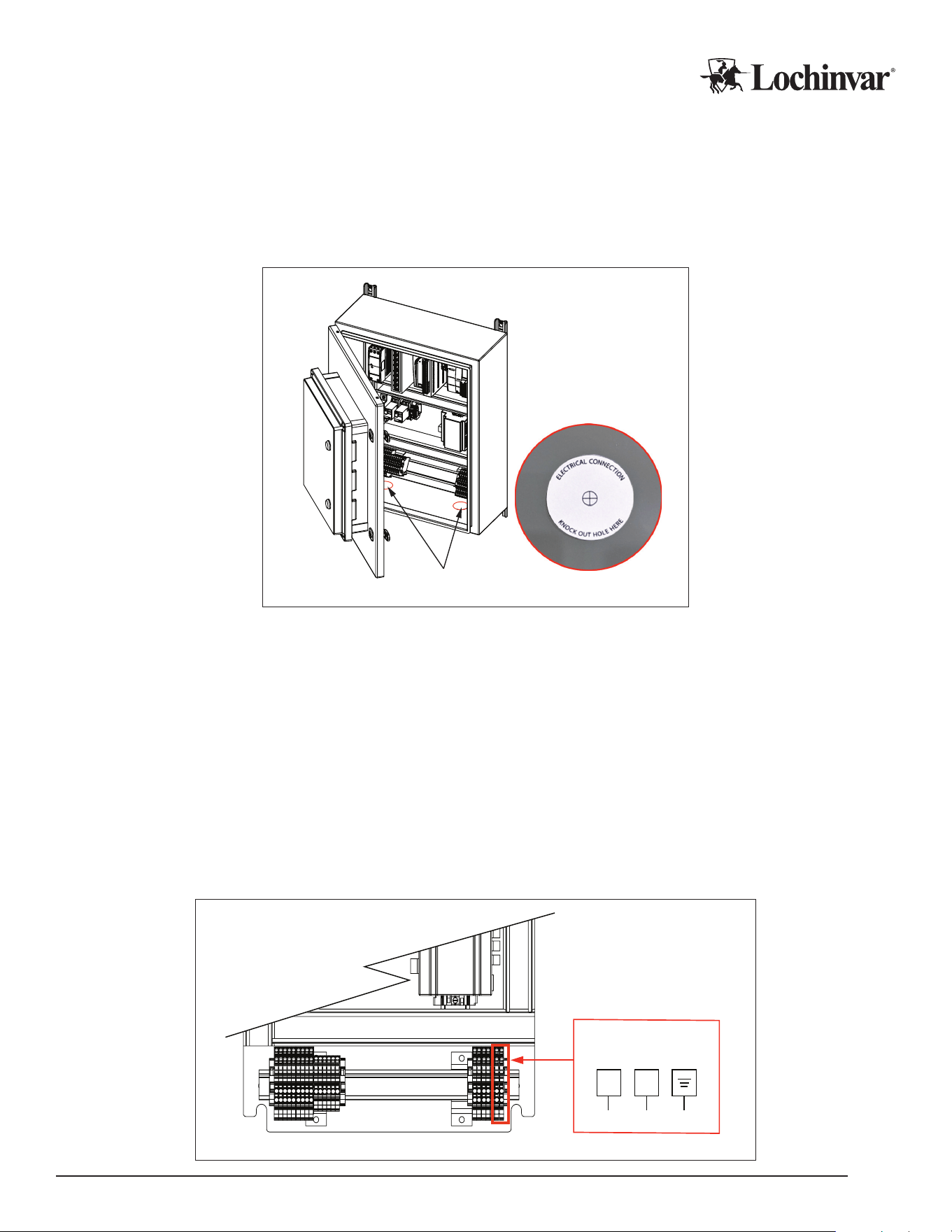
Power Wiring Installation
Electricians must create their own entry points into the MCP. There are two points that require creation of an
access hole, both marked with “Knock Out Hole Here” stickers. All holes should be weather tight when installa-
tion is completed.
Figure 1: Open Electrical Control Panel and Locate the Knockout Holes
Electrical Knockouts
1. Ensure the control panel is powered down when making electrical connections.
2. Open the panel enclosure.
3. Create a power wire access point on the MCP: typically, following the knockout sticker guidance on the
inside bottom face of the enclosure is recommended.
4. Run conduit to/through the knockouts with appropriate, weather-tight connections, and pull wire into the
enclosure.
5. Make the nal power wire and ground wire connections in accordance with the power wiring diagram. Use
0.5Nm of torque on wire terminals in the heat pump.
6. Tug test the new connections, and then close the electrical enclosure. It is now safe to restore power to the
control panel.
Figure 2: Power Wire Connections
Power Wiring
Power Wiring
N1
Lochinvar, LLC 300 Maddox Simpson Parkway, Lebanon, Tennessee, 37090 ▪ (877).737.2840 ▪ Lochinvar.com
IM-MCP-NWS-L260303
9

Control Wiring
Main Control Panels have several contact points for eld wiring of external controls.
Lochinvar recommends running enough conductors to use all available contacts if the installation site
would make wire retrots challenging, even if those contacts are not intended for use during the initial installa-
tion. This allows changes and reconguration to happen seamlessly in the future. Additional conductors to allow
for wire breakage, and/or the addition of future accessories, is also recommended.
The following drawing and notes provide a quick reference of the available contacts in the control panel, and what
they are used for. For more advanced conguration guidance, see the Conguration section of this manual and/or
instructions for any relevant accessories.
All control wiring should follow best practices, local codes and regulations, and NEC/CSA guidelines.
Do not steal power from powered contacts for external devices. Follow all ratings and wire types for the contacts
detailed below.
Control Wiring Installation
1. Ensure the control panel is powered down when making electrical connections.
2. Open the panel enclosure.
3. Create a control wire access point on the MCP: typically, following the knockout sticker guidance on the inside bottom
face of the enclosure is recommended.
4. Run all external sensor wires and/or control wiring for eld accessories through the access point, using a
weather tight connection method.
5. Once in the enclosure, wires can be attached to their target terminals. See Figure 3 below for specic wiring
connections.
6. Tug test the new connections, and then close the electrical enclosure. It is now safe to restore power to the
control panel.
CAUTION
Contacts labeled “Dry” are intended to switch power from external sources. DO NOT APPLY EXTERNAL
POWER to any contact that is not “Dry”. Equipment damage and system failure can result from applying
power to a powered contact. Follow all power specs for each contact.
Lochinvar, LLC 300 Maddox Simpson Parkway, Lebanon, Tennessee, 37090 ▪ (877).737.2840 ▪ Lochinvar.com
IM-MCP-NWS-L260303
10
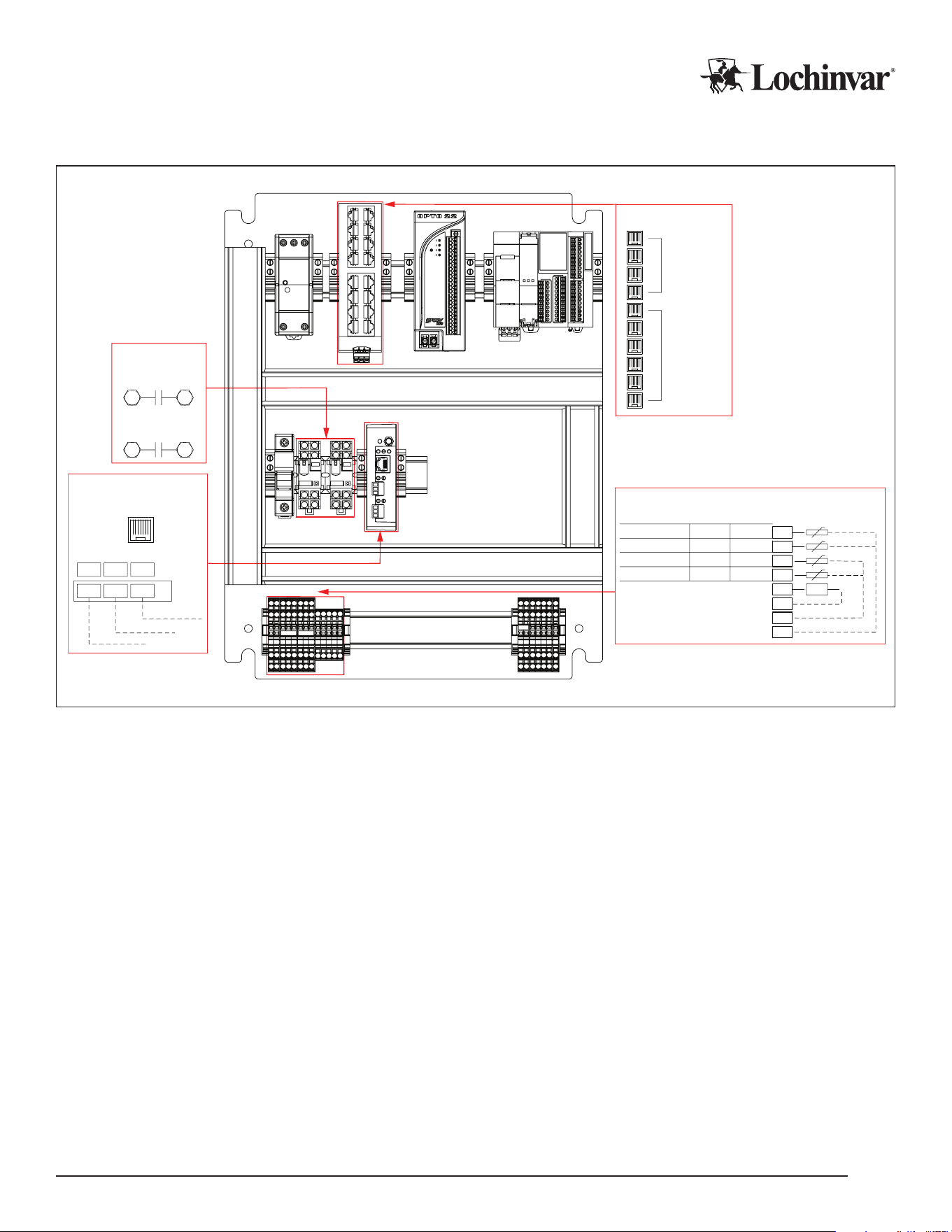
Figure 3: Control Wring Connections
4 Ports
reserved
for Internal
Use and
Service
Up to 6
Heat Pumps
may be
connected
Ethernet Switch
0V
0V
0V
P13
T4
T3
T1
T2
Customer Terminal Block
+VFD-
Temperature Probes
Tank Sensor (High/Cold)
Tank Sensor (Med/Cold)
Tank Sensor (Low/Cold)
Termination/Outlet Sensor
Analog Pump Output
Multi-Pass
Single-Pass
Cold Trigger
Low
Cold Trigger
Cold Trigger
Mid
High
Warm Trigger Termination
Field Wiring
BACnet +
BACnet -
BACnet GND
MSA
R2
GND
RX-
TX+
Intesis
B3B2B1
RS485 Port
BMS
(MCP-G only)
Ethernet Port
Ethernet Switch
Pump Contacts
BMS
CTB
8
12
S.P.R.
Source Loop
59
Heating Loop
H.P.R.
Pump Contacts
Field Wiring Control Points
Analog Pump Output: These terminals output a 0-10v or 4-20ma signal to control modulating equipment, such
as an external circulator, in response to current staging demands.
BMS (MCP-G Only): The Ethernet or Serial connection used to connect to building automation systems.
Ethernet: Ethernet is used for connecting to all attached heat pumps. Each heat pump to be controlled needs to
be connected to the ethernet switch. No more than six heat pumps can be connected in this way.
Pump Contacts (HPR and SPR): These dry sets of contacts close when the system is operating for a heat
demand. They are intended to trigger control devices such as valves or pumps on the heating side (HPR) of the
system, or the source loop side (SPR) for water source heat pumps.
Tank Sensor terminals (T1-T3): These sensor inputs allow the MCP to monitor and control the tank tempera-
tures. Take care that the tank sensors are installed in accordance with the sensor diagrams appropriate to the
type of heat pump in use, single- or multi-pass. Tank sensor behavior changes in dierent modes of operation.
See Tank Sensor detail sections following this section.
Outlet/Termination Sensor (T4): Sensor input for single-pass demand termination, or multi-pass “Minimum
Outlet” trigger in multi-tank applications. In single-tank multi-pass applications, this sensor is a “Warm Trigger”
sensor. See Tank Sensor detail sections following this section.
Lochinvar, LLC 300 Maddox Simpson Parkway, Lebanon, Tennessee, 37090 ▪ (877).737.2840 ▪ Lochinvar.com
IM-MCP-NWS-L260303
11
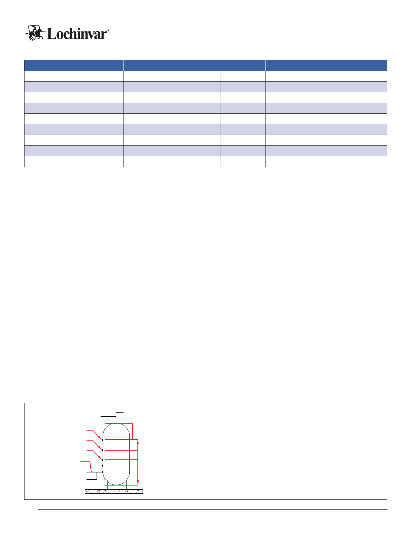
Table 1: MCP Control Wiring Specications
Contact Location Terminals Wire Type Power
Analog Pump Output
Analog P13 0v Stranded/Shielded 4-20ma
BMS
1
RX- TX+ G Stranded/Shielded Variable
Ethernet
2
(Note 2) - – CAT-5 or CAT-6 –
Pump Contact HPR Relay 9 5 Any
Dry
3
Pump Contact SPR Relay 12 8 Any
Dry
3
Tank Sensor (High/Cold)
4
Analog T1 0v Stranded/Shielded 24Vdc
Tank Sensor (Med/Cold)
4
Analog T2 0v Stranded/Shielded 24Vdc
Tank Sensor (Low/Cold)
4
Analog T3 0v Stranded/Shielded 24Vdc
Termination/Outlet Sensor
4
Analog T4 0v Stranded/Shielded 24Vdc
Notes:
¹
For MCP-G Only.
2
Ethernet Port on BMS for BACnet IP, and on switch for heat pump connections.
3
All Relay contacts are rated for 15A/250VAC, or 6A/28VDC max.
4
Sensor outputs vary by mode of operation. See tank sensor sections for details.
Single-Pass Tank Sensors for MCPs
Main Control Panels on single-pass DHW systems use a total of 2 or 3 tank sensors to determine how many
heat pumps, or “stages”, to call to satisfy a heat demand. In addition, one pipe mounted sensor is used to ter-
minate the demand.
Sensor placement must consider the “cold cycle volume” of all heat pumps that may run when a given sensor is
triggered. This means that sensors must be placed so that at least that much water volume exists between the
tank sensor in question, and the termination sensor. If a sensor will call 2 heat pumps, you will need double the
“cold cycle volume” of the heat pump model in use.
For more specic information about single-pass systems, cycle volumes, and tank sensor installation, please refer
to the installation manuals for your specic heat pumps, and the tank sensor installation manual.
The number of single-pass heat pumps that run for each sensor is dependent on the total number of heat
pumps connected to the MCP. Stages will trigger as follows for each tank sensor:
Low Sensor: This will trigger a single stage (heat pump).
Mid Sensor: This will trigger 50% of available heat pumps, rounded up.
High Sensor: This will trigger the Max Stage Count (congurable) number of heat pumps.
Termination Sensor: After the tank sensors satisfy, the demand will continue until the termination sensor senses
water at or above the cut in/cut out temperature.
Figure 4: Single-pass, Multiple Heat Pumps with Central Controller
To Heat Pump
From Heat Pump
Low Sensor
DHW Out
Cold Cycle Volumes
Cold In
Mid Sensor
High Sensor
Termination Sensor
Capacity Volume
Notes:
1. Minimum CCV is listed in the heat pump specifications.
2. Multiply minimum CCV by the minimum number of heat pumps to operate
simultaneously for each sensor position.
3. Ensure high sensor point allows for adequate capacity volume above the sensor.
Lochinvar, LLC 300 Maddox Simpson Parkway, Lebanon, Tennessee, 37090 ▪ (877).737.2840 ▪ Lochinvar.com
IM-MCP-NWS-L260303
12
Multi-Pass Tank Sensors for MCPs
Main Control Panels on multi-pass systems are set up one of two ways, depending on whether the heat pumps
are serving a single tank, or multiple tanks in parallel.
On a single tank, two sensors are used: a cold trigger sensor, and a warm trigger sensor. The cold trigger sensor
is positioned so there is at least the “cold cycle volume” of water between the sensor and the heat pump outlet
pipe on the tank, and the warm trigger sensor is positioned so there is at least the “warm cycle volume” of water
between the sensor and the heat pump outlet pipe.
On multiple-tank arrays, multiple cold trigger sensors can be used, up to a maximum of three, one in each tank.
One outlet sensor is then mounted on the pipe serving hot water to the mixing valve, which will trigger a maxi-
mum stage demand if necessary.
For more specic information about multi-pass systems, cycle volumes, and tank sensor installation, please refer
to the installation manuals for your specic heat pumps, and the tank sensor installation manual.
Staging in multi-pass systems is activated on time and temperature, and sensors participate in this process dierently:
Cold Trigger Sensor(s): If a cold trigger sensor activates, one heat pump will run, with more heat pumps triggering
over time if the sensed temperature doesn’t rise. When any cold trigger sensor is satised, all demands end.
Warm Trigger Sensor: If a warm trigger sensor activates, one heat pump will run. More heat pumps will trigger over
time if the cold trigger sensor temperature doesn’t rise. Demands will continue until any cold trigger sensor satises.
Min Outlet Temperature Sensor: When a minimum outlet temperature sensor triggers, the Maximum Stage Count
(congurable) number of heat pumps will run immediately.
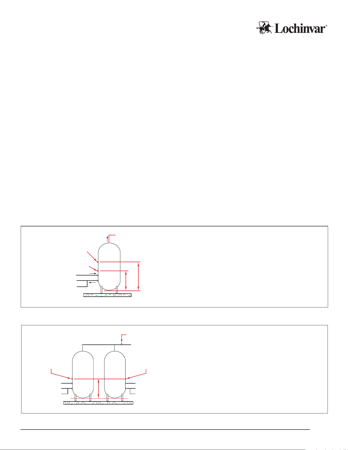
Figure 5: Multi-pass, Single Tank Sensor Locations
To Heat Pump
From Heat Pump
Cold Trigger Sensor
DHW/Recirc Out
Warm Trigger Sensor
Warm Cycle Volume
Cold Cycle
Volume
Cold/Recirc In
Notes:
1. CT sensors mounted at a maximum of 1/5 of total tank height.
2. WT sensors mounted at a maximum of 2/5 of total tank height.
3. Min CCV, WCV, and tank size are in heat pump specifications.
Figure 6: Multi-pass, Multiple Tanks with Central Controller
Cold Trigger Sensor 1
1/2
Cold Cycle
Volume
Warm Trigger Sensor
DHW/Recirc Out
Cold Trigger Sensor 2
Tank 1 Tank 2
To Heat Pump
Cold/Recirc In
From Heat Pump
To Heat Pump
Cold/Recirc In
From Heat Pump
1/2
Cold Cycle
Volume
Notes:
1. CT sensors mounted at a maximum of 1/5 of total tank height.
2. Minimum CCV are in the heat pump specifications: ensure
enough CCV is included for the minimum number of heat pumps
to run simultaneously.
Lochinvar, LLC 300 Maddox Simpson Parkway, Lebanon, Tennessee, 37090 ▪ (877).737.2840 ▪ Lochinvar.com
IM-MCP-NWS-L260303
13

Conguration
Conguring the MCP will require active main power for the control panel, as well as on all attached heat pumps.
CAUTION
Note that while activating the main power for programming is safe, turning compressor operation “on” at
this stage is not. Complete your heat pumps’ Pre-Startup Checklist before pressing the “on” button
in the control interface on any attached heat pumps! Operating the heat pump compressor before all
checks have been performed can result in severe equipment damage or major component failure.
IMPORTANT!
MCP conguration is specic to the software version installed on the control panel. A Programming and Opera-
tion Manual (POM) is included with your MCP for the software version installed in the factory; however, software
can be updated on installed hardware, and software is updated and improved regularly, so the installed soft-
ware on the MCP may not always match the version shipped with the controller. ALWAYS check the currently
installed software version before conguration, and ensure you are using the POM for the correct software.
BMS Installation and Conguration (MCP-G Only)
WARNING
DO NOT connect the heat pump to the building network prior to gateway conguration! This will potentially over-
write the default IP address of the gateway and make nding the gateway on the network more dicult. If this
occurs, it may be necessary to nd the gateway on the network using the MAC address on the gateway label.
Conguration Prep and Login
1. Power up the controller, and allow it to nish its startup, before attempting to congure the BMS gateway.
After startup is completed, connect a laptop directly to the gateway, using the ethernet port on the gateway.
This component is shown in the “eld wiring control points” diagram in the “control wiring” section of this
manual, for reference.
2. Open a web browser and connect directly to https://192.168.1.24
a. You may get a “Web Server Security Uncongured” message. It is ok to proceed with HTTPS from that
warning message.
b. You may get a “Your Connection is not Private” message. If so, click “Advanced”, and click “proceed to
192.168.1.24 (unsafe)”.
3. Login to the gateway web interface. Username is “admin”. Password is written on the gateway’s label, and
is also available via QR code on the gateway. It may be necessary to temporarily unseat the gateway from
the DIN rail to read the label.
4. On the rst login, the security mode will need to be set. “Basic HTTP” or “HTTPS with own trusted certi-
cate” is recommended.
After selecting a mode, you will get a “redirecting” message, and then the Field server GUI should open.
Lochinvar, LLC 300 Maddox Simpson Parkway, Lebanon, Tennessee, 37090 ▪ (877).737.2840 ▪ Lochinvar.com
IM-MCP-NWS-L260303
14

Network Settings
1. To congure network settings, on the GUI landing page, click on the “Settings” tab. Within “Settings”, click
on the “Network” tab.
a. On the rst connection, you will get a warning message that you are about to leave the registration process.
Click “Exit Registration”.
2. You should now see a page with “ETH 1” and “Routing” tabs. Click the “Routing” tab.
a. Select the default connection in the rst row of the table.
b. Click the “Add Rule Button” to add a new row.
c. Set a new Destination Network, Netmask, and Gateway IP Address as needed.
d. Set the priority for each connection from 1 (highest) to 255 (lowest).
e. Click the “Save” button.
3. Now click the “ETH 1” tab to access the ethernet settings.
Be advised, if IP addresses are changed, you will need to reconnect to the gateway via your browser using the
new IP address before you can continue with conguration settings! Only proceed once ready to connect to the
building’s network.
4. DHCP to automatically accept IP settings can be enabled here, or IP settings can be manually congured.
a. For manual conguration, set IP Address, Netmask, Default Gateway, and Domain Name Server.
b. If the gateway will be connected to a router, the gateway MUST set the “Gateway” eld to the IP address
of the router.
5. Click “Save” to activate the settings changes.
Protonode Conguration
To congure the protonode, start from the “Device List” page in the GUI and click “Settings”.
1. Choose “Conguration”, and click the “Proles Conguration” Button. Set the “protocol_select” eld
a. Set to 1 for BACnet IP.
b. Set to 2 for BACnet MSTP.
c. Set to 3 for BACnet MSTP (Single Node).
d. Hit “submit” after entering the correct value.
Selecting a protocol will change the list of visible parameters to only parameters applicable to your protocol.
2. Set the remaining parameters according to the needs of your network and BMS system. Press “submit” to
save each value.
Lochinvar, LLC 300 Maddox Simpson Parkway, Lebanon, Tennessee, 37090 ▪ (877).737.2840 ▪ Lochinvar.com
IM-MCP-NWS-L260303
15
Table 2: Conguration Parameters for BMS Gateway
Parameter Protocol Values Description
protocol_select All 1,2,3
Protocol Selector: set to 1: BACnet IP. 2: BACnet MSTP. 3:
BACnet MSTP (single node).
mod_baud_rate
All 9600-19200-38400-57600
Set to the Modbus RTU baud rate required.
mod_parity
All None,Even,Odd
Set to the Modbus parity required (Factory Set)
mod_data_bits
All 7,8
Set to the Modbus data bits required (Factory Set)
mod_stop_bits
All 1,2
Set to the Mobus stop bits required (Factory Set)
network_nr
1, 3 1 - 65535
Sets the BACnet network number for the gateway.
node_oset
1, 3 0 - 4194303
Sets the BACNnet device instance (Device address plus oset).
bac_ip_port
1 1 - 65535
Set to the BACnet IP port required for the gateway.
bac_cov_option
ALL enable, disable
Enables or Disables COVs for the BACnet application
bac_bbmd_option
1 BBMD, -
Enables or Disables BBMD for the BACnet application
bac_virt_nodes 1, 3 No, Yes
No: single heat pump on gateway. Yes: multiple heat pumps on
gateway.
bac_device_id
2 1 - 4194303
Sets this BACnet device instance
bac_mac_addr
2, 3 1 - 127
Sets the BACnet MSTP MAC address
bac_baud_rate
2, 3 9600-19200-38400-76800
Sets the BACnet MSTP Baud Rate
bac_max_master
2, 3 1 - 127
Sets the BACnet MSTP max master
bac_max_info_fr
2, 3 1 - 65535
Sets max number of frames before token must be passed
3. Connect the gateway to the building network.
4. Reconnect to the new gateway IP address with your web browser, if necessary. Verify communications in
accordance with the “Testing” instructions in the next section.
5. The gateway should now allow for building management system integration. Points lists for your equipment
is available in a following subsection of this manual.
Points List
Following is the list of available points on the MCP-G for integration with BACnet BMS systems. Points for up
to six attached heat pumps are available, in addition to the central control parameters.
Table 3: Relevant Data Points for MCP-G: Writable Values
Prole Description Prole Name Description of Operation
Cycle State
Cycle Set to 1 to enable operation, 0 to disable operation.
Leaving Water Setpoint (SP) / (DR) Lw_Set Target leaving water temperature for single-pass operation (Deg F)
Cut-In/Out Setpoint (SP)
Cut_in_out_set Activation/Termination temperature for single-pass operation (Deg F)
Temperature Setpoint Tank Tank_Set Target tank temperature (Deg F)
Cold Setpoint / Shed (DR) Cold_Set Activation temperature for cold sensor in multi-pass operation (Deg F)
Hot Setpoint (MP) / Loadup (DR) Hot_Set Activation temperature for warm sensor in multi-pass operation (Deg F)
Lochinvar, LLC 300 Maddox Simpson Parkway, Lebanon, Tennessee, 37090 ▪ (877).737.2840 ▪ Lochinvar.com
IM-MCP-NWS-L260303
16

Table 4: Relevant Data Points for MCP-G: Read-Only Values
Prole Description Prole Name Description of Operation
Control Mode (Local/BMS)
Display_Lock 0= Local Control. 1= BMS Control
Pump Speed Pump_Status 0-100% readout for variable speed pump outputs.
System Cycle Status
Cycle_Status Whether MCP-G is currently on or o
System Status (Idle / Active / Others) System_Status Whether heat demand is active or idle
System Alarms (MCP Generated) System_Alarm Communication Fault, Probe Fault, Ambient (out of operating range) faults.
Number of Installed Units Installed_Units The number of heat pumps the MCP is congured to operate.
Number of Units Currently Running Running_Units The number of heat pumps currently in active demand status.
Tank Probe 1 TankProbe1 Cold Trigger 1 (Multi-pass) / Low Sensor (Single-pass)
Tank Probe 2 TankProbe2 Cold Trigger 2 (Multi-pass) / Mid Sensor (Single-pass)
Tank Probe 3 TankProbe3 Cold Trigger 3 (Multi-pass) / High Sensor (Single-pass)
Tank Probe 4 TankProbe4
Termination sensor for single-pass operation. Warm trigger or Min Outlet sensor
for multi-pass. (Deg F.)
Alarm Number Unit 1 UnitAlarm1 Alarm Status of Heat Pump 1
Alarm Number Unit 2 UnitAlarm2 Alarm Status of Heat Pump 2
Alarm Number Unit 3 UnitAlarm3 Alarm Status of Heat Pump 3
Alarm Number Unit 4 UnitAlarm4 Alarm Status of Heat Pump 4
Alarm Number Unit 5 UnitAlarm5 Alarm Status of Heat Pump 5
Alarm Number Unit 6 UnitAlarm6 Alarm Status of Heat Pump 6
Compressor Run Hours1 CompressorRunHRS1 Cumulative Run Hours for Heat Pump 1
Compressor Run Hours2 CompressorRunHRS2 Cumulative Run Hours for Heat Pump 2
Compressor Run Hours3 CompressorRunHRS3 Cumulative Run Hours for Heat Pump 3
Compressor Run Hours4 CompressorRunHRS4 Cumulative Run Hours for Heat Pump 4
Compressor Run Hours5 CompressorRunHRS5 Cumulative Run Hours for Heat Pump 5
Compressor Run Hours6 CompressorRunHRS6 Cumulative Run Hours for Heat Pump 6
Lochinvar, LLC 300 Maddox Simpson Parkway, Lebanon, Tennessee, 37090 ▪ (877).737.2840 ▪ Lochinvar.com
IM-MCP-NWS-L260303
17

BMS Testing
Good practice will include thorough verication that values reported by the heat pump match the values re-
ceived in the BMS system. Ideally, this would include monitoring through an active heat demand and comparing
BMS reported values to heat pump reported values.
In addition, system communication can be checked. For serial connections, check that the TX and RX LEDs are
rapidly ashing.
You can also log into the eld server GUI with a web browser, as in the “conguration” section. From there,
clicking on “Diagnostics and Debugging”, and then on “connections”, shows you a table of communication con-
nections. The “errors” column would indicate if there are errors requiring additional troubleshooting.
Communication errors are usually caused by:
• Baud rate, parity, data bits or stop bits set incorrectly
• Device addresses incorrect
• Wiring problems
• Device not listed in the Web Congurator
• IP Addressing incorrect.
If communication errors cannot be troubleshot, a “Diagnostic Capture” can be taken and emailed to the factory
for assistance.
1. Connect to the eld server GUI with your web browser
2. Click on “Diagnostics”
3. Select “Full Diagnostic”
4. Set the capture time period
5. Click start. When the capture period is nished, a download button will appear.
6. Download the capture
7. Email the capture to the factory, along with any supporting information needed to describe your problem.
Lochinvar, LLC 300 Maddox Simpson Parkway, Lebanon, Tennessee, 37090 ▪ (877).737.2840 ▪ Lochinvar.com
IM-MCP-NWS-L260303
18

Pre-Startup Checklist
The following checklist is provided for reference, to assist in preparing for the eventual startup of the equipment.
Please contact your manufacturer’s representative MORE THAN ONE MONTH from your intended startup date.
The following checklist items will be reviewed for compliance before a nal startup is scheduled with a factory au-
thorized commissioning agent.
This list is Pre-Startup items specic to the MCP. Heat pumps have their own pre-startup checklists. Refer to the
heat pump documentation during any pre-startup review.
CAUTION
Heat pump startups may only occur with a factory authorized commissioning agent. Do not start
the heat pump before the authorized agent is on site and ready to assist, or you may void your
warranty and cause equipment damage or failure.
Placement and Physical Checks
F MCP is level, stable, and securely mounted.
F MCP has appropriate service clearance, and the access panel is not obstructed by pipes, wires, or other
obstacles.
Electrical Checks
F Main power wires are securely attached to the MCP and active.
F All control and communication wires are securely attached, and connected equipment is in place and
ready to operate.
Final Checks
F All conguration settings are checked and correct.
F All panels and enclosures are securely closed and axed.
Lochinvar, LLC 300 Maddox Simpson Parkway, Lebanon, Tennessee, 37090 ▪ (877).737.2840 ▪ Lochinvar.com
IM-MCP-NWS-L260303
19
Troubleshooting
Please use the following lists of startup issues, alerts and faults to assist with the diagnosis and troubleshoot-
ing of some common problems. More detailed information on alarms and other diagnostic and troubleshooting
terms is available in the Programming and Operation Manual for the software version on your MCP.
In the rare event that major components end up damaged or defective, you MUST obtain assistance and
approval from your rep or from Lochinvar to authorize warranty replacement, BEFORE the components
are removed from service.
Problem Check
Display Screen is Dark
Main power is active at breaker and input terminals.
Power Supply is providing 24v power.
Control screen is receiving power.
Conguration options don’t match manual MCP software version matches “Conguration” section in manual.
Any Heat Pumps are not visible on MCP
Display
Heat pumps are set to "External" mode.
Ethernet between HPs and MCP is good.
Ethernet switch is on and connected to Rio.
MCP is congured to correct number of HP's.
Heat Pumps are visible on MCP but show
“Disconnected”
Heat pumps are not in initial power up phase.
Ethernet between HPs and MCP is good.
Ethernet switch is on and connected to Rio.
Heat pumps are "on".
One heat pump runs, but MCP won’t stage
on additional heat pumps
"Max Stages" is set to high enough value.
Tank Sensors are wired to correct terminals.
Tank Sensors are reading correct values.
Mix and Staging interval has been met (multi-pass only).
Staging temp has been met (multi-pass only).
All heat pumps show "Connected".
Heat Pumps are short cycling
LWT Set and Cut-In/Out are far enough apart (Single-pass).
Tank Set and Trigger temps are far enough apart (Multi-pass).
Heat Pump(s) will not reach target LWT
(Single-pass)
Heat pumps are congured for Single-pass.
MCP is congured for Single-pass.
Target LWT on MCP is set correctly.
Lochinvar, LLC 300 Maddox Simpson Parkway, Lebanon, Tennessee, 37090 ▪ (877).737.2840 ▪ Lochinvar.com
IM-MCP-NWS-L260303
20

Limited Warranty
Commercial Heat Pump Water Heater System Control Panel
1 Year Limited Warranty
Eective
For ONE (1) Year, Lochinvar® LLC warrants the commercial heat pump system control panel against failure
due to defects in materials or workmanship. All Parts are warranted for ONE (1) year from the date of manu-
facture. This limited warranty is in eect when the control panel is installed within the United States or Canada,
provided it remains at its original place of installation.
Warranty coverage begins on the date of installation OR 60 days after the date of manufacture if installation can-
not be veried. Note: The date of manufacture can be determined using the Serial Number, located on the silver
rating label. The system control panel must bear the original rating label which has not been altered, defaced, or
removed, except as required by Lochinvar.
What is Covered
In the event of a defect in materials or workmanship appearing during the limited warranty period, Lochinvar will
repair, or at our discretion, replace any defective part covered under this limited warranty. Any replacement part
will be warranted only for the unexpired portion of the original limited warranty period.
If an identical model is no longer available due to a change in law, regulation, or standard, Lochinvar will replace
the product with one having at least the same capacity and input. In these instances, you will have the option of
paying the dierence between what was paid for the original model and the new model with the additional features;
or receiving a refund of the portion of the purchase price allocable, on a pro-rata basis, to the unexpired portion of
the limited warranty period.
What is Not Covered (Problems Caused By)
• Improper connections, voltage, wiring, or fusing
• Improper installation, sizing, delivery, or maintenance
• Failure to follow printed instructions enclosed with the product
• Abuse, misuse, accident, re, ood, Acts of God
• Failure to conduct authorized factory start up as required
• Failure to properly perform maintenance, as outlined in the instruction manuals provided by the
manufacturer
• Alterations that change the intended or certied use of the product
• Failure to follow applicable local code authority having jurisdiction
• Service trips to explain proper installation, use, or maintenance of the product/control panel or to describe
compliance requirements under applicable codes and regulations
• Replacement parts after expiration of this warranty
• Premium associated with after hours or overtime labor
• Any accident to the system control, any misuse, abuse or alteration of it, any operation of it in a modied
form, will void this warranty
Lochinvar, LLC 300 Maddox Simpson Parkway, Lebanon, Tennessee, 37090 ▪ (877).737.2840 ▪ Lochinvar.com
IM-MCP-NWS-L260303
21

Owner’s Responsibilities
Owner’s Are Responsible For:
• All labor, shipping, delivery, installation, and handling costs associated with the repair and/or
replacement, including removal cost of the system control panel
• All cost necessary or incidental for any materials and/or permits required for installation of the replacement
part
• Selecting a qualied service provider. Visit www Lochinvar.com for a list of service providers in your area
• Following all instructions provided with the product
• Retaining all bills of sale or receipts for proof of installation
• Providing copies of all service and maintenance records
• Contacting your installer or dealer as soon as any problem or defect is noticed
Limitations
NOTWITHSTANDING ANYTHING ELSE TO THE CONTRARY, THIS IS YOUR SOLE AND EXCLUSIVE WARRANTY. ALL
OTHER WARRANTIES, INCLUDING A WARRANTY OF MERCHANTABILITY OR FITNESS FOR A PARTICULAR PUR-
POSE ARE EXPRESSLY DISCLAIMED. SELLER SHALL NOT BE LIABLE FOR ANY CONSEQUENTIAL, INCIDENTAL,
SPECIAL, PUNITIVE OR OTHER INDIRECT DAMAGES. TOTAL LIABILITY ARISING AT ANY TIME SHALL NOT EX-
CEED THE PURCHASE PRICE PAID WHETHER BASED ON CONTRACT, TORT, STRICT LIABILITY OR ANY OTHER
LEGAL THEORY.
Claim Procedure
Any claim under this warranty should be initiated with the dealer who sold the heater, or with any other dealer
handling the warrantor’s products. If this is not practicable, the owner should contact:
Lochinvar, LLC
300 Maddox Simpson Parkway
Lebanon, TN 37090
(615) 889-8900
Service Inquiries
For service inquiries, be prepared to provide the following information: name, address, and telephone number;
the model and serial number of the water heater; proof of installation; and a clear description of the problem.
For your records, ll in the product:
Serial Number: ______________________________
Model Number: ______________________________
Lochinvar, LLC 300 Maddox Simpson Parkway, Lebanon, Tennessee, 37090 ▪ (877).737.2840 ▪ Lochinvar.com
IM-MCP-NWS-L260303
22

Service Log
Issue Description Date Servicer
Lochinvar, LLC 300 Maddox Simpson Parkway, Lebanon, Tennessee, 37090 ▪ (877).737.2840 ▪ Lochinvar.com
IM-MCP-NWS-L260303
23

Lochinvar, LLC 300 Maddox Simpson Parkway, Lebanon, Tennessee, 37090 ▪ (877).737.2840 ▪ Lochinvar.com