INSTALLATION AND
OPERATION MANUAL
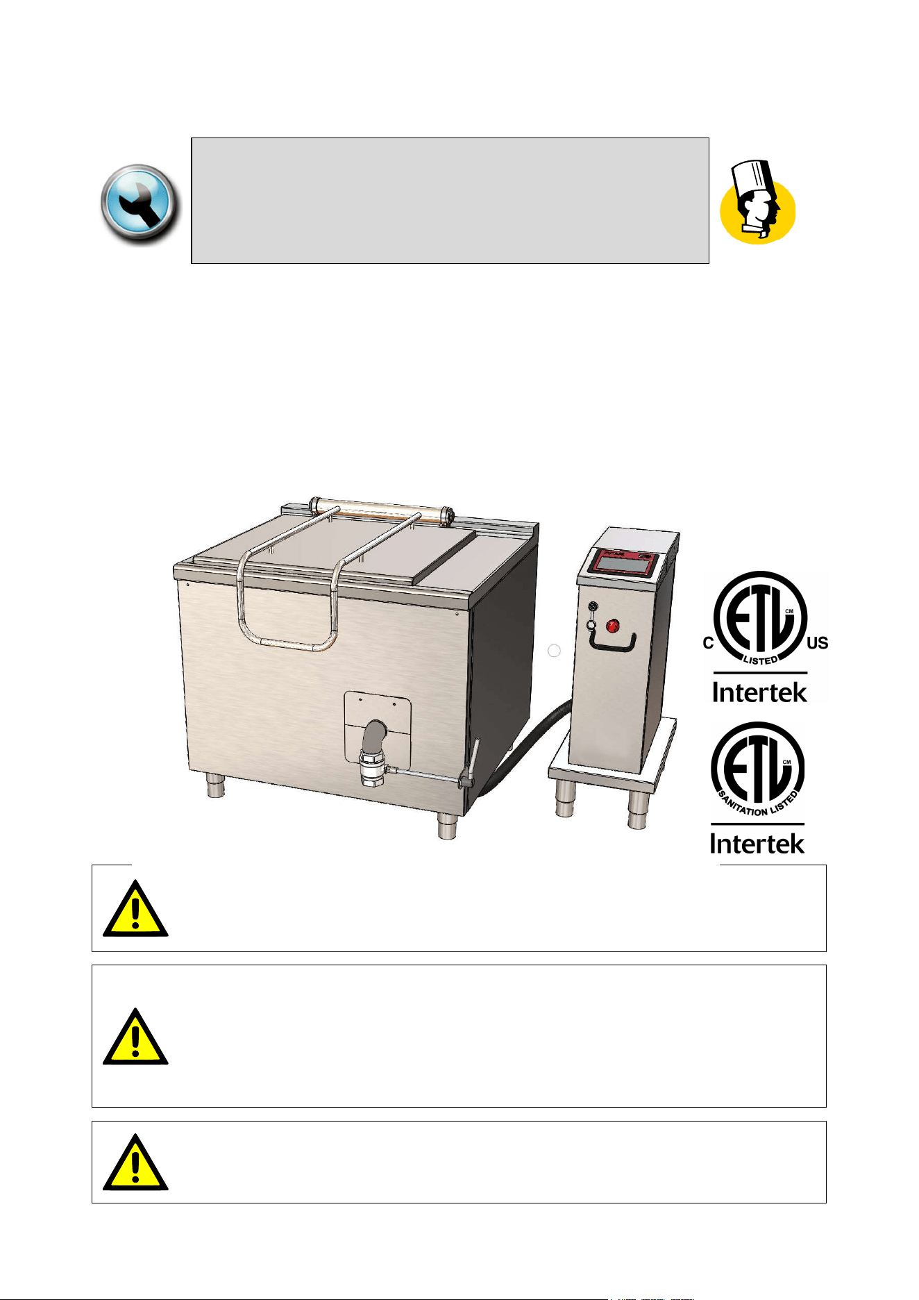
“MULTICOOKER”
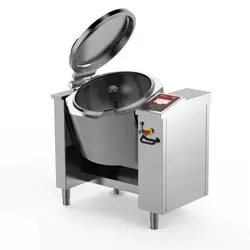
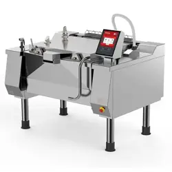
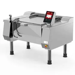
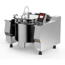
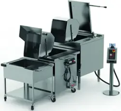
AUTOMATIC DIRECT COOKERS, GAS TYPE
MODD. UCPMDG1-… ; UCPMDG1-… L
MODD. UCPMDG2-… ; UCPMDG2-… L
FOR YOUR SAFETY:
Do not store or use gasoline or any other flammable liquids and
vapours in the vicinity of this or any other appliance.
WARNING:
Improper installation, operation, adjustment, alteration, service or
maintenance can cause property damage, injury or death.
Read the installation, operating and maintenance instructions
thoroughly before installing, operating or servicing this equipment.
PURCHASER: Instructions to be followed in the event that the operator
of this appliance smells gas must be posted in a prominent location.
This information shall be obtained by consulting the local gas supplier.
05
-
UCPMDG
-
DIMU
-
00
-
EN
INTRODUCTION
2
IN CASE OF TECHNICAL ASSISTANCE, INDICATE:
MODEL : ______________________________________________________
NR. SERIAL : ______________________________________________________
The model and serial number are indicated on the rating plate
Firex srl, Z.I.Gresal, 28
32036 Sedico
BELLUNO ITALIA
TELEPHONE: (0039) 852700 ; FAX: (0039) 852858
The manual is available upon request to:
specifying model and serial number
(The model and serial number data are indicated on the rating plate).
.

INTRODUCTION
05
-
UCPMDG
-
DIMU
-
00
-
EN
3
TABLE OF CONTENTS
1 INTRODUCTION.................................................................................................................................... 6
1.1 SYMBOLS AND PICTORIALS .................................................................................................................. 6
1.2 GENERAL REMINDERS ........................................................................................................................... 6
1.3 IMPORTANT NOTES FOR INSTALLATION ............................................................................................. 7
2 SAFETY ................................................................................................................................................. 8
2.1 OVERVIEW ............................................................................................................................................... 8
2.2 WARNINGS ............................................................................................................................................... 9
3 DESCRIPTION OF THE MACHINE ..................................................................................................... 11
3.1 DESCRIPTION ........................................................................................................................................ 11
3.2 MATERIALS ............................................................................................................................................ 11
3.3 OPTIONAL .............................................................................................................................................. 11
3.3.1 SHOWER FOR WASHING ................................................................................................................................. 11
3.4 OPERATING PARTS ............................................................................................................................... 12
4 TECHNICAL DATA ............................................................................................................................. 13
4.1 TECHNICAL DATA UCPMDG1-.. ; UCPMDG1-..L .................................................................................. 13
4.2 TECHNICAL DATA UCPMDG2-.. ; UCPMDG2-..L .................................................................................. 14
4.3 ELECTRICAL SPECIFICATIONS ............................................................................................................ 15
4.4 GAS INLET PRESSURES ....................................................................................................................... 16
4.5 GAS MANIFOLD PRESSURE; NOZZLES;PRIMARY AIR DISTANCE ................................................... 16
4.6 FIG. MAIN BURNER – PRIMARY AIR REGULATION ............................................................................ 17
4.7 FIG. GAS CONTROL VALVE (826) ......................................................................................................... 18
5 CONNECTION DRAWINGS ................................................................................................................ 19
5.1 PLANT CONNECTION UCPMDG1.. ....................................................................................................... 19
5.2 PLANT CONNECTION UCPMDG1-..L .................................................................................................... 20
5.3 PLANT CONNECTION UCPMDG2-.. ...................................................................................................... 21
5.4 PLANT CONNECTION UCPMDG2-..L .................................................................................................... 22
5.5 SIDE VIEW WITH DRAIN UCPMDG1-.. ; UCPMDG2.. ........................................................................... 23
5.6 SIDE VIEW WITH DRAIN UCPMDG1-..L ; UCPMDG2..L ....................................................................... 24
5.7 PLANT CONNECTION LINE COOK & CHILL 1 TANK (UCPMDG1-..L) ................................................. 25
5.8 PLANT CONNECTION LINE COOK & CHILL 2 TANK (UCPMDG2-..L) ................................................. 26
5.9 SIDE VIEW LINE COOK & CHILL 1/2 TANK (UCPMDG1-..L ; UCPMDG2..L) ....................................... 27
6 TRANSPORT, STORAGE, UNPACKING............................................................................................ 28
6.1 TRANSPORT .......................................................................................................................................... 28
6.2 STORAGE ............................................................................................................................................... 29
6.3 RECEIPT AND UNPACKING .................................................................................................................. 29
7 INSTALLATION ................................................................................................................................... 30
7.1 INSTALLATION CODES AND STANDARDS .......................................................................................... 30

05
-
UCPMDG
-
DIMU
-
00
-
EN
INTRODUCTION
4
7.2 REQUIREMENTS FOR THE INSTALLATION SITE ................................................................................ 30
7.3 POSITIONING ......................................................................................................................................... 31
8 CONNECTIONS................................................................................................................................... 32
8.1 ELECTRICAL CONNECTION ................................................................................................................. 32
8.2 WATER CONNECTION ........................................................................................................................... 33
8.3 WATER DRAIN CONNECTION .............................................................................................................. 34
8.4 GAS CONNECTION ................................................................................................................................ 35
8.4.1 CONTROL OF THE GAS PRESSURE ............................................................................................................... 36
9 COMMISSIONING AND TESTING ...................................................................................................... 37
10 USING THE MACHINE ........................................................................................................................ 38
11 TOUCH SCREEN ................................................................................................................................ 38
12 MAIN MENU ........................................................................................................................................ 39
13 SETTINGS MENU ................................................................................................................................ 40
14 PROGRAMS MENU ............................................................................................................................ 41
15 COOKING LAYOUT ............................................................................................................................ 42
15.1 STATUS BAR .......................................................................................................................................... 43
15.2 COOKING AREA ..................................................................................................................................... 44
15.3 MESSAGE COLUMN (L) ......................................................................................................................... 45
15.4 FUNCTION COLUMN (R) ........................................................................................................................ 46
15.5 FUNCTION BAR ...................................................................................................................................... 47
15.5.1 START-STOP KEY FOR RUNNING PROGRAMS............................................................................................. 47
15.5.2 COOKING WITH DELAY TIMER KEY ............................................................................................................... 48
16 COOKING METHODS IN DETAIL ....................................................................................................... 49
16.1 COOKING ................................................................................................................................................ 49
17 SETTING SETPOINT PARAMETERS ................................................................................................. 50
17.1 SETTING SETPOINT VALUES WITH THE KEYPAD ............................................................................. 50
18 COOKING PARAMETERS SETTING ................................................................................................. 52
18.1 SETTING COOKING METHOD AND TEMPERATURE .......................................................................... 52
18.2 SETTING COOKING TIME ...................................................................................................................... 53
19 CREATING PROGRAMS .................................................................................................................... 54
19.1 CREATING/DELETING PHASES ............................................................................................................ 55
19.2 MESSAGE SETTINGS ............................................................................................................................ 56
19.3 SAVING A PROGRAM ............................................................................................................................ 60
19.4 EDIT/ COPY/ RENAME PROGRAM ....................................................................................................... 61
19.5 DELETING A PROGRAM ........................................................................................................................ 62
20 RUNNING A COOKING WITH BASKET ............................................................................................. 63
20.1 SELECT A PROGRAM/MANUAL COOKING .......................................................................................... 63
20.2 SELECT AN EXISTING PROGRAM ....................................................................................................... 63

INTRODUCTION
05
-
UCPMDG
-
DIMU
-
00
-
EN
5
20.3 STARTING HEATING .............................................................................................................................. 64
20.4 IMMERSING THE BASKET ..................................................................................................................... 65
20.5 COOKING TIME (BASKET IMMERSION) ............................................................................................... 66
20.6 END OF COOKING/HEATING ................................................................................................................ 67
21 COOKING WITH DELAY TIMER ......................................................................................................... 68
22 FILLING PAN WITH H2O .................................................................................................................... 69
22.1 AUTOMATIC FILLING THE PAN WITH H2O .......................................................................................... 69
22.2 FUNCTION STARCH SKIMMING ........................................................................................................... 70
23 CLEANING SHOWER OPERATION (OPTIONAL) ............................................................................. 71
24 MOVING THE BASKET ....................................................................................................................... 72
25 TANK DRAIN ....................................................................................................................................... 72
26 CLEANING AND CARE ...................................................................................................................... 73
26.1 GENERAL INFORMATION ..................................................................................................................... 73
26.2 DAILY CLEANING ................................................................................................................................... 73
26.3 TANK AND BASKET CLEANING ............................................................................................................ 74
26.3.1 BASKET .............................................................................................................................................................. 75
26.3.2 TILTING ARM ..................................................................................................................................................... 76
26.4 PRECAUTIONS IN CASE OF PROLONGED INACTIVITY ..................................................................... 77
26.5 PRECAUTIONS IN CASE OF MALFUNCTION ....................................................................................... 77
27 MAINTENANCE................................................................................................................................... 78
27.1 MAINTENANCE OF THE APPLIANCE ................................................................................................... 78
27.2 PERIODIC MAINTENANCE .................................................................................................................... 78
28 DISPLAY MESSAGES ........................................................................................................................ 80
05
-
UCPMDG
-
DIMU
-
00
-
EN
INTRODUCTION
6
1 INTRODUCTION
1.1 SYMBOLS AND PICTORIALS
ATTENTION!
This indicates a dangerous operation or situation.
ATTENTION!
This indicates a regulation or an obligation.
ATTENTION!
This indicates the prohibition to carry out an operation.
NOTE!
This indicates a recommendation or information deemed to be particularly important.
1.2 GENERAL REMINDERS
The business units manager, where the unit will be installed, have an obligation, in
accordance with the regulations, read carefully the contents of this manual and teach
the operators and maintainers involved for parts that they compete.
This manual contains all the necessary information for correct and safe use of our appliances.
Ensure this manual is conserved correctly so that it is always available to all users of
the machine!
All installation work must only be carried out by a company belonging to the relevant
industry register.
The manufacturer does not assume any responsibility or warranty commitment for
accidents and damage due to non-compliance with the requirements or installation or
maintenance not in accordance with safety standards.
Also applies in case of improper use of the appliance by the operator.
Any damage caused by water/steam infiltration or insects, due to the machine panels
not being closed (after installation or maintenance) shall void any warranty claims.
Do not attempt to operate this unit in the event of a power failure.
Intended for commercial use only. Not for household use
INTRODUCTION
05
-
UCPMDG
-
DIMU
-
00
-
EN
7
1.3 IMPORTANT NOTES FOR INSTALLATION
The following points are to insure the safe installation and operation of this equipment:
Before connecting any parts of the appliance to supplies, make sure that the latter is
equivalent the requirements stated in the rating plate, if the appliance has been
designed for these supplies.
Observe all clearance requirements.
Disconnect the electrical power supply to the appliance before cleaning or servicing
unit.
All service must be performed by a qualified Technician.
Keep the appliance area free and clear of combustible materials.
Do not obstruct the flow of combustion and ventilation air.
Always wear the personal protective equipment required by the regulations.
Follow the fire prevention regulations very carefully.
In the water and gas supply systems the absence of "water hammer" must be
guaranteed.
Damage to the operation of the machine.

05
-
UCPMDG
-
DIMU
-
00
-
EN
SAFETY
8
2 SAFETY
2.1 OVERVIEW
Read the warnings contained in this manual carefully as they provide important information
regarding safe installation, maintenance and use.
These appliances should only b
e
used by personnel trained to use them.
The appliance must be operated under close supervision.
The appliance must only be used for the purpose for which it was explicitly designed, any other
use is improper and as a result considered dangerous.
This appliance is intended for professional use and therefore must be used by appropriately
trained personnel
Take particular care during operation as the outside of the appliance can also become very hot!
It is essential to contact a specialist support centre for any repairs or maintenance.
All the important information about the appliance for technical support can be found on the rating
plate .
When requesting technical support, you should describe the problem in detail in order to allow the
technician to immediately understand the cause and type of fault.
Certain operational faults may be due to operator error, therefore it is important for staff to receive
comprehensive training.
SAFETY
05
-
UCPMDG
-
DIMU
-
00
-
EN
9
2.2 WARNINGS
All installation and maintenance work must only be carried out by a company
belonging to the relevant industry register.
Fire protection regulations must be strictly adhered to.
The machine should be serviced at least once a year to ensure it is in prime
condition. Therefore, it is recommended to sign a maintenance contract with a reliable
technical support centre.
The appliance can only be used for cooking food in industrial kitchens. Any other use is
considered improper use and, therefore, dangerous.
Intended for commercial use only. Not for household use.
The appliances should only be used by personnel trained to use them.
The appliance must be operated under close supervision.
Keep the appliance area free and clear of combustible materials.
Do not attempt to operate this unit in the event of a power failure.
Do not obstruct the flow of combustion and ventilation air.
Respect a 5 minute complete shuttoff period before the appliance is relighted.
Any damage caused by water/steam infiltration or insects, due to the machine
panels not being closed (after installation or maintenance) shall void any warranty
claims.
The manufacturer assumes no responsibility for injuries or damage due to non-
compliance with safety regulations or improper use of the appliance by the
operator.
The multicookers, mod.UCPMDG..L, must be disconnected from the mains before
connecting the accessories (UBAVR cooling tank).
The appliance is not intended to be used by persons (including children) with
reduced physical, sensory or mental abilities, or lack of experience or knowledge,
unless they are supervised, by someone responsible for their safety, or given
instructions regarding the use of the appliance.
05
-
UCPMDG
-
DIMU
-
00
-
EN
SAFETY
10
Children should be supervised at all times so that they do not play with the
appliance.
Wear rubber gloves, goggles or a face shield and protective clothing when using
the appliance.
Risk of scalding!
The machine controls can only be hand operated. Damage caused by the use of
pointed, sharp and similar objects shall void any warranty claims.
It is essential to wash the inside of the cooking pan thoroughly before setting up
the appliance for first use.
Take particular care during operation as the surfaces become hot.
The appliance must be disconnected from the power supply during cleaning,
maintenance and replacement of the internal parts.
When cleaning the appliance, never use jets of water or a steam cleaner to avoid
infiltration and damage to components.
Most cleaning products are harmful to the skin, eyes, mucous membranes, and
clothes. Precautions must be taken. Wear rubber gloves, safety glasses/goggles
or a face shield, and protective clothing. Read the warnings carefully and follow
the directions on the label of the detergent.
The floor may be slippery in the area around the appliance.
If the power cord is damaged, it must be replaced by the manufacturer or by a
servicing company or a similarly qualified person in order to avoid hazards.
Switch off the appliance in case of breakdown, malfunction or water leakage.
Disconnect all water, electricity and gas supplies and contact a support centre.
In the event of a fire, cover the cooking pan by closing the lid and disconnect all
water, electricity and gas supplies.
NEVER USE WATER to extinguish a fire.
Do not store or use flammable gases or liquids near the machine.
DESCRIPTION OF THE MACHINE
05
-
UCPMDG
-
DIMU
-
00
-
EN
11
3 DESCRIPTION OF THE MACHINE
3.1 DESCRIPTION
Automatic direct cookers, gas type , with 1 or 2 pans and indipendent baskets with electric tilting. Flexible
cooking equipment that can carry out most of the traditional cooking in water, such as those regarding any
type of pasta, rice, soup, white and red meat, vegetables, etc.
UCPMDG..L versions for Cook&Chill system.
The appliance can only be used for cooking food in industrial kitchens. Any other use is
considered improper use and, therefore, dangerous
3.2 MATERIALS
Cooking vessel in stainless steel AISI 316 .
Perforated basket in stainless steel AISI 316 (ø hole 0,06” 1,5 mm).
Lid in stainless steel AISI 304 (thickness 10/10).
Outer cover in stainless steel AISI 304.
Self-supporting frame in AISI 304 grade stainless steel.
Adjustable feet in stainless steel AISI 304 to ensure levelling.
3.3 OPTIONAL
3.3.1 Shower for washing
The shower has a twist-out type system. Pull out gently until the desired or maximum length is reached. To
return, it is necessary to tug gently outwards and then twist it back into position.
Press the black lever to operate the water jet. The flow of water immediately stops when released. If you want
to have a continuous jet of water, turn the black lever as far as you can.
Handle this accessory with care and store it in its housing at the end of each use to avoid
damaging it.
Make sure there is no hot oil in the pan before using the jet.
05
-
UCPMDG
-
DIMU
-
00
-
EN
DESCRIPTION OF THE MACHINE
12
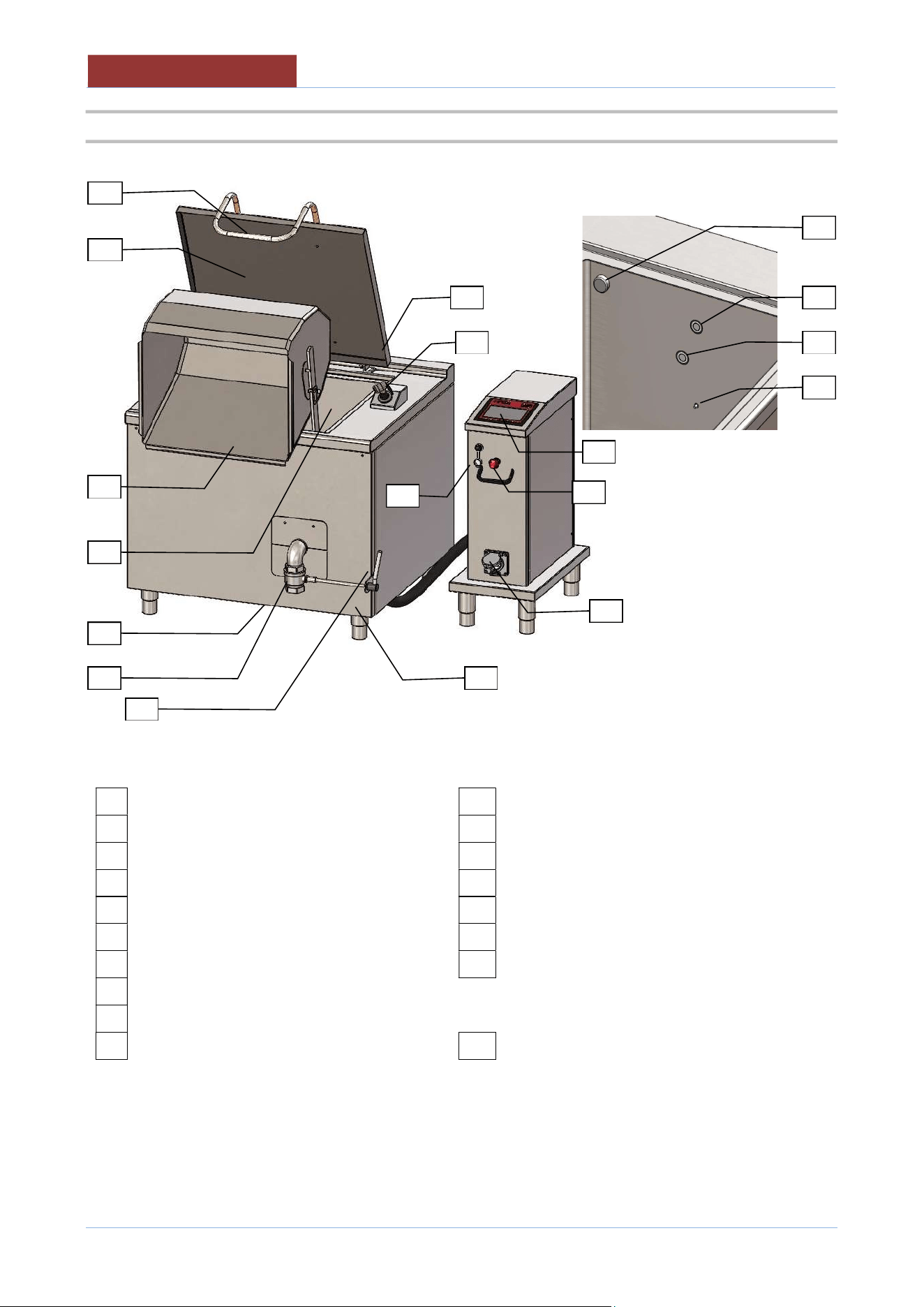
3.4 OPERATING PARTS
Internal side of the pan
01
Technical Data Plate
11
Overflow drain
02
Emergency button
12
Temperature probe in the pan
03
USB slot
13
Lower level probe (for heating)
04
Touch Screen
14
Upper level probe (automatic level control)
05
Cooking pan
15
Nozzle load water in the pan
06
Basket
16
Chimney flue (only mod.UCMPDG..)
07
Lid
17
Socket (only mod.UCPM..-..L)
08
Lid handle
09
Drain valve
OPTIONAL
10
Drain valve lever
20
Shower
08
15
06
14
13
12
03
01
02
09
07
16
04
10
11
17
20
05
TECHNICAL DATA
05
-
UCPMDG
-
DIMU
-
00
-
EN
13
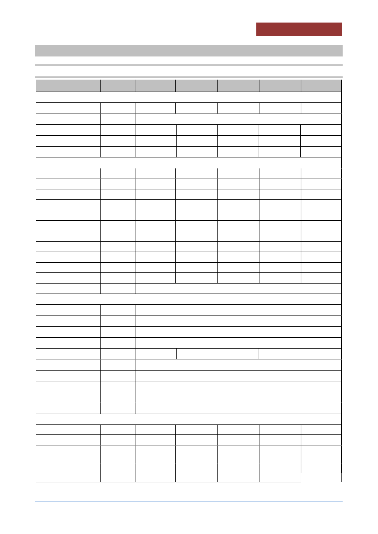
4 TECHNICAL DATA
4.1 TECHNICAL DATA UCPMDG1-.. ; UCPMDG1-..L
UCPMDG
1-32 1-48 1-48L 1-64 1-64L
TECHNICAL DATA (DIMEMSIONS)
Equipment dim.A Inches 31.50 39.37 39.37 47.24 47.24
Equipment dim.B Inches 35.43
Equipment dim.H1 Inches 38.84 38.84 44.74 38.84 44.74
Equipment dim.H Inches 35.43 35.43 41.34 35.43 41.34
Equipment dim.H2 Inches 70.87 70.87 72.44 70.87 72.44
TECHNICAL DATA (FUNCTIONALITY)
Nr.tank
nr.
1
1
1
1
1
Pan dimension A Inches 19.69 27.56 27.56 35.43 35.43
Pan dimension B
Inches
25.20
25.20
25.20
25.20
25.20
Pan dimension H Inches 16.54 16.54 16.54 16.54 16.54
Overvall volume
Gallons
32
48
48
64
64
Nr.Baskets nr. 1 1 1 1 1
Basket dimension A
Inches
15.75
23.62
23.62
31.50
31.50
Basket dimension B Inches 18.90 18.90 18.90 18.90 18.90
Basket dimension H
Inches
18.11
18.11
18.11
18.11
18.11
Volume load basket Gallons 13 19 19 25 25
Dried pasta load
lbs
26÷33
40÷51
40÷51
53÷66
53÷66
Temperature °F (°C) 20÷110
TECHNICAL DATA (INSTALLATION)
Electric power ** kW See tab.ELECTRICAL SPEFICATIONS
(E) Voltage/Input ** V 2 PH. 208V 60Hz ; 2 PH. 220 V 60Hz ; 2 PH. 240 V 60Hz
(E) Conduit Ø" 1/2"
IPX IPX 4
Gas power BTU/HR 85,500 121,500 154,000
(G) Gas connection Ø" 3/4 " NPT
(B) Water pressure PSI (kPa) 25-50 (170-345)
(B) Water inlet Ø" 1/2"
(T) Overflow Ømm Ø 40
Sound level dbA < 70
TECHNICAL DATA (STORAGE/MOVEMENT)
Packaging dim.A
Inches 37 45 45 53 53
Packaging dim.B
Inches 45 45 45 45 45
Packaging dim.H
Inches
59
59
59
59
59
Volume
ft³
57
69
69
81
81
Net weight lbs 421 485 485 540 540
Gross weight lbs 509 606 606 672 672
**Verify on rating plate .
05
-
UCPMDG
-
DIMU
-
00
-
EN
TECHNICAL DATA
14
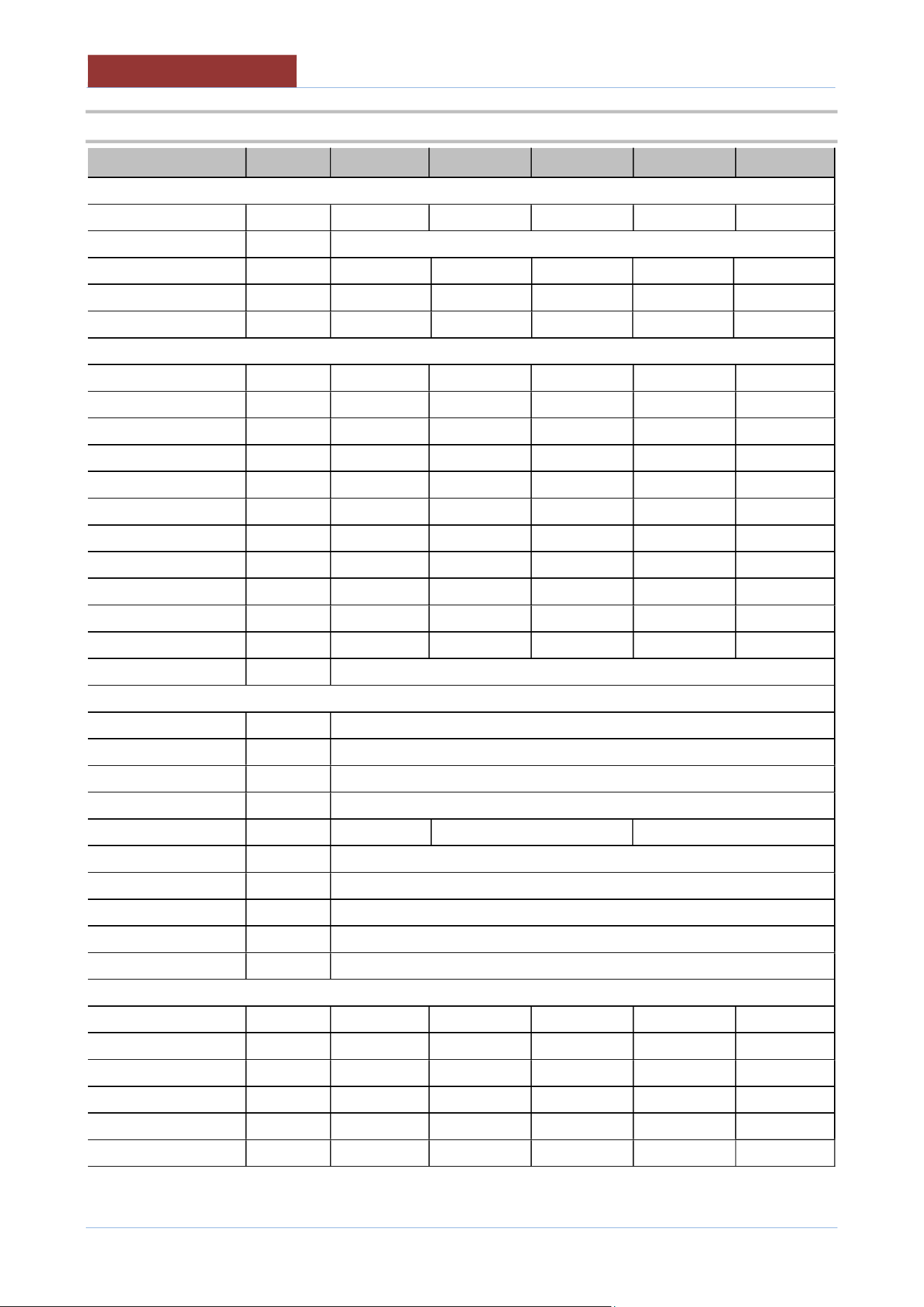
4.2 TECHNICAL DATA UCPMDG2-.. ; UCPMDG2-..L
UCPMDG
2-32 2-48 2-48L 2-64 2-64L
TECHNICAL DATA (DIMEMSIONS)
Equipment dim.A Inches 62.99 78.74 78.74 94.49 94.49
Equipment dim.B Inches 35.43
Equipment dim.H1 Inches 38.84 38.84 44.74 38.84 44.74
Equipment dim.H Inches 35.43 35.43 41.34 35.43 41.34
Equipment dim.H2 Inches 70.87 70.87 72.44 70.87 72.44
TECHNICAL DATA (FUNCTIONALITY)
Nr.tank nr. 2 2 2 2 2
Pan dimension A Inches 19.69 27.56 27.56 35.43 35.43
Pan dimension B Inches 25.20 25.20 25.20 25.20 25.20
Pan dimension H Inches 16.54 16.54 16.54 16.54 16.54
Overvall volume Gallons NR.2X32
NR.2X48 NR.2X48 NR.2X64 NR.2X64
Nr.Baskets nr. 2 2 2 2 2
Basket dimension A Inches 15.75 23.62 23.62 31.50 31.50
Basket dimension B Inches 18.90 18.90 18.90 18.90 18.90
Basket dimension H Inches 18.11 18.11 18.11 18.11 18.11
Volume load basket Gallons
NR.2x13
NR.2x19
NR.2x19
NR.2x25
NR.2x2
5
Dried pasta load lbs
(26÷33)x2
(40÷51)x2
(40÷51)x2
(53÷66)x2
(53÷66)x2
Temperature °F (°C) 68÷230 (20÷110)
TECHNICAL DATA (INSTALLATION)
Electric power ** kW See tab.ELECTRICAL SPEFICATIONS
(E) Voltage/Input ** V 2 PH. 208V 60Hz ; 2 PH. 220 V 60Hz ; 2 PH. 240 V 60Hz
(E) Conduit Ø" 1/2"
IPX IPX 4
Gas power BTU/HR NR.2X 85,500 NR.2X 121,500 NR.2X 154,000
(G) Gas connection Ø" 3/4 " NPT
Water pressure PSI (kPa) 25-50 (170-345)
Water inlet Ø" 1/2"
Overflow Ømm Ø 40
Sound level dbA < 70
TECHNICAL DATA (STORAGE/MOVEMENT)
Packaging dim.A Inches 69 84 84 100 100
Packaging dim.B Inches 45 45 45 45 45
Packaging dim.H Inches 59 59 59 60 60
Volume ft³ 105 130 130 155 155
Net weight lbs 783 893 893 1036 1036
Gross weight lbs 937 1080 1080 1235 1235
**Verify on rating plate .
TECHNICAL DATA
05
-
UCPMDG
-
DIMU
-
00
-
EN
15
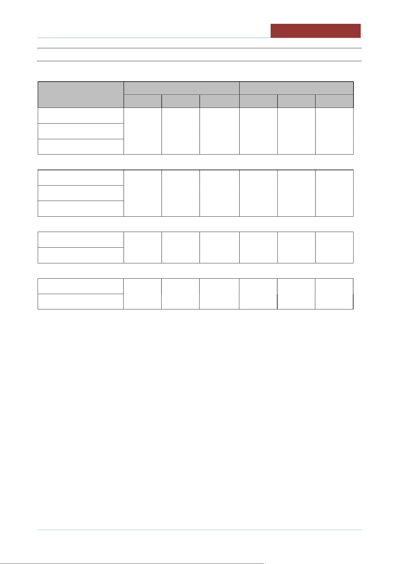
4.3 ELECTRICAL SPECIFICATIONS
MODEL
208 V 220V ; 240 V
Phase kW Amps Phase kW Amps
UCPMDG1-32
2 0.8 4.0 2 0.8 3.5
UCPMDG1-48
UCPMDG1-64
UCPMDG2-32
2 1.6 8.0 2 1.6 7.0
UCPMDG2-48
UCPMDG2-64
UCPMDG1-48L
2 2.3 10.5 2 2.3 10.0
UCPMDG1-64L
UCPMDG2-48L
2 4.6 21.0 2 4.6 20.0
UCPMDG2-64L
05
-
UCPMDG
-
DIMU
-
00
-
EN
TECHNICAL DATA
16
4.4 GAS INLET PRESSURES
GAS REQUIREMENT TABLE Type of gas
Natural Propane
Operating gas pressure in W.C. (mbar) 7.0 (17.4) 11.0 (27.4)
Min.Supply gas pressure in W.C. (mbar) 6.0 (14.9) 9.0 (22.4)
Max.Supply gas pressure in W.C. (mbar) 10.5 (26.1) 13.0 (32.3)
Warning: if the supply pressure is lower than “ Min.Supply gas pressure”, the icon appears in the display
and the heating does not activate.
Contact your gas company for correct supply line sizes.
Warning: if the supply pressure exceeds “ Max.Supply gas pressure”, a pressure regulator must be installed, to
provide a maximum of 10,5” W.C (for natural gas) or 13” W.C (for propane gas) gas pressure to the gas control valve.
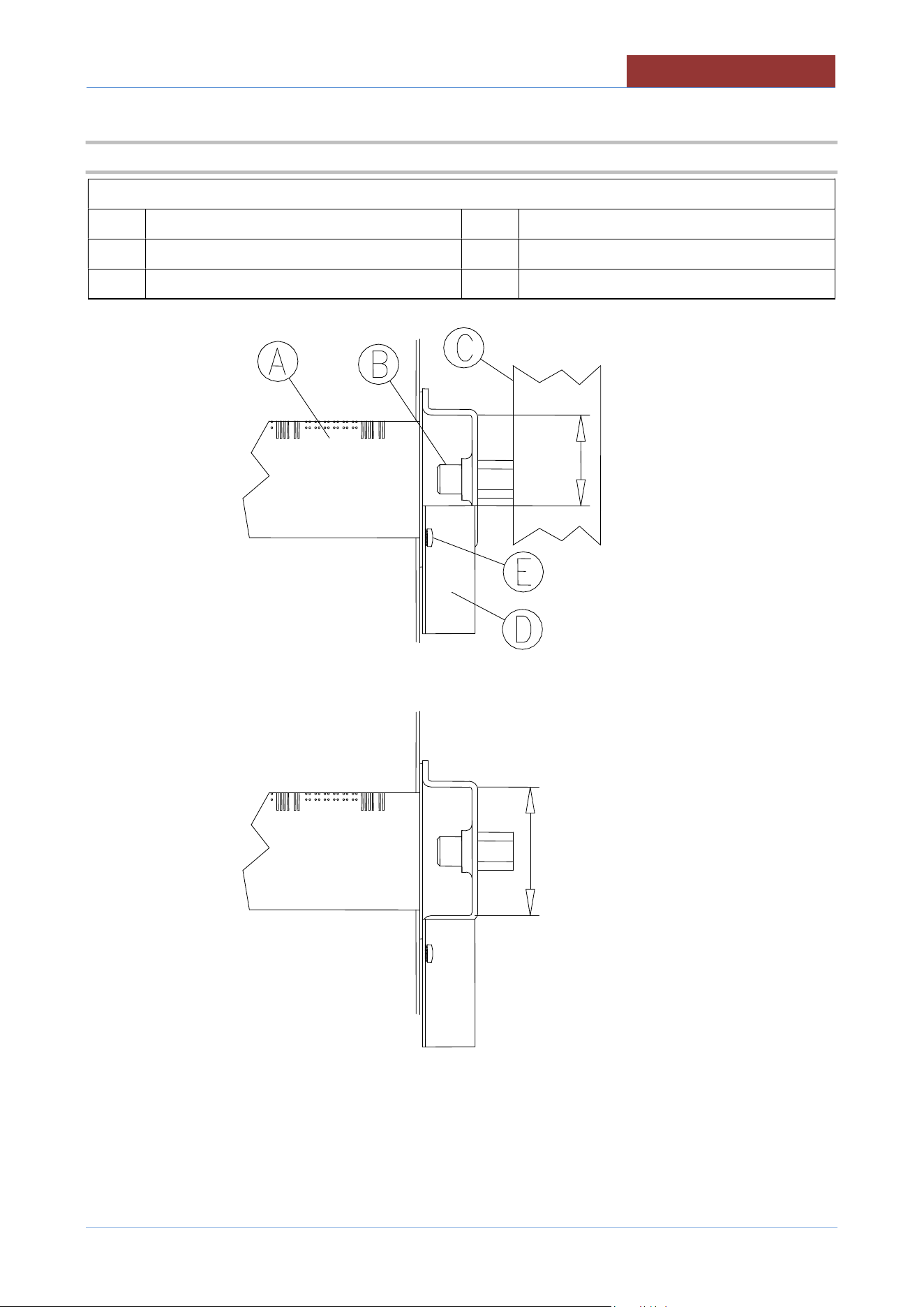
4.5 GAS MANIFOLD PRESSURE; NOZZLES;PRIMARY AIR DISTANCE
UCPMDG1-.. ; 1-..L ; 2-.. ; 2-..L 32 48 64
Rated heating power BTU/HR 85,500 121,500 154,000
Minimum heating power BTU/HR 61,500 85,500 107,500
MANIFOLD PRESSURE
Natural gas in W.C. (mbar)
6.3 (15.8) 6.2 (15.5) 5.9 (14.8)
Propane gas in W.C. (mbar)
10.5 (26.2) 10.4 (25.9) 10.4 (25.9)
NOZZLES
(Nr.x
Ø)
Natural gas
Ø 1/100 mm
6
x
175
8
x
185
10
x
195
Propane gas
Ø 1/100 mm
6
x
115
8
x
120
10
x
120
PRIMARY AIR DISTANCE
(H)
Natural gas
Inches (
mm
)
0.157 (4)
0.157 (4)
0.157 (4)
Propane gas
Inches (
mm
)
1 (25)
1 (25)
1 (25)
MANIFOLD PRESSURE
AT
MINIMUM HEATING POWER
Natural gas in W.C. (mbar)
3.5 (8.6) 3.4 (8.5) 3.3 (8.3)
Propane gas in W.C. (mbar)
5.4 (13.5) 5.5 (13.8) 5.4 (13.5)
TECHNICAL DATA
05
-
UCPMDG
-
DIMU
-
00
-
EN
17
4.6 FIG. MAIN BURNER – PRIMARY AIR REGULATION
LEGEND:
A Burner D Air regulation square
B Injector (tab."GAS DATA") E Square lock screws
C Injector pipe H See tab."GAS DATA"
05
-
UCPMDG
-
DIMU
-
00
-
EN
TECHNICAL DATA
18
4.7 FIG. GAS CONTROL VALVE (826)
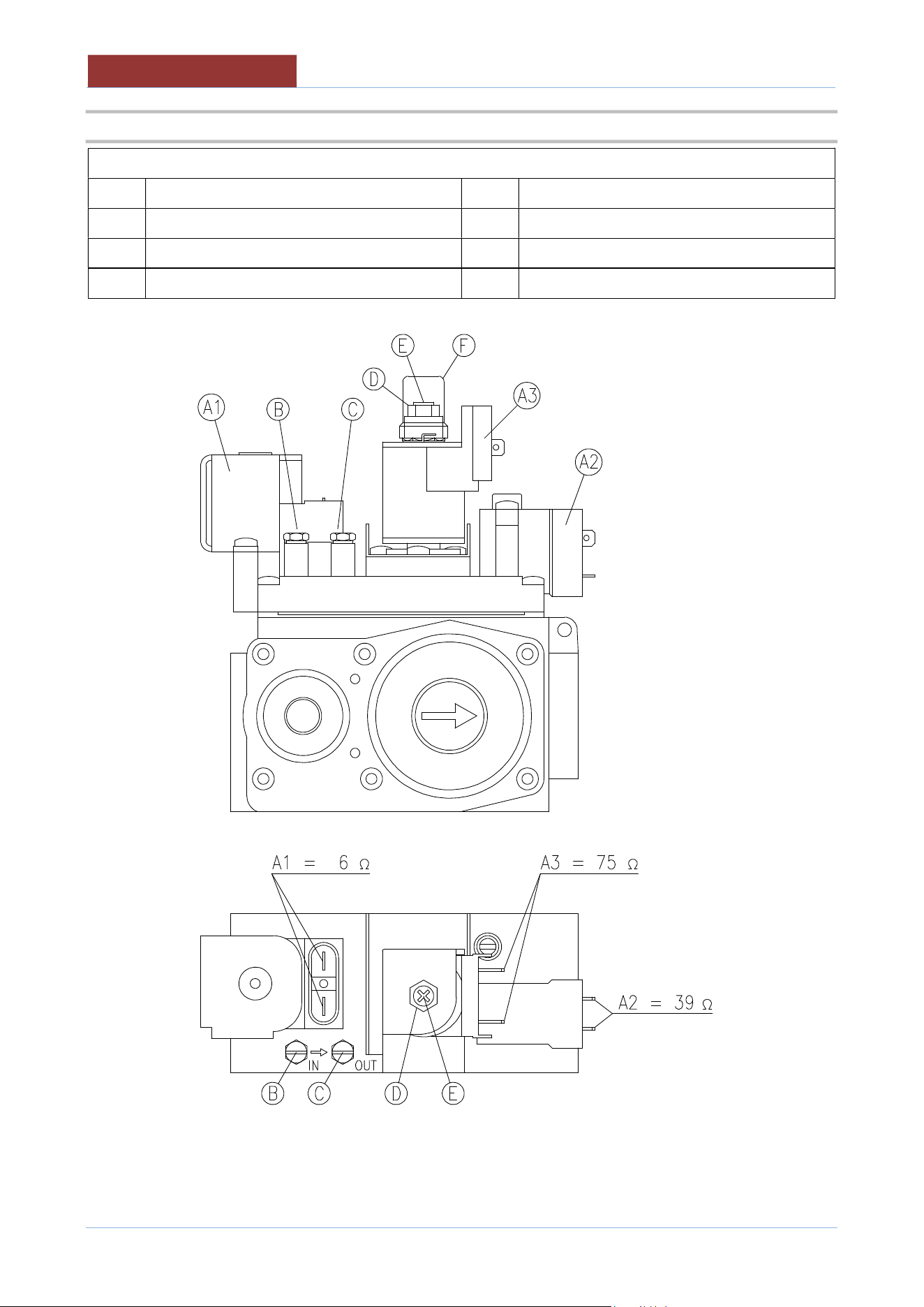
LEGEND:
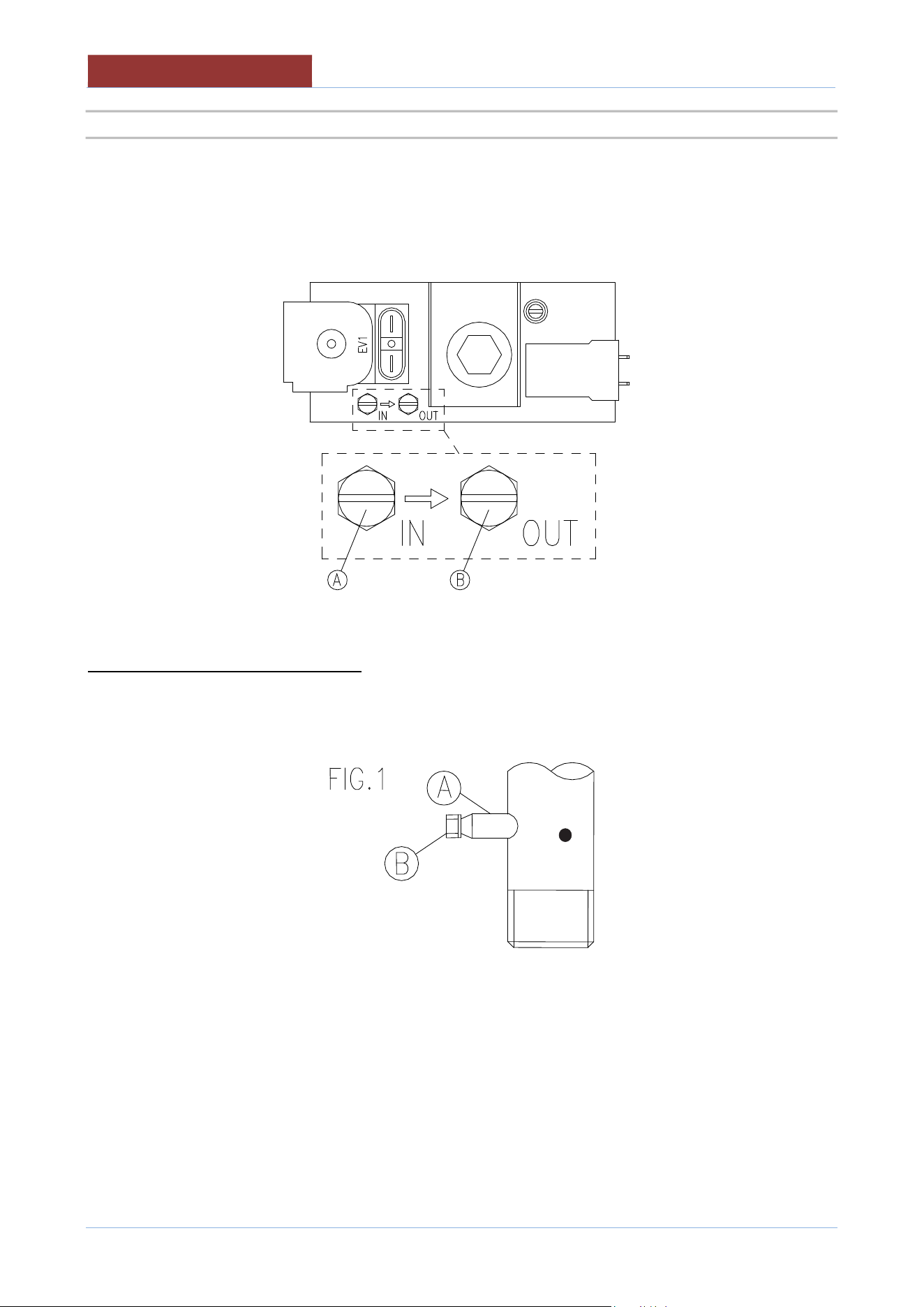
A1 Coil 6 Ω (EV1) C Outlet pressure intake (manifold pressure)
A2 Coil 39 Ω (EV2) D Max. regulation screw
A3 Coil 75 Ω (EV2) E Min. regulation screw
B
Inlet pressure intake (supply pressure)
F
Cap protecting regulation screws
Attention:
to measure the manifold pressure at minimum power (pressure intake C), with the flame on, disconnect the
connector of coil A3.
CONNECTION DRAWINGS
05
-
UCPMDG
-
DIMU
-
00
-
EN
19
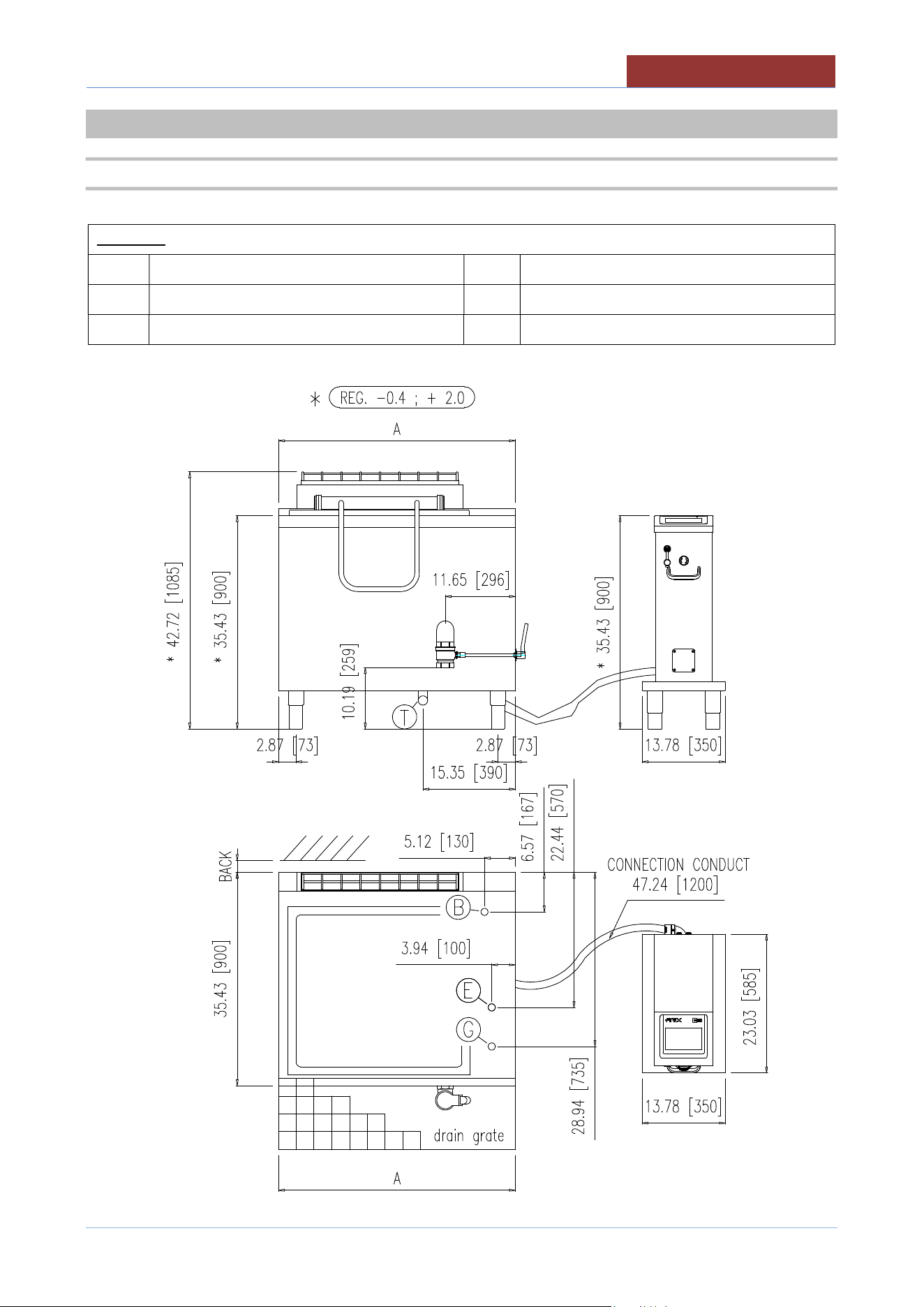
5 CONNECTION DRAWINGS
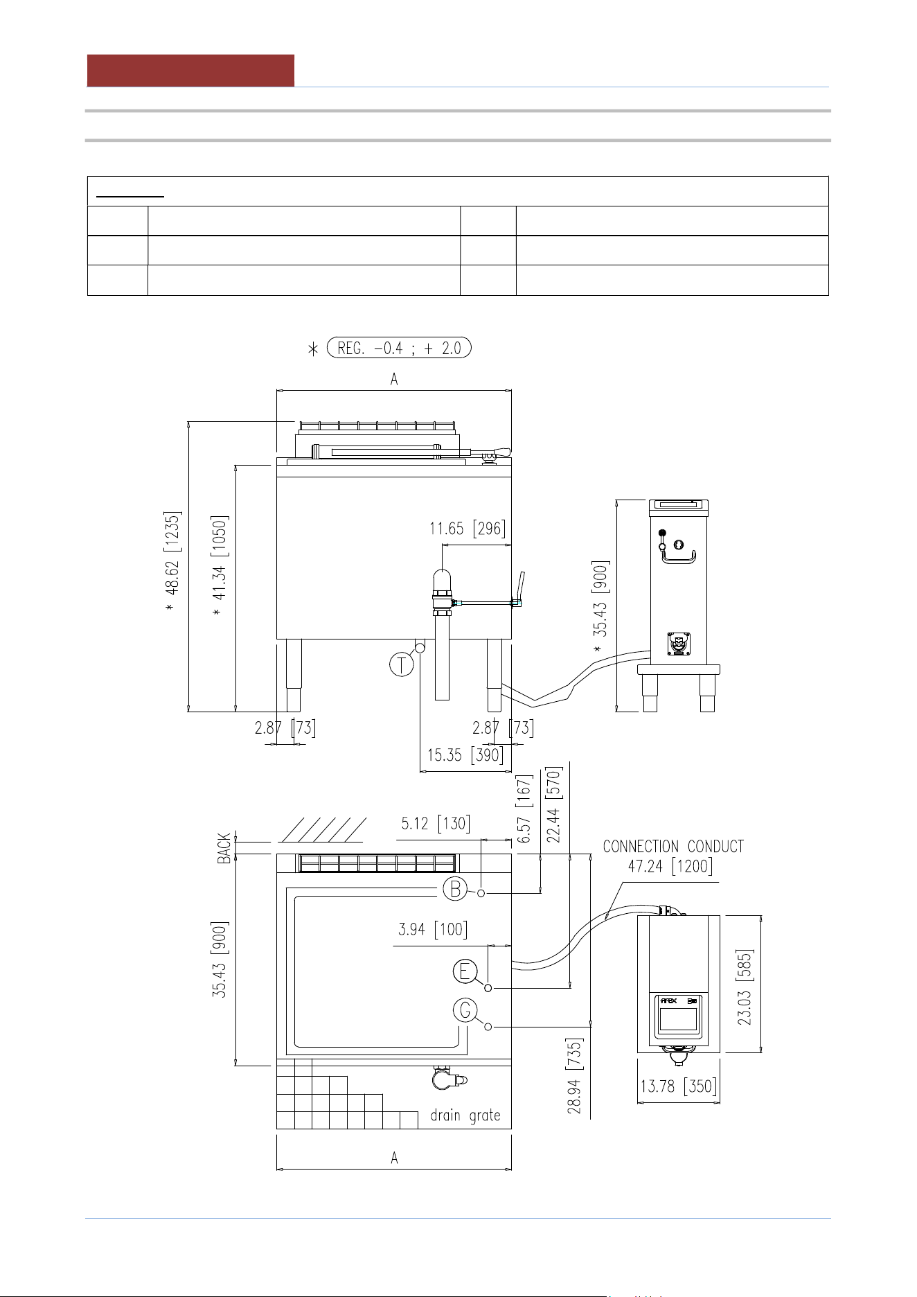
5.1 PLANT CONNECTION UCPMDG1..
LEGEND:
E Electrical connection (Conduit 1/2”) B Water connection
G
Gas connection
T
Overflow drain pan
BACK
See “CLEARANCE REQUIREMENTS”
05
-
UCPMDG
-
DIMU
-
00
-
EN
CONNECTION DRAWINGS
20
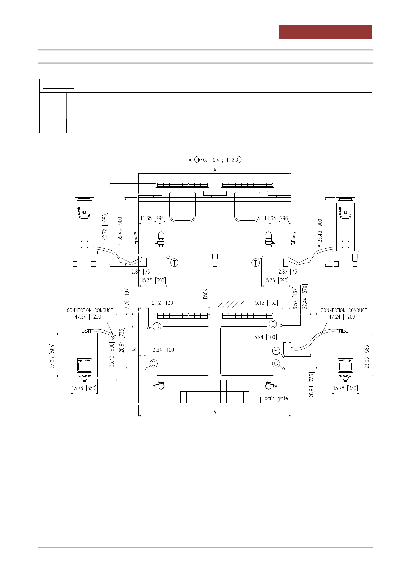
5.2 PLANT CONNECTION UCPMDG1-..L
LEGEND:
E Electrical connection (Conduit 1/2”) B Water connection
G Gas connection T Overflow drain pan
BACK
See “CLEARANCE REQUIREMENTS”
CONNECTION DRAWINGS
05
-
UCPMDG
-
DIMU
-
00
-
EN
21
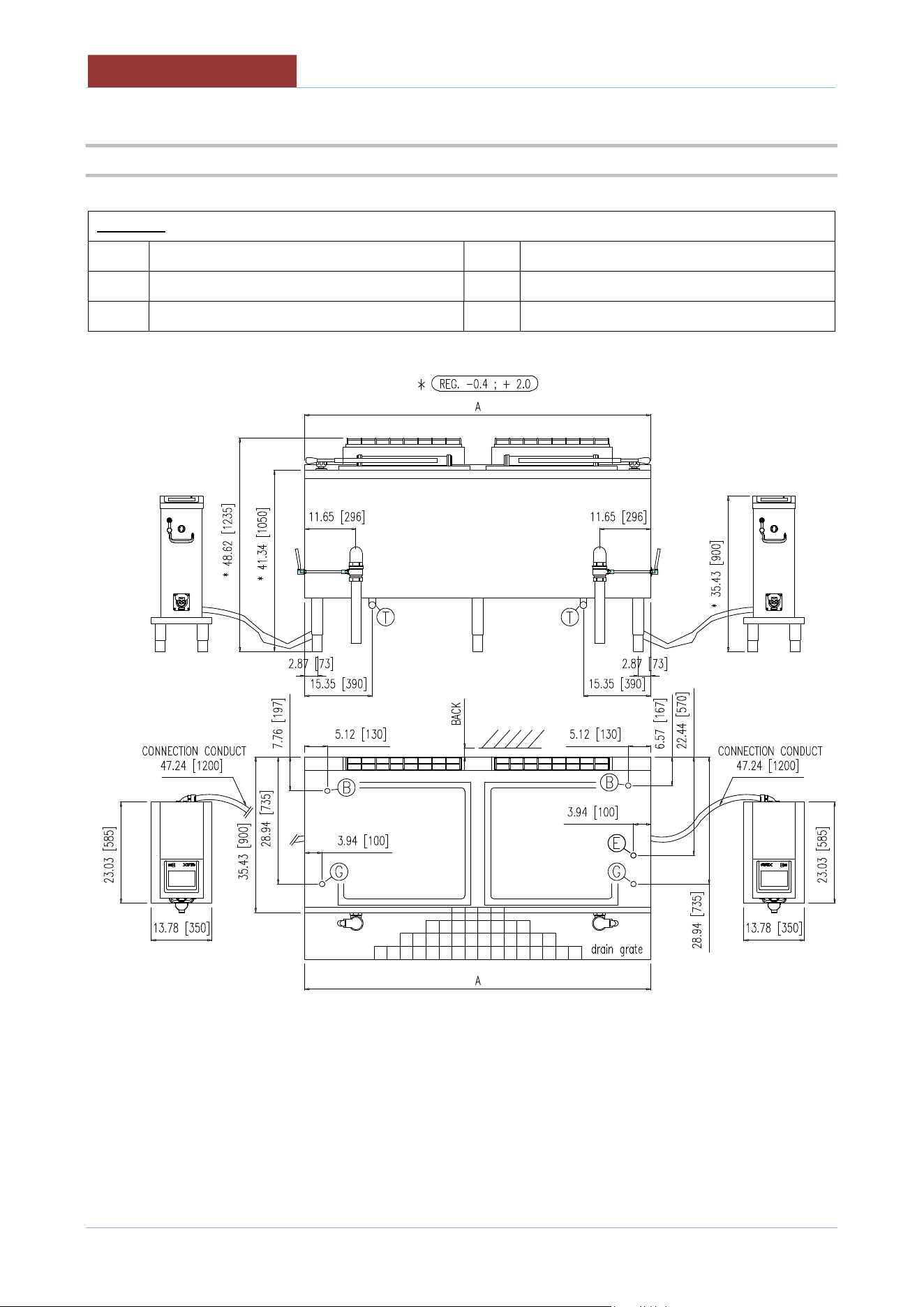
5.3 PLANT CONNECTION UCPMDG2-..
LEGEND:
E Electrical connection (Conduit 1/2”) B Water connection
G Gas connection T Overflow drain pan
BACK
See “CLEARANCE REQUIREMENTS”
05
-
UCPMDG
-
DIMU
-
00
-
EN
CONNECTION DRAWINGS
22
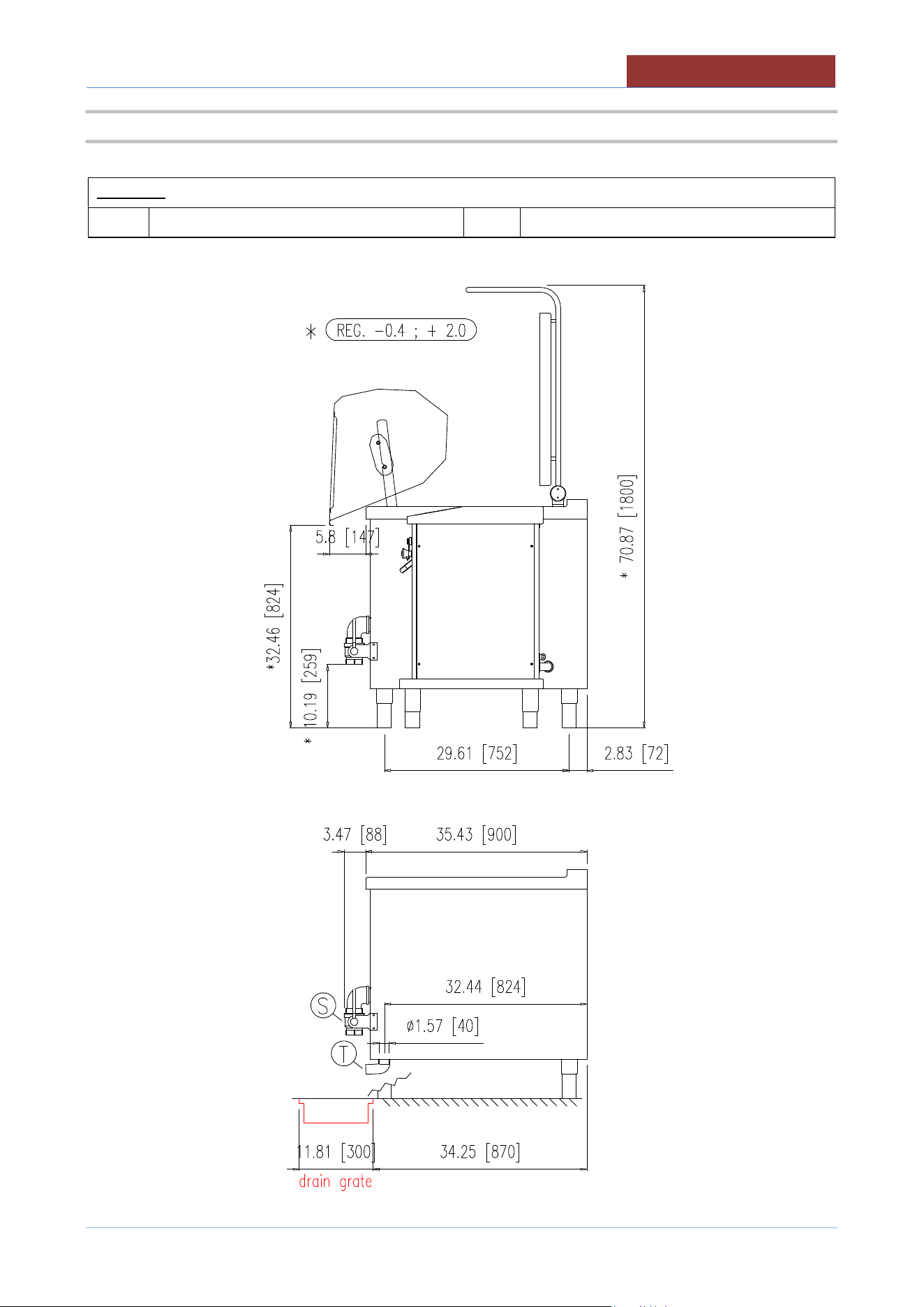
5.4 PLANT CONNECTION UCPMDG2-..L
LEGEND:
E Electrical connection (Conduit 1/2”) B Water connection
G Gas connection T Overflow drain pan
BACK
See “CLEARANCE REQUIREMENTS”
CONNECTION DRAWINGS
05
-
UCPMDG
-
DIMU
-
00
-
EN
23
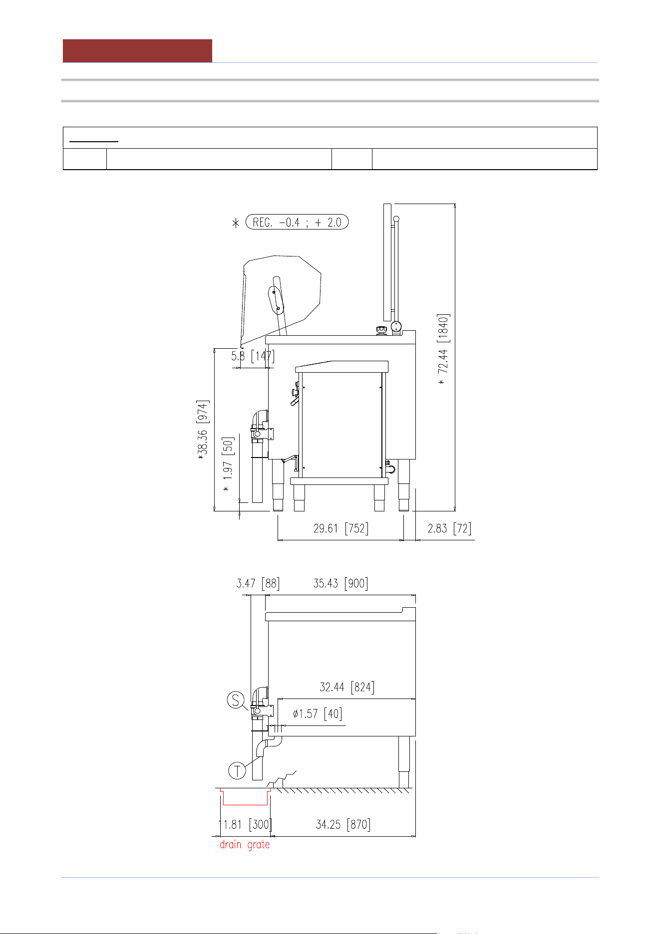
5.5 SIDE VIEW WITH DRAIN UCPMDG1-.. ; UCPMDG2..
LEGEND:
S Tank drain T Overflow drain pan
05
-
UCPMDG
-
DIMU
-
00
-
EN
CONNECTION DRAWINGS
24
5.6 SIDE VIEW WITH DRAIN UCPMDG1-..L ; UCPMDG2..L
LEGEND:
S Tank drain T Overflow drain pan
CONNECTION DRAWINGS
05
-
UCPMDG
-
DIMU
-
00
-
EN
25
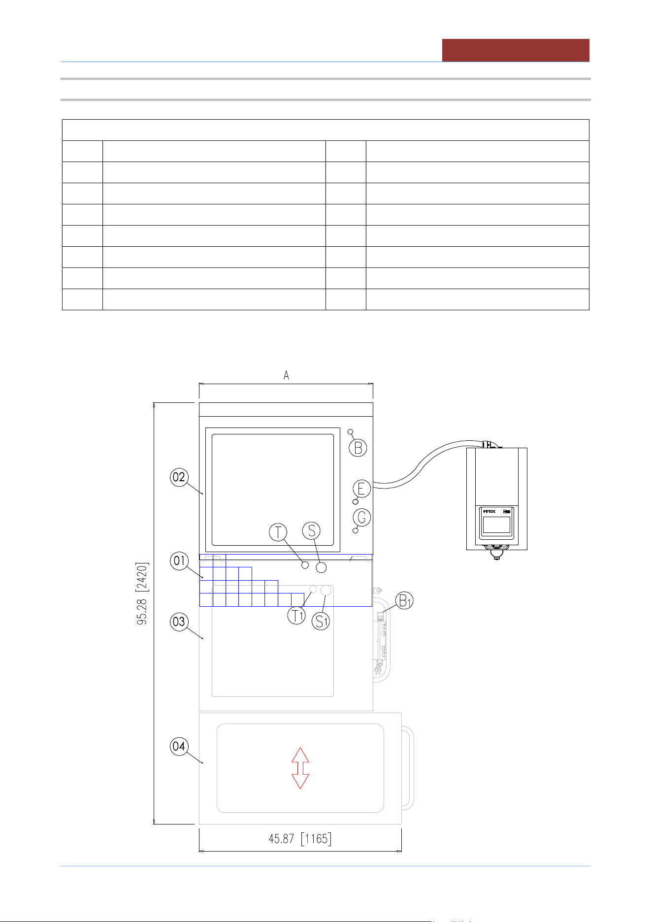
5.7 PLANT CONNECTION LINE COOK & CHILL 1 TANK (UCPMDG1-..L)
LEGENDA:
01 Grilled floor drain E Electrical connection (UCPMDG1-..L)
02 Multicooker (UCPMDG1-..L) G Gas connection (UCPMDG1-..L)
03 Tank for cooling (mod.UBAVR..DX) B Water connection (UCPMDG1-..L)
04 Trolley 3 gn1/1 (mod.UBACC1010) S Pan drain (UCPMDG1-..L)
T Overflow drain pan (UCPMDG1-..L)
B1 * Cold Water connection
S1 * Cooling tank drain
T1 * Overflow cooling tank
* See manual 05-UBAVR-DIMU-00-EN
05
-
UCPMDG
-
DIMU
-
00
-
EN
CONNECTION DRAWINGS
26
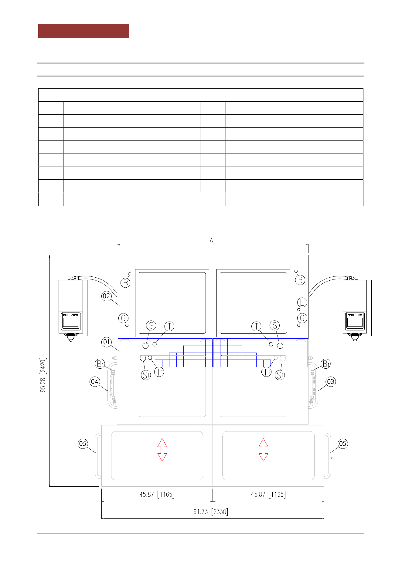
5.8 PLANT CONNECTION LINE COOK & CHILL 2 TANK (UCPMDG2-..L)
LEGENDA:
01 Grilled floor drain E Electrical connection (UCPMDG2-..L)
02 Multicooker (UCPMDG2-..L) G Gas connection (UCPMDG2-..L)
03 Tank for cooling (mod.UBAVR..DX) B Water connection (UCPMDG2-..L)
04 Tank for cooling (mod.UBAVR..SX) S Pan drain (UCPMDG2-..L)
05 Trolley 3 gn1/1 (mod.UBACC1010) T Overflow drain pan (UCPMDG2-..L)
B1 * Cold Water connection
S1 * Cooling tank drain
T1 * Overflow cooling tank
* See manual 05-UBAVR-DIMU-00-EN
CONNECTION DRAWINGS
05
-
UCPMDG
-
DIMU
-
00
-
EN
27
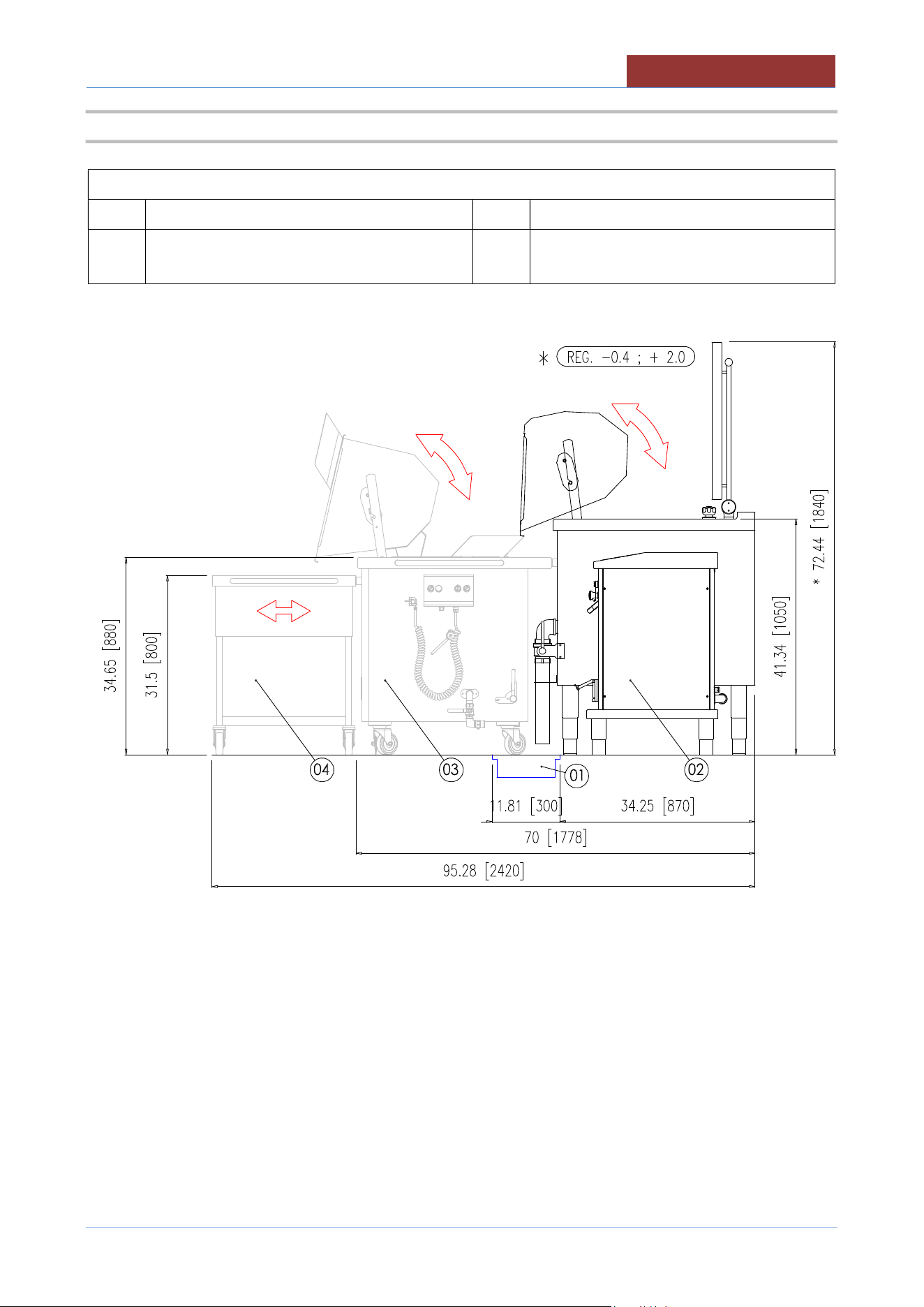
5.9 SIDE VIEW LINE COOK & CHILL 1/2 TANK (UCPMDG1-..L ; UCPMDG2..L)
LEGENDA:
01 Grilled floor drain 03 Tank for cooling (mod.UBAVR..DX/SX)
02 Multicooker (UCPMDG1-..L or UCPMDG2-
..L)
04 Trolley 3 gn1/1 (mod.UBACC1010)
05
-
UCPMDG
-
DIMU
-
00
-
EN
TRANSPORT
, STORAGE, UNPACKING
28
6 TRANSPORT, STORAGE, UNPACKING
6.1 TRANSPORT
The movement of the machine must be performed by a qualified operator for use of
lifting and transport equipment in accordance with the laws of the country of the user
of the machine.
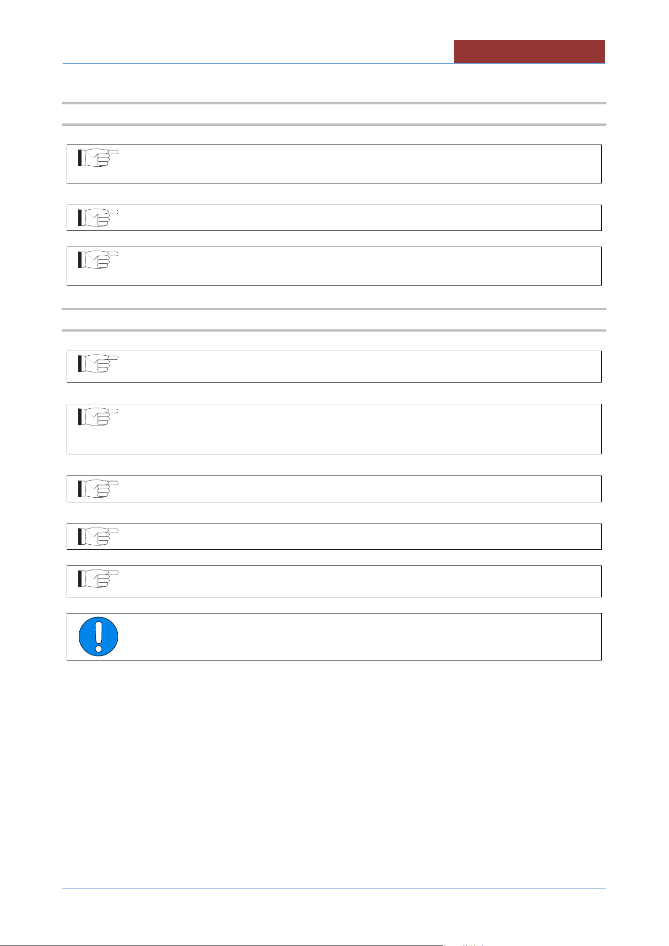
The machine can be transported with a normal means (forklift or transpallet)capable of supporting its weight
and size (see.tab. "TECHNICAL DATA").
Always check the correct balance of the weight of the machine (B = center of gravity)
to prevent unexpected movement or dropping to the floor of the car with damage to
people or things around you.
For transport on pallets, Fig.1
For transport without pallets, Fig.2
When unpacking and subsequent handling, pay particular attention to the control
columns. Do not allow the connection conduit to be pulled!
TRANSPORT, STORAGE, UNPACKING
05
-
UCPMDG
-
DIMU
-
00
-
EN
29
6.2 STORAGE
Store the appliance in a closed environment protected against atmospheric agents.
Keep the appliance away from humidity and temperature ranges
Protect the appliance from shocks and stresses
Ensure that the appliance is in contact with corrosive substances
6.3 RECEIPT AND UNPACKING
Upon receipt of the machine check that the packaging is undamaged. If it does not withdraw
the conditional commodity producing photographic evidence of any apparent damage.
After removing the packaging, check that the appliance is undamaged.In case of
visible damage, do not connect the appliance but contact the sales outlet
immediately.
Check for the presence of individual components with packing lists.
Remove from the panels of the machine the protective film PVC .
Before disposing of the packaging materials make sure that they do not contain machine
elements
(accessory; tools; documentation, etc)
Dispose of the packaging components in accordance with the regulations in force on
waste disposal.
05
-
UCPMDG
-
DIMU
-
00
-
EN
INSTALLATION
30
7 INSTALLATION
7.1 INSTALLATION CODES AND STANDARDS
Installation must conform with local codes, or in the absence of local codes, with the National Fuel Gas Code,
ANSI Z223.1/NFPA 54, or the Natural Gas and Propane Installation Code, CSA B149.1, as applicable.
1. The appliance and its individual shut off valve must be disconnected from the gas supply piping
system during any pressure testing of that system at pressures in excess of ½ psi (3.5 kPa).
2. The appliance must be isolated from the gas supply piping system by closing its individual
manual shut off valve during any pressure testing of the gas supply piping system at test
pressures equal to or less than ½ psi (3.5 kPa).
Electrical grounding must be provided in accordance with local codes, or in the absence of local
codes, with the National Electrical Code, ANSI/NFPA 70, or the Canadian Electrical Code, CSA
C22.2, as applicable.
The electrical diagram is located on the inside of side panel of right hand console.
7.2 REQUIREMENTS FOR THE INSTALLATION SITE
The room in which the appliance is to operate must be well ventilated.
The appliance belongs to the installation class A1 (no direct connection of a chimney of flue exhaust system is
required), so it is very important for the environment in which it is installed to be well-aired and provided with all
the safety openings prescribed for its power.
VENTILATION
The appliance are only to be installed under a ventilation hood in a room which has provisions for
adequate make up air.
Information on the construction and installation of ventilating hoods may be obtained from the
standard for “Vapor Removal from Cooking Equipment”, NFPA No. 96 (latest edition), available
from the National Fire Protection Association, Batterymarch Park, Quincy, MA, USA, 02269.
The gas shut off valve, the electrical isolating switch and the water shutoff valves must
both be located near to the appliance, within easy reach for the user.
INSTALLATION
05
-
UCPMDG
-
DIMU
-
00
-
EN
31
7.3 POSITIONING
CLEARANCE REQUIREMENTS
This unit must be installed in accordance with the clearances shown on the rating label which is adhered to the
unit.
UCPMDG1-.. UCPMDG1-..L
CLEARANCES
Combustible construction Noncombustible construction
Back
8 “ (200 mm)
2 ” (50 mm)
Right Side 25" (635 mm) 25" (635 mm)
Left Side 0" 0"
"Suitable for installation on combustible floors"
UCPMDG2-.. UCPMDG2-..L
CLEARANCES
Combustible construction Noncombustible construction
Back
8 “ (200 mm)
2 ” (50 mm)
Right Side 25" (635 mm) 25" (635 mm)
Left Side 25" (635 mm) 25" (635 mm)
"Suitable for installation on combustible floors"
There are no particular prescriptions regarding side distances from other appliances or walls, however it is
advisable to leave enough space (20/30 “ : 50/70 cm) in case of maintenance and/or repairs.
The appliance must stand level. Small differences in level can be eliminated by screwing or
unscrewing the adjustable feet. A significantly uneven or sloping stance can affect the
operation of the appliance adversely.
Adjust the bottom foot on each leg to overcome an uneven floor.
05
-
UCPMDG
-
DIMU
-
00
-
EN
CONNECTIONS
32
8 CONNECTIONS
8.1 ELECTRICAL CONNECTION
During installation, observe the regulations provided by the local electricity company.
The appliance is supplied to operate according to the power supply indicated on
appliance's rating plate.
A separate fused disconnect switch must be supplied and installed. The appliance must be
electrically grounded by the installer.
The earthing system must be efficient.
The electric supply must match the power requirements specified on the appliance's rating
plate.
The copper wiring must be adequate to carry the required current at the rated voltage.
The connection point is indicated in the "PLANT CONNECTION"
Ensure main power is turned off before connecting wires.
Remove the screws of the pannel in the right side of the appliance.
Remove the right pannel. Remove the electrical box cover.
Fix the conduit in the prepared hole.
Insert the cable through the conduit. Carefully connect the conductors to the corresponding terminals. The
earth conductor must be longer than the other conductors, so as to disconnect last in the event of a strong pull
of the cable.
Reassemble the electrical box cover and secure it with screws.
Reassemble the right pannel and secure it with screws.
Any damage caused by water/steam infiltration or insects, due to the machine panels
not being closed (after installation or maintenance) shall void any warranty claims.
CONNECTIONS
05
-
UCPMDG
-
DIMU
-
00
-
EN
33
8.2 WATER CONNECTION
The equipment is to be installed with adequate backflow protection to comply with
applicable federal, state, and local codes.
The water pressure in the supply network must be between the values indicated in the
"INSTALLATION TECHNICAL DATA" table.
If not, install a pressure reducer upstream of the appliance.
Before making the water connection, carefully clean the connection pipe. It is
advisable to let the water flow to clean the whole piping. Any impurities could
compromise the operation of the machine.
The diameter of the connections is indicated in "INSTALLATION TECHNICAL DATA"
The connection point is indicated in the "PLANT CONNECTION"
Install a shut-off valve upstream of the appliance, one for each water connection on the appliance, near the
appliance and in a position easily accessible by the user.
05
-
UCPMDG
-
DIMU
-
00
-
EN
CONNECTIONS
34
8.3 WATER DRAIN CONNECTION
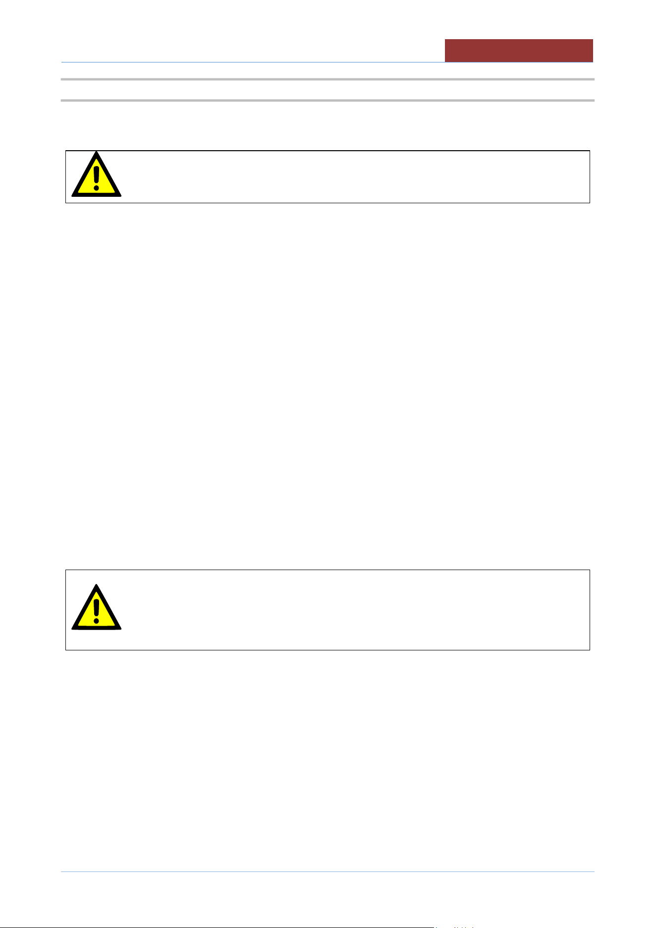
Make sure there is a drain grate, of the dimensions indicated in the “CONNECTION
DRAWING”.
In the drain grate must discharge the discharge valve (S) and an overflow (T).
WARNING!
The appliance is supplied with a drain elbow connected to the overflow device (T) to convey hot water steam
away from the appliance, to avoid it dripping into the appliance damaging its electronic circuit, therefore:
Do not remove or turn the overflow elbow .
During cooking from the overflow (T) hot water can come out.
To avoid burns:
Bring the drain as close as possible to the drain grate (fig.1 dimension “X” < 0.5 ")
Eventually, bring the drain directly into the drain grate (fig.2)
CONNECTIONS
05
-
UCPMDG
-
DIMU
-
00
-
EN
35
8.4 GAS CONNECTION
The choice of the gas piping depends on the diameter required for the type of gas, appliance and installation
and should be performed in conformity with current regulations.
The rating plate on the lower right side of the unit indicates the type of gas your unit is
equipped to burn. Do NOT connect to any other gas type.
Each unit is equipped with an internal pressure regulator .
The manifold pressure is show in table “GAS MANIFOLD PRESSURE”
An adequate gas supply is imperative.
Undersized or low pressure lines will restrict the volume of gas required for satisfactory performance.
Fluctuations of the normal supply pressure more than 20% on natural gas, and 10% on propane gas, will
create problems and affect burner operating characteristics.
The gas inlet pressure is show in table “GAS INLET PRESSURE”
With all units operating simultaneously, the manifold pressure on all units should not show any appreciable
drop.
Purge the supply line to clean out any dust, dirt, or other foreign matter before connecting the line to the unit.
It is recommended that an individual manual shut off valve be installed in the gas supply line to the unit.
Use pipe joint compound which is suitable for use with LP gas on all threaded connections. Test pipe
connections thoroughly for gas leaks.
WARNING:
All connections must be checked for leaks, after the unit has been put in operation.
Use soapy water only for testing on all gases.
Never use an open flame to check for gas leaks.
NOTICE: If applicable, the vent line from the gas appliance pressure regulator
shall be installed to the outdoors in accordance with local codes or, in the
absence of local codes, with the National Fuel Gas Code, ANSI Z223.1/NFPA 54,
or the Natural Gas and Propane Installation Code CSA B149.1, as applicable.
The diameter of the connections is shown in "TECNICAL DATA"
The point of connection is shown in the "PLANT CONNECTIONS"
05
-
UCPMDG
-
DIMU
-
00
-
EN
CONNECTIONS
36
8.4.1 CONTROL OF THE GAS PRESSURE
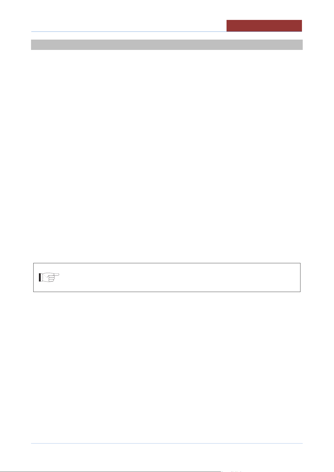
Gas pressure is measured directly in the gas valve.
A = GAS INLET PRESSURE INTAKE
B = GAS MANIFOLD PRESSURE INTAKE
ONLY FOR THE EUROPEAN MARKET
The gas inlet pressure intake is on the gas feed pipe (FIG.1 "A") (See PLANT CONNECTION).
Before connecting the gauge remove the screw of the inlet pressure intake (FIG.1 "B").
Connect the U manometer and measure the pressure with device functioning.
At the end tighten the screw of the inlet pressure intake.
COMMISSIONING AND TESTING
05
-
UCPMDG
-
DIMU
-
00
-
EN
37
9 COMMISSIONING AND TESTING
Once all the connections have been made, the appliance and the overall installation must be checked
following the directions given in this manual.
CHECK IN PARTICULAR:
That the protective film has been removed from the external surfaces;
That the panels of the machine are closed correctly;
That connections have been made in accordance with the requirements and directions indicated in this
manual;
That all safety requirements in current standards, statutory regulations and directives have been met;
That the power cable is not subjected to traction and is not in contact with hot surfaces;
That the water, gas and steam connections are tight and not subjected to traction.
Now proceed to light the appliance as directed in the instructions for use.
While the appliance is in use, voltage should not differ from the nominal voltage more than +/- 10%.
In the gas models:
Check that the flue gas exhaust is not clogged and that they are expelled without any hindrance.
Repeat "CONTROL OF THE GAS INLET PRESSURE" with the machine running.
If you have other machines connected to the main pipe of the gas, although these have to be put into
operation, to perform a correct control of of the pressure of inlet gas.
The test report must be completed in full and submitted to the customer who should
then sign in acceptance. With effect from this moment, the appliance is covered by the
manufacturer’s warranty
10 USING THE MACHINE
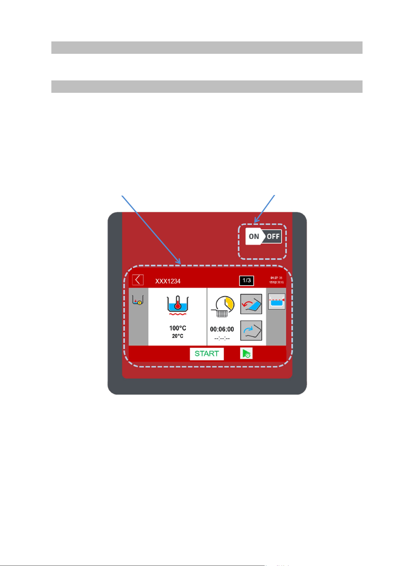
11 TOUCH SCREEN
1-On-off switch
2- 7" TFT resistive display
3- Keypad for movements (mixer, pan)
2- 7" TFT resistive display
1-On-off switch
MAIN MENU
05
-
UCPMDG
-
DIMU
-
00
-
EN
39
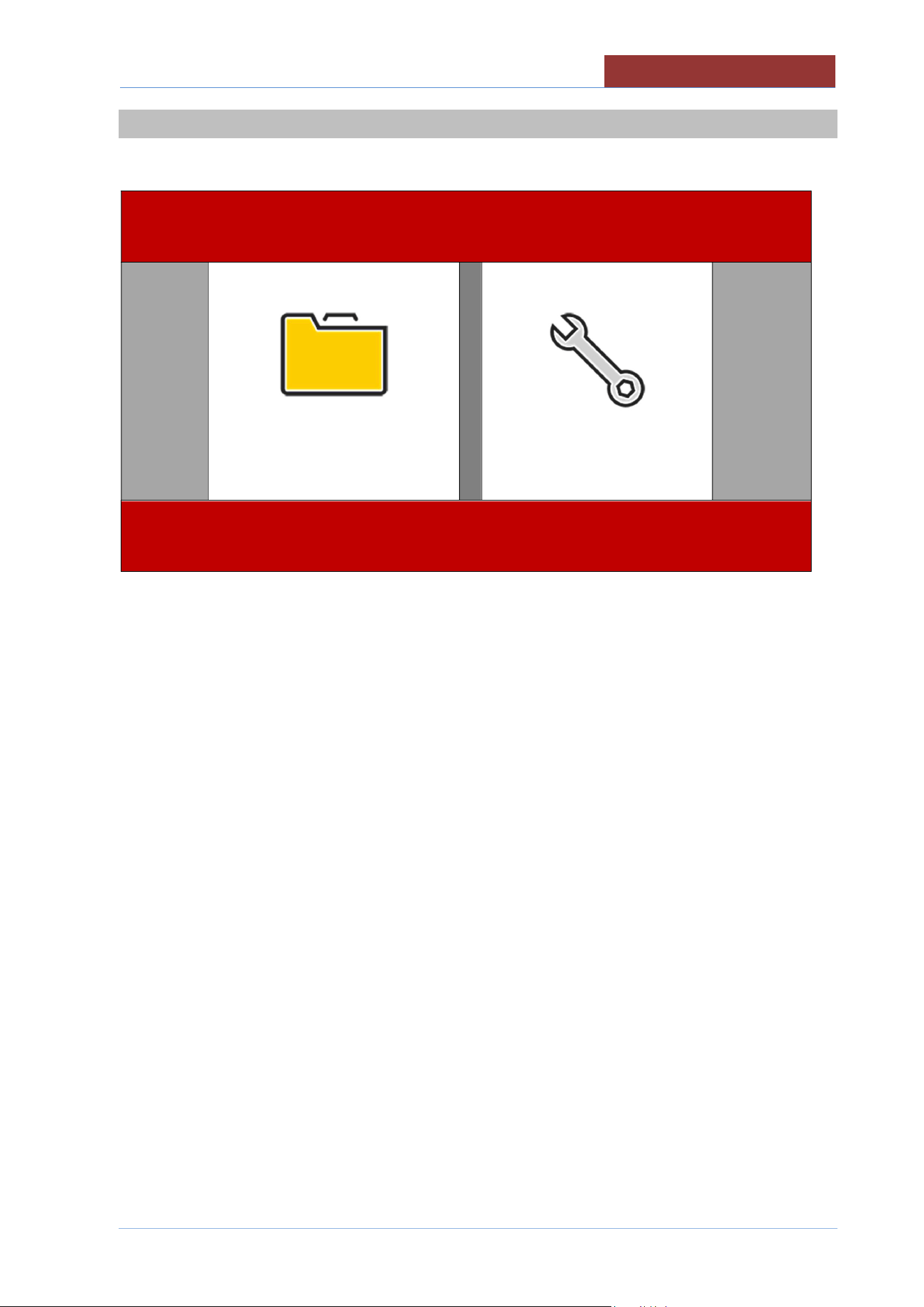
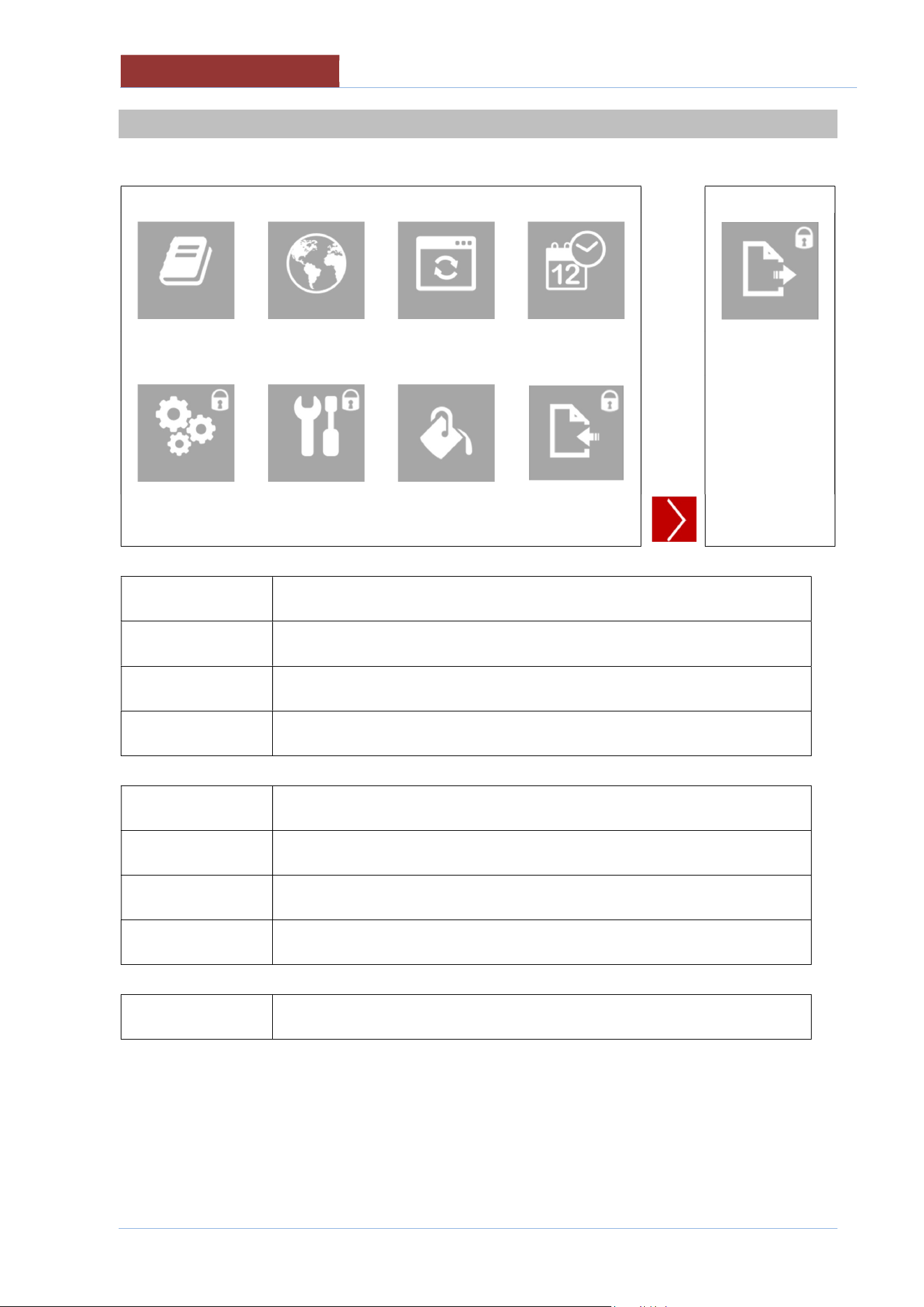
12 MAIN MENU
PROGRAMS
SETTINGS
PROGRAMS
Setting manual cooking parameters
Carrying out manual cooking
Running cooking programs
SETTINGS
Appliance setting-user;
creating-editing cooking programs
language
date-time
firmware update
colors
EXPORT (HACCP data)
Appliance setting - installer/technical assistant;
TEST I/O
Parameter setting (unit of measurement)
Import database
05
-
UCPMDG
-
DIMU
-
00
-
EN
SETTINGS MENU
40
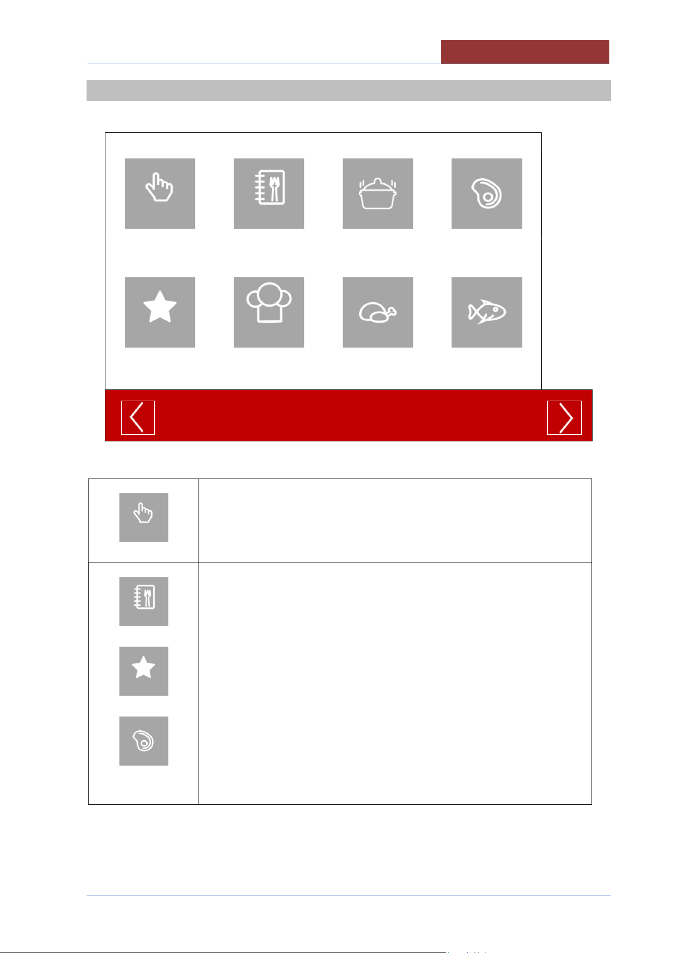
13 SETTINGS MENU
PROG
RAMS
LANGUAGES
FIRMWARE
DATE
-
HOUR
EXPORT
TEST I/0
PARAMETERS
COLORS
IMPORT
PROGRAMS
Creating-editing cooking programs
LANGUAGES
Language setting
FIRMWARE
Firmware update (from USB)
DATE-HOUR
Current Date and Time setting
TEST I/0
Test I/O board (only with password)
PARAMETERS
Parameter setting (only with password)
COLORS
Screen colour setting
IMPORT
Import database (parameters, cooking, languages, programs) only with
password.
EXPORT
Export (HACCP data).Read the instruction manual dedicated to HACCP.
PROGRAMS MENU
05
-
UCPMDG
-
DIMU
-
00
-
EN
41
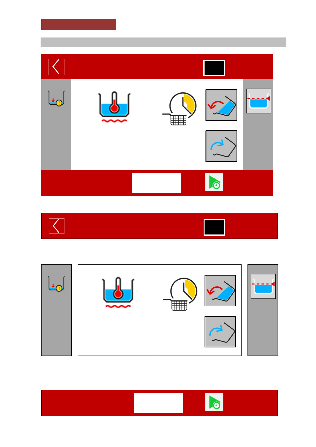
14 PROGRAMS MENU
MANUAL
ALL
SAUCES
MEAT
FAVORITES
CHEF
POULTRY
FISH
MANUAL
Setting manual cooking parameters
Carrying out manual cooking
ALL
FAVORITES
MEAT
ETC
Running cooking programs
05
-
UCPMDG
-
DIMU
-
00
-
EN
COOKING LAYOUT
42
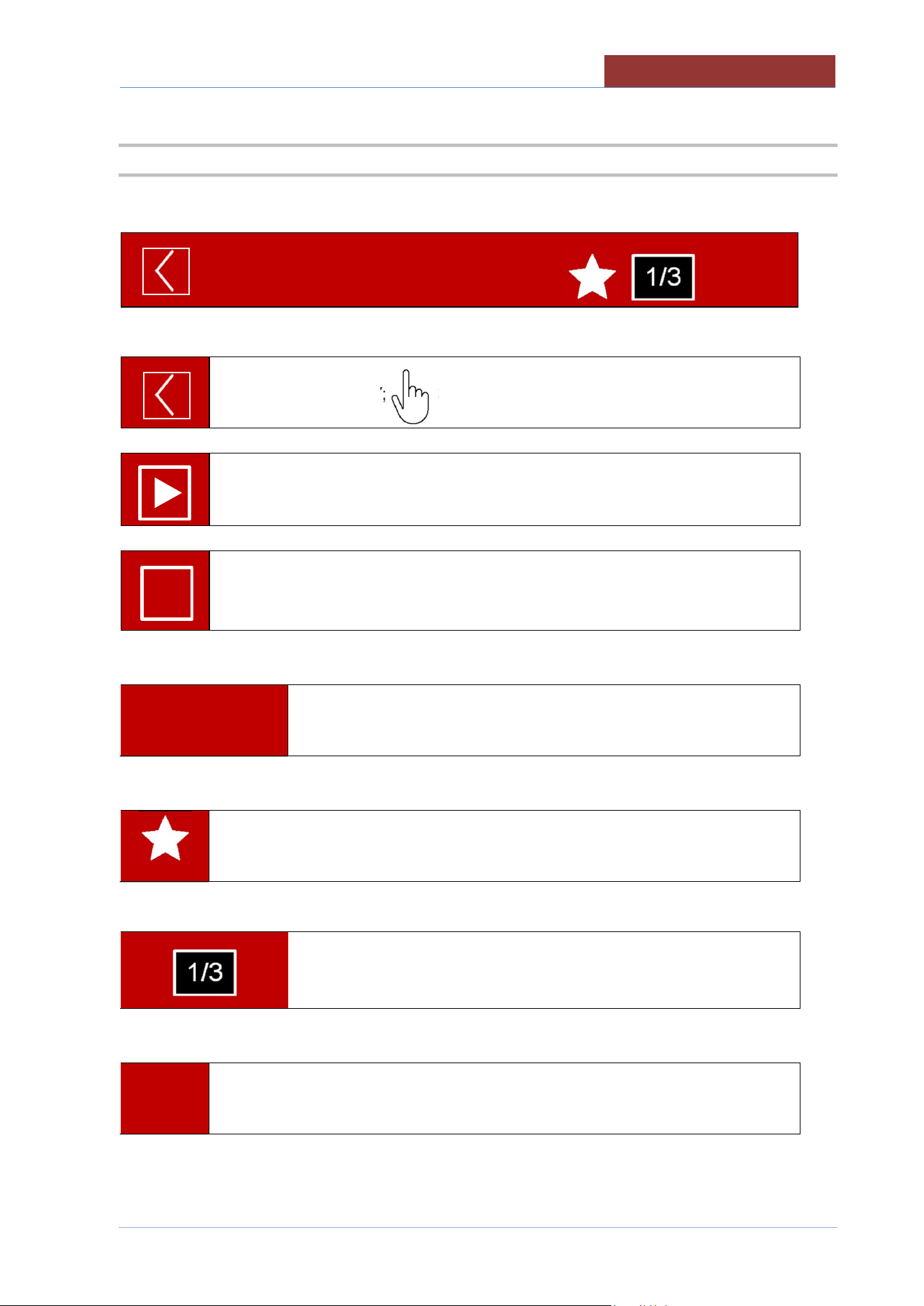
15 COOKING LAYOUT
XXX1234
01:27: 35
17/12/ 2016
100°C
20°C
00:06:00
--:--:--
STATUS BAR
XXX1234
01:27: 35
17/12/ 2016
↓ COOKING AREA
_________________________________________________________
100°C
20°C
00:06:00
--:--:--
_________
__________
↑ MESSAGE COLUMN FUNCTION COLUMN ↑
FUNCTION BAR
1/3
START
1/3
START
COOKING LAYOUT
05
-
UCPMDG
-
DIMU
-
00
-
EN
43
15.1 STATUS BAR
1
2
3 4
5
XXX1234
01:27: 35
17/12/ 2016
1
STAND-BY/RETURN KEY; 3 sec → HOME
↓
COOKING/PROGRAM IN PROGRESS.
↓
COOKING/PROGRAM IN PROGRESS (PAUSED) AWAITING ACTION.
2
XXX1234
Name of cooking program selected
3
PROGRAM IN THE LIST OF FAVOURITES (not present in manual cooking)
4
PROGRAM PHASE IN PROGRESS (not present in manual cooking)
5
01:27: 35
17/12/ 2016
CURRENT TIME AND DATE
I I
05
-
UCPMDG
-
DIMU
-
00
-
EN
COOKING LAYOUT
44
15.2 COOKING AREA
COOKING METHOD>
SETPOINT >
VALUE MEASURED>
100°C
20°C
TIME TYPE >
SETPOINT >
COUNTDOWN >
00:06:00
--:--:--
< BASKET LIFT BUTTON
< BASKET LOWERING BUTTON
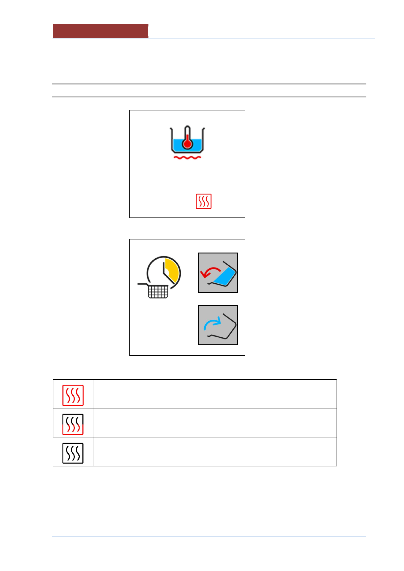
HEATING IN OPERATION
MINIMUM HEATING
HEATING OFF AS SETPOINT REACHED OR FOR WAITING (L
COLUMN ICONS)
COOKING LAYOUT
05
-
UCPMDG
-
DIMU
-
00
-
EN
45
15.3 MESSAGE COLUMN (L)
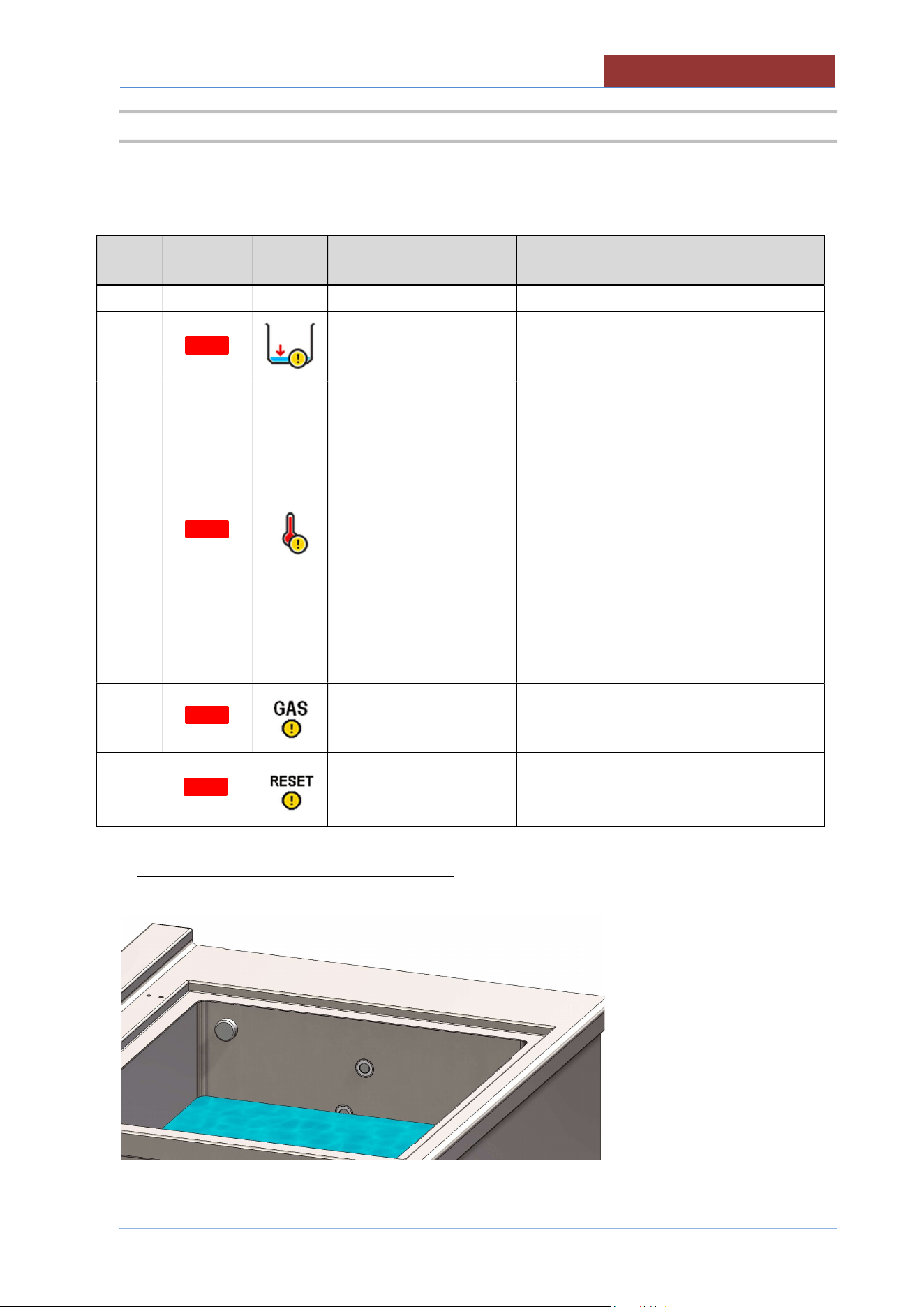
INFORMATION AND REQUESTS INDICATOR L COLUMN
buzzer
Light
Indicator
Icon Description Behaviour
A
Water level insufficient Icon present when the level of H2O in the
pan is insufficient (heating does not
activate) **.(see figure below)
A
Overtemperature on the
heating elements (only
electric model UCPMDE)
Possible presence of limestone on the
bottom of the tank.
Icon present when the safety thermostat
has been activated. To reset the alarm,
turn off the machine using the emergency
button and allow the machine to cool
down.
With the machine cold, carefully clean the
bottom of the tank from limescale.
If the message occurs again:
Request assistance from a service center.
Apply to a service centre for
assistance.
A
Insufficient gas pressure
(only gas model
UCPMDG)
Icon present when gas pressure switch
has been triggered.
A
Gas central unit reset
(only gas model
UCPMDG)
Icon present due to interruption in the gas
central unit
** MINIMUM LEVEL OF WATER FOR HEATING
Lower Level Probe
05
-
UCPMDG
-
DIMU
-
00
-
EN
COOKING LAYOUT
46
15.4 FUNCTION COLUMN (R)
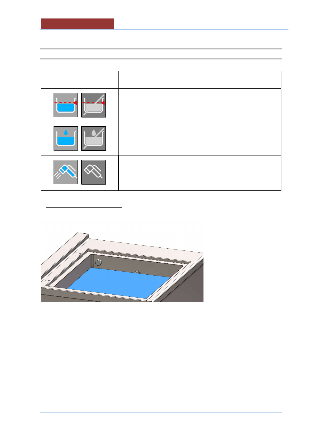
Bottom
ON OFF
Description
ON-OFF key for automatic loading H2O in tank and automatic level
control. **(see figure below)
ON-OFF key for starch skimming .
ON-OFF key for functioning shower .(optional)
In ON the operation is timed.
To change the value, press the button for 2 seconds
** AUTOMATIC LEVEL CONTROL
Upper Level Probe
COOKING LAYOUT
05
-
UCPMDG
-
DIMU
-
00
-
EN
47
15.5 FUNCTION BAR
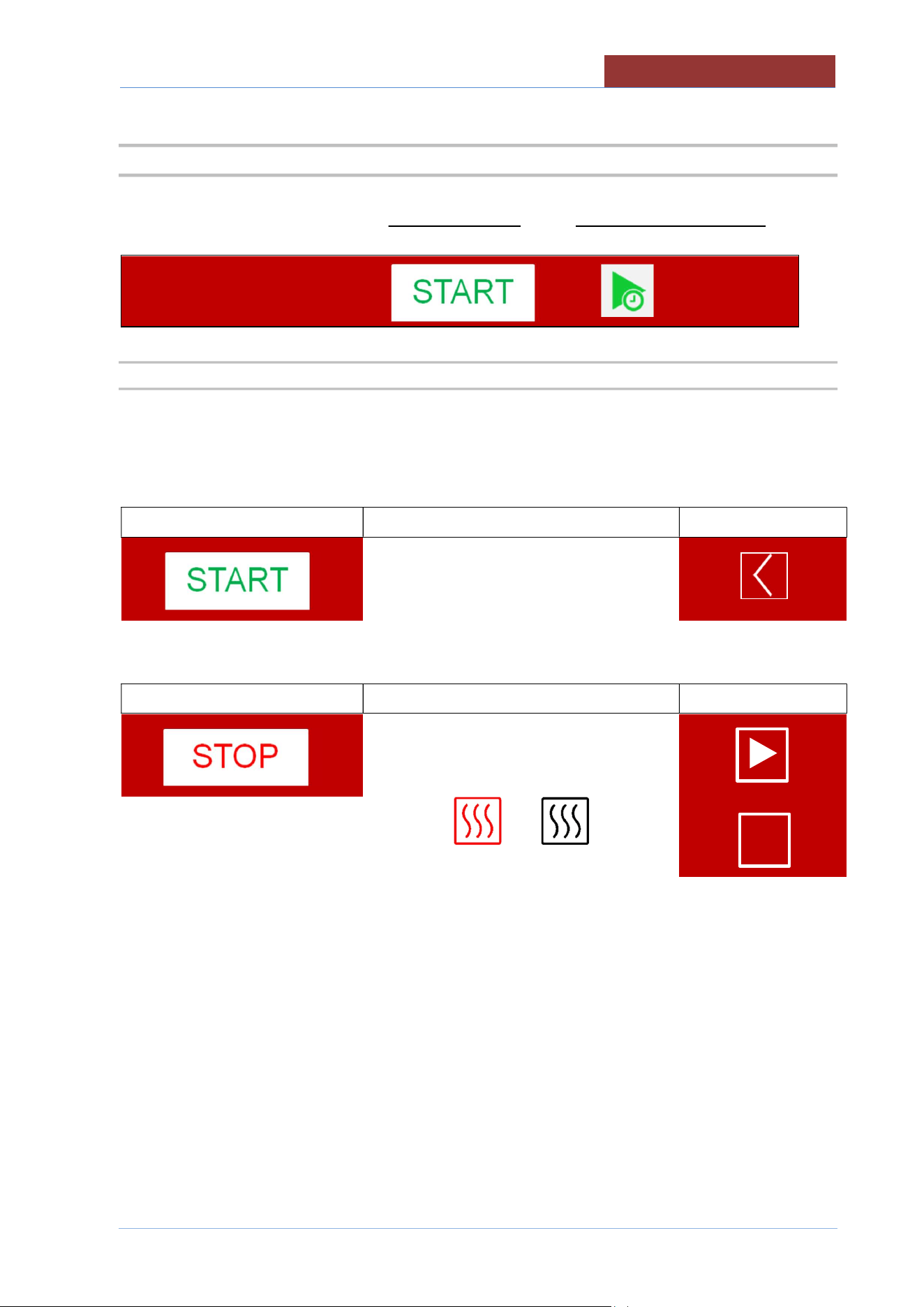
START/STOP KEY DELAYED COOKING KEY
↓ ↓
15.5.1 START-STOP KEY FOR RUNNING PROGRAMS
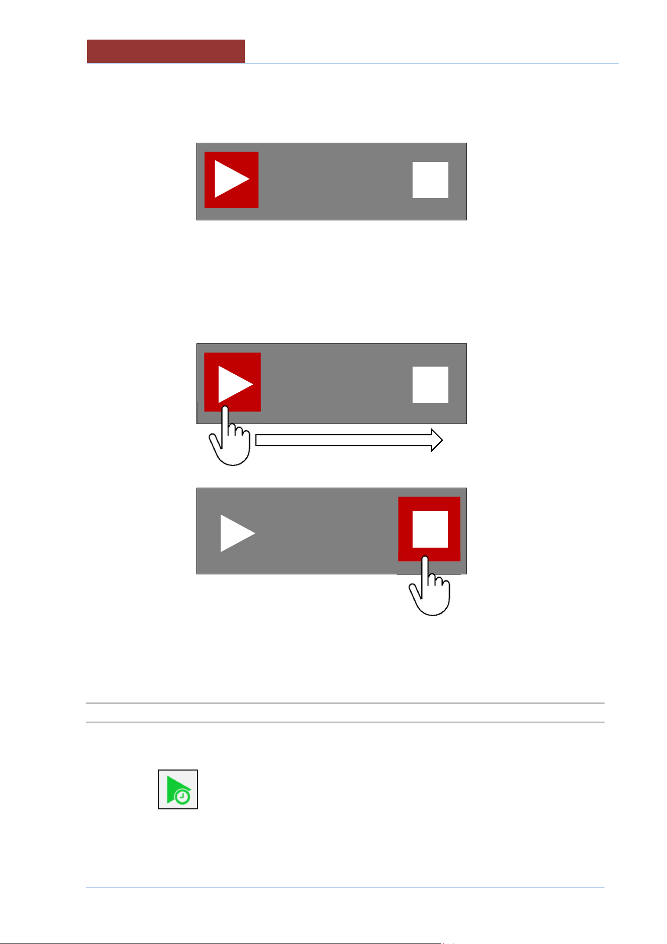
Attention: the START/STOP key indicates the action that will be performed by pressing the key!
The machine status is indicated by the icon on the top left
With key presence Machine status
icon on the top left
Machine in stand-by.
Pressing the START key starts the program and the START key becomes the STOP.
With key presence Machine status
icon on the top left
Program running.
or
I I
05
-
UCPMDG
-
DIMU
-
00
-
EN
COOKING LAYOUT
48
To avoid accidentally stopping the cooking program in progress, press the STOP key and the following
screen appears:
If the STOP key has been pressed incorrectly, wait approximately 5 seconds and you return to the
program in progress.
If instead you want to stop the program, slide the coloured square from the triangle to the square and
release the key.
The STOP key becomes START.
15.5.2 COOKING WITH DELAY TIMER KEY
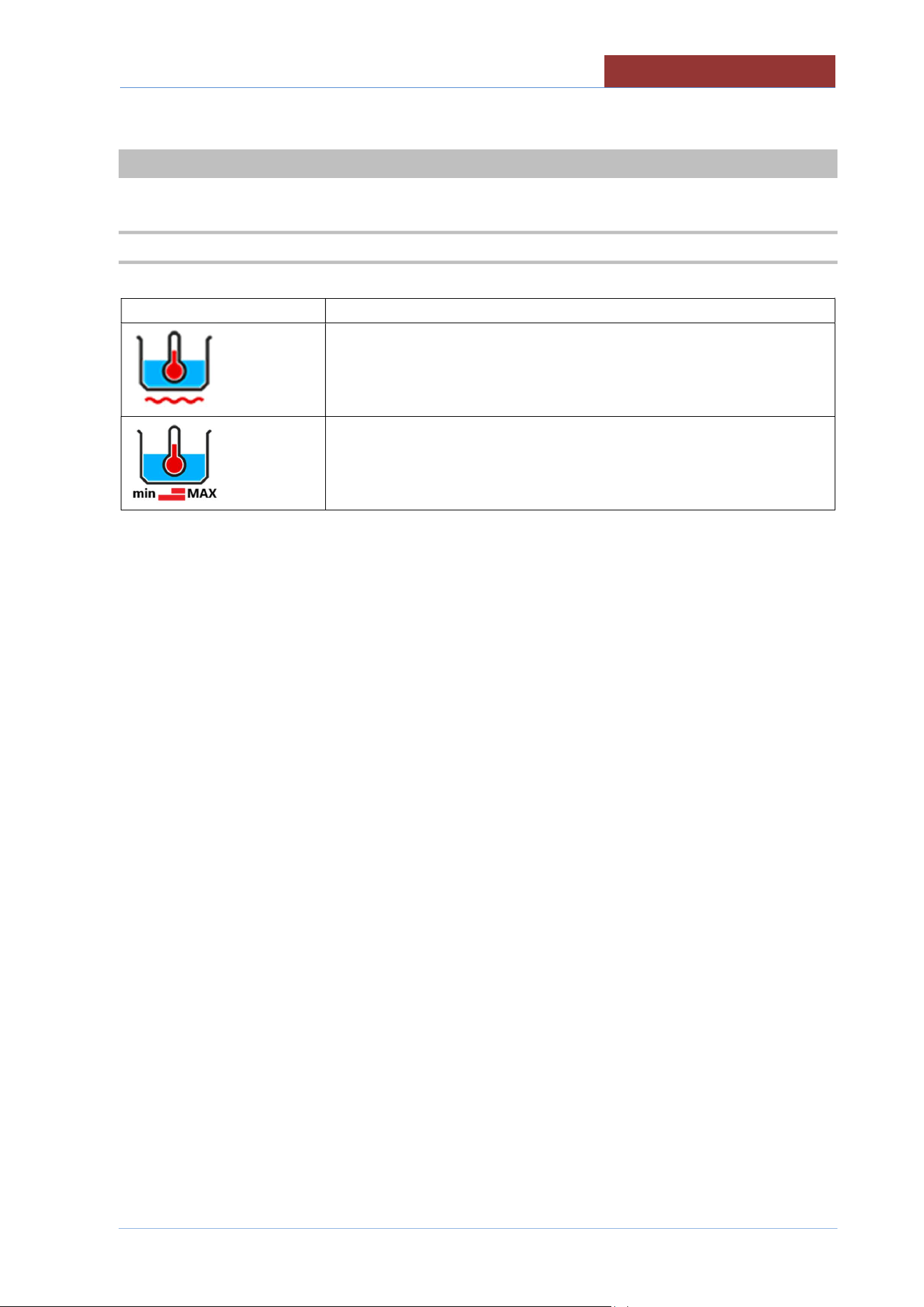
Press the key to access the settings for cooking with delay timer.
COOKING METHODS IN DETAIL
05
-
UCPMDG
-
DIMU
-
00
-
EN
49
16 COOKING METHODS IN DETAIL
16.1 COOKING
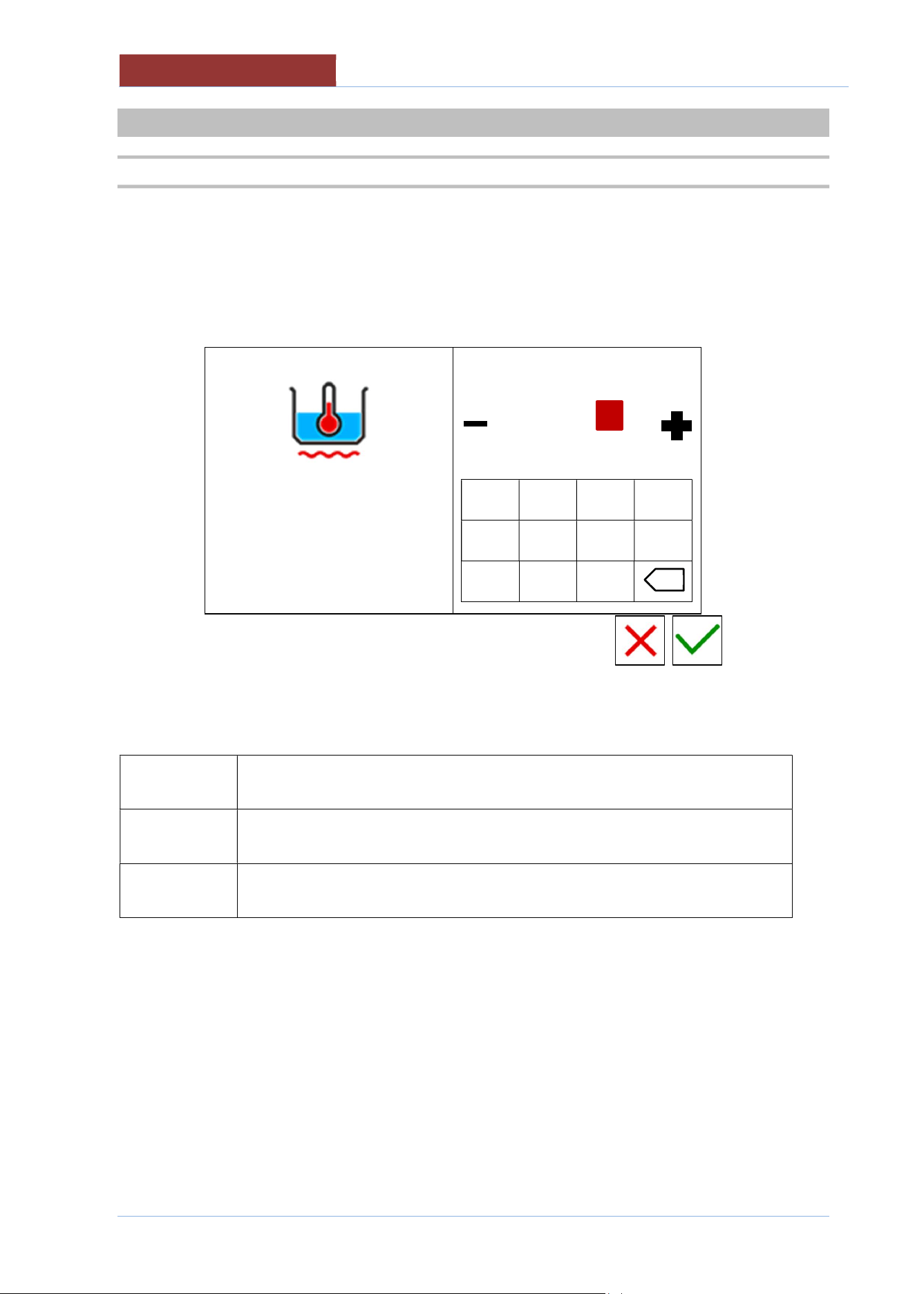
Icon
Description
For cooking in water that requires a maximum temperature of 100°C; the
temperature regulation is controlled by the sensor (PT1000) located inside the
pan, in contact with the water .
F
or cooking in water where it is required to check the boiling
intensity. It is
possible to select only the power (minimum or maximum), not the SET
temperature
05
-
UCPMDG
-
DIMU
-
00
-
EN
SETTING SETPOINT
PARAMETERS
50
17 SETTING SETPOINT PARAMETERS
17.1 SETTING SETPOINT VALUES WITH THE KEYPAD
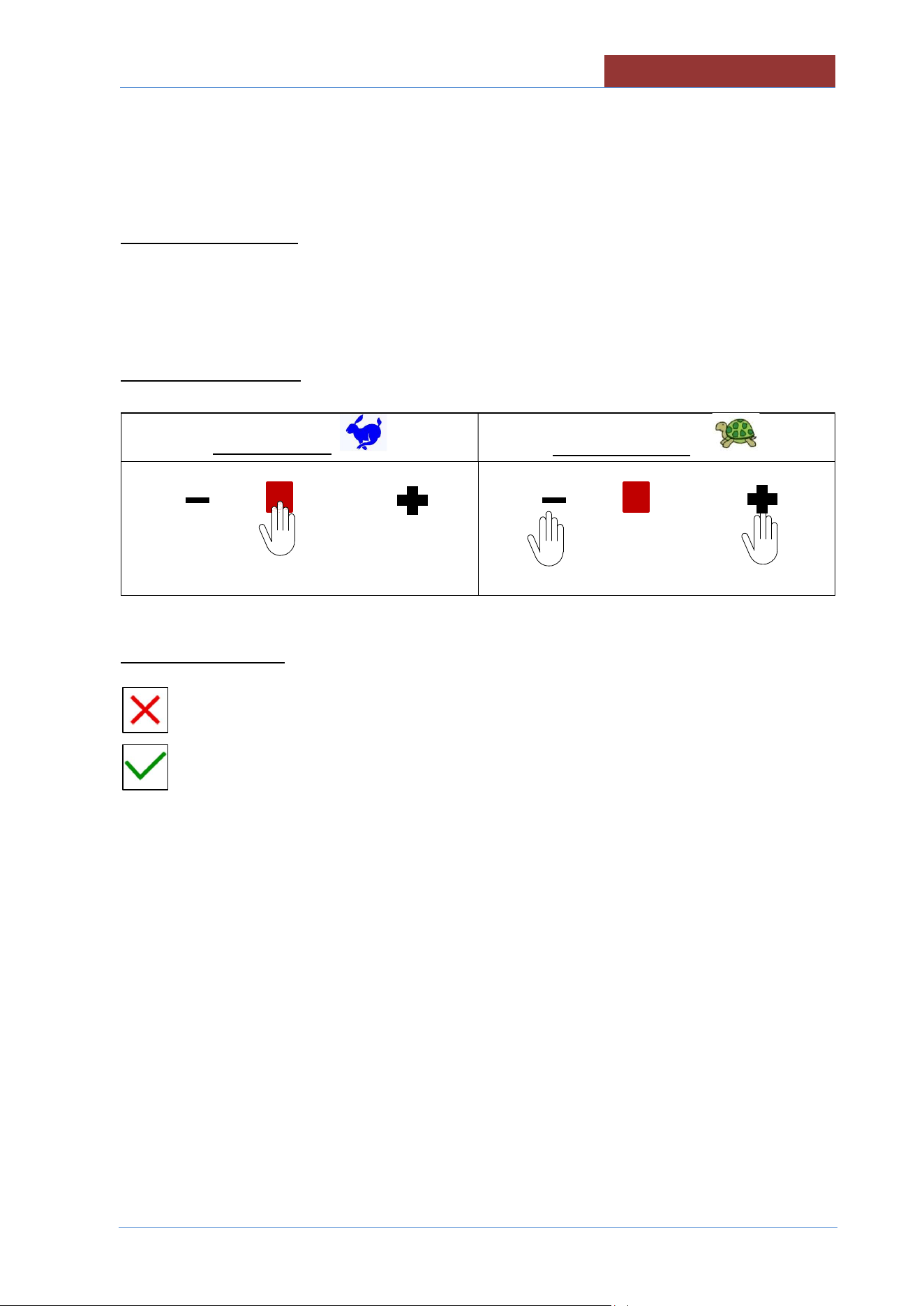
The following screen appears when setting any setpoint value:
left column: parameter of which you are changing the setpoint value.
right column: keypad + cursor for changing the setpoint.
100°C
20°C 120°C
min max
-------------------
1 2 3 4
5 6 7 8
- 9 0
Fields in the left column have the following meanings:
100°C
RED VALUE: VALUE OF WHICH YOUR ARE CHANGING THE SET
20°C
min
MINIMUM VALUE SETTABLE
120°C
max
MAXIMUM VALUE SETTABLE
x
SETTING SETPOINT PARAMETERS
05
-
UCPMDG
-
DIMU
-
00
-
EN
51
The values in the right column will be changed as follows:
SETTING WITH KEYPAD
TYPE THE DESIRED VALUE.
ATTENTION : THE VALUE MUST BE BETWEEN min AND max!
SETTING WITH CURSOR
QUICK SETTING
PRECISE SETTING
------------------
← →
------------------
EXIT FROM SETTINGS
Exit without confirming settings key
Exit confirming settings key
05
-
UCPMDG
-
DIMU
-
00
-
EN
COOKING PARAMETERS SETTING
52
18 COOKING PARAMETERS SETTING
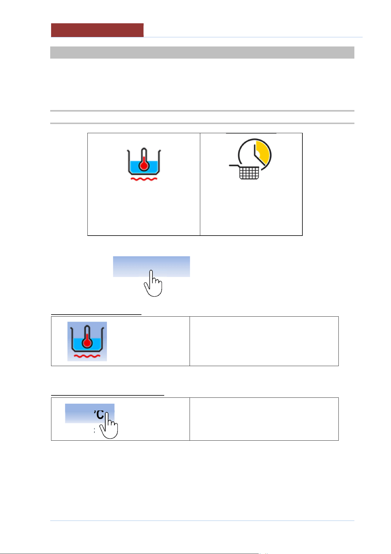
The setting of the following parameters can only be made from MAIN MENU :
1. PROGRAMS + MANUAL
2. SETTINGS + PROGRAMS
18.1 SETTING COOKING METHOD AND TEMPERATURE
100°C
20°C
00:06:00
--:--:--
AREA HIGHLIGHTED = SELECTION/SETTINGS
SETTING COOKING METHOD
SELECTING COOKING METHOD (see Cooking
methods in detail)
SETTING TEMPERATURE SETPOINT
20 °C
< COOKING SETPOINT (see SETPOINT)
< TEMPERATURE DISPLAY
SET THE SETPOINT AS DESCRIBED IN THE CHAPTER
10
0 °C
COOKING PARAMETERS SETTING
05
-
UCPMDG
-
DIMU
-
00
-
EN
53
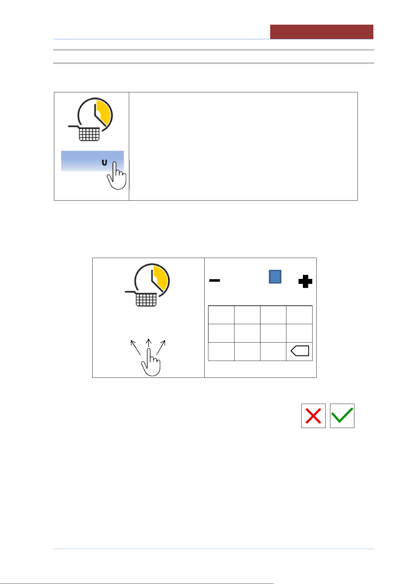
18.2 SETTING COOKING TIME
--:--:--
< COOKING TIME SETPOINT (see SETPOINT)
< COOKING TIME COUNTDOWN
00:06:00
---------------
1 2 3 4
5 6 7 8
- 9 0
HH:MM:SS
HH: 99 max; MM: 59 max; SS: 59 max
00:06:00
x
05
-
UCPMDG
-
DIMU
-
00
-
EN
CREATING PROGRAMS
54
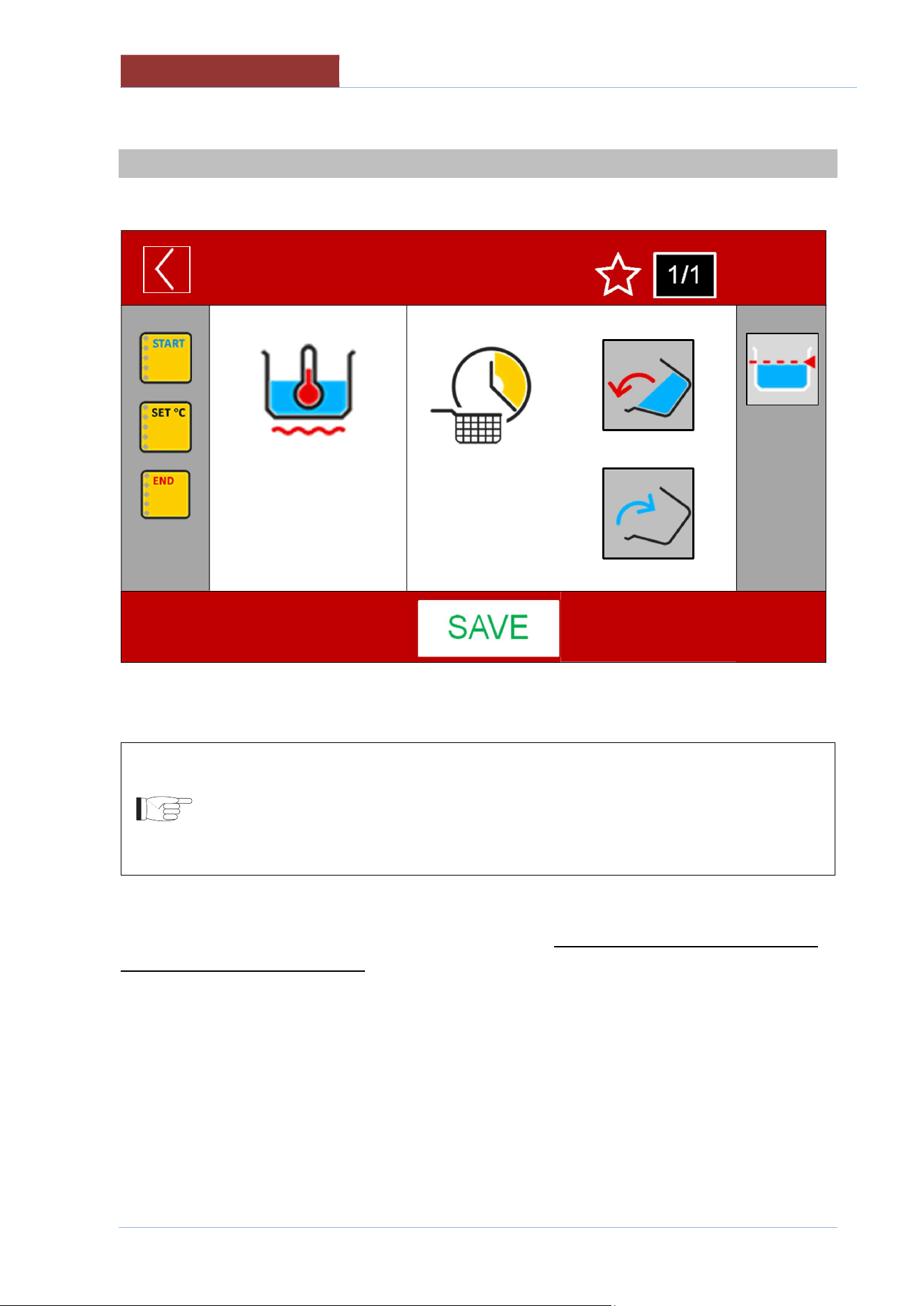
19 CREATING PROGRAMS
FROM MAIN MENU : SETTINGS> PROGRAMS> NEW
NEW PROGRAM
01:27: 35
17/12/ 2016
100°C
20°C
00:06:00
--:--:--
A PROGRAM CAN CONSIST OF 20 PHASES.
IN UCPM MODELS IT IS RECOMMENDED TO CREATE ONE-PHASE PROGRAMS.
IF A PROGRAM WITH SEVERAL PHASES IS CREATED, THE TRANSITION TO THE
NEXT PHASE CANNOT TAKE PLACE AUTOMATICALLY, THE COOKING TIME IS
THE DURATION OF THE IMMERSION TIME OF THE BASKET (REPEATABLE), NOT
THE HEATING DURATION TIME !!
THE PARAMETERS ARE CONSTANT WITHIN EACH PHASE. IF A SINGLE VALUE CHANGES, YOU
NEED TO CREATE A NEW PHASE!
THE CREATION OF THE PHASE CONSISTS OF ENTERING THE COOKING METHOD, COOKING
TIMES, AUTOMATIC FILLING THE PAN WITH H2O,FUNCTION STARCH SKIMMING .
IT IS ALSO POSSIBLE TO ENTER (IN EVERY PHASE) 2 MESSAGES PRESENT IN THE LEFT
COLUMN. (SEE MESSAGE SETTINGS)
CREATING PROGRAMS
05
-
UCPMDG
-
DIMU
-
00
-
EN
55
19.1 CREATING/DELETING PHASES
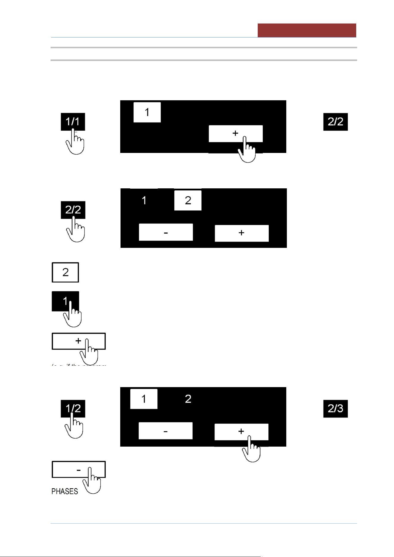
ONCE THE PARAMETERS OF PHASE 1 ARE SET, YOU CAN THEN ADD PHASE 2:
>
>
AFTER HAVING ADDED AND SET THE PARAMETERS OF PHASE 2, PRESSING ON THE
PHASE/PHASE FIELD DISPLAYS THE FOLLOWING SCREEN:
>
SHOWS THE CURRENT PHASE
RETURNS TO PHASE 1 SETTINGS
ENTERS A NEW PHASE AFTER THE HIGHLIGHTED PHASE
(e.g. if the program consists of 2 phases and I want to insert a phase between 1 and 2, I have to select
phase 1 and press the + key, phase 2 becomes 3 and you need to set the parameters for phase 2).
>
>
DELETES THE HIGHLIGHTED PHASE AND RENUMBERS THE FOLLOWING
PHASES
(e.g. if the program consists of 3 phases and phase 2 is deleted, phase 3 becomes 2)
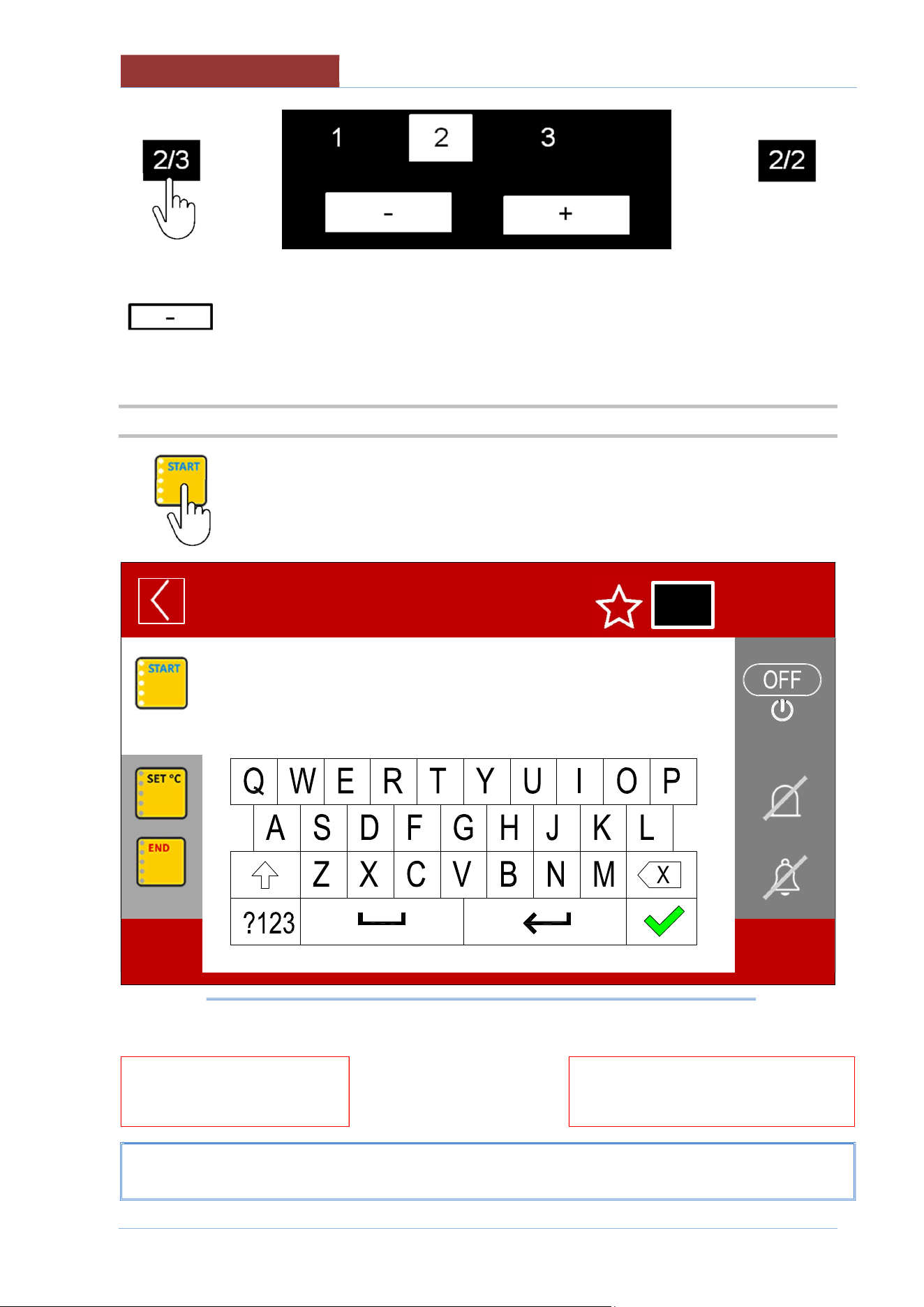
05
-
UCPMDG
-
DIMU
-
00
-
EN
CR
EATING PROGRAMS
56
>
>
ATTENTION: NO CONFIRMATION IS REQUIRED WHEN DELETING PHASES! PRESSING THE KEY
IMMEDIATELY DELETES THE CURRENT PHASE!
PHASE 1 CAN NOT BE DELETED!
19.2 MESSAGE SETTINGS
The following screen appears when selecting the message icon:
NEW PROGRAM
01:27:35
17/12/2016
______
↑
_______
↑
MESSAGE SELECTION KEYS
↑
MESSAGE SETTINGS KEYS
MESSAGE WRITING AREA
1/1
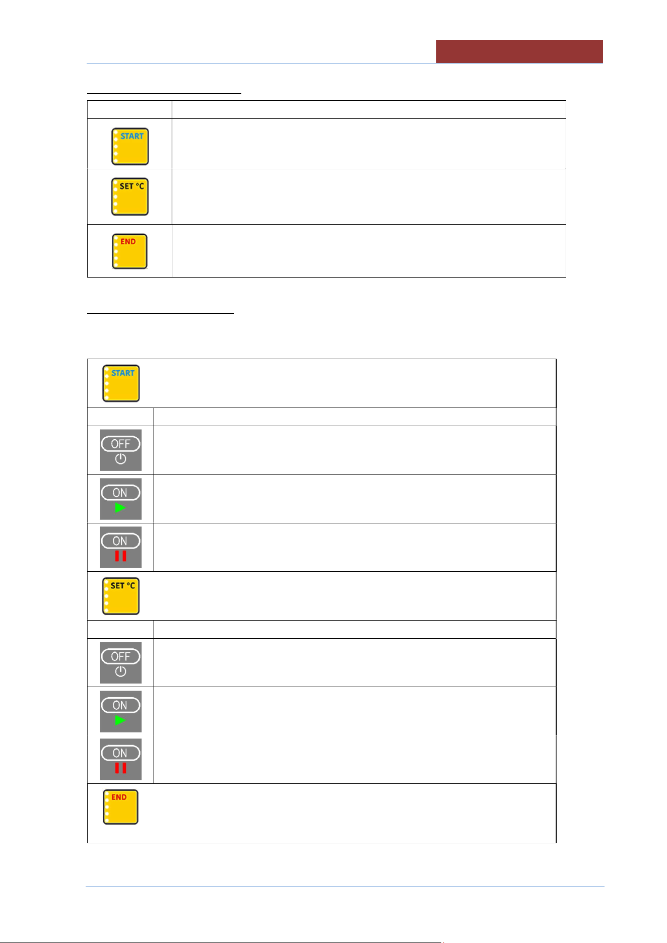
CREATING PROGRAMS
05
-
UCPMDG
-
DIMU
-
00
-
EN
57
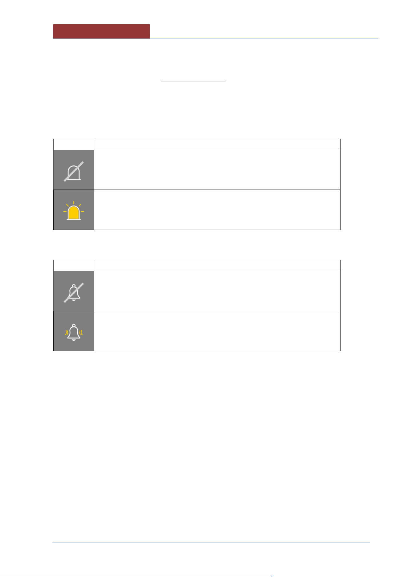
MESSAGE SELECTION KEYS
Icon
Description
MESSAGE AT THE BEGINNING OF THE PHASE
MESSAGE ON REACHING SETPOINT
MESSAGE AT THE END OF THE PHASE . Not working (for UCPM..)
MESSAGE SETTINGS KEYS
THE KEY ON THE TOP RIGHT TAKES ON THE FOLLOWING FUNCTIONS SPECIFIED IN RELATION
TO THE SELECTED MESSAGE (START; SET °C: END)
START MESSAGE
Key
Behaviour when program running
No message appears
The message appears
The heating starts at "ON"
The message appears
The heating stays "OFF" until you reply to the message
MESSAGE ON REACHING SETPOINT
Key
Behaviour when program running
No message appears
The message appears
Heating keeps the SETPOINT
END OF PHASE MESSAGE
Not working (for UCPM..)
05
-
UCPMDG
-
DIMU
-
00
-
EN
CREATING PROGRAMS
58
ATTENTION : IF THE MESSAGE IS SET TO OFF, ALL THE SETTINGS DESCRIBED BELOW
(FLASHING, BUZZER, AND TEXT) WILL NOT APPEAR WHEN THE PROGRAM IS RUNNING!
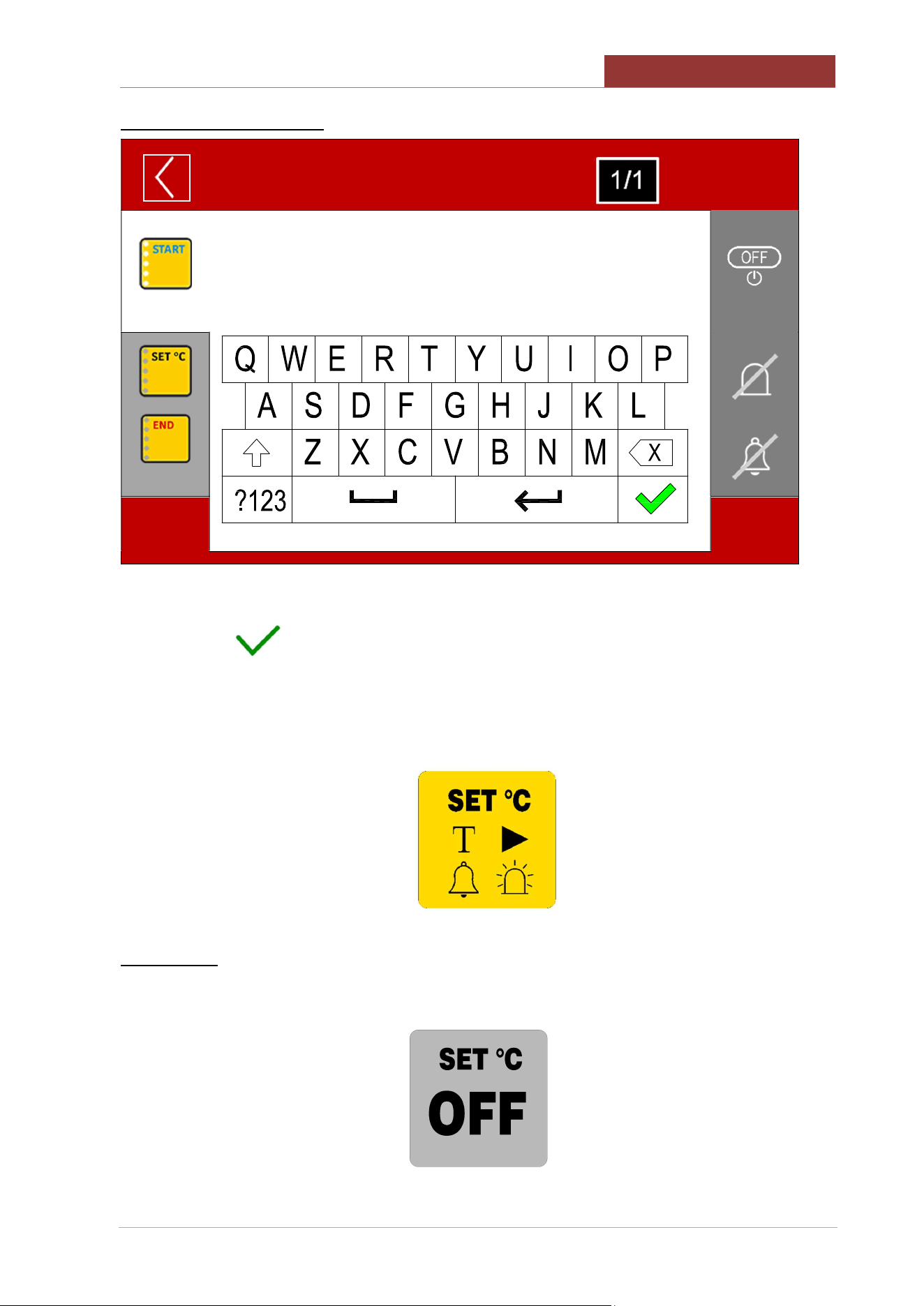
THE FOLLOWING KEYS HAVE THE SAME FUNCTIONS FOR ALL MESSAGES (START; SET °C;
END)
Flashing (optional)
Right key
Be
haviour when program running
Flashing not enabled
When the message appears, the flashing light also switches on.
(message frame flashing or external flashing optional)
Buzzer
Right key
Behaviour when program running
Buzzer not enabled
When the message appears, the buzzer sounds
CREATING PROGRAMS
05
-
UCPMDG
-
DIMU
-
00
-
EN
59
ENTERING MESSAGE TEXT
NEW PROGRAM
01:27: 35
17/12/ 2016
USE THE KEYPAD TO ENTER A DESCRIPTIVE TEXT (MAX 200 CHARACTERS) AND CONFIRM
WITH THE KEY .
AFTER HAVING SET ALL THE VARIABLES WITHIN THE MESSAGE, THE RELATED MESSAGE
ICON WILL SHOW WITHIN ALL THE SYMBOLS THAT SUMMARISE THE SETTINGS OF THE
MESSAGE ITSELF.
TEXT PRESENT>
BUZZER ENABLED>
< ACTION TYPE
< FLASHING ENABLED
ATTENTION: IF THE MESSAGE IS IN "OFF", IT APPEARS ON A GREY BACKGROUND.
ANY SETTINGS (TEXT, BUZZER, FLASHING) WILL NOT BE CANCELLED FROM MESSAGE
SETTING!
05
-
UCPMDG
-
DIMU
-
00
-
EN
CREATING PROGRAMS
60
19.3 SAVING A PROGRAM
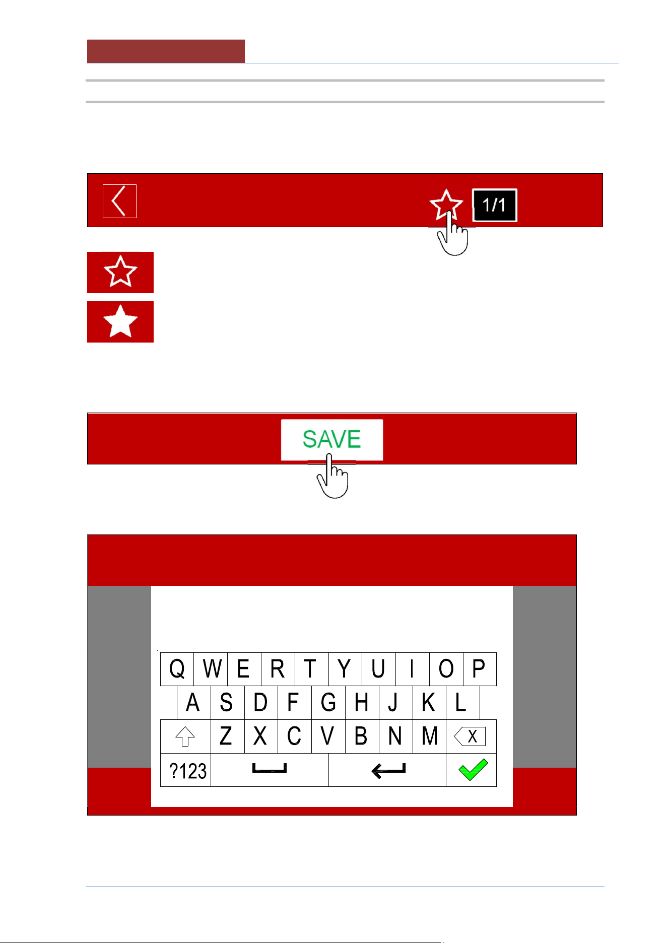
IF YOU WANT TO ADD THE PROGRAM TO THE LIST OF FAVOURITES, PRESS THE "STAR"
SYMBOL.
NEW PROGRAM
01:27: 35
17/12/ 2016
Program NOT added to favourites
Program added to favourites
PRESS THE "SAVE" BUTTON
THE KEYPAD APPEARS TO ENTER THE PROGRAM NAME.
PROGRAM NAME
01:27: 35
17/12/ 2016
CREATING PROGRAMS
05
-
UCPMDG
-
DIMU
-
00
-
EN
61
ENTER THE PROGRAM NAME AND CONFIRM WITH THE KEY .
ATTENTION : THE PROGRAM DOES NOT PERFORM A CHECK TO SEE IF A PROGRAM WITH THE
SAME NAME ALREADY EXISTS. 2 PROGRAMS WILL BE SAVED WITH THE SAME NAME, WITH HE
POSSIBILITY OF RENAMING THEM. (SEE EDITING PROGRAMS)
THE SCREEN APPEARS FOR LINKING THE PROGRAM TO A CATEGORY
19.4 EDIT/ COPY/ RENAME PROGRAM
FROM SETTINGS> PROGRAMS
SELECT THE CATEGORY OF THE PROGRAM OR ALL
SELECT THE PROGRAM THAT YOU WANT TO EDIT.
REFER TO "CREATING MULTIPHASE PROGRAMS" FOR EDITING
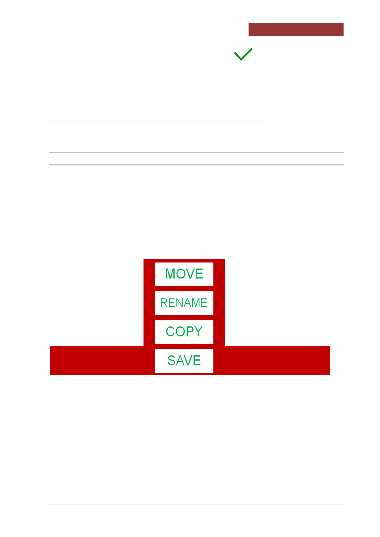
ONCE CHANGES HAVE BEEN MADE, PRESS THE SAVE KEY AND THE FOLLOWING SCREEN
APPEARS:
SAVE: SAVES THE PROGRAM (NO FURTHER REQUEST)
COPY: A NEW PROGRAM IS CREATED (GIVE THE NAME TO THE PROGRAM AND THE
CATEGORY)
RENAME: GIVES A NEW NAME TO THE PROGRAM (SAVING THE CHANGES MADE)
MOVE: MOVES THE PROGRAM TO ANOTHER GROUP (PRESS THE SAVE KEY TO CONFIRM)
05
-
UCPMDG
-
DIMU
-
00
-
EN
CREATING PROGRAMS
62
19.5 DELETING A PROGRAM
FROM SETTINGS> PROGRAMS
SELECT THE CATEGORY OF THE PROGRAM OR ALL
SELECT THE PROGRAM YOU WANT TO DELETE BY PRESSING ON THE NAME OF THE
PROGRAM FOR ABOUT 2 SEC.
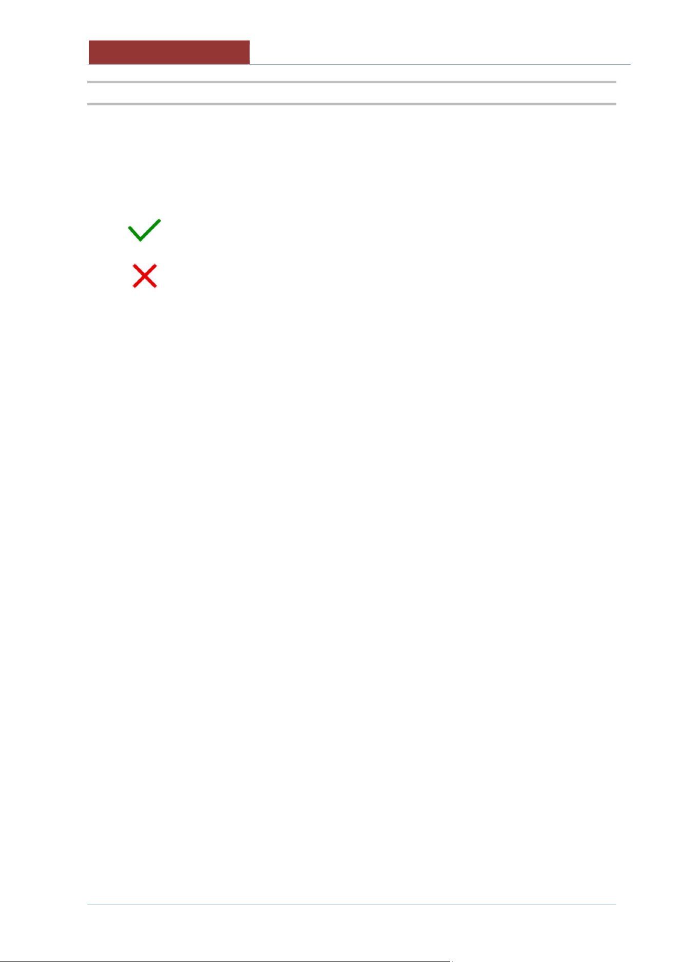
A POP-UP WILL BE APPEAR TO CONFIRM PROGRAM DELETION
CONFIRM DELETION
CANCEL DELETION
RUNNING
A COOKING WITH BASKET
05
-
UCPMDG
-
DIMU
-
00
-
EN
63
20 RUNNING A COOKING WITH BASKET
Before starting any cooking make sure that:
The tipping arm is correctly assembled in the seats and with the seat for the
basket pin upwards.
The basket is correctly assembled. (basket locked with levers)
The drain valve is closed.
The automatic loading of the water in the tank is activated
Select Manual cooking (20.1) or select a existing Program (20.2)
20.1 SELECT A PROGRAM/MANUAL COOKING
FROM MAIN MENU : PROGRAMS> MANUAL
SET ALL THE COOKING PARAMETERS (COOKING METOD; COOHING TIME)
20.2 SELECT AN EXISTING PROGRAM
FROM MAIN MENU : PROGRAMS> SELECT THE PROGRAM THAT YOU WANT TO RUN FROM THE
FOLDER: ALL; CATEGORY (MEAT, SAUCES, ETC) OR FAVOURITES
PRESS THE START KEY
NOTE 1)
WHEN RUNNING THE PROGRAM YOU CAN CHANGE THE TEMPERATURE AND TIME SETPOINT
(ONLY IN THE PHASE IN WHICH THE PROGRAM IS CURRENTLY RUNNING) BY PRESSING IN THE
FIELD CORRESPONDING TO THE SET VALUES FOR ABOUT 2 sec. .
IT IS NOT POSSIBLE TO CHANGE THE COOKING METHOD AND TIME!!
NOTE 2)
IF A PROGRAM WITH SEVERAL PHASES HAS BEEN SELECTED (NOT RECOMMENDED), THE
PASSAGE TO THE NEXT PHASE CAN BE PERFORMED MANUALLY.
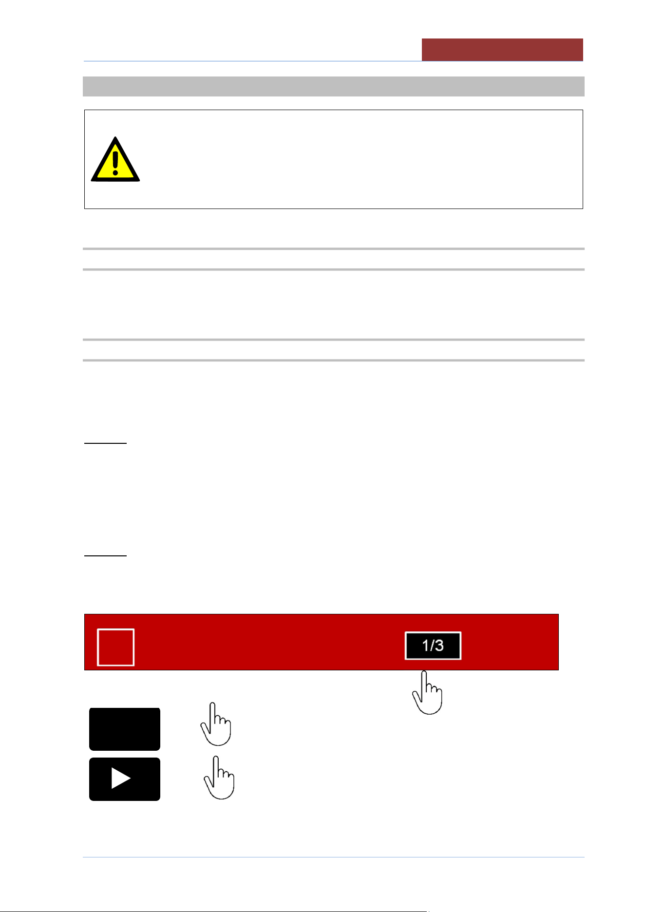
YOU CAN MOVE ON TO THE NEXT PHASE BY PRESSING THE "PROGRAM PHASE" FIELD.
XXX1234
01:27: 35
17/12/ 2016
APPEARS:
x1
IT RETURNS TO THE PHASE IN PROGRESS
x2
IT PASSES TO THE NEXT PHASE.
ATTENTION: IF IT IS THE LAST PHASE, THE PROGRAM
FINISHES!
1/3
I
05
-
UCPMDG
-
DIMU
-
00
-
EN
RUNNING A COOKING WITH BASKET
64
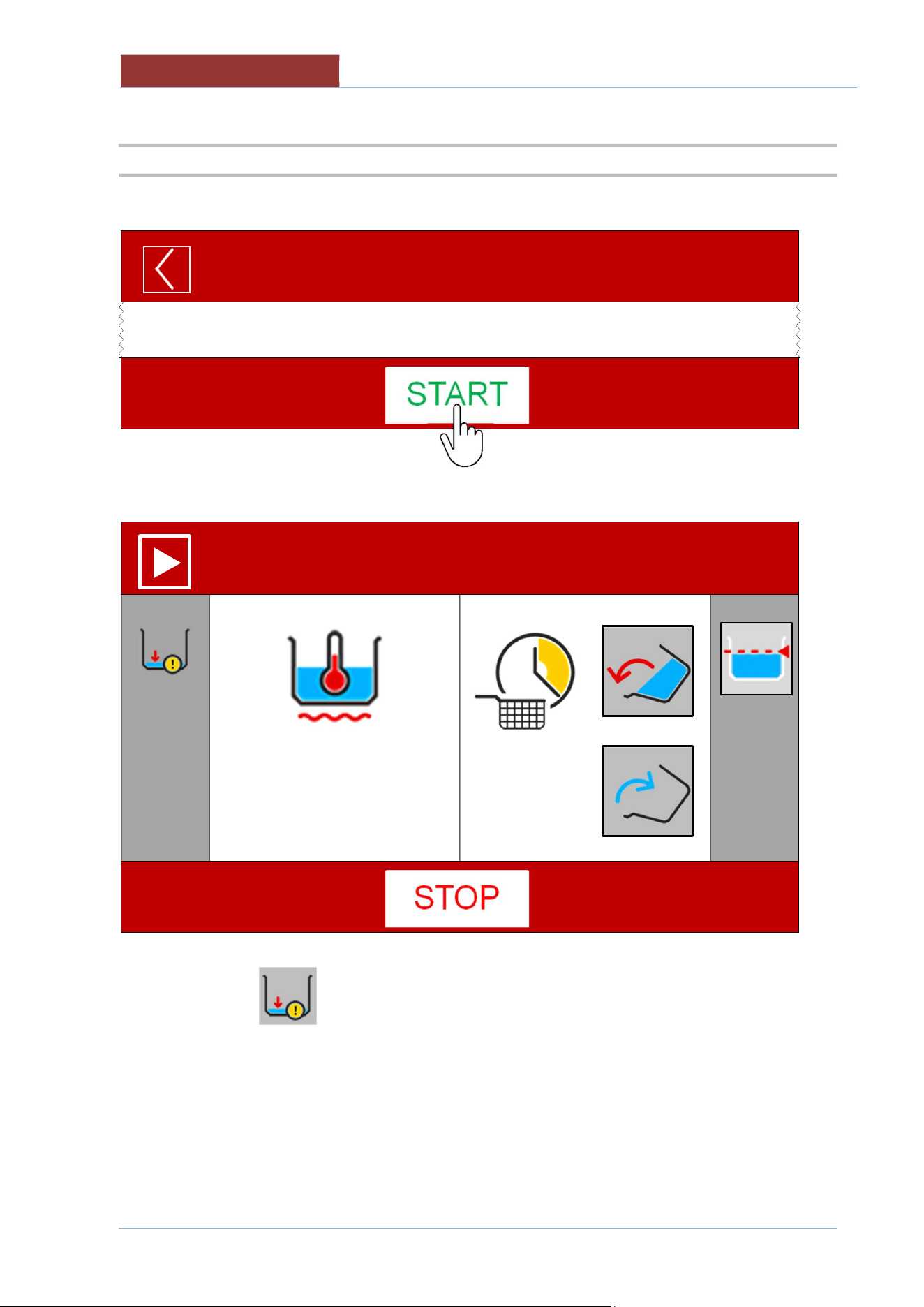
20.3 STARTING HEATING
PRESS THE START KEY
MANUAL
01:27: 35
17/12/ 2016
THE SCREEN BECOMES
XXX1234
01:27: 35
17/12/ 2016
100°C
20°C
00:06:00
--:--:--
Attention: if the icon appears on the left column, the heating does not start because the minimum
level of water in the tank has not been reached.
When the level is reached, the icon disappears and heating starts.
RUNNING A COOKING WITH BASKET
05
-
UCPMDG
-
DIMU
-
00
-
EN
65
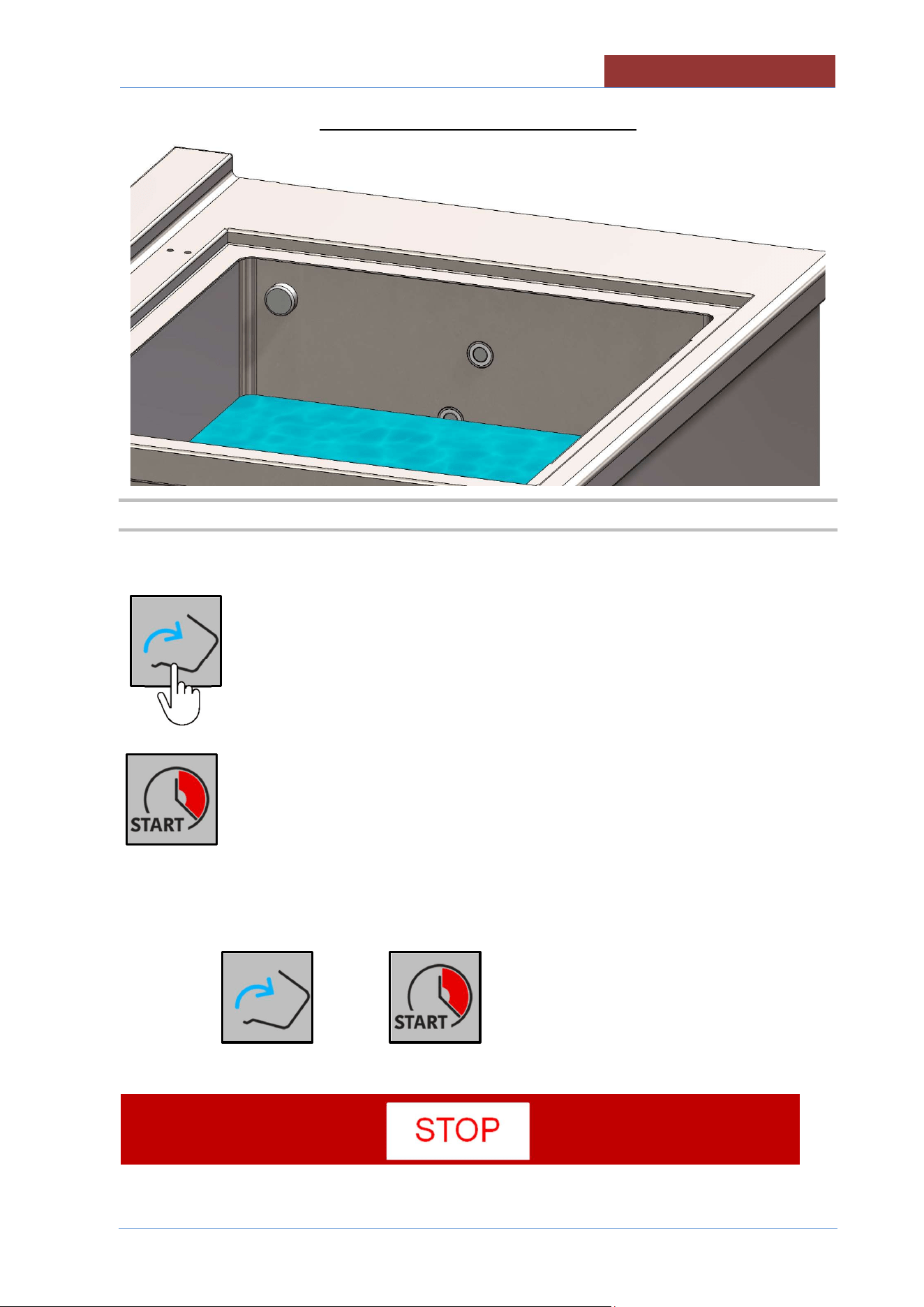
MINIMUM LEVEL OF WATER FOR HEATING
20.4 IMMERSING THE BASKET
Press the button
When the basket reaches the cooking position, the button changes to
ATTENTION:
1.The bottom becomes only if heating has been started !!
The key on the function bar must be "STOP".
05
-
UCPMDG
-
DIMU
-
00
-
EN
RUNNING A COOKING WITH BASKET
66
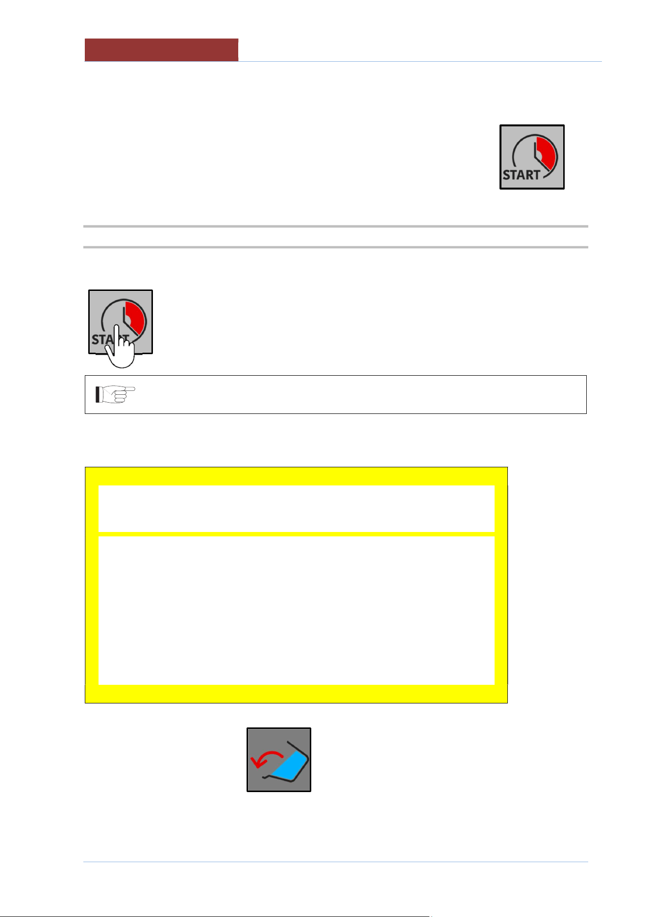
2.If the basket is already in the cooking position, the button appears immediately ,
20.5 COOKING TIME (BASKET IMMERSION)
Once the baskets have reached the cooking position, pressing the button starts the countdown of the
basket dive time.
If the time is set to 00:00:00 by pressing the button, the basket immediately
overturns to the dripping position.
Before the cooking time runs out (about 10 sec.), a message appears with the countdown for basket
tilting (with buzzer).
Warning
Lift Up tilting baskets in:
10 sec
At the end of the time the bottom appears (in dark grey) until the basket are automatically
tilted to the intermediate position (dripping position).
RUNNING A COOKING WITH BASKET
05
-
UCPMDG
-
DIMU
-
00
-
EN
67
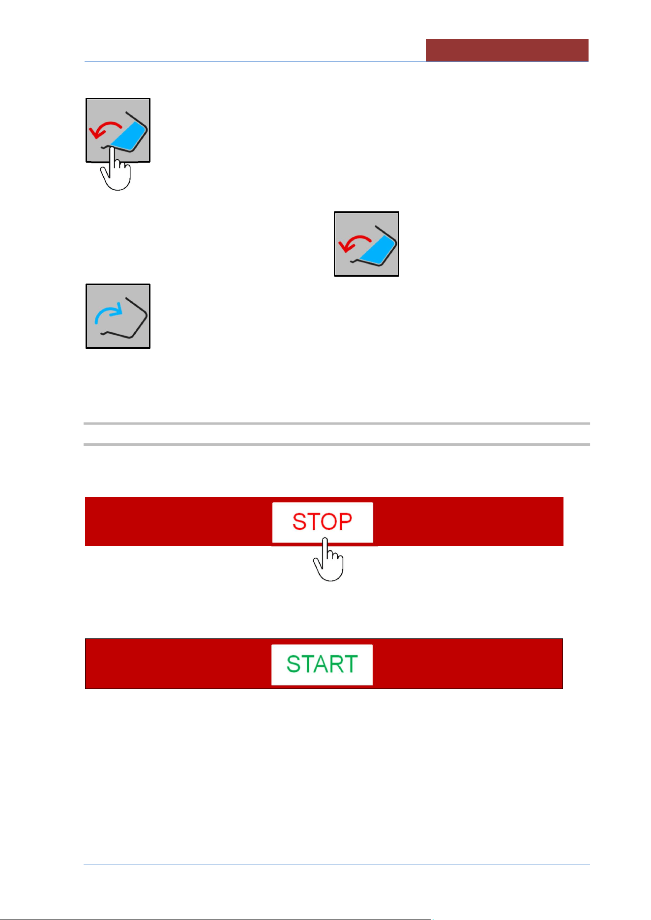
To completely download the product, press and hold the button
HOLD
With the basket completely upside down, the button disappears and only the button
remains .
If you want to run a new cycle, load the new product and repeat the cooking cycle as described above.
20.6 END OF COOKING/HEATING
At the end of the cooking cycles, switch off the heating by pressing the STOP button.
The botton becomes “START”
05
-
UCPMDG
-
DIMU
-
00
-
EN
COOKING WITH DELAY TIMER
68
21 COOKING WITH DELAY TIMER
After having chosen the program to run,
press the button to access the settings for cooking with delay timer.
It is possible to set the delayed start in two ways:
Top row:
setting the start date and time: set the hour and minutes, and, if necessary, the day (with a maximum of 7
days in advance).
Bottom row:
setting delayed start: starting from the current time and date, set the hour and minutes, and if applicable
the day(s) delayed (with a maximum of 7 days in advance).
In automatic, when setting in one mode or the other, the other row will also be updated. (if the start time
and date are set, the delayed time will be updated, and vice versa).
To exit without saving, press the key .
Press the START key to confirm.
The display shows the time and date when it will start, and the bottom row shows the time remaining until
it starts.
To cancel the delayed start, press the STOP button.
This function is recommended when you want to arrive in the kitchen with the cooking
water already at temperature.
However, it is necessary either to fill the tank before starting the deferred cooking (not
recommended), or it is preferable to activate the button if manual cooking, or
choose a program with the button active.
The tank will fill simultaneously with the departure of the deferred cooking.
Make sure that the drain valve is closed.
FILLING PAN WITH H2O
05
-
UCPMDG
-
DIMU
-
00
-
EN
69
22 FILLING PAN WITH H2O
22.1 AUTOMATIC FILLING THE PAN WITH H2O
To activate the automatic loading of the water in the tank, press the button (present in the right column)
OFF automatic loading H2O in tank and automatic level control.
the button becomes
ON automatic loading H2O in tank and automatic level control
Water will be loaded into the tank up to the upper probe and kept at this level.
To deactivate the load and the level control, press the button again.
05
-
UCPMDG
-
DIMU
-
00
-
EN
FILLING PAN WITH H2O
70
22.2 FUNCTION STARCH SKIMMING
During cooking, impurity’s may form on the surface of the water. This function allows for a constant
flow of clean water into the cavity forcing impure water to-be removed through overflow of the tank
To activate the function starch skimming, press the button (present in the right column)
OFF starch skimming
the button becomes
ON starch skimming
To deactivate the function, press the button again.
CLEANING SHOWER OPERATION (OPTIONAL)
05
-
UCPMDG
-
DIMU
-
00
-
EN
71
23 CLEANING SHOWER OPERATION (OPTIONAL)
To activate the shower , press the button (present in the right column)
OFF cleaning shower
the button becomes
ON cleaning shower
To deactivate the function, press the button again.
To avoid that the system is always under pressure, the activation of the shower is
timed.
When the time expires, the key returns automatically .
To change the activation time, press the button for 2 seconds
2 sec.
Press on the indicated value,
10 min
Change the value (range 1-999 minutes) and confirm with the bottom
05
-
UCPMDG
-
DIMU
-
00
-
EN
MOVING THE BASKET
72
24 MOVING THE BASKET
To move the basket, keep pressed the corresponding key on the display or external keypad.
The keys on the display are disabled when the basket tilting limits are reached.
With a completely horizontal basket = enabled only
With a tilted basket = enabled only
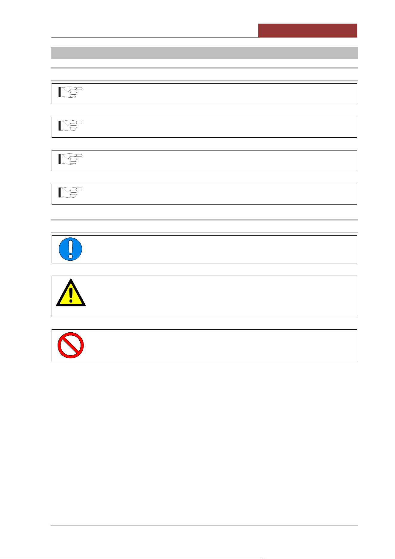
25 TANK DRAIN
01
Drain valve
02
Drain valve lever
To drain the pan, turn the lever to the ON position.
To avoid unnecessary waste of water, make sure that the automatic load and the
function starch skimming are deactivated.
The buttons must be :
02
01
CLEANING AND CARE
05
-
UCPMDG
-
DIMU
-
00
-
EN
73
26 CLEANING AND CARE
26.1 GENERAL INFORMATION
Do not use aggressive substances or abrasive detergents when cleaning stainless steel
parts.
Avoid using iron scourers on steel parts as rust formation may occur. For the same
reason avoid contact with ferrous materials.
No sandpaper or abrasive paper should be used during cleaning. In special cases,
pumice stone may be used in powder form.
In the event of particularly resistant dirt, we recommend the use of abrasive sponges
(e.g. Scotch-Brite).
26.2 DAILY CLEANING
Always wear protective clothing required by current regulations.
For safety reasons, clean the machine when it is cold and off (with the emergency button
pressed) (or on stand-by if cooking with delay timer).
When cleaning the appliance never spray water directly in order not to cause
infiltration and damage to the parts.
Never use water jets in the flue in gas versions.
Clean the pan with water and detergent, rinse well and dry thoroughly with a soft cloth
Clean the outside with a sponge soaked in hot water and a suitable detergent readily available on the
market.
Always rinse well and dry with a soft cloth.
05
-
UCPMDG
-
DIMU
-
00
-
EN
CLEANING AND CARE
74
26.3 TANK AND BASKET CLEANING
Clean the tank with water and a detergent, rinse thoroughly and dry well with a soft cloth.
Rinse always thoroughly and dry with a soft cloth.
To access the inside of the tank the following procedure:
Remove the basket (see.FIG.”BASKET”)
1. Lift the basket up to the limit switches.
2. Unlock your basket with the appropriate levers
3. Remove the basket from the lift arm .
WARNING: OPERATION TO BE PERFORMED IN TWO PEOPLE.
Remove the tilting arm (see.FIG.”TILTING ARM”)
4. After removing the basket you can remove the tilting arm from tipping by lifting
it from the side where there is the steel support (detail “a-1”).
5. Remove the arm from the crankshaft side (detail “b-2”).
Perform a careful cleaning of the tank, especially in the level and
temperature probes area.
Remove limestone from the bottom of the tank to avoid bad heat
transmission.
Attention, when you finish cleaning:
WARNING: IF YOU ARE MORE 'MACHINES IN THE LOCAL NOT CHANGE THE TILTING ARMS AND
BASKETS!
1. Reassemble the tilting arm with the seats for the basket pin facing upwards.
(see.FIG.TILTING ARM ). Fit first on the crankshaft side (detail “b.3”), and then rest
the arm pin in its seat (detail “a.4”)
2. Reassemble the basket making sure that the basket pin is in its seat
(see.FIG.BASKET)
3. Lock the basket with the appropriate levers (see.FIG.BASKET)
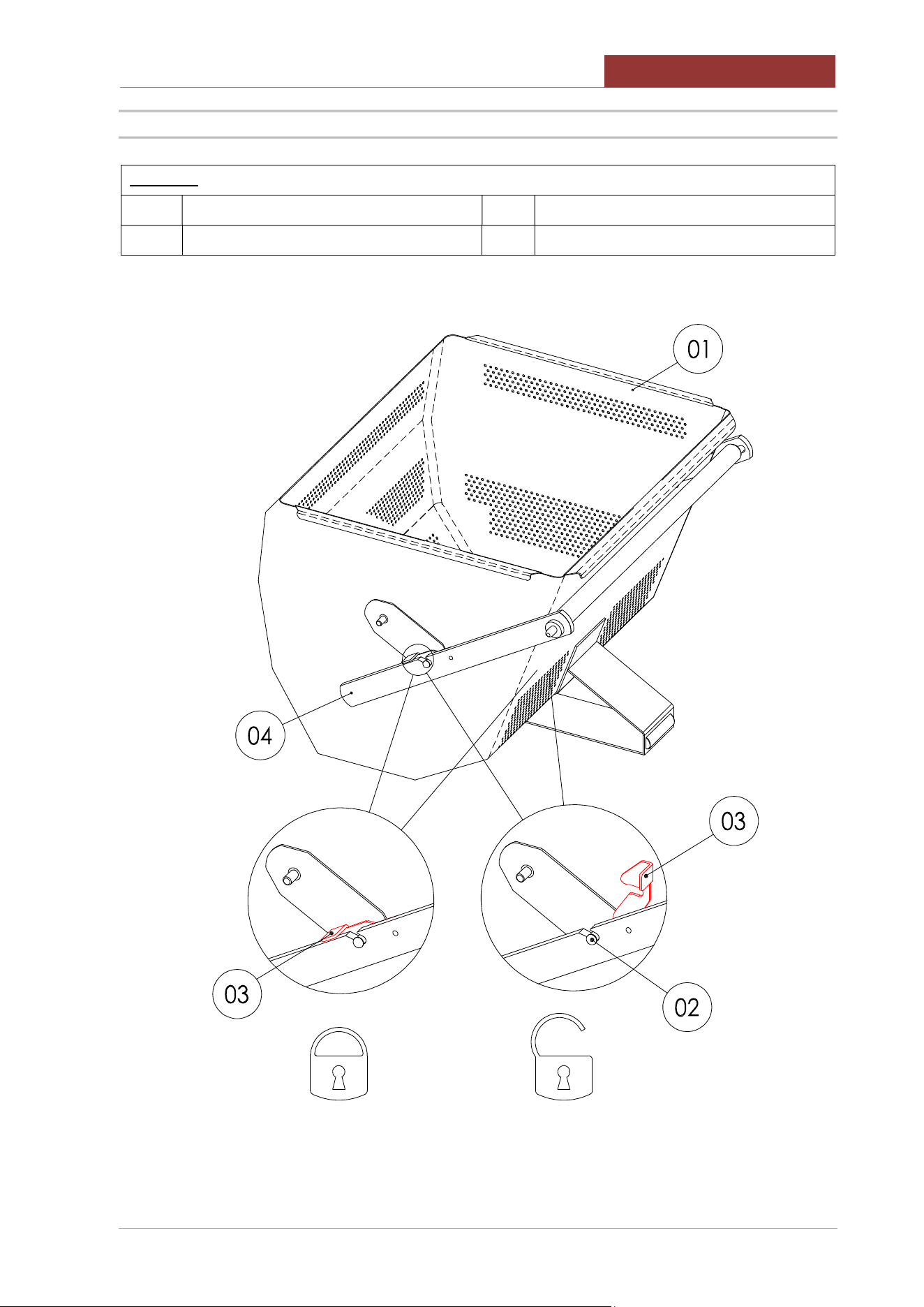
CLEANING AND CARE
05
-
UCPMDG
-
DIMU
-
00
-
EN
75
26.3.1 BASKET
LEGEND:
01
Basket
03
Locking lever
02
Basket pin
04
Tilting arm
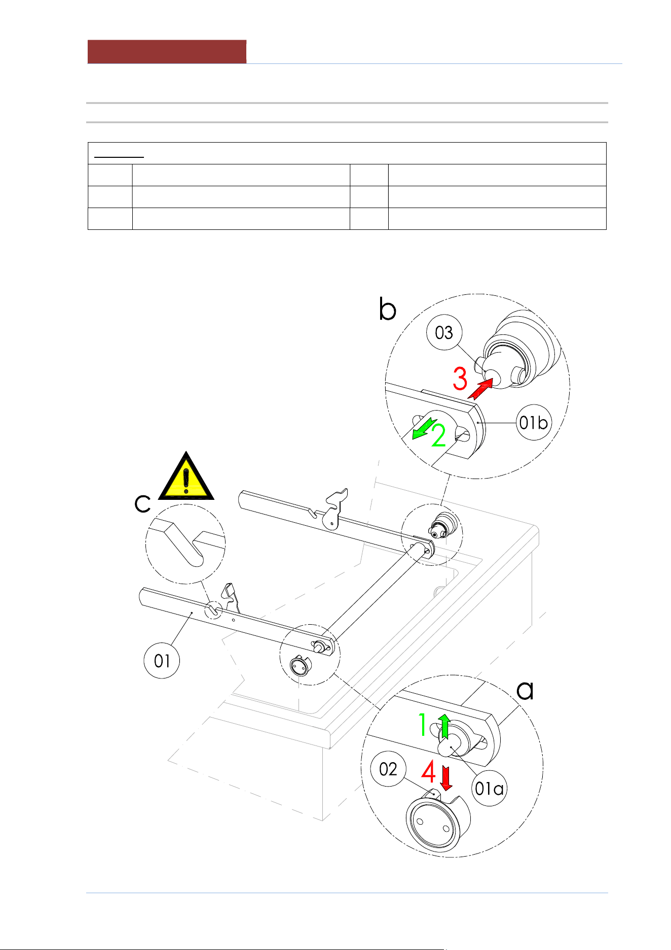
05
-
UCPMDG
-
DIMU
-
00
-
EN
CLEANING AND CARE
76
26.3.2 TILTING ARM
LEGEND:
01 Tilting arm 03 Steel support
01a Tilting arm (steel support side) 04 Crankshaft
01b
Tilting arm (crankshaft side)
To remove the tilting arm : 1 - 2
To reassemble the tilting arm : 3 - 4
CLEANING AND CARE
05
-
UCPMDG
-
DIMU
-
00
-
EN
77
26.4 PRECAUTIONS IN CASE OF PROLONGED INACTIVITY
If the appliance has been inactive for a prolonged period of time (holidays, seasonal work...), clean well,
remove any residue and ensure it is dry.
Leave the lid open so that air can circulate inside the pan.
The room must be sufficiently ventilated.
Disconnect all water, electricity and gas supplies.
26.5 PRECAUTIONS IN CASE OF MALFUNCTION
Should malfunctions occur during use, switch off the appliance immediately and disconnect or stop all
supplies (gas and water).
Request assistance from technical support or a qualified technician.
The manufacturer assumes no responsibility or warranty commitment for injuries
and damage due to non-compliance with the instructions or any installation or
maintenance that does not comply with safety standards.
The same applies in case of improper use of the appliance by the operator.
05
-
UCPMDG
-
DIMU
-
00
-
EN
MAINTENANCE
78
27 MAINTENANCE
27.1 MAINTENANCE OF THE APPLIANCE
All maintenance work must only be performed by a specialist technical service
centre!
In order to keep the appliance working efficiently, it is advisable to perform annual maintenance, which
includes checking the status of components subject to wear and tear (pipes, etc.).
It is advisable to replace any worn components during maintenance, in order to avoid further call outs and
unexpected issues and faults with the appliance.
Therefore, it is recommended to sign a maintenance contract with a reliable technical support centre.
27.2 PERIODIC MAINTENANCE
Periodic inspections will minimise machine downtime and increase operating efficiency.
The following points must be checked:
Periodic inspections will minimise machine downtime and increase operating efficiency.
The following points must be checked:
BY OPERATOR
DAILY CHECKS
1. Thoroughly clean the machine daily
QUARTERLY CHECKS
2. Check the following are undamaged and intact:
Screen controls, switches, warning lights.
Emergency button:
Contact technical support if they are damaged.

MAINTENANCE
05
-
UCPMDG
-
DIMU
-
00
-
EN
79
BY SERVICE TECHNICIAN
For each operation:
Carefully close all the panels. .
The inside of the appliance should be kept clean.
Electrical wiring should be kept securely connected and in good condition.
ANNUAL CHECKS / ACTION
1. Check coupling panels, must be perfectly closed with all the screws.
2. Check the sealing water system (load tap water).
3. Check that terminals connections of electrical parts are well fastened. Clean electrical parts .
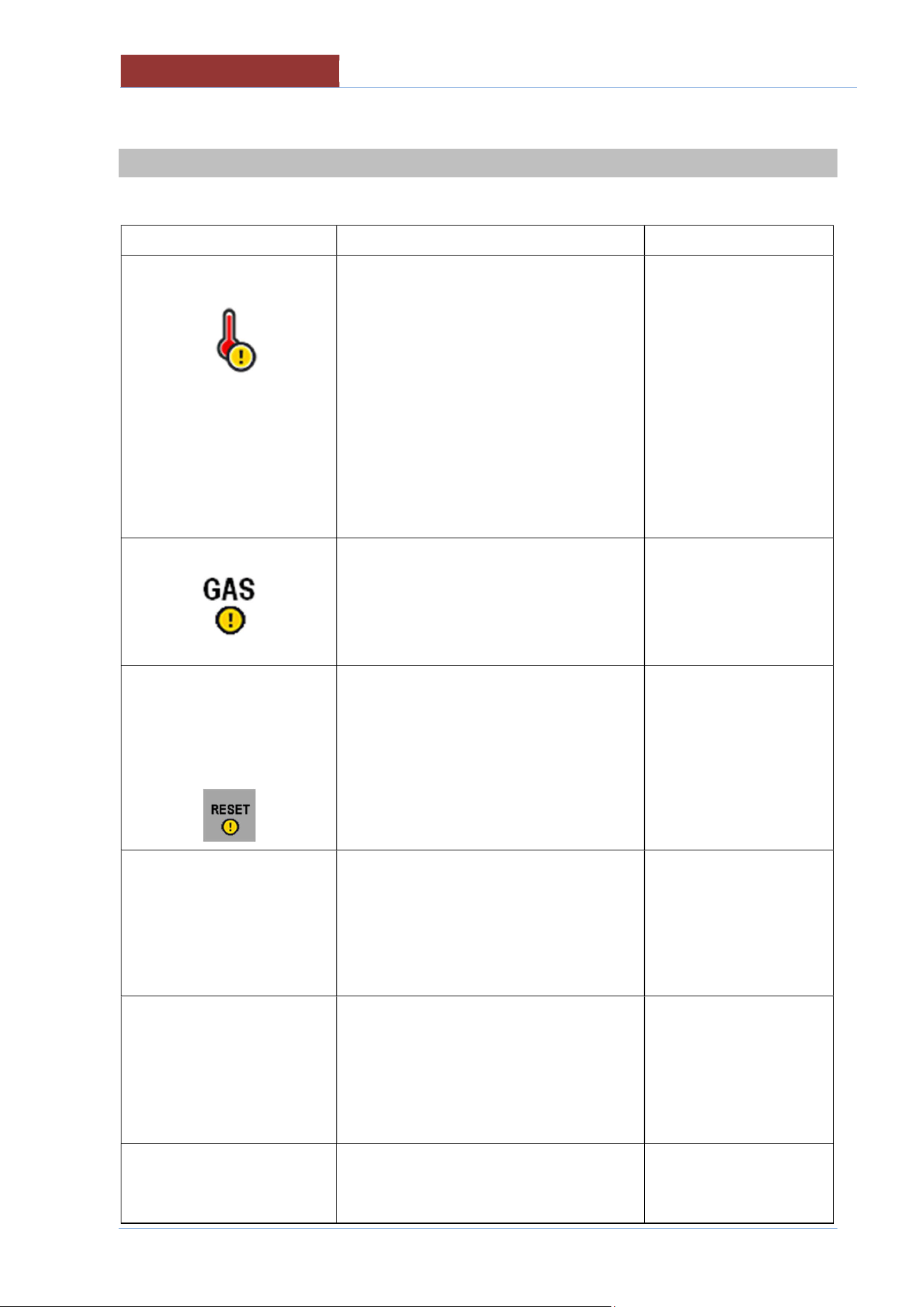
05
-
UCPMDG
-
DIMU
-
00
-
EN
DISPLAY MESSAGES
80
28 DISPLAY MESSAGES
Message Meaning Solution
Safety thermostat has been triggered.
Overtemperature on the heating elements
(only electric model UCPMDE)
Possible presence of limestone on the
bottom of the tank.
Turn off the machine
using the emergency
button and allow the
machine to cool down.
With the machine cold,
carefully clean the
bottom of the tank from
limestone.
If the thermostat is
triggered again, contact
the support centre.
Insufficient gas pressure.
It is not possible to start cooking.
Verify that gas is
supplied and that the
pressure is sufficient.
Contact the support
centre.
!! BLOCK GAS
DEVICE !!
PRESS
**RESET**
If a cooking phase has started and
insufficient gas pressure has been
detected on 4 consecutive occasions or
there is a fault on the flame detection
system, the central unit will be interrupted.
Press
“RESET”.
After 3 RESET attempts,
the message below
appears.
!! GAS SYSTEM
ANOMALY!!
CONTACT TECHNICAL
ASSISTANCE
Problem with the gas system: gas central
unit fuses, gas solenoid valve, spark plugs
and pilot light plug.
Contact technical support.
PROBES ERROR
One or more of the
appliance's
sensors/probes are faulty (or not
connected). Cooking methods that use
these sensors/probes will be disabled (light
grey) until they are repaired.
Contact technical support.
INTERNAL ERROR
Connection error between the relay board
and keypad board
Switch the appliance off,
and switch back on after
two minutes, if the
DISPLAY M
ESSAGES
05
-
UCPMDG
-
DIMU
-
00
-
EN
81
System board error.
problem persists, call a
technician
BLACK OUT ERROR
t.b.d
INVERTER ERROR
Connection error
between relay board and
inverter
Contact technical support.
EXTERNAL MEMORY
ERROR
SD memory card not available.
Contact technical support.
OUTPUT
CONFIGURATION
ERROR
PROGRAMMING ERROR. Dual output
assignment!!
Contact technical support.