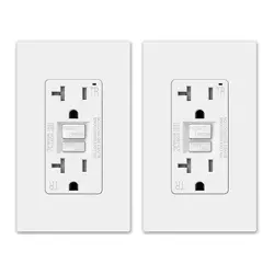
A: One cable (2 or 3 wires) entering the box
B: Two cables (4 or 6 wires) entering the box
Rev.1
Front
Back
Installing and
Testing a GFCI
Receptacle
Please read this leaflet
completely before
getting started.
• To prevent severe shock or electrocution
always turn the power OFF at the service
panel before working with wiring.
• Use this GFCI receptacle with copper
or copper-clad wire. Do not use it with
aluminum wire.
• Do not install this GFCI receptacle on a
circuit that powers life support equipment
because if the GFCI trips it will shut
down the equipment.
• For installation in damp or wet locations,
the GFCI receptacle must be listed and
marked as Weather Resistant(WR).
• For installation in wet locations, protect
the GFCI receptacle with a cover plate or
outlet box hood suitable for wet locations
that will keep both the receptacle and
plug face dry.
• Must be installed in accordance with
national and local electrical codes.
1. What is a GFCI?
A GFCI receptacle is different from
conventional receptacles. In the event of
a ground fault, a GFCI will trip and
quickly stop the flow of electricity to
prevent serious injury.
Definition of a ground fault:
Instead of following its normal safe
path, electricity passes through a
person's body to reach the ground. For
example, a defective appliance can cause
a ground fault.
A GFCI receptacle does not protect
against circuit overloads, short circuits,
or shocks. For example, you can still be
shocked if you touch bare wires while
standing on a non-conducting surface,
such as a wood floor.
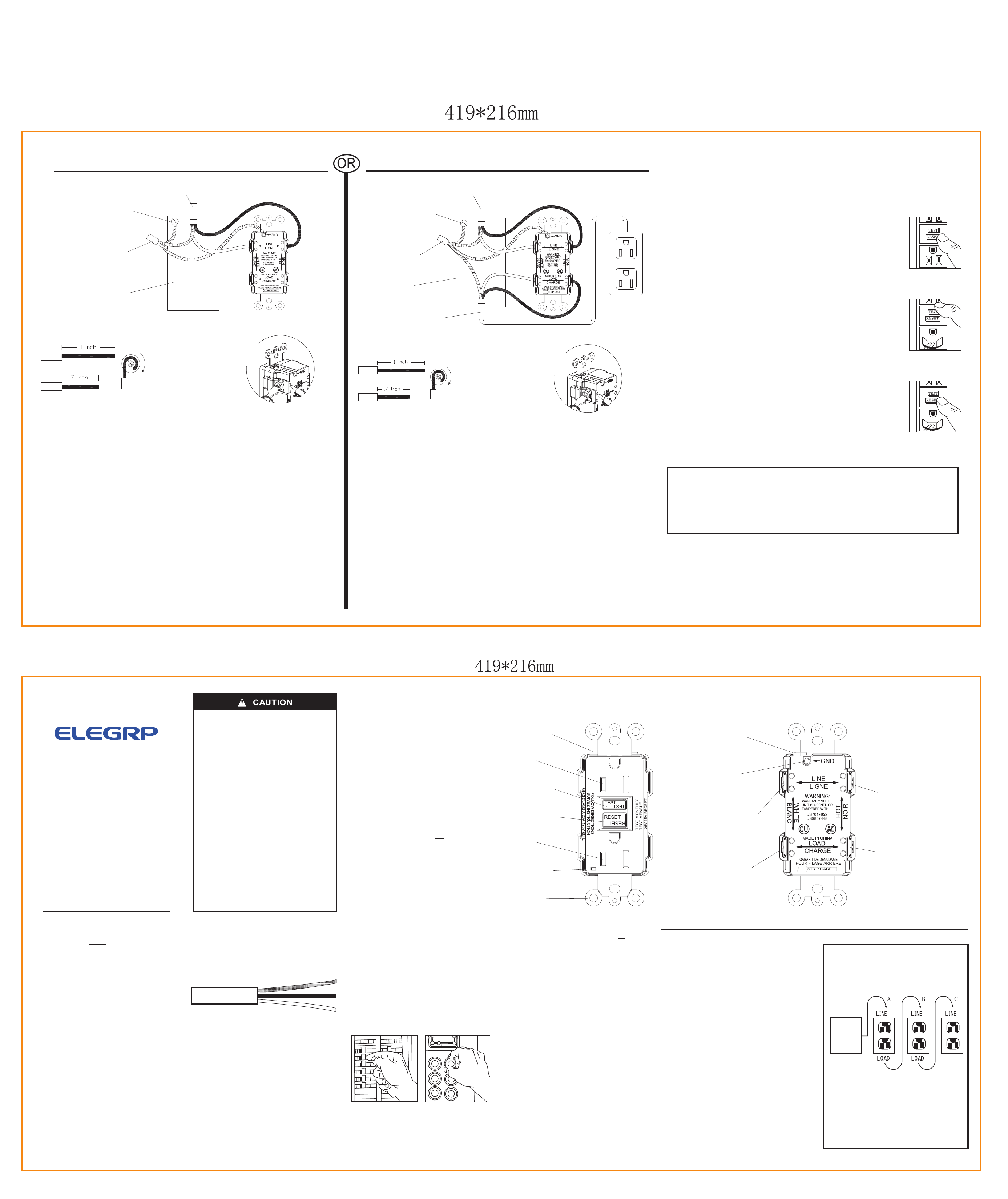
2. The GFCI's features-
FRONT VIEW
Outlet
Outlet
Test Button:
See step 8
Reset Button:
See step 8
Receptacle
LED Indicator
Light
Mounting
Bracket
Grounding terminal (Green):
Connection for bare
copper or green wire
Grounding terminal
back wire slot
LINE
White terminal (Silver):
Connection for the LINE
cable's white wire
LOAD
White terminal (Silver):
Connection for the
LOAD cable's white
wire
Screw (terminal) colors:
Green = grounding terminal
Silver = white terminals
Brass = hot terminals
LINE
Hot terminal (Brass):
Connection for the
LINE cable's black
wire
LOAD
Hot terminal (Brass):
Connection for the
LOAD cable's black
wire
BACK VIEW
3. Should you install it?
Installing a GFCI receptacle can be more
complicated than installing a conventional
receptacle.
Make sure that you:
• Understand basic wiring principles and
techniques
• Can interpret wiring diagrams
• Have circuit wiring experience
• Are prepared to take a few minutes to
test your work, making sure that you
have wired the GFCI receptacle
correctly
4. LINE vs. LOAD
A cable consists of 2 or 3 wires.
Cable Wires
LINE cable:
Delivers power from the service panel
(breaker panel or fuse box) to the GFCI.
If there is only one cable entering the
electrical box, it is the LINE cable. This
cable should be connected to the GFCI's
LINE terminals only.
LOAD cable:
Delivers power from the GFCI to another
receptacle in the circuit. This cable should
be connected to the GFCI's LOAD terminals
only.
5. Turn the power OFF
Plug an electrical device, such as a lamp
or radio, into the receptacle on which you
are working. Turn the lamp or radio on.
Then, go to the service panel. Find the
breaker or fuse that protects that receptacle.
Place the breaker in the OFF position or
completely remove the fuse. The lamp or
radio should turn OFF.
Next, plug in and turn ON the lamp or radio
at the receptacle's other outlet to make sure
the power is OFF at both outlets. If the
power is not OFF, stop work and call an
electrician to complete the installation.
6. Identify cables/wires-
Important:
DO not install the GFCI receptacle in an
electrical box containing (a) more than 4
wires (not including the grounding wires)
or (b) cables with more than two wires
(not including the grounding wire). Contact
a qualified electrician if either (a) or (b) is
true.
If you are replacing an old receptacle,
pull it out of the electrical box without
disconnecting the wires.
• If you see one cable (2-3 wires), it is the
LINE cable. The receptacle is probably in
position C (see diagram to the right).
Remove the receptacle and go to step 7A.
• If you see two cables (4-6 wires), the
receptacle is probably in position A or B
(see diagram to the right). Follow steps
a-e of the procedure to the right.
Procedure: box with two cables
(4-6 wires)
(a) Detach one cable's white and hot wires
from the receptacle and cap each one
separately with a wire connector. Make
sure that they are from the same cable.
(b) Re-install the receptacle in the electrical
box, attach the faceplate, then turn the
power ON at the service panel.
(c) Determine if power is flowing to the
receptacle. If so the capped wires are the
LOAD wires. If not the capped wires are
the LINE wires.
(d) Turn the power OFF at the service panel,
label the LINE and LOAD wires, then
remove the receptacle.
(e) Go to step 7B.
Placement in circuit:
The GFCI's place in the circuit determines
if it protects other receptacles in the
circuit.
Sample circuit:
Placing the GFCI in position A will also
provide protection to "load side"
receptacles B and C. On the other hand,
placing the GFCI in position C will not
provide protection to receptacles A or B.
Remember that receptacles A, B and C
can be in different rooms.
Service
Panel
7. Connect the wires (choose A or B)... only after reading other side completely
LINE cable brings
power to the GFCI
Ground connection
to box (if box has a
ground terminal)
Wire connector
Electrical box
About wire connections:
Screw Terminal
Wire
Back Wire Holes
Wire
Side Wire
Clockwise, 2/3
of the way
around screw
Connect the LINE cable wires to the LINE terminals:
• The white wire connects to the White terminal (Silver)
• The black wire connects to the Hot terminal (Brass)
Connect the grounding wire (only if there is a grounding wire):
• For a box with no grounding terminal: (diagram not shown) Connect the LINE cable's
bare copper (or green) wire directly to the grounding terminal on the GFCI receptacle.
• For a box with a grounding terminal: (diagram shown above) Connect a 6-inch bare
copper (or green) 12 or 14 AWG wire to the grounding terminal (green) on the GFCI.
Also connect a similar wire to the grounding terminal on the box. Connect the ends of
these wires to the LINE cable's bare copper (or green) wire using a wire connector. If
these wires are already in place, check the connections.
Complete the installation:
• Fold the wires into the box, keeping the grounding wire away from the White and Hot
terminals. Screw the receptacle to the box and attach the faceplate.
• Go to step 8.
Connect the LINE cable wires to the LINE terminals:
• The white wire connects to the White terminal (Silver)
• The black wire connects to the Hot terminal (Brass)
Connect the LOAD cable wires to the LOAD terminals:
• The white wire connects to the White terminal (Silver)
• The black wire connects to the Hot terminal (Brass)
Connect the grounding wires as shown above (only if there is a grounding wire):
• Connect a 6-inch bare copper (or green) 12 or 14 AWG wire to the grounding terminal
(green) on the GFCI. If the box has a grounding terminal, also connect a similar wire to
the grounding terminal on the box. Connect the ends of these wires to the LINE and
LOAD cable's bare copper (or green) wire using a wire connector. If these wires are
already in place, check the connections.
Complete the installation:
• Fold the wires into the box, keeping the grounding wire away from the White and Hot
terminals. Screw the receptacle to the box and attach the faceplate.
• Go to step 8.
Grounding connection
to box (if box has a
ground terminal)
LINE cable brings
power to the GFCI
Wire connector
Electrical box
LOAD cable feeds power
to other receptacle(s)
About wire connections:
Screw Terminal
Wire
Back Wire Holes
Wire
Side Wire
Clockwise, 2/3
of the way
around screw
8. Test your work
Why perform this test?
• If you miswired the GFCI, it may not prevent personal injury or death due to a ground
fault (electrical shock).
• If you mistakenly connect the line wires to the Load terminals, the GFCI will provide
no power.
Procedure:
(a)
Turn the power ON at the service panel. Press the RESET button fully.
The RESET button should stay in. The LED load side voltage indicator
will illuminate green in color. If the RESET button does not stay in, go
to Troubleshooting. If the RESET button stays in, plug a lamp or radio
into the GFCI (and leave it plugged in) to verify that the power is ON.
If there is no power, go to Troubleshooting.
(b) Press the TEST button in order to trip the device. This should stop the
flow of electricity, making the radio or lamp shut OFF. The Green LED
load side voltage indicator will turn OFF. Note that the RESET button
will pop-out. If the power stays ON, go to Troubleshooting. If the
power goes OFF, you have installed the GFCI receptacle correctly. To
restore power, press the RESET button.
(c) If you installed your GFCI using step 7B, plug a lamp or radio into
surrounding receptacles to see which one(s), in addition to the GFCI,
lost power when you pressed the TEST button. Do Not plug life saving
devices into any of the receptacles that lost power. Place a
"GFCI PROTECTED OUTLET" sticker on every receptacle that lost
power. Then press the RESET button to reset the GFCI.
(d) Press the TEST button(then RESET button)every month to assure
proper operation. If the GFCI can not be reset, then it must be replaced.
(e) This is an auto-monitoring GFCI receptacle. It conducts an automatic
test every 5 seconds, ensuring it is always ready to provide protection.
The GFCI receptacle has reached its end of life when the GFCI:
1 – repeatedly trips when RESET is attempted
2 – does not permit power to the load with an audible "clicking" sound or
3 – denial of power to the load (trip with the inability to RESET)
.
TROUBLESHOOTING
Turn the power OFF and check the wire connections against the appropriate wiring
diagram in step 7A or 7B. Make sure that there are no loose wires or loose connections.
Also, it is possible that you reversed the LINE and LOAD connections. LINE/LOAD
reversal will be indicated by power remaining OFF at the GFCI Face and by the Reset
Button not staying in. Reverse the LINE and LOAD connections if necessary. Start the
test from the beginning of step 8 if you rewired any connections to the GFCI.
General Information
GFCI Rating:
15A: Receptacle rated 15A
Feed through 20A
20A: Receptacle rated 20A
Feed through 20A
Warranty:
If within one year from the date of purchase this G.F.C.I.
unit fails due to a defect in material or workmanship only,
we will replace it free of charge. The warranty does not
apply to cases where damage has been due to faulty
installation, abuse, misuse, or unauthorized tampering
and/or repair.
1. Insert wire to
bottom of hole
2. Securely tighten
screw beneath wire
hole to retain
inserted wire
1. Insert wire to
bottom of hole
2. Securely tighten
screw beneath wire
hole to retain
inserted wire
ELE GROUP CO., LTD
————————————————————
NO.158 CHUANGYUAN ROAD, SIP
SUZHOU, JIANGSU, CHINA 215125
WWW.ELEGRP.COM