ColeMan and AirXcel (same)
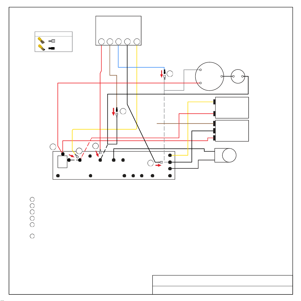
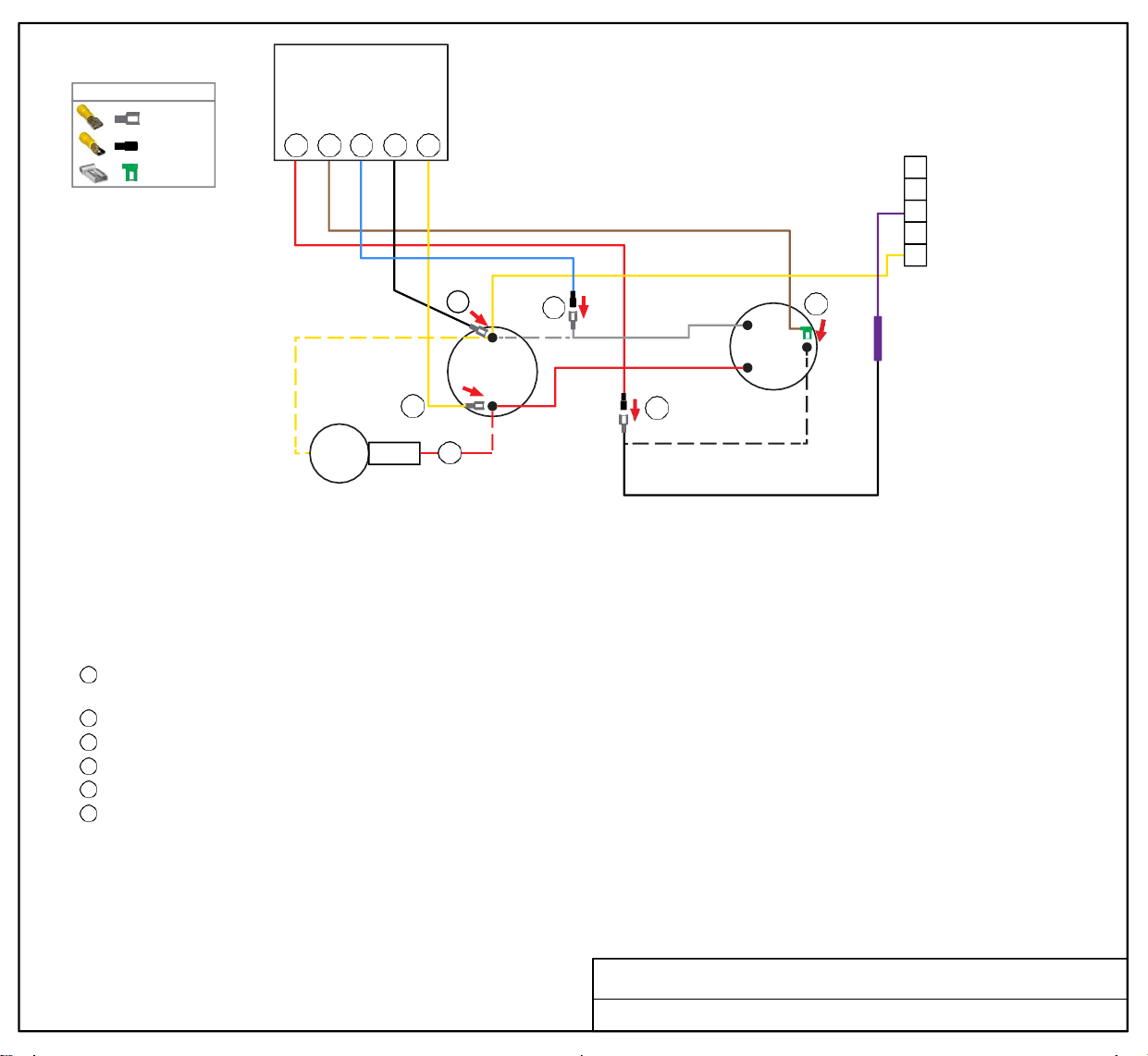
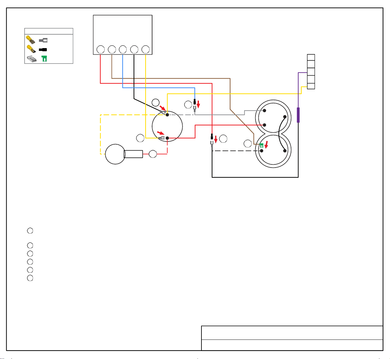
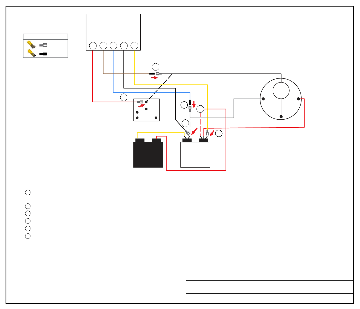
1970A999
1971-
984
1976-
204
1976-
345
1976-
518
1976-
568
1976-
603
1976-
613
1976-
724
1976-
731
1976-
734
1976-
736
1976-
740
1976-
741
1976-
742
1976-
743
1976-
760
1976-
761
1976-
762
1976-
763
1976-
764
1976A061
1976A096
1976A136
1976A363
1976A364
1976A518
1976A519
1976A536
1976A537
1976A603
1976A613
1976A727
1976A736
1976A738
1976A742
1976B031
1976B037
1976B119
1976B136
1976B519
1976B603
1976B613
1976C136
1976C304
1976C519
1976C613
1976D136
1976D519
1976E136
1976E304
1976E519
1976E519
MODIFIED
7-22
1976F304
1976G304
N22531
Soft
Start
5 6 1 2 3
5
BLACK
6
RED
2
1
4
1 5
2
WHITE
OL
R S
C
COMPRESSOR
WHITE
3
RED COMPRESSOR WIRE
START
CAPACITOR
C HERM
RUN
CAPACITOR
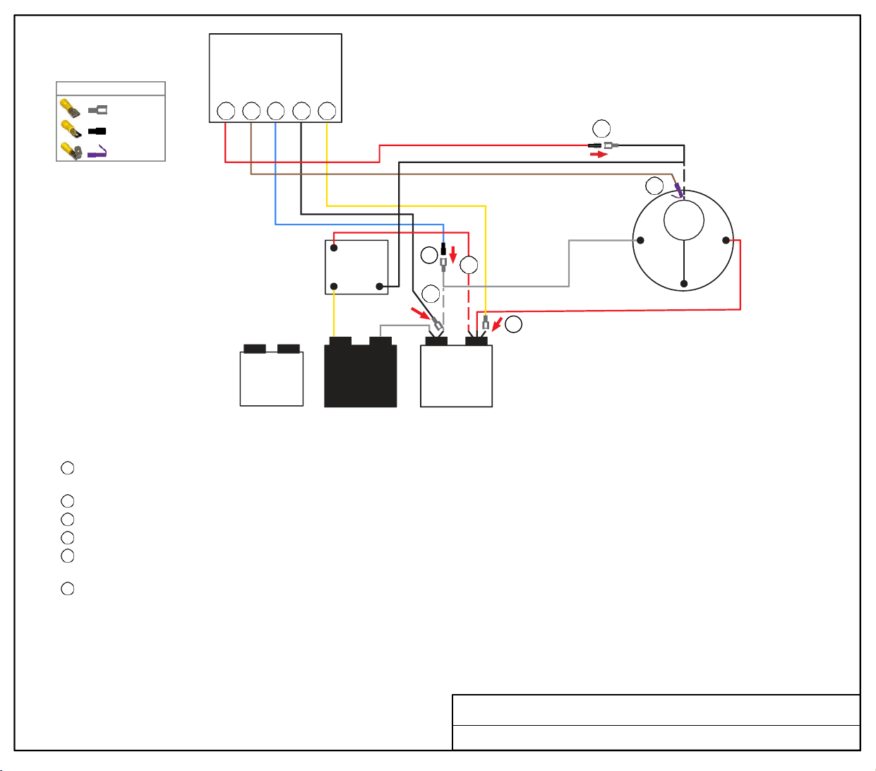
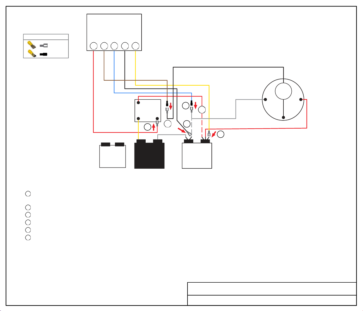
TURN ALL POWER OFF BEFORE STARTING INSTALLATION.
Route Blue, Black and Yellow SoftStart wires into the electrical box. Then crimp Connectors onto all SoftStart wires as indicated in drawing.
Step
1
Step
2
Step 3
Step
4
Step 5
Step 6
Follow White Compressor Wire from Compressor to Run Capacitor “C” terminal. Disconnect from “C” terminal and connect it to Blue
SoftStart wire.
Connect Black SoftStart wire to the terminal that the White Compressor Wire was on.
Connect Yellow SoftStart wire on terminal next to Red Compressor Wire on "Herm" Side of Run Capacitor.
IF you have three Capacitors or see a second Red wire next to the Red Compressor Wire, disconnect it and seal end with electrical tape.
Remove Compressor cap. Disconnect Blue Compressor Wire and connect to Red SoftStart wire. Tape connection.
NOTE: This connection will not be under the cap when the cap is replaced.
Break male tangent off piggyback connector, then bend female connector at 90º angle. Connect Brown SoftStart wire onto the terminal
that the Black Compressor Wire was on. Route wire to exit cap with Red and White wires. Replace cap.
Secure all wires. Tape connections with electrical tape.
Turn Power and A/C Breaker on. Turn A/C to Auto Cool setting and set the thermostat to 55ºF.
Look at SoftStart LED lights. Green light should be “on”. Green light means the Compressor is running (there may be a full 3-minute delay before
Green light comes on). IF there is no Green light after 4 minutes, call SoftStart Tech Support for assistance.
After establishing Green light operation, re-install all A/C covers.
Turn A/C on, set near to outdoor temperature and run for 30 minutes.
After 30 minutes, operate A/C normally.
Wiring Diagram for Coleman Mach 1970A999 (11-75)
FEMALE
MALE
PIGGYBACK
WIRE CONNECTOR GUIDE
FAN
CAPACITOR
MALE
RED
PIGGYBACK
BROWN
MALE
BLUE
FEMALE
BLACK
FEMALE
YELLOW
Soft
Start
6 5 1 2 3
BLACK
RED
2
1
RELAY
4
1 5
6
5 2
WHITE
OL
R S
C
COMPRESSOR
WHITE
3
RED COMPRESSOR WIRE
START
CAPACITOR
C HERM
RUN
CAPACITOR
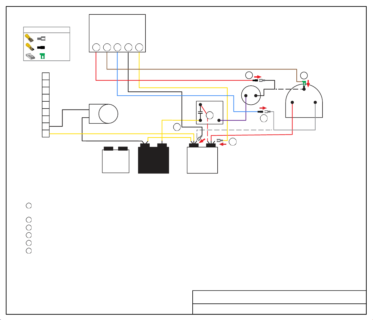
TURN ALL POWER OFF BEFORE STARTING INSTALLATION.
Route all SoftStart wires into the electrical box. Then crimp Connectors onto all SoftStart wires as indicated in drawing.
Step
1
Step 2
Step 3
Step 4
Step 5
Step 6
Follow White Compressor Wire from Compressor to Run Capacitor “C” terminal. Disconnect from “C” terminal and connect it to Blue
SoftStart wire. Tape connection with electrical tape.
Connect Black SoftStart wire to the terminal that the White Compressor Wire was on.
Connect Yellow SoftStart wire on terminal next to Red Compressor Wire on "Herm" Side of Run Capacitor.
IF you have three Capacitors or see a second Red wire next to the Red Compressor Wire, disconnect it and seal end with electrical tape.
Follow Black Compressor Wire to Relay. Disconnect Black wire and connect to Brown SoftStart wire. Tape connection.
Connect Red SoftStart wire onto the terminal that the Black Compressor Wire was on.
Secure all wires. Tape connections with electrical tape.
Turn Power and A/C Breaker on. Turn A/C to Auto Cool setting and set the thermostat to 55ºF.
Look at SoftStart LED lights. Green light should be “on”. Green light means the Compressor is running (there may be a full 3-minute delay before
Green light comes on). IF there is no Green light after 4 minutes, call SoftStart Tech Support for assistance.
After establishing Green light operation, re-install all A/C covers.
Turn A/C on, set near to outdoor temperature and run for 30 minutes.
After 30 minutes, operate A/C normally.
Wiring Diagram for Coleman Mach 1971-984 (10-81)
FEMALE
MALE
WIRE CONNECTOR GUIDE
RED
FAN
CAPACITOR
FEMALE
BROWN
MALE
BLUE
MALE
BLACK
FEMALE
YELLOW
FEMALE
Soft
Start
5 6 1 2 3
9
5
6
8
BLACK
7
COMPRESSOR
6
5 2
RELAY
4
4
C
FREEZE
S R
SWITCH
3
2
REVERSING
VALVE
1
2
START
CAPACITOR
1 5
3
C HERM
RUN
CAPACITOR
1
RED COMPRESSOR WIRE
WHITE
TURN ALL POWER OFF BEFORE STARTING INSTALLATION.
Route Blue, Black and Yellow SoftStart wires into the electrical box. Route Brown and Red SoftStart wires to the top of the Compressor.
Then crimp Connectors onto all SoftStart wires as indicated in drawing.
Step 1
Step 2
Step 3
Step 4
Step 5
Step 6
Follow White Compressor Wire from Compressor to Run Capacitor “C” terminal. Disconnect from “C” terminal and connect it to Blue
SoftStart wire. Tape connection with electrical tape.
Connect Black SoftStart wire to the terminal that the White Compressor Wire was on.
Connect Yellow SoftStart wire on terminal next to Red Compressor Wire on "Herm" Side of Run Capacitor.
Disconnect the Red wire from the Run Capacitor that goes to the Start Relay. Seal end with electrical tape and drop it.
Remove the Compressor Cap. Disconnect Black wire and connect to Red SoftStart wire. Tape connection. (Wires do not go back under cap.)
Connect Brown SoftStart wire (with Female Flag connector) onto the terminal that the Black Compressor Wire was on.
Secure all wires. Tape connections with electrical tape.
Turn Power and A/C Breaker on. Turn A/C to Auto Cool setting and set the thermostat to 55ºF.
Look at SoftStart LED lights. Green light should be “on”. Green light means the Compressor is running (there may be a full 3-minute delay before
Green light comes on). IF there is no Green light after 4 minutes, call SoftStart Tech Support for assistance.
After establishing Green light operation, re-install all A/C covers.
Turn A/C on, set near to outdoor temperature and run for 30 minutes.
After 30 minutes, operate A/C normally.
Wiring Diagram for Coleman Mach 1976-204 (03-95)
FEMALE
MALE
FEMA LE FLAG
WIRE CONNECTOR GUIDE
FAN
CAPACITOR
RED
MALE
FEMALE
FLAG
BROWN
BLUE
MALE
BLACK
FEMALE
YELLOW
FEMALE

FEMALE
MALE
FEMA LE FLAG
WIRE CONNECTOR GUIDE
5 6 1 2 3
Soft
Start
COMPRESSOR
6
5
C
REVERSING
VALVE
4
3
2
1
FREEZE
SWITCH
1
4
2
3
BLACK
R
WHITE
S
START
CAPACITOR
C HERM
RUN
CAPACITOR
RED COMPRESSOR WIRE
TURN ALL POWER OFF BEFORE STARTING INSTALLATION.
Route Blue, Black and Yellow SoftStart wires into the electrical box. Route Brown and Red SoftStart wires to the top of the Compressor.
Then crimp Connectors onto all SoftStart wires as indicated in drawing
IF there are 3 Capacitors, follow Step 4. If there are not three Capacitors, skip Step 4.
Step 1
Step 2
Step 3
Step 4
Step 5
Step 6
Follow White Compressor Wire from Compressor to Run Capacitor “C” terminal. Disconnect from “C” terminal and connect it to Blue
SoftStart wire. Tape connection with electrical tape.
Connect Black SoftStart wire to the terminal that the White Compressor Wire was on.
Connect Yellow SoftStart wire on terminal next to Red Compressor Wire on "Herm" side of Run Capacitor.
IF there is a second Red wire next to the Red Compressor wire, disconnect it, seal end with electrical tape and drop it.
Remove the Compressor Cap. Disconnect Black wire and connect to Red SoftStart wire. Tape connection. (Wires do not go back under cap.)
Connect Brown SoftStart wire (with Female Flag connector) onto the terminal that the Black Compressor Wire was on. Route Brown wire
out with Red and White Compressor wires. Replace cap.
Secure all wires. Tape connections with electrical tape.
Turn Power and A/C Breaker on. Turn A/C to Auto Cool setting and set the thermostat to 55ºF.
Look at SoftStart LED lights. Green light should be “on”. Green light means the Compressor is running (there may be a full 3-minute delay before
Green light comes on). IF there is no Green light after 4 minutes, call SoftStart Tech Support for assistance.
After establishing Green light operation, re-install all A/C covers.
Turn A/C on, set near to outdoor temperature and run for 30 minutes.
After 30 minutes, operate A/C normally.
Wiring Diagram for Coleman Mach 1976--345 (02-01)
RED
FAN
CAPACITOR
MALE
BROWN
FEMALE
FLAG
BLUE
MALE
BLACK
FEMALE
YELLOW
FEMALE
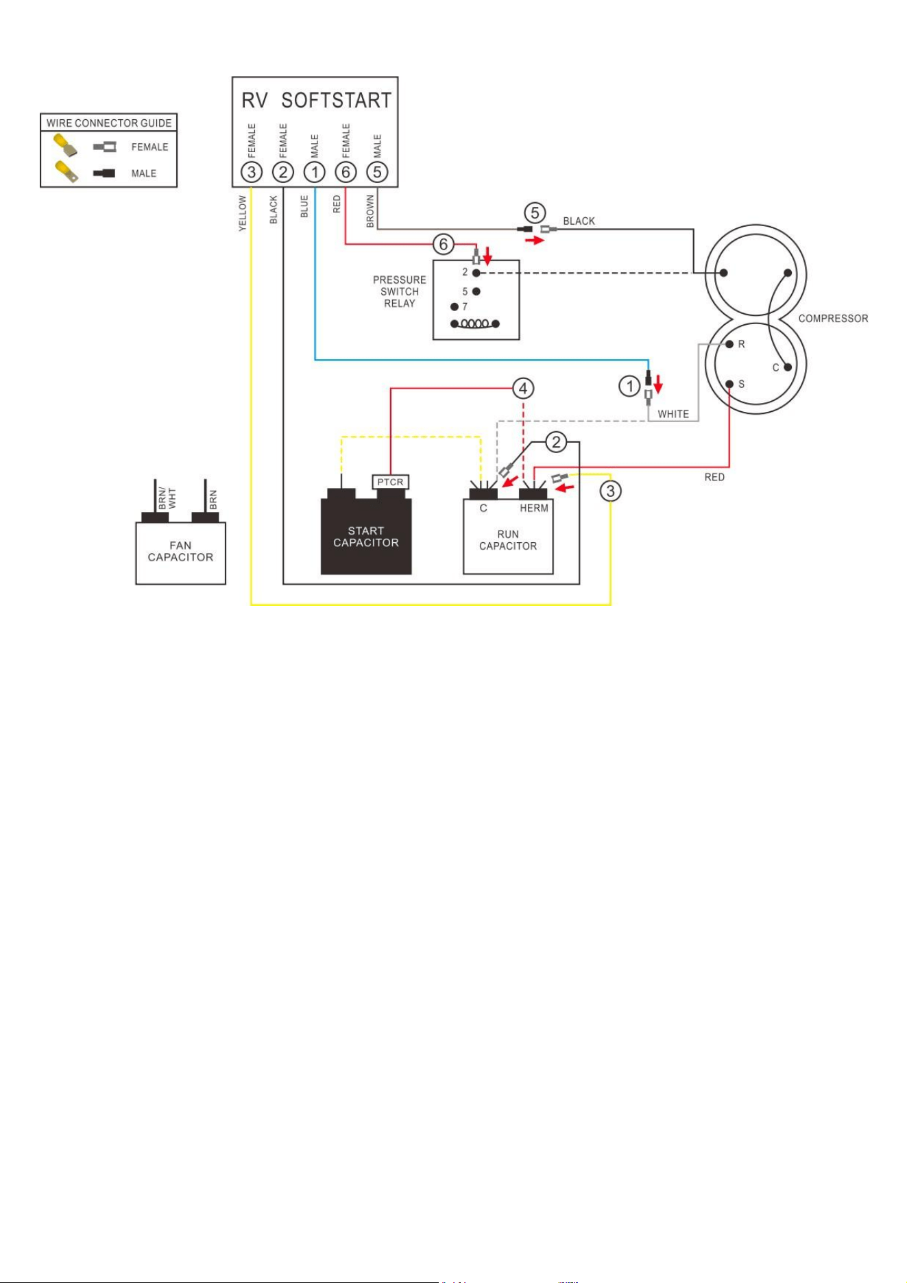
Wiring Diagram for Coleman Mach 1976-518

Coleman Mach 1976-518
Step 1. Follow White Compressor wire from Compressor to Run Capacitor “C” terminal. Disconnect
from “C” terminal and connect it to Blue SoftStart wire. Tape connection with electrical tape.
Step 2. Connect Black SoftStart wire to the terminal that the White Compressor wire was on.
Step 3. Connect Yellow SoftStart wire on terminal next to Red Compressor wire on HERM terminal of
Run Capacitor.
Step 4. IF there is a second Red wire next to the Red Compressor wire, disconnect it, seal end with
electrical tape and drop it.
Step 5. Follow Black Compressor wire to Pressure Switch Relay terminal. Disconnect it and connect to
Brown SoftStart wire. Tape connection.
Step 6. Connect Red SoftStart wire onto the terminal that the Black Compressor wire was on.
Secure all wires. Tape connections with electrical tape.
Turn Power and A/C Breaker on. Turn A/C to Auto Cool setting and set the thermostat to 55ºF.
Look at SoftStart LED lights. Green light should be “on”. Green light means the Compressor is
running (there may be a full 3-minute delay before Green light comes on). IF there is no Green light
after 4 minutes, call SoftStart Tech Support for assistance.
After establishing Green light operation, re-install all A/C covers.
Turn A/C on, set near to outdoor temperature and run for 30 minutes. After 30 minutes, operate A/C
normally.
WHITE
BLACK
ORG
PUR
Soft
Start
6B 5B 1B 2B 3B
6A
5A
5B 6B
1A
4A
2A
2B
1B
4B
PTCR
C
START
CAPACITOR
RUN
CAPACITOR
3A
HERM
B
3B
FAN
S
S
R C
C
R
COMPRESSOR
A
COMPRESSOR
B
TURN ALL POWER OFF BEFORE STARTING INSTALLATION.
Route ALL SoftStart wires into the electrical box. Then crimp Connectors onto all SoftStart wires as indicated in drawing.
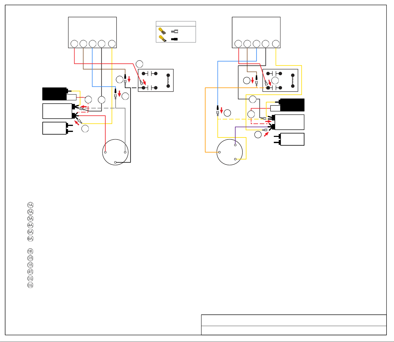
NOTE: Instructions are separate for Compressors A and B because wires colors are different. Work with one Compressor and one SoftStart at a time to avoid confusion.
COMPRESSOR A INSTRUCTIONS
Step Follow White Compressor wire to "C" terminal of Run Capacitor. Disconnect and connect to Blue SoftStart wire. Tape connection.
Step Connect Black SoftStart wire to the terminal on the Run Capacitor that the White Compressor Wire was on.
Step Connect Yellow SoftStart wire on a terminal next to the Red Compressor wire.
Step Disconnect the PTCR Red wire from the Herm Run Capacitor. Seal end with electrical tape and drop it.
Step Follow Black compressor wire to the relay. Disconnect and connect to the Brown SoftStart wire. Tape connection.
Step Connect the Red SoftStart wire on the Terminal the Black Compressor wire was on.
COMPRESSOR B INSTRUCTIONS
Step Follow the Yellow Compressor wire to the "C" terminal of the Run Capacitor. Disconnect and connect to the Blue SoftStart wire.
Step Connect Black SoftStart wire to the terminal on the Run Capacitor that the Yellow Compressor wire was on.
Step Connect the Yellow SoftStart wire on a terminal next to the Purple Compressor wire on the Herm terminals.
Step Disconnect the PTCR Red wire from the Herm Run Capacitor. Seal end with electrical tape and drop it.
Step Follow Orange Compressor wire to the relay. Disconnect and connect to the Brown SoftStart wire. Tape connection.
Step Connect the Red SoftStart wire on the terminal that the Orange Compressor wire was on.
Secure all wires. Tape connections with electrical tape.
Turn Power and A/C Breaker on. Turn A/C to Auto Cool setting and set the thermostat to 55ºF.
Look at SoftStart LED lights. Green light should be “on”. Green light means the Compressor is running (there may be a full 3-minute delay before Green light comes on). IF there
is no Green light after 4 minutes, call SoftStart Tech Support for assistance.
After establishing Green light operation, re-install all A/C covers. Turn A/C on, set near
to outdoor temperature and run for 30 minutes. After 30 minutes, operate A/C normally.
Wiring Diagram for Coleman Dual Basement 1976-568 (5-16)
FEMALE
MALE
WIRE CONNECTOR GUIDE
FAN
C
HERM
PTCR
RUN
CAPACITOR
A
6A 5A 1A 2A 3A
START
CAPACITOR
Soft
Start
RED
FEMALE
BROWN
MALE
BLUE
MALE
BLACK
FEMALE
RED
FEMALE
YELLOW
RED
FEMALE
BROWN
MALE
BLUE
YEL
MALE
BLACK
FEMALE
YELLOW
FEMALE
Soft
Start
FAN
MOTOR
BLACK COMPRESSOR WIRE
COMPRESSOR
6 5 1 2 3
WHITE
BLACK
WHITE
R
C
S
1
6
RED
5
2
YELLOW
PRESSURE
SWITCH
RELAY
C HERM
RUN
CAPACITOR
START
CAPACITOR
RED
4 3
PTCR
WHT
PTCR
BLK
ORG
RED
BLU
PUR
YEL
REVERSING
VALVE
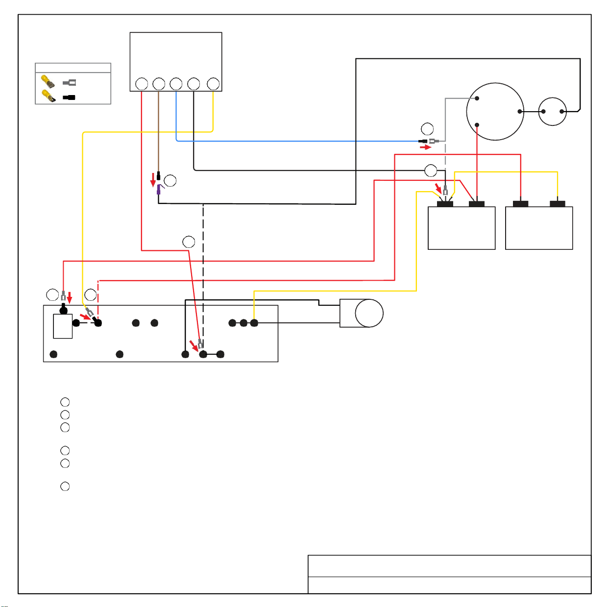
TURN ALL POWER OFF BEFORE STARTING INSTALLATION.
Route ALL SoftStart wires into the electrical box. Then crimp Connectors onto all SoftStart wires as indicated in drawing.
Step
1
Step 2
Step 3
Step 4
Step 5
Step 6
Follow White Compressor wire to Run Capacitor. Disconnect from Run Capacitor and connect to Blue SoftStart wire.
Connect Black SoftStart wire to the terminal on the Run Capacitor that the White Compressor Wire was on.
Disconnect single Red wire next to PTCR (running from Start Capacitor) and tape end with electrical tape. Connect Yellow SoftStart
wire on terminal that the Red wire was on.
Disconnect PTCR. Disconnect Red wire from PTCR and connect Red wire on terminal that the PTCR was on.
Follow Black Compressor Wire to Pressure Switch Relay and disconnect it from Relay. Also, disconnect Black Fan wire from Black
Compressor wire. Connect Black Compressor wire to Brown SoftStart wire and tape connection with electrical tape.
Connect Red SoftStart wire to Pressure Switch Relay. Connect Black Fan wire to male Terminal on Red SoftStart (use piggyback
connector).
Secure wires to prevent Fan from pulling wires in. Tape connections with electrical tape.
Turn Power and A/C Breaker on. Turn A/C to Auto Cool setting and set the thermostat to 55ºF.
Look at SoftStart LED lights. Green light should be “on”. Green light means the Compressor is running (there may be a full 3-minute delay
before Green light comes on). IF there is no Green light after 4 minutes, call SoftStart Tech Support for assistance.
After establishing Green light operation, re-install all A/C covers.
Turn A/C on, set near to outdoor temperature and run for 30
minutes. After 30 minutes, operate A/C normally.
Wiring Diagram for Coleman Mach 1976-603 (3-12)
FEMALE
MALE
PIGGYBACK
WIRE CONNECTOR GUIDE
RED
PIGGYBACK
BROWN
MALE
BLUE
MALE
BLACK
FEMALE
YELLOW
FEMALE
RED
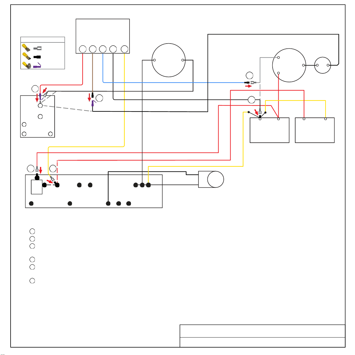
6 5 1 2 3
Soft
Start
BLACK COMPRESSOR WIRE
COMPRESSOR
WHITE
R
C
S
1
RED
2
5
YELLOW
6
RED
C HERM
RUN
CAPACITOR
START
CAPACITOR
4 3
PTCR
WHT
PTCR
BLK
ORG
RED
BLU
PUR
YEL
REVERSING
VALVE
TURN ALL POWER OFF BEFORE STARTING INSTALLATION.
Route ALL SoftStart wires into the electrical box. Then crimp Connectors onto all SoftStart wires as indicated in drawing.
Step
1
Step 2
Step 3
Step 4
Step 5
Step 6
Follow White Compressor wire to Run Capacitor. Disconnect from Run Capacitor and connect to Blue SoftStart wire.
Connect Black SoftStart wire to the terminal on the Run Capacitor that the White Compressor Wire was on.
Disconnect single Red wire next to PTCR (running from Start Capacitor) and tape end with electrical tape. Connect Yellow SoftStart
wire on terminal that the Red wire was on.
Disconnect PTCR. Disconnect Red wire from PTCR and connect Red wire on terminal that the PTCR was on.
Follow Black Compressor Wire to the terminal by PUR on the terminal board. Disconnect it, then connect Black Compressor wire to
Brown SoftStart wire and tape connection with electrical tape.
Connect Red SoftStart wire to the terminal that the Black Compressor Wire was on.
Secure wires to prevent Fan from pulling wires in. Tape connections with electrical tape.
Turn Power and A/C Breaker on. Turn A/C to Auto Cool setting and set the thermostat to 55ºF.
Look at SoftStart LED lights. Green light should be “on”. Green light means the Compressor is running (there may be a full 3-minute delay
before Green light comes on). IF there is no Green light after 4 minutes, call SoftStart Tech Support for assistance.
After establishing Green light operation, re-install all A/C covers.
Turn A/C on, set near to outdoor temperature and run for 30
minutes. After 30 minutes, operate A/C normally.
Wiring Diagram for Coleman Mach 1976-613 (7-12)
FEMALE
MALE
WIRE CONNECTOR GUIDE
FEMALE
RED
MALE
BROWN
MALE
BLUE
FEMALE
BLACK
FEMALE
YELLOW
RED
Soft
Start
WIRE CONNECTOR GUIDE
FEMALE
MALE
REVERSING
VALVE
3 2 1
6 5
OUTDOOR
TEMP
BOARD
RELAY
NC NO
COM
6
PRESSURE
2
SWITCH
RELAY
5
7
5
BLACK
R
C
S
2
1
START
CAPACITOR
4
2
3
C HERM
RUN
CAPACITOR
WHITE
1
RED
COMPRESSOR
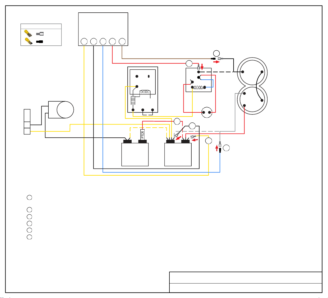
TURN ALL POWER OFF BEFORE STARTING INSTALLATION.
Route all SoftStart wires into the electrical box. Then crimp Connectors onto all SoftStart wires as indicated in drawing
Step 1
Step 2
Step 3
Step 4
Step 5
Step 6
Follow White Compressor Wire from Compressor to Run Capacitor “C” terminal. Disconnect from “C” terminal and connect it to Blue
SoftStart wire. Tape connection with electrical tape.
Connect Black SoftStart wire to the terminal that the White Compressor Wire was on.
Connect Yellow SoftStart wire on terminal next to Red Compressor Wire on "HERM" terminal of Run Capacitor.
IF there is a second Red wire next to the Red Compressor wire, disconnect it, seal end with electrical tape and drop it.
Follow Black Compressor Wire to Pressure Switch Relay. Disconnect it and connect to Brown SoftStart wire. Tape connection.
Connect Red SoftStart wire onto the terminal that the Black Compressor Wire was on.
Secure all wires. Tape connections with electrical tape.
Turn Power and A/C Breaker on. Turn A/C to Auto Cool setting and set the thermostat to 55ºF.
Look at SoftStart LED lights. Green light should be “on”. Green light means the Compressor is running (there may be a full 3-minute delay before
Green light comes on). IF there is no Green light after 4 minutes, call SoftStart Tech Support for assistance.
After establishing Green light operation, re-install all A/C covers.
Turn A/C on, set near to outdoor temperature and run for 30
minutes. After 30 minutes, operate A/C normally.
Wiring Diagram for Coleman Mach 1976-724 (4-15)
YELLOW
FEMALE
BLACK
FEMALE
BLUE
MALE
RED
MALE
FEMALE
FLAG
BROWN
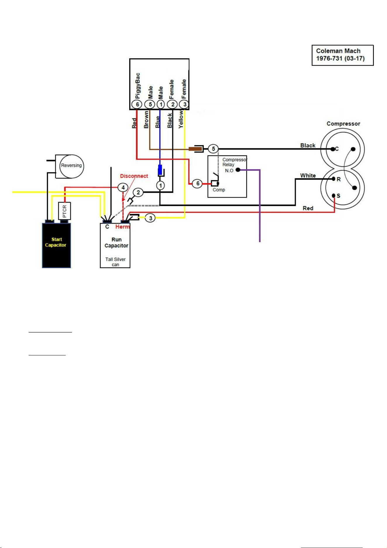
Coleman Mach 1976-731
COLEMAN
1976-
731
Route All SoftstartRV wires into the electrical box. Crimp a connector on the wires as indicated
in the
Softstart box at the top of the drawing.
Step 1) Follow the White compressor wire to the “C” terminal of the RUN Capacitor. Disconnect and
connect it to the Blue SoftstartRV wire.
Step 2) Connect the Black SoftstartRV wire on the terminal the White compressor wire was on.
Step 3) Follow the Red compressor wire from the compressor to the “HERM” terminal. DO
NOT DISCONNECT RED COMPRESSOR WIRE
. Connect the Yellow SoftstartRV wire on the
Terminal next to the Red compressor wire if it is available (see next step).

Coleman Mach 1976-731
Step 4) IF you see a 2nd Red wire next to the Red compressor wire DISCONNECT it, tape the end and
drop it. Then connect the Yellow SoftstartRV wire on the Terminal where you pulled the second
Red wire o .
Step 5) Follow the Black compressor wire to the Compressor relay where it has a second Black wire
piggybacked on to it. Pull o the second Black wire that was piggybacked to the Black Compressor
wire. Connect the Brown SoftstartRV wire to the Black compressor wire.
Step 6) Connect the Red SoftstartRV wire (you have already put a piggyback connector on it) to the
Relay Terminal where you pulled the Black Compressor o . Now take the loose Black wire and put
it on the piggyback Red SoftstartRV wire.
Before turning the power back on, secure wires to prevent the fan from pulling them in. Turn Power
and A/C breaker on, Turn Fan on High until you hear it running, Turn A/C to Auto Cool set
Thermostat to 55 degrees.
Look at the SoftstartRV for a Green light (There may be a full 3 min delay before the Green
light comes on).
When you see the Green Light, Turn the power o and replace all covers then turn the A/C back
on
and allow it to run for 30 min at about 2 degrees below the outside temperature whichshould give
it time to cycle a few times.
Soft
Start
WIRE CONNECTOR GUIDE
FEMALE
MALE
6 5 1 2 4
COMPRESSOR
RED
WHITE
R
1
C
S
BLACK
YELLOW
5 RED
START
CAPACITOR
3
PTCR
6
4
WHT
BROWN
BLACK
RED
BLACK
2
BLACK
FAN
C
HERM
RUN
CAPACITOR
WHT
PTCR FREEZE
ORG
BLK
RED
BLU
PUR BWN
TERMINAL
BOARD
REVERSING
VALVE
TURN ALL POWER OFF BEFORE STARTING INSTALLATION.
Route ALL SoftStart wires into the electrical box. Then crimp Connectors onto all SoftStart wires as indicated in drawing.
Step
1
Step 2
Step 3
Step 4
Step 5
Step 6
Follow White Compressor wire to Terminal Board. Disconnect from Terminal Board and connect to Blue SoftStart wire.
Connect Black SoftStart wire to the terminal on the Terminal Board that the White Compressor Wire was on.
Disconnect the PTCR and remove the double Red wires. Connect double Red wires to terminal that the PTCR was on.
Disconnect the single Red wire that was next to PTCR. Connect Yellow SoftStart wire where the single Red wire was.
Disconnect Black Compressor Wire from Terminal Board. Connect Black Compressor Wire to Brown SoftStart wire and tape
connection with electrical tape.
Connect Red SoftStart wire to the Freeze terminal that the Black Compressor Wire was on.
Secure wires to prevent Fan from pulling wires in. Tape connections with electrical tape.
Turn Power and A/C Breaker on. Turn A/C to Auto Cool setting and set the thermostat to 55ºF.
Look at SoftStart LED lights. Green light should be “on”. Green light means the Compressor is running (there may be a full 3-minute delay
before Green light comes on). IF there is no Green light after 4 minutes, call SoftStart Tech Support for assistance.
After establishing Green light operation, re-install all A/C covers.
Turn A/C on, set near to outdoor temperature and run for 30
minutes. After 30 minutes, operate A/C normally.
Wiring Diagram for Coleman Mach 1976-734 (11-17)
FEMALE
RED
MALE
BROWN
MALE
BLUE
FEMALE
BLACK
FEMALE
YELLOW
YEL
Soft
Start
5 6 1 2 3
5
4
3
2
1
2
1
RUN
CAPACITOR
HERM
3
6
WHITE
R
C
S
5
COMPRESSOR
PTCR 4
START
CAPACITOR
TURN ALL POWER OFF BEFORE STARTING INSTALLATION.
Route Black, Yellow and Blue SoftStart wires into the electrical box. Then crimp Connectors onto SoftStart wires as indicated in drawing.
Route Brown and Red SoftStart wires to the top of the Compressor. Then attach Connectors as indicated in drawing.
IF there are 3 Capacitors, perform Step 4. If there are NOT 3 Capacitors, skip Step 4.
Step
1
Step
2
Step
3
Step
4
Step
5
Step
6
Follow White Compressor wire from Compressor to Run Capacitor. Disconnect from terminal and connect it to Blue SoftStart wire.
Seal connection with electrical tape.
Connect Black SoftStart wire to the terminal that the White Compressor wire was on.
Connect Yellow SoftStart wire on terminal next to Red Compressor wire on HERM side of Run Capacitor.
IF there is a second Red wire next to Red Compressor wire on HERM side of Run Capacitor, disconnect it, seal end with tape and drop it.
Remove the Compressor Cap. Disconnect Black wire and connect to Red SoftStart wire. Tape connection.
Connect Brown SoftStart wire (with Female Flag connector) onto the terminal that the Black Compressor wire was on. Route Brown wire
out with Red and White Compressor wires. Replace cap.
Secure all wires. Tape connections with electrical tape.
Turn Power and A/C Breaker on. Turn A/C to Auto Cool setting and the thermostat to 55ºF.
Look at SoftStart LED lights. Green light should be “on”. Green light means the Compressor is running (there may be a full 3-minute delay before
Green light comes on). IF there is no Green light after 4 minutes, call SoftStart Tech Support for assistance.
After establishing Green light operation, re-install all A/C covers.
Turn A/C on, set near to outdoor temperature and run for 30 minutes.
After 30 minutes, operate A/C normally.
Wiring Diagram for Coleman Mach 1976A736 (6-18) NCF
FEMALE
MALE
FEMA LE FLAG
WIRE CONNECTOR GUIDE
BLACK
MALE
RED
FEMALE
FLAG
BROWN
MALE
BLUE
FEMALE
BLACK
FEMALE
YELLOW
PURPLE
FEMALE
MALE
FEMA LE FLAG
WIRE CONNECTOR GUIDE
5 6 1 2 3
1
2
3
4
5
Soft
Start
2
WHITE
RUN
CAPACITOR
HERM
3
5
6
4
START
CAPACITOR
COMPRESSOR
TURN ALL POWER OFF BEFORE STARTING INSTALLATION.
Route Black, Yellow and Blue SoftStart wires into the electrical box. Then crimp Connectors onto SoftStart wires as indicated in drawing.
Route Brown and Red SoftStart wires to the top of the Compressor. Then attach Connectors as indicated in drawing.
IF there are only 2 Capacitors, skip Step 4 and proceed to Step 5.
Step 1
Step 2
Step 3
Step 4
Step 5
Step 6
Follow White Compressor wire from Compressor to Run Capacitor. Disconnect from terminal and connect it to Blue SoftStart wire. Tape
connection with electrical tape.
Connect Black SoftStart wire to the terminal that the White Compressor wire was on.
Connect Yellow SoftStart wire on terminal next to Red Compressor Wire on HERM side of Run Capacitor.
IF there is a second Red wire next to Red Compressor wire on HERM side of Run Capacitor, disconnect it, seal end with tape and drop it.
Remove the Compressor Cap. Disconnect Black wire and connect to Red SoftStart wire. Tape connection.
Connect Brown SoftStart wire (with Female Flag connector) onto the terminal that the Black Compressor wire was on. Route Brown wire
out with Red and White Compressor wires. Replace cap.
Secure all wires. Tape connections with electrical tape.
Turn Power and A/C Breaker on. Turn A/C to Auto Cool setting and set the thermostat to 55ºF.
Look at SoftStart LED lights. Green light should be “on”. Green light means the Compressor is running (there may be a full 3-minute delay before
Green light comes on). IF there is no Green light after 4 minutes, call SoftStart Tech Support for assistance.
After establishing Green light operation, re-install all A/C covers.
Turn A/C on, set near to outdoor temperature and run for 30 minutes.
After 30 minutes, operate A/C normally.
Wiring Diagram for Coleman Mach 1976-740 (2-18)
BLACK
PTCR
RED
MALE
BROWN
FEMALE
FLAG
BLUE
MALE
BLACK
FEMALE
YELLOW
FEMALE
PURPLE
1
Soft
Start
6 5 1 2 3
5
BLACK
6
2
1
PRESSURE
5
4
SWITCH
RELAY
7
2
WHITE
OL
R S
C
COMPRESSOR
3
RED COMPRESSOR WIRE
START
CAPACITOR
C HERM
RUN
CAPACITOR
TURN ALL POWER OFF BEFORE STARTING INSTALLATION.
Route all SoftStart wires into the electrical box. Then crimp Connectors onto all SoftStart wires as indicated in drawing.
Step
1
Step 2
Step 3
Step 4
Step 5
Step 6
Follow White Compressor Wire from Compressor to Run Capacitor “C” terminal. Disconnect from “C” terminal and connect it to Blue
SoftStart wire. Tape connection with electrical tape.
Connect Black SoftStart wire to the terminal that the White Compressor Wire was on.
Connect Yellow SoftStart wire on terminal next to Red Compressor Wire on HERM Side of Run Capacitor.
IF you see a second Red wire next to the Red Compressor Wire, disconnect it and seal end with electrical tape.
Follow Black Compressor Wire to Relay. Disconnect Black wire and connect to Brown SoftStart wire. Tape connection.
Connect Red SoftStart wire onto the terminal that the Black Compressor Wire was on.
Secure all wires. Tape connections with electrical tape.
Turn Power and A/C Breaker on. Turn A/C to Auto Cool setting and set the thermostat to 55ºF.
Look at SoftStart LED lights. Green light should be “on”. Green light means the Compressor is running (there may be a full 3-minute delay before
Green light comes on). IF there is no Green light after 4 minutes, call SoftStart Tech Support for assistance.
After establishing Green light operation, re-install all A/C covers.
Turn A/C on, set near to outdoor temperature and run for 30 minutes. After
30 minutes, operate A/C normally.
Wiring Diagram for Coleman Mach 1976-741 (10-20)
FEMALE
MALE
WIRE CONNECTOR GUIDE
RED
FEMALE
MALE
BROWN
BLUE
MALE
BLACK
FEMALE
FEMALE
YELLOW
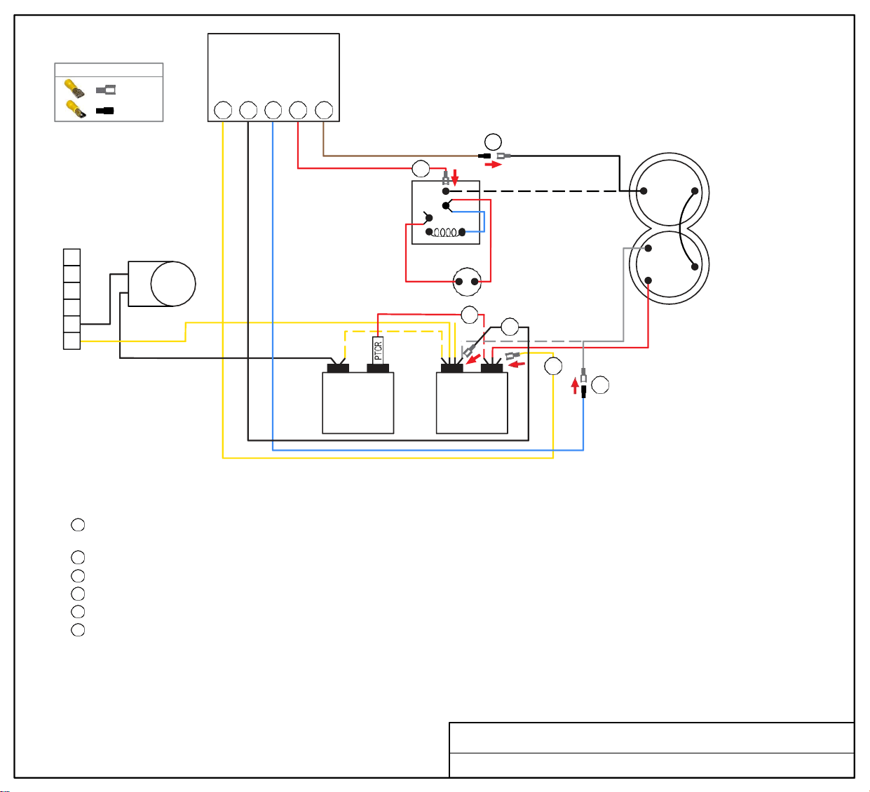
Soft
Start
WIRE CONNECTOR GUIDE
FEMALE
MALE
3 2 1 6 5
6
PRESSURE
2
SWITCH
RELAY
5
7
5
BLACK
COMPRESSOR
6
REVERSING
VALVE
5
4
3
2
1
START
CAPACITOR
4
2
3
C HERM
RUN
CAPACITOR
WHITE
1
R
C
S
RED
TURN ALL POWER OFF BEFORE STARTING INSTALLATION.
Route all SoftStart wires into the electrical box. Then crimp Connectors onto all SoftStart wires as indicated in drawing.
Step 1
Step 2
Step 3
Step 4
Step 5
Step 6
Follow White Compressor Wire from Compressor to Run Capacitor “C” terminal. Disconnect from “C” terminal and connect it to Blue
SoftStart wire. Tape connection with electrical tape.
Connect Black SoftStart wire to the terminal that the White Compressor Wire was on.
Connect Yellow SoftStart wire on terminal next to Red Compressor Wire on HERM terminal of Run Capacitor.
IF there is a second Red wire next to the Red Compressor wire, disconnect it, seal end with electrical tape and drop it.
Follow Black Compressor Wire to Pressure Switch Relay. Disconnect it and connect to Brown SoftStart wire. Tape connection.
Connect Red SoftStart wire onto the terminal that the Black Compressor Wire was on.
Secure all wires. Tape connections with electrical tape.
Turn Power and A/C Breaker on. Turn A/C to Auto Cool setting and set the thermostat to 55ºF.
Look at SoftStart LED lights. Green light should be “on”. Green light means the Compressor is running (there may be a full 3-minute delay before
Green light comes on). IF there is no Green light after 4 minutes, call SoftStart Tech Support for assistance.
After establishing Green light operation, re-install all A/C covers.
Turn A/C on, set near to outdoor temperature and run for 30 minutes.
After 30 minutes, operate A/C normally.
Wiring Diagram for Coleman Mach 1976-742 (11-20)
YELLOW
FEMALE
BLACK
FEMALE
BLUE
MALE
RED
FEMALE
BROWN
MALE
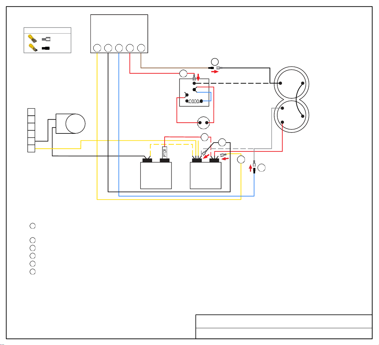
Soft
Start
WIRE CONNECTOR GUIDE
FEMALE
MALE
3 2 1 6 5
6
PRESSURE
2
SWITCH
RELAY
5
7
5
BLACK
COMPRESSOR
6
REVERSING
VALVE
5
4
3
2
1
START
CAPACITOR
4
2
3
C HERM
RUN
CAPACITOR
WHITE
1
R
C
S
RED
TURN ALL POWER OFF BEFORE STARTING INSTALLATION.
Route all SoftStart wires into the electrical box. Then crimp Connectors onto all SoftStart wires as indicated in drawing.
Step 1
Step 2
Step 3
Step 4
Step 5
Step 6
Follow White Compressor Wire from Compressor to Run Capacitor “C” terminal. Disconnect from “C” terminal and connect it to Blue
SoftStart wire. Tape connection with electrical tape.
Connect Black SoftStart wire to the terminal that the White Compressor Wire was on.
Connect Yellow SoftStart wire on terminal next to Red Compressor Wire on HERM terminal of Run Capacitor.
IF there is a second Red wire next to the Red Compressor wire, disconnect it, seal end with electrical tape and drop it.
Follow Black Compressor Wire to Pressure Switch Relay. Disconnect it and connect to Brown SoftStart wire. Tape connection.
Connect Red SoftStart wire onto the terminal that the Black Compressor Wire was on.
Secure all wires. Tape connections with electrical tape.
Turn Power and A/C Breaker on. Turn A/C to Auto Cool setting and set the thermostat to 55ºF.
Look at SoftStart LED lights. Green light should be “on”. Green light means the Compressor is running (there may be a full 3-minute delay before
Green light comes on). IF there is no Green light after 4 minutes, call SoftStart Tech Support for assistance.
After establishing Green light operation, re-install all A/C covers.
Turn A/C on, set near to outdoor temperature and run for 30 minutes.
After 30 minutes, operate A/C normally.
Wiring Diagram for Coleman Mach 1976-743 (02-18)
YELLOW
FEMALE
BLACK
FEMALE
BLUE
MALE
RED
FEMALE
BROWN
MALE
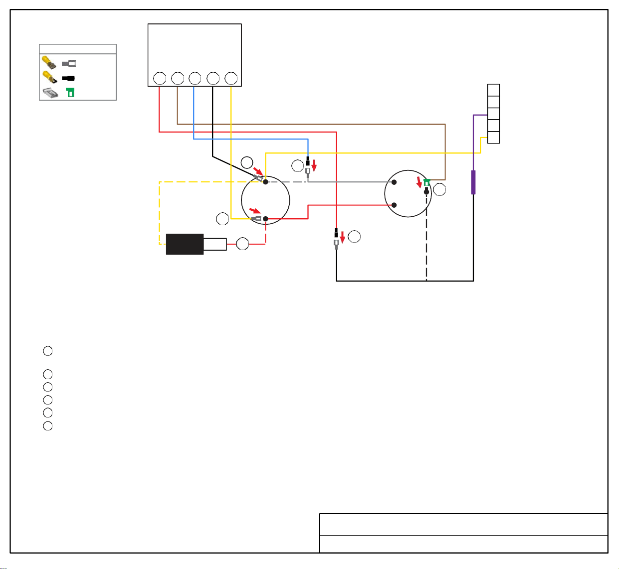
Soft
Start
5 6 1 2 3
5
4
3
2
1
3
PTCR
2
1
C
RUN
CAPACITOR
HERM
4
WHITE
R
COMPRESSOR
C
6
S
RED
5
START
CAPACITOR
TURN ALL POWER OFF BEFORE STARTING INSTALLATION.
Route Black, Yellow and Blue SoftStart wires into the electrical box. Then crimp Connectors onto SoftStart wires as indicated in drawing.
Route Brown and Red SoftStart wires to the top of the Compressor. Then attach Connectors as indicated in drawing.
Step
1
Step
2
Step
3
Step
4
Step
5
Step
6
Follow White Compressor wire from Compressor to Run Capacitor. Disconnect from terminal and connect it to Blue SoftStart wire. Tape
connection with electrical tape.
Connect Black SoftStart wire to the terminal that the White Compressor wire was on.
Connect Yellow SoftStart wire on terminal next to Red Compressor wire on HERM side of Run Capacitor.
IF there is a second Red wire next to Red Compressor wire on HERM side of Run Capacitor, disconnect it, seal end with tape and drop it.
Remove the Compressor Cap. Disconnect Black wire and connect to Red SoftStart wire. Tape connection.
Connect Brown SoftStart wire onto the terminal that the Black Compressor wire was on. Route Brown wire over to and out with Red and
White Compressor wires. Replace cap.
Secure all wires. Tape connections with electrical tape.
Turn Power and A/C Breaker on. Turn A/C to Auto Cool setting and set the thermostat to 55ºF.
Look at SoftStart LED lights. Green light should be “on”. Green light means the Compressor is running (there may be a full 3-minute delay before
Green light comes on). IF there is no Green light after 4 minutes, call SoftStart Tech Support for assistance.
After establishing Green light operation, re-install all A/C covers.
Turn A/C on, set near to outdoor temperature and run for 30 minutes.
After 30 minutes, operate A/C normally.
Wiring Diagram for Coleman Mach 1976-760 (03-20) NCF
FEMALE
MALE
FEMALE FLAG
WIRE CONNECTOR GUIDE
RED
BLACK
MALE
BROWN
FEMALE
FLAG
BLUE
MALE
BLACK
FEMALE
YELLOW
FEMALE
PURPLE
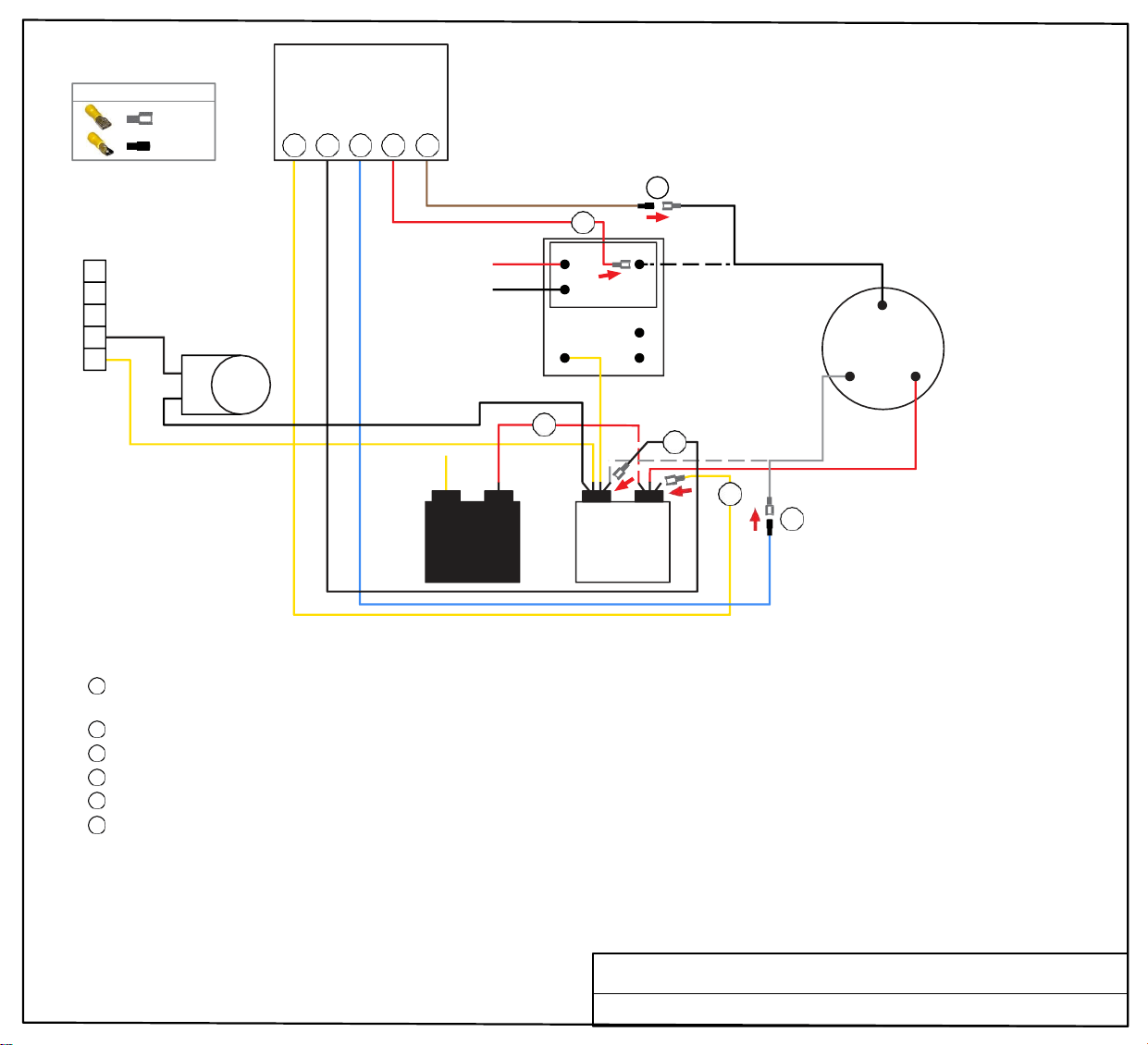
Soft
Start
WIRE CONNECTOR GUIDE
FEMALE
MALE
3 2 1 6 5
5
4
3
2
REVERSING
VALVE
1
5
6
N
C
N
O
COM
OUTDOOR
TEMP
RELAY
BOARD
BLACK
C
R S
COMPRESSOR
4
2
WHITE
START
CAPACITOR
3
C HERM
1
RUN
CAPACITOR
RED
TURN ALL POWER OFF BEFORE STARTING INSTALLATION.
Route all SoftStart wires into the electrical box. Then crimp Connectors onto all SoftStart wires as indicated in drawing.
Step
1
Follow White Compressor Wire from Compressor to Run Capacitor “C” terminal. Disconnect from “C” terminal and connect it to Blue
SoftStart wire. Tape connection with electrical tape.
Step 2
Step 3
Step
4
Step 5
Step
6
Connect Black SoftStart wire to the terminal that the White Compressor Wire was on.
Connect Yellow SoftStart wire on terminal next to Red Compressor Wire on HERM terminal of Run Capacitor.
IF there is a Black Capacitor with second Red wire next to the Red Compressor wire, disconnect it, seal end with tape and drop it.
Follow Black Compressor Wire to Outdoor Temperature Relay Board. Disconnect it and connect to Brown SoftStart wire. Tape connection.
Connect Red SoftStart wire onto the terminal that the Black Compressor Wire was on.
Secure all wires. Tape connections with electrical tape.
Turn Power and A/C Breaker on. Turn A/C to Auto Cool setting and set the thermostat to 55ºF.
Look at SoftStart LED lights. Green light should be “on”. Green light means the Compressor is running (there may be a full 3-minute delay before
Green light comes on). IF there is no Green light after 4 minutes, call SoftStart Tech Support for assistance.
After establishing Green light operation, re-install all A/C covers.
Turn A/C on, set near to outdoor temperature and run for 30 minutes.
After 30 minutes, operate A/C normally.
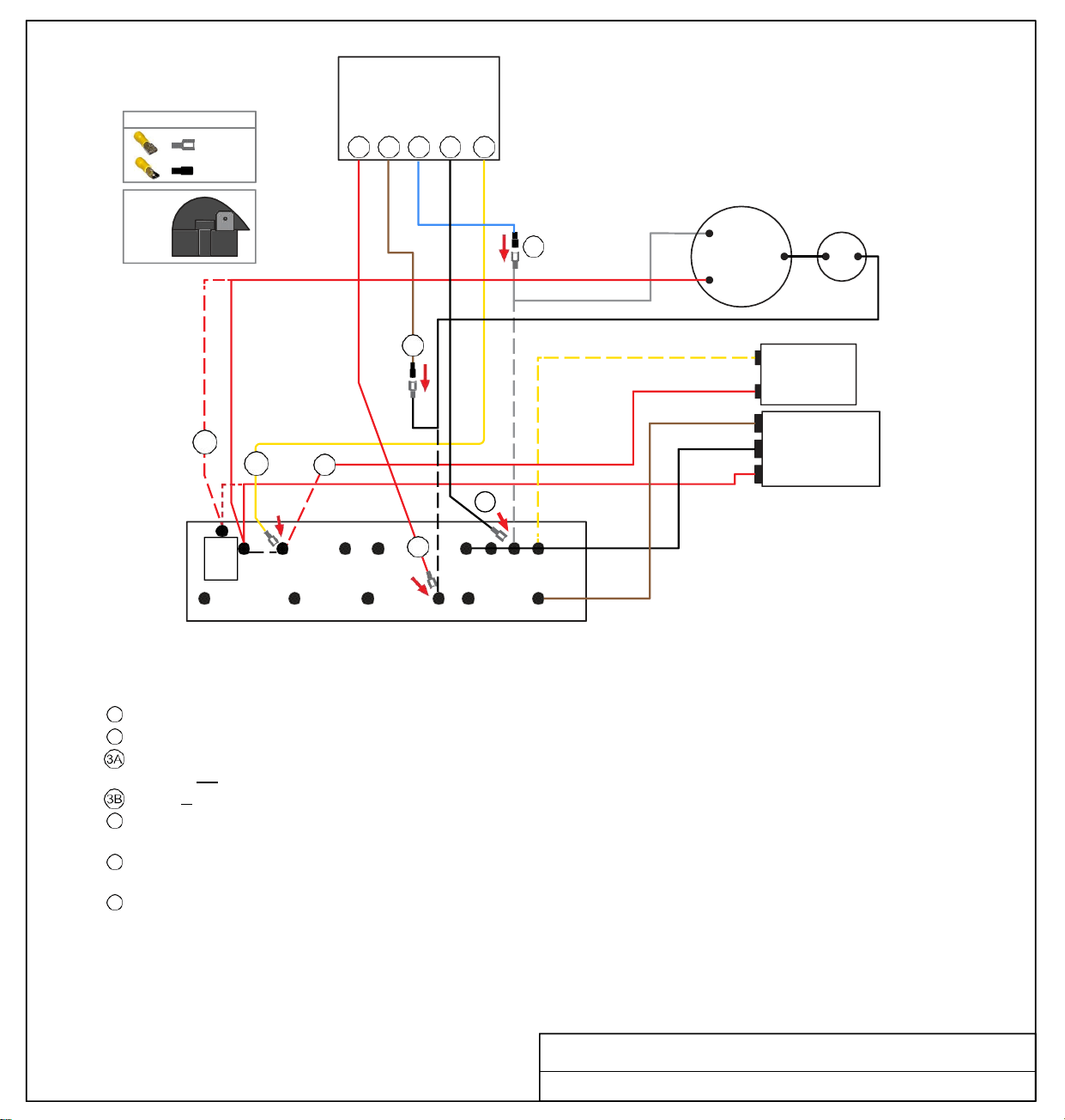
Wiring Diagram for Coleman Mach 1976-761 (02-20)
YELLOW
FEMALE
BLACK
FEMALE
BLUE
MALE
RED
FEMALE
BROWN
MALE
FEMALE
MALE
WIRE CONNECTOR GUIDE
6 5 1 2 3
Soft
Start
COMPRESSOR
RED
WHITE
R
1
C
S
BLACK
5
YELLOW
RED
(optional)
3B
3A
4
BROWN
BLACK
RED
PTCR
WHT
PTCR
BLK
RED
BLU
2
6
YEL
PUR BWN
TERMINAL
BOARD
TURN ALL POWER OFF BEFORE STARTING INSTALLATION.
NOTE: There are two options for Step 3, depending on your existing connections. Read both options carefully before proceeding.
Route ALL SoftStart wires into the electrical box. Then crimp Connectors onto all SoftStart wires as indicated in drawing.
Step 1 Follow White Compressor wire to Terminal Board. Disconnect from Terminal Board and connect to Blue SoftStart wire.
Step
2
Connect Black SoftStart wire to the terminal on the Terminal Board that the White Compressor Wire was on.
Step Connect Yellow SoftStart wire on terminal next to double Red wires (where PTCR is stamped on Terminal Board).
If there is not a black PTCR (looks like a black snail - see illustration above), skip Step 4 completely.
Step If there is a black PTCR, disconnect the double Red wires and connect them to PTCR terminal (stamped on Terminal Board).
Step 4
Step
5
Step
6
If there is a black PTCR, disconnect the single Red wire on terminal next to PTCR and seal end with tape. Connect Yellow SoftStart
wire that the single Red wire was on.
Disconnect Black Compressor Wire from Terminal Board. Connect Black Compressor Wire to Brown SoftStart wire and tape
connection with electrical tape.
Connect Red SoftStart wire to the terminal that the Black Compressor Wire was on.
Secure all wires. Tape connections with electrical tape.
Turn Power and A/C Breaker on. Turn A/C to Auto Cool setting and set the thermostat to 55ºF.
Look at SoftStart LED lights. Green light should be “on”. Green light means the Compressor is running (there may be a full 3-minute delay
before Green light comes on). IF there is no Green light after 4 minutes, call SoftStart Tech Support for assistance.
After establishing Green light operation, re-install all A/C covers.
Turn A/C on, set near to outdoor temperature and run for 30
minutes. After 30 minutes, operate A/C normally.
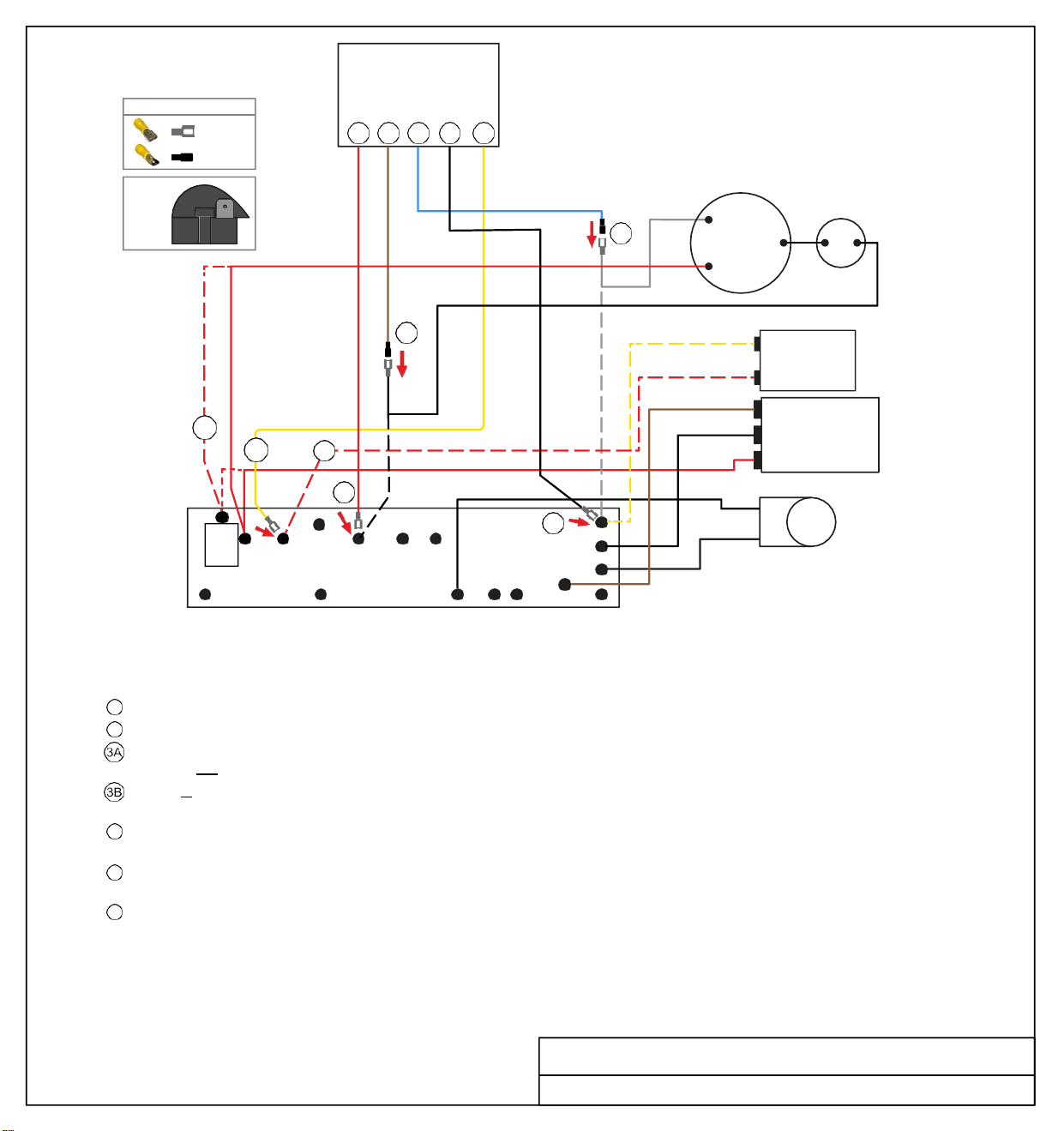
Wiring Diagram for Coleman Mach 1976-762 (03-20) TB
FAN
C
RUN
CAPACITOR
HERM
PTCR
(black
snail)
START
CAPACITOR
FEMALE
RED
MALE
BROWN
MALE
BLUE
FEMALE
BLACK
FEMALE
YELLOW
Soft
Start
WIRE CONNECTOR GUIDE
FEMALE
MALE
6 5 1 2 3
COMPRESSOR
RED
WHITE
R
1
C
S
BLACK
5
YELLOW
RED
START
CAPACITOR
(optional - applies to
Steps 3B and 4)
3B
3A
PTCR
4
6
WHT
BROWN
BLACK
RED
BLACK
2
BLACK
FAN
C
HERM
RUN
CAPACITOR
TERMINAL
BOARD
WHT
PTCR FREEZE
ORG
BLK
RED
BLU
PUR
BWN
REVERSING
VALVE
TURN ALL POWER OFF BEFORE STARTING INSTALLATION.
NOTE: There are two options for Step 3, depending on your existing connections. Read both options carefully before proceeding.
Route ALL SoftStart wires into the electrical box. Then crimp Connectors onto all SoftStart wires as indicated in drawing.
Step 1 Follow White Compressor wire to Terminal Board. Disconnect from Terminal Board and connect to Blue SoftStart wire.
Step 2 Connect Black SoftStart wire to the terminal on the Terminal Board that the White Compressor Wire was on.
Step Connect Yellow SoftStart wire on terminal next to double Red wires (where PTCR is stamped on Terminal Board).
If there is not a black PTCR (looks like a black snail - see illustration above), skip Step 4 completely.
Step If there is a black PTCR, disconnect the PTCR from the Terminal Board, then disconnect the double Red wires and connect them to
the terminal that the PTCR was on.
Step
4
Step 5
Step
6
Disconnect the single Red wire on terminal next to PTCR and seal end with tape. Connect Yellow SoftStart wire that the single Red
wire was on.
Disconnect Black Compressor Wire from Freeze connection on Terminal Board. Connect Black Compressor Wire to Brown
SoftStart wire and tape connection with electrical tape.
Connect Red SoftStart wire to the terminal that the Black Compressor Wire was on.
Secure all wires. Tape connections with electrical tape.
Turn Power and A/C Breaker on. Turn A/C to Auto Cool setting and set the thermostat to 55ºF.
Look at SoftStart LED lights. Green light should be “on”. Green light means the Compressor is running (there may be a full 3-minute delay
before Green light comes on). IF there is no Green light after 4 minutes, call SoftStart Tech Support for assistance.
After establishing Green light operation, re-install all A/C covers.
Turn A/C on, set near to outdoor temperature and run for 30
minutes. After 30 minutes, operate A/C normally.
Wiring Diagram for Coleman Mach 1976-763 (03-20) TB
PTCR
(black
snail)
FEMALE
RED
BROWN
MALE
BLUE
MALE
FEMALE
BLACK
FEMALE
YELLOW
YEL
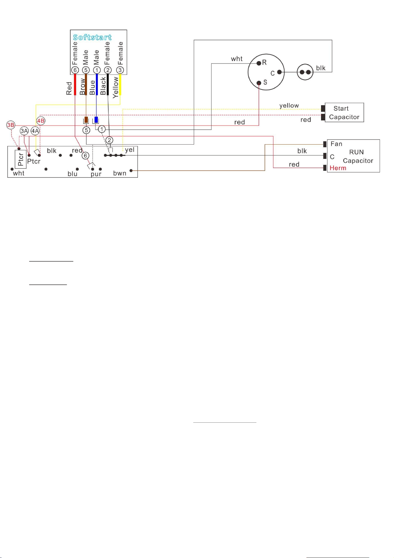
Coleman Mach 1976-764
Coleman Mach 1976-764(03-20)
COLEMAN
1976-
764
NOTE: Route All Softstart wires into the electrical box, then crimp disconnects as shown in
softstart
box at top
Step 1) Follow the White Compressor wire to Run Capacitor “C” Terminal. Disconnect and connect it
to the Blue SoftstartRV wire.
Step 2) Connect the Black SoftstartRV wire to the terminal the White wire was on.
Step 3) Follow the Red compressor wire from the compressor to the “HERM” terminal. At that point
you will notice that the Red Compressor is on a Double Connector with a second Red wire.
DO
NOT DISCONNECT Eit her of the RED WIRES
. Connect the Yellow SoftstartRV wire on the
Terminal next to the Red compressor wire if it is available (see next step).
Step 4) IF you see a 2nd Red wire next to the Connector with the double Red wires,
DISCONNECT it,
tape the end and drop it. Then connect the Yellow SoftstartRV wire on the Terminal where you
pulled o the second Red wire.

Coleman Mach 1976-764
NOTE: IF you see a PTCR (see picture above), P ull it o the Terminal and remove the connector with
the double red wires. Then put the connector with the double Red wires back on the Terminal
where the PTCR was. If you then see another Red wire next to it, DISCONNECT it, tape the end and
drop it. Then Connect the Yellow SoftstartRV wire on the Terminal where you just pulled o the
Red wire.
Step 5) Follow the Black Compressor wire to the “PUR” Terminal (Purple wire will be directly
across
from it), Disconnect the Black wire and connect it to the Brown SoftstartRV wire.
Step 6) Connect the Red SoftstartRV wire on the Terminal that the Black compressor wire was on.
Before turning the power back on, secure wires to prevent the fan from pulling them in.
Turn the
Power and A/C breaker on, Turn the Fan on High until you hear it running, then Turn the A/C to
Auto Cool and set the Thermostat to 55 degrees.
Look at the SoftstartRV for a Green light (There may be a full 3 min delay before the
Green light
comes on).
After you see the Green Light, Turn the power o , tidy up your wires and replace all
covers. Then
turn the A/C back on and allow it to run for 30 min at about 2 degrees below the outside
temperature which should allow it to cycle a few times.
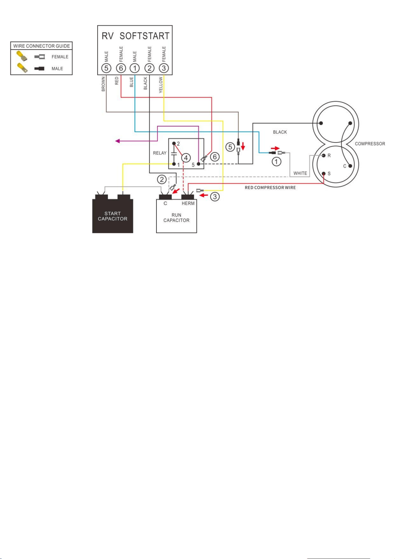
Coleman Mach 1976A061
Wiring Diagram for Coleman Mach 1976A061(10-91)
Instructions
TURN ALL POWER OFF BEFORE STARTING INSTALLATION.
Route ALL SoftStart wires into the electrical box. Then crimp Connectors onto all SoftStart wires as
indicated in drawing.

Coleman Mach 1976A061
Step 1. Follow White Compressor wire from Compressor to Run Capacitor “C” terminal. Disconnect
from “C” terminal and connect it to Blue SoftStart wire. Seal connection with electrical tape.
Step 2. Connect Black SoftStart wire to the terminal that the White Compressor wire was on.
Step 3. Connect Yellow SoftStart wire on terminal next to Red Compressor wire on HERM side of Run
Capacitor.
Step 4. If there is another Red wire next to the Red Compressor wire, disconnect it from Run
Capacitor. Seal end with electrical tape and drop it.
Step 5. Follow Black Compressor wire to Relay. Disconnect Black wire from Relay and connect to
Brown SoftStart wire. Tape connection.
Step 6. Connect Red SoftStart wire onto the Relay terminal that the Black Compressor wire was on.
Secure all wires. Seal connections with electrical tape.
Turn Power and A/C Breaker on. Turn A/C to Auto Cool setting and set the thermostat to 55ºF.
Look at SoftStart LED lights. Green light should be “on”. Green light means the Compressor is
running (there may be a full 3-minute delay before Green light comes on). IF there is no Green light
after 4 minutes, call SoftStart Tech Support for assistance.
After establishing Green light operation, re-install all A/C covers. Turn A/C on, set near to outdoor
temperature and run for 30 minutes. After 30 minutes, operate A/C normally.
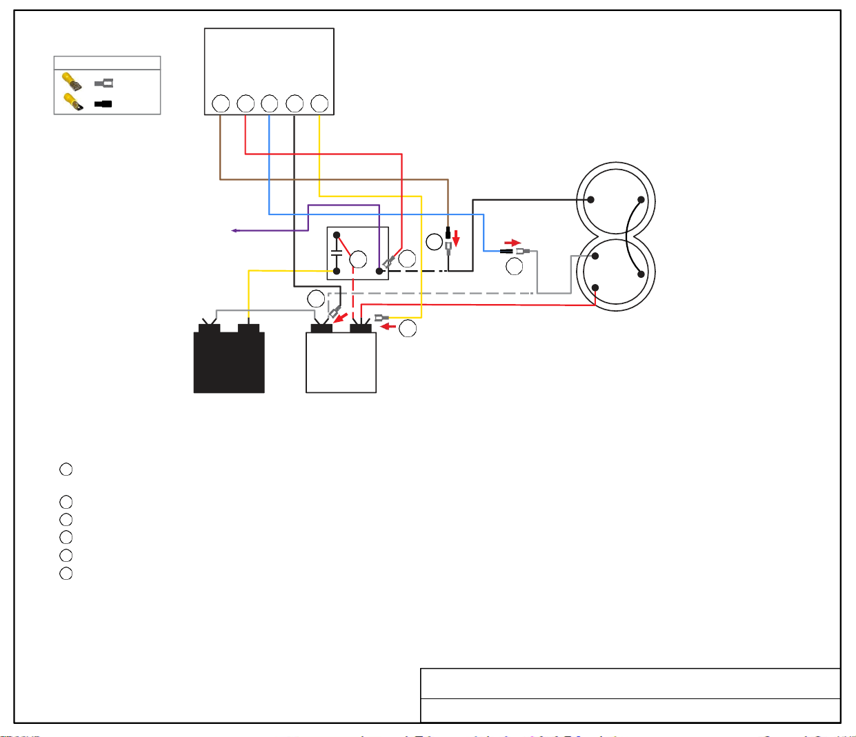
FEMALE
MALE
WIRE CONNECTOR GUIDE
5 6 1 2 3
Soft
Start
2
5
RELAY
4
6
BLACK
COMPRESSOR
R
1 5
1
2
C
WHITE
S
START
CAPACITOR
3
C HERM
RUN
CAPACITOR
RED COMPRESSOR WIRE
TURN ALL POWER OFF BEFORE STARTING INSTALLATION.
Route ALL SoftStart wires into the electrical box. Then crimp Connectors onto all SoftStart wires as indicated in drawing.
Step
1
Step
2
Step
3
Step
4
Step
5
Step
6
Follow White Compressor wire from Compressor to Run Capacitor “C” terminal. Disconnect from “C” terminal and connect it to Blue
SoftStart wire. Seal connection with electrical tape.
Connect Black SoftStart wire to the terminal that the White Compressor wire was on.
Connect Yellow SoftStart wire on terminal next to Red Compressor wire on HERM side of Run Capacitor.
If there is another Red wire next to the Red Compressor wire, disconnect it from Run Capacitor. Seal end with electrical tape and drop it.
Follow Black Compressor wire to Relay. Disconnect Black wire from Relay and connect to Brown SoftStart wire. Tape connection.
Connect Red SoftStart wire onto the Relay terminal that the Black Compressor wire was on.
Secure all wires. Seal connections with electrical tape.
Turn Power and A/C Breaker on. Turn A/C to Auto Cool setting and set the thermostat to 55ºF.
Look at SoftStart LED lights. Green light should be “on”. Green light means the Compressor is running (there may be a full 3-minute delay before
Green light comes on). IF there is no Green light after 4 minutes, call SoftStart Tech Support for assistance.
After establishing Green light operation, re-install all A/C covers.
Turn A/C on, set near to outdoor temperature and run for 30 minutes.
After 30 minutes, operate A/C normally.
Wiring Diagram for Coleman Mach 1976A096 (5-90) Relay
BROWN
MALE
RED
FEMALE
BLUE
MALE
BLACK
FEMALE
YELLOW
FEMALE
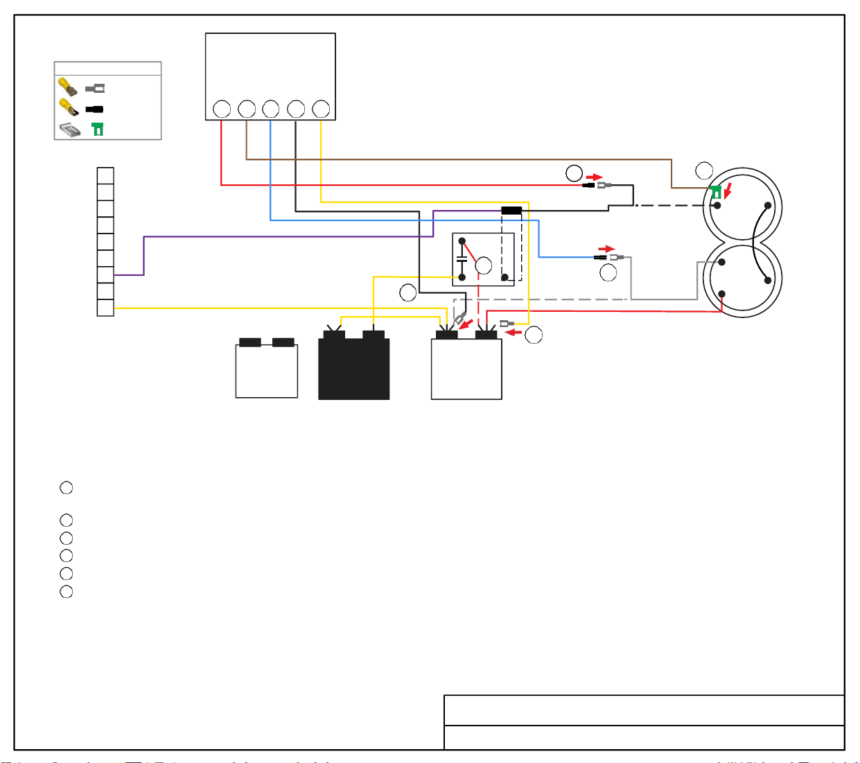
Soft
Start
WIRE CONNECTOR GUIDE
FEMALE
MALE
FEMA LE FLAG
5 6 1 2 3
9
8
7
6
5 2
4
RELAY
4
5
6
BLACK
R
COMPRESSOR
3
1 5
2
2
1
1
C
WHITE
S
START
CAPACITOR
3
C HERM
RUN
CAPACITOR
RED COMPRESSOR WIRE
TURN ALL POWER OFF BEFORE STARTING INSTALLATION.
Route Black, Yellow and Blue SoftStart wires into the electrical box. Then crimp Connectors onto SoftStart wires as indicated in drawing.
Route Brown and Red SoftStart wires to the top of the Compressor. Then attach Connectors as indicated in drawing.
Step 1
Step 2
Step 3
Step
4
Step 5
Step 6
Follow White Compressor wire from Compressor to Run Capacitor “C” terminal. Disconnect from “C” terminal and connect it to Blue
SoftStart wire. Tape connection with electrical tape.
Connect Black SoftStart wire to the terminal that the White Compressor wire was on.
Connect Yellow SoftStart wire on terminal next to Red Compressor wire on HERM side of Run Capacitor.
Disconnect the Red wire from the Run Capacitor that goes to the Start Relay. Seal end with electrical tape and drop it.
Remove the Compressor Cap. Disconnect Black wire and connect to Red SoftStart wire. Tape connection. (Wires do not go back under cap.)
Connect Brown SoftStart wire onto the terminal that the Black Compressor wire was on. Route Brown wire over to and out with Red and
White Compressor wires. Replace cap. (The Overload can be moved to place the cap back on it.)
Secure all wires. Seal connections with electrical tape.
Turn Power and A/C Breaker on. Turn A/C to Auto Cool setting and set the thermostat to 55ºF.
Look at SoftStart LED lights. Green light should be “on”. Green light means the Compressor is running (there may be a full 3-minute delay before
Green light comes on). IF there is no Green light after 4 minutes, call SoftStart Tech Support for assistance.
After establishing Green light operation, re-install all A/C covers.
Turn A/C on, set near to outdoor temperature and run for 30 minutes.
After 30 minutes, operate A/C normally.
Wiring Diagram for Coleman Mach 1976A136 (5-92)
RED
FAN
CAPACITOR
MALE
BROWN
FEMALE
FLAG
BLUE
MALE
BLACK
FEMALE
YELLOW
FEMALE
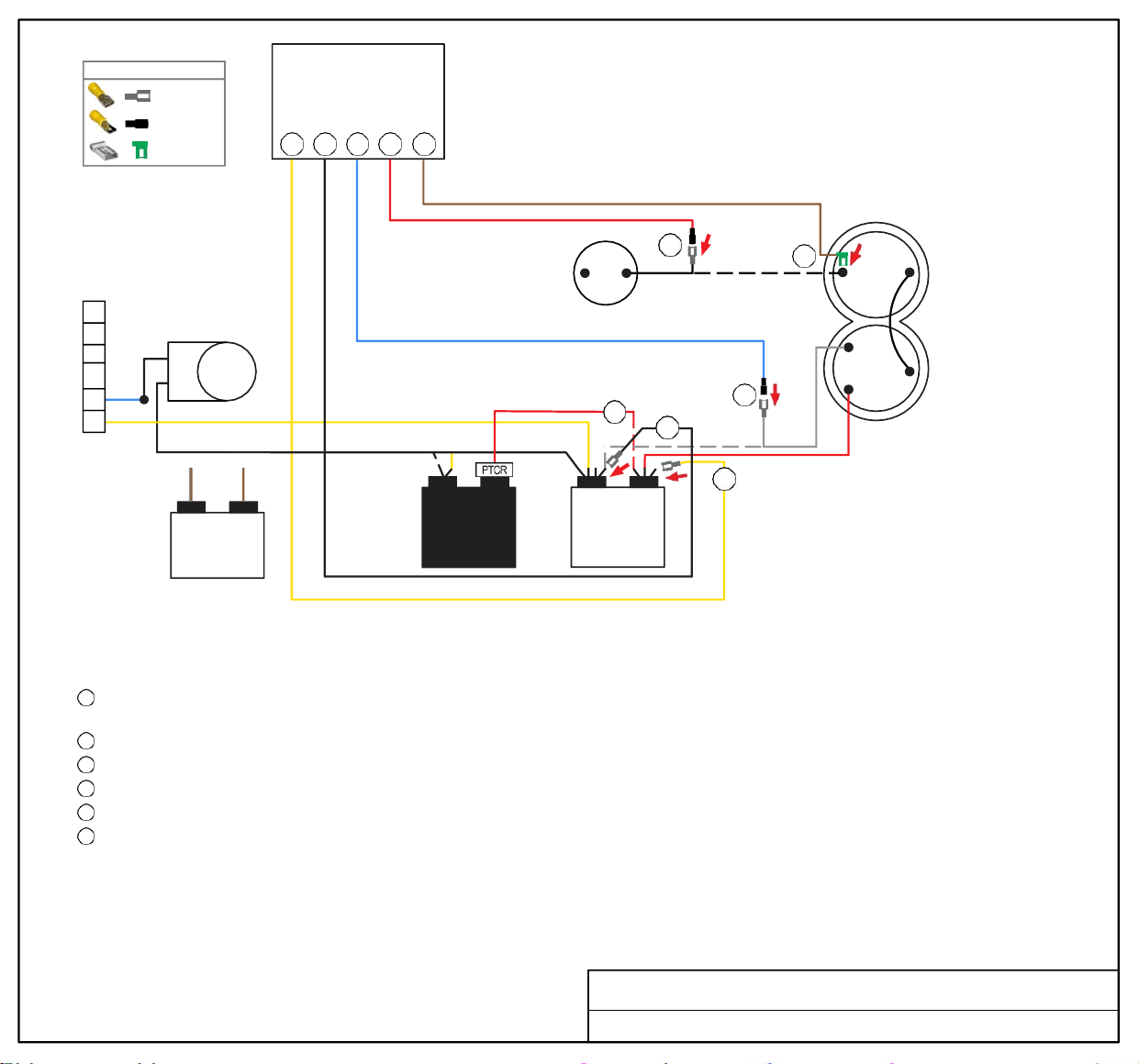
REVERSING
VALVE
FREEZE
SWITCH
5
BLACK
4
2
6
1
WHITE
3
R
S
RED
COMPRESSOR
C
FAN
CAPACITOR
START
CAPACITOR
TURN ALL POWER OFF BEFORE STARTING INSTALLATION.
Route Black, Blue and Yellow SoftStart wires into the electrical box. Route Brown and Red SoftStart wires to the top of the Compressor.
Then crimp Connectors onto all SoftStart wires as indicated in drawing.
Step 1
Step 2
Step 3
Step 4
Step 5
Step 6
Follow White Compressor wire from Compressor to Run Capacitor “C” terminal (inside the electrical box). Disconnect from “C” terminal
and connect it to Blue SoftStart wire. Seal connection with electrical tape.
Connect Black SoftStart wire to the terminal that the White Compressor wire was on.
Connect Yellow SoftStart wire on terminal next to Red Compressor wire on HERM terminal of Run Capacitor.
IF there is a second Red wire next to the Red Compressor wire, disconnect it, seal end with electrical tape and drop it.
Remove the Compressor Cap. Disconnect Black wire and connect to Red SoftStart wire. Tape connection. Do not put wires back under cap.
Connect Brown SoftStart wire onto the terminal that the Black Compressor wire was on. Route Brown SoftStart wire out with
Red and White Compressor wires. Replace cap.
Secure all wires. Tape connections with electrical tape.
Turn Power and A/C Breaker on. Turn A/C to Auto Cool setting and set the thermostat to 55ºF.
Look at SoftStart LED lights. Green light should be “on”. Green light means the Compressor is running (there may be a full 3-minute delay before
Green light comes on). IF there is no Green light after 4 minutes, call SoftStart Tech Support for assistance.
After establishing Green light operation, re-install all A/C covers.
Turn A/C on, set near to outdoor temperature and run for 30 minutes.
After 30 minutes, operate A/C normally.
Wiring Diagram for Coleman Mach 1976A363 (05-02)
1
2
3
4
5
6
FEMALE
MALE
FEMALE FLAG
WIRE CONNECTOR GUIDE
3 2 1 5 6
C HERM
RUN
CAPACITOR
BRN/
WHT
Soft
Start
YELLOW
BRN
FEMALE
BLACK
FEMALE
BLUE
RED
MALE
MALE
BROWN
FEMALE
FLAG
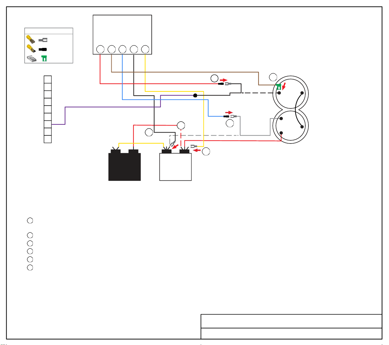
Soft
Start
WIRE CONNECTOR GUIDE
FEMALE
MALE
FEMA LE FLAG
5 6 1 2 3
9
8
7
6
5
4
3
2
2
1
START
CAPACITOR
4
C HERM
RUN
CAPACITOR
5
6
BLACK
R
1
WHITE
S
RED COMPRESSOR WIRE
3
COMPRESSOR
C
TURN ALL POWER OFF BEFORE STARTING INSTALLATION.
Route Black, Blue and Yellow SoftStart wires into the electrical box. Route Brown and Red SoftStart wires to the top of the Compressor.
Then crimp Connectors onto all SoftStart wires as indicated in drawing.
Step
1
Step
2
Step
3
Step
4
Step
5
Step
6
Follow White Compressor wire from Compressor to Run Capacitor “C” terminal. Disconnect from “C” terminal and connect it to Blue
SoftStart wire. Tape connection with electrical tape.
Connect Black SoftStart wire to the terminal that the White Compressor wire was on.
Connect Yellow SoftStart wire on terminal next to Red Compressor wire on HERM side of Run Capacitor.
IF there is a second Red wire next to the Red Compressor wire, disconnect it, seal end with electrical tape and drop it.
Remove the Compressor Cap. Disconnect Black wire and connect to Red SoftStart wire. Tape connection. (Wires do not go back under cap.)
Connect Brown SoftStart wire onto the terminal that the Black Compressor wire was on. Route Brown wire over to and out with Red and
White Compressor wires. Replace cap.
Secure all wires. Seal connections with electrical tape.
Turn Power and A/C Breaker on. Turn A/C to Auto Cool setting and set the thermostat to 55ºF.
Look at SoftStart LED lights. Green light should be “on”. Green light means the Compressor is running (there may be a full 3-minute delay before
Green light comes on). IF there is no Green light after 4 minutes, call SoftStart Tech Support for assistance.
After establishing Green light operation, re-install all A/C covers.
Turn A/C on, set near to outdoor temperature and run for 30 minutes.
After 30 minutes, operate A/C normally.
Wiring Diagram for Coleman Mach 1976A364 (09-02)
RED
MALE
FEMALE
FLAG
BROWN
BLUE
MALE
BLACK
FEMALE
YELLOW
FEMALE
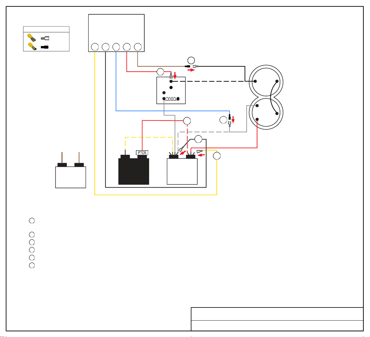
Soft
Start
3 2 1
6 5
6
PRESSURE
2
SWITCH
5
RELAY
7
5
BLACK
4
2
1
WHITE
COMPRESSOR
R
C
S
FAN
CAPACITOR
START
CAPACITOR
3
C HERM
RUN
CAPACITOR
RED
TURN ALL POWER OFF BEFORE STARTING INSTALLATION.
Route all SoftStart wires into the electrical box. Then crimp Connectors onto all SoftStart wires as indicated in drawing.
Step 1
Step 2
Step 3
Step 4
Step 5
Step 6
Follow White Compressor wire from Compressor to Run Capacitor “C” terminal. Disconnect from “C” terminal and connect it to
Blue SoftStart wire. Tape connection with electrical tape.
Connect Black SoftStart wire to the terminal that the White Compressor wire was on.
Connect Yellow SoftStart wire on terminal next to Red Compressor wire on HERM terminal of Run Capacitor.
IF there is a second Red wire next to the Red Compressor wire, disconnect it, seal end with electrical tape and drop it.
Follow Black Compressor wire to Pressure Switch Relay terminal. Disconnect it and connect to Brown SoftStart wire. Tape connection.
Connect Red SoftStart wire onto the terminal that the Black Compressor wire was on.
Secure all wires. Tape connections with electrical tape.
Turn Power and A/C Breaker on. Turn A/C to Auto Cool setting and set the thermostat to 55ºF.
Look at SoftStart LED lights. Green light should be “on”. Green light means the Compressor is running (there may be a full 3-minute delay before
Green light comes on). IF there is no Green light after 4 minutes, call SoftStart Tech Support for assistance.
After establishing Green light operation, re-install all A/C covers.
Turn A/C on, set near to outdoor temperature and run for 30 minutes.
After 30 minutes, operate A/C normally.
Wiring Diagram for Coleman Mach 1976A518 Relay
FEMALE
MALE
WIRE CONNECTOR GUIDE
BRN/
WHT
BRN
YELLOW
FEMALE
BLACK
FEMALE
BLUE
MALE
FEMALE
RED
MALE
BROWN
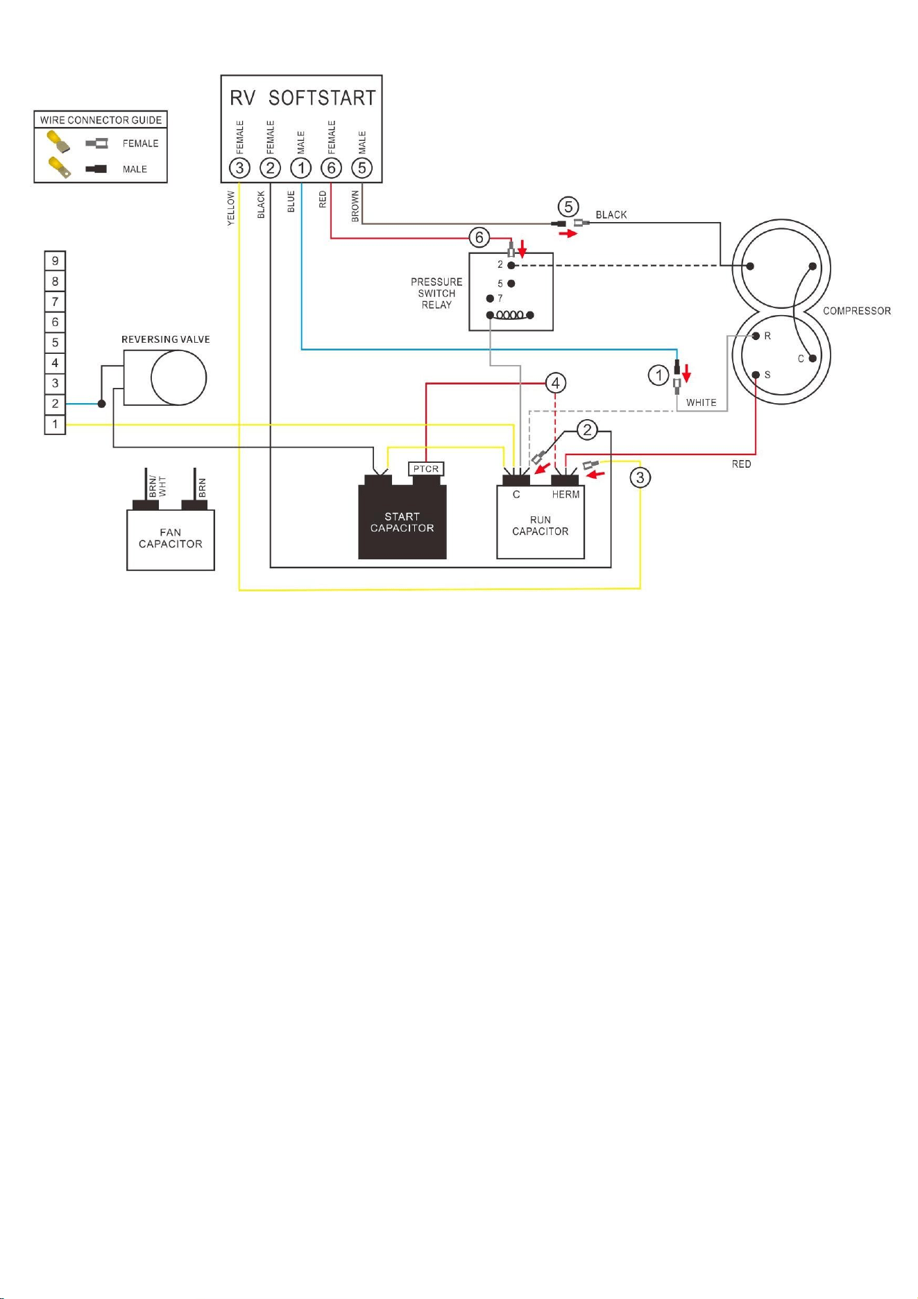
Coleman Mach 1976A519
Wiring Diagram for Coleman Mach 1976A519
Instructions
TURN ALL POWER OFF BEFORE STARTING INSTALLATION.
Route all SoftStart wires into the electrical box. Then crimp Connectors onto all SoftStart wires as
indicated in drawing.

Coleman Mach 1976A519
Step 1. Follow White Compressor wire from Compressor to Run Capacitor “C” terminal. Disconnect
from “C” terminal and connect it to Blue SoftStart wire. Tape connection with electrical tape.
Step 2. Connect Black SoftStart wire to the terminal that the White Compressor wire was on.
Step 3. Connect Yellow SoftStart wire on terminal next to Red Compressor wire on HERM terminal of
Run Capacitor.
Step 4. IF there is a second Red wire next to the Red Compressor wire, disconnect it, seal end with
electrical tape and drop it.
Step 5. Follow Black Compressor wire to Pressure Switch Relay terminal. Disconnect it and connect to
Brown SoftStart wire. Tape connection.
Step 6. Connect Red SoftStart wire onto the terminal that the Black Compressor wire was on.
Secure all wires. Tape connections with electrical tape.
Turn Power and A/C Breaker on. Turn A/C to Auto Cool setting and set the thermostat to 55ºF.
Look at SoftStart LED lights. Green light should be “on”. Green light means the Compressor is
running (there may be a full 3-minute delay before Green light comes on). IF there is no Green light
after 4 minutes, call SoftStart Tech Support for assistance.
After establishing Green light operation, re-install all A/C covers.
Turn A/C on, set near to outdoor temperature and run for 30 minutes. After 30 minutes, operate A/C
normally.
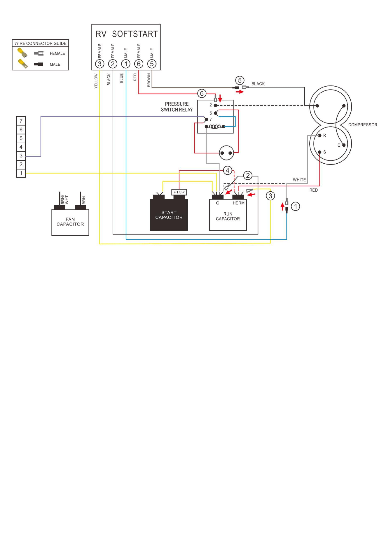
Coleman Mach 1976A536
Wiring Diagram for Coleman Mach 1976A536(12-09)
Relay
SoftStartRV Wiring Diagram for Coleman Mach
1976A536

Coleman Mach 1976A536
Route all SoftStart wires into the electrical box. Then crimp Connectors onto all
SoftStart wires as indicated in drawing.
Step 1. Follow White Compressor wire from Compressor to Run Capacitor “C”
terminal. Disconnect from “C” terminal and connect it to Blue SoftStart wire.
Tape connection with electrical tape.
Step 2. Connect Black SoftStart wire to the terminal that the White Compressor
wire was on.
Step 3. Connect Yellow SoftStart wire on terminal next to Red Compressor wire
on HERM terminal of Run Capacitor.
Step 4. IF there is a second Red wire next to the Red Compressor wire,
disconnect it, seal end with electrical tape and drop it.
Step 5. Follow Black Compressor wire to Pressure Switch Relay. Disconnect it
from the Relay and connect to Brown SoftStart wire. Tape connection.
Step 6. Connect Red SoftStart wire onto the terminal that the Black Compressor
wire was on.
Secure all wires. Tape connections with electrical tape.
Turn Power and A/C Breaker on. Turn A/C to Auto Cool setting and set the
thermostat to 55ºF.
Look at SoftStart LED lights. Green light should be “on”. Green light means the
Compressor is running (there may be a full 3-minute delay before Green light
comes on). IF there is no Green light after 4 minutes, call SoftStart Tech Support
for assistance.
After establishing Green light operation, re-install all A/C covers.
Turn A/C on, set near to outdoor temperature and run for 30 minutes. After 30
minutes, operate A/C normally.
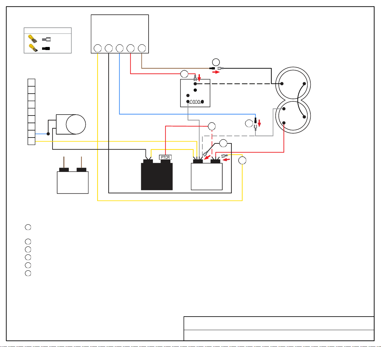
Soft
Start
WIRE CONNECTOR GUIDE
FEMALE
MALE
9
8
7
6
3 2 1 6 5
6
2
PRESSURE
5
SWITCH
7
RELAY
5
BLACK
COMPRESSOR
5
REVERSING
VALVE
4
3
2
1
R
C
4
1
S
WHITE
2
FAN
CAPACITOR
START
CAPACITOR
3
C HERM
RUN
CAPACITOR
RED
TURN ALL POWER OFF BEFORE STARTING INSTALLATION.
Route all SoftStart wires into the electrical box. Then crimp Connectors onto all SoftStart wires as indicated in drawing.
Step 1
Step 2
Step 3
Step 4
Step 5
Step 6
Follow White Compressor wire from Compressor to Run Capacitor “C” terminal. Disconnect from “C” terminal and connect it to
Blue SoftStart wire. Tape connection with electrical tape.
Connect Black SoftStart wire to the terminal that the White Compressor wire was on.
Connect Yellow SoftStart wire on terminal next to Red Compressor wire on HERM terminal of Run Capacitor.
IF there is a second Red wire next to the Red Compressor wire, disconnect it, seal end with electrical tape and drop it.
Follow Black Compressor wire to Pressure Switch Relay terminal. Disconnect it and connect to Brown SoftStart wire. Tape connection.
Connect Red SoftStart wire onto the terminal that the Black Compressor wire was on.
Secure all wires. Tape connections with electrical tape.
Turn Power and A/C Breaker on. Turn A/C to Auto Cool setting and set the thermostat to 55ºF.
Look at SoftStart LED lights. Green light should be “on”. Green light means the Compressor is running (there may be a full 3-minute delay before
Green light comes on). IF there is no Green light after 4 minutes, call SoftStart Tech Support for assistance.
After establishing Green light operation, re-install all A/C covers.
Turn A/C on, set near to outdoor temperature and run for 30 minutes.
After 30 minutes, operate A/C normally.
Wiring Diagram for Coleman Mach 1976A537 (12-09) Relay
BRN/
WHT
YELLOW
BRN
FEMALE
BLACK
FEMALE
BLUE
MALE
RED
FEMALE
BROWN
MALE
Soft
Start
FAN
MOTOR
BLACK COMPRESSOR WIRE
COMPRESSOR
6 5 1 2 3
WHITE
BLACK
WHITE
R
C
S
1
6
5
2
5
PRESSURE
7
SWITCH
RELAY
2
C HERM
RUN
CAPACITOR
RED
YELLOW
START
CAPACITOR
RED
4 3
PTCR
WHT
PTCR
BLK
ORG
RED
BLU
PUR
YEL
REVERSING
VALVE
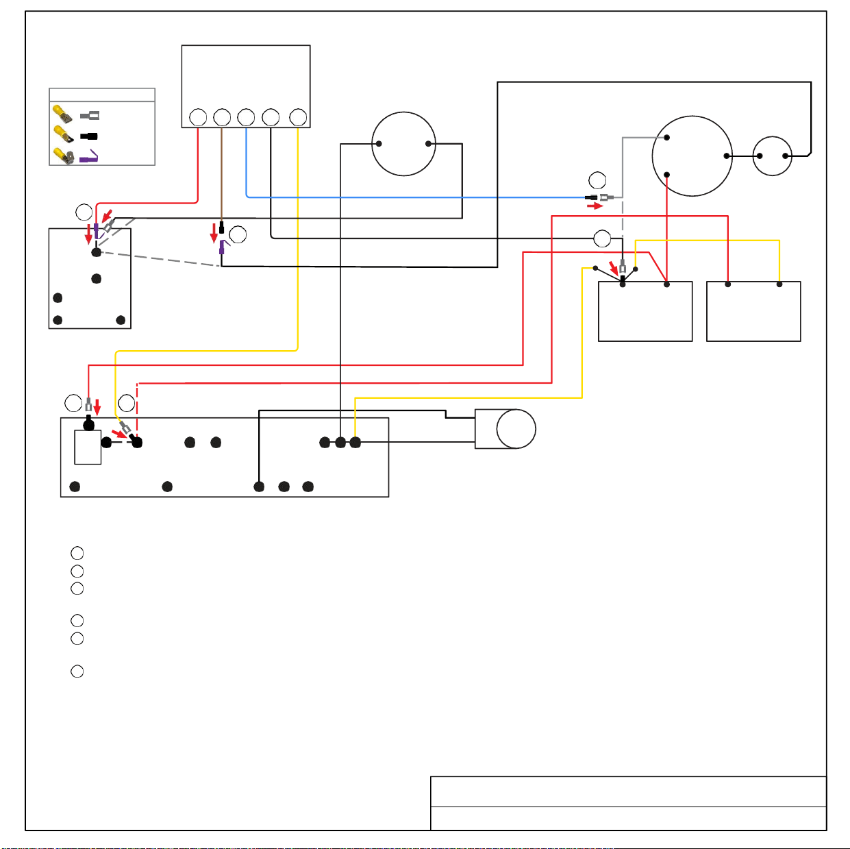
TURN ALL POWER OFF BEFORE STARTING INSTALLATION.
Route ALL SoftStart wires into the electrical box. Then crimp Connectors onto all SoftStart wires as indicated in drawing.
Step
1
Step 2
Step 3
Step 4
Step 5
Step 6
Follow White Compressor wire to Run Capacitor “C” terminal. Disconnect from Run Capacitor and connect to Blue SoftStart wire.
Connect Black SoftStart wire to the terminal on the Run Capacitor that the White Compressor wire was on.
Disconnect single Red wire next to PTCR (running from Start Capacitor) and tape end with electrical tape. Connect Yellow SoftStart
wire on terminal that the Red wire was on.
Disconnect PTCR. Disconnect Red wire from PTCR and connect Red wire on terminal that the PTCR was on.
Follow Black Compressor Wire to Pressure Switch Relay and disconnect it from Relay. Also, disconnect Black Fan wire from Black
Compressor wire. Connect Black Compressor wire to Brown SoftStart wire and tape connection with electrical tape.
Connect Red SoftStart wire to Pressure Switch Relay. Connect Black Fan wire to male terminal on Red SoftStart wire
(use piggyback connector).
Secure wires to prevent Fan from pulling wires in. Tape connections with electrical tape.
Turn Power and A/C Breaker on. Turn A/C to Auto Cool setting and set the thermostat to 55ºF.
Look at SoftStart LED lights. Green light should be “on”. Green light means the Compressor is running (there may be a full 3-minute delay
before Green light comes on). IF there is no Green light after 4 minutes, call SoftStart Tech Support for assistance.
After establishing Green light operation, re-install all A/C covers.
Turn A/C on, set near to outdoor temperature and run for 30
minutes. After 30 minutes, operate A/C normally.
Wiring Diagram for Coleman Mach 1976A603 (3-14) TB
FEMALE
MALE
PIGGYBACK
WIRE CONNECTOR GUIDE
RED
PIGGYBACK
BROWN
MALE
BLUE
MALE
BLACK
FEMALE
YELLOW
FEMALE
RED
Coleman Mach 1976A613
Wiring Diagram for Coleman Mach 1976A613
Instructions
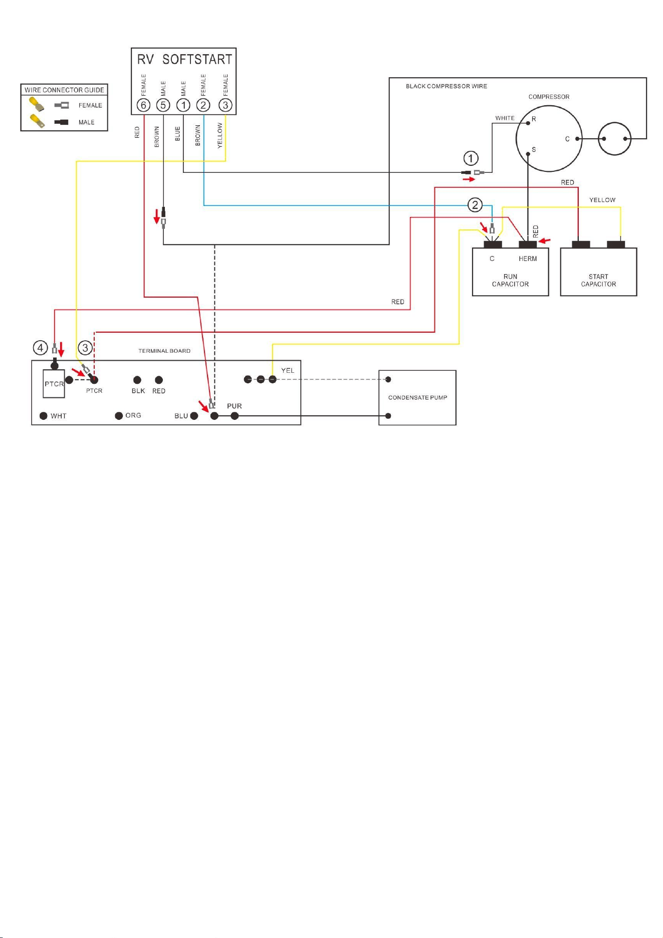
TURN ALL POWER OFF BEFORE STARTING INSTALLATION.

Coleman Mach 1976A613
Route ALL SoftStart wires into the electrical box. Then crimp Connectors onto all SoftStart wires as
indicated in drawing.
Step 1. Follow White Compressor wire to Run Capacitor. Disconnect from Run Capacitor and connect
to Blue SoftStart wire.
Step 2. Connect Black SoftStart wire to the terminal on the Run Capacitor that the White Compressor
wire was on.
Step 3. Disconnect single Red wire next to PTCR (running from Start Capacitor) and tape end with
electrical tape. Connect Yellow SoftStart wire on terminal that the Red wire was on.
Step 4. Disconnect PTCR. Disconnect Red wire from PTCR and reconnect Red wire onto terminal that
the PTCR was on.
Step 5. Follow Black Compressor wire to the terminal by PUR on the terminal board. Disconnect it,
then connect Black Compressor wire to Brown SoftStart wire and seal connection with electrical
tape.
Step 6. Connect Red SoftStart wire to the terminal that the Black Compressor wire was on.
Secure wires to prevent Fan from pulling wires in. Tape connections with electrical tape.
Turn Power and A/C Breaker on. Turn A/C to Auto Cool setting and set the thermostat to 55ºF.
Look at SoftStart LED lights. Green light should be “on”. Green light means the Compressor is
running (there may be a full 3-minute delay before Green light comes on). IF there is no Green light
after 4 minutes, call SoftStart Tech Support for assistance.
After establishing Green light operation, re-install all A/C covers. Turn A/C on, set near to outdoor
temperature and run for 30 minutes. After 30 minutes, operate A/C normally.
Soft
Start
WIRE CONNECTOR GUIDE
FEMALE
MALE
6 5 1 2 3
6
5
PRESSURE
2
SWITCH
RELAY
5
7
2
C
RUN
CAPACITOR
HERM
4
3
1
WHITE
R
RED
S
C
BLACK
PTCR
COMPRESSOR
START
CAPACITOR
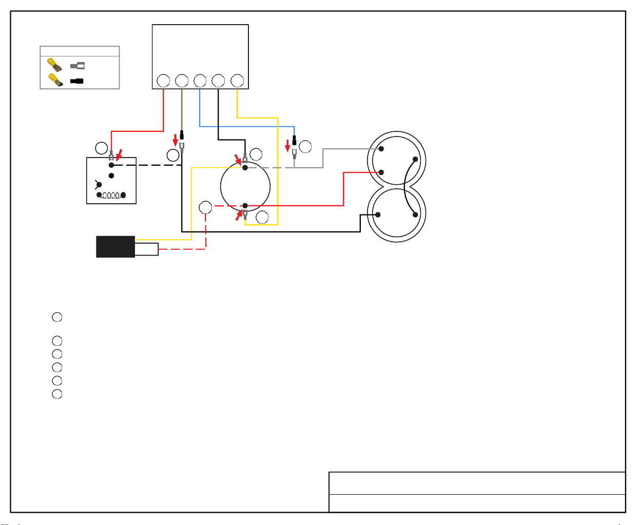
TURN ALL POWER OFF BEFORE STARTING INSTALLATION.
Route all SoftStart wires into the electrical box. Then crimp Connectors onto all SoftStart wires as indicated in drawing
Step 1
Step 2
Step 3
Step 4
Step 5
Step 6
Follow White Compressor Wire from Compressor to Run Capacitor “C” terminal. Disconnect from “C” terminal and connect it to Blue
SoftStart wire. Tape connection with electrical tape.
Connect Black SoftStart wire to the terminal that the White Compressor Wire was on.
Connect Yellow SoftStart wire on terminal next to Red Compressor Wire on "HERM" terminal of Run Capacitor.
IF there is a second Red wire next to the Red Compressor wire, disconnect it, seal end with electrical tape and drop it.
Follow Black Compressor Wire to Pressure Switch Relay. Disconnect it and connect to Brown SoftStart wire. Tape connection.
Connect Red SoftStart wire onto the terminal that the Black Compressor Wire was on.
Secure all wires. Tape connections with electrical tape.
Turn Power and A/C Breaker on. Turn A/C to Auto Cool setting and set the thermostat to 55ºF.
Look at SoftStart LED lights. Green light should be “on”. Green light means the Compressor is running (there may be a full 3-minute delay before
Green light comes on). IF there is no Green light after 4 minutes, call SoftStart Tech Support for assistance.
After establishing Green light operation, re-install all A/C covers.
Turn A/C on, set near to outdoor temperature and run for 30 minutes.
After 30 minutes, operate A/C normally.
Wiring Diagram for Coleman Mach 1976A727 (02-18) Relay
RED
FEMALE
BROWN
MALE
BLUE
MALE
BLACK
FEMALE
YELLOW
FEMALE
Soft
Start
5 6 1 2 3
5
4
3
2
1
2
1
RUN
CAPACITOR
HERM
3
6
WHITE
R
C
S
5
COMPRESSOR
PTCR 4
START
CAPACITOR
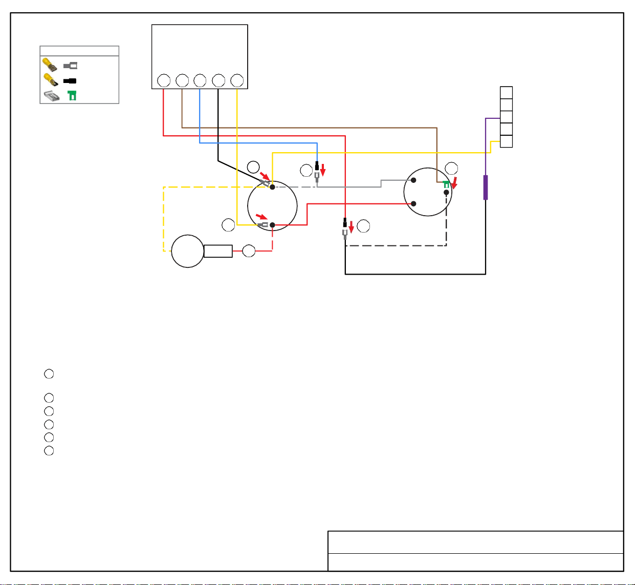
TURN ALL POWER OFF BEFORE STARTING INSTALLATION.
Route Black, Yellow and Blue SoftStart wires into the electrical box. Then crimp Connectors onto SoftStart wires as indicated in drawing.
Route Brown and Red SoftStart wires to the top of the Compressor. Then attach Connectors as indicated in drawing.
IF there are 3 Capacitors, perform Step 4. If there are NOT 3 Capacitors, skip Step 4.
Step
1
Step
2
Step
3
Step
4
Step
5
Step
6
Follow White Compressor wire from Compressor to Run Capacitor. Disconnect from terminal and connect it to Blue SoftStart wire.
Seal connection with electrical tape.
Connect Black SoftStart wire to the terminal that the White Compressor wire was on.
Connect Yellow SoftStart wire on terminal next to Red Compressor wire on HERM side of Run Capacitor.
IF there is a second Red wire next to Red Compressor wire on HERM side of Run Capacitor, disconnect it, seal end with tape and drop it.
Remove the Compressor Cap. Disconnect Black wire and connect to Red SoftStart wire. Tape connection.
Connect Brown SoftStart wire (with Female Flag connector) onto the terminal that the Black Compressor wire was on. Route Brown wire
out with Red and White Compressor wires. Replace cap.
Secure all wires. Tape connections with electrical tape.
Turn Power and A/C Breaker on. Turn A/C to Auto Cool setting and the thermostat to 55ºF.
Look at SoftStart LED lights. Green light should be “on”. Green light means the Compressor is running (there may be a full 3-minute delay before
Green light comes on). IF there is no Green light after 4 minutes, call SoftStart Tech Support for assistance.
After establishing Green light operation, re-install all A/C covers.
Turn A/C on, set near to outdoor temperature and run for 30 minutes.
After 30 minutes, operate A/C normally.
Wiring Diagram for Coleman Mach 1976A736 (6-18) NCF
FEMALE
MALE
FEMA LE FLAG
WIRE CONNECTOR GUIDE
BLACK
MALE
RED
FEMALE
FLAG
BROWN
MALE
BLUE
FEMALE
BLACK
FEMALE
YELLOW
PURPLE
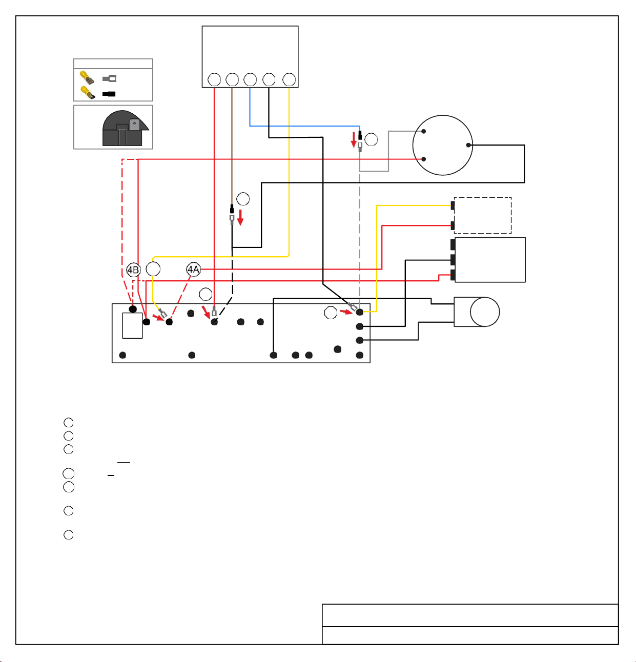
Soft
Start
WIRE CONNECTOR GUIDE
FEMALE
MALE
6 5 1 2 3
COMPRESSOR
RED
WHITE
R
1
C
S
BLACK
5
YELLOW
RED
START
CAPACITOR
(optional - applies to
Steps 3 and 4A)
3
PTCR
6
WHT
BLACK
RED
2
BLACK
BLACK
FAN
C
HERM
RUN
CAPACITOR
TERMINAL
BOARD
WHT
PTCR FREEZE
ORG
BLK
RED
BLU
PUR
BWN
REVERSING
VALVE
TURN ALL POWER OFF BEFORE STARTING INSTALLATION.
NOTE: There are two options for Step 4, depending on your existing connections. Read both options carefully before proceeding.
Route ALL SoftStart wires into the electrical box. Then crimp Connectors onto all SoftStart wires as indicated in drawing.
Step 1
Step 2
Step 3
Follow White Compressor wire to Terminal Board. Disconnect from Terminal Board and connect to Blue SoftStart wire.
Connect Black SoftStart wire to the terminal on the Terminal Board that the White Compressor Wire was on.
Connect Yellow SoftStart wire on terminal where PTCR is stamped on Terminal Board.
If there is not a black PTCR (looks like a black snail - see illustration above), skip Step 4 completely.
Step
4A
If there is a Start Capacitor and PTCR, disconnect the Red wire from the Terminal Board.
Step
4B
Disconnect PTCR from Terminal Board. Then disconnect the double Red wires from the PTCR and reconnect to terminal that the
PTCR was connected to.
Step 5
Step 6
Disconnect Black Compressor Wire from Freeze connection on Terminal Board. Connect Black Compressor Wire to Brown
SoftStart wire and tape connection with electrical tape.
Connect Red SoftStart wire to the terminal that the Black Compressor Wire was on.
Secure all wires. Tape connections with electrical tape.
Turn Power and A/C Breaker on. Turn A/C to Auto Cool setting and set the thermostat to 55ºF.
Look at SoftStart LED lights. Green light should be “on”. Green light means the Compressor is running (there may be a full 3-minute delay
before Green light comes on). IF there is no Green light after 4 minutes, call SoftStart Tech Support for assistance.
After establishing Green light operation, re-install all A/C covers.
Turn A/C on, set near to outdoor temperature and run for 30
minutes. After 30 minutes, operate A/C normally.
Wiring Diagram for Coleman Mach 1976A738 (6-20) TB
RED
PTCR
(black
snail)
FEMALE
BROWN
BLUE
MALE
BLACK
MALE
FEMALE
YELLOW
FEMALE
YEL
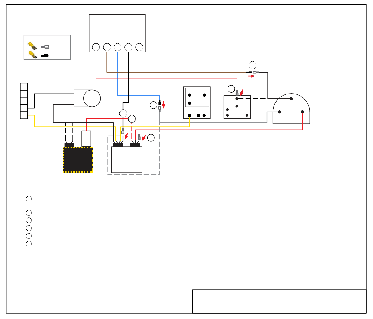
Soft
Start
WIRE CONNECTOR GUIDE
FEMALE
MALE
6 5 1 2 3
5
5
BLACK
4
3
2
BLACK
1
1
REVERSING
VALVE
2
4
3
N C NO
COM
NEUT
6
2
5
7
WHITE
RED
BLACK
R
COMPRESSOR
C
S
(OPTIONAL
CAPACITOR
- SEE STEP 4)
C HERM
RUN
CAPACITOR
TURN ALL POWER OFF BEFORE STARTING INSTALLATION.
Route all SoftStart wires into the electrical box. Then crimp Connectors onto all SoftStart wires as indicated in drawing.
Step
1
Step 2
Step 3
Step 4
Step 5
Step 6
Follow White Compressor Wire from Compressor to Run Capacitor “C” terminal. Disconnect from “C” terminal and connect it to Blue
SoftStart wire. Tape connection with electrical tape.
Connect Black SoftStart wire to the terminal that the White Compressor Wire was on.
Connect Yellow SoftStart wire on terminal next to Red Compressor Wire on HERM Side of Run Capacitor.
IF you see a second Red wire next to the Red Compressor Wire (from additional Capacitor), disconnect it and seal end with electrical tape.
Follow Black Compressor Wire to Relay. Disconnect Black wire and connect to Brown SoftStart wire. Tape connection.
Connect Red SoftStart wire onto the terminal that the Black Compressor Wire was on.
Secure all wires. Tape connections with electrical tape.
Turn Power and A/C Breaker on. Turn A/C to Auto Cool setting and set the thermostat to 55ºF.
Look at SoftStart LED lights. Green light should be “on”. Green light means the Compressor is running (there may be a full 3-minute delay before
Green light comes on). IF there is no Green light after 4 minutes, call SoftStart Tech Support for assistance.
After establishing Green light operation, re-install all A/C covers.
Turn A/C on, set near to outdoor temperature and run for 30 minutes.
After 30 minutes, operate A/C normally.
Wiring Diagram for Coleman Mach 1976A742 (11-20)
START
CAPACITOR
RED
PTCR
FEMALE
BROWN
MALE
BLUE
MALE
BLACK
FEMALE
YELLOW
FEMALE
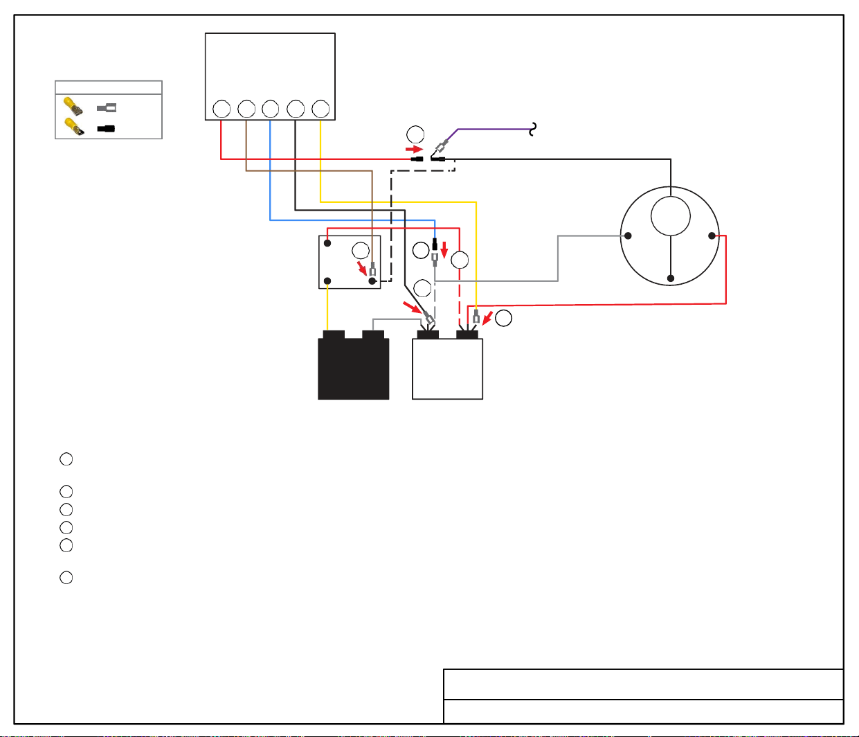
Soft
Start
6 5 1 2 3
6
BLACK
RED
2
5 1
START
4
RELAY
OL
R S
WHITE
C
1 5
2
WHITE
COMPRESSOR
3
RED COMPRESSOR WIRE
START
CAPACITOR
C HERM
RUN
CAPACITOR
TURN ALL POWER OFF BEFORE STARTING INSTALLATION.
Route Blue, Black and Yellow SoftStart wires into the electrical box. Then crimp Connectors onto all SoftStart wires as indicated in drawing.
Step
1
Step
2
Step 3
Step
4
Step 5
Step 6
Follow White Compressor Wire from Compressor to Run Capacitor “C” terminal. Disconnect from “C” terminal and connect it to Blue
SoftStart wire.
Connect Black SoftStart wire to the terminal that the White Compressor Wire was on.
Connect Yellow SoftStart wire on terminal next to Red Compressor Wire on "Herm" Side of Run Capacitor.
IF you see a second Red wire next to the Red Compressor Wire, disconnect it and seal end with electrical tape.
Follow Black Compressor wire to the Start Relay. Disconnect both Black and Purple wires, and connect them to Brown SoftStart wire.
Seal connection with electrical tape.
Connect Red SoftStart wire onto the terminal that the Black Compressor Wire was on.
Secure all wires. Tape connections with electrical tape.
Turn Power and A/C Breaker on. Turn A/C to Auto Cool setting and set the thermostat to 55ºF.
Look at SoftStart LED lights. Green light should be “on”. Green light means the Compressor is running (there may be a full 3-minute delay before
Green light comes on). IF there is no Green light after 4 minutes, call SoftStart Tech Support for assistance.
After establishing Green light operation, re-install all A/C covers.
Turn A/C on, set near to outdoor temperature and run for 30 minutes.
After 30 minutes, operate A/C normally.
Coleman Mach 1976B031 (9-85) Relay
FEMALE
MALE
WIRE CONNECTOR GUIDE
RED
MALE
BROWN
FEMALE
BLUE
MALE
BLACK
FEMALE
YELLOW
FEMALE
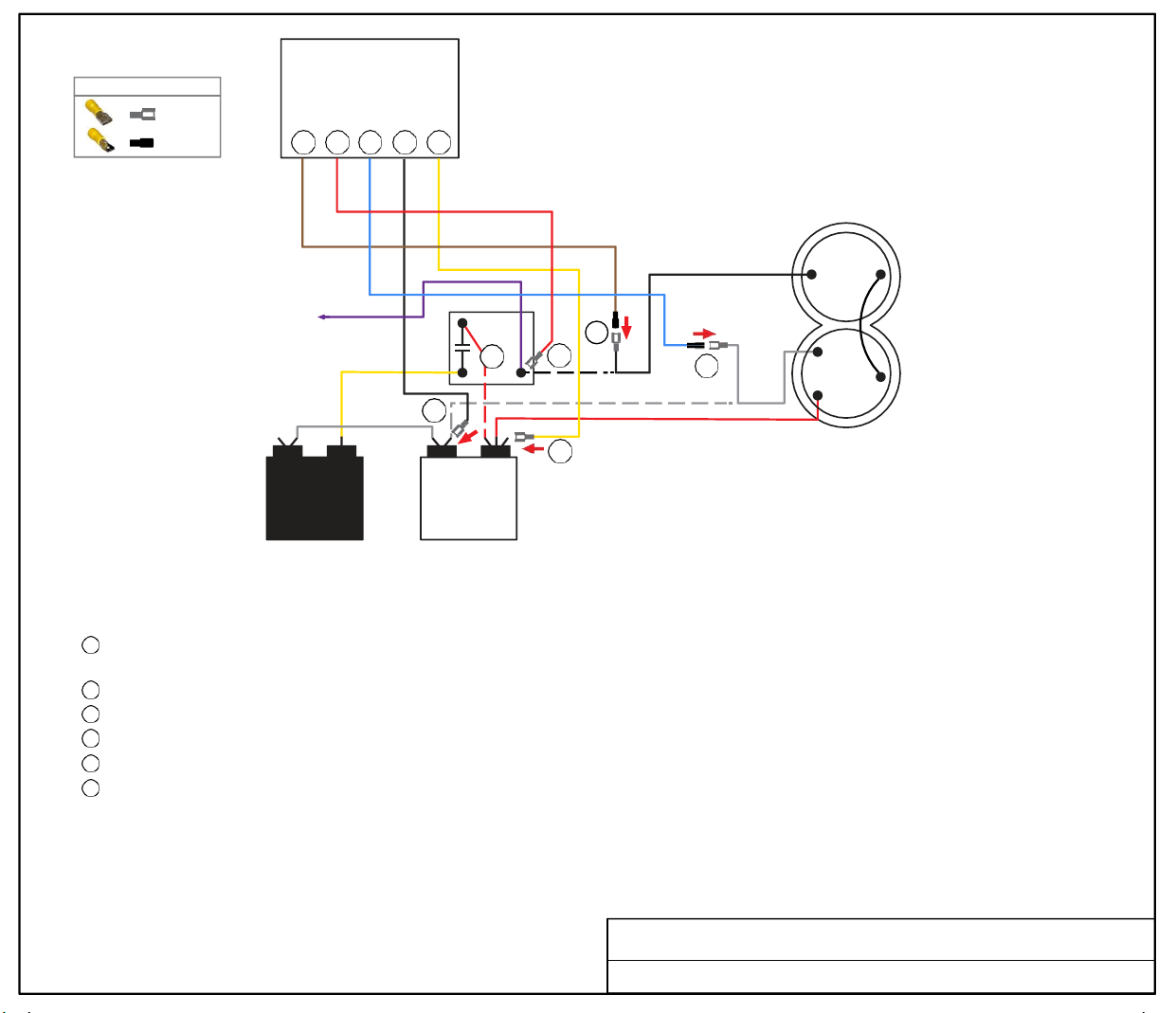
FEMALE
MALE
WIRE CONNECTOR GUIDE
5 6 1 2 3
Soft
Start
2
5
RELAY
4
6
BLACK
COMPRESSOR
R
1 5
1
2
C
WHITE
S
START
CAPACITOR
3
C HERM
RUN
CAPACITOR
RED COMPRESSOR WIRE
TURN ALL POWER OFF BEFORE STARTING INSTALLATION.
Route ALL SoftStart wires into the electrical box. Then crimp Connectors onto all SoftStart wires as indicated in drawing.
Step
1
Step
2
Step
3
Step
4
Step
5
Step
6
Follow White Compressor wire from Compressor to Run Capacitor “C” terminal. Disconnect from “C” terminal and connect it to Blue
SoftStart wire. Seal connection with electrical tape.
Connect Black SoftStart wire to the terminal that the White Compressor wire was on.
Connect Yellow SoftStart wire on terminal next to Red Compressor wire on HERM side of Run Capacitor.
If there is another Red wire next to the Red Compressor wire, disconnect it from Run Capacitor. Seal end with electrical tape and drop it.
Follow Black Compressor wire to Relay. Disconnect Black wire from Relay and connect to Brown SoftStart wire. Tape connection.
Connect Red SoftStart wire onto the Relay terminal that the Black Compressor wire was on.
Secure all wires. Seal connections with electrical tape.
Turn Power and A/C Breaker on. Turn A/C to Auto Cool setting and set the thermostat to 55ºF.
Look at SoftStart LED lights. Green light should be “on”. Green light means the Compressor is running (there may be a full 3-minute delay before
Green light comes on). IF there is no Green light after 4 minutes, call SoftStart Tech Support for assistance.
After establishing Green light operation, re-install all A/C covers.
Turn A/C on, set near to outdoor temperature and run for 30 minutes.
After 30 minutes, operate A/C normally.
Wiring Diagram for Coleman Mach 1976B037 Relay
BROWN
MALE
RED
FEMALE
BLUE
MALE
BLACK
FEMALE
YELLOW
FEMALE
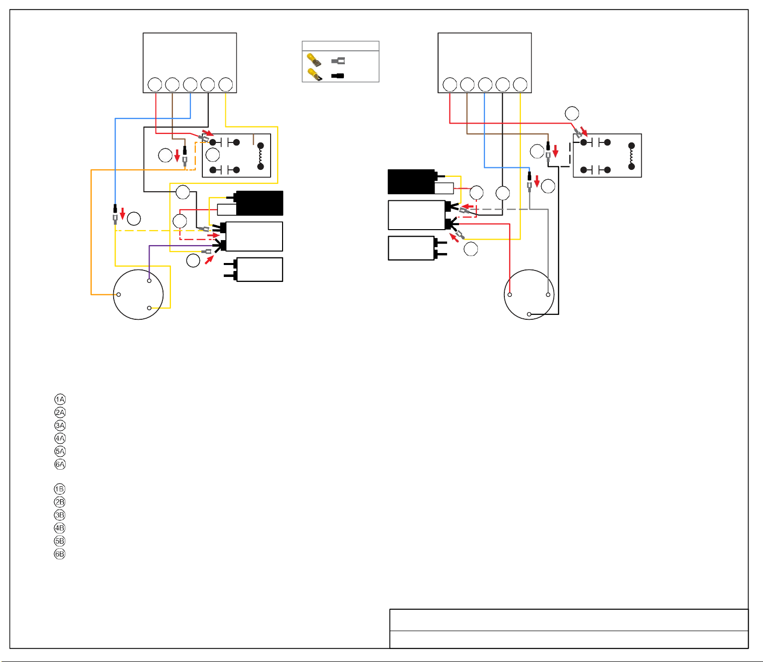
FAN
YEL
Soft
Start
6A 5A 1A 2A 3A
6B
5A
6A
5B
RELAY
2A
1A
4A
PTCR
C
START
CAPACITOR
RUN
CAPACITOR
1B
4B
2B
RELAY
HERM
3A
A
3B
FAN
S
C
S
R
R
C
COMPRESSOR
A
COMPRESSOR
B
TURN ALL POWER OFF BEFORE STARTING INSTALLATION.
Route ALL SoftStart wires into the electrical box. Then crimp Connectors onto all SoftStart wires as indicated in drawing.
NOTE: Instructions are separate for Compressors A and B because wires colors are different. Work with one Compressor and one SoftStart at a time to avoid confusion.
COMPRESSOR A INSTRUCTIONS
Step Follow the Yellow Compressor wire to the "C" terminal of the Run Capacitor. Disconnect and connect to the Blue SoftStart wire.
Step Connect Black SoftStart wire to the terminal on the Run Capacitor that the Yellow Compressor wire was on.
Step Connect the Yellow SoftStart wire on a terminal next to the Purple Compressor wire on the Herm terminals.
Step Disconnect the PTCR Red wire from the Herm Run Capacitor. Seal end with electrical tape and drop it.
Step Follow Orange Compressor wire to the relay. Disconnect and connect to the Brown SoftStart wire. Tape connection.
Step Connect the Red SoftStart wire on the terminal that the Orange Compressor wire was on.
COMPRESSOR B INSTRUCTIONS
Step Follow White Compressor wire to "C" terminal of Run Capacitor. Disconnect and connect to Blue Softstart wire. Tape connection.
Step Connect Black SoftStart wire to the terminal on the Run Capacitor that the White Compressor Wire was on.
Step Connect Yellow SoftStart wire on a terminal next to the Red Compressor wire.
Step Disconnect the PTCR Red wire from the Herm Run Capacitor. Seal end with electrical tape and drop it.
Step Follow Black compressor wire to the relay. Disconnect and connect to the Brown SoftStart wire. Tape connection.
Step Connect the Red SoftStart wire on the Terminal the Black Compressor wire was on. Secure all wires. Tape connections with electrical tape.
Turn Power and A/C Breaker on. Turn A/C to Auto Cool setting and set the thermostat to 55ºF.
Look at SoftStart LED lights. Green light should be “on”. Green light means the Compressor is running (there may be a full 3-minute delay before Green light comes on). IF there
is no Green light after 4 minutes, call SoftStart Tech Support for assistance.
After establishing Green light operation, re-install all A/C covers. Turn A/C on, set
near to outdoor temperature and run for 30 minutes. After 30 minutes, operate A/C
normally.
Wiring Diagram for Coleman Dual Basement 1976B119 (02-94)
FEMALE
MALE
WIRE CONNECTOR GUIDE
C
HERM
RUN
CAPACITOR
B
PTCR
6B 5B 1B 2B 3B
START
CAPACITOR
Soft
Start
ORG
RED
PUR
FEMALE
BROWN
MALE
MALE
BLUE
FEMALE
BLACK
FEMALE
YELLOW
FEMALE
RED
MALE
BROWN
MALE
BLUE
FEMALE
BLACK
YELLOW
RED
FEMALE
WHITE
BLACK
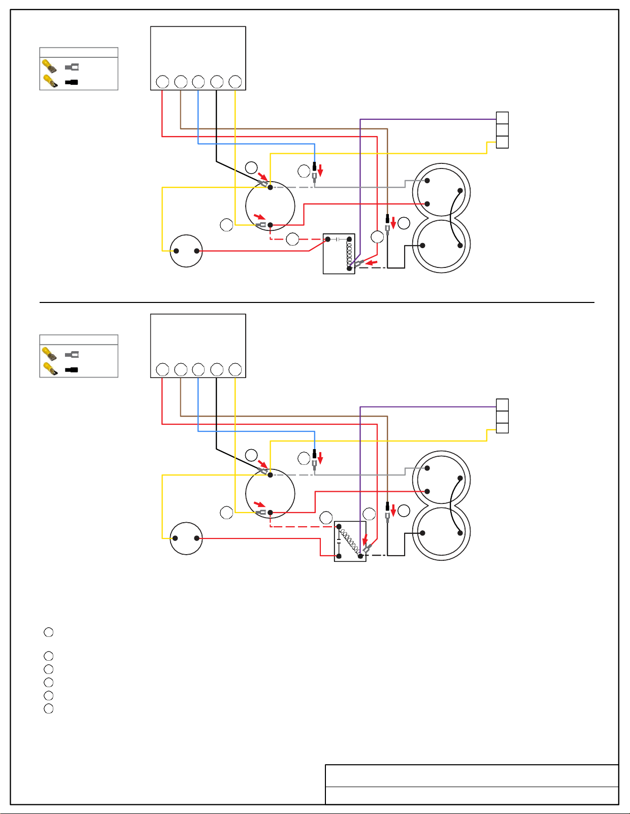
FEMALE
MALE
WIRE CONNECTOR GUIDE
6 5 1 2 3
1
2
3
Soft
Start
6 5 1 2 3
3
2
1
A
[WITH
TIMED MOTOR
STARTING RELAY]
2
1
RUN
CAPACITOR
HERM
3
4
WHITE
R
C
S
5
6
L2
START
CAPACITOR
L1
START
RELAY
BLACK
COMPRESSOR
Soft
Start
B
[WITH
POTENTIAL MOTOR
STARTING RELAY]
2
1
RUN
CAPACITOR
HERM
3
4
2
WHITE
R
C
S
6
5
START
CAPACITOR
1 5
START
RELAY
BLACK
COMPRESSOR
TURN ALL POWER OFF BEFORE STARTING INSTALLATION.
NOTE: The instructions for diagrams A and B are the same. The difference is the type of Start Relay used in the A/C system.
Route ALL SoftStart wires into the electrical box. Then crimp Connectors onto all SoftStart wires as indicated in drawing.
Step
1
Step
2
Step
3
Step
4
Step
5
Step
6
Follow White Compressor wire from Compressor to Run Capacitor. Disconnect from terminal and connect it to Blue SoftStart wire. Seal
connection with electrical tape.
Connect Black SoftStart wire to the terminal that the White Compressor wire was on.
Connect Yellow SoftStart wire on terminal next to Red Compressor wire on HERM side of Run Capacitor.
IF there is a second Red wire next to Red Compressor wire on HERM side of Run Capacitor, disconnect it, seal end with tape and drop it.
Follow Black Compressor wire to the Start Relay and disconnect it. Connect Black wire to the Brown SoftStart wire. Tape connection.
Connect the Red SoftStart wire onto the terminal that the Black Compressor wire was on.
Turn Power and A/C Breaker on. Turn A/C to Auto Cool setting and set the thermostat to 55ºF.
Look at SoftStart LED lights. Green light should be “on”. Green light means the Compressor is running (there may be a full 3-minute delay before
Green light comes on). IF there is no Green light after 4 minutes, call SoftStart Tech Support for assistance.
Re-install all A/C covers.
Turn A/C on, set near to outdoor temperature and run for 30 minutes.
After 30 minutes, operate A/C normally.
Wiring Diagram for Coleman Mach 1976B136 (2-95)
FEMALE
MALE
WIRE CONNECTOR GUIDE
RED
RED
FEMALE
FEMALE
BROWN
BROWN
MALE
MALE
BLUE
BLUE
MALE
MALE
BLACK
BLACK
FEMALE
FEMALE
YELLOW
YELLOW
FEMALE
FEMALE
CAP
PURPLE
PURPLE
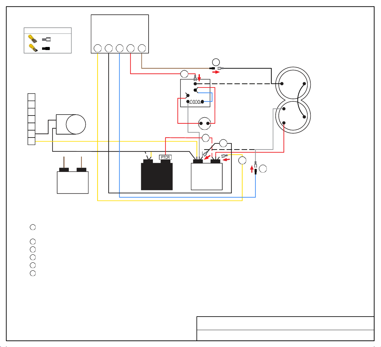
Soft
Start
WIRE CONNECTOR GUIDE
FEMALE
MALE
7
6
3 2 1 6 5
6
PRESSURE
2
SWITCH
RELAY
5
7
5
BLACK
COMPRESSOR
5
REVERSING
VALVE
4
3
2
1
FAN
CAPACITOR
START
CAPACITOR
4
2
3
C HERM
RUN
CAPACITOR
WHITE
1
R
C
S
RED
TURN ALL POWER OFF BEFORE STARTING INSTALLATION.
Route all SoftStart wires into the electrical box. Then crimp Connectors onto all SoftStart wires as indicated in drawing.
Step 1
Step 2
Step 3
Step 4
Step 5
Step 6
Follow White Compressor wire from Compressor to Run Capacitor “C” terminal. Disconnect from “C” terminal and connect it to Blue
SoftStart wire. Tape connection with electrical tape.
Connect Black SoftStart wire to the terminal that the White Compressor wire was on.
Connect Yellow SoftStart wire on terminal next to Red Compressor wire on HERM terminal of Run Capacitor.
IF there is a second Red wire next to the Red Compressor wire, disconnect it, seal end with electrical tape and drop it.
Follow Black Compressor wire to Pressure Switch Relay. Disconnect it and connect to Brown SoftStart wire. Tape connection.
Connect Red SoftStart wire onto the terminal that the Black Compressor wire was on.
Secure all wires. Tape connections with electrical tape.
Turn Power and A/C Breaker on. Turn A/C to Auto Cool setting and set the thermostat to 55ºF.
Look at SoftStart LED lights. Green light should be “on”. Green light means the Compressor is running (there may be a full 3-minute delay before
Green light comes on). IF there is no Green light after 4 minutes, call SoftStart Tech Support for assistance.
After establishing Green light operation, re-install all A/C covers.
Turn A/C on, set near to outdoor temperature and run for 30 minutes.
After 30 minutes, operate A/C normally.
Wiring Diagram for Coleman Mach 1976B519 (7-13)
BRN/
WHT
BRN
YELLOW
FEMALE
BLACK
FEMALE
BLUE
MALE
RED
FEMALE
BROWN
MALE
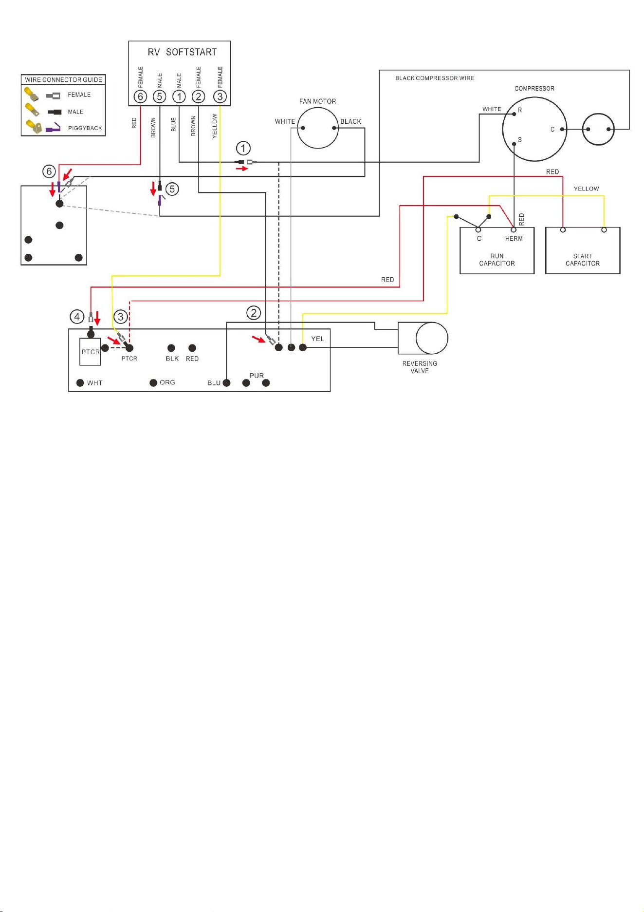
Coleman Mach 1976B603
Wiring Diagram for Coleman Mach 1976B603

Route ALL SoftStart wires into the electrical box. Then crimp Connectors onto all SoftStart wires as
indicated in drawing.
Step 1. Follow White Compressor wire to Run Capacitor. Disconnect from Run Capacitor and connect
to Blue SoftStart wire.
Step 2. Connect Black SoftStart wire to the terminal on the Run Capacitor that the White Compressor
wire was on.
Step 3. Disconnect single Red wire next to PTCR (running from Start Capacitor) and tape end with
electrical tape. Connect Yellow SoftStart wire on terminal that the Red wire was on.
Step 4. Disconnect PTCR. Disconnect Red wire from PTCR and connect Red wire on terminal that the
PTCR was on.
Step 5. Follow Black Compressor wire to Pressure Switch Relay and disconnect it from Relay. Also,
disconnect Black Fan wire from Black Compressor wire. Connect Black Compressor wire to Brown
SoftStart wire and tape connection with electrical tape.
Step 6. Connect Red SoftStart wire to Pressure Switch Relay. Connect Black Fan wire to male
Terminal on Red SoftStart wire (use piggyback connector).
Secure wires to prevent Fan from pulling wires in. Tape connections with electrical tape.
Turn Power and A/C Breaker on. Turn A/C to Auto Cool setting and set the thermostat to 55ºF.
Look at SoftStart LED lights. Green light should be “on”. Green light means the Compressor is
running (there may be a full 3-minute delay before Green light comes on). IF there is no Green light
after 4 minutes, call SoftStart Tech Support for assistance.
After establishing Green light operation, re-install all A/C covers. Turn A/C on, set near to outdoor
temperature and run for 30 minutes. After 30 minutes, operate A/C normally.
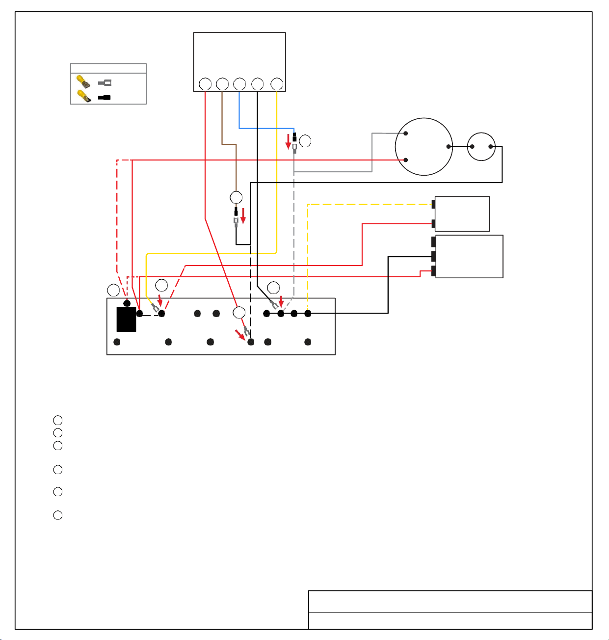
FEMALE
MALE
WIRE CONNECTOR GUIDE
6 5 1 2 3
Soft
Start
COMPRESSOR
RED
WHITE
R
1
C
S
BLACK
5
YELLOW
RED
(optional)
BLACK
RED
3
PTCR
PTCR
BLK
6
RED
YEL
WHT
BLU
PUR
TERMINAL
BOARD
TURN ALL POWER OFF BEFORE STARTING INSTALLATION.
Route ALL SoftStart wires into the electrical box. Then crimp Connectors onto all SoftStart wires as indicated in drawing.
Step
1
Step
2
Step
3
Step
4
Step 5
Step 6
Follow White Compressor wire to Terminal Board. Disconnect from Terminal Board and connect to Blue SoftStart wire.
Connect Black SoftStart wire to the terminal on the Terminal Board that the White Compressor Wire was on.
Disconnect black PTCR from board. Disconnect the double Red wires from PTCR and connect them to PTCR terminal
(stamped on Terminal Board).
Disconnect the single Red wire on terminal next to PTCR and seal end with tape. Connect Yellow SoftStart wire to the terminal
that the single Red wire was on.
Disconnect Black Compressor wire from Terminal Board. Connect Black Compressor wire to Brown SoftStart wire and tape
connection with electrical tape.
Connect Red SoftStart wire to the terminal that the Black Compressor wire was on.
Secure all wires. Tape connections with electrical tape.
Turn Power and A/C Breaker on. Turn A/C to Auto Cool setting and set the thermostat to 55ºF.
Look at SoftStart LED lights. Green light should be “on”. Green light means the Compressor is running (there may be a full 3-minute delay
before Green light comes on). IF there is no Green light after 4 minutes, call SoftStart Tech Support for assistance.
After establishing Green light operation, re-install all A/C covers.
Turn A/C on, set near to outdoor temperature and run for 30 minutes.
After 30 minutes, operate A/C normally.
Wiring Diagram for Coleman Mach 1976B613 (01-16) TB
2
4
FAN
C
RUN
CAPACITOR
HERM
START
CAPACITOR
FEMALE
RED
MALE
BROWN
MALE
BLUE
FEMALE
BLACK
FEMALE
YELLOW
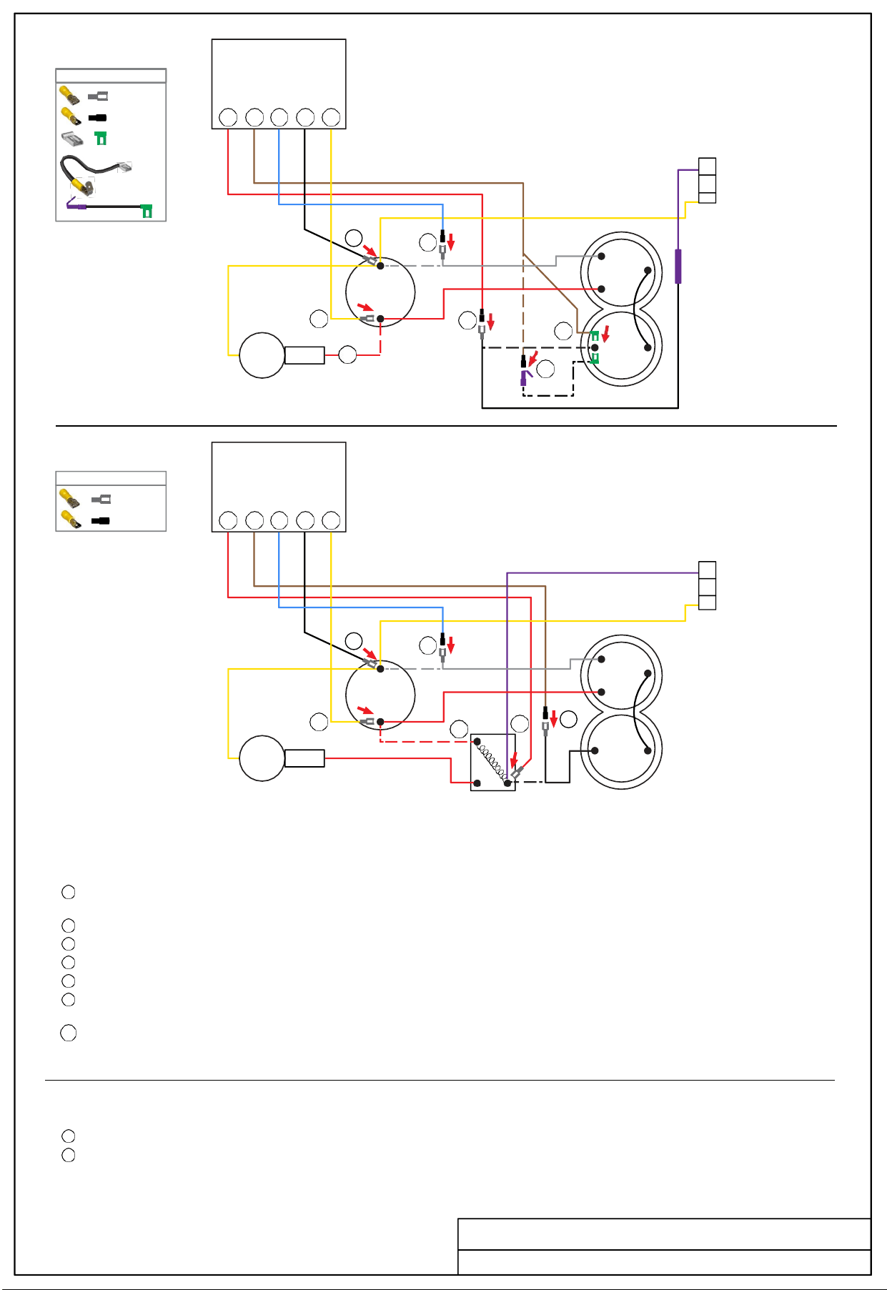
WIRE CONNECTOR GUIDE
FEMALE
MALE
FEMALE FLAG
5 6 1 2 3
FEMALE
MALE
WIRE CONNECTOR GUIDE
6 5 1 2 3
1
2
3
Soft
Start
A
[WITHOUT
START RELAY]
3
PTCR
START
CAPACITOR
2
1
RUN
CAPACITOR
HERM
5
4
WHITE
6
6P
COMPRESSOR
Soft
Start
B
[INCLUDES
START RELAY]
2
1
RUN
CAPACITOR
HERM
3
4
WHITE
6
5
PTCR
START
CAPACITOR
START
RELAY
BLACK
COMPRESSOR
TURN ALL POWER OFF BEFORE STARTING INSTALLATION.
A
Route Blue, Black and Yellow SoftStart wires into the electrical box. Route the Brown and Red wires to the top of the Compressor. Crimp
connectors onto ends of SoftStart wires as indicated in drawing.
Step 1
Step 2
Step 3
Step 4
Step 5
Step 6
Follow White Compressor wire from Compressor to Run Capacitor. Disconnect from terminal and connect it to Blue SoftStart wire. Seal
connection with electrical tape.
Connect Black SoftStart wire to the terminal that the White Compressor wire was on.
Connect Yellow SoftStart wire on terminal next to Red Compressor wire on HERM side of Run Capacitor.
IF there is a second Red wire next to Red Compressor wire on HERM side of Run Capacitor, disconnect it, seal end with tape and drop it.
Remove the Compressor Cap. Disconnect Black wire and connect to Red SoftStart wire. Tape connection. Do not put wires back under cap.
Connect Brown SoftStart wire (with Female Flag connector) onto the terminal that the Black Compressor wire was on. Route Brown
SoftStart wire out with Red and White Compressor wires. Replace cap.
Step 6P [OPTIONAL] Connect Female Flag end of 4” PigTail onto the terminal that the Black Compressor wire was on. Crimp Male connector onto
Brown SoftStart wire, then connect it to Female side of Piggyback connector. Break off unused tangent from Piggyback connector. Route
Pigtail wire out with Red and White wires and replace cap.
B
Route all SoftStart wires into the electrical box. Crimp connectors onto ends of SoftStart wires as indicated in drawing.
Repeat Steps 1 through 4 from instructions above.
Step
5
Follow Black Compressor wire to the Start Relay and disconnect it. Connect Black wire to the Brown SoftStart wire. Tape connection.
Step
6
Connect the Red SoftStart wire onto the terminal that the Black Compressor wire was on.
Turn Power and A/C Breaker on. Turn A/C to Auto Cool setting and set the thermostat to 55ºF.
Look at SoftStart LED lights. Green light should be “on”. Green light means the Compressor is running (there may be a full 3-minute delay before
Green light comes on). IF there is no Green light after 4 minutes, call SoftStart Tech Support for assistance.
Re-install all A/C covers.
Turn A/C on, set near to outdoor temperature and run for 30 minutes.
After 30 minutes, operate A/C normally.
Wiring Diagram for Coleman Mach 1976C136 (08-97)
1
2
3
2
1 5
4” PIGTAIL
w/
FEMALE FLAG
& PIGGYBACK
OR
BLACK
RED
RED
FEMALE
MALE
BROWN
BROWN
MALE
FEMALE
FLAG
BLUE
BLUE
MALE
MALE
BLACK
BLACK
FEMALE
FEMALE
YELLOW
YELLOW
FEMALE
FEMALE
PURPLE
PURPLE
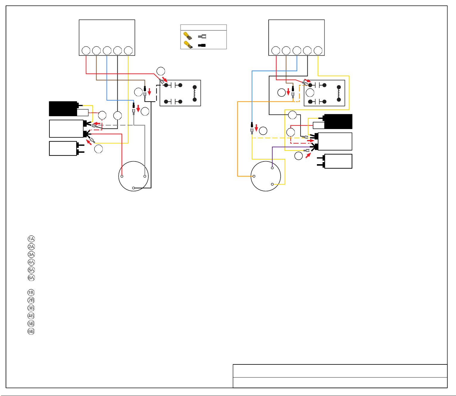
WHITE
BLACK
ORG
PUR
Soft
Start
6B 5B 1B 2B 3B
6A
5A
5B 6B
1A
4A
2A
2B
1B
4B
PTCR
C
START
CAPACITOR
RUN
CAPACITOR
3A
HERM
B
3B
FAN
S
S
R C
C
R
COMPRESSOR
A
COMPRESSOR
B
TURN ALL POWER OFF BEFORE STARTING INSTALLATION.
Route ALL SoftStart wires into the electrical box. Then crimp Connectors onto all SoftStart wires as indicated in drawing.
NOTE: Instructions are separate for Compressors A and B because wires colors are different. Work with one Compressor and one SoftStart at a time to avoid confusion.
COMPRESSOR A INSTRUCTIONS
Step Follow White Compressor wire to "C" terminal of Run Capacitor. Disconnect and connect to Blue SoftStart wire. Tape connection.
Step Connect Black SoftStart wire to the terminal on the Run Capacitor that the White Compressor Wire was on.
Step Connect Yellow SoftStart wire on a terminal next to the Red Compressor wire.
Step Disconnect the PTCR Red wire from the Herm Run Capacitor. Seal end with electrical tape and drop it.
Step Follow Black compressor wire to the relay. Disconnect and connect to the Brown SoftStart wire. Tape connection.
Step Connect the Red SoftStart wire on the Terminal the Black Compressor wire was on.
COMPRESSOR B INSTRUCTIONS
Step Follow the Yellow Compressor wire to the "C" terminal of the Run Capacitor. Disconnect and connect to the Blue SoftStart wire.
Step Connect Black SoftStart wire to the terminal on the Run Capacitor that the Yellow Compressor wire was on.
Step Connect the Yellow SoftStart wire on a terminal next to the Purple Compressor wire on the Herm terminals.
Step Disconnect the PTCR Red wire from the Herm Run Capacitor. Seal end with electrical tape and drop it.
Step Follow Orange Compressor wire to the relay. Disconnect and connect to the Brown SoftStart wire. Tape connection.
Step Connect the Red SoftStart wire on the terminal that the Orange Compressor wire was on.
Secure all wires. Tape connections with electrical tape.
Turn Power and A/C Breaker on. Turn A/C to Auto Cool setting and set the thermostat to 55ºF.
Look at SoftStart LED lights. Green light should be “on”. Green light means the Compressor is running (there may be a full 3-minute delay before Green light comes on).
IF there is no Green light after 4 minutes, call SoftStart Tech Support for assistance.
After establishing Green light operation, re-install all A/C covers. Turn A/C on, set near
to outdoor temperature and run for 30 minutes. After 30 minutes, operate A/C normally.
Wiring Diagram for Coleman Dual Basement 1976C304 (12-00)
FEMALE
MALE
WIRE CONNECTOR GUIDE
FAN
C
HERM
PTCR
RUN
CAPACITOR
A
6A 5A 1A 2A 3A
START
CAPACITOR
Soft
Start
RED
FEMALE
BROWN
MALE
BLUE
MALE
BLACK
FEMALE
RED
FEMALE
YELLOW
RED
FEMALE
MALE
BROWN
BLUE
YEL
MALE
BLACK
FEMALE
YELLOW
FEMALE
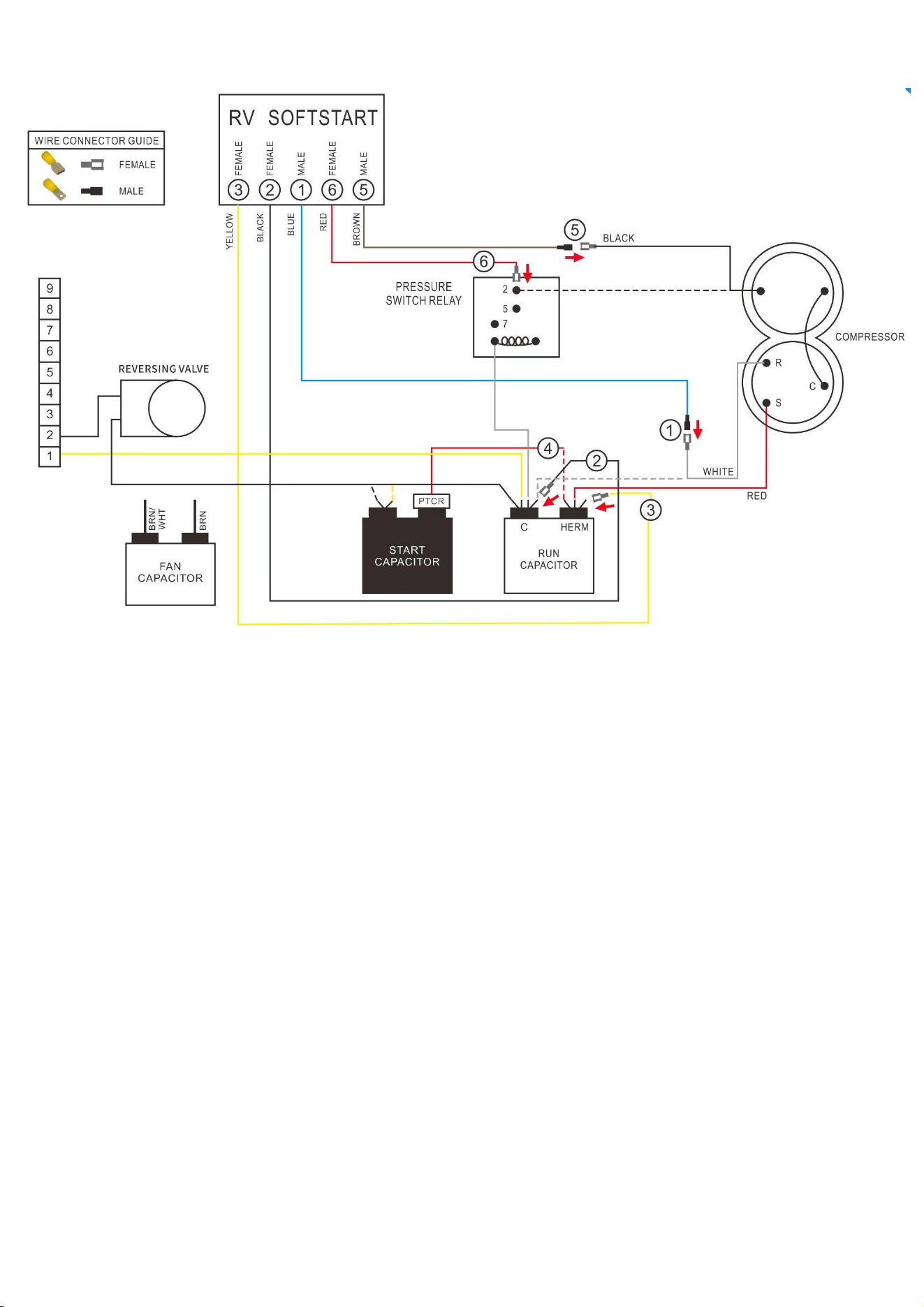
Coleman Mach 1976C519
Wiring Diagram for Coleman Mach 1976C519

Coleman Mach 1976C519
Route all SoftStart wires into the electrical box. Then crimp Connectors onto all SoftStart wires as
indicated in drawing.
Step 1. Follow White Compressor wire from Compressor to Run Capacitor “C” terminal. Disconnect
from “C” terminal and connect it to Blue SoftStart wire. Tape connection with electrical tape.
Step 2. Connect Black SoftStart wire to the terminal that the White Compressor wire was on.
Step 3. Connect Yellow SoftStart wire on terminal next to Red Compressor wire on HERM terminal of
Run Capacitor.
Step 4. IF there is a second Red wire next to the Red Compressor wire, disconnect it, seal end with
electrical tape and drop it.
Step 5. Follow Black Compressor wire to Pressure Switch Relay terminal. Disconnect it and connect to
Brown SoftStart wire. Tape connection.
Step 6. Connect Red SoftStart wire onto the terminal that the Black Compressor wire was on.
Secure all wires. Tape connections with electrical tape.
Turn Power and A/C Breaker on. Turn A/C to Auto Cool setting and set the thermostat to 55ºF.
Look at SoftStart LED lights. Green light should be “on”. Green light means the Compressor is
running (there may be a full 3-minute delay before Green light comes on). IF there is no Green light
after 4 minutes, call SoftStart Tech Support for assistance.
After establishing Green light operation, re-install all A/C covers.
Turn A/C on, set near to outdoor temperature and run for 30 minutes. After 30 minutes, operate A/C
normally.
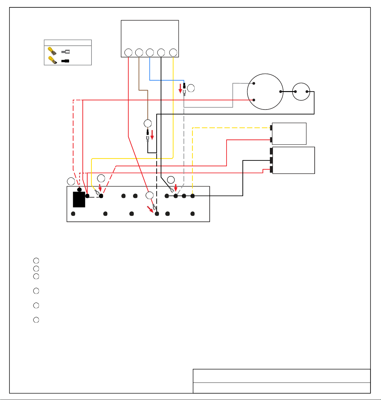
FEMALE
MALE
WIRE CONNECTOR GUIDE
6 5 1 2 3
Soft
Start
COMPRESSOR
RED
WHITE
R
1
C
S
BLACK
5
YELLOW
RED
(optional)
BLACK
RED
3
PTCR
PTCR
BLK
6
RED
YEL
WHT
BLU
PUR
TERMINAL
BOARD
TURN ALL POWER OFF BEFORE STARTING INSTALLATION.
Route ALL SoftStart wires into the electrical box. Then crimp Connectors onto all SoftStart wires as indicated in drawing.
Step
1
Step 2
Step
3
Step
4
Step 5
Step 6
Follow White Compressor wire to Terminal Board. Disconnect from Terminal Board and connect to Blue SoftStart wire.
Connect Black SoftStart wire to the terminal on the Terminal Board that the White Compressor wire was on.
Disconnect black PTCR from board. Disconnect the double Red wires from PTCR and connect them to PTCR terminal
(stamped on Terminal Board).
Disconnect the single Red wire on terminal next to PTCR and seal end with tape. Connect Yellow SoftStart wire to the terminal
that the single Red wire was on.
Disconnect Black Compressor wire from Terminal Board. Connect Black Compressor wire to Brown SoftStart wire and tape
connection with electrical tape.
Connect Red SoftStart wire to the terminal that the Black Compressor Wire was on.
Secure all wires. Tape connections with electrical tape.
Turn Power and A/C Breaker on. Turn A/C to Auto Cool setting and set the thermostat to 55ºF.
Look at SoftStart LED lights. Green light should be “on”. Green light means the Compressor is running (there may be a full 3-minute delay
before Green light comes on). IF there is no Green light after 4 minutes, call SoftStart Tech Support for assistance.
After establishing Green light operation, re-install all A/C covers.
Turn A/C on, set near to outdoor temperature and run for 30 minutes.
After 30 minutes, operate A/C normally.
Wiring Diagram for Coleman Mach 1976C613 (05-17) TB
2
4
FAN
C
RUN
CAPACITOR
HERM
START
CAPACITOR
FEMALE
RED
MALE
BROWN
MALE
BLUE
FEMALE
BLACK
FEMALE
YELLOW
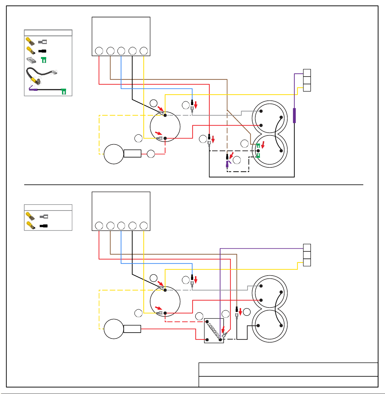
WIRE CONNECTOR GUIDE
OR
Soft
Start
5 6 1 2 3
3
2
1
A
[WITHOUT
START RELAY]
3
PTCR
START
CAPACITOR
2
1
RUN
CAPACITOR
HERM
5
4
WHITE
6
6P
COMPRESSOR
Soft
Start
6 5 1 2 3
3
2
1
B
[INCLUDES
START RELAY]
3
PTCR
2
1
RUN
CAPACITOR
HERM
4
2
WHITE
6
5
START
CAPACITOR
1 5
START
RELAY
BLACK
COMPRESSOR
Wiring Diagram for Coleman Mach 1976D136 (4-09)
FEMALE
MALE
WIRE CONNECTOR GUIDE
FEMALE
MALE
FEMALE FLAG
4” PIGTAIL
w/
FEMALE FLAG
& PIGGYBACK
BLACK
RED
RED
FEMALE
MALE
BROWN
BROWN
MALE
FEMALE
FLAG
BLUE
BLUE
MALE
MALE
BLACK
BLACK
FEMALE
FEMALE
YELLOW
YELLOW
FEMALE
FEMALE
PURPLE
PURPLE
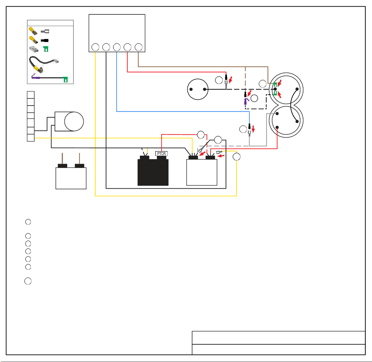
OR
Soft
Start
3 2 1 5 6
4” PIGTA IL
w/
FEMALE FLAG
&
PIGGYBACK
REVERSING
VALVE
OUTDOOR
FREEZE
SWITCH
5
BLACK
4
2
6
6P
COMPRESSOR
R
C
1
S
WHITE
RED
3
FAN
CAPACITOR
START
CAPACITOR
TURN ALL POWER OFF BEFORE STARTING INSTALLATION.
Route all SoftStart wires into the electrical box. Then crimp Connectors onto all SoftStart wires as indicated in drawing.
Step 1
Step 2
Step 3
Step 4
Step 5
Step 6
Follow White Compressor wire from Compressor to Run Capacitor “C” terminal. Disconnect from “C” terminal and connect it to
Blue SoftStart wire. Seal connection with electrical tape.
Connect Black SoftStart wire to the terminal that the White Compressor wire was on.
Connect Yellow SoftStart wire on terminal next to Red Compressor wire on HERM terminal of Run Capacitor.
IF there is a second Red wire next to the Red Compressor wire, disconnect it, seal end with electrical tape and drop it.
Remove the Compressor Cap. Disconnect Black wire and connect to Red SoftStart wire. Tape connection. Do not put wires back under cap.
Connect Brown SoftStart wire (with Female Flag connector) onto the terminal that the Black Compressor wire was on. Route Brown
SoftStart wire out with Red and White Compressor wires. Replace cap.
Step 6P [OPTIONAL] Connect Female Flag end of 4” PigTail onto the terminal that the Black Compressor wire was on. Crimp Male connector onto
Brown SoftStart wire, then connect it to Female side of Piggyback connector. Break off unused tangent from Piggyback connector. Route
Pigtail wire out with Red and White wires and replace cap.
Secure all wires. Tape connections with electrical tape.
Turn Power and A/C Breaker on. Turn A/C to Auto Cool setting and set the thermostat to 55ºF.
Look at SoftStart LED lights. Green light should be “on”. Green light means the Compressor is running (there may be a full 3-minute delay before
Green light comes on). IF there is no Green light after 4 minutes, call SoftStart Tech Support for assistance.
After establishing Green light operation, re-install all A/C covers.
Turn A/C on, set near to outdoor temperature and run for 30 minutes.
After 30 minutes, operate A/C normally.
Wiring Diagram for Coleman Mach 1976D519 (6-14)
1
2
3
4
5
6
7
C HERM
RUN
CAPACITOR
WIRE CONNECTOR GUIDE
FEMALE
MALE
FEMA LE FLAG
BRN/
WHT
BRN
YELLOW
FEMALE
BLACK
FEMALE
BLUE
MALE
RED
MALE
FEMALE
FLAG
BROWN
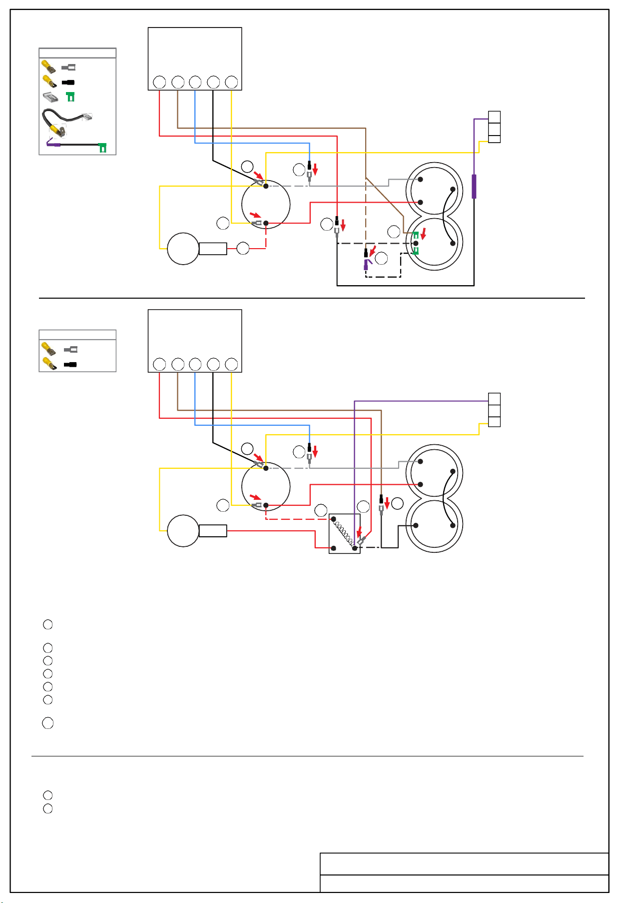
WIRE CONNECTOR GUIDE
FEMALE
MALE
FEMALE FLAG
5 6 1 2 3
FEMALE
MALE
WIRE CONNECTOR GUIDE
6 5 1 2 3
1
2
3
Soft
Start
A
[WITHOUT
START RELAY]
START
2
1
C
RUN
CAPACITOR
HERM
3
5
4
WHITE
R
C
S
6
6P
CAPACITOR
COMPRESSOR
Soft
Start
B
[INCLUDES
START RELAY]
2
1
C
RUN
CAPACITOR
HERM
3
4
WHITE
R
C
S
6
5
PTCR
START
CAPACITOR
START
RELAY
BLACK
COMPRESSOR
TURN ALL POWER OFF BEFORE STARTING INSTALLATION.
A
Route Blue, Black and Yellow SoftStart wires into the electrical box. Route the Brown and Red wires to the top of the Compressor. Crimp
connectors onto ends of SoftStart wires as indicated in drawing.
Step 1
Step 2
Step 3
Step 4
Step 5
Step 6
Follow White Compressor wire from Compressor to Run Capacitor. Disconnect from terminal and connect it to Blue SoftStart wire. Seal
connection with electrical tape.
Connect Black SoftStart wire to the terminal that the White Compressor wire was on.
Connect Yellow SoftStart wire on terminal next to Red Compressor wire on HERM side of Run Capacitor.
IF there is a second Red wire next to Red Compressor wire on HERM side of Run Capacitor, disconnect it, seal end with tape and drop it.
Remove the Compressor Cap. Disconnect Black wire and connect to Red SoftStart wire. Tape connection. Do not put wires back under cap.
Connect Brown SoftStart wire (with Female Flag connector) onto the terminal that the Black Compressor wire was on. Route Brown
SoftStart wire out with Red and White Compressor wires. Replace cap.
Step 6P [OPTIONAL] Connect Female Flag end of 4” PigTail onto the terminal that the Black Compressor wire was on. Crimp Male connector onto
Brown SoftStart wire, then connect it to Female side of Piggyback connector. Break off unused tangent from Piggyback connector. Route
Pigtail wire out with Red and White wires and replace cap.
B
Route all SoftStart wires into the electrical box. Crimp connectors onto ends of SoftStart wires as indicated in drawing.
Repeat Steps 1 through 4 from instructions above.
Step
5
Follow Black Compressor wire to the Start Relay and disconnect it. Connect Black wire to the Brown SoftStart wire. Tape connection.
Step
6
Connect the Red SoftStart wire onto the terminal that the Black Compressor wire was on.
Turn Power and A/C Breaker on. Turn A/C to Auto Cool setting and set the thermostat to 55ºF.
Look at SoftStart LED lights. Green light should be “on”. Green light means the Compressor is running (there may be a full 3-minute delay before
Green light comes on). IF there is no Green light after 4 minutes, call SoftStart Tech Support for assistance.
Re-install all A/C covers.
Turn A/C on, set near to outdoor temperature and run for 30 minutes.
After 30 minutes, operate A/C normally.
Wiring Diagram for Coleman Mach 1976E136 (2-14)
1
2
3
4” PIGTAIL
w/
FEMALE FLAG
& PIGGYBACK
2
1 5
OR
PTCR
BLACK
RED
RED
FEMALE
MALE
BROWN
BROWN
MALE
FEMALE
FLAG
BLUE
BLUE
MALE
MALE
BLACK
BLACK
FEMALE
FEMALE
YELLOW
YELLOW
FEMALE
FEMALE
PURPLE
PURPLE
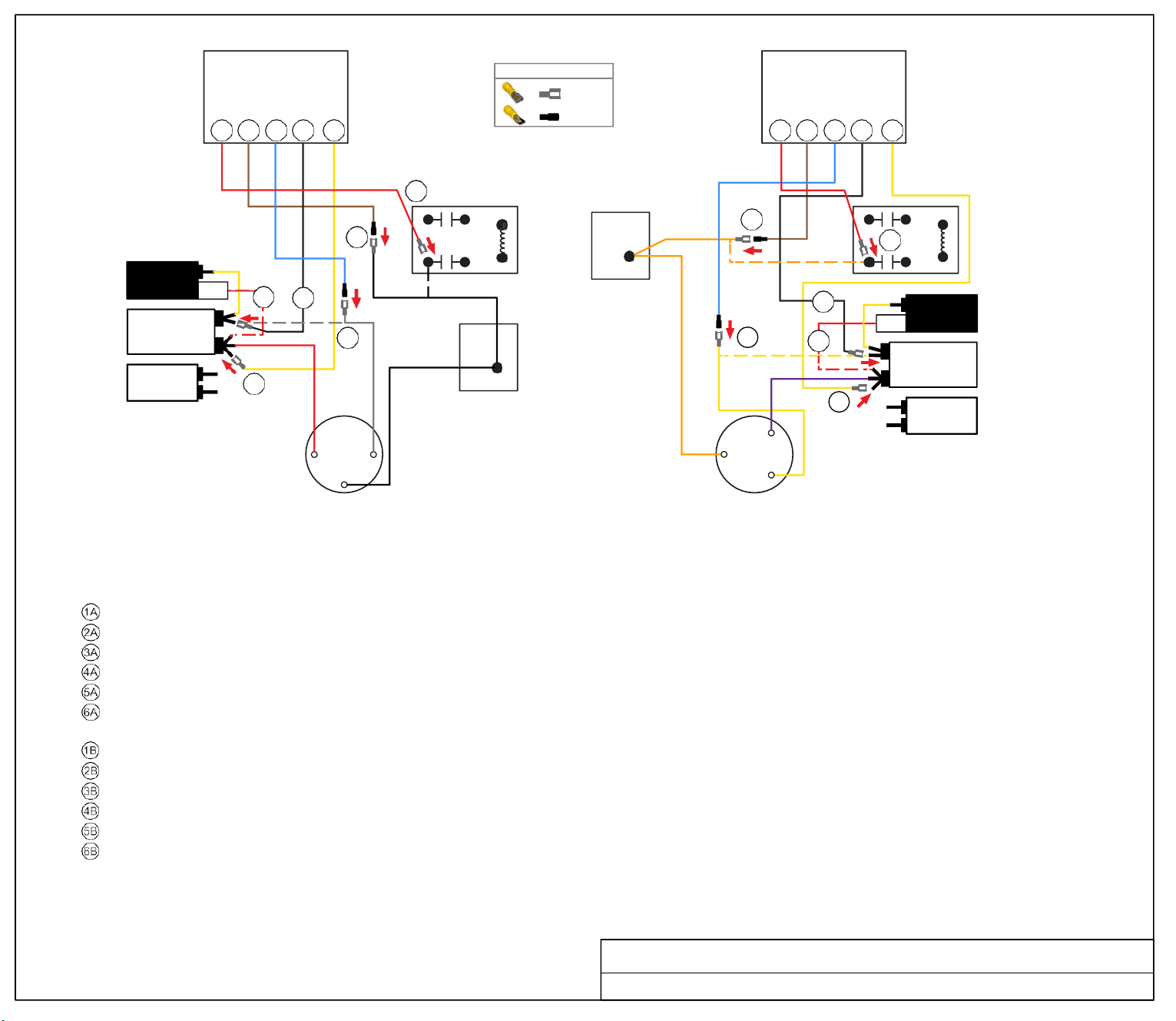
FEMALE
MALE
WIRE CONNECTOR GUIDE
BLACK
C
Soft
Start
Soft
Start
6A 5A 1A 2A 3A
6B 5B
1B 2B 3B
6A
5A
RELAY
5B
6B
RELAY
4A
2A
1A
COMPRESSOR 2
CONTACT
2B
1B
4B
PTCR
C
START
CAPACITOR
RUN
CAPACITOR
3A
COMPRESSOR 1
CONTACT
HERM
3B
B
FAN
S
S
R C
C
R
COMPRESSOR
A
TURN ALL POWER OFF BEFORE STARTING INSTALLATION.
COMPRESSOR
B
Route ALL SoftStart wires into the electrical box. Then crimp Connectors onto all SoftStart wires as indicated in drawing.
NOTE: Instructions are separate for Compressors A and B because wires colors are different. Work with one Compressor and one SoftStart at a time to avoid confusion.
COMPRESSOR A INSTRUCTIONS
Step Follow White Compressor wire to "C" terminal of Run Capacitor. Disconnect and connect to Blue Softstart wire. Tape connection.
Step Connect Black SoftStart wire to the terminal on the Run Capacitor that the White Compressor Wire was on.
Step Connect Yellow SoftStart wire on a terminal next to the Red Compressor wire.
Step Disconnect the PTCR Red wire from the Herm Run Capacitor. Seal end with electrical tape and drop it.
Step Follow Black Compressor wire to the relay. Disconnect and connect to the Brown SoftStart wire. Tape connection.
Step Connect the Red SoftStart wire on the Terminal the Black Compressor wire was on.
COMPRESSOR B INSTRUCTIONS
Step Follow the Yellow Compressor wire to the "C" terminal of the Run Capacitor. Disconnect and connect to the Blue SoftStart wire.
Step Connect Black SoftStart wire to the terminal on the Run Capacitor that the Yellow Compressor wire was on.
Step Connect the Yellow SoftStart wire on a terminal next to the Purple Compressor wire on the Herm terminals.
Step Disconnect the PTCR Red wire from the Herm Run Capacitor. Seal end with electrical tape and drop it.
Step Follow Orange Compressor wire to the relay. Disconnect and connect to the Brown SoftStart wire. Tape connection.
Step Connect the Red SoftStart wire on the terminal that the Orange Compressor wire was on.
Secure all wires. Tape connections with electrical tape.
Turn Power and A/C Breaker on. Turn A/C to Auto Cool setting and set the thermostat to 55ºF.
Look at SoftStart LED lights. Green light should be “on”. Green light means the Compressor is running (there may be a full 3-minute delay before Green light comes on).
IF there is no Green light after 4 minutes, call SoftStart Tech Support for assistance.
After establishing Green light operation, re-install all A/C covers. Turn A/C on, set near
to outdoor temperature and run for 30 minutes. After 30 minutes, operate A/C normally.
Wiring Diagram for Coleman Dual Basement 1976E304 (7-03)
HERM
FAN
RUN
CAPACITOR
A
PTCR
RED
START
CAPACITOR
FEMALE
BROWN
MALE
BLUE
MALE
BLACK
FEMALE
RED
FEMALE
YELLOW
WHITE
RED
ORG
FEMALE
PUR
MALE
BROWN
BLUE
YEL
MALE
BLACK
FEMALE
YELLOW
FEMALE
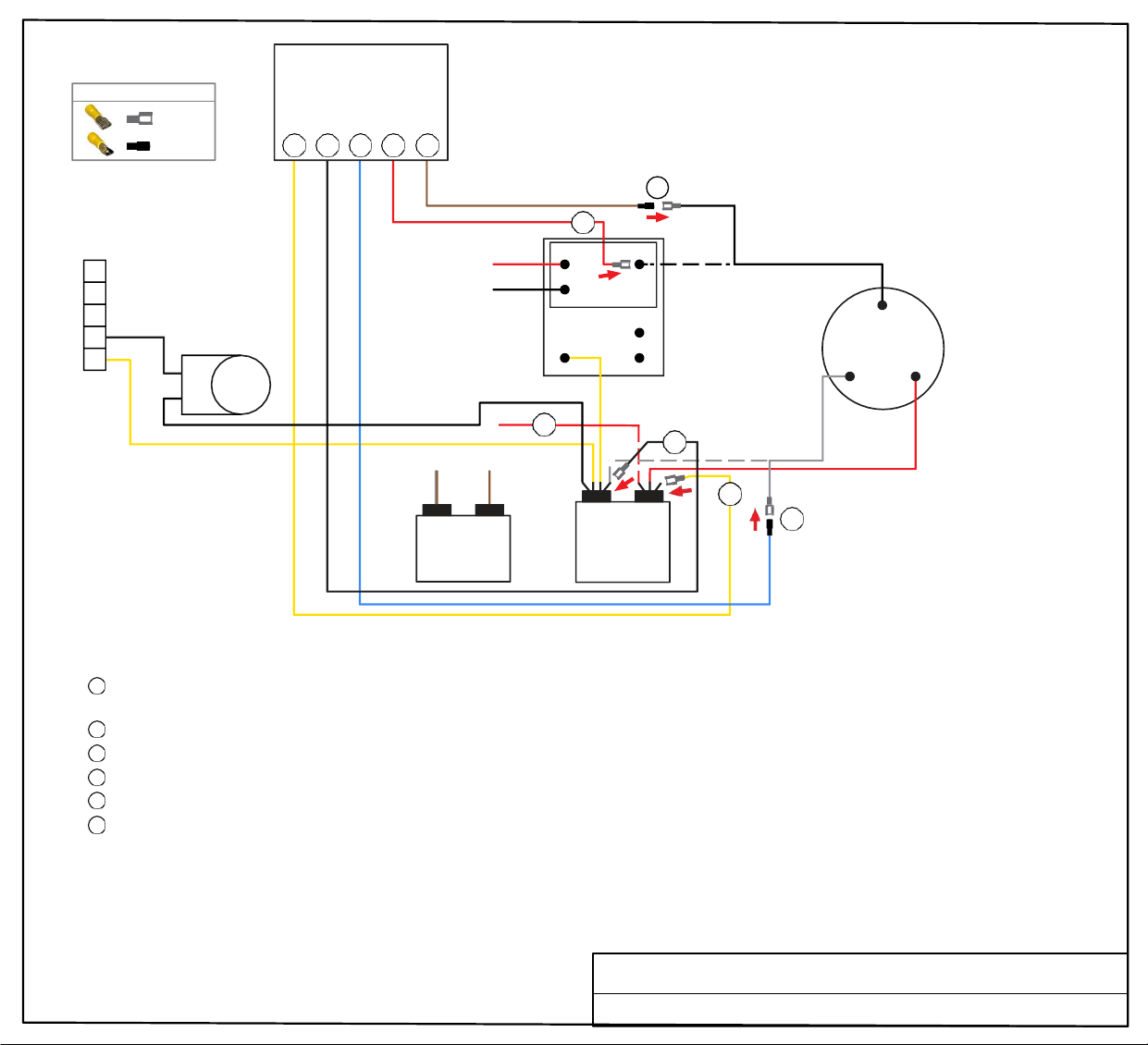
Soft
Start
WIRE CONNECTOR GUIDE
FEMALE
MALE
3 2 1 6 5
5
4
3
2
REVERSING
VALVE
1
5
6
N
C
N
O
COM
OUTDOOR
TEMP
RELAY
BOARD
BLACK
C
R S
COMPRESSOR
4
2
WHITE
FAN
CAPACITOR
3
C HERM
1
RUN
CAPACITOR
RED
TURN ALL POWER OFF BEFORE STARTING INSTALLATION.
Route all SoftStart wires into the electrical box. Then crimp Connectors onto all SoftStart wires as indicated in drawing.
Step
1
Follow White Compressor wire from Compressor to Run Capacitor “C” terminal. Disconnect from “C” terminal and connect it to
Blue SoftStart wire. Tape connection with electrical tape.
Step 2
Step 3
Step
4
Step 5
Step
6
Connect Black SoftStart wire to the terminal that the White Compressor wire was on.
Connect Yellow SoftStart wire on terminal next to Red Compressor wire on HERM terminal of Run Capacitor.
IF there is a second Red wire next to the Red Compressor wire, disconnect it, seal end with tape and drop it.
Follow Black Compressor wire to Outdoor Temperature Relay Board. Disconnect it and connect to Brown SoftStart wire. Tape connection.
Connect Red SoftStart wire onto the terminal that the Black Compressor wire was on.
Secure all wires. Tape connections with electrical tape.
Turn Power and A/C Breaker on. Turn A/C to Auto Cool setting and set the thermostat to 55ºF.
Look at SoftStart LED lights. Green light should be “on”. Green light means the Compressor is running (there may be a full 3-minute delay before
Green light comes on). IF there is no Green light after 4 minutes, call SoftStart Tech Support for assistance.
After establishing Green light operation, re-install all A/C covers.
Turn A/C on, set near to outdoor temperature and run for 30 minutes.
After 30 minutes, operate A/C normally.
YELLOW
Wiring Diagram for Coleman Mach 1976E519 (9-14)
FEMALE
BLACK
FEMALE
BLUE
MALE
RED
FEMALE
BROWN
MALE
BRN/
WHT
BRN
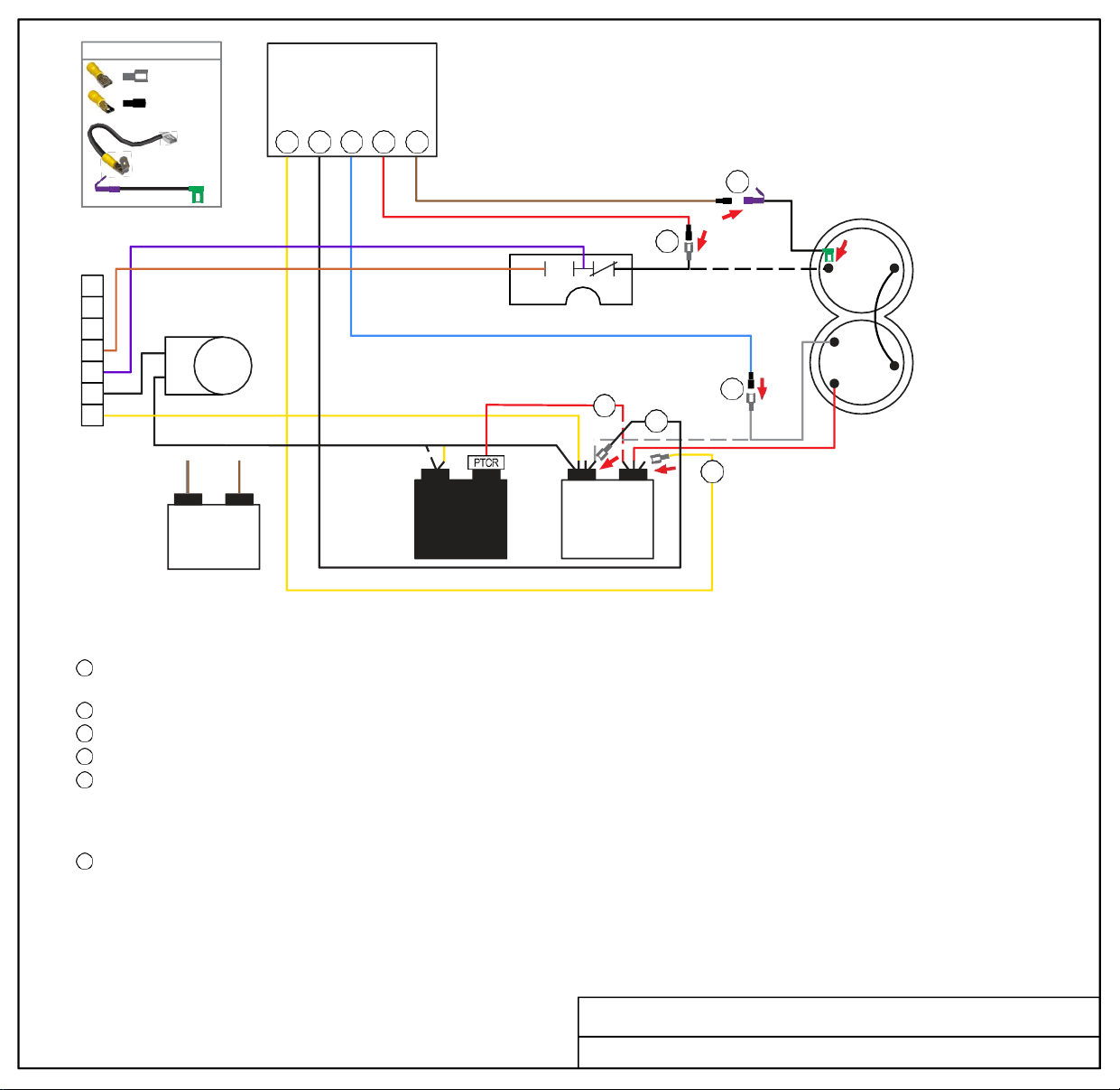
Soft
Start
3 2 1 6 5
5
6
7
6
5
REVERSING
VALVE
4
3
2
BLACK
OUTDOOR FREEZE SWITCH
1
COMPRESSOR
R
C
S
1
FAN
CAPACITOR
START
CAPACITOR
4
2
3
C HERM
RUN
CAPACITOR
WHITE
RED
TURN ALL POWER OFF BEFORE STARTING INSTALLATION.
Route all SoftStart wires into the electrical box. Then crimp Connectors onto all SoftStart wires as indicated in drawing.
Step 1
Step 2
Step 3
Step 4
Step 5
Step 6
Follow White Compressor wire from Compressor to Run Capacitor “C” terminal. Disconnect from “C” terminal and connect it to
Blue SoftStart wire. Seal connection with electrical tape.
Connect Black SoftStart wire to the terminal that the White Compressor wire was on.
Connect Yellow SoftStart wire on terminal next to Red Compressor wire on HERM terminal of Run Capacitor.
IF there is a second Red wire next to the Red Compressor wire, disconnect it, seal end with electrical tape and drop it.
Remove the Compressor Cap. Disconnect Black wire from Overload (OL) terminal. Connect Female Flag end of 4” Pigtail onto the terminal
that the Black Compressor wire was on. Connect Brown SoftStart wire to Female side of Piggyback connector. Break off unused tangent
from Piggyback connector. Tape connection or use heat-shrink sleeve to cover connection (no metal should be exposed). Do not put wires
back under cap. Replace cap.
Connect Red SoftStart wire onto the Black wire end that was connected to the Compressor. Tape connection (no metal should be
exposed).
Secure all wires. Tape connections with electrical tape.
Turn Power and A/C Breaker on. Turn A/C to Auto Cool setting and set the thermostat to 55ºF.
Look at SoftStart LED lights. Green light should be “on”. Green light means the Compressor is running (there may be a full 3-minute delay before
Green light comes on). IF there is no Green light after 4 minutes, call SoftStart Tech Support for assistance.
After establishing Green light operation, re-install all A/C covers.
Turn A/C on, set near to outdoor temperature and run for 30 minutes.
After 30 minutes, operate A/C normally.
Wiring Diagram for Coleman Mach 1976E519 MODIFIED 7-22
FEMALE
MALE
4” PIGTA IL
w/
FEMALE FLAG
& PIGGYBACK
WIRE CONNECTOR GUIDE
BRN/
WHT
BRN
FEMALE
YELLOW
FEMALE
BLACK
MALE
BLUE
MALE
RED
MALE
BROWN
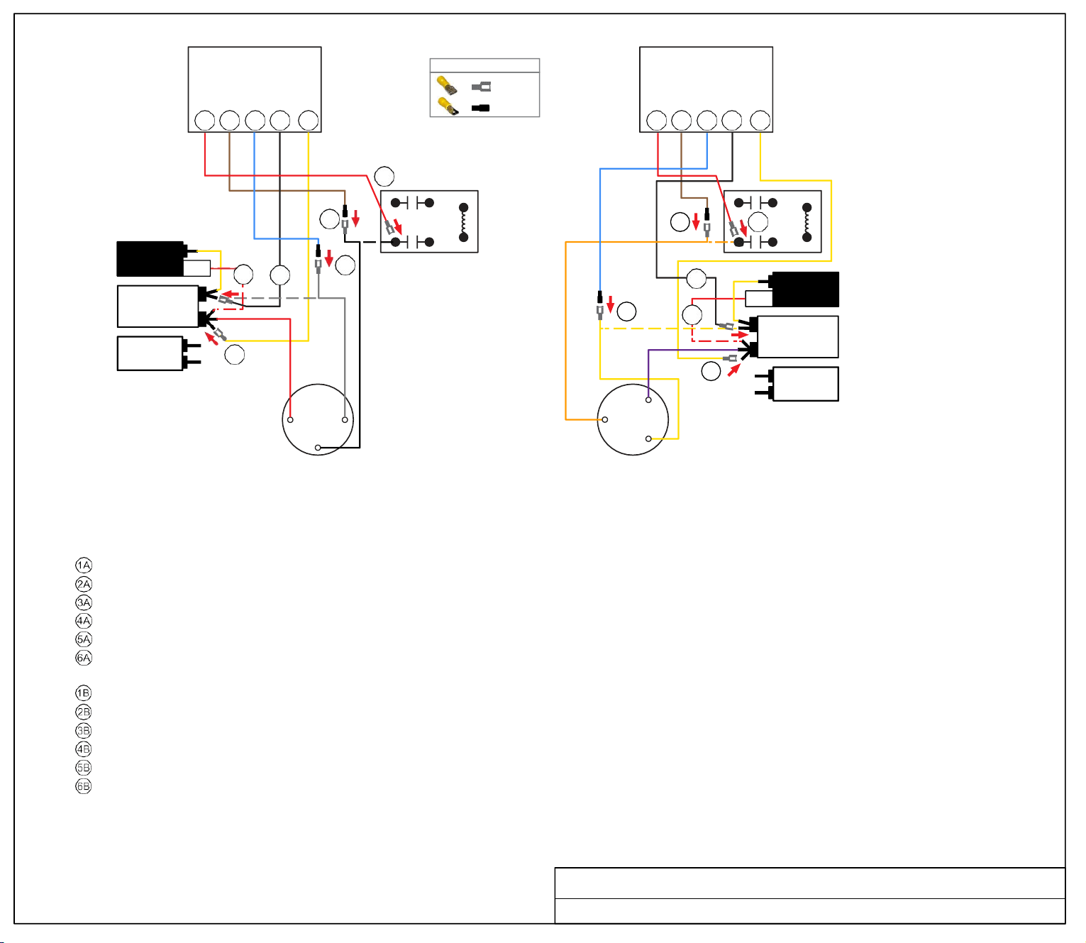
WHITE
BLACK
ORG
PUR
Soft
Start
6B 5B 1B 2B 3B
6A
5A
RELAY
5B 6B
RELAY
1A
4A
2A
2B
1B
4B
PTCR
C
START
CAPACITOR
RUN
CAPACITOR
3A
HERM
B
3B
FAN
S
S
R C
C
R
COMPRESSOR
A
COMPRESSOR
B
TURN ALL POWER OFF BEFORE STARTING INSTALLATION.
Route ALL SoftStart wires into the electrical box. Then crimp Connectors onto all SoftStart wires as indicated in drawing.
NOTE: Instructions are separate for Compressors A and B because wires colors are different. Work with one Compressor and one SoftStart at a time to avoid confusion.
COMPRESSOR A INSTRUCTIONS
Step Follow White Compressor wire to "C" terminal of Run Capacitor. Disconnect and connect to Blue SoftStart wire. Tape connection.
Step Connect Black SoftStart wire to the terminal on the Run Capacitor that the White Compressor Wire was on.
Step Connect Yellow SoftStart wire on a terminal next to the Red Compressor wire.
Step Disconnect the PTCR Red wire from the Herm Run Capacitor. Seal end with electrical tape and drop it.
Step Follow Black compressor wire to the relay. Disconnect and connect to the Brown SoftStart wire. Tape connection.
Step Connect the Red SoftStart wire on the Terminal the Black Compressor wire was on.
COMPRESSOR B INSTRUCTIONS
Step Follow the Yellow Compressor wire to the "C" terminal of the Run Capacitor. Disconnect and connect to the Blue SoftStart wire.
Step Connect Black SoftStart wire to the terminal on the Run Capacitor that the Yellow Compressor wire was on.
Step Connect the Yellow SoftStart wire on a terminal next to the Purple Compressor wire on the Herm terminals.
Step Disconnect the PTCR Red wire from the Herm Run Capacitor. Seal end with electrical tape and drop it.
Step Follow Orange Compressor wire to the relay. Disconnect and connect to the Brown SoftStart wire. Tape connection.
Step Connect the Red SoftStart wire on the terminal that the Orange Compressor wire was on.
Secure all wires. Tape connections with electrical tape.
Turn Power and A/C Breaker on. Turn A/C to Auto Cool setting and set the thermostat to 55ºF.
Look at SoftStart LED lights. Green light should be “on”. Green light means the Compressor is running (there may be a full 3-minute delay before Green light comes on).
IF there is no Green light after 4 minutes, call SoftStart Tech Support for assistance.
After establishing Green light operation, re-install all A/C covers. Turn A/C on, set near
to outdoor temperature and run for 30 minutes. After 30 minutes, operate A/C normally.
Wiring Diagram for Coleman Dual Basement 1976F304 (09-09) Relay
FEMALE
MALE
WIRE CONNECTOR GUIDE
FAN
C
HERM
PTCR
RUN
CAPACITOR
A
6A 5A 1A 2A 3A
START
CAPACITOR
Soft
Start
RED
FEMALE
BROWN
MALE
BLUE
MALE
BLACK
FEMALE
RED
FEMALE
YELLOW
RED
FEMALE
BROWN
MALE
BLUE
YEL
MALE
BLACK
FEMALE
YELLOW
FEMALE
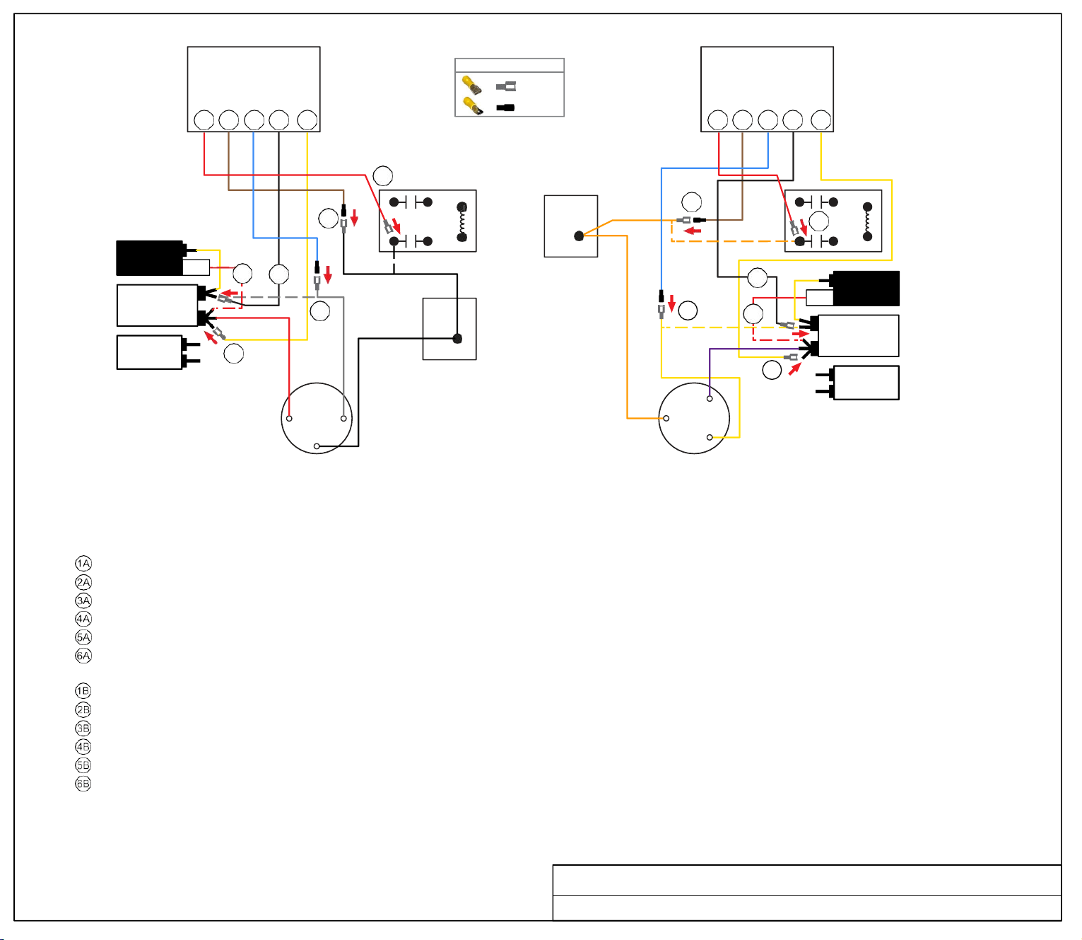
FEMALE
MALE
WIRE CONNECTOR GUIDE
BLACK
C
Soft
Start
Soft
Start
6A 5A 1A 2A 3A
6B 5B
1B 2B 3B
6A
5A
RELAY
5B
6B
RELAY
4A
2A
1A
COMPRESSOR 2
CONTACT
2B
1B
4B
PTCR
C
START
CAPACITOR
RUN
CAPACITOR
3A
COMPRESSOR 1
CONTACT
HERM
3B
B
FAN
S
S
R C
C
R
COMPRESSOR
A
TURN ALL POWER OFF BEFORE STARTING INSTALLATION.
COMPRESSOR
B
Route ALL SoftStart wires into the electrical box. Then crimp Connectors onto all SoftStart wires as indicated in drawing.
NOTE: Instructions are separate for Compressors A and B because wires colors are different. Work with one Compressor and one SoftStart at a time to avoid confusion.
COMPRESSOR A INSTRUCTIONS
Step Follow White Compressor wire to "C" terminal of Run Capacitor. Disconnect and connect to Blue SoftStart wire. Tape connection.
Step Connect Black SoftStart wire to the terminal on the Run Capacitor that the White Compressor Wire was on.
Step Connect Yellow SoftStart wire on a terminal next to the Red Compressor wire.
Step Disconnect the PTCR Red wire from the Herm Run Capacitor. Seal end with electrical tape and drop it.
Step Follow Black Compressor wire to the relay. Disconnect and connect to the Brown SoftStart wire. Tape connection.
Step Connect the Red SoftStart wire on the Terminal the Black Compressor wire was on.
COMPRESSOR B INSTRUCTIONS
Step Follow the Yellow Compressor wire to the "C" terminal of the Run Capacitor. Disconnect and connect to the Blue SoftStart wire.
Step Connect Black SoftStart wire to the terminal on the Run Capacitor that the Yellow Compressor wire was on.
Step Connect the Yellow SoftStart wire on a terminal next to the Purple Compressor wire on the Herm terminals.
Step Disconnect the PTCR Red wire from the Herm Run Capacitor. Seal end with electrical tape and drop it.
Step Follow Orange Compressor wire to the relay. Disconnect and connect to the Brown SoftStart wire. Tape connection.
Step Connect the Red SoftStart wire on the terminal that the Orange Compressor wire was on.
Secure all wires. Tape connections with electrical tape.
Turn Power and A/C Breaker on. Turn A/C to Auto Cool setting and set the thermostat to 55ºF.
Look at SoftStart LED lights. Green light should be “on”. Green light means the Compressor is running (there may be a full 3-minute delay before Green light comes on).
IF there is no Green light after 4 minutes, call SoftStart Tech Support for assistance.
After establishing Green light operation, re-install all A/C covers. Turn A/C on, set near
to outdoor temperature and run for 30 minutes. After 30 minutes, operate A/C normally.
Wiring Diagram for Coleman Dual Basement 1976G304
HERM
FAN
RUN
CAPACITOR
A
PTCR
RED
START
CAPACITOR
FEMALE
BROWN
MALE
BLUE
MALE
BLACK
FEMALE
RED
FEMALE
YELLOW
WHITE
RED
ORG
FEMALE
PUR
MALE
BROWN
BLUE
YEL
MALE
BLACK
FEMALE
YELLOW
FEMALE
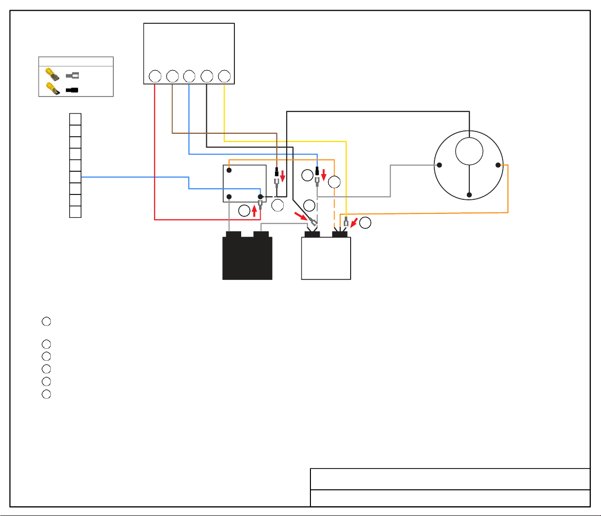
WHITE
2
Soft
Start
WIRE CONNECTOR GUIDE
FEMALE
MALE
6 5 1 2 3
9
8
7
6
5
4
1
RELAY
4
WHITE
BLACK
OL
R S
3
2
1 5
1
6
5
2
WHITE
C
COMPRESSOR
3
ORANGE COMPRESSOR WIRE
START
CAPACITOR
C HERM
RUN
CAPACITOR
TURN ALL POWER OFF BEFORE STARTING INSTALLATION.
Route all SoftStart wires into the electrical box. Then crimp Connectors onto all SoftStart wires as indicated in drawing.
Step
1
Step 2
Step 3
Step 4
Step 5
Step 6
Follow White Compressor wire from Compressor to Run Capacitor “C” terminal. Disconnect from “C” terminal and connect it to
Blue SoftStart wire. Seal connection with electrical tape.
Connect Black SoftStart wire to the terminal that the White Compressor wire was on.
Connect Yellow SoftStart wire on terminal next to Orange Compressor Wire on HERM side of Run Capacitor.
Follow Orange wire from Relay to HERM side of Run Capacitor and disconnect it. Seal end with electrical tape.
Follow Black Compressor wire to Relay. Disconnect Black wire and connect to Brown SoftStart wire. Tape connection.
Connect Red SoftStart wire onto the terminal that the Black Compressor wire was on.
Secure all wires. Tape connections with electrical tape.
Turn Power and A/C Breaker on. Turn A/C to Auto Cool setting and set the thermostat to 55ºF.
Look at SoftStart LED lights. Green light should be “on”. Green light means the Compressor is running (there may be a full 3-minute delay before
Green light comes on). IF there is no Green light after 4 minutes, call SoftStart Tech Support for assistance.
After establishing Green light operation, re-install all A/C covers.
Turn A/C on, set near to outdoor temperature and run for 30 minutes.
After 30 minutes, operate A/C normally.
Wiring Diagram for Coleman Mach N22531
RED
FEMALE
BROWN
MALE
BLUE
MALE
BLACK
FEMALE
YELLOW
FEMALE
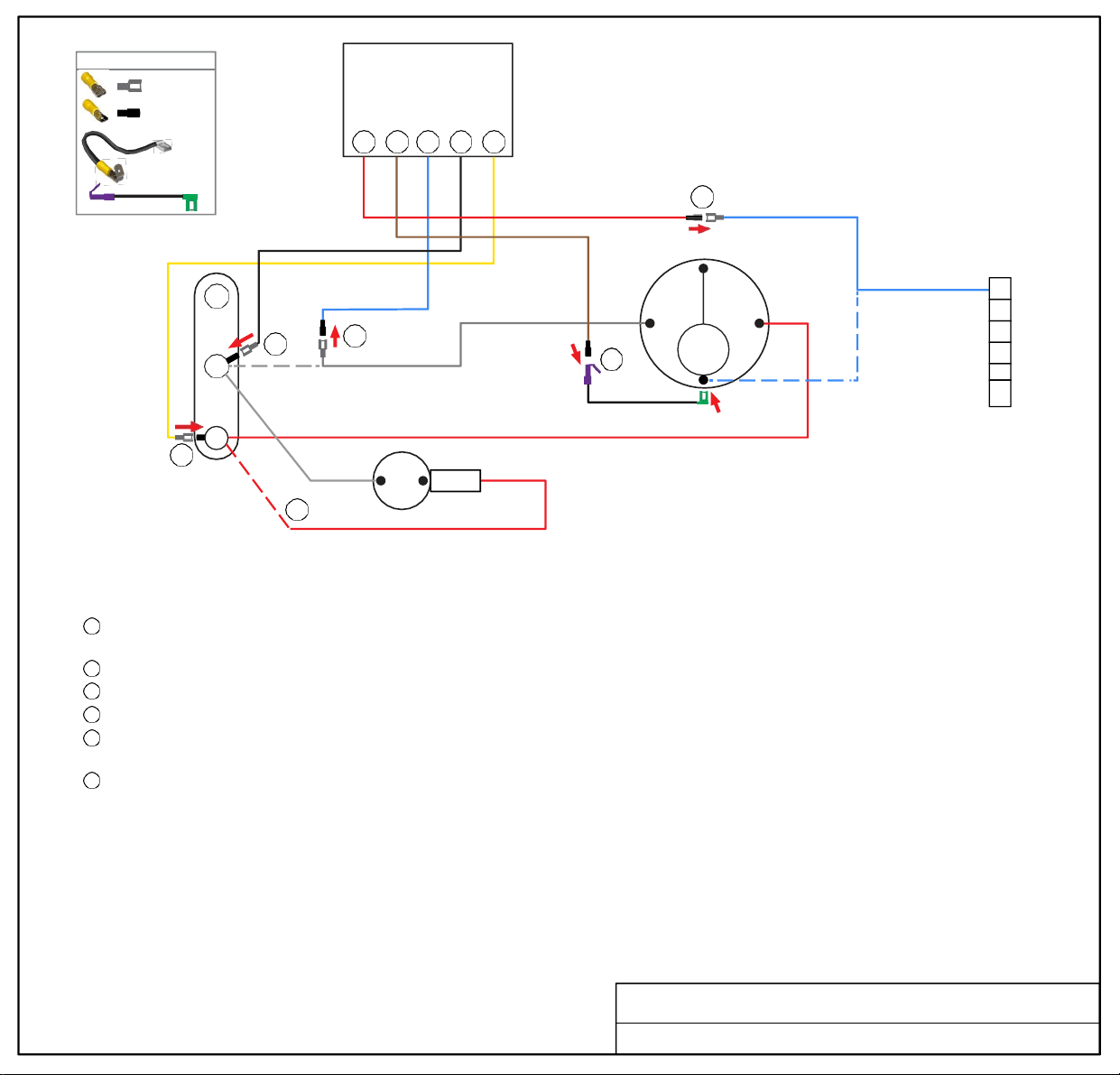
WIRE CONNECTOR GUIDE
FEMALE
Soft
Start
MALE
4” PIGTAIL
w/
FEMALE FLAG
& PIGGYBACK
5 6 1 2 3
5
BLUE COMPRESSOR WIRE
FAN
2
C
HERM
1
WHITE COMPRESSOR WIRE
R
6
4” PIGTAIL
COMPRESSOR
C
S
OL
3
RUN
CAPACITOR
4
PTCR
START
CAPACITOR
RED COMPRESSOR WIRE
TURN OFF ALL POWER BEFORE STARTING INSTALLATION.
Route Blue, Black and Yellow SoftStart wires into the electrical box. Route Brown and Red SoftStart wires to the top of the Compressor.
Crimp Connectors onto all SoftStart wires as indicated in drawing.
Step 1
Step 2
Step
3
Step
4
Step
5
Step
6
Follow White Compressor wire from Compressor to Run Capacitor “C” terminal. Disconnect from “C” terminal and connect it to
Blue SoftStart wire.
Connect Black SoftStart wire to the terminal that the White Compressor wire was on.
Connect Yellow SoftStart wire on terminal next to Red Compressor wire on HERM Side of Run Capacitor.
IF you see a second Red wire next to the Red Compressor wire, disconnect it and seal end with electrical tape.
Remove Compressor cap. Disconnect Blue Compressor wire and connect to Red SoftStart wire. Tape connection.
NOTE: Do not place wires back under the Compressor cap.
Connect Female Flag end of 4” Pigtail onto the terminal that the Blue Compressor wire was on. Connect Brown SoftStart wire to
Female side of Piggyback connector. Break off unused tangent from Piggyback connector. Route Pigtail wire out with Red and
White wires and replace cap.
Secure all wires. Tape connections with electrical tape.
Turn Power and A/C Breaker on. Turn A/C to Auto Cool setting and set the thermostat to 55ºF.
Look at SoftStart LED lights. Green light should be “on”. Green light means the Compressor is running (there may be a full 3-minute delay
before Green light comes on). IF there is no Green light after 4 minutes, call SoftStart Tech Support for assistance.
After establishing Green light operation, re-install all A/C covers.
Turn A/C on, set near to outdoor temperature and run for 30 minutes.
After 30 minutes, operate A/C normally.
Wiring Diagram for All Dometic RV A/Cs
6
5
4
3
2
1
RED
MALE
BROWN
MALE
BLUE
MALE
BLACK
FEMALE
YELLOW
FEMALE
Other Manufacturer
Advent
Advent Air
Atwood
Atwood
Carrier
Carrier
Emerson
Emerson 13.5 Relay
Furrion
Furrion Chill Air 14.5 TB
Houghton-Belaire
Houghton-Belaire A3400-A3401
Relay
Houghton-Belaire 2801 Relay
Houghton-Belaire 2821 Relay
Intertherm
Intertherm SCH-RV A Series
Intertherm ARY-HMR Series
LG
LG MEZ65238817
GE
GE Straight AC
GE AC ARC 13AAC, AHC, 15AAC
GE AC 802021190271 GE AC
CRV-15CBR1-TW+6.PM-4A TB
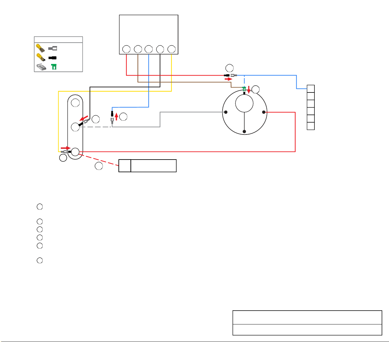
1
2
3
4
5
6
TURN ALL POWER OFF BEFORE STARTING INSTALLATION.
Route Blue, Black and Yellow SoftStart wires into the electrical box. Then crimp Connectors onto all SoftStart wires as indicated in drawing.
Step Follow White Compressor Wire from Compressor to Run Capacitor “C” terminal. Disconnect from “C” terminal and connect it to
Blue SoftStart wire.
Step Connect Black SoftStart wire to the terminal that the White Compressor Wire was on.
Step Connect Yellow SoftStart wire on a terminal next to Red Compressor Wire on "Herm" Side of Run Capacitor.
Step IF you see a second Red wire next to the Red Compressor Wire, disconnect it and seal end with electrical tape.
Step Remove Compressor cap. Disconnect Blue Compressor Wire and connect to Red SoftStart wire. Tape connection.
NOTE: Do not place wires back under the Compressor cap.
Step Crimp Female flag on end of Brown SoftStart wire. Connect Brown SoftStart wire on the Compressor terminal that the Blue wire
was on. Route wire to exit cap with White and Red wires. Replace cap.
Secure all wires. Tape connections with electrical tape.
Turn Power and A/C Breaker on. Turn A/C to Auto Cool setting and the thermostat to 55ºF.
Look at SoftStart LED lights. Green light should be “On” (green light means the Compressor is running).
Green light should turn “Off” during shut down. Re-install all A/C covers. Turn A/C back on and run for 30 minutes.
IF there is no Green light, call SoftStart Tech Support for assistance.
Wiring Diagram for Advent Air Flag NC
Soft
Start
WIRE CONNECTOR GUIDE
FEMALE
5 6 1 2 3
MALE
FEMA LE
FLAG
5
BLUE COMPRESSOR WIRE
6
OL
FAN
R
S
2
1
WHITE COMPRESSOR WIRE
C
1
2
3
4
5
6
C
COMPRESSOR
HERM
DO NOT REMOVE
RED COMPRESSOR WIRE
3
RUN
CAPACITOR
4
START
CAPACITOR
PTCR
RED
MALE
BROWN
FEMALE
FLAG
BLUE
MALE
BLACK
FEMALE
YELLOW
FEMALE
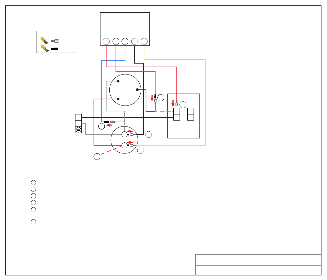
Soft
Start
WIRE CONNECTOR GUIDE
FEMALE
MALE
6 5 1 2 3
R
COMPRESSOR
C
S
5
6
L
BLACK
N
WHITE
WHITE
1
C
BLACK
2
COM
LINE
CIRCUIT
BOARD
HERM 3
4
RUN
CAPACITOR
TURN ALL POWER OFF BEFORE STARTING INSTALLATION.
Route ALL SoftStart wires into the electrical box. Then crimp Connectors onto all SoftStart wires as indicated in drawing.
Step
1
Step
2
Step
3
Step
4
Step 5
Step
6
Follow White Compressor wire to Run Capacitor “C” terminal. Disconnect from “C” terminal and connect it to Blue SoftStart wire.
Connect Black SoftStart wire to the terminal that the White Compressor Wire was on.
Connect Yellow SoftStart wire on terminal next to Red Compressor Wire on "Herm" Side of Run Capacitor.
IF you see a second Red wire next to the Red Compressor Wire, disconnect it and seal end with electrical tape.
Follow Black Compressor wire to Circuit Board COM port terminal. Disconnect wire from COM terminal and connect to
Brown SoftStart wire.
Connect Red SoftStart wire to COM terminal onto the terminal that the Black Compressor Wire was on.
Secure all wires to prevent fan from pulling wires in. Tape connections with electrical tape.
Turn Power and A/C Breaker on. Turn A/C to Auto Cool setting and set the thermostat to 55ºF.
Look at SoftStart LED lights. Green light should be “on”. Green light means the Compressor is running (there may be a full 3-minute delay
before Green light comes on). IF there is no Green light after 4 minutes, call SoftStart Tech Support for assistance.
After establishing Green light operation, re-install all A/C covers. Turn A/C on,
set near to outdoor temperature and run for 30 minutes. After 30 minutes,
operate A/C normally.
Wiring Diagram for Atwood AC w/ CB
RED
FEMALE
BROWN
MALE
BLUE
MALE
BLACK
FEMALE
YELLOW
FEMALE
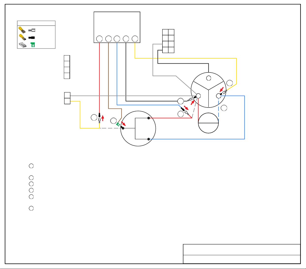
Soft
Start
4P
2P
2
1
5
YELLOW
6
C
COMPRESSOR
WHITE
WHITE
2
RED
1
R
S
BLUE
C
PTCR
RUN
CAPACITOR
F
3
H
4
DISCONNECT
START
CAPACITOR
TURN ALL POWER OFF BEFORE STARTING INSTALLATION.
Route ALL SoftStart wires into the electrical box. Then crimp Connectors onto all SoftStart wires as indicated in drawing.
Step 1
Step 2
Step 3
Step 4
Step 5
Step 6
Follow Red Compressor wire from Compressor to Run Capacitor “C” terminal. Disconnect from “C” terminal and connect it to Blue
SoftStart wire.
Connect Black SoftStart wire to the terminal that the Red Compressor wire was on.
Connect Yellow SoftStart wire on a terminal next to Blue Compressor Wire on "H” Herm terminal of Run Capacitor.
Disconnect Blue Start Capacitor wire next to Blue Compressor wire on "H" Herm terminal. Seal end with electrical tape and drop it.
Remove Compressor cap. Disconnect Yellow Compressor Wire and connect to Red SoftStart wire. Tape connection.
NOTE: Do not place wires back under the Compressor cap.
Crimp Female flag on end of Brown SoftStart wire. Connect Brown SoftStart wire on the Compressor terminal that the Yellow wire
was on. Route Brown wire to exit cap with Red and Blue wires. Replace cap.
Secure all wires to prevent fan from pulling wires into it. Tape connections with electrical tape.
Turn Power and A/C Breaker on. Turn A/C to Auto Cool setting and the thermostat to 55ºF.
Look at SoftStart LED lights. Green light should be “On” (green light means the Compressor is running). It may take 3 minutes
before Green light turns “On.”
Green light should turn “Off” during shut down. Re-install all A/C covers.
Turn A/C back on and run for 30 minutes.
IF there is no Green light, call SoftStart Tech Support for assistance.
Wiring Diagram for Carrier RV Air Conditioner
2
2
1
1
FEMALE
MALE
FEMA LE FLAG
WIRE CONNECTOR GUIDE
4
4
3
3
5 6 1 2 3
RED
MALE
BROWN
FEMA LE
FLAG
BLUE
MALE
BLACK
FEMALE
YELLOW
FEMALE
1
2
3
4
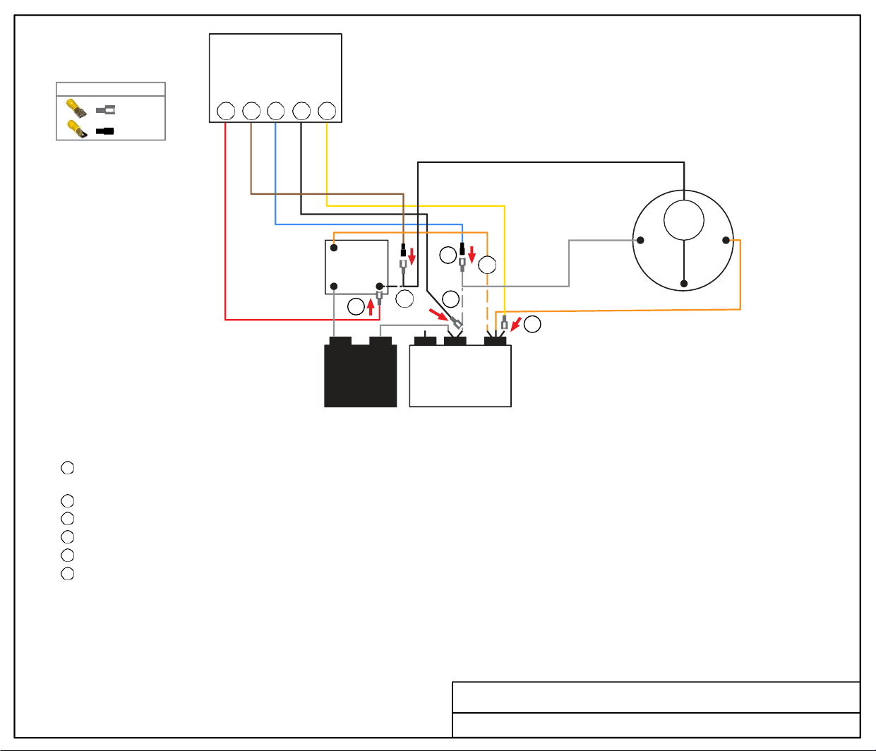
Soft
Start
6 5 1 2 3
BLACK
2
1
RELAY
4
1 5
6
5 2
WHITE
OL
R S
C
COMPRESSOR
WHITE
3
ORANGE COMPRESSOR WIRE
START
CAPACITOR
FAN
C HERM
RUN
CAPACITOR
TURN ALL POWER OFF BEFORE STARTING INSTALLATION.
Route all SoftStart wires into the electrical box. Then crimp Connectors onto all SoftStart wires as indicated in drawing.
Step
1
Step 2
Step 3
Step 4
Step 5
Step 6
Follow White Compressor wire from Compressor to Run Capacitor “C” terminal. Disconnect from “C” terminal and connect it to
Blue SoftStart wire. Seal connection with electrical tape.
Connect Black SoftStart wire to the terminal that the White Compressor wire was on.
Connect Yellow SoftStart wire on terminal next to Orange Compressor wire on HERM side of Run Capacitor.
Follow Orange wire from Relay to HERM side of Run Capacitor and disconnect it. Seal end with electrical tape.
Follow Black Compressor wire to Relay. Disconnect Black wire and connect to Brown SoftStart wire. Tape connection.
Connect Red SoftStart wire onto the terminal that the Black Compressor wire was on.
Secure all wires. Tape connections with electrical tape.
Turn Power and A/C Breaker on. Turn A/C to Auto Cool setting and set the thermostat to 55ºF.
Look at SoftStart LED lights. Green light should be “on”. Green light means the Compressor is running (there may be a full 3-minute delay before
Green light comes on). IF there is no Green light after 4 minutes, call SoftStart Tech Support for assistance.
After establishing Green light operation, re-install all A/C covers.
Turn A/C on, set near to outdoor temperature and run for 30 minutes.
After 30 minutes, operate A/C normally.
Wiring Diagram for Emerson 13.5 Relay
FEMALE
MALE
WIRE CONNECTOR GUIDE
RED
FEMALE
BROWN
MALE
BLUE
MALE
BLACK
FEMALE
WHITE
YELLOW
FEMALE
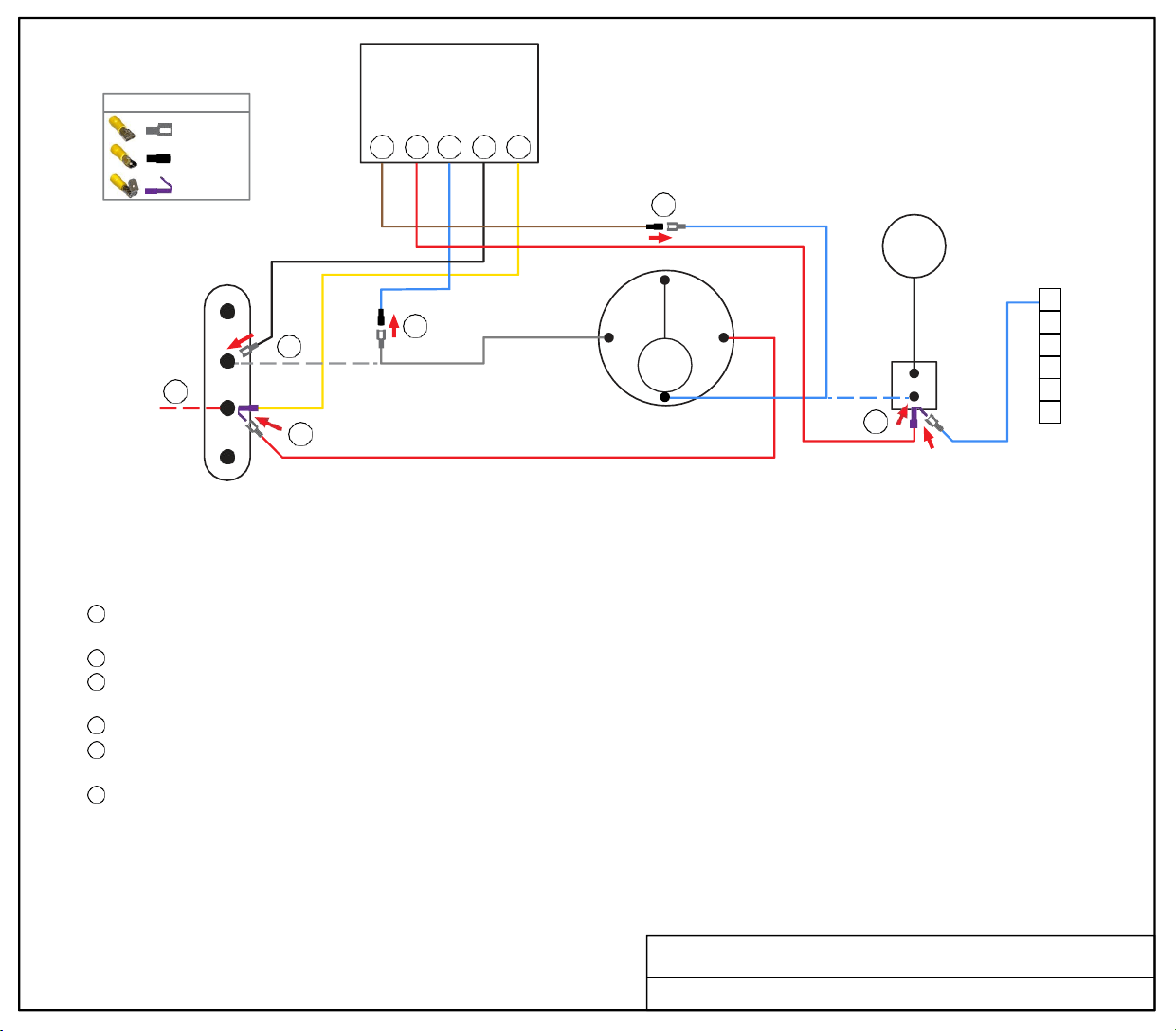
Soft
Start
WIRE CONNECTOR GUIDE
FEMALE
MALE
PIGGYBACK
5 6 1 2 3
5
BLUE COMPRESSOR WIRE
IF
2
COM
4
CP
OF
3
1
WHITE COMPRESSOR WIRE
COMPRESSOR
C
R S
OL
OUTDOOR
MOTOR
6
RUN
CAPACITOR
RED COMPRESSOR WIRE
TERMINAL
BLOCK
TURN ALL POWER OFF BEFORE STARTING INSTALLATION.
Route Blue, Black and Yellow SoftStart wires into the electrical box. Route Brown and Red SoftStart wires to the top of the Compressor.
Crimp Connectors onto all SoftStart wires as indicated in drawing.
Step
1
Step 2
Step 3
Step
4
Step
5
Step
6
Follow White Compressor wire from Compressor to Run Capacitor COM terminal. Disconnect from COM terminal and connect it to
Blue SoftStart wire.
Connect Black SoftStart wire to the terminal that the White Compressor wire was on.
Disconnect the Red Compressor wire. Connect Yellow SoftStart wire on terminal that the Red wire was on. Reconnect the Red
Compressor wire onto the Piggyback connector of the Yellow SoftStart wire.
IF you see a second Red wire next to the Red Compressor wire, disconnect it and seal end with electrical tape.
Follow the Blue Compressor wire to the terminal block. Disconnect it from the terminal block and connect it to the
Brown SoftStart wire. Seal connection with electrical tape.
Connect Red SoftStart wire onto the terminal that the Blue Compressor wire was on. Connect Blue wire from 6-pin connector to
Piggyback connector of Red SoftStart wire.
Secure all wires. Tape connections with electrical tape.
Turn Power and A/C Breaker on. Turn A/C to Auto Cool setting and set the thermostat to 55ºF.
Look at SoftStart LED lights. Green light should be “on”. Green light means the Compressor is running (there may be a full 3-minute delay
before Green light comes on). IF there is no Green light after 4 minutes, call SoftStart Tech Support for assistance.
After establishing Green light operation, re-install all A/C covers.
Turn A/C on, set near to outdoor temperature and run for 30 minutes.
After 30 minutes, operate A/C normally.
Wiring Diagram for Furrion Chill Air 14.5 TB
BROWN
MALE
RED
PIGGYBACK
BLUE
MALE
BLACK
FEMALE
YELLOW
PIGGYBACK
1
2
3
4
5
6
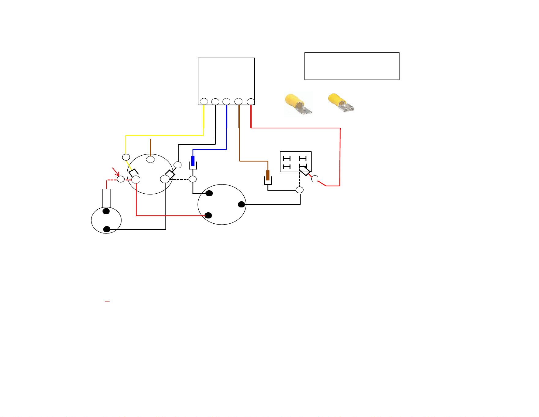
2 Req
3 Req
male
Female
Terminal
Block
3
Disconnect
2nd red
Fan
2
4
C
6
Herm
1
Wht
R
5
C
Black
Red
S
White
3
2 1
5
6
Softstart
GE Straight AC
820201190271
Turn All Power and Breakers OFF before beginning Install
Route ALL softstart wires into electrical box first, then Crimp disconnects as shown in softstart drawing above
Step 1) Follow white compressor wire to "C" terminal on RUN capacitor, Disconnect and connect to Blue Softstart wire.
Step 2) Connect Black Softstart wire on terminal White wire was on.
Step 3) Connect Yellow Softstart wire on a terminal next to Red Compressor wire on HERM side of RUN capacitor.
Step 4) IF you see a 2nd red wire next to Red compressor wire Disconnect and tape end.
Step 5) Follow Black compressor wire to Terminal block, Disconnect and connect to Brown Softstart wire.
Step 6) Connect Red Softstart wire on terminal Block black wire was on.
Secure all wires
Turn power and AC breaker on, Turn fan on hi 1 min., Turn AC to auto cool set Tstat to 55.
Go look at softstart you should have a green light ( you may have a 3 min delay before light turn green) IF after 3 full min no green light call me.
Green light on, Turn ac off tape #1 & 5 connections, replace all covers the turn ac back on and rum for 3 min.
PTC
Brow
Red
Yellow
Black
Female
Male
Male
Female
Blue
Brown
Red
Female
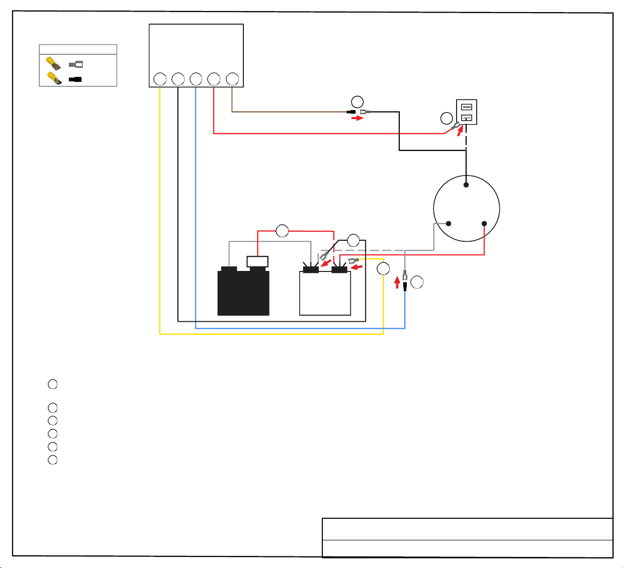
PTCR
Soft
Start
3 2 1 6 5
TERMINAL
BLOCK
5
6
BLACK
C
COMPRESSOR
4
2
WHITE
3
1
R S
RED
TURN ALL POWER OFF BEFORE STARTING INSTALLATION.
Route all SoftStart wires into the electrical box. Then crimp Connectors onto all SoftStart wires as indicated in drawing.
Step
1
Follow White Compressor wire from Compressor to Run Capacitor “C” terminal. Disconnect from “C” terminal and connect it to Blue
SoftStart wire. Tape connection with electrical tape.
Step 2
Step 3
Step
4
Step 5
Step
6
Connect Black SoftStart wire to the terminal that the White Compressor wire was on.
Connect Yellow SoftStart wire on terminal next to Red Compressor wire on HERM terminal of Run Capacitor.
IF there is a second Red wire next to the Red Compressor wire, disconnect it, seal end with tape and drop it.
Follow Black Compressor wire to Terminal Block. Disconnect it and connect to Brown SoftStart wire. Tape connection.
Connect Red SoftStart wire onto the terminal that the Black Compressor wire was on.
Secure all wires. Tape connections with electrical tape.
Turn Power and A/C Breaker on. Turn A/C to Auto Cool setting and set the thermostat to 55ºF.
Look at SoftStart LED lights. Green light should be “on”. Green light means the Compressor is running (there may be a full 3-minute delay before
Green light comes on). IF there is no Green light after 4 minutes, call SoftStart Tech Support for assistance.
After establishing Green light operation, re-install all A/C covers.
Turn A/C on, set near to outdoor temperature and run for 30 minutes.
After 30 minutes, operate A/C normally.
FEMALE
MALE
WIRE CONNECTOR GUIDE
C HERM
RUN
CAPACITOR
Wiring Diagram for GE AC ARC 13AAC, AHC, 15AAC
YELLOW
START
CAPACITOR
FEMALE
BLACK
FEMALE
BLUE
MALE
RED
FEMALE
BROWN
MALE
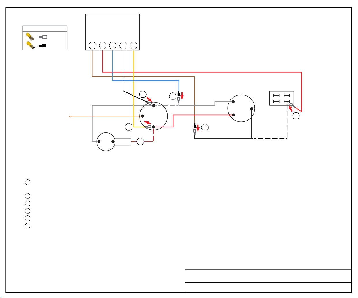
Soft
Start
5 6 1 2 3
BROWN
WHITE
2
FAN
3
1
C
RUN
CAPACITOR
HERM
WHITE
5
R
C
S
COMPRESSOR
TERMINAL
BLOCK
6
PTCR 4
BLACK
START
CAPACITOR
TURN ALL POWER OFF BEFORE STARTING INSTALLATION.
Route all SoftStart wires into the electrical box. Crimp Connectors onto all SoftStart wires as indicated in drawing.
Step 1
Step 2
Step 3
Step 4
Step 5
Step 6
Follow White Compressor wire to “C” terminal on Run Capacitor. Disconnect from terminal and connect it to Blue SoftStart wire.
Seal connection with electrical tape.
Connect Black SoftStart wire to the terminal that the White Compressor wire was on.
Connect Yellow SoftStart wire on terminal next to Red Compressor wire on HERM side of Run Capacitor.
IF there is a second Red wire next to Red Compressor wire on HERM side of Run Capacitor, disconnect it, seal end with tape and drop it.
Follow Black Compressor wire to the Terminal Block. Disconnect Black wire from Terminal Block and connect to Brown SoftStart wire.
Connect Red SoftStart wire onto the terminal that the Black Compressor wire was on.
Secure all wires. Tape connections with electrical tape.
Turn Power and A/C Breaker on. Turn A/C to Auto Cool setting and the thermostat to 55ºF.
Look at SoftStart LED lights. Green light should be “on”. Green light means the Compressor is running (there may be a full 3-minute delay before
Green light comes on). IF there is no Green light after 4 minutes, call SoftStart Tech Support for assistance.
Re-install all A/C covers. Turn A/C on, set near to outdoor temperature and run for 30 minutes.
After 30 minutes, operate A/C normally.
SoftStartRV Wiring Diagram for GE AC 802021190271 TB
FEMALE
MALE
WIRE CONNECTOR GUIDE
BROWN
MALE
RED
FEMALE
BLUE
MALE
BLACK
FEMALE
YELLOW
FEMALE
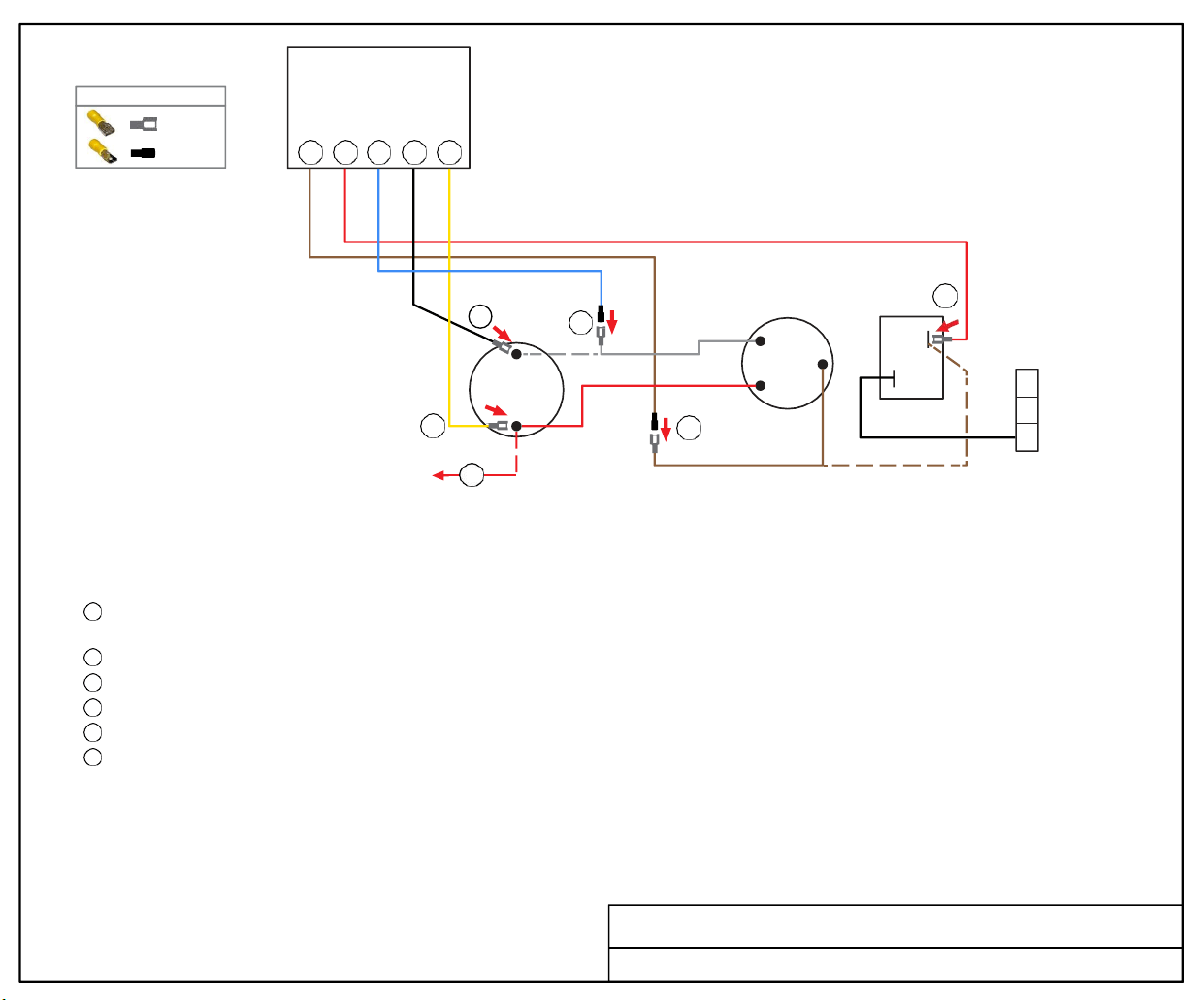
SoftStartRV
5 6 1 2 3
2
1
C
RUN
CAPACITOR
HERM
3
WHITE
5
R
C
S
COMPRESSOR
6
COMP
LIVE
G
RELAY
N
L
4
BROWN
TURN ALL POWER OFF BEFORE STARTING INSTALLATION.
Route all SoftStart wires into the electrical box. Crimp Connectors onto all SoftStart wires as indicated in drawing.
Step 1
Step 2
Step 3
Step 4
Step 5
Step 6
Follow White Compressor wire to “C” terminal on Run Capacitor. Disconnect from terminal and connect it to Blue SoftStart wire.
Seal connection with electrical tape.
Connect Black SoftStart wire to the terminal that the White Compressor wire was on.
Connect Yellow SoftStart wire on terminal next to Red Compressor wire on HERM side of Run Capacitor.
IF there is a second Red wire next to Red Compressor wire on HERM side of Run Capacitor, disconnect it, seal end with tape and drop it.
Follow Brown Compressor wire to the COMP Relay. Disconnect Brown wire from Relay and connect to Brown SoftStart wire.
Connect Red SoftStart wire onto the terminal that the Brown Compressor wire was on.
Secure all wires. Tape connections with electrical tape.
Turn Power and A/C Breaker on. Turn A/C to Auto Cool setting and the thermostat to 55ºF.
Look at SoftStart LED lights. Green light should be “on”. Green light means the Compressor is running (there may be a full 3-minute delay before
Green light comes on). IF there is no Green light after 4 minutes, call SoftStart Tech Support for assistance.
Re-install all A/C covers. Turn A/C on, set near to outdoor temperature and run for 30 minutes.
After 30 minutes, operate A/C normally.
SoftStartRV Wiring Diagram for Houghton-Belaire A3400-A3401 Relay
Copyright © MMXXII NetworkRV LLC. All Rights Reserved.
FEMALE
MALE
WIRE CONNECTOR GUIDE
BROWN
MALE
RED
FEMALE
BLUE
MALE
BLACK
FEMALE
YELLOW
FEMALE
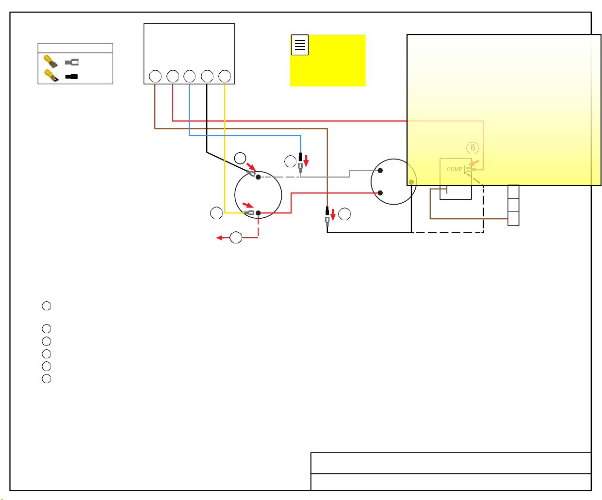
Soft
Start
5 6 1 2 3
2
1
C
RUN
CAPACITOR
HERM
3
WHITE
5
R
C
S
COMPRESSOR
6
COMP
LIVE
G
RELAY
N
L
4
BLACK
TURN ALL POWER OFF BEFORE STARTING INSTALLATION.
Route all SoftStart wires into the electrical box. Crimp Connectors onto all SoftStart wires as indicated in drawing.
Step 1
Step 2
Step 3
Step 4
Step 5
Step 6
Follow White Compressor wire to “C” terminal on Run Capacitor. Disconnect from terminal and connect it to Blue SoftStart wire.
Seal connection with electrical tape.
Connect Black SoftStart wire to the terminal that the White Compressor wire was on.
Connect Yellow SoftStart wire on terminal next to Red Compressor wire on HERM side of Run Capacitor.
IF there is a second Red wire next to Red Compressor wire on HERM side of Run Capacitor, disconnect it, seal end with tape and drop it.
Follow Black Compressor wire to the COMP Relay. Disconnect Black wire from Relay and connect to Brown SoftStart wire.
Connect Red SoftStart wire onto the terminal that the Black Compressor wire was on.
Secure all wires. Tape connections with electrical tape.
Turn Power and A/C Breaker on. Turn A/C to Auto Cool setting and the thermostat to 55ºF.
Look at SoftStart LED lights. Green light should be “on”. Green light means the Compressor is running (there may be a full 3-minute delay before
Green light comes on). IF there is no Green light after 4 minutes, call SoftStart Tech Support for assistance.
Re-install all A/C covers. Turn A/C on, set near to outdoor temperature and run for 30 minutes.
After 30 minutes, operate A/C normally.
Wiring Diagram for Houghton-Belaire 2801 Relay
FEMALE
MALE
WIRE CONNECTOR GUIDE
BROWN
MALE
RED
FEMALE
BLUE
MALE
BLACK
FEMALE
YELLOW
FEMALE
PA Snyder
2022-03-13 11:58:00
--------------------------------------------
This is updated 3-13-22 to show the
correct wire colors. See the dates of
the new docs to verify all is up-to-date,
then update diagram on SoftStartRV
support pages, please.
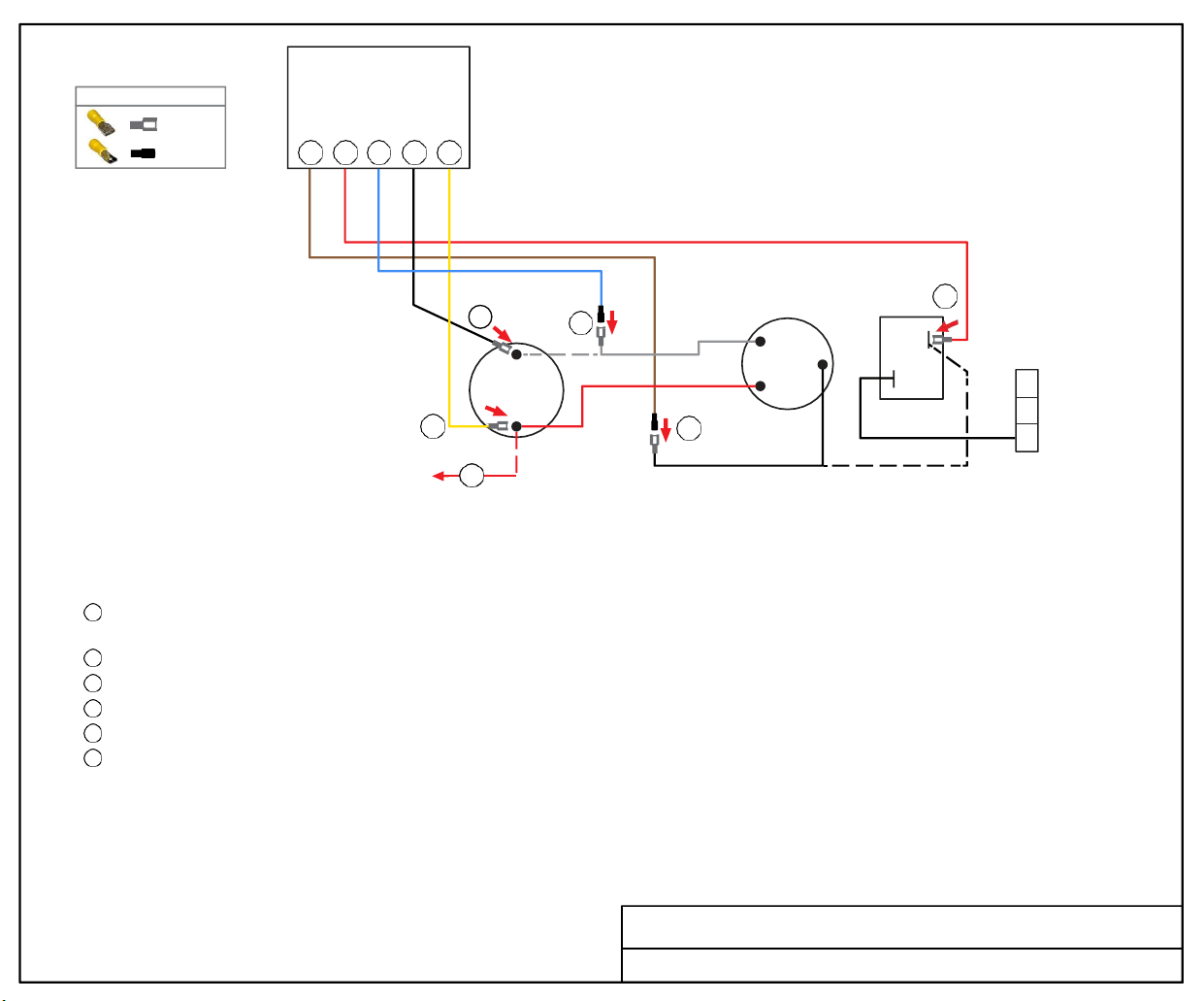
Soft
Start
5 6 1 2 3
2
1
C
RUN
CAPACITOR
HERM
3
WHITE
5
R
C
S
COMPRESSOR
6
COMP
LIVE
G
RELAY
N
L
4
BLACK
TURN ALL POWER OFF BEFORE STARTING INSTALLATION.
Route all SoftStart wires into the electrical box. Crimp Connectors onto all SoftStart wires as indicated in drawing.
Step 1
Step 2
Step 3
Step 4
Step 5
Step 6
Follow White Compressor wire to “C” terminal on Run Capacitor. Disconnect from terminal and connect it to Blue SoftStart wire.
Seal connection with electrical tape.
Connect Black SoftStart wire to the terminal that the White Compressor wire was on.
Connect Yellow SoftStart wire on terminal next to Red Compressor wire on HERM side of Run Capacitor.
IF there is a second Red wire next to Red Compressor wire on HERM side of Run Capacitor, disconnect it, seal end with tape and drop it.
Follow Black Compressor wire to the COMP Relay. Disconnect Black wire from Relay and connect to Brown SoftStart wire.
Connect Red SoftStart wire onto the terminal that the Black Compressor wire was on.
Secure all wires. Tape connections with electrical tape.
Turn Power and A/C Breaker on. Turn A/C to Auto Cool setting and the thermostat to 55ºF.
Look at SoftStart LED lights. Green light should be “on”. Green light means the Compressor is running (there may be a full 3-minute delay before
Green light comes on). IF there is no Green light after 4 minutes, call SoftStart Tech Support for assistance.
Re-install all A/C covers. Turn A/C on, set near to outdoor temperature and run for 30 minutes.
After 30 minutes, operate A/C normally.
Wiring Diagram for Houghton-Belaire 2821 Relay
FEMALE
MALE
WIRE CONNECTOR GUIDE
BROWN
MALE
RED
FEMALE
BLUE
MALE
BLACK
FEMALE
YELLOW
FEMALE
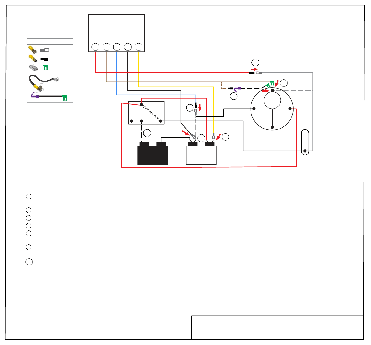
WIRE CONNECTOR GUIDE
OR
Soft
Start
5 6 1 2 3
5
WHITE COMPRESSOR WIRE
6
2
RELAY
6 1
5
4
BLACK
1
2
3
C HERM
6P
BLACK
OL
R
C
COMPRESSOR
S
WHITE
START
CAPACITOR
TURN ALL POWER OFF BEFORE STARTING INSTALLATION.
RUN
CAPACITOR
RED COMPRESSOR WIRE
MOTOR
CAPACITOR
RouteBlue, Black and Yellow SoftStart wires into the electrical box. Route Red and Brown SoftStart wires to the Compressor.
Then crimp Connectors onto all SoftStart wires as indicated in drawing.
Step
1
Step
2
Step
3
Step
4
Step
5
Step
6
Follow Black Compressor wire from Compressor to Run Capacitor “C” terminal. Disconnect from “C” terminal and connect it to
Blue SoftStart wire. Seal connection with electrical tape.
Connect Black SoftStart wire to the terminal that the Black Compressor wire was on.
Connect Yellow SoftStart wire on terminal next to Red Compressor Wire on HERM side of Run Capacitor.
Disconnect the Black Start Capacitor wire from the Relay. Seal end with electrical tape.
Remove Compressor cap. Disconnect White Compressor wire and connect to Red SoftStart wire. Tape connection.
NOTE: Do not place wires back under the Compressor cap.
Connect Brown SoftStart wire onto the terminal that the White Compressor wire was on. Route Pigtail wire out with Red and White wires
and replace cap.
Step 6P [OPTIONAL] Connect Female Flag end of 4” PigTail onto the terminal that the White Compressor wire was on. Crimp Male
connector onto Brown SoftStart wire, then connect it to Female side of Piggyback connector. Break off unused tangent from Piggyback
connector. Route Pigtail wire out with Red and White wires and replace cap.
Secure all wires. Tape connections with electrical tape.
Turn Power and A/C Breaker on. Turn A/C to Auto Cool setting and set the thermostat to 55ºF.
Look at SoftStart LED lights. Green light should be “on”. Green light means the Compressor is running (there may be a full 3-minute delay before
Green light comes on). IF there is no Green light after 4 minutes, call
SoftStart Tech Support for assistance.
After establishing Green light operation, re-install all A/C covers.
Turn A/C on, set near to outdoor temperature and run for 30 minutes.
After 30 minutes, operate A/C normally.
4” PIGTA IL
w/
FEMALE FLAG
& PIGGYBACK
Wiring Diagram for Intertherm SCH-RV A Series
FEMALE
MALE
FEMA LE FLAG
RED
MALE
BROWN
FEMALE
FLAG
BLUE
MALE
BLACK
FEMALE
YELLOW
FEMALE
BLACK
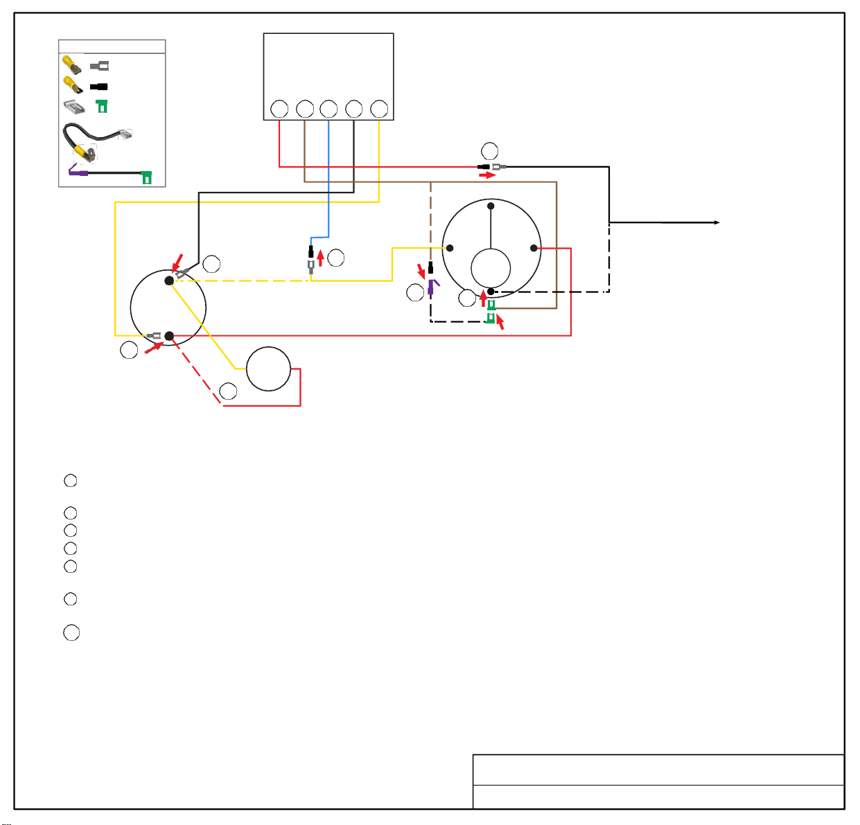
WIRE CONNECTOR GUIDE
FEMALE
Soft
Start
MALE
FEMALE
FLAG
OR
4” PIGTAIL
w/
FEMALE FLAG
& PIGGYBACK
5 6 1 2 3
5
BLACK COMPRESSOR WIRE
COMPRESSOR
C
TO COOLING CONTACTOR
2
C
HERM
1
YELLOW COMPRESSOR WIRE
R S
OL
6P
6
4” PIGTAIL
3
RUN
CAPACITOR
PTCR
RED COMPRESSOR WIRE
TURN ALL POWER OFF BEFORE STARTING INSTALLATION.
Route Blue, Black and Yellow SoftStart wires into the electrical box. Route Brown and Red SoftStart wires to the top of the Compressor.
Crimp Connectors onto all SoftStart wires as indicated in drawing.
Step
1
Step 2
Step 3
Step 4
Step 5
Step 6
Follow Yellow Compressor wire from Compressor to Run Capacitor “C” terminal. Disconnect from “C” terminal and connect it to
Blue SoftStart wire.
Connect Black SoftStart wire to the terminal that the Yellow Compressor wire was on.
Connect Yellow SoftStart wire on terminal next to Red Compressor wire on HERM side of Run Capacitor.
IF you see a second Red wire next to the Red Compressor wire, disconnect it and seal end with electrical tape.
Remove Compressor cap. Disconnect Black Compressor wire and connect to Red SoftStart wire. Tape connection.
NOTE: Do not place wires back under the Compressor cap.
Connect Brown SoftStart wire onto the terminal that the Black Compressor wire was on. Route wire to exit cap with Red and
White wires. Replace cap.
Step 6P [OPTIONAL] Connect Female Flag end of 4” PigTail onto the terminal that the Black Compressor wire was on. Crimp Male
connector onto Brown SoftStart wire, then connect it to Female side of Piggyback connector. Break off unused tangent from
Piggyback connector. Route Pigtail wire out with Red and White wires and replace cap.
Secure all wires. Tape connections with electrical tape.
Turn Power and A/C Breaker on. Turn A/C to Auto Cool setting and set the thermostat to 55ºF.
Look at SoftStart LED lights. Green light should be “on”. Green light means the Compressor is running (there may be a full 3-minute delay
before Green light comes on). IF there is no Green light after 4 minutes, call SoftStart Tech Support for assistance.
After establishing Green light operation, re-install all A/C covers.
Turn A/C on, set near to outdoor temperature and run for 30 minutes.
After 30 minutes, operate A/C normally.
Wiring Diagram for Intertherm ARY-HMR Series
STARTER
4
RED
MALE
BROWN
FEMALE
FLAG
BLUE
MALE
BLACK
FEMALE
YELLOW
FEMALE
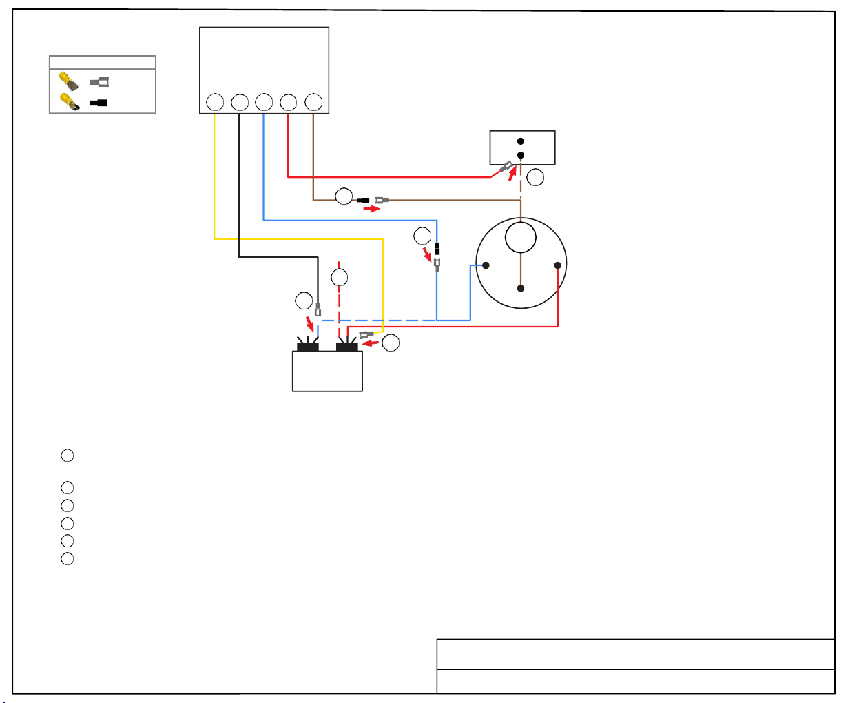
FEMALE
MALE
WIRE CONNECTOR GUIDE
3 2 1 6 5
AC
PCB
3
4
Soft
Start
5
1
4
2
BLUE
6
BROWN
OL
R
C
COMPRESSOR
S
3
C HERM
RUN
CAPACITOR
RED
TURN ALL POWER OFF BEFORE STARTING INSTALLATION.
Route all SoftStart wires into the electrical box. Then crimp Connectors onto all SoftStart wires as indicated in drawing.
Step
1
Follow Blue Compressor wire from Compressor to Run Capacitor “C” terminal. Disconnect from “C” terminal and connect it to Blue
SoftStart wire. Seal connection with electrical tape.
Step 2
Step 3
Step
4
Step 5
Step
6
Connect Black SoftStart wire to the terminal that the Blue Compressor wire was on.
Connect Yellow SoftStart wire on terminal next to Red Compressor wire on HERM terminal of Run Capacitor.
IF there is a second Red wire next to the Red Compressor wire, disconnect it, seal end with tape and drop it.
Follow Brown Compressor wire to AC PCB assembly. Disconnect it and connect to Brown SoftStart wire. Tape connection.
Connect Red SoftStart wire onto the terminal that the Brown Compressor wire was on.
Secure all wires. Seal connections with electrical tape.
Turn Power and A/C Breaker on. Turn A/C to Auto Cool setting and set the thermostat to 55ºF.
Look at SoftStart LED lights. Green light should be “on”. Green light means the Compressor is running (there may be a full 3-minute delay before
Green light comes on). IF there is no Green light after 4 minutes, call SoftStart Tech Support for assistance.
After establishing Green light operation, re-install all A/C covers.
Turn A/C on, set near to outdoor temperature and run for 30 minutes.
After 30 minutes, operate A/C normally.
YELLOW
Wiring Diagram for LG MEZ65238817 Relay
FEMALE
BLACK
FEMALE
BLUE
MALE
RED
FEMALE
BROWN
MALE