

INVISIBLE SERIES
PRE-CONSTRUCTION BRACKET MANUAL

2
INVISIBLE SERIES ACCESSORIES
Pre-Construction Bracket
TABLE OF CONTENTS
2 Box Contents
2 Introduction
2 Important Safety Information
3 Preparation
4 Pre-Construction Installation
6 Speaker Installation
7 Warranty
FRONT VIEW BACK VIEW
BOX CONTENTS
(1) IS Pre-Construction Bracket
(10) 1/4-20 Screws
(2) shims for IS Enclosure
(1) Double-sided Tape for Shims
INTRODUCTION
Thank you for selecting the Sonance Invisible Series Pre-
Construction Bracket. Sonance has over four decades of
experience in premium distributed audio. Please take
the time to carefully read through the manual, study the
illustrations, and system diagrams. This extra time can
lead to trouble-free operation and continued musical
enjoyment.
IMPORTANT: Read this section in its entirety before
attempting use of pre-construction bracket.
IMPORTANT SAFETY INSTRUCTIONS
Always follow these basic safety precautions to reduce
the risk of re, electric shock, and injury to prople or
objects.
1. Read these instructions.
2. Keep these instructions.
3. Heed all warnings.
4. Follow all instructions.
5. Clean only with a dry cloth.
6. Only use attachments/accessories specied by
Sonance.
7. Refer all servicing to qualied service personnel.
OVERVIEW | COMPATIBILITY
The Invisible Series (IS) Pre-Construction Brackets require
a compatible IS Enclosure to create a complete pre-
construction and space saving solution for Sonance
Motion Flex Invisible Series Speakers. Use the following
chart to determine which IS Pre-construction Bracket to
use. You must know which IS Speaker, which type of IS
Enclosure, and what wall board thickness will be used in
order to determine the correct bracket to use. Custom
wall board thicknesses are possible; please contact
Sonance for custom inquiries.
3
IS SPEAKER
IS SOUND ISOLATING
ENCLOSURE
WALL BOARD THICKNESS
IS PRE-CONSTRUCTION
BRACKET
IS6
IS-ENCL-S
0.5” (12.5mm) IS-S-PB.500
0.625” (15mm) IS-S-PB.625
IS-ENCL-S-NARROW
0.5” (12.5mm) IS-S-NARROW-PB.500
0.625” (15mm) IS-S-NARROW-PB.625
IS8 | IS10W
IS-ENCL-M
0.5” (12.5mm) IS-M-PB.500
0.625” (15mm) IS-M-PB.625
IS-ENCL-M-NARROW
0.5” (12.5mm) IS-M-NARROW-PB.500
0.625” (15mm) IS-M-NARROW-PB.625
IS10
IS-ENCL-L
0.5” (12.5mm) IS-L-PB.500
0.625” (15mm) IS-L-PB.625
IS-ENCL-L-NARROW
0.5” (12.5mm) IS-L-NARROW-PB.500
0.625” (15mm) IS-L-NARROW-PB.625
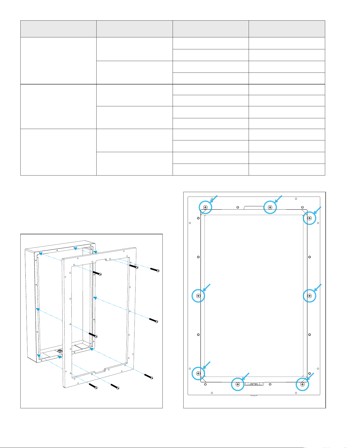
PREPARATION
Install Invisible Series Pre-Construction Bracket onto
IS Enclosure using at least eight of the included 1/4-20
screws (see Figure 1). The screw pattern (see Figure 2) is
recommended for installation efciency.
Figure 2: Screw PatternFigure 1: Screw Bracket onto Enclosure
4
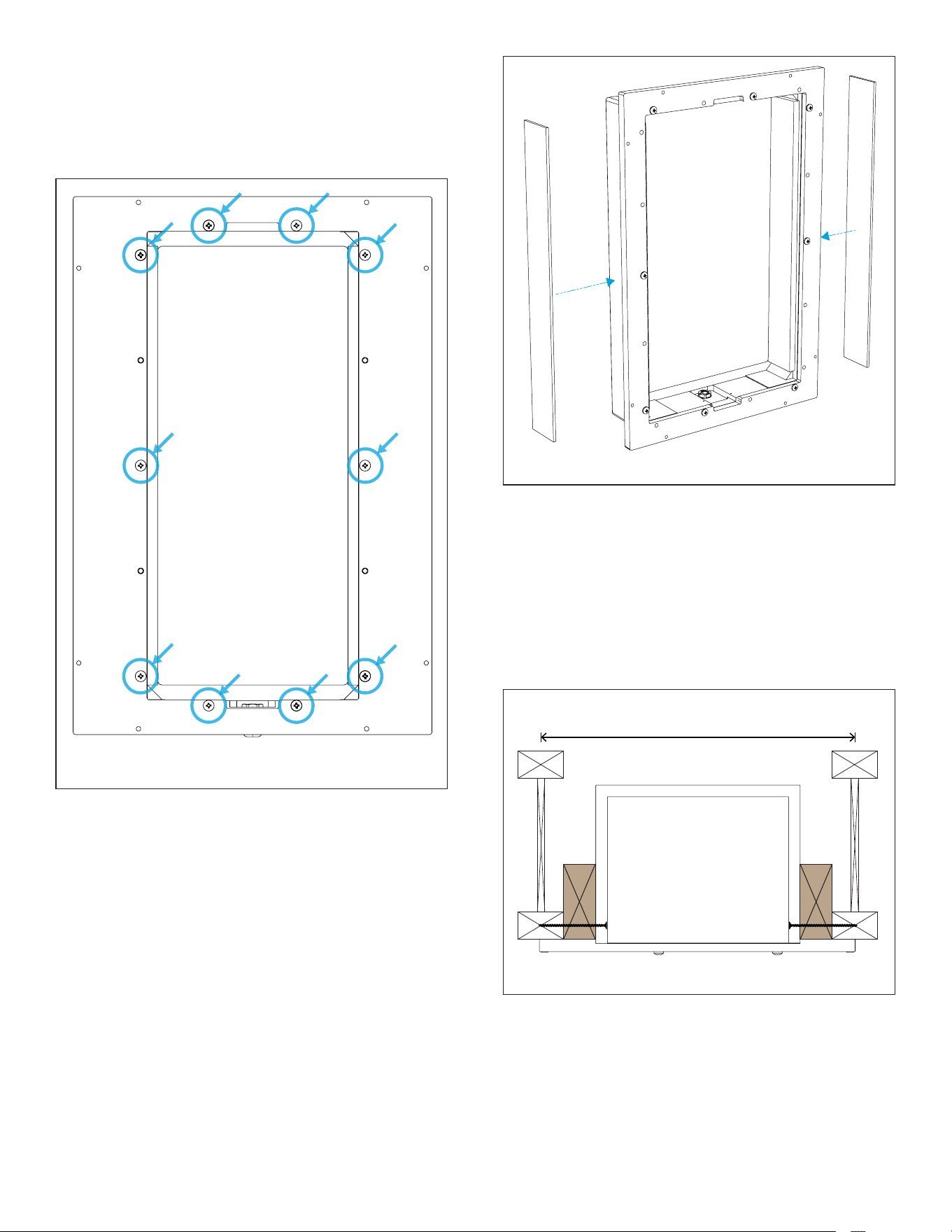
Figure 4: Attach Shims with Double-Sided Tape
For all other congurations such as 12” OC framing, TJI-
style engineered joists, and/or narrow enclosures, use
dimensional lumber, plywood, or other wood shim
material to completely ll any gap between the longer
sides of the IS Enclosure and construction framing (see
Figure 5). This shim material can be either applied to
the IS Enclosure or the framing. You may nd it easiest
to simply frame around all four sides of the enclosure to
ensure a snug t.
16” (406mm)
on-center
Figure 5: Fill Gap Around Framing
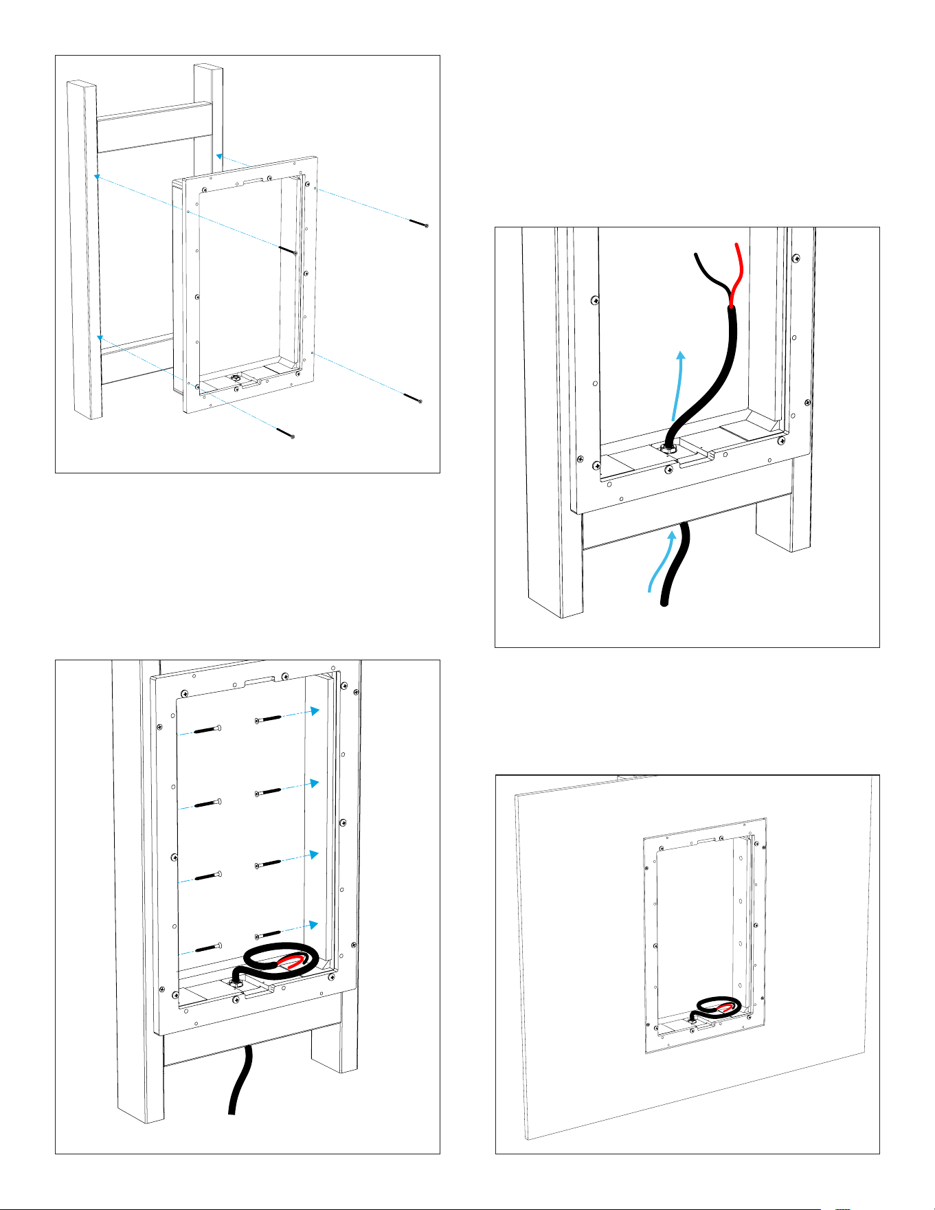
PRE-CONSTRUCTION INSTALLATION
Temporarily tack the IS Pre-Construction Bracket and
enclosure assembly to the framing using four wood
or drywall screws around the perimeter of the IS Pre-
Construction Bracket (see Figure 6).
NOTE: If using a NARROW enclosure, you must pre-drill
pilot holes into the enclosure before the bracket can be
installed. Use the bracket as a hole guide and drill ten
holes 7/32” (5.5mm) diameter at a depth of 2” (50mm).
Use the screw pattern for where to drill the holes (see
Figure 3).
Figure 3: Narrow version ONLY
Drill Holes on Screw Pattern
SHIMS AND FRAMING SUPPORT
Shims must be used to ll any gaps between the longer
sides of the Invisible Series Enclosure and inside surfaces
of construction framing. This will prevent damage and air
leaks in the enclosure when it is anchored to the framing.
For the most common scenario of 16” OC framing and
standard width enclosures (non-narrow enclosures), use
the supplied double-sided adhesive tape to attach the
shims as shown (see Figure 4).
5
Pre-drill eight pilot holes (four on each side, evenly
spaced) through the inside of the IS Enclosure walls,
through any shims you have installed, and into the
framing (see Figure 7). Avoid drilling the pilot holes near
any holes on the face of IS Pre-Construction Bracket.
Securely anchor the IS Enclosure to the framing using
standard at head #8 or #10 construction screws (metric
equivalent 4–5mm) long enough to drive at least 1”
(25mm) into the framing.
Figure 6: Tack Bracket and Enclosure into Place
Figure 7: Pre-Drill Pilot Holes
IMPORTANT NOTE FOR NARROW ENCLOSURES: Use
the pre-existing holes in the sides of the enclosure
to secure to the framing. The screw heads must be
countersunk into the IS enclosure walls so that they
do not protrude. If you fail to do this, the IS Speaker
will not t. After the screws are installed, you must use
gaffer tape or similar to cover all screws and all holes
in the walls of the IS Narrow Enclosure to prevent air
leaks. Do not skip this step.
Figure 8: Run Speaker Wire Through Enclosure
Allow other trades to complete their work including
wall board installation (see Figure 9). The bracket and
enclosure will act as a space saver. The outside edge of
the bracket may also be used as a wall board cutout
guide by using a zip tool to cut the wall board around
the bracket.
Figure 9: Wall Board Installation
6
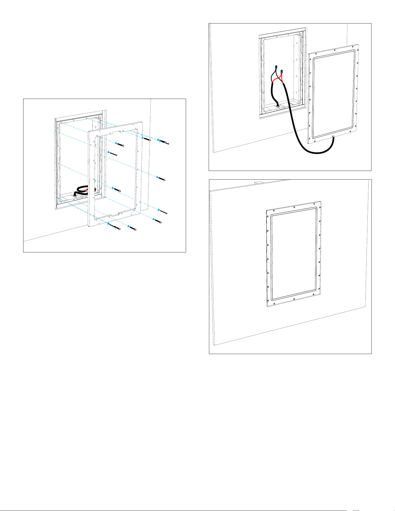
Figure 10: Remove Pre-Construction Bracket
IMPORTANT: Use the shims supplied with the Invisible
Series Speakers if necessary to ensure the face of the
IS Speaker is perfectly ush with the surface of the
surrounding wall board. THIS STEP IS CRITICAL!
With the bracket removed, connect the wire leads from
the IS Speaker to the pre-wired speaker wires inside the
enclosure using wire nuts or level-lock style connectors
(see Figure 11). Tuck the wiring out of the way to the side
of the enclosure. Insert the IS Speaker into the enclosure
and anchor the speaker to the framing, following the
normal instructions for IS Speakers (see Figure 12).
Figure 12: Insert and Anchor the IS Speaker
Figure 11: Connect the Wire Leads
FINISHING
Finishing the Invisible Series Speakers can be performed
as usual from this stage forward. Refer to the nishing
steps in the IS Speaker manual and carefully follow all
steps.
SPEAKER INSTALLATION
After the wall board is roughed in and before the
nishing stage, remove the IS Pre-Construction Bracket
by taking out all the outside screws used to tack the
bracket to the framing and the 1/4-20 screws used to
attach the bracket to the enclosure (see Figure 10). Do
not remove the inner construction screws used to anchor
the enclosure to the framing. Save the 1/4-20 screws so
the IS Pre-Construction Bracket can be re-used.

7
©2023 Sonance. All rights reserved. Sonance is a registered trademarks of Dana Innovations. Due to continuous product improvement, all features and
specications are subject to change without notice. For the latest Sonance product specication information visit our website: www.sonance.com
SONANCE • 991 Calle Amanecer • San Clemente, CA 92673 USA • PHONE: (949) 492-7777 • FAX: (949) 361-5151 • Technical Support: (949) 492-7777
11.10.2023
LIMITED FIVE (5) YEAR WARRANTY
Sonance warrants to the rst end-user purchaser that this Sonance-brand product (Sonance Invisible Series Pre-Construction Bracket)
when purchased from an authorized Sonance Dealer/Distributor, will be free from defective workmanship and materials for the period
stated below. Sonance will at its option and expense during the warranty period, either repair the defect or replace the Product with a new
or remanufactured Product or a reasonable equivalent.
EXCLUSIONS: TO THE EXTENT PERMITTED BY LAW, THE WARRANTY SET FORTH ABOVE IS IN LIEU OF, AND EXCLUSIVE OF, ALL OTHER
WARRANTIES, EXPRESS OR IMPLIED, AND IS THE SOLE AND EXCLUSIVE WARRANTY PROVIDED BY SONANCE. ALL OTHER EXPRESS
AND IMPLIED WARRANTIES, INCLUDING THE IMPLIED WARRANTIES OF MERCHANTABILITY, IMPLIED WARRANTY OF FITNESS FOR USE,
AND IMPLIED WARRANTY OF FITNESS FOR A PARTICULAR PURPOSE ARE SPECIFICALLY EXCLUDED.
No one is authorized to make or modify any warranties on behalf of Sonance. The warranty stated above is the sole and exclusive remedy
and Sonance’s performance shall constitute full and nal satisfaction of all obligations, liabilities and claims with respect to the Product.
IN ANY EVENT, SONANCE SHALL NOT BE LIABLE FOR CONSEQUENTIAL, INCIDENTAL, ECONOMIC, PROPERTY, BODILY INJURY, OR
PERSONAL INJURY DAMAGES ARISING FROM THE PRODUCT, ANY BREACH OF THIS WARRANTY OR OTHERWISE.
This warranty statement gives you specic legal rights, and you may have other rights which vary from state to state. Some states do not
allow the exclusion of implied warranties or limitations of remedies, so the above exclusions and limitations may not apply. If your state
does not allow disclaimer of implied warranties, the duration of such implied warranties is limited to period of Sonance’s express warranty.
Your Product Model and Description: Sonance Invisible Series Pre-Construction Bracket. Warranty Period for this Product: Five (5) years
from the date on the original sales receipt or invoice or other satisfactory proof of purchase.
Additional Limitations and Exclusions from Warranty Coverage: The warranty described above is non-transferable, applies only to the
initial installation of the Product, does not include installation of any repaired or replaced Product, does not include damage to allied or
associated equipment which may result for any reason from use with this Product, and does not include labor or parts caused by accident,
disaster, negligence, improper installation, misuse (e.g., overdriving the amplier or speaker, excessive heat, cold or humidity), or from
service or repair which has not been authorized by Sonance.
Obtaining Authorized Service: To qualify for the warranty, you must contact your authorized Sonance Dealer/Installer or call Sonance
Customer Service at (949) 492-7777 within the warranty period, must obtain a return merchandise number (RMA), and must deliver the
Product to Sonance shipping prepaid during the warranty period, together with the original sales receipt, or invoice or other satisfactory
proof of purchase.
Warranty Process: Please follow the troubleshooting instructions in this manual or work with your Sonance dealer to determine the exact
nature of the fault. Sonance provides a 5-Year Limited Warranty to the original owner with proof of purchase from an authorized Sonance
dealer. The warranty does not cover shipping charges back to Sonance or the use of the product in an environment or application not
approved by Sonance.
In order to initiate a warranty claim:
1. Contact Sonance Technical Support with a description of the fault, the amplier’s serial number and the date of purchase from an
authorized Sonance dealer at: technic[email protected]om
2. Sonance Technical Support will follow-up and may request additional troubleshooting.
3. Once a determination has been made on the fault, Sonance Customer Service will follow-up by email. Please have a scanned copy of
your Sonance Invisible Series Pre-Construction Bracket sales invoice ready to send upon request to document the speaker’s warranty
status.
4. Sonance Customer Service will provide an RMA number to be included on the shipping label of the packaging. Please send the
speaker back in its original factory carton, which has been specically designed to protect the speaker during transit.
Contact us at: https://www.sonance.com/company/contact
