
LIFESTYLE REFRIGERATION
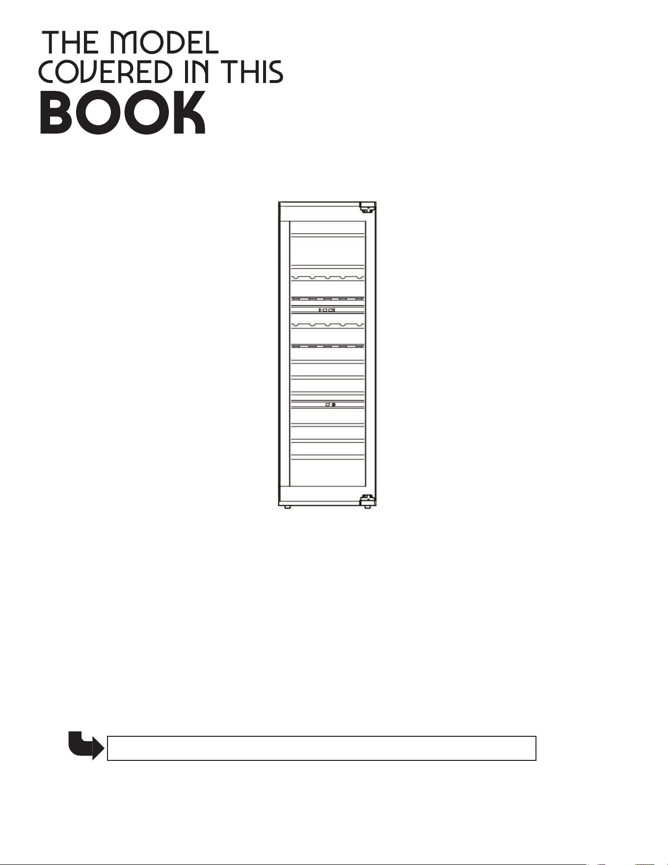
MODEL: XOU2470WTZGO

3
APPLIANCE
4
5 - 8
9 - 14
15 - 20
21 - 22
23 - 24
Reversing the Door
Anti-Tip Bracket
5
2
record your serial number
here in case you need it later
XOU2470WTZGO
6
7
8
built to be built-in
9
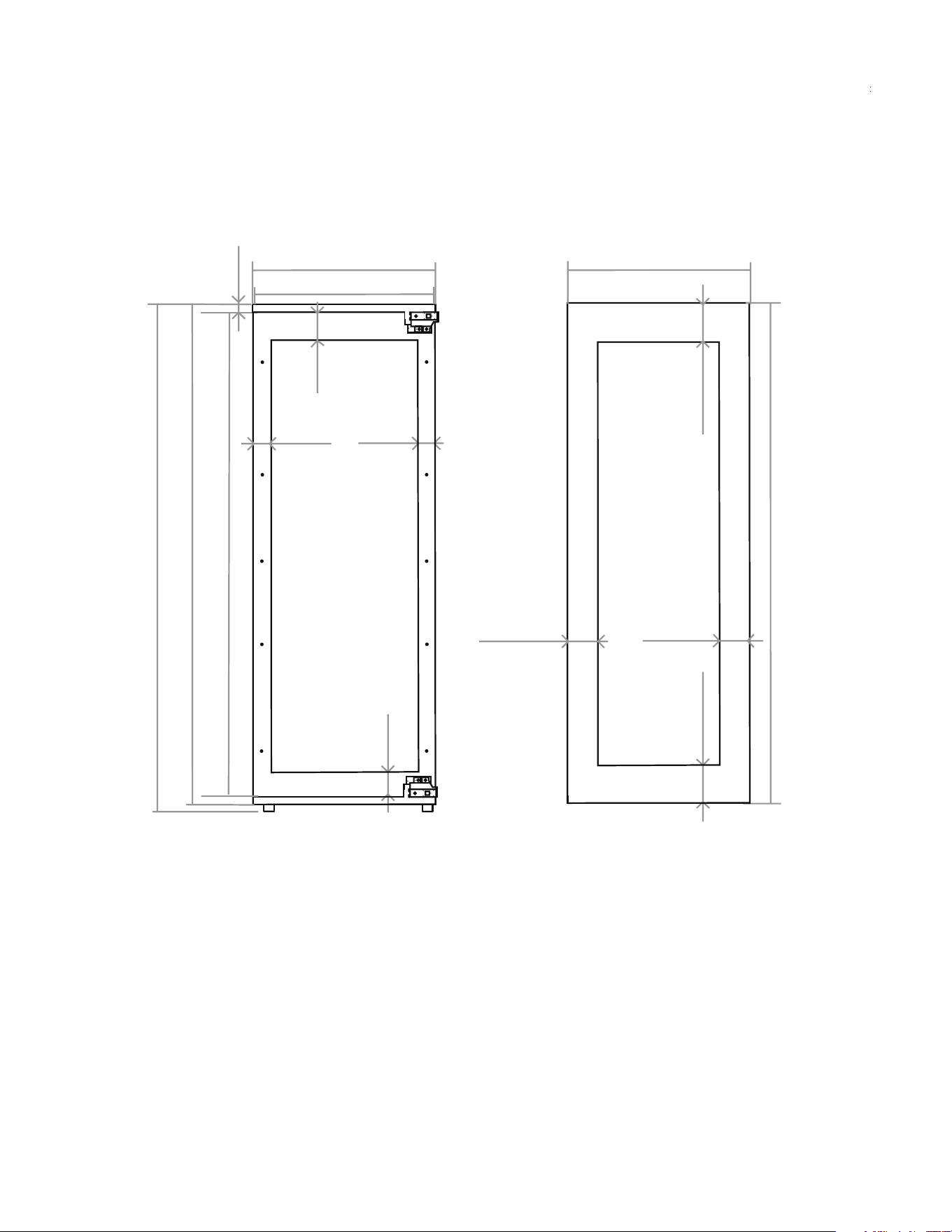
1 1/2”
69 3/8”
22”
22 13/16”
OVERALL UNIT DIMENSIONS
68 11/16”
21 7/8”
66 1/8”
19 3/4”
68”
2”
21 1/2”
20”
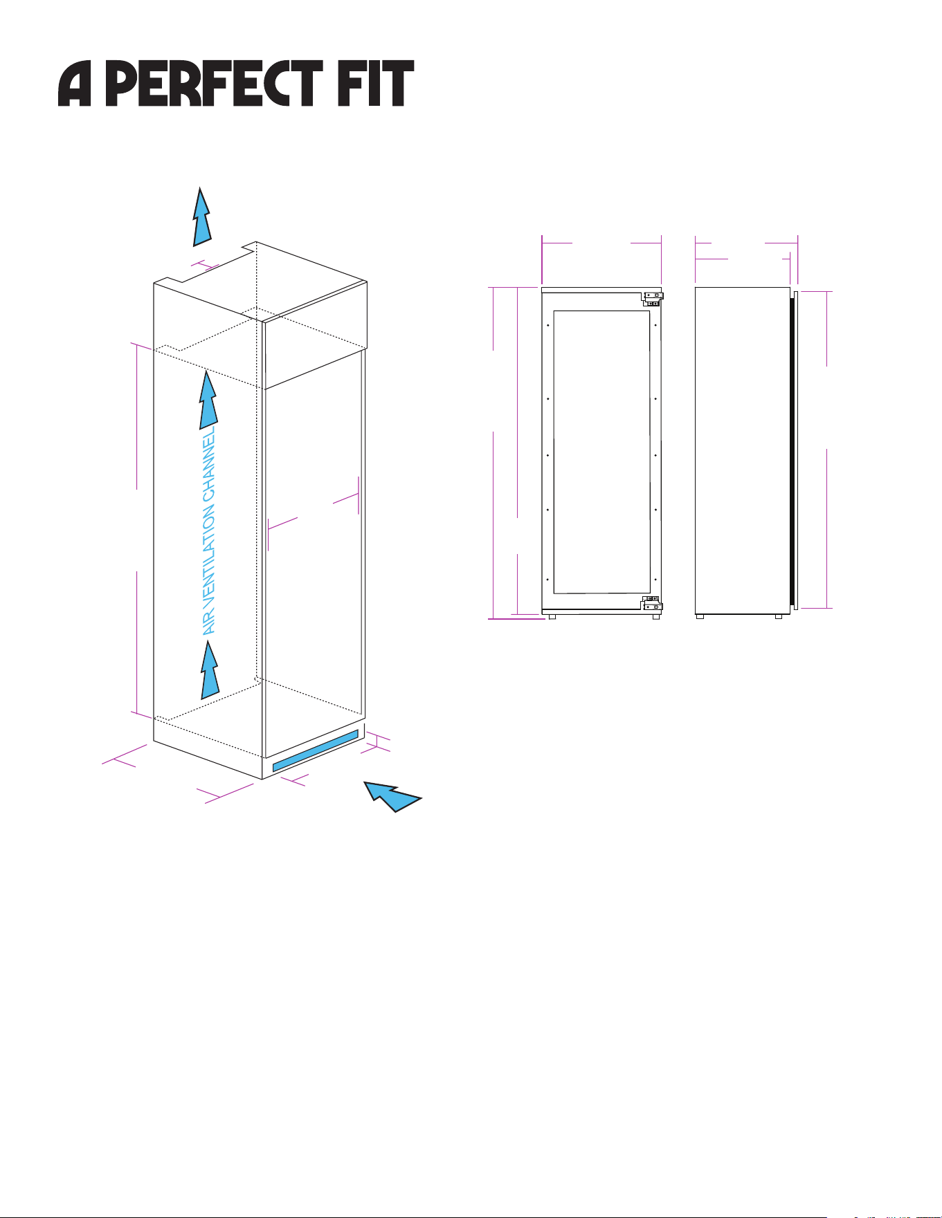
PROPER VENTILATION
Your XO Wine Cabinet must be vented to operate
properly. Air enters below the cabinet in the front,
passes up behind the unit and exits at the top.
The rear of the cabinet should remain completely
open to maximize cooling air flow.
It is imperative the 1 1/2” deep channel opennings
remain free of obstruction.
If a decorative grill is used to cover the toe kick
vent, the open area of the grill must be larger than
31 sq in.
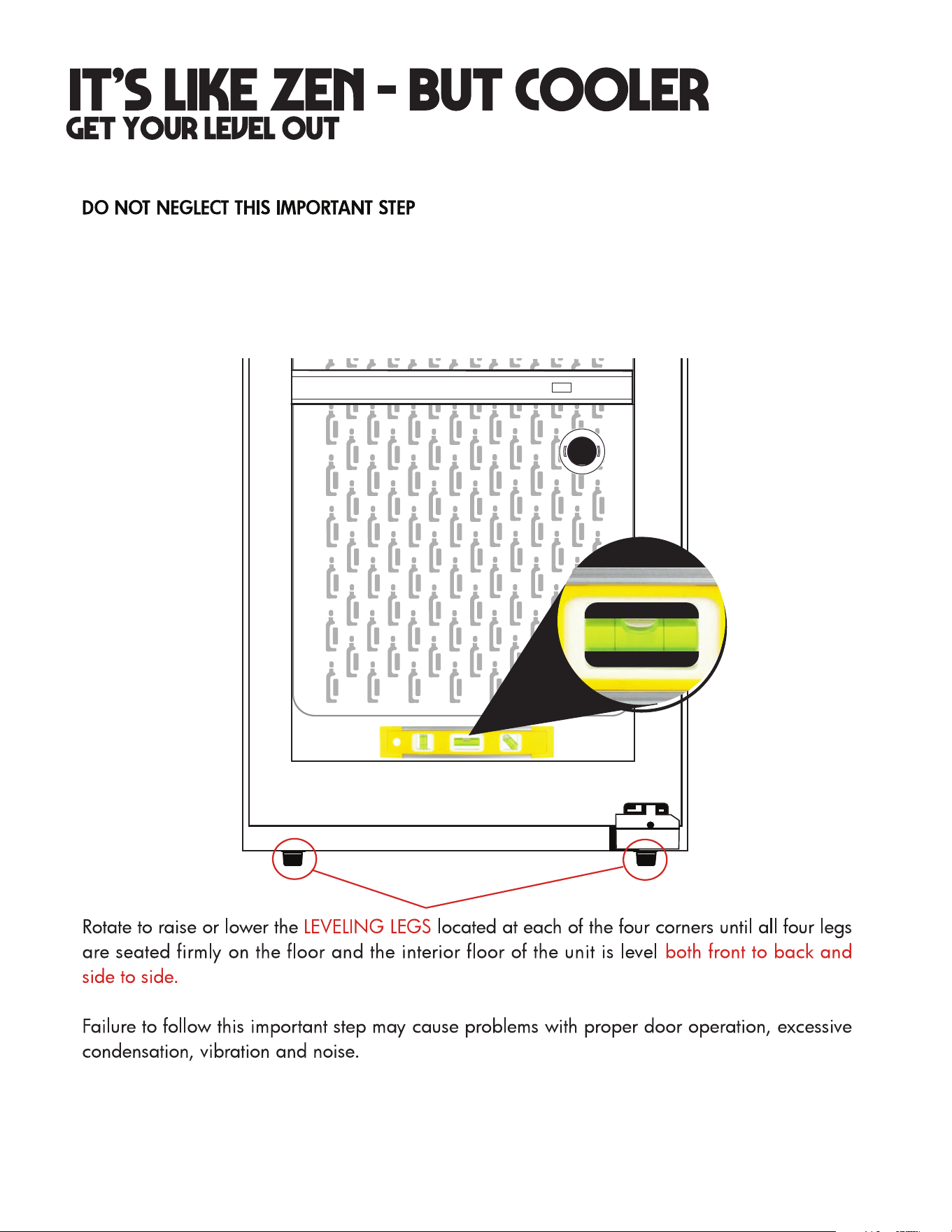
PLUMB, LEVEL AND SQUARE
The cabinet base for your XO Wine Refrigerator must be level and the cabinet sides and front must be
properly squared for the unit to fit properly.
Failure to square and level the cabinet and refrigerator cause cause problems with the unit’s operation,
prevent the door from sealing properly, result in a misalignment of the cabinetry and other issues.
After the refrigerator is installed the leveling feet may be used to make minor adjustments.
WARNING: Do not attempt to reverse the door alone. This operation requires at least two
people to be performed safely. The door is large, heavy and fragile.
READ THESE INSTRUCTIONS COMPLETELY BEFORE BEGINNING - IF YOU ARE UNSURE
ABOUT PROCEEDING, STOP AND CALL FOR SERVICE.
.
10
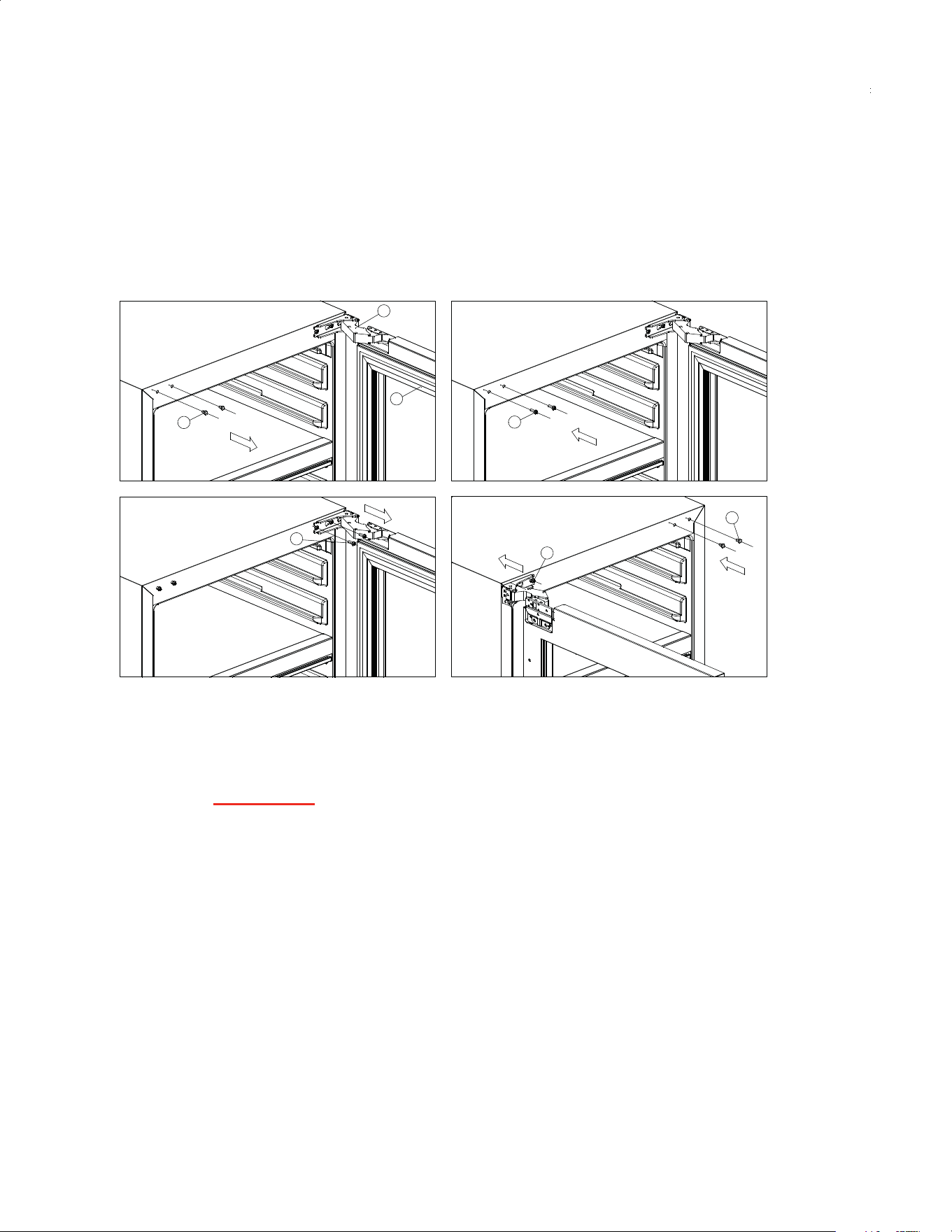
reversing the door
Your XO arrives with a right hand hinged door - but it is easily to reverse if you choose.
To reverse the hinge on your unit, follow the directions below:
1.
Open the door and remove the screw hole covers (1) on the left hand side as shown
in Fig A.
.4egniH .3rooD .2 srevoc eloh wercS.1 Screws
Fig.A
Fig.C
Fig.B
1
2
3
4
4
Fig.D
4
1
2. Start screws into these positions as per Fig B, but do not tighten the screws.
3. Remove all screws from both the upper and lower hinge, and then remove the door.
4. Rotate the door 180 degrees, (top to bottom) and place the hinges onto the screws
(4) in Fig B. Slide the slots of the hinge until fully seated against the screws, then
tighten the screws to secure the hinges (Fig D).
5. Place the screw hole covers in the right hand side screw holes as shown in Fig D.
BEFORE BEGINNING, REMOVE THE RACKS & LAY THE UNIT FLAT ON ITS BACK.
TEAM LIFT - THIS REQUIRES TWO OR MORE PEOPLE.
11
12
WARNING: Do not attempt to reverse the door alone. This operation requires at least two
people to be performed safely. The unit is large, heavy and fragile.
.
let’s face it
21 7/8”
68”
68 11/16 “
3 3/8”
66 1/8”
15/16”
* The height of the furniture door will need to be adjusted to ensure it lines up with the other kitchen
cabinet doors, therefore these dimensions will vary.
21 7/16”
2 3/16” 2 3/16”
min 5 11/16”
70” *
23 9/32”
min 3 1/8”
3 3/8”
min 3 1/8”
min 5 11/16”
Once the door (hinge) orientation is correct and the refrigerator is leveled and
secured in the cabinet - it is time to mount the overlay panel.
Prepare your overlay panel using the guidelines shown here. Dimensions may be
adjusted to accommodate your cabinetry but the panel cannot exceed 40lbs in
weight and cannot be more than 13/16” thick.
To minimize warping the panel must be finished on both sides.
*The height dimension will vary to match up with other cabinet doors.
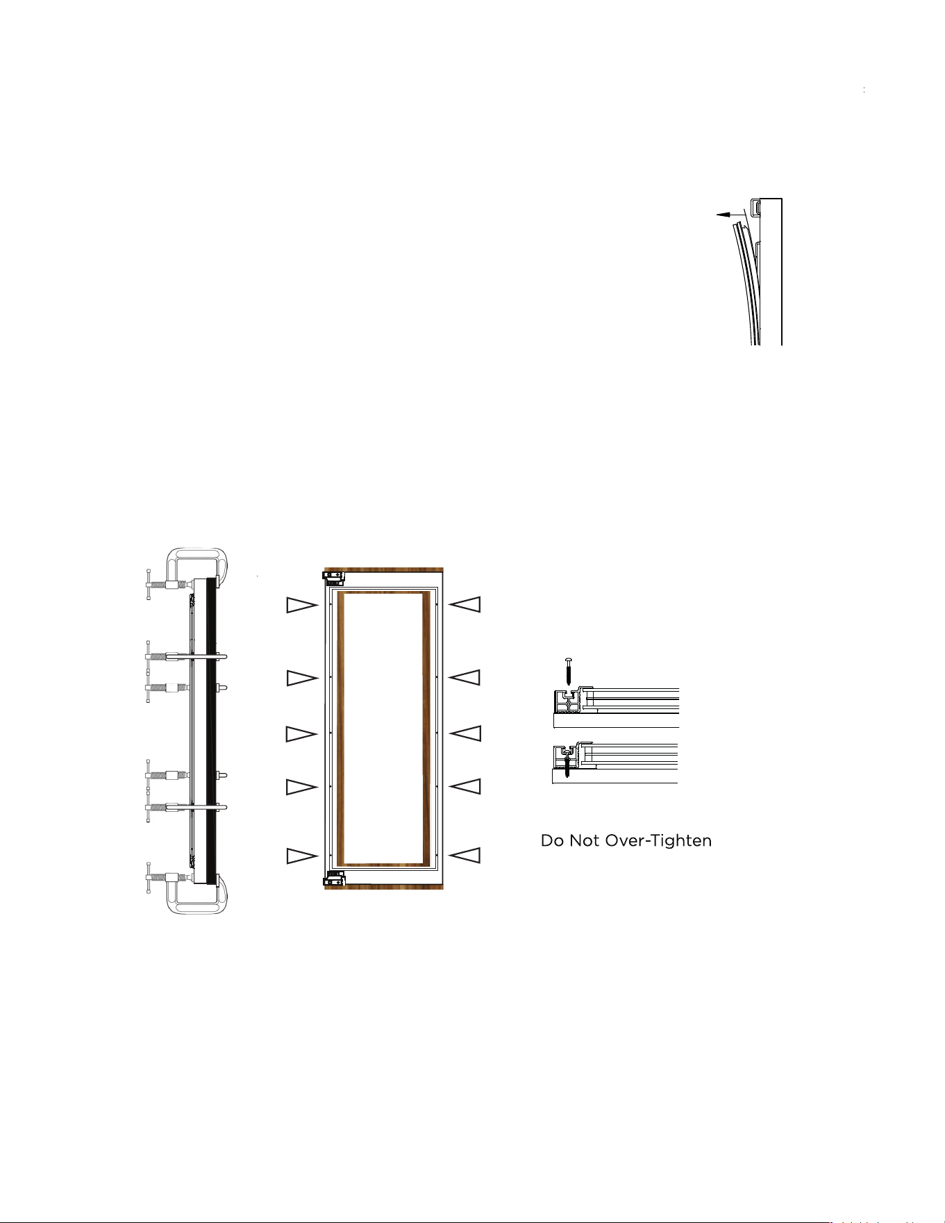
1. Fully open the door and pull the gasket
out of the gasket channel.
starting at one corner
2. After removing the gasket lay it out on a flat surface to retain its shape.
3. Using clamps to hold it securely in place, position the overlay panel against the door.
4. Using the frame as a guide, drill ten (10) pilot holes i1/8” (3mm) in dia. into the finish panel
taking care not to drill through the panel.
5. Using ST4-30 self-tapping screws, fasten the panel to the door frame.
6. Beginning at one corner, re-install the rubber door gasket into the gasket channel.
BEFORE BEGINNING: Attach any handle hardware before mounting the panel to the door frame.
Mounting screw holes are located
in the gasket channel behind the gasket.
S
IMPORTANT NOTE: The back of the panel must be finished to prevent warping and cracking.
13
let’s face it
14
installing anti-tipping measures
2
1
1
2
3
1
1
Fig.A Fig.B
Fig.C
FIG. A
FIG. B
FIG. C
FIG. D
no tipping
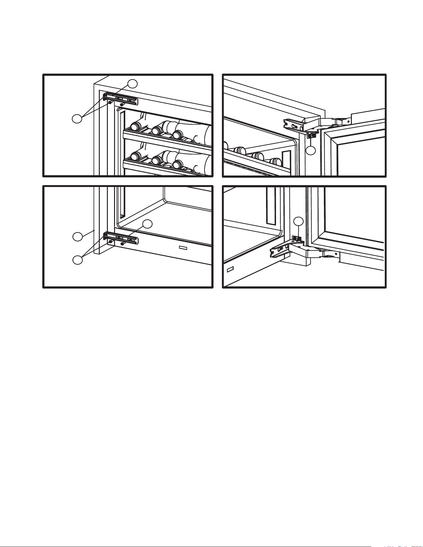
To prevent the wine refrigerator from accidental tipping, it fastens to the cabinetry in
four (4) locations.
The articulating hinges each have screw down tabs to enable them to be screwed to
the side walls of the cabinetry. See Figures B & D.
Included with the unit are also two (2) Anti-Tip brackets which install in the upper &
lower corners on the handle side. See Figures A & C. Each bracket attaches to the
face of the refrigerator with two (2) screws. Don not tighten the screws completely
allowing each bracket to slide sideways. Push each bracket outward and fasten to
the cabinet wall. Then tighten the screws holding each bracket to the front of the
refrigerator cabinet.
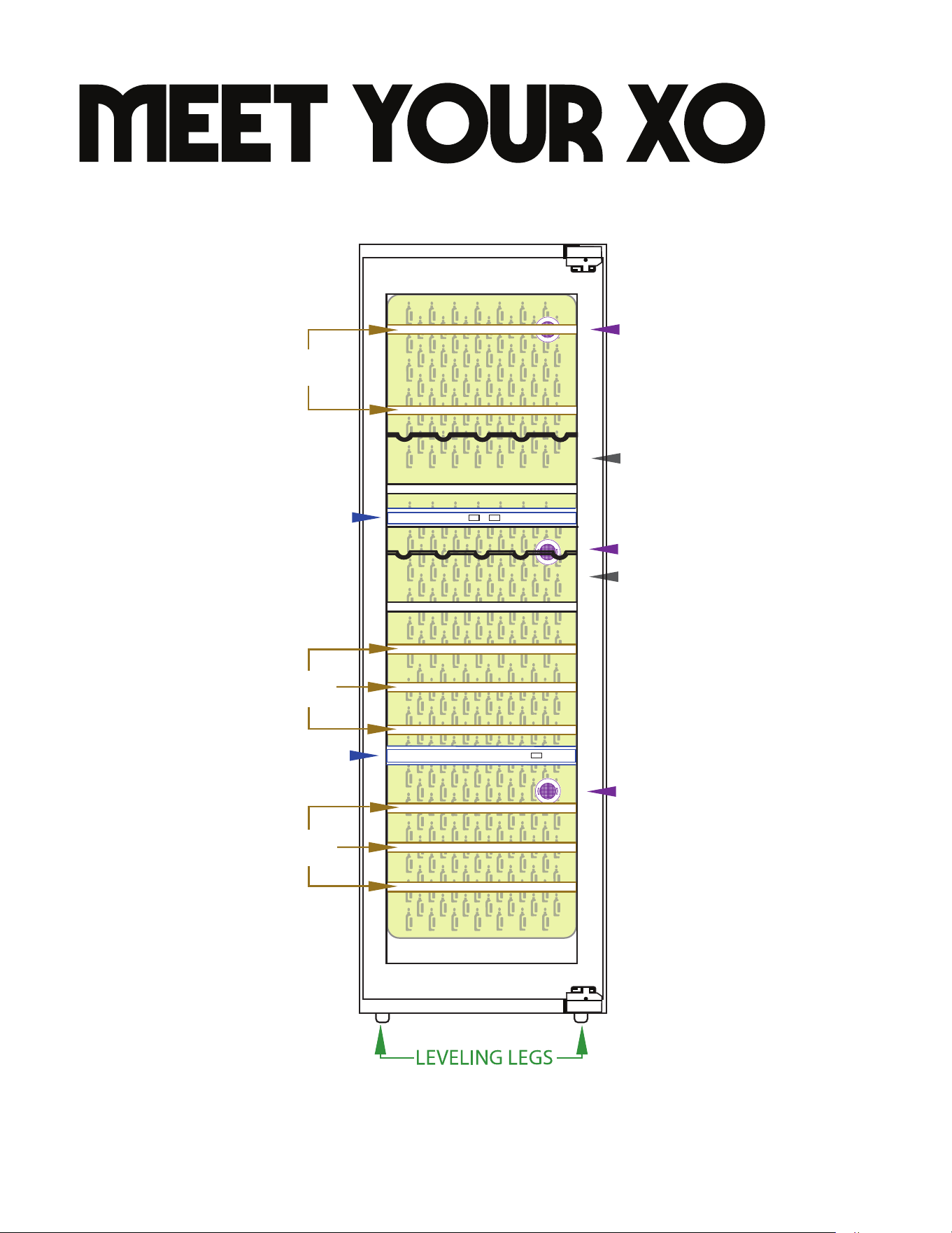
BOTTLE DISPLAY RACK
BOTTLE DISPLAY RACK
LOWER ZONE
CONTROL PANEL
15
UPPER & MIDDLE ZONE
CONTROL PANEL
BOTTLE STORAGE RACK
BOTTLE STORAGE RACK
BOTTLE STORAGE RACK
CARBON AIR FILTER
CARBON AIR FILTER
CARBON AIR FILTER
16
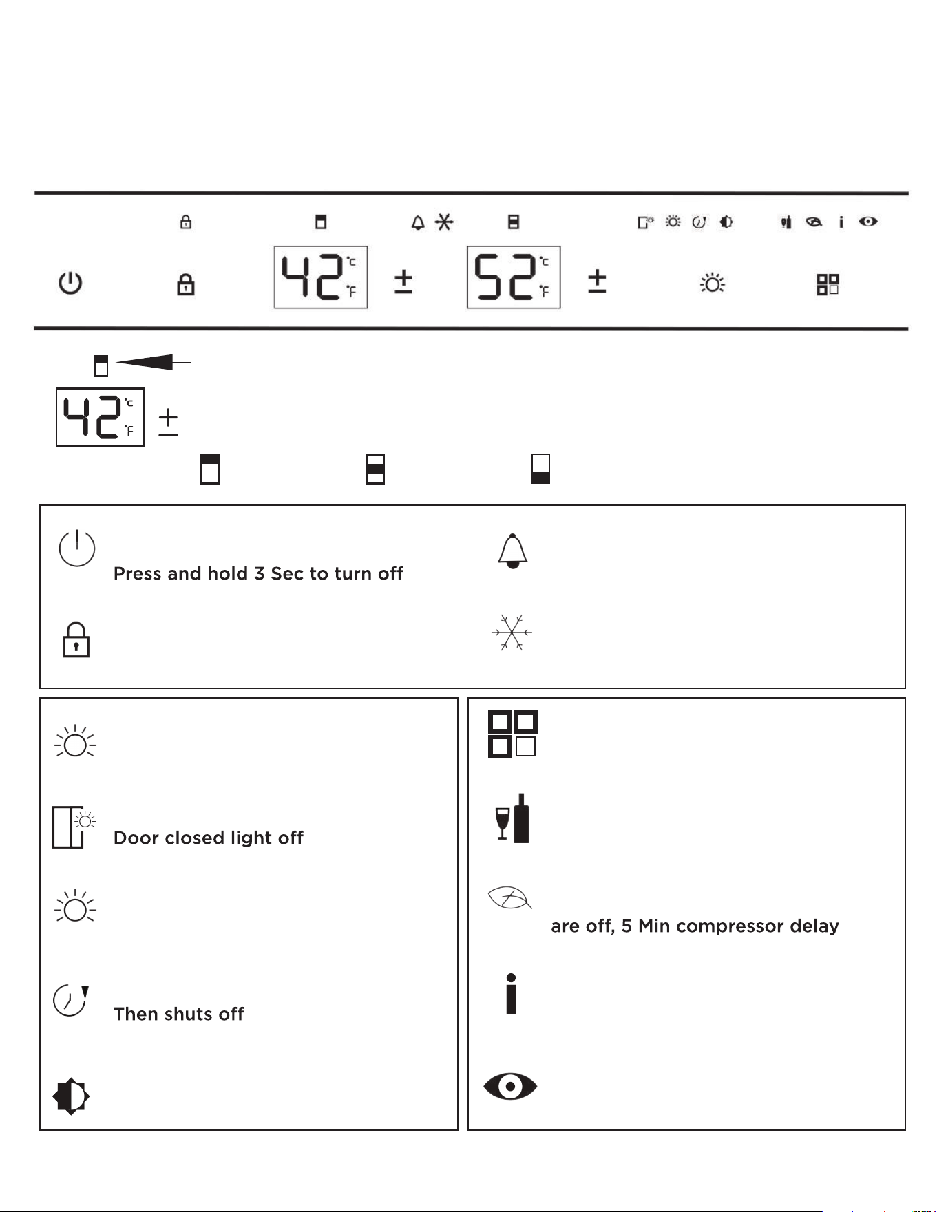
triple zone control
requires two conrol panels
UPPER PANEL: Controls all functions and temperature in the upper and middle zones
ON/OFF
Press & hold 1 Sec to turn on.
PANEL LOCK
Press & hold 3 Sec to activate
or deactivate
LIGHTING FUNCTIONS BUTTON
Toggles between lighting options
LI
Door open light on
L2
Light on continuously
Dims after 3 Min
L3
Light remains on for 10 Min
BRIGHTNESS FUNCTION
Hold for 3 Sec - Begins flashing
Use keys to adjust lighting
+
-
ALARM INDICATOR
Illuminates when the unit is in
an alarm state
COOLING INDICATOR
Illuminates when the unit is currently
cooling
OPERATING MODE BUTTON
Toggles between operating modes
STANDARD MODE
All standard cooling, alarm &
lighting functions active
ECO MODE
LED display, control & interior lights
INTELLIGENT MODE
Fans modulate speed to reduce
noise & save energy
DEMO MODE
Compressor, PTC heater & HI/LO
alarm disabled, fan reduced to 9V
Each zone has its own temperature control and is designated by the icon
above the display.
Press the to raise the zone temperature 1 at a time.
When the upper limit is reached, it reverts to the lowest setting.
+
-
o
UPPER MIDDLE LOWER
41 - 64 41 - 50 50 - 64
o o
o o
o o
17
triple zone control
requires two conrol panels
LOWER PANEL: Controls temperature in the lower zone
Each zone has its own temperature control and is designated by the icon
above the display.
Press the to raise the zone temperature 1 at a time.
When the upper limit is reached, it reverts to the lowest setting.
+
-
o
UPPER MIDDLE LOWER
41 - 64 41 - 50 50 - 64
o o
o o
o o
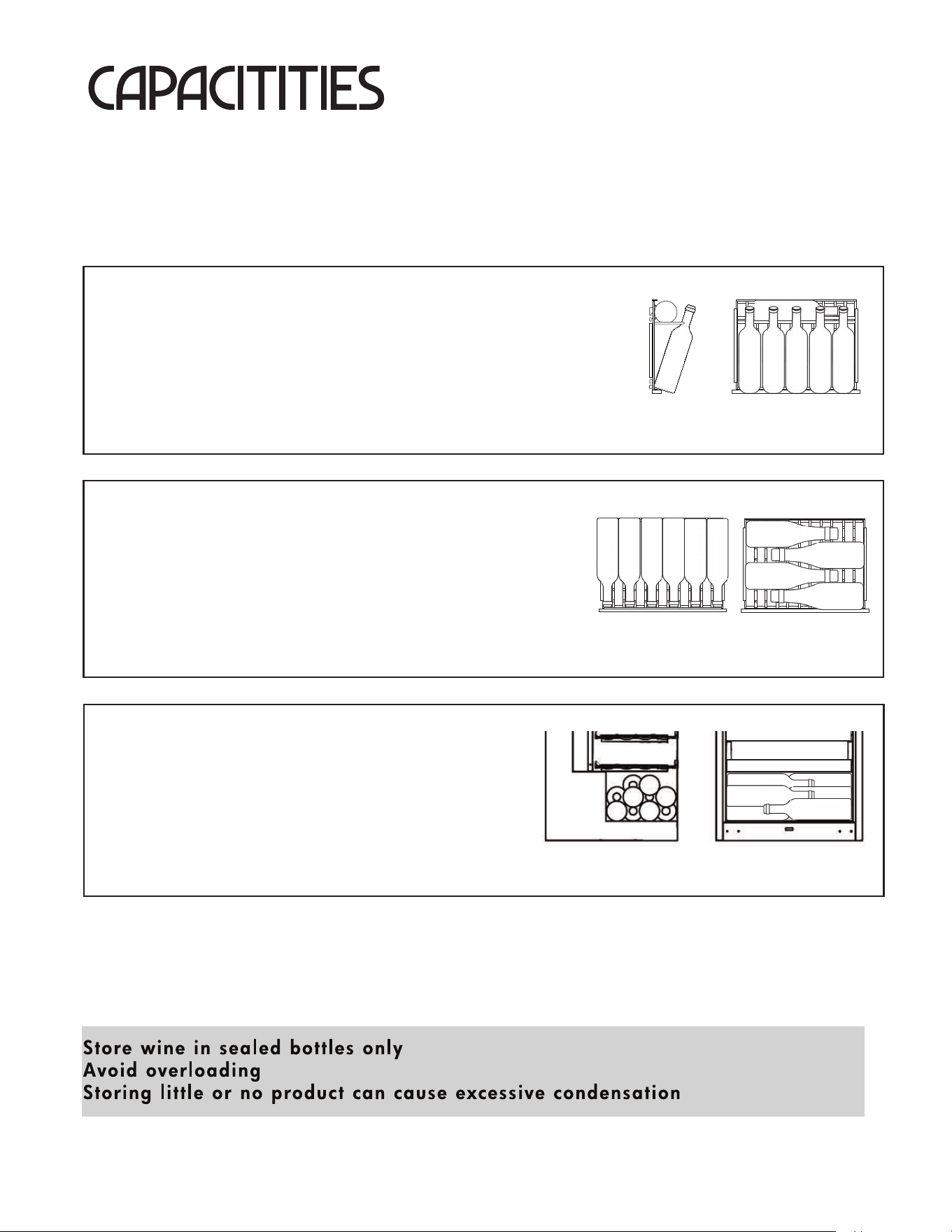
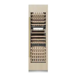
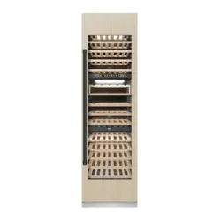
how much can my unit hold
Wine bottles come in a host of different sizes and shapes.
The following is provided as a general guideline, wine bottles are assumed to 750ml / Bordeaux style
unless otherwise noted.
WINE DISPLAY RACKS
These racks prominently display (5) 750ml Bordeaux style bottles
with the ability to hold one more behind.
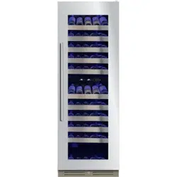
Your XOU2470WTZGO has (2) display racks - one each in the
upper and middle zone.
WINE STORAGE RACKS
Wine storage racks can hold up to (6) 750ml Bordeaux
style bottle, alignedfront to back, or larger champagne
bottles aligned side to side.
Your XOU2470WTZGO has a total of (8) wine storage racks.
BOTTOM STORAGE
18
Your XOU2470WTZGO has the ability to store additional
bottles in the base, below the bottom wine rack.
Shown right, (10) 750ml Bordeaux bottles stacked
side to side.
SIDE TOP
TOP TOP
SIDE FRONT
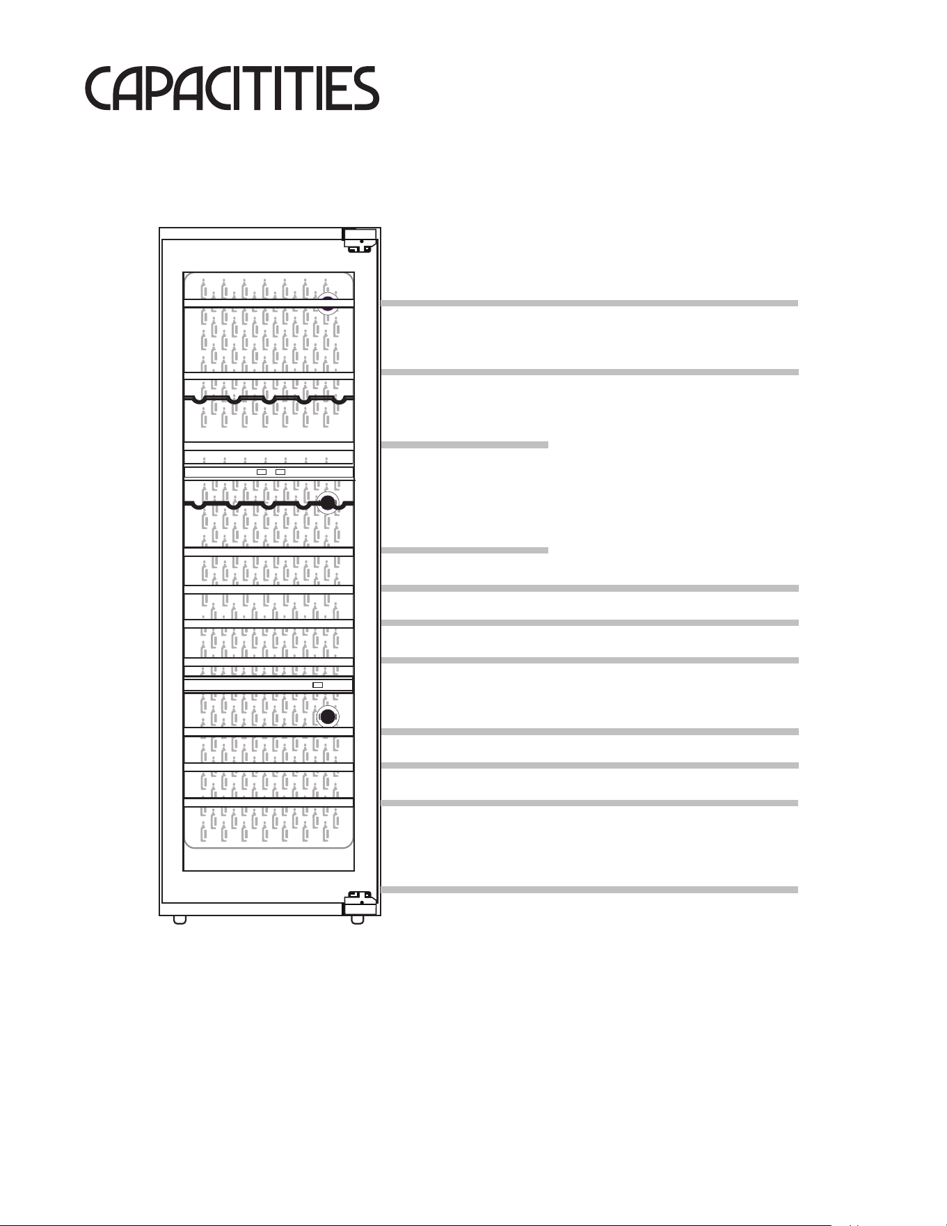
3 ZONE WINE
Assumptions are taken regarding bottle / can size and shape.
Values are max loading estimates.
how much can my unit hold
19
BORDEAUX CHAMPAGNE
6 or 4
6 or 4
6
6
6 or 4
6 or 4
6 or 4
6 or 4
6 or 4
6 or 4
10
HOLDS UP TO (70) 750ml BORDEAUX STYLE BOTTLES
1
2
20
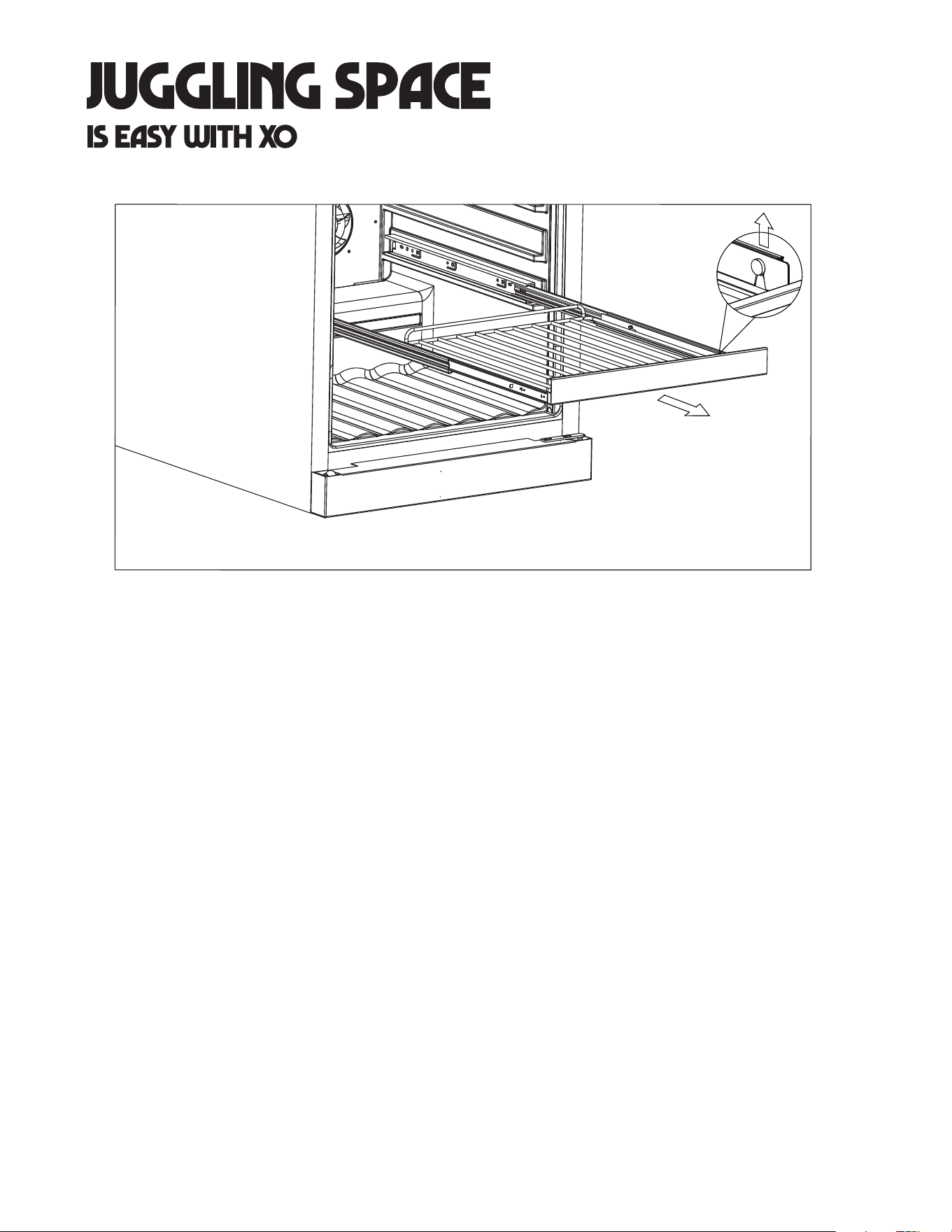
Fully extend the rack you wish to remove,
Lift the front of the rack up to remove from the front clips,
While holding one of the telescoping glides, push the rack in and pull up at the back
to release it from the rear clip.
Repeat with the other side to complete disconnecting the rack.
1.
2.
3.
ALL RACKS MUST BE PUSHED ALL THE WAY IN BEFORE CLOSING THE DOOR
DOOR MUST BE FULLY OPENED BEFORE PULLING RACKS OUT
21
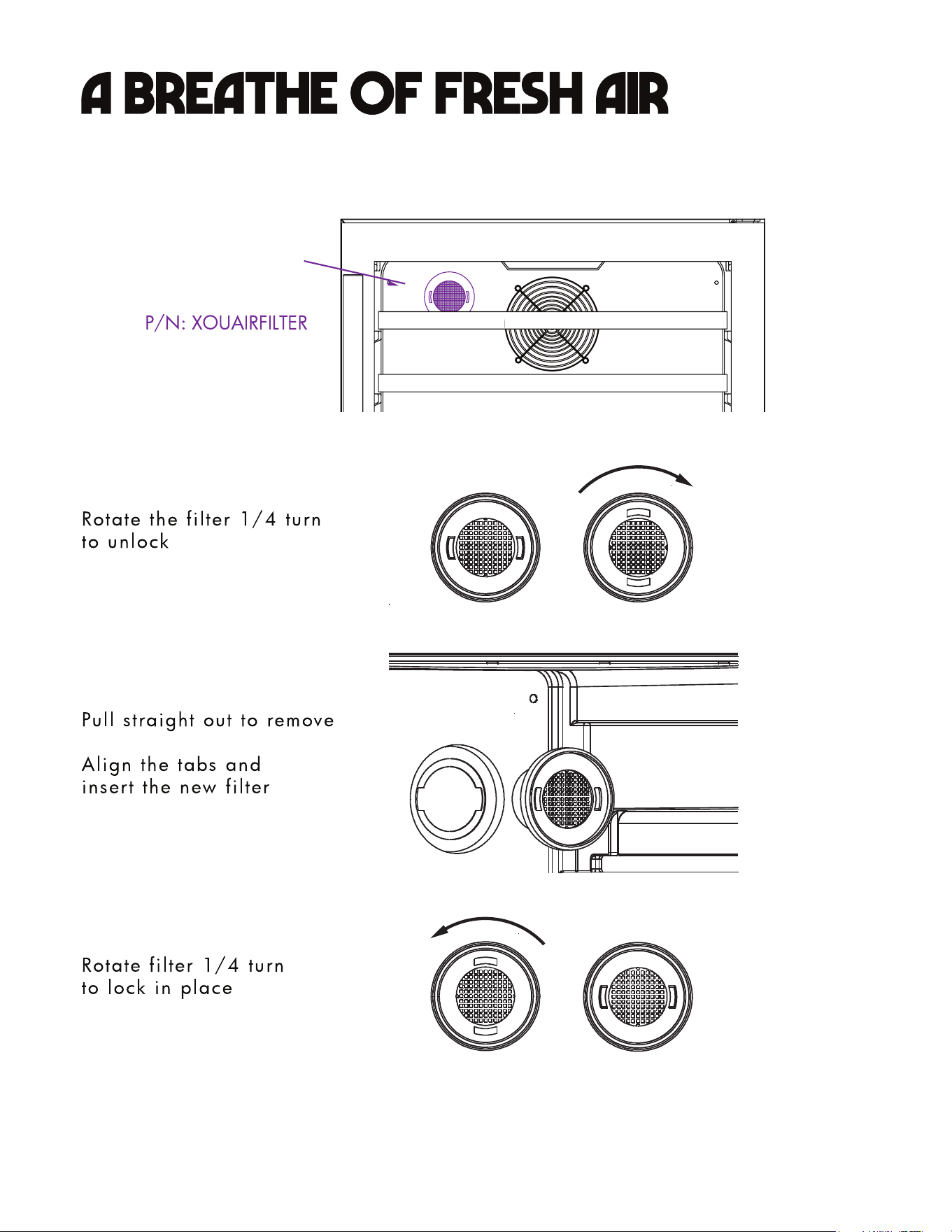
The location of the
Air Filter will vary
according to model
NOTE: Not all models are equipped with XOUAIRFILTER
22
23
2023.04.18
XOU2470WTZGOMAN23
24